1
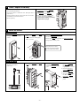
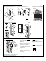
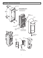
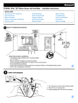
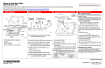
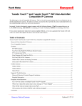
5800PIR-OD Wireless Outdoor Motion Sensor – Installation Instructions GENERAL INFORMATION The Honeywell 5800PIR-OD Wireless Outdoor Motion Sensor (referred to as the 5800PIR-OD) combines the convenience of wireless technology with a full featured outdoor PIR motion sensor. The major features are highlighted below: Immunity to bright light disturbances from headlights, sunlight, and other bright light sources. Selectable detector range and angle. Discriminates both large and small animals to reduce false alarms. Tamper detection. Battery saving circuit allows for a 5 or 120 second period of inactivity before being reactivated. SPECIFICATIONS Range Adjustable up to 12m (40ft) Pattern 90° pattern consisting of 13 zones. This pattern can be adjusted in 15° increments from center up to 45°. Sensitivity 2.0° C at 0.6m/s (3.6° F at 2.0ft/s) Detection Speed 0.3 - 1.5m/s (1 - 5ft/s) Operating Voltage 6 VDC (uses 4 lithium 1.5VDC AA cells) Battery Saving Timer Adjustable 120sec or 5sec Alarm Period ~ 2.5 seconds LED Indicator Enabled during a walk test. Disabled for normal operation. Weatherproof IP54 compliance Detection Method Passive Infrared Operating Temperature – 20 to + 50 ° C (– 4 to +122° F) Initial Warm Up ~ 2 minutes Humidity 95% Max Dimensions Height 199mm (7.8 in.) Width 82mm (3.2 in.) Depth 120mm (4.7 in.) Accessories (included) Pole mounting kit, screw kit, detection masking strips. Mounting Height 0.8 - 1.2m (2.7 - 4ft) To the center of lens. INSTALLATION (refer to the Component Identification Diagram on page 7) 1 Select the Mounting Position Orient the detector so that intrusion passes across the detection field, not into the sensor. Avoid strong sunlight into the sensor's field. Avoid moving or swaying trees and bushes. Allow 110mm (4.4") above the sensor to enable opening the cover. Choose an installation height of 0.8m to 1.2m (2.7 to 4ft). Ensure the sensor can be mounted on a perpendicular wall or pole that would make its detection pattern parallel to the ground. Parallel 2 Prepare the Sensor for Mounting 1. Remove the Cover by pulling from bottom. 2. Remove Detector from the Back Box by pulling from top. 3 Install / Replace the Battery IMPORTANT: Use only lithium batteries. Use four (4) lithium 1.5VDC AA cells. (Energizer L91 or equivalent.) Change all four batteries at the same time. Do not mix weak batteries with new batteries. Observe polarity. 4 1. If necessary, loosen the Captive Lock Screw and lift Cover off. Then, remove 4 screws that secure the Detector to the Back Box. 2. Observe the proper polarity and replace the batteries. Ensure positive side of battery is pointing away from the springs. Mount the Sensor WALL MOUNTING 1. Install the Back Box on the wall using two M4 x 20 mounting screws. 2. Secure the Detector to the Back Box. 3. Fasten with four self tapping M3 x 14 screws. 4. 5. 6. 7. Perform Settings & Adjustments. Perform a Walk Test. Secure the Cover with the M3 x 10 Captive Lock Screw. Program the control panel. You may have to move aside the sponge packing to reveal the screw holes. UP POLE MOUNTING 1. Use a pole with an outside diameter of 43-48mm (1.69-1.89"). 2. Attach the Brackets to the Back Box with two M3 x 8 screws. 3. Using the Pole Brackets and four M4 x 30 screws, fasten the Back Box to the pole. 4. Secure the Detector to the Back Box and fasten with four selftapping M3 x 14 screws. 5. Perform Settings & Adjustments. 6. Perform a Walk Test. 7. Secure the Cover with 2.7- 4ft. 0.8 - 1.2m the M3 x 10 Captive Lock Screw. UP 8. Program the control panel. –2– 5 Perform Settings & Adjustments SET THE DETECTION LENGTH Note: The length of the lower detection area determines the detection length. The upper detection area stays parallel to the ground at all times. The lower detection area can be adjusted by the Detection Length Adjustment Switch as shown below. Detection length is therefore limited by the length of the lower detection area since both upper and lower areas have to be blocked at the same time to activate the sensor. IMPORTANT: This sensor detects temperature differences between the moving object and the background temperature in the detection area to produce a valid detection. If the object does not move, the sensor will not detect it. If there is traffic near the detection area, adjust the detection area length 1.5 to 2.0m (5 to 7ft) back from traffic. Detection Length Detection Length Detection Length UPPER and LOWER beams are blocked, detection is made. Only the LOWER beam is blocked, detection is not made. Only the UPPER beam is blocked, detection is not made. Press and slide the Detection Length Adjustment Switch to the desired position. DETECTION LENGTH Default Setting D C B A D 02.0m (6.7ft) C 05.0m (16.7ft) B 08.0m (26.7ft) A 12.0m (40.0ft) 3.3 ft. Position D – maximum of 6 ft. 10 3.3 ft. 10 NOTES: • This table is based on a motion sensor height of 1m (3.3ft) • The height of the motion sensor will effect the detection length. In addition, the detection length may vary due to environmental conditions. 3.3 ft. 30 40 feet 20 30 40 feet 30 40 feet 30 40 feet Position B – maximum of 26 ft. 10 3.3 ft. 20 Position C – maximum of 16 ft. 20 Position A – maximum of 40 ft. 10 20 SET THE DETECTION AREA ANLGLE 1. The detection area angle is 90° with 7 fingers as shown. 2. Hold the sensor and turn it to the desired direction. Each click represents 15° of change. Top view 12 45 o o 45 Adjustable 10 Adjust to desired direction 5 90 45 o o Active detection fingers. 0 5 10 o 45 Adjustable 12 (m) 0 5 10 12 (m) –3– IF NECESSARY, CONFIGURE DETECTION MASKING 1. Spread the Cover and gently press on the Lens to remove the Lens Holder. 2. Separate the Lens from the Cover. 4. Then apply the adhesive Masking Strip(s), as necessary, inside the lens to mask the desired segments. Cover Lens Holder Lens 7 6 8 5 9 10 4 3 11 12 2 13 1 Area Masking Plate 3. Identify the segments on the Lens to be masked. 1 5. Replace the Lens by aligning the 4 cutouts on the lens to the 4 projections inside the cover. Snap in place with the Lens Holder. 2 3 4 5 6 7 8 9 10 11 12 13 6. Ensure the Lens Holder is held by the left and right cover prongs and the two tabs are engaged. Cover Cover Lens Holder Lens SET THE SENSITIVITY SET THE DIP SWITCHES 1. Set the Sensitivity Select Switch to the desired 1. At the DIP switches, set switch 2 sensitivity. Sensitivity Select Switch (Low, Med, High) DIP Switches –4– (selectable for 2 or 4). Pulse Count of 2 = detection can be made with as little as two steps. Pulse Count of 4 = detection can be made with as little as four steps. 3. Set switch 1 to enable the Walk Test, then perform the walk test on the next page. OFF 120s 4 ON Low Sensitivity - Best to prevent false detections. High sensitivity - Best detection catches (increased false detections). Use for applications where you are tagging video, or need high security awareness. 2. Set switch 3 for the desired Pulse Count 1 2 3 Default Setting for the desired Battery Saving Timer period. Note: The alarm output activations are limited by the timer selection (5 or 120 seconds). Even if there are continuous alarm events, the alarm output operates only once in the selected timer period. This period can be set for 5 or 120 seconds. 120s – Default Setting 5s – Used when frequent alarm transmission is required. Battery life will be shortened when using this setting. ON 1. Walk Test 5s 2. Battery Saving Timer 2 3. Pulse Count Default Setting 6 Perform a Walk Test NOTE: With the Walk Test switch set to ON the LED will light when the detector is tripped, and the alarm is generated instantly. 1. Set the walk test 4. If necessary, adjust 2. Perform a walk test 5. Repeat the walk test 3. Allow the detection 6. Set the walk test DIP switch (DIP switch 1) to ON. Replace the cover. through the detection area, and verify satisfactory results. area to remain static, and check for false or unwanted detections. the detection area (see Perform Settings & Adjustments). through the detection area, and verify satisfactory results. switch 1 to OFF, and secure the Cover with the M3 x 10 Captive Lock Screw. WALK TEST 7 Notes: If normal car or people traffic pass close to the detection area, adjust the detection area 1.5 to 2.0m (5 to 7ft) shorter to reduce false detections. This also allows for changes due to environmental thermal conditions. If the detection length is adjusted to position "A" [12m (40ft)], the detection area may increase when there is a big temperature difference between the moving object and the background. If this causes a problem, adjust the detection length to position "B". Then walk test to verify satisfactory results. Approx.8m (27ft) position B Approx.12m (40ft) This sensor has a multi-level detection pattern (from side view). A heat source beyond the detection area may cause the detector to issue a false alarm by reflecting off the ground. Examples include puddles, wet surfaces, very smooth asphalt or concrete surfaces. If this causes a problem, adjust the detection length to position "B". Then perform a walk test to verify satisfactory results. Program the Control Panel Prior to use in the system, you must program the transmitter's serial number, input type (RF Supervised), response type, and loop # (set to 1) in the control panel. Refer to the control panel’s instructions for further details. Note: If you are learning the control panel by walking, either use the Walk Test setting or temporally set the Battery Saving Timer to 5 sec. When the programming is complete ensure the Walk Test switch is set to OFF, and the Battery Saving Timer is set to your desired setting. –5– TROUBLESHOOTING SYMPTOM CAUSE REMEDY No detection, when walking through the detection area. Batteries are incorrectly installed or dead. Check for correct battery installation, or replace dead batteries. Wiring is faulty or loose. Check all connectors and wiring. Water in unit. Check for cracks in the housing that would allow water infiltration. Replace unit. Transmitter or PIR sensor is faulty. Replace unit. Sensitivity is set too low. Try a higher sensitivity setting. Detection area is not set correctly. Perform a Settings & Adjustments procedure. Low battery fault indicated on system keypad display. Batteries are very low or dead. Replace batteries. Alarms when no one is walking through the detection area. Sensor is not perpendicular to ground. Remount and align sensor so the detection area is parallel to the ground. Sensor is detecting moving trees, bushes, or a strong source of light. Check for moving trees, or bushes or a strong light source. Perform a Settings & Adjustments procedure. Lower detection area is too long. Set Detection Length to a shorter range. A heat source in the area may be causing an abrupt temperature change. Move or remove the heat source. Mask the area pointing to the source of heat, or shorten the Detection Length. No detection occasionally, or poor detection. –6– COMPONENT IDENTIFICATION DIAGRAM Back Box Use four M4x30 screws if mounting to pole brackets, or two M4x20 screws if mounting to wall. Pole Bracket UP Sensor (Do not touch) Cover LED Indicator DIP Switch Sensitivity Select Switch Detection Length Ajustment Switch Captive Lock Screw M3 x 10 Transmitter Cover Lens Holder Lens Masking Strip (Use as required) –7– FCC / IC STATEMENT This device complies with Part 15 of the FCC Rules, and RSS210 of IC. Operation is subject to the following conditions: (1) This device may not cause harmful interference. (2) This device must accept any interference received, including interference that may cause undesired operation. INFORMATION TO USER Unauthorized changes or modifications could void the user's authority to operate the equipment. DOCUMENTATION AND ONLINE SUPPORT For the latest documentation and online support information, please go to: http://www.security.honeywell.com/hsc/resources/MyWebTech/ WARRANTY For the latest warranty information, please go to: http://www.security.honeywell.com/hsc/resources/wa/ 2 Corporate Center Drive, Suite 100 P.O. Box 9040 Melville, NY 11747 Copyright © 2009 Honeywell International Inc. www.honeywell.com/security ÊK15009V2>Š K15009V2 2/10 Rev. A