1
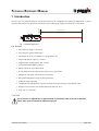
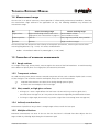
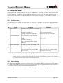
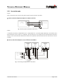
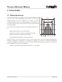
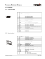
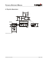
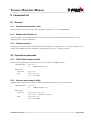
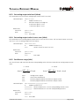
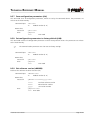
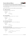
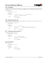
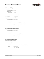
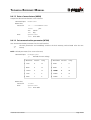
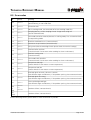
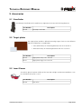
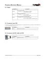
Distance Laser Sensor DLS-A 15 DLS-A 30 DLS-AH 15 DLS-AH 30 Technical Reference Manual V1.06 Please check www.dimetix.com for the latest version Table of Contents 1 Introduction.......................................................................................................................................................3 1.1 Product identification................................................................................................................................4 1.2 Components.............................................................................................................................................4 1.3 Validity......................................................................................................................................................4 1.4 Measurement range..................................................................................................................................5 1.5 Prevention of erroneous measurements....................................................................................................5 2 Device setup......................................................................................................................................................6 2.1 Connection...............................................................................................................................................6 2.2 Controlled mode.......................................................................................................................................7 2.3 Automatic mode.......................................................................................................................................8 3 Installation.......................................................................................................................................................10 3.1 Mounting................................................................................................................................................10 3.2 Device wiring...........................................................................................................................................10 3.3 Alignment of the laser beam...................................................................................................................12 4 Technical data.................................................................................................................................................13 4.1 Measuring accuracy.................................................................................................................................13 4.2 Specifications..........................................................................................................................................14 5 Electrical components......................................................................................................................................15 5.1 ID switch.................................................................................................................................................15 5.2 Reset switch............................................................................................................................................15 5.3 Digital output..........................................................................................................................................15 5.4 Analog output.........................................................................................................................................15 5.5 Connector...............................................................................................................................................16 6 Physical dimensions.........................................................................................................................................17 7 Factory settings................................................................................................................................................18 7.1 Operation................................................................................................................................................18 7.2 Communication parameters....................................................................................................................18 7.3 Analog outputs.......................................................................................................................................18 7.4 Module ID...............................................................................................................................................18 7.5 Digital output 1 (DOUT1).........................................................................................................................18 7.6 Digital output 2 (DOUT2).........................................................................................................................18 8 Command set..................................................................................................................................................19 8.1 General...................................................................................................................................................19 8.2 Operation commands..............................................................................................................................19 8.3 Configuration commands........................................................................................................................21 8.4 Command set for single module operation (Compatibility)......................................................................26 8.5 Error codes..............................................................................................................................................30 9 Accessories......................................................................................................................................................31 9.1 Viewfinder...............................................................................................................................................31 9.2 Target plates...........................................................................................................................................31 9.3 Laser Glasses...........................................................................................................................................31 9.4 Cables.....................................................................................................................................................31 10 Safety instructions.........................................................................................................................................32 10.1 Use of the instrument............................................................................................................................32 10.2 Limits to use..........................................................................................................................................33 10.3 Areas of responsibility...........................................................................................................................33 10.4 Hazards in use.......................................................................................................................................34 10.5 Laser classification.................................................................................................................................35 10.6 Electromagnetic compatibility (EMC).....................................................................................................36 10.7 Labeling................................................................................................................................................37 10.8 Maintenance.........................................................................................................................................38 10.9 Service...................................................................................................................................................38 TECHNICAL REFERENCE MANUAL 1 Introduction Measured distance Target Measuring reference The DLS-A(H) is a powerful distance measuring instrument for integration into industrial applications. It allows accurate and contact-less distance measurement over a wide range using the reflection of a laser beam: Fig. 1 Standard application Key features • Measurement range 0.2 to 200 m • Serial interface (RS232 and RS422) • Connection of up to 10 modules on a single RS422 line • Wide range power supply (9...30VDC) • Programmable analog output (0/4...20mA) • Two programmable digital outputs • Digital output for error signalization • D-Sub connector and screw terminal joint for easy connection • Adapter for telescopic viewer for easy installation • IP65 (protected against ingress of dust and water) • 4 LEDs for status signaling • Complementary configuration software available at Dimetix web site (www.dimetix.com) • Optional: Internal heater for module operation down to -40°C • Laser class II (<0.95mW) CAUTION Use of controls or adjustments or performance of procedures other than those specified herein may result in hazardous radiation exposure. Distance Laser Sensor Page 3/40 TECHNICAL REFERENCE MANUAL 1.1 Product identification The product is identified by the serial label on the top of the enclosure: Version Typical Accuracy 1.5mm 3.0mm Standard version DLS-A 15 Part No.: 500502 DLS-A 30 Part No.: 500501 Extended temperature range DLS-AH 15 Part No.: 500512 DLS-AH 30 Part No.: 500511 1.2 Components 11 1 11 1 10 1 5 6 7 2 8 3 4 5 9 1 Status LEDs status signaling 6 Reset switch resets the DLS-A(H) to default settings 2 15-Pin D-Sub connector RS422, RS232, analog, digital output 7 Screw terminal RS422, RS232, analog, digital output 3 Cable gland (M16 x 1.5mm) for connection cable insertion 8 ID switch defines the module ID for RS422 operation 4 Cab provides access to electrical components 9 Laser beam outlet 10 Receiver optics 5 Mounting area for viewfinder see accessories (Chapter 9 on page 32) 11 Product label see 10.7 Labeling on page 39 1.3 Validity This manual is valid for DLS-A(H) devices with the following software version: Interface software version: Board software version: 0117 or later 0200 To get the software version of the DLS-A use the command described in 8.3.9 Get software version (sNN00N) on page 25 Distance Laser Sensor Page 4/40 TECHNICAL REFERENCE MANUAL 1.4 Measurement range The DLS-A(H) is an optical instrument, whose operation is influenced by environmental conditions. Therefore, the measurement range achieved in the application can vary. The following conditions may influence the measurement range: Key Factors increasing range Factors reducing range Target surface Bright and reflecting surfaces such as the Matt and dark surfaces target plates (See 9 Accessories on page 32) Green and blue surfaces Airborne particles Clean air Dust, fog, heavy rainfall, heavy snowfall Sunshine Darkness Bright sunshine at target The DLS-A(H) does not compensate the influence of atmospheric environment, which may be relevant when measuring long distances (e.g. > 150m). This effects are described in: B.Edlen: “The Refractive Index of Air, Metrologia 2”, 71-80 (1966) 1.5 Prevention of erroneous measurements 1.5.1 Rough surfaces On a rough surface (e.g. coarse plaster), measure against the center of the illuminated area. To avoid measuring to the bottom of plaster joints use a target plate (see accessories) or board. 1.5.2 Transparent surfaces To avoid measuring errors, do not measure towards transparent surfaces such as colorless liquids (such as water) or (dust free) glass. For unfamiliar materials and liquids, always take a trial measurement. ) Erroneous measurements can occur when aiming through panes of glass, or if there are several objects in the line of sight. 1.5.3 Wet, smooth, or high-gloss surfaces 1 Aiming at an “acute“ angle deflects the laser beam. The DLS-A(H) may receive a signal that is too weak (error message 255) or it may measure the distance targeted by the deflected laser beam. 2 If aiming at a right angle, the DLS-A(H) may receive a signal that is too strong (error message 256). 1.5.4 Inclined, round surfaces Measurement is possible as long as there is enough target surface area for the laser spot. 1.5.5 Multiple reflections Erroneous measurements can occur in the case that the laser beam is reflected from other objects than the target. Avoid any reflecting object along the measurement path. Distance Laser Sensor Page 5/40 TECHNICAL REFERENCE MANUAL 2 Device setup We recommend performing the configuration steps in an office before mounting the device, especially if you are not familiar with the DLS-A(H). The DLS-A(H) supports two types of operation modes: • Controlled mode • Automatic mode The first decision to be taken is the type of operation mode that will be used to transmit the distance measurement data. While the controlled mode provides maximum flexibility and accuracy, it is often not suitable for integration into existing PLCs or analog environments. In such cases the automatic mode might be preferred. Key controlled mode automatic mode (with analog output and digital outputs) Accuracy Maximum measurement accuracy Accuracy depends on signal scaling (see 8.3.5 Set distance range (sNv) on page 23) Flexibility Access to full command set Limited Integration Requires protocol implementation Wiring of AO and DO signals Connection Connection of up to 10 DLS-A(H)s to a Point-to-point connection single RS-422 line. The following two sections describe the configuration of the DLS-A(H) for the controlled and automatic modes. 2.1 Connection COM1 or COM2 To be able to configure the DLS-A(H), it must be powered and connected to a PC. Figure shows the necessary connections. On the PC, any terminal program can be used to communicate with the module. Additionally, a configuration utility is available on the web page www.dimetix.com. Tx 3 1 Rx 2 2 Gnd 5 14,15 9 pin D-Sub 7,8 Rx Tx DLS-A(H) GND V+ 15 pin D-Sub Default setting: 19200 Baud: 7 Bit: even Parity: 1 Stop: - + 9..30VDC 24..30VDC for DLS-AH Fig. 2 Connection for DLS-A configuration Distance Laser Sensor Page 6/40 TECHNICAL REFERENCE MANUAL 2.2 Controlled mode In controlled mode, each operation of a DLS-A(H) is triggered by a command sent from a host system over a serial line. While a single device can be connected to the host system using the RS232 interface, up to 10 devices can be connected to a single serial RS422 line. The related command set is described in Chapter 8 on page 19. 2.2.1 Configuration After connecting the module, the steps below are necessary to configure the DLS-A(H) for the controlled interface mode. No. 1 Action Set ID switch Comment Changes of the module ID are activated after a power cycle. Example for module 0: Change the ID Switch to position 0 Set controlled mode Command Set the DLS-A(H) to the controlled mode, if not already in controlled mode. 2 Set ID switch to position 0 Power OFF; Wait 10s; Power ON s0c<trm>1) Example for module 0: Set to controlled mode by the stop command. Set communication parameters 3 If necessary, change the settings for the serial interface. Example for module 0: Set serial interface to 19200 Baud, 8 Bit, no Parity s0br+2<trm>1) Power OFF; Wait 10s; Change settings on the host; Power ON 1) Commands are described in 8 Command set on page 19 Remark: If the communication parameters of the module are lost, please reset the configuration to the factory settings (7 Factory settings on page 18) using the reset button (5.2 Reset switch on page 15). Please note that the ID switch must be reset manually. 2.2.2 Host software Host software is required for operation of the DLS-A(H) in controlled mode. When connecting multiple devices to a single serial line (RS422), strict Master-Slave communication must be implemented (DLS-A(H) operates as slave). Please consult the Dimetix web page for application notes. Careful testing of the host software together with the devices prior to installation is strongly recommended. Distance Laser Sensor Page 7/40 TECHNICAL REFERENCE MANUAL 2.3 Automatic mode The automatic mode is provided for host-less operation of the DLS-A(H). The analog and digitals outputs are updated according the configuration described below as soon as the unit is powered up. Analog Output The analog output is configurable and works with two ranges: – 0..20mA – 4..20mA Digital Outputs Three digital outputs are included in the DLS-A(H). Two are programmable, while the third is used to signal an error state of the device. 2.3.1 Configuration After connecting the module, the following steps are necessary to configure the DLS-A(H) for the automatic mode. No. Action Set current output range Comment Defines if the current output range from 0 to 20mA respectively from 4 to 20mA. 1 Example for module 0: Set current output range from 4mA to 20mA. Set distance range 2 Command Defines minimum distance (Dmin) and the maximum distance (Dmax) for the distance range of the analog output. s0vm+1<trm>1) s0v+00000000+00100000<trm>1) Example for module 0: Set distance range from 0m to 10m Set analog output in error case 3 Sets the current, that should be applied in case of an error. Example for module 0: Set current to 0mA in case of an error. Configure digital output 4 Distance Laser Sensor s0ve+000<trm>1) Set the ON and OFF level for the digital outputs. Example for module 0: DO 1: off=2000mm on=2005mm DO 2: off=4000mm on=4005mm s01+00020000+00020050<trm>1) s02+00040000+00040050<trm>1) Page 8/40 TECHNICAL REFERENCE MANUAL No. Action Save settings Comment The changed configuration must be saved to make it permanent. 5 Example for module 0: Save settings for module 0 Set automatic mode 6 Command s0s<trm>1) Set the DLS-A(H) to the automatic mode with the desired update rate. Example for module 0: Set measurement rate to fastest possible speed. s0A+0<trm>1) 1) Commands are described in 8 Command set on page 19 Remark: If the serial line settings of the module have been lost, please reset the configuration to the factory settings (7 Factory settings on page 18) using the reset button (5.2 Reset switch on page 15). Please note that the ID switch must be reset manually. Distance Laser Sensor Page 9/40 TECHNICAL REFERENCE MANUAL 3 Installation 3.1 Mounting Three M4 threaded holes in the bottom of the DLS-A(H) make it easy to mount the device. Always obey all applicable safety regulations and never use the device outside the specifications stated under 4 Technical data on page 13 3.2 Device wiring 3.2.1 Cable connection A ferrite must be mounted to the connecting cable. Use a ferrite with a impedance of 150 Ω to 260 Ω at 25MHz and 640 Ω to 730 Ω at 100MHz. As example you can use SFC10 from KE Kitagawa. 3.2.2 Shield and Ground The DLS-A(H) contains two electrical isolated grounds, the general ground (GND) and the analog ground (AGND). GND and AGND is connected to the housing by a RC element. Please see figure 3 20nF 15 pin D-Sub 1M 10nF 500k DLS-A(H) GND AGND GND AGND Screw terminal Fig. 3 Connection between shield and ground Distance Laser Sensor Page 10/40 TECHNICAL REFERENCE MANUAL 3.2.3 Controlled mode RS232 When using the RS232 interface only point-to-point communication is possible. ❢ Never connect multiple DLS-A(H)s on a RS232 serial line Host (PC or PLC) Tx 1 Rx Rx 2 Tx DLS-A(H) 9..30VDC 24..30VDC for DLS-AH 7,8 V+ 14,15 0V Fig. 4 Point-to-point connection with RS232 RS422 It is possible to connect multiple devices on a single RS422 line. To ensure proper operation, strict Master-Slave communication must be used. It is important, that the Master has full control of the communication and never initiates a new communication before termination of the previous communication (answer from the DLS-A(H) or timeout). ❢ Ensure, that all DLS-A(H)s are set to different ID numbers Host (PC or PLC) (master) A B Rt A B Rt V+ 7,8 14,15 T+ T4 Rt 3 R+ R5 6 V+ 7,8 14,15 T+ T4 3 R+ R5 7,8 14,15 3 5 6 (slave) ID switch Position 9 V+ ID switch Position 1 T+ T- ID switch Position 0 4 DLS-A(H) (slave) R+ R- DLS-A(H) (slave) 6 DLS-A(H) Rt 9..30VDC 24..30VDC for DLS-AH 0V Fig. 5 Connecting multiple devices with RS422 Distance Laser Sensor Page 11/40 TECHNICAL REFERENCE MANUAL 3.2.4 Automatic mode The analog interface of the DLS-A(H) is isolated from the rest of the device. When using the analog interface, connect the analog ground (AGND). Make sure, that the total resistance in the analog path is smaller than 500 Ω. 13 DLS-A(H) 12 9 10 7,8 14,15 AO Analog Input 0..20mA AGND PLC 24V= DO 1 DO 2 V+ GND Digital Input 9..30VDC 24..30VDC for DLS-AH 0V Fig. 6 Connection of an instrument and a PLC 3.3 Alignment of the laser beam Alignment of the laser beam is often difficult when the target is far away, as the laser spot is not visible. The DLS-A(H) has an adapter for mounting a telescopic viewfinder that simplifies alignment significantly. Please refer to chapter 9 Accessories on page 32 for a description of the viewfinder. Distance Laser Sensor Page 12/40 TECHNICAL REFERENCE MANUAL 4 Technical data 4.1 Measuring accuracy The measuring accuracy corresponds to the ISO-recommendation ISO/R 1938-1971 with a statistical confidence level of 95.4% (i.e. ± twice the standard deviation σ, refer to diagram on the right). The typical measuring accuracy relates to average conditions for measuring. It is ±1.5mm for the DLS-A(H) 15 and ± 3.0mm for the DLS-A(H) 30 valid in the tracking mode 99.7% 95.4% The maximum measuring error relates to unfavorable conditions such as: - Highly reflecting surfaces (e.g. reflector tapes) - Operation at the limits of the permitted temperature range, adaptation to ambient temperature interrupted - Very bright ambient conditions, strong heat shimmer and can be up to ± 2 mm for DLS-A(H) 15 and ± 5 mm for DLS-A(H) 30. The DLS-A(H) does not compensate changes of atmospheric environment. This changes can influence the accuracy if measuring long distances (>150m) at conditions very different to 20°C, 60% relative humidity and 953 mbar air pressure. The influences of the atmospheric environment is described in B.Edlen: “The Refractive Index of Air, Metrologia 2”, 71-80 (1966) Distance Laser Sensor Page 13/40 TECHNICAL REFERENCE MANUAL 4.2 Specifications Typical measuring accuracy for DLS-A 15 / DLS-AH 15 1) DLS-A 30 / DLS-AH 30 1) Maximum measuring accuracy for DLS-A 15 / DLS-AH 15 1) DLS-A 30 / DLS-AH 30 1) Smallest unit displayed Measuring range on natural surfaces Measuring range on brown (reflecting) target plate Measuring reference Diameter of laser spot at target at a distance of Time for a measurement Single measurement Tracking Light source Laser Life Time 3) ESD EMC Power supply Dimensions Temperature range during operation 2) DLS-A 15 / DLS-A 30 DLS-AH 15 / DLS-AH 30 Temperature range during storage Degree of Protection Weight Interface ± 1.5 mm @ 2s ± 3.0 mm @ 2s ± 2.0 mm ± 5.0 mm 0.1 mm 0.2 to 30 m ca. 20 to 200 m from front edge (See 6 Physical dimensions) 6mm @ 10 m 30mm @ 50 m 60mm @ 100 m 0.6 to ca. 5 sec 0.6 to ca. 5 sec Laser diode 620-690 nm (red) IEC 60825-1:2001; Class 2 FDA 21CFR 1040.10 and 1040.11 Beam divergence:0.16 x 0.6 mrad Pulse duration: 15x10-9 s Maximum radiant power: 0.95 mW Maximum radiant power per pulse: 8mW Measurement uncertainty: ±5% >25'000h @ 25°C IEC 61000-4-2 : 1995 EN 61000-6-4 EN 61000-6-2 9 ... 30V DC 0.5A for DLS-A 24 ... 30V DC 2.5A for DLS-AH (Heating option) 150 x 80 x 55 mm -10 °C to +50 °C -40 °C to +50 °C -40 °C to +70 °C IP65; IEC60529 (protected against ingress of dust and water) DLS-A: 630 g DLS-AH: 680 g 1 serial asynchronous interface (RS232/RS422) 1 programmable analog output 0/4 .. 20mA 2 programmable digital outputs 1 digital output for error status 1 ) See 4.1 Measuring accuracy on page 13. ) In case of permanent measurement (tracking mode) the max. temperature is reduced to 45°C 3 ) 500 – 1000h at 50°C. 2 Distance Laser Sensor Page 14/40 TECHNICAL REFERENCE MANUAL 5 Electrical components 5.1 ID switch This switch is used to set the module ID and can be set from 0 to 9. 5.2 Reset switch To reset the module to factory settings do the following: • Switch OFF the power for the module • Press the reset button and keep it pressed • Switch on the power for the module • Keep the reset button pressed until all LEDs on the module are illuminated • Release the reset button and wait until the green power LED is on 5.3 Digital output DOUT On Fig. 7 Open drain output The DLS-A(H) contains two digital outputs for level monitoring (DO 1 and DO 2) and one digital output for error signalization (DO E). These outputs are open drain outputs as shown in figure 7 and can drive up to 200mA. In the ON state, the FET transistor is electroconductive. 5.4 Analog output The analog output of the DLS-A(H) is a current source (0..20mA or 4..20mA). It is capable of driving loads up to 500Ω. The analog output has an accuracy of +/- 1% Full scale. Distance Laser Sensor Page 15/40 TECHNICAL REFERENCE MANUAL 5.5 Connector 5.5.1 D-Sub connector Pin 15 8 9 1 Designator Description 1 Rx RS232 receive line 2 Tx RS232 send line 3 T- RS422 send line negative 4 T+ RS422 send line positive 5 R- RS422 receive line negative 6 R+ RS422 receive line positive 7 PWR 8 PWR DC Power + 9V…+30V for DLS-A +24V…+30V for DLS-AH (Heating option) 9 DO 1 Digital output 1 (Open Drain) 10 DO 2 Digital output 2 (Open Drain) 11 DO E Digital output for error signalization (Open Drain) 12 AGND Analog ground 13 AO Analog output (0/4..20mA) 14 GND Ground line 15 GND Ground line Designator Description 1 R+ RS422 Receive line positive 2 R- RS422 Receive line negative 3 T+ RS422 Send line positive 4 T- RS422 Send line negative 5 Tx RS232 Transmit line 6 Rx RS232 Receive line 7 AGND Analog ground 8 AO Analog output (0/4..20mA) 9 DO E Digital output for error signalization (Open Drain) 10 DO 2 Digital output 2 (Open Drain) 11 DO 1 Digital output 1 (Open Drain) 12 GND Ground line 13 PWR Power DC +9V...+30V DLS-A +24...+30V DLS-AH (Heating option) 5.5.2 Screw terminal Pin No.1 Distance Laser Sensor Page 16/40 TECHNICAL REFERENCE MANUAL 6 Physical dimensions 88.5 40.0 = = 80.0 = = 38.5 3 x M4 x 5 150.0 M16 x 1.5 152.5 34.2 53.0 10.5 Laser Beam Measuring reference 33.3 17 80.0 All dimension in mm Distance Laser Sensor Page 17/40 TECHNICAL REFERENCE MANUAL 7 Factory settings 7.1 Operation Mode: Controlled 7.2 Communication parameters Baud: Data bit: Parity: Stop bit: 19200 7 Even 1 7.3 Analog outputs Min output: Range min: Range max: Error output: 4mA 0m 10m 0mA 7.4 Module ID ID Number: 0 7.5 Digital output 1 (DOUT1) ON: OFF: 2m + 5mm = 2005mm 2m - 5mm = 1995mm 7.6 Digital output 2 (DOUT2) ON: OFF: Distance Laser Sensor 1m – 5mm = 995mm 1m + 5mm = 1005mm Page 18/40 TECHNICAL REFERENCE MANUAL 8 Command set 8.1 General 8.1.1 Command termination <trm> All commands for the DLS-A(H) are ASCII based and terminated <trm> with <cr><lf>. 8.1.2 Module identification N Since the module can be addressed with the ID switch, the ID is represented in the commands by N. On the location of the N insert the Module ID. 8.1.3 Startup sequence After power on the DLS-A does all the initializations and sends a start sequence gN?. On these sequence, the N stands for the Module ID. After sending this start sequence, the DLS-A is ready to measure. 8.2 Operation commands 8.2.1 STOP/CLEAR command (sNc) Stops the current execution and resets the status LEDs as well as the digital outputs. Command input: Return data Successful: Error: sNc<trm> N: Module number (0..9) gN?<trm> gN@Ezzz<trm> zzz: Error code 8.2.2 Distance measurement (sNg) Triggers simple measurement of distance. Each new command cancels an active measurement. Command input: Return data Successful: Error: Distance Laser Sensor sNg<trm> N: Module number (0..9) gNg+xxxxxxxx<trm> xxxxxxxx: Distance in 1/10 mm gN@Ezzz<trm> zzz: Error code Page 19/40 TECHNICAL REFERENCE MANUAL 8.2.3 Temperature measurement (sNt) Triggers measurement of temperature. Command input: Return data Successful: Error: sNt<trm> N: Module number (0..9) gNt+xxxxxxxx<trm> +xxxxxxxx: temperature in 1/10°C gN@Ezzz<trm> zzz: Error code 8.2.4 Laser ON (sNo) Switches laser ON. Command input: Return data Successful: Error: sNo<trm> N: Module number (0..9) gN?<trm> gN@Ezzz<trm> zzz: Error code 8.2.5 Laser OFF (sNp) Switches laser OFF. Command input: Return data Successful: Error: Distance Laser Sensor sNp<trm> N: Module number (0..9) gN?<trm> gN@Ezzz<trm> zzz: Error code Page 20/40 TECHNICAL REFERENCE MANUAL 8.2.6 Tracking with buffering – Start (sNf) Triggers continuous measurement of the distance with internal buffering in the module (buffer for one measurement). The rate of measurements is defined with the sampling time. If the sampling time is set to zero, the measurements are executed as fast as possible. The last measurement can be read out from the module with the command sNq. The measurements are continued until the 'sNc' command is issued. Command input: Return data Successful: Error: sNf+xxxxxxxx<trm> N: Module number (0..9) xxxxxxxx: Samplling time in 10 ms (if 0 -> max possible rate) gNf?<trm> gN@Ezzz<trm> zzz: Error code 8.2.7 Tracking with buffering - Read out (sNq) After starting “tracking with buffering” with the command sNf, the last measurement can be read out from the module with the command sNq. Command input: Return data Successful: Error: Distance Laser Sensor sNq<trm> N: Module number (0..9) gNq+xxxxxxxx+c<trm> xxxxxxxx: Distance in 1/10 mm c: 0 = no new measurement since last sNq command 1 = new measurement since last sNq command, not overwritten 2 = new measurement since last sNq command, overwritten gN@Ezzz+c<trm> zzz: Error code c: see above Page 21/40 TECHNICAL REFERENCE MANUAL 8.3 Configuration commands 8.3.1 Set communication parameter (sNbr) Sets the communication parameters for the serial interface. The new parameters are immediately saved to the Flash Memory and activated after the power ON. Bold = default parameters (first use or after reset) ) Command input: sNbr+y<trm> N: Module number (0..9) y: Defines the new settings % Baud rate Data bit Parity % Baud Rate Data bit Parity 0 1200 8 N 5 4800 7 E 1 9600 8 N 6 9600 7 E 2 19200 8 N 7 19200 7 E 3 1200 7 E 8 38400 8 N 4 2400 7 E 9 38400 7 E Return data Successful: Error: gN?<trm> gN@Ezzz<trm> zzz: Error code 8.3.2 Set automatic mode (sNA) This command activates the automatic mode of the DLS-A(H). It triggers continuous measurement of the distance and sets the analog and digital outputs according to the measured distance values. The rate of measurements is defined with the sampling time. If the sampling time is set to zero, the measurements are executed as fast as possible. The automatic mode is active until the 'sNc' command is issued. ) The operation mode is stored in the DLS-A(H) and activated immediately. This mode is also activated after next power ON. ) Internally “tracking with buffering” is started (command sNf). Therefore the last measurement can also be read out from the module with the command sNq. Command input: Return data Successful: Error: Distance Laser Sensor sNA+xxxxxxxx<trm> N: Module number (0..9) xxxxxxxx: Sampling time in 10 ms (if 0 -> max possible rate) gNA?<trm> gN@Ezzz<trm> zzz: Error code Page 22/40 TECHNICAL REFERENCE MANUAL 8.3.3 Set analog output min level (sNvm) This command sets the minimum analog output current level (0 or 4 mA). Command input: sNvm+x<trm> N: Module number (0..9) x: Minimum output for analog out 0: Minimum signal is 0 mA 1: Minimum signal is 4 mA Return data: Successful: Error: gNvm?<trm> gN@Ezzz zzz: Error code 8.3.4 Set analog output value in error case (sNve) This command sets the analog output current level in mA in case of an error. This level can be lower as the min level set in 8.3.3 Set analog output min level (sNvm). Command input: Return data: Successful: Error: sNve+xxx<trm> N: Module number (0..9) xxx: Value in case of an error in 0.1mA gNve?<trm> gN@Ezzz zzz: Error code 8.3.5 Set distance range (sNv) Sets the minimum and maximum distances corresponding to the minimum and maximum analog output current levels. 0...20mA Aout= DIST D min ∗20 mA D max D min Aout DIST Dmin Dmax Command input: Return data: Successful: Error: Distance Laser Sensor 4...20mA Aout = DIST D min ∗16 mA4 mA D max D min Analog current output Actual measured distance Distance programmed for the minimum output current Distance programmed for the maximum output current sNv+xxxxxxxx+yyyyyyyy<trm> N: Module number (0..9) xxxxxxxx: Minimum distance in 1/10 mm corresponding to 0mA / 4mA yyyyyyyy: Maximum distance in 1/10 mm corresponding to 20mA gNv?<trm> gN@Ezzz zzz: Error code Page 23/40 TECHNICAL REFERENCE MANUAL 8.3.6 Set digital output levels (sNn) Sets the distance levels at which the digital outputs are switched ON and OFF with a hysteresis. Two different situations are possible: ON level > OFF level DO The ON level of the hysteresis is larger than the OFF level. With an increasing distance, the digital output is switched on (open drain output is closed) when the distance exceeds the ON level. With a decreasing distance, the digital output is switched off (open drain output is open) when the distance falls below the OFF level. closed open Distance 0 Off On ON level < OFF level The ON level of the hysteresis is smaller than the OFF level. With a decreasing distance, the digital output is switched on (open drain output is closed) when the distance falls below the ON level. With an increasing distance, the digital output is switched off (open drain output is open) when the distance exceeds the OFF level. DO closed open Distance 0 On Command input: Return data: Successful: Error: Distance Laser Sensor Off sNn+xxxxxxxx+yyyyyyyy<trm> N: Module number (0..9) n: Digital output port (1 or 2) xxxxxxxx: Distance ON level in 1/10 mm for switching digital output ON yyyyyyyy: Distance OFF level in 1/10 mm for switching digital output OFF gNn?<trm> gN@Ezzz zzz: Error code Page 24/40 TECHNICAL REFERENCE MANUAL 8.3.7 Save configuration parameters (sNs) This command saves all configuration parameters, which are set by the commands above. The parameters are written to the Flash Memory. Command input: Return data: Successful: Error: sNs<trm> N: Module number (0..9) gNs?<trm> gN@Ezzz zzz: Error code 8.3.8 Set configuration parameters to factory default (sNd) This command restores all configuration parameters to their factory default values. The parameters are written to the Flash Memory. ) The communication parameters are also reset to factory settings. Command input: Return data: Successful: Error: sNd<trm> N: Module number (0..9) gN?<trm> gN@Ezzz zzz: Error code 8.3.9 Get software version (sNN00N) Retrieves the software version of the DLS-A(H). Command input: Return data Successful: Error: Distance Laser Sensor sNN00N<trm> N: Module number (0..9) gNN00N+vvvvxxxxyyyy<trm> vvvv: Interface software version xxxx: Board version number yyyy: SW version number gN@Ezzz<trm> zzz: Error code Page 25/40 TECHNICAL REFERENCE MANUAL 8.3.10 Get hardware version (sNN01N) Retrieves the hardware version of the DLS-A(H). Command input: Return data Successful: Error: sNN01N<trm> N: Module number (0..9) gNN01N+xxxxxxyy<trm> xxxxxx: Board number yy: Revision index gN@Ezzz<trm> zzz: Error code 8.3.11 Get serial number (sNN02N) Retrieves the serial number of the DLS-A(H). Command input: Return data Successful: Error: sNN02N<trm> N: Module number (0..9) gNN02N+xxxxxxxx<trm> xxxxxx: Serial number of the device gN@Ezzz<trm> zzz: Error code 8.3.12 Get date of manufacture (sNN03N) Retrieves the date of manufacture of the DLS-A(H). Command input: Return data Successful: Error: Distance Laser Sensor sNN03N<trm> N: Module number (0..9) gNN03N+YYYYMMDD<trm> YYYY: year MM: month DD: day gN@Ezzz<trm> zzz: Error code Page 26/40 TECHNICAL REFERENCE MANUAL 8.4 Command set for single module operation (Compatibility) The commands described in this chapter are compatible with commands form the DISTO OEM Module 3.0. These commands only work properly for point-to-point connections of the serial interface from the module to the PC or any other controller. ❢ Never use these commands if more than one module is connected to the RS422 line 8.4.1 RESET command (a) Resets the module, the status LEDs and the digital outputs. Command input: Return data Successful: Error: a<trm> ?<trm> @Ezzz<trm> zzz: Error code 8.4.2 OFF command (b) Switches the module Off. To switch the module On, use the “a” command. Command input: Return data Successful: Error: b<trm> ?<trm> @Ezzz<trm> zzz: Error code 8.4.3 STOP/CLEAR command (c) Stops the current execution and resets the status LEDs as well as the digital outputs. Command input: Return data Successful: Error: c<trm> ?<trm> @Ezzz<trm> zzz: Error code 8.4.4 Distance measurement (g) Triggers simple measurement of the distance. Each new command cancels an active measurement. The status LEDs and the digital outputs are updated corresponding to the new measured distance. Command input: Return data Successful: Error: Distance Laser Sensor g<trm> 31..06+xxxxxxxx 51....+00000000<trm> xxxxxxxx: Distance in 1/10 mm @Ezzz<trm> zzz: Error code Page 27/40 TECHNICAL REFERENCE MANUAL 8.4.5 Tracking (h) Triggers continuous measurement of the distance. The measurements are continued until the next command is issued or until a fault arises. The status LEDs and the digital outputs are updated corresponding to the new measured distance. Command input: Return data Successful: Error: h<trm> 31..06+xxxxxxxx 51....+00000000<trm> xxxxxxxx: Distance in 1/10 mm @Ezzz<trm> zzz: Error code 8.4.6 Signal measurement (k) Triggers continuous measurement of the signal strength. The measurements are continued until the next command is received or until a fault arises. Command input: Return data Successful: Error: k<trm> 53....+xxxxxxxx<trm> xxxxxxxx: Signal strength of the returned light in mV @Ezzz<trm> zzz: Error code 8.4.7 Temperature measurement (t) Triggers measurement of temperature. Command input: Return data Successful: Error: t<trm> 40....+xxxxxxxx<trm> xxxxxxxx: temperature in 1/10°C @Ezzz<trm> zzz: Error code 8.4.8 Laser ON (o) Switches laser ON. Command input: Return data Successful: Error: Distance Laser Sensor o<trm> ?<trm> @Ezzz<trm> zzz: Error code Page 28/40 TECHNICAL REFERENCE MANUAL 8.4.9 Laser OFF (p) Switches laser OFF. Command input: Return data Successful: Error: p<trm> ?<trm> @Ezzz<trm> zzz: Error code 8.4.10 Software version (N00N) Outputs software version at interface. Command input: Return data Successful: Error: N00N<trm> 13....+xxxxyyyy<trm> xxxx: Board version number yyyy: SW version number @Ezzz<trm> zzz: Error code 8.4.11 Hardware version (N01N) Outputs the hardware version at the interface. Command input: Return data Successful: Error: N01N<trm> 14....+xxxxxxyy<trm> xxxxxx: Board number yy: Revision index @Ezzz<trm> zzz: Error code 8.4.12 Serial number (N02N) Outputs serial number at interface. Command input: Return data Successful: Error: Distance Laser Sensor N02N<trm> 12....+xxxxxxxx<trm> xxxxxx: Serial number of the device @Ezzz<trm> zzz: Error code Page 29/40 TECHNICAL REFERENCE MANUAL 8.4.13 Date of manufacture (N03N) Outputs the date of manufacture at the interface. Command input: Return data Successful: Error: N03N<trm> 15....+YYYYMMDD<trm> YYYY: year MM: month DD: day @Ezzz<trm> zzz: Error code 8.4.14 Set communication parameter (N70N) Sets the communication parameters for the serial interface. ) The new parameters are immediately saved to the Flash Memory and activated after the next startup. Bold = default parameters (first use or after reset) Command input: N70NyN<trm> y: Defined the new settings % Baud rate Data bit Parity % Baud Rate Data bit Parity 0 1200 8 N 5 4800 7 E 1 9600 8 N 6 9600 7 E 2 19200 8 N 7 19200 7 E 3 1200 7 E 8 38400 8 N 4 2400 7 E 9 38400 7 E Return data Successful: Error: Distance Laser Sensor ?<trm> @Ezzz<trm> zzz: Error code Page 30/40 TECHNICAL REFERENCE MANUAL 8.5 Error codes No. Format Meaning 203 @E203 wrong syntax in command, or prohibited command, or prohibited parameter in command entry, or non-valid result 204 @E204 Dimension error 210 @E210 Not in tracking mode, use command sNf to start tracking mode first. 211 @E211 Sampling too fast, set the sampling time to a larger value using sNf (also for command sNA) 212 @E212 Command cannot be executed, because in tracking mode, first use command sNc to stop tracking mode. 213 @E213 Baud rate could not be set. (Contact Dimetix) 217 @E217 Parameter set-up incorrect (Contact Dimetix) 221 @E221 Parity error (Prior to contacting Dimetix please check the Terminal settings) 222 @E222 Interface buffer overflow (Contact Dimetix if error occurs when sending less than 24 characters) 223 @E223 Interface framing error (Contact Dimetix) 224 @E224 Command buffer overflow (Contact Dimetix if error occurs when sending less than 24 characters) 252 @E252 Temperature too high (contact Dimetix if error occurs at room temperature) 253 @E253 Temperature too low (contact Dimetix if error occurs at room temperature) 255 @E255 Received signal too weak, distance < 200mm (Use different target and distances, if the problem persists, please contact Dimetix) 256 @E256 Received signal too strong (Use different target and distances, if the problem persists, please contact Dimetix) 257 @E257 Too much background light (Use different target and distances, if the problem persists, please contact Dimetix) 260 to 299 @E260 to @E299 Hardware failure (Contact Dimetix) not listed Hardware failure (Contact Dimetix) Before contacting Dimetix, please collect as much information as possible. Distance Laser Sensor Page 31/40 TECHNICAL REFERENCE MANUAL 9 Accessories 9.1 Viewfinder The telescopic viewfinder can be used for easy alignment of the DLS-A(H) for long distances. Part Number Description 500100 Telescopic viewfinder 9.2 Target plates The target plates provide a defined measuring target. Please use the different sides for the distances as stated below: • Front color brown, for measuring distances from 20 m to 200 m • Back color white, for measuring distances from 0.2 m to 30 m Part Number Description 500110 Target plate small, 105 x 147 mm 500111 Target plate large, 210 x 297 mm 9.3 Laser Glasses The red lens glasses improve visibility of the laser dot at bright environment conditions. It can be use for distances up to 10-15m. Part Number 500120 Distance Laser Sensor Description Laser Glass Page 32/40 TECHNICAL REFERENCE MANUAL 9.4 Cables Part Number Description 500200 PC-Connection cable: DLS-A(H) to - 9 pin D-Sub for PC (RS232) - 2 wires for power supply 500201 RS422-Connection cable: DLS-A(H) to - 5 wires for RS422 - 2 wires for power supply 500202 Connection cable for automatic mode: DLS-A(H) to - 2 wires for current output - 5 wires for digital outputs and power supply 9.5 Connector cover IP65 If the DLS-A is connected via the cable gland and the 15 pin D-Sub connector is not used, this cover protects the 15 pin D-Sub connector of the DLS-A. Part Number 500251 Description Connector Cover IP65 9.6 Connector with 90° cable exit IP65 The connector allows the connection of the DLS-A with IP65 protection. Part Number 500253 Distance Laser Sensor Description Connector 90° IP65 Page 33/40 TECHNICAL REFERENCE MANUAL 10 Safety instructions The following directions should enable the person responsible for the DLS-A(H), and the user of the instrument, to anticipate and avoid operational hazards. The DLS-A(H) is made to be integrated into technical systems. A basic technical education is therefore essential. This device may only be operated by trained persons. The person responsible for the instrument must ensure that all users understand these directions and adhere to them. If the DLS-A(H) is part of a system, the manufacturer of such a system is responsible for all safety-relevant issues, such as the manual, labeling and instruction. 10.1 Use of the instrument Permitted use: The permitted use of the DLS-A(H) is: measuring distances. Prohibited use: 1) Using the instrument without instruction 2) Using outside the stated limits 3) Deactivation of safety systems and removal of explanatory and hazard labels 4) Opening of the equipment, except to open the cover for access to the screw terminal 5) Carrying out modification or conversion of the product 6) Operation after failure in operation 7) Use of accessories from other manufacturers without the express approval of Dimetix. 8) Aiming directly into the sun 9) Deliberate dazzling of third parties; also in the dark 10) Inadequate safeguards at the surveying site (e.g. when measuring on roads, etc.) WARNING Prohibited use can lead to injury, malfunction, and material damage. It is the duty of the person responsible for the instrument to inform the user about hazards and how to counteract them. The DLS-A(H) must not be operated until the user has been adequately instructed. Distance Laser Sensor Page 34/40 TECHNICAL REFERENCE MANUAL 10.2 Limits to use ) See section ”Technical Data” Environment: Suitable for use in an atmosphere appropriate for permanent human habitation. Cannot be used in an aggressive or explosive environment. 10.3 Areas of responsibility Responsibilities of the manufacturer of the original equipment Dimetix AG, CH-9100 Herisau (Dimetix): Dimetix is responsible for supplying the product, including the Technical Reference Manual and original accessories, in a completely safe condition. Responsibilities of the manufacturer of non-Dimetix accessories: The manufacturers of non-Dimetix accessories for the DLS-A(H) are responsible for developing, implementing and communicating safety concepts for their products. They are also responsible for the effectiveness of these safety concepts in combination with the Dimetix equipment. Responsibilities of the person in charge of the instrument: WARNING: The person responsible for the instrument must ensure that the equipment is used in accordance with the instructions. This person is also accountable for the deployment of personnel and for their training and for the safety of the equipment when in use. The person in charge of the instrument has the following duties: 1) To understand the safety instructions of the product and the instructions in the Technical Reference Manual. 2) To be familiar with local safety regulations relating to accident prevention. 3) To inform Dimetix immediately if the equipment becomes unsafe. Distance Laser Sensor Page 35/40 TECHNICAL REFERENCE MANUAL 10.4 Hazards in use Important hazards in use WARNING: The absence of instruction, or the inadequate imparting of instruction, can lead to incorrect or prohibited use, and can give rise to accidents with far-reaching human, material and environmental consequences. Precautions: All users must follow the safety instructions given by the manufacturer and the directions of the person responsible for the instrument. CAUTION: Watch out for erroneous distance measurements if the instrument is defective or if it has been dropped or has been misused or modified. Precautions: Carry out periodic test measurements, partially after the instrument has been subject to abnormal use, and before, during and after important measurements. Make sure the DLS-A(H) optics are kept clean. WARNING: Hidden labels of the DLS-A(H) when mounted could cause a dangerous situation. Precautions: Always ensure the visibility of DLS-A(H) labels at all times or add labels corresponding to the local safety regulation. CAUTION: When using the instrument for distance measurements or for positioning moving objects (e.g. cranes, building equipment, platforms, etc.) unforeseen events (e.g. breaking the laser beam) may cause erroneous measurements. Precautions: Only use this product as a measuring sensor, not as a control device. The system must be configured and operated in such a way that no damage will occur in case of an erroneous measurement, malfunction of the device or power failure due to installed safety measures (e.g. safety limit switch). Distance Laser Sensor Page 36/40 TECHNICAL REFERENCE MANUAL WARNING: Operate the equipment appropriately in accordance with the regulations in force. Always prevent access to the equipment by unauthorized personnel. CAUTION: Be careful when pointing a telescope towards the sun, because the telescope functions as a magnifying glass and can injure eyes and/or cause damage inside the DLS-A(H). Precautions: Do not point the telescope directly at the sun. 10.5 Laser classification The DLS-A(H) produces a visible laser beam, which emerges from the front of the instrument. It is a Class 2 laser product in accordance with: 1) IEC60825-1 (2001) ”Radiation safety of laser products” 2) EN60825-1 (2001) ”Radiation safety of laser products” It is a Class II laser product in accordance with: 1) FDA 21CFR 1040.10 1004.11 (US Department of Health and Human Service, Code of Federal Regulations) Laser Class 2/II products: Do not stare into the laser beam or direct it towards other people unnecessarily. Eye protection is normally afforded by aversion responses including the blink reflex. WARNING: Looking directly into the beam with optical aids (binoculars, telescopes) can be hazardous. Precautions: Do not look into the laser beam. Make sure the laser is aimed above or below eye level. (particularly with fixed installations, in machines, etc.). Distance Laser Sensor Page 37/40 TECHNICAL REFERENCE MANUAL CAUTION: Looking into the laser beam may be hazardous to the eyes. Precautions: Do not look into the laser beam. Make sure the laser is aimed above or below eye level (particularly with fixed installations, in machines, etc.). 10.6 Electromagnetic compatibility (EMC) The term ”electromagnetic compatibility” is taken to mean the capability of the DLS-A(H) to function smoothly in an environment where electromagnetic radiation and electrostatic discharges are present, and without causing electromagnetic interference to other equipment. WARNING: Electromagnetic radiation can cause interference in other equipment. Although the DLS-A(H) meets the strict regulations and standards that are in force in this respect, Dimetix cannot completely exclude the possibility that interference may be caused to other equipment. Distance Laser Sensor Page 38/40 TECHNICAL REFERENCE MANUAL 10.7 Labeling LASER RADIATION DO NOT STARE INTO BEAM CLASS 2 LASER PRODUCT 620-690nm 0.95mW max. Class 2 Laser Product Complies with 21CFR 1040.10 and 1040.11 except for deviations pursuant to Laser Notice no.50, dated May 2001, with IEC 60825-1 (2001) and EN 60825-1 (2001) Dimetix AG CH-9100 Herisau WWW.DIMETIX.COM Made in Switzerland DLS-A 30 Type: Part No.: 123456 Serial No.: 123456 Manufactured: Rx Tx TT+ RR+ RS232 RS422 Emitted wavelength 620-690nm Beam divergence 0.16 x 0.6 mrad Pulse duration -9 15x10 s Max. radiant power* 0.95 mW Measurement uncertainty ±5% Max. radiant power per pulse 8 mW 03/2003 DO 2 DO 1 15 8 1 2 3 4 5 6 EN60825-1:2001 IEC60825-1:2001 9..30V / 0.5A= Error Power Power: Standard applied 9 1 7 8 9 10 11 V+ V+ DO 1 DO 2 DO E (Error) 12 13 14 15 AGND AO GND GND Fig. 8 The label is applied on the top of the device Distance Laser Sensor Page 39/40 TECHNICAL REFERENCE MANUAL 10.8 Maintenance The DLS-A(H) is almost maintenance free. The only thing you have to do is cleaning the optical surfaces. CAUTION: Look after the optical surfaces with same care that you would apply to spectacles, cameras and field glasses. 10.9 Service If you need to service the device, please contact Dimetix for instructions. Dimetix AG Degersheimerstr. 14 CH-9100 Herisau Switzerland © Copyright by Dimetix 2004 Tel. + 41–71–383 20 10 Fax + 41–71–383 20 11 Email [email protected] www.dimetix.com Distance Laser Sensor Page 40/40