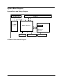
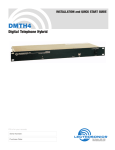
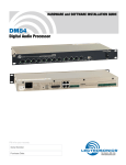
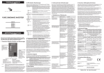
1
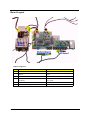
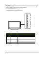
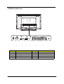
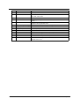
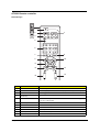
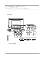
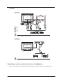
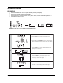
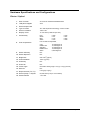
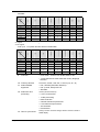
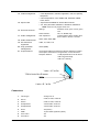
Acer AT3220A/3220B/3220 LCD TV
Service Guide
Service guide files and updates are available
on the ACER/CSD web; for more information,
please refer to http://csd.acer.com.tw
Project Code: T58
PRINTED IN TAIWAN
Revision History
Please refer to the table below for the updates made on Acer LCD TV AT3220/3220A/3220B service guide.
Date
2006/08/08
II
Chapter
Chapter 1
Updates
Revise PIP/PBP/POP supporting configuration on page 37.
Copyright
Copyright © 2006 by Acer Incorporated. All rights reserved. No part of this publication may be reproduced,
transmitted, transcribed, stored in a retrieval system, or translated into any language or computer language, in
any form or by any means, electronic, mechanical, magnetic, optical, chemical, manual or otherwise, without
the prior written permission of Acer Incorporated.
Disclaimer
The information in this guide is subject to change without notice.
Acer Incorporated makes no representations or warranties, either expressed or implied, with respect to the
contents hereof and specifically disclaims any warranties of merchantability or fitness for any particular
purpose. Any Acer Incorporated software described in this manual is sold or licensed "as is". Should the
programs prove defective following their purchase, the buyer (and not Acer Incorporated, its distributor, or its
dealer) assumes the entire cost of all necessary servicing, repair, and any incidental or consequential
damages resulting from any defect in the software.
Acer is a registered trademark of Acer Corporation.
Other brand and product names are trademarks and/or registered trademarks of their respective holders.
III
Conventions
The following conventions are used in this manual:
IV
SCREEN MESSAGES
Denotes actual messages that appear
on screen.
NOTE
Gives bits and pieces of additional
information related to the current
topic.
WARNING
Alerts you to any damage that might
result from doing or not doing specific
actions.
CAUTION
Gives precautionary measures to
avoid possible hardware or software
problems.
IMPORTANT
Reminds you to do specific actions
relevant to the accomplishment of
procedures.
Preface
Before using this information and the product it supports, please read the following general information.
1.
This Service Guide provides you with all technical information relating to the BASIC CONFIGURATION
decided for Acer's "global" product offering. To better fit local market requirements and enhance product
competitiveness, your regional office MAY have decided to extend the functionality of a machine (e.g.
add-on card, modem, or extra memory capability). These LOCALIZED FEATURES will NOT be covered
in this generic service guide. In such cases, please contact your regional offices or the responsible
personnel/channel to provide you with further technical details.
2.
Please note WHEN ORDERING FRU PARTS, that you should check the most up-to-date information
available on your regional web or channel. If, for whatever reason, a part number change is made, it will
not be noted in the printed Service Guide. For ACER-AUTHORIZED SERVICE PROVIDERS, your Acer
office may have a DIFFERENT part number code to those given in the FRU list of this printed Service
Guide. You MUST use the list provided by your regional Acer office to order FRU parts for repair and
service of customer machines.
V
VI
Chapter 1
System Specifications
Features
This LCD TV was designed with the user in mind. Here are just a few of its many features:
LCD Panel
T
Max. resolution: 1366x768
T
Display area: 32 inches diagonal
T
Display color: 16.7 M colors (8 real bits per color)
T
Life time: 60,000 hours
T
Input Signal: 1-ch LVDS
T
Contrast ratio: 1200:1 ( Typ )
T
Brightness: 200 cd/m2 ( Typ )
T
Response Time: AUO Typ. Gray to gray Tr=Tf=8ms
T
Viewing angle: 176 ° ( L ) / 176 ° ( R ), 176 ° ( U ) / 176 ° ( D)
I/O Functions
T
RCA jack (YUV and CVBS) for YPbPr, YCbCr, video and audio
T
Support 480i/576i, 480p/576p, 1080i and 720p format
T
Built-in dynamic adaptive smoothing filter
T
Built-in dynamic temporal frame-filtering noise reduction
T
Built-in dynamic motion and edge adaptive de-interlacing
Video Functions
T
Support PAL/NTSC/SECAM video format (for AT3220A)
T
15 pin D-sub for VGA
T
24 pin DVI/HDCP for DVI-D (optional)
T
19 pin HDMI connector (optional)
T
DIN45325 (IEC169-2) Terminal for TV/CATV input
T
3.5 mm Earphone jack for audio line input
T
Screen display model 16:9 / 4:3 / panorama / zoom / PIP / POP (Film mode 3:2 & 2:2 pull down)
Mechanical
T
Dimensions (W x H x D mm): 814 x 610 x 261
T
Weight (kg/lbs.): 17.7/39
T
Wall-mounting holes 400mm x 200mm
Power Source
Chapter 1
T
Input voltage: 100 ~ 264 V, 50 ~ 60 Hz
T
Input current: 2.2A
T
Standby consumption is under 5 Watts
T
Power consumption is under 185 Watts
1
Speaker
2
T
Internal speaker: 10 W * 2 stereo, volume adjustable
T
Amplimfier: 8W * 2 stereo, volume adjustable
Chapter 1
System Block Diagram
System Block and Wiring Diagram
PANEL
INVERTER
I/O Board
POWER
Module
MAIN Board
A-Tuner
AV 1
AV 2
Component1
Component2
SPEAKER
IR Receiver
Key Board
LCD Main Board Block Diagram
Chapter 1
3
Board Layout
Cable Arrangement
No.
4
Connector
Cable Description
1
CN908 (Power Board)
Inverter Cable
2
CN903 (Power Board) <-->CON15 (Main
Board)
Audio Cable-Main board (audio) to power
board
3
CN904<-->CON11
Power Cable
4
CON6 (Main Board) -CN1(Button Board)-CN1
(IR Board)
Button Board-IR Board (CN1)-Main Board
(CN1) Cable
5
CON17 (Main Board)
LVDS Cable
6
CON13 (Main Board)
Speaker Cable
Chapter 1
LCD TV Overview
A general introduction to Acer LCD TV ports, functions and indicators.
AT3220A/AT3220B/AT3220 Front panle view
The panel view below is for AT3220A/AT3220B/AT3220.
1
2
3
4
5
#
Item
Description
1
Power On/Off
Power on or off the LCD TV.
2
Menu key
Turn s the OSD menu On and OFF.
3
Channel up/down
Channel up: When the OSD is on, functions the same as the Up
arrow.
Channel down: When the OSD is on, functions the same as the
Down arrow.
4
Volume +/-
Volume up: When the OSD is on, functions the same as the Right
arrow.
Volume down: When the OSD is on, functions the same as the Left
arrow.
5
Chapter 1
Input key
When is OSD is on, press this button to confirm selection.
5
T3220A Rear panel view
1
2
3
#
6
4
5
6
7
Item
8
#
9
Item
1
Power switch
6
PC Audio-in
2
AC-in
7
AV-Audio L/R + COMPONENT 1/2
3
HDMI
8
AV-Audio L/R + CVBS 1/2
4
VGA-in
9
Analog antenna
5
DVI-d
Chapter 1
AT3220B Rear panel view
1
2
3
#
Chapter 1
4
5
6
7
Item
8
#
6
9
Item
1
Power switch
Audio L/R + CVBS + COMPONENT
2
AC-in
7
Audio L/R + CVBS + COMPONENT 1/2
3
HDMI
8
Audio L/R + CVBS 1/2 + S-Video
4
VGA-in
9
Analog antenna
5
PC Audio-in
7
AT3220 Rear panel view
1
2
#
8
3
4
5
6
Item
7
#
8
Item
1
Power switch
5
PC Audio-in
2
AC-in
6
AV-Audio L/R + CVBS + COMPONENT
3
HDMI
7
SCART
4
VGA-in
8
Analog antenna
Chapter 1
AT3220A Remote controller
General Keys
1
2
3
4
5
6
8
7
10
9
13
12
14
11
16
15
17
18
No.
1
19
20
21
Item
Description
POWER
Press to turn your TV on/off.
2
DISPLAY
Press to display input/channel information (dependent on input/source type).
3
MUTE
Press to toggle audio on and off.
4
Input buttons (TV/AV/
COMPONENT/PC)
Press to select correct input mode.
5
SLEEP
Press to set a time period after which the TV will switch itself to standby (15, 30,
45, 60, 90 or 120 minutes).
6
Number keys
Press to select the TV channel.
7
RECALL
Press to reture to the previous channel.
Chapter 1
9
10
8
ENTER
Press to confirm channel number selection.
9
MENU
Press to open or close the Menu.
10
CC
Press to select close caption and text service between CC1, CC2, CC3, CC4,
Text1, Text2, Twxt3, Text4.
11
Directional keys/OK
N/A
12
WIDE
Press to toggle scaling mode between 4:3; 16:9, Panorama and Letterbox 1, 2,
3 modes.
13
MTS
Press to switch the sound system between stereo, main and SAP. Information is
displayed in the top right-hand corner.
14
e (Empowering Technology)
Press to activate Acer Empowering Technology.
15
VOL (+/-)
Press to increase or decrease the volume.
16
CH (up/down)
Press to sequentially select the TV channel.
17
PIP/PBP/POP
Switch between PIP/PBP/POP modes.
18
SWAP
For PIP/PBP mode: Toggle between the primary and subscreens.
19
ACTIVE
Tobble between primary and subscreens.
20
POSITION
When in PIP mode: Change subscreen position.
21
SIZE/MODE
When in PIP mode: Change subscreen size. When in POP mode: Switch POP
mode from 1+5 to 1+12.
Chapter 1
AT3220B Remote controller
General Keys
1
2
3
4
5
6
8
7
10
9
13
12
14
11
16
15
17
18
No.
1
19
20
21
Item
Description
POWER
Press to turn your TV on/off.
2
DISPLAY
Press to display input/channel information (dependent on input/source type).
3
MUTE
Press to toggle audio on and off.
4
Input buttons (TV/AV/
COMPONENT/PC)
Press to select correct input mode.
5
SLEEP
Press to set a time period after which the TV will switch itself to standby (15, 30,
45, 60, 90 or 120 minutes).
6
Number keys
Press to select the TV channel.
7
RECALL
Press to return to the previous channel.
Chapter 1
11
8
ENTER
Press to confirm channel number selection.
9
MENU
Press to open or close the Menu.
10
TTX/MIX (TELETEXT/MIX)
Press to return to the previous channel.
11
Directional keys/OK
N/A
12
WIDE
Press to toggle scaling mode between 4:3; 16:9, Panorama and Letterbox 1, 2,
3 modes.
13
MPX
Press to select the sound input, displayed in the top right-hand corner (mono,
stereo, bilingual).
14
e (Empowering Technology)
Press to activate Acer Empowering Technology.
15
VOL (+/-)
Press to increase or decrease the volume.
16
CH (up/down)
Press to sequentially select the TV channel.
17
PIP/PBP/POP
Switch between PIP/PBP/POP modes.
18
SWAP
For PIP/PBP mode: Toggle between the primary and subscreens.
18
ACTIVE
Toggle between primary and subscreens.
20
POSITION
When in PIP mode: Change subscreen position.
21
SIZE/MODE
When in PIP mode: Change subscreen size. When in POP mode: Switch POP
mode from 1+5 to 1+12.
Teletext
1
2
7
3
No.
12
4
5
Item
6
Description
1
Colour buttons (R/G/Y/B)
Operates corresponding button on the teletext page.
2
INDEX
Press to go to the index page.
3
SIZE
Press once to zoom teletext page to 2X. Press again to resume.
4
SUBTITLE
Press to view subtitles on the screen.
5
SUBPAGE
Press to access the teletext’s subpages directly.
6
HOLD
Press to pause the current teletext page in multi-page viewing mode.
7
REVEAL
Press to reveal hidden teletext information.
Chapter 1
AT3220 Remote controller
General Keys
1
2
3
4
5
6
8
7
10
9
13
12
11
15
14
No.
1
Item
Description
POWER
Press to turn your TV on/off.
2
DISPLAY
Press to display input/channel information (dependent on input/source type).
3
MUTE
Press to toggle audio on and off.
4
Input buttons (TV/AV/
SCART/PC)
Press to select correct input mode.
5
SLEEP
Press to set a time period after which the TV will switch itself to standby (15, 30,
45, 60, 90 or 120 minutes).
6
Number keys.
Press to select the TV channel.
7
RECALL
Press to return to the previous channel.
8
ENTER
Press to confirm channel number selection.
9
MENU
Press to open or close the Menu.
10
TTX/MIX (TELETEXT/MIX)
Press to return to the previous channel.
11
Directional keys/OK
N/A
Chapter 1
13
12
WIDE
Press to toggle scaling mode between 4:3; 16:9, Panorama and Letterbox 1, 2,
3 modes.
13
MPX
Press to select the sound input, displayed in the top right-hand corner (mono,
stereo, bilingual).
14
VOL (+/-)
Press to increase or decrease the volume.
15
CH (up/down)
Press to sequentially select the TV channel.
Teletext
1
2
7
3
No.
14
4
5
Item
6
Description
1
Colour buttons (R/G/Y/B)
Operates corresponding button on the teletext page.
2
INDEX
Press to go to the index page.
3
SIZE
Press once to zoom teletext page to 2X. Press again to resume.
4
SUBTITLE
Press to view subtitles on the screen.
5
SUBPAGE
Press to access the teletext’s subpages directly.
6
HOLD
Press to pause the current teletext page in multi-page viewing mode.
7
REVEAL
Press to reveal hidden teletext information.
Chapter 1
Basic connection
Connecting the power cord
1.
Connect the AC cord into the AC input on the back of the set.
2.
Connect the male plug to the wall outlet as shown.
For AT3220A:
For AT3220B:
For AT3220:
Chapter 1
15
Connecting an antenna/cable
Connect the antenna cable to the appropriate antenna terminal on the back of the TV set as shown below.
Getting started watching your TV
1
2
4
1
3
1
1. Select the setup language you prefer.
2. Please select country.
3. Ensure that your co-axial cables connected correctly before proceeding.
16
Chapter 1
4. Scan for analog channels.
5. Setup is now complete. You are ready to begin watching TV.
If you leave the setup process before it is complete, you will be given a choice of options:
1. Resume setup
2. Resume setup wizard at next startup
3. Exit and do not remind me
Select an option and press OK to exit.
No.
1
Description
Power
a. Turn on the power switch beneath the screen.
b. Press the power button, number keys or channel up / down button on the
remote control.
2
Setup Wizard
The first time you switch on the TV, the Setup Wizard will guide you to
complete the language selection and channel scanning.
Press OK key to begin the setup process.
3
Changing channels
a. Press 0-9 on the remote control to select a channel. The channel changes
after 2 seconds. Press ENTER to select the select the channel immediately.
b. Pressing the channel (CH) up/ down button on the remote control will also
change the channel.
4
Adjusting the volume
Adjust the volume level using the (VOL) +/- button on the remote control.
Chapter 1
17
Connecting external audio/video device
Connecting a DVD, VCR, STB or audio/video equipment
Connect your DVD player, VCR or audio/video equipment using the SCART port located at the rear of your
LCD TV as shown below.
For AT3220A:
Source-IN
Y
Yellow
R
Red
W
White
Blue
Green
S
S-video
NOTE: Acer recommends the following priority for connection types: HDMI -> DVI ->D-Sub ->COMPONENT > S-Video -> Composite.
18
Chapter 1
For AT3220B:
Chapter 1
Y
Yellow
R
Red
W
White
Blue
Green
6
6YLGHR
19
For AT3220:
Source-IN
Y
Yellow
R
Red
W
White
Blue
Green
* Acer recommends the following priority for connection types:
HDMI -> COMPONENT -> SCART -> Composite.
TV-OUT
*SCART-out only works with analog broadcasts.
Connecting a camera, camcorder, video am or headphones
Connect your camera or camcorder to the video/audio ports on the rear of the TV set as shown below.
20
Chapter 1
Connecting a PC or notebook computer
To display PC output on your TV, connect your PC or notebook computer to the TV as shown below.
For AT3220A:
NOTE: For VGA and DVI input, Acer recommends setting your PC’s external monitor resolution to 1360 x 768
pixel @ 60 Hz.
For AT3220B:
Chapter 1
21
For AT3220:
Selecting the input source
Once you have connected your antenna or external equipment to the TV, you need to select the correct input
source. Press the corresponding button on the remote control to select the correct input source.
22
Chapter 1
For AT3220A/AT3220B:
No
TV
AV
1
2
COMPONENT
3
Item
PC
4
Input Button Guide
1
TV key
Toggle Analog TV (ATV) between input sources.
2
AV key
Toggle AV1, AV2, AV3-CVBS* and HDMI between input sources.
3
COMPONENT key
Toggle COMPONENT 1, COMPONENT2 and AV3-COMPONENT*
between input sources.
4
PC key
Toggle VGA between input sources.
For AT3220:
1
No
Item
2
3
4
Input Button Guide
1
TV key
2
AV key
Toggle AV1, AV2, AV3-CVBS* and HDMI between input sources.
3
COMPONENT key
Toggle COMPONENT 1, COMPONENT2 and AV3-COMPONENT*
between input sources.
4
PC key
Toggle VGA between input sources.
Chapter 1
Toggle Analog TV (ATV) between input sources.
23
OSD navigation
Many of the advanced settings and adjustments are available through using the OSD (onscreen display)
menus, as shown in the example screenshot below.
Basic operations required to navigate these menus (Picture, Audio, Channel management, Options, Settings
and Empowering) are described in this section.
Navigating the OSD with the remote control
NOTE: You can also interact with these menus using the front panel controls. Please see “Front panel view”
section for AT3220A.
No.
Icon or Display
Description
There are six main OSD menus. These are: Picture, Audio, Channel management, Options, Settings and
Empowering. Use the following method to navigate these menus.
24
1
Press the MENU button on the remote control or the MENU button
on the control panel.
2
Select your desired menu by using the up and down directional
keys to switch betwee the six menus.
3
Use the directional keys to ineract with the menu. The up / down
directions will scroll through the menu options, while left / right will
adjust the different settings (for example, in the Picture menus,
settings such as brightness, contrast, etc.) Press MENU to exit.
Chapter 1
Adjusting the OSD settings
The OSD can be used for adjusting the settings of your LCD TV.
Press the MENU key to open the OSD. You can use the OSD to adjust the picture quality, audio settings,
channel settings, options, general settings, and Empowering Technology. For advanced settings, please refer
to following page:
Adjusting the picture quality
1
Press the MENU key to bring up the OSD.
2
Using the directional keys, select Picture from the OSD. Then navigate to the picture
element you wish to adjust.
3
Use the left or right keys to adjust the sliding scales.
4
The Picture menu can be used to adjust the current Scenario mode, brightness, contrast,
color, sharpness and other image-related qualities.
Adjusting the audio settings
1
Press the MENU key to bring up the OSD.
2
Using the directional keys, select Audio from the onscreen display. Then navigate to the
feature you wish to adjust.
3
Use the left or right keys to adjust the sliding scale. Press OK to save.
4
The Audio menu can also be used to adjust the treble, balance, sound effects and other
important sound-related settings.
Adjusting the channel management
1
Press the MENU key to bring up the OSD.
2
Using the directional keys, select Channel management from the OSD.
3
Use the directional keys to navigate the menus.
4
The Channel management menu can be used to set channel skipped, select TV system and
scan channels automatically.
Adjusting other options
1
Press the MENU key to bring up the OSD.
2
Using the directional keys, select Options from the OSD.
3
Use the directional keys to navigate the menus.
4
The Options menu can be used to select the picture aspect-ratio mode, set the sleep timer
and other important options.
1
Press the MENU key to bring up the OSD.
2
Using the directional keys, select Settings from the OSD. Then navigate to the feature you
wish to adjust.
3
The Settings menu can be used to adjust the menu language and other important
settings.
Adjusting the settings
Chapter 1
25
NOTE: The options available on the OSD may vary depending on the TV signal source.
26
Chapter 1
Empowering Technology
Less than 2 seconds
Default setting in
different mode
Set-up Empowering mode
More than 2 seconds
The Empowering Key opens up the Acer Empowering Technology functions. In TV mode, the choice is
between Scenario mode and Favorite channel.
Set-up Empowering mode
To change your Empowering Key’s default setting:
1
Press and hold the Empowering Key for more than two seconds to open the menu.
More than 2 seconds
2
TV mode Empowering Key settings menu
Use the directional keys to navigate the menu and select the Empowering
Technology icon.
3
Chapter 1
Press MENU to exit. Now, when you press the Empowering Key, your chosen selection
will be accessed.
27
Default setting in different Empowering mode
Scenario mode in TV (default setting)
Scenario mode has five preset viewing modes designed to give you the best picture quality when watching a
particular kind of program. There are five pre-defined audio and video settings for optimal enjoyment of the
following scenarios: Standard TV, Movie, Sport, Concert, Game, User.
Pressing the Empowering Key for less than two second will toggle between the different modes.
Mode
Information
Standard
Standard mode allows you to watch your favorite channels with sharp, brilliant imagery via adaptive brightness
and contrast adjustments, and listen to clear-sounding audio.
Movie
For comfortably enjoying movies at home, Movie mode displays dim scenes in clear detail; compensates
for color; and smoothly presents motion images. This is accomplished through optimal Gamma correction
plus saturation, brightness and contrast adjustments. Movie mode makes the most of high-definition movie
soundtracks.
Game
Game mode carefully details the exquisite graphics of modern video games, providing lifelike entertainment
while protecting your eyesight by adjusting brightness and contrast. What's more, Game mode provides a
heightened audio experience.
Sports
Sports mode is suited for outdoor sports programs, with accurate background depth and clear gradation
between the bright, outdoor playing field and darker auditoriums. Sports mode also brilliantly enhances
colors and presents swiftly moving pictures without residual images. All of this is achieved via specific Gamma
corrections and saturation adjustments. Precise audio can be heard.
Concert
Concert mode places you in a virtual concert hall, opera house or other dim environment by means of adaptive
brightness and contrast adjustments. Concert mode accentuates symphonic harmonies and the tenor audio
range.
Favorite channel mode in TV
Favorite channel allows you to store five of your favorite TV channels and flick between them at the touch of a
single button. To set Favorite channel as the default, follow the steps on page 26.
Storing favorite channels
1
Select your desired channel, then press the MENU key on the
remote control.
2
Use the directional keys to navigate the menu and select the
Empowering Technology icon.
Navigate to a channel slot, use CH up/down button or number
key to change channel.
3
There are a total of five slots in which you can store TV
programs.
Viewing your favorite channels
On the remote control, if you press the Empowering Key
for less than two second, the TV will toggle between the
five stored TV channels sequentially according to your list of
favorites.
28
Chapter 1
OSD Navigation
Many of the advanced settings and adjustments are available through using the OSD (on screen display)
menus, as shown in the example screenshot below.
Basic operations required ot navigate these menus (Picture, Audio, Settings, Options, Empowering) are
described in this section. The first time you access the OSD, you will be asked to choose your language
settings.
NOTE: You can also interact with these menus using the front panel controls.
Navigating the OSD with Remote Control
There are five main OSD menus. These are: Picture
Empowering
1.
, Audio
, Settings
, Options
and
. Use the following method to easily navigate these menus.
Press the “Menu” button on the remote control or the “Menu” button on the control panel.
2.
Select your desired menu by using the Left/Right sides of the directional pad ot switch between the five
menus.
3.
Use the directional pad to interact with the menu. The Up/Down directions will scroll through the menu
options, while Left/Right will adjust the different settings (for example, in the Picture menu, settings such
as brightness, contrast, etc). If there are no adjustments, press Enter to select.
Chapter 1
29
Teletext
Most TV channels also broadcast information via the teletext feature. This Acer LCD TV has 252 pages of
memory which will store pages and subpages, thereby reducing waiting time. The teletext buttons on the
remote control are listed below.
Item
30
Description
INDEX
Go to index page
SUBTITLE
Show subtitle on the screen
TELETEXT
Press to switch from TV/AV to Teletext mode.
REVEAL
Press to reveal hidden teletext information.
SIZE
Press once to zoom teletext page to 2X; press again to resume.
MIX
Press to overlay teletext page on the TV image, i.e. subtitle
HOLD
Press to pause the current teletext page in multi-page viewing mode.
Color buttons (R/G/Y/B)
Operates corresponding button on the teletext page.
Chapter 1
Advanced Features
PIP/PBP/POP
Press the PIP/PBP button once to display activate picture-in-picture (PIP).
Press twice to activate picture-by-picture (PBP).
Press three times to activate picture-on-picture (POP). Then, the POP screens will display the TV
Channel programs on by one.
T
T
T
PIP
POP
POP
POP
PBP
POP
POP
PIP (Picture-in-Picture)
PBP (Picture-by-Picture)
POP (Picture-on-Picture)
NOTE: The OSD menu is not available in PIP/POP/PBP modes.
1a. Press the ACTIVE key to toggle between PIP screens.
TV
AV
COMPONENT
1b. Press the TV, AV, COMPONENT or PC keys, number keys or
CH up or down to change the content of the active screen.
PC
2. Press the SWAP key to change the content between the
primary and the subscreen.
PIP
Swap
PIP
PIP
PIP
PIP
PIP
PIP
PIP
Chapter 1
3. Press the POSITION key to select the location of the
subscreens, from upper left -> upper right -> lower right ->
lower left, as shown in the image.
4. Press the SIZE/MODE key to select the size of the subscreen,
from 25% -> 37.5% -> 50%, as shown in the image.
31
1a. Press the ACTIVE key to toggle between PBP screens.
TV
AV
COMPONENT
1b. Press the TV, AV, COMPONENT or PC keys, number keys or
CH up or down to change the content of the active screen.
PC
PBP
2. Press the SWAP key to change the content between the
primary and the PBP screen.
PBP
Swap
PBP
1a. Press the ACTIVE key to toggle between POP screens.
1b. Press the number keys or CH up or down to change the TV
channel on the active screen.
POP
1+5
POP
POP
2. Press the SIZE/MODE key to access the 1 + 5 or 1+12 pictureon-picture mode as shown in the image.
1+12
POP
POP
POP
POP
POP
POP
POP
POP
POP
POP
POP
POP
POP
POP
POP
NOTE: In PIP and PBP, the VGA and DVI sources only support input up to 1360x768 pixels at 60Hz. For
resolutions higher than this, “Out of Range” will be displayed.
NOTE: The POP can only support 1+12 when the main screen scurce is HD content or in VGA mode.
Lock TV
Locking TV content
Lock TV allows you to enter a password and effectively stop anyone without the password from watching TV..
32
Chapter 1
to enable this feature:
Setting a personal PIN
Press the MENU key on the remote
control to bring up the OSD.
1
2
Use the directional keys to navigate to the
(see note)
Settings menu. Then select Set PIN.
3
Enter a four-digit password. Type it again and press OK to reconfirm.
4
Press MENU to exit.
Locking your TV
Press the MENU key on the remote
control to bring up the OSD.
1
2
Use the directional keys to navigate to the
3
Enter your PIN. Type it again and press OK to reconfirm. (see page 16 note)
Chapter 1
Settings menu. Then select Lock TV.
33
Hardware Specifications and Configurations
Electro / Optical
1.
Size of screen
32 inches for AT320A/AT3220B/AT3220
2.
LCD panel supplier
AUO
3.
Screen aspect ratio
4.
Type of screen
TFT with Super MVA technology or SIPS or QSV
5.
Screen resolution
1366 x 768
6.
Display colors
16.7 M colors (8 real bits per color)
7.
Chromaticity
Red
Green
Blue
White
8.
Color temperature
Five models are adjustable,
Cold
Middle-cold
Standard
Middle-warm
Warm
0.335
0.597
0.065
0.298
16,000 degree K
14,000 degree K
12,000 degree K
10,000 degree K
8,000 degree K
White uniformity
N/A
10. White dispersion
N/A
11. Brightness
500 Cd/m2 (typical)
12. Contrast Ration
1200:1 (typical)
13. Uniformity
N/A
14. Overscan
N/A
15. Vision angle
Ultra wide viewing angle: 176 (H), 176 (V) (CR>20)
16. Gamma
N/A
17. Response time (TR / TF)
8 ms (gray to gray)
18. Screen (lamp + LCD) life
60,000 Hours (Lamp is not included)
19. Panel interface
1-ch LVDS
9.
34
0.638
0.271
0.145
0.275
Chapter 1
Mains
1.
Power supply electrical
specification
The power supply for this product is an internal converter, with
a non-replaceable fuse internally. This converter is designed
to meet CE mark requirement.
• Input voltage and frequency range:
The operating range of line voltage is AC 90 volts to 264 volts,
47Hz to 63 Hz.
• Input current: 2.2A
• Line fuse:
The AC input is fused and becomes electrically open as a
result of an unsafe current condition. This fuse is inside the
power supply converter and is not use replaceable, and must
be returned for replacement. This fuse is well selected to
handle inrush current for all combinations of line voltage and
frequency.
2.
Stand-by consumption
5 watts (max)
3.
Power consumption
185 Watts
4.
Mains disturbance behaviour
No disjunction during 0 to 40ms mains interrupt, with max
load, min mains voltage.
No software reboot during the test.
No over voltage causing any damage during mains interrupt (0
to any time).
5.
Inverter
The inverter which is used to light up backlight of LCD panel is
well designed to meet requirement of panel specification.
Audio / Acoustical
1.
Audio input
Level: 500 mVrms
Type: Stereo R/L Channels
Impedance: More than 22 K ohm
Interface: RCA Jack, R: Red color, L: White color
2.
PC Stereo Input
Level: 500 mVrms
Type: Stereo R/L Channels
Impedance: More than 22 K ohm
Interface: 3.5mm stereo jack
3.
Built-in Speaker
Max. audio output (at 10% THD max.) at 500 Vrms / 1KHz
input: 8W + 8W
Sound Distortion at 250 mW / KHz: 1% THD max.
Speaker: 20W (10W + 10W)
Speaker impedance: 4 ohm at 1KHz
Residual Hum at Min. Volume: 500 uW Max.
Max Hum at Max. Volume: 1000 uW Max.
4.
acoustical noise (complete
TV)
Audible noise in standby mode <35dBA (ISO-7779)
Audible noise in power ON mode <35dBA (ISO-7779)
Parasitic noise due to mechanical vibration during audio sweep
must be inaudible at 1m around the TV.
Chapter 1
35
Hard / Soft Performance
1.
Languages
supported
Czech, Danish, Dutch, English, French, German, Italian, Polish,
Portuguese, Russian, Spanish and Swedish
2.
Starting time
A correct picture (color, aspect ratio, stability) can be displayed <6
second after power on
3.
Wake-up behaviour
The system can be waken up if the button Standby is pressed
(keypad “power” or remote control “power”, “0 ~ 9”, “CH +/-”).
4.
Stand-by reason
The TV pass in standby mode upon:
• The button “power” is pressed (keypad or remote control).
• On the selected source: no sync signal after 8 minutes.
5.
No.
1
2
3
Video and Audio Characteristics
PARAMETER ( Channel: 11 )
Video output level
Video S/N
Noise limiting sensitivity
Video amplitude frequency
4
characteristics
5 Audio output level
6 Audio S/N
6.
Scanning mode
1.0 MHz
2.0 MHz
3.0 MHz
3.58 MHz
140
MIN.
0.8
44
-2.0
-2.0
-3.0
-4.5
140
40
Automatic:
TYP.
1.0
48
44
0
0
-0.5
-1.5
290
48
MAX.
1.2
49
+2.0
+2.0
+1.0
+0.5
440
-
UNIT
Vp-p
dB
dBuV
dB
dB
dB
dB
mVrms
dB
NOTE
1
2
3
4
5
6
• Multi-standard, frequency based
• Level range: 55dBuV to 100dBuV
• Abort possible during scanning
process
• Frequency setting is available.
CNI recognition
5 characters
7.
Analog TV naming
function
Automatic:
Manual:
8.
PIP / POP / PBP
function
PIP
PIP multiple size
PIP multiple position
POP
POP source
POP (main + sub)
Multi Picture
36
Manual:
20%, 30%
4 corners
video / graphic (main) by ATV (sub)
1 + 5, 1 + 12
AT3220 series only supports video on graphic (VGA) multi-picture function.
The configuration for multi-picture is listed and described as following:
Chapter 1
PIP/PBP
AV2
Component 2
VGA
DVI
X
X
X
X
X
O
X
X
X
X
X
X
X
O
X
AV2
X
X
X
X
X
X
O
X
HDMI
X
X
X
X
X
X
O
X
Component 1
X
X
X
X
X
X
O
X
X
X
X
X
X
X
O
X
VGA
O
O
O
O
O
O
X
O
DVI
X
X
X
X
X
X
O
X
Component 2
Component 1
AV1
X
Sub
HDMI
TV
TV
AV1
Main
•
O: support
X: not supprot
POP (1+5, 1+12) Main and Sub Screen Combination
(
,
)
AV2
Component 2
VGA
DVI
X
X
X
X
X
O
X
X
X
X
X
X
X
X
X
AV2
X
X
X
X
X
X
X
X
HDMI
X
X
X
X
X
X
X
X
Component 1
X
X
X
X
X
X
X
X
X
X
X
X
X
X
X
X
VGA
X
X
X
X
X
X
X
X
DVI
X
X
X
X
X
X
X
X
Component 2
9.
TTX level
Component 1
AV1
X
Sub
HDMI
TV
TV
AV1
Main
• FLOF level 1.5 source can be RF, DVBT or AV.
• TTX characters set must follow the country language
selection.
10. TTX keys function
Full screen, Subtitle, Hold, Size, 4 color keys (R, G, Y, B)
11. Video standard
• PAL, SECAM (automatic detection)
supported
• PAL (4.43 M, 50Hz) B G D K
• SECAM L
12. Video ADC and
10 bits (chroma and luma)
processing
• Luma / chroma AGC
• 10 bits processing
• Noise reduction
• Chroma transient improvement
• Luma transient improvement
• 3D comb filter
• De-interlacer
13. Time to synchronize
Chapter 1
During a source / channel change, within 4 second to obtain a
stable display
37
14. Video management
• User adjustments: contrast, brightness, color, tint (NTSC),
sharpness
• Color temperature: cold, middle-cold, standard, middlewarm, warm
15. Aspect ratio
• Aspect ratio available for all the video sources
• 4/3, 16/9, panorama, letterbox1, letterbox2, letterbox3
NOTE: PC & DVI only support 4/3 & 16/9
16. Scenario functions
Settings:
Noise reduction:
17. Audio management
User adjustment:
18. Audio enhancement
Stereo, SRS, WOW, BBE
19. AV sub-format
CVBS, YC, RGB, YUV
Standard, movie, sport, concert, game,
user
Off, Low, Middle, High
Volume, Balance, Bass, Treble, Mute,
Mono / Stereo / Sound1 / Sound2
supported
20. Copy protection
HDCP (HDMI)
management
21. IR performance
The reception distance indicates the distance between IR emitter
and receptor which allow to recognize 85% or more IR frames.
Reception distance:
>7.5M perpendicular to the IR sensor
>5M at 45o horizontally
>5M at 45o vertically
Y axis r 45 ° at 5m
7.5M in front of the IR sensor
X axis r 45 ° at 5m
Connectors
38
1.
Tuner type
Analog tuner in
2.
AV1 in
CVBS, S-video, Audio R/L
3.
AV2 in
CVBS, S-video, Audio R/L
4.
Component1
YCbCr/YPbPr, Audio R/L
5.
Component2
YCbCr/YPbPr, Audio R/L
6.
DVI-D
Yes (HDCP)
7.
HDMI
19 pins HDMI signal link (HDCP)
8.
PC D-sub in
Yes
9.
PC Audio in
Yes
Chapter 1
Environmental Requirements
The TV shall meet the following environmental requirements under normal operating conditions.
1.
Operating
25o +/- 5o for purity, white point, mis-convergence, luminance
measurements and white uniformity measurement
Operating temperature:
Operating humidity:
0oC to 35oC
10% to 90% (non-condensing)
2.
Storage and
Shipping
Storage temperature:
Shipping temperature:
Storage humidity:
Shipping temperature:
-20oC to 60oC
-20oC to 60oC
10% to 90% (non-condensing)
10% to 90% (non-condensing)
3.
Altitude
Operating altitude:
Shipping altitude:
Storage altitude:
0 to 12,000 feet
0 to 40,000 feet
0 to 40,000 feet
Units tested at an altitude up to 12,000 feet must operate at normal
conditions without exhibiting abnormal behavior such as arcing or
shutdown.
Transportation
Vibration Test
The packaged display shall be capable of passing sinusoidal vibration test as specified in follows.
A. test condition as below:
B. The unit under test shall be run for a duration of 30 minute in each of following orientations.
a. Top and bottom side (z axis)
b. Left and right side (x axis)
c. Front and rear side (y axis)
The unit shall suffer no visible cosmetic damage and should operate no degradation indisplay quality after test.
Additionally, prior to production and prior to implementation of any design or manufacturing change that might
affect vibration performance, a minimum of 2 units shall be demonstrated to meet the requirements of
specification.
Chapter 1
39
Drop Test
The packaged display shall be capable of passing drop test as specified in following specification without any
measurable degradation in performance or detectable mechanical or cosmetic damage.
Filter: 330 Hz
Dropping way: 1 corner, 3 edges, 6 flats
Dropping height: see the table below
Weight(kg)
40
L,R,Up side(cm)
0~9
Corner, edge,
F,R,Btm(cm)
76
9~1
61
61
18~27
46
46
27~45
31
20
45~100
25
15
76
Chapter 1
Chapter 2
Machine Disassembly and Replacement
This chapter contains step-by-step procedures on how to disassemble the notebook computer for
maintenance and troubleshooting.
To disassemble the computer, you need the following tools:
T
Wrist grounding strap and conductive mat for preventing electrostatic discharge
T
small Philips screwdriver
T
flat head screwdriver
T
Philips screwdriver
T
tweezers
NOTE: The screws for the different components vary in size. During the disassembly process, group the
screws with the corresponding components to avoid mismatch when putting back the components.
When you remove the stripe cover, please be careful not to scrape the cover.
Chapter 2
41
General Information
Before You Begin
Before proceeding with the disassembly procedure, make sure that you do the following:
42
1.
Turn off the power to the system and all peripherals.
2.
Unplug the AC adapter and all power and signal cables from the system.
3.
Remove the battery pack.
Chapter 3
Disassembly Procedure Flowchart
The flowchart on the succeeding page gives you a graphic representation on the entire disassembly sequence
and instructs you on the components that need to be removed during servicing. For example, if you want to
remove the system board, you must first remove the keyboard, then disassemble the inside assembly frame in
that order.
Chapter 3
43
Disassembling Steps
1.
Remove the six screws fastening the stand to the LCD TV, then remove the stand.
2.
Remove the twenty screws (10 are T4*12 highlighted in red; 2 are M4*8 highlighted in yellow) holding the
back cover then remove the back cover carefully.
3.
To remove the EMI shielding, you should remove 11 screws holding the EMI shielding. First remove two
screws on the left side as shown.
4.
Remove three screws holding the EMI shielding as shown.
5.
Remove two screws holding the EMI shielding on the right side as shown.
6.
Remove four screws holding the EMI shielding then remove the EMI shielding.
7.
Remove the 10 screws (M3*6) fastening main board and the IO board.
8.
Remove the six screws (M3*6) and four screw nuts (highlighted in yellow) holding the main board, IO
board and the PCB holder. (Note: This step is for AT3220A)
9.
Remove the six screws (M3*6) and two screw nuts (highlighted in yellow) holding the main board and the
IO board. Then carefully detach the main board and the IO board from the main unit. (Note: This step is
for AT3220B)
10. Remove the screw holding the power board ground cable and remove two screws (indicating by the red
arrows) fastening the switch bracket. Then remove the switch bracket.
11. Remove four screws fastening the power board as show then detach the power board.
12. Remove four screws holding the PCB holder and two screws (highlighted in yellow) fastening the cables,
then detach the PCB holder from the LCD TV.
13. Remove the six screws fastening the power support bracket and remove the bracket.
44
Chapter 3
14. Remove three screws fastening the power support bracket.
15. Then remove another three screws holding the power support bracket on the right side as shown and
remove the power support bracket.
16. Remove the two screws holding the bracket on the right side as shown and remove the bracket.
17. Then remove the two screws fastening the bracket on the left side and remove the bracket.
18. Remove the eight screws (four on each side) fasteing the R/L speakers and remove the speakers.
19. To remove the left LCD bracket, first remove four screws as shown.
20. Then turn to the other side to remove four screws fastening the left LCD bracket.
21. Remove four screws holding the right LCD bracket.
22. Turn to the other side to remove four screws holding the right LCD bracket as shown.
23. Remove four screws holding the LCD module to the front bezel.
24. Then you can hold the LCD brackets and take out the LCD module as shown.
Chapter 3
45
25. Remove the two screws holding the IR board then disconnect the cables and remove the IR board.
26. Remove the four screws fastening the speaker on the right side.
27. Remove the four screws fastening the speaker on the left side then take out the speaker set.
28. Remove the three screws holding the button board to the main unit then disconnect the cables and
remove the button board. Now you have completed the LCD TV disassembly.
NOTE: Before you remove the boards, please disconnect the cables on the boards.
46
Chapter 3
Chapter 3
Troubleshooting
Use the following procedure as a guide for Acer LCD TV AT3220A/AT3220B and AT3220 problems.
NOTE: The diagnostic tests are intended to test this model. Non-Acer products, prototype cards, or modified
options can give false errors and invalid system responses.
1.
Duplicate symptom and obtain the failing symptoms in as much detail as possible.
2.
Distinguish symptom. Verify the symptoms by attempting to re-create the failure by running the diagnostic
test or by repeating the same operation.
3.
Disassemble and assemble the unit without any power sources.
4.
If any problem occurs, you can perform visual inspection before you fellow this chapter’s instructions. You
can check the following:
power cords are properly connected and secured;
there are no obvious shorts or opens;
there are no obviously burned or heated components;
all components appear normal.
5.
Use the following flow chart determine which part to be replaced.
NOTE: N.G. in the below figures means “No Good”.
Chapter 3
47
AT3220A Troubleshooting Guideline
1.
Can not power on
A
no
Power code
Plug in?
Check Power code
no
LED Bright?
Replace Power board or Main board
Or IO board or All cable
/
LED Bright
Green color ?
no
OK
Check Remote control
and keypad ?
Replacement M/B
NG
Replacement Remote control or
IR board or Keypad board
LCD Panel
can Display ?
no
Check panel’s
all cable
Replacement Cable
no
Check M/B
Replacement Panel
Replacement M/B
END
48
Chapter 4
2.
LCD no backligh
B
Inverter power
Cable had Plug in
LCD Panel Backlight
no
no
Change Inverter
Power Cable
Replacement Power/B
Bright ?
LCD Panel Backlight
Bright ?
no
Replacement LCD
Panel Inverter /B
LCD Panel Backlight
no
Replacement Main/B
Bight
END
Chapter 4
49
3.
Remote controller does not have function
C
Remote Control have
battery?
IR Board Cable plug in
Press Remote Menu Key
OSD can Display?
no
no
Change Battery
Check IR/B cable or
Replacement IR/B
Cable
no
Replacement IR/B
Press Remote Menu Key
OSD can Display?
no
Replacement M/B
END
50
Chapter 4
4.
Button key does not have function
D
Key Board Cable
plug in
Press Menu Key check
have Function?
no
no
Check K/B cable or
Replacement K/B Cable
Replacement K/B Cable
no
Press Menu Key check
have Function?
Replacement K/B Cable
End
End
Chapter 4
51
5.
RF no display
E
RF Cable
no
plug in
Check RF cable or
Replacement RF Cable
Replacement I/O board
RF Can Display
no
Replacement M/B
END
52
Chapter 4
6.
Component 1, 2 no display
F
Component Cable
plug in?
no
Check Component cable
or Replacement
Component Cable
Replacement I/O Board
Component can display
no
Replacement M/B Board
END
Chapter 4
53
7.
AV1, AV2 no display
G
CVBS Cable
plug in?
no
Check CVBS cable or
Replacement CVBS
Cable
Replacement I/O Board
CVBS cat
Can display
no
Replacement M/B Board
END
54
Chapter 4
8.
Speaker does not have sound
H
Audio R/L source
had plug IN?
Video can Display ?
no
no
Check Audio R/L
source cable
Check Video cable or
Replacement Video Cable
Mute turn off
Volume set 50
Speaker R/L cable
plug IN?
Speaker have Sound
no
no
Check Speaker cable or
Replacement Speaker cable
Replacement IO/B or Speaker
Output
Speaker have Sound
Output ?
no
Replacement M/B
END
Chapter 4
55
9.
VGA no display
J
DVI Cable
plug in?
no
Check DVI cable or
Replacement DVI Cable
Read EDID DATA
EDID Data Normal
?
DVI can display?
no
no
Write EDID data
Replacement M/B
END
56
Chapter 4
10. DVI no display
J
DVI Cable
plug in?
no
Check DVI cable or
Replacement DVI Cable
Read EDID DATA
EDID Data Normal
?
DVI can display?
no
no
Write EDID data
Replacement M/B
END
Chapter 4
57
11. HDMI no display
K
HDMI Cable
plug in?
no
Check HDMI cable or
Replacement HDMI
Cable
Read EDID DATA
EDID Data Normal
?
HDMI can display?
no
no
Write EDID data
Replacement M/B
END
58
Chapter 4
12. HDMI no sound
L
HDMI Cable
plug in ?
no
Check HDMI cable or
Replacement HDMI CABLE
Read EDID DATA
EDID Data normal ?
Sound output?
no
Write EDID data
no
Replacement Main/B
END
Chapter 4
59
13. VGA/DVI no sound
M
no
PC/DVI can Display ?
Check Video cable or PC or
Replacement VGA/DVI cable
Turn off Mute function
Volume set to 50
Audio Line in
Cable Plug IN?
no
Sound Normal ?
no
Check Line in cable or
Replacement Line in Cable
Replacement Main/B
END
60
Chapter 4
14. Component no sound
N
Component Cable
plug in?
no
Check Component cable
or Replacement
Component Cable
no
Check Component cable
or Replacement
Component Cable
Mute turn-off
Volume =30
Component Source
can Display?
Component Sound
Normal?
no
Replacement IO/B
Component Sound
Normal?
no
Replace
L1
M/B
END
Chapter 4
61
15. AV1/S-video no sound
O
AV1/S-Video/R-L
Cable plug in?
no
Check Video and R-L
cable or Replacement
Video or R-L Cable
Mute turn-off
Volume =30
AV1/S-Video Source
can Display?
AV1/S-Video Sound
Normal?
no
Check Video and R-L
cable or Replacement
Video or R-L Cable
no
Replacement IO/B
AV1/S-Video Sound
Normal?
no
Replace
L1
M/B
END
62
Chapter 4
Chapter 4
FRU (Field Replaceable Unit) List
This chapter gives you the FRU (Field Replaceable Unit) listing in global configurations of AT3220A/AT3220B/
AT3220. Refer to this chapter whenever ordering for parts to repair or for RMA (Return Merchandise
Authorization). Please note that WHEN ORDERING FRU PARTS, you should check the most up-to-date
information available on your regional web or channel. For whatever reasons a part number change is made, it
will not be noted on the Service Guide. For ACER AUTHORIZED SERVICE PROVIDERS, your Acer office
may have a DIFFERENT part number code from those given in the FRU list of this printed Service Guide. You
MUST use the local FRU list provided by your regional Acer office to order FRU parts for repair and service of
customer machines.
NOTE: To scrap or to return the defective parts, you should follow the local government ordinance or
regulations on how to dispose it properly, or follow the rules set by your regional Acer office on how to
return it.
Chapter 4
63
AT3220A Exploded Diagram
64
Chapter 4
AT3220A/AT3220B/AT3220 FRU List
Picture
Part Name (Description)
Part Number
ACCESSORY
REMOTE CONTROLLER - USA
25.M25V7.001
REMOTE CONTROLLER - EU
25.M28V7.001
REMOTE CONTROLLER - AUS
25.M38V7.001
POWER BOARD
55.M25V7.001
FUNCTION BOARD
55.M25V7.002
IR BOARD
55.M25V7.003
IO/TURNER BOARD - PAL EU
55.M12V7.004
IO/TURNER BOARD - NTSC NA
55.M28V7.001
BOARD
Chapter 4
65
AT3220A/AT3220B/AT3220 FRU List
Picture
Part Name (Description)
Part Number
IO/TURNER BOARD - PAL AUS
55.M12V7.005
MAIN BOARD - PAL EU FOR AU
55.M25V7.005
MAIN BOARD - NTSC NA FOR AU
55.M28V7.002
MAIN BOARD - PAL AUS FOR AU
55.M38V7.001
LVDS CABLE - PANEL TO MB FOR AU
50.M25V7.001
INVERTER CABLE 3 CON (14P/4P/10P) FOR AU
50.M25V7.002
CABEL
66
Chapter 4
AT3220A/AT3220B/AT3220 FRU List
Picture
Part Name (Description)
Part Number
CABLE - MB TO POWER BOARD 10P
50.M25V7.003
CABLE - ADUIO TO POWER BOARD 8P/7P
50.M25V7.004
CABLE - MB TO KEY TO IR TO LED
50.M25V7.005
SPEAKER CABLE
50.M12V7.005
GROUND CABLE
50.M12V7.007
POWER CORD EU 3 PIN
27.L13VE.007
POWER CODE ITALY 3P 1.8M
27.M03V7.001
POWER CORD SWISS 3 PIN
27.M11V7.001
POWER CODE US 3P 1.8M
27.M03V7.004
POWER CODE - AUSTRALIA
27.M12V7.001
CASE/COVER/BRACKET ASSEMBIY
Chapter 4
67
AT3220A/AT3220B/AT3220 FRU List
Picture
Part Name (Description)
Part Number
FRONT BEZEL ASSY
60.M25V7.001
BACK COVER ASSY
60.M25V7.002
STAND ASSY
60.M25V7.003
LCD SUPPORT BRACKET - L
33.M25V7.001
Note: The picture shows left and right LCD support bracket.
Left LCD support bracket is on the lower side.
LCD SUPPORT BRACKET - R
33.M25V7.002
Note: The picture shows left and right LCD support bracket.
Right LCD support bracket is on the upper side.
68
SIDE FIXED - L
33.M25V7.003
POWER SUPPORT BRACKET
33.M25V7.004
Chapter 4
AT3220A/AT3220B/AT3220 FRU List
Picture
Part Name (Description)
Part Number
SWITCH BRACKET
33.M25V7.005
EMI SHIELDING
33.M25V7.006
STAND SUPPORT BRACKET
33.M25V7.007
FUNCTION KEY
42.M25V7.001
PCB HOLDER - PAL EU
33.M25V7.008
Note: The spare part- PCB Holder is without sponge.
Please detach the spone and attach the new PCB holder if
you ever change this part.
PCB HOLDER - NTSC NA
33.M28V7.001
Note: The spare part- PCB Holder is without sponge.
Please detach the spone and attach the new PCB holder if
you ever change this part.
PCB HOLDER - PAL AUS
33.M38V7.001
Note: The spare part- PCB Holder is without sponge.
Please detach the spone and attach the new PCB holder if
you ever change this part.
LCD
LCD(TFT) 31.5 IN. T315XW01 V5(V515)
56.M25V7.001
SPEAKER
Chapter 4
69
AT3220A/AT3220B/AT3220 FRU List
Picture
Part Name (Description)
SPEAKER ASSY - L
Part Number
23.M25V7.001
Note: The picture shows left and right speaker. Left speaker
is on the left side.
SPEAKER ASSY - R
23.M25V7.002
Note: The picture shows left and right speaker. Right
speaker is on the right side.
LABEL
POWER LABEL
40.M25V7.001
I/O TURNER LABEL -PAL EU
40.M25V7.002
I/O TURNER LABEL - NTSC US
40.M28V7.002
I/O TURNER LABEL - PAL AUS
40.M38V7.001
PANEL CONTACT PAD
47.M01V7.004
NUT IO EA1(MBEA1001,REV3D)
86.M25V7.001
SCREW F3.0*6-B(NI)
86.M25V7.002
SCREW T4*12-B(BNI)
86.M25V7.003
SCREW M4*8-B(BNI)-NYLOK
86.M25V7.004
SCREW M4*6-B(BNI)
86.M25V7.005
SCREW F3.0*6-B(NI)
86.M25V7.006
SCREW M4*6-B(BNI)
86.M25V7.007
SCREW T4*8-B(BNI)
86.M25V7.008
SCREW M3*6-B(BNI)
86.M08V7.003
SCREW M4*6 P (NI)
86.M01V7.002
SCREW M3*6-B(BNI)
86.M08V7.003
SCREW T3*8-P(BLACK)
86.M03V7.003
SCREW T3*8-B(BNI)
86.M08V7.007
EPE BAG - AT2602
47.M11V7.003
EPE SHEET - AT3205
47.M09V7.004
PE BAG/235*300+50 AH2(HAAH2005,R3B)
47.M25V7.001
MISCELLANEOUS
SCREW
PACKING
70
EPS FOAM(TR) HX2(HBHX2005,REV3B)
47.M25V7.002
EPS FOAM(TL) HX2(HBHX2006,REV3B)
47.M25V7.003
EPS FOAM(BR) HX2(HBHX2007,REV3B)
47.M25V7.004
EPS FOAM(BL) HX2(HBHX2008,REV3B)
47.M25V7.005
ID CARD-STN ZG1S(HCZG1036,REV3A)
47.M25V7.006
CARTON HV2(HFHV2003,REV3A)
47.M25V7.007
Chapter 4
AT3220A/AT3220B/AT3220 FRU List
Picture
Part Name (Description)
CARTON CLASP VW7(JXVW7001,3A)
Chapter 4
Part Number
47.M08V7.020
71