1
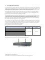
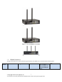
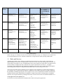
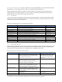
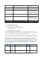
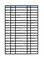
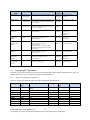
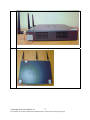
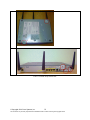
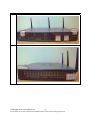
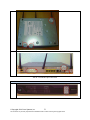
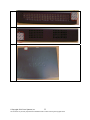
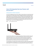
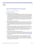
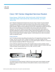
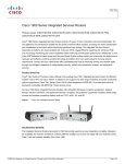
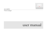
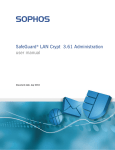
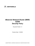
Cisco Integrated Services Router Security Policy Cisco 881W, 881GW, 1941W, 891W, C819HGW+7-A-A-K9, C819HGW-V-A-K9, C819HGWS-A-K9 and C819HWD-A-K9 FIPS 140-2 Non Proprietary Security Policy Level 2 Validation Version 0.8 April 2014 © Copyright 2014 Cisco Systems, Inc. This document may be freely reproduced and distributed whole and intact including this Copyright Notice. Table of Contents 1 INTRODUCTION .................................................................................................................. 3 1.1 1.2 1.3 1.4 1.5 PURPOSE ............................................................................................................................. 3 MODULE VALIDATION LEVEL ............................................................................................ 3 REFERENCES ....................................................................................................................... 3 TERMINOLOGY ................................................................................................................... 3 DOCUMENT ORGANIZATION ............................................................................................... 4 2 CISCO ISR WIRELESS ROUTERS ................................................................................... 5 2.1 2.2 2.3 2.4 2.5 2.6 2.7 2.8 MODULE INTERFACES ......................................................................................................... 7 ROLES AND SERVICES ......................................................................................................... 8 UNAUTHENTICATED SERVICES ......................................................................................... 10 CRYPTOGRAPHIC KEY MANAGEMENT .............................................................................. 10 CRYPTOGRAPHIC ALGORITHMS ........................................................................................ 13 SELF-TESTS ...................................................................................................................... 14 PHYSICAL SECURITY ........................................................................................................ 15 TAMPER LABELS............................................................................................................... 15 3 SECURE OPERATION ...................................................................................................... 27 3.1 3.2 3.3 3.4 3.5 INITIAL SETUP .................................................................................................................. 27 SYSTEM INITIALIZATION AND CONFIGURATION ................................................................ 27 IPSEC REQUIREMENTS AND CRYPTOGRAPHIC ALGORITHMS ............................................ 28 SSLV3.1/TLS REQUIREMENTS AND CRYPTOGRAPHIC ALGORITHMS ............................... 28 ACCESS............................................................................................................................. 28 © Copyright 2014 Cisco Systems, Inc. 2 This document may be freely reproduced and distributed whole and intact including this Copyright Notice. 1 1.1 Introduction Purpose This is the non-proprietary Cryptographic Module Security Policy for the Cisco 881W, 881GW, 1941W, 891W, C819HGW+7-A-A-K9, C819HGW-V-A-K9, C819HGW-S-A-K9 and C819HWD-A-K9 (Router Firmware Version: IOS 15.2(4)M5 and AP Firmware Version: 15.2.2-JB). This security policy describes how the modules meet the security requirements of FIPS 140-2 Level 2 and how to run the modules in a FIPS 140-2 mode of operation and may be freely distributed. FIPS 140-2 (Federal Information Processing Standards Publication 140-2 — Security Requirements for Cryptographic Modules) details the U.S. Government requirements for cryptographic modules. More information about the FIPS 140-2 standard and validation program is available on the NIST website at http://csrc.nist.gov/groups/STM/index.html. 1.2 Module Validation Level The following table lists the level of validation for each area in the FIPS PUB 140-2. No. 1 2 3 4 5 6 7 8 9 10 11 Area Title Cryptographic Module Specification Cryptographic Module Ports and Interfaces Roles, Services, and Authentication Finite State Model Physical Security Operational Environment Cryptographic Key management Electromagnetic Interface/Electromagnetic Compatibility Self-Tests Design Assurance Mitigation of Other Attacks Overall module validation level Level 2 2 3 2 2 N/A 2 2 2 3 N/A 2 Table 1 Module Validation Level 1.3 References This document deals only with the capabilities and operations of the Cisco 881W, 881GW, 1941W, 891W, C819HGW+7-A-A-K9, C819HGW-V-A-K9, C819HGW-S-A-K9 and C819HWD-A-K9 in the technical terms of a FIPS 140-2 cryptographic module security policy. More information is available on the routers from the following sources: For answers to technical or sales related questions please refer to the contacts listed on the Cisco Systems website at www.cisco.com. The NIST Validated Modules website (http://csrc.nist.gov/groups/STM/cmvp/validation.html) contains contact information for answers to technical or sales-related questions for the module. 1.4 Terminology In this document, these Cisco Integrated Services Router models identified above are referred to as Integrated Services Router, ISR or the systems. © Copyright 2014 Cisco Systems, Inc. 3 This document may be freely reproduced and distributed whole and intact including this Copyright Notice. 1.5 Document Organization The Security Policy document is part of the FIPS 140-2 Submission Package. In addition to this document, the Submission Package contains: Vendor Evidence document Finite State Machine Other supporting documentation as additional references This document provides an overview of the routers and explains their secure configuration and operation. This introduction section is followed by Section 2, which details the general features and functionality of the router. Section 3 specifically addresses the required configuration for the FIPS-mode of operation. With the exception of this Non-Proprietary Security Policy, the FIPS 140-2 Validation Submission Documentation is Cisco-proprietary and is releasable only under appropriate non-disclosure agreements. For access to these documents, please contact Cisco Systems. © Copyright 2014 Cisco Systems, Inc. 4 This document may be freely reproduced and distributed whole and intact including this Copyright Notice. 2 Cisco ISR Wireless Routers Cisco Integrated Service Routers (ISRs) are multifunctional networking devices delivering fast, reliable, data transfers with a high standard in security. These routers offer full network security, and other capabilities to fill networking needs for a small to medium size network. The Cisco Integrated Services Router (ISR) provides a scalable, secure, manageable remote access server that meets FIPS 140-2 Level 2 requirements. The following subsections describe the physical characteristics of the routers which is a multiple-chip standalone cryptographic module. The module is used to support 802.1X Authentication, SSH, TLS (VPN/Mgt/SIP), IPSec, GetVPN, Wireless (both Autonomous and CAPWAP), and SNMPv3. The cryptographic boundary of the module is defined as the device’s case along with any opacity shields associated with the system. All of the functionality discussed in this document is provided by components within this cryptographic boundary. The CF card that stored the IOS image is considered an internal memory module, because the IOS image stored in the card may not be modified or upgraded. The card itself must never be removed from the drive. Tamper evident seal will be placed over the card in the drive. Cisco C819HGW+7-A-A-K9, C819HGW-V-A-K9, C819HGW-S-A-K9 and C819HWD-A-K9 are all similar being that they are from the C819HGW family with minor changes to meet wireless carrier requirements. The C819HGW is similar to the C819GW. The difference between the two is the C819HGW is a hardened unit with its outer and inners designed to meet more stringent physical requirements. The tested platforms consist of the following components: Model Cisco 881W Integrated Services Router (ISR) Cisco 881GW Integrated Services Router (ISR) Cisco 1941W Integrated Services Router (ISR) Cisco 891W Integrated Services Router (ISR) Cisco C819HGW+7-A-A-K9 Integrated Services Router (ISR) Cisco C819HGW-V-A-K9 Integrated Services Router (ISR) Cisco C819HGW-S-A-K9 Integrated Services Router (ISR) Cisco C819HWD-A-K9 Integrated Services Router (ISR) Router Firmware Version AP Firmware Version IOS 15.2(4)M5 15.2.2-JB Table 2 Module Hardware Configurations The following pictures are representative each of the modules hardware model: Figure 1 - Cisco 881W ISR © Copyright 2014 Cisco Systems, Inc. 5 This document may be freely reproduced and distributed whole and intact including this Copyright Notice. Figure 2 - Cisco 881GW ISR Figure 3 - Cisco 1941W ISR Figure 4 - Cisco 891W ISR Figure 5 - Cisco C819HGW+7-A-A-K9 ISR © Copyright 2014 Cisco Systems, Inc. 6 This document may be freely reproduced and distributed whole and intact including this Copyright Notice. Figure 6 - Cisco C819HGW-V-A-K9 ISR Figure 7 - Cisco C819HGW-S-A-K9 ISR Figure 8 - Cisco C819HWD-A-K9 ISR 2.1 Module Interfaces The physical interfaces are separated into the logical interfaces from FIPS 140-2 as described in the following table: Logical Interface 881w 881gw © Copyright 2014 Cisco Systems, Inc. 1941w 7 C819HGW+7-A-AK9, C819HGW-V-AK9, C819HGW-S-AK9 and C819HWDA-K9 This document may be freely reproduced and distributed whole and intact including this Copyright Notice. 891w Logical Interface 881w 881gw 1941w C819HGW+7-A-AK9, C819HGW-V-AK9, C819HGW-S-AK9 and C819HWDA-K9 891w Input Fast Ethernet (FE) ports Antenna Ports Console/Auxiliary Port Fast Ethernet (FE) ports Gigabit Ethernet (GE) ports Antenna Ports Console/Auxiliary Port Gigabit Ethernet (GE) ports WAN interface slots EHWIC Radio Antenna Console Port Auxiliary Port USB Console Port Fast Ethernet (FE) ports Gigabit Ethernet (GE) ports WAN interface slots Console/Auxiliary Port Antenna Ports Gigabit Ethernet (GE) ports Fast Ethernet (FE) ports Antenna Ports Console Port Auxiliary Port Output Fast Ethernet (FE) ports Antenna Ports Console/Auxiliary Port Fast Ethernet (FE) ports Gigabit Ethernet (GE) ports 10/100 Mbps FE WAN port Antenna Ports Console/Auxiliary Port Gigabit Ethernet (GE) ports WAN interface slots EHWIC Antenna Ports Console Port Auxiliary Port USB Console Port Fast Ethernet (FE) ports Gigabit Ethernet (GE) ports WAN interface slots Console/Auxiliary Port Antenna Ports Gigabit Ethernet (GE) ports Fast Ethernet (FE) ports Antenna Ports Console Port Auxiliary Port Control Fast Ethernet (FE) ports Antenna Ports Console/Auxiliary Port Reset Button Fast Ethernet (FE) ports Gigabit Ethernet (GE) ports Antenna Ports Console/Auxiliary Port Gigabit Ethernet (GE) ports WAN interface slots EHWIC Antenna Ports Console Port Auxiliary Port USB Console Port Reset Button 10/100/1000 Gigabit Ethernet port WAN interface slots Console/Auxiliary Port Reset Button Antenna Ports Gigabit Ethernet (GE) ports Fast Ethernet (FE) ports Antenna Ports Console Port Auxiliary Port Reset Button Status Fast Ethernet (FE) ports Antenna Ports Console/Auxiliary Port Ethernet LED Ethernet Jack LEDs Top Panel Status LED Top Panel Radio LED Fast Ethernet (FE) ports Gigabit Ethernet (GE) ports Antenna Ports Console/Auxiliary Port Ethernet LED Ethernet Jack LEDs Top Panel Status LED Top Panel Radio LED Gigabit Ethernet (GE) ports WAN interface slots EHWIC Antenna Ports Console Port Auxiliary Port USB Console Port Top Panel Ethernet LED Ethernet Jack LEDs Top Panel Status LED Fast Ethernet (FE) ports Gigabit Ethernet (GE) ports WAN interface slots Console/Auxiliary Port LED Antenna Ports Gigabit Ethernet (GE) ports Fast Ethernet (FE) ports Antenna Ports ) Console Port Auxiliary Port LED Power 5v DC power supply 5v DC power supply 110v ~240v AC power supply 5v DC power supply 5v DC power supply POE POE POE Table 3 Module Interfaces NOTE: One type “A” USB port on each of Cisco 881W and 881GW, two type “A” USB ports on Cisco 891W and two Compact Flash slots on Cisco 1941W are disabled by covering with TELs while operating in FIPS-mode. 2.2 Roles and Services Authentication is identity-based. Each user is authenticated upon initial access to the module. The module also supports RADIUS or TACACS+ for authentication. There are two roles in the router that operators can assume: the Crypto Officer role and the User role. The administrator of the router assumes the Crypto Officer role and associated services in order to configure the router, while the Users exercise only the basic User services. A complete description of all the management and configuration capabilities of the router can be found in the Performing Basic System Management manual or Configuration Guide Manual and in the online help for the routers. All CO/User passwords must be 8 characters up to 25 characters with a minimum of one letter and one number. If six (6) integers, one (1) special character and one (1) alphabet are used without repetition for an eight (8) digit PIN, the probability of randomly guessing the correct sequence is one (1) in 251,596,800 (this calculation is based on the assumption that the typical standard American QWERTY computer keyboard has 10 Integer digits, 52 alphabetic characters, and 32 special characters providing 94 characters to choose from in total. The calculation should be 10 x © Copyright 2014 Cisco Systems, Inc. 8 This document may be freely reproduced and distributed whole and intact including this Copyright Notice. 9 x 8 x 7 x 6 x 5 x 32 x 52 = 251, 596, 800 ). Therefore, the associated probability of a successful random attempt is approximately 1 in 251,596,800, which is less than 1 in 1,000,000 required by FIPS 140-2. When using RSA based authentication, RSA key pair has modulus size of 2048 bit, thus providing 112 bits of strength. Therefore, an attacker would have a 1 in 2^112 chance of randomly obtaining the key, which is much stronger than the one in a million chance required by FIPS 140-2. 2.2.1 User Services Users enter the system by accessing the console port with a terminal program or via IPSec protected telnet or SSH session to a LAN port. The IOS prompts the User for username and password. If the password is correct, the User is allowed entry to the IOS executive program. The services available to the User role consist of the following: Services and Access Description Keys and CSPs Status Functions (r) Network Functions (r,w) View state of interfaces and protocols, version of IOS currently running. Connect to other network devices through outgoing telnet, PPP, etc. and initiate diagnostic network services (i.e., ping, mtrace). Adjust the terminal session (e.g., lock the terminal, adjust flow control). Display directory of files kept in flash memory. Execute the FIPS 140 start-up tests on demand Negotiation and encrypted data transport via SSL VPN (TLSv1.0) User password User password User password User password N/A User password Negotiation and encrypted data transport via IPSec VPN Negotiation and encrypted data transport via GetVPN Negotiation and encrypted data transport via SSH Negotiation and encrypted data transport via HTTPS User password User password User password User password Negotiation and encrypted data transport via SNMPv3 Negotiation and encrypted data transport via 802.11i User password User password Terminal Functions (r) Directory Services (r) Self-Tests (r) SSL VPN (TLSv1.0) (r, w, d) IPsec VPN (r, w, d) GetVPN (GDOI) (r, w, d) SSH Functions(r, w, d) HTTPS Functions (TLS) (r, w, d) SNMPv3 Functions(r, w, d) Wireless functions (r, w, d) Table 4 - User Services (r = read w = write d = delete) 2.2.2 Crypto Officer Services During initial configuration of the router, the Crypto Officer password (the “enable” password) is defined. A Crypto Officer can assign permission to access the Crypto Officer role to additional accounts, thereby creating additional Crypto Officers. The Crypto Officer role is responsible for the configuration of the router. The Crypto Officer services consist of the following: Services and Access Description Keys and CSPs Configure the router (r,w) Define network interfaces and settings, create command aliases, set the protocols the router will support, enable interfaces and network services, set system date and time, and load authentication information. Define Rules and Filters (r,w,d) Create packet Filters that are applied to User data streams on each interface. Each Filter consists of a set of Rules, which define a set of packets to permit or deny based on characteristics such as protocol ID, addresses, ports, TCP connection establishment, or packet direction. View the router configuration, routing tables, active sessions, use gets to view SNMP MIB statistics, health, temperature, memory status, voltage, packet statistics, review accounting logs, and view physical interface status. Log off users, shutdown or reload the router, erase the flash memory, manually back up router configurations, view complete configurations, manager user rights, and restore router configurations. Non security-related monitoring by the CO using SNMPv3. Set up the configuration tables for IP tunneling. Set ISAKMP pre-shared keys, IKE Authentication key, IKE Encryption Key, IPSec authentication keys, IPSec traffic keys, User passwords, Enable password, Enable secret, password View Status Functions (r) Manage the router (r,w,d) SNMPv3 (r) Configure Encryption/Bypass © Copyright 2014 Cisco Systems, Inc. 9 password password SnmpEngineID, SNMP v3 password, SNMP session key ISAKMP pre-shared keys, IKE This document may be freely reproduced and distributed whole and intact including this Copyright Notice. (r,w,d) SSL VPN (TLSv1.0) (r,w,d) SSH v2 (r, w, d) IPsec VPN (r, w, d) preshared keys and algorithms to be used for each IP range or allow plaintext packets to be set from specified IP address. Configure SSL VPN parameters, provide entry and output of CSPs. Configure SSH v2 parameter, provide entry and output of CSPs. Configure IPsec VPN parameters, provide entry and output of CSPs. GetVPN (GDOI) (r, w, d) Configure GetVPN parameters, provide entry and output of CSPs. Wireless Functions (r, w, d) Configure wireless parameters, provide entry and output of CSPs. Self-Tests (r) User services (r,w,d) Zeroization (d) Execute the FIPS 140 start-up tests on demand The Crypto Officer has access to all User services. Zeroize cryptographic keys Authentication key, IKE Encryption Key, IPSec authentication keys, IPSec traffic keys, Enable secret, TLS pre-master secret, TLS Traffic Keys SSH Traffic Keys skeyid, skeyid_d, IKE session encryption key, IKE session authentication key, ISAKMP pre-shared, IKE authentication private Key, IKE authentication public key, IPSec encryption key, IPSec authentication key GDOI key encryption key (KEK), GDOI traffic encryption key (TEK), GDOI TEK integrity key 802.11i Pre-shared Key (PSK), 802.11i Pairwise Master Key (PMK), 802.11i Pairwise Transient Key (PTK), 802.11i Temporal Key (TK), 802.11i Group Master Key (GMK), 802.11i Group Temporal Key (GTK) N/A Password All CSPs Table 5 - Crypto Officer Services (r = read w = write d = delete) 2.3 Unauthenticated Services The services available to unauthenticated users are: Viewing the status output from the module’s LEDs Powering the module on and off using the power switch Sending packets in bypass 2.4 Cryptographic Key Management The router securely administers both cryptographic keys and other critical security parameters such as passwords. All keys are protected by the Crypto Officer role login password-protection, and these keys can be zeroized by the Crypto Officer. Zeroization consists of overwriting the memory that stored the key. The router is in the approved mode of operation only when FIPS 140-2 approved algorithms are used (except DH and RSA key transport which are allowed in the approved mode for key establishment despite being non-approved). All pre-shared keys are associated with the CO role that created the keys, and the CO role is protected by a password. Therefore, the CO password is associated with all the pre-shared keys. The Crypto Officer needs to be authenticated to store keys. All Diffie-Hellman (DH) keys agreed upon for individual tunnels are directly associated with that specific tunnel only via the Internet Key Exchange (IKE)/Group Domain of Interpretation (GDOI). RSA Public keys are entered into the modules using digital certificates which contain relevant data such as the name of the public key's owner, which associates the key with the correct entity. All other keys are associated with the user/role that entered them. Key/CSP Name RNG Seed RNG Seed Key Algorithm ANSI X9.31 Appendix A.2.4 Using the 2-Key Triple-DES Algorithm (128bits) ANSI X9.31 Appendix A.2.4 Using the 2-Key Description Storage Location Zeroization Method This is the seed for X9.31 RNG. Used by the AP portion of the module SDRAM (plaintext) power cycle the device This is the seed key for X9.31 RNG. Used by the AP portion of the module SDRAM (plaintext) power cycle the device © Copyright 2014 Cisco Systems, Inc. 10 This document may be freely reproduced and distributed whole and intact including this Copyright Notice. Key/CSP Name Algorithm Description Storage Location Zeroization Method Triple-DES Algorithm (64bits) DRBG entropy input SP 800-90 CTR_DRBG (256-bits) This is the entropy for SP 800-90a RNG. SDRAM (plaintext) power cycle the device DRBG seed SP 800-90 CTR_DRBG (384-bits) This is the seed for SP 800-90a RNG. SDRAM (plaintext) power cycle the device DRBG V SP 800-90 CTR_DRBG (256-bits) Internal V value used as part of SP 800-90a CTR_DRBG SDRAM (plaintext) power cycle the device DRBG key SP 800-90 CTR_DRBG (256-bits) Internal Key value used as part of SP 800-90a CTR_DRBG SDRAM (plaintext) power cycle the device Diffie-Hellman private key DH (224 – 379 bits) The private key used in Diffie-Hellman (DH) exchange. SDRAM (plaintext) Automatically after shared secret generated. Diffie-Hellman public key DH (2048 – 4096 bits) The p used in Diffie-Hellman (DH) exchange. SDRAM (plaintext) Automatically after shared secret generated. Diffie-Hellman shared secret DH (2048 – 4096 bits) The shared key used in Diffie-Hellman (DH) exchange. Created per the Diffie-Hellman protocol. SDRAM (plaintext) Zeroized upon deletion. EC DiffieHellman private key ECDH ( P256/P-384) The private key used in Elliptic Curve DiffieHellman (ECDH) exchange. SDRAM (plaintext) Automatically after shared secret generated. EC DiffieHellman public key ECDH (P-256/P384) The p used in Elliptic Curve Diffie-Hellman (ECDH) exchange. SDRAM (plaintext) Automatically after shared secret generated. EC DiffieHellman shared secret ECDH (P-256/P384) SDRAM (plaintext) Zeroized upon deletion. skeyid HMAC-SHA-1 (160-bits) The shared key used in Elliptic Curve DiffieHellman (ECDH) exchange. Created per the Elliptic Curve Diffie-Hellman (ECDH) protocol. Value derived from the shared secret within IKE exchange. Zeroized when IKE session is terminated. SDRAM (plaintext) Automatically after IKE session terminated. skeyid_d HMAC-SHA-1 (160-bits) The IKE key derivation key for non ISAKMP security associations. SDRAM (plaintext) Automatically after IKE session terminated. IKE session encryption key The IKE session encrypt key. SDRAM (plaintext) Automatically after IKE session terminated. IKE session authentication key Triple-DES (168-bits/AES (128/196/256bits) HMAC-SHA-1 (160-bits) The IKE session authentication key. SDRAM (plaintext) Automatically after IKE session terminated. ISAKMP preshared Shared secret ( 8 – 25 characters) The key used to generate IKE skeyid during preshared-key authentication. NVRAM (plaintext) “# no crypto isakmp key” IKE authentication private Key RSA (2048/3072 bits); ECDSA (P-256/P-384) RSA private key for IKE authentication. NVRAM (plaintext) “# crypto key zeroize rsa" IKE authentication public key RSA (2048/3072 bits); ECDSA (P-256/P-384) RSA public key for IKE authentication. SDRAM (plaintext) “# crypto key zeroize rsa" © Copyright 2014 Cisco Systems, Inc. 11 This document may be freely reproduced and distributed whole and intact including this Copyright Notice. Key/CSP Name IPSec encryption key Algorithm Description Storage Location Zeroization Method The IPSec encryption key. Zeroized when IPSec session is terminated. SDRAM (plaintext) “# Clear Crypto IPSec SA” IPSec authentication key Triple-DES (168-bits/AES (128/196/256bits) HMAC-SHA-1 (160-bits) The IPSec authentication key. The zeroization is the same as above. SDRAM (plaintext) “# Clear Crypto IPSec SA” SSH RSA private key RSA (2048/3072 bits) The SSH v2 private key for the module. NVRAM (plaintext) “# crypto key zeroize rsa" SSH RSA public key RSA (2048/3072 bits) The SSH v2 public key for the module. SDRAM (plaintext) “# crypto key zeroize rsa" SSH session keys This is the SSH v2 session key. It is zeroized when the SSH v2 session is terminated. SDRAM (plaintext) Automatically when SSH v2 session terminated TLS server private key Triple-DES (168-bits/AES (128/196/256bits) RSA (2048/3072 bits) Private key used for SSLv3.1/TLS. NVRAM (plaintext) “# crypto key zeroize rsa" TLS server public key RSA (2048/3072 bits) Public key used for SSLv3.1/TLS. NVRAM (plaintext) “# crypto key zeroize rsa" TLS pre-master secret Shared Secret (384-bits) Shared Secret created using asymmetric cryptography from which new TLS session keys can be created SDRAM (plaintext) Automatically when TLS session is terminated TLS session encryption key Triple-DES (168-bits/AES (128/196/256bits) HMAC-SHA-1 (160-bits) Key used to encrypt TLS session data SDRAM (plaintext) Automatically when TLS session is terminated HMAC-SHA-1 used for TLS data integrity protection SDRAM (plaintext) Automatically when TLS session is terminated GDOI key encryption key (KEK) AES (128, 192 and 256 bits) This key is created using the “GROUPKEYPULL” registration protocol with GDOI. It is used protect GDOI rekeying data.” SDRAM (plaintext) Automatically when session terminated. GDOI traffic encryption key (TEK) Triple-DES (168-bits/AES (128/196/256bits) SDRAM (plaintext) Automatically when session terminated. GDOI TEK integrity key HMAC-SHA-1 (160-bits) SDRAM (plaintext) Automatically when session terminated. snmpEngineID Shared Secret (32-bits) This key is created using the “GROUPKEYPULL” registration protocol and updated using the “GROUPKEY-PUSH” registration protocol with GDOI. It is used to encrypt data traffic between Get VPN peers This key is created using the “GROUPKEYPULL” registration protocol and updated using the “GROUPKEY-PUSH” registration protocol with GDOI. It is used to ensure data traffic integrity between Get VPN peers. A unique string used to identify the SNMP engine. NVRAM (plaintext) Overwrite with new engine ID SNMP v3 password Shared Secret ( 8 – 25 characters) The password use to setup SNMP v3 connection. NVRAM (plaintext) Overwrite with new password SNMP session key AES (128 bits) Encryption key used to protect SNMP traffic. SDRAM (plaintext) Automatically when session terminated. User password Shared Secret ( 8 – 25 characters) The password used to authenticate the User role. NVRAM (plaintext) Overwrite with new password TLS session integrity key © Copyright 2014 Cisco Systems, Inc. 12 This document may be freely reproduced and distributed whole and intact including this Copyright Notice. Key/CSP Name Algorithm Description Storage Location Zeroization Method Enable secret Shared Secret ( 8 – 25 characters) The password used to authenticate the CO role. NVRAM (plaintext) Overwrite with new password RADIUS secret Shared Secret ( 8 – 25 characters) The RADIUS shared secret. This shared secret is zeroized by executing the “no radius-server key” command. NVRAM (plaintext) “# no radius-server key” TACACS+ secret Shared Secret ( 8 – 25 characters) The TACACS+ shared secret. This shared secret is zeroized by executing the “no tacacsserver key” command. NVRAM (plaintext) “# no tacacs-server key” 802.11i Pre-shared Key (PSK) Shared Secret The PSK is used to derive the PMK for 802.11i communications. DRAM (plaintext) 802.11i Pairwise Master Key (PMK) HMAC-SHA-1 256-bit The PMK is Used to derive the Pairwise Transient Key (PTK) for 802.11i communications. DRAM (plaintext) Using either the “no wpa-psk” or “no dot11 ssid” command Automatically when the router is powercycled. 802.11i Pairwise Transient Key (PTK) AES-CCM DRAM (plaintext) Automatically when session terminated. 802.11i Temporal Key (TK) AES-CCM The PTK, also known as the CCMP key, is the 802.11i session key for unicast communications. This key also used to encrypt and sign management frames between AP and the wireless client. The TK, also known as the CCMP key, is the 802.11i session key for unicast communications. DRAM (plaintext) Automatically when session terminated. 802.11i Group Master Key (GMK) HMAC-SHA-1 The GMK is Used to derive the Group Temporal Key (GTK) for 802.11i communications. DRAM (plaintext) Automatically when the router is powercycled. 802.11i Group Temporal Key (GTK) AES-CCM The GTK is the 802.11i session key for broadcast communications. DRAM (plaintext) Automatically when session terminated. Table 6 – CSP/PSP Table 2.5 Cryptographic Algorithms The router is in the approved mode of operation only when FIPS 140-2 approved/allowed algorithms are used. The module implements a variety of approved and non-approved algorithms. 2.5.1 Approved Cryptographic Algorithms The routers support the following FIPS 140-2 approved algorithm implementations: AES Router IOS #2620 Triple-DES SHS HMAC RSA ECDSA DRBG CVL RNG #1566 #2182 #1606 #1338 #450 #401 #231 N/A Router HW Accelerator AP IOS #2611 Wireless Radio Mac #1791 #962, #1115, #1535 and #1648 #757, #758 and #812 #933, #934 and #1038 #537, #538 and #627 N/A N/A N/A N/A N/A N/A N/A #2194 #1618 N/A N/A N/A N/A #1236 N/A N/A N/A N/A N/A N/A N/A N/A N/A #2208 N/A #1347 N/A N/A N/A N/A Table 7 – Algorithm Certificates © Copyright 2014 Cisco Systems, Inc. 13 This document may be freely reproduced and distributed whole and intact including this Copyright Notice. Image Signing Note: RSA (Cert. #1338; non-compliant with the functions from the CAVP Historical RSA List). o FIPS186-4: 186-4KEY(gen): PGM(ProvPrimeCondition) (1024 SHA( 256 )) ALG[RSASSA-PKCS1_V1_5] SIG(gen) (1024 SHA( 1 , 256 )) (2048 SHA(1)) (3072 SHA(1)) The modules support the following key establishment/derivation schemes: Diffie-Hellman (key establishment methodology provides between 112 and 150 bits of encryption strength; non-compliant less than 112 bits of encryption strength) EC Diffie-Hellman (key establishment methodology provides between 128 and 192 bits of encryption strength) 2.5.2 RSA (key wrapping; key establishment methodology provides between 112 and 128 bits of encryption strength; non-compliant less than 112 bits of encryption strength) GDOI (key wrapping; key establishment methodology provides between 112 and 150 bits of encryption strength) Non-FIPS Approved Algorithms Integrated Services Routers (ISRs) cryptographic module implements the following non-Approved algorithms: MD5 DES HMAC-MD5 RC4 Self-Tests 2.6 In order to prevent any secure data from being released, it is important to test the cryptographic components of a security module to insure all components are functioning correctly. The router includes an array of self-tests that are run during startup and periodically during operations. In the error state, all secure data transmission is halted and the router outputs status information indicating the failure. 2.6.1 Router Power-On Self-Tests (POSTs) IOS Algorithm Self-Tests o AES (encrypt/decrypt) Known Answer Tests o AES GCM Known Answer Test o DRBG Known Answer Test o ECDSA Sign/Verify o HMAC (SHA-1) Known Answer Test o RSA Known Answer Test o SHS (SHA-1/256/512) Known Answer Tests o Triple-DES (encrypt/decrypt) Known Answer Tests Hardware Accelerator Self-Tests o AES (encrypt/decrypt) Known Answer Tests o Triple-DES (encrypt/decrypt) Known Answer Tests o HMAC (SHA-1) Known Answer Test Firmware Integrity Test o RSA PKCS#1 v1.5 (2048 bits) signature verification with SHA-512 © Copyright 2014 Cisco Systems, Inc. 14 This document may be freely reproduced and distributed whole and intact including this Copyright Notice. 2.6.2 AP Power-On Self-Tests (POSTs) IOS Algorithm Known Answer Testes: o AES (encrypt/decrypt) Known Answer Tests o AES-CCM Known Answer Test o RNG Known Answer Test o HMAC (SHA-1) Known Answer Test AP Radio MAC Known Answer Tests: o AES-CCM Known Answer Test Firmware Integrity Test o 32-bits CRC 2.6.3 2.6.4 2.7 Router Conditional Tests Conditional Bypass test Continuous random number generation test for approved and non-approved RNGs Pairwise consistency test for ECDSA Pairwise consistency test for RSA AP Conditional Tests Continuous random number generation test for approved and non-approved RNGs Physical Security The router is entirely encased by a metal, opaque case requiring tamper evidence labels and opacity shields. The exact physical make-up differs over models but once the routers have been configured to meet FIPS 140-2 Level 2 requirements, the routers cannot be accessed without signs of tampering. Any attempt to open the router will damage the tamper evidence seals or the material of the module cover. All Critical Security Parameters are stored and protected within each module's tamper evident enclosure. The Crypto Officer is responsible for properly placing all tamper evident labels. The security labels recommended for FIPS 1402 compliance are provided in the FIPS Kit (Part Number CISCO-FIPS-KIT=), Revision -B0. The FIPS kit includes 15 of the seals, as well as a document detailing the number of seals required per platform and placement information. Please be aware that the extra tamper evident labels/seals shall be securely stored by the Crypto Officer. These security labels are very fragile and cannot be removed without clear signs of damage to the labels. Tamper evidence seals can be inspected for signs of tampering, which include the following: curled corners, bubbling, crinkling, rips, tears, and slices. The word “OPEN” will appear if the label was peeled back. Model # labels Tamper Evident Labels 881W 881GW 891W 1941W C819HGW+7-A-A-K9, C819HGW-V-A-K9, C819HGW-S-A-K9, C819HWD-A-K9 7 9 6 8 4 FIPS Kit (CISCO-FIPS-KIT=), Revision -B0 FIPS Kit (CISCO-FIPS-KIT=), Revision -B0 FIPS Kit (CISCO-FIPS-KIT=), Revision -B0 FIPS Kit (CISCO-FIPS-KIT=), Revision -B0 FIPS Kit (CISCO-FIPS-KIT=), Revision -B0 Table 8 – Tamper Evident labels 2.8 Tamper Labels To install the Tamper Evident Labels, please follow these steps © Copyright 2014 Cisco Systems, Inc. 15 This document may be freely reproduced and distributed whole and intact including this Copyright Notice. 1 2 3 4 Clean the cover of any grease, dirt, or oil before applying the tamper evidence labels. Alcohol-based cleaning pads are recommended for this purpose. The temperature of the router should be above 10C. The tamper evidence label should be placed over the CF card in the slot so that any attempt to remove the card will show sign of tampering. The tamper evidence label should be placed as indicated in the pictures below associated with the actual unit. The labels completely cure within five minutes. NOTE: Any unused TELs must be securely stored, accounted for, and maintained by the CO in a protected location. NOTE: These security labels are very fragile and cannot be removed without clear signs of damage to the labels. The Crypto-Officer should inspect the seals for evidence of tamper as determined by their deployment policies (every 30 days is recommended). If the seals show evidence of tamper, the Crypto-Officer should assume that the modules have been compromised and contact Cisco accordingly. The following figures identify the placement of each TEL for each hardware model: Cisco 881W Front Right © Copyright 2014 Cisco Systems, Inc. 16 This document may be freely reproduced and distributed whole and intact including this Copyright Notice. Left Top © Copyright 2014 Cisco Systems, Inc. 17 This document may be freely reproduced and distributed whole and intact including this Copyright Notice. Bottom Back Table 9 – Cisco 881W Tamper Evident labels © Copyright 2014 Cisco Systems, Inc. 18 This document may be freely reproduced and distributed whole and intact including this Copyright Notice. Cisco 881GW Front Right © Copyright 2014 Cisco Systems, Inc. 19 This document may be freely reproduced and distributed whole and intact including this Copyright Notice. Left Top © Copyright 2014 Cisco Systems, Inc. 20 This document may be freely reproduced and distributed whole and intact including this Copyright Notice. Bottom Back Table 10 – Cisco 881GW Tamper Evident labels Cisco 891W Front © Copyright 2014 Cisco Systems, Inc. 21 This document may be freely reproduced and distributed whole and intact including this Copyright Notice. Right Left Top © Copyright 2014 Cisco Systems, Inc. 22 This document may be freely reproduced and distributed whole and intact including this Copyright Notice. Bottom Back Table 11 – Cisco 891W Tamper Evident labels Cisco 1941W Front © Copyright 2014 Cisco Systems, Inc. 23 This document may be freely reproduced and distributed whole and intact including this Copyright Notice. Right Left Top Bottom © Copyright 2014 Cisco Systems, Inc. 24 This document may be freely reproduced and distributed whole and intact including this Copyright Notice. Back Table 12 – Cisco 1941W Tamper Evident labels Cisco C819HGW+7-A-A-K9, C819HGW-V-A-K9, C819HGW-S-A-K9 and C819HWD-A-K9 Right (all) Left (all) Top (all) © Copyright 2014 Cisco Systems, Inc. 25 This document may be freely reproduced and distributed whole and intact including this Copyright Notice. Bottom (C819HGW-V-AK9, C819HGW-S-A-K9, C819HWD-A-K9) Bottom (C819HGW+7-A-A-K9) Back (C819HWD-A-K9, C819HGW-V-A-K9, C819HGW+7-A-A-K9) © Copyright 2014 Cisco Systems, Inc. 26 This document may be freely reproduced and distributed whole and intact including this Copyright Notice. Front (C819HWD-A-K9) Front (C819HGW-S-A-K9, C819HGW-V-A-K9) Front (C819HGW+7-A-A-K9) Table 13 – Cisco C819HGW+7-A-A-K9, C819HGW-V-A-K9, C819HGW-S-A-K9 and C819HWD-A-K9 Tamper Evident labels 3 Secure Operation The Cisco 881W, 881GW, 1941W, 891W, C819HGW+7-A-A-K9, C819HGW-V-A-K9, C819HGW-S-A-K9 and C819HWD-A-K9 Integrated Services Routers meet all the Level 2 requirements for FIPS 140-2. Follow the setting instructions provided below to place the module in FIPS-approved mode. Operating this router without maintaining the following settings will remove the module from the FIPS approved mode of operation. Initial Setup 3.1 1 2 The Crypto Officer must apply tamper evidence labels as described in Section 2.8 of this document. The Crypto Officer must disable IOS Password Recovery by executing the following commands: configure terminal no service password-recovery end show version NOTE: Once Password Recovery is disabled, administrative access to the module without the password will not be possible. System Initialization and Configuration 3.2 1 The Crypto Officer must perform the initial configuration. IOS 15.2(4)M5 (Router firmware version) and 15.2.2-JB (AP firmware version), Advanced Security build (advsecurity) are the only allowable images; no other image should be loaded. Once this image has been installed, no updates to software or firmware are permitted in FIPS mode of operations. © Copyright 2014 Cisco Systems, Inc. 27 This document may be freely reproduced and distributed whole and intact including this Copyright Notice. 2 The value of the boot field must be 0x0102. This setting disables break from the console to the ROM monitor and automatically boots the IOS image. From the “configure terminal” command line, the Crypto Officer enters the following syntax: config-register 0x0102 3 The Crypto Officer must create the “enable” password for the Crypto Officer role. The password must be at least 8 characters (all digits; all lower and upper case letters; and all special characters except ‘?’ are accepted) and is entered when the Crypto Officer first engages the “enable” command. The Crypto Officer enters the following syntax at the “#” prompt: enable secret [PASSWORD] 4 The Crypto Officer must always assign passwords (of at least 8 characters) to users. Identification and authentication on the console port is required for Users. From the “configure terminal” command line, the Crypto Officer enters the following syntax: line con 0 password [PASSWORD] login local 5 RADIUS and TACACS+ shared secret key sizes must be at least 8 characters long. IPSec Requirements and Cryptographic Algorithms 3.3 1 The only type of key management protocol that is allowed in FIPS mode is Internet Key Exchange (IKE), although manual creation of security associations is also permitted. 2 Although the IOS implementation of IKE allows a number of algorithms, only the following algorithms are allowed in a FIPS 140-2 configuration: 3 ah-sha-hmac esp-sha-hmac esp-Triple-DES esp-aes The following algorithms are not FIPS approved and should not be used during FIPS-approved mode: DES MD-5 for signing MD-5 HMAC SSLV3.1/TLS Requirements and Cryptographic Algorithms 3.4 When negotiating TLS cipher suites, only FIPS approved algorithms must be specified. All other versions of SSL except version 3.1 must not be used in FIPS mode of operation. The following algorithms are not FIPS approved and should not be used in the FIPS-approved mode: MD5 RC4 DES Access 3.5 1 Telnet access to the module is only allowed via a secure IPSec tunnel between the remote system and the module. The Crypto officer must configure the module so that any remote connections via telnet are secured through IPSec, using FIPS-approved algorithms. Note that all users must still authenticate after remote access is granted. © Copyright 2014 Cisco Systems, Inc. 28 This document may be freely reproduced and distributed whole and intact including this Copyright Notice. 2 SSH access to the module is only allowed if SSH is configured to use a FIPS-approved algorithm. The Crypto officer must configure the module so that SSH uses only FIPS-approved algorithms. Note that all users must still authenticate after remote access is granted. 3 SNMP access is only allowed via when SNMPv3 is configured with AES encryption. © Copyright 2014 Cisco Systems, Inc. 29 This document may be freely reproduced and distributed whole and intact including this Copyright Notice.