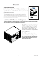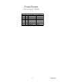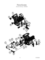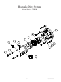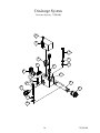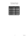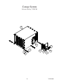
1
Service and
Maintenance
User Manual
Auto Crane
AC40 Piston
Hydraulic Air Compressor
This manual must be read carefully before using your Auto Crane Air Compressor.
Store in a safe and convenient location for future reference.
For technical support:
Phone: (918) 836-0463
Fax: (918) 834-5979
http://www.autocrane.com
755501900
8/19/2013 CRH
2
755501900
Contents
Revision List....................................................................................................5
Welcome.......................................................................................................6
Safety Information............................................................................................7
Warnings, safety rules, and hazards...........................................................7
Specifications..............................................................................................10
Description of Components...........................................................................11
Installation & Operation...................................................................................12
Installation........................................................................................12
Before Starting..................................................................................14
Initial Start-up & Test.......................................................................16
Maintenance........................................................................................17
Overview.............................................................................................17
Recommended Spare Parts List............................................................17
Maintenance Schedule........................................................................18
Lubrication Recommendation................................................................19
Compressor Oil ........................................................................................20
Air Intake Filter..................................................................................20
Hydraulic Oil Cooler........................................................................21
Troubleshooting......................................................................................22
General Tips............................................................................................22
Contacting Auto Crane..............................................................................23
Where To Find Specific Machine Information.......................................23
3
755501900
Drawings.....................................................................................................25
Frame System...............................................................................26
Piston System.......................................................................................28
Piston Assembly.....................................................................................30
Cooler System.................................................................................32
Hydraulic Drive System.....................................................................34
Discharge System...............................................................................36
Canopy System...............................................................................38
Decal System.................................................................................40
Wiring Diagram...............................................................................42
Warranty.....................................................................................................43
4
755501900
Revision List
D ATE
LOCATION D ESCPR IPTION OF CHAN GE
5
IN ITIALS
755501900
Welcome
General Information
Thank you for choosing the Auto Crane AC40 Hydraulic Air Compressor.
Before operating this compressor, read over this manual and become well
acquainted with your new machine. Doing this will increase your safety and
maximize the life of the machine.
While this manual is written to be as accurate as possible, Auto Crane
strives to continually improve the efficiency and performance of its machines. As a result, sometimes there may be slight differences between a
given version of the manual and the machine.
Service and
Maintenance
User Manual
Auto Crane
AC40 Piston
Hydraulic Air Compressor
This manual must be read carefully before using your Auto Crane Air Compressor.
Store in a safe and convenient location for future reference.
For technical support:
Phone: (918) 836-0463
Fax: (918) 834-5979
http://www.autocrane.com
308555
7/31/2013 ARB
Auto Crane AC40 Hydraulic Air Compressor
The Auto Crane AC40 is a compact, strategically designed system. It integrates all major components on a
single frame, which is enclosed in a tough, weather-resistant canopy.
The AC40 Piston design provides output of up to
40 CFM (cubic feet of air per minute) at up to a
maximum of 150 PSI (pounds per square inch).
High output at relatively low GPM (gallons per
minute) translates into the most efficient, quiet,
and reliable system in its class, designed to handle
virtually any application.
The AC40 Piston also has enhanced safety
features offering applications designed to protect
your most valuable resource - your operating
crew. To prevent overheating, a high temperature
switch will shut down the machine in the event of
high discharge temperatures.
6
755501900
Safety
IMPORTANT READ BEFORE OPERATING EQUIPMENT
Remember, safety is basically common sense. While there are standard safety rules, each situation has its
own peculiarities that cannot always be covered by rules. Therefore with your experience and common
sense, you are in a position to ensure your and others safety. Lack of attention to safety can result in:
accidents, personal injury, reduction in efficiency and worst of all – Loss of Life. Watch for safety hazards
and correct them promptly.
Understanding the proper operation of this equipment is critical to its safe operation. The owner, lessor or
operator of this equipment is hereby notified and forewarned that any failure to observe the safety and
operating guidelines may result in injury and/or damage. Auto Crane expressly disclaims responsibility or
liability for any injury or damage caused by failure to observe these specified precautions or by failure to
exercise the ordinary caution and due care required while operating or handling this equipment, even though
not expressly specified.
In addition to following these safety guidelines, the operator should follow any company specific guidelines
and procedures. Consult your immediate supervisor for specific company safety guidelines and/or procedures.
The following safety symbols are used throughout the manual to draw attention to important information. If
the information is not carefully read and the instructions are not followed, severe injury, death, and/or
damage to property and equipment may occur.
Indicate[s] an imminently hazardous situation, which, if
not avoided, will result in death or serious injury.
Indicate[s] a potentially hazardous situation, which, if not
avoided, could result in death or serious injury.
Indicate[s] a potentially hazardous situation, which, if not
avoided, could result in minor or moderate injury.
Indicate[s] a potentially unsafe situation or practice,
which, if not avoided can result in property and/or
equipment damage only.
7
755501900
Safety
The following safety precautions are a general guide to safe operation of the equipment.
Read and understand the operations manual and all other safety
instructions before using this equipment. Failure to follow
operating instructions and/or failure to follow maintenance procedures and intervals could result in personal injury, death, and/or
damage to equipment and property.
Pressurized System. Do not attempt to remove any compressor
parts without first completely relieving entire system of pressure.
Do not attempt to service any part of the equipment while in
operation. Never attempt to repair or modify any pressure vessel
or device.
System contains hot oil. The compressor system must be shut off
prior to servicing. Open the service valve to ensure complete relief
of system air pressure and stored energy. Then permit system to
cool down prior to adding compressor oil or servicing the unit.
Do not use air from this compressor for breathing or food processing. Air from this compressor will cause severe injury if used for
breathing or food processing.
The compressor is designed to compress air only. Do not attempt
to compress other gases. Compression of other gases may create
a situation where an explosion or fire may occur.
Do not use flammable solvents for cleaning compressor parts as
this can cause the unit to ignite or explode during operation. Keep
combustibles out of and away from compressor inlet, and any
associated enclosures.
8
755501900
Safety
Never disable, override, or remove safeties, either temporarily or permanently.
Connect air hoses only in full compliance with OSHA Standard 29 CFR
1926:302 (b)(7). The required safety devices (velocity fuses) should be
tested in accordance with their manufacturer’s recommendations to verify that
they reduce pressure in case of hose failure and will not nuisance trip with the
hose and tool combinations in use. Failure to comply could result in personal
injury or death and/or damage to equipment and property.
Never leave the machine running unattended or leave a tool connected to an
air hose when not using. Relieve system of all stored air pressure after use.
Never adjust the pressure switch to a setting of greater than 150 PSI. Operating the compressor at greater than 150 PSI may result in personal injury and
property damage.
Mount the compressor in a stable location capable of supporting 180 lbs.
Slight vibration may occur during operation and the machine may move if not
securely mounted.
When using tools, maintain secure footing at all times. Do not overreach or
awkwardly use air tools.
Prior to moving vehicle to the next work site, drain the air tank. To prevent
the collection of water in the tank drain daily.
Use only Auto Crane approved replacement parts.
9
755501900
Specifications
POWER SOUR CE
HYDRAULIC MO TO R
OPER ATIN G SPEED
CYLIN D ER CON FIG.
V4 Piston
OIL CAPACITY
1 1/3 Q TS
D IM EN SION S
28 1/2"L x 17"H x 20 7/8"W
WEIGHT
180 LBS.
D ELIVERY @ 100 PSI
40 C F M
HYD R AULIC R ESERVOIR
R EQ. *
20 GALLO N MIN IMUM
COOLIN G
AIR
N OR M AL GPM @ 1650 R PM
12.18 GPM
FAN D IAM ETER
14 1/8"
N OR M AL OPER ATIN G PSI
1450 PSI
M AXIM UM PSI
2 10 0 P S I
1650 RPM MAX.
* Hydraulic reservoir requirement for compressor only. Additional capacity will be needed for other hydraulic
equipment.
SPECIFICATIONS SUBJECT TO CHANGE WITHOUT PRIOR NOTICE
17
20 7/8
28 1/2
31 3/8
– AC40 system is to run intermittently.
– When the AC40 is installed with other hydraulic drive equipment it will require a dedicated flow line.
– If other hydraulics are required, the hydraulic reservoir size should be at least 20 GAL for the AC40 plus all
the other manufacturer’s requirements.
– Mounting surface must be capable of 180 lbs. load spread over the four mounting holes.
– Cooling air intake must not see air temperatures above ambient.
– Cooling air discharge must have 10” clearance from any obstructions.
– Ambient running conditions: -20° to 100° F.
– 20° maximum operating slope.
10
755501900
Description of Components
Compressor Assembly - The Auto Crane AC40 hydraulic drive piston compressor assembly is a positive
displacement, intermittent-flow, reciprocating unit. The piston compressor consists of a crankshaft, oil filter,
oil pump, four connecting rods, pistons, cylinders, and valve assemblies. As the crankshaft rotates, the
pistons move up and down. As they move down, a vacuum is created above the piston which allows the
reed valve to open and fill the area above the piston with air. When the pistons move back up, this air is
discharged from the compressor. Oil lubricates the bearings and cylinder walls as the crankshaft rotates,
ensuring that the system stays cool.
Hydraulic Oil Cooling Systems - The compressor cooling system consists of a hydraulic cooler mounted
on the compressor frame. Cool air is drawn through the vented end panel and flows over the compressor
surface and through the hydraulic cooler, exiting out the front vented panel . Allow for adequate clearance
(10”) for the air to exit. Also, the package location should not be subjected to air temperatures above
ambient.
Fluid Level Sight Glass - This sight glass indicates the fluid level in the crank case. Proper level should be
in the middle of the sight glass. Check this level when the compressor is disengaged and the vehicle is
parked on level ground. Fluid level should be checked prior to each use.
Electrical System - The Auto Crane compressor’s standard electrical system consists of:
-Hydraulic oil cooler fan assembly and relay.
-12VDC N.O. hydraulic solenoid.
-Switch relay for customer equipment interface during compressor operation.
Most air tools operating pressure range is between 90 and 125 psi.
Operating above the tools’ recommended pressures will decrease the life
of the tool. Higher operating pressure can also over torque nuts and bolts
fatiguing the fastener and mating parts. Strictly adhere to tool operating
pressures and torque standards set forth by the tool manufacturer and the
specifications of the equipment that work is being performed on.
Pressure Switch - The pressure switch is a N.C. electrical switch set to open at 150 PSI and set to close
at 115 PSI. The pressure switch controls the N.O. hydraulic solenoid. If service air pressure is under 150
PSI, the pressure switch will remain in its normally closed state, keeping the N.O. hydraulic solenoid closed
and the compressor producing air. If the service valve is closed or the tool using the air is off, service line
pressure will rise to 150 PSI. This will cause the pressure switch to open and deactivate the hydraulic
solenoid. The compressor will stop making air. If the tool is turned on or the service valve is opened, the
service line pressure will drop. When the pressure falls to 115 PSI, the pressure switch will close, energizing the N.O. hydraulic solenoid forcing flow to the motor and the compressor will start producing air to
meet the demand.
Never adjust the pressure switch to a setting of greater than 150 PSI. Operating the compressor at greater than 150 PSI may result in personal injury and
property damage.
11
755501900
Installation & Operation
This air compressor should be installed only by those who have been trained and delegated to do so and
who have read and understand the manual. Failure to follow the instructions, procedures, and safety
precautions in this manual may result in accidents and injuries.
Install, use, and operate this air compressor only in full compliance with all pertinent O.S.H.A., Federal,
State, and Local codes or requirements in addition to Auto Crane and any company’s regulations.
Do not modify this compressor except with written factory approval.
ALL TRUCKS SHOULD BE ROAD TESTED PRIOR TO STARTING
INSTALLATION TO ISOLATE ANY PREVIOUS TRUCK PROBLEMS.
1. Mounting the Compressor
When mounting the compressor care should be taken to ensure that its location does not impede the
operation of other components on the vehicle. For example, if your vehicle is equipped with a crane,
you must make sure the compressor will not interfere with the swing of the crane. In addition, the
compressor should be installed in an area that permits cool ambient air to enter the air filter and the
hot air to exhaust without recirculating into the air filter. 10” of exhaust clearance is needed. The
compressor air filter is mounted on the frame. Cool ambient air is drawn in from under the frame. One last
consideration in the mounting should be the routing of hoses and electrical wires. The frame mounting holes
are shown below and the unit should be secured to the vehicle with 3/8 inch grade 8 bolts and washers.
Hardware supplied with unit, may not work in all applications. The compressor weighs 180 lbs. Ensure
that you have a sub structure to support at least that weight. Be sure to follow all National Vehicle Safety
Standards.
12
755501900
Installation & Operation
2. Installing the Wiring
This unit is shipped from the factory with all necessary internal wiring installed. The only remaining
wiring necessary is the wiring needed to interface your vehicle/power source with the Auto Crane compressor. The unit is shipped with a 4 pin connector, they need to be connected as follows:
1. Pin “A” and Pin “D” are to be connected directly to battery positive (Pin “A”) and battery
negative (Pin “D”).
2. Compressor Only: for normal compressor operation, supply 12VDC inputs to Pin “B”. This
will activate the system and pressure the tank to 150 PSI. The system will then unload until the
tank has dropped to 115 PSI, at which point it will automatically activate. The 12VDC output
signal from Pin “C” will be present only when the system is compressing.
3. Connecting the Hydraulic Hoses
The hydraulic hoses to the compressor should be connected directly to the hydraulic fittings. The fittings are
3/4” JIC. The pressure “P” input line should be made from a good quality high pressure hydraulic hose 1/2”
or 3/4” I.D. rated to handle the hydraulic systems on the vehicle. The return line to tank “T” can be made
from a medium pressure (min. 1000 PSI) hydraulic hose 3/4” I.D. Care should be taken to see that the
hoses are not installed with kinks or bends that inhibit flow of the hydraulic oil. Lack of flow could result in
damage to the motor and compressor. Lastly check to make sure hoses are not in contact with sharp
objects or edges that may fray, chafe or cut them over time. Secure all hoses with tie down straps or
clamps.
4. Connecting the Air Hose
The air discharge hose should be connected directly to the “AIR” port. The fitting is a 1/2” female NPT. The
air line should be made from a good quality (min. 200 PSI) hydraulic hose 1/2” or 3/4” I.D. Care should be
taken to see that the hose is not installed with kinks. When adding an air hose, ensure OSHA Regulation
1910.169 is followed.
HYDRAULIC
PRESSURE IN
AIR
OUT
HYDRAULIC
TANK OUT
13
755501900
Installation & Operation
A compressor service valve should be located at the hose reel inlet or the customer’s air connection
port when a hose reel is not used. Typical plumbing from the machine’s air outlet port occurs in the
following order:
1. Air tank
2. OSHA valve.
3. Service valve.
4. Moisture trap/gauge/oiler combination (when used).
5. Hose reel (when used).
5. Pre-Start-up Inspection Checks
This inspection should be done prior the compressor test.
I.
Check all assemblies, clamps, fittings, hose connections, nuts, and bolts to ensure they are properly
tied and secured to the vehicle. This is a very critical area of inspection. The vehicle should not be
moved until this inspection has been completed.
II.
Remove all tools, rags, and installation equipment from the area.
III.
Check compressor oil level and hydraulic fluid level. Check all valves to ensure they are in correct
operating position.
IV.
Apply decals to proper location. Make sure that the area is cleaned prior to applying decals. All
decals should have a professional appearance upon application.
V.
Vacuum all areas that have metal or plastic shavings. Wipe all fingerprints off unit and vehicle.
14
755501900
Installation & Operation
V.
Record all serial numbers for this installation.
A. Vehicle V.I.N.
___________________________________________________________________________
B. Hydraulic Pump Data
___________________________________________________________________________
C. Compressor Serial Number
___________________________________________________________________________
D. Auto Crane Serial Number
___________________________________________________________________________
E. Air Tank Serial Number
___________________________________________________________________________
F. Note any special applications relating to specific installations.
___________________________________________________________________________
VI.
Check all fluid levels (position the unit on a level surface so that proper amount of fluids can be
added).
A. Fuel to provide three hours of operation.
B. Hydraulic fluid levels may have to be topped off after test.
C. Compressor.
Check the compressor oil level (see lubricant section of the operator and parts section for type of
lubricant to use). 1. Add oil if needed. 2. Additional oil may need to be added after test. 3. Top off
oil level to half the sightglass when finished with the test.
D. Any other applicable fluids.
E. Transmission fluid and PTO box.
15
755501900
Installation & Operation
6. Operating Procedure
I.
Read the operation section in the manual carefully before proceeding onto the initial start-up.
II.
Start power source and allow for warm-up.
III.
Verify the compressor is disengaged.
IV.
Engage hydraulic system per company policy.
V.
Engage compressor.
7. Shutdown Procedure
I.
Disengage compressor circuit.
II.
Relieve system of stored air.
Operating Conditions
The following conditions should exist for maximum performance of the compressor. The truck should be as
close to level as possible when operating. Operation in ambient temperatures above 100°F (38°C) may
experience high temperature shutdown.
16
755501900
Maintenance
This section contains instructions for performing the inspection, lubrication, and maintenance procedures required to maintain the compressor in proper operating condition. The importance of performing the maintenance described herein cannot be over emphasized.
The periodic maintenance procedures to be performed on the equipment covered by this manual are
listed on the following page. It should be understood that the intervals between inspections specified
are maximum interval. More frequent inspections should be made if the unit is operating in a dusty
environment, in high ambient temperature, or in other unusual conditions. A planned program of
periodic inspection and maintenance will help avoid premature failure and costly repairs. Daily
visual inspections should become a routine.
Compressor must be shut down and completely relieved of pressure
prior to checking fluid levels. Open service valve to ensure relief of
system air pressure. Relieve all stored air pressure energy prior to
starting machine. Failure to comply with this warning will cause
damage to property and serious bodily harm.
Recommended Spare Parts List
PART NUMBER
755501344
755501213
755901000
755501506
DESCRIPTION
KIT, REPAIR REED VALVE
ELEMENT, AIR FILTER
SPIDER, CURVED JAW
KIT, REPAIR HYD MOTOR SEAL
How To Order Parts
For Parts and/or Service Support:
Phone: (918) 836-0463
Fax: (918) 834-5979
http://www.autocrane.com
17
755501900
Maintenance
The LUBRICATION AND MAINTENANCE CHART lists serviceable items on this compressor
package. The items are listed according to their frequency of maintenance, followed by those items
which need only “As Required” maintenance.
Lubrication and Maintenance Chart
SERVICE INTERVAL M AINTENANCE OPERATION
DAILY
1. Check crankcase oil level. Add if needed.
2. Drain condensation from air receiver.
WEEKLY
1. Inspect the air intake.
2. Check the cylinder head stud torque (see NOTE 2).
3. Check the operation of the receiver safety valves.
EVERY 3 MONTHS
1. Change the crankcase oil (see NOTE 1).
2. Check cooler fins for dirt and obstruction. Clean if needed.
EVERY 6 MONTHS
1. Inspect the drive coupling for wear.
2. Change the air cleaner.
Use only Auto Crane’s synthetic compressor oil. The use of any other oil causes excessive carbon
buildup, and may void the warranty on the compressor.
NOTE 1.
Under normal operating conditions, oil changes are required every 3 months. When operating in a dirty
environment, change the oil and air filter more frequently as your particular operating conditions dictate.
Compressor oil capacity is 1-1/3 quarts.
NOTE 2.
Cylinder head stud torque MUST be checked after the initial day of operation. The compressor must be
cold (room temperature) before re-torquing of studs. Torque studs to 240 in-lbs plus or minus 10 in-lbs.
18
755501900
Maintenance
Lubrication Recommendations
It is important that the compressor oil be of a recommended
type and that this oil as well as the air filter element be inspected and replaced as started in this manual.
The following are general characteristics for a piston lubricant. Due to the impossibility of establishing limits
on all physical and chemical properties of lubricants which can affect their performance in the compressor
over a broad range of environmental influences, the responsibility for recommending and consistently
furnishing a suitable heavy duty lubricant must rest with the individual supplier if they choose not to use the
recommended Auto Crane Piston lubricant. The lubricant supplier’s recommendation must, therefore, be
based upon not only the following general characteristics, but also upon his own knowledge of the suitability
of the recommended lubricant in piston air compressors operating in the particular environment involved.
UNIT
METHOD
RATING
ISO VISCOSITY GRADE
ISO 3448
46
KINEMATIC VISCOSITY
ASTM D445
- AT 40°C (104°F)
mm2/s
46
- AT 100°C (212°F)
mm2/s
7.7
DENSITY AT 15°C (59°F)
g/mL
ASTM D1298
. 8 43
FLASH POINT (COC)
°C (°F)
ASTM D92
235 (455)
POUR POINT
°C (°F)
ASTM D97
<- 45 (- 49)
VISCOSITY INDEX (VI)
DIN ISO 2909
135
RUST PREVENTION PROPERTIES
ASTM D665- B
PASS
WATER SEPERABILITY
min
ASTM D1401
10
ROTATING PRESSURE VESSEL
OXIDATION TEST
min
ASTM D2272
2200
FAILURE
LOAD
STAGE
CEC- L- 07- A- 95
>12
FZG LOAD CARRYING TEST
Mixing different types or brands of lubricants is not recommended
due to the possibility of a dilution of the additives or a reaction
between additives or different types.
19
755501900
Maintenance
Due to environmental factors, the useful life of all “extended life”
lubricants may be shorter than quoted by the lubricant supplier. Auto
Crane encourages the user to closely monitor the lubricant condition
and to participate in an oil analysis program with the supplier.
No lubricant, however good and/or expensive, can replace proper
maintenance and attention. Select and use it wisely.
Compressor Oil Fill, Level, and Drain
Before adding or changing compressor oil, make sure that the compressor is completely relieved of
pressure. Oil is added at the fill cap on the side of the compressor body. A drain line is located opposite
the service door. The proper oil level is in the middle of the oil sightglass, when the unit is shut down and
has had time to settle. The truck must be level when checking the oil. DO NOT OVERFILL. The oil
capacity is given in “Compressor Specifications”.
Do not attempt to drain condensate, remove the oil level fill cap, or
break any connection in the air or oil system without shutting off
the compressor and relieve the system of all stored air pressure.
Air Intake Filter (P/N 755501213)
The air intake filter is a heavy-duty dry type high efficiency filter designed to protect the compressor
from dust and foreign objects.
Frequency of maintenance of the filter depends on dust conditions at the operating site. The filter
element must be serviced when clogged. A clogged air filter element will reduce compressor performance
and cause premature wear of components.
20
755501900
Maintenance
HYDRAULIC OIL COOLER
The interior of the oil cooler should be cleaned when the pressure drop across it at full flow exceeds 25
PSI.
1. Remove cooler.
2. Circulate a suitable solvent to dissolve and remove varnish and sludge.
3. Flush generously with hydraulic oil.
4. Once the cooler is reinstalled, fill the hydraulic system with the proper fluid to their appropriate levels.
21
755501900
Troubleshooting
The troubleshooting procedures to be performed on the equipment are listed below. Each symptom
of trouble for a component or system is followed by a list of probable causes of the trouble and
suggested procedures to be followed to identify the cause.
In general, the procedures listed should be performed in the order in which they are listed, although
the order may be varied if the need is indicated by conditions under which the trouble occurred. In
any event, the procedures which can be performed in the least amount of time and with the least
amount of removal or disassembly of parts, should be performed first.
LOW OIL PRESSURE
1.
2.
3.
4.
Low oil level.
Loose pipe plug on oil pump cover.
Worn or defective oil pump.
Crack or scratch on oil pump cover.
NO OIL PRESSURE
1. Defective oil pump
2. Blocked oil passage.
3. Damage oil pump drive pin.
COMPRESSOR WILL NOT ENGAGE
1.
2.
3.
4.
No power supplied to compressor.
Internal circuit breaker tripped.
Hydraulic system not engaged.
Defective pressure switch.
COMPRESSOR ENGAGES BUT WILL NOT PRESSURIZE TANK
1. Air leak in plumbing.
2. Worn piston rings or valve plates.
COMPRESSOR DOES NOT RECOVER PRESSURE AS FAST AS IT SHOULD
1. Dirty filter.
2. Air leak in plumbing.
3. Worn valve plates or piston rings.
22
755501900
Troubleshooting
Contacting Auto Crane
Phone: (918) 836-0463
Fax: (918) 834-5979
http://www.autocrane.com
When calling for technical support, have the following information available:
Machine Serial Number
Description of the problem
How To Find Specific Machine Information
The machine serial number can be found on the Auto Crane serial tag located on the side of machine.
23
755501900
24
755501900
PARTS AND
ILLUSTRATION
SECTION
25
755501900
Frame System
Reference Drawing - 755501100
8
4
6
7
3
5
1
8
7
2
26
755501900
Frame System
Reference Drawing - 755501100
ITEM
QTY
1
2
3
4
5
6
7
8
1
6
1
1
1
1
2
2
Parts List
PART NUMBER
755501101
755500037
320976000
330371000
755501104
755501105
755501106
755501107
27
DESCRIPTION
FRAME
NUT
WASHER
BOLT
CLAMP
WASHER
CLIP
RIVET
755501900
Piston System
Reference Drawing - 755501200
4
9
6
7
5
8
9
19
18
2
1
14
17
16
10
11
3
6
7
12
5
4
20
3
15
11
13
28
755501900
Piston System
Reference Drawing - 755501200
ITEM
QTY
1
2
3
4
5
6
7
8
9
10
11
12
13
14
15
16
17
18
19
20
4
1
2
1
4
4
4
1
2
1
2
1 1/2 ft
1
1
1
1
1
1
1
1
Parts List
PART NUMBER
755501201
755501202
755501203
755501204
320976000
366159000
755501105
755501205
755501206
755501207
755501208
755501209
755501210
755501211
755501212
755501213
755501214
755501215
755501216
755501217
DESCRIPTION
PLUG
SIGHTGLASS
PLUG
PISTON
WASHER
BOLT
WASHER
CAP
ELBOW
CAP
FITTING
HOSE
ELBOW
BRACKET
CAP
ELEMENT
ADAPTER
TEE
BUSHING
NUT
29
755501900
Piston Assembly
Reference Drawing - 755501300
29
37
30
34
44
42
33
3
3
2
40
44
4
1
13
25
43
36
4
1
39
28
22
32
27
35
13
8
11
5
46
14
12
47
19
6
19
23
24
17
16
31
19
38
45
26
41
20
15
7
9
21
18
18
10
28
30
755501900
Piston Assembly
Reference Drawing - 755501300
ITEM
QTY
1
2
3
4
5
6
7
8
9
10
11
12
13
14
15
16
17
18
19
20
21
22
23
24
25
26
27
28
29
30
31
32
33
34
35
36
37
38
39
40
41
42
43
44
45
46
47
4
4
8
4
1
1
1
1
1
1
1
1
17
5
1
1
1
2
3
1
1
1
1
1
12
1
2
9
12
12
1
1
2
2
1
2
12
1
1
2
1
2
2
4
1
1
2
Parts List
PART NUMBER
755501301
755501302
755501303
755501304
755501305
755501306
755501307
755501308
755501309
755501310
755501311
755501312
007400000
020600000
755501313
755501314
755501315
755501316
755501317
755501318
755501319
755501320
755501321
755501322
755501323
755501324
755501325
755501326
016500000
755501327
755501328
755501329
755501330
755501331
755501332
755501333
020300000
755501334
755501335
755501336
755501337
755501338
755501339
755501340
755501341
755501342
755501343
DESCRIPTION
ROD
RING
RING
PISTON
COLLAR
BEARING
BEARING
PIN
BEARING
SEAL
HOUSING
BEARING
BOLT
WASHER
CLAMP
GASKET
GASKET
GASKET
GASKET
TUBE
SCREEN
COVER
BUSHING
SPRING
WASHER
PLUG
PLUG
BOLT
NUT
STUD
PIN
GASKET
GASKET
GASKET
PUMP
GASKET
WASHER
CRANKSHAFT
CRANKCASE
HEAD
HOUSING
REED VALVE ASSY
CYLINDER BLOCK
PIN
KEY
PLUG
ELBOW
31
755501900
Cooler System
Reference Drawing - 755501400
7
15
8
10
9
4
3
1
7
12
4
13
3
14
1
16
1
5
2
6
11
17
32
755501900
Cooler System
Reference Drawing - 755501400
ITEM
QTY
1
2
3
4
5
6
7
8
9
10
11
12
13
14
15
16
17
6
2
4
4
1
4
2
8
7
1
1
1
2
2
1
1
1
Parts List
PART NUMBER
020300000
016300000
020200000
005500000
755501401
755501402
755501403
755500061
755501404
755501405
755501406
755501407
755500039
015800000
755501408
755501409
755501410
DESCRIPTION
WASHER
NUT
WASHER
BOLT
FAN ASSY
RIVET
ELBOW
NUT
BOLT
SHROUD
ELBOW
BRACKET
RELAY
NUT
COOLER
BLOCK
CONNECTOR
33
755501900
Hydraulic Drive System
Reference Drawing - 755501500
9
5
6
4
3
8
2
11
12
13
10
1
7
34
755501900
Hydraulic Drive System
Reference Drawing - 755501500
ITEM
QTY
1
2
3
4
5
6
7
8
9
10
11
12
13
2
1
1
1
1
1
1
1
1
2
5
5
5
Parts List
PART NUMBER
008702000
755500010
755500057
755501501
755501502
755901000
755501503
755501504
755501505
755501105
020300000
020200000
005604000
DESCRIPTION
BOLT
MOTOR
DECAL
HUB
HUB
SPIDER
ELBOW
CONNECTOR
ADAPTER
WASHER
WASHER
WASHER
BOLT
35
755501900
Discharge System
Reference Drawing - 755501600
14
8
12
7
11
10
1
9
4
6
14
13
3
12
2
5
11
10
36
755501900
Discharge System
Reference Drawing - 755501600
ITEM
QTY
1
2
3
4
5
6
7
8
9
10
11
12
13
14
2
1
1
1
1
1
1
1
1
2
2
2
1
2
Parts List
PART NUMBER
DESCRIPTION
755501324
755501601
755501602
755501403
755501603
755501604
755501605
755501606
755501607
020300000
020200000
755501608
755501609
755501610
PLUG
CONNECTOR
NIPPLE
ELBOW
ADAPTER
BLOCK
CAP
SWITCH
SWITCH
WASHER
WASHER
BOLT
ELBOW
RIVET
37
755501900
Canopy System
Reference Drawing - 755501700
4
7
5
1
8
6
9
2
7
3
38
755501900
Canopy System
Reference Drawing - 755501700
ITEM
QTY
1
2
3
4
5
6
7
8
9
6
6
6
1
1
1
6
1
1
Parts List
PART NUMBER
755501701
755501702
755501703
755501704
755921000
755501705
755501107
755501706
755501707
DESCRIPTION
BOLT
WASHER
WASHER
CANOPY ASSY
LATCH
PANEL
RIVET
HINGE
SPACER
39
755501900
Decal System
Reference Drawing - 755501800
3E
3A
3G
3H
3D
2
3H
4A
3B
3C
3F
1
3D
40
755501900
Decal System
Reference Drawing - 755501800
Parts List
ITEM
QTY
1
2
3
3A
3B
3C
3D
3E
3F
3G
3H
4
4A
2
1
1
1
1
1
1
1
1
1
2
1
1
PART NUMBER
755500053
755501801
755501802
755501803
DESCRIPTION
DECAL, AUTO CRANE
DECAL, SERIAL TAG AUTOCRANE
DECAL, 36 BHP SHEET
DECAL, DRIVE COUPLING
DECAL, DANGER BREATHING
DECAL, WARNING CONNECT AIR
DECAL, HYD PRESS & TANK
DECAL, WARNING FAN GUARD
DECAL, AIR LEXAN
DECAL, OIL DRAIN
DECAL, COMPR SIGHT GLASS
KIT, AC40 DECAL SHEET
DECAL, WARNING READ MANUAL
41
755501900
42
755501900
System Schematic
WARRANTY SECTION
43
755501900
P.O. Box 580697 * Tulsa, OK 74158-0697
4707 N. Mingo Rd. * Phone (918) 836-0463
LIMITED WARRANTY
2 YEAR PARTS AND LABOR
Auto Crane will warranty to the consumer for a period of (2) years parts and labor from the date
of purchase. Each new Auto Crane unit they sell will be free under normal use and service from
defects in material and workmanship. Date of purchase will be honored as the date indicated
on the Bill of Sale, which must accompany the Warranty Registration and be on file with Auto
Crane. Absent a valid Warranty Registration and appropriate documentation, the original date
of manufacture, as indicated by the serial number on the product, will be used to determine the
effective date of the 2 year warranty.
The obligation of Auto Crane under this warranty is limited to the replacement or repair of parts
that appear to the manufacturer after review and/or inspection to be defective and paid flat rate
labor for replacing defective parts. This warranty does not obligate Auto Crane to bear the
travel time charges in connection with the replacement or repair of defective parts.
Responsibility for customer’s claims arising from misapplication, abuse, misuse or alteration of
equipment or parts lies with the distributor or user and no warranty obligation is assumed in
these circumstances by Auto Crane.
Auto Crane will in no event be liable for any consequential damages or contingent liabilities
arising out of the failure of any Auto Crane Product or parts to operate properly.
Auto Crane makes no warranty in respect to component accessories, it being subject to the
warranties of their respective manufacturers.
If field service, at the request of the distributor, is rendered and fault is found not to be with
Auto Crane’s product, the distributor shall pay the time and expense of the field representative.
Claims for service labor or other expenses that have incurred by the buyer without approval or
authorization or Auto Crane will not be accepted.
When applying for warranty, claims may be handled by contacting your nearest authorized
Auto Crane Distributor. All claims are to be filed in writing on an Auto Crane Warranty
Claim Form.
AUTO CRANE COMPANY IS UNDER NO OLIGATION TO EXTEND THIS WARRANTY
TO ANY CUSTOMER FOR WHICH AN AUTO CRANE DELIVERY REPORT FORM HAS
NOT BEEN COMPLETED AND ON FILE WITH AUTO CRANE COMPANY
Limited Warranty 2 Years Effective September 2, 2003
44
755501900