1
READ AND SAVE THIS MANUAL
This manual describes the steps needed to install, configure and use the Model 8825 System Controller:
!
For Technical Support ............................................................................................................... 3
System Controller Package Contents ....................................................................................... 3
System Pre-Requisites .............................................................................................................. 3
Other Useful Documents ........................................................................................................... 3
Installation Steps ....................................................................................................................... 4
Step 1: Mount the System Controller......................................................................................... 4
Step 2: Provide Power to the System Controller ....................................................................... 4
Step 3: Connect the System Controller to the Distribution Panel.............................................. 4
Step 4: Connect the System Controller to a Network or a Computer........................................ 5
"
Computer and Network Setup ................................................................................................... 6
The Configurator...................................................................................................................... 12
Step 1: System Settings .......................................................................................................... 14
Step 2: Setup Thermostats...................................................................................................... 16
Step 3: Configure HVAC Equipment ....................................................................................... 22
Step 4: Configure Schedules................................................................................................... 25
!
#
$
Start the Viewer ....................................................................................................................... 29
The Viewer Interface ............................................................................................................... 30
System Status Tab .................................................................................................................. 31
Thermostat Settings Tab ......................................................................................................... 32
Master Schedules Tab............................................................................................................. 39
%
&&
Thank you for choosing the Aprilaire HVAC Automation System. With this system you have taken the first
step towards total control of a building’s heating, air-conditioning and ventilation system. This simple to
use, yet powerful system, provides centralized control of all of the building’s thermostats with an intuitive
graphics based software package.
The Aprilaire Model 8825 System Controller is the “smarts” of the Aprilaire HVAC Automation System. It
works in conjunction with the Aprilaire Model 8870 Thermostat to provide the means to manage comfort
and control the energy costs that heating and cooling represent.
If you have any questions or concerns regarding the installation or operation of
this system, DO NOT take the product back to your distributor. Please contact
Aprilaire at 1-888-782-8638 for Technical Support & Service.
© Research Products Corp
' ( )*
* ( ++ *, (-' # ('
)*(.)++'.
For help with any of the steps explained in this manual that cover the installation or configuration of the
Model 8825 System Controller, please do not call your distributor. Instead, please contact Aprilaire
Technical Support, at (888) 782-8638.
1. Model 8825 System Controller
2. Power supply
3. Installation, Configuration and User Manual
4. One standard Cat5 Ethernet cable to connect the System Controller to a local area network
5. One crossover Cat5 Ethernet cable to connect the System Controller directly to a computer
network port
6. One Cat5 RS-485 serial communication pigtail cable to connect the System Controller to the
Distribution Panel
These instructions assume that you have already installed the thermostat(s) and wired them to the
Distribution Panel according to the installation instructions (Document DP 10005754).
The Distribution Panel documentation explains the installation, and further describes the process for
testing the thermostat network.
IMPORTANT NOTE: Set the ID for the thermostats to consecutive numbers beginning at 1.
IMPORTANT NOTE: If you would like to view the outside temperature on the main page and in the
histories shown by the System Controller, YOU MUST setup the outside temperature as remote sensor
#1 on thermostat #1. Refer to the installation instructions (listed below in Other Useful Documents) for
details on installing a remote temperature sensor and setting the thermostat ID.
The following documents will help you install and setup the Model 8870 Thermostat(s) and the Model
8818 Distribution Panel(s).
Installation Instructions, Model 8870 (Document #B2202660)
Installation Instructions 8061 & 8062 TT Support Module (Document #B2202777)
Communicating Thermostat System Installation Manual (Document #DP10005754)
Operating Instructions, Aprilaire Communicating Thermostat Model 8870 (Document #B2202659)
!
!
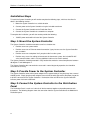
To install the System Controller you will need to complete the following steps, which are described in
detail in the following sections:
1. Mount the System Controller in a suitable location
2. Connect power to the System Controller using the included transformer
3. Connect the System Controller to the Distribution Panel
4. Connect the System Controller to a network or a computer
To complete the installation, you will also need to provide the following:
120VAC power outlet within 6 feet of the System Controller
"#$
The System Controller should be mounted to a wall at a location that:
Provides access to a power outlet
Provides access to an Ethernet network connection if you plan to access the System Controller
over a network
Provides access to a telephone line if you plan to dial in to the system
Provides easy access for cabling to interconnect the thermostat system: the included RS-485
serial communications cable is 3 ft long (additional cable can be used if needed)
The System Controller should be mounted in a dry location that maintains normal temperatures between
40 degrees F and 100 degrees F.
The System Controller does not need to be accessed in normal day-to-day operation, but should be
accessible for servicing.
%#
&'
(
The System Controller comes with a power adapter that is approximately 6’ long and plugs into a normal
120VAC outlet. Simply plug the power adapter into an electrical outlet and connect the power plug to the
6-30 VDC connector on the System Controller. Illumination of the red LED on the System Controller
indicates power has been established.
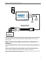
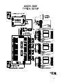
)#
The Distribution Panel is used as a hub to tie all the thermostats together and provide power to each
thermostat. The following diagram shows the connection from the System Controller to the Model 8818
Distribution panel.
&
Connect the enclosed Cat5 RS-485 serial communications pigtail cable between the System Controller
and the Distribution Panel. Plug the RJ45 connector into the RS-485 jack in the System Controller, and
connect the four individual wires as shown above into the terminals marked A+, A-, B+, B- on the
Distribution Panel.
*#
+ (
There are two methods to connect a computer to the System Controller: directly to a computer (with the
supplied crossover Ethernet cable); or using a local area network (with the supplied standard Ethernet
cable).
If there is no network available, then the System Controller is connected to a computer using the
enclosed crossover cable, which can be identified by the special label. Plug one end of the crossover
cable into the System Controller and the other end into the computer’s network port.
If there is a network available, then use the standard cable, plugging one end into the System Controller
and the other into an available Ethernet network jack.
' ( )*
)*/ , . *, (-' # ('
)*(.)++'.
Once you have completed the installation of System Controller you are ready to power up and configure
the System Controller for your application.
The Configurator is the software tool you use to setup and configure your system. The Configurator is a
point and click interface that you run from a computer during the installation, and later to make changes to
the system. Once the system has been set up, the Viewer interface described in Section 3 is used to
manage your system on a regular basis.
The Configurator communicates from your computer to the System Controller over an Ethernet network,
using either the included crossover cable or the included standard Ethernet cable.
The following section explains how to complete the network setup and configure the System Controller for
your network. Then, the Configurator is described in detail.
'+ (
To use the Configurator you need a computer with a Java-enabled web browser. In addition, your
computer and the System Controller need related IP addresses so they can communicate over the
network.
To update your computer with the latest version of Java:
The System Controller interfaces rely on a web browser that is Java enabled. You can update your
computer to the latest version of Java over the Internet at no charge: start a web browser and go to
www.java.com. Click the Get it Now link, and then follow the instructions.
To check your computer’s IP address:
The System Controller is sent from the factory with a default fixed IP address of 192.168.0.200. If your
computer has an IP address that begins with 192.168.0 then proceed to the next section: The
Configurator on page 12. If you don’t know the IP address of your computer, then proceed as follows:
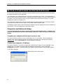
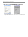
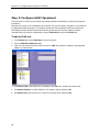
On Windows computers:
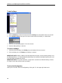
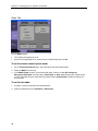
1. Click Start, Run to bring up the Run dialog similar to that shown below:
"
2. For Windows 95, 98, and Me (Millenium edition) type command, and for Windows NT, 2000 or
XP type cmd and then click OK: this will bring up a command prompt similar to that shown below.
3. Type ipconfig and press Enter: the system will display several lines including the IP address, as
shown above.
To change your IP address to setup the System Controller:
If your computer’s IP address begins with 192.168.0 then you can skip this step.
If your computer’s IP address does not begin with 192.168.0 then you need to temporarily change your
computer to connect to the System Controller and change its settings to match your network.
In the following procedure we’ll change your computer’s IP address so that you can communicate with the
System Controller. Once this is completed, you then connect to the System Controller to change its IP
address to match your network.
On Windows computers:
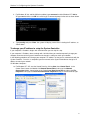
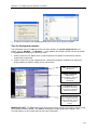
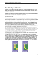
1a. For Windows NT / XP, start the Control Panel by clicking Start, then Control Panel. In the
Control Panel, locate and double-click Network Connections to bring up the Network
Connections dialog, shown below at left. Select Local Area Connection and then click File,
Properties to bring up the Local Area Connection Properties dialog, as shown below at right.
0
1b. For Windows 95, 98 and Me, click Start, Settings, Control Panel. In the Control Panel, locate
and double-click Network Connections to bring up the Network dialog.
2
For all versions of Windows, select the Internet Protocol (TCP/IP) (or TCP/IP) and then click
Properties, to bring up the TCP/IP dialogs similar to one of the following:
3
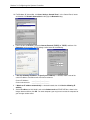
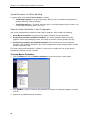
If Use the following IP address (or Specify an IP address) is selected, make a note of the
current IP address and Subnet mask for future reference:
Current IP Address:
_____._____._____._____
Current subnet mask:
_____._____._____._____
4
If Obtain an IP address automatically is selected instead, then click Use the following IP
address.
5
Set the IP address to 192.168.0.1 and set the Subnet mask to 255.255.255.0 as shown in the
images above and then click OK. On some computers you may have to restart the computer for
your changes to take effect.
To change the IP address of the System Controller to match your network
settings:
The following section describes how to change the IP address of the system controller. Perform this step:
if you have followed the previous steps to change you computer’s IP address so it starts with
192.168.0, and you are now ready to set the correct IP address for the System Controller, or
if your computer’s IP address does start with 192.168.0, but you want the IP address of the
System Controller to be something other than 192.168.0.200.
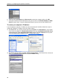
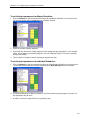
1. Start a web browser on your computer.
2. Place the cursor in the address field and type http://192.168.0.200 and then press Enter to bring up
the welcome page shown below.
3. If you don’t see the Aprilaire logo at the lower edge of the page (as shown above), stop and update
your computer as explained in To update your computer to the latest version of java on page 6.
4. Click Start the Configurator Now: after a short delay the Configurator will start.
5. The System tab is selected by default. Click General Data as shown above, and then click the IP
Settings button in the lower right: this brings up the settings dialog shown below:
$
6. Type in the desired IP address and Subnet mask to match your network, and then click OK.
7. If you plan to enable the email alert feature, then you must also set the Default Gateway and DNS
Server to correct values: see your network administrator if you are not sure what settings to use.
To restore your computer’s IP address:
If you changed your computer’s IP address to connect to the System Controller, follow these steps to
restore your computer’s IP address back to its original setting.
1a. For Windows NT / XP, start the Control Panel by clicking Start, then Control Panel. In the Control
Panel, locate and double-click Network Connections to bring up the Network Connections dialog,
shown below at left. Select Local Area Connection and then click File, Properties to bring up the
Local Area Connection Properties dialog, as shown below at right.
1b. For Windows 95, 98 and Me, click Start, Settings, Control Panel. In the Control Panel, locate and
double-click Network Connections to bring up the Network dialog.
1
2
For all versions of Windows, select the Internet Protocol (TCP/IP) (or TCP/IP) and then click
Properties, to bring up the TCP/IP dialogs similar to one of the following:
3
If you wrote down an IP address during step 4 of the procedure above (To change your IP address
to setup the System Controller), reset the IP address and subnet mask to those values. Otherwise,
click Obtain an IP address automatically.
4
Click OK: on some computers you may have to restart the computer for your changes to take effect.
There are four steps to setting up the System Controller with the Configurator, which are explained in the
following sections:
1. Set basic system-wide settings, such as system time and service override.
2. Add and configure thermostats, including setting the thermostat name and energy management
settings.
3. Add and configure the heating and cooling equipment.
4. Add and perform initial configuration of schedules which set, for example, the number of master
schedules (up to 4) and the number of periods per day. The actual setting of the temperature and
the start times is done with the Viewer as explained in Section 3.
To start the Configurator:
The Configurator is an easy to use interface that is accessed through a web browser.
1. Start a web browser on your computer.
2. Place the cursor in the address field and type http://192.168.0.200. If you changed the IP
address of the System Controller during the preceding steps, then enter that address instead of
192.168.0.200.
3. Press Enter: the System Controller welcome page is displayed.
To add a shortcut for the Configurator on your desktop:
To access the interface more quickly you can create a desktop shortcut that brings up the System
Controller welcome page with the following steps.
1. Click Create a Desktop Shortcut Now.
2. The File Download dialog appears as shown below: click Save. In the Save As dialog that appears,
click Desktop as shown below, then click Save.
3. A shortcut is placed on your desktop to provide quick access to the System Controller.
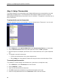
Tour the Configurator window:
The Configurator consists of tabs on the left side of the window, the system component tree and
buttons (such as Add New … and Remove …) in the middle of the window, and then various input fields
in the properties window on the right of the screen.
1. Select a tab on the left. Note that the system component tree updates to show devices that are
related to the selected tab.
2. Select an item in the system component tree. Note that the properties window on the right of the
display updates to show the settings for the selected item.
(2
!!
!
IMPORTANT NOTE: The Save button shown above appears when changes are made to settings but not
yet saved to permanent storage. Click Save to commit your changes to permanent storage. Any
unsaved changes are also saved when you close the Configurator.
!
"#
The System tab contains global settings which are typically set once during installation.
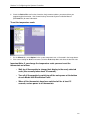
To set the System Controller time:
1. Click the System tab, then click System Time in the tree structure as shown below:
2. The properties window displays the System Controller’s current time as well as the time on your
computer. Check that the time shown for your computer is the correct time.
3. Click Set Time from this Computer. The time on your computer is used to set the time on the
System Controller.
To backup and restore System Controller settings:
You can make a backup copy of the system settings, such as the thermostats and their names, the
schedules and other system-wide data. If someone accidentally makes changes to the system, you can
later go back and restore the saved settings.
1. Click the System tab, then click Version Control in the tree structure as shown below.
2. In the properties window, click Backup System Data to make a copy of the current settings. Note the
Backup Date and Backup Version displayed at the bottom: this shows when you last backed up the
system data.
3. At any time in the future, click Restore System Data to restore your backed up settings.
4. The Restart System button restarts the System Controller, equivalent to cycling power to the System
Controller.
&
To change the passwords for the interfaces:
The System Controller supports two users: User and Admin.
User has access to the Viewer interface on a regular basis for making changes to setpoints, turning
heating on or off, etc.
Admin also has access to the Configurator for making changes to the setup of the system.
In normal installations it is common to have a password for Admin and no password for User. This
prevents accidental changes to the system setup, while allowing day-to-day users easy access to the
system.
1. Click the System tab, then click the desired user under Contacts and Users in the tree structure as
shown below:
2. Click Set Password to bring up the password dialog shown below:
3. Type in the new password in both boxes and click OK. Note that the System Controller is shipped
with no password set for either User or Admin.
IMPORTANT NOTE: If you would like a password for User, be sure to first setup a password for Admin.
IMPORTANT NOTE: If you would like to remove a password for User, click Set Password and leave
both fields blank, and then click OK. You will no longer be prompted for a password for that user.
%#
The System Controller can accommodate up to 16 Model 8870 thermostats connected with one or more
Model 8818 Distribution panels. Each thermostat on the thermostat network must have a unique ID.
Note that Model 8870 thermostats may also be set up as humidistats. Throughout this manual we refer to
both as thermostats.
To automatically scan for thermostats:
Automatic detection is best for new installations, and sets a default name (“Thermostat 1”, etc.) for each:
1. On the Climate tab, select Aprilaire Model 8818 under Communication Devices, as shown above.
2. Click the Discover Devices button at the lower right of the screen: click OK if prompted.
3. Wait for the process to complete: you will then see a list of the thermostats in the system component
tree.
4. To change the name of the thermostat:
Click the desired thermostat in the system component tree
Edit the Name box in the properties window and change the name as desired and press Enter.
To manually add thermostats:
This procedure is useful to add just one thermostat to a system that has already been setup.
1. On the Climate tab, select Thermostats in the tree structure.
2. Click the Add New … button.
3. Type in the desired name for the thermostat.
4. Click OK: the parameters window for the new thermostat appears on the right.
5. Select the newly added thermostat in the Thermostats section of the tree structure.
"
6. Check the Device ID to confirm that it matches the thermostat address you entered when you
programmed the thermostat. See Communicating Thermostat System Installation Manual
(#DP10005754) for more information.
To set the temperature scale:
1. On the Climate tab, select Options in the system component tree, as illustrated in the image above.
2. If the current setting for Scale is not correct, click the Scale drop down and select the desired scale.
Important Note: If you change the temperature scale you must reset the
thermostats as follows:
o Wait for all thermostats to change their display to the newly selected
scale (this normally takes about 30 seconds).
o Turn off all thermostats by switching off the main power at the bottom
of each Model 8818 Distribution Panel.
o When all the thermostats have been switched off for at least 15
seconds, restore power to all thermostats.
0
To set the Service Override:
The Model 8870 thermostats can be taken off the network temporarily for service issues by pressing the
Enter button on the thermostat. The status of the thermostat displayed in the Viewer changes to
“Network Override” in this situation, indicating that the thermostat is not responding to setpoint and mode
changes from the System Controller.
The System Controller will wait a period of time, and then force the thermostat back onto the network: this
time delay is the Service Override time.
1. On the Climate tab, select Options as shown above.
2. Click the Service Override drop down, and then select the desired time.
To set email settings for alerts:
The System Controller can be configured to send emails for alert conditions. The email will be sent to up
to three desired addresses, using the email server and the “From” address specified. See also To
specify and enable alerts below.
1. On the Climate tab, select the Aprilaire Model 8818 as above.
2. In the properties window at right, set the three email fields:
Email From: Set a valid email address. Some email servers will not forward mail if they cannot
validate the “From” address.
Email To: Set up to three desired email addresses to receive alerts.
Email Server: Set a valid email server to process the email.
IMPORTANT NOTE: Email alerts will only be sent when the System Controller is connected to a local
area network with an always-on Internet connection.
To set the Setpoint Limit and Hold Time for thermostats:
Users can change the setpoint from a thermostat by pressing the up or down buttons. The System
Controller will limit how far they can change the setpoint based on the Setpoint Limit. In addition,
changes made to the setpoint at the thermostat will be cancelled after the Hold Time, at which point the
scheduled setpoint will resume.
1. On the Climate tab, select the desired thermostat under Thermostats in the tree structure.
2. Click the Setpoint Limit drop down, then select the desired number of degrees above and below the
schedule that users can change the setpoint.
3. Repeat for the Hold Time setting.
To specify and enable alerts:
The System Controller can be configured to provide alerts if the temperature at a thermostat is too high or
too low, or if a thermostat fails to respond.
NOTE: Alerts are sent out immediately for temperature conditions being above or below the specified
alarm. Alerts are also generated if a thermostat fails to communicate for 10 minutes.
NOTE: To receive email notifications for alerts, you must also configure the email settings as described
above in To set email settings for alerts.
1. On the Climate tab, select the desired thermostat under Thermostats in the tree structure.
2. Click the Low Temp Alarm drop down and then select the desired temperature from the list.
3. Repeat for the High Temp Alarm setting.
4. Click the Enable Alarm drop down, and select Yes to turn on alerts.
$
To setup Remote Sensors:
The Model 8825 System Controller supports up to two remote sensors on each thermostat in the system.
Settings for sensors are in the property window for the thermostat to which they connect: in the image
above, Outside Temperature is the first sensor on the Reception thermostat, and there is no second
sensor connected.
1. Type the desired name for each remote sensor.
2. Set the Sensor 1 Alarm Low Value, if desired. For temperature sensors this number is in degrees,
and for humidity sensors this number is in % humidity.
3. Set the Sensor 1 Alarm High Value, if desired. As above, this can be either temperature or
humidity, depending on the sensor.
4. Set the Sensor 1 Enable Alarm, if desired. As above, click the Sensor 1 Enable Alarm drop-down
and select Yes to enable alerts for this remote sensor.
5. Repeat for sensor 2, if connected.
IMPORTANT NOTE: In order for remote sensor values to be displayed, the sensors must be set up as
sensor #1 and / or sensor #2 on module #1 of each thermostat. In addition, the sensors must also be
configured as “monitor” (as opposed to “control”) sensors.
IMPORTANT NOTE: The outside temperature, which is displayed on the System Status tab and in the
history graphs (explained in more detail later), must be connected as remote sensor #1 on thermostat #1.
1
To change the order of the thermostats in the Viewer:
You can change the order of thermostats in the Viewer to suit your own preference. The order of
thermostats controls the order of thermostats displayed on the System Status tab as well as the order of
the tabs on the Thermostat Settings tab. Typically, thermostats that control the most important spaces, or
thermostats that are checked most frequently, are placed at the top, or first in the list.
1. On the Climate tab, select Thermostats in the tree structure as shown above. In the properties
window to the right you will see all the currently installed thermostats, listed in order.
2. From the list, select the thermostat that you would like to change.
3. Click Move Up or Move Down to move the thermostat to its new position.
)#
,-. /
The term HVAC unit refers to the heating and cooling equipment controlled by a thermostat or group of
thermostats.
Based on the settings in the Configurator for the HVAC unit, specific controls will appear in the Viewer on
the appropriate thermostat page. For example, thermostats that control both heating and cooling will
have buttons for both, whereas thermostats that only control heat will not have cooling set points.
You add HVAC units with the Configurator using the HVAC Units branch of the Climate tab.
To add an HVAC unit:
1. In the Climate tab select HVAC Units in the tree structure.
2. Click the Add New HVAC Unit button.
3. Type in the desired name for the HVAC unit and click OK: the properties window for the equipment
appears as shown below.
4. Set Controls Heat: select Yes if this unit produces heat, No if this unit does not control heat.
5. Set Controls Cooling: as above, Yes if this unit controls cooling, otherwise No.
6. Set Controls Fan: Yes if the unit has a fan that can be turned on, otherwise No.
To assign HVAC units to thermostats:
Once the equipment has been added, go back to each thermostat and identify which equipment is
controlled by each thermostat.
1. In the Climate tab select the desired thermostat under Thermostats in the tree structure.
2. If the thermostat controls heating, select the appropriate HVAC unit next to the Heating Unit item in
the properties window to the right. In the example above, heat for the Reception thermostat is
provided by Unit1.
3. Similarly, if the thermostat controls cooling, select the appropriate HVAC unit next to the Cooling
Unit item in the properties window to the right. In the example above, cooling for the Reception
thermostat is also provided by Unit1.
!
Once equipment has been properly added and configured, the interface in the Viewer is automatically
generated to show the correct controls for each thermostat. At the bottom of the image below, the
Reception thermostat controls the heating and cooling for Unit 1. Unit 1, as shown to the right, provides
heating, cooling, and has a fan. At the upper left, the Viewer interface shows controls to turn on heating
or cooling, as well as a control for the fan.
"
#$ % %
!
!
&
!
*#
'
Schedules are set up and managed in two separate steps. The Configurator, described here, is used to
perform initial setup to create, name and provide the basic structure for schedules. The Viewer, which is
described later in Section 3, is used to change the actual start times and the setpoints and work with
schedules on a regular basis.
Schedules are used to change the desired temperature at different times of the day and for different days
of the week. This section provides an overview of how schedules are organized in the System Controller,
and then provides an example of the configuration in a typical office.
There are two types of schedules in the System Controller: Master Schedules and Individual Schedules.
Master Schedules can be applied to several thermostats at the same time. Master Schedules are a good
way to set many thermostats to the same schedule, so that you can make a change to the schedule in
one place and have the change automatically apply to many thermostats. In an office building, for
example, the Office Master Schedule could be used to control all the offices in a building, where
comfortable temperatures are maintained during normal business hours, while the Conference Master
Schedule could be used to control meeting spaces, where the temperatures are set to conserve energy
until the space is needed and someone temporarily adjusts the setting while the space is used.
Individual Schedules are local to each specific thermostat. Making changes to an Individual Schedule on
one thermostat does not change the settings on any other thermostat.
Both Master Schedules and Individual Schedules control settings for a one week period. Examples of
Master Schedules include the “5-2”, where Monday-Friday are the same and Saturday and Sunday share
the same settings, and the “5-1-1” where Monday-Friday are the same, and Saturday and Sunday get
their own program. Within any schedule, the week is split into one, two or three individual weekly
programs, which consist of those days that have the same settings.
Each weekly program is further broken down into periods for the day: a day can have up to four periods.
Periods are typically occupied or unoccupied.
th
To handle holidays, such as New Year’s or the 4 of July, weekly programs have an extra day of the
th
week. This special “8 ” day is treated like the other days, and can therefore be set with its own schedule
if desired. Normally, however, the holiday is simply set to have the same settings as the weekend days.
The following images are taken from the Configurator, and show two typical schedules graphically. The
left image shows the “5-2” schedule, where Monday through Friday share one program, and Saturday /
Sunday / Holiday share a different program. The image on the right shows the “5-1-1” where Saturday
and Sunday / Holiday have separate programs.
In a typical office, there would be one schedule, as follows:
Two Weekly Programs: One for the week days (Mon-Fri) and a second for the weekend and
holidays (Saturday, Sunday, Holidays)
Two Periods per Day: 1) Occupied, when the space is used during normal business hours, and
2) Unoccupied, when the space is not in use.
You use the Configurator to perform the initial setup of schedules, which includes the following:
1. Create Master Schedules: You add up to four Master Schedules for your application.
2. Set the basic parameters for Master Schedules: This entails setting the number of weekly
programs and the days belonging to each, and setting the number of events (periods) per day.
3. Set the basic parameters for Individual Schedules: Each thermostat has its own Individual
Schedule. Like the Master Schedules, you use the Configurator to set the weekly programs and the
number of periods per day.
The Viewer interface described later in Section 3 is then used on a regular basis to set the desired
temperatures and times for each schedule.
To create Master Schedules:
1. Click the Climate tab, then click Master Schedules in the tree structure as shown below:
2. Click Add New …, type in a name for the new Master Schedule in the dialog that appears, and then
click OK.
3. Repeat for any additional Master Schedules.
"
To set the basic parameters for Master Schedules:
1. Click the Climate tab, and then locate and click the desired Master Schedules in the tree structure.
The example below shows the Office Master Schedule selected:
2. Select the number of weekly programs.
3. Set the buttons so that each weekly program has the appropriate days highlighted. In the example
above, the schedule has two weekly programs: the first is Monday-Friday, the second is Saturday,
Sunday and Holidays.
4. Finally, select the number of events (Periods per day) for each day.
To set the basic parameters for Individual Schedules:
1. Click the Climate tab, and then locate and click the desired Individual Schedule in the tree structure.
The example below shows the Individual Schedule for the Back Hallway thermostat selected:
2. As explained above for the Master Schedules, select the number of weekly programs and then set
the appropriate days for each.
3. As above, select the number of events or periods per day.
0
To add holidays:
1. Click the Climate tab, and then locate and click the Holiday item at the bottom of the tree structure.
2. Click Add New Holiday, then type in the name and the date for the holiday, as shown below.
3. Click OK: the new holiday appears in the tree structure.
4. Continue adding holidays as desired.
To remove holidays:
1. Locate the desired holiday in the Holiday item at the bottom of the tree structure.
2. Click the holiday, then click Remove: the holiday is removed.
IMPORTANT NOTE: Holidays added as described above do not repeat, so that upcoming holidays must
be added periodically. It is recommended that old holidays be removed at the beginning of the year, and
that new holidays be added at that time.
IMPORTANT NOTE: The System Controller is shipped with a standard set of default Holidays, whereas
the images shown above do not show any holidays.
To close the Configurator:
When you are finished, close the Configurator by clicking the ‘X’ in the upper right-hand corner.
& '
(
' ( )* !
* , *, #) .
# ('
)*(.)++'.
The Viewer is the software interface that is used to manage the climate system on a regular basis. Like
the Configurator, the Viewer requires a computer with a Java-enabled web browser.
- (
As explained above for the Configurator, the Viewer can be started directly from a web browser. The
easiest way to access the Viewer is to place a shortcut to the System Controller welcome page on your
desktop, as explained for the Configurator.
To start the Viewer:
1. Locate and double-click your System Controller shortcut.
2. Or, start a web browser, place the cursor in the address field, and then type http://192.168.0.200 (or
your System Controller IP address if different) and press Enter. The System Controller welcome
page appears, as shown below.
3. If the Aprilaire logo does not appear as shown above, then you need to update your computer with
the latest version of Java.
4. Click Start the Viewer Now. The Viewer interface appears, showing the System Status tab.
$
& '
- (
(
!
The Viewer interface has three main tabs on the left of the screen: System Status, Thermostat
Settings, and Master Schedules.
The System Status tab provides a summary of all the thermostats and shows the outdoor temperature.
The System Status tab also shows the values for remote sensors and displays humidistats in a separate
window, if humidistats are present.
The Thermostat Settings tab provides access to each individual thermostat to control its setpoints, as
well as select which schedule the thermostat should use (Master or Individual Schedule).
The Master Schedules tab provides access to view and change the Master Schedules.
!1
& '
(
The System Status tab shows the current status of all the thermostats in the system. Each thermostat is
displayed in its own row with the following information:
NOTE: If the row for a thermostat is red, the thermostat currently has an active alert.
Name
The thermostat’s name
Heat
The current heating setpoint
Temp
The current room temperature
Cool
The current cooling setpoint
Status
The current status of the thermostat
Fan
The current status of the fan
Program
The current schedule status: Run, Timed Hold, or Permanent Hold.
Schedule
The thermostat’s current schedule
Systems that include humidistats have a second window listing humidistats:
Humidify
The current humidify setpoint
Humidity
The thermostat’s current humidity
Dehumidify The thermostat’s current dehumidify setpoint
Temperature and humidity sensors are displayed on the Sensors tab, as shown above right.
IMPORTANT NOTE: Only sensors configured as “monitor” (as opposed to “control”) are displayed on the
sensors tab.
IMPORTANT NOTE: The outside temperature is also shown down at the bottom: the outside temperature
is always taken from remote sensor #1 on thermostat #1.
!
& '
(
The Thermostat Settings tab contains a tab at the bottom for each thermostat in your climate system.
For each thermostat, tabs across the top allow you to access pages to control Temperature, Mode
(heating or cooling), control the thermostat’s Schedule and view the climate History.
The Temperature page allows you to:
View the current inside temperature, and if optional sensors are installed, view the remote
temperature or humidity.
Temporarily or permanently adjust the current setpoint.
When you make a change to the current setpoint of the thermostat, you are asking the system to maintain
a temperature that is different from the temperature called for by the current schedule. On the System
Controller, this is done either as a Timed Temporary Hold or as a Permanent Hold.
With Timed Temporary holds, the thermostat maintains the new setpoint for a pre-defined period of time,
which by default is four hours, with a plus or minus 5 degree change allowed to the setpoint. For
example, in an office where the temperature during the unoccupied period is set back, an employee
comes in to work for a short while. They press the buttons on the thermostat in their office to raise the
setpoint and make the space comfortable while they are there, and thereby start a Timed Temporary Hold
at that new setting. If they forget to set the temperature back when they leave, the system will
automatically set it back for them after the default four hours have elapsed.
Note that users can only change the setpoint a limited number of degrees by pressing the up and down
buttons on the actual thermostat. This is the Setpoint Limit, and is set in the Configurator: see To set the
Setpoint Limit and Hold Time for thermostats in Section 2.
If a setpoint should be held indefinitely, the controller offers a Permanent Hold. When this mode is active
the setpoint is maintained until a user switches back to either Run Program or Timed Temporary Hold.
!
& '
(
To temporarily adjust the setpoint at the thermostat:
1. At the thermostat, press the up and down buttons until the desired setpoint is reached.
2. If you change the setting so it is outside the range permitted by the Hold Limit, the System Controller
will reset the setpoint to bring it back within the allowed range.
3. The thermostat will hold the new temperature for the Hold Time and then return the setting to the
current schedule.
To temporarily adjust the setpoint with the Viewer interface:
4. On the Thermostat Settings page, select the tab for the desired thermostat.
5. Select the Temperature tab at the top.
6. Click the Up button to raise the setpoint temperature, or click the Down button to lower the setpoint
temperature. The temperature will change one degree each time you click the Up or Down button, or
press and hold the button for larger changes.
7. Note that in the Viewer interface, the temperature is not constrained by the Setpoint Limits, as it is
when making temporary changes at the thermostat.
8. Click the More Time or Less Time button if you would like to lengthen or shorten the duration of the
new setpoint.
To adjust the setpoint temperature with a Permanent Hold:
9. As above, select the tab for the desired thermostat and set the desired setpoint.
10. Then click the Permanent Hold button: the thermostat will hold the setpoints until someone sets the
thermostat back into Timed Temporary Hold or Run Program.
To return the thermostat to its currently active schedule:
11. On the Thermostat Settings page, select the tab for the desired thermostat.
12. Click the Run Program button: this will resume the active schedule for the thermostat.
!!
& '
(
Use the Mode page to:
Turn heating and cooling on or off.
Set the fan (if applicable) to run continuously or automatically when needed.
To set the climate control system mode:
1. On the Thermostat Settings page, select the tab for the desired thermostat.
2. Select the Mode tab at the top.
3. In the Mode Control section, select the desired mode. Choices include Off, Heating On,
Emergency Heating On (for heat pumps), Cooling On, or Auto, depending on your climate control
system. The button for your choice will turn yellow, and the System Status section will display the
current mode.
To set the fan mode:
1. As above, select the tab for the desired thermostat.
2. Select the mode for the fan: Automatic or Continuous.
!&
& '
(
There are two types of schedules on the System Controller: Individual Schedules and Master Schedules.
Individual Schedules apply only to a specific thermostat, so making changes to the Individual Schedule
on one thermostat does not change the setting on any other thermostat.
Master Schedules apply to all thermostats that have been set to follow that Master Schedule.
Use the Schedule page to:
Select which schedule to run on a thermostat. You can choose to run the thermostat’s Individual
Schedule or you can specify that the thermostat should run one of the Master Schedules.
Make changes to a thermostat’s Individual Schedule.
Copy a Master Schedule into the thermostat’s Individual Schedule.
Note that you cannot make changes to a Master Schedule from the individual thermostats: use the
Master Schedules tab at the left instead.
To change a thermostat’s currently active schedule:
1. On the Thermostat Settings tab, select the desired thermostat from the row of tabs at the bottom.
2. At the top of the page, the Active Schedule window shows which schedule is active. It can be the
Individual Schedule or one of the named Master Schedules.
3. Click Next or Prev until the desired schedule has been selected.
!
& '
(
To make changes to the thermostat’s Individual Schedule:
1. On the Thermostat Settings tab, select the desired thermostat from the row of tabs at the bottom.
2. If the active schedule is not the thermostat’s Individual Schedule, then use the Prev and Next buttons
until the Individual Schedule is displayed.
3. Use the buttons for each period to change the schedule as desired:
Press the left and right arrow buttons in the Start row to change the start time
Press the up and down arrow buttons in the Heat and Cool rows to change the desired setpoints.
Press the left and right buttons in the Fan row to specify the desired fan state for each period.
To copy a Master Schedule into the thermostat’s Individual Schedule:
If you would like to create an Individual Schedule for a thermostat that is very similar to an existing Master
Schedule, use this procedure to copy the Master Schedule into the thermostat’s Individual Schedule.
Then, go in and adjust the Individual schedule further.
1. On the Thermostat Settings tab, select the desired thermostat from the row of tabs at the bottom.
2. Use the Prev and Next buttons to select the Master Schedule that you wish to copy. Note that the
Save As Individual button is not active when the thermostat’s Individual Schedule is shown.
3. Click the Save As Individual button to the right: this sets the thermostat’s Individual Schedule so that
it matches the selected Master Schedule.
4. The current schedule automatically switches to the Individual Schedule.
5. Use the buttons on the schedule page to make the desired changes as shown above.
!"
& '
(
!
The History page is a useful tool to monitor the performance of the system and review recent activity for a
thermostat. Use the History page to:
Quickly view the standard display, which shows the system activity for the last 24 hours.
Change the display to show just the last hour, or the last week or month, or previous weeks or
months.
Check precisely when a certain event took place.
Show a custom period other than the standard hour, day, week or month.
To view the standard climate history display:
1. On the Thermostat Settings page, select the tab for the desired thermostat.
2. Click the History tab at the top. The screen displays three or four lines:
Green
= Room Temperature
White
= Outside Temperature
Red
= Heating Setpoint (Only shown if thermostat controls heating)
Blue
= Cooling Setpoint (Only shown if thermostat controls cooling)
3. The screen also displays a bar across the bottom to show if the thermostat is calling for heat or cool
as follows:
Red
= Calling for heat
Blue
= Calling for cool
Green
= The fan is on
!0
& '
(
To change the period shown in the History page:
1. Click Prev Day or Next Day to move back or forward a day.
2. Click Zoom In to see the last hour, or Zoom Out to see the last week. If you zoom out to show a
week, you can zoom out again to see the whole last month.
3. If you change the zoom, then the previous and next buttons will also change to show, for example,
Prev Week and Next Week.
To see the precise time on the history display:
It can be hard to determine precisely what time an event happened (such as a heating setpoint being
changed). The following instructions explain how to get the precise time for any point on the history
display graph.
1. Position the mouse so that the pointer is directly over the point of interest.
2. Click and hold the left mouse button, BUT DO NOT MOVE THE MOUSE.
3. The time at that location is shown, along with a vertical line corresponding to that time.
4. Release the left mouse button.
To use the mouse to show a very specific period of time:
To get finer control of the display, you can use the mouse to highlight and display a specific period of
interest:
1. Click the Zoom and Next / Previous buttons as explained above so that the period of interest is
entirely visible on the display.
2. Position your mouse at the left edge of the period of interest, then click and hold the left mouse button
while you drag the mouse to highlight the period of interest. When you release the left button, the
display will resize to show just that period.
!
& '
$
(
'
The Master Schedules tab provides access to the Master Schedules, and is used to view and make
changes to the Master Schedules.
Note that when changes are made to a Master Schedules, all thermostats currently running that Master
Schedule will use the new settings.
To make changes to a Master Schedule:
1. Select the desired Master Schedule from the row of tabs at the top.
2. Use the buttons for each period to change the selected Master Schedule as desired:
Press the left and right arrow buttons in the Start row to change the start time
Press the up and down arrow buttons in the Heat and Cool rows to change the desired setpoints.
Press the left and right buttons in the Fan row to specify the desired fan state for each period.
!$
& '
&1
(
Notes:
& '
(
&
& '
&
(
& '
(
&!
)
% .. *(#
& 0
1
'
Your Research Products Corporation System Controller is expressly warranted for five years from date of
installation to be free from defects in materials and workmanship.
Research Products Corporation’s exclusive obligation under this warranty shall be to supply, without
charge, a replacement for any System Controller which is found to be defective within such five (5) year
period and which is returned, together with the date of installation, no later than thirty (30) days after said
five (5) year period by you to either your original supplier or to Research Products Corporation, Madison,
Wisconsin, 53701.
THIS WARRANTY SHALL NOT OBLIGATE RESEARCH PRODUCTS CORPORATION FOR ANY
LABOR COSTS AND SHALL NOT APPLY TO DEFECTS IN WORKMANSHIP OR MATERIALS
FURNISHED BY YOUR INSTALLER AS CONTRASTED TO DEFECTS IN THE SYSTEM CONTROLLER
ITSELF.
IMPLIED WARRANTIES OF MERCHANTABILITY OF FITNESS FOR A PARTICULAR PURPOSE
SHALL BE LIMITED IN DURATION TO THE AFORESAID FIVE YEAR PERIOD. RESEARCH
PRODUCTS CORPORATION LIABILITY FOR INCIDENTAL OR CONSEQUENTIAL DAMAGES, OTHER
THAN DAMAGES FOR PERSONAL INJURIES, RESULTING FROM ANY BREACH OF THE
AFORESAID IMPLIED WARRANTIES OR THE ABOVE LIMITED WARRANTY IS EXPRESSLY
EXCLUDED. THIS LIMITED WARRANTY IS VOID IF DEFECT(S) RESULT FROM FAILURE TO HAVE
THIS SYSTEM CONTROLLER INSTALLED BY A QUALIFIED HEATING AND AIR CONDITIONING
CONTRACTOR. IF THE LIMITED WARRANTY IS VOID DUE TO FAILURE TO USE A QUALIFIED
CONTRACTOR, ALL DISCLAIMERS OF IMPLIED WARRANTIES SHALL BE EFFECTIVE UPON
INSTALLATION.
Some areas do not allow limitations on how long an implied warranty lasts or the exclusion or elimination
of incidental or consequential damages so the above exclusion or limitation may not apply to you.
This warranty gives you specific legal rights and you may also have other rights which vary from state to
state.
This equipment, if installed in strict accordance with the manufacturer’s instructions, complies with the
limits for a Class B computing device pursuant to Subpart J of Part 15 of FCC Rules.
Please … Take a few minutes to visit us on-line at www.aprilaire.com to register your Aprilaire product.
If you do not have on-line access, please mail a postcard with your name, address, phone number,
product purchased and date of purchase to:
Research Products Corporation
PO Box 1467
Madison, WI 53701
Thank you!
Your Warranty Registration Information will not be sold or shared outside of this company.
RESEARCH
PRODUCTS CORPORATION 1015 E. WASHINGTON AVE.
&&
61000159
B2203664F
MADISON, WI 53703
PHONE: 888/782-8638
FAX: 608/257-4357
www.aprilairecontractor.com