1
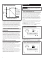
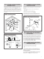
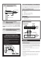
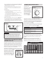
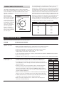
Automatic Steam Humidifier Control
Safety, Installation, and Operation Manual
READ COMPLETE INSTALLATION INSTRUCTIONS BEFORE STARTING.
WARNING
This product must be installed by a qualified heating and air conditioning contractor. Failure to do so
could result in serious injury from electrical shock or damage to product and voids product warranty due
to possible product misapplication.
THESE INSTALLATION INSTRUCTIONS ARE FOR THE AUTOMATIC STEAM HUMIDIFIER CONTROL ONLY!
For Aprilaire® Humidifier installation, follow Aprilaire Humidifier Installation Instructions.
WARNING
1. 240 volts may cause serious injury from electrical shock. Disconnect
electrical power to the Steam Humidifier before starting installation.
2. Sharp edges may cause serious injury from cuts. Use care when
cutting plenum openings and handling ductwork.
CAUTION
1. Do not set humidity higher than recommended. Condensation
damage may result.
2. Do not set humidity up to recommended levels if there is
condensation on the inside of windows. Condensation damage
may result.
3. Do not mount Automatic Steam Humidifier Control on supply
plenum or duct. High supply temperatures will cause the control
to malfunction.
4. When installing Automatic Steam Humidifier Control on downflow
furnaces, ensure blower continues to run after a heat call is
satisfied to eliminate high temperatures from damaging the
Automatic Steam Humidifier Control.
5. Do not configure Automatic Steam Humidifier Control for
Modulating Control (jumper JP2 set to 1 & 2) when connected to a
Model 1150 Steam Humidifier. Failure of humidifier may result.
PRINCIPLES OF OPERATION
The Aprilaire Automatic Steam Humidifier Control is designed to be
installed in the return duct of the HVAC system. The control strategy of the
Automatic Steam Humidifier Control is matched to the humidifier being
controlled: when used with a Model 1150 Aprilaire Steam Humidifier, the
Control supplies an on/off signal to the humidifier. When used with a
Model 1160 or 1180 Aprilaire Steam Humidifier, the Control supplies a
modulating signal to the humidifier. In terms of outdoor temperature
compensation, the Control can be set up in automatic or manual mode,
regardless of the humidifier model being controlled. The automatic mode
incorporates the supplied Outdoor Temperature Sensor to automatically
adjust the control set-point based on the outdoor temperature. The manual
mode does not require an outdoor temperature measurement and is used
for specific set-point control with the control set-point manually adjusted by
the user. The Automatic Steam Humidifier Control will accurately control
the humidity in the conditioned space within the range of 15% – 55% RH.
CONTROL TYPE
ON/OFF CONTROL FOR MODEL 1150
The Automatic Steam Humidifier Control sends a 10 VDC signal to the
humidifier when the measured return air relative humidity is 3% or more
below the set-point. This energizes the humidifier at 100% output. The
Steam Humidifier is either on at 100% capacity or it is off.
MODULATING CONTROL FOR MODEL 1160 & 1180
The Automatic Steam Humidifier Control sends a signal to the humidifier
between 0 and 10 VDC based on: a) the difference between measured
relative humidity and set-point relative humidity, and b) where this
difference or ‘error’ falls within an adjustable proportional control band.
The output of the Control, and therefore the Steam Humidifier, is a
‘proportion’ of maximum output based on ‘a’ and ‘b’ above. See Figure 1
for graphical representation of the output.
1
INSTALLATION
FIGURE 1 – Modulating Control Output
PROPORTIONAL
CONTROL BAND
OUTPUT
10 VDC
5 VDC
CAUTION
Note:
The Proportional
Control Band
can be adjusted
to 6%, 9%, 12%,
or 15% RH. The
factory setting
of 12% is
depicted at left.
0 VDC
-6
0
+6
MEASURED %RH - SETPOINT %RH
90-890
As an example, using the 12% proportional band (factory-setting), when the
measured RH is 6% above the set-point the output will be 0 VDC; when the
measured RH is 6% below set-point the output will be 10 VDC; when the
measured RH is 3% below set-point the output will be approximately 7.5
VDC. The humidifier uses this varying signal to time-proportion the
operation of the heating elements in the tank. 10 VDC output corresponds
with 100% humidifier capacity, 5 VDC with 50% capacity, etc. Modulating
control will result in a more precise control of relative humidity.
Improper jumper settings may damage humidifier.
The shunt on the JP2 header pin must be set in accordance with the
instructions in this manual.
STEP 1: VERIFY CONTROL TYPE
When shipped with a Steam Humidifier, the Automatic Steam Humidifier
Control is preset at the factory to match the humidifier model: Model 1150
Steam Humidifier is configured for on/off control while the Model
1160/1180 Steam Humidifier is configured for modulating control. When
shipped as a replacement (Model 57), the Control is preset for use with a
Model 1150 (i.e., on/off control). If using the Model 57 with a Model 1160
or 1180, the ‘control type’ setting must be changed for modulating control.
See below.
Remove the door to the Automatic Steam Humidifier Control and look at the
area on the circuit board above the terminal block. The three-pin header
labeled JP2 should be set in the following manner:
For the Model 1150, the Control must be set to the on/off configuration.
The shunt must be placed on the 2 & 3 pins. See Figure 2.
FIGURE 2 – On/Off Setting for Model 1150
OUTDOOR TEMPERATURE COMPENSATION
AUTOMATIC MODE
The automatic mode is the preferred method when the application
requires that the Control automatically adjust the RH set-point based on
the outdoor temperature. This is recommended for all comfort-based
applications such as office buildings, schools, day cares, etc. It is also
recommended for any application where the primary concern is to avoid
the potential for condensation that can form on areas within the building
such as windows and within walls. When installed in this mode, the
Control utilizes an Outdoor Temperature Sensor that will track the actual
outdoor temperature. The Control then automatically adjusts the desired
indoor RH.
MANUAL MODE (SPECIFIC SET-POINT CONTROL)
The manual mode is the preferred method when the application requires
that a specific set-point be maintained regardless of the outdoor
temperature. This is recommended for all process-based applications
such as print shops, book stores, test facilities, etc.
When installed in this mode, the Outdoor Temperature Sensor is replaced
with a “manual” resistor case that prevents the Control from adjusting
the space RH set-point based on the outdoor temperature, and controls
to the specific set-point selected on the Control.
Note: If the building is not designed to handle the amount of RH the
humidifier is supplying, the building occupants may need to adjust the RH
setting on the Control to a lower value during extreme days to prevent
condensation on interior surfaces. The RH setting should be adjusted
upward when the outdoor temperature goes up.
9
12
6
R17
1 2 3
15
I+
I- 24V
JP2
C
H+ H-
ODT
90-891
For the Model 1160 or 1180, the Control must be set to the modulating
configuration. The shunt must be placed on the 1 & 2 pins. See Figure 3.
FIGURE 3 – Modulating Setting for Model 1160 or 1180
9
12
6
R17
1 2 3
15
I+
I- 24V
JP2
C
H+ H-
ODT
90-892
2
STEP 2: DETERMINE LOCATION FOR CONTROL
AND MOUNT ON DUCT
STEP 3: DETERMINE LOCATION FOR OUTDOOR
TEMPERATURE SENSOR
The Control must be mounted in the return duct of the HVAC system.
See Figure 4 for a split-system installation and Figure 5 for a rooftop unit
installation. The Control must be at least 1 foot upstream of the steam
dispersion tube and any fresh air intake ductwork. Use the template in the
back of this manual to mark the duct opening. After cutting the hole in the
duct, mount the Control tightly to the duct using 4 sheet metal screws
(not provided).
The location of the Outdoor Temperature Sensor must meet these three
requirements:
1. Must be mounted on North, East or West side of building out of
direct sunlight
2. Must be at least 3 feet from all exhaust vents
3. Must be above expected snow line (See Figure 6)
Incorrect humidity levels will result if these requirements are not met.
Attach the sensor bracket to the building with a #8 galvanized screw.
FIGURE 4 – Split System Installation
FIGURE 6 – Outdoor Temperature Sensor Location
RETURN
AIR DROP
SUPPLY AIR
PLENUM
HIGH LIMIT
HUMIDITY
SWITCH
North, East
or West side
of building
AIR
FLOW
Outdoor
Temperature
Sensor
AUTOMATIC
STEAM
HUMIDIFIER
CONTROL
AIR W
FLO
POSSIBLE
DISPERSION
TUBE
LOCATIONS
SUPPLY
AIR DUCT
Sensor
AIR FLOW
PROVING
SWITCH
AIR
FLOW
Outdoor
Temperature
Sensor leads
Above expected
snow line
Sensor
Bracket
90-895
90-893
FIGURE 5 – Rooftop Unit Installation
Cooling Coil
Economizer
control device
Filters
Look for or provide an opening in the building envelope for running wire to
the Sensor. A convenient way to get wire to the Sensor is to make use of
unused wires running to the A/C condensing unit (if applicable). Other ways
are to use existing holes for telephone lines, A/C lines, water meter, etc.
Read all equipment instructions beforehand for possible conflicts and
warnings. Do not run outdoor temperature sensor wiring alongside
wires carrying high voltage (120VAC or higher).
Heating Coil
Outside
Air
Roof
Motorized
Air Dampers
Dispersion Tube B
Dispersion Tube A
AUTOMATIC
STEAM
HUMIDIFIER
CONTROL
Air Flow
Proving Switch
Duct High Limit
Humidity Control
from Dispersion
Point “A”
Return Duct
STEP 4: LOCATE ACCESS HOLE FOR WIRING TO
OUTSIDE SENSOR
STEP 5: ALTERNATE LOCATION FOR OUTDOOR
TEMPERATURE SENSOR
The Sensor can also be mounted in the center of either:
• PVC fresh air intake pipe for the split system furnace
OR
Supply Duct
90-894
• Fresh air intake duct. Mount the sensor with a #8 galvanized screw.
In both cases, the Sensor must be no more than 3 feet from the
outside wall. See Figure 7.
If it is not feasible to use the Outdoor Temperature Sensor in any of the
ways described, the Automatic Steam Humidifier Control can be set for
Manual Operation. See Figure 8 on the next page for details.
3
STEP 8: WIRE THE CONTROL TO THE HUMIDIFIER
FIGURE 7 – Alternate Location for Outdoor
Temperature Sensor
Wire the Control to the field wiring terminal block of the Steam Humidifier
according to Figure 9. Use 3-wire shielded cable with ground for the wiring
from the Control to the Humidifier. Note the terminal designations below.
AUTOMATIC STEAM HUMIDIFIER CONTROL:
FRESH AIR INTAKE
I+, I24V
C
H+
HODT
CENTER
LINE
36" MAX.
Serial Communications (for optional devices)
+24 VDC input power
Common
Command Signal to Steam Humidifier
Command Signal to ground (not used)
Outdoor Temperature Sensor
STEAM HUMIDIFIER:
OUTSIDE WALL
90-896
STEP 6: ROUTE THE WIRE TO CHOSEN
SENSOR LOCATION
Run wire to the outdoor temperature sensor. Sensor is not affected by lead
length up to 300 feet. Use standard thermostat wire. Do not run outdoor
temperature sensor alongside wires carrying high voltage (120 VAC
or higher).
STEP 7: ATTACH SENSOR WIRE TO AUTOMATIC
STEAM HUMIDIFIER CONTROL
Strip wires 1/4 inch, and insert the wires from the Sensor into the terminals
labeled “ODT” on the Automatic Steam Humidifier Control.
30
C
1
+24 VDC output power
Humidifier Common
Command Signal from Control
FIGURE 9 – Wiring Diagram
SERIAL COMMUNICATION
TO APRILAIRE MODEL 8570
THERMOSTAT (OPTIONAL)
AUTOMATIC
STEAM
HUMIDIFIER
CONTROL
I+
I-
2. Snap the Manual Mode Resistor Case into the slot
provided so that Resistor Case sticks out from the bottom
edge of the base.
3. Remove the control knob and apply the Manual Mode
label to the cover, aligning the sticker and knob holes.
Re-install the knob.
FIGURE 8 – Manual Mode
9
12
6
R17
1
15
I+
I- 24V
2
C
H+
H-
ODT
3-WIRE SHIELDED
CABLE W/GROUND
30
+24VDC
C
1
COMMON
COMMAND
SIGNAL
STEAM
HUMIDIFIER
FIELD WIRING
TERMINAL
BLOCK
90-900
OPERATION
SYSTEM CHECKOUT
1. For system test, be sure that all Steam Humidifier plumbing, distribution,
and electrical connections are set-up in accordance with the instructions
in the Steam Humidifier Installation, Operation, and Maintenance Manual
and all precautions therein are followed.
3
2. Turn on the water supply to the humidifier. Make sure the drain valve
is closed.
JP2
C
24V
HUMIDIFIER PANEL
SHIELD GND LUG
INSTALLING THE AUTOMATIC STEAM
HUMIDIFIER CONTROL FOR MANUAL OPERATION
1. Insert the Manual Mode Resistor Case into the terminals
labeled “ODT” on the Automatic Steam Humidifier Control.
TO OUTDOOR
TEMPERATURE
SENSOR
H+ H-
ODT
3. Turn on power to the humidifier.
4. Set up a fan call at the thermostat. If the humidifier is configured to bring
on the equipment fan when a demand for humidity is recognized, skip to
the next step.
90-899
4
5. Initiate a humidity demand from the Control by rotating the control
knob of the Automatic Steam Humidifier Control clockwise to the
‘Test’ position.
7. If the ‘Steam’ indicator light does not illuminate when the Control is
turned to the ‘Test’ position, refer to the troubleshooting section of
this manual.
8. Setting the Control:
• For Manual Mode and the conditioned space is occupied, set to 35%
or to a level that matches the application’s needs.
• If the conditioned space is unoccupied, set the Control to ‘Off’
The Automatic Steam
Humidifier Control is installed
in the return duct. During the
first heating season, the
Automatic Steam Humidifier
Control needs to be adjusted
to match the requirements and
construction of the conditioned
space. Please follow these
steps when adjusting the
Control (refer to Figure 12)
FIGURE 12
6
4
3
O
2
6
Red Diagnostic
Light
JP2
Turn the dial to a setting of “4”. At this setting, when the Outdoor
Temperature is 20°F, the indoor relative humidity set-point of the Automatic
Steam Humidifier Control will be 35% RH. During the next 24-48 hours, it
may be necessary to adjust the dial for more or less humidity, depending on
the occupants’ comfort and the requirements of the conditioned space.
Refer to the ‘Operation Guide’ (Table 1).
During the coldest portion of the first heating season, minor adjustments may
be necessary. This is dependent upon the unique features and construction of
the conditioned space. Refer to the ‘Operation Guide’ (Table 1).
R17
15
1
90-902
FIGURE 10
1 2 3
F
AUTOMATIC MODE
9. Make sure the Red Diagnostic Light on the Control (see Figure 10) is not
lit. If the Red Diagnostic Light is lit, re-check the wiring. If the Red
Diagnostic Light does not go off, refer to the troubleshooting section of
this manual. Note that the Red Diagnostic Light will turn on momentarily
when first powered up.
12
T
RE ES
S
5
For information on the initial adjustment period, refer to the operation
notes in the next section.
9
7
T/ T
E
• If using Automatic Mode and the conditioned space is occupied,
set the Control to knob-setting 4.
AUTOMATIC MODE OPERATION NOTES
F
6. If all is set up properly, the ‘Steam’ indicator light on the humidifier will
illuminate and the heaters will be energized. In the ‘Test’ position, the
humidity demand will last for one minute.
TABLE 1: Operation Guide
I+
I- 24V
C
H+ H-
Condition
Solution
Condensation on windows. Reduce the setting on the control
dial by 1 increment.
ODT
90-891
CAUTION
Lack of humidity.
Increase the setting on the control
dial by 1 increment.
A high relative humidity setting on the Control may cause
excessive condensation on windows and within walls. Set the
relative humidity in accordance with the instructions in this manual.
Do not set the relative humidity higher than recommended.
The relative humidity in the conditioned space will now be accurately
controlled and should need no further adjustment during future heating
seasons. Make note of the dial setting in the event the knob is temporarily
moved when performing annual maintenance of the Aprilaire Steam
Humidifier.
OPERATION NOTES FOR MODULATING CONTROL
FOR MODEL 1160 & 1180
Table 2 below shows the way the Automatic Steam Humidifier Control
automatically adjusts the relative humidity based on the outdoor
temperature. For example, when the knob is set to “4” and the outdoor
temperature is 20°F, the conditioned space will be controlled to 35% RH.
TABLE 2: Relative Humidity Guide
As explained in the ‘Principles of Operation’ section of this manual, when
configured for modulating control, the Automatic Steam Humidifier Control
sends a 0-10V signal to the humidifier to vary the capacity of the Steam
Humidifier depending on where the measured return air relative humidity
falls relative to the set-point as well as the proportional control band. This
will result in a more precise control of relative humidity.
Dial Setting
The proportional control band can be set to 6%, 9%, 12%, or 15% RH. The
factory-setting is 12%. Note that the proportional control band is centered
on the RH set-point. Refer back to Figure 1.
If the humidifier is cycling on and off too
FIGURE 11
frequently, the proportional control band
setting may need to be widened. To change,
9
12
use a small flat-head screwdriver to rotate
the potentiometer in the Automatic Steam
Humidifier Control board. See Figure 11.
6
15
Outdoor Temperature (°F)
-20
-10
0
10
20
30
40
50
1
–
2
–
–
–
10
15
20
25
30
–
12
17
22
27
32
37
3
–
13
18
23
28
33
38
43
4
15
20
25
30
35
40
45
50
5
22
27
32
37
42
47
52
55
6
28
33
38
43
48
53
55
55
7
35
40
45
50
55
55
55
55
90-901
5
MANUAL MODE OPERATION NOTES
OU
40
HUMIDITY 4
35%
F
2
TD
%
OOR
T/ T
E
TEMPER
AT
UR
2 0° F
E
The Automatic Steam Humidifier Control is installed in the return duct.
When installed in the Manual Mode, the Control provides specific set-point
control. If the building is not designed to handle the amount of RH the
humidifier is supplying, the RH setting on the Control may need to be
adjusted to a lower value
during extreme days to
FIGURE 13
prevent condensation on
interior surfaces. For example,
with an outdoor temperature
55%
°F
T
of 20°F the correct setting will
RE ES
%
5
S
be 35% relative humidity. If
the temperature is expected to
fall to 0°, then reduce the
setting to 25% several hours
prior to the temperature
F
5%
O
change. It is important to
F
15 %
adjust the RH setting upward
MANUAL
MODE
when the outdoor temperature
90-904
goes back up again.
The recommended settings on the humidistat are based on years of research
for an average building. (See ASHRAE Handbook – HVAC Systems and
Equipment, Ch. 20 – Humidifiers.) Note: these settings may not be appropriate
for every application. These settings represent a compromise between RH levels
that would be most desirable for comfort reasons and humidity levels that are
suitable for protection of the conditioned space and to avoid condensation on
windows and within walls. For example, a wintertime indoor RH of 50% may
be considered ideal for comfort, but unfortunately, it probably would result in
damage to the conditioned space. Observance of the recommended RH levels
on the humidistat, therefore, is an important safeguard. Condensation of
water on inside windows in the form of fogging or frost is an indication of too
much relative humidity. This same condensation can occur in other areas of
the conditioned space with the possibility of damage resulting.
TABLE 3: Outdoor–Indoor Relative Humidity
0°
Outside Temperature
+40˚F
+30˚F
+20˚F
+10˚F
0˚F
-10˚F
-20˚F
Recommended RH
45%
40%
35%
30%
25%
20%
15%
TROUBLESHOOTING GUIDE
Applies to both Automatic and Manual Operation unless indicated otherwise.
SYMPTOM
TROUBLESHOOTING PROCEDURE
Humidifier does not
operate in “Test” mode
• Make sure equipment blower is operating and thermostat is calling for heat.
• Make sure the Outdoor Temperature Sensor is connected to the “ODT” terminals of the control.
(For Manual Operation, make sure Manual Mode Resistor Case is in place of the Sensor).
• Check main wiring diagram for correct Automatic Steam Humidifier Control installation.
• Check voltage at Automatic Steam Humidifier Control “24V” and “C” terminals.
Voltage should be 22 VDC minimum – 26 VDC maximum.
• In “Test” mode, humidifier will operate for 1 minute only. DO NOT LEAVE IN TEST MODE AS HUMIDIFIER WILL NOT OPERATE.
• Make sure water supply valve is open.
• If humidifier still does not operate, refer to the Aprilaire Steam Humidifier Installation, Operation, and Maintenance Manual.
Humidifier operates only
in “Test” mode
• If outdoor temperature is greater than 60°F or less than -30°F, the Automatic Steam
Humidifier Control will only operate in the “Test” mode. (Automatic Mode Only)
• If the humidity level in the building is higher than the knob setting or the proportional
control band (Model 1160 and 1180 only), the Automatic Steam Humidifier Control will not
operate the Humidifier.
• Check the resistance of the sensor by removing the leads of the Outdoor Temperature
Sensor from the terminals and measuring the resistance across the wires with an
ohmmeter. Confirm reading to outdoor temperature in Table 4. (For Manual Operation,
remove leads and verify that resistance across the leads of Manual Mode Resistor Case
is between 44,000 and 48,000 ohms).
• Make sure the Outdoor Temperature Sensor is mounted completely outside the building on the
North, East, or West side of the building and out of direct sunlight. (Automatic Mode Only)
• If Outdoor Temperature Sensor is mounted in fresh air intake duct, make sure the probe is
no more than 36 inches from the outside wall. (Automatic Mode Only)
• Make sure the Outdoor Temperature Sensor is located at least 3 feet away from all
exhaust vents. (Automatic Mode Only)
6
TABLE 4
Outdoor
Resistance
Temperature
kΩ
-30˚F
230.6
-20˚F
163.8
-10˚F
117.6
0˚F
85.4
10˚F
62.6
20˚F
46.3
30˚F
34.6
40˚F
26.1
50˚F
19.9
60˚F
15.3
70˚F
11.9
80˚F
9.4
90˚F
7.4
100˚F
5.9
SYMPTOM
TROUBLESHOOTING PROCEDURE
Humidifier operates
constantly
• If the humidity level in the building is less than the knob setting or is within the proportional control band (Model 1160 and
1180 only), the Automatic Steam Humidifier Control will operate the humidifier until the humidity level is higher than the
knob setting.
• In the “Test” mode, verify unit will operate for approximately one minute.
• Check the resistance of the sensor by removing the wires of the Outdoor Temperature Sensor and measuring the resistance
across the wires with an ohmmeter. Confirm reading to outdoor temperature in Table 4. (For Manual Operation, verify that
resistance across the leads of Resistor Case is between 44,000 and 48,000 ohms.)
• Make sure the Outdoor Temperature Sensor is mounted completely outside the building on the North, East, or West side of
the building and out of direct sunlight. (Automatic Mode Only).
• Rotate the Automatic Steam Humidifier Control knob counterclockwise to the “Off” position, and observe whether the
humidifier turns off (‘Steam’ indicator light on the humidifier should go off). If the humidifier still operates in the “Off”
position, check summary wiring diagram for correct Automatic Steam Humidifier Control installation.
• If humidifier still does not shut off, refer to the troubleshooting section in the Aprilaire Steam Humidifier Installation,
Operation, and Maintenance Manual.
Humidifier or Automatic
Steam Humidifier Control
“chatters” or clicks ON
and OFF rapidly
• Check voltage at Automatic Steam Humidifier Control “24V” and “C” terminals.
Voltage should be 22 VDC minimum – 26 VDC maximum.
Red Diagnostic Light is on
• Check that the wiring is correct. See Figure 9.
• Make sure Outdoor Temperature Sensor wiring is not run alongside wires carrying high voltage (120 VAC or higher).
(Automatic Only)
• Measure the resistance of the Outdoor Temperature Sensor by removing the leads from the terminal and measuring
the resistance across the wires with an ohmmeter. Confirm the reading with the temperature in Table 4.
(For Manual Operation, verify that the resistance across the leads of the Manual Mode Resistor Case is between
44,000 and 48,000 ohms).
CUT ALONG DASHED LINE
AUTOMATIC STEAM
HUMIDIFIER
CONTROL TEMPLATE
WARNING
Sharp edges on the opening may cause cuts. Use care when cutting the plenum opening and
installing the Automatic Steam Humidifier Control.
CAUTION
• Do not mount Automatic Steam Humidifier Control on supply plenum or duct. The unit will not
withstand supply temperatures and will malfunction!
• When installing Automatic Steam Humidifier Control on counterflow furnaces, ensure blower
continues to run after a heat call is satisfied to eliminate high temperatures from damaging the
Automatic Steam Humidifier Control.
• Do not mount Automatic Steam Humidifier Control downstream of the bypass outlet.
False humidity conditions will cause humidifier to operate incorrectly.
1. CUT TEMPLATE ALONG DASHED LINE.
2. PLACE THIS TEMPLATE ON THE RETURN PLENUM UPSTREAM OF (BEFORE) THE
DISPERSION TUBE.
3. TRACE THE OUTSIDE EDGES OF THIS TEMPLATE.
4. REMOVE TEMPLATE AND ACCURATELY CUT THE PLENUM OPENING.
5. USING 4 SHEET METAL SCREWS, INSTALL AUTOMATIC STEAM HUMIDIFIER CONTROL
IN PLENUM OPENING.
LIMITED WARRANTY
Your Research Products Corporation Aprilaire Automatic Steam Humidifier Control is expressly warranted for two (2) years from the date of installation to be
free from defects. Research Products Corporation’s exclusive obligation under this warranty shall be to supply, without charge, a replacement for any part of
the Automatic Steam Humidifier Control, which is found to be defective within a two (2) year period and which is returned no later than thirty (30) days after
the two (2) year period by you or your original supplier to Research Products Corporation, Madison, WI 53701, together with the model number and installation
date of the Automatic Steam Humidifier Control.
THIS WARRANTY SHALL NOT OBLIGATE RESEARCH PRODUCTS CORPORATION FOR ANY LABOR COSTS AND SHALL NOT APPLY TO DEFECTS IN
WORKMANSHIP OR MATERIALS FURNISHED BY YOUR INSTALLER AS CONTRASTED TO DEFECTS DISCOVERED IN THE AUTOMATIC STEAM HUMIDIFIER
CONTROL ITSELF.
IMPLIED WARRANTIES OF MERCHANTABILITY OR FITNESS FOR A PARTICULAR PURPOSE SHALL BE LIMITED IN DURATION TO THE AFORESAID TWO-YEAR
PERIOD. RESEARCH PRODUCTS CORPORATION’S LIABILITY FOR INCIDENTAL OR CONSEQUENTIAL DAMAGES, OTHER THAN DAMAGES FOR PERSONAL
INJURIES, RESULTING FROM ANY BREACH OF THE AFORESAID IMPLIED WARRANTIES OR THE ABOVE LIMITED WARRANTY IS EXPRESSLY EXCLUDED. THIS
LIMITED WARRANTY IS VOID IF DEFECT(S) RESULT FROM FAILURE TO HAVE THIS UNIT INSTALLED BY A QUALIFIED HEATING AND AIR CONDITIONING
CONTRACTOR. IF THE LIMITED WARRANTY IS VOID DUE TO FAILURE TO USE A QUALIFIED CONTRACTOR, ALL DISCLAIMERS OF IMPLIED WARRANTIES
SHALL BE EFFECTIVE UPON INSTALLATION.
SOME STATES DO NOT ALLOW LIMITATIONS ON HOW LONG AN IMPLIED WARRANTY LASTS OR THE EXCLUSION OR LIMITATION OF INCIDENTAL OR
CONSEQUENTIAL DAMAGES SO THE ABOVE EXCLUSION OR LIMITATIONS MAY NOT APPLY TO YOU.
This warranty gives you specific legal rights and you may also have other rights, which vary, from state to state.
WARRANTY REGISTRATION
To register your Aprilaire product or for more information, visit
www.aprilairecontractor.com
If you do not have on-line access, please mail a postcard with your name, address, phone number,
product purchased and date of purchase to:
Research Products Corporation
P.O. BOX 1828
Madison, WI 53701
Thank you!
Your Warranty Registration information will not be sold or shared outside of this company.
CUT ALONG DASHED LINE
1015 E. Washington Ave. • Madison, WI 53703
Phone: 888/782-8638 • Fax: 608/257-4357
www.aprilairecontractor.com
61000134 06.06
B2203636B
©2006 Research Products Corporation