1
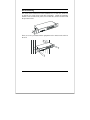
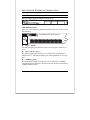
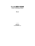
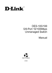
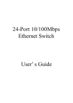
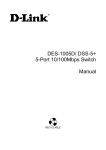
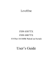
24-Port 10/100Mbps Dual-Speed Switch User’s Guide Version 1.0 P/N: ATM020423SR24 Rev.A This User's Guide contains important information regarding the installation of your switch. Please read it completely before beginning installation. For future reference, record the serial number of your network switch in the space below: SERIAL number The serial number is located on the bottom of the switch. Amer.com 7259 Bryan Dairy Road, Largo, FL 33777 USA © Amer.com Corp., 1997-2002 All rights reserved. No part of this publication may be reproduced in any form or by any means or used to make any derivative such as translation, transformation, or adaptation without permission from Amer.com, as stipulated by the United States Copyright Act of 1976. Amer.com reserves the right to make changes to this document and the products which it describes without notice. Amer.com shall not be liable for technical or editorial errors or omissions made herein; nor for incidental or consequential damages resulting from the furnishing, performance, or use of this material. Amer.com is a registered trademark of Amer.com. names are properties of their owners. All other trademarks and trade FCC Class A Certification Statement Model SR24 FCC Class A This device complies with Part 15 of the FCC rules. Operation is subject to the following two conditions: (1)This device may not cause harmful interference, and (2)This device must accept any interference received, including interference that may cause undesired operation. This equipment has been tested and found to comply with the limits for a Class A digital device, pursuant to Part 15 of the FCC Rules. These limits are designed to provide reasonable protection against harmful interference in a residential installation. This equipment generates, uses and can radiate radio frequency energy and, if not installed and used in accordance with the instructions, may cause harmful interference to radio communications. However, there is no guarantee that interference will not occur in a particular installation. If the equipment does cause harmful interference to radio or television reception, which can be determined by turning the equipment off and on, the user is encouraged to try to correct the interference by one or more of the following measures: • Reorient or relocate the receiving antenna. • Increase the separation between the equipment and receiver. • Connect the equipment into an outlet on a circuit different from that to which the receiver is connected to. • Consult the dealer or an experienced radio/TV technician for help. Shielded interface cables must be used in order to comply with emission limits. You are cautioned that changes or modifications not expressly approved by the party responsible for compliance could void your authority to operate the equipment. For more information please contact the Federal Communication Commission. CE Mark Class A Statement In a domestic environment, this product may cause radio interference in which case the user may be required to take adequate measures. TABLE OF C ONTENTS About This Guide ......................................................... 1 PURPOSE ..........................................................................................1 OVERVIEW OF THIS USER’S GUIDE ................................................1 Introduction .................................................................. 2 FAST ETHERNET TECHNOLOGY.....................................................2 SWITCHING TECHNOLOGY .............................................................3 FEATURES ........................................................................................4 Unpacking and Installation........................................... 6 UNPACKING .....................................................................................6 INSTALLATION.................................................................................6 RACK MOUNTING............................................................................7 Identifying External Components................................. 8 FRONT PANEL ..................................................................................8 REAR PANEL ....................................................................................9 Technical Specification............................................... 10 iv A BOUT T HIS G UIDE Congratulations on your purchase of the 24-port 10/100Mbps Auto-negotiation Fast Ethernet Switch. This device integrates 100Mbps Fast Ethernet and 10Mbps Ethernet network capabilities in a highly flexible package. Purpose This guide discusses how to install your 24-port 10/100Mbps Fast Ethernet Switch. TERMS/USAGE In this guide, the term “Switch” (first letter upper case) refers to your 24-port 10/100Mbps Fast Ethernet Switch, and ”switch” (first letter lower case) refers to other Ethernet switches. Overview of this User’s Guide Introduction. Describes the Switch and its features. Unpacking and Installation. Helps you get started with the basic installation of the Switch. Identifying External Components. Describes the front panel, rear panel and LED indicators of the Switch. Technical Specifications. Lists the technical (general, physical and environmental, and performance) specifications of the Switch. 1 I NTRODUCTION This chapter describes the features of the Switch and some background information about Ethernet/Fast Ethernet switching technology. Fast Ethernet Technology The growing importance of LANs and the increasing complexity of desktop computing applications are fueling the need for high performance networks. A number of high-speed LAN technologies have been proposed to provide greater bandwidth and improve client/server response times. Among them, 100BASE-T (Fast Ethernet) provides a non-disruptive, smooth evolution from the current 10BASE-T technology. The non-disruptive and smooth evolution nature, and the dominating potential market base, virtually guarantee cost effective and high performance Fast Ethernet solutions in the years to come. 100Mbps Fast Ethernet is a standard specified by the IEEE 802.3 LAN committee. It is an extension of the 10Mbps Ethernet standard with the ability to transmit and receive data at 100Mbps, while maintaining the CSMA/CD Ethernet protocol. Since the 100Mbps Fast Ethernet is compatible with all other 10Mbps Ethernet environments, it provides a straightforward upgrade and takes advantage of the existing investment in hardware, software, and personnel training. 2 Switching Technology Another approach to pushing beyond the limits of Ethernet technology is the development of switching technology. A switch bridges Ethernet packets at the MAC address level of the Ethernet protocol transmitting among connected Ethernet or Fast Ethernet LAN segments. Switching is a cost-effective way of increasing the total network capacity available to users on a local area network. A switch increases capacity and decreases network loading by dividing a local area network into different segments, which don’t compete with each other for network transmission capacity. The switch acts as a high-speed selective bridge between the individual segments. The switch, without interfering with any other segments, automatically forwards traffic that needs to go from one segment to another. By doing this the total network capacity is multiplied, while still maintaining the same network cabling and adapter cards. For Fast Ethernet networks, a switch is an effective way of eliminating problems of chaining hubs beyond the “two-repeater limit.” A switch can be used to split parts of the network into different collision domains, making it possible to expand your Fast Ethernet network beyond the 205-meter network diameter limit for 100BASE-TX networks. Switches supporting both traditional 10Mbps Ethernet and 100Mbps Fast Ethernet are also ideal for bridging between the existing 10Mbps networks and the new 100Mbps networks. Switching LAN technology is a marked improvement over the previous generation of network bridges, which were characterized by higher latencies. Routers have also been used to segment local area networks, but the cost of setup and maintenance required make routers relatively impractical. Today switches are an ideal solution to most kinds of local area network congestion problems. 3 Features The Switch is designed for easy installation and high performance in an environment where traffic on the network and the number of users increase continuously. The Switch with its rack size is specifically designed for middle to large workgroups. The Switch provides immediate access to a rapidly growing network through a wide range of user-reliable functions. The Switch is ideal for deployment with multiple high-speed servers for shared bandwidth 10Mbps or 100Mbps workgroups. With the highest bandwidth 200Mbps (100Mbps in full-duplex mode), any port can provide workstations with a congestion-free data pipe for simultaneous access to the server. The Switch is expandable by cascading two or more switches together. As all ports support 200Mbps, the Switch can be cascaded from any port and to any number of switches. The Switch is a perfect choice for site planning to upgrade to Fast Ethernet in the future. Ethernet workgroups can connect to the Switch now, and change adapters and hubs anytime later without needing to change the Switch or reconfigure the network. The Switch combines dynamic memory allocation with store-and-forward switching to ensure that the buffer is effectively allocated for each port, while controlling the data flow between the transmit and receive nodes to guarantee against all possible packet loss. The Switch is an unmanaged 10/100 Fast Ethernet Switch that offers solutions in accelerating small Ethernet workgroup bandwidth. Other key features are: 9 9 24-port 10/100BASE Ethernet Switch with RJ-45 connectors Supports Auto-negotiation for speed and duplex modes for each port 4 9 9 9 9 9 9 9 9 9 9 Supports Auto-MDI/MDI-X for each port Wire speed reception and transmission Store-and-Forward switching method Integrated address Look-Up Engine, supports 8K absolute MAC addresses Supports 2.5Mbytes RAM for data buffering Front-panel diagnostic LEDs Broadcast storm protection IEEE 802.3x flow control for full-duplex Back pressure flow control for half-duplex Standard 19” Rack-mountable size 5 U NPACKING AND I NSTALLATION This chapter provides unpacking and setup information for the Switch. Unpacking Open the shipping carton of the Switch and carefully unpack its contents. The carton should contain the following items: 9 9 9 9 9 The 24-port 10/100Mbps Fast Ethernet Switch One AC power cord, suitable for your area’s electrical power connections Four rubber feet to be used for shock cushioning Screws and two mounting brackets This User’s Guide If any item is missing or damaged, please contact supplier for replacement. Installation The site where you install the Switch stack may greatly affect its performance. When installing, consider the following pointers: Install the Switch in a fairly cool and dry place. See Specifications for the acceptable temperature and humidity operating ranges. Install the Switch in a site free from strong electromagnetic field generators (such as motors), vibration, dust, and direct exposure to sunlight. Leave at least 10cm of space at the front and rear of the unit for ventilation. Install the Switch on a sturdy, level surface that can support its weight, or in an EIA standard-size equipment rack. For information on rack installation, see the next section, Rack Mounting. When installing the Switch on a level surface, attach the rubber feet to the bottom of the device. The rubber feet cushion the unit and helps protect the case from scratching. 6 Rack Mounting The switch can be mounted in an EIA standard-size, 19-inch rack, which can be placed in a wiring closet with other equipment. Attach the mounting brackets at the switch’s front panel (one on each side), and secure them with the provided screws. Then, use screws provided with the equipment rack to mount each switch in the rack. 7 I DENTIFYING E XTERNAL C OMPONENTS This section identifies all the major external components of the switch. Front Panel The figure below shows the front panels of the switch. 10/100Mbps Dual Speed Switch 1 2 3 4 5 6 7 8 9 10 11 12 13 14 15 16 17 18 19 20 21 22 13 14 15 16 17 18 19 20 21 22 23 24 1 2 3 4 5 6 7 8 9 10 11 12 23 24 LINK Power 100Mbps 24-port 10/100Mbps Fast Ethernet Switch LED Indicator Panel Refer to the next chapter for detailed information about each of the switch’s LED indicators. 10/100Mbps Dual Speed Switch 1 2 3 4 5 6 7 8 9 10 11 12 13 14 15 16 17 18 19 20 21 22 23 24 LINK Power 100Mbps Power (PWR) This indicator lights green when the switch is receiving power, otherwise, it is off. Link / Activity ( green ) This indicator lights green when the port is connected to a Fast Ethernet or Ethernet station. The indicator blinks green when transmitting or receiving data. 100Mbps ( green ) This LED indicator lights green when the port is connected to a 100Mbps Fast Ethernet station. Otherwise, the LED is off when the port is connected to a 10Mbps Ethernet station. 8 Twisted-Pair Ports These ports support the automatic MDI/MDIX crossover detection function which provides true ‘plug and play’ capability without the need of confusing crossover cables or crossover ports. With the Auto-MDI function, you simply plug-in the network cable to the unit directly with no need to care if the end node is a NIC (Network Interface Card) or switches and hubs. Rear Panel AC Power Connector 9 T ECHNICAL S PECIFICATION General Standards Protocol Data Transfer Rate Topology Network Cables Number of Ports IEEE 802.3 10BASE-T Ethernet IEEE 802.3u 100BASE-TX Fast Ethernet CSMA/CD Ethernet: 10Mbps (half duplex), 20Mbps (full-duplex) Fast Ethernet: 100Mbps (half duplex), 200Mbps (full-duplex) Star 10BASET: 2-pair UTP Cat. 3,4,5, EIA/TIA-568 100-ohm STP 100BASE-TX: 2-pair UTP Cat. 5, EIA/TIA-568 100-ohm STP 24 x 10/100Mbps Auto-MDI ports Physical and Environmental AC inputs 100 to 240 VAC, 50 or 60 Hz internal universal power supply Power Consumption 10 watts. (max.) Temperature Operating: 0° ~ 40° C, Storage: -10° ~ 70° C Humidity Operating: 10% ~ 90%, Storage: 5% ~ 90% Dimensions 440 x 140 x 44 mm (W x H x D) EMI: FCC Class A, CE Mark Class A, VCCI Class A Safety CUL, CB 10 Performance Transmits Method: Store-and-forward RAM Buffer: 2.5MBytes per device Filtering Address Table: 8K entries per device Packet Filtering/Forwar ding Rate: MAC Address Learning: 10Mbps Ethernet: 14,880/pps 100Mbps Fast Ethernet: 148,800/pps Automatic update 11 Amer.com Warranty Policy Limited Lifetime Warranty In the event of a defect in quality or workmanship, Amer.com will repair or replace any hardware product sold by Amer.com with new or reconditioned parts free of charge in North America for a limited lifetime period unless otherwise specified on the sales invoice from the date of original purchase. All removed parts become the property of Amer.com. All replaced parts assume the original warranty. This warranty is extended only to the original purchaser. before warranty service is provided. Proof of purchase will be required This warranty covers only failures due to defects in quality or workmanship that occur during normal use. It does not cover damage that occurs in shipment, electrical storms, floods, dropped or other acts of nature. This warranty also does not cover any failure that results from accident, misuse, abuse, neglect, mishandling, misapplication, alteration, faulty installation, modification, computer virus, improperly installed or faulty software, or service by anyone other than an Amer.com Service Technician. If there is evidence that the failure was due to user negligence, Amer.com has the right to void this warranty and or charge normal service rates for the subject repair. The limited warranty covers a one (1) year period from date of purchase on Power Supplies, AC Adapters & Fans, after the 1 year a cost for replacement is applied to all products requiring such parts. Amer.com is not responsible for any type of data loss on hard drive or other storage devices. Warranty Service can be obtained during the warranty period by shipping, freight prepaid, or delivering the product to Amer.com in either the original package or a similar package providing an equal degree of protection. Amer.com will perform the required service and return the unit to the user (freight prepaid), if applicable, via the same mode (i.e. ground, air, etc.) 12 Limits and Expectations There are no express warranties except as listed above. Network products by Amer.com shall not be liable for incidental or consequential damages resulting from the use of this product. Any future upgrades, including (but not limited to) hardware and software are not covered by this limited warranty. If a hardware problem with this product develops during the warranty period, you may contact the Amer.com Service Center at: Telephone Facsimile (727) 549-0772 (727) 549-0992 Service Center Amer.com 7259 Bryan Dairy Road Largo, Florida 33777 U.S.A. 13