1
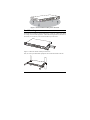
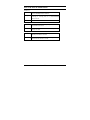
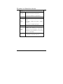
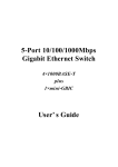
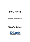
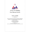
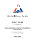
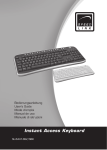
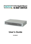
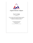
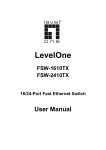
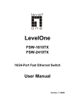
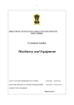
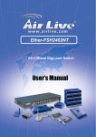
SR24G2
24 Port 10/100 Switch with
2 Ports 10/100/1000
User’s Guide
Version 1.0
P/N: SR24G2030303 Rev.1
This User's Guide contains important information
regarding the installation of your switch. Please read it
completely before beginning installation.
For future reference, record the serial number
of your network switch in the space below:
SERIAL number
The serial number is located on the bottom of the switch.
Amer.com
7259 Bryan Dairy Road, Largo, FL 33777
© Amer.com Corp., 1997-2003 All rights reserved. No part of this publication
may be reproduced in any form or by any means or used to make any derivative
such as translation, transformation, or adaptation without permission from
Amer.com, as stipulated by the United States Copyright Act of 1976.
Amer.com reserves the right to make changes to this document and the
products which it describes without notice. Amer.com shall not be liable for
technical or editorial errors or omissions made herein; nor for incidental or
consequential damages resulting from the furnishing, performance, or use of
this material.
Amer.com is a registered trademark of Amer.com. All other trademarks and
trade names are properties of their owners.
FCC Class A Certification Statement
Model SR24G2 FCC Class A
This device complies with Part 15 of the FCC rules. Operation is subject to the
following two conditions: (1)This device may not cause harmful interference,
and (2)This device must accept any interference received, including
interference that may cause undesired operation.
This equipment has been tested and found to comply with the limits for a Class
A digital device, pursuant to Part 15 of the FCC Rules. These limits are
designed to provide reasonable protection against harmful interference in a
residential installation. This equipment generates, uses and can radiate radio
frequency energy and, if not installed and used in accordance with the
instructions, may cause harmful interference to radio communications.
However, there is no guarantee that interference will not occur in a particular
installation. If the equipment does cause harmful interference to radio or
television reception, which can be determined by turning the equipment off and
on, the user is encouraged to try to correct the interference by one or more of
the following measures:
• Reorient or relocate the receiving antenna.
• Increase the separation between the equipment and receiver.
• Connect the equipment into an outlet on a circuit different from that to
which the receiver is connected to.
• Consult the dealer or an experienced radio/TV technician for help.
Shielded interface cables must be used in order to comply with emission limits.
You are cautioned that changes or modifications not expressly approved by the
party responsible for compliance could void your authority to operate the
equipment. For more information please contact the Federal Communication
Commission.
CE Mark Class A Statement In a domestic environment, this product may cause
radio interference in which case the user may be required to take adequate
measures.
TABLE
OF
C ONTENTS
ABOUT THIS GUIDE ............................................................................. 1
PURPOSE .................................................................................................. 1
TERMS/USAGE ......................................................................................... 1
INTRODUCTION .................................................................................... 2
FAST ETHERNET TECHNOLOGY .............................................................. 2
GIGABIT ETHERNET TECHNOLOGY ......................................................... 2
SWITCHING TECHNOLOGY ...................................................................... 3
FEATURES ................................................................................................ 3
UNPACKING AND INSTALLATION .................................................. 5
UNPACKING ............................................................................................. 5
INSTALLATION......................................................................................... 5
RACK MOUNTING .................................................................................... 6
CONNECTING NETWORK CABLE ............................................................. 7
AC POWER .............................................................................................. 7
IDENTIFYING EXTERNAL COMPONENTS .................................... 8
FRONT PANEL .......................................................................................... 8
REAR PANEL ............................................................................................ 9
UNDERSTANDING LED INDICATORS ........................................... 10
POWER LED .......................................................................................... 10
PORTS 1~24 STATUS LEDS ................................................................... 10
PORT 25 & PORT 26 STATUS LEDS ...................................................... 11
TECHNICAL SPECIFICATIONS ....................................................... 12
A BOUT T HIS G UIDE
Congratulations on your purchase of the 24-Port 10/100Mbps Ethernet
Switch with 2 × 1000BASE-T Gigabit ports. This device integrates
Gigabit, 100Mbps Fast Ethernet, and 10Mbps Ethernet network
capabilities in a highly flexible package.
Purpose
This guide discusses how to install your 24-Port 10/100Mbps with 2×
1000BASE-T ports Switch.
Terms/Usage
In this guide, the term “Switch” (first letter upper case) refers to your 26Port 10/100/1000Mbps Switch with 2 × 1000BASE-T plus 24 ×
10/100BASE-TX ports, and “switch” (first letter lower case) refers to
other Ethernet switches.
1
I NTRODUCTION
This chapter describes the features of the Switch and some background information
about Ethernet/Fast Ethernet/Gigabit Ethernet switching technology.
Fast Ethernet Technology
The growing importance of LANs and the increasing complexity of desktop computing
applications are fueling the need for high performance networks. A number of highspeed LAN technologies have been proposed to provide greater bandwidth and improve
client/server response times. Among them, 100BASE-T (Fast Ethernet) provides a nondisruptive, smooth evolution from the current 10BASE-T technology. The nondisruptive and smooth evolution nature, and the dominating potential market base,
virtually guarantee cost-effective and high performance Fast Ethernet solutions.
100Mbps Fast Ethernet is a standard specified by the IEEE 802.3 LAN committee. It is
an extension of the 10Mbps Ethernet standard with the ability to transmit and receive
data at 100Mbps, while maintaining the CSMA/CD Ethernet protocol. Since the
100Mbps Fast Ethernet is compatible with all other 10Mbps Ethernet environments, it
provides a straightforward upgrade and takes advantage of the existing investment in
hardware, software, and personnel training.
Gigabit Ethernet Technology
Gigabit Ethernet is an extension of IEEE 802.3 Ethernet utilizing the same packet
structure, format, and support for CSMA/CD protocol, full duplex, flow control, and
management objects, but with a tenfold increase in theoretical throughput over 100Mbps Fast Ethernet and a hundredfold increase over 10-Mbps Ethernet. Since it is
compatible with all 10-Mbps and 100-Mbps Ethernet environments, Gigabit Ethernet
provides a straightforward upgrade without wasting a company’s existing investment in
hardware, software, and trained personnel.
The increased speed and extra bandwidth offered by Gigabit Ethernet are essential to
coping with the network bottlenecks that frequently develop as computers and their
busses get faster and more users using applications that generate more traffic.
Upgrading key components, such as your backbone and servers to Gigabit Ethernet can
greatly improve network response times as well as significantly speed up the traffic
between your subnets.
Gigabit Ethernet supports video conferencing, complex imaging, and similar dataintensive applications. Likewise, since data transfers occur 10 times faster than Fast
2
Ethernet, servers outfitted with Gigabit Ethernet NIC’s are able to perform 10 times the
number of operations in the same amount of time.
The phenomenal bandwidth delivered by Gigabit Ethernet was the most cost-effective
method to take advantage of today’s rapidly improving switching and routing
internetworking technologies. And with expected advances in silicon technology and
digital signal processing that enabled Gigabit Ethernet to eventually operate over
unshielded twisted-pair (UTP) cabling, outfitting your network with a powerful 1000Mbps-capable backbone/server connection creates a flexible foundation for the next
generation of network technology products.
Switching Technology
Another approach to pushing beyond the limits of Ethernet technology is the
development of switching technology. A switch bridges Ethernet packets at the MAC
address level of the Ethernet protocol transmitting among connected Ethernet or Fast
Ethernet LAN segments.
Switching is a cost-effective way of increasing the total network capacity available to
users on a local area network. A switch increases capacity and decreases network
loading by dividing a local area network into different segments, which don’t compete
with each other for network transmission capacity.
The switch acts as a high-speed selective bridge between the individual segments. The
switch, without interfering with any other segments, automatically forwards traffic that
needs to go from one segment to another. By doing this the total network capacity is
multiplied, while still maintaining the same network cabling and adapter cards.
Switching LAN technology is a marked improvement over the previous generation of
network bridges, which were characterized by higher latencies. Routers have also been
used to segment local area networks, but the cost of a router, the setup and maintenance
required make routers relatively impractical. Today switches are an ideal solution to
most kinds of local area network congestion problems.
Features
.
24×10/100BASE-TX Fast Ethernet ports + 2×1000BASE-T Gigabit Ethernet
ports
.
Auto MDI-X for each port
.
Full/half duplex transfer mode for 10/100Mbps Fast Ethernet ports
.
Full duplex transfer mode for Gigabit Ethernet ports
3
.
Wire speed reception and transmission
.
Store-and-Forward switching method
.
Integrated address Look-Up Engine, supports 8K MAC addresses
.
Supports 512K bytes RAM for data buffering
.
Extensive front-panel diagnostic LEDs
.
IEEE 802.3x flow control for full-duplex
.
Back pressure flow control for half-duplex
.
Standard 19” Rack-mount size
4
U NPACKING AND I NSTALLATION
This chapter provides unpacking and installation information for the Switch. To avoid
causing any damage to the Switch, we recommend that you read this chapter carefully
before starting installation.
Unpacking
Open the shipping carton of the Switch and carefully unpack the items inside. The
carton should contain the following items:
ˇ One 24-Port 10/100Mbps Ethernet Switch with 2 Ports 10/100/1000Mbps
ˇ One AC power cord, suitable for your area’s electrical power connections
ˇ Four rubber feet to be used for shock cushioning
ˇ Screws and two mounting brackets
ˇ User’s Guide
If any item is found missing or damaged, please contact your local reseller for
replacement.
Installation
The site where you place the Switch may greatly affect its performance. When
installing, take the following into your consideration:
Install the Switch in a fairly cool and dry place. See Technical Specifications for the
acceptable temperature and humidity operating ranges.
Install the Switch in a site free from strong electromagnetic field generators (such as
motors), vibration, dust, and direct exposure to sunlight.
Leave at least 10cm of space at the front and rear of the hub for ventilation.
Install the Switch on a sturdy, level surface that can support its weight, or in an EIA
standard-size equipment rack. For information on rack installation, see the next section,
Rack Mounting.
When installing the Switch on a level surface, attach the rubber feet to the bottom of
each device. The rubber feet cushion the hub and protect the hub case from scratching.
5
Figure 1. Attach the adhesive rubber pads to the bottom
Rack Mounting
The Switch can be mounted in an EIA standard-size, 19-inch rack, which can be placed
in a wiring closet with other equipments. Attach the mounting brackets to both sides of
the Switch (one at each side), and secure them with the provided screws.
Figure 2. Combine the Switch with the provided screws
Then, use screws provided with the equipment rack to mount the Switch in the rack.
6
Figure 3. Mount the Switch in the rack
Connecting Network Cable
The Switch supports 10/100/1000Mbps Gigabit Ethernet. It runs full/half duplex
transfer mode for 10/100Mbps and full duplex transfer mode for 1000Mbps.
These ports are Auto-MDI type. The Switch can auto configure to MDI-II or MDI-X
type, so you can make a connection without worrying if you are using a standard or
crossover cable.
AC Power
The Switch can be used with AC power supply 100~240V AC, 50~60 Hz. The power
switch is located at the rear of the unit adjacent to the AC power connector and the
system fan. The switch’s power supply will adjust to the local power source
automatically and may be turned on without having any or all LAN segment cables
connected.
7
I DENTIFYING E XTERNAL C OMPONENTS
This chapter identifies all the major external components of the Switch. Both the front
and rear panels are shown below, with a description of each panel feature.
Front Panel
10/100 BASE-T X Twisted-Pair Ports
LED Indicators
1000 BASE-T
Twisted-Pair Ports
Figure 4. The front panel of the Switch
LED Indicators
Refer to the next chapter Understanding LED Indicators for detailed information
on the meaning of each LED indicator.
10/100BASE-TX Twisted-Pair Ports (Port1~24)
These ports supports network speeds of either 10Mbps or 100Mbps, and can
operate in half- and full- duplex transfer modes. These ports also support
automatic MDI/MDI-X crossover detection function which gives true “plug
and play” capability. Just plug-in the network cable to the hub directly since
there is no need to care if the end node is NIC (Network Interface Card) or
switches and hubs.
1000BASE-T Twisted Pair Ports (Port 25~26)
The Switch is equipped with two Gigabit twisted pair ports that are auto
negotiable 10/100/1000Mbps and auto MDI/MDIX crossover detection
supported. These two ports can operate in half- and full- duplex modes.
8
Rear Panel
Power Switch
Power Connector
Figure 5. The rear panel of the Switch
AC Power Connector
This is a three-pronged connector that supports the power cord. Plug in the
female connector of the provided power cord into this connector, and the male
into a power outlet. Supported input voltages range from 100~240V AC at
50~60Hz.
Power Switch
Use the power switch beside this power connector to turn on or turn off the power
of the Switch.
9
U NDERSTANDING LED I NDICATORS
The front panel LEDs provide instant status feedback, and, helps monitor and
troubleshoot when needed.
Figure 6. LED indicators of the Switch
Power LED
POWER
On
: When the Power LED lights on, the Switch is receiving
power.
Off
: When the Power LED turns off or the power cord has
improper connection.
Ports 1~24 Status LEDs
LINK/ACT
On
: When the LED lights on, the respective port is connected to the
10/100Mbps Ethernet network.
Blinking
: When the LED is blinking, the port is transmitting or receiving data on
the 10/100Mbps Ethernet network.
Off
: No link.
100Mbps
On
: When the LED lights on, the respective port is connected to
a 100Mbps Ethernet network.
Off
: The respective port is connected to a 10Mbps Ethernet
network, or no link
10
Port 25 & Port 26 Status LEDs
LINK/ACT
On
: When the LED lights on, the respective port is connected to
a 10/100/1000Mbps Ethernet network.
Blinking
: When the LED is blinking, the respective port is
transferring or receiving data on a 10/100/1000Mbps
Ethernet network.
Off
: No link.
1000Mbps
On
: When the LED lights on, the respective port is connected to
a Gigabit Ethernet network.
Off
: The respective port is connected to a 10/100Mbps Ethernet
network, or no link.
100Mbps
On
: When the LED lights on, the respective port is connected to
a 100Mbps Fast Ethernet network.
Off
: The respective port is connected to a 10Mbps or Gigabit
Ethernet network, otherwise, no link.
11
T ECHNICAL S PECIFICATIONS
General
IEEE 802.3 10BASE-T Ethernet
Standards
IEEE 802.3u 100 BASE-TX Fast Ethernet
IEEE 802.3ab 1000BASE-T Gigabit Ethernet
Protocol
CSMA/CD
Ethernet: 10Mbps (half duplex), 20Mbps (full
duplex)
Data
Transfer
Rate
Fast Ethernet: 100Mbps (half duplex), 200Mbps
(full duplex)
Gigabit Ethernet: 2000Mbps (full duplex)
Topology
Star
10BASET: 2-pair UTP/STP Cat. 3,4,5; up to 100m
Network
Cables
Number
Ports
100BASE-TX: 2-pair UTP/STP Cat. 5; up to 100m
1000BASE-T: 4-pair UTP/STP Cat. 5; up to 100m
(Cat. 5E is recommended)
of
24 ×10/100BASE-TX Auto-MDIX STP ports
2 × 1000BASE-T Auto-MDIX STP ports
12
Physical and Environmental
AC inputs:
100 to 240V AC, 50/60 Hz internal universal
power supply
Power
Consumption:
20 watts. (max.)
Temperature:
Operating: 0°~40°C, Storage: -10°~70°C
Humidity:
Operating: 10%~90%, Storage: 5%~90%
Dimensions:
440× 200× 44 mm (W × H × D)
Emissions:
FCC Class A, CE Mark Class A,
VCCI Class A
Safety:
cUL(1950), CB(IEC60950)
Performance
Transmits Method:
Store-and-forward
RAM Buffer:
512K bytes per device
Filtering Address
Table:
8K entries per device
Packet
Filtering/Forwardi
ng Rate:
10Mbps Ethernet: 14,880/pps
100Mbps Fast Ethernet: 148,800/pps
1000Mbps Gigabit Ethernet: 1488,000/pps
MAC
Address
Learning:
Automatic update
13
Amer.com Warranty Policy
Limited Lifetime Warranty
In the event of a defect in quality or workmanship, Amer.com will repair or replace any
hardware product sold by Amer.com with new or reconditioned parts free of charge in
North America for a limited lifetime period unless otherwise specified on the sales
invoice from the date of original purchase. All removed parts become the property of
Amer.com. All replaced parts assume the original warranty.
This warranty is extended only to the original purchaser. Proof of purchase will be
required before warranty service is provided.
This warranty covers only failures due to defects in quality or workmanship that occur
during normal use. It does not cover damage that occurs in shipment, electrical storms,
floods, dropped or other acts of nature.
This warranty also does not cover any failure that results from accident, misuse, abuse,
neglect, mishandling, misapplication, alteration, faulty installation, modification,
computer virus, improperly installed or faulty software, or service by anyone other than
an Amer.com Service Technician. If there is evidence that the failure was due to user
negligence, Amer.com has the right to void this warranty and or charge normal service
rates for the subject repair.
The limited warranty covers a one (1) year period from date of purchase on Power
Supplies, AC Adapters & Fans, after the 1 year a cost for replacement is applied to all
products requiring such parts.
Amer.com is not responsible for any type of data loss on hard drive or other storage
devices.
Warranty Service can be obtained during the warranty period by shipping, freight
prepaid, or delivering the product to Amer.com in either the original package or a
similar package providing an equal degree of protection. Amer.com will perform the
required service and return the unit to the user (freight prepaid), if applicable, via the
same mode (i.e. ground, air, etc.)
14
Limits and Expectations
There are no express warranties except as listed above.
Network products by Amer.com shall not be liable for incidental or consequential
damages resulting from the use of this product. Any future upgrades, including (but not
limited to) hardware and software are not covered by this limited warranty. If a
hardware problem with this product develops during the warranty period, you may
contact the Amer.com Service Center at:
Telephone (727) 549-0772
Facsimile (727) 549-0992
Service Center
Amer.com
7259 Bryan Dairy Road
Largo, Florida
33777
U.S.A.
15