1
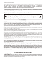
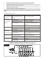
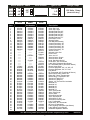
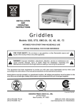
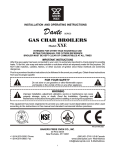
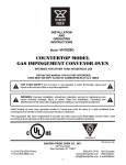
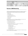
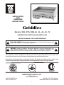
INSTALLATION
AND
OPERATING
INSTRUCTIONS
Griddles
Models: XSG, XTG, XMG-24, -36, -48, -60, -72
INTENDED FOR OTHER THAN HOUSEHOLD USE
RETAIN THIS MANUAL FOR FUTURE REFERENCE
!
FOR YOUR SAFETY: Do not store or use gasoline or other flammable vapors and
liquids in the vicinity of this or any other appliance.
!
!
WARNING: Improper installation, adjustment, alteration, service or maintenance can
cause property damage, injury or death. Read the Installation, Operating and
Maintenance Instructions thoroughly before installing or servicing this equipment.
!
This equipment has been engineered to provide you with year round dependable service when used
according to the instructions in this manual and standard commercial kitchen practices.
Instructions must be posted in a prominent location. All safety precautions must be taken in the
event the user smells gas. Safety information can be obtained from your local gas supplier.
S IGN
DE
R
CE
R TIFIED R
CERTIFIED
SANITATION
NSF/ANSI 4
R
P/N U4179A 1/08
BAKERS PRIDE OVEN CO., INC.
30 Pine Street
New Rochelle, NY 10801
(914) 576-0200 Phone
(914) 576-0605 Fax
(800) 431-2745 US & Canada
www.bakerspride.com Web Address
1
CONTENTS
1. Installation Instructions
A Safety Precautions
B Unpacking Instructions
C Gas Connections
D Electric Installation (XSG model only)
E Leveling Adjustment
2. Lighting Instructions
GAS SPECIFICATIONS
Propane Gas
BTU/HR @ 10” W.C.
Model Number
XSG, XTG, XMG
XSG, XTG, XMG
XSG, XTG, XMG
XSG, XTG, XMG
XSG, XTG, XMG
A Lighting Instructions
B Shutdown Instructions
3. Cleaning Instructions
4. Maintenance Instructions
5. Wiring Diagram (XSG Only)
6. Parts List & Exploded View
7. Warranty
2
2
3
3
3
4
4
60,000
90,000
120,000
150,000
180,000
-24
-36
-48
-60
-72
4
4
5
5
6
7
11
Natural Gas
BTU/HR @ 3.5” W.C.
60,000
90,000
120,000
150,000
180,000
XSG units are equipped with snap action thermostats and standing pilot systems. This griddle must have
115V, 60 Hz electrical power to operate the main burners. This appliance will not operate during a power
failure. No attempt should be made to operate this gas appliance during power failure.
XTG units are equipped with throttle type thermostat and standing pilot (no pilot safety provided)
XMG units are equipped with manual gas valves, and standing pilot (no pilot safety provided). No griddle
plate temperature control is provided.
1. INSTALLATION INSTRUCTIONS
A.
SAFETY PRECAUTIONS
FOR YOUR SAFETY, THE FOLLOWING SAFETY PRECAUTIONS SHOULD BE FOLLOWED AND
ENFORCED.
IF YOU SMELL GAS:
!
SHUT OFF GAS SUPPLY TO APPLIANCE
!
EXTINGUISH OPEN FLAMES
!
IMMEDIATELY CALL YOUR GAS SUPPLIER
1.
2.
3.
4.
5.
6.
7.
A separate gas shut-off valve should be installed in the gas line ahead of the unit, as required by
codes.
LIGHTING: Follow the instructions on page 5.
At least 24 inches must be provided at the front of unit for servicing.
When installing, never enclose the bottom area of the unit with a raised curb or other construction
that would obstruct the flow of air into the unit.
This unit may be operated with 0” (side and back) minimum clearance to non-combustible
construction materials.
This installation must conform to local codes, or in absence of local codes to the National Fuel Gas
Code ANSI Z223.1, latest edition. In Canada it must conform to current National Standard
CAN/CGA B 149.1 (natural gas) or CAN/CGA B 149.2 (propane) Installation Code for Gas Burning
Appliances & Equipment.
In MASSACHUSETTS: All gas products must be installed by a “Massachusetts” licensed plumber
or gas fitter. Ventilation hoods must be installed in accordance with NFPA-96, current edition, with
interlocks as described in that standard.
2
8.
9.
10.
11.
12.
13.
Electrical diagram (model XSG only) is located on the right side of the unit.
The appliance and its individual shut-off valve must be disconnected from the gas supply piping
system during any pressure testing of that system at test pressures in excess of 1/2” psi (3.45 kPa).
The appliance must be isolated from the gas supply piping system by closing its individual manual
shut-off valve during any pressure testing of the gas supply piping system at test pressures equal to
or less than ½” psi (3.45kPa).
This appliance must be installed under a ventilation hood.
Do not obstruct the flow of combustion and ventilation air.
The area around this or any other gas appliance must always be kept free and clear from
combustibles.
RETAIN THIS MANUAL FOR FUTURE REFERENCE.
B. UNPACKING INSTRUCTIONS:
Carefully unpack the griddle and inspect immediately for shipping damages. Your Griddle was shipped in a
carton designed to give maximum protection in normal handling. It was thoroughly inspected before leaving
the factory and the carrier accepted and signed for it. File any claims for shipping damage or irregularities
with the carrier.
C. GAS CONNECTIONS
A separate gas shut off valve (supplied with unit) must be installed in the gas line ahead of the unit, as
required by codes (see Fig. A).. Gas supply line must be ¾” or larger. If flexible semi rigid connections are
used, the inside diameter must be the equivalent of ¾” iron pipe or larger. All connections of the flexible and
semi rigid type must be AGA listed and comply with applicable ANSI standards. Make sure gas piping is
clean and free of dirt, piping compound and
obstruction. To insure maximum operating Figure “A”
Main Shut-Off Valve
efficiency, this appliance must be connected with a
Flue
Pressure
Regulator
Gas Supply Line of solid pipe or with a Commercial
Type Flexible Connector with I.D. (inside diameter)
equal or larger than the gas pipe inlet on this
appliance.
CAUTION: BEFORE LIGHTING, CHECK ALL
JOINTS IN THE GAS SUPPLY LINE FOR LEAKS.
USE SOAP AND WATER SOLUTION. DO NOT
USE OPEN FLAME.
If the gas connections are leak-free, the unit is ready
to use. Follow the lighting instructions.
D. ELECTRIC INSTALLATION (XSG ONLY)
This appliance when installed must be electrically grounded in accordance with local codes, or in
the absence of local codes, with the National Electrical Code, ANSI/NFPA 70, or the Canadian
Electrical Code, CSA C22.2, as applicable.
The installation of electric wiring from the electric meter, the main control box, and the outlet to the electric
appliance must be electrically grounded in accordance with local codes, or in the absence of local codes
with the National Electric Code ANSI/NFPA 70. In Canada, follow the Canadian Electric Code CSA-C 22.2.
All work should be done by qualified installation personnel.
Electrical diagram (model XSG only) is located on the right side of the unit.
WARNING-ELECTRICAL GROUNDING INSTRUCTION
This appliance is equipped with a three-prong (grounding) plug for your protection against shock
3
hazard and should be plugged directly into a properly grounded three-prong receptacle. Do not cut
or remove the grounding prong from this plug.
Thermostats do not have to be turned off to turn off your griddle. The ON/OFF toggle switch allows the
thermostats to remain set at your cooking temperature when the griddle is OFF. When the main switch is
ON the griddle automatically heats to your pre-set cooking temperature.
Red indicator lights next to the thermostats are ON when the burners are in operation. When the set
temperature is reached, the light will go OFF.
E. LEVELING ADJUSTMENT
All griddles are equipped with adjustable legs to provide a means for proper leveling during installation. The
griddle can be leveled by turning the bottom of the legs until the desired position is achieved. After leveling,
the manifold should then be connected to the gas line.
2. LIGHTING INSTRUCTIONS
A. LIGHTING INSTRUCTIONS
1. Turn off all thermostats or gas controls and main Shut-off valve and wait 5 minutes.
2. Turn the main gas valve to ON position and light standing pilots through the holes in the front panel.
(FIG. B) The pilot assembly is located about 10” into the unit from the front panel. Use a BBQ match
or a lighter at least 10” long. Alternatively pilots are also accessible from the bottom of the unit and
the distance is approximately 6”. Insert a match or a lighter from the bottom of the unit while
watching through the lighting hole in the front panel to make sure all pilots light correctly.
3. Repeat the above step for all standing pilots. There should be slight yellow tip on the pilot flame.
Make sure all the pilots are lit. Pilot should be approximately ½”- ¾” in height. Adjust as required by
turning the pilot adjusting screw located on the manifold pipe.
4. Turn the toggle switch on the front panel to ON position (XSG model only)
5. Set all thermostats to desired temperature. All burners must light and burn evenly. Flames are to be
blue with little or no traces of white or yellow. If they exhibit excessive white or yellow flames, adjust
the burner shutters. Re-light burners and re-check. Repeat as required.
6. The red indicator light on XSG model will indicate that the main burner is in operation.
7. To relight follow steps 1-5.
B. SHUTDOWN INSTRUCTIONS
For complete shutdown turn all thermostats, toggle switch (model XSG ONLY) and main gas valve to OFF
position.
EQUIPMENT PREPARATION
Figure “B”
The griddle is shipped with protective coatings of
oil and/or grease. Remove the griddle plate
coating with a commercial de-greaser just prior to
its first cooking use. After a thorough cleaning,
apply a high temperature, salt free frying oil and
your unit is ready to use. If the griddle is to be shut
down for an extended period, put a heavy coat of
clean grease back over the griddle plate.
Red Indicator Light
Thermostat
On/Off Switch
Wipe the remaining cabinet parts down with a hot,
wet cloth to remove any shipping dust and
protective oil. Remove anything that may be in the
grease drawer.
!
Lighting Hole
Grease Drawer
CAUTION: Care must be exercised not to overheat the griddle plate on initial start-up by
setting the controls above normal operating temperature. Overheating may cause the
plate to warp and will carbonize the grease (this will cause sticking).
4
!
OPERATING SEASONING
A new griddle surface must be seasoned to do a good cooking job and to prevent rust. The metal surface of
the griddle is porous. Food tends to get trapped in these pores and stick; therefore, it is important to
"season" or "fill up" these pores with griddling "fat" before cooking on any metal surfaced griddle.
Seasoning gives the surface a slick, hard finish from which the food will release easily.
To season, heat the griddle to a low (300°F to 350°F) temperature and pour on a small amount of cooking
oil, about one ounce per square foot of surface. Spread the oil over the entire griddle surface with a cloth to
create a thin film. Wipe off any excess oil with a cloth.
Repeat the procedure 2 to 3 times until the griddle has a slick, mirror-like surface.
!
CAUTION: This griddle plate is steel, but the surface is relatively soft and can be scored or
dented by carelessly using a spatula. Be careful not to dent, scratch, or gouge the plate
surface. Do not try to knock off loose food that may be on the spatula by tapping the corner
or the edge of the spatula on the griddle surface.
!
3. CLEANING
NEVER clean any electrical unit by immersing it in water. Turn unit off and allow it to cool down before
surface cleaning. Always clean equipment thoroughly before first use. Clean unit daily. Except where noted
on charts: use warm, soap water. Mild cleansers and PLASTIC scouring pads may be used to remove
baked on food and water scale on metal units. Unplug electrical units before cleaning or servicing. All
service should be performed by a Bakers Pride authorized service agency.
Empty the grease drawer as required. Do not allow grease to overflow. Clean the unit regularly. A clean unit
looks better, lasts longer and performs better.
KEEP GRIDDLE PLATE SURFACE CLEAN (See below). To produce evenly cooked, perfectly browned
griddle products, keep the griddle free of carbonized grease.
Carbonized grease on the surface hinders the transfer of heat from the griddle surface to food. This results
in spotty browning and loss of cooking efficiency and, worst of all, carbonized grease tends to cling to the
griddled foods, giving them a highly unsatisfactory and unappetizing appearance. To keep the griddle clean
and operating at peak efficiency, follow these simple instructions.
AFTER EACH USE, clean the griddle with a wire brush, fine grain stone or flexible spatula. Occasionally
clean the griddle with vinegar when the griddle is cool, or club soda while the griddle is still hot. This will help
maintain a clean, new look.
ONCE A DAY, thoroughly clean splash back, sides and front. Remove the grease drawer, empty and wash
out in the same manner as any ordinary cooking utensil.
ONCE A WEEK, clean the griddle surface thoroughly. If necessary, use a griddle stone, wire brush or steel
wool on the surface. Rub with the grain of the metal while the griddle is still warm. A detergent may be used
on the plate surface to help clean it, but care must be taken to be sure the detergent is thoroughly removed.
After removal of the detergent, the surface of the plate should then be covered with a thin film of oil to
prevent rusting. Clean stainless steel surfaces with a damp cloth and polish with a soft, dry cloth. To remove
discoloration, use a non-abrasive cleaner. After each "weekly" type of cleaning, the griddle must be reseasoned. If the griddle usage is very high, consider going through the "weekly" cleaning procedures more
often than once a week.
4. MAINTENANCE INSTRUCTIONS
A. MAINTENANCE
To provide proper operation and insure the safety of the user, this equipment must be maintained and
serviced by a trained maintenance person or an authorized service agency at regular intervals. Disconnect
the power supply to appliance before cleaning or servicing.
5
1.
2.
3.
Burner ports must be thoroughly cleaned. Venturi must be free from grease and lint.
All places where oil, grease or food can accumulate must be kept clean all the time.
Pilot light must be kept clean and adjusted at the proper flame height to assure constant ignition and
to prevent fire flash-outs caused by delayed ignition.
4.
Appliance flue has to be kept clean and free of any obstruction to ensure unrestricted flow of
combustion products from the unit.
5.
Carelessness, abusive handling, or altering equipment can shorten the life of the equipment and
jeopardize the limited warranty offered by Baker's Pride.
If you have any questions concerning the installation, operation, maintenance or service of this
product please contact Bakers Pride’s Technical Service Department at (800) 431-2745 US &
Canada.
TROUBLESHOOTING CHART
PROBLEM
PROBABLE CAUSE
SOLUTION
Burners & pilots will
Main gas supply to range is not
Turn on main gas supply.
not turn on
turned on.
Burners produce
Incorrect gas type.
Supply correct type gas.
excessive carbon
Incorrect gas supply pressure.
Call local gas supplier.
deposits
Incorrect orifices.
Call Bakers Pride authorized service
center.
Primary air not adjusted properly.
Adjust air shutter.
Pilot will not remain
Pilot flame adjusted incorrectly.
Adjust pilot flame.
lit.
Draft condition.
Remove draft.
Griddle doesn't
Orifices may be dirty/clogged.
When unit cools, check & clean orifices.
seem hot enough
Low gas pressure.
Increase gas pressure to 3.5" W.C. (Nat)
or 10" W.C. (L.P.)
Griddle surface too
Thermostat set too high.
Reduce thermostat setting.
hot
Thermostat defective.
Replace thermostat.
Burners won't turn
Unit unplugged.
Plug unit in.
on (XSG only)
No power to outlet.
Replace fuse or reset circuit breaker.
5. WIRING DIAGRAM - MODEL XSG ONLY (See Figure C)
Figure “C”
Solenoid
Valve
Coils
120VAC
Black
72”
60”
48”
36”
24”
C1
C2
C3
C4
C5
C6
White
Electrical Box
Green
Thermostats
450°F
T6
T4
T5
T3
T2
Control Panel
N6
N5
6
N4
N3
N2
Power
Switch
T1
N1
Neon
Indicator
Lamps
6. PARTS LIST & EXPLODED VIEW
30 Pine Street • New Rochelle • New York • 10801
XMG, XTG, XSG
BAKERS
PRIDE
1 - 914 / 576 - 0200
1 - 914 / 576 - 0605 fax
1 - 800 - 431 - 2745 US & Canada
www.bakerspride.com web address
-24, 36, 48, 60, 72
Gas Counter Top Griddles
Model XSG-24,36,48,60 & 72
EXPLODED VIEW
Cookline
SERIES
3
4
5
6
7
1
BAKERS
PRIDE
Inst/Op
Manual
26
54
8
46
15 14 13 12 11
27
28
17
9 51
48
47
45 21 16
44
22
50 23
20
19 25
2
30
36
18
31
35
41
38
40 39
37
33 32
43 42
34
29
10
49
Additional Hardware Not Shown
P/N
N3068P
P1035A
Q1001A
Q1401A
Q1406A
Description
Pressure Tap Nozzle
Wire Nut
Screw, 6-32 x 1/4", Rnd Hd,Slot
Screw, 10-32 x 1/2", Pan Hd,Slot
Screw, #10 x 1/2", Truss Hd,Slot
Page 1 of 2
P/N
Q1407A
Q1412A
Q1472A
Q2002A
Q2027A
Description
Screw, #10 x 1/2", Hex Hd,Slot
Screw, #10 24 x 3/8", Truss Hd,Slot
Screw, 1/4-20 x 1/4", Button Hd
Screw, 1/4-20 x 1/2", Truss Hd,Slot
Screw, 1/4-20 x 1/2", Hex Hd
P/N
Q2038A
Q2046A
Q2055A
Q2335A
Q3044A
Description
Weld Screw, 1/4-20 x 5/8"
Nut, 1/4-20, Hex, Lock
Screw, 1/4-20 x 2-1/4, Flat Hd, Slot
Nut, 3/4-10, Hex, Heavy
Washer, Thk, Flat
Note: When ordering, ALWAYS specify Part #, Model #, Serial #, Voltage/Phase & type of Gas.
7
U6021A 5/07
Model Number - Width
XMG
-24”
XTG
-36”
XSG
-48”
XTG
L.P.
-72”
XMG
G7002K
G7003K
G8001U
G8002U
G8003U
G8004U
G8005U
G8057K
G8061K
G8062U
G8077U
G8093U
G8094U
G8095U
G8096U
G81-----G81-----G81-----G81-----G81-----G81-----G81-----G81-----G81-----G81-----L5104A
M1009A
M1184A
M1463A
M1465A
N3083A
N3084A
N3089A
N5854A
N5856A
P1029A
R1153A
R1154A
R1155A
R1156A
R1157A
R3020A
R3021A
R3023A
R3205A
R3206A
R3222P
R3250P
S1395A
S1420A
U1044A
U1362A
U1364A
U4179A
Page 2 of 2
G7002K
G7003K
G8106U
G8102U
G8103U
G8104U
G8105U
G8057K
G8061K
G8062U
G8097K
G8076K
G8098K
G8099K
G8100K
-G81
G81------G81
G81------G81
G81-----R3032A
-G81
-G81
G81------G81
G81------G81S1416A
-G81
G81------G81
G81------G81
G81-----L5104A
M1009A
M1184A
M1463A
G81-----N3083A
N3084A
N3089A
N5854A
N5856A
P1029A
R1153A
R1154A
R1155A
R1156A
R1157A
R3020A
R3021A
R3023A
R3205A
R3206A
R3222P
R3250P
S1395A
G81-----U1044A
U1362A
U1364A
U4179A
Type of Gas
Voltage, Amps
Natural
-60”
120 Volts, 1 Amp
(Model XSG Only)
Other
XSG
Part Number
Item
1
2
3
4
5
6
7
8
9
10
11
12
13
14
15
16
17
18
19
20
21
22
23
24
25
26
27
28
29
30
31
32
33
34
35
36
37
38
39
40
41
42
43
44
45
46
47
48
49
50
51
52
53
54
Serial Number
Description
G7002K
G7003K
G8106U
G8102U
G8103U
G8104U
G8105U
G8057K
G8061K
G8062U
G8017U
G8018U
G8019U
G8020U
G8021U
M1307A
-G81
-G81P1168A
-G81P6004A
G81-------G81
R3200A
-G81
R3201A
-G81
G81-------G81
-G81S1419A
U1363A
-G81
M1461A
-G81
L5104A
M1009A
M1184A
M1463A
-G81
G81-------G81
N3083A
N3084A
N3089A
N5854A
N5856A
P1029A
R1142A
R1143A
R1144A
R1145A
R1146A
R3020A
R3021A
R3023A
R3205A
R3206A
R3222P
R3250P
S1395A
-G81
G81-------G81
U1044A
U1362A
U1364A
U4179A
Outer Side, Left
Outer Side, Right
Griddle Plate Assy 24"
Griddle Plate Assy 36"
Griddle Plate Assy 48"
Griddle Plate Assy 60"
Griddle Plate Assy 72”
Heat Shield, Front
Grease Drawer
Pilot Bracket Assembly
Control Panel Assy, 24"
Control Panel Assy, 36"
Control Panel Assy, 48"
Control Panel Assy, 60"
Control Panel Assy, 72"
Switch, Rocker
Indicator Light, Red
Power Cord
Valve, Lml-15
Solenoid Valve, Single
Solenoid Valve, Dual
Knob, Gas Valve On-Off
Knob 450°F, KX Thermostat
Label, Wiring Diagram (Not Shown)
KX Thermostat, 450°F (w/Knob & Sleeve)
Burner, Horse Shoe
Pressure Regulator, 3/4", 10" WC, LP
Pressure Regulator, 3/4", 3.5" WC
Pilot Burner
BJ Thermostat, 450°F (w/Knob & Sleeve)
Brass Orifice Fitting, Elbow 3/8"
Elbow 3/8", Brass, Compression
Brass Fitting, Compression 3/8"
Aluminum Tubing 3/16”
Aluminum Tubing 3/8"
Sleeve, 1/4" Thermo-Flex Insulation
Manifold 24"
Manifold 36"
Manifold 48"
Manifold 60"
Manifold 72"
Valve, Pilot Double
Valve, Pilot Single
Orifice, Blank
Orifice #38, Nat Gas
Valve, Gas Shut-off
Orifice #52, LP Gas
Orifice #53, But/Prop Gas
Leg 6", Adjustable
Knob 450°F, BJ Thermostat
BP Logo 8" Nameplate
Label, Lighting Instruction (Not Shown)
Label, Warning (Not Shown)
Installation/Operation Manual
Note: When ordering, ALWAYS specify Part #, Model #, Serial #, Voltage/Phase & type of Gas.
8
U6021A 5/07
Notes:
9
Notes:
10
7. BAKERS PRIDE LIMITED WARRANTY
30 Pine Street New Rochelle, New York 10801
914 / 576 - 0200 ♦ US & Canada: 1 - 800 - 431 - 2745 ♦ fax 914 / 576 - 0605
WHAT IS COVERED
This warranty covers defects in material and workmanship under normal use, and applies only to the original purchaser
providing that:
♦ The equipment has not been accidentally or intentionally damaged, altered or misused;
♦ The equipment is properly installed, adjusted, operated and maintained in accordance with National and local codes. and
in accordance with the installation instruction provided with the product;
♦ The serial number rating plate affixed to the equipment has not been defaced or removed.
WHO IS COVERED
This warranty is extended to the original purchaser and applies only to equipment purchased for use in the U.S.A.
COVERAGE PERIOD
Full size gas and electric deck ovens: Two (2) year limited parts and labor: Cyclone Convection Ovens: BCO Models: One (1)
Year limited parts and labor; GDCO Models: Two (2) Year limited parts and labor; CO II Models: Two (2) Year limited parts
and labor; (5) Year limited door warranty.
All Other Products: One (1) Year limited parts and labor.
Warranty period begins the date of dealer invoice to customer or ninety (90) days after shipment date from BAKERS PRIDE whichever comes first.
WARRANTY
COVERAGE
This warranty covers on-site labor, parts and reasonable travel time and travel expenses of the authorized service
representative up to (100) miles. round trip, and (2) hours travel time. The purchaser. however, shall be responsible for all
expenses related to travel, including time. mileage and shipping expenses on smaller counter models that may be carried into
a Factory Authorized Service Center, including the following models: PX-14. PX-16, PI8, and BK-I8.
EXCEPTIONS
All removable parts in BAKERS PRIDE Char-broilers, including but not limited to: Burners, Grates. Radiants, Stones and
Valves, are covered for a period of SIX MONTHS.
All Ceramic Baking Decks are covered for a period of THREE MONTHS. The installation of these replacement decks is the
responsibility of the purchaser.
The extended Cyclone door warranty years 3 through 5 is a parts only warranty and does not include labor, travel, milage or
any other charges.
EXCLUSIONS
♦ Failures caused by erratic voltages or gas supplies,
♦ Unauthorized repair by anyone other than a BAKERS PRIDE
Factory Authorized Service Center,
♦ Damage in shipment,
♦ Alteration, misuse or improper installation,
♦ Thermostats and safety valves with broken capillary tubes.
♦ Accessories - spatulas, forks. steak turners, grate lifters,
oven brushes, scrapers, peels. etc.,
♦ Freight - other than normal UPS charges,
♦ Ordinary wear and tear.
♦ Negligence or acts of God,
♦ Thermostat calibrations after (30) days from equipment
installation date,
♦ Air and Gas adjustments,
♦ Light bulbs,
♦ Glass doors and door adjustments.
♦ Fuses,
♦ Char-broiler work decks and cutting boards,
♦ Tightening of conveyor chains,
♦ Adjustments to burner flames and cleaning of pilot burners,
♦ Tightening of screws or fasteners.
INSTALLATION
Leveling and installation of decks. as well as proper installation and check out of all new equipment - per appropriate
installation and use materials - is the responsibility of the dealer or installer, not the manufacturer.
REPLACEMENT
PARTS
BAKERS PRIDE genuine Factory OEM parts receive a (90) day materials warranty effective from the date of installation by a
BAKERS PRIDE Factory Authorized Service Center.
This Warranty is in lieu of all other warranties, expressed or implied, and all other obligations or liabilities on the manufacturers part. BAKERS PRIDE
shall in no event be liable for any special, indirect or consequential damages, or in any event for damages in excess of the purchase price of the unit. The
repair or replacement of proven defective parts shall constitute a fulfillment of all obligations under the terms of this warranty.
Form #U4177A 1/07
11
BAKERS PRIDE OVEN CO., INC.
30 Pine Street
New Rochelle, NY 10801
(914) 576-0200 Phone
(914) 576-0605 Fax
(800) 431-2745 US & Canada
www.bakerspride.com Web Address
12