1
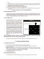
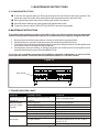
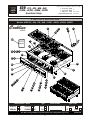
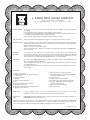
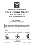
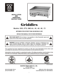
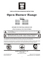
INSTALLATION AND OPERATING INSTRUCTIONS
Open Burner Range
Models:
XOB-212
XOB-424
XOB-636
XOB-848
XOB-212SU
XOB-424SU
XOB-636SU
XOB-848SU
INTENDED FOR OTHER THAN HOUSEHOLD USE
RETAIN THIS MANUAL FOR FUTURE REFERENCE
!
For Your Safety: Do not store or use flammable liquids or vapors in the vicinity of this
or any other appliance.
!
!
Warning: Improper installation, adjustment, alteration, service or maintenance can
cause property damage, injury or death. Read the Installation, Operating and
Maintenance instructions thoroughly before installing or servicing this equipment.
!
This equipment has been engineered to provide you with year round dependable service when used
according to the instructions in this manual and standard commercial kitchen practices.
Instructions must be posted in a prominent location. All safety precautions must be taken in the
event the user smells gas. Safety information can be obtained from your local gas supplier.
S IGN
DE
R
CE
R TIFIED R
CERTIFIED
SANITATION
NSF/ANSI 4
R
P/N U4192A 1/08
BAKERS PRIDE OVEN CO., INC.
30 Pine Street
New Rochelle, NY 10801
(914) 576-0200 Phone
(914) 576-0605 Fax
(800) 431-2745 US & Canada
www.bakerspride.com Web Address
1
IMPORTANT FOR FUTURE REFERENCE
Please complete this information and retain this manual for the life of the equipment. For
Warranty Service and/or Parts, this information is required.
Model Number
Serial Number
Notes:
2
Date Purchased
CONTENTS
1. INSTALLATION INSTRUCTIONS
SECTION
A
B
C
ITEM
Safety Precautions
Unpacking Instructions
Gas Connection
3. MAINTENANCE INSTRUCTIONS
PAGE
SECTION
3
4
4
A
B
C
D
ITEM
PAGE
Cleaning Instructions
Maintenance Instructions
Troubleshooting Chart
Parts List & Exploded View
5
5
5
6
2. LIGHTING INSTRUCTIONS
SECTION
A
B
ITEM
4. WARRANTY
PAGE
Lighting Instructions
Shutdown Instructions
8
4
4
GAS SPECIFICATIONS
Propane Gas
BTU/HR @ 10” W.C.
Model Number
60,000
120,000
180,000
240,000
XOB-212, XOB-212SU
XOB-424, XOB-424S
XOB-636, XOB-636SU
XOB-848, XOB-848SU
Natural Gas
BTU/HR @ 3.5” W.C.
60,000
120,000
180,000
240,000
1. INSTALLATION INSTRUCTIONS
In MASSACHUSETTS: All gas products must be installed by a “Massachusetts” licensed plumber or
gas fitter. Ventilation hoods must be installed in accordance with NFPA-96, current edition, with
interlocks as described in that standard.
A.
SAFETY PRECAUTIONS
FOR YOUR SAFETY, THE FOLLOWING SAFETY PRECAUTIONS SHOULD BE FOLLOWED
AND ENFORCED.
IF YOU SMELL GAS:
SHUT OFF GAS SUPPLY TO APPLIANCE
EXTINGUISH OPEN FLAMES
·
IMMEDIATELY CALL YOUR GAS SUPPLIER
Instructions must be posted in a prominent location. All safety precautions must be taken in the event the
user smells gas. Safety information can be obtained from your local gas supplier.
1. A separate gas shut-off valve must be installed in the gas line ahead of the unit, as required by
codes.
2. LIGHTING: Follow the instructions on page 4.
3. At least 24 inches must be provided at the front of for servicing.
4. When installing, never enclose the bottom area of the unit with a raised curb or other
construction that would obstruct the flow of air into the unit.
5. This unit may be operated with 0” (sides and back) minimum clearance to non-combustible
construction in areas that are non-combustible locations only.
6. This installation must conform to local codes, or in absence of local codes to the National Fuel
Gas Code ANSI Z223.1/NFPA 54, latest edition. In Canada it must conform to current Natural
Gas Installation Code CAN/CGA B 149.1 (natural gas) or CAN/CGA B 149.2 Propane
Installation Code for Gas Burning Appliances & Equipment.
7. The appliance and its individual shut-off valve must be disconnected from the gas supply piping
system during any pressure testing of that system at test pressures in excess of ½ psi (3.45
3
kPa).
8. The appliance must be isolated from the gas supply piping system by closing its individual
manual shut-off valve during any pressure testing of the gas supply piping system at test
pressures equal to or less then ½ psi (3.45 kPa).
9. This appliance must be installed under a ventilation hood.
10. Do not obstruct the flow of combustion and ventilation air.
11. The area around this and any other gas appliance must always be kept free and clear from
combustibles.
RETAIN THIS MANUAL FOR FUTURE REFERENCE.
B. UNPACKING INSTRUCTIONS:
Carefully unpack the open burner range and inspect immediately for shipping damages. Your open
burner range was shipped in a carton designed to give maximum protection in normal handling. It
was thoroughly inspected before leaving the factory and the carrier accepted and signed for it. File
any claims for shipping damage or irregularities with the carrier.
C. GAS CONNECTIONS
A separate gas shut off valve (supplied with
unit) must be installed in the gas line ahead of
the unit, as required by codes (see Fig. A).
Gas supply line must be ¾” or larger. If flexible
semi rigid connections are used, the inside
diameter must be the equivalent of ¾” iron
pipe or larger. All connections of the flexible
and semi rigid type must be AGA listed and
comply with applicable ANSI standards. Make
sure gas piping is clean and free of dirt, piping
compound and obstruction. To insure
maximum operating efficiency, this appliance
must be connected with a Gas Supply Line of
solid pipe or with a Commercial Type Flexible
Connector with I.D. (inside diameter) equal or
larger than the gas pipe inlet on this
appliance.
Figure “A”
MAIN SHUT-OFF VALVE
PRESSURE REGULATOR
STANDING
PILOT
CAUTION: BEFORE LIGHTING, CHECK ALL JOINTS IN THE GAS SUPPLY LINE FOR LEAKS. USE
SOAP AND WATER SOLUTION. DO NOT USE OPEN FLAME.
If the gas connections are leak-free, the unit is ready to use. Follow the lighting instructions.
2. LIGHTING INSTRUCTIONS
A. LIGHTING INSTRUCTIONS
1. Turn off all gas valves and main Shut-off valve and wait 5 minutes.
2. Turn the main gas valve to ON position and light standing pilots adjacent to each main
burner. (FIG. A & B)
3. Repeat the above step for all standing pilots. There should be slight yellow tip on the pilot flame.
Make sure all the pilots are lit. Pilot should be approximately ½”- ¾” in height. Adjust as required
by turning the pilot adjusting screw located on the manifold pipe.
4. Turn the main burner valve to the ON position.
5. To relight follow steps 1-4.
B. SHUTDOWN INSTRUCTIONS
For complete shut down turn all the main burner valves and main gas valve to OFF position.
4
3. MAINTENANCE INSTRUCTIONS
A. CLEANING INSTRUCTIONS
!
!
!
!
Clean the unit regularly after use. Burner ports and burner rest should be thoroughly cleaned. Top
grates are easily removable. After cleaning rinse with clean water and dry with a dry cloth.
Heavy sputtering or spills may require cleaning with a mild oven cleaner.
Use mild soap or detergent to clean chassis and stainless steel parts.
To service burners or pilots TURN OFF GAS SUPPLY and remove top grates.
B. MAINTENANCE INSTRUCTIONS
To provide proper operation and insure the safety of the user, this equipment must be maintained
and serviced by a trained maintenance person or an authorized service agency at regular intervals.
1. Burner ports must be thoroughly cleaned. Venturi must be free from grease and lint.
2. All places where oil, grease or food can accumulate must be kept clean all the time.
3. Pilot light must be kept clean and adjusted at the proper flame height to assure constant ignition and
to prevent fire flash-outs caused by delayed ignition.
4. Carelessness, abusive handling, or altering equipment can shorten the life of the equipment and
jeopardize the limited warranty offered by Baker's Pride.
If you have any questions concerning the installation, operation, maintenance or service of this
product please contact: Technical Service Department at (800) 431-2745 US & Canada
Figure “B”
GAS VALVE
C. TROUBLESHOOTING CHART
PROBLEM
PROBABLE CAUSE
SOLUTION
Burners & pilots will
not turn on
Burners produce
excessive carbon
deposits
Main gas supply to range is not
turned on.
Incorrect gas type.
Incorrect gas supply pressure.
Incorrect orifices.
Primary air not adjusted properly.
Pilot will not remain lit. Pilot flame adjusted incorrectly.
Draft condition.
Burners don't seem
Orifices may be dirty/clogged.
hot enough
Low gas pressure.
Improper ventilation system.
5
Turn on main gas supply.
Supply correct type gas.
Call local gas supplier.
Call Bakers Pride authorized service center.
Adjust air shutter.
Adjust pilot flame.
Remove draft.
When unit cools, check & clean orifices.
Increase gas pressure to 3.5" W.C. (Nat) or
10" W.C. (L.P.)
Call an HVAC specialist.
XOB -212, -424, -636, -848,
30 Pine Street • New Rochelle • New York • 10801
1 - 914 / 576 - 0200
1 - 914 / 576 - 0605 fax
1 - 800 - 431 - 2745 US & Canada
www.bakerspride.com web address
-212SU, -424SU, -636SU, -848SU
Open Burner Range
BAKERS
PRIDE
D. PARTS LIST & EXPLODED VIEW
Models: XOB-212, -424, -636, -848, -212SU, -424SU, -636SU, -848SU
Cookline
41
SERIES
44
Inst/Op
Manual
1
18
17
24
23
22
35
19
16
10 9 8 4
32
37 33
40
BA
KE
RS
B io
XO Vers
rd
da
n
a
(St
PR
ID
E
29
n)
39
2
43
42
31
7
6
5
3
30
34
36
38
20
21
12
13
14
15
25
26
27
28
SUsion)
B
r
XOp Ve
U
ep
(St
Type
Model Number - Width
XOB-212
12”
XOB-636
36”
STD
XOB-424
24”
XOB-848
48”
SU
Page 1 of 2
Type of Gas
Serial Number
Natural
L.P.
Note: When ordering, ALWAYS specify Part #, Model #, Serial #, Voltage/Phase & type of Gas.
6
Other
U6020A 5/07
XOB -212, -424, -636, -848,
BAKERS
PRIDE
Item
P/N
1
G7002K
2
30 Pine Street • New Rochelle • New York • 10801
1 - 914 / 576 - 0200
1 - 914 / 576 - 0605 fax
1 - 800 - 431 - 2745 US & Canada
www.bakerspride.com web address
-212SU, -424SU, -636SU, -848SU
Open Burner Range
Description
Description
Item
P/N
Outer Side, Left
25
R1148P
Manifold Assy, 12"
G7003K
Outer Side, Right
26
R1149P
Manifold Assy, 24"
3
G7010K
Front Panel, 48”
27
R1150P
Manifold Assy, 36"
4
G7011K
Front Trim, 48"
28
R1151P
Manifold Assy, 48"
5
G7018K
Front Panel, 12"
29
R3020A
Valve, Pilot-Dual, 1/8-27 x 3/16"
6
G7019K
Front Panel, 24"
30
R3023A
Orifice, Blank
7
G7020K
Front Panel, 36"
24
N5880P
Pilot (SU, Rear) Not Shown
8
G7026K
Front Trim, 12"
31
R3032A
Valve, LML-15 1/8-27 X 3/8-27 Hood
9
G7027K
Front Trim, 24"
32
R3203A
Front Venturi
10
G7028K
Front Trim, 36"
33
R3204A
Venturi, Rear, Std
11
G7046K
Pilot Clip (Not Shown)
34
R3205A
Orifice #38, Nat Gas
12
G7051K
Crumb Tray, 48"
35
R3206A
Valve, Gas Shut-Off
13
G7052K
Crumb Tray, 36"
36
R3222P
Orifice #52, LP Gas
14
G7053K
Crumb Tray, 24"
37
R3249A
Venturi, Rear, Step-Up
15
G7054K
Crumb Tray, 12"
38
R3250P
Orifice #53, But/Prop Gas
16
L5105A
Burner, Open Top Burner (CI)
39
S1395A
Leg, 6"
17
M1009A
Pressure Regulator, 3/4",10.0 WC, LP
40
S1416A
Knob, Gas Valve, On-Off
18
M1184A
Pressure Regulator, 3/4", 3.5 WC, Nat
41
T1247A
Grate, 12' x 13", Cast Iron
19
M1460A
Pilot Burner, Nat Gas
42
U1044X
Name-Plate, Bakers Pride Logo 8"(Small)
20
N3023A
Plug, 1/8" Brass
43
U1381A
Label, Lighting Instruction
21
N3068P
Pressure Tap Nozzle Assy
44
U4192A
Inst/Op Manual
22
N5856P
Pilot Tubing, S/S, 3/16" (Standard & SU, Front)
45
X1019A
Carton (12" & 24" Units) Not Shown
23
N5857P
Pilot Tubing, S/S, 3/16" (Standard & Rear)
46
X1046A
Carton (36" & 48" Units) Not Shown
HARDWARE (NOT SHOWN)
Item
P/N
N/S
Description
Description
Item
Q1406A
Screw, #10 x 1/2", Truss Hd, Slot
N/S Q1502A
Screw, #10 x 1", Pan Hd, Php
N/S
Q1407A
Screw, #10 x 1/2", Hex Hd, Slot
N/S Q2002A
Screw, 1/4-20 x 1/2", Truss Hd, Slot
N/S
Q1445A
Screw, 10 x 3/4", Hex Hd w/Washer
N/S Q2046A
Nut, 1/4-20, Hex, Lock
N/S
Q1472A
Screw, 1/4-20 x 1/4",Button Hd S/S
N/S Q2335A
Nut, 3/4-10, Hex, Heavy
N/S
Q1475A
Screw, 10-32 x 1/2",Truss Hd S/S
N/S Q3044A
Washer, .437 0.260 I.D,.062 Thk Flat
N/S
Q1478A
Nut, 10-32,Hex Hd, Lock
Page 2 of 2
P/N
N/S = Not Shown
Note: When ordering, ALWAYS specify Part #, Model #, Serial #, Voltage/Phase & type of Gas.
7
U6020A 5/07
4. BAKERS PRIDE LIMITED WARRANTY
30 Pine Street New Rochelle, New York 10801
914 / 576 - 0200 ♦ US & Canada: 1 - 800 - 431 - 2745 ♦ fax 914 / 576 - 0605
WHAT IS COVERED
This warranty covers defects in material and workmanship under normal use, and applies only to the original purchaser
providing that:
♦ The equipment has not been accidentally or intentionally damaged, altered or misused;
♦ The equipment is properly installed, adjusted, operated and maintained in accordance with National and local codes. and
in accordance with the installation instruction provided with the product;
♦ The serial number rating plate affixed to the equipment has not been defaced or removed.
WHO IS COVERED
This warranty is extended to the original purchaser and applies only to equipment purchased for use in the U.S.A.
COVERAGE PERIOD
Full size gas and electric deck ovens: Two (2) year limited parts and labor: Cyclone Convection Ovens: BCO Models: One (1)
Year limited parts and labor; GDCO Models: Two (2) Year limited parts and labor; CO II Models: Two (2) Year limited parts
and labor; (5) Year limited door warranty.
All Other Products: One (1) Year limited parts and labor.
Warranty period begins the date of dealer invoice to customer or ninety (90) days after shipment date from BAKERS PRIDE whichever comes first.
WARRANTY
COVERAGE
This warranty covers on-site labor, parts and reasonable travel time and travel expenses of the authorized service
representative up to (100) miles. round trip, and (2) hours travel time. The purchaser. however, shall be responsible for all
expenses related to travel, including time. mileage and shipping expenses on smaller counter models that may be carried into
a Factory Authorized Service Center, including the following models: PX-14. PX-16, PI8, and BK-I8.
EXCEPTIONS
All removable parts in BAKERS PRIDE Char-broilers, including but not limited to: Burners, Grates. Radiants, Stones and
Valves, are covered for a period of SIX MONTHS.
All Ceramic Baking Decks are covered for a period of THREE MONTHS. The installation of these replacement decks is the
responsibility of the purchaser.
The extended Cyclone door warranty years 3 through 5 is a parts only warranty and does not include labor, travel, milage or
any other charges.
EXCLUSIONS
♦ Failures caused by erratic voltages or gas supplies,
♦ Unauthorized repair by anyone other than a BAKERS PRIDE
Factory Authorized Service Center,
♦ Damage in shipment,
♦ Alteration, misuse or improper installation,
♦ Thermostats and safety valves with broken capillary tubes.
♦ Accessories - spatulas, forks. steak turners, grate lifters,
oven brushes, scrapers, peels. etc.,
♦ Freight - other than normal UPS charges,
♦ Ordinary wear and tear.
♦ Negligence or acts of God,
♦ Thermostat calibrations after (30) days from equipment
installation date,
♦ Air and Gas adjustments,
♦ Light bulbs,
♦ Glass doors and door adjustments.
♦ Fuses,
♦ Char-broiler work decks and cutting boards,
♦ Tightening of conveyor chains,
♦ Adjustments to burner flames and cleaning of pilot burners,
♦ Tightening of screws or fasteners.
INSTALLATION
Leveling and installation of decks. as well as proper installation and check out of all new equipment - per appropriate
installation and use materials - is the responsibility of the dealer or installer, not the manufacturer.
REPLACEMENT
PARTS
BAKERS PRIDE genuine Factory OEM parts receive a (90) day materials warranty effective from the date of installation by a
BAKERS PRIDE Factory Authorized Service Center.
This Warranty is in lieu of all other warranties, expressed or implied, and all other obligations or liabilities on the manufacturers part. BAKERS PRIDE
shall in no event be liable for any special, indirect or consequential damages, or in any event for damages in excess of the purchase price of the unit. The
repair or replacement of proven defective parts shall constitute a fulfillment of all obligations under the terms of this warranty.
Form #U4177A 1/07
8