1
SPECIAL MESSAGE SECTION
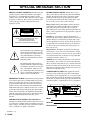
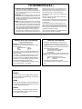
PRODUCT SAFETY MARKINGS: Yamaha electronic
products may have either labels similar to the graphics
shown below or molded/stamped facsimiles of these
graphics on the enclosure. The explanation of these graphics appears on this page. Please observe all cautions indicated on this page and those indicated in the safety
instruction section.
CAUTION
RISK OF ELECTRIC SHOCK
DO NOT OPEN
CAUTION: TO REDUCE THE RISK OF ELECTRIC SHOCK.
DO NOT REMOVE COVER (OR BACK).
NO USER-SERVICEABLE PARTS INSIDE.
REFER SERVICING TO QUALIFIED SERVICE PERSONNEL.
The exclamation point within the equilateral triangle is intended to alert the
user to the presence of important operating and maintenance (servicing)
instructions in the literature accompanying the product.
The lightning flash with arrowhead
symbol, within the equilateral triangle,
is intended to alert the user to the presence of uninsulated “dangerous voltage” within the product’s enclosure that
may be of sufficient magnitude to constitute a risk of electrical shock.
IMPORTANT NOTICE: All Yamaha electronic products
are tested and approved by an independent safety testing
laboratory in order that you may be sure that when it is
properly installed and used in its normal and customary
manner, all foreseeable risks have been eliminated. DO
NOT modify this unit or commission others to do so unless
specifically authorized by Yamaha. Product performance
and/or safety standards may be diminished. Claims filed
under the expressed warranty may be denied if the unit is/
has been modified. Implied warranties may also be
affected.
SPECIFICATIONS SUBJECT TO CHANGE: The
information contained in this manual is believed to be correct at the time of printing. However, Yamaha reserves the
right to change or modify any of the specifications without
notice or obligation to update existing units.
92-469- ➀ (rear)
2
RS7000
ENVIRONMENTAL ISSUES: Yamaha strives to produce products that are both user safe and environmentally
friendly. We sincerely believe that our products and the
production methods used to produce them, meet these
goals. In keeping with both the letter and the spirit of the
law, we want you to be aware of the following:
Battery Notice: This product MAY contain a small nonrechargable battery which (if applicable) is soldered in
place. The average life span of this type of battery is
approximately five years. When replacement becomes necessary, contact a qualified service representative to perform
the replacement.
Warning: Do not attempt to recharge, disassemble, or
incinerate this type of battery. Keep all batteries away from
children. Dispose of used batteries promptly and as regulated by applicable laws. Note: In some areas, the servicer
is required by law to return the defective parts. However,
you do have the option of having the servicer dispose of
these parts for you.
Disposal Notice: Should this product become damaged
beyond repair, or for some reason its useful life is considered to be at an end, please observe all local, state, and federal regulations that relate to the disposal of products that
contain lead, batteries, plastics, etc.
NOTICE: Service charges incurred due to lack of knowledge relating to how a function or effect works (when the
unit is operating as designed) are not covered by the manufacturer’s warranty, and are therefore the owners responsibility. Please study this manual carefully and consult your
dealer before requesting service.
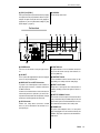
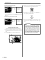
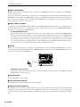
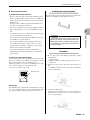
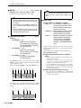
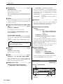
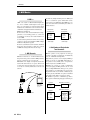
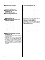
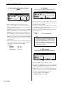
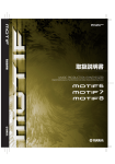
NAME PLATE LOCATION: The graphic below indicates the location of the name plate. The model number,
serial number, power requirements, etc., are located on this
plate. You should record the model number, serial number,
and the date of purchase in the spaces provided below and
retain this manual as a permanent record of your purchase.
THIS CLASS B DIGITAL APPARATUS COMPLIES WITH CANADIAN ICES-003.
MUSICAL INSTRUMENT
379U
CET APPAREIL NUMÉRIQUE DE LA CLASSE B EST CONFORME À LA NORME NMB-003
DU CANADA.
MIDI
US LISTED
THIS DEVICE COMPLIES WITH PART 15 OF THE FCC RULES. OPERATION IS SUBJECT TO THE
FOLLWWING TWO CONDITIONS:
(1)THIS DEVICE MAY NOT CAUSE HARMFUL INTERFERENCE,AND
(2)THIS DEVICE MUST ACCEPT ANY INTERFERENCE RECIVED,INCLUDING INTERFERENCE
THAT MAY CAUSE UNDESIRED OPERATION.
IN
INPUT
CAUTION
POWER
ON/ OFF
SCSI
RISK OF ELECTRIC SHOCK
DO NOT OPEN
ATTENTION : RISQUE DE CHOC ÉLECTRIQUE NE PAS OUVRIR.
TO REDUCE THE RISK OF FIRE OR ELECTRIC SHOCK,
WARNING DO
NOT EXPOSE THIS PRODUCT TO RAIN OR MOISTURE.
FOOT SW
CONTRAST
R
L
R
OUTPUT
L/MONO
PHONES
OUT A
AC INLET
OUT B
Rear Panel
Model
Serial No.
Purchase Date
PRECAUTIONS
PLEASE READ CAREFULLY BEFORE PROCEEDING
* Please keep this manual in a safe place for future reference.
WARNING
Always follow the basic precautions listed below to avoid the possibility of serious injury or even death from
electrical shock, short-circuiting, damages, fire or other hazards. These precautions include, but are not limited
to, the following:
Power supply/Power cord
Water warning
• Only use the voltage specified as correct for the instrument. The required
voltage is printed on the name plate of the instrument.
• Check the electric plug periodically and remove any dirt or dust which may
have accumulated on it.
• Do not expose the instrument to rain, use it near water or in damp or wet
conditions, or place containers on it containing liquids which might spill into
any openings.
• Never insert or remove an electric plug with wet hands.
• Use only the supplied power cord/plug.
• Do not place the power cord near heat sources such as heaters or radiators,
and do not excessively bend or otherwise damage the cord, place heavy
objects on it, or place it in a position where anyone could walk on, trip over,
or roll anything over it.
Fire warning
• Do not put burning items, such as candles, on the unit.
A burning item may fall over and cause a fire.
If you notice any abnormality
Do not open
• If the power cord or plug becomes frayed or damaged, or if there is a sudden
loss of sound during use of the instrument, or if any unusual smells or
smoke should appear to be caused by it, immediately turn off the power
switch, disconnect the electric plug from the outlet, and have the instrument
inspected by qualified Yamaha service personnel.
• This instrument contains no user-serviceable parts. Do not attempt to
disassemble or modify the internal components in any way.
CAUTION
Always follow the basic precautions listed below to avoid the possibility of physical injury to you or others, or
damage to the instrument or other property. These precautions include, but are not limited to, the following:
Power supply/Power cord
Location
• Always connect the three-pin attachment plug to a properly grounded power
source. (For more information about the main power supply, see page 22.)
• When removing the electric plug from the instrument or an outlet, always
hold the plug itself and not the cord. Pulling by the cord can damage it.
• Do not expose the instrument to excessive dust or vibrations, or extreme cold
or heat (such as in direct sunlight, near a heater, or in a car during the day) to
prevent the possibility of panel disfiguration or damage to the internal
components.
• Do not use the instrument in the vicinity of a TV, radio, stereo equipment,
mobile phone, or other electric devices. Otherwise, the instrument, TV, or
radio may generate noise.
• Remove the electric plug from the outlet when the instrument is not to be
used for extended periods of time, or during electrical storms.
• Do not connect the instrument to an electrical outlet using a multipleconnector. Doing so can result in lower sound quality, or possibly cause
overheating in the outlet.
• Do not place the instrument in an unstable position where it might
accidentally fall over.
• Before moving the instrument, remove all connected cables.
(2)-8
1/2
RS7000 3
Connections
Backup battery
• Before connecting the instrument to other electronic components, turn off the
power for all components. Before turning the power on or off for all
components, set all volume levels to minimum. Also, be sure to set the
volumes of all components at their minimum levels and gradually raise the
volume controls while playing the instrument to set the desired listening
level.
• This instrument has a built-in lithium backup battery. When you unplug the
power cord from the AC outlet, the system setup data (Utilitey mode [Page
255] and other settings) is retained. However, if the backup battery fully
discharges, this data will be lost. When the backup battery is running low, the
display indicates “Backup Battery Low.” In this case, immediately save the
data to a Memory Card (SmartMedia)/a SCSI disk (See page 114, 166, 204),
then have qualified Yamaha service personnel replace the backup battery.
Maintenance
• When cleaning the instrument, use a soft, dry cloth. Do not use paint
thinners, solvents, cleaning fluids, or chemical-impregnated wiping cloths.
Saving data
Saving and backing up your data
• Voice and sequence data you created is lost when you turn off the power to
the instrument. Save the data to a Memory Card (SmartMedia)/a SCSI disk
(See page 114, 166, 204) .
Handling caution
• Do not insert a finger or hand in any gaps on the instrument.
• Never insert or drop paper, metallic, or other objects into the gaps on the
panel. If this happens, turn off the power immediately and unplug the power
cord from the AC outlet. Then have the instrument inspected by qualified
Yamaha service personnel.
• System setup data (Utility mode [Page 255] and other settings) is retained
when the power is turned off, as long as the backup battery retains a charge.
However, the data could be lost due to malfunction or incorrect operation.
Save important data to a Memory Card (SmartMedia)/a SCSI disk.
• Do not place vinyl, plastic or rubber objects on the instrument, since this
might discolor the panel or keyboard.
Backing up the Memory Card (SmartMedia)/SCSI disk
• Do not rest your weight on, or place heavy objects on the instrument, and do
not use excessive force on the buttons, switches or connectors.
• To protect against data loss through media damage, we recommend that you
save your important data onto two Memory Cards (SmartMedia)/SCSI disks.
• Do not operate the instrument for a long period of time at a high or
uncomfortable volume level, since this can cause permanent hearing loss. If
you experience any hearing loss or ringing in the ears, consult a physician.
Yamaha cannot be held responsible for damage caused by improper use or modifications to the instrument, or data that is lost or destroyed.
Always turn the power off when the instrument is not in use.
Make sure to discard used batteries according to local regulations.
4
RS7000
(2)-8
2/2
Handling and Installation of Options
WARNING
• Before beginning installation, switch off the power to the RS7000 and connected peripherals, and unplug them
from the power outlet. Then remove all cables connecting the RS7000 to other devices. (Leaving the power cord
connected while working can result in electric shock. Leaving other cables connected can interfere with work.)
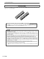
• Do not disassemble, modify, or apply excessive force to board areas and connectors on the option board and
SIMMs. Bending or tampering with boards and connectors may lead to electric shock, fire, or equipment
failures.
CAUTION
• Before handling an option board or SIMM, you should briefly touch the RS7000 metal casing (or other such
metallic area) with your bare hand so as to drain off any static charge from your body. Note that even a slight
amount of electrostatic discharge may cause damage to these components.
• It is recommended that you wear gloves to protect your hands from metallic projections on the RS7000, SIMMs,
an option board, and other components. Touching leads or connectors with bare hands may cause finger cuts,
and may also result in poor electrical contact or electrostatic damage.
• Take care to avoid dropping screws into the RS7000 unit. If a screw does fall in, be sure to remove it before you
reassemble and power up the unit. Starting the unit with a loose screw inside may lead to improper operation or
equipment failure. (If you are unable to retrieve a dropped screw, consult your Yamaha dealer for advice.)
*
*
Consult your Yamaha dealer if you have any questions regarding installation procedures for the option board or SIMMs.
If SIMM memory fails to work properly, consult the item's dealer for advice.
RS7000 5
Supplied Accessories
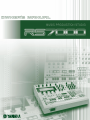
I N T R O D U C T I O N
Thank you for your purchase of the Yamaha MUSIC PRODUCTION STUDIO RS7000.
The Yamaha R7000 brings it all together. Everything you need for professional-level music and
remix production — particularly in dance, techno, hip hop, R&B, and ambient genres — is
included and flawlessly integrated in a system that has been specifically designed to facilitate
modern production techniques. The RS7000 combines a powerful, flexible sequencing system
with a state-of-the-art AWM2 tone generator loaded with an awesome selection of drum kits
and voices, and a sampler which allows you to sample your own sounds and loops and easily
incorporate them into your sequences. All of this is brought together with an interface that is
intuitive and easy while offering the depth and real-time control required by professional
applications.
In order to take maximum advantage of the many advanced features and capabilities offered
by the RS7000, we urge you to read the manual carefully, and keep it in a safe, readily-accessible location for future reference.
* The company names and product names in this Owner’s Manual are the trademarks or registered trademarks of their respective companies.
* Unauthorized copying of copyrighted software for purposes other than purchaser’s personal use is prohibited.
Supplied Accessories
Please check that the following accessories are included in the RS7000 package.
• CD-ROM × 1
• Memory Card × 1
• AC Power Cord × 1
• Memory Card Security Adapter × 1
• Owner’s Manual (this document) × 1
• “About the Memory Card & CD-ROM” Document × 1
• AC Power Cord
• Memory Card Security Adapter
* Refer to the separate “About the Memory Card & CD-ROM” document for information about the contents of the supplied Memory
Card and CD-ROM.
6
RS7000
RS7000 FEATURES
RS7000 FEATURES
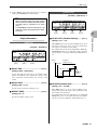
● Powerful 16-track Sequencer
In the phrase-based PATTERN mode, complete patterns can be quickly assembled by combining individual phrases from the vast range of preset phrases provided, or you can record your own using the
extensive selection of drum kits and other voices provided by the internal AWM2 tone generator. Sampled sounds, loops and breakbeats can just as easily be added to the sequence to create the groove
your music demands. Your patterns can be used individually, or the PATTERN CHAIN mode can be
used to automatically sequence specified patterns to create even complex arrangements.
There’s also a SONG mode which functions as a 16-track sequencer with all the features and versatility you’d expect from a full-blown stand-alone sequencer … and more.
● AWM2 Tone Generator
Even electronic sounds change with the times, and the RS7000 is right up to date. The internal AWM2
tone generator system offers more than 1054 pitched voices, and sound effects, as well as 63 top-quality
drum kits — you’ll find what you need for just about any musical genre. You also have a range of voice
editing functions that make it easy to customize and personalize the sound to bring your art to life.
● A Wealth of Preset Phrases
Up-to-date preset phrases are provided. Patch these together in the PATTERN mode for an unlimited
range of pattern variations.
● Arpeggio Function
5 auto-arpeggio types are ideal for use in dance and techno styles. Arpeggiated phrases can be
recorded to the sequencer and edited as required, or transmitted to other gear via MIDI.
● Advanced Sampling and Editing Features
In addition to directly loading sample data in a variety of popular formats, the RS7000 allows you to
record your own samples from CDs or any line-level or microphone source. Once your samples are
recorded they can be trimmed, sliced, looped, and otherwise prepared for playback with the power
and flexibility you’d expect from a stand-alone sampler. And when your samples are ready, they can be
incorporated into patterns and sequences just as easily as the tone-generator voices. You can even
use the sampler to record vocal parts to take your project right up to the final production stage without
using any equipment other than the RS7000.
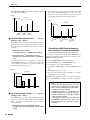
● Real-time Loop Remix and Play Effects
Performance data can be automatically divided and randomly rearranged to create totally new sounds.
Create a range of variations instantly from a drum pattern, for example.
Play effects are also ideal for real-time creative variation, allowing you to tweak timing, note parameters, or harmonization without altering the sequence data.
● Real-time Control
Another key requirement for creative freedom in modern music production is real-time sound control.
The RS7000 offers plenty of sonic manipulation capability with a comprehensive range of knobs for
hands-on control of BPM, filter parameters, envelopes, pitch, LFO, and more. The RS7000 also features a keyboard and velocity-sensitive pads that allow voices and samples to be played in real time,
as well as switching between sequence sections and tracks, and controlling the track mute and solo
functions. The RS7000 also features mute and scene memory functions which can take “snapshots” of
track mute setups or complete panel-control setups that can be recalled in an instant.
RS7000 7
Using the Owner’s Manual
● Memory Card Storage, SCSI, and Memory Expansion
Sequences, phrases, and samples can be conveniently stored on compact, high-capacity memory
cards, or on just about any type of external SCSI storage medium (hard disk, MO, ZIP, etc.) connected
to the RS7000’s SCSI port. You can also connect read-only devices such as a CD-ROM drive to conveniently load samples and other data. 2 SIMM slots are provided for memory expansion, allowing the
RES7000 to be packed with up to 64 megabytes of RAM for extra sampling leeway.
● I/O Expansion
The optional AEB1 I/O expansion board can be installed in the RS7000 to provide 6 additional individual analog outputs as well as both coaxial and optical digital input and output.
● An Extensive Range of Effects
In today’s music effects are almost as important as the sounds they are applied to. The RS7000 offers
plenty of sound processing power with PLAY FX which function at the sequencing stage to provide
harmonization as well as note and timing variations; a three-stage DSP effect system with VARIATION, DELAY, and REVERB effects; and a MASTER EFFECT stage that offers a range of up-to-date
effects for the overall sound.
● In Depth Jobs and Editing
Creating sequences that sound just right can be a tricky business, but the RS7000 makes the job as
smooth and easy as possible with an extensive selection of jobs and editing functions. There’s grid
groove, for example, to give your tracks the kind of groove and feel that straightforward sequencing
simply can’t achieve. In the RS7000 this flexible feature works with samples as well as tone-generator
data for unprecedented “feel” control. Another sampling feature that offers hands-on creative control is
“real time loop remix” — a powerful and easy way to remix your sampled loops while monitoring them
in real time. Then there are jobs to automatically create glides, rolls, crescendos, and other subtleties
that can make a huge difference to the musical mood. If you can image it, the RS7000 can probably do
it. And when you want to really make detailed refinements, the EDIT mode gives you direct access to
individual note and even parameters.
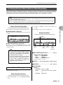
Using the Owner’s Manual
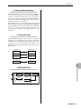
The Manual Structure
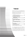
The RS7000 Owner’s Manual is broadly divided into 3 main sections: the Tutorial section, the Reference section, and the Appendix.
● The Tutorial Section
This section covers basics such as the structure of the RS7000 system, voice selection, recording, sampling, and other
operations that are fundamental to the RS7000.
● The Reference Section
This section includes detailed descriptions and procedures for all of the RS7000 features and functions. Use it as an
“encyclopedia of functions” to find specific information you need.
The Reference section includes the following chapters:
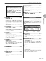
Chapter 1: Basics...(Page 51)
The basic concepts, procedures, displays, and special functions you’ll need to know in order to operate the RS7000 efficiently. Be sure to read this chapter before using the RS7000 for the first time.
Chapter 2: The Pattern Mode ...(Page 69) ~ Chapter 6: The Utility Mode...(Page 255)
Complete, detailed coverage of all features and functions, organized by mode. Find specific information about specific
functions in these chapters.
Chapter 7: Other Information...(Page 263)
Basic information about MIDI and MIDI events handled by the RS7000. Refer to this chapter form information about
using the RS7000 with other MIDI devices.
Appendix...(Page 271)
Information on installing optional equipment, the RS7000 specifications, voice lists, effect list, error messages, MIDI data
format, and other detailed information.
8
RS7000
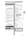
Finding Specific Information
Finding Specific Information
Use one of the methods described below to find the information you are looking for.
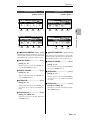
● The Table of Contents ...(Page 10)
The Table of Contents is best for finding chapters or sections of the manual that cover the type of information you are
looking for.
● The Index ...(Page 343)
The index is the place to look when you are searching for a specific function or information related to specific nomenclature.
● The Controls & Connectors ...(Page 12)
This section provides information about the RS7000 panel controls and connectors, with references to related information throughout the manual.
● The Function Tree ...(Page 55)
The Function Tree lists all RS7000 functions with page references in a tree-type diagram which is organized by mode.
● The Page Footers, Margins, and Headers
The area at the bottom of each page shows the page number. The chapter numbers and titles are also listed in the rightmost margin of each spread. The header (the top margin) displays the title of the information included in the page. This
information can help you find information while flipping through the manual pages.
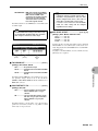
Symbols
The following symbols are used through the manual to indicate different types of information.
IMPORTANT .................. Important information! Read this to ensure that you don’t accidentally erase important
data or make other potentially serious errors.
NOTE
................................. Incidental information. This information is helpful, through not always essential. Read
as necessary.
[Step] ..................................... Procedure. Step-by-step instructions for performing an operation.
[PLAY] .................................... Buttons. References to the RS7000 buttons will appear like this in the text.
P
** ..................................... Page reference. Related information can be found on the page number provided.
The illustrations and LCD screens as shown in this owner’s manual are for instructional purposes only, and may appear somewhat different from those on your instrument.
RS7000 9
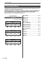
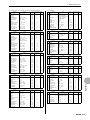
CONTENTS
CONTENTS
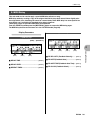
RS7000 FEATURES ....................................................... 7
Using the Owner’s Manual ............................................ 8
Finding Specific Information ........................................ 9
Symbols .......................................................................... 9
CONTENTS ................................................................... 10
The Controls & Connectors ........................................ 12
Notes on Musical Copyright ....................................... 21
Preparation and Setup ................................................ 22
Power Connection ..................................... 22
Connecting to Audio Equipment ................ 22
Connecting a Footswitch ........................... 23
Connecting External MIDI Devices ............ 23
Turning Power On and Off......................... 24
Restoring the Initial Factory Settings ........................ 25
Tutorial
1.
2.
3.
4.
5.
6.
RS7000 System Overview..................................... 28
Assemble a Pattern Using Preset Phrases ......... 30
Real-time Sound Control ...................................... 38
Recording Original Phrases ................................. 39
Add Samples.......................................................... 43
Finalizing Your Sound .......................................... 46
Reference
Character Entry ......................................... 67
Track Selection.......................................... 67
Free Tempo Entry...................................... 68
Used Memory Display ............................... 68
Initializes the Master Effect settings .......... 68
Undo/Redo ................................................ 68
Auto Repeat............................................... 68
Auto Load .................................................. 68
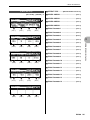
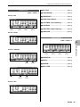
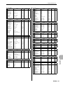
Chapter 2. The Pattern Mode
About the Pattern Mode .............................................. 70
1. Pattern Playback ................................................... 72
2. Combining Phrases to Create Patterns (Patch) .... 75
3. Phrase Recording ................................................. 77
Record Standby................................................... 78
Real-Time Recording........................................... 80
Step Recording.................................................... 80
Grid Step Recording ............................................ 83
4. Adding Groove to a Pattern ................................. 85
5. Play Effects............................................................ 87
6. MIDI Delay .............................................................. 90
7. Adjusting Level and Effects for
Each Track (Mixer) ................................................ 93
8. Changing the Sound of Voices (Voice Edit) ....... 97
9. Adding Effects..................................................... 104
10. Arpeggio & Assignable Knob Settings (Setup)... 107
11. Master EQ and Effects ........................................ 111
12. Saving to Memory Card or Disk......................... 114
13. Loading From Memory Card or Disk ................. 126
14. Pattern & Phrase Editing — The Pattern Jobs .... 133
15. Phrase Editing ..................................................... 154
Chapter 3. The Pattern Chain Mode
Chapter 1. Basic
51
1. RS7000 System Overview..................................... 52
Mode Structure .................................................... 52
Function Tree....................................................... 55
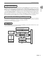
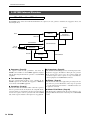
2. RS7000 Internal Structure .................................... 58
The 6 Functional Blocks ...................................... 58
Sequencer ................................................. 59
Tone Generator ......................................... 60
Controllers ................................................. 62
Arpeggiator ................................................ 63
Effects........................................................ 63
Master EQ & Effects .................................. 63
Memory Configuration ............................... 63
3. Basic Operation..................................................... 64
Selecting Modes ........................................ 64
Selecting Sub Modes................................. 64
When One Button Accesses
Several Pages ........................................... 65
Editing Parameter Values .......................... 66
Command Selection and Execution........... 66
Job Selection ............................................. 67
10 RS7000
69
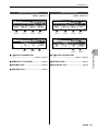
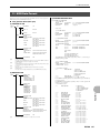
157
About the Pattern Chain Mode ................................. 158
1. Sequential Pattern Playback
(Pattern Chain Play) ............................................ 159
2. Creating Pattern Chains
(Pattern Chain Recording).................................. 161
Record Standby................................................. 161
Real Time Recording......................................... 162
Step Recording.................................................. 163
3. Master EQ and Effects ........................................ 164
4. Saving to Memory Card or Disk......................... 166
5. Loading from Memory Card or Disk .................. 169
6. The Pattern Chain Jobs ...................................... 171
7. Pattern Chain Editing.......................................... 175
Chapter 4. The Song Mode
179
About the Song Mode ............................................... 180
1. Song Playback..................................................... 182
2. Song Recording .................................................. 184
Record Standby................................................. 184
CONTENTS
3.
4.
5.
6.
7.
8.
9.
10.
11.
12.
13.
14.
Real-Time Recording......................................... 186
Step Recording .................................................. 187
Grid Step Recording .......................................... 189
Adding Groove to a Pattern................................ 191
Play Effects .......................................................... 192
MIDI Delay ............................................................ 193
Adjusting Level and Effects for
Each Track (Mixer) .............................................. 194
Changing the Sound of Voices (Voice Edit) ..... 196
Adding Effects ..................................................... 198
Arpeggio & Assignable Knob Settings (Setup) ... 200
Master EQ and Effects ........................................ 202
Saving to Memory Card or Disk ......................... 204
Loading from Memory Card or Disk .................. 208
The Song Jobs..................................................... 212
Song Editing ........................................................ 225
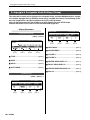
Chapter 5. The Sampling Mode
227
About the Sampling Mode ........................................ 228
1. Recording Samples (Sampling) ......................... 229
2. The Real Time Loop Remix Function ................ 239
3. Sample Editing .................................................... 241
4. The Sample Jobs................................................. 244
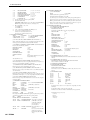
Chapter 6. The Utility Mode
255
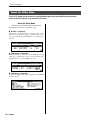
About the Utility Mode............................................... 256
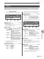
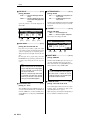
1. System.................................................................. 257
2. MIDI Setup............................................................ 260
3. MIDI Filter ............................................................. 262
Chapter 7. Other Information
263
1. MIDI Basics .......................................................... 264
2. MIDI Events Handled by the RS7000 ................. 266
Appendix
1.
2.
3.
4.
5.
6.
7.
8.
9.
10.
11.
12.
13.
271
Installing Optional Equipment ........................... 272
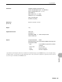
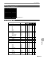
Specifications ...................................................... 282
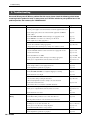
Troubleshooting .................................................. 286
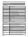
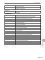
Error Message List .............................................. 288
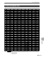
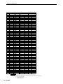
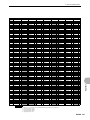
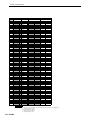
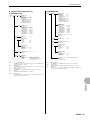
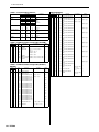
Voice List (Normal voice) ................................... 291
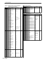
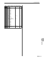
Drum Voice List ................................................... 295
Phrase Category List .......................................... 313
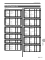
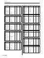
Effect Type List.................................................... 313
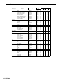
Effect Parameter List .......................................... 315
Effect Data/Value table........................................ 323
MIDI Data Format................................................. 325
Glossary ............................................................... 334
Index ..................................................................... 343
RS7000 11
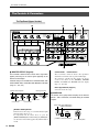
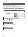
The Controls & Connectors
The Controls & Connectors
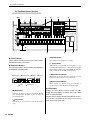
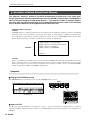
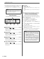
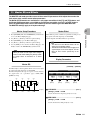
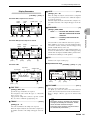
The Top Panel (Upper Section)
1
2
3
4
MUSIC PRODUCTION STUDIO
Integrated Sampling Sequencer
MASTER EFFECT
SAMPLING
MULTI COMP
CTRL DELAY
D-FILTER
ISOLATION
EFFECT
ON/OFF
RING MOD
V-DIST
LO-FI
SLICE
REAL TIME
LOOP
REMIX
SAMPLE
EDIT
IN
STANDBY
OUT A
OUT B
START/STOP
REC VOLUME
MIDI
MASTER VOLUME
EFFECT SEND / VOLUME
SEQUENCE PLAY FX
SELECT
8
5
9
BEAT STRETCH CLOCK SHIFT
GATE TIME
MIDI DELAY
SWING
VELOCITY
DRY
VARI
DELAY/CHO
REVERB
TRACK VOLUME
DECAY
SUSTAIN
RELEASE
EG
LFO
WAVE
0
SPEED
USER
S&H
PGM
A
AMP
FILTER
PITCH
DEPTH
ATTACK
FILTER
PITCH
C
6
+
-
PORTAMENTO
TYPE
FINGERED
TYPE
OFF
PITCH BEND
F1
F2
F3
LPF24
LPF18
LPF12
HPF
D
FULL TIME
PORTAMENTO TIME
CUTOFF
RESONANCE
ENV.DEPTH
BPF
BEF
F4
7
MODE
PATTERN
NUM
PATT
CHAIN
SONG
UTILITY
UTILITY
SYSTEM
MIDI SETUP
MIDI FILTER
B
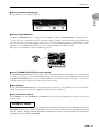
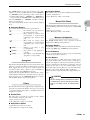
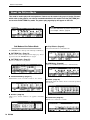
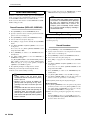
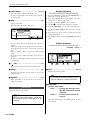
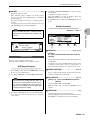
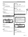
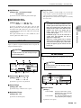
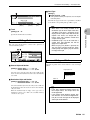
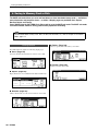
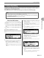
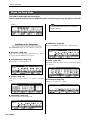
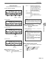
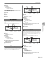
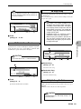
1 MASTER EFFECT (Page 63)
These controls control the final master effect stage which
applies processing to the stereo signal appearing at the
RS7000 stereo outputs.
Detailed settings are available in the PATTERN mode, PATTERN CHAIN mode, and SONG mode MASTER sub mode
(Page 111, 164, 202).
Control Knob 1 ~ Control Knob 4
These four knobs control the master effect parameters
shown below each knob at the top of the LCD display.
The parameters controlled by these knobs can also be
accessed and edited via the PATTERN, PATTERN
PATCH, and SONG mode MASTER sub mode display
(Page 111, 164, 202).
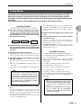
Effect Type Selector (Page 63)
Effect Type Selector
[EFFECT ON/OFF] Button
MASTER EFFECT
EFFECT
ON/OFF
MULTI COMP
CTRL DELAY
D-FILTER
ISOLATION
RING MOD
V-DIST
LO-FI
SLICE
Control Knob 4
Control Knob 2
Control Knob 1
Control Knob 3
Selects the master effect type.
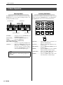
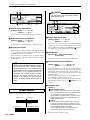
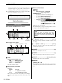
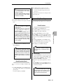
2 SAMPLING
The controls in this group control sampling via the RS7000
INPUT L and R connectors, and allow editing of recorded
samples.
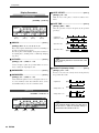
[REAL TIME LOOP REMIX] Button
[SAMPLE EDIT] Button
SAMPLING
[EFFECT ON/OFF] Button
REAL TIME
Turns the master effect stage on or off. The indicator lights
when the master effects are on.
To temporarily turn the master effect on, press the
[EFFECT ON/OFF] button while holding the [SHIFT] button. The master effect will be applied only while the button
is held.
12 RS7000
LOOP
REMIX
SAMPLE
EDIT
STANDBY
START/STOP
[STANDBY START/STOP] Button
REC VOLUME
[REC VOLUME] Knob
The Controls & Connectors
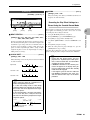
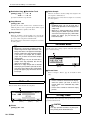
[REAL TIME LOOP REMIX] Button (Page 239)
Turns the real-time loop remix function on or off. The
indicator lights when the real-time remix feature is on.
[SAMPLE EDIT] Button (Page 241)
Engages the SAMPLE EDIT mode. The indicator lights
when the SAMPLE EDIT mode is active.
[STANDBY START/STOP] Button (Page 229)
Switches to the sampling mode, and starts/stops the sampling operation.
[REC VOLUME] Control
Adjusts the input level of the analog signal appearing at
the INPUT L and R connectors. Used for sample recording
and A/D input.
When the optional AIEB2 I/O expansion board is installed,
additional DIGITAL IN and OPTICAL IN inputs are available, but the [REC VOLUME] control does not affect the
input level of these inputs.
3 MIDI IN/OUT Indicator
The appropriate lamp will flash when MIDI data is received
or transmitted by the RS7000. Use this indicator to confirm
MIDI data reception or transmission.
4 [MASTER VOLUME] Control
Adjusts the level of the signal appearing at the RS7000
OUTPUT L/MONO and R connectors as well as the
PHONES jack.
When the optional AIEB2 I/O expansion board is installed,
additional ASSIGNABLE OUT (AS1 ~ 6), DIGITAL OUT,
and OPTICAL OUT outputs are available, but the [MASTER VOLUME] control does not affect the level of these
outputs.
5 Display
This backlit LCD (Liquid Crystal Display) displays all information and parameters necessary for operation of the
RS7000.
6 [Knob 1] ~ [Knob 4]
These four knobs adjust the parameter values which
appear directly above them in the display. Rotating a knob
while holding then [SHIFT] button allows coarse adjustment
at approximately 10x the normal rate.
7 [F1] ~ [F4] Function Buttons
Select parameters appearing on the bottom line of the LCD,
execute functions, and switch between display pages.
When more than one parameter is assigned to a single
function knob ([Knob 1] ~ [Knob 4]), the corresponding
function button can be used to select the parameter to be
edited.
When a function knob is active (i.e. it can be used to perform a function), the corresponding indicator will light.
When a numeric parameter is to be edited, in some cases
the SUB MODE buttons can be used as a numeric keypad
for direct numeric data entry while the [SHIFT] and related
function button ([F1] ~ [F4]) is held (Page 66).
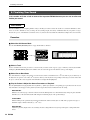
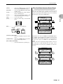
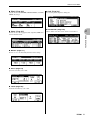
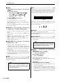
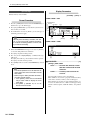
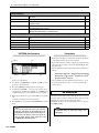
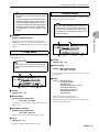
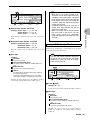
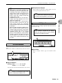
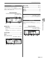
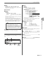
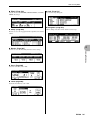
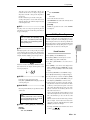
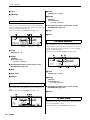
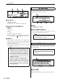
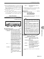
8 SEQUENCE PLAY FX Controls
In addition to the functions described here, these knobs are
fully assignable and can be set up to control a wide range
of functions and parameters.
Since the knobs allow continuous parameter control for the
selected track, they can be used for creative real-time performance sound control. 2 functions can be assigned to
each knob, selected by the [SELECT] button to their right,
allowing the three knobs to control up to 6 different parameters or functions.
The default assignments for these knobs are the main
PLAY EFFECT and MIDI DELAY parameters. Refer to
“Chapter 2: The Pattern mode”, pages 87 and 90, for more
information on PLAY EFFECTS and MIDI DELAY.
[BEAT STRETCH/GATE TIME] Knob
[CLOCK SHIFT/MIDI DELAY] Knob
SEQUENCE PLAY FX
SELECT
BEAT STRETCH CLOCK SHIFT
GATE TIME
MIDI DELAY
SWING
VELOCITY
[SWING/VELOCITY] Knob
[SELECT] Button
[BEAT STRETCH/GATE TIME] Knob
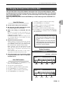
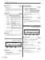
With the initial default settings, this knob provides realtime control of the PLAY FX BEAT STRETCH and GATE
TIME parameters.
BEAT STRETCH compresses or expands the length of
measures (Page 89), while GATE TIME alters the gate
time of the notes (Page 88).
[CLOCK SHIFT/MIDI DELAY] Knob
With the initial default settings, this knob provides realtime control of the PLAY FX CLOCK SHIFT and MIDI
DELAY parameters.
CLOCK SHIFT shifts the timing of notes (Page 89), while
MIDI DELAY adjusts the delay time of the MIDI DELAY
effect (Page 91).
RS7000 13
The Controls & Connectors
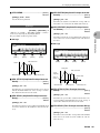
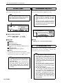
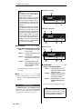
[SWING/VELOCITY] Knob
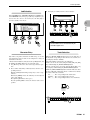
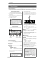
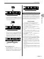
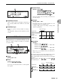
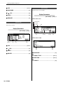
0 LFO Knobs
With the initial default settings, this knob provides realtime control of the PLAY FX SWING and VELOCITY
parameters.
SWING adjusts the timing of the 8th-note up (back) beats
to create a bounce or swing feel (Page 89). VELOCITY
adjusts the velocity of the notes (Page 88).
In addition to the functions described here, these knobs are
fully assignable and can be set up to control a wide range
of functions and parameters.
Since the knobs allow continuous parameter control for the
selected track, they can be used for creative real-time performance sound control. 3 functions can be assigned to the
[DEPTH] knob, selected by the [AMP/FILTER/PITCH] button B to its right.
The default assignments for these knobs are the main LFO
parameters.
[SELECT] Button
Selects one of the two functions/parameters assigned to
each knob. The indicator next to the currently selected
parameters will light.
[WAVE] Button
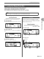
9 [EFFECT SEND/VOLUME] Knobs
In addition to the functions described here, these knobs are
fully assignable and can be set up to control a wide range
of functions and parameters.
Since the knobs allow continuous parameter control for the
selected track, they can be used for creative real-time performance sound control.
The default assignments for these knobs are the main
MIXER parameters. Refer to “Chapter 2: The Pattern
mode”, page 69, for more information on the MIXER
parameters.
LFO
WAVE
SPEED
S&H
PGM
USER
[SPEED] Knob
DEPTH
[DEPTH] Knob
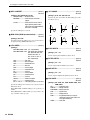
[SPEED] Knob (Page 98)
With the initial default settings, this knob provides realtime control of the LFO SPEED parameter.
[DEPTH] Knob (Page 98)
[DRY
VARI] Knob
[REVERB] Knob
EFFECT SEND / VOLUME
DRY
VARI
DELAY/CHO
REVERB
With the initial default settings, this knob provides realtime control of the LFO DEPTH parameter. Depending on
the function selected by the [AMP/FILTER/PITCH] button B, the [DEPTH] knob can control the depth of a tremolo, wow, or vibrato effect.
TRACK VOLUME
[WAVE] Button (Page 98)
[DELAY/CHO] Knob
[TRACK VOLUME] Knob
Selects the LFO waveform.
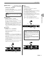
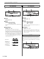
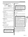
A [EG] Knobs
[DRY
VARI] Knob (Page 96)
With the initial default settings, this knob provides realtime control of the MIXER DRY SEND LEVEL parameter. This adjusts the level of the signal sent to the dry line.
[DELAY/CHO] Knob (Page 96)
With the initial default settings, this knob provides realtime control of the MIXER DELAY/CHORUS SEND
LEVEL parameter. This adjusts the level of the signal sent
to the delay or chorus effect.
[REVERB] Knob (Page 96)
With the initial default settings, this knob provides realtime control of the MIXER REVERB SEND LEVEL
parameter. This adjusts the level of the signal sent to the
reverb effect.
In addition to the functions described here, these knobs are
fully assignable and can be set up to control a wide range
of functions and parameters.
3 parameters are assigned to each knob, selectable via the
[AMP/FILTER/PITCH] button B.
Since the knobs allow continuous parameter control for the
selected track, they can be used for creative real-time performance sound control.
The default assignments for these knobs are the main
MIXER parameters. Refer to “Chapter 2: The Pattern
mode”, page 69, for more information on the MIXER
parameters.
[ATTACK] Knob
[SUSTAIN] Knob
EG
[TRACK VOLUME] Knob (Page 94)
With the initial default settings, this knob provides realtime control of the volume of the currently selected track.
ATTACK
DECAY
[DECAY] Knob
14 RS7000
SUSTAIN
RELEASE
[RELEASE] Knob
The Controls & Connectors
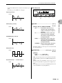
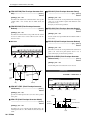
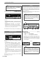
[ATTACK] Knob
[PORTAMENTO TIME] Knob (Page 100)
With the initial default settings, this knob provides realtime control of the AMPLITUDE EG, FILTER EG, or
PITCH EG ATTACK parameter. The target EG is selected
by the [AMP/FILTER/PITCH] button B.
With the initial default settings, this knob provides realtime control of the PORTAMENTO TIME parameter.
[PORTAMENTO TYPE] Button (Page 100)
Selects the PORTAMENTO type. The settings are selected
in sequence each time the button is pressed.
[DECAY] Knob
With the initial default settings, this knob provides realtime control of the AMPLITUDE EG, FILTER EG, or
PITCH EG DECAY parameter. The target EG is selected
by the [AMP/FILTER/PITCH] button B.
[SUSTAIN] Knob
With the initial default settings, this knob provides realtime control of the AMPLITUDE EG, FILTER EG, or
PITCH EG SUSTAIN parameter. The target EG is selected
by the [AMP/FILTER/PITCH] button B.
D FILTER Knobs
In addition to the functions described here, these knobs are
fully assignable and can be set up to control a wide range
of functions and parameters.
Since the knobs allow continuous parameter control for the
selected track, they can be used for creative real-time performance sound control.
The default assignments for these knobs are the main FILTER parameters.
[RELEASE] Knob
With the initial default settings, this knob provides realtime control of the AMPLITUDE EG, FILTER EG, or
PITCH EG RELEASE parameter. The target EG is
selected by the [AMP/FILTER/PITCH] button B.
[CUTOFF] Knob
[ENV. DEPTH] Knob
FILTER
+
-
TYPE
B [AMP/FILTER/PITCH] Button
Selects the parameter to be controlled by the LFO and EG
knobs. The indicator light in sequence each time the button
is pressed, indicating the currently selected parameter:
AMP → FILTER → PITCH → AMP, etc.
CUTOFF
RESONANCE
ENV.DEPTH
[RESONANCE] Knob
LPF24
LPF18
LPF12
HPF
BPF
BEF
[TYPE] Button
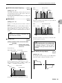
[CUTOFF] Knob (Page 103)
C PITCH Knobs
In addition to the functions described here, these knobs are
fully assignable and can be set up to control a wide range
of functions and parameters.
Since the knobs allow continuous parameter control for the
selected track, they can be used for creative real-time performance sound control.
The default assignments for these knobs are the PITCH
BEND and PORTAMENTO TIME parameters.
[PITCH BEND] Knob
[PORTAMENTO TYPE] Button
PITCH
PORTAMENTO
TYPE
FINGERED
With the initial default settings, this knob provides realtime control of filter CUTOFF.
[RESONANCE] Knob (Page 103)
With the initial default settings, this knob provides realtime control of filter RESONANCE.
[ENV. DEPTH] Knob (Page 103)
With the initial default settings, this knob provides realtime control of filter ENVELOPE DEPTH.
[TYPE] Button (Page 103)
Selects the filter type. The settings are selected in sequence
each time the button is pressed.
FULL TIME
OFF
PITCH BEND
PORTAMENTO TIME
[PORTAMENTO TIME] Knob
[PITCH BEND] Knob (Page 101)
With the initial default settings, this knob provides realtime control of PITCH BEND.
RS7000 15
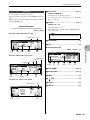
The Controls & Connectors
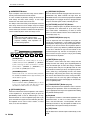
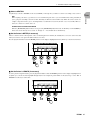
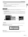
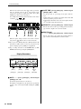
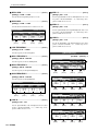
The Top Panel (Lower Section)
EM
F
F1
F2
G
F3
J
H
I
F4
MODE
PATT
CHAIN
PATTERN
NUM
BPM
REC
SONG
UTILITY
GROOVE
PLAY FX
MIDI DELAY
MIXER
PLAY
STOP
7
8
9
+/-
VOICE EDIT
EFFECT
SETUP
MASTER
4
5
6
0
SAVE
LOAD
JOB
EDIT
1
2
3
ENTER
SHIFT
MUTE
KEYBOARD
OCT
DOWN
ARPEGGIO
ON
OCT
UP
STORE
L
1
SCENE
2
MEMORY
3
4
5
EXIT
N K
A
SECTION
B
C
D
E
F
UTILITY
SYSTEM
MIDI SETUP
MIDI FILTER
SUB MODE
G
H
I
J
GROOVE
PLAY FX
GRID GROOVE HARMONIZE
NOTE
TIME
MIDI DELAY
MIDI DELAY
FEEDBACK
MIXER
VOICE SELECT
VOL/PAN/OUT
EQ
EFFECT SEND
LEVEL
VOICE EDIT
EFFECT
SETUP
MASTER
LFO
EFFECT TYPE ARPEGGIO
MASTER EQ
PORTAMENTO VARIATION
A/D SETUP
MASTER
DELAY
PITCH
KNOB ASSIGN EFFECT
MIDI OUT CH
REVERB
EG
FILTER
SAVE
SAVE
EXPORT
RENAME
DELETE
FORMAT
LOAD
LOAD
IMPORT
SCSI SETUP
SCSI COMM
JOB
JOB LIST
EDIT
EDIT CHANGE
VIEW FILTER
TAP
PAD 1
PAD 2
SPACE
DEL
TRANSPOSE
O
CAPS
ALL
1
TRACK
1~8
2
TR-
9~16
3
4
5
PAD ASSIGN
TR+
6
7
8
9
10
11
12
13
14
15
16
MUTE
P
SOLO
K !
Q
L #
M $
N %
O &
P '
Q (
TRANSPOSE(-)
3.3V
TRACK
SELECT
R )
S -
T @
U ^
V _
W {
X }
Y ~
Z
TRANSPOSE(+)
CARD
U
R
S
T
E [SHIFT] Button
[ ■ ](STOP) Button
Access several secondary functions when used in conjunction with other buttons and controls.
Stops pattern or song playback or recording.
F Sequencer Buttons
Starts pattern or song playback, and starts phrase or song
recording. When playback or recording is started, the [ ]
button indicator flashes at the current BPM (the indicator
lights continuously in the STEP recording mode).
The sequencer buttons control recording and playback in
the PATTERN and SONG modes.
[●](REC) Button [■](STOP) Button
REC
STOP
[
[
[
] Button
[
] Button
] Button
[
](Fast Reverse) Button
Moves back one measure when pressed briefly, or scrolls
backward continuously (fast reverse) when held.
PLAY
[
[
](PLAY) Button
](PLAY) Button
](Fast Forward) Button
Moves forward one measure when pressed briefly, or
scrolls forward continuously (fast forward) when held.
G LED Display
[●](REC) Button
Switches to the phrase or song recording display. The indicator will light when the button is press to engage the
record standby mode.
[
](Top) Button
Goes directly to the top measure of the current pattern or
song.
16 RS7000
Displays the current BPM or measure number. The LED
display also briefly displays the current value set by a knob
while the knob is operated.
Whether the LED display normally shows BPM or the measure number is determined by the setting in the UTILITY
mode System page (Page 258).
The Controls & Connectors
H MODE Buttons
[GROOVE] Button
Select the main RS7000 operating mode. The indicator
above the selected MODE button will light.
Selects the GROOVE quantize sub mode.
[PATTERN] Button
Selects the PLAY FX sub mode and the various display
pages provided.
[SONG] Button
MODE
PATTERN
PATT
CHAIN
SONG
[PLAY FX] Button
UTILITY
[MIDI DELAY] Button
Selects the MIDI DELAY sub mode and the various display pages provided.
[MIXER] Button
[PATT CHAIN] Button
[UTILITY] Button
Selects the MIXER sub mode and the various display
pages provided.
[PATTERN] Button (Page 70)
[VOICE EDIT] Button
Selects the PATTERN mode. The PATTERN Play and
PATTERN Patch modes are selected alternately each time
the button is pressed.
Selects the VOICE EDIT sub mode and the various display
pages provided.
[EFFECT] Button
[PATT CHAIN] Button (Page158)
Selects the PATTERN CHAIN mode.
Selects the EFFECT sub mode and the various display
pages provided.
[SONG] Button (Page180)
[SETUP] Button
Selects the SONG mode.
Selects the SETUP sub mode and the various display
pages provided.
[UTILITY] Button (Page256)
Selects the UTILITY mode. After entering the UTILITY
mode the [UTILITY] button sequentially selects the various pages provided.
[MASTER] Button
Selects the MASTER sub mode and the various display
pages provided.
I SUB MODE Buttons
[SAVE] Button
These buttons access the various sub modes available
within each of the main modes. When a sub mode includes
more than on display page, the pages are sequentially
selected each time the button is pressed.
Selects the SAVE sub mode and the various display pages
provided.
[LOAD] Button
Selects the LOAD sub mode and the various display pages
provided.
SUB MODE
GROOVE
PLAY FX
MIDI DELAY
MIXER
7
8
9
+/-
VOICE EDIT
EFFECT
SETUP
MASTER
4
5
6
0
SAVE
LOAD
JOB
EDIT
1
2
3
ENTER
[JOB] Button
Selects the PATTERN, PATTERN CHAIN, or SONG JOB
sub mode and the various display pages provided.
[EDIT] Button
Selects the PATTERN, PATTERN CHAIN, or SONG
EDIT sub mode and the various display pages provided.
J [EXIT] Button
Moves backward (upward) through the sub mode display
pages, or out of the current sub mode back to the main
mode.
RS7000 17
The Controls & Connectors
K SCENE/MUTE Buttons
M [ARPEGGIO ON] Button
Up to 5 complete scene and mute setups can be stored in
memory and recalled at the touch of a button.
A “scene” includes all parameter settings for all tracks (all
knob settings and mute on/off settings). A mute setup
includes the mute on/off status for all tracks.
The ability to store and instantly recall complete scene and
mute setups means that even complex setups that would
take a considerable amount of time to program in real time
can be called up at the touch of a button. Recall operations
can be recorded to pattern chains and songs as well.
Turns the RS7000 automatic arpeggio feature on or off. The
[ARPEGGIO ON] button indicator will light when the
ARPEGGIO feature is on, and notes played on the keyboard
will be played as an arpeggio. To turn the arpeggio function
off press the button again so that its indicator goes out.
NOTE
• Scenes do not include sequence data.
• Scene/mute setups cannot be stored during
sequence recording. Store operations are
possible during playback.
MUTE
STORE
SCENE
1
2
MEMORY
3
4
5
N [OCT DOWN] and [OCT UP] Buttons
The [OCT DOWN] and [OCT UP] buttons allow the pitch of
the keyboard to be shifted down or up in octave steps.
Press both buttons simultaneously to return to normal
pitch. The current amount of octave shift is indicated on the
LCD display. (Page 73)
O [TRANSPOSE] Button (Page 73)
Used in conjunction with the keyboard to transpose the
overall pitch. Transposition is set by holding the [TRANSPOSE] button and pressing the key on the keyboard corresponding to the desired amount of transposition above or
below the E (track 8) key. While the [TRANSPOSE] button
is held the E indicator will light and the indicator of the
selected transpose key will flash. To transpose by more
than an octave first press the [OCT UP] or [OCT DOWN]
button and then the keyboard.
[STORE] Button
P [MUTE] Button (Page 74)
Store the current scene or mute settings to one of the 5
available memory locations: [MEMORY 1] ~ [MEMORY
5]. The selected type of data is stored when a scene/mute
memory button — [MEMORY 1] ~ [MEMORY 5] — is
pressed while the [STORE] button is held.
This button is used to make track mute settings and solo
settings.To make mute settings, press the [MUTE] button to
make the indicator light. To make solo settings, hold down
the [SHIFT] button and press the [MUTE] button to make
the indicator flash. When you do so, the keyboard pad indicators (white keys) corresponding to tracks that contain
data will light, and pressing one of these keys will engage
the mute or solo function for that track, causing the indicator to flash. Press the same key again to disengage the
mute function for that track. To disengage the solo function,
press the [MUTE] button.
[SCENE/MUTE] Button
Switches between the scene and mute memory functions.
The SCENE and MUTE indicators light alternately each
time the button is pressed.
[MEMORY 1] ~ [MEMORY 5] Button
Used in conjunction with the [STORE] button (see above)
to store scene or mute setups, and when pressed alone
these buttons recall the stored scene or mute data.
L [KEYBOARD] Button
Determines whether the RS7000 keyboard is to be used as
a music keyboard (i.e., to play notes). When you press the
[KEYBOARD] button so that its indicator lights, the keyboard will function as a music keyboard to play notes. If you
press the button once again so that the indicator goes dark,
the keyboard can be used to select sections, to select
tracks, or as track mute buttons.
Q [TRACK SELECT] Button (Page 67)
Used in conjunction with the keyboard to select a track for
recording or other operations. Tracks are selected by pressing the appropriate white key on the keyboard while holding
the [TRACK SELECT] button.
R Keyboard
The keyboard is used like a conventional keyboard to enter
performance data, as well as to select sections, select
tracks, mute and solo tracks, set transposition, and more.
Normally the number “6” key corresponds to middle C. The
keyboard does not respond to velocity or aftertouch.
S [TAP] Button
Tap this button at the desired tempo to automatically set the
BPM.
18 RS7000
The Controls & Connectors
T [PAD 1] and [PAD 2]
U CARD Slot
Velocity-sensitive pads for performance data entry. Tapping
these pads enters the pre-specified note data at the specified pitch. The pitch for each pad can be set by playing the
appropriate key on the keyboard while holding the [TAP]
button and [PAD 1] or [PAD 2].
Slot for memory card insertion.
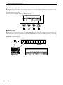
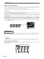
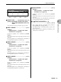
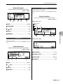
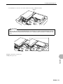
The Rear Panel
1
4
5
6
THIS CLASS B DIGITAL APPARATUS COMPLIES WITH CANADIAN ICES-003.
MUSICAL INSTRUMENT
379U
CET APPAREIL NUMÉRIQUE DE LA CLASSE B EST CONFORME À LA NORME NMB-003
DU CANADA.
MIDI
US LISTED
7
8
9
THIS DEVICE COMPLIES WITH PART 15 OF THE FCC RULES. OPERATION IS SUBJECT TO THE
FOLLWWING TWO CONDITIONS:
(1)THIS DEVICE MAY NOT CAUSE HARMFUL INTERFERENCE,AND
(2)THIS DEVICE MUST ACCEPT ANY INTERFERENCE RECIVED,INCLUDING INTERFERENCE
THAT MAY CAUSE UNDESIRED OPERATION.
IN
POWER
ON/ OFF
INPUT
CAUTION
SCSI
RISK OF ELECTRIC SHOCK
DO NOT OPEN
ATTENTION : RISQUE DE CHOC ÉLECTRIQUE NE PAS OUVRIR.
REDUCE THE RISK OF FIRE OR ELECTRIC SHOCK,
WARNING TO
DO NOT EXPOSE THIS PRODUCT TO RAIN OR MOISTURE.
FOOT SW
CONTRAST
R
L
R
OUTPUT
L/MONO
PHONES
OUT A
AC INLET
MODEL
SER. NO.
OUT B
MADE IN JAPAN
2
3
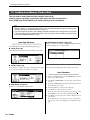
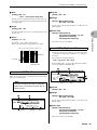
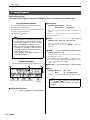
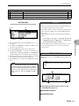
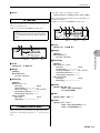
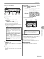
1 POWER Switch
Press in to turn the RS7000 on, and press again to turn it
off.
2 AC INLET
The AC power cable supplied with the RS7000 is plugged
in here. Use only the supplied cable.
3 MIDI IN, OUT A, and OUT B Connectors
If you plan to use a MIDI keyboard or other instrument to
play and program the RS7000, it should be connected to
the MIDI IN connector.
The MIDI OUT A and B connectors can be connected to an
external tone generator or synthesizer if you want to transmit performance data, button and knob operations, and pad
operations to external equipment from the RS7000.
4 SCSI Connector
External SCSI storage devices (hard disks, CD-ROM
drives, etc.) can be connected here. The connector is a 50pin half-pitch type.
5 FOOT SW Jack
An optional Yamaha FC4 or FC5 footswitch connected to
this jack can be used for start/stop, section selection, sustain, or tap BPM entry.
6 CONTRAST Control
Use the CONTRAST control to achieve the best LCD display visibility (LCD visibility varies with viewing angle).
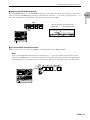
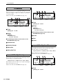
7 INPUT L and R Jacks
Analog mono or stereo signals can be connected here for
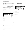
sampling (recording). Connect mono signals to either the L
or R jack.
8 OUTPUT L/MONO & R Jacks
These are the main stereo outputs from the RS7000. When
a plug is inserted into only the L/MONO output, the left- and
right-channels signals are mixed and delivered via that output to allow direct connection to mono sound systems.
9 PHONES Jack
Any pair of stereo headphones with a 1/4” stereo phone
plug can be plugged in here for convenient monitoring. The
PHONES output level is adjusted via the MASTER VOLUME control.
RS7000 19
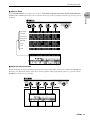
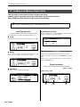
The Controls & Connectors
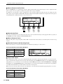
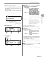
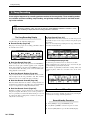
Rear Panel with Optional AIEB2 I/O
Expansion Board Installed
THIS CLASS B DIGITAL APPARATUS COMPLIES WITH CANADIAN ICES-003.
MUSICAL INSTRUMENT
379U
CET APPAREIL NUMÉRIQUE DE LA CLASSE B EST CONFORME À LA NORME NMB-003
DU CANADA.
MIDI
US LISTED
THIS DEVICE COMPLIES WITH PART 15 OF THE FCC RULES. OPERATION IS SUBJECT TO THE
FOLLWWING TWO CONDITIONS:
(1)THIS DEVICE MAY NOT CAUSE HARMFUL INTERFERENCE,AND
(2)THIS DEVICE MUST ACCEPT ANY INTERFERENCE RECIVED,INCLUDING INTERFERENCE
THAT MAY CAUSE UNDESIRED OPERATION.
IN
POWER
ON/ OFF
INPUT
CAUTION
SCSI
RISK OF ELECTRIC SHOCK
DO NOT OPEN
ATTENTION : RISQUE DE CHOC ÉLECTRIQUE NE PAS OUVRIR.
REDUCE THE RISK OF FIRE OR ELECTRIC SHOCK,
WARNING TO
DO NOT EXPOSE THIS PRODUCT TO RAIN OR MOISTURE.
FOOT SW
CONTRAST
R
L
R
OUTPUT
L/MONO
PHONES
OUT A
AC INLET
MODEL
SER. NO.
OPTICAL
OUT B
IN
OUT
IN
DIGITAL
OUT
AS6
AS5
ASSIGNABLE OUT
AS4
AS3
AS2
AS1
MADE IN JAPAN
1
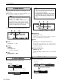
1 OPTICAL IN, OUT Connectors
Digital input and output for connection via optical cable.
Digital signals to be recorded (48 kHz, 44.1 kHz, or 32 kHz
fs) can be connected to OPTICAL IN. OPTICAL OUT delivers the same signal as the OUTPUT L/MONO and R jacks
in digital form (fs = 44.1 kHz).
2 DIGITAL IN, OUT Connectors
Digital input and output in S/P DIF format (the format normally used by home-use CD or DAT equipment) for connection via coaxial (RCA-pin) cable. Digital signals to be
recorded (48 kHz, 44.1 kHz, or 32 kHz fs) can be connected to DIGITAL IN. DIGITAL OUT delivers the same signal as the OUTPUT L/MONO and R jacks in digital form (fs
= 44.1 kHz).
3 ASSIGNABLE OUT 1 ~ 6 Jacks
Unlike the STEREO OUT outputs, the output from individual tracks can be assigned to these outputs. (Page 21)
The ASSIGNABLE OUT jacks can be used as mono outputs or as stereo pairs (1&2, 3&4, 5&6).
20 RS7000
2
3
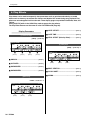
Options
A range of options are available to give the RS7000 even greater
music production capabilities.
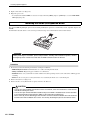
Expansion Memory (SIMM)
Recorded samples and samples loaded from memory card must
be stored in the internal memory in order to be played.
The RS7000 comes equipped with 4 MB of memory which
allows up to 46 seconds of monaural sample recording or playback at the maximum 44.1 kHz sampling frequency. Additional
memory (SIMM) can be installed to allow much longer sample
recording and playback. If you need longer sample recording and
playback time, or want to keep a large number of samples in
memory at the same time, you may need to add extra memory.
See page 274 of the Appendix for details on installing extra memory.
Notes on Musical Copyright
Precautions for Purchasing Expansion SIMM
Memory
Some types of commonly available SIMM memory may not
work properly with the RS7000, and we cannot guarantee operation with untested memory types. Please check with the retail
outlet where you purchased your RS7000, or an authorized
Yamaha representative, before purchasing expansion SIMM
memory.
IMPORTANT
• Use only 4, 8, 16, or 32 megabyte 72-pin SIMMs
with an access time faster than 70ns. x32bit SIMMs
are the standard, but x36bit types (with parity) can
also be used.
• Always install SIMMs in pairs of the same capacity.
A single SIMM will not work.
• The RS7000 comes with 4 megabytes of preinstalled sample memory. Thus if you install a pair of
16 megabyte SIMMs (32 megabytes total) you will
have 36 megabytes (32 + 4 megabytes) of sample
memory. However, since the maximum allowable
sample memory for the RS7000 is 64 megabytes, if
you install a pair of 32 megabyte SIMMs (64 megabytes total) the initial 4 megabytes will not be used.
• SIMMs which use more than 19 memory chips per
unit may not function properly with the RS7000.
Please choose SIMMs which use 18 or fewer memory chips.
• We recommend SIMMs which conform to JEDEC*
standards. However, even though a SIMM which
conforms to the JEDEC internal circuit configuration
functions perfectly in a computer, there is no guarantee that it will work properly with the RS7000.
*JEDEC stands for the “Joint Electron Device
Engineering Council”, a group which sets standards for the configurations of electronic
devices.
AIEB2 I/O Expansion Board
Initially the RS7000 can only record samples from analog
sources, and only analog output capability is provided. With the
optional AIEB2 I/O Expansion Board, however, you gain optical
and coaxial terminals for direct digital signal input and output.
Also, 6 assignable outputs (ASSIGNABLE OUT 1 ~ 6) are provided in addition to the standard OUTPUT jacks.
Refer to page 276 in the Appendix for details on installing the
AIEB2 I/O Expansion Board.
NOTE
The AIEB1 expansion I/O board cannot be
used.
Notes on Musical Copyright
The RS7000 supports SCMS (Serial Copy Management System) to protect the copyrights of music software.
Data that was digitally sampled from a CD or other source cannot be saved to a memory card or SCSI disk in WAV format, or transferred
via the TWE wave editor as sample data. If you wish to save this data, you must save it in the RS7000’s own format.
It is prohibited to use copyrighted songs and sound data (that can be recorded via the RS7000) for commercial purposes. It is also prohibited to reproduce, transfer, or distribute the data, or play the data for a commercial audience
without permission from the owners of the copyright, except for personal use or application that does not infringe the
copyright. If you wish to use such data for occasions other than personal use, consult a copyright expert. Yamaha is
not responsible for any data created, reproduced, or edited using the RS7000, nor for any reproduction or use of
such data.
RS7000 21
Preparation and Setup
Preparation and Setup
Power supply and other equipment connections will be described in this section.
Power Connection
Connecting to Audio Equipment
WARNING
CAUTION
Connections with external equipment must be made
with the power of the RS7000 and peripheral equipment turned off. Making connections with the power
on may damage your amp or speakers.
• Be sure that the RS7000’s power switch is OFF
before you connect the cord.
• Make sure your RS7000 is rated for the AC voltage
supplied in the area in which it is to be used (as
listed on the rear panel). Connecting the unit to the
wrong AC supply can cause serious damage to the
internal circuitry and may even pose a shock hazard!
• Use only the AC power cord supplied with the
RS7000. If the supplied cord is lost or damaged and
needs to be replaced, contact your Yamaha dealer.
The use of an inappropriate replacement can pose a
fire and shock hazard!
• The type of AC power cord provided with the
RS7000 may be different depending on the country
in which it is purchased (a third prong may be provided for grounding purposes). Improper connection
of the grounding conductor can create the risk of
electrical shock. Do NOT modify the plug provided
with the RS7000. If the plug will not fit the outlet,
have a proper outlet installed by a qualified electrician. Do not use a plug adaptor which defeats the
grounding conductor.
• The RS7000 is designed for use with a grounded
line (three-prong outlet). The power cord includes a
grounding pin to prevent electrical shock and damage to equipment.
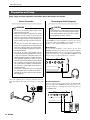
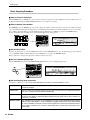
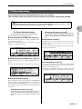
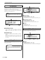
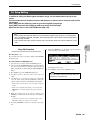
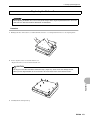
The RS7000 has no internal amplifier or speakers of its own. To
monitor the sound of the RS7000, connect headphones, powered
speakers, or other playback equipment as required.
■ Headphones
If you are using headphones, connect them to the rear panel
PHONES (headphones) jack. When using headphones, adjust the
MASTER VOLUME control to an appropriate level that will not
harm your hearing. The rear-panel OUTPUT L/MONO and R
jacks are active even when headphones are connected.
INPUT
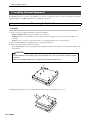
R
Connect the supplied power cord to the AC inlet on the rear
panel. Then plug the other end of the cord into a 3-prong wall
outlet.
AC INLET
MODEL
SER. NO.
L
R
OUTPUT
L/MONO
PHONES
■ Powered Speakers
Connect a pair of powered speakers (such as the Yamaha CBXS3) to the output jacks (L/MONO, R) using appropriate connection cables. If you are connecting only one powered speaker, use
the L/MONO jack.
M
THAT MAY CAUSE UNDESIRED OPERATION.
INPUT
SW
22 RS7000
CONTRAST
R
L
R
OUTPUT
L/MONO
PHONES
Preparation and Setup
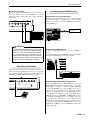
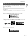
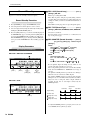
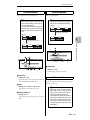
■ Connecting to a Mixer
Connect the output jacks (L/MONO, R) to two channels of the
mixer. The channel connected to the L/MONO jack should be
panned left, and the channel connected to the R jack should be
panned right.
INPUT
SW
CONTRAST
R
L
R
OUTPUT
L/MONO
PHONES
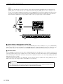
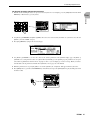
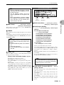
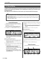
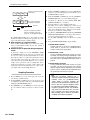
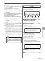
Connecting External MIDI Devices
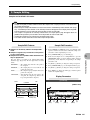
■ Connecting a tone generator module
RS7000 sequence playback data can be used to play an external
tone generator module. Use a MIDI cable to connect the MIDI
OUT connector on the rear panel to the MIDI IN connector of the
external MIDI device.
MUSIC PRODUCTION STUDIO
Integrated Sampling Sequencer
MASTER EFFECT
SAMPLING
MULTI COMP
CTRL DELAY
D-FILTER
ISOLATION
EFFECT
ON/OFF
RING MOD
V-DIST
LO-FI
SLICE
REAL TIME
LOOP
REMIX
SAMPLE
EDIT
IN
STANDBY
OUT A
OUT B
START/STOP
MIDI
REC VOLUME
MASTER VOLUME
EFFECT SEND / VOLUME
SEQUENCE PLAY FX
SELECT
BEAT STRETCH CLOCK SHIFT
GATE TIME
MIDI DELAY
SWING
VELOCITY
DRY
VARI
DELAY/CHO
REVREB
TRACK VOLUME
EG
LFO
WAVE
S&H
PGM
USER
SPEED
AMP
FILTER
PITCH
DEPTH
ATTACK
DECAY
SUSTAIN
RELEASE
FILTER
PITCH
+
-
PORTAMENTO
TYPE
FINGERED
LPF24
LPF18
LPF12
HPF
TYPE
FULL TIME
OFF
PITCH BEND
F1
F2
F3
PORTAMENTO TIME
CUTOFF
RESONANCE
MIDI OUT
A or B
MIDI
IN
Tone generator
module
BPF
BEF
ENV.DEPTH
F4
MODE
PATT
CHAIN
PATTERN
NUM
UTILITY
GROOVE
PLAY FX
MIDI DELAY
MIXER
GROOVE
PLAY FX
GRID GROOVE HARMONIZE
NOTE
TIME
PLAY
STOP
7
8
9
+/-
VOICE EDIT
EFFECT
SETUP
MASTER
MUTE
KEYBOARD
ARPEGGIO
ON
OCT
DOWN
OCT
UP
STORE
1
SCENE
2
MEMORY
3
8
9
4
4
5
EXIT
5
SAVE
B
C
D
E
F
G
H
6
LOAD
1
A
JOB
2
I
3
J
MIDI DELAY
MIDI DELAY
FEEDBACK
MIXER
VOICE SELECT
VOL/PAN/OUT
EQ
EFFECT SEND
LEVEL
VOICE EDIT
EFFECT
SETUP
MASTER
LFO
EFFECT TYPE ARPEGGIO
MASTER EQ
A/D SETUP
PORTAMENTO VARIATION
MASTER
PITCH
KNOB ASSIGN EFFECT
DELAY
EG
REVERB
MIDI OUT CH
FILTER
SHIFT
SECTION
UTILITY
SYSTEM
MIDI SETUP
MIDI FILTER
SUB MODE
BPM
REC
SONG
0
EDIT
SAVE
SAVE
EXPORT
RENAME
DELETE
FORMAT
ENTER
LOAD
LOAD
IMPORT
SCSI SETUP
SCSI COMM
JOB
JOB LIST
EDIT
EDIT CHANGE
VIEW FILTER
TAP
PAD 1
PAD 2
SPACE
DEL
TRANSPOSE
CAPS
ALL
1
TRACK
1~8
2
TR-
9~16
3
4
5
PAD ASSIGN
TR+
6
7
10
11
12
13
14
15
16
MUTE
SOLO
K !
L #
M $
N %
O &
P '
Q (
TRANSPOSE(-)
TRACK
SELECT
3.3V
R )
S -
T @
U ^
V _
W {
X }
Y ~
Z
TRANSPOSE(+)
CARD
CAUTION
Do not connect the output jacks of the RS7000
to the mic input jacks of an amp or cassette
deck etc. If they are connected to mic inputs,
the sound quality may be impaired, and the
device may be damaged. Also, when connecting the RS7000 to a mixer or similar device, set
the mixer channels to Line Input sensitivity.
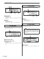
■ Connecting a MIDI keyboard
Real-time recording input will be easier if you use a MIDI keyboard.
Use a MIDI cable to connect the MIDI OUT of the external MIDI
keyboard to the MIDI IN connector on the rear panel.
THIS CLASS B DIGITAL APPARATUS COMPLIES WITH
MUSICAL INSTRUMENT
379U
CET APPAREIL NUMÉRIQUE DE LA CLASSE B EST C
DU CANADA.
MIDI
US LISTED
IN
CAUTION
SCSI
RISK OF ELECTRIC SHOCK
DO NOT OPEN
N : RISQUE DE CHOC ÉLECTRIQUE NE PAS OUVRIR.
O REDUCE THE RISK OF FIRE OR ELECTRIC SHOCK,
DO NOT EXPOSE THIS PRODUCT TO RAIN OR MOISTURE.
Connecting a Footswitch
MODEL
OUT A
SER. NO.
OUT B
MADE IN JAPAN
When using an optional FC4 or FC5 footswitch, insert the footswitch plug into the FOOT SW jack located on the rear panel.
The footswitch function is determined by the UTILITY mode
SYSTEM page FOOT SWITCH parameter (Page 257).
THAT MAY CAUSE UNDESIRED OPERATION.
INPUT
SCSI
FOOT SW
CONTRAST
R
L
R
OUTPUT
L/MONO
MIDI OUT
PHONES
■ Connecting to an MTR (Multi-track Recorder)
Since the RS7000 implements MTC (MIDI Time Code) and
MMC (MIDI Machine Control), you can produce music while
synchronized to a MTC- or MMC-compatible multi-track
recorder. The RS7000 does not generate MTC on it’s own, so
you’ll need an optional MTC device such as the Yamaha
AW4416. Use MIDI cables to connect the MIDI OUT connector
of the RS7000 to the MIDI IN connector of the MTR, and the
MIDI IN connector of the RS7000 to the MIDI OUT connector
of the MTR. The RS7000 will sync to the MTC clock signal
received from the external device. If your MTR recognizes
MMC, then the start/stop, fast forward and rewind functions can
be remotely controlled from the RS7000. In this case go to the
UTILITY mode MIDI page and set the MIDI Sync parameter to
“MTC” (Page 260).
RS7000 23
Preparation and Setup
RS7000 Synchronized to External MTC
3. Turn the power to audio equipment on, then turn the RS7000
and audio volumes up to a reasonable listening level.
MUSIC PRODUCTION STUDIO
Integrated Sampling Sequencer
MASTER EFFECT
SAMPLING
MULTI COMP
CTRL DELAY
D-FILTER
ISOLATION
EFFECT
ON/OFF
RING MOD
V-DIST
LO-FI
SLICE
REAL TIME
LOOP
REMIX
SAMPLE
EDIT
IN
STANDBY
OUT A
OUT B
START/STOP
MIDI
REC VOLUME
MASTER VOLUME
EFFECT SEND / VOLUME
SEQUENCE PLAY FX
SELECT
BEAT STRETCH CLOCK SHIFT
GATE TIME
MIDI DELAY
SWING
VELOCITY
DRY
VARI
DELAY/CHO
REVREB
TRACK VOLUME
EG
LFO
WAVE
S&H
PGM
USER
SPEED
AMP
FILTER
PITCH
DEPTH
ATTACK
DECAY
SUSTAIN
RELEASE
FILTER
PITCH
+
-
PORTAMENTO
TYPE
FINGERED
LPF24
LPF18
LPF12
HPF
TYPE
FULL TIME
OFF
PITCH BEND
F1
F2
F3
PORTAMENTO TIME
CUTOFF
RESONANCE
BPF
BEF
ENV.DEPTH
F4
MIDI
OUT
MIDI
IN
Multi-track
Recorder
MODE
PATT
CHAIN
PATTERN
NUM
UTILITY
UTILITY
SYSTEM
MIDI SETUP
MIDI FILTER
SUB MODE
BPM
STOP
REC
SONG
GROOVE
PLAY FX
MIDI DELAY
MIXER
GROOVE
PLAY FX
GRID GROOVE HARMONIZE
NOTE
TIME
PLAY
7
8
9
+/-
VOICE EDIT
EFFECT
SETUP
MASTER
MUTE
KEYBOARD
OCT
DOWN
ARPEGGIO
ON
OCT
UP
STORE
1
SCENE
2
MEMORY
3
8
9
4
4
5
EXIT
5
SAVE
B
C
D
E
F
G
6
LOAD
1
A
SECTION
0
JOB
2
H
EDIT
3
I
SAVE
SAVE
EXPORT
RENAME
DELETE
FORMAT
ENTER
J
MIDI DELAY
MIDI DELAY
FEEDBACK
MIXER
VOICE SELECT
VOL/PAN/OUT
EQ
EFFECT SEND
LEVEL
VOICE EDIT
EFFECT
SETUP
MASTER
LFO
EFFECT TYPE ARPEGGIO
MASTER EQ
A/D SETUP
PORTAMENTO VARIATION
MASTER
PITCH
KNOB ASSIGN EFFECT
DELAY
EG
MIDI OUT CH
REVERB
FILTER
SHIFT
LOAD
LOAD
IMPORT
SCSI SETUP
SCSI COMM
JOB
JOB LIST
EDIT
EDIT CHANGE
VIEW FILTER
TAP
PAD 1
PAD 2
SPACE
DEL
TRANSPOSE
CAPS
1~8
ALL
1
TRACK
2
9~16
3
TR-
4
5
MASTER VOLUME
PAD ASSIGN
TR+
6
7
10
11
12
13
14
15
16
MUTE
SOLO
K !
L #
M $
N %
O &
P '
Q (
R )
S -
TRANSPOSE(-)
3.3V
TRACK
SELECT
T @
U ^
V _
W {
X }
Y ~
Z
TRANSPOSE(+)
CARD
4. If the display is not easily visible, use the CONTRAST con-
trol to adjust for optimum visibility.
* In this case MTC must be sent to the RS7000 from an external
MIDI device.
CONTRAST
RS7000 Controlling External Device via MMC
MUSIC PRODUCTION STUDIO
Integrated Sampling Sequencer
MASTER EFFECT
SAMPLING
MULTI COMP
CTRL DELAY
D-FILTER
ISOLATION
EFFECT
ON/OFF
RING MOD
V-DIST
LO-FI
SLICE
REAL TIME
LOOP
REMIX
SAMPLE
EDIT
IN
STANDBY
OUT A
OUT B
START/STOP
REC VOLUME
MASTER VOLUME
MIDI
EFFECT SEND / VOLUME
SEQUENCE PLAY FX
SELECT
BEAT STRETCH CLOCK SHIFT
GATE TIME
MIDI DELAY
SWING
VELOCITY
DRY
VARI
DELAY/CHO
REVREB
WAVE
S&H
PGM
USER
SPEED
AMP
FILTER
PITCH
DEPTH
ATTACK
DECAY
SUSTAIN
RELEASE
FILTER
PITCH
+
-
PORTAMENTO
TYPE
FINGERED
LPF24
LPF18
LPF12
HPF
TYPE
FULL TIME
OFF
PITCH BEND
F1
F2
F3
PORTAMENTO TIME
CUTOFF
RESONANCE
BPF
BEF
ENV.DEPTH
F4
MIDI
MIDI
OUT
SONG
UTILITY
GROOVE
PLAY FX
MIDI DELAY
MIXER
PLAY
7
8
9
+/-
VOICE EDIT
EFFECT
SETUP
MASTER
SHIFT
MUTE
KEYBOARD
ARPEGGIO
ON
OCT
DOWN
OCT
UP
STORE
1
SCENE
2
MEMORY
3
8
9
4
5
4
EXIT
5
SAVE
B
C
D
E
F
G
H
6
LOAD
1
A
SECTION
UTILITY
SYSTEM
MIDI SETUP
MIDI FILTER
SUB MODE
BPM
STOP
JOB
2
I
Multi-track
Recorder
IN
MODE
PATT
CHAIN
PATTERN
NUM
REC
5. Always turn the RS7000 power off after turning the volume
TRACK VOLUME
EG
LFO
3
J
0
EDIT
ENTER
GROOVE
PLAY FX
GRID GROOVE HARMONIZE
NOTE
TIME
MIDI DELAY
MIDI DELAY
FEEDBACK
MIXER
VOICE SELECT
VOL/PAN/OUT
EQ
EFFECT SEND
LEVEL
VOICE EDIT
EFFECT
SETUP
MASTER
LFO
EFFECT TYPE ARPEGGIO
MASTER EQ
A/D SETUP
PORTAMENTO VARIATION
MASTER
DELAY
PITCH
KNOB ASSIGN EFFECT
MIDI OUT CH
REVERB
EG
FILTER
SAVE
SAVE
EXPORT
RENAME
DELETE
FORMAT
LOAD
LOAD
IMPORT
SCSI SETUP
SCSI COMM
JOB
JOB LIST
A or B
all the way down or turning off all connected audio equipment.
EDIT
EDIT CHANGE
VIEW FILTER
TAP
PAD 1
PAD 2
SPACE
DEL
TRANSPOSE
CAPS
ALL
1
TRACK
1~8
2
TR-
9~16
3
4
5
PAD ASSIGN
TR+
6
7
10
11
12
13
14
15
16
MUTE
CAUTION
SOLO
K !
L #
M $
N %
O &
P '
Q (
TRANSPOSE(-)
TRACK
SELECT
3.3V
R )
S -
T @
U ^
V _
W {
X }
Y ~
Z
TRANSPOSE(+)
CARD
Turning Power On and Off
1. Make sure all peripheral equipment is properly connected to
the RS7000, and turn all audio volume controls down to minimum.
2. Turn the RS7000 power on after the peripheral devices.
MUSICAL INSTRUMENT
379U
MIDI
US LISTED
POWER
ON/ OFF
CAUTION
RISK OF ELECTRIC SHOCK
DO NOT OPEN
ATTENTION : RISQUE DE CHOC ÉLECTRIQUE NE PAS OUVRIR.
REDUCE THE RISK OF FIRE OR ELECTRIC SHOCK,
WARNING TO
DO NOT EXPOSE THIS PRODUCT TO RAIN OR MOISTURE.
AC INLET
MODEL
SER. NO.
MADE IN JAPAN
24 RS7000
The RS7000 system setup data is retained in
memory by a backup battery. When the backup
battery runs low, the “Backup Battery Low!”
warning will appear in the display. If the battery
runs down completely, the contents of memory
will be lost. If the “Backup Battery Low!” warning
appears, immediately save the data to a memory card (Smart Media) or an external SCSI
disk, and then have the backup battery replaced
by the qualified Yamaha service personnel.
Restoring the Initial Factory Settings
Restoring the Initial Factory Settings
The original RS7000 factory settings can be restored as follows.
When the factory settings are restored, all the voice and sequence data you created as well as the system
setup data will be erased. Be sure to save all important data to memory card (Smart Media) or SCSI disk
(Page 114, 166, 204) before performing this procedure.
[Procedure]
1. Turn the power OFF.
2. Turn the power ON while holding the [OCT DOWN], [OCT
UP] and [STORE] buttons.
MUTE
D
ARPEGGIO
ON
OCT
DOWN
OCT
UP
STORE
SCENE
1
POWER
ON/ OFF
RS7000 25
Restoring the Initial Factory Settings
26 RS7000
Tutorial
Although all the information you need to operate the RS7000 is available in
the reference section of this manual, you might want to take the time to go
through the tutorial in order to familiarize yourself with some of its most
important features in a step-by-step “linear” manner.
The tutorial is presented in 6 sections, outlined below, each of which builds
on the information presented in the previous section.
1. RS7000 System Overview ......................... 28
A quick look at the overall RS7000 system and what it can do.
2. Assemble a Pattern Using
Preset Phrases ........................................... 30
The fast, easy way to create patterns. Here we’ll create a pattern that we’ll
build on in the following sections.
3. Real-time Sound Control ............................ 38
A quick detour to try out some of the RS7000’s awesome real-time control
capabilities.
4. Recording Original Phrases....................... 39
Record an original phrase and add it to the basic pattern we created in section 2.
5. Add Samples ............................................... 43
Record a new sample and add it to our pattern.
6. Finalizing Your Sound ............................... 46
The final mix — fine-tuning the groove and adding effects.
Please note that the tutorial by no means covers all the capabilities and features of the RS7000. Important functions which are not included in the
tutorial — the SONG, EDIT and UTILITY modes, to name a few — are
described in detail in the reference section of the manual. Use the table of
contents and index to find detailed information on the features and functions you want to learn about. The same applies to features described here
in the tutorial: for full details on any feature, refer to the reference section.
RS7000
27
1. RS7000 System Overview
1. RS7000 System Overview
The Yamaha RS7000 brings it all together. Everything you need for professional-level music production
— particularly in dance, techno, R&B, and ambient genres — is included and flawlessly integrated in a
system that has been specifically designed to facilitate modern production techniques. The RS7000
combines a powerful, flexible sequencing system with a state-of-the-art tone generator loaded with an
awesome selection of drum kits and voices, and a sampler which allows you to sample your own
sounds and loops and easily incorporate them into your sequences. All of this is brought together with
an interface that is intuitive and easy while offering the depth and real-time control required by professional applications.
Powerful 16-track Sequencer
In the phrase-based PATTERN mode, complete patterns can be quickly assembled by combining individual phrases from
the 5980 preset phrases provided, or you can record your own using the extensive selection of drum kits and other voices
provided by the internal AWM2 tone generator. Sampled sounds, loops and break-beats can just as easily be added to the
sequence to create the groove your music demands. Your patterns can be used individually, or the PATTERN CHAIN mode
can be used to automatically sequence specified patterns to create even complex arrangements.
There’s also a SONG mode which functions as a 16-track sequencer with all the features and versatility you’d expect from
a full-blown stand-alone sequencer.
Real-time Control
Another key requirement for creative freedom in modern music production is real-time sound control. The RS7000 offers
plenty of sonic manipulation capability with a comprehensive range of knobs for hands-on control of BPM, filter parameters, envelopes, pitch, LFO, and more. The RS7000 also features a keyboard and velocity-sensitive pads that allow voices
and samples to be played in real time, as well as switching between sequence sections and tracks, and controlling the track
mute and solo functions. Scene and mute memory functions can be used to take “snapshots” of track mute setups or complete panel-control setups for instant recall when needed.
Advanced Sampling and Editing Features
In addition to directly loading sample data in a variety of popular formats, the RS7000 allows you to record your own samples from CDs or any line-level or microphone source. Once your samples are recorded they can be trimmed, sliced,
looped, and otherwise prepared for playback with the power and flexibility you’d expect from a stand-alone sampler. And
when your samples are ready, they can be incorporated into patterns and songs just as easily as the tone-generator voices.
You can even use the sampler to record vocal parts to take your project right up to the final production stage without using
any equipment other than the RS7000.
AWM2 Tone Generator
Even electronic sounds change with the times, and the RS7000 is right up to date. The internal AWM2 tone generator system offers more than 63 top-quality drum kits as well as 1054 pitched voices and sound effects — you’ll find what you
need for just about any musical genre. You also have a range of voice editing functions that make it easy to customize and
personalize the sound to bring your art to life.
An Extensive Range of Effects
In today’s music effects are almost as important as the sounds they are applied to. The RS7000 offers plenty of sound processing power with PLAY FX which function at the sequencing stage to provide harmonization as well as note and timing
variations; a three-stage DSP effect system with VARIATION, DELAY/CHORUS, and REVERB effects; and a MASTER
EFFECT stage that offers a range of up-to-date effects for the overall sound.
28 RS7000
1. RS7000 System Overview
In Depth Jobs and Editing
Memory Card (SmartMedia™*) Storage & SCSI Expandability
Sequences, phrases, and samples can be conveniently stored on compact, high-capacity memory cards, or on a variety of
external SCSI storage media (hard disk, MO, ZIP, etc.) connected to the RS7000’s SCSI port. You can also connect readonly devices such as a CD-ROM drive to conveniently load samples and other data.
* SmartMedia is a trademark of Toshiba Corporation.
I/O Expansion
The optional AIEB2 I/O expansion board can be installed in the RS7000 to provide 6 additional individual analog outputs
as well as both coaxial and optical digital input and output.
Keyboard Pads, Velocity Pads
Sequence Controls, Play Effects
16-track Sequencer
(Patterns, Pattern Chains, Songs)
Samples
Resample
MIC
Mixer
Levels, Effects
CD PLAYER
MD PLAYER
AWM 2
Tone Generator
Real-time knobs & controls.
CD-ROM
SCSI DISK
MEMORY CARD
Master Effect
Master EQ
OUTPUT
RS7000 29
TUTORIAL
Tutorial
Creating sequences that sound just right can be a tricky business, but the RS7000 makes the job as smooth and easy as possible with an extensive selection of jobs and editing functions. There’s GRID GROOVE, for example, to give your tracks
the kind of groove and feel that straightforward sequencing simply can’t achieve. In the RS7000 this flexible feature works
with sliced samples — the RS7000 will also automatically “slice” your break-beat samples into individual beat segments
— as well as tone-generator data for unprecedented “feel” control. Another sampling feature that offers hands-on creative
control is REAL TIME LOOP REMIX — a powerful and easy way to remix your sampled and sliced loops while monitoring them in real time. Then there are jobs to automatically create glides, rolls, crescendos, and other subtleties that can
make a huge difference to the musical mood. If you can image it, the RS7000 can probably do it. And when you want to
really make detailed refinements, the EDIT mode gives you direct access to individual note and event parameters.
2. Assemble a Pattern Using Preset Phrases
2. Assemble a Pattern Using Preset Phrases
Let’s begin the “hands-on” portion of our tutorial by discovering just how easy it is to create greatsounding grooves by selecting and combining a few of the RS7000’s preset phrases. The RS7000 provides an enormous database of 5980 preset phrases … just image the number of possible combinations. Also keep in mind the fact that once you’ve assembled the basic pattern, there are still countless
ways in which the details can be changed to make the sound your own.
Definition: Patterns & Phrases
• Patterns
An RS7000 “pattern” is a musical segment between one and 256 measures in length and consisting of as many as 16 individual
tracks. Each “track” can be approached as a separate “part” of the pattern: e.g. a bass drum part, a cymbal part, a synthesizer bass
part, a sampled loop, etc. The patterns are further organized into “sections” and “styles”. The RS7000 has memory for up to 1,024
patterns organized as 64 styles, each with 16 sections labeled “A” through “P”, alphabetically.
PATTERN
TRACK 1: Phrase 1 — [e.g. bass drum]
TRACK 2: Phrase 2 — [snare or percussive effect]
TRACK 3: Phrase 3 — [synth bass]
TRACK 4: Phrase 4 — [sampled loop]
:
:
TRACK 16: …
• Phrases
Phrases are essentially pre-programmed “parts” for your patterns. The RS7000 comes with loads of preset drum and percussion
phrases. All you have to do is select a pattern track, select the phrase you want to assign to that track, then repeat for as many
tracks as you need. Of course, you can record your own phrases for use in patterns, too. Phrases can use voices from the RS7000’s
internal tone generator, or samples in the RS7000’s sample memory.
Procedure
1 Engage the PATTERN Play mode
If the PATTERN Play mode isn’t already selected, press the [PATTERN] button to select it.
MODE
PATTERN
PATT
CHAIN
SONG
UTILITY
MUSIC PRODUCTION STUDIO
Integrated Sampling Sequencer
MASTER EFFECT
SAMPLING
MULTI COMP
CTRL DELAY
D-FILTER
ISOLATION
EFFECT
ON/OFF
RING MOD
V-DIST
LO-FI
SLICE
REAL TIME
LOOP
REMIX
SAMPLE
EDIT
IN
STANDBY
OUT A
OUT B
START/STOP
MIDI
REC VOLUME
MASTER VOLUME
EFFECT SEND / VOLUME
SEQUENCE PLAY FX
SELECT
BEAT STRETCH CLOCK SHIFT
GATE TIME
MIDI DELAY
SWING
VELOCITY
DRY
PATTERN Play
VARI
DELAY/CHO
REVERB
TRACK VOLUME
EG
LFO
WAVE
S&H
PGM
USER
SPEED
AMP
FILTER
PITCH
DEPTH
ATTACK
DECAY
RELEASE
SUSTAIN
FILTER
PITCH
+
-
PORTAMENTO
TYPE
FINGERED
LPF24
LPF18
LPF12
HPF
TYPE
FULL TIME
OFF
PITCH BEND
F1
F2
F3
PORTAMENTO TIME
CUTOFF
RESONANCE
BPF
BEF
ENV.DEPTH
F4
MODE
PATT
CHAIN
PATTERN
NUM
UTILITY
GROOVE
PLAY FX
MIDI DELAY
MIXER
PLAY
STOP
7
8
VOICE EDIT
SETUP
MASTER
MUTE
KEYBOARD
ARPEGGIO
ON
OCT
DOWN
OCT
UP
STORE
1
SCENE
2
MEMORY
3
4
5
4
EXIT
5
SAVE
B
C
D
E
F
G
H
6
LOAD
1
A
JOB
2
I
3
J
GROOVE
PLAY FX
GRID GROOVE HARMONIZE
NOTE
TIME
MIDI DELAY
MIDI DELAY
FEEDBACK
+/-
9
EFFECT
SHIFT
SECTION
UTILITY
SYSTEM
MIDI SETUP
MIDI FILTER
SUB MODE
BPM
REC
SONG
0
EDIT
ENTER
MIXER
VOICE SELECT
VOL/PAN/OUT
EQ
EFFECT SEND
LEVEL
VOICE EDIT
EFFECT
SETUP
MASTER
LFO
EFFECT TYPE ARPEGGIO
MASTER EQ
PORTAMENTO VARIATION
A/D SETUP
MASTER
DELAY
PITCH
KNOB ASSIGN EFFECT
MIDI OUT CH
REVERB
EG
FILTER
SAVE
SAVE
EXPORT
RENAME
DELETE
FORMAT
LOAD
LOAD
IMPORT
SCSI SETUP
SCSI COMM
JOB
JOB LIST
EDIT
EDIT CHANGE
VIEW FILTER
TAP
PAD 1
PAD 2
SPACE
DEL
TRANSPOSE
CAPS
ALL
1
TRACK
1~8
2
TR-
9~16
3
4
5
PAD ASSIGN
TR+
6
7
8
9
10
11
12
13
14
15
16
MUTE
SOLO
K !
L #
M $
N %
O &
P '
Q (
TRANSPOSE(-)
TRACK
SELECT
3.3V
R )
S -
T @
U ^
V _
W {
X }
Y ~
Z
TRANSPOSE(+)
CARD
2 Select a STYLE
Use [Knob 1] to select the “STYLE” (i.e. the group of 16 “sections” — if you’re not sure what we’re talking about here, go back and
review the “Definitions” sidebar, above) that you want to record. STYLE numbers range from “01” through “64”. For our tutorial, select
STYLE 01.
30 RS7000
2. Assemble a Pattern Using Preset Phrases
3 Select a SECTION
Hint
When assigning sections it is a good idea to do so in some kind of logical order so you can remember what’s what, particularly if
you’re going to be switching sections in real time. Generally, the different sections within a style will be the various sections of a
complete composition or dance groove. You might want to record the intro in section A, the main “verse” in section B, a fill in section C, the “chorus” in section D, and so on.
An Alternative Track Selection Method
When the [KEYBOARD] button indicator is out (press the [KEYBOARD] button if it is lit), the black keys on the RS7000 keyboard can be used to directly select sections “A” through “J” — note the labels above the black keys.
4 Set the Pattern’s METER (if necessary)
“Meter” is another term for “time signature”. Since our tutorial pattern is in 4/4 time (the default), there’s no need to set the meter, but
when you do want to create pattern in a different meter, here’s how:
Press the [F1] function button so that the METER parameter on the display is highlighted. Then use [Knob 1] to select the desired meter.
F1
F2
F3
F4
5 Set the Pattern’s LENGTH (if necessary)
To set the pattern’s length in measures press the [F3] function button so that the LENGTH parameter on the display is highlighted, then
use [Knob 3] to select the desired length (001 through 256). For our example the pattern will be one measures long, so select “001” if
LENGTH is not already set to this value.
F1
F2
F3
F4
RS7000 31
TUTORIAL
Tutorial
Use [Knob 2] to select the “SECTION” of the selected STYLE (“A” through “P”) you want to record. For our example, select section A.
2. Assemble a Pattern Using Preset Phrases
6 Set the Approximate BPM
The BPM (beats per minute) setting can be changed at any time (even in real-time during playback), but it’s a good idea to set the
approximate final BPM at this stage to get a better feel for how the pattern will sound when finished.
To set BPM, simply rotate [Knob 4].
Our tutorial pattern is designed to be played at a BPM of about 120.
F1
F2
F3
F4
7 Select a Track
Select the track you want to assign a phrase to via the RS7000 keyboard: Press the lower key (white or gray) corresponding to the
desired track number (1 through 16) while holding the [TRACK SELECT] button. The keyboard LED corresponding to the currently
active track will flash while the [TRACK SELECT] button is held. When a track is selected the corresponding track number in the LCD
PATTERN Play display is highlighted.
Track 1 is a logical place to start, so select track 1.
1
TRACK
2
3
4
5
6
7
8
9
10
11
12
13
14
TRACK
SELECT
K !
L #
M $
N %
O &
P '
Q (
TRANSPOSE(-)
MUSIC PRODUCTION STUDIO
Integrated Sampling Sequencer
MASTER EFFECT
SAMPLING
MULTI COMP
CTRL DELAY
D-FILTER
ISOLATION
EFFECT
ON/OFF
RING MOD
V-DIST
LO-FI
SLICE
REAL TIME
LOOP
REMIX
SAMPLE
EDIT
IN
STANDBY
OUT A
OUT B
START/STOP
MIDI
REC VOLUME
MASTER VOLUME
EFFECT SEND / VOLUME
SEQUENCE PLAY FX
SELECT
BEAT STRETCH CLOCK SHIFT
GATE TIME
MIDI DELAY
SWING
VELOCITY
DRY
VARI
DELAY/CHO
REVERB
DECAY
SUSTAIN
TRACK VOLUME
EG
LFO
WAVE
S&H
PGM
USER
SPEED
AMP
FILTER
PITCH
DEPTH
ATTACK
RELEASE
FILTER
PITCH
+
-
PORTAMENTO
TYPE
FINGERED
LPF24
LPF18
LPF12
HPF
TYPE
FULL TIME
OFF
PITCH BEND
F1
F2
F3
PORTAMENTO TIME
CUTOFF
RESONANCE
BPF
BEF
ENV.DEPTH
F4
MODE
PATT
CHAIN
PATTERN
NUM
UTILITY
GROOVE
PLAY FX
MIDI DELAY
MIXER
PLAY
STOP
7
8
9
+ /-
VOICE EDIT
EFFECT
SETUP
MASTER
4
5
6
0
SHIFT
MUTE
KEYBOARD
ARPEGGIO
ON
OCT
DOWN
OCT
UP
STORE
1
SCENE
2
MEMORY
3
4
5
EXIT
SAVE
LOAD
1
A
SECTION
B
C
D
E
F
UTILITY
SYSTEM
MIDI SETUP
MIDI FILTER
SUB MODE
BPM
REC
SONG
G
H
JOB
2
I
3
J
EDIT
ENTER
GROOVE
PLAY FX
GRID GROOVE HARMONIZE
NOTE
TIME
MIDI DELAY
MIDI DELAY
FEEDBACK
VOICE EDIT
EFFECT
SETUP
MASTER
LFO
EFFECT TYPE ARPEGGIO
MASTER EQ
PORTAMENTO VARIATION
A/D SETUP
MASTER
PITCH
KNOB ASSIGN EFFECT
DELAY
MIDI OUT CH
EG
REVERB
FILTER
SAVE
SAVE
EXPORT
RENAME
DELETE
FORMAT
LOAD
LOAD
IMPORT
SCSI SETUP
SCSI COMM
JOB
JOB LIST
TAP
PAD 1
PAD 2
SPACE
DEL
TRANSPOSE
CAPS
1~8
ALL
1
TRACK
2
9~16
3
TR-
4
5
PAD ASSIGN
TR+
6
7
8
9
10
11
12
13
14
15
16
MUTE
SOLO
K !
L #
M $
N %
O &
P '
Q (
TRANSPOSE(-)
TRACK
SELECT
32 RS7000
3.3V
CARD
R )
S -
T @
TRANSPOSE(+)
U ^
V _
W {
X }
Y ~
Z
MIXER
VOICE SELECT
VOL/PAN/OUT
EQ
EFFECT SEND
LEVEL
EDIT
EDIT CHANGE
VIEW FILTER
R )
S -
T @
TRANSPOSE(+)
U ^
V _
W {
X }
Y
2. Assemble a Pattern Using Preset Phrases
8 Switch to the PATTERN Patch Mode
Phrases are assigned to the pattern tracks via the PATTERN Patch display. Select the PATTERN Patch display by pressing the [PATTERN] button (the [PATTERN] button alternately selects the main PATTERN Play display and the PATTERN Patch display).
Tutorial
PATTERN Play display
MODE
PATT
CHAIN
PATTERN
SONG
UTILITY
Track number
PATTERN Patch display
MUSIC PRODUCTION STUDIO
Integrated Sampling Sequencer
MASTER EFFECT
SAMPLING
MULTI COMP
CTRL DELAY
D-FILTER
ISOLATION
EFFECT
ON/OFF
RING MOD
V-DIST
LO-FI
SLICE
Space for
phrase category
and number
REAL TIME
LOOP
REMIX
SAMPLE
EDIT
IN
STANDBY
OUT A
OUT B
START/STOP
MIDI
REC VOLUME
MASTER VOLUME
EFFECT SEND / VOLUME
SEQUENCE PLAY FX
SELECT
BEAT STRETCH CLOCK SHIFT
GATE TIME
MIDI DELAY
SWING
VELOCITY
DRY
VARI
DELAY/CHO
REVERB
TRACK VOLUME
EG
LFO
WAVE
S&H
PGM
USER
SPEED
AMP
FILTER
PITCH
DEPTH
ATTACK
DECAY
SUSTAIN
RELEASE
FILTER
PITCH
+
-
PORTAMENTO
TYPE
FINGERED
LPF24
LPF18
LPF12
HPF
TYPE
FULL TIME
OFF
PITCH BEND
F1
F2
F3
PORTAMENTO TIME
CUTOFF
RESONANCE
BPF
BEF
ENV.DEPTH
F4
MODE
PATT
CHAIN
PATTERN
NUM
UTILITY
UTILITY
SYSTEM
MIDI SETUP
MIDI FILTER
SUB MODE
BPM
REC
SONG
GROOVE
PLAY FX
MIDI DELAY
MIXER
GROOVE
PLAY FX
GRID GROOVE HARMONIZE
NOTE
TIME
PLAY
STOP
7
8
9
+/-
VOICE EDIT
EFFECT
SETUP
MASTER
MUTE
KEYBOARD
ARPEGGIO
ON
OCT
DOWN
OCT
UP
STORE
1
SCENE
2
MEMORY
3
8
9
4
4
5
EXIT
5
SAVE
B
C
D
E
F
G
6
LOAD
1
A
SECTION
I
0
JOB
2
H
EDIT
3
SAVE
SAVE
EXPORT
RENAME
DELETE
FORMAT
ENTER
J
MIDI DELAY
MIDI DELAY
FEEDBACK
MIXER
VOICE SELECT
VOL/PAN/OUT
EQ
EFFECT SEND
LEVEL
VOICE EDIT
EFFECT
SETUP
MASTER
LFO
EFFECT TYPE ARPEGGIO
MASTER EQ
PORTAMENTO VARIATION
A/D SETUP
MASTER
PITCH
KNOB ASSIGN EFFECT
DELAY
MIDI OUT CH
EG
REVERB
FILTER
SHIFT
LOAD
LOAD
IMPORT
SCSI SETUP
SCSI COMM
JOB
JOB LIST
EDIT
EDIT CHANGE
VIEW FILTER
TAP
PAD 1
PAD 2
SPACE
DEL
Phrase category selected
for current track
TRANSPOSE
CAPS
ALL
1
TRACK
1~8
2
TR-
9~16
3
4
5
PAD ASSIGN
TR+
6
7
10
11
12
13
14
15
16
MUTE
SOLO
K !
L #
M $
N %
O &
P '
Q (
R )
S -
TRANSPOSE(-)
TRACK
SELECT
3.3V
T @
U ^
V _
W {
X }
Y ~
Z
TRANSPOSE(+)
CARD
Note shift
Phrase number parameter
selected for
current track
Meter and length of
current phrase
Note that the PATTERN Patch display shows all 16 tracks with spaces to the right of each track number for the specified phrase category
and number. As in the PATTERN Play display, the number of the currently active track is highlighted. You can change tracks while the
PATTERN Patch display is showing in the same way that you change tracks in the main PATTERN display: press the appropriate white
or gray key on the RS7000 keyboard while holding the [TRACK SELECT] button.
9 Press the [PLAY] Button
Press the [PLAY] button. You won’t hear anything yet, because we haven’t selected any phrases, but the [PLAY] LED will flash at the
currently selected BMP indicating that playback is in progress.
REC
STOP
PLAY
MUSIC PRODUCTION STUDIO
Integrated Sampling Sequencer
MASTER EFFECT
SAMPLING
MULTI COMP
CTRL DELAY
D-FILTER
ISOLATION
EFFECT
ON/OFF
RING MOD
V-DIST
LO-FI
SLICE
REAL TIME
LOOP
REMIX
SAMPLE
EDIT
IN
STANDBY
OUT A
OUT B
START/STOP
REC VOLUME
MASTER VOLUME
MIDI
EFFECT SEND / VOLUME
SEQUENCE PLAY FX
SELECT
BEAT STRETCH CLOCK SHIFT
GATE TIME
MIDI DELAY
SWING
VELOCITY
DRY
VARI
DELAY/CHO
REVERB
TRACK VOLUME
EG
LFO
WAVE
S&H
PGM
USER
SPEED
AMP
FILTER
PITCH
DEPTH
ATTACK
DECAY
SUSTAIN
RELEASE
FILTER
PITCH
+
-
PORTAMENTO
TYPE
FINGERED
LPF24
LPF18
LPF12
HPF
TYPE
FULL TIME
OFF
PITCH BEND
F1
F2
F3
PORTAMENTO TIME
CUTOFF
RESONANCE
BPF
BEF
ENV.DEPTH
F4
MODE
PATT
CHAIN
PATTERN
NUM
UTILITY
GROOVE
PLAY FX
MIDI DELAY
MIXER
PLAY
STOP
7
8
VOICE EDIT
EFFECT
9
+/-
SETUP
MASTER
SHIFT
MUTE
KEYBOARD
ARPEGGIO
ON
OCT
DOWN
OCT
UP
STORE
1
SCENE
2
MEMORY
3
4
5
4
EXIT
5
SAVE
B
C
D
E
F
G
H
6
LOAD
1
A
SECTION
UTILITY
SYSTEM
MIDI SETUP
MIDI FILTER
SUB MODE
BPM
REC
SONG
2
I
0
JOB
EDIT
3
ENTER
J
GROOVE
PLAY FX
GRID GROOVE HARMONIZE
NOTE
TIME
MIDI DELAY
MIDI DELAY
FEEDBACK
MIXER
VOICE SELECT
VOL/PAN/OUT
EQ
EFFECT SEND
LEVEL
VOICE EDIT
EFFECT
SETUP
MASTER
LFO
EFFECT TYPE ARPEGGIO
MASTER EQ
PORTAMENTO VARIATION
A/D SETUP
MASTER
DELAY
PITCH
KNOB ASSIGN EFFECT
MIDI OUT CH
REVERB
EG
FILTER
SAVE
SAVE
EXPORT
RENAME
DELETE
FORMAT
LOAD
LOAD
IMPORT
SCSI SETUP
SCSI COMM
JOB
JOB LIST
EDIT
EDIT CHANGE
VIEW FILTER
TAP
PAD 1
PAD 2
SPACE
DEL
TRANSPOSE
CAPS
ALL
1
TRACK
1~8
2
TR-
9~16
3
4
5
PAD ASSIGN
TR+
6
7
8
9
10
11
12
13
14
15
16
MUTE
SOLO
K !
L #
M $
N %
O &
P '
Q (
TRANSPOSE(-)
TRACK
SELECT
3.3V
R )
S -
T @
U ^
V _
W {
X }
Y ~
TUTORIAL
Z
TRANSPOSE(+)
CARD
PLAY LED flashes at current BPM during playback.
RS7000 33
2. Assemble a Pattern Using Preset Phrases
0 Select a Phrase for the First Track
The preset RS7000 phrases are organized into categories. Take a look at the Phrase Category List on page 313 for a complete list of the
phrase categories. To select a phrase you will need to specify both its category and number.
Use [Knob 1] to select the phrase category, and [Knob 2] to select the phrase number for the first track. For our example, select the
“BD1” phrase category and phrase number “008”. This phrase will provide the rhythmic foundation for our pattern. Since the sequencer
is in the PLAY mode, you’ll hear the phrase as soon as you select it.
F1
F2
F3
F4
A Select the Next Track
Select the next track (track 2 for our example) in the same way as you selected the first track: press the appropriate white or gray key on
the RS7000 keyboard while holding the [TRACK SELECT] button.
B Select a Phrase for Track 2
Select the “SD1” phrase category and phrase number “002” for track 2 in the same way that you selected the phrase for track 1 in step
10, above.
C Select the Phrases for the Remaining Tracks
Just two more tracks to go. Select the tracks and phases listed below by repeating steps 11 and 12, above.
The Phrase Selections for STYLE 01, SECTION A
Track 1
Phrase: BD1 008
Track 2
Phrase: SD1 002
Track 3
Phrase: SD2 031
Track 4
Phrase: HH1 105
D Create a New Section
Now you know the procedure, create a new section which uses phrases listed in the chart below rather than those we used in section A.
Select section B for the new pattern. You can do this either by returning to the PATTERN Play display (press the [PLAY] button) and
using [Knob 2], or you can select the new section directly via the RS7000 keyboard while in either the PATTERN Play or PATTERN
Patch display: press the [KEYBOARD] button so that its indicator goes out, then press the black key on the keyboard corresponding to
section B (note that the black keys are labeled with section names “A” through “J”).
Either way, the rest of the procedure is the same as described above: select the tracks and assigned the appropriate phrases to each one.
The Phrase Selections for STYLE 01, SECTION B
Track 1
Phrase: BD1 008
Track 2
Phrase: SD2 066
Track 3
Phrase: SD2 031
Track 4
Phrase: HH4 179
34 RS7000
2. Assemble a Pattern Using Preset Phrases
MODE
PATT
CHAIN
PATTERN
SONG
UTILITY
These tracks contain These tracks do not
playback data
contain playback data
MUSIC PRODUCTION STUDIO
Integrated Sampling Sequencer
MASTER EFFECT
SAMPLING
MULTI COMP
CTRL DELAY
D-FILTER
ISOLATION
EFFECT
ON/OFF
RING MOD
V-DIST
LO-FI
SLICE
REAL TIME
LOOP
REMIX
SAMPLE
EDIT
IN
STANDBY
OUT A
OUT B
START/STOP
MIDI
REC VOLUME
MASTER VOLUME
EFFECT SEND / VOLUME
SEQUENCE PLAY FX
SELECT
BEAT STRETCH CLOCK SHIFT
GATE TIME
MIDI DELAY
SWING
VELOCITY
DRY
VARI
DELAY/CHO
REVERB
DECAY
SUSTAIN
TRACK VOLUME
EG
LFO
WAVE
S&H
PGM
USER
SPEED
AMP
FILTER
PITCH
DEPTH
ATTACK
RELEASE
FILTER
PITCH
+
-
PORTAMENTO
TYPE
FINGERED
LPF24
LPF18
LPF12
HPF
TYPE
FULL TIME
OFF
PITCH BEND
F1
F2
F3
PORTAMENTO TIME
CUTOFF
RESONANCE
BPF
BEF
ENV.DEPTH
F4
MODE
PATT
CHAIN
PATTERN
NUM
UTILITY
UTILITY
SYSTEM
MIDI SETUP
MIDI FILTER
SUB MODE
BPM
REC
SONG
GROOVE
PLAY FX
MIDI DELAY
MIXER
GROOVE
PLAY FX
GRID GROOVE HARMONIZE
NOTE
TIME
PLAY
STOP
7
8
9
+ /-
VOICE EDIT
EFFECT
SETUP
MASTER
MUTE
KEYBOARD
ARPEGGIO
ON
OCT
DOWN
OCT
UP
STORE
1
SCENE
MEMORY
3
2
4
5
4
EXIT
5
SAVE
B
C
D
E
F
G
6
LOAD
1
A
0
JOB
2
H
EDIT
3
I
SAVE
SAVE
EXPORT
RENAME
DELETE
FORMAT
ENTER
J
MIXER
VOICE SELECT
VOL/PAN/OUT
EQ
EFFECT SEND
LEVEL
VOICE EDIT
EFFECT
SETUP
MASTER
LFO
EFFECT TYPE ARPEGGIO
MASTER EQ
PORTAMENTO VARIATION
A/D SETUP
MASTER
DELAY
PITCH
KNOB ASSIGN EFFECT
MIDI OUT CH
REVERB
EG
FILTER
SHIFT
SECTION
MIDI DELAY
MIDI DELAY
FEEDBACK
LOAD
LOAD
IMPORT
SCSI SETUP
SCSI COMM
JOB
JOB LIST
EDIT
EDIT CHANGE
VIEW FILTER
TAP
PAD 1
PAD 2
SPACE
DEL
TRANSPOSE
CAPS
ALL
1
TRACK
1~8
2
TR-
9~16
3
4
5
PAD ASSIGN
TR+
6
7
8
9
10
11
12
13
14
15
16
MUTE
SOLO
K !
L #
M $
N %
O &
P '
Q (
R )
S -
TRANSPOSE(-)
TRACK
SELECT
3.3V
T @
U ^
V _
W {
X }
Y ~
Z
TRANSPOSE(+)
CARD
F Try Out the MUTE and SOLO Functions
While we’re at it, let’s try out a couple of the RS7000’s convenient monitoring features: MUTE and SOLO.
MUTE
Tracks can be individually muted (turned off) for monitoring purposes … or for creative real-time playback control. To mute
tracks press the [MUTE] button so that its indicator lights, then the lower (white and gray) keys on the keyboard will alternately
mute and un-mute the corresponding tracks. When a tracks is muted “[M]” appears on the display in place of the track number.
1
TRACK
2
3
4
5
6
7
MUTE
MUSIC PRODUCTION STUDIO
Integrated Sampling Sequencer
MASTER EFFECT
SAMPLING
MULTI COMP
CTRL DELAY
D-FILTER
ISOLATION
EFFECT
ON/OFF
RING MOD
V-DIST
LO-FI
SLICE
REAL TIME
LOOP
REMIX
SAMPLE
EDIT
SOLO
IN
STANDBY
OUT A
K !
OUT B
START/STOP
MIDI
REC VOLUME
MASTER VOLUME
L #
M $
N %
O &
P '
Q (
EFFECT SEND / VOLUME
SEQUENCE PLAY FX
SELECT
BEAT STRETCH CLOCK SHIFT
GATE TIME
MIDI DELAY
SWING
VELOCITY
DRY
VARI
DELAY/CHO
REVERB
TRACK VOLUME
EG
LFO
WAVE
S&H
PGM
USER
SPEED
AMP
FILTER
PITCH
DEPTH
ATTACK
DECAY
SUSTAIN
RELEASE
FILTER
PITCH
+
-
PORTAMENTO
TYPE
FINGERED
LPF24
LPF18
LPF12
HPF
TYPE
FULL TIME
OFF
PITCH BEND
F1
F2
F3
PORTAMENTO TIME
CUTOFF
RESONANCE
TRACK
SELECT
BPF
BEF
ENV.DEPTH
F4
MODE
PATT
CHAIN
PATTERN
NUM
SONG
UTILITY
GROOVE
PLAY FX
MIDI DELAY
MIXER
PLAY
STOP
7
8
9
+/-
VOICE EDIT
EFFECT
SETUP
MASTER
MUTE
KEYBOARD
ARPEGGIO
ON
OCT
DOWN
OCT
UP
STORE
1
SCENE
2
MEMORY
3
4
5
EXIT
4
5
6
0
SAVE
LOAD
JOB
EDIT
3
ENTER
1
A
SECTION
B
C
D
E
F
UTILITY
SYSTEM
MIDI SETUP
MIDI FILTER
SUB MODE
BPM
REC
SHIFT
G
H
2
I
J
GROOVE
PLAY FX
GRID GROOVE HARMONIZE
NOTE
TIME
MIDI DELAY
MIDI DELAY
FEEDBACK
MIXER
VOICE SELECT
VOL/PAN/OUT
EQ
EFFECT SEND
LEVEL
VOICE EDIT
EFFECT
SETUP
MASTER
LFO
EFFECT TYPE ARPEGGIO
MASTER EQ
A/D SETUP
PORTAMENTO VARIATION
MASTER
PITCH
KNOB ASSIGN EFFECT
DELAY
MIDI OUT CH
EG
REVERB
FILTER
SAVE
SAVE
EXPORT
RENAME
DELETE
FORMAT
LOAD
LOAD
IMPORT
SCSI SETUP
SCSI COMM
JOB
JOB LIST
EDIT
EDIT CHANGE
VIEW FILTER
TAP
PAD 1
PAD 2
SPACE
DEL
TRANSPOSE
CAPS
ALL
1
TRACK
1~8
2
TR-
9~16
3
4
5
PAD ASSIGN
TR+
6
7
8
9
10
11
12
13
14
15
16
MUTE
SOLO
K !
L #
M $
N %
O &
P '
Q (
TRANSPOSE(-)
TRACK
SELECT
3.3V
R )
S -
T @
U ^
V _
W {
X }
Y ~
TUTORIAL
Tutorial
E Return to the PATTERN Play Display
Press the [PATTERN] button to go to the PATTERN Play display. You can do this either while the pattern is playing or stopped. Note,
when you return to the PATTERN Play display, that the tracks which now contain data — i.e. the tracks you assigned phrases to — are
indicated by solid blocks above the track numbers. The empty tracks show only dotted outlines.
Z
TRANSPOSE(+)
CARD
RS7000 35
2. Assemble a Pattern Using Preset Phrases
SOLO
SOLO is sort of like mute in reverse: when a track is “soloed” only that track will sound while all others are muted. Press the
[MUTE] button (note that the button also has a “SOLO” label) while holding the [SHIFT] button to solo the currently selected
track (i.e. the track with the highlighted track number). Press the [MUTE] button to disengage the SOLO function. Only one track
can be soloed at a time, but you can switch soloed tracks rapidly simply by pressing the corresponding white or gray key on the
keyboard while the SOLO function is engaged. When a track is soloed “[S]” appears in place of the track number.
SHIFT
KEYBOARD
MUSIC PRODUCTION STUDIO
Integrated Sampling Sequencer
MASTER EFFECT
SAMPLING
MULTI COMP
CTRL DELAY
D-FILTER
ISOLATION
EFFECT
ON/OFF
RING MOD
V-DIST
LO-FI
SLICE
REAL TIME
LOOP
REMIX
SAMPLE
EDIT
IN
STANDBY
OUT A
OUT B
START/STOP
MIDI
REC VOLUME
MASTER VOLUME
EFFECT SEND / VOLUME
SEQUENCE PLAY FX
SELECT
BEAT STRETCH CLOCK SHIFT
GATE TIME
MIDI DELAY
SWING
VELOCITY
DRY
VARI
DELAY/CHO
REVERB
TRACK VOLUME
EG
LFO
SECTION
WAVE
S&H
PGM
USER
SPEED
AMP
FILTER
PITCH
DEPTH
ATTACK
DECAY
SUSTAIN
RELEASE
FILTER
PITCH
+
-
PORTAMENTO
TYPE
FINGERED
LPF24
LPF18
LPF12
HPF
TYPE
FULL TIME
OFF
PITCH BEND
TRANSPOSE
F1
F2
F3
PORTAMENTO TIME
CUTOFF
RESONANCE
BPF
BEF
ENV.DEPTH
F4
MODE
PATT
CHAIN
PATTERN
NUM
UTILITY
GROOVE
PLAY FX
MIDI DELAY
MIXER
PLAY
STOP
7
8
VOICE EDIT
EFFECT
9
+/-
SETUP
MASTER
SHIFT
MUTE
KEYBOARD
CAPS
OCT
DOWN
ARPEGGIO
ON
OCT
UP
STORE
1
SCENE
2
MEMORY
3
4
5
4
EXIT
5
SAVE
B
C
D
E
F
G
H
6
LOAD
1
A
SECTION
UTILITY
SYSTEM
MIDI SETUP
MIDI FILTER
SUB MODE
BPM
REC
SONG
2
I
0
JOB
EDIT
3
ENTER
J
GROOVE
PLAY FX
GRID GROOVE HARMONIZE
NOTE
TIME
MIDI DELAY
MIDI DELAY
FEEDBACK
MIXER
VOICE SELECT
VOL/PAN/OUT
EQ
EFFECT SEND
LEVEL
VOICE EDIT
EFFECT
SETUP
MASTER
LFO
EFFECT TYPE ARPEGGIO
MASTER EQ
A/D SETUP
PORTAMENTO VARIATION
MASTER
PITCH
KNOB ASSIGN EFFECT
DELAY
MIDI OUT CH
EG
REVERB
FILTER
SAVE
SAVE
EXPORT
RENAME
DELETE
FORMAT
LOAD
LOAD
IMPORT
SCSI SETUP
SCSI COMM
JOB
JOB LIST
EDIT
EDIT CHANGE
VIEW FILTER
TAP
PAD 1
PAD 2
SPACE
DEL
TRANSPOSE
TRACK
CAPS
ALL
1
TRACK
1~8
2
TR-
9~16
3
4
5
PAD ASSIGN
TR+
6
7
8
9
10
11
12
13
14
15
16
MUTE
MUTE
SOLO
K !
L #
M $
N %
O &
P '
Q (
R )
TRANSPOSE(-)
TRACK
SELECT
3.3V
S -
T @
U ^
V _
W {
X }
Y ~
Z
TRANSPOSE(+)
CARD
SOLO
1
TRACK
K !
2
L #
3
M $
4
N %
5
O &
6
P '
7
Q (
TRANSPOSE(-)
8
R )
9
S -
10
T @
11
U ^
12
V _
13
W {
14
X }
15
Y ~
16
Z
TRANSPOSE(+)
G Play the Pattern & Switch Sections in Real Time
With the pattern playing in the PATTERN Play mode and the [KEYBOARD] button indicator OFF (if it is on, press the [KEYBOARD]
button to turn it off), you can use the black keys on the RS7000 keyboard to directly switch between sections “A” through “J”. Since
we’ve created a section “A” and a section “B” so far, try using the keyboard to switch back and forth between these two sections.
H Save the Pattern
Since the RS7000 saves all pattern (and other) data in volatile RAM memory, the data will be lost as soon as the power is turned off. In
order to keep patterns, phrases, songs, or samples you’ve created, you’ll need to save them to either a memory card or external SCSI disk
before turning the power off. Memory cards are the obvious choice for maximum convenience, ease-of-use and portability, while SCSI
disks offer greater storage capacity.
Complete information about memory cards, SCSI disks, and save-related procedures is available in the “Saving To Memory Card or
Disk” section on page 114 of chapter 2. Here’s a brief outline to save you the trip.
CAUTION
The supplied memory card contains style data when initially shipped. Use a separate memory card or
save the style data to an external SCSI disk if you want to keep this style data.
36 RS7000
2. Assemble a Pattern Using Preset Phrases
The Save Procedure
1. While pattern playback is stopped, press the [SAVE] button from the PATTERN Play or Patch wode to go to the Save page.
PATT
CHAIN
PATTERN
SONG
TUTORIAL
UTILITY
SUB MODE
PLAY FX
MIDI DELAY
MIXER
Tutorial
GROOVE
MUSIC PRODUCTION STUDIO
Integrated Sampling Sequencer
MASTER EFFECT
SAMPLING
MULTI COMP
CTRL DELAY
D-FILTER
ISOLATION
EFFECT
ON/OFF
RING MOD
V-DIST
LO-FI
SLICE
REAL TIME
LOOP
REMIX
SAMPLE
EDIT
IN
STANDBY
OUT A
OUT B
START/STOP
7
VOICE EDIT
8
EFFECT
9
SETUP
MIDI
REC VOLUME
MASTER VOLUME
EFFECT SEND / VOLUME
SEQUENCE PLAY FX
SELECT
+/-
BEAT STRETCH CLOCK SHIFT
GATE TIME
MIDI DELAY
SWING
VELOCITY
DRY
VARI
DELAY/CHO
REVERB
TRACK VOLUME
EG
LFO
WAVE
MASTER
S&H
PGM
USER
SPEED
AMP
FILTER
PITCH
DEPTH
ATTACK
DECAY
RELEASE
SUSTAIN
FILTER
PITCH
+
-
PORTAMENTO
TYPE
FINGERED
LPF24
LPF18
LPF12
HPF
TYPE
FULL TIME
OFF
PITCH BEND
F1
F2
F3
PORTAMENTO TIME
CUTOFF
RESONANCE
BPF
BEF
ENV.DEPTH
F4
MODE
PATT
CHAIN
PATTERN
NUM
REC
EXIT
4
5
6
0
SAVE
LOAD
JOB
EDIT
SONG
UTILITY
GROOVE
PLAY FX
MIDI DELAY
MIXER
PLAY
STOP
7
8
9
+/-
VOICE EDIT
EFFECT
SETUP
MASTER
SHIFT
MUTE
KEYBOARD
ARPEGGIO
ON
OCT
DOWN
OCT
UP
STORE
1
SCENE
2
MEMORY
3
8
9
4
5
4
EXIT
5
SAVE
B
C
D
E
F
G
H
6
LOAD
1
A
SECTION
UTILITY
SYSTEM
MIDI SETUP
MIDI FILTER
SUB MODE
BPM
JOB
2
I
3
J
0
EDIT
ENTER
GROOVE
PLAY FX
GRID GROOVE HARMONIZE
NOTE
TIME
MIDI DELAY
MIDI DELAY
FEEDBACK
MIXER
VOICE SELECT
VOL/PAN/OUT
EQ
EFFECT SEND
LEVEL
VOICE EDIT
EFFECT
SETUP
MASTER
LFO
EFFECT TYPE ARPEGGIO
MASTER EQ
PORTAMENTO VARIATION
A/D SETUP
MASTER
DELAY
PITCH
KNOB ASSIGN EFFECT
MIDI OUT CH
REVERB
EG
FILTER
SAVE
SAVE
EXPORT
RENAME
DELETE
FORMAT
LOAD
LOAD
IMPORT
SCSI SETUP
SCSI COMM
JOB
JOB LIST
EDIT
EDIT CHANGE
VIEW FILTER
TAP
PAD 1
PAD 2
SPACE
DEL
TRANSPOSE
CAPS
ALL
1
TRACK
1~8
2
TR-
9~16
3
4
5
PAD ASSIGN
TR+
6
7
10
11
12
13
14
15
16
MUTE
SOLO
K !
L #
M $
N %
O &
P '
Q (
TRANSPOSE(-)
TRACK
SELECT
1
2
3
3.3V
R )
S -
T @
U ^
V _
W {
X }
Y ~
Z
TRANSPOSE(+)
CARD
ENTER
2. Use [Knob 1] (FILE TYPE) to select “PATT” if it isn’t already selected.
3. Use [Knob 2] (PATTERN) to select the style to be saved — “01” should already be selected.
4. Press [F4] (CARD/SCSI) to specify whether you want to save to a memory card or disk. [F4] alternately selects “CARD” and
“SCSI”.
5. Press [F1] (OK) to go to the save execution page.
6. Use [Knob 1] (FILE NAME) and the keyboard to enter a file name: [Knob 1] moves the file name cursor right or left to the
desired character location, and the keyboard enters the corresponding character at the cursor location. The characters entered
by the black keys are listed above the keys, and those entered by the white/gray keys are listed below the keys. The second
white/gray-key characters are entered by pressing the key while holding the [SHIFT] button. Numbers can be entered via the
SUB MODE buttons.
7. Use [Knob 3] to select “CurrentDir” at the top of the list to save to the currently open folder. If the selected memory card or
disk contains multiple folders, use [Knob 3] to select the folder to which the file is to be saved. As necessary use [F3](
[F4](OPEN) to move between folders, or [F2](NEW) to create a new folder.
)
8. Press [F1](SAVE) to execute the save operation.
If a file with the same file name already exists on the card or disk, the “Overwrite? NO[F2]/YES[F3]” confirmation message
will appear.
Press [F3] if it is OK to overwrite the existing file and replace it with the new file. Press [F2] to cancel the save operation and
return to the status prior to pressing the [F1] button (step 5, above).
9. Press [EXIT] twice to return to the PATTERN Play or Patch display.
RS7000 37
3. Real-time Sound Control
3. Real-time Sound Control
Our pattern isn’t finished yet — we still need to record an original phrase and add some sampled material — but now would be a good time to take a little detour and investigate some of the real-time control
provided by the RS7000’s panel knobs. Although the RS7000 is geared towards “production” rather
than live sound (but that doesn’t mean it isn’t a killer live-mix tool, too), the ability to creatively control
the sound in real time is an essential part of modern production technique. Real-time control brings
“spontaneity” to high-tech music production.
Procedure
With the pattern playing in the PATTERN Play mode, try the following:
1 Adjust the BPM
Rotate [Knob 4] to change the tempo (BPM) of the pattern in real time.
2 Select a Track & Try the Following Controls
The panel knobs we will explore below affect the currently selected track. So select the track you want to control, then try out the controls listed below.
EFFECT SEND / VOLUME
SEQUENCE PLAY FX
SELECT
MUSIC PRODUCTION STUDIO
Integrated Sampling Sequencer
BEAT STRETCH CLOCK SHIFT
GATE TIME
MIDI DELAY
SWING
VELOCITY
DRY
VARI
DELAY/CHO
REVERB
TRACK VOLUME
MASTER EFFECT
SAMPLING
MULTI COMP
CTRL DELAY
D-FILTER
ISOLATION
EFFECT
ON/OFF
RING MOD
V-DIST
LO-FI
SLICE
REAL TIME
LOOP
REMIX
SAMPLE
EDIT
IN
STANDBY
OUT A
OUT B
START/STOP
MIDI
REC VOLUME
SELECT
BEAT STRETCH CLOCK SHIFT
GATE TIME
MIDI DELAY
SWING
VELOCITY
DRY
VARI
DELAY/CHO
S&H
PGM
USER
SPEED
AMP
FILTER
PITCH
DEPTH
ATTACK
DECAY
S&H
PGM
AMP
FILTER
PITCH
DEPTH
F1
F2
F3
LPF24
LPF18
LPF12
HPF
TYPE
PORTAMENTO TIME
CUTOFF
RESONANCE
BPF
BEF
ENV.DEPTH
F4
MODE
PATT
CHAIN
PATTERN
NUM
ATTACK
DECAY
SUSTAIN
RELEASE
REC
GROOVE
PLAY FX
UTILITY
MIXER
PLAY
STOP
TYPE
OFF
RESONANCE
ENV.DEPTH
LPF24
LPF18
LPF12
HPF
ARPEGGIO
ON
OCT
DOWN
OCT
UP
STORE
7
8
9
+ /-
VOICE EDIT
EFFECT
SETUP
MASTER
1
SCENE
2
MEMORY
3
8
9
4
5
4
EXIT
5
SAVE
B
C
D
E
F
G
H
6
LOAD
1
A
SECTION
UTILITY
SYSTEM
MIDI SETUP
MIDI FILTER
MIDI DELAY
MUTE
KEYBOARD
+
-
FULL TIME
CUTOFF
SONG
SUB MODE
BPM
SHIFT
PORTAMENTO
TYPE
FINGERED
PORTAMENTO TIME
+
-
FULL TIME
OFF
PITCH BEND
FILTER
PITCH
RELEASE
SUSTAIN
FILTER
PORTAMENTO
TYPE
FINGERED
PITCH BEND
TRACK VOLUME
WAVE
PITCH
USER
REVERB
EG
LFO
WAVE
SPEED
MASTER VOLUME
EFFECT SEND / VOLUME
SEQUENCE PLAY FX
EG
LFO
JOB
2
I
3
J
0
EDIT
ENTER
GROOVE
PLAY FX
GRID GROOVE HARMONIZE
NOTE
TIME
MIDI DELAY
MIDI DELAY
FEEDBACK
MIXER
VOICE SELECT
VOL/PAN/OUT
EQ
EFFECT SEND
LEVEL
VOICE EDIT
EFFECT
SETUP
MASTER
LFO
EFFECT TYPE ARPEGGIO
MASTER EQ
PORTAMENTO VARIATION
A/D SETUP
MASTER
DELAY
PITCH
KNOB ASSIGN EFFECT
MIDI OUT CH
REVERB
EG
FILTER
SAVE
SAVE
EXPORT
RENAME
DELETE
FORMAT
LOAD
LOAD
IMPORT
SCSI SETUP
SCSI COMM
JOB
JOB LIST
EDIT
EDIT CHANGE
VIEW FILTER
TAP
PAD 1
PAD 2
SPACE
DEL
TRANSPOSE
CAPS
1~8
ALL
1
TRACK
2
9~16
3
TR-
4
5
PAD ASSIGN
TR+
6
7
10
11
12
13
14
15
16
MUTE
SOLO
K !
L #
M $
N %
O &
P '
Q (
TRANSPOSE(-)
TRACK
SELECT
3.3V
R )
S -
T @
U ^
V _
W {
X }
Y ~
Z
TRANSPOSE(+)
CARD
BPF
BEF
FILTER
Experiment with the [CUTOFF], [RESONANCE], and ENV. DEPTH knobs to hear how they affect the selected track. Note that
these controls are fairly interactive, so you may have to play around a bit to find the sound you want. You might also try using the
[TYPE] button to change the filter type.
EG
These “grab-and-twist” envelope knobs can affect the sound in a big way. The [AMP/FILTER/PITCH] button determines whether
the EG knobs affect the amplitude, filter, or pitch envelope generator. Select “FILTER” and try them on the bass-drum track (track
1) to hear how the ATTACK knob, for example, can add a dynamic filter affect to the sound.
EFFECT SEND/VOLUME
These knobs are directly linked to the corresponding controls for the selected track in the RS7000’s mixer (we’ll look at the mixer
in section 6 of the tutorial). Simply, the first three knobs — [DRY ↔ VARI.], [DELAY/CHO] and [REVERB] — control the
effect send levels to the corresponding RS7000 effect stages. The [TRACK VOLUME] knob does just what it says — controls the
volume of the selected track in relation to the others.
PITCH
The [PITCH BEND] knob directly changes the pitch of the selected track (the center click-stop position is normal pitch). When the
selected track contains a melodic line, the [PORTAMENTO TIME] knob controls the length of the pitch slide between subsequent
notes when either the FINGERED or FULL TIME PORTAMENTO TYPE is selected. See page 100 of the reference section for
more details about portamento and portamento types.
LFO
Much like the LFO on an analog synthesizer, these knobs apply LFO (Low-Frequency Oscillator) modulation to the selected track.
Use the [WAVE] button to select an LFO waveform, then use the [SPEED] and [DEPTH] knobs to adjust the LFO effect as
required.
SEQUENCE PLAY FX
These knobs directly control a number of the RS7000’s PLAY FX parameters. “Play Effects” function at the sequencing stage to
provide harmonization as well as note and timing variations without permanently affecting the sequence data. Six note and timing
related Play Effect parameters can be accessed via these three knobs, selectable in groups of three (the upper and lower labels
below the knobs) by using the [SELECT] button.
38 RS7000
4. Recording Original Phrases
4. Recording Original Phrases
Real-time Recording Procedure
1 Select a New Track
In the PATTERN Patch mode (use the [PATTERN] button to select it if necessary) use [Knob 2] to select section-A, and use the standard
track-selection procedure to select a new track for recording. Since we’ve already used tracks 1 through 4, select track 5.
2 Select a User Phrase to Record
Still in the PATTERN Patch mode, use [Knob 1] to select the “User” phrase category, and [Knob 2] to select the number of the user
phrase you want to record. The RS7000 has memory for up to 256 user phrases per style. Select “001” for our example.
3 Engage Record Standby (PATTERN Patch) and Select a Voice
Press the [REC] button to engage the record standby (PATTERN Patch) mode and the display will change to allow you to select a voice
for the new user phrase. The red LED above the [REC] button will light.
MUSIC PRODUCTION STUDIO
Integrated Sampling Sequencer
MASTER EFFECT
SAMPLING
MULTI COMP
CTRL DELAY
D-FILTER
ISOLATION
EFFECT
ON/OFF
RING MOD
V-DIST
LO-FI
SLICE
REAL TIME
LOOP
REMIX
SAMPLE
EDIT
IN
STANDBY
OUT A
OUT B
START/STOP
MIDI
REC VOLUME
MASTER VOLUME
EFFECT SEND / VOLUME
SEQUENCE PLAY FX
SELECT
BEAT STRETCH CLOCK SHIFT
GATE TIME
MIDI DELAY
SWING
VELOCITY
DRY
VARI
DELAY/CHO
REVERB
TRACK VOLUME
EG
LFO
WAVE
S&H
PGM
USER
SPEED
AMP
FILTER
PITCH
DEPTH
ATTACK
DECAY
SUSTAIN
RELEASE
FILTER
PITCH
+
-
PORTAMENTO
TYPE
FINGERED
LPF24
LPF18
LPF12
HPF
TYPE
FULL TIME
OFF
PITCH BEND
F1
F2
F3
PORTAMENTO TIME
CUTOFF
RESONANCE
BPF
BEF
ENV.DEPTH
F4
MODE
PATT
CHAIN
PATTERN
NUM
REC
SONG
UTILITY
GROOVE
PLAY FX
MIDI DELAY
MIXER
PLAY
STOP
7
8
9
+/-
VOICE EDIT
EFFECT
SETUP
MASTER
SHIFT
MUTE
KEYBOARD
REC
STOP
ARPEGGIO
ON
OCT
DOWN
OCT
UP
STORE
1
SCENE
2
MEMORY
3
8
9
4
5
4
EXIT
5
SAVE
PLAY
B
C
D
E
F
G
H
6
LOAD
1
A
SECTION
UTILITY
SYSTEM
MIDI SETUP
MIDI FILTER
SUB MODE
BPM
JOB
2
I
3
J
0
EDIT
ENTER
GROOVE
PLAY FX
GRID GROOVE HARMONIZE
NOTE
TIME
MIDI DELAY
MIDI DELAY
FEEDBACK
MIXER
VOICE SELECT
VOL/PAN/OUT
EQ
EFFECT SEND
LEVEL
VOICE EDIT
EFFECT
SETUP
MASTER
LFO
EFFECT TYPE ARPEGGIO
MASTER EQ
PORTAMENTO VARIATION
A/D SETUP
MASTER
DELAY
PITCH
KNOB ASSIGN EFFECT
MIDI OUT CH
REVERB
EG
FILTER
SAVE
SAVE
EXPORT
RENAME
DELETE
FORMAT
LOAD
LOAD
IMPORT
SCSI SETUP
SCSI COMM
JOB
JOB LIST
EDIT
EDIT CHANGE
VIEW FILTER
TAP
PAD 1
PAD 2
SPACE
DEL
TRANSPOSE
CAPS
ALL
1
TRACK
1~8
2
TR-
9~16
3
4
5
PAD ASSIGN
TR+
6
7
10
11
12
13
14
15
16
MUTE
SOLO
K !
L #
M $
N %
O &
P '
Q (
TRANSPOSE(-)
TRACK
SELECT
3.3V
R )
S -
T @
U ^
V _
W {
X }
Y ~
Z
TRANSPOSE(+)
CARD
Use [Knob 1] (BANK) to select the “SFX 1” voice bank (063 006), and then [Knob 2] (PGM) to select the “HiQ 1” voice (100).
4 Go to the Rec Standby (PATTERN Play) Display
Press the [PATTERN] button to go to the PATTERN Rec Standby (PATTERN Play) display.
RS7000 39
TUTORIAL
Tutorial
So far we have created a basic 4-track pattern using preset phrases supplied with the RS7000. Now
let’s try recording an original phrase to add to the existing section-A pattern. Nothing fancy — perhaps
a few “hits” using the “HiQ 1” voice.
4. Recording Original Phrases
5 Select a Record Mode
Normally, when recording a new track from scratch you’ll want to use the REPLACE record mode. Use [Knob 2] to select “REPLACE”
(if it isn’t already selected).
If you’ve already recorded some material on a track and want to record additional notes without erasing the existing material, select the
OVERDUB record mode instead of the REPLACE mode. There’s also a STEP mode that allows notes and events to be entered one at a
time so you don’t have to play the part in real time (Page 80), and a GRID record mode that allows easy note entry using the white/gray
keys on the keyboard as a 16th-note “grid” (Page 83).
6 Select a REC LOOP Mode
Use [Knob 1] to turn the REC LOOP mode ON or OFF as required. If REC LOOP is ON the pattern will cycle repeatedly allowing you
to add new material on each pass — or simply listen to pattern a few times while you get ready to record. If REC LOOP is OFF there
will be only one recording pass. Turn REC LOOP ON.
The REC QUANTIZE Function
This handy function allows you to quantize “on-the-fly” as you record in real time. If you record with REC QUANTIZE “OFF”,
anything you play on the keyboard will be recorded at maximum resolution (480 clocks per quarter note on the RS7000). But if
you use [Knob 3] to select a quantize note value (quantize values are displayed both in clocks and graphic note symbols), all notes
you play will be quantized to the nearest specified note value as you record. You can even adjust the swing value for each quantize
value selection by pressing the [F3] function button so that the SWING parameter is highlighted and then using [Knob 3]. See
page 78 in the reference section of this manual for more details on quantization and swing.
7 Record
When you’ve set up all the parameters as required, press the [PLAY] button to begin recording. The RS7000 will give you a one-measure count-in, then recording will begin. Make sure the [KEYBOARD] button indicator is lit (press the [KEYBOARD] button if it isn’t),
and play your original part on the RS7000 keyboard.
MUSIC PRODUCTION STUDIO
Integrated Sampling Sequencer
MASTER EFFECT
SAMPLING
MULTI COMP
CTRL DELAY
D-FILTER
ISOLATION
EFFECT
ON/OFF
RING MOD
V-DIST
LO-FI
SLICE
REAL TIME
LOOP
REMIX
SAMPLE
EDIT
IN
STANDBY
OUT A
OUT B
START/STOP
REC VOLUME
MASTER VOLUME
MIDI
EFFECT SEND / VOLUME
SEQUENCE PLAY FX
SELECT
BEAT STRETCH CLOCK SHIFT
GATE TIME
MIDI DELAY
SWING
VELOCITY
DRY
VARI
DELAY/CHO
REVERB
TRACK VOLUME
EG
LFO
WAVE
S&H
PGM
USER
SPEED
AMP
FILTER
PITCH
DEPTH
ATTACK
DECAY
RELEASE
SUSTAIN
FILTER
PITCH
+
-
PORTAMENTO
TYPE
FINGERED
LPF24
LPF18
LPF12
HPF
TYPE
FULL TIME
OFF
PITCH BEND
F1
F2
F3
PORTAMENTO TIME
CUTOFF
RESONANCE
BPF
BEF
ENV.DEPTH
F4
MODE
PATT
CHAIN
PATTERN
NUM
UTILITY
GROOVE
PLAY FX
MIDI DELAY
MIXER
PLAY
STOP
7
8
9
+/-
VOICE EDIT
EFFECT
SETUP
MASTER
SHIFT
KEYBOARD
MUTE
KEYBOARD
ARPEGGIO
ON
OCT
DOWN
OCT
UP
STORE
1
SCENE
2
MEMORY
3
8
9
4
5
4
EXIT
5
SAVE
B
C
D
E
F
G
H
6
LOAD
1
A
SECTION
UTILITY
SYSTEM
MIDI SETUP
MIDI FILTER
SUB MODE
BPM
REC
SONG
JOB
2
I
3
J
0
EDIT
ENTER
GROOVE
PLAY FX
GRID GROOVE HARMONIZE
NOTE
TIME
MIDI DELAY
MIDI DELAY
FEEDBACK
MIXER
VOICE SELECT
VOL/PAN/OUT
EQ
EFFECT SEND
LEVEL
VOICE EDIT
EFFECT
SETUP
MASTER
LFO
EFFECT TYPE ARPEGGIO
MASTER EQ
A/D SETUP
PORTAMENTO VARIATION
MASTER
DELAY
PITCH
KNOB ASSIGN EFFECT
MIDI OUT CH
REVERB
EG
FILTER
SAVE
SAVE
EXPORT
RENAME
DELETE
FORMAT
LOAD
LOAD
IMPORT
SCSI SETUP
SCSI COMM
JOB
JOB LIST
EDIT
EDIT CHANGE
VIEW FILTER
TAP
PAD 1
PAD 2
SPACE
DEL
TRANSPOSE
CAPS
ALL
1
TRACK
1~8
2
TR-
9~16
3
4
5
PAD ASSIGN
TR+
6
7
10
11
12
13
14
15
16
MUTE
SOLO
K !
L #
M $
N %
O &
P '
Q (
TRANSPOSE(-)
TRACK
SELECT
3.3V
R )
S -
T @
U ^
V _
W {
X }
Y ~
Z
TRANSPOSE(+)
CARD
Changing the Count-in Length
If a one-measure count-in doesn’t suit your needs, you can change the number of count-in measures via the UTILITY mode REC
COUNT function, described on page 257.
8 Stop Recording
Press the [STOP] button to stop recording.
9 Play and Check the Results
Press the [PLAY] button to play back the pattern and check the results.
0 Apply Quantization (Optional)
If your timing is perfect or you want to retain a “human” feel in your pattern you might not need to perform this step, but we’ll describe
it anyway since you’ll probably want to make use of the RS7000’s many useful “jobs” quite frequently as you create original phrases
and sequences. Refer to “Pattern and Phrase Editing — the Pattern Jobs” on page 133 for a complete list of the available jobs and parameters.
40 RS7000
4. Recording Original Phrases
SUB MODE
GROOVE
PLAY FX
MIDI DELAY
MUSIC PRODUCTION STUDIO
Integrated Sampling Sequencer
MIXER
MASTER EFFECT
SAMPLING
MULTI COMP
CTRL DELAY
D-FILTER
ISOLATION
EFFECT
ON/OFF
RING MOD
V-DIST
LO-FI
SLICE
REAL TIME
LOOP
REMIX
SAMPLE
EDIT
IN
STANDBY
OUT A
OUT B
START/STOP
MIDI
REC VOLUME
MASTER VOLUME
EFFECT SEND / VOLUME
SEQUENCE PLAY FX
SELECT
BEAT STRETCH CLOCK SHIFT
GATE TIME
MIDI DELAY
7
8
9
+/-
EFFECT
SETUP
DRY
VARI
DELAY/CHO
REVERB
DECAY
SUSTAIN
TRACK VOLUME
EG
WAVE
S&H
PGM
USER
SPEED
VOICE EDIT
SWING
VELOCITY
LFO
AMP
FILTER
PITCH
DEPTH
ATTACK
RELEASE
FILTER
PITCH
MASTER
+
-
PORTAMENTO
TYPE
FINGERED
LPF24
LPF18
LPF12
HPF
TYPE
FULL TIME
OFF
PITCH BEND
F1
F2
F3
PORTAMENTO TIME
CUTOFF
RESONANCE
BPF
BEF
ENV.DEPTH
F4
MODE
PATT
CHAIN
PATTERN
NUM
4
5
6
0
SAVE
LOAD
JOB
EDIT
UTILITY
GROOVE
PLAY FX
MIDI DELAY
MIXER
GROOVE
PLAY FX
GRID GROOVE HARMONIZE
NOTE
TIME
PLAY
STOP
7
8
9
+ /-
VOICE EDIT
EFFECT
SETUP
MASTER
MUTE
KEYBOARD
ARPEGGIO
ON
OCT
DOWN
OCT
UP
STORE
1
SCENE
2
MEMORY
3
4
4
5
EXIT
5
SAVE
B
C
D
E
F
G
H
6
LOAD
1
A
0
JOB
2
I
EDIT
3
SAVE
SAVE
EXPORT
RENAME
DELETE
FORMAT
ENTER
J
MIDI DELAY
MIDI DELAY
FEEDBACK
MIXER
VOICE SELECT
VOL/PAN/OUT
EQ
EFFECT SEND
LEVEL
VOICE EDIT
EFFECT
SETUP
MASTER
LFO
EFFECT TYPE ARPEGGIO
MASTER EQ
PORTAMENTO VARIATION
A/D SETUP
MASTER
DELAY
PITCH
KNOB ASSIGN EFFECT
MIDI OUT CH
REVERB
EG
FILTER
SHIFT
SECTION
UTILITY
SYSTEM
MIDI SETUP
MIDI FILTER
SUB MODE
BPM
REC
SONG
LOAD
LOAD
IMPORT
SCSI SETUP
SCSI COMM
JOB
JOB LIST
EDIT
EDIT CHANGE
VIEW FILTER
TAP
PAD 1
PAD 2
SPACE
DEL
TRANSPOSE
CAPS
1~8
ALL
1
TRACK
2
9~16
3
TR-
4
5
PAD ASSIGN
TR+
6
7
8
9
10
11
12
13
14
15
16
MUTE
SOLO
K !
L #
M $
N %
O &
P '
Q (
TRANSPOSE(-)
TRACK
SELECT
1
2
3
3.3V
R )
S -
T @
U ^
V _
W {
X }
Y ~
Z
TRANSPOSE(+)
CARD
ENTER
2. Use [Knob 1] (CATEGORY) and [Knob 2] (JOB) to move the cursor to the desired job. In this case you want to select the “01
Quantize” job in the “NOTE” category.
3. Press [F4] (SELECT) to jump to the selected job page.
4. Use [Knob 2] (CURSOR ↔ ) to move the cursor to the various parameters in the Quantize display page, and [Knob 3]
(VALUE -/+) to set the parameter values as required. When you initially go to the Quantize page the parameters are set up for
strict 16th-note quantization, which is fine for our purposes here so you can simply go on to the next step. But if you want to
learn about the various parameters and make fine adjustments, refer to page 135 of the manual.
5. When the parameters are set press [F4] (DO!) to execute the Quantize job. “Completed” will appear when the job is done.
6. Press [EXIT] twice to go back to the PATTERN Play or Patch mode, then press the [PLAY] button to play back the pattern and
check the results.
MUSIC PRODUCTION STUDIO
Integrated Sampling Sequencer
MASTER EFFECT
SAMPLING
MULTI COMP
CTRL DELAY
D-FILTER
ISOLATION
EFFECT
ON/OFF
RING MOD
V-DIST
LO-FI
SLICE
REAL TIME
LOOP
REMIX
SAMPLE
EDIT
IN
STANDBY
OUT A
OUT B
START/STOP
MIDI
REC VOLUME
MASTER VOLUME
EFFECT SEND / VOLUME
SEQUENCE PLAY FX
SELECT
BEAT STRETCH CLOCK SHIFT
GATE TIME
MIDI DELAY
SWING
VELOCITY
DRY
VARI
DELAY/CHO
REVERB
TRACK VOLUME
EG
LFO
WAVE
S&H
PGM
USER
SPEED
AMP
FILTER
PITCH
DEPTH
ATTACK
EXIT
DECAY
SUSTAIN
RELEASE
FILTER
PITCH
+
-
PORTAMENTO
TYPE
FINGERED
LPF24
LPF18
LPF12
HPF
TYPE
FULL TIME
OFF
PITCH BEND
F1
F2
F3
PORTAMENTO TIME
CUTOFF
RESONANCE
BPF
BEF
ENV.DEPTH
F4
MODE
PATT
CHAIN
PATTERN
NUM
SONG
UTILITY
GROOVE
PLAY FX
MIDI DELAY
MIXER
PLAY
STOP
7
8
VOICE EDIT
EFFECT
9
+/-
SETUP
MASTER
SHIFT
MUTE
KEYBOARD
ARPEGGIO
ON
OCT
DOWN
OCT
UP
STORE
1
SCENE
2
MEMORY
3
4
5
4
EXIT
5
SAVE
B
C
D
E
F
G
H
6
LOAD
1
A
SECTION
UTILITY
SYSTEM
MIDI SETUP
MIDI FILTER
SUB MODE
BPM
REC
2
I
0
JOB
EDIT
3
ENTER
J
GROOVE
PLAY FX
GRID GROOVE HARMONIZE
NOTE
TIME
MIDI DELAY
MIDI DELAY
FEEDBACK
MIXER
VOICE SELECT
VOL/PAN/OUT
EQ
EFFECT SEND
LEVEL
VOICE EDIT
EFFECT
SETUP
MASTER
LFO
EFFECT TYPE ARPEGGIO
MASTER EQ
PORTAMENTO VARIATION
A/D SETUP
MASTER
PITCH
KNOB ASSIGN EFFECT
DELAY
MIDI OUT CH
EG
REVERB
FILTER
SAVE
SAVE
EXPORT
RENAME
DELETE
FORMAT
LOAD
LOAD
IMPORT
SCSI SETUP
SCSI COMM
JOB
JOB LIST
EDIT
EDIT CHANGE
VIEW FILTER
TAP
PAD 1
PAD 2
SPACE
DEL
TRANSPOSE
CAPS
ALL
1
TRACK
1~8
2
TR-
9~16
3
4
5
PAD ASSIGN
TR+
6
7
8
9
10
11
12
13
14
15
16
MUTE
SOLO
K !
L #
M $
N %
O &
P '
Q (
TRANSPOSE(-)
TRACK
SELECT
3.3V
TUTORIAL
Tutorial
Job Selection (Quantize) and Execution Procedure
1. With the track containing the data to be processed selected (track 5 for our example), press the [JOB] button from the PATTERN Play or Patch mode to go to the job list.
R )
S -
T @
U ^
V _
W {
X }
Y ~
Z
TRANSPOSE(+)
CARD
RS7000 41
4. Recording Original Phrases
Step Recording
Real-time recording is fine for many recording tasks, but if you want precise control over note placement, or are attempting to record a
phrase that would be difficult to play on the keyboard in real time, the Step record mode is ideal.
For full details on step recording see page 80. Here’s a quick rundown of the procedure to give an idea of how it works.
Step Record Procedure (Note Data)
1. Start from step 5 of the real-time record procedure described above, but select the “STEP” record mode instead of
“REPLACE”.
2. Use [Knob3] to select the type of data you want to record: notes, pitch bend, or control change. Since you want to record notes,
make sure “NOTE” is selected.
3. Press [PLAY] and the Step Rec display will appear.
MUSIC PRODUCTION STUDIO
Integrated Sampling Sequencer
MASTER EFFECT
SAMPLING
MULTI COMP
CTRL DELAY
D-FILTER
ISOLATION
EFFECT
ON/OFF
RING MOD
V-DIST
LO-FI
SLICE
REAL TIME
LOOP
REMIX
SAMPLE
EDIT
IN
STANDBY
OUT A
OUT B
START/STOP
MIDI
REC VOLUME
MASTER VOLUME
EFFECT SEND / VOLUME
SEQUENCE PLAY FX
SELECT
BEAT STRETCH CLOCK SHIFT
GATE TIME
MIDI DELAY
SWING
VELOCITY
DRY
VARI
DELAY/CHO
REVERB
TRACK VOLUME
EG
LFO
WAVE
S&H
PGM
USER
SPEED
AMP
FILTER
PITCH
DEPTH
ATTACK
DECAY
RELEASE
SUSTAIN
FILTER
PITCH
+
-
PORTAMENTO
TYPE
FINGERED
LPF24
LPF18
LPF12
HPF
TYPE
FULL TIME
OFF
PITCH BEND
F1
F2
F3
PORTAMENTO TIME
CUTOFF
RESONANCE
BPF
BEF
ENV.DEPTH
F4
MODE
PATT
CHAIN
PATTERN
NUM
REC
SONG
UTILITY
GROOVE
PLAY FX
MIDI DELAY
MIXER
PLAY
STOP
7
8
9
+/-
VOICE EDIT
EFFECT
SETUP
MASTER
SHIFT
MUTE
KEYBOARD
REC
STOP
ARPEGGIO
ON
OCT
DOWN
OCT
UP
STORE
1
SCENE
2
MEMORY
3
8
9
4
5
4
EXIT
5
SAVE
PLAY
B
C
D
E
F
G
H
6
LOAD
1
A
SECTION
UTILITY
SYSTEM
MIDI SETUP
MIDI FILTER
SUB MODE
BPM
JOB
2
I
3
J
0
EDIT
ENTER
GROOVE
PLAY FX
GRID GROOVE HARMONIZE
NOTE
TIME
MIDI DELAY
MIDI DELAY
FEEDBACK
MIXER
VOICE SELECT
VOL/PAN/OUT
EQ
EFFECT SEND
LEVEL
VOICE EDIT
EFFECT
SETUP
MASTER
LFO
EFFECT TYPE ARPEGGIO
MASTER EQ
PORTAMENTO VARIATION
A/D SETUP
MASTER
DELAY
PITCH
KNOB ASSIGN EFFECT
MIDI OUT CH
REVERB
EG
FILTER
SAVE
SAVE
EXPORT
RENAME
DELETE
FORMAT
LOAD
LOAD
IMPORT
SCSI SETUP
SCSI COMM
JOB
JOB LIST
EDIT
EDIT CHANGE
VIEW FILTER
TAP
PAD 1
PAD 2
SPACE
DEL
TRANSPOSE
CAPS
1~8
ALL
1
TRACK
2
9~16
3
TR-
4
5
PAD ASSIGN
TR+
6
7
10
11
12
13
14
15
16
MUTE
SOLO
K !
L #
M $
N %
O &
P '
Q (
TRANSPOSE(-)
TRACK
SELECT
3.3V
R )
S -
T @
U ^
V _
W {
X }
Y ~
Z
TRANSPOSE(+)
CARD
4. The Step Rec display shows one measure of 32nd notes. Each diamond-shaped marker corresponds to a 32nd note. The triangu-
lar pointer above the 32nd note markers indicates the current note position. Use [Knob 1] to move the pointer to the position at
which you want to enter a note, [Knob 2] to set the note length, [Knob 3] to set the note velocity, and [Knob 4] to set the gate
time.
5. Enter the note by pressing the appropriate key on the keyboard. In the step record mode notes are actually entered when the
keys are released. So when entering chords be sure to press all notes you want to enter before releasing the keys.
Press [F1] to enter a rest, or [F2] to enter a tie. The [F3] (DELETE) and [F4] (BACK DELETE) buttons can be used to delete
entered notes.
If you press the [PLAY] button the [PLAY] indicator will flash and you will be able to hear how your step-recorded phrase is
shaping up. Press [STOP] to stop playback and continue entering notes in the step mode.
6. Stop recording and return to the PATTERN Play (or PATTERN Patch) mode by pressing the [STOP] button.
42 RS7000
5. Add Samples
5. Add Samples
The Source
You will need to provide a source for sampling. This could be a CD player, tape player, or any other source capable of
delivering a line-level signal. You could also use a microphone since the RS7000 inputs can easily be set for microphonelevel input.
For Line-level Sources
Press the [SETUP] button twice to access the A/D SETUP page and make sure that the INPUT GAIN parameter is set to LINE.
Use [Knob 1] to select LINE if necessary.
SUB MODE
GROOVE
PLAY FX
MIDI DELAY
MUSIC PRODUCTION STUDIO
Integrated Sampling Sequencer
MIXER
MASTER EFFECT
SAMPLING
MULTI COMP
CTRL DELAY
D-FILTER
ISOLATION
EFFECT
ON/OFF
RING MOD
V-DIST
LO-FI
SLICE
REAL TIME
LOOP
REMIX
SAMPLE
EDIT
IN
STANDBY
OUT A
OUT B
START/STOP
MIDI
REC VOLUME
MASTER VOLUME
EFFECT SEND / VOLUME
SEQUENCE PLAY FX
SELECT
BEAT STRETCH CLOCK SHIFT
GATE TIME
MIDI DELAY
7
8
9
+/-
EFFECT
SETUP
DRY
VARI
DELAY/CHO
REVERB
DECAY
SUSTAIN
TRACK VOLUME
EG
WAVE
S&H
PGM
USER
SPEED
VOICE EDIT
SWING
VELOCITY
LFO
AMP
FILTER
PITCH
DEPTH
ATTACK
RELEASE
FILTER
PITCH
MASTER
+
-
PORTAMENTO
TYPE
FINGERED
LPF24
LPF18
LPF12
HPF
TYPE
FULL TIME
OFF
PITCH BEND
F1
F2
F3
PORTAMENTO TIME
CUTOFF
RESONANCE
BPF
BEF
ENV.DEPTH
F4
MODE
PATT
CHAIN
PATTERN
NUM
4
5
6
0
SAVE
LOAD
JOB
EDIT
UTILITY
GROOVE
PLAY FX
MIDI DELAY
MIXER
PLAY
STOP
7
8
9
+/-
VOICE EDIT
EFFECT
SETUP
MASTER
4
5
6
0
SHIFT
MUTE
KEYBOARD
ARPEGGIO
ON
OCT
DOWN
OCT
UP
STORE
1
SCENE
2
MEMORY
3
4
5
EXIT
SAVE
LOAD
1
A
SECTION
B
C
D
E
F
UTILITY
SYSTEM
MIDI SETUP
MIDI FILTER
SUB MODE
BPM
REC
SONG
G
H
JOB
2
I
3
J
EDIT
ENTER
GROOVE
PLAY FX
GRID GROOVE HARMONIZE
NOTE
TIME
MIDI DELAY
MIDI DELAY
FEEDBACK
MIXER
VOICE SELECT
VOL/PAN/OUT
EQ
EFFECT SEND
LEVEL
VOICE EDIT
EFFECT
SETUP
MASTER
LFO
EFFECT TYPE ARPEGGIO
MASTER EQ
PORTAMENTO VARIATION
A/D SETUP
MASTER
DELAY
PITCH
KNOB ASSIGN EFFECT
MIDI OUT CH
REVERB
EG
FILTER
SAVE
SAVE
EXPORT
RENAME
DELETE
FORMAT
LOAD
LOAD
IMPORT
SCSI SETUP
SCSI COMM
JOB
JOB LIST
EDIT
EDIT CHANGE
VIEW FILTER
TAP
PAD 1
PAD 2
SPACE
DEL
TRANSPOSE
CAPS
ALL
1
TRACK
1~8
2
TR-
9~16
3
4
5
PAD ASSIGN
TR+
6
7
8
9
10
11
12
13
14
15
16
MUTE
SOLO
K !
L #
M $
N %
O &
P '
Q (
TRANSPOSE(-)
TRACK
SELECT
1
2
3
3.3V
R )
S -
T @
U ^
V _
W {
X }
Y ~
Z
TRANSPOSE(+)
CARD
ENTER
For Microphones
Press the [SETUP] button twice to access the A/D SETUP page and make sure that the INPUT GAIN parameter is set to MIC. Use
[Knob 1] to select MIC if necessary.
Mono Sources
If you have a mono source — such as a single microphone — plug it into the INPUT L jack on the rear panel.
Stereo Sources
Plug the left and right outputs from a stereo source in the INPUT L and R jacks, respectively.
What to Record
Obviously, you can sample any sound or instrument you like for your own music. The RS7000 has a number of features
that make creating even complex samples quite easy. The SLICE+SEQ sampling mode, for example, automatically
“slices” breakbeats or musical phrases you record into beat-size segments which are then placed in the selected pattern
track along with the note data required to play them back as recorded. You can then “remix” the sliced samples to create a
range of original variations.
For our tutorial, however, it would be wise to keep things simple. Record a single sound that can be used as a “hit” in our
pattern. A convenient way to do this would be to connect a microphone and record a percussive vocal sound: “Hah!”,
“Yo!”, “Boo” … whatever works. You might be able to get some neat distorted sounds by cupping the mic right up against
your mouth as you record. You can also use the RS7000’s sophisticated effects to process the sound later. Use your imagination.
RS7000 43
TUTORIAL
Tutorial
Although it would be easier just to load one of the pre-recorded samples provided on the SmartMedia
memory card supplied with the RS7000 and add it to our pattern, we recommend that you take the time
to actually try recording your own samples.
5. Add Samples
Basic Sampling Procedure
1 Select a Track for the Sample
In the PATTERN mode use [KNOB 2] to select section-A, and select the track to be used for sampling by pressing a white/gray key on
the keyboard while holding the [TRACK SELECT] button. For our example select track 6.
2 Select a Sample Voice Number
Press [MIXER] to go to the MIXER page and select the sample voice number to which you want to record the new sample: use [Knob
1] to select either the SmpLocal (Local Sample Voice) or SmpCmn (Common Sample Voice) bank, and [Knob 3] to select a voice number to which your sample will be recorded from 001 through 128. When done press [EXIT] to go back to the PATTERN display.
For more information on Local Sample Voices and Common Sample Voices refer to page 61.
SUB MODE
GROOVE
PLAY FX
MIDI DELAY
MUSIC PRODUCTION STUDIO
Integrated Sampling Sequencer
MIXER
MASTER EFFECT
SAMPLING
MULTI COMP
CTRL DELAY
D-FILTER
ISOLATION
EFFECT
ON/OFF
RING MOD
V-DIST
LO-FI
SLICE
REAL TIME
LOOP
REMIX
SAMPLE
EDIT
IN
STANDBY
OUT A
OUT B
START/STOP
MIDI
REC VOLUME
MASTER VOLUME
EFFECT SEND / VOLUME
SEQUENCE PLAY FX
SELECT
BEAT STRETCH CLOCK SHIFT
GATE TIME
MIDI DELAY
7
8
9
+/-
EFFECT
SETUP
DRY
VARI
DELAY/CHO
REVERB
DECAY
SUSTAIN
TRACK VOLUME
EG
LFO
WAVE
S&H
PGM
USER
SPEED
VOICE EDIT
SWING
VELOCITY
AMP
FILTER
PITCH
DEPTH
ATTACK
MASTER
RELEASE
FILTER
PITCH
+
-
PORTAMENTO
TYPE
FINGERED
LPF24
LPF18
LPF12
HPF
TYPE
FULL TIME
OFF
PITCH BEND
F1
F2
F3
PORTAMENTO TIME
CUTOFF
RESONANCE
BPF
BEF
ENV.DEPTH
F4
MODE
PATT
CHAIN
PATTERN
NUM
4
5
6
0
SAVE
LOAD
JOB
EDIT
UTILITY
GROOVE
PLAY FX
MIDI DELAY
MIXER
7
8
9
+ /-
VOICE EDIT
EFFECT
SETUP
MASTER
PLAY
STOP
SHIFT
MUTE
KEYBOARD
OCT
DOWN
ARPEGGIO
ON
OCT
UP
STORE
1
SCENE
2
MEMORY
3
8
9
4
5
EXIT
4
5
6
0
SAVE
LOAD
JOB
EDIT
1
A
SECTION
B
C
D
E
F
UTILITY
SYSTEM
MIDI SETUP
MIDI FILTER
SUB MODE
BPM
REC
SONG
G
H
2
I
3
J
ENTER
GROOVE
PLAY FX
GRID GROOVE HARMONIZE
NOTE
TIME
MIDI DELAY
MIDI DELAY
FEEDBACK
MIXER
VOICE SELECT
VOL/PAN/OUT
EQ
EFFECT SEND
LEVEL
VOICE EDIT
EFFECT
SETUP
MASTER
LFO
EFFECT TYPE ARPEGGIO
MASTER EQ
PORTAMENTO VARIATION
A/D SETUP
MASTER
DELAY
PITCH
KNOB ASSIGN EFFECT
MIDI OUT CH
REVERB
EG
FILTER
SAVE
SAVE
EXPORT
RENAME
DELETE
FORMAT
LOAD
LOAD
IMPORT
SCSI SETUP
SCSI COMM
JOB
JOB LIST
EDIT
EDIT CHANGE
VIEW FILTER
TAP
PAD 1
PAD 2
SPACE
DEL
TRANSPOSE
CAPS
1~8
ALL
1
TRACK
2
9~16
3
TR-
4
5
PAD ASSIGN
TR+
6
7
10
11
12
13
14
15
16
MUTE
SOLO
K !
L #
M $
N %
O &
P '
Q (
TRANSPOSE(-)
3.3V
TRACK
SELECT
1
2
3
R )
S -
T @
U ^
V _
W {
X }
Y ~
Z
TRANSPOSE(+)
CARD
ENTER
3 Set the INPUT GAIN
If you haven’t already done so, press the [SETUP] button twice from the PATTERN mode to go to the A/D Setup page, and use [Knob
1] to set the INPUT GAIN as required. When done press [EXIT] twice to go back to the PATTERN display.
Refer to “The Source” (Page 43) for appropriate settings for various source types.
4 Go to the Sampling Setup Page
From the PATTERN mode press the [STANDBY/START/STOP] button to go to the Sampling Setup page45.
MUSIC PRODUCTION STUDIO
Integrated Sampling Sequencer
MASTER EFFECT
SAMPLING
MULTI COMP
CTRL DELAY
D-FILTER
ISOLATION
EFFECT
ON/OFF
RING MOD
V-DIST
LO-FI
SLICE
REAL TIME
LOOP
REMIX
SAMPLE
EDIT
IN
STANDBY
OUT A
OUT B
START/STOP
REC VOLUME
MASTER VOLUME
MIDI
EFFECT SEND / VOLUME
SEQUENCE PLAY FX
SELECT
BEAT STRETCH CLOCK SHIFT
GATE TIME
MIDI DELAY
SWING
VELOCITY
DRY
VARI
DELAY/CHO
REVERB
TRACK VOLUME
EG
LFO
WAVE
STANDBY
S&H
PGM
USER
SPEED
AMP
FILTER
PITCH
DEPTH
ATTACK
DECAY
SUSTAIN
RELEASE
FILTER
PITCH
+
-
PORTAMENTO
TYPE
FINGERED
LPF24
LPF18
LPF12
HPF
TYPE
FULL TIME
OFF
PITCH BEND
F1
F2
F3
PORTAMENTO TIME
CUTOFF
RESONANCE
BPF
BEF
ENV.DEPTH
F4
MODE
PATT
CHAIN
PATTERN
NUM
START/STOP
STOP
UTILITY
SYSTEM
MIDI SETUP
MIDI FILTER
GROOVE
PLAY FX
MIDI DELAY
MIXER
7
8
9
+/-
PLAY
VOICE EDIT
EFFECT
SETUP
MASTER
SHIFT
MUTE
KEYBOARD
ARPEGGIO
ON
OCT
DOWN
OCT
UP
STORE
1
SCENE
2
MEMORY
3
4
5
4
EXIT
5
SAVE
B
C
D
E
F
G
H
6
LOAD
1
A
SECTION
UTILITY
SUB MODE
BPM
REC
SONG
JOB
2
I
3
J
0
EDIT
ENTER
GROOVE
PLAY FX
GRID GROOVE HARMONIZE
NOTE
TIME
MIDI DELAY
MIDI DELAY
FEEDBACK
MIXER
VOICE SELECT
VOL/PAN/OUT
EQ
EFFECT SEND
LEVEL
VOICE EDIT
EFFECT
SETUP
MASTER
LFO
EFFECT TYPE ARPEGGIO
MASTER EQ
PORTAMENTO VARIATION
A/D SETUP
MASTER
PITCH
KNOB ASSIGN EFFECT
DELAY
MIDI OUT CH
EG
REVERB
FILTER
SAVE
SAVE
EXPORT
RENAME
DELETE
FORMAT
LOAD
LOAD
IMPORT
SCSI SETUP
SCSI COMM
JOB
JOB LIST
EDIT
EDIT CHANGE
VIEW FILTER
TAP
PAD 1
PAD 2
SPACE
DEL
TRANSPOSE
CAPS
ALL
1
TRACK
1~8
2
TR-
9~16
3
4
5
PAD ASSIGN
TR+
6
7
8
9
10
11
12
13
14
15
16
MUTE
SOLO
K !
L #
M $
N %
O &
P '
Q (
TRANSPOSE(-)
TRACK
SELECT
3.3V
R )
S -
T @
U ^
V _
W {
X }
Y ~
Z
TRANSPOSE(+)
CARD
5 Set the Sampling Setup Parameters
Use [Knob 1] ~ [Knob 4] to set the sampling TYPE, FREQUENCY, SOURCE, and MONO/STEREO, as follows:
TYPE
Select “KIT+NOTE”, since we want to record a simple, one-shot sample synchronized with
sequencer playback.
FREQUENCY
You can choose any sampling frequency you like, but if you don’t have any immediate preference
the “44.1 K” setting will give you the best sound quality.
SOURCE
Select “A/D INPUT” if you’re recording via the RS7000’s built-in analog inputs.
If you have the AIEB2 I/O Expansion Board installed then you might want to select “DIGITAL” or
“OPTICAL”, as required.
MONO/STEREO
This will depend on the source you are recording. If you have a mono microphone plugged into the
INPUT L jack, select “MONO L”. If your microphone is plugged into the INPUT R jack select “MONO
R”. Select “STEREO” if you want to create a stereo sample from a stereo source connected to the L
and R inputs, or “MONO L+R” to create a mono sample from a stereo source connected to the L
and R inputs.
44 RS7000
5. Add Samples
6 Go to the Sampling Standby Page
Press [F4] (OK) to go to the sampling standby page.
Tutorial
TUTORIAL
7 Set the Trigger Mode/Level
Use [Knob 3] (TRIGGER MODE) to set the trigger mode to “LEVEL”, and [Knob 4] (TRIGGER LEVEL) to set the trigger level to
“64”. Play your source or speak into the microphone at this point to make sure that the level bar graph extends past the triangular trigger
level marker below the level meter, but doesn't “peak out” due to excessively high input levels (you’re not actually sampling yet). If the
level is too low or high, use the REC VOLUME control to adjust as necessary. If the REC VOLUME control doesn’t allow sufficient
adjustment, recheck your INPUT GAIN setting (step 3, above) or change the Trigger Level setting as required.
Refer to page 232 for information on the other available trigger modes.
MUSIC PRODUCTION STUDIO
Integrated Sampling Sequencer
MASTER EFFECT
SAMPLING
MULTI COMP
CTRL DELAY
D-FILTER
ISOLATION
EFFECT
ON/OFF
RING MOD
V-DIST
LO-FI
SLICE
REAL TIME
LOOP
REMIX
SAMPLE
EDIT
IN
STANDBY
OUT A
OUT B
START/STOP
REC VOLUME
MASTER VOLUME
MIDI
EFFECT SEND / VOLUME
SEQUENCE PLAY FX
SELECT
BEAT STRETCH CLOCK SHIFT
GATE TIME
MIDI DELAY
SWING
VELOCITY
DRY
VARI
DELAY/CHO
REVERB
TRACK VOLUME
EG
LFO
WAVE
S&H
PGM
USER
SPEED
AMP
FILTER
PITCH
DEPTH
ATTACK
DECAY
SUSTAIN
RELEASE
FILTER
PITCH
+
-
PORTAMENTO
TYPE
FINGERED
LPF24
LPF18
LPF12
HPF
TYPE
FULL TIME
OFF
PITCH BEND
F1
F2
F3
PORTAMENTO TIME
CUTOFF
RESONANCE
BPF
BEF
ENV.DEPTH
F4
MODE
PATT
CHAIN
PATTERN
NUM
STOP
UTILITY
GROOVE
PLAY FX
MIDI DELAY
MIXER
PLAY
7
8
VOICE EDIT
SETUP
MASTER
MUTE
KEYBOARD
ARPEGGIO
ON
OCT
DOWN
OCT
UP
STORE
1
SCENE
2
MEMORY
3
4
5
4
EXIT
5
SAVE
B
C
D
E
F
G
H
6
LOAD
1
A
SECTION
JOB
2
I
3
J
GROOVE
PLAY FX
GRID GROOVE HARMONIZE
NOTE
TIME
MIDI DELAY
MIDI DELAY
FEEDBACK
+/-
9
EFFECT
SHIFT
REC VOLUME
UTILITY
SYSTEM
MIDI SETUP
MIDI FILTER
SUB MODE
BPM
REC
SONG
0
EDIT
ENTER
MIXER
VOICE SELECT
VOL/PAN/OUT
EQ
EFFECT SEND
LEVEL
VOICE EDIT
EFFECT
SETUP
MASTER
LFO
EFFECT TYPE ARPEGGIO
MASTER EQ
PORTAMENTO VARIATION
A/D SETUP
MASTER
PITCH
KNOB ASSIGN EFFECT
DELAY
MIDI OUT CH
EG
REVERB
FILTER
SAVE
SAVE
EXPORT
RENAME
DELETE
FORMAT
LOAD
LOAD
IMPORT
SCSI SETUP
SCSI COMM
JOB
JOB LIST
EDIT
EDIT CHANGE
VIEW FILTER
TAP
PAD 1
PAD 2
SPACE
DEL
TRANSPOSE
CAPS
1~8
ALL
1
TRACK
2
9~16
3
TR-
4
5
PAD ASSIGN
TR+
6
7
8
9
10
11
12
13
14
15
16
MUTE
SOLO
K !
L #
M $
N %
O &
P '
Q (
TRANSPOSE(-)
TRACK
SELECT
3.3V
R )
S -
T @
U ^
V _
W {
X }
Y ~
Z
TRANSPOSE(+)
CARD
8 Press [STANDBY/START/STOP] to begin sampling
Pressing [STANDBY/START/STOP] engages the trigger wait mode, and sampling will begin automatically as soon as the input signal
exceeds the specified trigger level. Since the KIT+NOTE sampling type is selected sequence playback will begin automatically when
the [STANDBY/START/STOP] button is pressed. Sampling will always be synchronized with sequencer playback — in other words,
your sample will be placed in the pattern at exactly the point you begin recording.
9 Stop Sampling
Press the [STANDBY/START/STOP] button to stop sampling when your sample is recorded. Sampling will also stop automatically
when the end of the pattern is reached. The sampling mode will be exited when sampling ends.
0 Play and Check the Results
Press [PATTERN] to select the PATTERN Play or PATTERN Patch page, then press the [PLAY] button to play back the pattern and
check the results.
Editing Your Sample
If all went well your vocal hit will play back with the pattern in precisely the location it was recorded (this is because the
KIT+NOTE sample type was selected. You might also want to loop, slice, or modify the way your sample plays back in
other ways. Refer to “Chapter 5: The Sampling Mode” beginning on page 227 for complete information on all of the sample editing functions provided by the RS7000.
RS7000 45
6. Finalizing Your Sound
6. Finalizing Your Sound
In this section we’ll take a look at some of the important RS7000 features you can use to refine and
finalize your sound.
Grid Groove
With the RS7000 there are a surprising number of ways to modify your sound even after the tracks are recorded. The Grid Groove function is one of these. Grid Groove lets you change the notes, timing, length, and velocity of individual beats in your pattern or song to
fine-tune the “groove”. The Grid Groove function can be very effective when used with sliced break-beat samples. Here’s how it works:
Procedure
1 Select the Grid Groove Mode
Press the SUB MODE [GROOVE] button to engage the Grid Groove function.
SUB MODE
GROOVE
PLAY FX
MIDI DELAY
MUSIC PRODUCTION STUDIO
Integrated Sampling Sequencer
MIXER
MASTER EFFECT
SAMPLING
MULTI COMP
CTRL DELAY
D-FILTER
ISOLATION
EFFECT
ON/OFF
RING MOD
V-DIST
LO-FI
SLICE
REAL TIME
LOOP
REMIX
SAMPLE
EDIT
IN
STANDBY
OUT A
OUT B
START/STOP
MIDI
REC VOLUME
MASTER VOLUME
EFFECT SEND / VOLUME
SEQUENCE PLAY FX
SELECT
BEAT STRETCH CLOCK SHIFT
GATE TIME
MIDI DELAY
7
8
9
+/-
EFFECT
SETUP
DRY
VARI
DELAY/CHO
REVERB
DECAY
SUSTAIN
TRACK VOLUME
EG
LFO
WAVE
S&H
PGM
USER
SPEED
VOICE EDIT
SWING
VELOCITY
AMP
FILTER
PITCH
DEPTH
ATTACK
MASTER
RELEASE
FILTER
PITCH
+
-
PORTAMENTO
TYPE
FINGERED
LPF24
LPF18
LPF12
HPF
TYPE
FULL TIME
OFF
PITCH BEND
F1
F2
F3
PORTAMENTO TIME
CUTOFF
RESONANCE
BPF
BEF
ENV.DEPTH
F4
MODE
PATT
CHAIN
PATTERN
NUM
4
5
6
0
SAVE
LOAD
JOB
EDIT
UTILITY
GROOVE
PLAY FX
MIDI DELAY
MIXER
7
8
9
+/-
VOICE EDIT
EFFECT
SETUP
MASTER
PLAY
STOP
SHIFT
MUTE
KEYBOARD
ARPEGGIO
ON
OCT
DOWN
OCT
UP
STORE
1
SCENE
2
MEMORY
3
8
9
4
5
EXIT
4
5
6
0
SAVE
LOAD
JOB
EDIT
1
A
SECTION
B
C
D
E
F
UTILITY
SYSTEM
MIDI SETUP
MIDI FILTER
SUB MODE
BPM
REC
SONG
G
H
2
I
3
J
ENTER
GROOVE
PLAY FX
GRID GROOVE HARMONIZE
NOTE
TIME
MIDI DELAY
MIDI DELAY
FEEDBACK
MIXER
VOICE SELECT
VOL/PAN/OUT
EQ
EFFECT SEND
LEVEL
VOICE EDIT
EFFECT
SETUP
MASTER
LFO
EFFECT TYPE ARPEGGIO
MASTER EQ
PORTAMENTO VARIATION
A/D SETUP
MASTER
DELAY
PITCH
KNOB ASSIGN EFFECT
MIDI OUT CH
REVERB
EG
FILTER
SAVE
SAVE
EXPORT
RENAME
DELETE
FORMAT
LOAD
LOAD
IMPORT
SCSI SETUP
SCSI COMM
JOB
JOB LIST
EDIT
EDIT CHANGE
VIEW FILTER
TAP
PAD 1
PAD 2
SPACE
DEL
TRANSPOSE
CAPS
ALL
1
TRACK
1~8
2
TR-
9~16
3
4
5
PAD ASSIGN
TR+
6
7
10
11
12
13
14
15
16
MUTE
SOLO
K !
L #
M $
N %
O &
P '
Q (
TRANSPOSE(-)
TRACK
SELECT
1
2
3
3.3V
R )
S -
T @
U ^
V _
W {
X }
Y ~
Z
TRANSPOSE(+)
CARD
ENTER
2 Select a Track
Use the standard track-selection procedure to select the track you want to work on (press a gray or white key on the keyboard while
holding the [TRACK SELECT] button). The number of the selected track appears in the title bar at the top of the display.
3 Select One or More Beats
The entire Grid Groove display corresponds to one 4/4 measure, and the vertical divisions are 16th beats. The 16 gray or white keys on
the keyboard correspond to each of these 16th beats. Press the keys on the keyboard corresponding to the beat(s) you want to affect with
the groove controls. The selected segments in the Grid Groove display will be highlighted.
4 Play the Pattern & Adjust the Groove Parameters as Required
Press the [PLAY] button to begin playback, then use [Knob 1] ~ [Knob 4] to adjust the corresponding groove parameters for the selected
beats. The little icons that appear on the grid tell you when any parameter has been shifted from its “0” setting.
NOTE OFFSET
Shifts the selected note(s) up or down in semitone increments. With pitched voices this will obvisously change the pitch, but withdrum kit voices or sliced break-beats this will change the instrument played on the specified beat(s).
CLOCK SHIFT
Shifts the timing of the specified beat(s) forward or backward in clock increments (there are 480 clocks per quarter note) up to a
maximum of plus or minus 120 clocks (i.e. a 16th note).
GATE OFFSET
Adjusts the gate time (length) of the selected beat(s). Positive settings make the note(s) longer and negative settings make them
shorter.
46 RS7000
6. Finalizing Your Sound
Grid Groove Changes Can Be Recorded
Even if you’re working on a preset phrase, the results of your Grid Groove tweaking can be recorded for posterity. For this and
details on other Grid Groove features, see page 85 of the reference section.
The Mixer
As the name implies, the RS7000 mixer is much like a mixer you’d use for mixing regular sources. You’ll use it to select
voices for individual tracks, adjust levels and pan, adjust equalization, and adjust effect send levels.
Selecting SUB MODE Pages
The various display pages corresponding to these mixer functions are accessed by pressing the SUB MODE [MIXER] button. The
four little “bullets” next to the button indicate that it accesses four pages, and the actual names of the pages accessed are listed
under “MIXER” on the panel to the right of the SUB MODE buttons. You move one page down the list each time you press the
[MIXER] button until you reach the last page. You can then move up through the list by using the [EXIT] button. The same principle applies to all the SUB MODE functions.
MODE
PATTERN
PATT
CHAIN
SONG
UTILITY
UTILITY
SYSTEM
MIDI SETUP
MIDI FILTER
MUSIC PRODUCTION STUDIO
Integrated Sampling Sequencer
MASTER EFFECT
SUB MODE
GROOVE
EXIT
PLAY FX
MIDI DELAY
8
9
+/-
VOICE EDIT
EFFECT
SETUP
MASTER
4
5
6
0
SAVE
LOAD
JOB
EDIT
2
3
RING MOD
V-DIST
LO-FI
SLICE
REAL TIME
LOOP
REMIX
SAMPLE
EDIT
IN
STANDBY
OUT A
OUT B
7
1
SAMPLING
MULTI COMP
CTRL DELAY
D-FILTER
ISOLATION
EFFECT
ON/OFF
MIXER
ENTER
GROOVE
PLAY FX
GRID GROOVE HARMONIZE
NOTE
TIME
MIDI DELAY
MIDI DELAY
FEEDBACK
MIXER
VOICE SELECT
VOL/PAN/OUT
EQ
EFFECT SEND
LEVEL
START/STOP
REC VOLUME
SELECT
BEAT STRETCH CLOCK SHIFT
GATE TIME
MIDI DELAY
SWING
VELOCITY
DRY
VARI
DELAY/CHO
EFFECT
EFFECT TYPE
VARIATION
DELAY
REVERB
SETUP
MASTER
ARPEGGIO
MASTER EQ
A/D SETUP
MASTER
KNOB ASSIGN EFFECT
MIDI OUT CH
SAVE
SAVE
EXPORT
RENAME
DELETE
FORMAT
LOAD
LOAD
IMPORT
SCSI SETUP
SCSI COMM
JOB
JOB LIST
TRACK VOLUME
WAVE
S&H
PGM
USER
SPEED
AMP
FILTER
PITCH
DEPTH
ATTACK
DECAY
SUSTAIN
RELEASE
FILTER
PITCH
+
-
LPF24
LPF18
LPF12
HPF
TYPE
FULL TIME
OFF
PITCH BEND
F1
F2
F3
PORTAMENTO TIME
CUTOFF
RESONANCE
BPF
BEF
ENV.DEPTH
F4
MODE
PATT
CHAIN
PATTERN
NUM
UTILITY
GROOVE
PLAY FX
MIDI DELAY
MIXER
PLAY
STOP
7
8
VOICE EDIT
EFFECT
9
+/-
SETUP
MASTER
MUTE
KEYBOARD
ARPEGGIO
ON
OCT
DOWN
OCT
UP
STORE
1
SCENE
2
MEMORY
3
4
5
4
EXIT
5
SAVE
B
C
D
E
F
G
H
6
LOAD
1
A
SECTION
UTILITY
SYSTEM
MIDI SETUP
MIDI FILTER
SUB MODE
BPM
REC
SONG
SHIFT
EDIT
EDIT CHANGE
VIEW FILTER
REVERB
EG
LFO
PORTAMENTO
TYPE
FINGERED
VOICE EDIT
LFO
PORTAMENTO
PITCH
EG
FILTER
MASTER VOLUME
MIDI
EFFECT SEND / VOLUME
SEQUENCE PLAY FX
2
I
0
JOB
EDIT
3
ENTER
J
GROOVE
PLAY FX
GRID GROOVE HARMONIZE
NOTE
TIME
MIDI DELAY
MIDI DELAY
FEEDBACK
MIXER
VOICE SELECT
VOL/PAN/OUT
EQ
EFFECT SEND
LEVEL
VOICE EDIT
EFFECT
SETUP
MASTER
LFO
EFFECT TYPE ARPEGGIO
MASTER EQ
PORTAMENTO VARIATION
A/D SETUP
MASTER
DELAY
PITCH
KNOB ASSIGN EFFECT
MIDI OUT CH
REVERB
EG
FILTER
SAVE
SAVE
EXPORT
RENAME
DELETE
FORMAT
LOAD
LOAD
IMPORT
SCSI SETUP
SCSI COMM
JOB
JOB LIST
EDIT
EDIT CHANGE
VIEW FILTER
TAP
PAD 1
PAD 2
SPACE
DEL
TRANSPOSE
CAPS
ALL
1
TRACK
1~8
2
TR-
9~16
3
4
5
PAD ASSIGN
TR+
6
7
8
9
10
11
12
13
14
15
16
MUTE
SOLO
K !
L #
M $
N %
O &
P '
Q (
TRANSPOSE(-)
TRACK
SELECT
3.3V
R )
S -
T @
U ^
V _
W {
X }
Y ~
Z
TRANSPOSE(+)
CARD
Procedure
* Levels & Pan
1 Select the MIXER Volume/Pan/Out Page
Use the [MIXER] button (or the [EXIT] button if you’re at a lower mixer page) to select the MIXER Volume/Pan/Out page.
2 Select a Track
Use the standard track-selection procedure to select the track you want to work on (press a gray or white key on the keyboard while
holding the [TRACK SELECT] button). The number of the selected track will be highlighted on the display.
RS7000 47
TUTORIAL
Tutorial
VELO OFFSET
Increases or decreases the velocity of the selected beat(s). Positive settings for higher velocity and minus settings for lower. By
playing with the velocity settings you can dramatically change the rhythmic feel of a pattern.
6. Finalizing Your Sound
3 Adjust the Parameters as Required
Use the function knobs to adjust the required parameter(s). Use [Knob 1] to adjust the volume of the selected track. The graphic “fader”
will move accordingly. [Knob 2] adjusts the stereo pan position. [Knob 3] controls random pan depth, and [Knob 4] selects the output to
which the selected track will be sent — see page 94 of the reference section for details.
While you’re here, use the volume and pan parameters to set up a mix for our pattern that sounds good to your ears.
* EQ and Effects
Now that you know the basic procedure (select mixer page → select track → make adjustments) you should have no trouble in accessing and adjusting the mixer’s EQ and Effect Send parameters.
The EQ parameters are fairly self-explanatory, but there are quite a few EQ types you can select for each track. Anytime
you need details, simply refer to the appropriate chapter in the reference section of the manual: page 94 for EQ, and page
96 for Effect Send.
The Effect Send mixer page provides effect send level controls for the RS7000’s three effect stages: VARIATION,
DELAY/CHORUS, and REVERB. The panel [DRY ↔ VARI.], [DELAY/CHO] and REVERB knobs are directly linked to
the mixer Effect Send controls for the selected track, so you can use them instead of the function knobs to make adjustments. The RS7000 offers an impressive range of high-quality effects in each effect stage, each with a comprehensive
selection of editable parameters.
MUSIC PRODUCTION STUDIO
Integrated Sampling Sequencer
MASTER EFFECT
SAMPLING
MULTI COMP
CTRL DELAY
D-FILTER
ISOLATION
EFFECT
ON/OFF
RING MOD
V-DIST
LO-FI
SLICE
REAL TIME
LOOP
REMIX
SAMPLE
EDIT
IN
STANDBY
OUT A
OUT B
START/STOP
REC VOLUME
MASTER VOLUME
MIDI
EFFECT SEND / VOLUME
SEQUENCE PLAY FX
SELECT
BEAT STRETCH CLOCK SHIFT
GATE TIME
MIDI DELAY
SWING
VELOCITY
DRY
VARI
DELAY/CHO
REVERB
TRACK VOLUME
EG
LFO
WAVE
S&H
PGM
USER
SPEED
AMP
FILTER
PITCH
DEPTH
ATTACK
DECAY
SUSTAIN
RELEASE
FILTER
PITCH
EFFECT SEND / VOLUME
+
-
PORTAMENTO
TYPE
FINGERED
LPF24
LPF18
LPF12
HPF
TYPE
FULL TIME
OFF
PITCH BEND
F1
F2
F3
PORTAMENTO TIME
CUTOFF
RESONANCE
BPF
BEF
ENV.DEPTH
F4
MODE
PATT
CHAIN
PATTERN
NUM
UTILITY
BPM
GROOVE
PLAY FX
MIDI DELAY
MIXER
7
8
9
+/-
VOICE EDIT
EFFECT
SETUP
MASTER
SHIFT
MUTE
KEYBOARD
ARPEGGIO
ON
OCT
DOWN
OCT
UP
STORE
1
SCENE
2
MEMORY
3
4
5
4
EXIT
5
SAVE
B
C
D
E
F
G
H
6
LOAD
1
A
SECTION
UTILITY
SYSTEM
MIDI SETUP
MIDI FILTER
PLAY
STOP
REC
SONG
SUB MODE
JOB
2
I
3
J
0
EDIT
ENTER
GROOVE
PLAY FX
GRID GROOVE HARMONIZE
NOTE
TIME
MIDI DELAY
MIDI DELAY
FEEDBACK
MIXER
VOICE SELECT
VOL/PAN/OUT
EQ
EFFECT SEND
LEVEL
VOICE EDIT
EFFECT
SETUP
MASTER
LFO
EFFECT TYPE ARPEGGIO
MASTER EQ
PORTAMENTO VARIATION
A/D SETUP
MASTER
DELAY
PITCH
KNOB ASSIGN EFFECT
MIDI OUT CH
REVERB
EG
FILTER
SAVE
SAVE
EXPORT
RENAME
DELETE
FORMAT
LOAD
LOAD
IMPORT
SCSI SETUP
SCSI COMM
JOB
JOB LIST
EDIT
EDIT CHANGE
VIEW FILTER
TAP
PAD 1
PAD 2
SPACE
DEL
TRANSPOSE
CAPS
ALL
1
TRACK
1~8
2
TR-
9~16
3
4
5
PAD ASSIGN
TR+
6
7
8
9
10
11
12
13
14
15
16
MUTE
DRY
VARI
DELAY/CHO
REVERB
TRACK VOLUME
SOLO
K !
L #
M $
N %
O &
P '
Q (
TRANSPOSE(-)
TRACK
SELECT
3.3V
R )
S -
T @
U ^
V _
W {
X }
Y ~
Z
TRANSPOSE(+)
CARD
Master Effects
As if the effects accessed via the mixer weren’t enough, Yamaha has added a versatile Master Effect stage which allows even further processing of the overall sound. Spend some time playing with the various effects provided to hear how they affect the pattern we’ve created.
Procedure
1 Turn the MASTER EFFECT Stage ON
Press [PATTERN] to select the PATTERN Play page, then press the [EFFECT ON/OFF] button so that its indicator lights to turn the
MASTER EFFECT stage ON.
MASTER EFFECT
EFFECT
ON/OFF
48 RS7000
6. Finalizing Your Sound
2 Select an Effect
MASTER EFFECT
MULTI COMP
CTRL DELAY
D-FILTER
ISOLATION
EFFECT
ON/OFF
RING MOD
V-DIST
LO-FI
SLICE
ISOLATION
D-FILTER
CTRL DELAY
MULTI COMP
RING MOD
V-DIST
LO-FI
SLICE
3 Adjust the Effect Parameters
The four knobs above the display adjust the parameters listed directly below them. Other parameters are available in the MASTER sub
mode (Page 111). Experiment with the various effects and their parameters while playing back the pattern to get a feel for what the
RS7000 master effects can do for your sound.
MASTER EFFECT
EFFECT
ON/OFF
MULTI COMP
CTRL DELAY
D-FILTER
ISOLATION
TUTORIAL
Tutorial
Use the MASTER EFFECT selector dial to select an effect — ISOLATION, D-FILTER, CTRL DELAY, MULTI COMP, RING MOD,
V-DIST, LO-FI, or SLICE. Note that when you select an effect the names of parameters pertaining to that effect appear in the top bar of
the display.
RING MOD
V-DIST
LO-FI
SLICE
RS7000 49
6. Finalizing Your Sound
50 RS7000
Chapter 1. Basic
1. RS7000 System Overview .......................... 52
2. RS7000 Internal Structure .......................... 58
3. Basic Operation.......................................... 64
RS7000
51
1. RS7000 System Overview
1. RS7000 System Overview
Mode Structure
In order to make operation of the RS7000 as comprehensive and
as smooth as possible, all functions and operations have been
grouped in “modes”, many of which also have a number of “sub
modes”.
Recording, playback, editing, and other displays are grouped into
the following 5 modes.
PATTERN mode ................. Creation and playback of
phrases and patterns.
PATTERN CHAIN mode .... Sequential playback of patterns.
SONG mode ........................ Creation and playback of songs.
UTILITY mode .................... Basic RS7000 settings.
SAMPLING mode .............. Recording and editing of samples.
These modes are further divided into several sub modes.
Mode and sub mode selection is accomplished by using the corresponding mode buttons. It might be a good idea to actually
switch through the modes as they are described, below, to get a
feel for the overall structure of the RS7000 system.
PATTERN mode [PATTERN] ...(Page 70)
This mode is used to play and create patterns. Patterns can be created using up to 16 tracks. Phrases, which make up the patterns,
can also be recorded and edited in this mode.
Press the [PATTERN] button to enter the PATTERN mode. The
PATTERN mode includes the following 15 sub modes.
• PATTERN Play [PATTERN]...(Page 72)
Patterns can be selected and played. This display page always
appears first when the PATTERN mode is engaged.
• Groove [GROOVE]...(Page 85)
Allows groove and feel variations to be applied to individual
tracks.
• Play Effects [PLAY FX]...(Page 87)
Add depth and harmony to individual tracks.
• MIDI Delay [MIDI DELAY] ...(Page 90)
Adds a special MIDI-based delay effect to individual tracks.
• Mixer [MIXER]...(Page 93)
Individually adjusts the volume, effect level and other parameters for each track.
• Voice Edit [VOICE EDIT] ...(Page 97)
Edits the voices assigned to each track.
• Effect [EFFECT]...(Page 104)
Sets the effects for the REVERB, DELAY/CHORUS, and
VARIATION effect stages.
• Setup [SETUP]...(Page 107)
Provides access to the arpeggiator, knob assignment, and
channel settings.
• Master [MASTER]...(Page 111)
Provides access to the master EQ and master effect settings.
• Save [SAVE]...(Page 114)
Saves data to memory card or disk.
• Load [LOAD]...(Page 126)
Loads data from memory card or disk.
• Job [JOB] ...(Page 133)
Accesses the pattern and phrase editing jobs.
• Phrase Edit [EDIT]...(Page 154)
Allows editing or insertion of new data in recorded phrases.
PATTERN CHAIN mode
• PATTERN Patch [PATTERN]...(Page 75)
Phrases are combined to create patterns.
• Phrase Recording [REC]...(Page 77)
Original phrases can be created by recording to “user”
phrases.
52 RS7000
[PATT CHAIN]...(Page 158)
Allows sequential playback of patterns. Patterns can be “chained”
to create songs, and the results can be converted to actual RS7000
songs.
Press the [PATT CHAIN] button to enter the PATTERN CHAIN
mode. The PATTERN mode includes the following 6 sub modes.
1. RS7000 System Overview
• PATTERN CHAIN [PATT CHAIN]...(Page 159)
This mode is used to set up a sequence of patterns for playback, and play the resulting chain. The following display will
always appear when the PATTERN CHAIN mode is first
selected.
• Play Effects [PLAY FX]...(Page 192)
Add depth and harmony to individual tracks.
• MIDI Delay [MIDI DELAY]...(Page 193)
Adds a special MIDI-based delay effect to individual tracks.
• Mixer [MIXER]...(Page 194)
• Voice Edit [VOICE EDIT]...(Page 196)
Edits the voices assigned to each track.
• Master [MASTER]...(Page 164)
Provides access to the master EQ and master effect settings.
• Save [SAVE] ...(Page 166)
Saves data to memory card or disk.
• Load [LOAD]...(Page 169)
Loads data from memory card or disk.
• Job [JOB]...(Page 171)
Accesses the pattern chain editing jobs.
• Phrase Edit [EDIT]...(Page 175)
Allows editing or insertion of new data in pattern chains.
• Effect [EFFECT]...(Page 198)
Sets the effects for the REVERB, DELAY/CHORUS, and
VARIATION effect stages.
• Setup [SETUP] ...(Page 200)
Provides access to the arpeggiator, knob assignment, and
channel settings.
• Master [MASTER]...(Page 202)
Provides access to the master EQ and master effect settings.
• Save [SAVE]...(Page 204)
Saves data to memory card or disk.
• Load [LOAD]...(Page 208)
Loads data from memory card or disk.
SONG mode [SONG]...(Page 180)
• Job [JOB]...(Page 212)
Accesses the song editing jobs.
This mode is used to play and create songs using up to 16
sequencer tracks.
Press the [SONG] button to enter the SONG Play mode.
The SONG mode is made up of the following 14 sub modes.
• Song Play [SONG]...(Page 182)
Songs can be selected and played. This display page always
appears first when the SONG mode is engaged.
• Song Edit [EDIT]...(Page 225)
Allows editing or insertion of new data in recorded songs.
UTILITY mode [UTILITY]...(Page 256)
Accesses the basic RS7000 settings and MIDI settings.
Press [UTILITY] to go to the UTILITY mode.
The UTILITY mode is made up of the following 3 sub modes.
• System Setup [UTILITY]...(Page 257)
Master tuning, controller settings, and other overall system
parameters.
• Song Recording [REC]...(Page 184)
Original songs are recorded in this mode.
• Groove [GROOVE]...(Page 191)
Allows groove and feel variations to be applied to individual
tracks.
1
Basic
Individually adjusts the volume, effect level and other parameters for each track.
• MIDI Setup [UTILITY]...(Page 260)
MIDI synchronization, echo back, and other MIDI-related
setup parameters.
• MIDI Filter [UTILITY]...(Page 262)
Specifies which MIDI events will be received or transmitted
via the MIDI IN/OUT connector.
RS7000 53
1. RS7000 System Overview
SAMPLING mode ...(Page 228)
This mode is used to record and edit samples.
The SAMPLING mode is made up of the following 3 sub modes.
• Sampling [STANDBY/START/STOP]...(Page 229)
Records samples.
NOTE
A “sample” is digitally recorded wave data that
includes sample parameter data which defines
the way it is to be triggered and played back.
• Real-time Loop Remix [REAL TIME LOOP
REMIX]...(Page 239)
Allows recorded sample phrases to be remixed in real time.
NOTE
The REAL TIME LOOP REMIX function divides
up the performance data in the selected track
and randomly rearranges part of it to create a
range of variations. Since this function works
with MIDI data, it can also be applied to tracks
that don’t use samples.
• Sample Edit [SAMPLE EDIT]...(Page 241)
Allows samples to be edited. The sample jobs are also
included in this sub mode.
54 RS7000
1. RS7000 System Overview
● PATTERN MODE
Pattern Play [PATTERN]......................................................... P.72
Patch [PATTERN]...................................................................... P.75
Phrase Recording [REC]
Recording Standby............................................. P.78
Real Time Recording ......................................... P.80
Step Recording................................................... P.80
Grid Step Recording .......................................... P.83
Groove [GROOVE]
Grid Groove ....................................................... P.85
Save [SAVE]
Save ..................................................................P.118
Export ...............................................................P.120
Rename.............................................................P.122
Delete................................................................P.123
Format...............................................................P.124
1
Load [LOAD]
Load..................................................................P.126
Import ...............................................................P.129
SCSI Setup .......................................................P.131
SCSI Communication.......................................P.132
Job [JOB]
Job List .............................................................P.133
00 Undo/Redo........................................P.134
Play Effects [PLAY FX]
Harmonize.......................................................... P.88
Note.................................................................... P.88
Time ................................................................... P.89
MIDI Delay [MIDI DELAY]
MIDI Delay Edit ................................................ P.91
Feedback Edit..................................................... P.91
Mixer [MIXER]
Voice Select........................................................ P.93
Volume/Pan/Out. ................................................ P.94
EQ ...................................................................... P.94
Effect Send Level............................................... P.96
Voice Edit [VOICE EDIT]
LFO .................................................................... P.97
Portamento ....................................................... P.100
Pitch ................................................................. P.100
EG .................................................................... P.101
Filter................................................................. P.102
Effect [EFFECT]
Effect Type ....................................................... P.104
Variation Parameters ........................................ P.105
Delay/Chorus Parameters................................. P.105
Reverb Parameters ........................................... P.106
Setup [SETUP]
Arpeggio Setting .............................................. P.108
A/D Setup......................................................... P.108
Knob Assign..................................................... P.109
MIDI Out Channel ........................................... P.110
Master [MASTER]
Master EQ ........................................................ P.111
Master Effect.................................................... P.112
01 Quantize............................................P.135
02 Modify Velocity................................P.136
03 Modify Gate Time ............................P.137
04 Crescendo .........................................P.138
05 Transpose..........................................P.138
06 Glide .................................................P.138
07 Create Roll........................................P.139
08 Chord Sort ........................................P.139
09 Chord Separate .................................P.140
10 Shift Clock........................................P.140
11 Copy Event .......................................P.141
12 Erase Event.......................................P.141
13 Extract Event ....................................P.142
14 Create Continuous Data....................P.142
15 Thin Out............................................P.143
16 Modify Control Data ........................P.143
17 Beat Stretch ......................................P.144
18 Copy Phrase......................................P.144
19 Exchange Phrase...............................P.145
20 Mix Phrase........................................P.145
21 Append Phrase..................................P.146
22 Split Phrase.......................................P.146
23 Get Phrase.........................................P.147
24 Put Phrase .........................................P.147
25 Clear Phrase......................................P.148
26 Phrase Name.....................................P.148
27 Copy Track .......................................P.148
28 Exchange Track ................................P.149
29 Create Track .....................................P.150
30 Normalize Play Effects.....................P.150
31 Divide Drum Track...........................P.150
32 Copy Pattern .....................................P.151
33 Append Pattern .................................P.151
34 Split Pattern ......................................P.152
35 Clear Pattern .....................................P.153
36 Style Name .......................................P.153
Phrase Edit [EDIT]
Edit Change ......................................................P.154
View Filter ........................................................P.156
RS7000 55
Basic
Function Tree
1. RS7000 System Overview
● SONG Mode
Song [SONG] ........................................................................... P.182
Song Recording [REC]
Recording Standby........................................... P.184
Real Time Recording ....................................... P.186
Step Recording................................................. P.187
Grid Step Recording ........................................ P.189
Save [SAVE]
Save ..................................................................P.205
Export ...............................................................P.206
Rename.............................................................P.206
Delete................................................................P.207
Format...............................................................P.207
Load [LOAD]
Groove [GROOVE]
Grid Groove ..................................................... P.191
Play Effects [PLAY FX]
Harmonize........................................................ P.192
Note.................................................................. P.192
Time ................................................................. P.192
MIDI Delay [MIDI DELAY]
MIDI Delay Edit .............................................. P.193
Feedback Edit................................................... P.193
Mixer [MIXER]
Voice Select...................................................... P.194
Volume/Pan/Out ............................................... P.194
EQ .................................................................... P.195
Effect Send Level............................................. P.195
Voice Edit [VOICE EDIT]
LFO .................................................................. P.196
Portamento ....................................................... P.196
Pitch ................................................................. P.197
EG .................................................................... P.197
Filter................................................................. P.197
Effect [EFFECT]
Effect Type ....................................................... P.198
Variation Parameters ........................................ P.198
Delay/Chorus Parameters................................. P.199
Reverb Parameters ........................................... P.199
Setup [SETUP]
Arpeggio Setting .............................................. P.200
A/D Setup......................................................... P.200
Knob Assign..................................................... P.201
MIDI Out Channel ........................................... P.201
Master [MASTER]
Master EQ ........................................................ P.202
Master Effect.................................................... P.203
56 RS7000
Load..................................................................P.208
Import ...............................................................P.210
SCSI Setup .......................................................P.211
SCSI Communication.......................................P.211
Job [JOB]
Job List .............................................................P.212
00 Undo/Redo........................................P.213
01 Quantize............................................P.214
02 Modify Velocity................................P.214
03 Modify Gate Time ............................P.214
04 Crescendo .........................................P.215
05 Transpose..........................................P.215
06 Glide .................................................P.215
07 Create Roll........................................P.216
08 Chord Sort ........................................P.216
09 Chord Separate .................................P.216
10 Shift Clock........................................P.216
11 Copy Event .......................................P.217
12 Erase Event.......................................P.217
13 Extract Event ....................................P.218
14 Create Continuous Data....................P.218
15 Thin Out............................................P.219
16 Modify Control Data ........................P.219
17 Beat Stretch ......................................P.220
18 Create Measure.................................P.220
19 Delete Measure.................................P.220
20 Copy Track .......................................P.221
21 Exchange Track ................................P.221
22 Mix Track .........................................P.222
23 Clear Track .......................................P.222
24 Normalize Play Effects.....................P.222
25 Divide Drum Track...........................P.223
26 Copy Song ........................................P.223
27 Split Song to Pattern.........................P.223
28 Clear Song ........................................P.224
29 Song Name .......................................P.224
Song Edit [EDIT]
Edit Change ......................................................P.226
View Filter ........................................................P.226
1. RS7000 System Overview
● PATTERN CHAIN Mode
● SAMPLING Mode
PATTERN CHAIN [PATT CHAIN] ...................................... P.159
Pattern Chain Recording [REC]
SAMPLING ................................................................................P.228
Sampling [STANDBY/START/STOP]
Recording Standby........................................... P.161
Real Time Recording ....................................... P.162
Step Recording................................................. P.163
Sampling Setup.................................................P.231
Sampling Standby.............................................P.232
Trim ..................................................................P.234
Slice ..................................................................P.235
1
Master EQ ........................................................ P.164
Master Effect.................................................... P.165
Save [SAVE]
Save.................................................................. P.167
Export............................................................... P.167
Rename ............................................................ P.167
Delete ............................................................... P.168
Format .............................................................. P.168
Load [LOAD]
Load ................................................................. P.169
SCSI Setup ....................................................... P.170
Job [JOB]
Job List............................................................. P.171
00 Undo/Redo ....................................... P.172
01 Copy Event....................................... P.172
02 Erase Event ...................................... P.172
03 Create Measure ................................ P.173
04 Delete Measure ................................ P.173
05 Convert to Song ............................... P.173
06 Copy Chain ...................................... P.174
07 Clear Chain ...................................... P.174
08 Chain Name ..................................... P.174
Real Time Loop Remix [REAL TIME LOOP REMIX]
Real Time Loop Remix ....................................P.239
Sample Edit [SAMPLE EDIT]
Trim ..................................................................P.241
Sample Parameter.............................................P.242
Sample Job List ................................................P.244
01 Copy .................................................P.245
02 Delete................................................P.246
03 Extract ..............................................P.246
04 Move.................................................P.246
05 Normalize .........................................P.247
06 Time Stretch .....................................P.248
07 Pitch Convert ....................................P.248
08 Fade In/Out.......................................P.249
09 Frequency Convert............................P.250
10 Stereo To Mono ................................P.251
11 Loop Remix......................................P.251
12 Slice ..................................................P.252
13 Sample Name ...................................P.253
Pattern Chain Edit [EDIT]
Edit List............................................................ P.175
● UTILITY Mode
Utility [UTILITY] ....................................................................... P.256
System.............................................................. P.257
MIDI Setup ...................................................... P.260
MIDI Filter....................................................... P.262
RS7000 57
Basic
Master [MASTER]
2. RS7000 Internal Structure
2. RS7000 Internal Structure
The 6 Functional Blocks
The RS7000 system consists of 6 main functional blocks: the sequencer, the tone generator, controllers, the arpeggiator, effects, and
master EQ & effects.
OUTPUT
INPUT
EFFECTS
MASTER EQ
MASTER EFFECTS
SAMPLING
PERFORMANCE
RECORD
MIDI IN
MIDI OUT
SEQUENCER
PLAY
BACK
TONE GENERATOR
PLAYBACK
RECORD
ARPEGGO
PERFORMANCE
CONTROLLERS
● Sequencer...(Page 59)
● Arpeggiator...(Page 63)
The sequencer block records performance data from the
RS7000’s own controllers or external MIDI equipment, and plays
back the data using the internal tone generator or external MIDI
equipment.
This function automatically plays notes and chords played on the
keyboard as arpeggios. In addition to driving the tone generator
block, arpeggio data can be sent to the sequencer block and
recorded as sequence data to a phrase or song, or transmitted to
external equipment via the MIDI OUT connectors.
● Tone Generator...(Page 60)
The tone generator block produces voices controlled by the
RS7000 sequencer, the controllers, the arpeggiator, or MIDI data
received from external MIDI equipment.
● Controllers...(Page 62)
This block includes all controllers which control the sequencer
and tone generator blocks: the keyboard, the assignable knobs,
sequencer buttons, etc. Performance data played on the keyboard
is sent to the sequencer and tone generator in the form of MIDI
data, and the sequencer buttons control pattern or song playback.
58 RS7000
● Effects...(Page 63)
The effect block can be used to apply effect processing to the output of the tone generator block. Three effect stages are provided
— reverb, delay/chorus, and variation — and different effects can
be applied to each track.
● Master EQ & Effects...(Page 63)
This block applies equalization and effects to the final stereo output signal. This block is ideal for “mastering” the overall RS7000
sound.
2. RS7000 Internal Structure
● Pattern Organization (Styles & Sections)
Sequencer
The sequencer block records performance data from the
RS7000’s own controllers or external MIDI equipment, and plays
back the data using the internal tone generator or external MIDI
equipment.
Patterns are grouped into “styles”. Each style can include as
many as 16 patterns, each of which is known as a “section”. You
can switch directly between any of the sections included in a
style using the RS7000 keyboard. The internal RS7000 memory
holds up to 64 styles (01 ~ 64), each with 16 sections (sections A
~ P), for a total of 1024 patterns (64 × 16 = 1024).
CAUTION
Pattern
Style × 64
Basic
All data in the internal sequencer memory will
be lost when the power is turned off. Be sure to
save important data to a memory card or SCSI
disk before turning the power off.
Style 01
A
B
C
I
J
K
D
E
F
G
H
L
M
N
O
P
16 sections
● Patterns & Phrases
“Patterns” are any type musical pattern which can be played,
repeated or switched in the PATTERN mode. Patterns consist of
from 1 to 16 “phrases” assigned to the 16 pattern tracks.
Each phrase can be thought of as a “part” of the patter: a drum
part, a bass part, guitar or piano chord backing, a brass line, or
any other musical part. In addition to the many preset phrases
provided with the RS7000, original phrases can be recorded to
create totally original patterns.
Internal Pattern Structure
MEASURE 1
Track 1
Phrase (Bass Drum)
Track 2
Phrase (Snare Drum)
Track 8
Phrase (Percussion)
Track 9
Phrase (Bass)
Track 10
Track 16
Phrase (Guitar)
Phrase (Effect Sound 1)
MEASURE 2
1
64 styles
● Pattern Chains
A “pattern chain” is basically a number of patterns played
sequentially to produce a complete song. Pattern chains can be
created to automatically switch styles and sections. In addition to
a pattern track which contains the data for pattern switching,
there is a scene/mute which allows scene and mute memories to
be recalled as well as specific track mute operations, and a tempo
track that allows tempo variations. Pattern chains can be converted to songs, so creating a pattern chain is a convenient way to
begin producing a song. The RS7000 has memory for 20 pattern
chains (01 ~ 20).
Pattern Chain Track Structure
Track
Data Type
1
Pattern
Track
Style
01
Section
A
Scene/Mute
Track
Scene Memory Number
BPM Track
Tempo Change
Mute Memory Number
2
B
3
Repeat
3
1
C
4
2
120
4
158
5
••• Measures
Repeat
•••
2
•••
72
•••
5
•••
RS7000 59
2. RS7000 Internal Structure
● Songs
Tone Generator
Songs on the RS7000 are much like the songs you would create
with a conventional sequencer. Songs are different from patterns
in the following ways:
• Performance data can be directly recorded to the tracks.
• Long songs with up to 999 measures can be created.
• Scene/mute changes and tempo changes can be
recorded to the scene/mute and BPM tracks, respectively.
• The meter (time signature) can be changed for each
measure.
• Punch-in recording is available.
• Multi-record mode simultaneously records all 16
tracks.
The RS7000 has memory for 20 songs (01 ~ 20).
Song Track Structure
Track
1
2
3
4
5
••• Measures
4
2
•••
Track1
Track2
Sequencer
Track
Track3
Track4
:
Track16
Scene/Mute
Track
Scene Memory Number
BPM Track
Tempo Change
Mute Memory Number
3
1
2
120
158
5
•••
72
•••
● Data Recorded with Styles and Songs
The following types of data are recorded with each style and
song.
• BPM (Tempo)
• Scene/Mute Memory
• Transpose (songs only)
• Phrases (styles only)
• Note Shift (styles only)
• Groove
• Play Effects
• MIDI Delay
• Mixer
• Voice Effect
• Effect
• Setup
• Local Sample Voice
The tone generator block produces voices controlled by the
RS7000 sequencer, the controllers, the arpeggiator, or MIDI data
received from external MIDI equipment.
CAUTION
All voice data you created will be lost when the
power is turned off. Be sure to save important
data to a memory card or SCSI disk before turning the power off.
● Voices & Sample Voices
The RS7000 uses two types of voices: “voices” and “sample
voices”.
“Voices” are the internal voices produced by the RS7000’s
AWM2 tone generator. Since the voices are preset, they are ready
for use as soon as the power is turned on.
“Sample voices” are samples recorded using the RS7000 sampling function or imported from other sources. The sample voice
memory is always empty when the power is first turned on.
● Normal Voices & Drum Voices
Voices are further divided into two types: “normal voices” and
“drum voices”.
“Normal voices” are played normally via the keyboard or a MIDI
controller, with each note playing at the corresponding pitch.
These types of voices are usually used like individual musical
instruments. In the RS7000 Bank Select MSB = 0, 63 selects the
normal voices.
“Drum voices” are especially for drums and percussion instruments, with each note producing the sound of a different instrument. In the RS7000 Bank Select MSB = 126, 127 selects the
drum voices.
Refer to page 295 in the “Appendix” for complete lists of the
instrument-to-key assignments for the drum voices.
Normal Voice
Each key plays the selected
voice at the corresponding
pitch.
Drum Voice
Bass Drum
Snare
Hi Hat
Each key plays a different
instrument.
60 RS7000
2. RS7000 Internal Structure
Sample voices are further divided into two types: “sample kit
voices” and “pitched voices”.
“Sample kit voices” allow up to 128 different samples to be
assigned to different notes from C-2 to G8. Different samples can
thus be played individually or simultaneously as required. Stereo
samples use up two of the available assignments, so up to 64 stereo samples can be assigned to one sample kit voice.
Pitched voices play one sample at appropriate pitches across the
range of the keyboard.
Up to 128 common sample voices can be stored in the RS7000
memory at a time. The sample contents and program number/
voice relationship remains the same even when songs or styles
are switched.
The maximum total number of sample voices — local for all
songs/styles as well as common — that can be stored in the
RS7000 memory at any one time is 256.
1
Song 01
Local Sample Voice
001 ~ 128
Pitched Voice
Song 01 ~ 20
Style 01
Basic
● Sample Kit Voices & Pitched Voices
Local Sample Voice
001 ~ 128
Style 01 ~ 64
Common Sample Voice
C001 ~ C128
One sample is played at
different pitches.
● Voice Banks
Sample Kit Voice
Sample A
Sample B
Sample C
Different samples are
assigned to each key.
● Local Sample Voices & Common Sample
Voices
Sample voices can be either “local” or “common”.
Local sample voices are used by a specific song or style. Up to
128 local sample voices can be saved with each song or style. If
you have samples you want to use in a number of styles or songs,
they should be used as “common sample voices” (below).
Common sample voices are available for use by all songs and
styles.
Voice banks organize the RS7000 voices into related categories,
and are selected by MIDI Bank Select MSB and LSB data. The
RS7000 has 5 main voice categories, further divided into 15
voice banks. A maximum of 128 voices can be stored in each
bank.
• (MSB LSB) = (000 000) is the GM* voice bank. This
bank contains 128 normal voices conforming to the GM
standard.
• (MSB LSB) = (063 000) ~ (063 009) are the RS7000
voices banks, containing a range of top-quality, up-to-date
voices that are ideally suited for modern music production.
The voices are organized as follows:
(063 000)...........SyBa&Ld1: Synth bass and synth lead
bank 1.
(063 007)...........SyBa&Ld2: Synth bass and synth lead
bank 2.
(063 001)...........SyPd&Fx1: Synth pad and pitched
effects bank 1.
(063 008)...........SyBa&Fx2: Synth pad and pitched
effects bank 2.
(063 002)...........SyMaterl: Analog and FM synthesis
type voices — these are ideal for editing.
(063 003)...........BandInst: Piano, organ, guitar, electric
bass, and other common band instruments.
RS7000 61
2. RS7000 Internal Structure
(063 004) .......... Cls&Wind: Classic string and wind
instruments.
(063 005) .......... Eth&Perc: Ethnic and percussion instruments.
(063 006) .......... SFX1: Sound effect bank 1.
(063 009) .......... SFX2: Sound effect bank 2.
• (MSB LSB) = (126 000) contains the RS7000 drum
voices — all up-to-date and a perfect match for today’s
music.
• (MSB LSB) = (127 000) is the GM drum voice bank containing a single standard GM drum kit voice.
• (MSB LSB) = (064 000) ~ (064 001) are the sample
voice banks. The sample voices are organized into local
sample voices and common sample voices.
(064 000) .......... Local Sample Voices: All 128 voices in
the bank are switched when the song or
style is switched.
(064 001) .......... Common Sample Voices: The voices
remain the same when the song or style
is switched.
NOTE
*GM is a standard which assigns the same
voices to the same voices numbers so that MIDI
data will sound the same when played on any
GM-compatible equipment. The RS7000 GM
voice bank (000 000) and GM drum voice bank
(127 000) have been provided to allow playback
of GM data, but do not fully conform to the GM
standard.
● Maximum Polyphony
The RS7000 can play up to 62 notes simultaneously. If performance data which plays a greater number of notes is received
some notes will be cut off. Be careful that the maximum polyphony is not exceeded, especially when using many notes with a
slow decay or release time.
Furthermore, the maximum polyphony applies to the number of
voice elements used, not the number of voices. The normal voices
include both 1-element and 2-element voices, so the maximum
number of simultaneous notes may be less than 62. Refer to the
voice list (Page 291) for a complete listing of the number of elements used by each voice.
Sample voices use 1 element, but stereo samples use 2.
62 RS7000
Controllers
This block includes all controllers which control the sequencer
and tone generator blocks: the keyboard, the assignable knobs,
sequencer buttons, etc. Performance data played on the keyboard
is sent to the sequencer and tone generator in the form of MIDI
data, and the sequencer buttons control pattern or song playback.
● The Keyboard
In addition to sending performance (note) data to the sequencer
and tone generator blocks, the RS7000 keyboard can be used in
conjunction with the [KEYBOARD], [TRACK SELECT],
[MUTE] and [TRANSPOSE] buttons for section switching, track
selection, muting, transposition, and more.
● Assignable Knobs
The assignable knobs can be used for real-time control of play
effects, voice parameters, and mixer parameters, allowing handson creative control over the sound in real time. In addition to the
functions listed on the panel, other functions can be assigned
which are memorized and automatically recalled with each style
or song.
● The Velocity Pads
These velocity-sensitive pads are convenient for performance
data entry. Tapping these pads enters the pre-specified note data
at the specified pitch.
The pitch for each pad can be set by pressing [PAD 1] or [PAD
2] while holding the [TAP] button and the appropriate key on the
keyboard.
● Scene/Mute Memory
Up to 5 complete scene and mute setups for each song and style
can stored in memory and recalled whenever needed.
A “scene” includes all parameter settings for all tracks (all mixer,
voice edit, mute on/off, groove, play effect, MIDI delay, BPM
and transpose settings). A mute setup includes the mute on/off
status for all tracks.
The ability to store and instantly recall complete scene and mute
setups means that even complex setups that would take a considerable amount of time to program in real time can be called up at
the touch of a button. Recall operations can be recorded to pattern
chains and songs as well.
The [SCENE/MUTE] button switches between the scene and
mute memory functions. The SCENE and MUTE indicators light
alternately each time the button is pressed.
2. RS7000 Internal Structure
● Sequencer Buttons
These control the basic functions of the sequencer block.
[ ] .....................................Goes directly to the top measure of
the current pattern or song.
[
]...................................Moves forward one measure when
pressed briefly, or scrolls forward
continuously (fast forward) when
held.
[
]...................................Moves back one measure when
pressed briefly, or scrolls backward
continuously (fast reverse) when
held.
[ ] (REC)........................Switches to the phrase or song
recording display.
[ ] (STOP) .....................Stops pattern or song playback or
recording.
[ ] (PLAY) ......................Starts pattern or song playback, and
starts phrase or song recording.
● Variation Effects
100 variation effects are provided, including reverb, distortion,
overdrive, and much more:
See the “Effect List” on Page 313 for details.
Master EQ & Effects
1
This block applies equalization and effects to the final stereo output signal. This block is ideal for “mastering” the overall RS7000
sound.
8 Effect types are provided.
See the “Effect List” on Page 313 for details.
Memory Configuration
The RS7000 internal memory can be categorized as System
Memory, Preset Memory, and User memory.
● System Memory
The RS7000 operating environment is retained in this memory.
System setup, MIDI setup, and MIDI filter setup parameters.
● Preset Memory
This is a read-only memory (it can’t be erased or rewritten) that
contains the preset phrases and voices.
● User Memory
Arpeggiator
This function automatically plays notes and chords played on the
keyboard as arpeggios. In addition to driving the tone generator
block, arpeggio data can be sent to the sequencer block and
recorded as sequence data to a phrase or song, or transmitted to
external equipment via the MIDI OUT connectors.
Arpeggios are also sometimes known as “broken chords”, and are
used frequently in modern dance and techno styles. To play automated arpeggios press the [ARPEGGIO ON] button so that its
indicator lights and play a chord on the keyboard.
Effects
The user memory is a volatile memory (the contents can be
erased and rewritten) which is used to retain recorded phrases,
patterns, and samples. A memory protect function is provided to
prevent accidental erasure. The memory can hold up to 128 local
samples for each style or song, 128 common samples, 5 scene
and 5 mute setups, 256 user phrases for each style, 1024 patterns
(64 styles × 16 sections), 20 pattern chains, and 20 songs.
The user memory is empty when the unit is shipped from the factory.
CAUTION
All user memory data is erased when the power
is turned off. Be sure to save data you want to
keep to a memory card or an external SCSI
disk.
The effect block can be used to apply effect processing to the output of the tone generator block. Three effect stages are provided
— reverb, delay/chorus, and variation — and different effects can
be applied to each track.
● Reverb Effect
This effect stage is especially for reverb. It can add a natural
sense of ambience and space to the sound.
12 types of reverb are provided:
See the “Effect List” on Page 313 for details.
● Delay/Chorus Effects
25 delay and chorus effects are provided:
See the “Effect List” on Page 313 for details.
RS7000 63
Basic
The [STORE] button is used to store the current scene or mute
settings to one of the 5 available memory locations: [MEMORY
1] ~ [MEMORY 5]. The selected type of data is stored when a
scene/mute memory button — [MEMORY 1] ~ [MEMORY 5]
— is pressed while the [STORE] button is held. When pressed
alone the [MEMORY 1] ~ [MEMORY 5] buttons recall the
stored scene or mute data.
Store and recall operations cannot be carried out in the sampling
mode.
3. Basic Operation
3. Basic Operation
Selecting Modes
Selecting Sub Modes
The MODE buttons are used to switch between modes. When a
MODE button is pressed its indicator will light and the corresponding mode will be selected.
Most modes have a number of sub modes that can be accessed by
using the appropriate SUB MODE buttons, or the [REC] button.
The [EXIT] button can be used to exit from the sub modes.
[PATTREN] button
[SONG] button
SUB MODE
GROOVE
PLAY FX
MIDI DELAY
MIXER
MODE
PATTERN
PATT
CHAIN
[PATT CHAIN] button
SONG
UTILITY
8
9
+/-
EFFECT
SETUP
MASTER
4
5
6
0
SAVE
LOAD
JOB
EDIT
1
2
3
ENTER
[UTILITY] button
[PATTERN] ...............Alternately selects the PATTERN Play and
PATTERN Patch modes.
[PATT CHAIN] .........Selects the PATTERN CHAIN mode.
[SONG] .....................Selects the SONG mode.
[STANDBY/START/STOP], [SAMPLE EDIT],
[REAL TIME LOOP REMIX]
...............Select the corresponding sampling modes.
[UTILITY] ................Selects the UTILITY mode. The System,
MIDI Setup, and MIDI Filter pages are
selected in sequence each time the button
is pressed. The [EXIT] button can be used
to move backward through the pages.
NOTE
Modes cannot be selected during playback or
recording.
64 RS7000
7
VOICE EDIT
EXIT
[GROOVE]................ Allows groove and feel variations to be
applied to individual tracks.
[PLAY FX] ............... Selects the PLAY FX Harmonize, Note,
and Time pages.
[MIDI DELAY]......... Selects the MIDI DELAY MIDI Delay and
Feedback pages.
[MIXER] ................... Selects the MIXER Voice Select, Vol/Pan/
Out, EQ, and Effect Send Level pages.
[VOICE EDIT].......... Selects the VOICE EDIT LFO, Portamento, Pitch, EG, and Filter pages.
[EFFECT] ................ Selects the EFFECT Effect Type, Variation, Delay/Chorus, and Reverb pages.
3. Basic Operation
When One Button Accesses Several Pages
Some modes and sub modes have more than one display page. In
such cases the various pages provided can be accessed in
sequence by pressing the related button. You can move backward
through the pages by using the [EXIT] button.
1
MASTER
PATTERN PLAY PAGE
Basic
[SETUP] ....................Selects the SETUP Arpeggio, A/D Setup,
Knob Assign, and MIDI Out Ch pages.
[MASTER] ................Selects the MASTER Master EQ and Master Effect pages.
[SAVE] ......................Selects the SAVE Save, Export, Rename,
Delete, and Format pages.
[LOAD] .....................Selects the LOAD Load, Import, SCSI
Setup and SCSI Communication pages.
[JOB] ........................Accesses the job list.
[EDIT] .......................Selects the Edit change and View Filter
pages.
EXIT
REC
[REC].........................Selects the record standby page.
MASTER
MASTER EQ
EXIT
REAL TIME
LOOP
REMIX
SAMPLE
EDIT
STANDBY
MASTER EFFECT
START/STOP
[STANDBY/START/STOP]
.................Selects the Sampling Setup and execution
pages.
[SAMPLE EDIT] ......Selects the SAMPLE Trim and parameter
pages, and the sample job list.
[REAL TIME LOOP REMIX]
.................Selects the Real Time Loop Remix page.
Immediately to the left of the MODE and SUB MODE buttons
are a number of dots that indicate the number of pages accessed
by that button. The actual titles of the pages accessed are listed on
the panel to the right of the MODE and SUB MODE button
groups.
Further, some mode and sub mode displays will have arrows at
the bottom left or right indicating that other pages can be
accessed. In this case use the [F1] or [F4] button to scroll to the
next page.
F1
F4
F1
F4
RS7000 65
3. Basic Operation
Editing Parameter Values
Parameters can generally be edited by using [Knob 1] ~ [Knob 4].
The parameters that can be adjusted by each knob appear immediately above each knob in each display page.
SHIFT
F1
F2
or
F3
or
F4
or
Command Selection and Execution
[Knob 1]
[Knob 2]
[Knob 3]
[Knob 4]
In some cases a single knob may be assigned to two parameters.
Use the related function button ([F1] ~ [F4]) to switch to the
desired parameter and then edit it as required using the appropriate knob.
Command selection and execution is carried out using the [F1] ~
[F4] buttons.
When this is possible the name of the command will appear outlined above the function button at the bottom of the display, and
the indicator of the corresponding function button will light.
F1
F1
F2
F3
F4
When a numeric parameter is to be edited, in some cases the SUB
MODE buttons can be used as a numeric keypad for direct
numeric data entry while the [SHIFT] and related function button
([F1] ~ [F4]) is held. After entering the desired value press the
[EDIT] (ENTER) button to actually enter the value (it will stop
flashing on the display).
(This entry method is not available for all parameters.)
66 RS7000
F2
F3
F4
3. Basic Operation
Job Selection
3. Press [F4] to actually enter the selected character.
In the PATTERN mode, PATTERN CHAIN mode, SONG mode,
and SAMPLING mode job list pages [Knob 1] and [Knob 2] are
used to move the cursor to the desired job, and then [F4] is
pressed to actually select the job.
F1
1
2
K !
F2
3
L #
4
M $
N %
5
O &
F3
6
P '
7
8
Q (
9
R )
F1
F2
F3
F4
10
S -
TRANSPOSE(-)
T @
Basic
1
11
U ^
12
V _
13
14
W {
15
X }
Y ~
16
Z
TRANSPOSE(+)
F4
NOTE
File and folder names will automatically be
entered in upper case.
Character Entry
Track Selection
Style names, song names, file names for disk storage, etc. are all
entered using the same procedure. As an example, here’s how you
would enter a file name.
1 knob, 2 function buttons, the keyboard, the [CAPS] button, and
the [PAD1] and [PAD2] buttons are used for name entry.
1. Use [Knob 2] to move the cursor to the target character position.
Hold the [TRACK SELECT] button and press the white key on
the keyboard corresponding to the track to be selected. The corresponding key indicator will flash.
The track numbers are listed above the white keys.
Tracks can also be selected by using the black [TR-] and [TR+]
keys while holding the [TRACK SELECT] button.
Groups of tracks can be selected by using the black [All], [1-8],
or [9-16] keys while holding the [TRACK SELECT] button.
While the [TRACK SELECT] button is held the indicators above
the keys will light continuously, flash, or remain off to indicate
the status of the track, as follows:
Lit............... The corresponding track contains data.
Flashing...... The corresponding track is selected.
Off.............. The corresponding track does not contain data.
2. Press a white or black key on the keyboard to enter the corre-
sponding character.
Hold the [CAPS] button while pressing a key to enter a capital letter.
Hold down [SHIFT] and use the white keys of the keyboard
pad to enter symbols.
Press [PAD1] (SPACE) to enter a space.
Press the [PAD2] (DEL) to delete the character at the cursor
position.
TRACK
SELECT
1
TRACK
2
3
4
5
6
7
8
9
10
11
12
13
14
1
MUTE
SOLO
K !
L #
M $
N %
O &
P '
Q (
TRANSPOSE(-)
R )
S -
T @
U ^
V _
W {
X }
Y ~
TRANSPOSE(+)
RS7000 67
3. Basic Operation
Tap Tempo Entry
Auto Repeat
With this function you can enter a BPM setting by tapping the
[TAP] button at the appropriate tempo.
Tap the [TAP] button 3 or 4 times in the PATTERN, PATTERN
CHAIN, or SONG mode to automatically enter the corresponding BPM.
The sequencer [
] and [
] buttons include an auto key
repeat function. Hold either button to continuously scroll through
the measures in the corresponding direction.
Auto Load
BPM
TAP
PAD ASSIGN
Tap several times to set the tempo.
Free Memory Display
If you press [UTILITY] while holding [SHIFT], the amount of
free memory will be shown while the buttons are held. The
amount of recordable memory (the amount of memory available
for recording or loading samples) may increase if the utility mode
wave memory optimize function is executed.
This will not be displayed while standing by for sequence or sample recording, or during recording.
If the power is turned on while holding one of the white keys on
the keyboard as listed below, the Auto Load function will be activated and the corresponding file will be loaded automatically.
Files to be loaded using the Auto Load function must initially be
created and saved via the appropriate mode SAVE page with the
file name “AUTOLOAD_1” ~ “AUTOLOAD_9”, using the
“ALL” file type.
Once a file has been set it will be automatically loaded without
having to press a keyboard key.
White Key [1] ................AUTOLD_1.R2A
White Key [2] ................AUTOLD_2.R2A
White Key [3] ................AUTOLD_3.R2A
White Key [4] ................AUTOLD_4.R2A
White Key [5] ................AUTOLD_5.R2A
White Key [6] ................AUTOLD_6.R2A
White Key [7] ................AUTOLD_7.R2A
White Key [8] ................AUTOLD_8.R2A
White Key [9] ................AUTOLD_9.R2A
White Key [10] ..............Auto Load function Off
For example, if you’re working on a project but need to stop and
turn the power off for a while, save the project with the file name
“AUTOLD_1”. Then, hold the [1] white key when you turn the
power back on and the project will be automatically reloaded.
NOTE
Initializes the Master Effect settings
Press [MASTER] while holding [SHIFT] to initialize the currently selected master effect.
Undo/Redo
The Undo job cancels the changes made by the most recent operation, restoring the data to its previous state.
The Redo job cancels Undo and restores the changes.
Undo/Redo can be executed from any display page except Save,
Load and Edit by pressing the [JOB] button while holding the
[SHIFT] button. Undo and Redo are selected alternately each
time the [JOB] button is pressed.
NOTE
• Undo/Redo cannot be used during sequencer
playback or recording, or while the arpeggio
function is operating.
• Undo/Redo does not work with sample voice
operations.
68 RS7000
• If a SCSI drive is connected, first a memory
card will be searched in file order, then drives
with SCSI IDs 0 ~ 7 will be searched in order,
and the first matching file located will be
loaded.
• The “AUTOLD_1.R2A” file is set to be loaded
automatically as the factory default.
Chapter 2. The Pattern Mode
About the Pattern Mode ................................... 70
1. Pattern Playback ......................................... 72
2. Combining Phrases to Create Patterns
(Patch) .......................................................... 75
3. Phrase Recording ....................................... 77
4. Adding Groove to a Pattern ....................... 85
5. Play Effects.................................................. 87
6. MIDI Delay .................................................... 90
7. Adjusting Level and Effects
for Each Track (Mixer) ................................ 93
8. Changing the Sound of Voices
(Voice Edit) .................................................. 97
9. Adding Effects........................................... 104
10. Arpeggio & Assignable Knob Settings
(Setup)........................................................ 107
11. Master EQ and Effects .............................. 111
12. Saving to Memory Card or Disk............... 114
13. Loading From Memory Card or Disk ....... 126
14. Pattern & Phrase Editing —
The Pattern Jobs ....................................... 133
15. Phrase Editing ........................................... 154
RS7000
69
About the Pattern Mode
About the Pattern Mode
This mode is used to play and create patterns. Patterns can be created using up to 16 tracks. Phrases,
which make up the patterns, can also be recorded and edited in this mode. Press the [PATTERN] button to enter the PATTERN Play mode. The pattern play page display will appear on the LCD.
PATTERN Play
NOTE
For more information on patterns and phrases
see “Chapter 1: Basics”, page 59.
Sub Modes of the Pattern Mode
● Play Effects...(Page 87)
Add depth and harmony to individual tracks.
The PATTERN mode is made up of the following 15 Sub Modes.
● PATTERN Play...(Page 72)
Patterns can be selected and played. This display page always
appears first when the PATTERN mode is engaged.
● PATTERN Patch...(Page 75)
Phrases are combined to create patterns.
● MIDI Delay...(Page 90)
Adds a special MIDI-based delay effect to individual tracks.
● Phrase Recording...(Page 77)
Original phrases can be created by recording to “user” phrases.
● Mixer...(Page 93)
Individually adjusts the volume, effect level and other parameters
for each track.
● Groove...(Page 85)
Allows groove and feel variations to be applied to individual
tracks.
● Voice Edit...(Page 97)
Edits the voices assigned to each track.
70 RS7000
About the Pattern Mode
● Effect...(Page 104)
● Job...(Page 133)
Sets the effects for the REVERB, DELAY/CHORUS, and VARIATION effect stages.
Accesses the pattern and phrase editing jobs.
● Setup...(Page 107)
● Phrase Edit...(Page 154)
Allows editing or insertion of new data in recorded phrases.
2
The Pattern Mode
Provides access to the arpeggiator, knob assignment, MIDI channel, and AD input setting.
● Master...(Page 111)
Provides access to the master EQ and master effect settings.
● Save...(Page 114)
Saves data to memory card or disk.
● Load...(Page 126)
Loads data from memory card or disk.
RS7000 71
1. Pattern Playback
1. Pattern Playback
Select and play patterns.
This display always appears first when the [PATTERN] button is pressed to enter the PATTERN mode.
Pattern Playback Procedure
[Section Selection Procedure]
1. Select the playback pattern by setting the STYLE and SEC-
TION parameters.
Sections A through J can also be selected via the keyboard.
Press the [KEYBOARD] button so that its indicator goes out,
then use the black keys to select the corresponding section.
2. When the [PLAY] button is pressed the PLAY indicator will
KEYBOARD
flash and pattern playback will begin.
3. Press [STOP] to stop playback.
NOTE
A
The parameters in the PATTERN Play page can
be changed during pattern playback. Changes
made during playback are saved as pattern data.
(when MEMORY PROTECT is OFF).
2
K !
1~8
2
L #
9~16
3
M $
D
TR-
4
N %
E
5
O &
G
H
I
J
TR+
6
P '
F
7
Q (
TRANSPOSE(-)
8
R )
9
S -
10
T @
11
U ^
12
V _
13
W {
14
X }
1
Y ~
TRANSPOSE(+)
4 METER .........................................................[F1] → [Knob 1]
9
A
0
1
ALL
1
C
The black-key indicators indicate section status as follows:
Lit ............ The corresponding section contains playback
data.
Flashing .. The corresponding section is selected.
Off .......... The corresponding section does not contain
playback data.
Display Parameters
8
B
4
[Knob 1]
[F1]
[SHIFT]+[F1]
3
5 6
[Knob 2]
[Knob 3]
[F3]
[SHIFT]+[F3]
7
[Knob 4]
[F4]
[SHIFT]+[F4]
[Settings] 1/16 ~ 16/16, 1/8 ~ 16/8, 1/4 ~ 8/4
Specifies the meter (time signature) for the pattern.
Use [F1] to move the cursor to the meter parameter, and then
use [Knob 1] to set as required.
5 MEAS (Measure)
.......................... [Knob 3], [SHIFT]+[F3] → Numeric Keypad
6 LENGTH
................. [F3] → [Knob 3], [SHIFT]+[F3] → Numeric Keypad
[Settings]
1 STYLE (Style Number)
...........................[Knob 1], [SHIFT]+[F1] → Numeric Keypad
2 Style Name
3 SECTION ................................................................[Knob 2]
[Settings]
Style Number
Style Name
Section
01 ~ 64
Display only
A, B, C, D, E, F, G, H, I, J, K, L, M, N, O, P
The pattern to be played back is selected by specifying the
style number and section.
NOTE
For more information about styles and sections
see “Chapter 1: Basics”, page 59.
72 RS7000
Measure............001 ~ Length
Length ..............001 ~ 256
MEAS shows the current measure number during playback.
[Knob 3] can be used to change the measure number, and
thus the playback position.
LENGTH shows the length of the pattern in measures.
The length of the pattern can be set by pressing [F3] to move
the cursor to LENGTH, and then using [Knob 3].
NOTE
• The [ ], [
], and [
] buttons can also be
used to change the measures number (also
during playback).
• Press [STOP] while holding [SHIFT] to set the
current measure as the jump location (the
measure to which the song position will jump
when playback is stopped). The jump setting
can be cancelled by pressing [
] or [
]
while holding [SHIFT].
1. Pattern Playback
7 BPM (Tempo) ......................... [Knob 4], [F4] → [Knob 4],
[SHIFT]+[F4] → Numeric Keypad
0 Track
[Settings] 01 ~ 16
[Settings] 001.0 ~ 300.0 (BPM)
Shows the track numbers.
The currently selected track number is highlighted.
Sets the pattern playback tempo.
Use [Knob 4] to adjust the BPM in steps of 1, or press [F4] to
move the cursor to the right of the decimal point and use
[Knob 4] to adjust in steps of 0.1.
[Track Selection Procedure]
Hold the [TRACK SELECT] button and press the white key
on the keyboard corresponding to the track to be selected.
The corresponding key indicator will flash.
The track numbers are listed above the white keys.
While the [TRACK SELECT] button is held the indicators
above the keys will light continuously, flash, or remain off to
indicate the status of the track, as follows:
NOTE
BPM can also be set by using the [TAP] button
(Page 68).
8 OCT (Octave)
[Settings] -5 octaves ~ +5 octaves
Shows the current octave setting of the keyboard.
Each “ ” on the display corresponds to one octave down,
and each “ ” corresponds to one octave up.
The keyboard octave can be changed by pressing the [KEYBOARD] button so that its indicator lights, and then using the
[OCT DOWN] and [OCT UP] buttons to set the octave.
Press the [OCT DOWN] and [OCT UP] buttons simultaneously to restore the normal keyboard octave settings (no
octave shift).
The Pattern Mode
Lit ............ The corresponding track contains data.
Flashing... The corresponding track is selected.
Off ........... The corresponding track does not contain data.
TRACK
SELECT
Hold
1
2
K !
3
L #
4
M $
5
N %
6
O &
7
P '
8
Q (
R )
9
10
S -
TRANSPOSE(-)
11
T @
12
U ^
13
V _
14
W {
1
X }
Y ~
TRANSPOSE(+)
9 Transpose
[Settings] -36 ~ 0 ~ +36 (semitones)
Transposes the pitch of pattern playback.
Transposition is set in semitone increments. A setting of “12”
transposes by one octave.
NOTE
If both the [KEYBOARD] and [MUTE] button
indicators are out, tracks can be directly
selected by pressing the white keys on the keyboard.
The sequence in the corresponding track will
play while the key is held.
Tracks can also be selected by using the black
[TR-] and [TR+] keys while holding the [TRACK
SELECT] button.
[Procedure]
Transposition is set by holding the [TRANSPOSE] button
and pressing the key on the keyboard corresponding to the
desired amount of transposition above or below the central C
(track 8) key.
While the [TRANSPOSE] button is held the middle C indicator will light and the indicator of the selected transpose key
will flash. If a black key is specified the indicators on either
side of the key will flash.
To transpose by more than an octave first press the [OCT
DOWN] or [OCT UP] button and then the keyboard.
TRACK
SELECT
TRANSPOSE
CAPS
Hold
A
B
C
D
E
F
G
H
I
J
Hold
ALL
A
B
ALL
1
K !
1~8
2
L #
D
9~16
3
M $
C
TR-
4
N %
E
5
O &
G
H
I
J
1
TR+
6
P '
F
K !
7
Q (
TRANSPOSE(-)
8
R )
9
S -
10
T @
11
U ^
12
V _
13
W {
14
X }
1
1~8
2
L #
9~16
3
M $
TR-
4
N %
5
O &
TR+
6
P '
7
Q (
TRANSPOSE(-)
8
R )
9
S -
10
T @
11
U ^
12
V _
13
W {
14
X }
2
1
Y ~
TRANSPOSE(+)
Y ~
TRANSPOSE(+)
RS7000 73
1. Pattern Playback
A Track Status
Indicate whether the corresponding track contains data, as
well as the mute or solo status of the track.
: The track contains sequence data.
: The track is empty.
: The track is muted (no sound will be produced by this
track).
[S]:The track is soloed (all other tracks are temporarily
muted and only this track will sound).
: Sample data is assigned to this track.
MUTE
SOLO
Flashing
1
K !
2
L #
3
M $
4
N %
5
6
O &
P '
7
Q (
TRANSPOSE(-)
[Mute & Solo Setting Procedure]
1. To use the mute function first press the [MUTE] button
8
R )
9
S -
10
11
T @
U ^
12
V _
13
W {
14
X }
1
Y ~
TRANSPOSE(+)
so that its indicator lights.
To use the solo function press the [MUTE] button while
holding the [SHIFT] button so that the indicator flashes.
NOTE
While the [MUTE] button indicator is either lit or
flashing, the indicators above the keyboard
white keys will be lit, flashing, or off, indicating
the status of the tracks as follows:
Lit ................The corresponding track contains
data.
Flashing ......The corresponding track is muted
or soloed.
Off ...............The corresponding track does
not contain data.
• Solo
When a white key is pressed to solo a track the corresponding key indicator will flash. When a different white
key is pressed the solo function switches o the new track
(only one track can be soloed at a time).
SHIFT
KEYBOARD
Flashing
ALL
SECTION
1
1~8
2
9~16
3
4
5
TRANSPOSE
K !
L #
M $
N %
O &
CAPS
TRACK
2. Press a white key on the keyboard to mute or solo the cor-
responding track.
• Mute
When a white key is pressed to mute a track the corresponding key indicator will flash. Additional white keys
can be pressed to mute multiple tracks.
74 RS7000
MUTE
SOLO
3. When the [MUTE] button is pressed so that its indicator
goes out the solo function is disengaged and all tracks
will sound. Muted tracks will remain muted.
2. Combining Phrases to Create Patterns (Patch)
2. Combining Phrases to Create Patterns (Patch)
Phrases can be combined to create patterns.
Pressing the [PATTERN] button alternately selects the PATTERN Play page and this page (PATTERN
Patch).
Display Parameters
7
84
9
0
1
2
[Knob 1]
[Knob 2]
[SHIFT]+[F2]
3
5
[Knob 3]
[SHIFT]+[F3]
Displays the phrases assigned to each track. Phrase assignment is accomplished using [Knob 1] and [Knob 2].
The phrase “boxes” on the display indicate the following:
.............A user phrase which contains no data.
.............The phrase is shorter than the specified
length of the pattern.
.............The phrase is longer than the specified
length of the pattern.
.............The phrase is shorter than the specified
length of the pattern.
5 PHRASE METER, PHRASE LENGTH
1 PHRASE CAT. (Phrase Category) ..............[Knob 1]
Displays the meter and length in measures of the phrase
assigned to the currently selected track.
2 PHRASE NO. (Phrase Number)
...........................[Knob 2], [SHIFT]+[F2] → Numeric Keypad
[Settings]
Phrase Category
Phrase Number
6 SEC (Section)
[Settings]
No Phrase, US (User)
For more information on the preset phrase categories refer to
Appendix (Page 313).
001 ~ 256 (the actual range will
depend on the selected phrase
category)
Select a phrase category and phrase number to assign a
phrase to the currently selected track.
NOTE
See page 72 in “1. Pattern Playback” for the
track selection procedure.
3 NOTE SHIFT
...........................[Knob 3], [SHIFT]+[F3] → Numeric Keypad
[Settings] -127 ~ +127 (semitones)
Section
A, B, C, D, E, F, G, H, I, J, K, L, M, N, O, P
Displays the currently selected section.
NOTE
See page 72 in “1. Pattern Playback” for the
section selection procedure.
7 MEAS (Measure)
8 LENGTH
MEAS displays the current measure during playback.
Length is the length of the pattern in measures.
NOTE
The [ ], [
], and [
] buttons can be used
to change the measures number (also during
playback).
Shifts the pitch of the note data in the current phrase up or
down in semitone increments.
NOTE
If a phrase which uses a drum kit voice is noteshifted, the drum instrument sounds will
change.
RS7000 75
2
The Pattern Mode
6
4 Phrase
2. Combining Phrases to Create Patterns (Patch)
9 Track
9. To adjust the BPM, press [PATTERN] to return to the PAT-
Track numbers.
The currently selected track number is highlighted.
NOTE
See page 72 in “1. Pattern Playback” for the
track selection procedure.
0 Track Status
Indicate whether the corresponding track contains data, as
well as the status of the track.
: Sample data is assigned to this track.
: The track is muted (no sound will be produced by this
track).
[S]:The track is soloed (all other tracks are temporarily
muted and only this track will sound).
NOTE
See page 72 in “1. Pattern Playback” for the
mute and solo setting procedure.
Pattern Assembly Procedure
1. Use the [UTILITY] MODE button to access the SYSTEM
page, then use [Knob 4](MEMORY PROTECT) to turn
MEMORY PROTECT “OFF” (Page 257).
2. Press [PATTERN] button to go to the PATTERN Play page,
and set the STYLE and SECTION parameters to select the
pattern you want to create.
You can give the style a name, if required (Page 153).
3. Press [F3] to move the cursor to the LENGTH parameter, and
use [Knob 3](LENGTH) to set the length of the pattern.
4. Press [F1] to move the cursor to the METER parameter, and
use [Knob 1](METER) to select the desired meter.
5. Press the [PATTERN] button again to go to the PATTERN
Patch page.
6. Select a track to which you want to assign a phrase (Page 67).
7. Use [Knob 1](PHRASE CAT.) and [Knob 2](PHRASE NO.)
to select the phrase to be assigned to the selected track. Press
[PLAY] to hear the phrases during selection.
8. If necessary use [Knob 3](NOTE SHIFT) to set a note-shift
value for the current phrase.
76 RS7000
TERN Play mode and use [Knob 4](BPM) to adjust as
required.
10. Use the SUB MODE buttons (GROOVE … SETUP) to set
other parameters as required (refer to the respective SUB
MODE sections of the manual).
3. Phrase Recording
3. Phrase Recording
Create original phrases by recording performance data to user phrases.
Three recording modes are available: real-time recording, step recording, and grid-step recording.
NOTE
Before beginning recording, make sure that the UTILITY mode MEMORY PROITECT function is “OFF”
(Page 257). Recording is not possible when memory protection is turned on.
The Phrase Recording Display
Phrase Recording has the following display pages.
● Record Standby (PATTERN Play)...(Page 78)
This page is used to prepare for recording performance data to
the currently selected phrase.
Parameters such as loop recording, the recording type, and record
quantize are accessible via this page.
Real-time Record: Overdub...(Page 80)
This mode allows material to be added to existing material on
a track. Previous performance data will not be erased. This
makes it easy to create parts by recording them a little at a
time.
● Step Record...(Page 80)
This mode allows notes to be entered one at a time. Step recording makes it easy to create user phrases even if you can’t play the
phrase in real time.
Notes are entered by first specifying the note type, and then the
note pitch via the keyboard.
● Record Standby (PATTERN Patch)...(Page 79)
This page is used to prepare for recording performance data to a
phrase.
Voice selection and transposition can be carried out via this page.
● Grid Step Record...(Page 83)
As in the Step record mode, notes are entered one at a time. After
specifying the note’s pitch, the note is entered at the grid position
(timing) specified by the keyboard.
This method is particularly useful when entering drums and
sequenced phrases which use consecutive notes of the same pitch.
● Real-time Record...(Page 80)
This recording mode allows notes played via the RS7000 and
variations applied via the assignable knobs, as well as performance data from external MIDI devices, to be recorded in real
time. Recording can be carried out while monitoring playback of
other tracks.
Real-time Record: Replace...(Page 80)
Any previous data in the recorded track will be erased (overwritten) and replaced by the new performance data. This is
handy when you need to re-record the same part several
times.
RS7000 77
The Pattern Mode
2
3. Phrase Recording
1 REC LOOP (Record Loop) ............................ [Knob 1]
Record Standby
[Settings] ON, OFF
Prepare to record to the currently selected user phrase.
Record Standby Procedure
1. Press [PATTERN] to engage the PATTERN Play mode.
2. Select the pattern for which a phrase is to be recorded.
3. Select an empty track by using the white keyboard keys while
holding the [TRACK SELECT] button.
4. Press the [REC] button to go to the Rec Standby display. If
the PATTERN Play page is showing when the [REC] button
is pressed the PATTERN Play Rec Standby page will appear.
If the PATTERN Patch page is showing when the [REC] button is pressed the PATTERN Patch Rec Standby page will
appear.
Turns loop recording ON or OFF.
When ON, the phrase will play repeatedly during real-time
recording. This can be handy when recording drums parts, for
example, in which you want to add different instruments on
each pass.
When OFF recording stops after one pass through the phrase.
2 REC TYPE (Record Type) ............................. [Knob 2]
[Settings] REPLACE, OVERDUB, STEP, GRIDSTEP
Selects the record mode.
For more details on each record mode see “3. Phrase Recording” on the previous page.
3 REC QUANTIZE (Record Quantize) ......... [Knob 3],
[F3]→[Knob 3], [SHIFT]+[F3] → Numeric Keypad
[Settings]
VALUE
OFF, 60
(32nd note), 80
(16th note triplet),
th
th
120
(16 note), 160
(8 note triplet),
240
(8th note), 320
(1/4 note triplet),
480
(1/4 note)
SWING
OFF when VALUE = OFF
50% ~ 75% when VALUE = 60 , 120 , 240 ,
480
66% ~ 83% when VALUE = 80
, 160
, 320
Display Parameters
Record Standby (PATTERN Play)
REC TYPE = REPLACE or OVERDUB
5
1
2
3
[Knob 1]
[Knob 2]
[Knob 3]
[F3]
[SHIFT]+[F3]
4
REC TYPE = STEP
[Knob 4]
[F4]
[SHIFT]+[F4]
Record quantize aligns the timing of notes which are not
exactly on the beat on-the-fly as you record.
The record quantize parameters can be set in the Rec Standby
mode when the REPLACE or OVERDUB record type is
selected.
The quantize VALUE parameter specifies the note timing to
which the nearest recorded notes will be aligned.
The quantize SWING parameter specifies by how much the
timing of notes on even-numbered beats (back beats) will be
delayed to create a swing feel. When a triplet VALUE is
specified, the last note of each triplet is affected by the
SWING parameter.
back beats
Quarter note
length
back beats
Original timing
6
[Knob 3]
Quantize value
(Swing Rate = 50%)
Quantize value
(Swing Rate = 60%)
To adjust the SWING parameter, press [F3] to move the cursor to SWING, then use [Knob 3] to adjust.
78 RS7000
3. Phrase Recording
Record Standby (PATTERN Patch)
NOTE
1
2
3
[Knob 1]
[F1]
[SHIFT]+[F1]
[Knob 2]
[Knob 3]
[SHIFT]+[F2]
1 BANK (Voice Bank) ............. [Knob 1], [F1] → [Knob 1],
4 BPM (Tempo) .........................[Knob 4], [F4] → [Knob 4],
[SHIFT]+[F1] → Numeric Keypad
[SHIFT]+[F4] → Numeric Keypad
This parameter has the same effect as in the PATTERN Play
mode. See page 72 for details.
2 PGM (Program Number)
.......................... [Knob 2], [SHIFT]+[F2] → Numeric Keypad
[Settings]
5 LENGTH
This parameter specifies the length of the phrase to be recorded in
measures.
This parameter cannot be set in the Rec Standby mode. Be sure to
set the LENGTH parameter in the PATTERN Play mode before
engaging Rec Standby.
NOTE
For example, to create a 1-measure phrase that
will repeat during an 8-measure pattern, do the
following:
1. In the PATTERN Play mode set the LENGTH
to 1.
2. Record the new phrase.
3. In the PATTERN Play mode set the LENGTH
back to 8.
6 EVENT TYPE ........................................................[Knob 3]
When the STEP record type is selected this parameter specifies
the type of event to be recorded.
[Settings] NOTE, PITCH BEND, CC[000] ~ CC[119]
Specifies the type of data to be recorded.
When NOTE is selected notes data is recorded.
When PITCH BEND is selected pitch bend change data is
recorded.
When CC[000] ~ CC[119] is selected, the corresponding
control change data is recorded: volume, pan, expression, etc.
For CC[000] ~ CC[119], select the control number of the data
(volume, pan, expression, etc.) that you wish to record. Only
when inputting the control change number, you can use
[SHIFT] + [F3] for numeric key input.
2
Voice Bank (Bank Select MSB, LSB)
*** *** (Phrase), 000 000 (GM),
063 000 (SyBa&Ld), 063 001 (SyPd&Fx1),
063 002 (SyMater1), 063 003 (BandInst),
063 004 (Cls&Wind), 063 005 (Eth&Perc),
063 006 (SFX1), 063 007 (SyBa&Ld2),
063 008 (SyPd&FX2), 063 009 (SFX2),
064 000 (SmpLocal), 064 001 (SmpCmn),
126 000 (DrumKit), 127 000 (GM Drum)
Program Number
001 ~ 128 (depends on the voice bank)
Selects a voice for the phrase to be recorded.
Voice banks organize voices in voice-type categories, and are
selected using MIDI bank select MSB and LSB data. For
more details on voice banks refer to “Chapter 1: Basics”,
page 61.
The program number parameter selects the individual voices
in each bank.
To access the BANK LSB, press [F1] to move the cursor to
the LSB value then use [Knob 1] to adjust.
NOTE
The voice selected here is used when the voice
bank parameter in the PATTERN mode MIXER
display (Page 93) is set to “Phrase”.
3 TRNS ON/OFF (Transpose ON/OFF) ........ [Knob 3]
[Settings] ON, OFF
Determines whether transpose setting changes will affect the
phrase to be recorded.
When ON, transpose setting changes will transpose the
recorded data.
When OFF, transpose setting changes will not affect the
recorded data.
It is a good idea to turn this parameter OFF when recording
drum phrases or other phrases you do not want to be transposed.
RS7000 79
The Pattern Mode
• When the OVERDUB record type is selected,
quantization will also be applied to the existing data in the track.
The first playback, however, will not be
affected (quantization will be applied, however).
• When record quantize is not OFF, quantization is applied to all controller data in addition
to the note data. Use the Quantize job to
quantize only the note data.
3. Phrase Recording
Real-Time Recording
Real-time recording allows anything played on the RS7000 keyboard, operation of the assignable knobs, and data received from
an external MIDI controller to be recorded in real time.
In this section we’ll look at the real-time REPLACE or OVERDUB recording procedure.
Record Procedure (REPLACE, OVERDUB)
12. Stop recording and return to the PATTERN Play (or PAT-
TERN Patch) mode by pressing the [STOP] button.
NOTE
Pressing [JOB] while holding [SHIFT] directly
accesses the “00 Undo/Redo” phrase job (Page
68, Page 134), allowing the previous record
operation to be undone. This is useful if, for
example, you’ve accidentally erased material
on a track you wanted to keep by recording in
the REPLACE mode.
1. Press [PATTERN] to enter the PATTERN Play mode.
2. Specify a style and section to select the pattern for which the
Step Recording
phrase is to be recorded (Page 72).
3. Press [PATTERN] to switch to the PATTERN Patch mode.
4. Select a track and a user phrase (Page 75).
5. Press [REC] to engage the Rec Standby mode (PATTERN
User phrase notes, pitch bend data and control change data can be
recorded step-by-step.
Patch).
6. Use [Knob 1](BANK) and [Knob 2](PGM) to select a voice
for the phrase.
If necessary also use [Knob 3](TRANS ON/OFF) to turn
transposition ON or OFF.
7. Press [PATTERN] to switch to the PATTERN Play Rec
Standby mode.
8. Use [Knob 2](REC TYPE) to select the REPLACE or
OVERDUB record type.
Use [Knob1](REC LOOP) to turn the REC LOOP parameter
ON or OFF, as required. Also use [Knob 3](REC QUANTIZE) and [F3] to set up record quantize, and [Knob
4](BPM) to set the BPM as required.
9. Press [PLAY] and begin recording after the count-in.
10. Play the part on the keyboard and assignable knobs.
11. Tracks can be switched during recording.
NOTE
• If REC LOOP is ON, the phrase being
recorded will continue to loop until the [STOP]
button is pressed.
• Mistakes can be “erased” by holding the
[SHIFT] button and pressing the key corresponding to the note or instrument you want
to erase.
• Assignable knob data can also be erased by
holding the [SHIFT] button and operating the
appropriate knob. The knob data is erased
from the point at which the [SHIFT] button is
held and the knob operated until the [SHIFT]
button is released.
80 RS7000
Record Procedure
1. Press [PATTERN] to enter the PATTERN Play mode.
2. Specify a style and section to select the pattern for which the
phrase is to be recorded (Page 72).
3. Press [PATTERN] to switch to the PATTERN Patch mode.
4. Select a track and a user phrase (Page 75).
5. Press [REC] to engage the Rec Standby mode (PATTERN
Patch).
6. Use [Knob 1](BANK) and [Knob 2](PGM) to select a voice
for the phrase.
If necessary also use [Knob 3](TRANS ON/OFF) to turn
transposition ON or OFF.
7. Press [PATTERN] to switch to the PATTERN Play Rec
Standby mode.
8. Use [Knob 2](REC TYPE) to select the STEP record type.
9. Use [Knob 3](EVENT TYPE) to select the type of data you
want to record: notes, pitch bend, or control change.
10. Press [PLAY] and the Step Rec display will appear.
● Recording Notes
11. Use [Knob 1](POINTER) to move the pointer to the position
at which you want to enter a note, [Knob 2](STEP) to set the
note length, [Knob 3](VELOCITY) to set the note velocity,
and [Knob 4](GATE TIME) to set the gate time.
12. Enter the note by pressing the appropriate key on the key-
board.
Press [F1](REST) to enter a rest, or [F2](TIE) to enter a tie.
The [F3] (DELETE) and [F4] (BACK DELETE) buttons can
be used to delete entered notes.
3. Phrase Recording
Display Parameters
NOTE
If you press the [PLAY] button the [PLAY] indicator will flash and you will be able to hear how
your step-recorded phrase is shaping up. Press
[STOP] to stop playback and continue entering
notes in the step mode.
When “NOTE” has been selected via the EVENT knob
2
1
13. Stop recording and return to the PATTERN Play (or PAT-
TERN Patch) mode by pressing the [STOP] button.
In the step recording mode notes are actually
entered when the keys are released. So when
entering chords be sure to press all notes you
want to enter before releasing the keys.
2
6
7
8
9
[F1]
[F2]
[F3]
[F4]
3
[Knob 1]
[Knob 2]
[SHIFT]+[F1] [SHIFT]+[F2]
4
[Knob 3]
[SHIFT]+[F3]
5
2
[Knob 4]
[SHIFT]+[F4]
The Pattern Mode
NOTE
When the EVENT type is not “NOTE”
● Recording Pitch Bend or Control Change Data
11. Use [Knob 1](POINTER) to move the pointer to the position
at which you want to enter the data, [Knob 2](STEP) to set
the data step size, and [Knob 3](VALUE) to set the value.
12. Enter the specified data by pressing a key on the keyboard.
All keys have the same effect except when “KEYBOARD” is
selected by [Knob 3](VALUE), in which case the value
entered depends on the key pressed.
Press [F1](REST) to enter a rest. The [F3] (DELETE) and
[F4] (BACK DELETE) buttons can be used to delete entered
notes.
0
[Knob 3]
[SHIFT]+[F3]
13. Press the [PLAY] button to hear how your step-recorded
phrase is progressing. Press [STOP] to stop playback.
14. Stop recording and return to the PATTERN Play (or PAT-
TERN Patch) mode by pressing the [STOP] button.
NOTE
When you need to make large value changes
rotate a knob while holding the [SHIFT] button
to change values in increments of 10 rather
than 1.
1 Beat Graph
This is the display in which notes are “placed” during step
recording.
When the meter is 4/4, the display is divided into 4 beats (one
measure). Each diamond-shaped marker in the display represents 1 32nd beat (each 1/4 note division is divided into 8
32nd beats).
For example, if the following rhythmic pattern
is entered in 4/4 time the display will
appear like the one shown below.
2 POINTER ...... [Knob 1], [SHIFT]+[F1] → Numeric Keypad
[Settings] 001:01:000 ~ Pattern Length
Sets the data-entry position.
The triangular pointer above the beat graph indicates the
data-entry position.
Rotating the [knob 1] causes the pointer to move left or right,
accordingly.
RS7000 81
3. Phrase Recording
3 STEP
(Step Time) ...[Knob 2], [SHIFT]+[F2] → Numeric Keypad
[Settings]
Settings made via the knob
0001 ~ 0059, 32nd note , 16th note triplet
,
16th note , 8th note triplet
, 8th note ,
1/4 note triplet
, 1/4 note , half note ,
whole note
Settings made via the numeric keypad
0001 ~ 9999 clocks
Specifies the length of the note or rest to be entered.
When the PB or CC event type is selected this parameter
specifies the step time:
the size of the step the pointer will move to the next position
after an event is entered.
7 TIE .................................................................................... [F2]
When [F2] is pressed to enter a tie the preceding note is lengthened to the full step time. For example, in the following phrase
note 1 is entered with 1/4 note step time. If the step time is then
changed to an 8th note and [F2] is pressed, note 2 is entered.
1
2
Dotted notes can also be entered using the TIE function. To produce a dotted 1/4 note, for example, enter the step time to an 8th
note, then press [F2] twice.
4 VELOCITY .....[Knob 3], [SHIFT]+[F3] → Numeric Keypad
[Settings] 001 ~ 127, RND1 ~ RND4 (random)
Specifies the velocity value with which the note will be
entered.
The set value (1 ~ 127) corresponds to the MIDI velocity
value entered.
When one of the random settings is selected (RND1 ~
RND4) a random velocity value will be entered.
RND1 ~ RND4 can be set by using [SHIFT] + [F3] →
Numeric keypad to enter 128 ~ 131.
5 GATE TIME ...[Knob 4], [SHIFT]+[F4] → Numeric Keypad
[Settings] 001% ~ 200%
Sets the gate time to produce slurs, staccato notes, etc.
“Gate time” refers to the actual length of time the note
sounds. For the same 1/4 note, for example, a long gate time
will produce a slur while a short gate time will produce a
staccato effect.
Gate time is indicated as a percent value of the step time.
A setting of 50% produces a staccato sound, values between
about 80% and 90% produce normal note length, and a value
of 99% will produce a slur.
6 REST ................................................................................[F1]
Press [F1] to enter a rest as long as the specified step time. The
point will move ahead to the next data-entry position. Rests do
not appear on the display.
NOTE
There is no actual data representing rests.
When a “rest” is entered the pointer simply
moves ahead to the next data-entry position,
effectively leaving a rest.
82 RS7000
8 DELETE .......................................................................... [F3]
Deletes all notes at the current pointer position.
Use [Knob1] (POINTER) while holding [F3] to delete all notes at
the pointer positions.
9 BACK DELETE ........................................................... [F4]
Moves the pointer backward by one step and deletes all notes
at that location.
NOTE
Mistakenly entered notes can be erased by
pressing [F4] immediately after they are entered
(before changing the step time value).
0 VALUE............. [Knob3], [SHIFT]+[F3] → Numeric Keypad
[Settings]
When the EVENT TYPE is PITCH BEND
-8192 ~ +8191, KEYBOARD
When the EVENT TYPE is CC
000 ~ 127, KEYBOARD
Sets the value of the data to be entered.
When KEYBOARD is selected the value can directly entered
via the RS7000 keyboard.
[Procedure]
When the EVENT TYPE is PITCH BEND
The pitch bend values from -8192 through +8191 are
assigned to the keyboard.
Pressing the leftmost white key (E) while holding the
[OCT UP] button enters ±0000, and each key to the right
of this increases the value by 341 (semitone steps) until
+8191 is reached at the high E key (the second from rightmost white key).
3. Phrase Recording
OCT
DOWN
OCT
UP
A
B
ALL
1
Hold
K !
L #
000
B
ALL
1
K !
C
1~8
2
9~16
3
L #
D
TR-
4
M $
E
5
N %
O &
F
H
I
J
5
O &
G
H
I
J
TAP
PAD ASSIGN
TR+
6
P '
F
7
Q (
8
R )
9
S -
10
T @
11
U ^
12
V _
13
W {
Increases by 5 or 6 with each semitone.
14
X }
15
Y ~
16
Z
127
PAD ASSIGN
7
8
Q (
TR-
4
N %
E
TAP
TR+
6
P '
G
9~16
3
M $
D
9
R )
10
S -
11
T @
12
U ^
V _
13
14
W {
15
X }
±0000
Y ~
Z
+8191
Each semitone increases the value by 341
Operation when the [OCT DOWN] key is held is the
opposite: the high E key enters ±0000, and each key to
the left of this lowers the value by ±341 until -8192 is
reached at the leftmost white key.
OCT
DOWN
Grid Step Recording
16
Like step recording, grid step recording allows notes to be
recorded to a user phrase one at a time. With grid step recording,
however, the pitch of the notes to be entered is specified first, and
the data-entry position is specified via the keyboard. This method
is particularly useful for entering drum patterns or sequences
which use several consecutive notes of the same pitch.
OCT
UP
Record Procedure
Hold
1. Press [PATTERN] to enter the PATTERN Play mode.
2. Specify a style and section to select the pattern for which the
phrase is to be recorded (Page 72).
A
B
ALL
1
1~8
2
C
D
9~16
3
E
TR-
4
5
F
G
H
I
J
TAP
PAD ASSIGN
TR+
6
7
8
9
10
11
12
13
14
15
16
3. Press [PATTERN] to switch to the PATTERN Patch mode.
4. Select a track and a user phrase (Page 75).
5. Press [REC] to engage the Rec Standby mode (PATTERN
K !
L #
M $
N %
O &
P '
Q (
R )
S -
T @
U ^
V _
W {
X }
Y ~
Z
Patch).
±0000
-8192
6. Use [Knob 1](BANK) and [Knob 2](PGM) to select a voice
Each semitone decreases the value by 341.
When the keyboard only is used, the SECTION H (middle
C) white key corresponds to ±0000, while each semitone
to the right of this key adds approximately 341, and each
semitone to the left subtracts the same amount. The second white key from the right produces a value of +4096,
and the leftmost white key produces a value of -4096.
for the phrase. If necessary use [Knob 3](TRANS ON/OFF)
to turn transposition ON or OFF.
7. Press [PATTERN] to switch to the PATTERN Play Rec
Standby mode.
8. Use [Knob 2] to select the GRID record type.
9. Press [PLAY] and the Grid Step record display will appear.
10. Set the pitch of the notes to be entered via [Knob 1](NOTE).
A
B
ALL
1
1~8
2
C
D
9~16
3
E
TR-
4
5
F
G
H
I
J
TAP
PAD ASSIGN
TR+
6
7
8
9
10
11
12
13
14
15
If necessary also use [Knob 2](GATE TIME) to set the gate
time and [Knob 3](VELOCITY) to set the note velocity.
16
11. Use the keyboard to specify the note-entry point on the grid.
K !
L #
M $
N %
O &
P '
-4096
Each semitone
decreases the value
by 341
Q (
R )
S -
T @
U ^
V _
W {
X }
±0000
Y ~
Z
+4096
Each semitone
increases the value
by 341
When the EVENT TYPE is CC
The control change values from 000 through 127 are
assigned to the keyboard.
The leftmost white key (E) enters 000, and each key to the
right increases the value by 5 or 6 until 127 is reached at
the high E key (the second from rightmost white key).
The grid divides a measure into 16th note divisions, and the
16 white keys on the keyboard correspond to each of these
grid positions.
The leftmost white key enters a note on the first beat of the
measure, the 5th white key (B) enters a note right on the 2nd
beat, and so on.
A note is entered on the grid each time a white key is pressed
and its indicator lights. Press the same white key a second
time so that its indicator goes out to erase the note at that
position.
RS7000 83
2
The Pattern Mode
A
1~8
2
C
3. Phrase Recording
When the selected meter has more than 4 beats per measure
(5/4, for example), notes fro the 5th beat onward can be
entered after pressing the [OCT UP] button. Press [OCT
DOWN] to go back to beats 1 through 4.
For example, this rhythmic pattern in 4/4 time can be entered
as follows (
A
B
ALL
1
K !
1~8
2
L #
C
D
9~16
3
M $
).
TR-
4
N %
E
5
O &
G
H
I
J
TAP
PAD ASSIGN
TR+
6
P '
F
7
Q (
8
R )
9
S -
10
T @
11
U ^
12
V _
13
W {
14
X }
15
Y ~
16
Z
2 GATE TIME .. [Knob 2], [SHIFT]+[F2] → Numeric Keypad
[Settings] 001% ~ 999%
Sets the gate time as a percentage of the grid’s 16th note
steps.
Settings below 99% result in note lengths shorter than full
16th notes, producing a staccato effect.
Settings higher than 101% increase the note length so that the
16th notes will overlap subsequent notes.
3 VELOCITY .... [Knob 3], [SHIFT]+[F3] → Numeric Keypad
Has the same effect as the step recording parameter. Refer to
page 82 in the “Step Record” section for details.
4 BPM (Tempo)
..................[Knob 4], [F4], [SHIFT]+[F4] → Numeric Keypad
Has the same effect as the pattern play parameter. Refer to
page 72 in the “Pattern Playback” section for details.
When the phrase being recorded is more than 2 measures
long, Use the [
] button to move to the next measure.
12. If you press the [PLAY] button the [PLAY] indicator will
flash and you will be able to hear how your grid-recorded
phrase is shaping up. Press [STOP] to stop playback.
13. Stop recording and return to the PATTERN Play (or PAT-
TERN Patch) mode by pressing the [STOP] button.
Display Parameters
1
2
3
[Knob 1]
[Knob 2]
[Knob 3]
[SHIFT]+[F1]
[SHIFT]+[F2]
[SHIFT]+[F3]
4
[Knob 4]
[F4]
[SHIFT]+[F4]
1 NOTE ...............[Knob 1], [SHIFT]+[F1] → Numeric Keypad
[Settings] C-2 ~ G8
Specifies the pitch of the notes to be entered.
In addition to using [Knob 1], the pitch can be specified by
pressing a key on the keyboard while holding the [SHIFT]
button.
84 RS7000
4. Adding Groove to a Pattern
4. Adding Groove to a Pattern
The GROOVE function can be used to add feel and groove to patterns.
This is accomplished by varying note timing, gate time, and velocity on an easy-to-use grid. By using
the GROOVE function you can vary the feel of the preset phrases as well as your own. Give dry-sounding patterns more drive, and in general make your grooves more musical.
Press the [GROOVE] button while in the PATTERN Play or Patch mode to access the Grid Groove display page.
● Pitch, note timing, gate time, and velocity can be
varied to change the groove of your patterns without actually changing the original data.
PHRASE DATA
GRID GROOVE
TONE
GENERATOR
● Parameter changes affect playback in real time, so
you can tweak the groove of your patterns while
monitoring the results to achieve precisely the feel
you want.
● Add groove to the preset phrases.
Although the preset phrases cannot be directly altered, you
can use Grid Groove to indirectly change the way they sound.
● Groove settings can be applied to the pattern data
when complete.
Groove settings can be applied to pattern data in two ways:
• By using the PATTERN JOB “Normalize Effect” job
(Page 150).
• By using the real-time OVERDUB record mode (Page 80).
NOTE
The real-time OVERDUB record mode cannot
be used if a preset phrase is assigned to the
selected track. In this case first copy the preset
phrase to a user phrase and assign that phrase
to the track.
● Different groove settings can be made for each
track.
You can, for example, apply different groove settings to bass
drum and snare tracks.
● The groove settings for all 16 tracks are memorized
with the style.
No extra save procedure is necessary. Your groove settings
are saved with the style data and are automatically recalled
whenever a style is selected.
If MEMORY PROTECT is ON, however (Page 257), the
groove settings will not be saved and will be erased when a
different style is selected.
Grid Groove Procedure
1. Press [GROOVE] while in the PATTERN Play or Patch mode
to access the Grid Groove display page.
2. Press a key on the keyboard while holding the [TRACK
SELECT] button to select the track to which groove is to be
applied.
3. Press a white key on the keyboard to select the grid segment
to be edited.
The grid is divided into 16th note segments which are selected
by pressing the corresponding white keys on the keyboard.
The leftmost white key corresponds to the first beat of the
measure, the 5th white key to the 2nd 1/4 note beat, and so on.
Press the same key again to de-select the segment.
When a key is pressed the corresponding grid segment is
highlighted.
More than one segment can be selected at a time for simultaneous groove editing. If several segments are selected you
can select a single segment only by pressing the appropriate
key while holding the [SHIFT] button.
NOTE
The selected segment is indicated both by the
keyboard indicators and on the display. In the
example below the 3rd 1/4 note beat is selected
for editing.
RS7000 85
2
The Pattern Mode
Groove Features
4. Adding Groove to a Pattern
4. Press [PLAY] to begin playback and use [Knob 1] through
[Knob 4] to adjust the groove parameters as required.
5. Press [EXIT] to return to the PATTERN Play or Patch mode.
NOTE
When you need to make large value changes rotate a
knob while holding the [SHIFT] button to change values in increments of 10 rather than 1.
5 TR (Track)
[Settings] TR01 ~ 16
Specifies the track to which the groove settings are to be
applied.
See “Pattern Playback”, page 72, for the track selection procedure.
Recording the Groove Settings to a Phrase
Using the Overdub Record Mode
Display Parameters
If a user phrase is assigned to the track to which groove has been
applied, the following procedure can be used to actually record
the groove settings to the track.
1. Set up the GROOVE parameters as required.
5
2. Press [PATTERN] to go to the PATTERN Play page.
3. Press [REC] to engage the Rec Standby mode.
4. Use [Knob 2](REC TYPE) to select the OVERDUB record
type.
1
2
3
4
[Knob 1]
[Knob 2]
[Knob 3]
[Knob 4]
5. Use [Knob 3](REC QUANTIZE) to set the REC QUANTIZE
value to “OFF” (OFF).
6. Press [PLAY] to begin recording.
7. When the entire phrase has played through once, press the
1 NOTE OFFSET .......................................... [Knob 1]
[Settings] -99
~ +99
Shifts the notes on the selected grid segment(s) up or down in
semitone increments.
2 CLOCK SHIFT ........................................... [Knob 2]
[Settings] -120
~ +120
Shifts the timing of notes on the selected grid segment(s)
backward or forward in clock increments.
3 GATE OFFSET .......................................... [Knob 3]
[Settings] -120
~ +120
Increases or decreases the gate time of notes on the selected
grid segment(s) in clock increments.
4 VELO OFFSET (Velocity Offset)............. [Knob 4]
[Settings] -127
~ +127
Increases or decreases the velocity of notes on the selected
grid segment(s).
86 RS7000
[STOP] button to stop recording.
The groove settings have now been recorded along with the
phrase, and the groove settings for that track are initialized.
NOTE
• Please note that during this process any keys
played on the keyboard, panel knob operations, or data received from an external MIDI
controller will also be recorded.
• If MEMORY PROTECT is ON, “Memory Protected” will appear on the display when you
press the [REC] button and the Rec Standby
mode will not be engaged. If this happens go
to the UTILITY mode and turn MEMORY
PROTECT OFF (Page 257) and then continue from step 2 of the above procedure.
5. Play Effects
5. Play Effects
Play effects can be used to temporarily alter parameters such as gate time and velocity, or to add
effects such as harmony to enhance the richness and depth of the sound during pattern playback.
Play effects are set and applied via this sub mode. Three display pages are provided: Harmonize, Note,
and Timing.
Press [PLAY FX] while in the PATTERN Play or Patch mode to access the play effects.
● Play effects allow you to temporarily alter note timing, gate time, and velocity without actually changing of overwriting the original pattern data. You can
also add effects such as unison, octave, and harmonize for thicker textures.
PHRASE DATA
PLAY FX
TONE
GENERATOR
● Parameter changes affect playback in real time, so
you can tweak the groove of your patterns while
monitoring the results to achieve precisely the feel
you want.
● Add play affects to the preset phrases.
Although the preset phrases cannot be directly altered, you
can use play effects to indirectly change the way they sound.
● Play effect settings can be applied to the pattern
data when complete.
Play effect settings can be applied to pattern data in two
ways:
• By using the PATTERN JOB “Normalize Effect” job
(Page 150).
• By using the real-time OVERDUB record mode (Page 80).
Be sure that whatever effect you use, the maximum 62 note
polyphony of the RS7000 is not exceeded. For more information on maximum polyphony refer to “Chapter 1: Basics”,
page 62.
● Different play effect settings can be made for each
track.
● The play effect settings for all 16 tracks are memorized with the style.
No extra save procedure is necessary. Your play effect settings are saved with the style data and are automatically
recalled whenever a style is selected.
If MEMORY PROTECT is ON, however (Page 257), the
play effect settings will not be saved and will be erased when
a different style is selected.
Play Effect Procedure
1. Press [PLAY FX] while in the PATTERN Play or Patch mode
to access the Harmonize page.
2. Press a key on the keyboard while holding the [TRACK
SELECT] button to select the track to which play effects are
to be applied.
3. Use [Knob 1] ~ [Knob 4] to make the required settings.
4. Press [PLAY FX] to go to the Note page.
5. Use [Knob 1] ~ [Knob 3] to make the required settings.
6. Press [PLAY FX] to go to the Timing page.
NOTE
The play effects settings cannot be recorded to
preset phrases. To permanently apply the play
effect changes to a preset phrase, first copy the
phrase to a user phrase and assign the new user
phrase to the track to which the play effects are
to be applied, then use the play effects recording
procedure described on this page.
● Unison, octave, and harmonize effects use polyphony.
The octave and harmonize 1/2 effects use up one note each (2
notes when a 2-element voice is used). Unison uses up the
number of notes set by the unison setting (or twice the number of notes when a 2-element voice is used).
For example, if the unison effect is set to “8” the effect will
use up 8 (or 16) simultaneous notes.
7. Use [Knob 1] ~ [Knob 3] to make the required settings.
8. Use the [EXIT] to move back through the Note and Harmo-
nize pages, and finally to return to the PATTERN Play (or
Patch) mode.
NOTE
• When you need to make large value changes
rotate a knob while holding the [SHIFT] button
to change values in increments of 10 rather
than 1.
• Using the three SEQUENCE PLAY FX knobs
you can directly edit the corresponding
parameters on the Note and Timing pages
(except NOTE OFFSET).
RS7000 87
2
The Pattern Mode
Play Effect Features
5. Play Effects
Display Parameters
1 NOTE OFFSET .......................................... [Knob 1]
[Settings] -99 ~ +99
[1] Harmonize Page
[PATTERN] → [PLAY FX]
Shifts the notes in the phrase or down in semitone increments.
2 GATE TIME ............................................... [Knob 2]
[Settings] 000% ~ 200%
Alters the gate time of notes in the phrase by the specified
percentage.
1
2
3
4
[Knob 1]
[Knob 2]
[Knob 3]
[Knob 4]
1 UNISON ...................................................................[Knob 1]
[Settings] OFF, ×2, ×3, ×4, ×5, ×6, ×7, ×8
Plays a unison phrase which has the same notes and timing as
the data recorded in the target phrase.
The unison phrase will be slightly out-of-phase in relation to
the original phrase, and thus produce a “thickening” flanging
type effect.
Original Data
(Gate Time = 100%)
(Gate)
Gate Time = 50%
(Gate)
Gate Time = 200%
(Gate)
NOTE
2 OCTAVER ..............................................................[Knob 2]
[Settings] -10 ~ -1, OFF, +1 ~ +10
Creates and plays a phrase the specified number of octaves
above or below the original phrase data.
If the resultant gate time is less than zero, it will
be set to 1.
3 VELOCITY (Velocity Offset) ......................... [Knob 3]
3 HARMONIZE 1 .......................................... [Knob 3]
[Settings] -127 ~ +127
4 HARMONIZE 2 .....................................................[Knob 4]
Increases or decreases the velocity of notes in the phrase by
the specified offset value.
[Settings] -99 ~ -1, OFF, +1 ~ +99
Adds a harmonized phrase to the recorded phrase data to create a rich, harmony sound. Two harmonize effects can be
used simultaneously to create an even thicker sound.
Original Data
Velocity Offset = -20
(Vel)
96
64
48
32
76
44
28
12
(Vel)
116
84
68
52
(Vel)
[2] Note Page
[PATTERN] → [PLAY FX] × 2
Velocity Offset = +20
NOTE
88 RS7000
1
2
3
[Knob 1]
[Knob 2]
[Knob 3]
If the resultant velocity value is less than zero it
will be set to 1, and if the resultant velocity is
greater than 128 it will be set to 127.
5. Play Effects
3 SWING .................................................................... [Knob 3]
[3] Timing Page
[PATTERN] → [PLAY FX] × 3
[Settings] -120 ~ +120
Delays the timing of the back (even-numbered) 8th notes in
the phrase in clock increments.
Recording the Play Effect Settings to a
Phrase Using the Overdub Record Mode
2
3
[Knob 2]
[Knob 3]
1 BEAT STRETCH..................................................[Knob 1]
[Settings] 25%, 33%, 50%, 66%, 75%, 100%, 125%,
150%, 200%, 300%, 400%
Shortens or lengthens the phrase by the specified percentage.
The amount by which the phrase is shortened or lengthened is
determined as a percentage of the notes on which the meter of
the phrase is based. Simply, a setting of 50% shortens the
phrase to half its original length, while a setting of 200%
lengthens the phrase to twice its original length. A setting of
100% produces no change.
2 CLOCK SHIFT ......................................................[Knob 2]
[Settings] -480 ~ +480
Shifts the timing on notes in the phrase forward or backward
in clock increments.
Original Data
Quarter note length
Clock Shift = +480
Clock Shift = -480
If a user phrase is assigned to the track to which play effects have
been applied, the following procedure can be used to actual
record the play effect settings to the track.
1. Set up the PLAY FX parameters as required.
2. Press [PATTERN] to go to the PATTERN Play page.
3. Press [REC] to engage the Rec Standby mode.
4. Use [Knob 2](REC TYPE) to select the OVERDUB record
type.
5. Press [PLAY] to begin recording.
6. When the entire phrase has played through once, press the
[STOP] button to stop recording.
The play effect settings have now been recorded along with the
phrase, and the play effect settings for that track are initialized.
NOTE
• Please note that during process any keys
played on the keyboard, panel knob operations, or data received from an external MIDI
controller will also be recorded.
• If MEMORY PROTECT is ON, “Memory Protected” will appear on the display when you
press the [REC] button and the Rec Standby
mode will not be engaged.
If this happens go to the UTILITY mode and
turn MEMORY PROTECT OFF (Page 257)
and then continue from step 2 of the above
procedure.
NOTE
Notes cannot be shifted to a position that is
before the beginning of the phrase.
If a clock shift setting results in notes being
positioned before the beginning of the phrase,
those notes will all be aligned with the beginning of the phrase.
In the example below, if the clock shift parameters is set to -480 (one 1/4 note) the first three
8th notes will all become grouped at the beginning of the pattern.
1:1:000
2:1:000
1:1:000
2:1:000
Clock Shift = -480
These three notes will become
grouped at the first beat.
A Chord
RS7000 89
2
The Pattern Mode
1
[Knob 1]
6. MIDI Delay
6. MIDI Delay
This sub mode can be used to apply a special MIDI delay effect to a pattern.
MIDI delay works by creating a copy of the original data which plays back several times slightly after
the original data, thus simulating the sound of a normal delay effect. MIDI delay has some special features which aren’t available with standard delay effects, however.
Two display pages are provided: Delay and Feedback.
From the PATTERN Play or Patch mode press the [MIDI DELAY] button to access the MIDI delay pages.
MIDI Delay Features
● Different MIDI delay settings can be made for each
track.
● Unlike conventional delay effects, MIDI delay works
by adding MIDI data which means that the pitch,
velocity, and gate time of the delay sound can be
freely controlled, and special feedback clock variations can be applied.
For example. The pitch of the delay sound can be raised or
lowered in semitone or whole-tone increments, or the volume
of the delay can be gradually increased or decreased. Feedback clock control allows, for example, the delay time to be
gradually shortened or lengthened.
● The MIDI delay settings for all 16 tracks are memorized with the style.
No extra save procedure is necessary. Your MIDI delay settings are saved with the style data and are automatically
recalled whenever a style is selected.
If MEMORY PROTECT is ON, however (Page 257), the
MIDI delay settings will not be saved and will be erased
when a different style is selected.
● Since MIDI delay uses the MIDI clock as the basis
for all delay times it is easy to create precise notelength delays.
In conventional delay systems the delay time is specified in
milliseconds (thousandths of a second) so it is necessary to
calculate the relationship between milliseconds and note
length when you want to create note-length delays. Further, if
the tempo changes during playback it becomes necessary to
do extra work to make the delay time follow the tempo
changes.
With MIDI delay, however, the delay time can be set in clock
increments so the delays will always be locked to the playback tempo.
● MIDI delay uses polyphony.
Since MIDI delay uses the tone generator stage to produce
the delay sound, it uses 1 note (2 if a 2-element voice is used)
of the RS7000’s maximum polyphony. Be sure that whatever
effect you use, the maximum 62 note polyphony of the
RS7000 is not exceeded. For more information on maximum
polyphone refer to “Chapter 1: Basics”, page 62.
● MIDI delay settings can be applied to the pattern
data when complete.
There are 2 ways to do this:
• By using the PATTERN JOB “Normalize Effect” job
(Page 150).
• By using the real-time OVERDUB record mode (Page 80).
NOTE
If a preset phrase is assigned to the selected track,
the real-time OVERDUB record mode cannot be
used. In this use first copy the preset phrase to a user
phrase and assign that phrase to the track.
MIDI Delay Setup Procedure
1. Press [MIDI DELAY] while in the PATTERN Play or Patch
mode to access the first MIDI delay display page (Delay).
2. Press a key on the keyboard while holding the [TRACK
SELECT] button to select the track to which MIDI delay is to
be applied.
3. Use [Knob 1] ~ [Knob 3] to make the required settings.
4. Press [MIDI DELAY] to go to the Feedback page.
5. Use [Knob 1] ~ [Knob 4] to make the required settings.
90 RS7000
6. MIDI Delay
6. Use the [EXIT] to move back to the Delay page, and then to
[2] Feedback Page
return to the PATTERN Play (or Patch) mode.
[PATTERN] → [MIDI DELAY] × 2
NOTE
Display Parameters
1
2
3
4
[Knob 1]
[Knob 2]
[Knob 3]
[Knob 4]
2
1 FB VELOCITY (Feedback Velocity) ........ [Knob 1]
[Settings] -127 ~ +127
[1] Delay Page
[PATTERN] → [MIDI DELAY]
1
2
3
[Knob 1]
[Knob 2]
[Knob 3]
When MIDI delay is set up to produce multiple repeats, gradual changes in the level of the repeats are produced by
increasing or decreasing the velocity values.
For example, if the velocity of the original data is 100 and the
FB VELOCITY value is set to +10, if the velocity of the first
repeat is 60, the second repeat will be 70, the third 80, and so
on.
Velocity
Original data
Delay data
(Repeat Time = 3)
10
1 DELAY TIME ............................................. [Knob 1]
Delay level
10
[Settings] 0030 ~ 1920 (clocks)
Sets the delay time. The delay time is the amount of time
between the playback of the original notes and the delay
notes, specified in clock increments (one 1/4 note = 480
clocks).
2 DELAY LEVEL .....................................................[Knob 2]
[Settings] 000 ~ 127 (%)
Sets the velocity of the delay sound in percent.
3 REPEAT TIMES ...................................................[Knob 3]
[Settings] 00 ~ 64
Specifies the number of delay repeats.
60
Delay Time
Feedback
velocity
Time
2 FB NOTE (Feedback Note) ........................... [Knob 2]
[Settings] -24 ~ +24, RDN
When MIDI delay is set up to produce multiple repeats,
changes in the pitch of the repeats can be produced in semitone or whole-tone increments.
For example, if the pitch of an original note is C3 and the FB
NOTE value is set to +1, the pitch of the first repeat will be
C#3, the second repeat will be D3, the third D#3, and so on.
RS7000 91
The Pattern Mode
• When you need to make large value changes
rotate a knob while holding the [SHIFT] button
to change values in increments of 10 rather
than 1.
• The SEQUENCE PLAY FX knob can be used
to directly edit the Delay page DELAY LEVEL
parameter.
6. MIDI Delay
When RND (RANDOM) is selected the pitch of the delayed
notes will change at random.
Velocity
Delay data
For example, if the delay time of an original note is 240
clocks and the FB CLOCK parameters is set to –50%, the
delay time of the 1st repeat will be 120 clocks, the second
repeat will be 60 clocks, the third 30 clocks, and so on.
Original data
Velocity
Delay data
Original Data
C3
C#3
Semitone
D3
D#3
Time
Semitone Semitone
Time
3 FB GATE TIME (Feedback Time) ...............[Knob 3],
Delay time
120
[Settings] -100 ~ +100 (%)
When MIDI delay is set up to produce multiple repeats, this
parameter can be used to apply gradual changes in the gate
time of the repeats. The gate times of the repeats are affected
as follows:
1st
The gate time of the
repeat =
the original gate time × the TIME parameter setting.
The gate time of the 2nd and subsequent repeats =
the gate time of the preceding repeat × the TIME setting.
For example, if the gate time of an original note is 240 clocks
and the TIME parameters is set to –50%, the gate time of the
1st repeat will be 120 clocks, the second repeat will be 60
clocks, the third 30 clocks, and so on.
2nd repeat delay
time
60
3rd repeat
delay time
30
Recording the MIDI Delay Settings to a
Phrase Using the Overdub Record Mode
If a user phrase is assigned to the track to which MIDI delay been
applied, the following procedure can be used to actual record the
MIDI delay settings to the track.
1. Set up the MIDI DELAY parameters as required.
2. Press [PATTERN] to go to the PATTERN Play page.
3. Press [REC] to engage the Rec Standby mode.
4. Use [Knob 2] (REC TYPE) to select the OVERDUB record
type.
Velocity
5. Press [PLAY] to begin recording.
Delay data
6. When the entire phrase has played through once, press the
Original Data
[STOP] button to stop recording.
The MIDI delay settings have now been recorded along with the
phrase, and the MIDI delay settings for that track are initialized.
NOTE
240
120
60
30
Time
4 FB CLOCK (Feedback Clock).................. [Knob 4]
[Settings] -100 ~ +100 (%)
When MIDI delay is set up to produce multiple repeats, this
parameter can be used to apply gradual changes in the delay
time of the repeats. The delay times of the repeats are
affected as follows:
The delay time of the 2nd and subsequent repeats =
the delay time of the preceding repeat × the FB CLOCK
setting.
92 RS7000
• Please note that during process any keys
played on the keyboard, panel knob operations, or data received from an external MIDI
controller will also be recorded.
• If MEMORY PROTECT is ON, “Memory Protected” will appear on the display when you
press the [REC] button and the Rec Standby
mode will not be engaged.
If this happens go to the UTILITY mode and
turn MEMORY PROTECT OFF (Page 257)
and then continue from step 2 of the above
procedure.
7. Adjusting Level and Effects for Each Track (Mixer)
7. Adjusting Level and Effects for Each Track (Mixer)
This sub-mode is used to adjust pattern-playback volume levels, effect levels, and other parameters
individually for each track.
4 pages are available: Voice Select, Volume/Pan/Out, Equalizer, and Effect Send. The equalizer parameters are available on 2 sub pages accessible via the [F1] and [F4] buttons.
Press the [MIXER] button from the PATTERN Play or Patch mode to go to the MIXER Voice Select page.
7. Use [Knob 1] ~ [Knob 4] to make the required settings.
2
8. Press [MIXER] to go to the Effect Send page.
● This mode functions as a “mixer” which allows
adjustment of individual track levels, pan, effect
send and other parameters during pattern playback.
● Regardless of the voices specified for the phrases
used, voices can be assigned for each style.
● Mixer parameters are also saved when a pattern is
saved to memory card or disk as an SMF (Standard
MIDI File) file.
● The mixer settings are memorized with the style.
No extra save procedure is necessary. Your mix and voice
settings are saved with the style data and are automatically
recalled whenever a style is selected. If MEMORY PROTECT is ON, however (Page 261), the mix and voice settings
will not be saved and will be erased when a different style is
selected.
9. Use [Knob 1] ~ [Knob 4] to make the required settings.
10. Use the [EXIT] to move back through the EQ 1/2, Volume/
Pad/Out and Voice Select pages, and finally to return to the
PATTERN Play (or Patch) mode.
NOTE
• When you need to make large value changes
rotate a knob while holding the [SHIFT] button
to change values in increments of 10 rather
than 1.
• Using the four panel EFFECT SEND/VOLUME knobs you can directly edit the corresponding mixer parameters without having to
access the mixer displays.
● Absolute and relative parameters.
Absolute parameters are parameters which directly control
the corresponding function.
Relative parameters, on the other hand, function more like
offset values which shift some other value by a specified
amount.
In the mixer sub mode, only the RANDOM PAN DEPTH
parameter is relative.
Display Parameters
[1] Voice Select Page
[PATTERN] → [MIXER]
Mixer Setup Procedure
1. Press [MIXER] while in the PATTERN Play or Patch mode
to access the Voice Select display page.
2. Select the track to be adjusted (Page 69).
1
2
3
[Knob 1]
[Knob 3]
[Knob 4]
3. Use [Knob 1] ~ [Knob 4] to make the required settings.
4. Press [MIXER] to go to the Volume/Pan/Out page.
1 BANK ...................................................................... [Knob 1]
5. Use [Knob 1] ~ [Knob 4] to make the required settings.
6. Press [MIXER] to go to the EQ 1/2 page.
RS7000 93
The Pattern Mode
Mixer Features
7. Adjusting Level and Effects for Each Track (Mixer)
2 PROGRAM (Program Number) ....................[Knob 3]
[Settings]
1 VOLUME ................................................................ [Knob 1]
[Settings] 000 ~ 127
Voice Bank (Bank Select MSB, LSB)
*** *** (Phrase), 000 000 (GM),
063 000 (SyBa&Ld1), 063 001 (SyPd&FX1),
063 002 (SyMater1), 063 003 (BandInst),
063 004 (Cls&Wind), 063 005 (Eth&Perc),
063 006 (SFX1), 063 007 (SyBa&Ld2),
063 008 (SyPd&FX2), 063 009 (SFX2),
064 000 (SmpLocal), 064 001 (SmpCmn),
126 000 (DrumKit ), 127 000 (GM Drum)
Program Number 001 ~ 128
(depends on the voice bank)
Assigns a voice to each track for pattern playback.
Voice banks organize voices in voice-type categories, and are
selected using MIDI bank select MSB and LSB data.
The program number parameter selects the individual voices
in each bank.
When the BANK MSB and LSB are set to “*** ***
(Phrase)”, the voice specified for the phrase assigned to that
track is used. (Page 79)
NOTE
See “Chapter 1: Basics”, page 61 for details
about voice banks.
3 HOLD (Voice Parameter Hold) .....................[Knob 4]
[Settings] OFF, ON
OFF ................... edited absolute voice parameters will
be reset.
ON..................... edited absolute voice parameters will
be retained.
Determines whether edited absolute voice parameters will be
retained when a different voice is selected.
When “OFF” the absolute voice edit parameters are initialized each time a voice is selected. When “ON” the absolute
voice edit parameters are retained.
Sets the volume level of the selected track.
2 PAN .......................................................................... [Knob 2]
[Settings] L63 ~ L01, C, R01 ~ R63
Sets the stereo pan position of the selected track.
3 RANDOM PAN .................................................... [Knob 3]
[Settings] -64 ~ 0 ~ 63
Sets the depth of random pan for the selected track.
When set to “0” no panning occurs.
Other values produce a random pan position each time a note
is played.
4 OUTPUT SEL (Output Select)...................... [Knob 4]
[Settings] L&R, AS1, AS2, AS3, AS4, AS5, AS6,
AS1&2, AS3&4, AS5&6
L&R ...................Output is sent to the RS7000 OUTPUT
jacks.
AS1, AS2, AS3, AS4, AS5, AS6, AS1&2, AS3&4,
AS5&6 ..............These settings send output to the corresponding individual outputs on the
optional AIEB2 I/O Expansion Board
(Page 20).
Specifies the output to which the sound from each track will
be sent.
The assignable outputs on the optional AIEB2 I/O Expansion
Board can be used to separately output specified patterns or
samples for processing via separate external audio devices.
AS1 through AS6 are mono output settings, while AS1&2,
AS3&4, and AS5&6 output a stereo program to the specified
output pair.
[3] Equalizer Page
NOTE
The LFO User Wave parameters, Coarse Tune,
Detune, Pitch Bend Range, and Pitch Bend are
all absolute parameters, but their value will be
held whether ON or OFF.
[PATTERN] → [MIXER] × 3
EQ TYPE = PEQ
[2] Volume/Pan/Out Page
[PATTERN] → [MIXER] × 2
1
2
3
4
[Knob 1]
[Knob 2]
[Knob 3]
[Knob 4]
94 RS7000
1
2
3
4
[Knob 1]
[Knob 2]
[Knob 3]
[Knob 4]
7. Adjusting Level and Effects for Each Track (Mixer)
2 Q (Bandwidth) ..................................................... [Knob 2]
EQ TYPE = BOOST
[Settings] 0 ~ 31
Specifies the bandwidth, or range of frequencies, to be
affected by boost or cut when the PEQ type is selected.
The specified frequency range is centered at the specified EQ
frequency (below).
Small Q
Large Q
EQ TYPE = LOW&HIGH
2
+
Gain
–
6
[Knob 4]
[F4]
Frequency
Frequency
3 FREQUENCY ....................................................... [Knob 3]
[Settings] 139.7 Hz ~ 12.9 kHz
Sets the center (or cutoff) frequency of the frequency band to
be equalized.
[F1]
7
8
[Knob 2]
[Knob 3]
EQ TYPE = THRU
4 GAIN (Output Select) ....................................... [Knob 4]
[Settings] -32 ~ +32
Specifies the amount of boost or cut to be applied to the EQ
frequency band.
5 LOW FREQ. (Low Frequency) ..................... [Knob 3]
[Settings] 50.1 Hz ~ 2.00 kHz
Sets the cutoff frequency for the EQ band adjusted by the
LOW GAIN parameter, below.
6 LOW GAIN ............................................................ [Knob 4]
[Settings] -32 ~ +32
1 EQ TYPE .................................................................[Knob 1]
[Settings] Low&High, PEQ, BOOST6, BOOST12,
BOOST18, THRU
Low&High ....... Independent control of Low and High
EQ bands.
PEQ................... Parametric Equalizer — provides control of center frequency and Q (bandwidth) as well as boost/cut.
BOOST6 ........... Provides a 6-dB level boost.
BOOST12 ......... Provides a 12-dB level boost.
BOOST18 ......... Provides a 18-dB level boost.
THRU ................ The equalizer is bypassed.
Specifies the type of equalization to be applied to each track.
Boosts or cuts the low frequency band, below the cutoff frequency set by the LOW FREQ parameter, above.
7 HIGH FREQ. (High Frequency) ................... [Knob 2]
[Settings] 503.8 Hz ~ 10.1 kHz
Sets the cutoff frequency for the EQ band adjusted by the
HIGH GAIN parameter, below.
8 HIGH GAIN ............................................................ [Knob 3]
[Settings] -32 ~ +32
Boosts or cuts the high frequency band, above the cutoff frequency set by the HIGH FREQ parameter, above.
RS7000 95
The Pattern Mode
5
[Knob 3]
Equalizer
7. Adjusting Level and Effects for Each Track (Mixer)
[4] Effect Send Page
[PATTERN] → [MIXER] × 4
1
2
3
4
[Knob 1]
[Knob 2]
[Knob 3]
[Knob 4]
1 VARIATION............................................................[Knob 1]
[Settings] 000 ~ 127
Sets the variation effect send level from the selected track,
and thus the depth of the variation effect for that track.
2 DELAY .....................................................................[Knob 2]
[Settings] 000 ~ 127
Sets the delay effect send level from the selected track, and
thus the depth of the delay effect for that track.
3 REVERB..................................................................[Knob 3]
[Settings] 000 ~ 127
Sets the reverb effect send level from the selected track, and
thus the depth of the reverb effect for that track.
4 DRY LEVEL ...........................................................[Knob 4]
[Settings] 000 ~ 127
Specifies the “dry line” send level for each track.
The “dry line” is a direct connection to the outputs which
does not go through the system effects. In other words, an
effect bypass circuit. It is a stereo line in order to maintain the
stereo pan position of each track.
If the dry line level is reduced the depth of the system effects
is increased, but with some effects the sound may appear at
stereo center.
96 RS7000
8. Changing the Sound of Voices (Voice Edit)
8. Changing the Sound of Voices (Voice Edit)
This sub mode allows voices to be edited for each pattern track. You can modify brightness, attack,
and other parameters to make the sound your own. There are 5 main display pages: LFO, Portamento,
Pitch, EG (Envelope Generator), and Filter. The LFO and EG pages each have 3 sub pages accessible
via the [F1] and [F4] buttons.
Press the [VOICE EDIT] button from the PATTERN Play or Patch mode to go to the VOICE EDIT LFO
page.
7. Use [Knob 1] ~ [Knob 4] to make the required settings.
8. Press [VOICE EDIT] to go to the EG page.
● Versatile relative editing of voice parameters.
● EG, LFO, filter and other synthesizer-like parameters facilitate aggressive voice editing.
● Edited voice settings are memorized with each
style.
No extra save procedure is necessary. Your edited voice settings are saved with the style data and are automatically
recalled whenever a style is selected.
If MEMORY PROTECT is ON, however (Page 257), the
voice edit settings will not be saved and will be erased when
a different style is selected.
9. Use [Knob 1] ~ [Knob 4] to make the required settings.
10. Press [VOICE EDIT] to go to the Filter page.
11. Use [Knob 1] ~ [Knob 4] to make the required settings.
12. Use the [EXIT] to move back through the EG, Pitch, Porta-
mento and LFO pages, and finally to return to the PATTERN
Play (or Patch) mode.
NOTE
• When you need to make large value changes
rotate a knob while holding the [SHIFT] button
to change values in increments of 10 rather
than 1.
• Using the panel LFO, PITCH, EG and FILTER
knobs and buttons you can directly edit the
corresponding voice parameters without having to access the mixer displays.
● Absolute and relative parameters.
Absolute parameters are parameters that directly control the
corresponding function (pitch bend range, pitch bend, portamento ON/OFF, portamento time, pitch modulation depth,
filter modulation depth, amplitude modulation depth).
Relative parameters, on the other hand, function more like
offset values which shift some other value by a specified
amount. All voice edit parameters other than those listed
above are relative.
In the sections that follow the absolute or relative status of
each parameter is listed beside the parameter name.
Display Parameters
[1] LFO Page
● Voice edit parameters are not saved when a pattern
is saved to memory card or disk as an SMF (Standard MIDI File) file.
[PATTERN] → [VOICE EDIT]
Voice Edit Procedure
1. Press [VOICE EDIT] while in the PATTERN Play or Patch
mode to access the LFO display page.
1
2
3
4
[Knob 1]
[Knob 2]
[Knob 3]
[Knob 4]
5
6
[Knob 1]
[Knob 2]
[F4]
2. Select the track to be adjusted (Page 67).
3. Use [Knob 1] ~ [Knob 4] to make the required settings.
4. Press [VOICE EDIT] to go to the Portamento page.
5. Use [Knob 1] ~ [Knob 3] to make the required settings.
6. Press [VOICE EDIT] to go to the Pitch page.
[F1]
7
[Knob 3]
8
[F4]
[Knob 4]
RS7000 97
2
The Pattern Mode
Voice Edit Features
8. Changing the Sound of Voices (Voice Edit)
1 KEY ON RESET ...................................................[Knob 1]
4 LFO PHASE ........................................................ [Knob 4]
Absolute
[Settings] OFF, EACH-ON, 1st-ON
Absolute
[Settings] 0, 90, 120, 180, 240, 270
OFF (Reset Off)......... No phase reset.
EACH-ON .................. Phase reset for each note
played.
1st-ON ....................... Phase reset on the 1st note of
legato phrases (when subsequent notes are played while the
first note is still held).
Specifies the phase from which the LFO will begin oscillation when it is reset.
0
90
120
180
240
270
Specifies the LFO phase reset mode.
2 BPM SYNC (BPM Synchronization) ..........[Knob 2]
Absolute
[Settings] OFF, ON
Determines whether the LFO speed is to be synchronized to
the playback tempo (BPM SYNC ON) or not.
3 LFO SPEED ...........................................................[Knob 3]
[Settings]
When BPM SYNC = OFF: -64 ~ +63 (Relative)
When BPM SYNC = ON: 16th, 8th/3, 16th., 8th, 4th/3,
8th., 4th, 2nd/3, 4th., 2nd,
whole/3, 2nd., 4th × 4,
4th × 5, 4th × 6, 4th × 7,
4th × 8 (Absolute)
16th ........................... 16th note
8th/3 .......................... 8th note triplet
16th. .......................... dotted 16th note.
8th ............................. 8th note
4th/3 .......................... 1/4 note triplet
8th. ............................ dotted 8th note.
4th ............................. 1/4 note
2nd/3 ......................... 1/2 note triplet
4th. ............................ dotted 1/4 note.
2nd ............................ 1/2 note
whole/3 ..................... whole note triplet
2nd. ........................... dotted 1/2 note.
4th × 4 ~ 4th × 8 ....... one LFO cycle per 4 = 8 1/4 notes
Specifies the LFO speed for vibrato, wow, tremolo, and other
LFO-based effects.
When BPM SYNC is OFF the LFO speed is specified as a
number.
When BPM SYNC is ON the LFO speed is specified as the
type or number of beats per cycle.
98 RS7000
5 PITCH DEPTH ..................................................... [Knob 1]
Relative
[Settings] -64 ~ +63
Sets the depth of pitch modulation (vibrato effect).
6 FILTER DEPTH ................................................... [Knob 2]
Relative
[Settings] -64 ~ +63
Sets the depth of filter modulation (wow effect).
7 AMP DEPTH .......................................................... [Knob 3]
Relative
[Settings] -64 ~ +63
Sets the depth of amplitude modulation (tremolo effect).
8 LFO WAVE ............................................................ [Knob 4]
Absolute
[Settings] TRI, SAW UP, SAW DOWN, SQU, S/H,
PGM, USER
TRI ....................Triangular wave
SAW UP ............Rising sawtooth
SAW DOWN .....Falling sawtooth
SQU ..................Square wave
S/H ....................Sample & hold
PGM ..................Programmed wave (can only be
selected for preset voices which use
an original waveform)
USER ................User wave
8. Changing the Sound of Voices (Voice Edit)
Specifies the LFO waveform. A total of 7 waveforms are provided.
Press [F4] to go to the USER wave setup page.
■ User Wave Page
TRI (Triangular wave)
Variation
[F1]
9
0
A
B
C
[Knob 1]
[Knob 2]
[F2]
[Knob 3]
[Knob 4]
[F4]
Time
9 SLOPE .................................................................... [Knob 1]
SAW UP (Rising sawtooth)
Absolute
Variation
[Settings] OFF, UP, DOWN, UP&DOWN
Time
SAW DOWN (Falling sawtooth)
Variation
Time
OFF ...................The waveform steps are not connected by slopes. The wave will be
similar to a rectangular or sample-&hold wave.
UP .....................Slopes will be used to connect only
steps which increase in amplitude.
This produces composite rising sawtooth type waveforms.
DOWN ...............Slopes will be used to connect only
steps which decrease in amplitude.
This produces composite falling sawtooth type waveforms.
UP&DOWN .......Slopes connect all steps. The result is
a composite triangular waveform.
Determines whether or not the steps of a user waveform will
be connected by slopes.
SQU (Square wave)
0 STEP/TOTAL ............................ [Knob 2], [F2] → [Knob 2]
Variation
Absolute
[Settings]
Time
S/H (Sample & hold) ......... Random Variation
Variation
STEP .................1 ~ TOTAL STEP
TOTAL ..............2, 3, 4, 5, 6, 8, 12, 16
STEP selects the step in the user waveform for which the
amplitude will be specified via the STEP VALUE parameter,
below.
TOTAL specifies the total number of steps per one cycle of
the user waveform. More steps allow more complex waveforms.
Press [F2] to move the cursor to the TOTAL parameter and
set the total number of steps using [Knob 2].
Time
RS7000 99
The Pattern Mode
2
8. Changing the Sound of Voices (Voice Edit)
A STEP VALUE ........................................................[Knob 3]
Absolute
2 PORTAMENTO SW
(Portamento Switch) .......................................
[Settings] 0 ~ 127
[Knob 2]
Absolute
Sets the amplitude of the currently selected step in the user
waveform. Select the steps via the STEP parameter, above,
and use the STEP VALUE to alter the level of each to create
the waveform.
B TEMPLATE ............................................................[Knob 4]
Absolute
[Settings] ALL 0, ALL 64, ALL 127, SAW UP, SAW
DOWN, EVEN STEPS, ODD STEPS
ALL 0 ................ Sets the STEP VALUE of all steps to 0.
ALL 64 .............. Sets the STEP VALUE of all steps to
64.
ALL 127 ............ Sets the STEP VALUE of all steps to
127.
SAW UP............ Produces a composite rising sawtooth waveform.
SAW DOWN ..... Produces a composite falling sawtooth waveform.
EVEN STEPS.... The STEP VALUEs of all even steps
are set to 127 while the odd steps are
set to 0.
ODD STEPS ..... The STEP VALUEs of all odd steps are
set to 127 while the even steps are set
to 0.
[Settings] OFF, FINGERED, FULL TIME
OFF ...................Portamento is OFF
FINGERED........Portamento is only applied to legato
notes (i.e. the first note is still held
when the second note is played)
FULL TIME .......Portamento is applied to all notes
Selects the portamento type.
Portemento is a smooth slide between successive notes of different pitch.
3 PORTAMENTO TIME ....................................... [Knob 3]
Absolute
[Settings] 000 ~ 127
Determines the length of the portamento slide between successive notes. The smaller the value the faster the portamento. At a settings of 000 there is no noticeable portamento
effect.
[3] Pitch Page
[PATTERN] → [VOICE EDIT] × 3
Provides a selection of 7 different “templates” on which user
waveforms can be based.
C RANDOM ........................................................................[F4]
The SLOPE and STEP VALUEs for the user waveform are
selected randomly each time the [F4] button is pressed.
1
2
3
4
[Knob 1]
[Knob 2]
[Knob 3]
[Knob 4]
1 COARSE TUNE ................................................... [Knob 1]
[2] Portamento Page
Absolute
[PATTERN] → [VOICE EDIT] × 2
[Settings] -24 ~ +24 (semitone increments)
Adjusts the pitch in semitone increments.
2 DETUNE ................................................................. [Knob 2]
Absolute
[Settings] -12.8 ~ +12.7 (Hz)
1
2
3
[Knob 1]
[Knob 2]
[Knob 3]
Allows fine tuning adjustment (detuning) in 0.1 Hz increments.
3 P.B. RANGE (Pitch Bend Range)............... [Knob 3]
Absolute
1 MONO/POLY .........................................................[Knob 1]
Absolute
[Settings] MONO, POLY
Selects the MONO (only one note can be played at a time) or
POLY (multiple notes can be played at a time) mode.
100 RS7000
[Settings] -24 ~ +24
Specifies the maximum pitch bend range in semitone increments. (12 semitones = 1 octave)
8. Changing the Sound of Voices (Voice Edit)
4 PITCH BEND .........................................................[Knob 4]
3 AEG SUSTAIN (Amplitude Envelope Generator
Absolute
Sustain) .................................................................. [Knob 3]
[Settings] -8192 ~ +8191
Relative
[Settings] -64 ~ +63
Sets the amount of pitch bend.
Determines the sustain level at which the envelope will continue while a note is held, after the initial attack and decay.
[4] EG Page
4 AEG RELEASE (Amplitude Envelope Genera-
3 EG pages are available — AEG, FEG, and PEG — and these
can be accessed by using the [F1] and [F4] buttons.
The pages will be described separately, below.
■ AEG Page
tor Release) .........................................................
[Knob 4]
Relative
[Settings] -64 ~ +63
2
Determines how fast the envelope falls from the sustain level
to zero when a note is released. The lower the value the faster
the release.
■ FEG Page
[F4]
1
2
3
4
[Knob 1]
[Knob 2]
[Knob 3]
[Knob 4]
[F1]
AEG sustain level
Volume
1
2
3
[Knob 1]
[Knob 2]
[Knob 3]
[F4]
4
[Knob 4]
Attack value
FEG sustain level
Time
AEG attack time
AEG decay time
Cutoff
frequency
AEG release time
1 AEG ATTACK (Amplitude Envelope Generator
Release value
Value at
note-on
Time
Attack) .................................................................... [Knob 1]
Relative
[Settings] -64 ~ +63
Determines the speed of attack from the time a note is played
until the maximum initial level of the envelope is reached.
The smaller the value the faster the attack.
2 AEG DECAY (Amplitude Envelope Generator
Decay)......................................................................[Knob 2]
Relative
[Settings] -64 ~ +63
Determines how fast the envelope falls from maximum attack
level to the sustain level. The smaller the value the faster the
decay.
FEG attack time
FEG decay time
FEG release time
1 FEG ATTACK (Filter Envelope Generator
Attack) .................................................................... [Knob 1]
Relative
[Settings] -64 ~ +63
Determines the speed of filter variation from the time a note
is played until the maximum initial level of the envelope is
reached. The smaller the value the faster the attack.
2 FEG DECAY (Filter Envelope Generator Decay)
................................................................................... [Knob 2]
Relative
[Settings] -64 ~ +63
Determines how fast the filter envelope falls from maximum
attack level to the sustain level. The smaller the value the
faster the decay.
RS7000 101
The Pattern Mode
[PATTERN] → [VOICE EDIT] × 4
8. Changing the Sound of Voices (Voice Edit)
3 FEG SUSTAIN (Filter Envelope Generator Sus-
tain) .......................................................................... [Knob 3]
3 PEG DCY (Pitch Envelope Generator Decay)
........................................................................[F2] → [Knob 2]
Relative
Relative
[Settings] -64 ~ +63
[Settings] -64 ~ +63
Determines the sustain level at which the filter envelope will
continue while a note is held, after the initial attack and
decay.
Determines how fast the envelope falls from the normal pitch
of the voice to the sustain-level pitch. The smaller the value
the faster the decay.
Press [F2] to switch to this parameter.
4 FEG RELEASE (Filter Envelope Generator
Release) ..................................................................[Knob 4]
Relative
4 PEG SUS (Pitch Envelope Generator Sustain)
................................................................................... [Knob 3]
Relative
[Settings] -64 ~ +63
Determines how fast the filter envelope falls from the sustain
level to zero when a note is released. The lower the value the
faster the release.
■ PEG Page
[Settings] -64 ~ +63
Sets the sustain-level pitch which will be maintained while a
note is held.
5 PEG RLS (Pitch Envelope Generator Release)
........................................................................[F3] → [Knob 3]
Relative
[Settings] -64 ~ +63
Determines how fast the envelope falls from the sustain-level
pitch to the release-level pitch (below) when a note is
released. Press [F3] to switch to this parameter.
3
[F1]
1
2
[Knob 1]
[Knob 2]
5
[F2]
4
6
[F3]
6 PEG RLS LEVEL (Pitch Envelope Generator
[Knob 4]
[Knob 3]
Release Level) ...................................................
[Knob 4]
Relative
[Settings] -64 ~ +63
Higher
pitch
Initial pitch
PEG level
Normal
pitch
Sets the final pitch reached after the note is released.
PEG sustain
level
[5] Filter Page
Time
PEG attack
level
[PATTERN] → [VOICE EDIT] × 5
PEG release
level
Lower
pitch
PEG attack PEG decay
time
time
Play
PEG release
time
Release
1 PEG INIT LEVEL (Pitch Envelope Generator
Initial Level) ......................................................... [Knob 1]
Relative
1
2
3
4
[Knob 1]
[Knob 2]
[Knob 3]
[Knob 4]
[Settings] -64 ~ +63
Specifies the initial pitch of the note. Lower values produce
lower pitch.
Volume
Resonance
2 PEG ATK (Pitch Envelope Generator Attack)
....................................................................................[Knob 2]
Relative
Passed
harmonics
Cut-off harmonics
[Settings] -64 ~ +63
Determines the speed of attack from the initial pitch to the
normal pitch of the voice. The smaller the value the faster the
attack.
102 RS7000
Frequency
Cutoff
8. Changing the Sound of Voices (Voice Edit)
1 CUTOFF (Filter Cutoff Frequency) ............[Knob 1]
Relative
BPF .............................. Band-pass filter
Volume
Passed
frequencies
Blocked
frequencies
[Settings] -64 ~ +63
Blocked
frequencies
Sets the filter cutoff frequency. Positive values move the cutoff toward higher frequencies, while negative values move
the cutoff toward lower frequencies.
The effect of the cutoff frequency will vary according to the
selected filter type.
[Settings] -64 ~ +63
Produces a resonant peak centered at the filter’s cutoff frequency.
When the BPF filter type is selected, higher resonance settings produce a narrower passband at the cutoff frequency.
When the BEF filter type is selected, higher resonance settings produce a narrower elimination band at the cutoff frequency.
Frequencies around the center frequency are passed, while all
other frequencies are blocked.
BEF .............................. Band-elimination filter
Volume
Blocked
frequencies
Passed
frequencies
Passed
frequencies
NOTE
Increasing the resonance excessively may
cause some voices to distort.
3 FILTER TYPE........................................................[Knob 3]
Center frequency
Frequency
Frequencies around the center frequency are blocked, while
all other frequencies are passed.
Absolute
[Settings] BYPASS, LPF24, LPF18, LPF12, HPF,
BPF, BEF
BYPASS ...........................The filter is OFF. The filter
type indicators on the panel
will all be off.
Sets the filter type.
NOTE
Some 2-element voices use a different filter
type for each element. The element-1 filter type
is displayed by default. If the filter type is
changed the filter types for both elements are
changed.
LPF24, LPF18, LPF12 ..... Low-pass filter
Passed frequencies
Blocked frequencies
4 ENV. DEPTH (Envelope Depth) .................. [Knob 4]
Relative
[Settings] -64 ~ +63
Sets the depth of the filter envelope set via the FEG display
(Page 101). Negative settings invert the filter envelope.
Cutoff frequency
Frequency
Frequencies higher than the cutoff frequency are cut off.
Three cutoff slopes are provided — 24 dB/oct, 18 dB/oct, and
12 dB/oct — each with its own distinct sound.
HPF ..............................High-pass filter
Volume
Blocked
frequencies
Cutoff frequency
2
The Pattern Mode
Relative
Frequency
Center frequency
2 RESONANCE........................................................[Knob 2]
Passed frequencies
Frequency
Frequencies lower than the cutoff frequency are cut off.
RS7000 103
9. Adding Effects
9. Adding Effects
This mode is used to select effects for pattern playback and change the effects settings as required. 4
pages are available: Effect Type, Variation Parameters, Delay/Chorus Parameters, and Reverb Parameters. The Variation Parameters are available on 5 sub pages accessible via the [F1] and [F4] buttons, the
Delay/Chorus Parameters are available on 4 sub pages accessible via the [F1] and [F4] buttons, and the
Reverb Parameters are available on 3 sub pages accessible via the [F1] and [F4] buttons.
Press the [EFFECT] button from the PATTERN Play or Patch mode to go to the EFFECT mode.
Effect Features
● 3 high-performance built-in effect stages can be
applied individually to each track.
NOTE
When you need to make large value changes rotate a
knob while holding the [SHIFT] button to change values in increments of 10 rather than 1.
● The effect sound is output via the OUTPUT jacks.
● Edited effect settings are memorized with each
style.
No extra save procedure is necessary. Your edited effect settings are saved with the style data and are automatically
recalled whenever a style is selected.
The depth of the effect applied to each track is determined by
the effect send settings.
If MEMORY PROTECT is ON, however (Page 257), the
effect settings will not be saved and will be erased when a
different style is selected.
Display Parameters
[1] Effect Type Page
[PATTERN] → [EFFECT]
Voice Edit Procedure
1. Press [EFFECT] while in the PATTERN Play or Patch mode
to access the Effect Type page.
1
2
3
[Knob 1]
[Knob 2]
[Knob 3]
2. Use [Knob 1] ~ [Knob 3] to make the required settings.
3. Press [EFFECT] to go to the Variation Parameter page.
4. Use [Knob 1] ~ [Knob 4] to make the required settings.
5. Press [EFFECT] to go to the Delay/Chorus Parameter page.
6. Use [Knob 1] ~ [Knob 4] to make the required settings.
7. Press [EFFECT] to go to the Reverb Parameter page.
8. Use [Knob 1] ~ [Knob 4] to make the required settings.
9. Use the [EXIT] to move back through the Delay/Chorus
Parameter, Variation Parameter, and Effect Type pages, and
finally to return to the PATTERN Play (or Patch) mode.
1 VARIATION TYPE .............................................. [Knob 1]
[Settings] 0 ~ 100
Refer to the Effect Type List, page 313.
Selects the variation effect type.
2 DELAY TYPE ....................................................... [Knob 2]
[Settings] 0 ~ 25
Refer to the Effect Type List, page 313.
Selects the delay effect type.
3 REVERB TYPE .................................................... [Knob 3]
[Settings] 01 ~ 12
Refer to the Effect Type List, page 313.
Selects the reverb effect type.
104 RS7000
9. Adding Effects
[2] Variation Parameter Page
[3] Delay/Chorus Page
1
2
3
4
[Knob 1]
[Knob 2]
[Knob 3]
[Knob 4]
[F1]
[PATTERN] → [EFFECT] × 3
1
2
3
4
[Knob 1]
[Knob 2]
[Knob 3]
[Knob 4]
[F4]
5
6
7
8
[Knob 1]
[Knob 2]
[Knob 3]
[Knob 4]
1 ~ 4 EFFECT PARAMETERS .....[Knob 1] ~ [Knob 4]
Allow adjustment of the detailed parameters for each effect. The
parameters available are different for each effect. For information
on the individual parameters refer to the “Appendix”, page 315.
5 SEND VAR. TO DELAY..........................................[Knob 1]
[Settings] 000 ~ 127
Adjusts the signal level sent from the VARIATION effect
stage to the DELAY/CHORUS effect stage.
6 SEND VAR. TO REVERB ....................................[Knob 2]
[Settings] 000 ~ 127
Adjusts the signal level sent from the VARIATION effect
stage to the REVERB effect stage.
7 RETURN LEVEL ..................................................[Knob 3]
[Settings] 000 ~ 127
Adjusts the signal level sent from the VARIATION effect
stage (the effect or “wet” sound) sent to the RS7000 stereo
outputs.
[F1]
[F4]
5
6
7
[Knob 2]
[Knob 3]
[Knob 4]
1 ~ 4 EFFECT PARAMETERS .......[Knob 1] ~ [Knob 4]
Allow adjustment of the detailed parameters for each effect. The
parameters available are different for each effect. For information
on the individual parameters refer to the “Appendix”, page 315.
5 SEND DELAY TO REVERB ................................. [Knob 2]
[Settings] 000 ~ 127
Adjusts the signal level sent from the DELAY/CHORUS
effect stage to the REVERB effect stage.
6 RETURN LEVEL ................................................. [Knob 3]
[Settings] 000 ~ 127
Adjusts the signal level sent from the DELAY/CHORUS
effect stage (the effect or “wet” sound) sent to the RS7000
stereo outputs.
7 PAN (Delay Pan) ................................................ [Knob 4]
[Settings] L63 ~ CENTER ~ R63
Adjusts the stereo pan position of the signal output from the
DELAY/CHORUS effect stage.
8 PAN (Variation Pan) ..........................................[Knob 4]
[Settings] L63 ~ CENTER ~ R63
Adjusts the stereo pan position of the signal output from the
VARIATION effect stage.
RS7000 105
2
The Pattern Mode
[PATTERN] → [EFFECT] × 2
9. Adding Effects
[4] Reverb Page
[PATTERN] → [EFFECT] × 4
1
2
3
4
[Knob 1]
[Knob 2]
[Knob 3]
[Knob 4]
1
[F1]
[Knob 1]
2
5
[Knob 2]
[Knob 3]
[F4]
6
[Knob 4]
1 ~ 4 EFFECT PARAMETERS
.................................................................[Knob 1] ~ [Knob 4]
Allow adjustment of the detailed parameters for each effect. The
parameters available are different for each effect. For information
on the individual parameters refer to the “Appendix”, page 315.
5 RETURN LEVEL ..................................................[Knob 3]
[Settings] 000 ~ 127
Adjusts the signal level sent from the REVERB effect stage
(the effect or “wet” sound) sent to the RS7000 stereo outputs.
6 PAN (Reverb Pan) ..............................................[Knob 4]
[Settings] L63 ~ CENTER ~ R63
Adjusts the stereo pan position of the signal output from the
REVERB effect stage.
106 RS7000
10. Arpeggio & Assignable Knob Settings (Setup)
10. Arpeggio & Assignable Knob Settings (Setup)
This sub-mode is used to set up arpeggios, the assignable knobs, and other RS7000 functions.
4 pages are available: Arpeggio Setting, A/D Setup, Knob Assign, and MIDI Out Channel. The A/D Setup
parameters are available on 3 sub pages accessible via the [F1] and [F4] buttons.
Press the [SETUP] button from the PATTERN Play or Patch mode to go to the SETUP mode.
● Setup settings are memorized with each style.
No extra save procedure is necessary. Your edited setup settings are saved with the style data and are automatically
recalled whenever a style is selected.
If MEMORY PROTECT is ON, however (Page 257), the
setup settings will not be saved and will be erased when a different style is selected.
Arpeggio Features
8. Press a key on the keyboard while holding the [TRACK
SELECT] button to select the track for which the MIDI output channel settings will apply.
9. Use [Knob 3] ~ [Knob 4] to make the required settings.
10. Use the [EXIT] to move back through the Knob Assign, A/D
Setup, and Arpeggio Setting pages, and finally to return to the
PATTERN Play (or Patch) mode.
NOTE
When you need to make large value changes
rotate a knob while holding the [SHIFT] button
to change values in increments of 10 rather
than 1.
● Arpeggio performance can be recorded to phrases
using real-time recording.
● Play effects can be applied to arpeggio performance.
This makes it possible to create an unlimited range of arpeggio patterns.
● Arpeggio settings apply to all tracks.
● Arpeggio settings are memorized with each style.
No extra save procedure is necessary. Your arpeggio settings
are saved with the style data and are automatically recalled
whenever a style is selected.
If MEMORY PROTECT is ON, however (Page 257), the
arpeggio settings will not be saved and will be erased when a
different style is selected.
Arpeggio Performance Procedure
1. In the PATTERN Play or Patch mode press the [ARPEGGIO
ON] button so that its indicator lights. The [KEYBOARD]
button indicator will also light.
2. Arpeggio playback will begin when you hold one or more
notes on the keyboard.
3. If the HOLD parameter in the Arpeggio Setting page is OFF
the arpeggio will stop as soon as you release the keys.
When the HOLD parameters is ON arpeggio playback can be
stopped by pressing the [ARPEGGIO ON] button so that its
indicator goes out.
Setup Procedure
1. Press [SETUP] while in the PATTERN Play or Patch mode to
access the Arpeggio Setting page.
2. Use [Knob 1] ~ [Knob 4] to make the required settings.
3. Press [SETUP] to go to the A/D Setup page.
4. Use [Knob 1] ~ [Knob 4] to make the required settings.
5. Press [SETUP] to go to the Knob Assign page.
6. Use [Knob 1] ~ [Knob 4] to make the required settings.
7. Press [SETUP] to go to the Out Channel page.
RS7000 107
2
The Pattern Mode
Setup Features
10. Arpeggio & Assignable Knob Settings (Setup)
Display Parameters
2 SORT ....................................................................... [Knob 2]
[Settings] OFF, ON
[1] Arpeggio Setting Page
[PATTERN] → [SETUP]
The automatic arpeggios created by the RS7000 are an indispensable element of modern techno and dance music.
Determines whether the arpeggio notes will be sorted by
pitch or not.
When ON the arpeggio notes are sorted and played from lowest to highest or highest to lowest. This is the normal way to
play arpeggios.
When OFF the arpeggio notes are not sorted by pitch.
Instead, the notes are played in sequence from the first key
pressed to the last, or vice versa, producing different arpeggios depending on how the chord is played.
3 HOLD ....................................................................... [Knob 3]
1
2
3
4
[Knob 1]
[Knob 2]
[Knob 3]
[Knob 4]
NOTE
If you start real-time recording while an arpeggio is playing, recording will begin without a
count-in.
Arpeggio settings apply to all tracks.
[Settings] OFF, ON
Determines whether arpeggio playback will continue or not
after the notes are released.
4 OCT RANGE ........................................................ [Knob 4]
[Settings] 1 ~ 4
Specifies the maximum arpeggio range in octaves.
[2] A/D Setup Page
1 TYPE.........................................................................[Knob 1]
[Settings] OFF, UP, DOWN, ALTER1, ALTER2,
RANDOM
OFF................ Arpeggio playback is OFF.
UP.................. When the SORT parameter is ON,
the notes are played in sequence
from the lowest to the highest.
When SORT is OFF, the notes are
played in sequence from the first
key pressed to the last.
DOWN ........... When the SORT parameter is ON,
the notes are played in sequence
from the highest to the lowest.
When SORT is OFF, the notes are
played in sequence from the last
key pressed to the first.
ALTER1......... Alternate UP and DOWN arpeggios. The “turnaround” note is
played once.
ALTER2......... Alternate UP and DOWN arpeggios. The “turnaround” note is
played twice.
RANDOM....... The notes are played in random
order.
Selects the arpeggio type.
108 RS7000
[PATTERN] → [SETUP] × 2
The RS7000 INPUT L and R jacks allow an external audio signal
to be input and mixed with the sound from the internal tone generator. The external audio signal can even be processed via the
RS7000’s REVERB, DELAY, and VARIATION effect stages.
1
2
3
4
[Knob 1]
[Knob 2]
[Knob 3]
[Knob 4]
5
6
7
8
[Knob 1]
[Knob 2]
[Knob 3]
[Knob 4]
[F4]
[F4]
10. Arpeggio & Assignable Knob Settings (Setup)
NOTE
When the MONO/STEREO parameter is set to
MONO × 2, the [F1] and [F4] buttons can be
used to switch pages providing access to individual REVERB SEND 1/2, DELAY SEND 1/2,
and VARIATION SEND 1/2, and PAN 1/2
parameters for each channel.
A/D settings for the INPUT L jack are provided
in A/D Setup page 2/3, and settings for the
INPUT R jack are provided in A/D Setup page
3/3.
7 VARIATION SEND 1/2 ..................................... [Knob 3]
[Settings] 0 ~ 127
Adjusts the level of the signal sent to the VARIATION effect
stage.
“0” produces the dry signal only, and “127” produces the
variation sound only.
8 PAN 1/2 .................................................................. [Knob 4]
[Settings] L63 ~ CENTER ~ R53
Adjusts the stereo pan position of the A/D input signal.
2
1 INPUT GAIN ..........................................................[Knob 1]
Matches the input gain of the INPUT L and R jacks to the
type of source used. The MIC setting produces input gain
high enough for direct microphone input, while the LINE setting lowers the gain for optimum matching with line-level
sources.
This INPUT GAIN setting also applies to SAMPLING procedure (Page 229).
[PATTERN] → [SETUP] × 3
This knob allows a range of parameters and tracks to be assigned
to the panel knobs.
The 4 LFO DEPTH and EG knobs can be independently set for
AMO, FILTER, and PITCH. Assignments can be made for up to
31 knobs.
2 MONO/STEREO...................................................[Knob 2]
[Settings] MONO × 2, STEREO
Determines whether signals input via the INPUT L and R
jacks will be handled as separate mono signals (MONO × 2),
or as a stereo pair (STEREO).
1
2
3
[Knob 1]
[Knob 2]
[Knob 4]
3 VOLUME 1 .............................................................[Knob 3]
[Settings] 0 ~ 127
Adjusts the volume of the input signal.
processed this parameters adjusts the volume of the INPUT L
signal, and when a stereo signal is being received it adjusts
the volume of the L and R inputs.
1 KNOB SELECT ................................................... [Knob 1]
[Settings] 1 ~ 31
Specifies the knob to which a parameter or tracks will be
assigned.
2 PARAMETER (MIDI OUT)............................... [Knob 2]
4 VOLUME 2................................................. [Knob 4]
[Settings] 0 ~ 127
Adjusts the volume of the input signal.
When a mono signal is being processed this parameters
adjusts the volume of the INPUT R signal.
This parameter cannot be set when MONO/STEREO is set to
STEREO.
Specifies the parameter to be assigned to the knob selected
via KNOB SELECT, above.
Control numbers 001 ~ 119 (except 32), pitch bend, BPM, as
well as play effect and MIDI delay parameters can be
assigned.
3 TRACK .................................................................... [Knob 4]
[Settings] AUTO, 01 ~ 16
5 REVERB SEND 1/2 ............................................[Knob 1]
[Settings] 0 ~ 127
Adjusts the level of the signal sent to the REVERB effect
stage.
6 DELAY SEND 1/2 ................................................[Knob 2]
Specifies the track to be controlled by the knob selected via
KNOB SELECT, above.
When set to AUTO, the selected track will be automatically
assigned to the knob.
When set to 01 ~ 16, the specified track is assigned to the
knob regardless of the currently selected track.
[Settings] 0 ~ 127
Adjusts the level of the signal sent to the DELAY/CHORUS
effect stage.
RS7000 109
The Pattern Mode
[3] Knob Assign Page
[Settings] MIC, LINE
10. Arpeggio & Assignable Knob Settings (Setup)
3 TR (Track)
NOTE
When a knob is operated during pattern playback, playback of the style data corresponding
to the parameter assigned to that knob will stop.
For example, if a knob assigned to reverb send
is operated during pattern playback, the reverbsend style data will stop playing back. Playback
will resume normally after playback is stopped,
the style number is changed, or the section is
changed.
[4] Out Channel Page
[PATTERN] → [SETUP] × 4
The parameters in this page assign the MIDI transmit channel for
each track and output destination: the tone generator and MIDI A
and B connectors.
3
1
[Knob 3]
2
[Knob 4]
1 OUT SELECT ........................................................[Knob 3]
[Settings] TG, MIDI A, MIDI B
TG.................. Output is sent to the RS7000 tone
generator.
MIDI A............ Output is sent to the MIDI OUT A
connector.
MIDI B............ Output is sent to the MIDI OUT B
connector.
Determines the MIDI output for which a channel number is
to be assigned.
2 OUT CHANNEL....................................................[Knob 4]
[Settings] OFF, 01 ~ 16
OFF................ No MIDI data is transmitted.
01 ~ 16........... MIDI data is transmitted on the
specified channel.
Specifies the MIDI transmit channel.
110 RS7000
[Settings] 01 ~ 16
Selects the track for which a transmit channel is to be
assigned.
To select a track press the appropriate key on the keyboard
while holding the [TRACK SELECT] button.
NOTE
The graphic display on the left side of the LCD
shows the MIDI channel assignments for TG
(the internal tone generator), MA (MIDI A), and
MB (MIDI B).
The upper area of this display indicates the
MIDI transmit channel assignments for each
track.
The boxes in the lower area of the display indicate when the MIDI channel assignment for the
corresponding destination is OFF or not. An
empty box indicates OFF, and a solid filled box
indicates that a transmit channel, 01 ~ 16, is
assigned.
11. Master EQ and Effects
11. Master EQ and Effects
The MASTER sub-mode provides access to the master EQ parameters which adjust the sound at the
final output stage, and the master effect parameters.
The Master EQ parameters are available on 3 sub pages accessible via the [F1] and [F4] buttons, and
the Master Effect parameters are available on 5 sub pages accessible via the [F1] and [F4] buttons.
Press the [MASTER] button from the PATTERN Play or Patch mode to go to the MASTER mode.
The MASTER settings apply to all styles and songs.
Master Effect
1. Press [MASTER] while in the PATTERN Play or Patch mode
Master Effects provide a number of sophisticated sound processing options at the final output stage of the RS7000.
A block diagram of the Master Effects is given below.
to access the Master EQ display page.
2. Use [Knob 1] ~ [Knob 4] to make the required settings.
3. Press [MASTER] to go to the Master Effect page.
4. Use [Knob 1] ~ [Knob 4] to make the required settings.
5. Use the [EXIT] to move back to the Master EQ page, and
finally to return to the PATTERN Play (or Patch) mode.
NOTE
When you need to make large value changes
rotate a knob while holding the [SHIFT] button
to change values in increments of 10 rather
than 1.
NOTE
• The Master EQ and Master Effects do not
apply to the assignable outputs.
• The Master EQ and Master effects apply to all
signals output via the stereo outputs, and are
ideal for final “master” processing of the
sound.
Display Parameters
[1] Master EQ Page
Master EQ
[PATTERN] → [MASTER]
The Master EQ is a 4-band equalizer which can be used to adjust
the sound at the final output stage of the RS7000.
The Master EQ allows the type of response control shown in
the graph below via 3 parameter pages: GAIN, FREQUENCY, and Q.
LOW
Q
MID1
Q
MID2
Q
HIGH
Q
1
Level
LOW
GAIN
[Knob 1]
HIGH
GAIN
MID1
GAIN
3
[Knob 3]
4
[F4]
[Knob 4]
MID2
GAIN
Frequency
LOW
FREQ.
2
[Knob 2]
MID1
FREQ.
MID2
FREQ.
HIGH
FREQ.
1 LOW GAIN ............................................................ [Knob 1]
[Settings] -24 dB ~ +24 dB
Sets the amount of low-frequency gain (boost or cut).
2 MID1 GAIN ............................................................ [Knob 2]
[Settings] -12 dB ~ +12 dB
Sets the amount of low-mid gain (boost or cut).
RS7000 111
The Pattern Mode
2
Master Setup Procedure
11. Master EQ and Effects
3 MID 2 GAIN ............................................................[Knob 3]
0 MID 1 Q ................................................................... [Knob 2]
[Settings] -12 dB ~ +12 dB
[Settings] 0.01 ~ 12.0
Sets the amount of high-mid gain (boost or cut).
Sets the Q (bandwidth) of the low-mid EQ band. Lower values produce a broader bandwidth — i.e. a wider range of frequencies will be boosted or cut.
4 HIGH GAIN.............................................................[Knob 4]
[Settings] -12 dB ~ +12 dB
A MID 2 Q ................................................................... [Knob 3]
Sets the amount of high-frequency gain (boost or cut).
[Settings] 0.01 ~ 12.0
Sets the Q (bandwidth) of the high-mid EQ band. Lower values produce a broader bandwidth — i.e. a wider range of frequencies will be boosted or cut.
B HIGH Q ................................................................... [Knob 4]
[F1]
5
6
7
8
[Knob 1]
[Knob 2]
[Knob 3]
[Knob 4]
[F4]
5 LOW FREQUENCY ............................................[Knob 1]
[Settings] 0.01 ~ 12.0
Sets the Q (bandwidth) of the high EQ band. Lower values
produce a broader bandwidth — i.e. a wider range of frequencies will be boosted or cut.
[Settings] 63 Hz ~ 2.0 kHz
Sets the frequency of the low EQ band.
[2] Master Effect Page
[PATTERN] → [MASTER] × 2
6 MID 1 FREQUENCY ...........................................[Knob 2]
[Settings] 100 Hz ~ 10.0 kHz
Sets the frequency of the low-mid EQ band.
1
7 MID 2 FREQUENCY ...........................................[Knob 3]
[Settings] 100 Hz ~ 10.0 kHz
Sets the frequency of the high-mid EQ band.
2
3
4
5
[Knob 1]
[Knob 2]
[Knob 3]
[Knob 4]
[F4]
8 HIGH FREQUENCY............................................[Knob 4]
[Settings] 500 Hz ~ 16.0 kHz
Sets the frequency of the high EQ band.
[F1]
6
[Knob 1]
9
A
0
[F1]
7
[Knob 2]
8
[Knob 3]
[F4]
9
[Knob 4]
B
9
0
A
[Knob 1]
[Knob 2]
[Knob 3]
B
[Knob 4]
9 LOW Q .....................................................................[Knob 1]
[Settings] 0.01 ~ 12.0
[F1]
Sets the Q (bandwidth) of the low EQ band. Lower values
produce a broader bandwidth — i.e. a wider range of frequencies will be boosted or cut.
[Knob 1]
[F1]
112 RS7000
0
A
[Knob 2]
D
E
[Knob 1]
[Knob 2]
B
[Knob 3]
F
[Knob 3]
C
[F4]
[Knob 4]
G
[Knob 4]
[F4]
11. Master EQ and Effects
5 KNOB 4 ASSIGN ................................................ [Knob 4]
[Settings]
Effect parameter 1 ~ 16 (Refer to the “Effect
Parameter List” on page 315)
H
I
J
K
[Knob 1]
[Knob 2]
[Knob 3]
[Knob 4]
1 EFFECT TYPE ................ MASTER EFFECT Select Knob
[Settings] ISOLATION, D-FILTER, CTRL DELAY,
MULTI COMP, RING MOD, V-DIST, LO-FI,
SLICE
Selects the master effect type from the 8 types provided.
2 KNOB 1 ASSIGN .................................................[Knob 1]
[Settings]
Effect parameter 1 ~ 16 (Refer to the “Effect
Parameter List” on page 315)
2
6 ~ K EFFECT PARAMETERS 1 ~ 16
............................................................ [Knob 1] ~ [Knob 4]
These settings adjust the corresponding effect parameters,
thus determining the sound of the effect.
The number and type of available parameters depend on the
selected effect type.
Refer to page 315 of the Appendix for information on the
parameters for each effect type.
Specifies the parameter to be controlled by [CONTROL
KNOB 1].
The parameters which can be assigned depend on the selected
effect type.
The effect parameter to be controlled by the control knob can
be independently assigned for each effect type.
3 KNOB 2 ASSIGN .................................................[Knob 2]
[Settings]
Effect parameter 1 ~ 16 (Refer to the “Effect
Parameter List” on page 315)
Specifies the parameter to be controlled by [CONTROL
KNOB 2].
The parameters which can be assigned depend on the selected
effect type.
The effect parameter to be controlled by the control knob can
be independently assigned for each effect type.
4 KNOB 3 ASSIGN .................................................[Knob 3]
[Settings]
Effect parameter 1 ~ 16 (Refer to the “Effect
Parameter List” on page 315)
Specifies the parameter to be controlled by [CONTROL
KNOB 3].
The parameters which can be assigned depend on the selected
effect type.
The effect parameter to be controlled by the control knob can
be independently assigned for each effect type.
RS7000 113
The Pattern Mode
[F1]
Specifies the parameter to be controlled by [CONTROL
KNOB 4].
The parameters which can be assigned depend on the selected
effect type.
The effect parameter to be controlled by the control knob can
be independently assigned for each effect type.
12. Saving to Memory Card or Disk
12. Saving to Memory Card or Disk
The SAVE sub-mode allows you save and load data to or from standard memory cards — available at
many electronics and computer stores — or SCSI disks.
5 display pages are provided: Save, Export, Rename, Delete, and Format.
Press [SAVE] from the PATTERN Play or Patch mode to go to the SAVE sub mode. The SAVE sub mode
cannot be selected, however, during pattern playback or recording.
Handling the Memory Card
(SmartMediaTM*)
Be sure to handle Memory Cards with care. Follow the important
precautions below.
● Compatible Memory Card Type
3.3V(3V) Memory Cards can be used. 5V type Memory Cards
are not compatible with this instrument.
A blank 8MB Memory Card has been included in your instrument.
* SmartMedia is a trademark of Toshiba Corporation.
● Memory Capacity
There are five types of Memory Cards: 2MB/4MB/8MB/16MB/
32MB. A Memory Card with the memory capacity exceeding
32MB can also be used if it conforms to the standards of SSFDC
(Solid State Memory Card: another name of SmartMedia) Forum.
● Inserting/Removing Memory Cards
To insert a Memory Card:
Hold the Memory Card so that the connector section (gold) of the
Memory Card is facing downward and forward, towards the
Memory Card slot. Carefully insert the Memory Card into the
slot, slowly pushing it all the way in until it is fitted in place.
* Don’t insert the Memory Card in wrong direction.
* Don’t insert anything other than a Memory Card in the slot.
To remove a Memory Card:
Before removing the Memory Card, be sure to confirm that the
Memory Card is not in use (see the following note), or it is not
being accessed by the instrument. Then pull the Memory Card
out slowly by hand.
NOTE
*"During access" includes save, load, format,
delete, and directory creation operations. Also,
be aware that the instrument will automatically
access the Memory Card to check the media
type when it is inserted while the instrument is
turned on.
CAUTION
Never attempt to remove the Memory Card or
turn the power off during accessing. Doing so
can damage the data on the instrument/Memory Card and possibly the Memory Card itself.
Formatting Memory Cards
Before using a Memory Card with your instrument it must first be
formatted. Once it is formatted all data on it will be erased. Be
sure to check if the data is unnecessary for you or not, beforehand.
CAUTION
The supplied memory card contains style data
when initially shipped. Use a separate memory
card or save the style data to an external SCSI
disk if you want to keep this style data.
NOTE
* The Memory Cards formatted with this instrument may become unusable with other instruments.
114 RS7000
12. Saving to Memory Card or Disk
● About the Memory Cards
Installing the security bracket
You can install an optional security bracket to prevent theft of the
memory card. Install the security bracket as needed.
2
IMPORTANT
If the security bracket is installed, it will not be
possible to insert or remove the memory card.
Before you install the security bracket, check to
see whether the memory card is inserted in the
memory card slot.
Procedure
1. Be sure that you have the following at hand before starting
To protect your data (Write-protect):
To prevent inadvertent erasure of important data, stick the writeprotect seal (provided in the Memory Card package) onto the
designated area (within a circle) of the Memory Card.
Conversely speaking, to save data on the Memory Card, make
sure to remove the write-protect seal from the Card.
Do not reuse the seal that is peeled off.
the installation.
• Security bracket
• Phillips screwdriver: Magnetic-tipped screwdriver is recommended.
2. Remove the two screws at either side of the memory card
slot.
Use a Phillips screwdriver to remove the two screws from the
locations shown below.
Write-protect seal
Data Backup
For maximum data security Yamaha recommends that you keep
two copies of important data on separate Memory Cards. This
gives you a backup if one Memory Card is lost or damaged.
3. Attach the security bracket.
Position the security bracket in the correct orientation (see
illustration below), and use the two screws you removed in
Step 2 to fasten it in place.
RS7000 115
The Pattern Mode
To handle Memory Cards with care:
• There are times when static electricity affects Memory Cards.
Before you handle Memory Cards, to reduce the possibility of
static electricity, touch the metal parts such as a door knob and
aluminum sash.
• Be sure to remove the Memory Card from the Memory Card
slot when it is not in use for a long time.
• Do not expose the Memory Card to direct sunlight, extremely
high or low temperatures, or excessive humidity, dust or liquids.
• Do not place heavy objects on a Memory Card or bend or apply
pressure to the Memory Card in any way.
• Do not touch the metal part (gold) of the Memory Card or put
any metallic plate onto the metal part.
• Do not expose the Memory Card to magnetic fields, such as
those produced by televisions, speakers, motors, etc., since
magnetic fields can partially or completely erase data on the
Memory Card, rendering it unreadable.
• Do not attach anything other than the provided labels to a
Memory Card. Also make sure that labels are attached in the
proper location.
12. Saving to Memory Card or Disk
About Disks
• Only DOS-format disks (The CD-ROM format is ISO9660
Level 1) can be used by the RS7000. Disks formatted by the
RS7000 are formatted using DOS format.
• The RS7000 cannot write to CD-R/RW disks.
• Disks formatted to DOS format by a personal computer can be
used with the RS7000, but we recommend using disks formatted by the RS7000.
• When formatted using the RS7000, disks with a capacity of
less than 260 MB are formatted using FAT16 format, and larger
disks are formatted using FAT32 format.
• MO disks which can be used with the RS7000 include 128 MB,
230 MB, and 540 MB types. MO disks with a capacity of 640
MB and above cannot be used.
• The RS7000 can use up to 2 GB removable disks. Even if a
larger disk is connected the RS7000 will use a maximum of 2
GB. Further, all removable disks are formatted using FAT16
format.
About File Types
Files Types Handled In the Save Page
The file styles handled via the SAVE page (Chapter 2: Pattern
Mode, Chapter 3: Pattern Chain Mode, Chapter 4: Song Mode)
are described in this section.
● PATT (Pattern)
All data included in the selected style is saved as a single file.
In addition to all 16 patterns in the style, corresponding to sections A through P, and all user phrases, PATT files include
groove, play effect, MIDI delay, mixer, voice edit, effect, setup,
and master settings. Further, when a style uses local samples or
common sample voices, the samples are saved as well.
● SONG
All data included in the selected song is saved as a single file.
Song files include the MIDI data recorded in tracks 1 through 16,
groove, play effect, MIDI delay, mixer, voice edit, effect, and
setup settings. Further, when a song uses local samples or common sample voices, the samples are saved as well.
● SMF (Standard MIDI File)
Only the performance data included in the selected pattern is
saved to a format-0 standard MIDI file.
● WAV (Wave)
The selected sample is saved in WAV format.
116 RS7000
● ALL
All data in the RS7000 memory is saved as a single file.
ALL files include the following data:
All style data ......................... Style 01 ~ 64 (including 16 patterns and 256 phrases per style).
All pattern chain data ............ Pattern chain 01 ~ 20
All song data .......................... Song 01 ~ 20
All sample voices .................. Local sample voices 001 ~ 128
and common sample voices 001 ~
128 for each style and song.
System setup ......................... Utility mode and other settings.
File Extensions
When any of the files described above are saved, an appropriate
3-character file extension is added automatically to differentiate
the file type.
PATT .................................. .R2P
SONG................................. .R2S
SMF ................................... .MID
WAV ................................... .WAV
ALL.................................... .R2A
When a PATT, SONG or ALL file is saved, the sample data for
the sample voices is automatically saved with an R3P, R3S, or
R3A extension, respectively. When any of these file is then
loaded, the corresponding sample data is also loaded automatically.
When organizing the files on a computer, place the “.R2P” and
“.R3P”, “.R2S” and “.R3S”, “.R2A” and “.R3A” in the same
folder, respectively. Also make sure that the names of the data file
and paired sample data file are the same in the first 8 characters of
the file names, not including the extension.
File Types Handled In the Load Page
The file styles handled via the LOAD page (Chapter 2: Pattern
Mode, Chapter 3: Pattern Chain Mode, Chapter 4: Song Mode)
are described in this section.
● PATT (Pattern)
A single style is loaded into the specified style number in the
internal memory from a PATT type (.R2P) or ALL type (.R2A)
file.
When an ALL type (.R2A) file is selected, the style to be loaded
can be specified from multiple styles saved in the ALL file.
In addition to all 16 patterns in the style, corresponding to sections A through P, and all user phrases, PATT files include
groove, play effect, MIDI delay, mixer, voice edit, effect, setup,
and master settings. Further, when a style uses samples the samples are included in the file as well.
12. Saving to Memory Card or Disk
NOTE
When the style to be loaded includes common
sample voices, if common sample voices with
the same numbers already exist in the internal
memory the “ALL SKIP” and “RENUMBER”
options become available.
When “ALL SKIP” is selected common sample
voices with duplicate numbers are not loaded.
When “RENUMBER” is selected the common
sample voices are loaded into vacant numbers.
Internal Sample Voice Memory
Pattern Data On Disk
Local Sample Voice
Overwrite
Load Destination Style
Local Sample Voice
001 ~ 127
Common Sample Voice
Select “ALL SKIP”
or “RENUMBER”
ALL (R2A) files include all data in the RS7000
internal memory, as follows:
All style data ................. Style 01 ~ 64 (including 16 patterns and
256
phrases
per
style).
All pattern chain data..... Pattern chain 01 ~ 20
All song data.................. Song 01 ~ 20
All sample voices........... Local sample voices
001 ~ 128 and common sample voices
001 ~ 128 for each
style and song.
System setup................. Utility mode and other
settings.
Common Sample Voice
001 ~ 127
● SONG
A single song is loaded into the specified song number in the
internal memory from a SONG type (.R2S) or ALL type (.R2A)
file.
When an ALL type (.R2A) file is selected, the style to be loaded
can be specified from multiple styles saved in the ALL file.
In addition to all 16 sequence tracks, the BPM track and scene/
mute track, SONG files include groove, play effect, MIDI delay,
mixer, voice edit, effect, setup, and master settings. Further, when
a song uses samples the samples are included in the file as well.
NOTE
When a song to be loaded includes common
voice samples, the procedure is the same as for
PATT files, above.
● ALL
An ALL type (.R2A) file is loaded and all internal memory
except the system setup data is overwritten.
● ALL+SYSTEM
An ALL type (.R2A) file is loaded and all internal memory
including the system setup data is overwritten.
● SMPL (Sample Voice)
A specified sample from multiple sample voices included in a
PATT (.R2P), SONG (.R2S) or ALL (.R2A) type file can be
loaded to the specified sample voice number.
● SMF (Standard MIDI File)
Sequence data can be loaded into the currently selected pattern
from an SMF (Standard MIDI File, format-0) type file.
● RM1x PATT
Pattern data saved in RM1x pattern format can be loaded into the
currently selected RS7000 style.
● RM1x SONG
RM1x SONG type files can be loaded into the currently selected
SONG number.
● SAMPLE
Sample data and WAV files can be loaded into the specified internal sample voice number.
Data saved to a SCSI disk by the devices listed below can be
imported:
A5000, A4000, A3000 ....... Sample (From SCSI disk)
SU700 ................................ Sample (From SCSI disk)
Computer............................ AIFF file (.AIF),
WAV file (.WAV, from SCSI disk or memory card, 8/16-bit linear,
mono/stereo)
NOTE
• Some imported samples may play at an unexpected pitch, loop playback may change, or
the sound quality may vary.
• Programs and samples saved to SCSI disk in
AKAI S1000 or S3000 format can be imported
by the RS7000 (with some exceptions).
• Akai-format disks and other CD-ROMs cannot
be used at the same time.
* Any product names and company names
which appear in this document are trademarks or registered trademarks of the respective companies.
RS7000 117
2
The Pattern Mode
NOTE
12. Saving to Memory Card or Disk
Save Page Structure
The SAVE sub-mode includes the following display pages.
[1] Save Page
Saves internal data to a memory card or disk.
● Save...(Page 118)
Saves data from the internal memory to memory card or disk.
Save Procedure
1. Press the [SAVE] button from the PATTERN Play or Patch
mode to go to the Save page.
2. Use [Knob 1] (FILE TYPE) to select the type of file you want
to save.
3. If the “PATT” file type is selected, use [Knob 2] (PATTERN)
to select the style to be saved.
4. Press [F4] (CARD/SCSI) to specify whether you want to save
● Export...(Page 120)
Saves the selected sample or pattern to memory card or disk in a
standard format — SMF or WAV — that can be handled by a personal computer.
to a memory card or disk.
5. Press [F1] (OK) to go to the save execution page.
6. Use [Knob 1] (FILE NAME) and the keyboard to enter a file
name.
7. Use [Knob 3] to select the folder to which the file is to be
saved.
Select “CurrentDir” at the top of the list to save to the currently selected folder.
As necessary use [F3](
)/[F4](OPEN) to move between
folders, or [F2](NEW) to create a new folder.
● Rename...(Page 122)
Changes the file name of a file stored on memory card or disk.
NOTE
When the save destination is SCSI it is necessary to select the appropriate SCSI ID and partition in the SCSI Setup page.
8. Press [F1](SAVE) to execute the save operation.
● Delete...(Page 123)
Deletes a specified file from memory card or disk.
If a file with the same file name already exists on the card or
disk, the “Overwrite? NO[F2]/YES[F3]” confirmation message will appear.
Press [F3] if it is OK to overwrite the existing file and replace
it with the new file. Press [F2] to cancel the save operation
and return to the status prior to pressing the [F1] button (step
5, above).
9. Press [EXIT] to return to the PATTERN Play or Patch mode.
NOTE
When the file save destination is SCSI only
DOS-formatted disks can be used (disks formatted by the RS7000 are formatted using DOS
format).
● Format...(Page 124)
Formats a memory card or disk.
118 RS7000
12. Saving to Memory Card or Disk
Display Parameters
2 PATTERN .............................................................. [Knob 2]
[Settings] Style ..... 01 ~ 64
[PATTERN] → [SAVE]
FILE TYPE = PATTERN, CARD or DISK = CARD
Available
Selects the pattern to be saved.
This parameter is not available when the FILE TYPE parameter is set to “ALL”.
Icon
NOTE
Empty styles which contain no data cannot be
saved.
1
4
2
[Knob 1]
[F1]
[Knob 2]
3
[F4]
FILE TYPE = PATTERN, CARD or DISK = SCSI
Available
1
4
2
[Knob 1]
[F1]
[Knob 2]
Disk Type
SCSI ID
Partition Name
Icon
[Settings] SCSI, CARD
SCSI .............. The hard disk, ZIP disk, or other
SCSI disk connected to the SCSI
connector.
CARD ............ A memory card inserted in the
card slot.
Selects the disk or card to which the data is to be saved.
When CARD is selected and a properly formatted memory
card is in the card slot, a memory card icon will appear along
with the available memory on the card.
When SCSI is selected and a properly formatted disk is connected to the SCSI connector, a disk icon will appear along
with the disk description, SCSI ID number, partition name,
and amount of available space in the partition.
3
[F4]
FILE TYPE = ALL, CARD or SCSI = CARD
4 OK ..................................................................................... [F1]
Available
Icon
Switches to the save execution page.
■ Save Execution Page
1
4
3
[Knob 1]
[F1]
[F4]
1 FILE TYPE..............................................................[Knob 1]
[Settings] PATT, ALL
Specifies the type of data file to be saved.
For descriptions of the various file types see “About File
Types” on page 116.
[PATTERN] → [SAVE] → [F1]
0
[F1]
5 FILE NAME ........................................................... [Knob 1]
Moves the cursor for file-name entry.
Use [Knob 1] to move the cursor to the desired character
position, then use the keyboard to enter the desired character.
Refer to “Chapter 1: Basics”, page 67, for character-entry
details.
RS7000 119
2
The Pattern Mode
3 SCSI/CARD ................................................................... [F4]
12. Saving to Memory Card or Disk
[2] Export Page
NOTE
File names can be a maximum of 8 characters
in length (not including the extension). Further,
the file extension cannot be changed.
Characters which cannot be used in file names
are automatically converted to “_”.
Saves the selected sample or pattern to memory card or disk in a
standard format — WAV or SMF — that can be handled by a personal computer.
Export Procedure
6 Folder Select .......................................................[Knob 3]
1. Select the pattern containing the data to be exported while in
Selects the folder to which the file will be saved.
To save to the currently selected folder, select “CurrentDir”
at the top of the list.
the PATTERN Play or Patch mode.
2. Press the [SAVE] button twice from the PATTERN Play or
Patch mode to go to the Save page.
3. Use [Knob 1] (FILE TYPE) to select the type of file you want
to save.
4. If the “WAV” file type is selected, use [Knob 2] (TRACK) to
select the track which uses the sample to be saved.
5. If the sample assigned to the selected track is a sample kit
5
7
6
8
9
[Knob 1]
[F2]
[Knob 3]
[F3]
[F4]
7 NEW ..................................................................................[F2]
Creates a new folder.
The folder-name entry display will appear.
voice, use [Knob 3] (NOTE) to select the note to which the
sample to be exported is assigned.
6. Press [F4] (CARD/SCSI) to specify whether you want to save
to a memory card or disk.
7. Press [F1] (OK) to go to the save execution page.
8. Use [Knob 1] (FILE NAME) and the keyboard to enter a file
name.
9. Use [Knob 3] to select the folder to which the file is to be
saved.
Select “CurrentDir” at the top of the list to save to the currently selected folder.
As necessary use [F3](
)/[F4](OPEN) to move between
folders, or [F2](NEW) to create a new folder.
[Knob 2]
[F3]
[F4]
This page allows entry of file names up to 8 characters in
length.
[Knob 2] moves the cursor to the desired character position.
The keyboard is used to enter a character at the cursor position.
Refer to “Chapter 1: Basics”, page 67, for character-entry
details.
Press [F4] to create a folder and return to the save execution
page.
Press [F3] to abort folder creation and return to the save execution page.
(UP) ...........................................................................[F3]
8
Moves to the next highest folder in the folder hierarchy.
9 OPEN................................................................................[F4]
Opens the selected folder, moving down one level in the
folder hierarchy.
0 SAVE ................................................................................[F1]
Saves the file to the selected folder.
When “CurrentDir” is selected, the file is saved to the currently selected folder.
120 RS7000
10. Press [F1](EXPORT) to execute the export operation.
If a file with the same file name already exists on the card or
disk, the “Overwrite? NO[F2]/YES[F3]” confirmation message will appear.
Press [F3] if it is OK to overwrite the existing file and replace
it with the new file.
Press [F2] to cancel the save operation and return to the status
prior to pressing the [F1] button (step 5, above).
11. Press [EXIT] twice to return to the PATTERN Play or Patch
mode.
NOTE
• When the file save destination is SCSI only
DOS-formatted disks can be used (disks formatted by the RS7000 are formatted using
DOS format).
• When the export destination is SCSI it is necessary to select the appropriate SCSI ID and
partition in the SCSI Setup page.
12. Saving to Memory Card or Disk
Display Parameters
3 NOTE ....................................................................... [Knob 3]
[Settings] C-2 ~ G8
[PATTERN] → [SAVE] × 2
FILE TYPE = WAV, sample kit voice selected
Sample
Name
Sample
Number
Available Space
Icon
When the sample used by the selected track is a sample kit
voice, this parameter selects the note to which the sample to
be exported is assigned.
When the sample used by the selected track is a sample voice,
the number and name of the sample will appear on the display.
4 SCSI/CARD ................................................................... [F4]
5
2
3
4
[F1]
[Knob 2]
[Knob 3]
[F4]
FILE TYPE = WAV, pitched sample voice selected
Sample
Number
5
1
[Knob 1]
[F1]
Sample
Name
Available Space
2
3
4
[Knob 2]
[Knob 3]
[F4]
Icon
Selects the disk or card to which the data is to be exported.
When CARD is selected and a properly formatted memory
card is in the card slot, a memory card icon will appear along
with the available memory on the card.
When SCSI is selected and a properly formatted disk is connected to the SCSI connector, a disk icon will appear along
with the disk description, SCSI ID number, partition name,
and amount of available space in the partition.
5 OK ..................................................................................... [F1]
Switches to the export execution page.
■ Export Execution Page
FILE TYPE = SMF
Style Name
Style Number
[PATTERN] → [SAVE] × 2 → [F1]
Available Space
Section
Icon
6
1
5
4
[Knob 1]
[F1]
[F4]
[Knob 1]
A
8
[F2]
7
9
0
[Knob 3]
6 FILE NAME ........................................................... [Knob 1]
1 FILE TYPE..............................................................[Knob 1]
[Settings] WAV, SMF
Specifies the type of data file to be exported.
For descriptions of the various file types see “About File
Types” on page 116.
Copy-protected sample files cannot be exported as WAV
files. See “Notes on musical copyright” (Page 21).
2 TRACK.....................................................................[Knob 2]
[Settings] 01 ~ 16
Selects the track that uses the sample to be exported.
When the sample used by the selected track is a sample voice,
the number and name of the sample will appear on the display.
Moves the cursor for file-name entry.
Use [Knob 1] to move the cursor to the desired character
position, then use the keyboard to enter the desired character.
Refer to “Chapter 1: Basics”, page 67, for character-entry
details.
NOTE
File names can be a maximum of 8 characters
in length (not including the extension). Further,
the file extension cannot be changed.
Characters which cannot be used in file names
are automatically converted to “_”.
RS7000 121
2
The Pattern Mode
1
[Knob 1]
[Settings] SCSI, CARD
SCSI .............. The hard disk, ZIP disk, or other
SCSI disk connected to the SCSI
connector.
CARD ............ A memory card inserted in the
card slot.
12. Saving to Memory Card or Disk
Rename Procedure
7 Folder Select ........................................................[Knob 3]
Selects the folder to which the file will be saved.
To export to the currently selected folder, select “Current” at
the top of the list.
1. Press the [SAVE] button 3 times from the PATTERN Play or
Patch mode to go to the Rename page.
2. Press [F1] (CARD/SCSI) to specify whether you want to
8 NEW ..................................................................................[F2]
rename a file on a memory card or disk.
3. Use [F2](
Creates a new folder.
The folder-name entry display will appear.
) and [F3] (OPEN) to select a folder.
4. Use [Knob 2] to select the folder and file to be renamed.
5. Press [F4] (RENAME) to go to the name-entry dialog page.
6. Use [Knob 2] (FILE NAME) and the keyboard to enter a file
name.
7. Press [F4] to execute the rename operation and close the
rename dialog display.
8. Press [EXIT] 3 times to return to the PATTERN Play or Patch
[Knob 2]
[F3]
[F4]
mode.
Display Parameters
This page allows entry of file names up to 8 characters in
length.
[Knob 2] moves the cursor to the desired character position.
The keyboard is used to enter a character at the cursor position.
Refer to “Chapter 1: Basics”, page 67, for character-entry
details.
Press [F4] to create a folder and return to the export execution page.
Press [F3] to abort folder creation and return to the export
execution page.
(UP) ...........................................................................[F3]
9
[PATTERN] → [SAVE] × 3
2
1
3
4
5
[F1]
[Knob 2]
[F2]
[F3]
[F4]
Moves to the next highest folder in the folder hierarchy.
0 OPEN................................................................................[F4]
Opens the selected folder, moving down one level in the
folder hierarchy.
1 FILE .......................................................................... [Knob 2]
The file or folder to be renamed.
NOTE
A EXPORT ..........................................................................[F1]
When “CurrentDir” is selected, the file is saved to the currently selected folder.
This function can be used to change the name
of any file or folder on a memory card or disk.
2 SCSI/CARD ................................................................... [F1]
[3] Rename Page
Changes the name of a file or folder.
NOTE
When the target rename media is a SCSI disk,
files and folders on DOS-formatted disks can be
renamed.
122 RS7000
[Settings] SCSI, CARD
SCSI .............. The hard disk, ZIP disk, or other
SCSI disk connected to the SCSI
connector.
CARD ............ A memory card inserted in the
card slot.
Selects the disk or memory card containing the file or folder
to be renamed.
12. Saving to Memory Card or Disk
3
3. Press [SAVE] 3 times to go to the Delete page.
4. Use [F1] (
5. Use [Knob 1] to select the folder to be deleted.
6. Press [F4] to delete the file.
7. The “Are you sure? NO[F2]/YES[F3]” confirmation message
will appear.
Press [F3] if it is OK to delete the file. Press [F2] to abort the
delete operation.
(UP) ...........................................................................[F2]
Moves to the next highest folder in the folder hierarchy.
) and [F2] (OPEN) to select a folder.
8. Press [EXIT] 4 times to return to the PATTERN Play or Patch
mode.
4 OPEN................................................................................[F3]
Opens the selected folder, moving down one level in the
folder hierarchy.
2
NOTE
The delete operation is irreversible. Proceed
with caution.
Folders which contain files cannot be deleted.
First delete the files in the folder, and then the
folder.
5 RENAME! .......................................................................[F4]
Opens the file rename and folder name dialog display.
Display Parameters
[Knob 2]
[F3]
[PATTERN] → [SAVE] × 4
[F4]
This page allows entry of file names up to 8 characters in
length.
[Knob 2] moves the cursor to the desired character position.
The keyboard is used to enter a character at the cursor position. Refer to “Chapter 1: Basics”, page 67, for characterentry details.
Press [F4] to rename the folder or file and return to the previous page.
Press [F3] to abort rename and return to the previous page.
1
2
3
4
[Knob 1]
[F1]
[F2]
[F4]
1 FILE .......................................................................... [Knob 1]
NOTE
The file or folder to be deleted.
Folder names can be up to 8 characters in
length.
Both the file name and file extension can be
changed. Be sure that the file name is 8 characters or less, and the file extension is 3 characters or less.
Characters which cannot be used in file names
are automatically converted to “_”.
NOTE
Specifies the file or folder to be deleted from the
memory card or disk.
2
(UP) .......................................................................... [F1]
Moves to the next highest folder in the folder hierarchy.
3 OPEN ............................................................................... [F2]
[4] Delete Page
Opens the selected folder, moving down one level in the
folder hierarchy.
Deletes files or folders.
4 DELETE! ........................................................................ [F4]
Delete Procedure
Deletes the selected file or folder.
1. Press the [SAVE] button from the PATTERN Play or Patch
mode to go to the Save page.
2. Press [F4] (CARD/SCSI) to specify whether you want to
delete a file from a memory card or disk.
RS7000 123
The Pattern Mode
When CARD is selected and a properly formatted memory
card is in the card slot, a memory card icon will appear.
When SCSI is selected and a properly formatted disk is connected to the SCSI connector, a disk icon will appear along
with the disk description, SCSI ID number, and partition
name.
12. Saving to Memory Card or Disk
Display Parameters
[5] Format Page
[PATTERN] → [SAVE] × 5
Formats memory cards and disks.
CARD or DISK = SCSI
Format Procedure
Partition Name
1. Press the [SAVE] button 5 times from the PATTERN Play or
SCSI ID Disk Type
Icon
Patch mode to go to the Format page.
2. Press [F1] (CARD/SCSI) to specify whether you want to for-
mat a memory card or disk.
3. If a SCSI disk is selected, use [Knob 3] to select the type of
formatting you want to apply.
NOTE
Normally when formatting a hard disk, ZIP disk,
etc., it is best to start with LOGICAL formatting.
If LOGICAL formatting produces an error, then
try PHYSICAL formatting.
1
2
3
4
[F1]
[Knob 3]
[Knob 4]
[F4]
CARD or DISK = CARD
4. When the PARTITION format type is selected, use [Knob 4]
to select the disk partition to be formatted.
5. Press [F4] to begin the format operation.
6. The “Are you sure? NO[F2]/YES[F3]” confirmation message
will appear.
Press [F3] if it is OK to go ahead with the format operation.
Press [F2] to abort the format operation.
7. Press [EXIT] 5 times to return to the PATTERN Play or Patch
mode.
NOTE
• The format operation erases all data from the
target card or disk and is irreversible. Proceed
with caution.
• Before using the above procedure to format a
SCSI disk you will need to:
1. Press [LOAD] 3 times from the PATTERN
Play or Patch mode to display the SCSI
Setup page.
2. Use [Knob 1] (MOUNT ID) to set the
RS7000 SCSI ID number.
124 RS7000
1
4
[F1]
[F4]
1 SCSI/CARD ................................................................... [F1]
[Settings] SCSI, CARD
SCSI .............. The hard disk, ZIP disk, or other
SCSI disk connected to the SCSI
connector.
CARD ............ A memory card inserted in the
card slot.
Selects the disk or memory card to be formatted.
When CARD is selected and a properly formatted memory
card is in the card slot, a memory card icon will appear.
When SCSI is selected and a properly formatted disk is connected to the SCSI connector, a disk icon will appear along
with the disk description, SCSI ID number, and partition
name.
12. Saving to Memory Card or Disk
2 FORMAT TYPE ....................................................[Knob 3]
[Settings] LOGICAL, PHYSICAL, PARTITION
LOGICAL....... Applies logical formatting to the
selected SCSI disk.
PHYSICAL..... Applies physical formatting to the
selected SCSI disk. Use this
option when LOGICAL formatting
produces an error. PHYSICAL formatting takes longer than LOGICAL formatting.
PARTITION ... Formats a selected partition on
an already-formatted disk. This
option does not affect partitions
other than the one selected for
formatting.
The Pattern Mode
2
Selects the type of formatting to be used when a SCSI disk is
selected.
3 PARTITION ............................................................[Knob 4]
[Settings] 1 ~ 4
Selects the partition to be formatted when the FORMAT
TYPE is set to PARTITION.
4 FORMAT!........................................................................[F4]
Executes the format operation, initializing the selected card
or disk.
NOTE
• Disks formatted to DOS format by a personal
computer can be used with the RS7000, but
some partitions may not mount.
• Only 2 GB of space on removable disks larger
than 2 GB can be used.
• MO disks larger than 640 MB cannot be used.
RS7000 125
13. Loading from Memory Card or Disk
13. Loading from Memory Card or Disk
This sub mode is used to load data from a memory card or disk.
4 display pages are provided: Load, Import, SCSI Setup, and SCSI Communication.
Press [LOAD] from the PATTERN Play or Patch mode to go to the Load display.
NOTE
• Refer to “Chapter 12: Saving to Memory Card or Disk” for information about the types of memory cards
and disks that can be used with the RS7000. (Page 114)
• If the memory protect function is ON, “Memory Protected” will appear on the display when the [F1] button
is pressed and it will not be possible to load data. In this case go to the UTILITY mode System page (Page
257) and turn MEMORY PROTECT “OFF”.
Load Page Structure
The LOAD sub-mode includes the following display pages.
● SCSI Communication...(Page 132)
Allows communication with the YAMAHA TWE Wave Editor
application running on a personal computer.
● Load...(Page 126)
Loads data into the internal memory from memory card or disk.
[1] Load Page
● Import...(Page 129)
Loads sequence or sample data saved to disk using other equipment, or saved to memory card or disk by a computer.
Loads data to internal memory from a memory card or disk.
Load Procedure
1. Press the [LOAD] button from the PATTERN Play or Patch
mode to go to the Load page.
2. Use [Knob 2] (FILE TYPE) to select the type of file you want
to load.
● SCSI Setup...(Page 131)
Provides access to a number of SCSI settings.
3. Press [F1] (CARD/SCSI) to specify whether you want to load
from a memory card or disk.
4. Press [F4] (OK) to go to the load execution page.
5. Use [Knob 1] to select the file to be loaded.
If the file to be loaded is inside a folder, Use [F1] (
) and
[F2] (OPEN) to move to the folder containing the file.
6. Use [Knob 4] to select the style or track to which the data is
to be loaded.
If the ALL file type was selected in step 2, this parameter
does not need to be set and will appear as a blank on the display.
126 RS7000
13. Loading from Memory Card or Disk
1 FILE TYPE ............................................................. [Knob 2]
If the destination style or sample voice already contains data
the “Are You Sure? No[F2]/Yes[F3]” confirmation prompt
will appear.
The confirmation prompt will always appear when the “ALL”
file type is selected.
Press [F3] if it is OK to overwrite the corresponding memory
contents.
Press [F2] to abort the load operation and return to the status
of the RS7000 prior to pressing the [F1] button.
8. Press [EXIT] to return to the PATTERN Play or Patch mode.
NOTE
When the LOAD service is a SCSI disk it is necessary to select the appropriate SCSI ID and partition in the SCSI Setup page.
Display Parameters
[PATTERN] → [LOAD]
[Settings] PATT, ALL, ALL+SYSTEM, SMPL
PATT (Pattern)
............... A single style is loaded into the
specified style number in the
internal memory from a PATT
type (.R2P) or ALL type (.R2A) file.
ALL .................An ALL type (.R2A) file is loaded
and all internal memory except the
system setup data is overwritten.
ALL+SYSTEM
............... An ALL type (.R2A) file is loaded
and all internal memory including
the system setup data is overwritten.
SMPL .............. A specified sample from multiple
sample voices included in a PATT
(.R2P), SONG (.RS2), or ALL (.R2A)
type file can be loaded to the specified sample voice number.
Specifies the type of data file to be loaded.
For details about the various file types see “About File
Types” on page 116.
CARD or DISK = CARD
2 SCSI/CARD .................................................................. [F1]
2
1
3
[F1]
[Knob 2]
[F4]
CARD or DISK = SCSI
Selects the disk or card from which the data is to be loaded.
When CARD is selected and a properly formatted memory
card is in the card slot, a memory card icon will appear along
with the available memory on the card.
When SCSI is selected and a properly formatted disk is connected to the SCSI connector, a disk icon will appear along
with the disk description, SCSI ID number, and partition
name.
Partition Name
SCSI ID
Disk Type
[Settings] SCSI, CARD
SCSI .............. The hard disk, ZIP disk, or other
SCSI disk connected to the SCSI
connector.
CARD ............ A memory card inserted in the
card slot.
Icon
3 OK ..................................................................................... [F4]
2
1
3
[F1]
[Knob 2]
[F4]
Switches to the load execution page.
■ Load Execution Page
[PATTERN] → [LOAD] → [F4]
RS7000 127
2
The Pattern Mode
7. Press [F4] to execute the load operation.
13. Loading from Memory Card or Disk
When the selected FILE TYPE is SMPL
Selects the track to which the data will be loaded.
If a sample voice is assigned to the selected track and the
number of the assigned sample is the same as that of the sample to be loaded, the “REPLACE” appears to indicate that the
existing sample will be replaced by the loaded sample.
If no sample voices are assigned to the selected track then an
empty sample voice number will be displayed and “EMPTY”
will appear to indicate that the sample will be loaded to
empty memory.
FILE TYPE = PATT
Style Name
4
5
8
[Knob 1]
[Knob 4]
[F4]
NOTE
• Select the destination style via the PLAY display.
• When the load operation is executed, any
existing data in the selected style number or
sample voice number will be overwritten.
FILE TYPE = ALL, ALL+SYSTEM
6
4
8
[Knob 1]
[F4]
(UP) .......................................................................... [F1]
Moves to the next highest folder in the folder hierarchy.
7 OPEN ............................................................................... [F2]
FILE TYPE = SMPL
Sample Voice Number
4
6
7
5
[Knob 1]
[F1]
[F2]
[Knob 4]
Opens the selected folder, moving down one level in the
folder hierarchy.
When the FILE TYPE is set to PATT or SMPLE, ALL
(.R2A) and PATT (.R2P — only when FILE TYPE = SMPL)
files can be opened like folders to allow individual styles or
sample voices to be selected for loading.
4 File Select ..............................................................[Knob 1]
Selects the file to be loaded.
Only files matching the selected file type are shown in the
list.
If the file to be loaded is inside a folder, Use [F1] ( ) and
[F2] (OPEN) to move to the folder containing the file.
5 PATTERN, TRACK .............................................[Knob 4]
[Settings]
Style Select (when FILE TYPE = PATT) 01 ~ 64
Track Select (when FILE TYPE = SMPL) 01 ~ 16
When the selected FILE TYPE is PATT
Selects the style to which the data will be loaded.
The name of the selected style is displayed.
128 RS7000
8 LOAD! ............................................................................. [F4]
Executes the load operation.
If the destination style or sample voice already contains data
the “Are You Sure? No[F2]/Yes[F3]” confirmation prompt
will appear.
The confirmation prompt will always appear when the
“ALL” file type is selected.
Press [F3] if it is OK to overwrite the corresponding memory
contents.
Press [F2] to abort the load operation and return to the status
of the RS7000 prior to pressing the [F1] button.
13. Loading from Memory Card or Disk
9. Press [EXIT] twice to return to the PATTERN Play or Patch
NOTE
mode.
NOTE
When the import source is a SCSI disk it is necessary to select the appropriate SCSI ID and partition in the SCSI Setup page.
Display Parameters
[PATTERN] → [LOAD] × 2
CARD or DISK = CARD
[2] Import Page
Loads sequence or sample data which was saved to a SCSI disk
or memory card by other music equipment or a personal computer.
2
1
3
[F1]
[Knob 2]
[F4]
Import Procedure
CARD or DISK = SCSI
1. Select the pattern to which the data is to be imported while in
the PATTERN Play or Patch mode.
2. Press the [LOAD] button twice from the PATTERN Play or
Patch mode to go to the Import page.
Partition Name
SCSI ID
Disk Type
Icon
3. Use [Knob 2] (FILE TYPE) to select the type of file you want
to import.
4. Press [F1] (CARD/SCSI) to specify whether you want to
import from a memory card or disk.
5. Press [F4] (OK) to go to the import execution page.
6. Use [Knob 1] to select the file to be imported.
If the file to be imported is inside a folder, Use [F1] (
)
and [F2] (OPEN) to move to the folder containing the file.
2
1
3
[F1]
[Knob 2]
[F4]
7. If the file to be imported is a sample, use [Knob 3] (TRACK)
1 FILE TYPE ............................................................. [Knob 2]
and [Knob 4] (TYPE) to select the track and sample voice
type to which the data is to be imported.
[Settings] SAMPLE, SMF, RM1x PATT
SAMPLE........ Sample data, WAV files (.WAV)
and AIFF files (.AIF) can be
loaded into the specified internal
sample voice number.
SMF (Standard
MIDI File)....... Sequence data can be loaded into
the currently selected pattern
from an SMF (Standard MIDI File,
format-0 or 1) type file.
RM1x PATT... Pattern data saved in RM1x pattern format can be loaded into the
currently selected RS7000 style.
8. Press [F4] to execute the import operation.
If the destination style or sample voice already contains data
the “Are You Sure? No[F2]/Yes[F3]” confirmation prompt
will appear. The confirmation prompt will always appear
when the “ALL” file type is selected.
Press [F3] if it is OK to overwrite the corresponding memory
contents.
Press [F2] to abort the import operation and return to the status of the RS7000 prior to pressing the [F1] button.
2
The Pattern Mode
When the file type is PATT and the style to be
loaded includes common sample voices, if common sample voices with the same numbers
already exist in the internal memory the “ALL
SKIP” and “RENUMBER” options become available.
When “ALL SKIP” is selected common sample
voices with duplicate numbers are not loaded.
When “RENUMBER” is selected the common
sample voices are loaded into vacant numbers.
Refer to “About File Types” on page 116 for
more information.
RS7000 129
13. Loading from Memory Card or Disk
Specifies the type of data file to be imported.
Some imported samples may play at an unexpected pitch,
loop playback may change, or the sound quality may vary.
Voice edit and effect settings will not be reproduced when an
RM1x PATT file is imported. Voices may also change. Furthermore, sequence data in tracks which use preset phrases
cannot be reproduced. For details about the various file types
see “About File Types” on page 116.
4 File Select ............................................................ [Knob 1]
Selects the file to be imported.
Only files matching the selected file type are shown in the
list.
If the file to be loaded is inside a folder, Use [F1] (
) and
[F2] (OPEN) to move to the folder containing the file.
5 TRACK .................................................................... [Knob 3]
2 SCSI/CARD....................................................................[F1]
[Settings] SCSI, CARD
SCSI .............. The hard disk, ZIP disk, or other
SCSI disk connected to the SCSI
connector.
CARD ............ A memory card inserted in the
card slot.
Selects the disk or card from which the data is to be imported.
When CARD is selected and a properly formatted memory
card is in the card slot, a memory card icon will appear along
with the available memory on the card.
When SCSI is selected and a properly formatted disk is connected to the SCSI connector, a disk icon will appear along
with the disk description, SCSI ID number, and partition
name.
3 OK......................................................................................[F4]
Switches to the import execution page.
■ Import Execution Page
[PATTERN] → [LOAD] × 2 → [F4]
FILE TYPE = SAMPLE
Sample Voice Number
4
[Knob 1]
7
8
5
9
6
[F1]
[F2]
[Knob 3]
[F4]
[Knob 4]
[Settings] 01 ~ 16
Selects the track to which the data will be imported when the
FILE TYPE is SAMPLE.
6 TYPE ........................................................................ [Knob 4]
[Settings] PITCHED, KIT: C-2 ~ G8
Selects the sample voice to be imported when the file type is
set to SAMPLE.
The available settings will depend on the type of sample
voice assigned to the selected track.
● When a pitched sample is assigned to the selected
track.
Two choices will be available: PITCHED SAMPLE and
SAMPLE KIT. When SAMPLE KIT is selected you will also
need to specify a note name.
“REPLACE” will appear on the display, and the existing data
will be overwritten when the data is imported.
● When a sample kit is assigned to the selected track.
The sample voice type cannot be changed. You will need to
specify the note name to which the data will be loaded.
If the specified note name is empty, “EMPTY” will appear on
the display.
If a sample voice is assigned to the specified note name,
“REPLACE” will appear on the display and the existing data
will be overwritten.
● When a sample voice is assigned to the selected
track.
Two choices will be available: PITCHED SAMPLE and
SAMPLE KIT. When SAMPLE KIT is selected you will also
need to specify a note name.
“EMPTY” will appear on the display, and the number of the
newly created sample voice will be displayed.
7
FILE TYPE = SMF, RM1x PATT
(UP) .......................................................................... [F1]
Moves to the next highest folder in the folder hierarchy.
Style Number
Section
8 OPEN ............................................................................... [F2]
Opens the selected folder, moving down one level in the
folder hierarchy.
4
8
[Knob 1]
[F2]
130 RS7000
Pattern Name
13. Loading from Memory Card or Disk
Executes the import operation.
If the destination pattern or sample voice already contains
data the “Are You Sure? No[F2]/Yes[F3]” confirmation
prompt will appear.
Press [F3] if it is OK to overwrite the corresponding memory
contents.
Press [F2] to abort the load operation and return to the status
of the RS7000 prior to pressing the [F1] button.
4. Use [Knob 2] (MOUNT PARTITION) to select the partition
to be mounted.
16 partitions are displayed in the list.
Press [F3] (NEXT) to the next 16 partitions. Press [F3]
(PREV) back to the previous 16 partitions.
5. Press [EXIT] 3 times to return to the PATTERN Play or Patch
mode.
Display Parameters
NOTE
[PATTERN] → [LOAD] × 3
When an RM1x PATT file is imported all data
originally in the destination style number will be
erased.
1
2
4
3
[Knob 1]
[F1]
[Knob 2]
[F3]
[Knob 4]
1 MOUNT ID .....................................................[Knob 1], [F1]
[3] SCSI Setup Page
Provides access to a number of SCSI settings.
Selects the disk and partition for save and load operation.
SCSI Setup Procedure
1. Press [LOAD] 3 times from the PATTERN Play or Patch
mode to go to the SCSI Setup page.
2. Use [Knob 4] (SELF ID) to set the RS7000 SCSI ID number.
NOTE
The new SCSI ID number will take effect the
next time the RS7000 power is turned on (i.e.
the system is re-booted). Be sure to restart the
RS7000 (turn the power off and on again) after
changing the SCSI ID number.
[Settings]
0 ~ 7 (the current SCSI SELF ID number cannot be
selected)
Selects and mounts the SCSI device (disk) which will be used
for file transfer.
Use [Knob 1] to select the SCSI ID number, then press [F1]
to mount the selected device. Once the selected device is
mounted it will be possible to select a partition on the device.
2 MOUNT PARTITION ........................................... [Knob 2]
Selects a partition for file transfer operations from among the
partitions available on the mounted disk.
3 SCSI SELF ID ...................................................... [Knob 4]
[Settings] 0 ~ 7 (the current MOUNT ID cannot be
selected)
Sets the SCSI ID number of the RS7000.
SELF ID changes take effect after the RS7000 has been
restarted.
4 NEXT/PREV .................................................................. [F3]
3. Use [Knob 1] (MOUNT ID) the select the SCSI ID number
of the disk to be mounted, then press [F1] to mount the
selected device.
16 partitions are displayed in the partition list.
Press [F3] (NEXT) to scroll to the next 16 partitions. Or press
[F3] (PREV) to scroll back to the previous 16 partitions.
RS7000 131
2
The Pattern Mode
9 IMPORT ...........................................................................[F4]
13. Loading from Memory Card or Disk
[4] SCSI Communication Page
1 TRACK .................................................................... [Knob 1]
[Settings] 01 ~ 16
About the YAMAHA TWE Wave Editor
The Yamaha TWE Wave Editor can be used to edit RS7000 wave
data on a personal computer.
TWE Communication Page Procedure
1. Connect the RS7000 to a personal computer via the SCSI
connector.
2. Launch TWE on the personal computer.
3. In the PATTERN Play mode select the pattern to which the
sample you want to edit is assigned.
4. From the PATTERN Play or Patch mode press [LOAD] 4
times to go to the SCSI Communication page.
5. Using TWE, transfer the sample to be edited to the personal
computer.
Copy protected samples are invisible from TWE. Refer to
“Notes on musical copyright” on page 21.
6. Edit the wave data using TWE.
7. Use [Knob 1] (TRACK) to select the track to which the
edited wave data is to be returned.
8. Use [Knob 2] (TYPE) to select the sample voice type.
9. Using TWE, transfer the edited wave data back to the
RS7000.
10. Press [EXIT] 4 times to return to the PATTERN Play or Patch
mode.
Display Parameters
[PATTERN] → [LOAD] × 4
1
2
[Knob 1]
[Knob 2]
132 RS7000
Selects the track to which the edited wave data from TWE
will be returned.
2 TYPE ........................................................................ [Knob 2]
[Settings] PITCHED, KIT: C-2 ~ G8
Selects the type of sample data to be received from TWE.
The available settings will depend on the type of sample
voice assigned to the selected track.
● When a pitched sample is assigned to the selected
track.
Two choices will be available: PITCHED SAMPLE and
SAMPLE KIT. When SAMPLE KIT is selected you will also
need to specify a note name.
“REPLACE” will appear on the display, and the existing data
will be overwritten when the data is imported.
● When a sample kit is assigned to the selected track.
The sample voice type cannot be changed. You will need to
specify the note name to which the data will be loaded.
If the specified note name is empty, “EMPTY” will appear on
the display.
If a sample voice is assigned to the specified note name,
“USED” will appear on the display and the data cannot be
imported.
● When a sample voice is assigned to the selected
track.
Two choices will be available: PITCHED SAMPLE and
SAMPLE KIT. When SAMPLE KIT is selected you will also
need to specify a note name.
“EMPTY” will appear on the display, and the number of the
newly created sample voice will be displayed.
14. Pattern & Phrase Editing — The Pattern Jobs
14. Pattern & Phrase Editing — The Pattern Jobs
The RS7000’s 37 pattern “jobs” can be used to edit and modify pattern and phrase data in a number of
ways.
● Job List
[Undo/Redo Category]
Undo job cancels the changes made by the most recent operation, restoring the data P.134
to its previous state. Redo job cancel Undo and restores the changes.
[Note Category]
01
02
03
04
05
06
07
08
09
Quantize
Modify Velocity
Modify Gate Time
Crescendo
Transpose
Glide
Create Roll
Chord Sort
Chord Separate
Adjusts the timing of note events by moving them closer to the nearest exact beat.
Alters the velocity values of the specified range of notes.
Alters the gate times of the specified range of notes.
Creates a crescendo or decrescendo over the specified range of notes.
Transposes notes in the specified range in semitone increments.
This job is ideal for producing guitar-like slide or note-bending effects.
This job is ideal for creating fast drum-like rolls.
This job sorts chord events by order of pitch.
Use this job after the Chord Sort job, above, to create guitar-like upstroke or downstroke effects.
P.135
P.136
P.137
P.138
P.138
P.138
P.139
P.139
P.140
10 Shift Clock
P.140
11
12
13
Shifts all data events in the specified range forward or backward by the specified
number of clocks.
Copy Event
Copies all data from a specified source range to a specified destination location.
Erase Event
Clears all specified events from the specified range.
Extract Event
This job moves all instances of specified event data from a specified range of a
phrase to the same range in a different phrase.
Create Continuous Data Creates continuous pitch bend or control change data over the specified range.
Thin Out
Thins out the specified type of continuous data in the specified range to save memory
space.
Modify Control Data
Changes the values of a specified type of control change data in the specified range.
Beat Stretch
This job performs time-expansion or compression over the selected range.
P.141
P.141
P.142
[Event Category]
14
15
16
17
P.142
P.143
P.143
P.144
[Phrase Category]
18 Copy Phrase
19 Exchange Phrase
20 Mix Phrase
21 Append Phrase
22 Split Phrase
23 Get Phrase
24 Put Phrase
25 Clear Phrase
26 Phrase Name
Copies a selected phrase to the designated destination phrase.
Exchanges the contents of two specified phrases.
This job mixes all data from two selected user phrases — “a” and “b” — and places
the result in phrase “b”.
Appends one phrase to the end of another to create one longer phrase.
This job splits a selected phrase into two separate phrases.
Copies a segment of sequence-track data from a song into the designated destination
phrase.
Copies a selected user phrase into a specified area of a selected song.
This job deletes all data from the selected phrase.
Use this job to enter or change a phrase name.
P.144
P.145
P.145
P.146
P.146
P.147
P.147
P.148
P.148
RS7000 133
2
The Pattern Mode
00 Undo/Redo
14. Pattern & Phrase Editing — The Pattern Jobs
[Track Category]
27 Copy Track
28 Exchange Track
29 Clear Track
30 Normalize Play Effect
31 Divide Drum Track
Copies all data of the selected type from specified source track to specified destination track.
Exchanges the content of two tracks.
This job deletes all data of the selected type from the selected pattern track, or from
all pattern tracks.
This job rewrites the data in the selected track so that it incorporates the current Play
FX/Groove/MIDI Delay settings.
Separates the note events in a drum phrase and places the notes corresponding to
different drum instruments in separate tracks.
P.148
P.149
P.150
P.150
P.150
[Pattern Category]
32 Copy Pattern
33
34
35
36
Append Pattern
Split Pattern
Clear Pattern
Style Name
This job copies all data from a selected source pattern to a selected destination pat- P.151
tern.
Appends one pattern to the end of another to create one longer pattern.
P.151
Splits a selected pattern into two patterns.
P.152
This job deletes all data from the selected pattern, or from all patterns.
P.153
Use this job to enter or change a style name.
P.153
PATTERN Job Procedure
Category
Precautions
• If there is no data in the specified range “No Data” will appear
on the display and the job can not be executed.
• If you make a mistake or want to compare the sound of the data
before and after executing a job, use the “00 Undo/Redo” function (Page 134).
• The job application range is specified in measures and beats as
follows:
Job
If the range is 001:1:000 ~ 004:1:000, the job will effect
[Knob 1]
[Knob 2]
[F4]
1. Press the [JOB] button from the PATTERN Play or Patch
mode to go to the job list.
2. Use [Knob 1] (CATEGORY) and [Knob 2] (JOB) to move
the cursor to the desired job.
data from the 1st beat of the 1st measure up to the 4th
(last) beat of the 3rd measure.
• The specifiable beat range will depend on the meter. 1 ~ 4 can
be specified if the meter is 4/4, 1 ~ 8 can be specified if the
meter is 8/4, etc.
3. Press [F4] (SELECT) to jump to the selected job page.
4. Use [Knob 2] (CURSOR ← →) to move the cursor to the var-
ious parameters, and [Knob 3] (VALUE -/+) or [SHIFT]+[F3]
→ Numeric Keypad to set the parameter values as required.
5. When the parameters are set press [F4] (DO!) to execute the
job.
“Completed.” will appear when the job is done.
6. Press [EXIT] twice to go back to the PATTERN Play or Patch
mode.
NOTE
If the memory protect function is ON, “Memory
Protected” will appear on the display when the
[JOB] button is pressed and it will not be possible to access the job list. In this case go to the
UTILITY mode System page (Page 257) and
turn MEMORY PROTECT “OFF”.
134 RS7000
00 Undo/Redo
The Undo job cancels the changes made by the most recent operation (job, edit, recording), restoring the data to its previous state.
The Redo job cancel Undo and restores the changes.
Undo/Redo can also be executed in the Play screen etc. by pressing [SHIFT]+[JOB].
NOTE
Undo/Redo does not work with sample voice
operations.
14. Pattern & Phrase Editing — The Pattern Jobs
3 Quantize Value
[Settings] 32nd-note
16th-note triplet
, 16th-note
8th-note triplet
, 8th-note
Quarter-note triplet
, Quarter-note
16th-note and 16th-note triplet
8th-note and 8th-note triplet
1
Selects the quantize value (note timing) to which the note
data will be aligned.
[F4]
4 Strength
1 Undo/Redo Indication
“Undo” or “Redo” appears on the display to indicate the job
that is currently available. Undo and Redo are selected alternately.
2 Undo/Redo target
Identifies the operation currently available for undoing or
redoing.
“Undo Impossible” will appears when Undo/Redo cannot be
executed.
2
[Settings] 000% ~ 100%
The Strength value sets the “strength” by which note events
are pulled toward the nearest quantize beats.
A setting of 100% produces exact timing. A setting of 0%
results in no quantization.
Quarter-note length
Original timing
(Quarter-note quantization
applied to the original data)
Quantize
Strength = 100%
01 Quantize
Quantize
Strength = 50%
Quantization is the process of adjusting the timing of note events
by moving them closer to the nearest exact beat. You can use this
feature, for example, to improve the timing of a performance
recorded in real time.
2
1
5
6
[Knob 2]
43
[Knob 3]
[F4]
1 Phrase
[Settings] 001 ~ 256
2 Range
5 SwingRate
[Settings]
If quantize value is , , , or :
............................................50% ~ 75%
If quantize value is
,
, or
:
............................................66% ~ 83%
If quantize value is
or
:
............................................50% ~ 66%
Delays notes on even-numbered beats (the back-beats) to
produce a swing feel.
For example, if the meter is 4/4 and the quantize value is quarter
notes, the 2nd and 4th beats of the measure will be delayed.
When a triplet quantize value is used, the last note of each triplet
is delayed.
When the quantize value is
or
, even-numbered
or
beats will be delayed.
[Settings] Measure:Beat:Clock
001:1:000 ~ 257:1:000
Sets the range of measures/beats/clocks over which quantization is applied.
Back beat
Quarter-note length
Back beat
Original timing
Quantize value
(Swing Rate = 50%)
Quantize value
(Swing Rate = 60%)
RS7000 135
The Pattern Mode
2
14. Pattern & Phrase Editing — The Pattern Jobs
The Swing Rate range depends on the selected quantize value.
If the quantize value is
,
Front beat
Back beat
,
NOTE
If a swing value other than 100% results in
notes being positioned after other non-swing
notes, the latter notes are delayed accordingly.
, or
6 Swing Gate Time
0%
50%
75%
100%
Specified range
A setting of 100% is equivalent to twice the length of the
specified quantize value.
A setting of 50% produces exact timing and therefore no
swing feel. Settings above 51% increase the amount of swing,
with 75% being equivalent to a dotted-note delay.
[Settings] 50 ~ 75% (50% is the initial value)
If the quantize value is
Front beat
,
[Settings] 000% ~ 200%
Adjusts the gate time (the length of time a note sounds) of the
even-numbered back-beat notes to enhance the swing feel.
When a triplet quantize value is used, the gate time of the last
note of each triplet is adjusted.
When the quantize value is
or
, the gate time of the
even-numbered or beats will be adjusted.
A setting of 100% retains the original gate time.
If the resultant gate time 0 or less it will be set to 1.
, or
Back beat
02 Modify Velocity
This job alters the velocity values of the specified range of notes.
Velocity changes are calculated as follows:
0%
33%
66%
83%
100%
3
Specified range
Adjusted velocity =
(original velocity × Rate) + Offset
If the result is 0 or less, the value is set to 1. If the result is higher
than 127, the value is set to 127.
A setting of 100% is equivalent to three times the length of
the specified quantize value. A setting of 66% produces
exact timing and therefore no swing feel. Settings above
67% increase the amount of swing, with 83% being equivalent to a sextuplet delay.
[Settings] 66% ~ 83% (66% is the initial value)
If the quantize value is
Front beat
2
1
5
or
Back beat
[Knob 2]
43
[Knob 3]
[F4]
1 Phrase
0%
33%
50%
66%
100%
[Settings] 001 ~ 256
2 Range
3
Specified range
A setting of 100% is equivalent to twice the length of a or
note. A setting of 50% produces exact timing and therefore
no swing feel. Settings above 51% increase the amount of
swing, with 66% being equivalent to a triplet delay.
[Settings] 50% ~ 66% (50% is the initial value)
[Settings] Measure:Beat:Clock
001:1:000 ~ 257:1:000
Sets the range of measures/beats/clocks over which the job is
applied.
3 Set All
[Settings] Off (0), 001 ~ 127
Sets the velocities of all target notes to the same fixed value
(1 to 127).
When set to “OFF” the Set All parameter has no effect. When
set to a value other than “OFF” the Rate and Offset parameters are unavailable and appear as “***” on the display.
136 RS7000
14. Pattern & Phrase Editing — The Pattern Jobs
4 Rate
1 Phrase
[Settings] 000% ~ 200%, ***
[Settings] 001 ~ 256
Specifies the percentage by which the target notes will be
shifted from their original velocities.
Settings below 100% reduce the velocities, and settings
above 100% increase the velocities proportionately. When
the Set All parameter is not “OFF” this parameter appears as
“***” and cannot be changed.
2 Range
[Settings] Measure:Beat:Clock
001:1:000 ~ 257:1:000
Sets the range of measures/beats/clocks over which the job is
applied.
3 Set All
Rate = 50%
(Vel)
(Vel)
Rate = 150%
(Vel)
96
64
48
[Settings] Off (0), 0001 ~ 9999
32
48
32
24
16
127
96
72
48
2
Sets the gate times of all target notes to the same fixed value.
When set to “OFF” the Set All parameter has no effect.
When set to a value other than “OFF” the Rate and Offset
parameters are unavailable and appear as “***” on the display.
4 Rate
[Settings] 000% ~ 200%, ***
5 Offset
[Settings] -127 ~ +127, ***
Adds a fixed value to the Rate-adjusted velocity values.
A setting of 0 produces no change. Settings below 0 reduce
the velocities, and settings above 0 increase the velocities.
When the Set All parameter is not “OFF” this parameter
appears as “***” and cannot be changed.
Specifies the percentage by which the gate time of the target
notes will be changed.
Settings below 100% shorten the notes, and settings above
100% lengthen the notes proportionately. When the Set All
parameter is not “OFF” this parameter appears as “***” and
cannot be changed.
Original gate time
Original velocity
(Vel)
96
64
48
(Vel)
76
44
28
(Vel)
116
84
68
32
32
48
(Gate)
16
16
16
24
48
48
48
72
12
Gate time rate = 150%
Rate = +20
32
32
Gate time rate = 50%
Rate = -20
(Gate)
(Gate)
52
5 Offset
[Settings] -9999 ~ +9999, ****
03 Modify Gate Time
Adds a fixed value to the Rate-adjusted gate time values.
A setting of 0 produces no change. Settings below 0 shorten
the gate time, and settings above 0 lengthen the gate time.
When the Set All parameter is not “OFF” this parameter
appears as “****” and cannot be changed.
This job alters the gate times of the specified range of notes.
Gate time changes are calculated as follows:
Adjusted gate time =
(original gate time × Rate) + Offset
If the result is 0 or less, the value is set to 1.
Original gate time
(Gate)
32
32
32
48
12
12
12
28
52
52
52
68
2
1
Offset = -20
5
[Knob 2]
43
[Knob 3]
Offset = +20
(Gate)
(Gate)
[F4]
RS7000 137
The Pattern Mode
Original velocity
14. Pattern & Phrase Editing — The Pattern Jobs
04 Crescendo
05 Transpose
Creates a crescendo or decrescendo over the specified range of
notes.
Transposes notes in the specified range in semitone increments.
2
1
2
1
2
[Knob 2]
3
3
[Knob 2]
[Knob 3]
[Knob 3]
[F4]
[F4]
1 Phrase
1 Phrase
[Settings] 001 ~ 256
[Settings] 001 ~ 256
2 Range
2 Range
[Settings] Measure:Beat:Clock
[Settings] Measure:Beat:Clock
001:1:000 ~ 257:1:000
001:1:000 ~ 257:1:000
Note
Sets the range of measures/beats/clocks over which the job is
applied.
3 Velocity Range
C-2 ~ G8
Sets the range of measures/beats/clocks and note pitches over
which the job is applied.
3 Transpose
[Settings] -127 ~ +127
[Settings] -127 ~ +127
Sets the intensity of the crescendo or decrescendo.
The velocity values of the notes in the specified range are
gradually increased or decreased starting at the first note in
the range. The velocity of the last note in the range becomes
the original velocity of the note + the Velocity Range value.
If the resultant velocity is outside the 1 ~ 127 range it is set
to 1 or 127 accordingly. Settings greater than 0 produce a
crescendo, and settings less than 0 produce a decrescendo. A
setting of 0 produces no effect.
Transposes notes in the specified range in semitone increments. A setting of +12 transposes up one octave, while a
setting of -12 transposes down an octave. A setting of 0
produces no change.
1
Original velocity
Velocity range = +40
(application range =
001:1 ~ 003:1)
Velocity range = -40
(application range =
001:1 ~ 003:1)
(Vel)
(Vel)
(Vel)
2
64
64
64
64
64
74
84
94
64
54
44
34
06 Glide
Replaces all notes following the first note in the specified segment with pitch bend data, producing smooth glides from note to
note.
This job is ideal for producing guitar-like slide or note-bending
effects.
2
1
3
[Knob 2]
138 RS7000
4
[Knob 3]
[F4]
14. Pattern & Phrase Editing — The Pattern Jobs
1 Phrase
4 Step Clock
[Settings] 001 ~ 256
[Settings] Start
End
2 Range
[Settings] Measure:Beat:Clock
001:1:000 ~ 257:1:000
Sets the range of measures/beats/clocks over which the job is
applied.
001 ~ 999
001 ~ 999
Specifies the size of the step (i.e. the number of clocks)
between each note in the roll.
Both the starting and ending clock values can be specified,
making it easy to create rolls in which the step size varies
from note to note.
5 Velocity
[Settings] Start
End
[Settings] 000 ~ 100
Specifies the length of the glide. Higher values produce a
longer glide between notes.
4 PB Range
[Settings] 01 ~ 24
Creates a series of repeated notes in the specified range with the
specified continuous changes in clock step and velocity.
This job is ideal for creating fast drum-like rolls.
2 4
3
[Knob 3]
5
08 Chord Sort
This job sorts chord events (simultaneous note events) by order
of pitch.
07 Create Roll
[Knob 2]
2
Specifies the velocity of the notes in the roll.
Both the starting and ending velocity values can be specified,
making it easy to create rolls in which the velocity increases
or decreases.
Specifies the maximum pitch bend range to be applied by the
glide job in semitone increments.
1
001 ~ 127
001 ~ 127
NOTE
• The sort affects the order of the notes in the
EDIT page listing (Page 154), but does not
change the timing of the notes.
• When used to pre-process chords before
using the Chord Separate job (see next
page), Chord Sort can be used to simulate
the “stroke” sound of guitars and similar
instruments.
[F4]
1
2
1 Phrase
[Settings] 001 ~ 256
2 Range
3
[Settings] Measure:Beat:Clock
001:1:000 ~ 256:16:479
[Knob 2]
Sets the range of measures/beats/clocks over which the job is
applied.
3 Note
[Settings] C-2 ~ G8
Sets the note (the instrument in drum kit voices) to be rolled.
The note can also be entered via the RS7000 keyboard.
4
[Knob 3]
[F4]
1 Phrase
[Settings] 001 ~ 256
2 Range
[Settings] Measure:Beat:Clock
001:1:000 ~ 257:1:000
Sets the range of measures/beats/clocks over which the job is
applied.
RS7000 139
The Pattern Mode
3 Time
14. Pattern & Phrase Editing — The Pattern Jobs
3 Type
3 Clock
[Settings] UP, DOWN, UP&DOWN, DOWN&UP
If UP the notes are sorted in ascending order.
If DOWN the notes are sorted in descending order.
UP&DOWN sorts chord notes on downbeats in ascending
order and chord notes on up beats in descending order,
based on the grid setting, below.
DOWN&UP sorts chord notes on downbeats in descending order and chord notes on up beats in ascending order
Determines how the chord note data is sorted.
[Settings] 000 ~ 999
Sets the number of clock cycles inserted between adjacent
chord notes.
NOTE
• Note that there are 480 clock cycles per quarter note.
• It is not possible to separate chords so that
they cross the next measure boundary or
chord.
NOTE
Guitar downstrokes are played from the 6th (lowest) string to the 1st (highest) string, while
upstrokes are played from the 1st (highest) string
to the 6th (lowest) string.
10 Shift Clock
Shifts all data events in the specified range forward or backward
by the specified number of clocks.
4 Grid
[Settings] 32nd-note , 16th-note triplet
,
16th-note , 8th-note triplet
,
8th-note , Quarter-note triplet
,
Quarter note
Original data
Specifies the type of note that will serve as the basis for the
Chord Sort job.
Clock = 000:1:000
Direction = Delay
Quarter-note length
Clock = 000:1:000
Direction = Advance
09 Chord Separate
1
This job slightly separates notes in chords within the specified
range, inserting a specified number of clocks between each note.
Use this job after the Chord Sort job, above, to create guitar-like
upstroke or downstroke effects.
1
3
2
3
2
[Knob 2]
[Knob 3]
4
[F4]
1 Phrase
[Settings] 001 ~ 256
[Knob 2]
[Knob 3]
[F4]
1 Phrase
[Settings] 001 ~ 256
2 Range
[Settings] Measure:Beat:Clock
001:1:000 ~ 257:1:000
Sets the range of measures/beats/clocks over which the job is
applied.
140 RS7000
2 Range
[Settings] Measure:Beat:Clock
001:1:000 ~ 257:1:000
Sets the range of measures/beats/clocks over which the job is
applied.
3 Clock
[Settings] Measure:Beat:Clock
000:0:000 ~ 255:15:479
Sets the amount by which the data will be delayed or advanced
in measures, beats, and clocks.
14. Pattern & Phrase Editing — The Pattern Jobs
12 Erase Event
NOTE
• Note that there are 480 clock cycles per quarter note.
• If the Clock Shift job results in data being moved
beyond the beginning of the pattern, the data
will be grouped at the beginning of the pattern.
• If the Clock Shift job results in data being moved
beyond the end of the pattern, the data which
falls beyond the end of the pattern will be
erased.
This job clears all specified events from the specified range,
effectively producing a segment of silence.
NOTE
When this job is applied to a phrase which uses
sample voices, the note events which trigger
the sample voice will be erased so that the sample voice does not sound, but the sample voice
itself is not erased.
4 Direction
Specifies the direction in which the data will be shifted.
ADVANCE moves the data toward the beginning of the
sequence, while DELAY shifts the data toward the end of the
sequence.
1
The Pattern Mode
[Settings] ADVANCE, DELAY
2
11 Copy Event
3
This job copies all data from a specified source range to a specified destination location.
[Knob 3]
[F4]
1 Phrase
CAUTION
[Settings] 001 ~ 256
When Copy Event is executed any data already
existing at the Destination location will be overwritten.
1
[Knob 2]
2 Source Range
[Settings] Measure:Beat:Clock
001:1:000 ~ 257:1:000
Sets the range of measures/beats/clocks over which the job
will be applied.
2
3 Event
[Settings]
3
[Knob 2]
[Knob 3]
4
[F4]
1 Phrase
[Settings] 001 ~ 256
2 Source Range
[Settings] Measure:Beat:Clock
001:1:000 ~ 257:1:000
2
Note (Note events)
PC (Program change)
PB (Pitch bend)
CC (Control change):000 ~ 127, ALL
CAT (Channel aftertouch)
PAT (Polyphonic aftertouch)
EXC (System exclusive)
ALL (All events)
Sets the event type to be cleared erased.
All events are cleared when ALL is selected.
Individual control change numbers can be specified when
erasing control change events.
Sets the range of measures/beats/clocks from which the data
will be copied.
3 Destination Location
[Settings] Measure:Beat:Clock
001:1:000 ~ 256:16:479
Specifies the location to which the data will be copied.
4 Times
[Settings] 01 ~ 99
Specifies the number of times the data is copied.
RS7000 141
14. Pattern & Phrase Editing — The Pattern Jobs
4 Destination Phrase
13 Extract Event
[Settings] 001 ~ 256
This job moves all instances of specified event data from a specified range of a phrase to the same range in a different phrase.
NOTE
Selects the destination phrase.
14 Create Continuous Data
If this job is applied to a phrase that uses a
sample voice, the note data that plays the sample voice in the specified range will be moved
(when the event type is "Note"), and the sample
voice will no longer sound. When you want a
sample voice to sound in the destination
phrase, set the voice used by that phrase to
Sample voice in the MIXER page (Page 93).
Creates continuous pitch bend or control change data over the
specified range.
1 5
2
3
4
7
1
2
[Knob 2]
6
[Knob 3]
[F4]
1 Phrase
3
[Settings] 001 ~ 256
2 Range
4
[Knob 2]
[Knob 3]
[F4]
1 Source Phrase
[Settings] 001 ~ 256
Selects the phrase from which events are to be extracted.
2 Source Range
[Settings] Measure:Beat:Clock
001:1:000 ~ 257:1:000
Sets the range of measures/beats/clocks over which the job
will be applied.
3 Event Type
[Settings] Measure:Beat:Clock
001:1:000 ~ 257:1:000
[Settings] PB (Pitch bend)
CC (Control change):000 ~ 127
CAT (Channel aftertouch)
EXC (System exclusive)
Sets the range of measures/beats/clocks from which the data
will be extracted.
Selects the event type to be created.
3 Event
[Settings]
Event Type
Range
Note ....................................................C-2 ~ G8, ALL
PC (Program change) .......................—
PB (Pitch bend) .................................—
CC (Control change) .........................000 ~ 127, ALL
CAT (Channel aftertouch).................—
PAT (Polyphonic aftertouch)............—
EXC (System exclusive) ...................—
Selects the event type to be extracted.
Specific note and control change numbers can also be specified as required.
142 RS7000
4 Times
[Settings] 01 ~ 99
Specifies the number of times the data creation is to be
repeated.
For example, if data is created in the range M001:1:000 ~
M003:1:000 and the Times parameter is set to 03, the same
data will be created at M003:1:000 ~ M005:1:000 and
M005:1:000 ~ M007:1:000.
Using this job it is possible to insert continuous volume or filter cutoff variations to create tremolo or wow effects.
14. Pattern & Phrase Editing — The Pattern Jobs
5 Data
1 Phrase
[Settings] 000 ~ 127
(-8192 ~ +8191 for pitch bend data)
Specifies the lower and upper limits for the data range to be
created. The left value is the lower limit, and the right value
is the upper limit.
[Settings] 001 ~ 256
2 Range
[Settings] Measure:Beat:Clock
001:1:000 ~ 257:1:000
Sets the range of measures/beats/clocks over which the job
will be applied.
6 Clock
[Settings] 001 ~ 999
7 Curve
[Settings] -16 ~ +16
Specifies the “curve” of the continuous data.
Refer to the graph below for approximate curve shapes.
Curve = +16 Curve = 0 (linear) Curve = -16
End point
Start point
3 Event Type
[Settings] PB (Pitch bend)
CC (Control change):000 ~ 127, ALL
CAT (Channel aftertouch)
PAT (Polyphonic aftertouch)
2
Selects the event type to be thinned.
16 Modify Control Data
Changes the values of a specified type of control change data
— pitch bend, control change, aftertouch, etc. — in the specified range.
The data value is calculated as follows.
Value = original data × Rate + Offset.
This distance
specified by Clock
If the resultant value exceeds the allowable range it will be
set to the maximum or minimum value.
1
2
15 Thin Out
Thins out the specified type of continuous data in the specified
range to save memory space.
3
6
NOTE
4
The Thin Out job will not work on continuous
data that has a clock interval of greater than 60
clocks per event.
[Knob 2]
5
[Knob 3]
[F4]
1 Phrase
[Settings] 001 ~ 256
2 Range
1
[Settings] Measure:Beat:Clock
001:1:000 ~ 257:1:000
2
Sets the range of measures/beats/clocks over which the job
will be applied.
3 Event Type
3
[Knob 2]
[Knob 3]
[F4]
[Settings] PB (Pitch bend)
CC (Control change):000 ~ 127, ALL
CAT (Channel aftertouch)
PAT (Polyphonic aftertouch)
Selects the event type to be modified.
RS7000 143
The Pattern Mode
Specifies the number of clocks to be inserted between each
created event.
14. Pattern & Phrase Editing — The Pattern Jobs
4 Set All
1 Phrase
[Settings] Off (0), 000 ~ 127
(-8192 ~ +8191 for pitch bend)
[Settings] 001 ~ 256
Sets all target events to the same fixed value.
When set to “OFF” the Set All parameter has no effect. When
set to a value other than “OFF” the Rate and Offset parameters are unavailable and appear as “***” on the display.
5 Rate
2 Range
[Settings] Measure:Beat:Clock
001:1:000 ~ 257:1:000
Sets the range of measures/beats/clocks over which the job
will be applied.
3 Time
[Settings] 000% ~ 200%, ***
Specifies the percentage by which the target events will be
shifted from their original values.
When the Set All parameter is not “OFF” this parameter
appears as “***” and cannot be changed.
6 Offset
[Settings] 025% ~ 400%
Sets the amount of time expansion or compression as a percentage.
Settings higher than 100% produce expansion, and settings
below 100% produce compression.
[Settings] -127 ~ +127, ***
(-8192 ~ +8191 for pitch bend, ***)
Adds a fixed value to the Rate-adjusted event values.
When the Set All parameter is not “OFF” this parameter
appears as “***” and cannot be changed.
18 Copy Phrase
Copies a selected phrase to the designated destination phrase.
CAUTION
17 Beat Stretch
Any previous data in the copy destination will be
overwritten.
This job performs time expansion or compression over the
selected range. All events in the specified range - including note
step time, gate time, all event locations, etc., - are expanded or
compressed.
1
2
NOTE
Only MIDI data is affected by this job. Sample
voices are not expanded or compressed.
However, for samples recorded using the
SLICE+SEQ feature, the Beat Stretch job
expands or compresses the timing of the note
data, step times, and gate times that control
playback of the sliced samples. The sample
voice itself is not affected.
5
3
[Knob 2]
4
[Knob 3]
[F4]
1 Source style
[Settings] 01 ~ 64
Specifies the style containing the phrase to be copied.
1
2 Source phrase
2
[Settings]
[Knob 2]
3
Phrase Category
US (User Phrase)
For the preset phrase categories refer to “Appendix”,
page 271.
Phrase Number
001 ~ (depends on phrase category)
[Knob 3]
[F4]
Selects the phrase to be copied.
3 Destination style
[Settings] 01 ~ 64
Specifies the destination style.
144 RS7000
14. Pattern & Phrase Editing — The Pattern Jobs
4 Destination phrase
1 Style, 3 Style
[Settings] 001 ~ 256
[Settings] 01 ~ 64
Specifies the destination phrase.
Specify the styles containing the phrases to be exchanged.
2 Phrase, 4 Phrase
When the checkbox is checked sample voices used by the
source phrase are copied to the destination style as local sample voices, and are assigned to destination phrase.
This parameter has no effect when no sample voice is used by
the source phrase.
[Settings] 001 ~ 256
Specify the phrases to be exchanged.
20 Mix Phrase
2
NOTE
• When there is no memory available in the
destination style for local sample voice data,
“Too Many Load Sample Voices” will appear
on the display and the sample voice data will
not be copied. If this occurs, use Sample Job
“02 Delete” (Page 246) to delete unused local
samples then try again.
• Undo/Redo (Page 134) can be used after a
sample voice copy operation, but will not
apply to the sample voice.
• When the “5. Sample” box is checked and the
[F4] (DO!) button is pressed, the “Are You
Sure? Cancel [F2]/OK [F3]” confirmation
prompt will appear. [F3] will execute the Copy
Phrase job.
This job mixes all data from two selected user phrases — “a” and
“b” — and places the result in phrase “b”.
Phrase “a”
Phrase “b”
Mix Phrase
Phrase “b”
NOTE
If this job is applied to phrases which use sample voices, the sample voices will not be copied
or mixed.
19 Exchange Phrase
1
42
Exchanges the contents of two specified phrases.
Phrase
“a”
Phrase
“b”
NOTE
This job does not affect sample voices used in
the specified phrases.
3
[Knob 2]
[Knob 3]
[F4]
1 Style a, 2 Phrase a
1
2
[Settings] Style a ........... 01 ~ 64
Phrase a........ 001 ~ 256
Specify phrase “a”.
3 Style b, 4 Phrase b
3
[Knob 2]
4
[Knob 3]
[F4]
[Settings] Style b........... 01 ~ 64
Phrase b ....... 001 ~ 256
Specify phrase “b”.
RS7000 145
The Pattern Mode
5 Sample
14. Pattern & Phrase Editing — The Pattern Jobs
21 Append Phrase
22 Split Phrase
Appends one phrase to the end of another to create one longer
phrase.
This job splits a selected phrase into two separate phrases.
Original phrase
Split measure
Phrase “a”
Split Phrase
Append Phrase
Original phrase
Split destination phrase
Phrase “b”
NOTE
NOTE
If this job is applied to phrases which use sample voices, the sample voices will not be split.
If this job is applied to phrases which use sample voices, the sample voices will not be
appended.
CAUTION
1
The job overwrites any data already existing in
the destination phrase.
2
a
1
b
3
[Knob 2]
4
[Knob 3]
2
3
6
[Knob 3]
4
[F4]
1 Style a, 2 Phrase a
[Settings] Style a ........... 01 ~ 64
Phrase a........ 001 ~ 256
Specify phrase “a”, which will be appended to Phrase “b”.
3 Style b, 4 Phrase b
[Settings] Style b ........... 01 ~ 64
Phrase b........ 001 ~ 256
Specify phrase “b”, to which Phrase “a” will be appended.
5
[Knob 2]
[F4]
1 Source Style, 2 Source Phrase
[Settings] Style .............. 01 ~ 64
Phrase........... 001 ~ 256
Specify the source style and phrase. After the Split Phrase
operation the section of the phrase before the specified split
measure will remain, and the section following the split measure will be moved to the split destination phrase 6.
3 Meter
[Settings]
1/16 ~ 16/16; 1/8 ~ 16/8; 1/4 ~ 8/4
Sets the meter of the split phrase segments after the split
operation.
The phrase meter can be changed later.
146 RS7000
14. Pattern & Phrase Editing — The Pattern Jobs
4 Split Measure
5 Copy Sample
[Settings] 002 ~ source-phrase length
(in measures)
Specifies the measure at which the phrase will be split.
5 Split Destination Style,
6 Split Destination Phrase
When the checkbox is checked sample voices used by the
source track are copied to the destination style as local sample voices, and are assigned to destination phrase.
This parameter has no effect when no sample voice is used by
the source track.
NOTE
Specify the destination style and phrase. After the Split
Phrase operation the section of the phrase before the specified split measure will remain in the source phrase, and the
section following the split measure will be moved to the split
destination phrase.
If the split destination style or section is OFF, the section
after the split measure will be erased.
23 Get Phrase
Copies a segment of sequence-track data from a song into the
designated destination phrase.
• When there is no memory available in the destination style for local sample voice data, “Too
Many Local sample Voices” will appear on the
display and the sample voice data will not be
copied. If this occurs, use Sample Job “02
Delete” (Page 246) to delete unused local
samples then try again.
• Undo/Redo (Page 134) can be used after a
sample voice copy operation, but will not
apply to the sample voice.
• When the “5. Copy Sample” box is checked
and the [F4] (DO!) button is pressed, the “Are
You Sure? Cancel [F2]/OK [F3]” confirmation
prompt will appear. [F3] will execute the Get
Phrase job.
CAUTION
The job overwrites any data already existing in
the destination phrase.
24 Put Phrase
Copies a selected user phrase into a specified area of a selected
song.
1
2
3
CAUTION
The job overwrites any data already existing in
the destination track.
5
[Knob 2]
4
[Knob 3]
[F4]
12
1 Source Song, 2 Source Track
[Settings] Song.............. 01 ~ 20
Track ............. 01 ~ 16
4
Specifies the copy source song and track.
3 Source Range
5
[Knob 2]
3
[Knob 3]
[F4]
[Settings] 001 ~ 999
Specifies the range of measures to be copied.
4 Destination Phrase
1 Source Phrase
[Settings]
Phrase category
[Settings] 001 ~ 256
Specifies the destination phrase.
Phrase Number
US (User), Preset Phrase, see the
Appendix (Page 313) for information
on the phrase categories.
001 ~ 256 (The available range may
change depending or the category.)
Specifies the source phrase.
RS7000 147
2
The Pattern Mode
[Settings] Style .............. OFF, 01 ~ 64
Phrase........... OFF, 001 ~ 256
14. Pattern & Phrase Editing — The Pattern Jobs
2 Destination Song, 3 Destination Track
[Settings] Song.............. 01 ~ 20
Track ............. 01 ~ 16
2 Delete Sample
When the checkbox is checked, sample data assigned to the
selected phrase will be deleted.
This parameter has no effect when no sample voice is used by
the selected phrase.
Specify the destination song and track.
4 Copy Measure
NOTE
[Settings] 001 ~ 999
Specifies the measure location in the destination track to
which the phrase is to be copied. The phrase will be copied
without modification, regardless of the meter.
5 Copy Sample
When the checkbox is checked sample voices used by the
source phrase are copied to the destination song as local sample voices, and are assigned to destination track.
This parameter has no effect when no sample voice is used by
the source phrase.
• Undo/Redo (Page 134) can be used after a
delete sample operation, but will not apply to the
sample voice.
• When the “2. Delete Sample” box is checked
and the [F4] (DO!) button is pressed, the “Are
You Sure? Cancel [F2]/OK [F3]” confirmation
prompt will appear. [F3] will execute the
Delete Phrase job.
26 Phrase Name
NOTE
• When there is no memory available in the destination song for local sample voice data, “Too
Many Local Voices” will appear on the display
and the sample voice data will not be copied.
If this occurs, use Sample Job “02 Delete”
(Page 246) to delete unused local samples
then try again.
• Undo/Redo (Page 134) can be used after a
sample voice copy operation, but will not
apply to the sample voice.
• When the “4. Copy Sample” box is checked
and the [F4] (DO!) button is pressed, the “Are
You Sure? Cancel [F2]/OK [F3]” confirmation
prompt will appear. [F3] will execute the Put
Phrase job.
Use this job to enter or change a phrase name. The name can be
up to 12 characters long.
1
[Knob 2]
[F4]
1 Phrase Name
Refer to “Chapter 1: Basics”, page 67, for details on name
entry.
NOTE
• Phrases cannot be selected from this display.
Select the phrase you want to name or
rename while in the PATTERN Play mode
(Page 75).
• Phrase names cannot be entered for empty
phrases.
25 Clear Phrase
This job deletes all data from the selected phrase.
1
27 Copy Track
2
[Knob 2]
1 Phrase
[Settings] 001 ~ 256
148 RS7000
[Knob 3]
[F4]
Copies all data of the selected type from specified source track to
specified destination track.
CAUTION
The copy operation overwrites any data previously existing on the destination track.
14. Pattern & Phrase Editing — The Pattern Jobs
NOTE
3
[Knob 2]
[Knob 3]
[F4]
1 Source Style, Section, and Track
[Settings] Source Style ................. 01 ~ 64
Source Section............. A ~ P
Source Track ................ 01 ~ 16
These first three settings select the source style, section, and
track.
• When there is no memory available in the
destination style for local sample voice data,
“Too Many Local Sample Voices” will appear
on the display and the sample voice data will
not be copied. If this occurs, use Sample Job
“02 Delete” (Page 246) to delete unused local
samples then try again.
• Undo/Redo (Page 134) can be used after a
sample voice copy operation, but will not
apply to the sample voice.
• When the “Sample” box is checked and the
[F4] (DO!) button is pressed, the “Are You
Sure? Cancel [F2]/OK [F3]” confirmation
prompt will appear. [F3] will execute the Copy
Track job.
2 Destination Style, Section, and Track
[Settings] Destination Style.......... 01 ~ 64
Destination Section ..... A ~ P
Destination Track......... 01 ~ 16
These three settings select the destination style, section, and
track.
3 Data Type
[Settings]
SEQ EVENT
All events in the track.
PLAY FX/GROOVE/MIDI DELAY
The track’s PLAY FX. GROOVE, and MIDI DELAY settings.
MIXER/VOICE EDIT
The track’s mixer and voice edit settings.
SAMPLE
If a sample voice is selected via Voice Select (Page 93) …
the selected sample voice.
If a phrase is selected via Voice Select … the sample
voice used by the phrase assigned to the source track.
Determine the type(s) of data to be copied. When a checkbox
is checked the corresponding data type will be copied.
28 Exchange Track
Exchanges the specified type of data between two specified
tracks in the current style and section.
NOTE
The style and section cannot be selected via
this job. Be sure to select the style and section
containing the tracks you want to exchange
before accessing this job.
12
3
[Knob 2]
[Knob 3]
[F4]
1 Track, 2 Track
[Settings] 01 ~ 16
Specify the two tracks between which data will be exchanged.
3 Data Type
[Settings]
SEQ EVENT
All events in the track.
PLAY FX/GROOVE/MIDI DELAY
The track’s PLAY FX. GROOVE, and MIDI DELAY settings.
MIXER/VOICE EDIT
The track’s mixer and voice edit settings.
Determine the type(s) of data to be exchanged. When a
checkbox is checked the corresponding data type will be
exchanged.
RS7000 149
2
The Pattern Mode
12
14. Pattern & Phrase Editing — The Pattern Jobs
29 Clear Track
30 Normalize Play Effect
This job deletes all data of the selected type from the selected
pattern track, or from all pattern tracks.
This job rewrites the data in the selected track so that it incorporates the current Play FX/Groove/MIDI Delay settings.
NOTE
NOTE
The style cannot be selected via this job. Be
sure to select the style containing the tracks you
want to delete before accessing this job.
1
2
[Knob 2]
[Knob 3]
• After the Normalize Play Effect job is executed the PLAY FX, GROOVE, and MIDI
DELAY parameters for the track are initialized.
• The style and section cannot be selected via
this job. Be sure to select the style and section containing the tracks you want to normalize before accessing this job.
[F4]
1 Source Section and Track
[Settings] Source Section
Source Track
A ~ P, ALL
01 ~ 16, ALL
2 Data Type
[Settings]
SEQ EVENT
All events in the track.
PLAY FX/GROOVE/MIDI DELAY
The track’s PLAY FX. GROOVE, and MIDI DELAY settings.
MIXER/VOICE EDIT
The track’s mixer and voice edit settings.
SAMPLE
The sample voice assigned to the selected track.
Determine the type(s) of data to be cleared. When a checkbox
is checked the corresponding data type will be cleared.
NOTE
• Undo/Redo (Page 134) can be used after a
delete sample operation, but will not apply to
the sample voice.
• When the “Sample” box is checked and the
[F4] (DO!) button is pressed, the “Are You
Sure? Cancel [F2]/OK [F3]” confirmation
prompt will appear. [F3] will execute the Clear
Track job.
150 RS7000
1
[Knob 2]
[Knob 3]
[F4]
1 Track
[Settings] 01 ~ 16, ALL (All sequence data)
31 Divide Drum Track
Separates the note events in a drum phrase assigned to a specified
track, and places the notes corresponding to different drum
instruments in separate tracks (tracks 1 through 8).
NOTE
• This job requires 8 empty user phrases in
which to store the separated note data. If the
required phrases are unavailable the “Phrase
Number Overflow” message will appear and
the job will be aborted. If this occurs use Job
25 (Clear Phrase) to delete unused phrases
and try again.
• The style and section cannot be selected via
this job. Be sure to select the style and section containing the track you want to divide
before accessing this job.
• The note data is divided and copied to tracks
1 ~ 8 according to the GM-format drum voice
note assignments. Voices belonging to the
same group — such as the tom-tom voices,
for example — are copied to the same track.
• Since the full-edit and SFX-type drum voices
do not comply with the standard GM-format
note assignments, these voices will not be
divided properly.
14. Pattern & Phrase Editing — The Pattern Jobs
3 Data Type
1
[Settings]
PRESET PHRASE → USER
If the style data includes preset phrases, these are copied
to the user phrase.
Determine the type(s) of data to be copied. When a checkbox
is checked the corresponding data type will be copied.
[Knob 2]
[Knob 3]
[F4]
NOTE
[Settings] 01 ~ 16
Specifies the drum track to be divided.
32 Copy Pattern
This job copies all data from a selected source pattern to a
selected destination pattern.
1 2
3
• When there is no memory available in the
destination style for local sample voice data,
“Too Many Local Voices.” will appear on the
display and the sample voice data will not be
copied. If this occurs, use Sample Job “02
Delete” (Page 246) to delete unused local
samples then try again.
• Undo/Redo (Page 134) can be used after a
sample voice copy operation, but will not
apply to the sample voice.
When the [F4] (DO!) button is pressed, the
“Are You Sure? Cancel [F2]/OK [F3]” confirmation prompt will appear. [F3] will execute
the Copy Pattern job.
33 Append Pattern
[Knob 2]
[Knob 3]
[F4]
1 Source Style and Section
Appends one pattern to the end of another to create one longer
pattern.
[Settings] Source Style ................. 01 ~ 64
Source Section............. A ~ P, ALL
Original pattern “a”
Select the source style and section. If you select ALL for the
Source Section, the Destination Section is also automatically
set to ALL.
2 Destination Style and Section
Append Pattern
Pattern “b”
[Settings] Destination Style.......... 01 ~ 64
Destination Section ..... A ~ P, ALL
Select the destination style and section. If you select ALL for
the Destination Section, the Source Section is also automatically set to ALL.
When the destination style is empty, or the copy source or
destination section is set to “ALL”, the scene/mute memory
contents are also copied.
NOTE
• If this job is applied to patterns which use
local sample voices, the sample voices will
not be appended.
• If the pattern length becomes greater than
256 measures as a result of the Append Pattern job, an error message will be displayed
and the job will be aborted.
RS7000 151
2
The Pattern Mode
1 Track
14. Pattern & Phrase Editing — The Pattern Jobs
1 2
CAUTION
a
The job overwrites any data already existing in
the destination pattern.
b
1 3
3
[Knob 2]
[Knob 3]
[F4]
2
a
1 Source Style a and Section a
b
[Settings] Style a ............... 01 ~ 64
Section a........... A ~ P
Specify pattern “a”, which will be appended to pattern “b”.
2 Destination Style b and Section b
[Settings] Style b ............... 01 ~ 64
Section b........... A ~ P
Specify pattern “b”, to which pattern “a” will be appended.
3 Keep Original Phrase
If the checkbox is empty, the phrases that make up pattern
“a” are appended to the phrases that make up pattern “b”, and
the pattern “b” phrases are overwritten.
If the checkbox is checked the pattern “b” phrases are left
unaffected and the results of the append operation are written
to empty phrases.
4
[Knob 2]
[Knob 3]
[F4]
1 Source Style and Section
[Settings] Style a ............... 01 ~ 64
Section a........... A ~ P
Specify the source style and section. After the Split Pattern
operation the section of the pattern before the specified split
measure will remain, and the section following the split measure will be moved to the split destination pattern 3.
2 Split Measure
[Settings] 001 ~ source-pattern length
(in measures)
Specifies the measure at which the pattern will be split.
3 Split Destination Style and Section
NOTE
When the KEEP ORIGINAL PHRASE checkbox
is checked, this job requires twice the number
of empty user phrases as the number of tracks
containing data in which to store the appended
phrase data. If the required phrases are
unavailable the “Phrase Number Overflow”
message will appear and the job will be
aborted. If this occurs use Job 25 (Clear
Phrase) to delete unused phrases and try
again.
[Settings] Style ...................... OFF, 01 ~ 64
Section.................. OFF, A ~ P
Specify the destination style and section. After the Split Pattern operation the section of the pattern before the specified
split measure will remain in the source pattern, and the section following the split measure will be moved to the split
destination pattern.
When the split destination style or section are OFF, the measures following the split measure are erased.
The scene/mute memory data will only be copied when the
split destination style is empty or if “ SAMPLE” box is
checked.
4 Split Data Type
[Settings]
34 Split Pattern
Splits a selected pattern into two patterns.
Original pattern
Split measure
Split pattern
Original pattern
Split destination pattern
KEEP ORIGINAL PHRASE
If the checkbox is empty, the phrases that make up pattern “a” are appended to the phrases that make up pattern
“b”, and the pattern “b” phrases are overwritten.
If the checkbox is checked the pattern “b” phrases are left
unaffected and the results of the append operation are
written to empty phrases.
SAMPLE
If the checkbox is checked sample voices assigned to
each track in the source pattern are copied to the split
destination style as local sample voices and are assigned
to the corresponding tracks in that pattern.
This checkbox has no effect if no sample voices are
assigned to the tracks in the source pattern.
Specifies the types of data to be split.
152 RS7000
14. Pattern & Phrase Editing — The Pattern Jobs
2 Keep Common Samples
• When there is no memory available in the
destination style for local sample voice data,
“Too Many Local Voices” will appear on the
display and the sample voice data will not be
copied. If this occurs, use Sample Job “02
Delete” (Page 246) to delete unused local
samples then try again.
• Undo/Redo (Page 134) can be used after a
sample voice copy operation, but will not
apply to the sample voice.
• When the “Sample” box is checked and the
[F4] (DO!) button is pressed, the “Are You
Sure? Cancel [F2]/OK [F3]” confirmation
prompt will appear. [F3] will execute the Copy
Pattern job.
• When the KEEP ORIGINAL PHRASE checkbox is checked, this job requires twice the
number of empty user phrases as the number
of tracks containing data in which to store the
appended phrase data. If the required
phrases are unavailable the “Phrase Number
Overflow” message will appear and the job
will be aborted. If this occurs use Job 25
(Clear Phrase) to delete unused phrases and
try again.
If the checkbox is checked, the common sample voices used
by the specified patterns will not be cleared.
NOTE
Local sample voices used by the specified pattern will be cleared regardless of this setting.
2
36 Style Name
Use this job to enter or change a style name. The name can be up
to 16 characters long.
NOTE
Styles cannot be selected from this display.
Select the style you want to name or rename
while in the PATTERN Play mode.
1
35 Clear Pattern
This job deletes all data from the selected pattern, or from all patterns.
When Section = All the scene/mute memory data is also cleared.
[F4]
1 Style Name
Refer to “Chapter 1: Basics”, page 67, for details on name
entry.
1
2
[Knob 2]
[Knob 2]
[Knob 3]
[F4]
1 Style and Section
[Settings] Style ...................... 01 ~ 64, ALL
Section.................. A ~ P, ALL
Select the style and section from which data is to be cleared.
NOTE
If Clear Pattern is executed when Style is set to
ALL, the Undo function cannot be used.
RS7000 153
The Pattern Mode
NOTE
15. Phrase Editing
15. Phrase Editing
In addition to editing and deleting data recorded in user phrases, this sub mode allows insertion of new
events. It can be used to correct mistakes as well as add dynamics or effects such as vibrato to refine
and finish the phrase.
Press [EDIT] from the PATTERN Play or Patch mode to go to the phrase edit Edit Change page.
NOTE
• If the memory protect function is ON, “Memory Protect” will appear on the display and it will not be possible to edit, delete, or insert events. In this case go to the UTILITY mode System page (Page 257) and turn
MEMORY PROTECT “OFF”.
• “Events” include notes played on the keyboard, voice changes (program change), and all other performance data recorded in a track.
Phrase Edit Procedure
5. When the parameter has been edited as required, press
[ENTER] to confirm and enter the edit (the event will stop
flashing).
1. Select the track to which the user phrase is assigned in the
• If the cursor is moved to a new event while the current
event is still flashing, editing of the current event is
cancelled.
PATTERN Play or Patch mode.
Tracks can be selected by pressing the appropriate key on the
keyboard while holding the [TRACK SELECT] button.
2. Press [EDIT] to go to the PHRASE EDIT Edit Change page.
6. Press [F2] to delete the event at the cursor position.
● Inserting New Events
7. Press [F3] to go to the Edit Insert page.
• Events can be edited or deleted via this display page.
To insert a new event press [F3] to go to the event type
selection page.
8. Use this page to specify the event to be inserted, setting the
measure, beat, clock, and event type as required.
● Editing and Deleting Existing Events
3. Use [Knob 1] to move the cursor to the event to be edited.
• When the cursor is move to a note event the corresponding note will sound.
9. Press [F3] to insert the specified event at the specified loca-
tion.
10. Press [EDIT] to return to the EDIT Change page.
4. Use [Knob 2] to move the cursor to the event parameter to be
edited, and change the value as required. An edited event will
flash on the display.
Display Parameters
• For details about all events and parameters refer to
“Chapter 7: Other Information”, page 263.
1
• The measure, beat, and clock can be edited to change
the location of an event, as required.
• While an event is flashing (being edited), you can use
the SUB MODE buttons as a numeric keypad to directly
enter parameter values.
154 RS7000
2
3
4
5
6
7
8
9
[Knob 1]
[Knob 2]
[F2]
[F3]
[Knob 4]
15. Phrase Editing
7 DELETE .......................................................................... [F2]
[Settings] TR01 ~ 16
Selects the track to which the phrase to be edited is assigned.
Select the track by using the keyboard keys while holding the
[TRACK SELECT] button.
For details on track selection refer to “Chapter 1: Basics”,
page 67.
Deletes the currently selected event.
8 INSERT ........................................................................... [F3]
Inserts a new event.
9 VALUE .................................................................... [Knob 4]
Adjusts the value of the selected parameter.
When the entire event line is flashing after operating [Knob
4], the value can be directly entered by holding the [SHIFT]
and [F4] buttons and using the SUB MODE buttons as a
numeric keypad.
2 View Filter Icon
Indicates that the View Filter is set so that certain event types
are not displayed.
View Filter settings are made via the View Filter display
page (Page 156).
3 Measure, Beat, and Clock
[Settings] Measure 001 ~ 256
Beat
1 ~ 16 (depends on meter)
Clock
000 ~ 479 (depends on meter)
Indicates the location of the corresponding event. Changing
any of these values changes the location of the even accordingly.
Insert Page
Press [F3] from the phrase EDIT page to access this page.
3
2
4 Event and Parameters
[Settings]
Events (sequence tracks)
1
: Note
4
5
6
[Knob 2]
[F3]
[Knob 4]
: PB (Pitch Bend)
: PC (Program Change)
: CC (Control Change)
: CAT (Channel Aftertouch)
: PAT (Polyphonic Aftertouch)
: RPN
: NRPN
: SEXC (System Exclusive)
Parameters
Depends on the event type.
Displays the type of each event.
For details about the event type and their parameters refer to
“Chapter 7: Other Information”, page 263.
NOTE
“TOP” and “END” are displayed at the beginning and end of the data, respectively. “TOP”
and “END” are not phrase data and cannot be
edited.
5 ↑ ↓ (Cursor ↑ and ↓)..........................................[Knob 1]
Moves the cursor up or down the event list to select an event
for editing.
6 ← → (Cursor ← and →)...................................[Knob 2]
Moves the cursor left or right to select the parameter to be
edited for the current event.
1 Event
[Settings]
Events (sequence tracks)
: Note
: PB (Pitch Bend)
: PC (Program Change)
: CC (Control Change)
: CAT (Channel Aftertouch)
: PAT (Polyphonic Aftertouch)
: RPN
: NRPN
: SEXC (System Exclusive)
Selects the type of event to be inserted.
For details about the event type and their parameters refer to
“Chapter 7: Other Information”, page 263.
2 Measure, Beat, and Clock
[Settings] Measure 001 ~ 256
Beat
1 ~ 16 (depends on meter)
Clock
000 ~ 479 (depends on meter)
Specifies the location at which the new event will be inserted.
3 Parameter
The value for selected event. The available parameter(s)
depends on the type of event selected.
RS7000 155
2
The Pattern Mode
1 TR (Track Number)
15. Phrase Editing
4 ← → (Cursor ← and →)...................................[Knob 2]
Display Parameters
Moves the cursor left or right to select the parameter to be set
for the current event.
[Knob 3]
[Knob 4]
5 DO......................................................................................[F3]
1
2
Inserts the specified event.
6 VALUE .....................................................................[Knob 4]
Adjusts the value of the selected parameter.
The value can be also directly entered by holding the
[SHIFT] and [F4] buttons and using the SUB MODE buttons
as a numeric keypad.
View Filter Page
Sets the view filter.
The view filter determines which event types will appear in the
edit list. It could be set, for example, so that only note events
appear in the edit list.
Press [EDIT] twice from the PATTERN Play or Patch mode to go
to the phrase EDIT mode View Filter page.
3
4
5
6
[Knob 1]
[SHIFT]+[F1]
[Knob 2]
[F3]
[F4]
1 Event Checkboxes ...........................[Knob 3], [Knob 4]
[Settings]
(ON),
(OFF)
Only events with checked boxes (i.e. “ON”) will appear in
the event edit list.
2 View Filter Icon
This icon will appear if any event is not checked 1 (i.e. if
one or more events is “OFF”).
NOTE
“Events” include notes played on the keyboard,
voice changes (program change), and all other
performance data recorded in a track.
View Filter Procedure
3 CTRL NO (Control Number)
...................... [Knob 1], [SHIFT]+[F1] → Numeric Keypad
[Settings] 000 ~ 119, ALL
Specifies the control change numbers that will appear in the
edit list.
When the CONTROL CHANGE event type view filter
checkbox is ON, only the control change number(s) specified
here will appear in the edit event list.
1. Select the track to which the user phrase is assigned in the
PATTERN Play or Patch mode.
Tracks can be selected by pressing the appropriate key on the
keyboard while holding the [TRACK SELECT] button.
2. Press [EDIT] twice to go to the phrase EDIT View Filter
page.
3. Use [Knob 1] ~ [Knob 4] to make the required settings.
4. Press [EXIT] twice to return to the PATTERN Play or Patch
mode.
4 ← → (Cursor ← and →) .................................. [Knob 2]
Moves the cursor to select a parameter.
5 CLEAR ALL .................................................................. [F3]
Clears all checkboxes, turning display of all events OFF.
6 CHECK ALL ................................................................. [F4]
Checks all checkboxes, turning display of all event types ON.
156 RS7000
Chapter 3. The Pattern Chain Mode
About the Pattern Chain Mode ...................... 158
1. Sequential Pattern Playback
(Pattern Chain Play) .................................. 159
2. Creating Pattern Chains
(Pattern Chain Recording)........................ 161
3. Master EQ and Effects .............................. 164
4. Saving to Memory Card or Disk............... 166
5. Loading from Memory Card or Disk ........ 169
6. The Pattern Chain Jobs ............................ 171
7. Pattern Chain Editing................................ 175
RS7000
157
About the Pattern Chain Mode
About the Pattern Chain Mode
This mode is used for sequential pattern playback. Patterns can be chained to create complete songs,
and the results can be converted into an RS7000 song.
Press [PATT CHAIN] to go to the Pattern Chain Play screen of PATTERN CHAIN mode. The Pattern
Chain Play page will appear.
PATTERN CHAIN
● Save [SAVE]...(Page 166)
Saves data to memory card or disk.
NOTE
Refer to “Chapter 1: Basics”, page 51, for more
information on patterns and songs.
● Load [LOAD]...(Page 169)
Loads data from memory card or disk.
The PATTERN CHAIN Mode SUB MODES
The PATTERN CHAIN mode has the following 7 sub modes.
● PATTERN CHAIN [PATT CHAIN]...(Page 159)
This mode is used to set up a sequence of patterns for playback,
and play the resulting chain. The following display will always
appear when the PATTERN CHAIN mode is first selected.
● Job [JOB]...(Page 171)
Accesses the pattern chain editing jobs.
● PATTERN CHAIN Recording [REC]...(Page 161)
Record pattern changes, BPM changes, scene/mute changes, and
other elements of a pattern chain.
● Edit [EDIT]...(Page 175)
Allows the order of patterns recorded in a pattern chain to be
edited, and new tempo or scene/mute events to be inserted.
● Master [MASTER]...(Page 164)
Provides access to the master EQ and master effect settings.
158 RS7000
1. Sequential Pattern Playback (Pattern Chain Play)
1. Sequential Pattern Playback (Pattern Chain Play)
Pattern chains are created and played in this mode.
Press [PATT CHAIN] to go to the PATTERN CHAIN mode.
NOTE
Refer to “2. Pattern Chain Recording” on page 161 for details on recording pattern chains.
Pattern Chain Playback Procedure
Display Parameters
1. Press [PATT CHAIN] to go to the PATTERN CHAIN Play
display.
8
3
2
played.
9
3. Press the sequencer [PLAY] button to start chain playback.
0
NOTE
• The parameters in the PATTERN CHAIN Play
display page can be edited during pattern
chain playback. Changes made during playback are temporary and will not overwrite the
pattern chain data. Refer to “2. Pattern Chain
Recording” on page 161 for details on recording pattern chain changes.
• When you need to make large value changes
rotate a knob while holding the [SHIFT] button
to change values in increments of 10 rather
than 1.
• You can also use the SUB MODE buttons as
a numeric keypad to enter values after holding both the [SHIFT] and [F1] ~ [F4] button.
1
[Knob 1]
[SHIFT]+[F1]
3
45
[Knob 2]
[F2]
[SHIFT]+[F2]
6
7
[Knob 3]
[Knob 4]
[SHIFT]+[F3]
[SHIFT]+[F4]
1 CHAIN ............ [Knob 1], [SHIFT]+[F1] → Numeric Keypad
2 Chain Name
[Settings]
Pattern Chain Number 01 ~ 20
Chain Name
Display only.
Specifies the number of the pattern chain to be played.
3 STYLE ............ [Knob 2], [SHIFT]+[F2] → Numeric Keypad
4 SECTION ................................................... [F2] → [Knob 2]
RS7000 159
The Pattern Chain Mode
2. Use [Knob 1] (CHAIN) to select the pattern chain to be
1. Sequential Pattern Playback (Pattern Chain Play)
5 Style Name
8 OCT (Octave)
[Settings]
Style Number
Section
Style Name
[Settings] -5 octaves ~ +5 octaves
OFF, 01 ~ 64, END
A, B, C, D, E, F, G, H, I, J, K, L, M, N, O,
P
Display only.
Displays the currently-playing style and section. Also allow
the style and section to be temporarily changed.
If further style or section changes are record in the chain,
however, those changes will take priority.
The STYLE parameter can be set to OFF to create breaks
(blank sections) in the chain (the chain continues playing).
When STYLE is set to END, playback will stop at that point.
Press [F2] to move the cursor and use [Knob 2] to set the section.
NOTE
• Refer to “Chapter 1: Basics”, page 51, for
more information on styles and sections.
• Sections can be changed by pressing the
[KEYBOARD] button so that its indicator goes
off, and then pressing the black key on the
keyboard corresponding to the desired section. (Page 72)
6 MEAS
(Measure) ..... [Knob 3], [SHIFT]+[F3] → Numeric Keypad
[Settings] 001 ~ 999
Displays the current measure number. Can also be used to
change the current measure number.
NOTE
• The [ ]/[
]/[
] buttons can also be used
to move from measure to measure (also during playback).
• Press [STOP] while holding [SHIFT] to set the
current measure as the jump location (the
measure to which the song position will jump
when playback is stopped). The jump setting
can be cancelled by pressing [
] or [
]
while holding [SHIFT].
7 BPM ................ [Knob 4], [SHIFT]+[F4] → Numeric Keypad
[Settings] 001.0 ~ 300.0 (BPM)
Sets the pattern chain playback tempo.
Use [Knob 4] to adjust the BPM in steps of 1, or press [F4] to
move the cursor to the right of the decimal point and use
[Knob 4] to adjust in steps of 0.1.
NOTE
BPM can also be set by using the [TAP] button
(Page 68).
160 RS7000
Shows the current octave setting of the keyboard.
Each “ ” on the display corresponds to one octave down,
and each “ ” corresponds to one octave up.
The keyboard octave can be changed by pressing the [KEYBOARD] button so that its indicator lights, and then using the
[OCT DOWN] and [OCT UP] buttons to set the octave.
Press the [OCT DOWN] and [OCT UP] buttons simultaneously to restore the normal keyboard octave settings (no
octave shift).
9 Transpose
[Settings] -36 ~ 0 ~ +36 (semitones)
Transposes the pitch of pattern chain playback.
Transposition is set in semitone increments. A setting of “12”
transposes by one octave.
[Procedure]
The transpose procedure is the same as in the PATTERN
mode (Page 73).
0 Track
Shows the track numbers, and indicates whether the corresponding track contains data, as well as the mute or solo status of the track. The three track types available in the
PATTERN CHAIN mode (PATT, SCENE, and BPM) as
well as the tracks included in the currently selected pattern (1
~ 16) are shown.
: The track contains sequence data.
: The track is muted (no sound will be produced by this
track). (TR01 ~ TR16)
: The track is empty (TR01 ~ TR16).
: The track is empty (PATTERN, SCENE/MUTE, BPM).
[Track selection procedure]
With the difference that you can select BPM track, Scene/
Mute track, or Pattern track, the procedure for selecting a
track is the same as when selecting a Patterne track. The
BPM track and Scene/Mute track can be selected by holding
down [TRACK SELECT] and pressing [TR-]/[TR+].
The name or number of the selected track will be displayed in
inverse video (black).
[Mute & Solo Setting Procedure]
The mute and solo setting procedure is the same as in the PATTEN mode (Page 74).
2. Creating Pattern Chains (Pattern Chain Recording)
2. Creating Pattern Chains (Pattern Chain Recording)
This function makes it possible to specify a sequence of patterns for pattern chain playback. Sections
switching, track muting, scene/mute changes, and BPM changes can be recorded in real time.
NOTE
• Events recorded in real time can be edited and new events individually inserted in the pattern chain via the
Pattern Chain Edit mode (Page 175).
• Before recording a pattern chain be sure to turn the UTILITY mode Memory Protect function OFF (Page
257). If the Memory Protect function is ON recording will not be possible.
Pattern Chain Recording Page
2. Use [Knob 1] (CHAIN) to select the chain number to be
3
recorded.
Pattern Chain Recording includes the following display pages.
3. Press [REC] to engage the record standby mode.
Selects the track to be recorded and allows other preparations for
recording.
The Pattern Chain Mode
● Record Standby...(Page 161)
Display Parameters
2
[Knob 2]
[SHIFT]+[F2]
● Real Time Recording ...(Page 162)
Operations performed via the RS7000 keyboard and scene/mute
memory buttons as well as pattern and tempo changes can be
recorded in real time.
1
4
[Knob 1]
3
5
6
[F2]
[Knob 2]
[Knob 3]
[Knob 4]
[F4]
[SHIFT]+[F4]
NOTE
• Pattern chain real time recording is always
carried out in the Replace mode (previous
data in the recorded track will be overwritten
and replaced by the new data).
• Style and section changes can be recorded
once per measure in the pattern track. If a
style or section is changed in the middle of a
measure, it will actually be recorded at the
beginning of the next measure.
1 REC TRACK (Record Track) ........................ [Knob 1]
[Settings] PATT, BPM, SCENE
PATT .................PATTERN track
BPM ..................BPM track
SCENE ..............SCENE/MUTE track
Selects the track to be recorded.
2 STYLE ............ [Knob 2], [SHIFT]+[F2] → Numeric Keypad
3 SECTION ................................................... [F2] → [Knob 2]
4 STYLE NAME
Record Standby
Select the track to be recorded.
[Settings]
Style Number
Section
Style Name
OFF, 01 ~ 64, END
A, B, C, D, E, F, G, H, I, J, K, L, M, N, O,
P
Display only.
Record Standby Procedure
1. Press [PATT CHAIN] to go to the PATTERN CHAIN Play
mode.
RS7000 161
2. Creating Pattern Chains (Pattern Chain Recording)
Displays the currently-playing style and section. Also allow
the style and section to be recorded at the beginning of the
next measure to be selected during pattern track recording.
If further style or section changes are record in the chain,
however, those changes will take priority.
The STYLE parameter can be set to OFF to create breaks
(blank sections) in the chain (the chain continues playing).
When STYLE is set to END, playback will stop at that point.
Press [F2] to move the cursor and use [Knob 2] to set the section.
2. Use [Knob 1] (CHAIN) to select the chain number to be
recorded.
3. Press [REC] to engage the record standby mode.
4. Use [Knob 1] (REC TRACK) to select the track to be
recorded.
5. If the BPM track is selected for recording, use [Knob 3]
(REC TYPE) to select the REPLACE record mode.
6. Use [Knob 4] to set the BPM.
7. If the pattern track is to be recorded in real time, use [Knob 2]
(STYLE) and [F2] → [Knob 2] (SECTION) to set the style
and section for the first measure.
NOTE
• Refer to “Chapter 1: Basics”, page 59, for
more information on styles and sections.
• Sections can be changed by pressing the
[KEYBOARD] button so that its indicator goes
out, and then pressing the black key on the
keyboard corresponding to the desired section. (Page 72)
5 REC TYPE (Record Type) ..............................[Knob 3]
[Settings] REPLACE, STEP
REPLACE ......... Any previous data in the recorded
track will be erased (overwritten) and
replaced by the new data.
STEP................. This mode allows events to be
entered one at a time. This mode is
only available when the BPM track is
selected.
Selects the record mode.
Only the REPLACE option is available when any track other
than BPM is selected.
6 BPM ..................[Knob 4], [F4] → [Knob 4], [SHIFT]+[F4]→
8. Press [PLAY] so that its indicator flashes, then start recording
after the count-in.
9. Operate [Knob 2] (STYLE), [F2] → [Knob 2] (SECTION),
[Knob 4] (BPM), [F4] → [Knob 4] (BPM) the keyboard and
scene/mute memory buttons as required.
NOTE
• If the pattern track is selected, [Knob 2] and
[F2] → [Knob 2] can be used to record style
and section changes. Sections A ~ J can also
be selected via the black keys on the keyboard after the [KEYBOARD] button is
pressed so that its indicator goes out. These
changes will actually be recorded at the
beginning of the next measure.
• If the BPM track is selected use [Knob 4] or
[F4] → [Knob 4] to record BPM changes.
• If the SCENE (scene/mute) track is selected
use the [SCENE/MUTE] and [MEMORY 1] ~
[MEMORY 5] buttons to record scene and
mute memory operations. Also, if the [MUTE]
button is pressed so that its indicator lights
the white keys on the keyboard can be used
to record track mute and un-mute operations.
Numeric Keypad
[Settings] 001.0 ~ 300.0 (BPM)
Sets the pattern chain playback tempo.
Use [Knob 4] to adjust the BPM in steps of 1, or press [F4] to
move the cursor to the right of the decimal point and use
[Knob 4] to adjust in steps of 0.1.
Real Time Recording
Operations performed via the RS7000 keyboard, scene/mute
memory buttons, and knobs as well as pattern and tempo changes
can be recorded in real time.
Real Time Recording Procedure
1. Press [PATT CHAIN] to go to the PATTERN CHAIN Play
mode.
162 RS7000
10. Press [STOP] to stop recording.
NOTE
• Pressing [JOB] while holding [SHIFT] directly
accesses the “00 Undo/Redo” job (Page 134),
allowing the previous record operation to be
undone. This is useful if, for example, you’ve
accidentally erased material you wanted to
keep.
• When you need to make large value changes
rotate a knob while holding the [SHIFT] button
to change values in increments of 10 rather
than 1.
• You can also use the SUB MODE buttons as
a numeric keypad to enter values after holding both the [SHIFT] and [F4] button.
2. Creating Pattern Chains (Pattern Chain Recording)
1 Beat Graph
Step Recording
Allows events to be recorded to the BPM track one at a time.
Step recording can only be applied to the BPM track. Displays
and operation are the same as for BPM track recording in the
SONG mode.
This is the display in which events are “placed” during step
recording.
When the meter is 4/4, the display is divided into 4 beats (one
measure). Each diamond-shaped marker in the display represents 1 32nd beat (each 1/4 note division is divided into 8
32nd beats).
2 POINTER ...... [Knob 1], [SHIFT]+[F1] → Numeric Keypad
Step Recording Procedure
1. Press [PATT CHAIN] to go to the PATTERN CHAIN Play
mode.
2. Use [Knob 1] (CHAIN) to select the chain number to be
Sets the data entry position.
The triangular pointer above the beat graph indicates the data
entry position. Rotate [Knob 1] to move the left or right.
Measure numbers can be specified numerically by using
[SHIFT] + [F1] + numeric keypad.
recorded.
3 STEP (Step Time)
3. Press [REC] to engage the record standby mode.
.......... [Knob 2], [SHIFT]+[F2] → Numeric Keypad
4. Use [Knob 1] (REC TRACK) to select the BPM track to be
recorded.
6. Press [PLAY] so that its indicator lights and the Step Record-
Settings made via the knob
0001 ~ 0059, 32nd note
16th
ing display appears.
7. Use [Knob 1] (POINTER) to move the pointer to the position
at which you want to enter a BPM change, [Knob 2] (STEP)
to set the step length, and [Knob 3] (BPM) to set the BPM
value.
When you need to make large value changes rotate the knob
while holding the [SHIFT] button to change values in increments of 10 rather than 1.
8. Enter the specified value by pressing any key on the key-
board.
, 16th note triplet
8th
note ,
note triplet
, 8th note
1/4 note triplet
, 1/4 note , half note
whole note
Settings made via the numeric keypad
0001 ~ 9999 clocks
,
,
,
Specifies the step time: the size of the step the pointer will
move to the next position after an event is entered.
4 BPM ....... [Knob 3], [F3], [SHIFT]+[F3] → Numeric Keypad
[Settings] 001.0 ~ 300.0
9. If you press the [PLAY] button the [PLAY] indicator will
flash and you will be able to hear how your step-recorded
chain is shaping up. Press [STOP] to stop playback.
10. Stop recording and return to the SONG Play mode by press-
ing the [STOP] button.
Specifies the BPM value to be entered.
5 REST ............................................................................... [F1]
When [F1] is pressed the pointer will move by the specified
step time.
6 DELETE .......................................................................... [F3]
Display Parameters
Use [Knob1] (POINTER) while holding [F3] to delete all
events the pointer passes.
2
7 BACK DELETE ........................................................... [F4]
1
Moves the pointer backward by one step and deletes all
events at that location.
NOTE
5
[Knob 1]
[F1]
[SHIFT]+[F1]
3
4
6
[Knob 2]
[F3]
[Knob 3]
[SHIFT]+[F2] [F3]
[SHIFT]+[F3]
7
[F4]
Mistakenly entered events can be erased by
pressing [F4] immediately after they are entered
(before changing the step time value).
RS7000 163
The Pattern Chain Mode
5. Use [Knob 3] (REC TYPE) to select the STEP record mode.
2
3
[Settings]
3. Master EQ and Effects
3. Master EQ and Effects
The MASTER sub-mode provides access to the master EQ parameters which adjust the sound at the
final output stage, and the master effect parameters.
The Master EQ parameters are available on 3 sub pages accessible via the [F1] and [F4] buttons, and
the Master Effect parameters are available on 5 sub pages accessible via the [F1] and [F4] buttons.
Press the [MASTER] button from the PATTERN Chain mode to go to the MASTER mode.
Details are the same as in the PATTERN mode (Page 111).
Display Parameters
1 LOW GAIN .......................................................... [Knob 1]
[1] Master EQ Page
2 MID1 GAIN ........................................................... [Knob 2]
[PATT CHAIN] → [MASTER]
3 MID2 GAIN .......................................................... [Knob 3]
4 HIGH GAIN .......................................................... [Knob 4]
5 LOW FREQUENCY .......................................... [Knob 1]
6 MID1 FREQUENCY .......................................... [Knob 2]
1
2
3
[Knob 1]
[Knob 2]
[Knob 3]
[F4]
4
[Knob 4]
7 MID2 FREQUENCY .......................................... [Knob 3]
8 HIGH FREQUENCY ......................................... [Knob 4]
9 LOW Q ................................................................... [Knob 1]
0 MID1 Q ................................................................... [Knob 2]
A MID2 Q ................................................................... [Knob 3]
5
[F1]
[Knob 1]
6
7
8
[Knob 2]
[Knob 3]
[Knob 4]
9
0
A
[Knob 1]
[Knob 2]
[Knob 3]
[F1]
164 RS7000
[F4]
B
[Knob 4]
B HIGH Q .................................................................. [Knob 4]
3. Master EQ and Effects
1 EFFECT TYPE .............[MASTER EFFECT Select Knob]
[2] Master Effect Page
[PATT CHAIN] → [MASTER] × 2
2 KNOB1 ASSIGN ................................................ [Knob 1]
3 KNOB2 ASSIGN ................................................ [Knob 2]
1
4 KNOB3 ASSIGN ................................................ [Knob 3]
5 KNOB4 ASSIGN ................................................ [Knob 4]
[F4]
2
3
4
5
[Knob 1]
[Knob 2]
[Knob 3]
[Knob 4]
6 Effect Parameter 1 ........................................... [Knob 1]
7 Effect Parameter 2 ........................................... [Knob 2]
8 Effect Parameter 3 ........................................... [Knob 3]
0 Effect Parameter 5 ........................................... [Knob 1]
[F1]
6
7
8
9
[Knob 1]
[Knob 2]
[Knob 3]
[Knob 4]
[F4]
A Effect Parameter 6 ........................................... [Knob 2]
B Effect Parameter 7 ........................................... [Knob 3]
C Effect Parameter 8 ........................................... [Knob 4]
D Effect Parameter 9 ........................................... [Knob 1]
[F1]
0
[Knob 1]
A
B
[Knob 2]
[Knob 3]
E Effect Parameter 10 ........................................ [Knob 2]
C
[F4]
[Knob 4]
F Effect Parameter 11 ........................................ [Knob 3]
G Effect Parameter 12 ........................................ [Knob 4]
H Effect Parameter 13 ........................................ [Knob 1]
I Effect Parameter 14 ........................................ [Knob 2]
[F1]
[F1]
D
E
F
G
[Knob 1]
[Knob 2]
[Knob 3]
[Knob 4]
H
I
J
K
[Knob 1]
[Knob 2]
[Knob 3]
[Knob 4]
[F4]
J Effect Parameter 15 ........................................ [Knob 3]
K Effect Parameter 16 ........................................ [Knob 4]
RS7000 165
3
The Pattern Chain Mode
9 Effect Parameter 4 ........................................... [Knob 4]
4. Saving to Memory Card or Disk
4. Saving to Memory Card or Disk
The SAVE sub-mode allows you save and load data to or from standard memory cards — available at
many electronics and computer stores — or disks. 5 display pages are provided: Save, Export,
Rename, Delete, and Format.
Press [SAVE] from the PATTERN Chain Play mode to go to the SAVE sub mode. The SAVE sub mode
cannot be selected, however, during pattern chain playback or recording.
NOTE
For information about memory cards, disks, file data, file extensions, etc., refer to “Chapter 2: The Pattern
Mode”, page 114.
Save Page Structure
● Delete...(Page 168)
Deletes a specified file from memory card or disk.
The SAVE sub-mode includes the following display pages.
● Save...(Page 167)
Saves data from the internal memory to memory card or disk.
● Format...(Page 168)
Formats a memory card or disk.
● Export...(Page 167)
Export functions are not available from the Pattern Chain mode.
● Rename...(Page 167)
Changes the file name of a file stored on memory card or disk.
166 RS7000
4. Saving to Memory Card or Disk
[1] Save Page
4 FILE NAME .......................................................... [Knob 1]
Saves internal data to a memory card or disk.
Details are the same as for the PATTERN mode SAVE page
(Page 114). Only parameters that are different from the PATTERN mode will be introduced here.
5 Folder Select ...................................................... [Knob 3]
6 NEW ................................................................................ [F2]
7 SAVE! ............................................................................ [F1]
Display Parameters
[2] Export Page
[PATT CHAIN] → [SAVE]
[PATT CHAIN] → [SAVE] × 2
Icon
The export functions are not available from the PATTERN Chain
mode.
3
[3] Rename Page
1
3
2
[Knob 1]
[F1]
[F4]
Changes the name of a file or folder.
Details are the same as for the PATTERN mode SAVE page.
(Page 114)
1 FILE TYPE..............................................................[Knob 1]
Display Parameters
[Settings] ALL
[PATT CHAIN] → [SAVE] × 3
The type of data to be saved is set to ALL and cannot be
changed.
For descriptions of the various file types see “About File Types”
on page 116.
2 SCSI/CARD....................................................................[F4]
3 OK......................................................................................[F1]
■ Save Execution Page
2
1
3
4
5
[F1]
[Knob 2]
[F2]
[F3]
[F4]
[PATT CHAIN] → [SAVE] → [F1]
4
7
6
5
[Knob 1]
[F1]
[F2]
[Knob 3]
RS7000 167
The Pattern Chain Mode
Available Space
4. Saving to Memory Card or Disk
1 FILE .........................................................................[Knob 2]
2 SCSI/CARD ..................................................................[F1]
(UP)
3
[5] Format Page
Formats memory cards and disks.
........................................................................[F2]
Display Parameters
4 OPEN ..............................................................................[F3]
[PATT CHAIN] → [SAVE] × 5
5 RENAME! ......................................................................[F4]
CARD or DISK = SCSI
Partition Name
[4] Delete Page
Disk Type
SCSI ID
Deletes files or folders.
Icon
Display Parameters
[PATT CHAIN] → [SAVE] × 4
1
2
3
4
[F1]
[Knob 3]
[Knob 4]
[F4]
CARD or DISK = CARD
1
2
3
4
[Knob 1]
[F1]
[F2]
[F4]
1 FILE .........................................................................[Knob 1]
2
(UP)
...........................................................................[F1]
1
4
[F1]
[F4]
3 OPEN ..............................................................................[F2]
4 DELETE .........................................................................[F4]
1 SCSI/CARD ................................................................. [F1]
2 FORMAT TYPE .................................................. [Knob 3]
3 PARTITION .......................................................... [Knob 4]
4 FORMAT! ..................................................................... [F4]
168 RS7000
5. Loading from Memory Card or Disk
5. Loading from Memory Card or Disk
This sub mode is used to load data from a memory card or disk.
3 display pages are provided: Load, Import, and SCSI Setup.
Press [LOAD] from the PATTERN Chain mode to go to the Load display.
NOTE
Refer to “Chapter 2: The Pattern Mode”, page 116, for information about file types.
Load Page Structure
● Load...(Page 169)
Loads data into the internal memory from memory card or disk.
Loads data to internal memory from a memory card or disk.
Details are the same as for the PATTERN mode LOAD page
(Page 126). Only parameters that are different from the PATTERN mode will be introduced here.
Display Parameters
[PATT CHAIN] → [LOAD]
CARD or DISK = CARD
● Import...(Page 170)
This import functions are not available from the PATTERN chain
mode.
2
1
3
[F1]
[Knob 2]
[F4]
CARD or DISK = SCSI
● SCSI Setup...(Page 170)
Provides access to a number of SCSI settings.
Partition Name
Disk Type
SCSI ID
Icon
2
1
3
[F1]
[Knob 2]
[F4]
RS7000 169
3
The Pattern Chain Mode
The LOAD sub-mode includes the following display pages.
[1] Load Page
5. Loading from Memory Card or Disk
Display Parameters
1 FILE TYPE ............................................................[Knob 2]
[Settings] ALL, ALL+SYSTEM
[PATT CHAIN] → [LOAD] × 3
ALL .................. An ALL type (.R2A) file is loaded and
all internal memory except the system
setup data is overwritten.
ALL+SYSTEM .. An ALL type (.R2A) file is loaded and
all internal memory including the system setup data is overwritten.
Specifies the type of data file to be loaded.
For details about the various file types see “Chapter 2: The
Pattern Mode”, page 116.
2 SCSI/CARD ..................................................................[F1]
1
2
4
3
[Knob 1]
[F1]
[Knob 2]
[F3]
[Knob 4]
3 OK ....................................................................................[F4]
■ Load Execution Page
1 MOUNT ID ....................................................[Knob 1], [F1]
[PATT CHAIN] → [LOAD] → [F4]
2 MOUNT PARTITION ........................................ [Knob 2]
3 SCSI SELF ID ..................................................... [Knob 4]
4 NEXT/PREV ................................................................. [F3]
4
7
[Knob 1]
[F4]
4 File Select .............................................................[Knob 1]
5
(UP)
...........................................................................[F1]
6 OPEN ..............................................................................[F2]
7 LOAD! .............................................................................[F4]
[2] Import Page
The import functions are not available from the PATTERN chain
mode.
[3] SCSI Setup Page
Provides access to a number of SCSI settings.
Details are the same as for the PATTERN mode LOAD page
(Page 126).
170 RS7000
6. The Pattern Chain Jobs
6. The Pattern Chain Jobs
The RS7000’s 9 pattern chain “jobs” can be used to edit and modify pattern chain data in a number of
ways.
● Job List
[Undo/Redo Category]
Undo cancels the changes made by the most recent opera- P.172
tion, restoring the data to its previous state, while Redo
restores the “undone” change.
00 Undo/Redo
[Event Category]
Copies all data from a specified source range to a specified P.172
destination location.
02 Erase Event
Clears all events from the specified range.
P.172
[Measure Category]
03 Create Measure
Creates empty measures at the specified location.
P.173
04 Delete Measure
Deletes the specified measure(s).
P.173
[Convert Category]
05 Convert To Song
Converts the current pattern chain to performance data and P.173
copies the data to a specified song.
[Chain Category]
06 Copy Chain
This job copies all data from a selected source pattern chain P.174
to a selected destination pattern chain.
07 Clear Chain
This job deletes all data from the selected pattern chain.
P.174
08 Chain Name
Use this job to enter or change a pattern chain name.
P.174
Pattern Chain Job Procedure
5. When the parameters are set press [F4] (DO!) to execute the
job. “Completed.” will appear when the job is done.
6. Press [EXIT] twice to go back to the PATTERN Play or Patch
Category
mode.
Job
NOTE
[Knob 1]
[Knob 2]
[F4]
If the memory protect function is ON, “Memory
Protected” will appear on the display when the
[JOB] button is pressed and it will not be possible to access the job list. In this case go to the
UTILITY mode System page (Page 257) and
turn MEMORY PROTECT “OFF”.
1. Press the [JOB] button from the PATTERN Chain Play mode
to go to the job list.
2. Use [Knob 1] (CATEGORY) and [Knob 2] (JOB) to move the
cursor to the desired job.
3. Press [F4] (SELECT) to jump to the selected job page.
4. Use [Knob 2] (CURSOR ← →) to move the cursor to the var-
ious parameters, and [Knob 3] (VALUE -/+) or [SHIFT]+[F3]
→ Numeric Keypad to set the parameter values as required.
Precautions
• If there is no data in the specified range “No Data” will appear
on the display and the job can not be executed.
• If you make a mistake or want to compare the sound of the
data before and after executing a job, use the Undo/Redo function (Page 172).
RS7000 171
3
The Pattern Chain Mode
01 Copy Event
6. The Pattern Chain Jobs
00 Undo/Redo
1
The Undo job cancels the changes made by the most recent operation (job, edit, recording), restoring the data to its previous state.
The Redo job cancels Undo and restore the changes.
Undo/Redo can also be executed by pressing [SHIFT]+[JOB] in
display pages such as the Play screen.
2
NOTE
Undo/Redo does not work with sample voice
operations.
[Knob 2]
3
[Knob 3]
[F4]
1 Source Range
[Settings] Measures 001 ~ 999
Specify the source range from which the data will be copied.
1
2 Destination Location
[Settings] Measures 001 ~ 999
Specifies the location to which the data will be copied.
3 Times
[Settings] 01 ~ 99
2
[F4]
Specifies the number of times the data is copied.
1 Undo/Redo Indication
“Undo” or “Redo” appears on the display to indicate the job
that is currently available. Undo and Redo are selected alternately.
02 Erase Event
This job clears all data from the specified range.
2 Undo/Redo target
1
Identifies the operation currently available for undoing or
redoing.
If the specified Undo/Redo target is not in memory, “Undo
Impossible!” will appear and the Undo/Redo function cannot
be executed.
[Knob 2]
[Knob 3]
[F4]
01 Copy Event
This job copies all data from a specified source range to a specified destination location.
1 Range
[Settings] Measures 001 ~ 999
Sets the range of measures over which the job will be applied.
CAUTION
When Copy Event is executed any data already
existing at the Destination location will be overwritten.
172 RS7000
6. The Pattern Chain Jobs
03 Create Measure
04 Delete Measure
Creates empty measures at the specified location.
Deletes the specified measures.
NOTE
NOTE
• When empty measures are inserted, measure
and meter data following the insert point are
moved forward accordingly.
• If the insert point is set after the last measure
containing data, only the meter data at that
point is set without actually inserting the measures.
• Measure and meter data following the deleted
measures are moved backward accordingly.
Original data
001~004
005~012
013~024
Measures M005 ~ M012 deleted
Original data
001~004
005~016
001~004
005~016
3
001~004
005~012
013~024
The inserted 8 measures
1
The Pattern Chain Mode
8 measures inserted at measure 5
1
2
[Knob 2]
[Knob 3]
[F4]
1 Delete Range
[Knob 2]
3
[Knob 3]
[F4]
[Settings] 001 ~ 999
Specifies the range of measures to be deleted.
1 Insert Point
05 Convert to Song
[Settings] 001 ~ 999
Specifies the insert point (measure number) at which the
newly created blank measures will be inserted.
Converts the current pattern chain to performance data and copies
the data to a specified song.
2 Meter
[Settings] 1/16 ~ 16/16, 1/8 ~ 16/8, 1/4 ~ 8/4
Specifies the meter of the measures to be created.
3 Number of Measures
[Settings] 01 ~ 99
Specifies the number of empty measures to be created and
inserted.
NOTE
• Pattern chains cannot be selected from this
display page. Be sure to select the pattern
chain you want to convert while in the PATTERN Chain mode, then select this job.
• Local sample voices used by the styles in the
chain will also be copied to the song as local
sample voices. If multiple styles are used in a
chain, however, only the local sample voice of
the style used in the last measure of the chain
will be copied.
RS7000 173
6. The Pattern Chain Jobs
07 Clear Chain
1
2
This job deletes all data from the selected pattern chain.
1
[Knob 2]
[Knob 3]
[F4]
1 Song Number
[Knob 3]
[F4]
[Settings] 01 ~ 20
Sets the song to which the converted pattern chain data will
be copied.
1 Chain
[Settings] 01 ~ 20
2 Measure
Selects the pattern chain to be deleted.
[Settings] 001 ~ 999
Specifies the range of data to be converted and copied.
08 Chain Name
06 Copy Chain
Use this job to enter or change a pattern chain name. The name
can be up to 16 characters long.
This job copies all data from a selected source pattern chain to a
selected destination pattern chain.
Pattern chains cannot be selected from this display. Select the pattern chain you want to name
or rename while in the PATTERN Chain mode
(Page 159).
1
2
NOTE
1
[Knob 2]
[Knob 3]
[F4]
1 Source Pattern Chain
2 Destination Pattern Chain
[Settings] 01 ~ 20
[Knob 2]
[F4]
Specify the copy source and destination pattern chain numbers.
1 Chain Name
Refer to “Chapter 1: Basics”, page 67, for details on name entry.
174 RS7000
7. Pattern Chain Editing
7. Pattern Chain Editing
The Pattern Chain Edit mode makes it possible to edit the order of the patterns in a chain as well as
inserting tempo, and scene/mute event data.
Press [EDIT] from the PATT CHAIN Play mode to go to the Pattern Chain Edit Change page.
NOTE
• Before entering the Pattern Chain Edit mode be sure to turn Memory Protection OFF: go to the UTILITY
mode System page (Page 257) and turn MEMORY PROTECT “OFF”.
If memory protect is ON “Memory Protected” will appear when the [EDIT] button is pressed and pattern
chain editing will not be possible.
• The Solo function cannot be used during pattern chain editing.
3
1. Select the pattern chain you want to edit in the PATT CHAIN
Play mode.
2. Select the track to be edited by pressing the appropriate key
on the keyboard while holding the [TRACK SELECT] button. If a track 1-16 is selected, you will enter pattern track
editing.
3. Press [EDIT] to go to the PATT CHAIN EDIT Edit Change
[ENTER] or [F3] (DO!) to confirm and enter the edit (the
event will stop flashing).
• If the cursor is moved to a new event while the current event is still
flashing, editing of the current event is cancelled.
7. Press [F2] (DELETE) to delete the event at the cursor posi-
tion.
8. Press [F3] (INSERT) go to the Insert page if you want to
insert new tempo or scene/mute events.
page.
When the BPM or SCENE/MUTE track is selected
BPM (tempo) and scene/mute events can be edited or deleted via this display page. To insert a new event press [F3] to go to the event type selection page.
Set the measure, beat, clock, and parameter, and then press
[F3] (DO!) insert the event.
9. Press [EXIT] to return to the PATT CHAIN Play page.
4. Use [Knob1] to move the cursor to the event to be edited.
When a pattern track is selected
In this display the style, section, and meter can be edited for each measure.
5. Use [Knob 2] to move the cursor to the event parameter to be
edited, and use [Knob 4] (VALUE) to change the value as
required. An edited event will flash on the display.
• The measure, beat, and clock of an even can be edited to change its
location.
• While an event is flashing (being edited), you can use the SUB
MODE buttons as a numeric keypad to directly enter parameter
values.
4. Use [Knob 1] to move the cursor to the measure to be edited.
5. Use [Knob 2] to move the cursor to the meter, style, or sec-
tion to be edited, and use [Knob 4] (VALUE) to change as
required.
• When a style is turned OFF, a corresponding blank section is produced during pattern playback (playback does not stop).
RS7000 175
The Pattern Chain Mode
Pattern Chain Edit Procedure
6. When the parameter has been edited as required, press
7. Pattern Chain Editing
• Complex time signatures can be created by changing the meter at
appropriate measures. It is also possible to switch sections on
every beat (or 8th note or 16th note) to create special effects.
6. If you mistakenly enter data, move the cursor to that location
and press [F3] (CLEAR) to delete the event.
NOTE
Be sure to enter “END” at the end of the chain.
3 Event and Parameters
[Settings]
BPM Track
• Tempo Change: 001.0 ~ 300.0 (BPM)
.............Tempo change events.
SCENE/MUTE Track
• Scene Memory Number: Scene Memory 1 ~ 5
.............Recalls a scene memory.
• Mute Memory Number: Mute Memory 1 ~ 5
.............Recalls a mute memory.
• Track Mute: Track Mute
.............Track mute on/off events. Tracks 1 ~
16 are displayed in order from left to
Display Parameters
right. indicates that mute is off;
indicates that mute is on.
Edit Change Page
Displays the type of each event.
For details about the event types and their parameters refer to
“Chapter 7: Other Information”, page 263.
When the BPM or SCENE/MUTE track is selected
1
3
NOTE
“TOP” and “END” are displayed at the beginning and end of the data, respectively. “TOP”
and “END” are not phrase data and cannot be
edited.
2
4
5
6
7
8
[Knob 1]
[Knob 2]
[F2]
[F3]
[Knob 4]
[SHIFT]+[F4]
4 ↑ ↓ (Cursor ↑ and ↓) ....................................... [Knob 1]
Moves the cursor up or down the event list to select an event
for editing.
When a pattern track is selected
Meter
Measure
Style Number
Section
0
9
A
B
5 ← → (Cursor ← and →) ................................ [Knob 2]
Moves the cursor left or right to select the parameter to be
edited for the current event.
6 DELETE .......................................................................... [F2]
Deletes the currently selected event.
7 INSERT .......................................................................... [F3]
C
Clear
8 VALUE ...................................[Knob 4], [SHIFT]+[F4]
1 Track
[Settings] BPM, SCENE, PATT
BPM .................. BPM (Tempo) track
SCENE.............. Scene/Mute track
PATT................. Pattern track
Selects the track to be edited.
2 Measure, Beat, and Clock
[Settings]
Measure
Beat
Clock
001 ~ 999
1 ~ 16 (depends on meter)
000 ~ 479 (depends on meter)
Indicates the location of the corresponding event. Changing
any of these values changes the location of the event accordingly.
176 RS7000
Jumps to the Insert page to allow insertion of a new event.
Adjusts the value of the selected parameter.
9 Measure
[Settings] 001 ~ 999
Sets the measure for which the meter, style or section is to be
edited. [Knob 1] can be used to move from measure to measure.
7. Pattern Chain Editing
1 Event
[Settings] 1/16 ~ 16/16, 1/8 ~ 16/8, 1/4 ~ 8/4
Sets the meter for each measure, allowing complex time signatures to be created as required.
A Style Number
B Section
[Settings]
Style Number
Section
OFF, 01 ~ 64, END
A, B, C, D, E, F, G, H, I, J, K, L, M, N, O,
P
Specifies the style and section to be played at the measure
specified by “9. Measure”, above.
It is not necessary to enter the style and section for each measure when the same style and section are to be repeated.
When a style is turned OFF, a corresponding blank section is
produced during pattern playback (playback does not stop).
Pattern playback will stop when the “END” is reached.
[Settings]
BPM Track
• Tempo Change: 001.0 ~ 300.0 BPM
.............Tempo change events.
SCENE/MUTE Track
• Scene Memory Number: Scene Memory 1 ~ 5
.............Recalls a scene memory.
• Mute Memory Number: Mute Memory 1 ~ 5
.............Recalls a mute memory.
• Track Mute: Track Mute
.............Track mute on/off events. Tracks 1 ~
16 are displayed in order from left to
right. indicates that mute is off;
indicates that mute is on.
Selects the type of event to be inserted.
For details about the event types and their parameters refer to
“Chapter 7: Other Information”, page 263.
2 Measure, Beat, and Clock
[Settings]
NOTE
• For more information on styles and sections
refer to “Chapter 1: Basics”, page 59.
• Sections A through J can be selected directly
via the black keys on the keyboard when the
[KEYBOARD] button indicator is lit. (Page 72)
C CLEAR........................................................... [F3]
Clears the style or section at the cursor position.
Measure
Beat
Clock
001 ~ 999
1 ~ 16 (depends on meter)
000 ~ 479 (depends on meter)
Specifies the location at which the new event will be inserted.
3 Parameter
The value for selected event. The available parameter(s)
depends on the type of event selected.
4 ← → (Cursor ← and →) .................................. [Knob 2]
Moves the cursor left or right to select the parameter to be set
for the current event.
Insert Page
5 DO! ................................................................................... [F3]
Press [F3] (INSERT) from the phrase EDIT page to access this
page.
Inserts the specified event.
6 VALUE ............................................ [Knob 4], [SHIFT]+[F4]
2
1
3
Adjusts the value of the selected parameter.
4
5
[Knob 2]
[F3]
6
[Knob 4]
[SHIFT]+[F4]
RS7000 177
3
The Pattern Chain Mode
0 Meter
7. Pattern Chain Editing
178 RS7000
Chapter 4. The Song Mode
About the Song Mode .................................... 180
1. Song Playback........................................... 182
2. Song Recording ........................................ 184
3. Adding Groove to a Pattern ..................... 191
4. Play Effects................................................ 192
5. MIDI Delay .................................................. 193
6. Adjusting Level and Effects
for Each Track (Mixer) .............................. 194
7. Changing the Sound of Voices
(Voice Edit) ................................................ 196
8. Adding Effects........................................... 198
9. Arpeggio & Assignable Knob Settings
(Setup)........................................................ 200
10. Master EQ and Effects .............................. 202
11. Saving to Memory Card or Disk............... 204
12. Loading from Memory Card or Disk ........ 208
13. The Song Jobs .......................................... 212
14. Song Editing .............................................. 225
RS7000
179
About the Song Mode
About the Song Mode
This mode is used to play and create songs.
Press the [SONG] button to enter the SONG Play mode, and the Song Play page will appear on the LCD.
Song Play
NOTE
For more information on songs see “Chapter 1:
Basics”, page 60.
Sub Modes of the Song Mode
● MIDI Delay...(Page 193)
Adds a special MIDI-based delay effect to individual tracks.
The SONG MODE is made up of the following 14 sub-modes.
● Song Play...(Page 182)
Songs can be selected and played. This display page always
appears first when the SONG mode is engaged.
● Song Recording...(Page 184)
Original songs are recorded in this mode.
● Mixer...(Page 194)
Individually adjusts the volume, effect level and other parameters
for each track.
● Groove...(Page 191)
Allows groove and feel variations to be applied to individual
tracks.
● Play Effects...(Page 192)
Add depth and harmony to individual tracks.
180 RS7000
● Voice Edit...(Page 196)
Edits the voices assigned to each track.
About the Song Mode
● Effect...(Page 198)
● Job...(Page 212)
Sets the effects for the REVERB, DELAY/CHORUS, and VARIATION effect stages.
Accesses the song editing jobs.
● Setup...(Page 200)
● Song Edit...(Page 225)
Allows editing or insertion of new data in recorded songs.
Provides access to the arpeggiator, knob assignment, and channel
settings.
4
● Master...(Page 202)
The Song Mode
Provides access to the master EQ and master effect settings.
● Save...(Page 204)
Saves data to memory card or disk.
● Load...(Page 208)
Loads data from memory card or disk.
RS7000 181
1. Song Playback
1. Song Playback
Select and play songs.
This display always appears first when the [SONG] button is pressed to enter the SONG mode.
Song Playback Procedure
2 Song Name
[Settings] Song Number
Song Name
1. Select the playback SONG number.
2. When the [PLAY] button is pressed the PLAY indicator will
flash and song playback will begin.
3. Press [STOP] to stop playback.
NOTE
[Settings] 1/16 ~ 16/16, 1/8 ~ 16/8, 1/4 ~ 8/4
Sets the meter (time signature) of the song.
Press [F1] to move the cursor to METER, and then use
[Knob 1].
4 JUMP .............. [Knob 2], [SHIFT]+[F2] → Numeric Keypad
[Settings] OFF, 001 ~ 999
Specifies the measure to which the song position will jump
when playback is stopped.
Press [STOP] while holding [SHIFT] to set the current measure for jump location. This can be turned OFF by pressing
[
] or [
] while holding [SHIFT].
Display Parameters
2
The song to be played back is selected by specifying the song
number.
Refer to “13. The Song Jobs”, page 212 for information on
entering song names.
3 Meter ........................................................... [F1] → [Knob 1]
• The parameters in the SONG Play page can
be changed during song playback. Changes
made during playback are saved as song
data (when MEMORY PROTECT is OFF).
• When the UTILITY mode VOICE SETUP TO
TG (Page 261) parameter is OFF, the mixer,
voice edit, and effects will not change when a
different song is selected.
• Press [START] while holding [SHIFT] for
repeat song playback.
8
01 ~ 20
Display only
9
5 Measure ........ [Knob 3], [SHIFT]+[F3] → Numeric Keypad
6 Beat
A
0
[Settings] Measure
Beat
001 ~ 999
01 ~ 16 (display only)
Show the current measure number and beat during playback.
1
3
4
5
6
[Knob 3]
[Knob 2]
[Knob 1]
[F1]
[SHIFT]+[F1] [Knob 1] [SHIFT]+[F2] [SHIFT]+[F3]
7
[Knob 4]
[F4]
[SHIFT]+[F4]
1 SONG (Song Number)
.......................... [Knob 1], [SHIFT]+[F1] → Numeric Keypad
182 RS7000
NOTE
The ,
, and
buttons can also be used
to change the measures number (also during
playback).
1. Song Playback
.... [Knob 4], [F4] → [Knob 4], [SHIFT]+[F4] → Numeric Keypad
[Settings] 001.0 ~ 300.0 (BPM)
Sets the song playback tempo.
Use [Knob 4] to adjust the BPM in steps of 1, or press [F4] to
move the cursor to the right of the decimal point and use
[Knob 4] to adjust in steps of 0.1.
[Track Selection Procedure]
Except for BPM track and SCENE/MUTE track functions the
track selection procedure is the same as in the PATTERN
mode (Page 73).
The BPM track and SCENE/MUTE track are selected by
holding the [TRACK SELECT] button and pressing the [TR-]
or [TR+] button.
NOTE
TRACK
SELECT
BPM can also be set by using the [TAP] button
(Page 68).
Hold
A
B
ALL
8 OCT (Octave)
[Settings] -5 octaves ~ +5 octaves
1
K !
1~8
2
L #
D
9~16
3
M $
C
TR-
4
N %
E
5
O &
7
Q (
TRANSPOSE(-)
Shows the current octave setting of the keyboard.
Each “ ” on the display corresponds to one octave down,
and each “ ” corresponds to one octave up.
The keyboard octave can be changed by pressing the [KEYBOARD] button so that its indicator goes out, and then using
the [OCT DOWN] and [OCT UP] buttons to set the octave.
Press the [OCT DOWN] and [OCT UP] buttons simultaneously to restore the normal keyboard octave settings (no
octave shift).
9 Transpose
[Settings] -36 ~ 0 ~ +36 (semitones)
Transposes the pitch of song playback.
Transposition is set in semitone increments. A setting of “12”
transposes by one octave.
G
H
I
J
TR+
6
P '
F
8
R )
9
S -
10
T @
11
U ^
12
V _
13
W {
14
X }
1
Y ~
TRANSPOSE(+)
A Track Status
Indicate whether the corresponding track contains data, as
well as the mute or solo status of the track.
: The track contains sequence data.
: The track is empty.
: The track is muted (no sound will be produced by this
track).
[S]:The track is soloed (all other tracks are temporarily
muted and only this track will sound).
: Sample data is assigned to this track.
[Mute & Solo Setting Procedure]
The mute and solo setting procedure is the same as in the PATTEN mode (Page 74).
[Procedure]
The transpose procedure is the same as in the PATTEN mode
(Page 73).
0 Track
[Settings] BPM, SCENE, 1 ~ 16
BPM .................. BPM Track
SCENE.............. Scene/Mute Track
1 ~ 16 ................ Sequence Track
Shows the track type and numbers.
The currently selected track number is highlighted.
RS7000 183
4
The Song Mode
7 BPM (Tempo)
2. Song Recording
2. Song Recording
Create original sequences by recording performance data to the song tracks. Three recording modes
are available: real-time recording, step recording, and grid-step recording. Punch-in real-time recording is also available.
NOTE
Before beginning recording, make sure that the UTILITY mode MEMORY PROTECT function is “OFF”
(Page 257). Recording is not possible when memory protection is turned on.
The Song Recording Display
Song Recording has the following display pages.
● Record Standby (Page 184)
This page is used to prepare for recording performance data to
the currently selected song.
● Real-time Record (Page 186)
This recording mode allows notes played via the RS7000 keyboard and velocity pads, variations applied via the assignable
knobs, and performance data from external MIDI devices, to be
recorded in real time. Recording can be carried out while monitoring playback of other tracks.
● Step Record (Page 187)
This mode allows notes to be entered one at a time. Step recording makes it easy to create songs even if you can’t play the parts
in real time.
Notes are entered by first specifying the note type, and then the
note pitch via the keyboard.
● Grid-Step Record (Page 189)
As in the Step record mode, notes are entered one at a time.
After specifying the note’s pitch, the note is entered at the grid
position (timing) specified by the keyboard.
This method is particularly useful when entering drums and
sequenced phrases which use consecutive notes of the same
pitch.
● Real-time Record: Replace (Page 186)
Any previous data in the recorded track will be erased (overwritten) and replaced by the new performance data. This is handy
when you need to re-record the same part several times.
● Real-time Record: Overdub (Page 186)
This mode allows material to be added to existing material on a
track. Previous performance data will not be erased. This makes
it easy to create parts by recording them a little at a time.
● Real-time Record: Punch (Page 187)
Real-time recording is carried out between specified punch-in
and punch out points. This allows you to record a specified section of a previously-recorded track without having to re-record
the entire track. This recording mode overwrites any data previously in the recorded range.
Record Standby
Prepare to record to the currently selected song by selecting the
record track, record type, and other parameters.
Record Standby Procedure
1. Press [SONG] to engage the SONG Play mode.
2. Use [Knob 1] (SONG) to select the song to be recorded.
3. Press the [REC] button to go to the Rec Standby display.
184 RS7000
2. Song Recording
Display Parameters
REC TYPE = REPLACE or OVERDUB
1
2
3
4
[Knob 1]
[Knob 2]
[Knob 3]
[F3]
[SHIFT]+[F3]
[Knob 4]
[F4]
[SHIFT]+[F4]
MULTI ...............Simultaneous recording to all 16
sequence tracks. Multi-channel data
from an external MIDI device can be
recorded at once. MIDI channels 1
through 16 are assigned to the correspondingly numbered tracks.
BPM ..................Allows recording of BPM (tempo)
data.
SCENE(SCENE/MUTE)
..........................Records SCENE/MUTE memory
changes or keyboard track mute operations.
Selects the record track.
NOTE
REC TYPE = GRID
Use the MULTI setting to record a number of
tracks from an external MIDI sequencer, or from
a multi-channel instrument such as MIDI guitar.
[Settings] REPLACE, OVERDUB, PUNCH,
STEP, GRID
REC TYPE = PUNCH
Selects the record mode.
For more details on each record mode see “2. Song Recording” on the previous page.
NOTE
5
[Knob 3]
[F3]
[SHIFT]+[F3]
REC TYPE = STEP
• The STEP and GRID record types cannot be
selected when the REC TRACK parameter is
set to MULTI.
• The OVERDUB and GRID record types cannot be selected when the REC TRACK
parameter is set to BPM.
• The STEP, OVERDUB and GRID record types
cannot be selected when the REC TRACK
parameter is set to SCENE.
3 REC QUANTIZE (Record Quantize)
... [Knob 3], [F3] → [Knob 3], [SHIFT]+[F3] → Numeric Keypad
6
[Knob 3]
[SHIFT]+[F3]
1 REC TRACK (Record Track) ...............................[Knob 1]
[Settings]
VALUE
OFF, 60
(32nd note), 80
(16th note triplet),
120
(16th note), 160
(8th note triplet),
240
(8th note), 320
(1/4 note triplet),
480
(1/4 note)
[Settings] TR1 ~ 16, MULTI, BPM, SCENE
TR1 ~ 16 ........... Selects a sequence track for recording.
RS7000 185
4
The Song Mode
2 REC TYPE (Record Type) ............................. [Knob 2]
2. Song Recording
SWING
OFF when VALUE = OFF
50% ~ 75% when VALUE =
60
66% ~ 83% when VALUE =
80
, 120
, 240
, 160
, 480
, 320
Record quantize aligns the timing of notes which are not
exactly on the beat on-the-fly as you record.
The record quantize parameters can be set in the Rec Standby
mode when the REPLACE or OVERDUB record type is
selected.
The quantize VALUE parameter specifies the note timing to
which the nearest recorded notes will be aligned.
The quantize SWING parameter specifies by how much the
timing of notes on even-numbered beats (back beats) will be
delayed to create a swing feel.
When a triplet VALUE is specified, the last note of each triplet is affected by the SWING parameter.
Back beat
Quarter note
length Back beat
Original timing
Quantize value
(Swing rate = 50%)
Quantize value
(Swing rate = 60%)
To adjust the SWING parameter, press [F3] to move the cursor to
SWING, then use [Knob 3] to adjust.
NOTE
• When the OVERDUB record type is selected,
quantization will also be applied to the existing data in the track.
• When record quantize is not OFF, quantization is applied to all controller data in addition
to the note data. Use the Quantize job to
quantize only the note data.
4 BPM (Tempo)
Set the punch-in and punch-out points for PUNCH real-time
recording.
Use [F3] to move the cursor to IN or OUT, and [Knob 3] to
set these values as required.
For example, first use [Knob 3] to enter the IN measure, then
press [F3] to move the cursor and use [Knob 3] to set the
OUT measure. [F3] can then be used to move the cursor to
the IN beat and OUT beat parameters, which can also be set
as required by using [Knob 3].
6 EVENT TYPE
.......................... [Knob 3], [SHIFT]+[F3] → Numeric Keypad
When the STEP record type is selected this parameter specifies
the type of event to be recorded.
[Settings] NOTE, PITCH BEND,
CC[000] ~ CC[119] (Control Change),
BPM Change
(when the BPM track is selected)
NOTE ............................. note data is recorded.
PITCH BEND ................. pitch bend change data is
recorded.
CC[000] ~ CC[119] ........ the corresponding control
change data is recorded: volume, pan, expression, etc.
BPM ............................... tempo change data is
recorded.
Specifies the type of data to be recorded.
Numeric key input is valid only when inputting control
change numbers.
Real-Time Recording
Real-time recording allows anything played on the RS7000 keyboard, operation of the assignable knobs, and data received from
an external MIDI controller to be recorded in real time.
In this section we’ll look at the real-time REPLACE, OVERDUB, and PUNCH recording procedure.
.... [Knob 4], [F4] → [Knob 4], [SHIFT]+[F4] → Numeric Keypad
This parameter has the same effect as in the SONG Play mode.
See page 183 for details.
5 Punch-in Point, Punch-out Point
.... [Knob 3], [F3] → [Knob 3], [SHIFT]+[F3] → Numeric Keypad
Can be set when the REC TYPE is set to PUNCH.
[Settings]
IN....................... 001:1 ~ 999:4
OUT................... 001:1 ~ 999:4
Record Procedure (REPLACE, OVERDUB)
1. Press [SONG] to enter the SONG Play mode.
2. Use [Knob 1] (SONG) to select the song to be recorded.
3. Press [REC] to engage the Rec Standby mode.
4. Use [Knob 1] (REC TRACK) to select the record track.
5. Press [MIXER] to access the Voice Select display and use
[Knob 1] (BANK) and [Knob 3] (PROGRAM) to select the
desired voice, then press [EXIT] to return to the Rec Standby
display.
6. Use [Knob 2] (REC TYPE) to select the REPLACE or OVER-
DUB record type.
Also use [Knob 3] and [F3] to set up record quantize, and
[Knob 4] to set the BPM as required.
186 RS7000
2. Song Recording
]
NOTE
• The OVERDUB and GRID record types cannot be selected when the REC TRACK
parameter is set to BPM.
• The STEP, OVERDUB and GRID record types
cannot be selected when the REC TRACK
parameter is set to SCENE.
7. Press [PLAY] and begin recording after the count-in.
• Recording will begin automatically when the punch-in point is
reached, and recording will be disengaged when the punch-out
point is reached.
All steps from 8 onward are the same as for Replace or Overdub recording, above.
i
Step Recording
7. Press [PLAY] and begin recording after the count-in.
8. Play the part on the keyboard, velocity pads, and assignable
knobs.
Notes, pitch bend data and control data can be recorded step-bystep.
NOTE
Record Procedure
1. Press [SONG] to enter the SONG Play mode.
2. Use [Knob 1] (SONG) to select the song to be recorded.
3. Press [REC] to engage the Rec Standby mode.
4. Use [Knob 1] (REC TRACK) to select the record track.
5. Press [MIXER] to access the Voice Select display and use
[Knob 1] (BANK) and [Knob 3] (PROGRAM) to select the
desired voice, then press [EXIT] to return to the Rec Standby
display.
6. Use [Knob 2] (REC TYPE) to select the STEP record type.
7. Use the EVENT TYPE parameter to specify the type of data
you want to record: note, pitch bend, control change.
9. Stop recording and return to the SONG Play mode by press-
8. Press [PLAY] to go to the STEP recording page.
ing the [STOP] button.
NOTE
NOTE
Pressing [JOB] while holding [SHIFT] directly
accesses the “Undo/Redo” phrase job (Page
213), allowing the previous record operation to
be undone. This is useful if, for example, you’ve
accidentally erased material on a track you
wanted to keep by recording in the REPLACE
mode.
If the BPM track is selected for recording, the
event type will be set at BPM and cannot be
changed.
● Recording Notes
9. Use [Knob 1] (POINTER) to move the pointer to the position
at which you want to enter a note, [Knob 2] (STEP) to set the
note length, [Knob 3] (VELOCITY) to set the note velocity,
and [Knob 4] (GATE TIME) to set the gate time.
10. Enter the note by pressing the appropriate key on the key-
Record Procedure (Punch)
Steps 1 ~ 5 are the same as for Replace or Overdub recording,
above.
6. Use [Knob 2] (REC TYPE) to select the PUNCH record type.
Also use [Knob 3], [F3] → [Knob 3] to set up punch-in and
punch-out points.
If necessary, use [Knob 4] to adjust BPM.
board.
Press [F1] (REST) to enter a rest, or [F2] (TIE) to enter a tie.
The [F3] (DELETE) and [F4] (BACK DELETE) buttons can
be used to delete entered notes.
NOTE
In the step record mode notes are actually
entered when the keys are released. So when
entering chords be sure to press all notes you
want to enter before releasing the keys.
RS7000 187
4
The Song Mode
• Voices can be selected in the MIXER sub
mode (Page 194).
• BPM changes produced by operating [Knob
4] can be recorded when the BPM track is
selected for recording.
• When the SCENE (Scene/Mute) track is
selected, SCENE and MUTE changes can be
recorded by pressing the [MEMORY 1] ~
[MEMORY 5] buttons. Also, track mute operations can be recorded by pressing the [MUTE]
button so that its indicator lights, and then
using the keyboard to mute and un-mute
tracks as required.
2. Song Recording
11. If you press the [PLAY] button the [PLAY] indicator will
flash and you will be able to hear how your step-recorded
song is shaping up. Press [STOP] to stop playback and continue entering notes in the step mode.
12. Stop recording and return to the SONG Play mode by press-
ing the [STOP] button.
● Recording Pitch Bend or Control Change Data
9. Use [Knob 1] (POINTER) to move the pointer to the position
at which you want to enter the data, [Knob 2] (STEP) to set
the data step size, and [Knob 3] (VALUE) to set the value.
When you need to make large value changes rotate a knob
while holding the [SHIFT] button to change values in increments of 10 rather than 1.
1 Beat Graph
This is the display in which notes are “placed” during step
recording.
When the meter is 4/4, the display is divided into 4 beats (one
measure).
Each diamond-shaped marker in the display represents 1 32nd
beat (each 1/4 note division is divided into 8 32nd beats).
For example, if the following rhythmic pattern
is entered in 4/4 time the display will appear like the one
shown below.
10. Enter the specified data by pressing a key on the keyboard.
All keys have the same effect except when “KEYBOARD” is
selected by [Knob 3] (VALUE), in which case the value
entered depends on the key pressed.
Press [F1] (REST) to enter a rest. The [F3] (DELETE) and
[F4] (BACK DELETE) buttons can be used to delete entered
notes.
11. Press the [PLAY] button the [PLAY] to hear how your step-
recorded song is progressing. Press [STOP] to stop playback
and continue entering data in the step mode.
12. Stop recording and return to the SONG Play mode by press-
ing the [STOP] button.
2 POINTER ...... [Knob 1], [SHIFT]+[F1] → Numeric Keypad
Sets the data-entry position.
The triangular pointer above the beat graph indicates the
data-entry position.
Rotating the [knob 1] causes the pointer to move left or right,
accordingly.
Use [SHIFT] + [F1] → Numeric Keypad to directly enter a
measure number.
3 STEP (Step Time)
Display Parameters
.......................... [Knob 2], [SHIFT]+[F2] → Numeric Keypad
[Settings]
When EVENT TYPE = NOTE
Settings made via the knob
0001 ~ 0059, 32nd note, 16th note triplet, 16th note,
2
1
2
6
7
8
9
[F1]
[F2]
[F3]
[F4]
3
[Knob 1]
[Knob 2]
[SHIFT]+[F1] [SHIFT]+[F2]
4
[Knob 3]
[SHIFT]+[F3]
5
[Knob 4]
[SHIFT]+[F4]
8th note triplet, 8th note, 1/4 note triplet, 1/4 note,
half note, whole note
Settings made via the numeric keypad
0001 ~ 9999 clocks
Specifies the length of the note or rest to be entered.
When the PB or CC event type is selected this parameter
specifies the step time:
the size of the step the pointer will move to the next position
after an event is entered.
4 VELOCITY
.......................... [Knob 3], [SHIFT]+[F3] → Numeric Keypad
When EVENT TYPE is not NOTE
[Settings] 001 ~ 127, RND1 ~ RND4 (random)
Specifies the velocity value with which the note will be
entered.
The set value (1 ~ 127) corresponds to the MIDI velocity
value entered.
When one of the random settings is selected (RND1 ~
RND4) a random velocity value will be entered.
0
[Knob 3]
[SHIFT]+[F3]
5 GATE TIME
.......................... [Knob 4], [SHIFT]+[F4] → Numeric Keypad
[Settings] 001% ~ 200%
Sets the gate time to produce slurs, staccato notes, etc.
188 RS7000
2. Song Recording
6 REST ................................................................................[F1]
Press [F1] to enter a rest as long as the specified step time. The
point will move ahead to the next data-entry position. Rests do
not appear on the display.
CC
000 ~ 127, KEYBOARD
BPM
001.0 ~ 300.0
Sets the value of the data to be entered.
When KEYBOARD is selected the value can directly entered
via the RS7000 keyboard.
[Procedure]
VALUE entry procedure is the same as in the PATTERN
mode (Page 82).
Grid Step Recording
NOTE
There is no actual data representing rests.
When a “rest” is inserted the pointer simply
moves ahead to the next data-entry position,
effectively leaving a rest.
Like step recording, grid step recording allows notes to be
recorded to a song track one at a time. With grid step recording,
however, the pitch of the notes to be entered is specified first, and
the data-entry position is specified via the keyboard. This method
is particularly useful for entering drum patterns or sequences
which use several consecutive notes of the same pitch.
7 TIE .....................................................................................[F2]
When [F2] is pressed to enter a tie the preceding note is lengthened to the full step time. For example, in the following phrase
note 1 is entered with 1/4 note step time. If the step time is then
changed to an 8th note and [F2] is pressed, note 2 is entered.
1
2
Record Procedure
1. Press [SONG] to enter the SONG Play mode.
2. Use [Knob 1] (SONG) to select the song to be recorded.
3. Press [REC] to engage the Rec Standby mode.
4. Use [Knob 1] (REC TRACK) to select the track to be
recorded.
Dotted notes can also be entered using the TIE function. To produce a dotted 1/4 note, for example, enter the step time to an 8th
note, then press [F2] twice.
5. Press [MIXER] to access the Voice Select display and use
[Knob 1] (BANK) and [Knob 3] (PROGRAM) to select the
desired voice, then press [EXIT] to return to the Rec Standby
display.
6. Use [Knob 2] (REC TYPE) to select the GRID record type.
7. Press [PLAY] and the Grid Step record display will appear.
8 DELETE...........................................................................[F3]
8. Set the pitch of the notes to be entered via [Knob 1] (NOTE).
Deletes all notes at the current pointer position.
Rotate [Knob 1] (POINTER) while holding [F3] to delete all
events the pointer passes.
If necessary also use [Knob 2] (GATE TIME) to set the gate
time and [Knob 3] (VELOCITY) to set the note velocity.
9 BACK DELETE ............................................................[F4]
Moves the pointer backward by one step and deletes all notes
at that location.
NOTE
Mistakenly entered notes can be erased by
pressing [F4] immediately after they are entered
(before changing the step time value).
0 VALUE ........... [Knob 3], [SHIFT]+[F3] → Numeric Keypad
[Settings]
PITCH BEND
-8192 ~ +8191, KEYBOARD
9. Use the keyboard to specify the note-entry point on the grid.
The grid divides a measure into 16th note divisions, and the
16 white keys on the keyboard correspond to each of these
grid positions. The leftmost white key enters a note on the
first beat of the measure, the 5th white key (B) enters a note
right on the 2nd beat, and so on.
A note is entered on the grid each time a white key is pressed
and its indicator lights. Press the same white key a second
time so that its indicator goes out to erase the note at that
position.
When the selected meter has more than 4 beats per measure
(5/4, for example), notes from the 5th beat onward can be
entered after pressing the [OCT UP] button. Press [OCT
DOWN] to go back to beats 1 through 4.
For example, this rhythmic pattern in 4/4 time can be entered
as follows (
).
RS7000 189
4
The Song Mode
“Gate time” refers to the actual length of time the note
sounds. For the same 1/4 note, for example, a long gate time
will produce a slur while a short gate time will produce a
staccato effect.
Gate time is indicated as a percent value of the step time.
A setting of 50% produces a staccato sound, values between
about 80% and 90% produce normal note length, and a value
of 99% will produce a slur.
2. Song Recording
A
B
ALL
1
K !
1~8
2
M $
D
9~16
3
L #
C
TR-
4
N %
E
5
O &
G
H
I
J
TAP
PAD ASSIGN
TR+
6
P '
F
7
8
Q (
10. Use the [
] and [
next measure.
R )
9
S -
10
T @
11
U ^
12
V _
13
W {
14
X }
15
Y ~
16
Z
] buttons to move to the previous or
11. If you press the [PLAY] button the [PLAY] indicator will
flash and you will be able to hear how your grid-recorded
song is shaping up. Press [STOP] to stop playback and continue entering notes in the grid step mode.
12. Stop recording and return to the SONG Play mode by press-
ing the [STOP] button.
Display Parameters
1
2
3
4
[Knob 1]
[Knob 2]
[Knob 3]
[SHIFT]+[F2]
[SHIFT]+[F3]
[Knob 4]
[F4]
[SHIFT]+[F4]
1 NOTE ........................................................................[Knob 1]
[Settings] C-2 ~ G8
Specifies the pitch of the notes to be entered.
In addition to using [Knob 1], the pitch can be specified by
pressing a key on the keyboard while holding the [SHIFT]
button.
2 GATE TIME
.......................... [Knob 2], [SHIFT]+[F2] → Numeric Keypad
[Settings] 001% ~ 999%
Sets the gate time as a percentage of the grid’s 16th note
steps.
Settings lower then 99% produce notes which are shorter
then 16th notes, for a more staccato feel. Setting of 101% or
higher produce a slur.
3 VELOCITY
.......................... [Knob 3], [SHIFT]+[F3] → Numeric Keypad
Has the same effect as the step recording parameter. Refer to
page 188 in the “Step Recording” section for details.
4 BPM (Tempo)
................. [Knob 4], [F4], [SHIFT]+[F4] → Numeric Keypad
Has the same effect as the pattern play parameter. Refer to page
183 in the “Song Playback” section for details.
190 RS7000
3. Adding Groove to a Pattern
3. Adding Groove to a Pattern
The GROOVE function can be used to add groove and feel to songs.
This is accomplished by varying note timing, gate time, and velocity on an easy-to-use grid. By using
the GROOVE function you can vary the feel of your songs over a wide range. Give dry-sounding patterns more drive, and in general make your grooves more musical.
Press the [GROOVE] button while in the SONG Play mode to access the Grid Groove display page.
The Groove features are the same as in the PATTERN mode (Page 85).
Display Parameters
[SONG] → [GROOVE]
5
1
2
3
4
[Knob 1]
[Knob 2]
[Knob 3]
[Knob 4]
The Song Mode
4
1 NOTE OFFSET .......................................... [Knob 1]
2 CLOCK SHIFT ......................................................[Knob 2]
3 GATE OFFSET .......................................... [Knob 3]
4 VELO OFFSET (Velocity Offset).............. [Knob 4]
5 TR (Track)
RS7000 191
4. Play Effects
4. Play Effects
Play effects can be used to temporarily alter parameters such as gate time and velocity, or to add
effects such as harmony to enhance the richness and depth of the sound during song playback. Play
effects are set and applied via this sub mode. Three display pages are provided: Harmonize, Note, and
Timing.
Press [PLAY FX] while in the SONG Play mode to access the play effects.
The Play Effect features are the same as in the PATTERN mode (Page 87).
Display Parameters
1 NOTE OFFSET .......................................... [Knob 1]
2 GATE TIME ............................................... [Knob 2]
[1] Harmonize Page
[SONG] → [PLAY FX]
3 VELO OFFSET (Velocity Offset) ............. [Knob 3]
[3] Timing Page
[SONG] → [PLAY FX] × 3
1
2
3
[Knob 1]
[Knob 2]
[Knob 3]
4
[Knob 4]
1 UNISON ...................................................................[Knob 1]
2 OCTAVER ..............................................................[Knob 2]
3 HARMONIZE 1 .......................................... [Knob 3]
4 HARMONIZE 2 .....................................................[Knob 4]
1
2
3
[Knob 1]
[Knob 2]
[Knob 3]
1 BEAT STRETCH ....................................... [Knob 1]
2 CLOCK SHIFT ........................................... [Knob 2]
3 SWING .................................................................... [Knob 3]
[2] Note Page
[SONG] → [PLAY FX] × 2
1
2
3
[Knob 1]
[Knob 2]
[Knob 3]
192 RS7000
5. MIDI Delay
5. MIDI Delay
This sub mode can be used to apply a special MIDI delay effect to a song.
MIDI delay works by creating a copy of the original data which plays back several times slightly after
the original data, thus simulating the sound of a normal delay effect. MIDI delay has some special features which aren’t available with standard delay effects, however.
Two display pages are provided: MIDI Delay and Feedback.
From the SONG Play mode press the [MIDI DELAY] button to access the MIDI delay pages.
The MIDI Delay features are the same as in the PATTERN mode (Page 90).
Display Parameters
[2] Feedback Page
[1] MIDI Delay Page
[SONG] → [MIDI DELAY]
2
3
[Knob 2]
[Knob 3]
1 DELAY TIME .........................................................[Knob 1]
2 DELAY LEVEL .....................................................[Knob 2]
3 REPEAT TIMES......................................... [Knob 3]
2
[Knob 1]
[Knob 2]
3
[Knob 3]
4
4
[Knob 4]
1 FB VELOCITY (Feedback Velocity) ......... [Knob 1]
2 FB NOTE (Feedback Note) ...................... [Knob 2]
3 FB GATE TIME (Feedback Gate Time) .... [Knob 3]
4 FB CLOCK (Feedback Clock) ...................... [Knob 4]
RS7000 193
The Song Mode
1
[Knob 1]
1
6. Adjusting Level and Effects for Each Track (Mixer)
6. Adjusting Level and Effects for Each Track (Mixer)
This sub mode is used to adjust song-playback volume levels, effect levels, and other parameters individually for each track. 4 pages are available: Voice Select, Volume/Pan/Out, Equalizer, and Effect
Send. The equalizer parameters are available on 2 sub pages accessible via the [F1] and [F4] buttons.
Press the [MIXER] button from the SONG Play mode to go to the MIXER Voice Select page.
The Mixer features are the same as in the PATTERN mode (Page 93).
Display Parameters
[2] Volume/Pan/Out Page
[SONG] → [MIXER] × 2
[1] Voice Select Page
[SONG] → [MIXER]
1
2
3
[Knob 1]
[Knob 3]
[Knob 4]
1
2
3
4
[Knob 1]
[Knob 2]
[Knob 3]
[Knob 4]
1 VOLUME ................................................................ [Knob 1]
2 PAN .......................................................................... [Knob 2]
1 BANK MSB (Voice Bank MSB) ....................[Knob 1]
3 RANDOM PAN .................................................... [Knob 3]
2 PROGRAM (Program Number) ....................[Knob 3]
4 OUTPUT SEL (Output Select)...................... [Knob 4]
3 HOLD (Voice Parameter Hold) .....................[Knob 4]
194 RS7000
6. Adjusting Level and Effects for Each Track (Mixer)
1 EQ TYPE ................................................................ [Knob 1]
[3] Equalizer Page
[SONG] → [MIXER] × 3
2 Q (Bandwidth) ..................................................... [Knob 2]
3 FREQUENCY ....................................................... [Knob 3]
EQ TYPE = P.EQ
4 GAIN (Output Select) ...................................... [Knob 4]
5 LOW FREQ. (Low Frequency) ..................... [Knob 3]
6 LOW GAIN ............................................................ [Knob 4]
1
2
3
4
[Knob 1]
[Knob 2]
[Knob 3]
[Knob 4]
7 HIGH FREQ. (High Frequency) ................... [Knob 2]
8 HIGH GAIN ............................................................ [Knob 3]
EQ TYPE = BOOST
[4] Effect Send Page
[SONG] → [MIXER] × 4
EQ TYPE = LOW&HIGH
1
2
3
4
[Knob 1]
[Knob 2]
[Knob 3]
[Knob 4]
1 VARIATION ........................................................... [Knob 1]
5
6
[Knob 3]
[Knob 4]
2 DELAY .................................................................... [Knob 2]
[F4]
3 REVERB ................................................................. [Knob 3]
4 DRY LEVEL .......................................................... [Knob 4]
[F1]
7
8
[Knob 2]
[Knob 3]
EQ TYPE = THRU
RS7000 195
The Song Mode
4
7. Changing the Sound of Voices (Voice Edit)
7. Changing the Sound of Voices (Voice Edit)
This sub mode allows voices to be edited for each song track. You can modify brightness, attack, and
other parameters to make the sound your own. There are 5 main display pages: LFO, Portamento,
Pitch, EG (Envelope Generator), and Filter. The LFO and EG pages each have 3 sub pages accessible
via the [F1] and [F4] buttons.
Press the [VOICE EDIT] button from the SONG Play mode to go to the VOICE EDIT LFO page.
The Voice Edit features are the same as in the PATTERN mode (Page 97).
Display Parameters
6 FILTER DEPTH ................................................... [Knob 2]
7 AMP DEPTH ......................................................... [Knob 3]
[1] LFO Page
[SONG] → [VOICE EDIT]
8 LFO WAVE ............................................................ [Knob 4]
9 SLOPE .................................................................... [Knob 1]
0 STEP/TOTAL ...........................[Knob 2], [F2] → [Knob 2]
A STEP VALUE ....................................................... [Knob 3]
[F4]
1
2
3
4
[Knob 1]
[Knob 2]
[Knob 3]
[Knob 4]
B TEMPLATE ........................................................... [Knob 4]
C RANDOM ....................................................................... [F4]
[2] Portamento Page
[SONG] → [VOICE EDIT] × 2
[F1]
[F4]
5
6
7
8
[Knob 1]
[Knob 2]
[Knob 3]
[Knob 4]
1
2
3
[Knob 1]
[Knob 2]
[Knob 3]
1 MONO/POLY ........................................................ [Knob 1]
[F1]
9
0
A
[Knob 1]
[Knob 2]
[F2]
[Knob 3]
B
[Knob 4]
C
[F4]
1 KEY ON RESET ...................................................[Knob 1]
2 BPM SYNC (BPM Synchronization) ......... [Knob 2]
3 LFO SPEED ...........................................................[Knob 3]
4 LFO PHASE...........................................................[Knob 4]
5 PITCH DEPTH ......................................................[Knob 1]
196 RS7000
2 PORTAMENTO SW
(Portamento Switch) .......................................
[Knob 2]
3 PORTAMENTO TIME ....................................... [Knob 3]
7. Changing the Sound of Voices (Voice Edit)
2 FEG DECAY (Filter Envelope
[3] Pitch Page
Generator Decay) ..................................... [Knob 2]
[SONG] → [VOICE EDIT] × 3
3 FEG SUSTAIN (Filter Envelope Generator Sus-
tain) .......................................................................... [Knob 3]
4 FEG RELEASE (Filter Envelope Generator
Release) ................................................................. [Knob 4]
■ PEG Page
1
2
3
4
[Knob 1]
[Knob 2]
[Knob 3]
[Knob 4]
1 COARSE TUNE....................................................[Knob 1]
2 DETUNE ..................................................................[Knob 2]
3 P.B. RANGE (Pitch Bend Range) ...............[Knob 3]
4 PITCH BEND .........................................................[Knob 4]
[4] EG Page
1
[Knob 1]
2
3
4
5
[Knob 2] [F2] [Knob 3] [F3]
6
[Knob 4]
1 PEG INIT LEVEL (Pitch Envelope Generator
[SONG] → [VOICE EDIT] × 4
Initial Level) ......................................................... [Knob 1]
2 PEG ATK (Pitch Envelope
■ AEG Page
Generator Attack) ............................................. [Knob 2]
3 PEG DCY (Pitch Envelope
Generator Decay) .................................. [F2] → [Knob 2]
4 PEG SUS (Pitch Envelope
Generator Sustain) ........................................... [Knob 3]
[F4]
1
2
3
4
[Knob 1]
[Knob 2]
[Knob 3]
[Knob 4]
5 PEG RLS (Pitch Envelope
Generator Release) .............................. [F3] → [Knob 3]
1 AEG ATTACK (Amplitude Envelope Generator
Attack) .................................................................... [Knob 1]
6 PEG RLS LEVEL (Pitch Envelope Generator
Release Level) .................................................... [Knob 4]
2 AEG DECAY (Amplitude Envelope Generator
[5] Filter Page
Decay)......................................................................[Knob 2]
[SONG] → [VOICE EDIT] × 5
3 AEG SUSTAIN (Amplitude Envelope Generator
Sustain).................................................................. [Knob 3]
4 AEG RELEASE (Amplitude Envelope Genera-
tor Release).......................................................... [Knob 4]
■ FEG Page
1
2
3
4
[Knob 1]
[Knob 2]
[Knob 3]
[Knob 4]
1 CUTOFF (Filter Cutoff Frequency)............ [Knob 1]
2 RESONANCE ....................................................... [Knob 2]
[F1]
1
2
3
4
[Knob 1]
[Knob 2]
[Knob 3]
[Knob 4]
[F4]
1 FEG ATTACK (Filter Envelope Generator
3 FILTER TYPE ....................................................... [Knob 3]
4 ENV. DEPTH (Envelope Depth) .................. [Knob 4]
Attack) .....................................................................[Knob 1]
RS7000 197
4
The Song Mode
[F1]
8. Adding Effects
8. Adding Effects
This mode is used to select effects for song playback and change the effects settings as required. 4
pages are available: Effect Type, Variation Parameters, Delay/Chorus Parameters, and Reverb Parameters. The Variation Parameters are available on 5 sub pages accessible via the [F1] and [F4] buttons,
the Delay/Chorus Parameters are available on 4 sub pages accessible via the [F1] and [F4] buttons, and
the Reverb Parameters are available on 3 sub pages accessible via the [F1] and [F4] buttons.
Press the [EFFECT] button from the SONG Play mode to go to the EFFECT mode.
The Effect features are the same as in the PATTERN mode (Page 104).
Display Parameters
[1] Effect Type Page
[SONG] → [EFFECT]
[F1]
5
6
7
8
[Knob 1]
[Knob 2]
[Knob 3]
[Knob 4]
1 ~ 4 EFFECT PARAMETERS
.................................................................[Knob 1] ~ [Knob 4]
1
2
3
[Knob 1]
[Knob 2]
[Knob 3]
5 SEND VAR. TO DELAY ............................ [Knob 1]
1 VARIATION TYPE...............................................[Knob 1]
6 SEND VAR. TO REVERB ............................... [Knob 2]
2 DELAY TYPE ........................................................[Knob 2]
7 RETURN LEVEL ................................................. [Knob 3]
3 REVERB TYPE.....................................................[Knob 3]
8 PAN (Variation Pan) ......................................... [Knob 4]
[2] Variation Parameter Page
[SONG] → [EFFECT] × 2
1
2
3
4
[Knob 1]
[Knob 2]
[Knob 3]
[Knob 4]
198 RS7000
[F4]
8. Adding Effects
[3] Delay/Chorus Parameter Page
[4] Reverb Parameter Page
[SONG] → [EFFECT] × 3
2
3
4
[Knob 1]
[Knob 2]
[Knob 3]
[Knob 4]
5
6
7
[Knob 2]
[Knob 3]
[Knob 4]
[F4]
1 ~ 4 EFFECT PARAMETERS
1
[Knob 1]
[F1]
2
3
4
[Knob 2]
[Knob 3]
[Knob 4]
5
6
[Knob 3]
[Knob 4]
[F4]
4
1 ~ 4 EFFECT PARAMETERS
.................................................................[Knob 1] ~ [Knob 4]
.................................................................[Knob 1] ~ [Knob 4]
5 SEND DELAY TO REVERB ............................[Knob 2]
5 RETURN LEVEL ................................................. [Knob 3]
6 RETURN LEVEL ..................................................[Knob 3]
6 PAN (Reverb Pan) ............................................. [Knob 4]
7 PAN (Delay Pan) .................................................[Knob 4]
RS7000 199
The Song Mode
[F1]
1
[SONG] → [EFFECT] × 4
9. Arpeggio & Assignable Knob Settings (Setup)
9. Arpeggio & Assignable Knob Settings (Setup)
This sub mode is used to set up arpeggios, the assignable knobs, and other RS7000 functions. 4 pages
are available: Arpeggio Setting, A/D Setup, Knob Assign, and MIDI Out Channel. The A/D Setup parameters are available on 3 sub pages accessible via the [F1] and [F4] buttons.
Press the [SETUP] button from the SONG Play or Patch mode to go to the SETUP mode.
Features and details are the same as in the PATTERN mode (Page 107).
Display Parameters
y
[1] Arpeggio Setting Page
[SONG] → [SETUP]
[F1]
5
6
[Knob 1]
[Knob 2]
7
[Knob 3]
8
[Knob 4]
1 INPUT GAIN ......................................................... [Knob 1]
1
2
3
4
[Knob 1]
[Knob 2]
[Knob 3]
[Knob 4]
2 MONO/STEREO .................................................. [Knob 2]
3 VOLUME 1 ............................................................ [Knob 3]
1 TYPE.........................................................................[Knob 1]
2 SORT ........................................................................[Knob 2]
3 HOLD........................................................................[Knob 3]
4 OCT RANGE .........................................................[Knob 4]
4 VOLUME 2 ............................................................ [Knob 4]
5 REVERB SEND LEVEL 1/2 ............................ [Knob 1]
6 DELAY SEND LEVEL 1/2 ............................... [Knob 2]
7 VARIATION/DRY BALANCE 1/2 ................. [Knob 3]
8 PAN 1/2 .................................................................. [Knob 4]
[2] A/D Setup Page
[SONG] → [SETUP] × 2
1
2
3
4
[Knob 1]
[Knob 2]
[Knob 3]
[Knob 4]
200 RS7000
[F4]
9. Arpeggio & Assignable Knob Settings (Setup)
[3] Knob Assign Page
[SONG] → [SETUP] × 3
1
[Knob 1]
3
2
[Knob 2]
[Knob 4]
1 KNOB SELECT ....................................................[Knob 1]
2 PARAMETER (MIDI OUT) ...............................[Knob 2]
3 TRACK.....................................................................[Knob 4]
4
[4] Out Channel Page
1
2
[Knob 3]
[Knob 4]
The Song Mode
[SONG] → [SETUP] × 4
3
1 OUT SELECT ........................................................[Knob 3]
2 OUT CHANNEL....................................................[Knob 4]
3 TR (Track)
RS7000 201
10. Master EQ and Effects
10. Master EQ and Effects
The MASTER sub mode provides access to the 4-band master EQ parameters which adjust the sound
at the final output stage, and the master effect parameters.
TThe Master EQ parameters are available on 3 sub pages accessible via the [F1] and [F4] buttons, and
the Master Effect parameters are available on 5 sub pages accessible via the [F1] and [F4] buttons.
Press the [MASTER] button from the SONG Play mode to go to the MASTER mode.
Master settings effect all styles and songs.
The Master EQ and Effect features and details are the same as in the PATTERN mode (Page 111).
NOTE
The Master EQ and Effect features and details are the same as in “Chapter 2: The PATTERN mode” (Page 111).
Display Parameters
1 LOW GAIN ............................................................ [Knob 1]
2 MID1 GAIN ............................................................ [Knob 2]
[1] Master EQ Page
[SONG] → [MASTER]
3 MID2 GAIN ............................................................ [Knob 3]
4 HIGH GAIN ............................................................ [Knob 4]
5 LOW FREQUENCY ........................................... [Knob 1]
6 MID1 FREQUENCY ........................................... [Knob 2]
1
2
3
4
[Knob 1]
[Knob 2]
[Knob 3]
[Knob 4]
[F4]
7 MID2 FREQUENCY ........................................... [Knob 3]
8 HIGH FREQUENCY ........................................... [Knob 4]
9 LOW Q .................................................................... [Knob 1]
0 MID1 Q .................................................................... [Knob 2]
A MID2 Q .................................................................... [Knob 3]
[F1]
5
6
7
8
[Knob 1]
[Knob 2]
[Knob 3]
[Knob 4]
[F1]
[F4]
9
0
A
B
[Knob 1]
[Knob 2]
[Knob 3]
[Knob 4]
202 RS7000
B HIGH Q ................................................................... [Knob 4]
10. Master EQ and Effects
1 EFFECT TYPE ..............[MASTER EFFECT Select Knob]
[2] Master Effect Page
[SONG] → [MASTER] × 2
2 KNOB1 ASSIGN ................................................. [Knob 1]
3 KNOB2 ASSIGN ................................................. [Knob 2]
1
4 KNOB3 ASSIGN ................................................. [Knob 3]
5 KNOB4 ASSIGN ................................................. [Knob 4]
2
3
4
5
[Knob 1]
[Knob 2]
[Knob 3]
[Knob 4]
[F4]
6 Effect Parameter 1 ............................................ [Knob 1]
7 Effect Parameter 2 ............................................ [Knob 2]
8 Effect Parameter 3 ............................................ [Knob 3]
9 Effect Parameter 4 ............................................ [Knob 4]
0 Effect Parameter 5 ............................................ [Knob 1]
6
7
8
9
[Knob 1]
[Knob 2]
[Knob 3]
[Knob 4]
[F4]
A Effect Parameter 6 ............................................ [Knob 2]
C Effect Parameter 8 ............................................ [Knob 4]
D Effect Parameter 9 ............................................ [Knob 1]
E Effect Parameter 10 ......................................... [Knob 2]
[F1]
[F4]
0
A
B
C
[Knob 1]
[Knob 2]
[Knob 3]
[Knob 4]
F Effect Parameter 11 ......................................... [Knob 3]
G Effect Parameter 12 ......................................... [Knob 4]
H Effect Parameter 13 ......................................... [Knob 1]
I Effect Parameter 14 ......................................... [Knob 2]
[F1]
[F4]
D
E
F
G
[Knob 1]
[Knob 2]
[Knob 3]
[Knob 4]
J Effect Parameter 15 ......................................... [Knob 3]
K Effect Parameter 16 ......................................... [Knob 4]
[F1]
H
I
[Knob 1]
[Knob 2]
J
[Knob 3]
4
B Effect Parameter 7 ............................................ [Knob 3]
K
[Knob 4]
RS7000 203
The Song Mode
[F1]
11. Saving to Memory Card or Disk
11. Saving to Memory Card or Disk
The SAVE sub mode allows you save data to standard memory cards — available at many electronics
and computer stores — or disks.
5 display pages are provided: Save, Export, Rename, Delete, and Format.
Press [SAVE] from the SONG Play mode to go to the SAVE sub mode.
The SAVE sub mode cannot be selected, however, during song playback or recording.
NOTE
For information about memory cards, disks, file data, file extensions, etc., refer to “Chapter 2: The Pattern Mode”, page 114.
Save Page Structure
● Rename
Changes the file name of a file stored on memory card or disk.
The SAVE sub-mode includes the following display pages.
● Save
Saves data from the internal memory to memory card or disk.
● Delete
Deletes a specified file from memory card or disk.
● Export
Saves the selected sample or song to memory card or disk in a
standard format — SMF or WAV — that can be handled by a personal computer.
● Format
Formats a memory card or disk.
204 RS7000
11. Saving to Memory Card or Disk
1 FILE TYPE ............................................................. [Knob 1]
[1] Save Page
[Settings] SONG, ALL
Saves internal data to a memory card or disk.
Features and details are the same as in the PATTERN mode (Page
114).
In this section we’ll describe only parameters which are different
from the PATTERN mode.
Specifies the type of data file to be saved.
For descriptions of the various file types see “About File
Types” on page 116.
2 SONG ...................................................................... [Knob 2]
[Settings] 01 ~ 20
Display Parameters
Selects the song to be saved.
This parameter is not available when the FILE TYPE parameter is set to “ALL”.
[SONG] → [SAVE]
NOTE
FILE TYPE = SONG, CARD or SCSI = CARD
Empty songs which contain no data cannot be saved.
Available Space
Icon
3 SCSI/CARD ................................................................... [F4]
4 OK ..................................................................................... [F1]
■ Save Execution Page
4
2
5
3
[F1]
[Knob 2]
[Knob 1]
[F4]
FILE TYPE = SONG, CARD or SCSI = SCSI
Partition Name
Disk Type
SCSI ID
Available Space
5
0
7
6
8
9
[Knob 1]
[F1]
[F2]
[Knob 3]
[F3]
[F4]
5 FILE NAME ........................................................... [Knob 1]
6 Folder Select ....................................................... [Knob 3]
4
1
[Knob 1]
[F1]
2
[Knob 2]
5
3
[Knob 1]
[F4]
Icon
7 NEW ................................................................................. [F2]
8
(UP) .......................................................................... [F3]
FILE TYPE = ALL, CARD or SCSI = CARD
9 OPEN ............................................................................... [F4]
Available Space
Icon
0 SAVE! .............................................................................. [F1]
1
4
3
[Knob 1]
[F1]
[F4]
4
The Song Mode
1
[Knob 1]
[SONG] → [SAVE] → [F1]
RS7000 205
11. Saving to Memory Card or Disk
[2] Export Page
1 FILE TYPE ............................................................. [Knob 1]
Saves the selected sample or song to memory card or disk in a
standard format — WAV or SMF — that can be handled by a personal computer.
Features and details are the same as in the PATTERN mode (Page
120).
2 TRACK .................................................................... [Knob 2]
3 NOTE ....................................................................... [Knob 3]
4 SCSI/CARD ................................................................... [F4]
5 OK ..................................................................................... [F1]
Display Parameters
■ Export Execution Page
[SONG] → [SAVE] × 2 → [F1]
[SONG] → [SAVE] × 2
FILE TYPE = WAV, sample kit voice selected
Sample Number Sample Name Available Space Icon
1
5
2
[Knob 1]
[F1]
[Knob 2]
3
4
[Knob 3]
6
A
8
7
9
0
[Knob 1]
[F1]
[F2]
[Knob 3]
[F3]
[F4]
6 FILE NAME ........................................................... [Knob 1]
[F4]
7 Folder Select ....................................................... [Knob 3]
FILE TYPE = WAV, pitched sample voice selected
Sample Number
8 NEW ................................................................................. [F2]
Sample Name Available Space Icon
9
(UP) ........................................................................... [F3]
0 OPEN ............................................................................... [F4]
A EXPORT! ....................................................................... [F1]
1
[Knob 1]
5
[F1]
2
4
[Knob 2]
[F4]
FILE TYPE = SMF
Song Number
Song Name
Available Space Icon
1
5
4
[Knob 1]
[F1]
[F4]
206 RS7000
[3] Rename Page
Changes the name of a file or folder.
Features and details are the same as in the PATTERN mode (page
122).
11. Saving to Memory Card or Disk
Display Parameters
[5] Format Page
[SONG] → [SAVE] × 3
Formats memory cards and disks.
Features and details are the same as in the PATTERN mode (Page
124).
Display Parameters
[SONG] → [SAVE] × 5
2
1
3
4
5
[F1]
[Knob 2]
[F2]
[F3]
[F4]
1 FILE...........................................................................[Knob 1]
2 SCSI/CARD....................................................................[F1]
CARD or SCSI = SCSI
Partition Name
SCSI ID
Disk Type
Icon
(UP) ...........................................................................[F2]
3
4 OPEN................................................................................[F3]
4
5 RENAME! .......................................................................[F4]
2
3
[Knob 3]
[Knob 4]
4
[F4]
CARD or SCSI = CARD
Deletes files or folders.
Features and details are the same as in the PATTERN mode (Page
123).
Display Parameters
[SONG] → [SAVE] × 4
1
4
[F1]
[F4]
1 SCSI/CARD ................................................................... [F1]
2 FORMAT TYPE ................................................... [Knob 3]
3 PARTITION ........................................................... [Knob 4]
1
2
3
4
[Knob 1]
[F1]
[F2]
[F4]
4 FORMAT! ....................................................................... [F4]
1 FILE...........................................................................[Knob 1]
2
(UP) ...........................................................................[F1]
3 OPEN................................................................................[F2]
4 DELETE! .........................................................................[F4]
RS7000 207
The Song Mode
[4] Delete Page
1
[F1]
12. Loading from Memory Card or Disk
12. Loading from Memory Card or Disk
This sub mode is used to load data from a memory card or disk.
4 display pages are provided: Load, Import, SCSI Setup, and SCSI Communication.
Press [LOAD] from the SONG Play mode to go to the Load display.
NOTE
Refer to “Chapter 2: The Pattern Mode”, page 116, for information about file types.
Load Page Structure
The LOAD sub-mode includes the following display pages.
● SCSI Communication
Allows communication with the YAMAHA TWE Wave Editor
application running on a personal computer.
● Load
Loads data into the internal memory from memory card or disk.
[1] Load Page
● Import
Loads sequence or sample data saved to disk using other equipment, or saved to memory card or disk by a computer.
Loads data to internal memory from a memory card or disk.
Features and details are the same as in the PATTERN mode (Page
126).
In this section we’ll describe only parameters which are different
from the PATTERN mode.
Display Parameters
[SONG] → [LOAD]
● SCSI Setup
Provides access to a number of SCSI settings.
208 RS7000
CARD or SCSI = CARD
2
1
3
[F1]
[Knob 2]
[F4]
12. Loading from Memory Card or Disk
FILE TYPE = ALL, ALL+SYSTEM
CARD or SCSI = SCSI
Partition Name
SCSI ID
Disk Type
Icon
2
1
3
[F1]
[Knob 2]
[F4]
4
6
8
[Knob 1]
[F1]
[F4]
FILE TYPE = SMPL
Sample Voice Number
1 FILE TYPE..............................................................[Knob 2]
[Settings] SONG, ALL, ALL+SYSTEM, SMPL
Specifies the type of data file to be loaded.
For details about the various file types see “About File
Types” on page 116.
2 SCSI/CARD....................................................................[F1]
3 OK......................................................................................[F4]
■ Load Execution Page
[SONG] → [LOAD] → [F4]
4
6
7
5
8
[Knob 1]
[F1]
[F2]
[Knob 4]
[F4]
4
4 File Select ............................................................. [Knob 1]
5 SONG, TRACK .................................................... [Knob 4]
[Settings]
Song Select
(when FILE TYPE = SONG).................01 ~ 20
Track Select
(when FILE TYPE = SMPL) .................01 ~ 16
• When the selected FILE TYPE is SONG.
Selects the song to which the data will be loaded.
The name of the selected song is displayed.
• When the selected FILE TYPE is SMPL.
Selects the track to which the data will be loaded.
If a sample voice is assigned to the selected track and the
number of the assigned sample is the same as that of the sample to be loaded, the “REPLACE” appears to indicate that the
existing sample will be replaced by the loaded sample. If no
sample voices are assigned to the selected track then an
empty sample voice number will be displayed and “EMPTY”
will appear to indicate that the sample will be loaded to
empty memory.
FILE TYPE = SONG
4
7
5
[Knob 1]
[F2]
[Knob 4]
RS7000 209
The Song Mode
SONG.................... A single song is loaded into the
specified style number in the internal memory from a SONG type
(.R2S) or ALL type (.R2A) file.
ALL ....................... An ALL type (.R2A) file is loaded
and all internal memory except the
system setup data is overwritten.
ALL+SYSTEM ...... An ALL type (.R2A) file is loaded
and all internal memory including
the system setup data is overwritten.
SMPL .................... A specified sample from multiple
sample voices included in a PATT
(.R2P), SONG (.R2S),or ALL (.R2A)
type file can be loaded to the specified sample voice number.
12. Loading from Memory Card or Disk
1 FILE TYPE ............................................................. [Knob 2]
NOTE
• When the SMPL file type is selected the song
to which the data will be loaded cannot be
selected from this display. To change the
song number return to the SONG Play mode
and select the desired song, then return to
this display page.
• When the load operation is executed, any
existing data in the selected song number or
sample voice number will be overwritten.
[Settings] SAMPLE, SMF, RM1x SONG
SAMPLE ...........Sample data, WAV files, WAV files
(.WAV) and AIFF files (.AIF) can be
loaded into the specified internal sample voice number.
SMF (Standard MIDI File)
..........................Sequence data can be loaded into the
currently selected pattern from an
SMF (Standard MIDI File, format-0 or
1) type file.
RM1x SONG .....Song data saved in RM1x pattern format can be loaded into the currently
selected RS7000 song.
(UP) ...........................................................................[F1]
6
7 OPEN................................................................................[F2]
8 LOAD! ..............................................................................[F4]
[2] Import Page
Loads sequence or sample data which was saved to a SCSI disk
or memory card by other music equipment or a personal computer.
Features and details are the same as in the PATTERN mode (Page
129).
In this section we’ll describe only parameters which are different
from the PATTERN mode.
Display Parameters
Specifies the type of data file to be imported.
Some imported samples may play at an unexpected pitch,
loop playback may change, or the sound quality may vary.
When an RM1x SONG file is imported the voice edit and
effect settings will not be reproduced. Some voices may also
change.
For details about the various file types see “About File
Types” on page 116.
2 SCSI/CARD ................................................................... [F1]
3 OK ..................................................................................... [F4]
■ Import Execution Page
[SONG] → [LOAD] × 2 → [F4]
FILE TYPE = SAMPLE
Sample Voice Number
[SONG] → [LOAD] × 2
CARD or SCSI = CARD
2
1
3
[F1]
[Knob 2]
[F4]
CARD or SCSI = SCSI
Partition Name
SCSI ID
Disk Type
210 RS7000
Icon
2
1
3
[F1]
[Knob 2]
[F4]
4
7
8
5
9
6
[Knob 1]
[F1]
[F2]
[Knob 3]
[F4]
[Knob 4]
12. Loading from Memory Card or Disk
1 MOUNT ID .....................................................[Knob 1], [F1]
FILE TYPE = SMF, RM1x SONG
2 MOUNT PARTITION ......................................... [Knob 2]
Song Number
3 SCSI SELF ID ...................................................... [Knob 4]
4 NEXT/PREV .................................................................. [F3]
4
8
[Knob 1]
[F2]
[4] SCSI Communication Page
4 File Select ..............................................................[Knob 1]
5 TRACK.....................................................................[Knob 3]
Allows communication with the YAMAHA TWE Wave Editor
application running on a personal computer.
Features and details are the same as in the PATTERN mode (Page
132).
6 TYPE.........................................................................[Knob 4]
7
Display Parameters
(UP) ...........................................................................[F1]
[SONG] → [LOAD] × 4
8 OPEN................................................................................[F2]
4
The Song Mode
9 IMPORT ...........................................................................[F4]
[3] SCSI Setup Page
Provides access to a number of SCSI settings.
Features and details are the same as in the PATTERN mode (Page
131).
1
2
[Knob 1]
[Knob 2]
1 TRACK .................................................................... [Knob 1]
Display Parameters
2 TYPE ........................................................................ [Knob 2]
[SONG] → [LOAD] × 3
1
[Knob 1]
[F1]
2
[Knob 2]
4
[F3]
3
[Knob 4]
RS7000 211
13. The Song Jobs
13. The Song Jobs
The RS7000’s 30 song “jobs” can be used to edit and modify song data in a number of ways.
● Job List
[Undo/Redo Category]
00 Undo/Redo
Undo job cancels the changes made by the most recent operation, restoring the data to its previ- P.213
ous state. Redo job cancel Undo and restores the changes.
[Note Category]
01 Quantize
Adjusts the timing of note events by moving them closer to the nearest exact beat.
P.214
02 Modify Velocity
Alters the velocity values of the specified range of notes.
P.214
03 Modify Gate Time
Alters the gate times of the specified range of notes.
P.214
04 Crescendo
Creates a crescendo or decrescendo over the specified range of notes.
P.215
05 Transpose
Transposes notes in the specified range in semitone increments.
P.215
06 Glide
This job is ideal for producing guitar-like slide or note-bending effects.
P.215
07 Create Roll
This job is ideal for creating fast drum-like rolls.
P.216
08 Chord Sort
This job sorts chord events by order of pitch.
P.216
09 Chord Separate
Use this job after the Chord Sort job, above, to create guitar-like upstroke or downstroke effects.
P.216
[Event Category]
10 Shift Clock
Shifts all data events in the specified range forward or backward by the specified number of P.216
clocks.
11 Copy Event
Copies all data from a specified source range to a specified destination location.
P.217
12 Erase Event
Clears all specified events from the specified range.
P.217
13 Extract Event
This job moves all instances of specified event data from a specified range of a song to the same P.218
range in a different song.
14 Create Continuous Data
Creates continuous pitch bend or control change data over the specified range.
P.218
15 Thin Out
Thins out the specified type of continuous data in the specified range to save memory space.
P.219
16 Modify Control Data
Changes the values of a specified type of control change data in the specified range.
P.219
17 Beat Stretch
This job performs time-expansion or compression over the selected range.
P.220
18 Create Measure
Creates empty measures at the specified location.
P.220
19 Delete Measure
Deletes the specified measure(s).
P.220
20 Copy Track
Copies all data of the selected type from specified source track to specified destination track.
P.221
21 Exchange Track
Exchanges the contents of two specified tracks.
P.221
22 Mix Track
This job mixes all data from two selected tracks — “a” and “b” — and places the result in track P.222
“b”.
23 Clear Track
This job deletes all data of the selected type from the selected pattern
track, or from all pattern tracks.
24 Normalize Play Effect
This job rewrites the data in the selected track so that it incorporates the current Play FX/Groove/ P.222
MIDI Delay settings.
25 Divide Drum Track
Separates the note events in a drum track and places the notes corresponding to different drum P.223
instruments in separate tracks.
[Measure Category]
[Track Category]
212 RS7000
P.222
13. The Song Jobs
[Song Category]
26 Copy Song
This job copies all data from a selected source song to a selected destination song.
27 Split Song To Pattern
Splits a selected song into two the specified sections of a specified style.
P.223
28 Clear Song
This job deletes all data from the specified song.
P.224
29 Song Name
Use this job to enter or change a song name.
P.224
Job Procedure
[Knob 1]
Precautions
• If there is no data in the specified range “No Data” will appear
on the display and the job can not be executed.
• If you make a mistake or want to compare the sound of the data
before and after executing a job, use the Undo/Redo function
(Page 213).
• The job application range is specified in measures and beats as
follows:
Job
[Knob 2]
[F4]
1. Press the [JOB] button from the SONG Play mode to go to
the job list.
2. Use [Knob 1] (CATEGORY) and [Knob 2] (JOB) to move
the cursor to the desired job.
If the range is 001:1:000 ~ 004:1:000, the job will
effect data from the 1st beat of the 1st measure up to
the 4th (last) beat of the 3rd measure.
• The specifiable beat range will depend on the meter. 1 ~ 4 can
be specified if the meter is 4/4, 1 ~ 8 can be specified if the
meter is 8/4, etc.
3. Press [F4] (SELECT) to jump to the selected job page.
4. Use [Knob 2] (CURSOR ← →) to move the cursor to the var-
ious parameters, and [Knob 3] (VALUE -/+) or [SHIFT]+[F3]
→ Numeric Keypad to set the parameter values as required.
5. When the parameters are set press [F4] (DO!) to execute the
job. “Completed.” will appear when the job is done.
6. Press [EXIT] twice to go back to the SONG Play or Patch
mode.
NOTE
If the memory protect function is ON, “Memory Protected” will appear on the display when the [JOB] button is pressed and it will not be possible to access the
job list. In this case go to the UTILITY mode System
page (Page 257) and turn MEMORY PROTECT
“OFF”.
00 Undo/Redo
Details are the same as the PATTERN mode Undo/Redo job
(Page 134).
NOTE
Undo/Redo does not work with sample voice operations.
1
2
[F4]
■ The following parameters are the same as in the
PATTERN mode (Page 135).
1 Undo/Redo Indication
2 Undo/Redo target
RS7000 213
4
The Song Mode
Category
P.223
13. The Song Jobs
.
01 Quantize
Quantization is the process of adjusting the timing of note events
by moving them closer to the nearest exact beat. You can use this
feature, for example, to improve the timing of a performance
recorded in real time.
Details are the same as the PATTERN mode (Page 135).
1
3 4 2
1
3
4
2
5
5 6
[Knob 2]
[Knob 3]
[F4]
1 Track
[Settings] 01 ~ 16, ALL
[Knob 2]
[Knob 3]
[F4]
2 Range
[Settings]
1 Track
[Settings] 01 ~ 16, ALL
Measure:Beat:Clock
001:1:000 ~ 999:16:479
■ The following parameters are the same as in the
PATTERN mode (Page 136).
2 Range
[Settings]
Measure:Beat:Clock
001:1:000 ~ 999:16:479
■ The following parameters are the same as in the
PATTERN mode (Page 135).
3 Set All
4 Rate
5 Offset
3 Quantize Value
4 Quantize Strength
5 Swing Rate
6 Swing Gate Time
02 Modify Velocity
03 Modify Gate Time
This job alters the gate times of the specified range of notes.
Gate time changes are calculated as follows:
Adjusted gate time = (original gate time × Rate) + Offset.
If the result is 0 or less, the value is set to 1.
Details are the same as the PATTERN mode (Page 137).
1
3
4
2
5
This job alters the velocity values of the specified range of notes.
Velocity changes are calculated as follows:
Adjusted velocity = (original velocity × Rate) + Offset.
If the result is 0 or less, the value is set to 1. If the result is higher
than 127, the value is set to 127.
Details are the same as the PATTERN mode (Page136).
[Knob 2]
1 Track
[Settings] 01 ~ 16, ALL
214 RS7000
[Knob 3]
[F4]
13. The Song Jobs
2 Range
[Settings]
1
3 2
Measure:Beat:Clock
001:1:000 ~ 999:16:479
■ The following parameters are the same as in the
PATTERN mode (Page 137).
3 Set All
[Knob 2]
4 Rate
[Knob 3]
[F4]
1 Track
5 Offset
[Settings] 01 ~ 16, ALL
2 Range
[Settings]
Creates a crescendo or decrescendo over the specified range of
notes.
Details are the same as the PATTERN mode (Page 138).
1
3
2
Measure:Beat:Clock
001:1:000 ~ 999:16:479
Note
C-2 ~ G8
■ The following parameters are the same as in the
PATTERN mode (Page 138).
4
3 Transpose
The Song Mode
04 Crescendo
06 Glide
[Knob 2]
[Knob 3]
[F4]
1 Track
[Settings] 01 ~ 16, ALL
Replaces all notes following the first note in the specified segment with pitch bend data, producing smooth glides from note to
note. This job is ideal for producing guitar-like slide or notebending effects.
Details are the same as the PATTERN mode (Page 138).
2 Range
[Settings]
1
342
Measure:Beat:Clock
001:1:000 ~ 999:16:479
■ ThefollowingparametersarethesameasinthePATTERN mode (Page 138).
3 Velocity Range
[Knob 2]
[Knob 3]
[F4]
1 Track
05 Transpose
Transposes notes in the specified range in semitone increments.
Details are the same as the PATTERN mode (Page 138)
[Settings] 01 ~ 16, ALL
2 Range
[Settings]
Measure:Beat:Clock
001:1:000 ~ 999:16:479
■ The following parameters are the same as in the
PATTERN mode (Page 138).
RS7000 215
13. The Song Jobs
3 Time
1 Track
[Settings] 01 ~ 16, ALL
4 PB Range
2 Range
[Settings]
Measure:Beat:Clock
001:1:000 ~ 999:16:479
07 Create Roll
Creates a series of repeated notes in the specified range with the
specified continuous changes in clock step and velocity. This job
is ideal for creating fast drum-like rolls.
Details are the same as the PATTERN mode (Page 139).
1
245
3
■ The following parameters are the same as in the
PATTERN mode (Page 139).
3 Type
4 Grid
09 Chord Separate
[Knob 2]
[Knob 3]
[F4]
1 Track
[Settings] 01 ~ 16
This job slightly separates notes in chords within the specified
range, inserting a specified number of clocks between each note.
Use this job after the Chord Sort job, above, to create guitar-like
upstroke or downstroke effects.
Details are the same as the PATTERN mode (Page 140).
1
2 Range
3
2
[Settings]
Measure:Beat:Clock
001:1:000 ~ 999:16:479
■ The following parameters are the same as in the
PATTERN mode (Page 139).
[Knob 2]
[Knob 3]
[F4]
3 Note
1 Track
4 Step Clock
[Settings] 01 ~ 16, ALL
5 Velocity
2 Range
[Settings]
Measure:Beat:Clock
001:1:000 ~ 999:16:479
08 Chord Sort
This job sorts chord events (simultaneous note events) by order of
pitch.
Details are the same as the PATTERN mode (Page 139).
1
■ The following parameters are the same as in the
PATTERN mode (Page 140).
3 Clock
234
10 Shift Clock
Shifts all data events in the specified range forward or backward
by the specified number of clocks.
Details are the same as the PATTERN mode (Page 140).
[Knob 2]
216 RS7000
[Knob 3]
[F4]
13. The Song Jobs
3 Destination Location
1
[Settings]
2 3 4
Measure:Beat:Clock
001:1:000 ~ 999:16:479
■ The following parameters are the same as in the
PATTERN mode (Page 141).
4 Times
[Knob 2]
[Knob 3]
[F4]
1 Track
12 Erase Event
[Settings] 01 ~ 16, BPM, SCENE, ALL
2 Range
This job clears all specified events from the specified range,
effectively producing a segment of silence.
[Settings]
Measure:Beat:Clock
001:1:000 ~ 999:16:479
NOTE
■ The following parameters are the same as in the
PATTERN mode (Page 140).
When this job is applied to a phrase which uses sample voices, the note events which trigger the sample
voice will be erased so that the sample voice does not
sound, but the sample voice itself is not erased.
4
The Song Mode
3 Clock
Details are the same as the PATTERN mode (Page 141).
4 Direction
1
3
2
11 Copy Event
This job copies all data from a specified source range to a
specified destination location.
Details are the same as the PATTERN mode (Page 141).
[Knob 2]
1 3
2
4
[Knob 3]
[F4]
1 Track
[Settings] 01 ~ 16, BPM, SCENE, ALL
2 Source Range
[Settings]
[Knob 2]
[Knob 3]
[F4]
CAUTION
When Copy Event is executed any data already existing at the Destination location will be overwritten.
1 Track
[Settings] 01 ~ 16, BPM, SCENE, ALL
2 Source Range
Measure:Beat:Clock
001:1:000 ~ 999:16:479
3 Event
[Settings]
When Track is 01 ~ 16, ALL:
Event Type
Range
Note (Note events) ........................ —
PC (Program change) .................... —
PB (Pitch bend) ............................. —
CC (Control change) ........................ 000 ~ 127, ALL
CAT (Channel aftertouch) .............. —
PAT (Polyphonic aftertouch) ......... —
[Settings]
Measure:Beat:Clock
001:1:000 ~ 999:16:479
RS7000 217
13. The Song Jobs
■ The following parameters are the same as in the
PATTERN mode (Page 142).
EXC (System exclusive) ................ —
ALL (All events) ............................ —
When Track is BPM:
Event Type
Range
BPM (Tempo) ................................ —
3 Event
When Track is SCENE:
Event Type
Range
ScnM (Scene Memory)................... —
MutM (Mute Memory) ..................... —
TrMt (Track Mute) .......................... —
14 Create Continuous Data
Creates continuous pitch bend or control change data over the
specified range.
Details are the same as the PATTERN mode (Page 142).
13 Extract Event
1 5
6
2
3
4
7
This job moves all instances of specified event data from a specified range of a track to the same range in a different track.
NOTE
If this job is applied to a track that uses sample voices,
the sample voices will not be moved to the destination
track but the note data that triggers them will, with the
result that the samples will no longer sound. To make
the sample sound, use the MIXER sub mode (Page
194) to assign the appropriate sample voice to the
destination track.
[Knob 2]
[Knob 3]
[F4]
1 Track
[Settings] 01 ~ 16, BPM, ALL
2 Range
Details are the same as the PATTERN mode (Page 142).
1
2
3
[Settings]
Measure:Beat:Clock
001:1:000 ~ 999:16:479
3 Event Type
[Settings]
4
[Knob 2]
[Knob 3]
[F4]
1 Source Track
[Settings] 01 ~ 16
Selects the track from which events are to be extracted.
2 Source Range
[Settings]
Measure:Beat:Clock
001:1:000 ~ 999:16:479
4 Destination Track
[Settings] 01 ~ 16
When Track is 01 ~ 16:
Event Type
Range
PB (Pitch bend) ............................. —
CC (Control change) ........................ 000 ~ 127, ALL
CAT (Channel aftertouch) .............. —
EXC (System exclusive) ................ —
When Track is BPM:
Event Type
Range
BPM (Tempo) ................................ —
5 Data
[Settings] 000 ~ 127
(-8192 ... +8191 for pitch bend data,
1.0 ~ 300.0 for BPM data)
■ The following parameters are the same as in the
PATTERN mode (Page 142).
4 Times
6 Clock
218 RS7000
13. The Song Jobs
7 Curve
Control data changes are calculated as follows:
Adjusted gate time = (original gate time × Rate) + Offset.
If the result is outside the allowable range, the value will be set to
minimum or maximum.
Details are the same as the PATTERN mode (Page 143).
15 Thin Out
Thins out the specified type of continuous data in the specified
range to save memory space.
Details are the same as the PATTERN mode (Page 143).
1
4
5
2
3
6
NOTE
The Thin Out job will not work on continuous data that
has a clock interval of greater than 60 clocks per
event.
[Knob 2]
1 3
[Knob 3]
[F4]
1 Track
2
[Settings] 01 ~ 16, BPM, ALL
2 Range
Measure:Beat:Clock
001:1:000 ~ 999:16:479
[Knob 2]
[Knob 3]
[F4]
3 Event Type
1 Track
[Settings]
[Settings] 01 ~ 16, BPM, ALL
2 Range
[Settings]
Measure:Beat:Clock
001:1:000 ~ 999:16:479
3 Event Type
When Track is 01 ~ 16, All:
Event Type
Range
PB (Pitch bend) ............................. —
CC (Control changer) ....................... 000 ~ 127, ALL
CAT (Channel aftertouch) .............. —
PAT (Polyphonic aftertouch) ......... —
When Track is BPM:
Event Type
Range
BPM (Tempo) ................................ —
[Settings]
When Track is 01 ~ 16:
Event Type
Range
PB (Pitch bend) ............................. —
CC (Control change) .........................000 ~ 127, ALL
CAT (Channel aftertouch) .............. —
PAT (Polyphonic aftertouch).......... —
When Track is BPM:
Event Type
Range
BPM (Tempo) ................................ —
16 Modify Control Data
4 Set All
[Settings] Off, 000 ~ 127
(-8192 ~ +8191 for pitch bend,
1.0 ~ 300.0 for BPM)
5 Rate
[Settings] 000% ~ 200%, ***
6 Offset
[Settings] -127 ~ +127 ***
(-8192 ~ +8191 for pitch bend, ***),
(-275.0 ~ +275.0 for BPM, ***)
Changes the values of a specified type of control change data —
pitch bend, control change, aftertouch, etc. — in the specified
range.
RS7000 219
The Song Mode
4
[Settings]
13. The Song Jobs
NOTE
17 Beat Stretch
This job performs time-expansion or compression over the
selected range.
All note step times, gate times, the positions of all events, etc., in
the specified range are expanded or compressed.
NOTE
• When empty measures are inserted, measure
and meter data following the insert point are
moved forward accordingly.
• If the insert point is set after the last measure
containing data, only the meter data at that
point is set without actually inserting the measures.
Only MIDI data is affected by this job. Sample voices
are not expanded or compressed.
However, for samples recorded using the
SLICE+SEQ feature, the Beat Stretch job expands or
compresses the timing of the note data, step times,
and gate times that control playback of the sliced
samples. The sample voice itself is not affected.
1
2
3
Details are the same as the PATTERN mode (Page 144).
1
3
2
[Knob 2]
[Knob 3]
[F4]
1 Insert Point
[Settings] 001 ~ 999
Specifies the insert point (measure number) at which the
newly created blank measures will be inserted.
[Knob 2]
[Knob 3]
[F4]
2 Meter
[Settings] 1/16 ~ 16/16, 1/8 ~ 16/8, 1/4 ~ 8/4
1 Track
Specifies the meter of the measures to be created. This does
not affect the original meter of the song, and can be used to
complex time signatures.
[Settings] 01 ~ 16, ALL
2 Range
[Settings]
3 Number of Measures
Measure:Beat:Clock
001:1:000 ~ 999:16:479
[Settings] 01 ~ 99
Specifies the number of empty measures to be created and
inserted.
3 Time
[Settings] 025% ~ 400%
19 Delete Measure
18 Create Measure
Deletes the specified measures.
Creates empty measures at the specified location.
Original data
Original data
001~004
001~004
005~012
013~024
005~016
Measures M005 ~ 012 deleted
8 measures inserted at measure 5
001~004
001~004
005~012
The inserted 8 measures
220 RS7000
013~024
005~016
13. The Song Jobs
3 Destination Song
NOTE
• Measure and meter data following the deleted
measures are moved backward accordingly.
• When sample voices are used in the deleted
measures, the note events which trigger the
sample voice will be erased so that the sample voice does not sound, but the sample
voice itself is not erased.
[Settings] 01 ~ 20
Selects the destination song.
4 Destination Track
[Settings] 01 ~ 16
Selects the destination track.
5 Data Type
[Settings]
[Knob 2]
[Knob 3]
[F4]
1 Delete Range
Determine the type(s) of data to be copied. When a checkbox
is checked the corresponding data type will be copied.
[Settings] 001 ~ 999
Specifies the range of measures to be deleted.
NOTE
20 Copy Track
Copies all data from a specified source track to the specified destination track.
CAUTION
The copy operation overwrites any data previously
existing on the destination track.
13
SEQ EVENT
All events in the track.
PLAY FX/GROOVE/MIDI DELAY
The track’s PLAY FX. GROOVE, and MIDI DELAY settings.
MIXER/VOICE EDIT
The track’s mixer and voice edit settings.
SAMPLE
Sample voices selected by Voice Select.
• When there is no memory available in the
destination song for local sample voice data,
“Too Many Local Sample Voices” will appear
on the display and the sample voice data will
not be copied. If this occurs, use Sample Job
“02 Delete” (Page 246) to delete unused local
samples then try again.
• Undo/Redo (Page 213) cannot be used to
undo/redo a sample voice copy operation.
• When the “Sample” box is checked and the
[F4] (DO!) button is pressed, the “Are You
Sure? Cancel [F2]/OK [F3]” confirmation
prompt will appear. [F3] will execute the Copy
Track job.
24
21 Exchange Track
Exchanges the specified type of data between two specified
tracks in the current style and section.
5
[Knob 2]
[Knob 3]
[F4]
12
1 Source Song
[Settings] 01 ~ 20
Selects the source song.
2 Source Track
[Settings] 01 ~ 16
3
[Knob 2]
[Knob 3]
[F4]
Selects the source track.
RS7000 221
4
The Song Mode
1
13. The Song Jobs
1 Track, 2 Track
2 Track b
[Settings] Track 01 ~ 16
[Settings] 01 ~ 16
Specify the two tracks between which data will be exchanged.
Specifies track “b”.
3 Data Type
[Settings]
SEQ EVENT
All events in the track.
PLAY FX/GROOVE/MIDI DELAY
The track’s PLAY FX. GROOVE, and MIDI DELAY settings.
MIXER/VOICE EDIT
The track’s mixer and voice edit settings.
23 Clear Track
This job deletes all data of the selected type from the selected
track, or from all tracks.
1
Determine the type(s) of data to be exchanged. When a
checkbox is checked the corresponding data type will be
exchanged.
2
22 Mix Track
[Knob 3]
[F4]
1 Source Track
This job mixes all data from two selected tracks — “a” and “b”
— and places the result in track “b”.
Track “a”
[Knob 2]
[Settings] 1 ~ 16, BPM, SCENE, ALL
2 Data Type
[Settings]
Track “b”
Mix track
Track “b”
NOTE
If this job is applied to a track which uses a sample
voice, only the note data used to play the sample
voice will be mixed. The sample voice itself will not be
mixed.
SEQ EVENT
All events in the track.
PLAY FX/GROOVE/MIDI DELAY
The track’s PLAY FX. GROOVE, and MIDI DELAY settings.
MIXER/VOICE EDIT
The track’s mixer and voice edit settings.
SAMPLE
The sample voice assigned to the selected track.
Determine the type(s) of data to be cleared. When a checkbox
is checked the corresponding data type will be cleared.
NOTE
Track “a”
12
2
[Knob 2]
1 Track a
[Settings] 01 ~ 16
Specifies track “a”.
222 RS7000
• Undo/Redo cannot be used to undo/redo
(Page 213) a sample voice clear operation.
• When the “Sample” box is checked and the
[F4] (DO!) button is pressed, the “Are You
Sure? Cancel [F2]/OK [F3]” confirmation
prompt will appear. [F3] will execute the Clear
Track job.
Track “b”
[Knob 3]
[F4]
24 Normalize Play Effect
This job rewrites the data in the selected track so that it incorporates the current Play FX/Groove/MIDI Delay settings.
13. The Song Jobs
26 Copy Song
NOTE
After the Normalize Play Effect job is executed the
PLAY FX, GROOVE, and MIDI DELAY parameters for
the track are initialized.
This job copies all data from a selected source song to a selected
destination song.
The scene/mute memory contents and local samples used by the
song are also copied.
NOTE
1
[Knob 3]
[F4]
1 Track
[Settings] 01 ~ 16, ALL
• When there is no memory available in the
destination song for local sample voice data,
“Too Many Local Sample Voices” will appear
on the display and the sample voice data will
not be copied. If this occurs, use Sample Job
“02 Delete” (Page 246) to delete unused local
samples then try again.
• Undo/Redo (Page 213) cannot be used to
undo/redo a sample voice copy operation.
When the [F4] (DO!) button is pressed, the
“Are You Sure? Cancel [F2]/OK [F3]” confirmation prompt will appear. [F3] will execute
the Copy Pattern job.
4
Separates the note events in a drum phrase assigned to a specified
track, and places the notes corresponding to different drum
instruments in separate tracks (tracks 1 through 8).
The Song Mode
25 Divide Drum Track
1
CAUTION
Any previous data in tracks 1 ~ 8 will be overwritten.
2
[Knob 2]
[Knob 3]
[F4]
1 Source Song
[Settings] 01 ~ 20
1
Selects the source song.
2 Destination Song
[Settings] 01 ~ 20
Select the destination song.
[Knob 2]
[Knob 3]
1 Track
[Settings] 01 ~ 16
Specifies the drum track to be divided.
[F4]
27 Split Song To Pattern
Splits a selected song into two the specified sections of a specified style.
SMF data can be easily used as a basis for patterns.
CAUTION
The job overwrites any data already existing in the
destination pattern.
RS7000 223
13. The Song Jobs
2
3
28 Clear Song
1
This job deletes all data from the selected song or all songs.
Scene/mute memory data is also cleared.
1
4
[Knob 2]
[Knob 3]
[F4]
1 Split Measure
[Settings] 001 ~ 999
2
Specifies the measure at which the song will be split.
2 Split Destination Style, 3 Section
[Settings]
Style
01 ~ 64
Section
A~P
Specify the destination style and section.
The scene/mute data is also copied only if the split destination style is empty or if “ SAMPLE” box is being copied.
[Knob 2]
[Knob 3]
[F4]
1 Song
[Settings] 01 ~ 20, ALL
2 KEEP COMMON SAMPLES
If the checkbox is checked, the common sample voices used
by the specified songs will not be cleared.
NOTE
Local sample voices used by the specified song will
be cleared regardless of this setting.
4 SAMPLE
If the checkbox is checked sample voices assigned to each
track in the source song are copied to the split destination
style as local sample voices and are assigned to the corresponding tracks in that pattern.
This checkbox has no effect if no sample voices are assigned
to the tracks in the source song.
NOTE
•
When there is no memory available in the
destination style for local sample voice data,
“Too Many Local Sample Voices” will appear
on the display and the sample voice data will
not be copied. If this occurs, use Sample Job
“02 Delete” (Page 246) to delete unused local
samples then try again.
• Undo/Redo (Page 213) cannot be used to
undo/redo a sample voice copy operation.
• When the “Sample” box is checked and the
[F4] (DO!) button is pressed, the “Are You
Sure? Cancel [F2]/OK [F3]” confirmation
prompt will appear. [F3] will execute the Split
Song to Pattern job.
29 Song Name
Use this job to enter or change a song name. The name can be up
to 16 characters long.
NOTE
Songs cannot be selected from this display. Select the
song you want to name or rename while in the SONG
Play mode.
1
[Knob 2]
[F4]
1 SONG NAME
Enters the song name.
Refer to “Chapter 1: Basics”, page 67, for details on name entry.
224 RS7000
14. Song Editing
14. Song Editing
In addition to editing and deleting data recorded in songs, this sub mode allows insertion of new
events.
It can be used to correct mistakes as well as add dynamics or effects such as vibrato to refine and finish the song.
Press [EDIT] from the SONG Play mode to go to the song Edit Change page.
Press [EDIT] twice from the SONG Play mode to go to the View Filter page.
Details are the same as in the PATTERN mode (Page 154).
NOTE
• Before entering the Song Edit mode be sure to turn Memory Protection OFF (Page 257). If memory protection is ON “Memory Protected” will appear when the [EDIT] button is pressed and it will not be possible to
enter the song edit mode.
• Events include note events, program change events, and all other events that can be recorded in a song
track.
Song Edit Procedure
8. Press [F3] (INSERT) go to the Insert page if you want to
The Song Mode
insert new tempo or scene/mute events.
● To Edit Track 1 ~ 16
The procedure is the same as for phrase editing in the PATTERN
mode (Page 154).
● To Edit the BPM or SCENE/MUTE Track.
1. Select the song you want to edit in the SONG Play mode.
2. After pressing the [KEYBOARD] button so that its indicator
goes out, select the track to be edited by using the keyboard
[TR-] and [TR+] keys while holding the [TRACK SELECT]
button.
3. Press [EDIT] to go to the SONG Edit Change page.
4. Use [Knob 1] (↑↓) to move the cursor to the event to be
edited.
5.
4
Set the measure, beat, clock, and parameter, and then press
[F3] (DO!) insert the event.
9. Press [EXIT] to go back to the SONG Play mode.
NOTE
The Solo function cannot be used while editing the
BPM track or Scene/Mute track.
Use [Knob 2] (← →) to move the cursor to the event parameter to be edited, and use [Knob 4] (VALUE) to change the
value as required. An edited event will flash on the display.
• The measure, beat, and clock of an even can be edited to change its
location.
• While an event is flashing (being edited), you can use the SUB
MODE buttons as a numeric keypad to directly enter parameter
values.
6. When the parameter has been edited as required, press
[ENTER] to confirm and enter the edit (the event will stop
flashing).
• If the cursor is moved to a new event while the current event is
still flashing, editing of the current event is cancelled.
7. Press [F2] (DELETE) to delete the event at the cursor posi-
tion.
RS7000 225
14. Song Editing
1 Event
Edit Change Page
2 Measure, Beat, and Clock
Display Parameters
3 Parameter
4 ← → (Cursor ← and →) .................................. [Knob 2]
3
1
2
4
5 DO! ................................................................................... [F3]
6 VALUE .................................................................... [Knob 4]
5
6
7
8
9
[Knob 1]
[Knob 2]
[F2]
[F3]
[Knob 4]
View Filter Page
Display Parameters
1 TR (Track Number)
2 View Filter Icon
1
3 Measure, Beat, and Clock
[Knob 3] [Knob 4]
2
4 Event and Parameters
5 ↑ ↓ (Cursor ↑ and ↓) .........................................[Knob 1]
6 ← → (Cursor ← and →)...................................[Knob 2]
7 DELETE...........................................................................[F2]
8 INSERT ............................................................................[F3]
9 VALUE .....................................................................[Knob 4]
3
4
5
6
[Knob 1]
[SHIFT]+[F1]
[Knob 2]
[F3]
[F4]
1 Event Checkboxes ...........................[Knob 3], [Knob 4]
2 View Filter Icon
3 CTRL NO (Control Number)
.......................... [Knob 1], [SHIFT]+[F1] → Numeric Keypad
Insert Page
Press [F3] (Insert) from the song EDIT page to access this page.
2
4 ← → (Cursor ← and →) .................................. [Knob 2]
5 CLEAR ALL .................................................................. [F3]
3
6 CHECK ALL ................................................................. [F4]
1
226 RS7000
4
5
6
[Knob 2]
[F3]
[Knob 4]
Chapter 5. The Sampling Mode
About the Sampling Mode ............................
1. Recording Samples (Sampling) ...............
2. The Real Time Loop Remix Function ......
3. Sample Editing...........................................
4. The Sample Jobs .......................................
228
229
239
241
244
RS7000
227
About the Sampling Mode
About the Sampling Mode
The SAMPLING mode is used to record and edit samples.
NOTE
Samples are digitally recorded audio waveform data complete with “sample parameters” which define how
the sample will play back.
The Sampling Sub Modes
The SAMPLING mode has the following 3 sub modes.
● SAMPLING
[STANDBY/START/STOP]...(Page 229)
Used for recording samples.
● Real Time Loop Remix
[REAL TIME LOOP REMIX] ...(Page 239)
Controls the Real Time Loop Remix function for remixing
recorded samples.
NOTE
• The Real Time Loop Remix function divides
the performance data on the selected track
and rearranges a part of the data to create
new variations. This is effective when applied
to a track which has been recorded using the
Slice Sampling function.
• The Real Time Loop Remix function can only
be used in the PATTERN mode.
● Sample Edit [SAMPLE EDIT]...(Page 241)
Allows recorded samples to be edited.
228 RS7000
1. Recording Samples (Sampling)
1. Recording Samples (Sampling)
The SAMPLING mode is used to record and edit samples.
NOTE
Samples are digitally recorded audio waveform data complete with “sample parameters” which define how
the sample will play back.
• Before sampling be sure that the utility mode memory protect function is off (Page 257). If it is ON “Memory Protected” will appear and it will not be possible to enter the sampling mode when the [STAND BY/
START/STOP] button is pressed.
● Sample kit voices & pitched voices.
Sample voices are divided into two types: “sample kit
voices” and “pitched voices”.
“Sample kit voices” allow up to 128 different samples to be
assigned to different notes from C-2 to G8. Different samples
can thus be played individually or simultaneously as
required. Stereo samples use up two of the available assignments, so up to 64 stereo samples can be assigned to one sample kit voice.
Pitched voices play one sample at appropriate pitches across
the range of the keyboard.
● Recording samples is like using a multitrack
recorder.
When the KIT+NOTE sampling type is selected, the recorded
sample is not only saved as a sample voice, but the note data
required to play the sample back is automatically created as
well.
For example, if a vocal sample is recorded while listening to
playback of other tracks, the recorded sample will be played
back exactly as it was recorded in relation to the other tracks
— just like a multitrack recorder. Since what was actually
recorded was the vocal sample and the note data required for
playback, the data can be edited later to modify the sample
and the way it plays back in a variety of ways.
● Local sample voices & common sample
voices.
Sample voices can be either “local” or “common”.
Local sample voices are used by a specific song or style. Up
to 128 local sample voices can be saved with each song or
style. If you have samples you want to use in a number of
styles or songs, they should be used as “common sample
voices” (below).
Common sample voices are available for use by all songs and
styles. Up to 128 common sample voices can be stored in the
RS7000 memory at a time. The sample contents and program
number/voice relationship remains the same even when
songs or styles are switched.
The maximum total number of sample voices — local for all
songs/styles as well as common — that can be stored in the
RS7000 memory at any one time is 256.
Vocal Sampling
Track
Sample Voice
Track
(Note Data)
001
● Tempo changes, quantization, groove, play
effects and more can be applied to recorded
samples.
If the SLICE+SEQ sampling type is selected the recorded
audio is automatically “sliced” into a number of samples
based on the specified note length, then the samples are
assigned to different notes begining from E0 to create a sample kit voice. Furthermore, the note data required to play back
the individual samples as they were recorded is automatically
created in a sequence track.
For example, if a 1-measure drum pattern is sampled and a
quarter-note size is specified, the recorded measure will be
sliced into (approximately) four samples which will be
assigned to the E0, F0, F#0, and G0 notes on the keyboard.
RS7000 229
5
The Sampling Mode
Sampling Features
1. Recording Samples (Sampling)
Samples up to 8 measures long
can be sliced.
Original Sample
F0
F#0
G0
START/STOP] button to go to the Sampling Setup page.
The sample is sliced and
assigned to the keyboard.
Current Measure
6. Use [Knob 1] ~ [Knob 4] to set the sampling TYPE, FRE-
QUENCY, SOURCE, etc., as required.
7. Press [F4] (OK) to go to the sampling standby page.
Note Data
G0
F#0
F0
E0
ton twice to go to the A/D Setup page, and use [Knob 1] to set
the INPUT GAIN as required.
5. From the PATTERN or SONG mode press the [STANDBY/
Slice
E0
4. From the PATTERN or SONG mode press the [SETUP] but-
Since this is a sequence track BPM
changes, quantization, groove, play
effects, etc., can be applied as required.
The SLICE+SEQ sampling type is best suited for sample
break-beats and phrases. Slicing is not appropriate for recording one-shot drum samples or similar samples.
● Also functions as a regular sampler.
When the KIT or PITCH sample type is selected the sample
data is recorded without creating any note data, just like a
conventional sampler.
● Sample voices are played by being assigned to
tracks.
To play back a sample voice use the PATTERN or SONG
mode MIXER sub mode Voice Select page to assign the sample voice to a sequencer track. Assigned sample voices can be
played by the sequencer as well as the keyboard and velocity
pads. Depending on the sample type, single notes or chords
can be played via the keyboard (Pitched Voice), or separate
samples can be played by each key (Sample Kit Voice).
Using the Velocity Pads you can play a single sample at different pitches with velocity (Pitched Voice), or play 2 separate samples with velocity (Sample Kit Voice).
Depending on the selected sampling type, if the selected
sequencer track already contains data, “Sequence or Sample
exists. Cancel (F2)/Replace (F3)?” will appear on the display.
Press [F3] to overwrite the existing sample.
8. Use [Knob 3] (TRIGGER MODE) and [Knob 4] (TRIGGER
LEVEL)/(PUNCH IN/OUT) to set the trigger mode and trigger level or punch-in/out measures as required.
Use the [REC VOLUME] control to adjust the recording
level.
9. Press [STANDBY/START/STOP] to begin sampling.
If TRIGGER MODE = MANUAL
Sampling will begin the instant the [STANDBY/START/
STOP] button is pressed. Press [STANDBY/START/
STOP] a second time to stop sampling.
If TRIGGER MODE = LEVEL
Pressing [STANDBY/START/STOP] engages the trigger
wait mode, and sampling will begin automatically as soon
as the input signal exceeds the specified trigger level. Sampling ends when the [STANDBY/START/STOP] button is
pressed.
If TRIGGER MODE = MEASURE
Pressing [STANDBY/START/STOP] engages the trigger
wait mode, then after pressing [PLAY] to start sequence
playback sampling will begin automatically at the specified
punch-in measure. Sampling will stop automatically when
the specified punch-out measure is reached.
Sampling Procedure
NOTE
1. Press [UTILITY] to go to the system page and execute the
wave memory optimize function.
2. In the PATTERN or SONG mode select the track to be sued
for sampling by pressing a white key on the keyboard while
holding the [TRACK SELECT] button.
3. Press [MIXER] to go to the MIXER page and select the sam-
ple voice number to which you want to record the new sample.
230 RS7000
• When the KIT+NOTE sampling type is
selected sequence playback will begin automatically when the [STANDBY/START/
STOP] button is pressed. Sampling will
always be synchronized with sequencer playback. In this case sequence playback cannot
be started from the Sampling Standby page.
• Sequence playback will not start automatically when the SLICE+SEQ, KIT, or PITCH
type is selected. Press [PLAY] from the Sampling Standby page in order to synchronize
sampling with sequencer playback.
1. Recording Samples (Sampling)
10. When the SLICE+SEQ sampling type is selected the Trim
page will appear automatically when sampling finishes. Use
[Knob 1], through [Knob 4] to set the parameters as required.
When the sampling type is KIT, KIT+NOTE, or PITCH the
sampling mode will be exited.
11. Press [F4] (OK) to execute the Trim and Normalize func-
tions, and go on to the Slice page.
12. Use [Knob 1] (MEAS) ~ [Knob 4] (SENS) to set the parame-
ters, then press [F4] (DO!) to execute the Slice operation and
then [F3] (CREATE) to create the sample and sequence data.
Display Parameters
PITCH ...............The recorded sample is saved as a
Pitched Voice.
Determines the type of sample voice created when a sample
is recorded, and whether the note data required to play the
recorded sample will be created automatically.
2 FREQUENCY ....................................................... [Knob 2]
[Settings] 44.1 k (44.1 kHz),
22 kLo (22.05 kHz Lo-Fi),
11 kLo (11.025 kHz Lo-Fi),
5 kLo (5.5125 kHz Lo-Fi)
Specifies the sampling frequency. The 22 kLo, 11 kLo, 5 kLo,
settings add digital noise for a lo-fi sound.
Sampling Setup Page
1
2
3
4
[Knob 1]
[Knob 2]
[Knob 3]
[Knob 4]
1 TYPE (Sampling Type) ....................................[Knob 1]
[Settings] SLICE+SEQ, KIT, KIT+NOTE, PITCH
SLICE+SEQ...... The recorded sample is divided into
“slices”, the size of which are determined by the specified note length.
The resultant samples are then saved
as a single Sample Kit Voice. The note
data required to play the Sample Kit
Voice thus created is also created
automatically. This process can use
as much as three times the sampling
memory required by normal sampling.
See page 237 for details on the
amount of memory required. It is a
good idea to use the OPTIMIZE function (Page 259) prior to execution.
KIT .................... The recorded sample is saved as a
sample kit voice, or assigned to the
specified key of existing sample kit
voices.
KIT+NOTE ........ The recorded sample is saved as a
sample kit voice, or assigned to the
specified key of existing sample kit
voices.
The note data required to play
recorded samples is created automatically.
NOTE
• At settings other than 44.1 kHz, the sound
monitored during recording may be different
from the recorded sound, depending on the
source signal.
• When the DIGITAL or OPTICAL source
option is selected, input sampling rates with
sampling frequencies of 48 kHz, 44.1 kHz,
and 32 kHz are supported. However in any
case, the data will be converted to the
RS7000's own sampling frequency of 44.1
kHz for recording.
• Digital output is possible when the optional
AIEB2 I/O Expansion Board is installed, but
the output sampling frequency is fixed at 44.1
kHz. Also, an input digital signal cannot be
simultaneously monitored via a digital output.
3 SOURCE ................................................................ [Knob 3]
[Settings] A/D INPUT, STEREO OUT (RESAMPLING), DIGITAL, OPTICAL
A/D INPUT ........A signal applied to the rear-panel
INPUT L and R connectors is sampled.
STEREO OUT (RESAMPLING)
........The signal output from the RS7000
stereo outputs is “resampled”.
DIGITAL ............Selects the digital coaxial input when
the optional AIEB2 I/O Expansion
Board is installed.
OPTICAL ..........Selects the digital optical input when
the optional AIEB2 I/O Expansion
Board is installed.
Selects the input via which the signal to be sampled will be
received.
RS7000 231
5
The Sampling Mode
[STANDBY/START/STOP]
1. Recording Samples (Sampling)
SAMPLE TYPE = SLICE+SEQ
NOTE
• The DIGITAL and OPTICAL settings can only
be effective when the optional AIEB2 I/O
Expansion Board is installed.
• When DIGITAL or OPTICAL is selected the
digital input signal will simultaneously be output via the OUTPUT connector, while the
sound produced by the RS7000 will be output
via the DIGITAL OUT and OPTICAL OUT
connectors.
• Resampling allows samples to be re-recorded
after application of filtering, effects, and other
processing. The RS7000 allows the output
from sequencer tracks to be resampled, new
samples can be created from complex combination of multiple samples and sequence
data. The entire content of a pattern can be
easily turned into a single sample. When resampling it is necessary to select the sampling
destination track (the selected destination
track will not play or be sampled).
4 MONO/STEREO...................................................[Knob 4]
9
6
8
5
7
1
2
[F2]
[Knob 4]
SAMPLE TYPE = KIT, KIT+NOTE
6
9
8
7
5
3
1
2
[Knob 1]
[F2]
[Knob 4]
SAMPLE TYPE = PITCH
[Settings] MONO L, MONO R, MONO L+R, STEREO
MONO L............ The L-channel signal will be recorded
as a mono sample.
MONO R ........... The R-channel signal will be recorded
as a mono sample.
MONO L+R ....... The L-channel and R-channel signals
will be mixed and recorded as a mono
sample.
STEREO ........... A stereo sample will be recorded.
Only the STEREO option will be available when the DIGITAL or OPTICAL
source is selected.
Specifies whether the input signal will be recorded as a mono
or stereo sample.
5 OK......................................................................................[F4]
Calls the sampling standby page and engages the sampling
standby mode. Pressing [STANDBY/START/STOP] has the
same effect.
Sampling Standby Page
[STANDBY/START/STOP] → [F4] or [STANDBY/START/STOP]
When this display is showing pressing the [STANDBY/START/
STOP] executes sample recording, calling the Sampling Execution page (Page 234) or the trigger wait page (Page 233).
232 RS7000
6
9
8
7
5
4
1
2
[Knob 1]
[F2]
[Knob 4]
1 TRIGGER MODE ........................................................ [F2]
[Settings] LEVEL, MEASURE, MANUAL
LEVEL...............Sampling will begin as soon as an
input signal exceeding the specified
trigger level is received.
MEASURE ........Sampling will begin at the specified
punch-in measure, and end at the
specified punch-out measure.
MANUAL...........Sampling will begin as soon as the
[STANDBY/START/STOP] button is
pressed.
Specifies the method by which sampling will be triggered.
NOTE
When the SLICE+SEQ sample type is selected
and you want to accurately slice the sample
according to the specified note length, it is best
to set the TRIGGER MODE to MEASURE.
1. Recording Samples (Sampling)
[Settings] TRIGGER LEVEL
0 ~ 127
PUNCH-IN/OUT
PATTERN MODE ..... PUNCH-IN 001 ~ 255,
PUNCH-OUT 002 ~ 256, END
SONG MODE ............ PUNCH-IN 001 ~ 998,
PUNCH-OUT 002 ~ 999
Sets the trigger level when the LEVEL trigger mode is
selected, or the punch-in and punch-out measures when the
MEASURE trigger mode is selected.
The trigger level is the signal level at which sampling will
begin.
The punch-in/out measures are the measure numbers at
which sampling will begin and end. Press [F4] to move the
cursor to move the cursor to the PUNCH-OUT parameter.
3 ASSIGN KEY.........................................................[Knob 1]
[Settings] C-2 ~ G8
This parameter is available when the KIT or KIT+NOTE
sample type is selected.
Specifies the Sample Kit Voice note to which the recorded
sample will be assigned.
If a sample is already assigned to the specified note “USED”
will appear, and “EMPTY” will appear if the specified note is
unassigned.
A sample previously assigned to the specified note will be
erased and replaced by the newly assigned sample.
4 ORIGINAL KEY ....................................................[Knob 1]
[Settings] C-2 ~ G8
This parameter is available when the PITCH sample type is
selected.
Specifies the key (note) that will play the sample at the
pitch at which it was originally recorded.
5 Track Number
[Settings] 01 ~ 16
The number of the selected track
6 Sample Voice Number
The currently selected sample voice number (the number of
the next empty sample voice if a sample voice is not currently
selected). The displayed sample voice will be overwritten
when sampling is executed. 001 ~ 128 are local sample
voices, and C001 ~ C128 are common sample voices.
7 Sampling Time
Displays the available sampling time.
NOTE
• The total amount of available sampling time
depends on the amount of memory installed.
• Sampling time can sometimes be increased
by executing the OPTIMIZE function.
• The sampling time will not be displayed when
the SLICE + SEQ sampling type is selected.
8 Sampling Frequency, Mono/Poly
Displays the sampling frequency and mono/stereo settings
made in the Sampling Setup page (Page 231).
9 Level Meter
Displays the level of the input signal. A clipping indicator
will appear to the right of the level meter if the input signal is
too large.
NOTE
• The input signal level can be adjusted by
using the [REC VOLUME] control when the A/
D INPUT source is selected.
• When the STEREO OUT source is selected
use the PATTERN or SONG mode MIXER
sub mode settings (Page 93, 194) to set the
levels of each track.
• If the input signal is too large when the A/D
INPUT source is selected and the [REC VOLUME] control cannot provide enough adjustment, or if the input level is too small, try
changing the input gain setting. Press
[SETUP] twice from the SONG or PATTERN
mode to go to the A/D Setup page, then use
[Knob 1] to select MIC or LINE, as required.
• Try to get the input level as high as possible
without clipping for the best sound quality.
• The input level cannot be adjusted when the
DIGITAL or OPTICAL source is selected.
Trigger Conditions Page
NOTE
Select a sample voice via the PATTERN or
SONG mode MIXER Voice Select page (Page
93, 194) before press the [STANDBY/START/
STOP] button to go to the sampling mode.
This display appears while waiting for the sampling trigger.
This page is selected by pressing the [STANDBY/START/STOP]
button when the TRIGGER MODE is set to LEVEL or MEASURE. Sequencer playback will begin automatically if the sample type is set to KIT+NOTE.
RS7000 233
5
The Sampling Mode
2 TRIGGER LEVEL, PUNCH-IN/OUT .......... [Knob 4]
1. Recording Samples (Sampling)
Trim Page
NOTE
When the TRIGGER MODE is set to MANUAL
sampling will begin as soon as the [STANDBY/
START/STOP] button is pressed.
[STANDBY/START/STOP] → [F4] or [STANDBY/START/STOP]
→ [STANDBY/START/STOP]
The trim function makes it possible to specify the beginning and
end points of a measure within a sample to allow appropriate slicing. Data prior to the specified beginning of the measure and data
after the specified end of the measure will be deleted, thus reducing the overall data size.
The Trim page is automatically selected after sampling when the
SLICE+SEQ sample type is selected.
NOTE
From this display sampling will begin according to the following
conditions:
To ensure proper slicing the sample should be
trimmed so that it loops cleanly. Loop playback
begins when the [F2] (AUDITION) button is
pressed, making it easy to hear even slight
changes in the sample length.
• If TRIGGER MODE = LEVEL … Sampling will begin automatically as soon as the input signal exceeds the specified trigger level.
• If TRIGGER MODE = MEASURE … Press [STANDBY/
START/STOP] after pressing [PLAY] from the Sampling
Standby page to start sequence playback. Sampling will begin
automatically at the specified punch-in measure.
The Sampling Execution Page will appear when sampling begins.
Sampling Execution Page
This display appears during sampling.
7
1
2
[Knob 1]
[Knob 2]
5
[F2]
3
4
6
[Knob 3]
[Knob 4]
[F4]
1 NORMALIZE ......................................................... [Knob 1]
[Settings] OFF, ON
OFF ...................No normalization.
ON .....................The sample will be normalized.
Normalization achieves the highest possible sample level by
finding the highest level in the target sample and increasing
the overall sample level so that the peak level is just below
clipping. This function is used to increase the sound quality
of recorded samples.
From this display sampling will end according to the following
conditions:
• If TRIGGER MODE = MANUAL or LEVEL … Sampling
will end as soon as the [STANDBY/START/STOP] button is
pressed. If sequencer playback started automatically when
sampling was started, pressing the [STOP] button to stop playback will also end sampling. Sampling will also end if the pattern or sequence plays all the way through to the end and stops
automatically.
• If TRIGGER MODE = MEASURE … Sampling will end automatically when the specified punch-out measure is reached. Or
sampling will end if the [STANDBY/START/STOP] button is
pressed.
The Trim page will appear when sampling ends and the SLICE +
SEQ sampling type is selected.
234 RS7000
Normalize
NOTE
Since slicing divides a sample into multiple segments, normalization while maintaining the
overall level relationship between the divided
samples is not possible after slicing. When normalization is necessary it should be applied
before slicing.
1. Recording Samples (Sampling)
2 START Point ........................................................[Knob 2]
Slice Page
[Settings] 0 ~ End Point
Specifies the point in the sample that is to be the beginning of
the measure. When the Trim function is executed only the
portion of the sample between the START and END points
will remain. All other data will be deleted.
The recorded sample is divided in to a number of “slices”, the
size of which is determined by the specified note length.
When the SLICE+SEQ sample type is selected, this page can be
selected from the Trim page by pressing [F4] (OK).
NOTE
NOTE
The sample is played back from the START
point when the [AUDITION] button is pressed,
so use this capability to precisely locate the
desired start point. If the timing of the first
desired beat or sound is cut off or delayed when
the [AUDITION] button is pressed, adjust the
START point so that it is heard exactly on the
beat.
It is necessary to accurately adjust the length of
the sample before executing the slice operation.
Use the [F2] (AUDITION) button in the Trim
page to loop the sample and precisely set the
trim START and END points as required.
• The Initial Slice Display
6
3 END Point .............................................................[Knob 3]
[Settings] START Point ~ End of sample
Specifies the point in the sample that is to be the end of the
measure. When the Trim function is executed only the portion of the sample between the START and END points will
remain. All other data will be deleted.
1
2
3
[Knob 1]
[F1]
[Knob 2]
7 4
[F2]
9
[Knob 3]
[Knob 4]
5
[F4]
5
Set the END point after setting then START
point. The sample will loop while the [AUDITION] button is held, so you can hear precisely
if the END point is set at the appropriate location.
The Sampling Mode
NOTE
• The Display After Slice Has Been Executed
6
4 STEP.........................................................................[Knob 4]
[Settings] ×1, ×10, ×100, ×1000, ×10000, ×100000
Sets the “magnification factor” to be used when [Knob 2] and
[Knob 3] are used to specify the START and END points.
Higher settings allow higher value changes.
5 AUDITION.......................................................................[F2]
The sample will loop between the specified START and
END points while this button is held. This lets you hear precisely how the settings are affecting the sample.
6 OK......................................................................................[F4]
Executes the normalize and trim operations.
The Slice page will appear automatically after execution.
2
1
[Knob 1]
[F1]
7
3
[Knob 2]
[F2] 4
[Knob 3]
5
8
[F3]
9
[F4]
[Knob 4]
1 MEAS (Measure) ................................................ [Knob 1]
[Settings] 1 ~ 8
Specifies the number of measures in the sample to be sliced.
When the slice operation is executed, sequence data corresponding to the specified number of measures is created. The
sequence data is created from the beginning of the nearest
measure at the point at which sampling is started.
7 VOICE (Sample Voice Number)
The sample voice number to which the sample will be saved.
001 ~ 128 are local sample voices; C001 ~ C128 are common
sample voices.
RS7000 235
1. Recording Samples (Sampling)
2 METER........................................................ [F1] → [Knob 1]
[Settings] 1/16 ~ 16/16, 1/8 ~ 16/8, 1/4 ~ 8/4
Specifies the meter (time signature) of the sample.
NOTE
The maximum slice resolution for stereo samples is 64 slices, and for mono samples 128
slices.
NOTE
• The time signature specified here defines the
basic number of slices per measure for sample slicing.
• The maximum slice resolution for stereo samples is 64 slices, and for mono samples 128
slices.
• When the number of slices exceeds 100, the
101st and higher samples will be assigned to
the keyboard beginning at C-2.
3 SUB DIVID (Sub Divide) ..................................[Knob 2]
[Settings]
When METER = 1 ~ 8/4
........ quarter note (1/1), 8th note (1/2),
8th note triplet (1/3), 16th note (1/4),
16th note triplet (1/6), 32nd note (1/8),
32nd note triplet (1/12)
When METER = 1 ~ 16/8
........ 8th note (1/1), 16th note (1/2),
16th note triplet (1/3), 32nd note (1/4),
32nd note triplet (1/6)
When METER = 1 ~ 16/16
........ 16th note (1/1), 32nd note (1/2),
32nd note triplet (1/3)
The METER parameter sets the basic slice unit, and SUB
DIVID specifies even finer resolution for phrases containing
regions with shorter notes
In the example below METER = 4/4 and SUB DIVID = 1/2.
4 SLICE TYPE ......................................................... [Knob 3]
[Settings] BEAT 1~3, PHRASE 1~4, QUICK
BEAT 1~3 .........This slice type is suited for percussive phrases such as drums or bass
with a fast attack and short decay. 3
variations are provided.
PHRASE 1~4 ...Ideal for phrases containing cymbals
or other instruments with a long
decay. 4 variations are provided.
QUICK...............Regardless of the phrase content, the
sample is divided at the specified
note sub divisions. The number of
slices per measure = (the METER
numerator) × (the SUB DIVID denominator).
Specifies how the sample is sliced, and to some extent the
resulting sound quality. Select the type that best suits the
original phrase.
See below for tips on selecting the appropriate slice type.
[Slice Type Selection Tips]
● When slicing percussive phrases with short
decay
• First try slicing using the BEAT1 type. Try adjusting the slice
sensitivity for finer control.
• If the result has a weak attack or the release portions of the
phrase seem to overlap, try again using the BEAT2 type. Try
adjusting the slice sensitivity for finer control.
• If after using BEAT1 the attack portions overlap or the rhythmic feel is degraded, try again using BEAT3. Adjust the SUB
DIVID parameter for broad control of the slice fineness, and
use Sens for final adjustment.
● When slicing phrases with a long decay.
• First try slicing using the PHRASE1 type. Adjust the SUB
DIVID parameter for broad control of the slice fineness, and
use Sens for final adjustment.
METER = 4/4, SUB DIVID = 1/2 results in 8 slices.
1 measure
This parameter is not available when the slice type is BEAT
1~2, and the sample will be sliced on the transients, as shown
below.
1 measure
236 RS7000
1. Recording Samples (Sampling)
• If the result has a weak attack or the release portions of the
phrase seem to overlap, try again using the PHRASE2 type.
Adjust the SUB DIVID parameter for broad control of the
slice fineness, and use SENS (Slice Sensitivity) for final
adjustment.
• If after using PHRASE2 the points at which the slices join
sound rough, try again using PHRASE3 and set the SUB
DIVID parameter for a finer slice. Adjust the SUB DIVID
parameter for broad control of the slice fineness, and use
SENS (Slice Sensitivity) for final adjustment.
• PHRASE4 is best for sustained strings or brass type sounds
with vibrato, as well as vocal phrases.
• If after using PHRASE1 the points at which the slices join
sound rough, try again using PHRASE4 and set the SUB
DIVID parameter for a coarser slice. Adjust the SUB DIVID
parameter for broad control of the slice fineness, and use
SENS (Slice Sensitivity) for final adjustment.
9 SENS (Slice Sensitivity) ................................. [Knob 4]
[Settings] 1 ~ 5
Further adjusts the sub-divisions specified by the SUB
DIVID parameter. Higher values result in higher resolution,
allowing even finer notes and smaller sounds to be detected
and sliced.
Use [AUDITION] to hear the results, and if they aren’t satisfactory change the setting and try again.
NOTE
This parameter has no effect when the QUICK
slice type is selected.
Wave Memory Required for Slice Operations
• The results of a slice operation can be
checked by using the [TAP] button to change
the BPM and then holding [F2] (AUDITION) to
hear looped playback of the sequence. If you
need to change the coarseness or fineness of
the slices, adjust the SUB DIVID envelope
sensitivity and press [F4] (DO!) to re-slice the
sample.
• If the sliced sample does not connect
smoothly, try setting a longer AEG release
time. Further if the sample sounds “doubled”
try a smaller play effect gate time rate setting.
• If the slice operation produces the desired
results, execute CREATE (below) to actually
create the sequence and Sample Kit Voice.
Individual wave data slices created through slice operations
required approximately 1.5 times the original memory because a
tail section is automatically added and fade-in and fade-out sections are automatically created at the beginning and end of the
wave data. This helps to maintain maximum sound quality when
the BPM is increased, and results in smoother connections
between slices (no tail section is created when the QUICK slice
type is selected).
Original
waveform
5
Fade section
Sliced
waveform
Tail section
5 DO! ....................................................................................[F4]
Executes the slice operation. The settings can be changed as
many times as necessary before pressing [F3] (CREATE).
6 VOICE (Sample Voice Number)
The sample voice number to which the sample will be saved.
001 ~ 128 are local sample voices; C001 ~ C128 are common
sample voices.
A memory work area is required for the synthesis calculations
carried out for each slice operation, as well as sufficient memory
to hold the completed waveforms.
When the sampling frequency is 44.1 kHz, the approximate
amount of memory required for each slice type is listed below.
BEAT1
7 AUDITION.......................................................................[F2]
BEAT2
Hold to hear looped playback of the sequence created by the
slice operation.
BEAT3
8 CREATE ..........................................................................[F3]
PHRASE1
Creates a Sample Kit Voice from the sliced sample, creates
the corresponding sequence in the current track, and then
returns to the main display.
PHRASE2
PHRASE3
PHRASE4
QUICK
: Original wave size × N + (0.3 × number of slices)
kilobytes.
: Original wave size × N + (0.2 × number of slices)
kilobytes.
: Original wave size × N + (0.3 × number of slices)
kilobytes.
: Original wave size × N + (5.8 × number of slices)
kilobytes.
: Original wave size × N + (1.4 × number of slices)
kilobytes.
: Original wave size × N + (0.4 × number of slices)
kilobytes.
: Original wave size × N + (1.4 × number of slices)
kilobytes.
: Original wave size × 3 + (0.7 × number of slices)
kilobytes.
RS7000 237
The Sampling Mode
NOTE
1. Recording Samples (Sampling)
For monaural samples N = 5.5, and for stereo samples N = 8.
Also, the number of slices is doubled for stereo samples.
With the memory expanded to the maximum 64 megabytes, for
example, if the entire memory is empty and a 44.1 kHz sample is
sliced to 32 slices, the longest possible sampling time will be
approximately:
BEAT1~3, PHRASE1~4: approx. 138 seconds (mono), 47 seconds (stereo). QUICK: approx. 253 seconds (mono), 126 seconds
(stereo).
238 RS7000
2. The Real Time Loop Remix Function
2. The Real Time Loop Remix Function
Real Time Loop Remix can be used to re-arrange the performance data in a track.
Since the MIDI data is remixed and the samples are unaffected, the data can be remixed in real time.
This function is particularly effective when used on a track which contains samples recorded using the
SLICE+SEQ sample type or samples sliced using the sample slice job.
Since it is the MIDI data which is remixed, this function can also be used on normal sequence data.
Real Time Loop Remix Features
Display Parameters
[LOOP REMIX]
● The Real Time Loop Remix function divides the data
in a selected track in the PATTERN mode to a variety
of note lengths, and randomly rearranges a portion
of the data to create totally new variations.
NOTE
Not available in the SONG or PATTERN CHAIN
modes.
Real Time Loop Remix Procedure
1. Press [LOOP REMIX] to go to the Real Time Loop Remix
page.
2. Use [Knob 1] (TYPE) and [Knob 2] (VARIATION) to select
the remix type and variation.
3. Press [F1] (REMIX) to remix the data and change the
arrangement of the pattern being played back.
4. Press [F4] (CREATE) and the new sequence data created by
the Real Time Loop Remix function will be saved in the current track.
1
[Knob 1]
3
2
4
[F2]
[Knob 2]
[F4]
1 TYPE (Remix Type) .......................................... [Knob 1]
[Settings] 1 ~ 16
Determines how the data in the selected track will be divided
and rearranged. The division and rearrangement rules are different for each remix TYPE.
2 VARIATION (Remix Variation) .................... [Knob 2]
[Settings] NORMAL 1 ~ 16, REVERSE 1 ~ 16,
BREAK 1 ~ 16, PITCH 1 ~ 16, ROLL 1 ~ 16
NORMAL 1 ~ 16 .......The original data is only divided
and rearranged. 16 variations
are provided.
REVERSE 1 ~ 16 .......In addition to division and rearrangement, some portions of the
data may be played in reverse.
16 variations are provided.
BREAK 1 ~ 16 ...........In addition to division and rearrangement, some portions of the
data may be deleted to create
breaks. 16 variations are provided.
PITCH 1 ~ 16 ............In addition to division and rearrangement, some portions of the
data may be pitch-shifted. 16
variations are provided.
ROLL 1 ~ 16 .............In addition to division and rearrangement, some portions of the
data may be played with a roll
effect. 16 variations are provided.
Determines how the original performance data will be modified.
RS7000 239
5
The Sampling Mode
● The Real Time Loop Remix function works by rearranging MIDI data.
When used on a track containing a sliced sample (i.e. a sample recorded with the SLICE+SEQ sample type selected, or a
sample sliced using the slice sample job), the various segments of the sample are rearranged with varied timing.
When used on samples recorded using the KIT, KIT+NOTE,
or PITCH sample type, the playback timing of the entire sample may be changed but the sample itself will be unaffected.
This function is also effective when used on normal sequence
data.
2. The Real Time Loop Remix Function
3 REMIX ..............................................................................[F1]
Loop remixing based on the specified TYPE and VARIATION begins when this button is pressed. To end remixing
and resume normal playback press the [EXIT] button.
4 CREATE ..........................................................................[F4]
Saves the new sequence data created by the Real Time Loop
Remix function in the current track.
NOTE
• Since the remixed data is saved as a new
phrase and assigned to the current track, the
original phrase data remains as an unassigned phrase.
• When the track uses a sample voice and
VARIATION = REVERSE 1~16, PITCH 1~16,
“Overwrite Sample Voice? Cancel [F2]/OK
[F3]” will appear. Press [F3] to execute CREATE and overwrite the original sample voice
with the new data. Press [F2] to abort.
• “Memory Protected” will appear when the
memory protect function is ON. Go to the utility mode system page (Page 257) and turn
memory protection OFF, then try again.
240 RS7000
3. Sample Editing
3. Sample Editing
Samples can be edited in this mode.
NOTE
• Samples are digitally recorded audio waveform data complete with “sample parameters” which define how
the sample will play back.
• Before using the sample edit mode be sure to turn the UTILITY mode Memory Protect function OFF (Page
257). If the Memory Protect function is ON, “Memory Protected” will appear on the display when the [SAMPLE EDIT] button is pressed and it will not be possible to enter the edit mode.
• If no sample is assigned to the currently selected track, the sample job list page will appear when the
[SAMPLE EDIT] button is pressed and it will not be possible to enter the edit mode.
• Sample Edit cannot be accessed from the PATTERN Chain mode.
• The “Undo” function cannot be used to undo sample edit operations.
Sample Edit Features
Sample Edit Procedure
● Samples can be directly edited in the Sample Edit
mode.
● Samples assigned to any track of the current pattern
or song can be edited.
● Samples have four Play Modes which determine how
they are played back.
The play mode is specified in the Sample Edit Sample
Parameter page (Page 242). The four play modes are listed
below:
FORWARD.........The sample plays from the start point to
the end point.
REVERSE ...........The sample plays in reverse from the end
point to the start point.
LOOP ..................The sample loops repeatedly from the start
point to the end point.
ATK+LOOP........After playing from the start point to the
end point, the sample loops between the
loop start point and the end point.
1. In the PATTERN or SONG Play mode, stop playback of the
sequence and then select the track to which the sample voice
you want to edit is assigned (Page 73, 183).
3. If the selected sample voice is a Sample Kit Voice, press the
[KEYBOARD] button so that its indicator lights, and then
press the key on the keyboard corresponding to the sample
you want to edit.
4. Use [Knob 1] ~ [Knob 4] to change the settings as required.
5. Press [SAMPLE EDIT] to go to the Sample Parameter page.
6. Use [Knob 1] ~ [Knob 4] to change the settings as required.
7. Press [EXIT] to go back to the Trim page, and then again to
return to the original display.
Display Parameters
[1] Trim Page
START
FORWARD
END
[SAMPLE EDIT]
REVERSE
LOOP
8
9
ATK+LOOP
START(ATCK)
START(LOOP)
2
1
[Knob 1]
[F1]
7
6
3
[Knob 2]
[F2]
4
5
[Knob 3]
[Knob 4]
[F4]
RS7000 241
5
The Sampling Mode
2. Press [SAMPLE EDIT] to go to the Trim page.
3. Sample Editing
1 ZOOM IN/OUT ......................................................[Knob 1]
[Settings] IN, OUT
Rotate counter-clockwise to zoom in.
Rotate clockwise to zoom out.
Above a certain zoom-in level, the waveforms near the start
and end points will be shown on the left and right halves of
the display.
2 ZOOM ...............................................................................[F1]
When the ZOOM IN/OUT parameters is set to IN or OUT,
each press on this button zooms the waveform display either
in or out, respectively.
3 START Point, START (ATCK) Point, START (LOOP)
point .........................................................................[Knob 2]
[Settings] 0 ~ END Point
Sets the sample start and/or loop start points.
When PLAY MODE = FORWARD, REVERSE, or LOOP
Sets the START point.
When PLAY MODE = ATK+LOOP
[F2] switches between START(ATCK) and START(LOOP).
Sets the initial sample start point when START(ATCK)
selected.
Sets the loop START point when START(LOOP) selected.
NOTE
The PLAY MODE parameter is set in the Sample Parameter page (Page 242).
4 END Point .............................................................[Knob 3]
[Settings]
START Point ~ End of sample
Specifies end point of the sample.
START(LOOP)...... Sets the loop start point.
When the PLAY MODE is set to ATK+LOOP this button
switches the parameter to be adjusted by [Knob 2]. The button alternately selects the START(ATCK) and START
(LOOP) parameters.
START(ATCK) .......Sets the initial playback start point for
the sample.
START(LOOP) ........Sets the point at which the sample loop
begins.
7 AUDITION ...................................................................... [F4]
The sample will loop between the specified START and
END points while this button is held. This lets you hear precisely how the settings are affecting the sample.
8 VOICE (Sample Voice Number)
[Settings]
Sample Voice Number
............ 001 ~ 128 are local sample voices;
C001 ~ C128 are common sample
voices.
Sample Name ...... Display only.
Key Number (when a Sample Kit Voice is selected)
............ C-2 ~ G8
Displays the number and name of the sample voice assigned to
the currently selected track. When a Sample Kit Voice is
assigned to the current track, the key number can be changed to
change the sample to be edited.
Refer to “Sample Edit Procedure”, step 3, on page 241 for
information on changing the track and key number.
9 Sample Information
[Settings] All are display only.
Sampling Frequency .... kHz
Mono/Stereo ................ MONO, STEREO
Sample Type ................ KIT (Sample Kit Voice),
PITCHED (Pitched Voice)
5 STEP.........................................................................[Knob 4]
[Settings] ×1, ×10, ×100, ×1000, ×10000, ×100000
Shows the sampling frequency, mono/stereo status, and sample type (KIT, PITCHED) of the selected sample.
Sets the “magnification factor” to be used when [Knob 2] and
[Knob 3] are used to specify the START and END points.
Higher settings allow higher value changes.
[2] Sample Parameters
[SAMPLE EDIT] × 2
6 START ATCK / LOOP ...............................................[F2]
[Settings] START(ATCK), START(LOOP)
START(ATCK)...... Sets the sample start point.
Sample Voice = PITCHED VOICE
6
7
242 RS7000
1
4
5
[Knob 1]
[SHIFT]+[F1]
[Knob 4]
[F4]
3. Sample Editing
4 PLAY MODE ......................................................... [Knob 4]
Sample Voice = SAMPLE KIT VOICE
[Settings] FORWARD, REVERSE, LOOP,
ATK+LOOP
7
1
[Knob 1]
[SHIFT]+[F1]
2
3
4
5
[Knob 2]
[Knob 3]
[Knob 4]
[F4]
1 ORIGINAL KEY ....................................................[Knob 1]
[Settings]
Pitched Voice
ORIGINAL KEY ... C-2 (000) ~ G8 (127)
Sample Kit Voice
ORIGINAL KEY ... C-2 ~ G8
PITCH ................... -24 ~ +24 (display only)
FORWARD ......... The sample plays from the START
point to the END point.
REVERSE ........... The sample plays in reverse from the
END point to the START point.
LOOP .................. The sample loops repeatedly from
the START point to the END point.
ATK+LOOP ........ After playing from the START(ATCK)
point to the END point, the sample
loops between the START(LOOP)
point and the END point.
Specifies the sample playback mode.
START
REVERSE
LOOP
Specifies the original key of the selected sample.
The original key is the key (note) that will play the sample at
the pitch at which it was originally recorded.
[Knob 1] selects the original key.
ATK+LOOP
NOTE
When the target is a Sample Kit Voice, the key
to which the sample being edited is assigned is
displayed in a semitone-increment pitch relationship to the specified original key note
(PITCH =).
For example, if the original key and the key of
the sample being edited are the same, the pitch
relationship is “PITCH = 0” and the sample will
play at the originally recorded pitch.
If the key to which the sample is assigned is
one semitone higher the original key, then the
pitch relationship is “PITCH = +1” and the sample will sound one semitone higher than the
original key.
2 VOLUME .................................................................[Knob 2]
[Settings] 0 ~ 63
Individually sets the volume of each voice in a Sample Kit
Voice.
END
FORWARD
START(ATCK)
5
START(LOOP)
NOTE
START, START(ATCK), START(LOOP), and
END are set in the Trim page (Page 241).
5 AUDITION ...................................................................... [F4]
The sample will loop between the specified START and
END points while this button is held. This lets you hear precisely how the settings are affecting the sample.
6 VOICE (Sample Voice Number)
This is the same parameter as in the Trim page (Page 241).
7 Sample Information
These are the same as in the Trim page (Page 241).
3 PAN ...........................................................................[Knob 3]
[Settings] L63 ~ C ~ R63
Individually sets the pan position of each voice in a Sample
Kit Voice.
RS7000 243
The Sampling Mode
6
4. The Sample Jobs
4. The Sample Jobs
13 jobs are provided for processing and modifying samples you’ve recorded.
NOTE
• The sample jobs are provided as a sub-mode of the SAMPLE EDIT mode. Press the [SAMPLE EDIT] button 3 times to access the sample job list.
• Before using the sample edit mode be sure to turn the UTILITY mode Memory Protect function OFF (Page
257). If the Memory Protect function is ON, “Memory Protected” will appear on the display when the [SAMPLE EDIT] button is pressed and it will not be possible to enter the edit mode.
• If no sample is assigned to the currently selected track, “the sample job list page” will appear when the
[SAMPLE EDIT] button is pressed.
• The “Undo” function cannot be used to undo sample edit operations.
● Job List
FILE Category
01 COPY
Copies the specified sample voice to another sample voice.
P.245
02 DELETE
Deletes the selected sample or sample voice.
P.246
03 EXTRACT
Deletes the portions of the sample prior to the specified start point and after the P.246
specified end point.
04 MOVE
Moves a sample or sample voice to a different sample voice number.
P.246
05 NORMALIZE
Maximizes the overall level of the selected sample.
P.247
06 TIME STRETCH
Changes the length of the sample without affecting the pitch.
P.248
07 PITCH CONVERT
Changes the pitch of the sample without affecting its length.
P.248
08 FADE IN/OUT
Creates fade-in or fade-out level variations.
P.249
09 FREQUENCY CONVERT
Halves the sample's sampling frequency.
P.250
10 STEREO TO MONO
Converts a stereo sample to mono.
P.251
11 LOOP REMIX
Remixes the sample by dividing it and rearranging the sections. The sound of P.251
some sections can also be changed.
PROCESS Category
SLICE Category
12 SLICE
Slices the sample into the specified beat units.
P.252
Enters a name for the selected sample.
P.253
NAME Category
13 SAMPLE NAME
Sample Job Procedure
Category
Job
■ Call the Job List
1. Select the track to which the sample to be edited is assigned
in the PATTERN or SONG play mode (Page 73, 183)
2. Press [SAMPLE EDIT] 3 times to display the sample job list.
[Knob 1]
244 RS7000
[Knob 2]
[F4]
4. The Sample Jobs
■ Select a Job
3. Use [Knob 1] (CATEGORY) and [Knob 2] (JOB) to move
the cursor to the desired job.
4. Press [F4] (SELECT) to go to the selected job page.
■ Executing Jobs 01 (COPY) ~ 04 (MOVE)
5. Use [Knob 1] (SAMPLE) and [Knob 2] (KEY) to select the
target sample. Press [F2] (AUDITION) to audition the
selected sample.
01 COPY
Copies the specified sample to a different sample number.
When the target is a Sample Kit Voice, samples assigned to each
key number can be copied individually.
6. For the COPY and MOVE jobs use [Knob 3] (SAMPLE) and
[Knob 4] (TYPE) to select the destination sample.
7. Press [F4] (DO!) to execute the job.
8. Press [EXIT] 4 times to return to the original display page.
■ Executing Jobs 05 (NORMALIZE) ~ 11 (LOOP REMIX)
5. Use [Knob 1] (SAMPLE) and [Knob 2] (KEY) to select the
target sample. Press [F2] (AUDITION) to audition the
selected sample.
6. Use [Knob 3] and [Knob 4] to set the job parameters as
1
2
[Knob 1] [Knob 2]
5
[F2]
3
4
6
[Knob 3]
[Knob 4]
[F4]
1 SAMPLE (Source Sample Number) .......... [Knob 1]
[Settings] 001 ~ 128, C001 ~ C128
Specifies the source sample voice.
required.
to audition the processed sample.
8. If the results aren’t satisfactory you can re-adjust the parame-
ters using [Knob 3] and [Knob 4] and then press [F4] (DO!)
again to re-execute the job.
9. Press [F3] (CREATE) to actually save the processed sample
to the target sample number, overwriting the original sample.
If the original sample is a Pitched Sample it will be overwritten at this point. If the original sample is part of a Sample Kit
Voice a key-number selection page will appear in which
[Knob 2] can be used to select the key number. Pressing [F3]
(OK) then overwrites the sample.
10. Press [EXIT] 4 times to return to the original display page.
NOTE
When the DELETE or other job has been used
to delete a sample voice assigned to the currently selected track, pressing [EXIT] will skip
the Sample Edit page and return to the original
page.
2 KEY (Source Key Number) ........................... [Knob 2]
[Settings] C-2 ~ G8
Specifies the key number of the source sample.
5
NOTE
This parameter is not available when the specified source sample is a Pitched Voice.
3 SAMPLE
(Destination Sample Number) .................... [Knob 3]
[Settings] 001 ~ 128, C001 ~ C128
Specifies the destination sample voice.
4 TYPE (Destination Type) ............................... [Knob 4]
[Settings] PITCHED, KIT: C-2 ~ G8
Specifies the type of the destination sample voice.
Selects the sample key number when the destination sample
is a Sample Kit Voice type.
NOTE
The PITCHED option is not available when a
Sample Kit Voice is stored in the destination
sample voice number.
5 AUDITION ...................................................................... [F2]
Plays the specified copy source sample.
6 DO! ................................................................................... [F4]
Executes the job.
RS7000 245
The Sampling Mode
7. Press [F4] (DO!) to execute the job. Press [F2] (AUDITION)
4. The Sample Jobs
02 DELETE
Deletes the specified sample or sample voice.
1
2
[Knob 1]
[Knob 2]
3
4
[F2]
[F4]
1 SAMPLE (Sample Number) .......................... [Knob 1]
1
2
[Knob 1] [Knob 2]
3
4
[Settings] 001 ~ 128, C001 ~ C128
[F2]
[F4]
Specifies the sample voice to which the extract job is to be
applied.
1 SAMPLE (Sample Number) ...........................[Knob 1]
[Settings] 001 ~ 128, C001 ~ C128
Specifies the sample voice to be deleted.
2 KEY (Key Number) ............................................[Knob 2]
[Settings] C-2 ~ G8, ALL
Specifies the key number of the sample(s) to be deleted.
When ALL is selected the entire sample voice is deleted.
2 KEY (Key Number) ........................................... [Knob 2]
[Settings] C-2 ~ G8, ALL
Specifies the key number of the sample(s) to which the
extract job is to be applied.
When ALL is selected the extract job is applied to the entire
sample voice.
NOTE
This parameter is not available when the specified sample is a Pitched Voice.
NOTE
• This parameter is not available when the
specified sample is a Pitched Voice.
• When the last remaining sample in a Sample
Kit Voice is deleted, the entire sample voice is
deleted.
3 AUDITION ...................................................................... [F2]
Plays the specified sample.
4 DO! ................................................................................... [F4]
3 AUDITION.......................................................................[F2]
Executes the job.
Plays the specified sample.
4 DO! ....................................................................................[F4]
04 MOVE
Executes the job.
Moves the specified sample to a different sample or sample voice
number.
03 EXTRACT
Deletes the portions of the sample prior to the specified start
point and after the specified end point.
NOTE
NOTE
• This job provides a convenient way to collect
samples into a Sample Kit Voice from a number of sample voices.
• The original sample and sample voice will be
deleted.
• Refer to the Trim page for information about
the start and end points(Page 241).
• When the play mode is ATK + LOOP data
outside the start (attack) point and end point
region will be deleted.
1
2
[Knob 1] [Knob 2]
246 RS7000
5
[F2]
3
4
[Knob 3] [Knob 4]
6
[F4]
4. The Sample Jobs
1 SAMPLE (Source Sample Number)...........[Knob 1]
2 KEY (Key Number) ........................................... [Knob 2]
[Settings] 001 ~ 128, C001 ~ C128
[Settings] C-2 ~ G8
Specifies the source sample voice.
Specifies the key number of the sample to be normalized.
2 KEY (Source Key Number) ............................[Knob 2]
[Settings] C-2 ~ G8
NOTE
This parameter is not available when the specified sample is a Pitched Voice.
Specifies the key number of the source sample.
NOTE
• This parameter is not available when the
specified source sample is a Pitched Voice.
• When the last remaining sample is moved
from a Sample Kit Voice, the entire sample
voice is deleted.
3 SAMPLE
(Destination Sample Number) .....................[Knob 3]
[Settings] 001 ~ 128, C001 ~ C128
Specifies the destination sample voice.
4 TYPE (Destination Type) ................................[Knob 4]
3 RATIO ..................................................................... [Knob 3]
[Settings] 001 ~ 800%
Specifies the post-normalization sample level.
A setting of 100% maximizes the level so that the highest
peak level in the sample is just below clipping (maximum
digital signal level).
Settings below 100% reduce the level of the sample accordingly.
Settings higher than 100% will raise the sample level above
the maximum, producing deliberate clipping.
Original
Waveform
100%
Lower than 100% Higher than 100%
[Settings] PITCHED, KIT: C-2 ~ G8
NOTE
The PITCHED option is not available when a
Sample Kit Voice is stored in the destination
sample voice number.
5
4 AUDITION ...................................................................... [F2]
Plays the specified sample.
Plays the normalized sample if pressed after [F4] (DO!) is
pressed to normalize the sample.
5 DO! ................................................................................... [F4]
Executes the job.
5 AUDITION.......................................................................[F2]
Plays the specified move source sample.
6 DO! ....................................................................................[F4]
Executes the job.
6 CREATE ......................................................................... [F3]
Saves the processed sample to the target sample number,
overwriting the original sample.
If the original sample is a Pitched Sample it will be overwritten at this point. If the original sample is part of a Sample Kit
Voice a key-number selection page will appear.
05 NORMALIZE
Maximizes (normalizes) the overall level of the specified sample.
1
2
[Knob 1]
[Knob 2]
4
[F2]
3
6
5
[Knob 3]
[F3]
[F4]
1 SAMPLE (Sample Number) ...........................[Knob 1]
[Settings] 001 ~ 128, C001 ~ C128
7
8
[Knob 2]
[F3]
7 CREATE TO
(Destination Key Number) ............................ [Knob 2]
[Settings] C-2 ~ G8
Specifies the key number to which the processed sample will
be saved.
Specifies the sample voice to be normalized.
RS7000 247
The Sampling Mode
Specifies the type of the destination sample voice.
Selects the sample key number when the destination sample is a
Sample Kit Voice type.
4. The Sample Jobs
8 OK......................................................................................[F3]
5 AUDITION ...................................................................... [F2]
Saves the normalized sample to the specified destination key
number.
Plays the specified sample.
Plays the time-stretched sample if pressed after [F4] (DO!) is
pressed to stretch the sample.
6 DO! ................................................................................... [F4]
06 TIME STRETCH
Executes the job.
Changes the length of the sample without changing the pitch.
The sound quality of some samples may change.
7 CREATE ......................................................................... [F3]
Saves the processed sample to the target sample number,
overwriting the original sample. If the original sample is a
Pitched Sample it will be overwritten at this point.
If the original sample is part of a Sample Kit Voice a keynumber selection page will appear.
1
2
[Knob 1]
[Knob 2]
5
[F2]
3
[Knob 3]
7
[F3]
4
6
[F4]
[Knob 4]
1 SAMPLE (Sample Number) ...........................[Knob 1]
[Settings] 001 ~ 128, C001 ~ C128
Specifies the sample voice to be time-stretched.
2 KEY (Key Number) ............................................[Knob 2]
[Settings] C-2 ~ G8
Specifies the key number of the sample to be time-stretched.
NOTE
This parameter is not available when the specified sample is a Pitched Voice.
3 RATIO ......................................................................[Knob 3]
8
9
[Knob 2]
[F3]
8 CREATE TO
(Destination Key Number) ........................... [Knob 2]
[Settings] C-2 ~ G8
Specifies the key number to which the processed sample will
be saved.
9 OK ..................................................................................... [F3]
Saves the time-stretched sample to the specified destination
key number.
[Settings] 25 ~ 400%
Specifies the length of post-process sample as a ratio of the
length of the original sample (100%).
4 ACCURACY...........................................................[Knob 4]
[Settings] SOUND 4 ~ SOUND 1, NORMAL,
RHYTHM 1 ~ RHYTHM 4
SOUND 4 ~ SOUND 1
........ These settings place emphasis on
sound quality, with the “SOUND 4”
setting producing the highest sound
quality.
NORMAL .......... Produces an optimum balance of
sound quality and rhythmic feel.
RHYTHM 1 ~ RHYTHM 4
........ These settings place emphasis on
rhythmic feel, with the “RHYTHM 4”
setting producing the most accurate
rhythmic feel.
Specifies whether the sound quality or rhythmic feel of the
time-stretched sample will be emphasized.
248 RS7000
07 PITCH CONVERT
Changes the pitch of the sample without changing the length.
The sound quality of some samples may change.
1
2
[Knob 1]
[Knob 2]
5
[F2]
3
7
[F3]
[Knob 3]
4
6
[F4]
[Knob 4]
1 SAMPLE (Sample Number) .......................... [Knob 1]
[Settings] 001 ~ 128, C001 ~ C128
Specifies the sample voice to be pitch converted.
4. The Sample Jobs
2 KEY (Key Number) ............................................[Knob 2]
08 FADE IN/OUT
[Settings] C-2 ~ G8
Specifies the key number of the sample to be pitch converted.
Varies the level of the sample to produce a fade-in or fade-out.
NOTE
This parameter is not available when the specified sample is a Pitched Voice.
3 PITCH .......................................................................[Knob 3]
[Settings] -12 ~ 0 ~ +12
Specifies the amount and direction of pitch shift in semitone
increments.
4 FINE ..........................................................................[Knob 4]
1
2
[Knob 1]
[Knob 2]
5
[F2]
3
[Knob 3]
7
[F3]
4
[Knob 4]
6
[F4]
1 SAMPLE (Sample Number) .......................... [Knob 1]
[Settings] 001 ~ 128, C001 ~ C128
Specifies the sample voice to which the fade-in or fade-out is
to be applied.
Specifies the amount and direction of fine pitch shift in cent
increments (1 cent = 1/100th of a semitone).
5 AUDITION.......................................................................[F2]
Plays the specified sample.
Plays the pitch-converted sample if pressed after [F4] (DO!)
is pressed to pitch convert the sample.
6 DO! ....................................................................................[F4]
Executes the job.
7 CREATE ..........................................................................[F3]
Saves the processed sample to the target sample number,
overwriting the original sample.
If the original sample is a Pitched Sample it will be overwritten at this point. If the original sample is part of a Sample Kit
Voice a key-number selection page will appear.
2 KEY (Key Number) ........................................... [Knob 2]
[Settings] C-2 ~ G8
Specifies the key number of the sample to which the fade-in
or fade-out is to be applied.
5
NOTE
This parameter is not available when the specified sample is a Pitched Voice.
3 FADE TYPE .......................................................... [Knob 3]
[Settings] IN, OUT
Selects a fade-in (IN) or fade-out (OUT).
START, START (ATCK)
Fade In
LENGTH
END
Fade Out
8
9
[Knob 2]
[F3]
LENGTH
8 CREATE TO
(Destination Key Number) .............................[Knob 2]
[Settings] C-2 ~ G8
Specifies the key number to which the processed sample will
be saved.
NOTE
The portions of the sample prior to the specified
START or START(ATCK) point and after the
specified END point will not be affected.
9 OK......................................................................................[F3]
Saves the pitch-converted sample to the specified destination
key number.
RS7000 249
The Sampling Mode
[Settings] -50 ~ 0 ~ +50
4. The Sample Jobs
4 LENGTH ..................................................................[Knob 4]
[Settings] 0 ~ End Point
Specifies the length of the fade-in or fade-out in 100 steps.
When a fade-in is selected this parameter specifies the length
of the fade starting at the specified START or
START(ATCK) point.
When a fade-out is selected this parameter specifies the
length of the fade starting at the beginning of the fade and
ending at the specified END point.
09 FREQUENCY CONVERT
Halves the sampling frequency of the specified sample. This can
be used to convert hi-fi samples to a lo-fi sound, and reduce the
sample size by half.
5 AUDITION.......................................................................[F2]
Plays the specified sample.
Plays the processed sample if pressed after [F4] (DO!) is
pressed to apply a fade-in or fade-out to the sample.
6 DO! ....................................................................................[F4]
1
2
[Knob 1] [Knob 2]
3
[F2]
5
4
[F3]
[F4]
1 SAMPLE (Sample Number) .......................... [Knob 1]
[Settings] 001 ~ 128, C001 ~ C128
Executes the job.
7 CREATE ..........................................................................[F3]
Saves the processed sample to the target sample number,
overwriting the original sample. If the original sample is a
Pitched Sample it will be overwritten at this point.
If the original sample is part of a Sample Kit Voice a keynumber selection page will appear.
Specifies the sample voice to be converted.
2 KEY (Key Number) ........................................... [Knob 2]
[Settings] C-2 ~ G8
Specifies the key number of the sample to be converted.
NOTE
This parameter is not available when the specified sample is a Pitched Voice.
3 AUDITION ...................................................................... [F2]
8
9
[Knob 2]
[F3]
8 CREATE TO
(Destination Key Number) .............................[Knob 2]
[Settings] C-2 ~ G8
Specifies the key number to which the processed sample will
be saved.
9 OK......................................................................................[F3]
Saves the processed sample to the specified destination key
number.
250 RS7000
Plays the specified sample.
Plays the processed sample if pressed after [F4] (DO!) is
pressed to apply frequency conversion to the sample.
4 DO! ................................................................................... [F4]
Executes the job.
5 CREATE ......................................................................... [F3]
Saves the processed sample to the target sample number,
overwriting the original sample. If the original sample is a
Pitched Sample it will be overwritten at this point.
If the original sample is part of a Sample Kit Voice a keynumber selection page will appear.
6
7
[Knob 2]
[F3]
4. The Sample Jobs
6 CREATE TO
5 DO! ................................................................................... [F4]
(Destination Key Number) .............................[Knob 2]
Executes the job.
[Settings] C-2 ~ G8
Specifies the key number to which the processed sample will
be saved.
7 OK......................................................................................[F3]
Saves the processed sample to the specified destination key
number.
6 CREATE ......................................................................... [F3]
Saves the processed sample to the target sample number,
overwriting the original sample.
If the original sample is a Pitched Sample it will be overwritten at this point. If the original sample is part of a Sample Kit
Voice a key-number selection page will appear.
10 STEREO TO MONO
Converts a stereo sample to a mono sample.
7
8
[Knob 2]
[F3]
7 CREATE TO
(Destination Key Number) ............................ [Knob 2]
2
[Knob 2]
[F2]
3
6
[F3]
[Knob 3]
5
[F4]
[Settings] C-2 ~ G8
Specifies the key number to which the processed sample will
be saved.
1 SAMPLE (Sample Number) ...........................[Knob 1]
[Settings] 001 ~ 128, C001 ~ C128
Specifies the sample voice to be converted.
Saves the processed sample to the specified destination key
number.
2 KEY (Key Number) ............................................[Knob 2]
[Settings] C-2 ~ G8
11 LOOP REMIX
Specifies the key number of the sample to be converted.
NOTE
This parameter is not available when the specified sample is a Pitched Voice.
3 TYPE.........................................................................[Knob 3]
Slices and randomly rearranges the selected sample while also
changing the sound of some portions to create totally new variations.
This job is effective when used with accurately-extracted 1 or 2measure break-beats or phrase samples. Before using the Loop
Remix job, set the loop start and end points in the Trim page, and
then use the sample Extract job.
[Settings] L+R>MONO, L>MONO, R>MONO
L+R>MONO ...... The left and right channels of the stereo sample are mixed and converted
to a mono sample.
L>MONO........... The left channel on the stereo sample
is converted to a mono sample.
R>MONO .......... The right channel on the stereo sample is converted to a mono sample.
Specifies which channel, or both channels, of the stereo sample will be converted to a mono sample.
4 AUDITION.......................................................................[F2]
Plays the specified sample.
Plays the processed sample if pressed after [F4] (DO!) is
pressed to convert the sample.
5
8 OK ..................................................................................... [F3]
1
2
[Knob 1]
[Knob 2]
5
[F2]
3
[Knob 3]
7 4
[F3]
[Knob 4]
6
[F4]
1 SAMPLE (Sample Number) .......................... [Knob 1]
[Settings] 001 ~ 128, C001 ~ C128
Specifies the sample voice to be remixed.
RS7000 251
The Sampling Mode
1
[Knob 1]
4
4. The Sample Jobs
2 KEY (Key Number) ............................................[Knob 2]
8 CREATE TO
(Destination Key Number) ............................ [Knob 2]
[Settings] C-2 ~ G8
Specifies the key number of the sample to be remixed.
[Settings] C-2 ~ G8
Specifies the key number to which the processed sample will
be saved.
NOTE
This parameter is not available when the specified sample is a Pitched Voice.
9 OK ..................................................................................... [F3]
Saves the processed sample to the specified destination key
number.
3 TYPE.........................................................................[Knob 3]
NOTE
[Settings] 1 ~ 5
Loop Remix is intended to be used for remixing
single samples, and will not work on an entire
sliced sample voice.
Tracks containing sliced sample voices can be
remixed using the Real Time Loop Remix function.
Specifies the degree to which the looped portion of the sample will be sliced.
4 VARIATION............................................................[Knob 4]
[Settings] NORMAL 1, NORMAL 2, REVERSE 1,
REVERSE 2
NORMAL1 ........ The original data is sliced and rearranged only.
NORMAL2 ........ A variation of NORMAL 1.
REVERSE1 ....... In addition to slicing and rearrangement, some portions of the sample
will be played in reverse.
REVERSE2 ....... A variation of REVERSE 1.
Determines how the original sample is varied by the loop
remix job.
5 AUDITION.......................................................................[F2]
12 SLICE
The sample is divided into a number of “slices”, the size of which
is determined by the specified note length.
At the same time the note data required to reproduce the sliced
sample is inserted at the beginning of the currently selected measure in the currently selected track (or from the beginning of the
currently selected phrase in the PATTERN mode).
Plays the specified sample.
Plays the processed sample if pressed after [F4] (DO!) is
pressed to remix the sample.
Original Sample
Slice
6 DO! ....................................................................................[F4]
Executes the job. Random results will be produced each time
the [F4] button is pressed.
E0
F0
F#0
G0
Sliced Sample
Current Measure
7 CREATE ..........................................................................[F3]
Saves the processed sample to the target sample number,
overwriting the original sample.
If the original sample is a Pitched Sample it will be overwritten at this point. If the original sample is part of a Sample Kit
Voice a key-number selection page will appear.
8
9
[Knob 2]
[F3]
G0
F0
Note Data
F#0
E0
■ Sample Selection Display
1
2
[Knob 1]
[Knob 2]
3
[F2]
4
[F4]
1 SAMPLE (Sample Number) .......................... [Knob 1]
[Settings] 001 ~ 128, C001 ~ C128
Specifies the sample voice to be sliced.
252 RS7000
4. The Sample Jobs
2 KEY (Key Number) ............................................[Knob 2]
[Settings] C-2 ~ G8
Specifies the key number of the sample to be sliced.
NOTE
This parameter is not available when the specified sample is a Pitched Voice.
3 AUDITION.......................................................................[F2]
=
A
[Knob 2]
[F3]
0 CREATE TO ............................................................. [Knob 2]
[Settings] TR01 ~ TR16
Plays the specified sample.
4 DO! ....................................................................................[F4]
Selects the sample to be sliced and moves to the next page.
Specifies the track to which the sliced sample and note data
will be saved.
A OK ..................................................................................... [F3]
Saves the sliced sample and note data to the specified destination track.
The Slice Parameter Page
NOTE
See page 237 for information on the amount of
free memory required for slice operations.
5
6
[Knob 1]
A
7
[Knob 3]
8
9
=
[F3]
[Knob 3]
13 SAMPLE VOICE NAME
Allows a name to be entered for the selected sample voice.
5 MEAS (Measure) .................................................[Knob 1]
6 METER.....................................................................[Knob 1]
7 SUB DIVIDE...........................................................[Knob 3]
8 SLICE TYPE ..........................................................[Knob 4]
9 SENS (Slice Sensitivity)
0 DO!
For the details of each parameter, refer to the slice page (Page
235) of the sampling mode.
A CREATE ..........................................................................[F3]
If the original sample voice is a pitched voice, it will be saved
at this point by overwriting.
If the original sample voice is a sample kit voice, a page will
appear allowing you to select the track.
1
2
3
[Knob 1]
[Knob 3]
[F4]
1 SAMPLE (Sample Number) .......................... [Knob 1]
[Settings] 001 ~ 128, C001 ~ C128
Specifies the sample voice to be named.
2 NAME ← → ........................................................... [Knob 3]
Enters a name of up to 8 characters for the sample voice.
Use [Knob 3] to move the cursor, and the keyboard to enter
the corresponding character at the selected character location.
Refer to “Chapter 1: Basics”, page 67, for more information
on name entry.
3 DO! ................................................................................... [F4]
Enters the sample voice name.
RS7000 253
The Sampling Mode
5
4. The Sample Jobs
254 RS7000
Chapter 6. The Utility Mode
About the Utility Mode ..................................
1. System........................................................
2. MIDI Setup ..................................................
3. MIDI Filter ...................................................
256
257
260
262
RS7000
255
About the Utility Mode
About the Utility Mode
The UTILITY mode provide access to overall RS7000 system settings and MIDI setup parameters.
Press the [UTILITY] button to go to the UTILITY mode.
About the Utility Mode
The UTILITY mode includes the following 3 pages.
● System... (Page 257)
Master tuning, foot switch settings, and other overall system
parameters are available via this page. 3 additional pages can be
accessed by using the [F1] and [F4] buttons, for a total of 4 System pages.
● MIDI Setup... (Page 260)
MIDI synchronization, echo back, and other MIDI-related setup
parameters. 1 additional page can be accessed by using the [F1]
and [F4] buttons, for a total of 2 MIDI Setup pages.
● MIDI Filter... (Page 262)
Specifies which MIDI events will be transmitted via the MIDI IN
or OUT connectors.
256 RS7000
1. System
1. System
Master tuning, foot switch settings, and other overall system parameters are available via this page.
3 additional pages can be accessed by using the [F1] and [F4] buttons, for a total of 4 System pages.
Display Parameters
Specifies whether style and section changes will be made on
measure boundaries, or 1/2-note ~ 1/16-note boundaries.
4 MEMORY PROTECT................................. [Knob 4]
[Settings] OFF, ON
OFF ...................It is possible to record or edit patterns, songs, and sample voices.
ON .....................It is not possible to record or edit patterns, songs, and sample voices.
1
2
3
4
[Knob 1]
[Knob 2]
[Knob 3]
[Knob 4]
[F4]
Determines whether the memory containing patterns, songs,
and samples will be protected or not.
1 MASTER TUNE ...................................................[Knob 1]
[Settings] -102.4 ~ +102.3
Tunes the RS7000 tone generator in 0.1-cent increments.
(one “cent” = 1/100th of a semitone).
[F1]
[Settings] SEQ START, SECTION, SUSTAIN, TAP,
SAMPLING
SEQ START...... Pressing the footswitch alternately
starts and stops the RS7000
sequencer.
SECTION .......... Pressing the footswitch selects the
section in sequence (A, B, C, etc.).
SUSTAIN .......... The footswitch functions as a sustain
pedal.
TAP ................... Automatically sets the BPM according
to the speed at which the footswitch
tapped.
SAMPLING ....... When the trigger mode is MANUAL
the footswitch has the same function
as the [STANDBY/START/STOP] button.
Selects the function of a footswitch connected to the rearpanel FOOT SW jack.(Page 23)
5
[Knob 1]
6
[Knob 2]
7
[Knob 3]
8
[F4]
[Knob 4]
5 CLICK MODE ....................................................... [Knob 1]
[Settings] OFF, REC, REC/PLAY, ALL
OFF ...................The click will not sound.
REC...................The click will sound during real-time
recording only.
REC/PLAY ........The click will sound during real-time
recording and playback.
ALL ...................The click will always sound.
Determines whether and when the metronome click will
sound.
6 CLICK BEAT ........................................................ [Knob 2]
[Settings] 16, 08, 04, 02, 01
Determines on which beats the metronome click will sound.
16 = 16th notes, 08 = 8th notes, 04 = quarter notes, 02 = half
notes, and 01 = whole notes.
3 PATTERN QUANTIZE............................... [Knob 3]
[Settings] 1, 1/2, 1/4, 1/8, 1/16
1 ........................ 1 measure
1/2 ..................... Half note
1/4 ..................... Quarter note
1/8 ..................... 8th note
1/16 ................... 16th note
7 REC COUNT ......................................................... [Knob 3]
[Settings] OFF, 1 ~ 8 MEAS
OFF ...................Recording starts as soon as the
[PLAY] button is pressed in the Rec
Standby mode.
1 ~ 8 MEAS.......Sets the number of count-in measures
provided before recording starts.
Sets the number of count-in measures provided before
recording starts in the real-time recording modes.
RS7000 257
6
The Utility Mode
2 FOOT SWITCH .....................................................[Knob 2]
1. System
8 LED DISPLAY.......................................................[Knob 4]
[Settings] BPM, MEAS
A PATTERN BPM HOLD ..................................... [Knob 3]
[Settings] OFF, ON
BPM .................. The numeric LED displays the BPM
(tempo).
MEAS................ The numeric LED displays the current
measure number during playback and
recording.
Specifies the parameters to be normally displayed by the
numeric LED.
ON .....................The BPM will not change when a new
style is selected.
OFF ...................The BPM will change when a new
style is selected.
Determines whether the BPM setting will switch to the BPM
value stored with each style when a new style is selected during playback.
B LCD MODE ........................................................... [Knob 4]
[Settings] POSI, NEGA
POSI..................The normal display mode.
NEGA ................An inverse “negative” display mode.
Selects normal or inverse display on the LCD.
[F1]
9
0
A
B
[Knob 1]
[Knob 2]
[Knob 3]
[Knob 4]
[F4]
9 EVENT CHASE ....................................................[Knob 1]
[Settings] OFF, PC, PC+PB+CTRL, ALL
Event chase refers to the ability to rapidly locate certain
events so that it is possible to start playback from any point in
a pattern or song with proper voice assignments, pitch, etc.
This specifies the events to be rapidly “chased” in such a situation.
PC allows rapid chase of program change events, while
PC+PB+CTRL chases program change, pitch bend, and control change events. ALL specifies all events except note
events.
NOTE
• When a setting other than OFF selected there
may be a slight delay when starting playback,
and the fast-forward or fast-reverse operations may run a little slower.
• When ALL is selected a large volume of data
is transmitted via the MIDI OUT connector
which may, in some cases, cause errors with
some types of external MIDI equipment.
0 SYS.EX.INTERVAL TIME ......................................[Knob 2]
[Settings] 000 ~ 900 ms
Allows the MIDI system exclusive (bulk dump) interval to be
set between 000 and 900 milliseconds in 100-millisecond
increments. If MIDI errors occur when transmitting data to
external MIDI devices, try setting a longer SYS.EX INTERVAL TIME.
258 RS7000
[F1]
C
D
E
F
[Knob 1]
[Knob 2]
[Knob 3]
[F4]
C TG MUTE MODE ................................................ [Knob 1]
[Settings] AUDIO, MIDI
Determines whether the MIDI sequence data or the tone generator audio output will be muted when a track is muted.
When a track is muted the corresponding MIDI output is also
turned off whether the setting is AUDIO or MIDI.
NOTE
If a track is un-muted while a note is playing, if
the AUDIO option is selected the note will
sound from that point on, but if the MIDI option
is selected the note will not sound.
D STEREO OUT LEVEL ...................................... [Knob 2]
[Settings] +0 dB, +6 dB, +12 dB, +18 dB
Sets the nominal output level delivered via the stereo outputs,
headphone outputs, and digital/optical outputs (on the
optional I/O expansion board — page 21).
Higher settings may result in distorted sound depending on
the voices and number of simultaneous notes used.
1. System
E AS1&2 OUT LEVEL ...........................................[Knob 3]
[Settings] +0 dB, +6 dB, +12 dB, +18 dB
Sets the nominal output level delivered via assignable outputs
1 and 2 (on the optional AIEB2 I/O expansion board — page
21).
Higher settings may result in distorted sound depending on
the voices and number of simultaneous notes used.
F WAVE MEMORY OPTIMIZE ...................................[F4]
Optimization consolidates areas of used and available memory to create the largest possible area of contiguous available
memory. If the optimize operation results in a larger amount
of contiguous available memory, the sampling time will be
automatically recalculated.
NOTE
Operations which manipulate recorded samples
in memory - adding or deleting samples, for
example - can result in non-continuous blocks
of data in memory. Sufficient continuous free
memory is required for sample recording or
loading. If you want to record a 20-second sample, for example, but the available memory is
broken down into one 10-second and two 5second blocks of memory, 20 seconds of uninterrupted sample recording or loading will not
be possible. The optimize function can solve
this problem by maximizing the amount of continuous free memory available.
The Utility Mode
6
Before Optimize
Memory
Sample A
Sample B
5 second blank
Sample C
10 second blank
5 second blank
After Optimize
Memory
Sample A Sample B
20 seconds free for
recording
Sample C
20 second blank
RS7000 259
2. MIDI Setup
2. MIDI Setup
MIDI synchronization, echo back, and other MIDI-related setup parameters.
1 additional page can be accessed by using the [F1] and [F4] buttons, for a total of 2 MIDI Setup pages.
Display Parameters
2 MIDI CLOCK OUT .............................................. [Knob 2]
[Settings] OFF, MIDI A, MIDI B, MIDI A+B
OFF .............. MIDI clock is not transmitted.
MIDI A .......... MIDI clock is transmitted via MIDI OUT A.
MIDI B .......... MIDI clock is transmitted via MIDI OUT B.
MIDI A+B ..... MIDI clock is transmitted via MIDI OUT A
and B.
1
2
3
4
[Knob 1]
[Knob 2]
[Knob 3]
[Knob 4]
[F4]
1 MIDI SYNC .............................................................[Knob 1]
[Settings] INTERNAL, MIDI, MTC
INTERNAL ........ Synchronization to internal clock. Use
this setting when the RS7000 is to be
used alone or as the master clock
source for other equipment.
MIDI................... The RS7000 is synchronized to a MIDI
clock received from an external MIDI
master device via the MIDI IN connector.
MTC .................. The RS7000 is synchronized to an
MTC signal received via MIDI IN. MMC
signals are transmitted via MIDI OUT.
Use this setting when the RS7000 is to
be used as a MIDI slave, such as when
synchronized to an MTC-capable
MTR.
Determines which RS7000 playback will be synchronized to
the internal clock or an external MIDI clock.
NOTE
• MTC (MIDI Time Code) allows simultaneous
synchronization of multiple audio devices via
standard MIDI cables. It includes data corresponding to hours, minutes, seconds, and
frames. The RS7000 does not transmit MTC.
A device such as the Yamaha AW4416 is
necessary as an MTC master.
• MMC (MIDI Machine Control) allows remote
control of multitrack recorders, MIDI sequencers, etc. A MMC-compatible multitrack
recorder, for example, will automatically
respond to start, stop, fast forward, and fast
reverse operations performed on the controlling sequencer, thus keeping playback of the
sequencer and multitrack recorder aligned.
260 RS7000
Specifies whether and from which MIDI output MIDI clock
will be transmitted by the RS7000.
3 MIDI CONTROL .................................................. [Knob 3]
[Settings] OFF, IN, MIDI A, MIDI B, MIDI A+B,
IN/OUT A, IN/OUT B, IN/OUT A+B
OFF ...................MIDI control is not transmitted.
IN.......................MIDI control is received but not treansmitted.
OUT A ...............MIDI control is transmitted via MIDI
OUT A.
OUT B ...............MIDI control is transmitted via MIDI
OUT B.
OUT A+B ..........MIDI control is transmitted via MIDI
OUT A and B.
IN/OUT A ..........MIDI control is received and transmitted via MIDI OUT A.
IN/OUT B ..........MIDI control is received and transmitted via MIDI OUT B.
IN/OUT A+B......MIDI control is received and transmitted via MIDI OUT A and B.
Specifies whether and via which MIDI outputs MIDI control
signals — start, continue, stop, and song position pointer —
will be received and/or transmitted by the RS7000.
MMC signals are also transmitted when MIDI SYNC is set to
MTC.
4 ECHO BACK ........................................................ [Knob 4]
[Settings]
OFF, THRU A, THRU B, THRU A+B, REC MONITOR
OFF ....................... No echo back.
THRU A................. MIDI data received via the MIDI IN
connector is re-transmitted via the
MIDI OUT A connector.
THRU B................. MIDI data received via the MIDI IN
connector is re-transmitted via the
MIDI OUT B connector.
THRU A+B ............ MIDI data received via the MIDI IN
connector is re-transmitted via the
MIDI OUT A and B connectors.
2. MIDI Setup
REC MONITOR..... MIDI data received via the MIDI IN
connector is re-transmitted via the
MIDI channel and MIDI output
assigned to the currently selected
track. In this case the currently
selected track will sound regardless of the original channel.
Determines whether received MIDI data is re-transmitted and
via which output.
NOTE
• If program change or control change data is
included in the performance data, this data
will be changed when mixer, voice edit, or
effect data is recalled with a style or song.
• If a voice is set to “Phrase” in the PATTERN
mode, the voice setting will be changed
regardless of this setting.
NOTE
The REC MONITOR setting is ideal when using
an external MIDI keyboard and tone generator
when using the RS7000 to create songs.
7 MTC START OFFSET .................................[Knob 4], [F4]
[Settings] Hour: Minute: Second: Frame
Hour ..................00 ~ 23
Minute...............00 ~ 59
Second .............00 ~ 59
Frame ...............00 ~ 29
Specifies the time-code time from which sequence playback
will start MTC is received. This feature can be used to accurately align playback of the RS7000 with an external MTCcompatible device.
Use [F4] to select Hour, Minute, Second, or Frame, then use
[Knob 4] to set as required.
[F1]
5
6
7
[Knob 1]
[Knob 2]
[Knob 4]
[F4]
5 TG PARAM OUT..................................................[Knob 1]
[Settings] OFF, OUT A, OUT B
OFF ................... No parameter output.
OUT A ............... Parameter data is transmitted via MIDI
OUT A.
OUT B ............... Parameter data is transmitted via MIDI
OUT B.
The Utility Mode
6
Determines whether MIDI data corresponding to tone generator parameter changes made in one of the sub modes
(MIXER, VOICE EDIT, EFFECT) will be transmitted via a
MIDI OUT connector.
6 VOICE SETUP TO TG .......................................[Knob 2]
[Settings] OFF, ON
OFF ................... Voices and effects are not changed
when a different style or song is
selected.
ON..................... The voice and effect settings stored
with each song or style are recalled
when a different song or style is
selected.
Determines whether or not the mixer, voice edit, and effect
parameters stored with each style or song will be recalled
when a style or song is selected.
RS7000 261
3. MIDI Filter
3. MIDI Filter
Specifies which MIDI events will be transmitted via the MIDI OUT connector.
These settings apply to pattern and song playback via MIDI OUT. Mixer, voice edit and effect settings,
as well as knob and keyboard operations, are transmitted via MIDI OUT regardless of these settings.
Display Parameters
[F1]
[F2]
[F4]
[Settings]
NOTE
PITCH BEND
PROGRAM CHANGE
CONTROL CHANGE
CHANNEL AFTER TOUCH
POLY AFTER TOUCH
EXCLUSIVE
The display shows whether the corresponding MIDI events
will be transmitted or not.
.................. The corresponding MIDI event will not
be transmitted.
.................. The corresponding MIDI event will be
transmitted.
Use [F1] and [F2] to move the cursor, and [F4] to check or uncheck the boxes.
NOTE
When an IN box is disabled, the corresponding
MIDI event will not be sent to the sequencer
and will not be recorded. All events are sent to
the tone generator section regardless of the
MIDI Filter settings.
262 RS7000
Chapter 7. Other Information
1. MIDI Basics ................................................ 264
2. MIDI Events Handled by the RS7000 ....... 266
RS7000
263
1. MIDI Basics
1. MIDI Basics
1. MIDI is ...
“MIDI” is an acronym for “Musical Instrument Digital Interface”, and is a worldwide standard designed to allow performance, voice, and other data to be transferred between musical
instruments. Data communication is assured even between musical instruments and equipment from different manufacturers.
MIDI has three main functions:
The first is remote control of musical instruments. For example,
performance or voices switching operations, etc., carried out on
one instruments can remotely control another instrument connected via MIDI.
Second is automated performance. Performance data recorded by
a sequencer or computer can be transmitted via MIDI to multiple
instruments for fully automatic playback.
The third is synchronization between instruments. Instruments
that use tempo data for playback or recording can be connected
via MIDI and accurately synchronized to the same tempo.
In a similar way, multiple transmitting devices in a MIDI system
can be set to transmit on separate channels which reach the
receiving device(s) via a MIDI cable. Only a MIDI device set to
receive on the same channel as a transmitting device will be controlled by that device.
MIDI Instrument
(transmitting device)
(Performance data)
ch.1 .. Piano
ch.2 .. Guitar
ch.3 .. Bass
MIDI transmit
channel settings
MIDI Instrument
(receiving device)
(Performance data)
ch.1 .. Piano
ch.2 .. Guitar
ch.3 .. Bass
MIDI receive
channel settings
3. Multi-timbre and Single-timbre
Tone Generators
2. MIDI Channels
MIDI data is transferred over 16 channels numbered from 1
through 16. It is thus possible to transfer the MIDI performance
data for up to 16 different “parts” via a single cable.
MIDI channels can be thought of as being like television channels. Each TV station broadcasts on a separate channel. At the
receiving end (i.e. the TV set) the television receiver can be set to
receive only one of the many channels that are on the air at the
same time.
Broadcast
Channel 1
The receiver
selects channel
1, 2, or 3
MIDI tone generators can be grouped into two main types
according to the number of channels that can simultaneously
receive on — Multi-timbre and Single-timbre.
Single-timbre tone generators can receive and play the MIDI performance for one part via a single MIDI channel. This type of
tone generator is most commonly used as an expansion tone
module for keyboards or other MIDI controllers.
Multi-timbre tone generators are capable of simultaneously
receiving and playing the MIDI performance data for several
parts over multiple MIDI channels. This type of tone generator
can be thought of as several single-timbre tone generators in one
integrated unit. In this sense, the number of simultaneous parts
that can be played by a multi-timbre tone generator is determined
by the number of single-timbre tone generators it contains.
The RS7000 tone generator is a multi-timbre type which is
always capable of simultaneously playing up to 16 different parts.
Synthesizer
Single-timbre Tone Generator
(Performance data)
ch.1 .. piano
Channel 1
Multi-timbre Tone Generator
Sequencer
Broadcast Channel 2
Broadcast Channel 3
(Performance data)
ch.1 .... Piano
ch.2 .... Guitar
ch.16 .. Drums
264 RS7000
Channel 1
Channel 2
Channel 16
1. MIDI Basics
4. Parts and Part Parameters
The individual single tone generators that make up a multi tone
generator are often referred to as “parts”. Since the RS7000 tone
generator can simultaneously play data on up to 16 channels, it
has 16 parts. In addition to specifying separate MIDI channels for
each part, it is possible to individually set the voice, pan position,
volume, and a range of other parameters.
The RS7000 provides voice, pan, volume, effect send level, and
other tone generator parameters in the MIXER and VOICE EDIT
sub modes. Taking a look at the various parameters available will
give you a good idea of the many parameters provided for each
part. These type of parameters are commonly known as “part
parameters”.
5. Parts and Tracks
In the RS7000, the performance data recorded on each of its 16
tracks plays the corresponding tone generator parts. Although the
default track-to-part relationship is that track 1 plays part 1, track
2, plays part 2, etc., these assignments can be changed via the
SETUP Out Channel display page (Page 110) so that any track
plays any part.
Sequencer
Tone Generator
Track 1
Part 1
Track 2
Part 2
Track 3
Part 3
Track 16
Part 16
7
MIDI IN
MIDI Filter
MIDIフィルター
Sequencer
シーケンサー部
Other Information
6. MIDI Signal Flow
Tone音源部
Generator
ECHO BACK=THRU
MIDIフィルター
MIDI Filter
MIDI OUT
Controller
コントローラー部
ECHO BACK=RecM
RS7000 265
2. MIDI Events Handled by the RS7000
2. MIDI Events Handled by the RS7000
1. Note ~ 9. Exclusive events are handled in the PHRASE EDIT (Page 154) and SONG EDIT (Page 225)
modes. 10. BPM (tempo) change events can be manipulated when editing the BPM track in the SONG
EDIT and PATTERN Chain Edit modes.
1. Note
Note Name
3. Program Change (PC)
Gate time
Velocity
• These are the events that define notes, making up the largest
portion of all performance data.
• The note name defines the pitch.
• The gate time specifies the length of the note in beats and
clocks.
• Velocity is “how hard” the note is played. The bar graph to the
right is a graphic representation of the value.
[Settings]
Note Name
Gate Time
Velocity
C-2 ~ G8
000:001 ~ 999:479
001 ~ 127
Bank Select MSB
Bank Select LSB
Data
• Defines continuous changes in pitch.
• Pitch bend events are generated by pitch bend wheel operation
on an external keyboard.
• The data is a numerical representation of pitch bend wheel
position. The bar graph to the right is a graphic representation
of the value.
[Settings]
Data
266 RS7000
-8192 ~ +0000 ~ +8191
Voice
Name
• Program change events select voices.
• The bank select MSB and LSB parameters are actually
included in the Control Change category, below, but since in
the RS7000 these 3 events are used to select voices they are
grouped and described here.
• Bank select MSB and LSB select the voice bank.
• The program number selects an individual voices from the
voice category and bank number specified by the MSB and
LSB.
• Refer to “Chapter 1: Basics”, page 61, for more information on
RS7000 voice banks.
[Settings]
2. Pitch Bend
Program
Number
Bank Select MSB
Bank Select LSB
Program Number
000 ~ 127
000 ~ 127
000 ~ 127
2. MIDI Events Handled by the RS7000
Control Number
Data
• Control Change events control voice and effect parameters.
• Control Change events are generated when a controller such as
a modulation wheel or foot controller is operated on an external keyboard.
• Control numbers 1 - 119 (except for 32) can be recorded in real
time by using the assignable knobs.
• The control number specifies the controller.
• The data specifies the “position” of the controller assigned to
the selected control number. The bar graph to the right is a
graphic representation of the data value.
[Settings]
Control Number
Data
000 ~ 127
000 ~ 127
NOTE
If the controller data is varied suddenly, the tone
generator may produce click noise in some
cases.
Some of the more important control numbers and controllers
are listed below.
● Modulation Wheel (Control Number 001)
• The MIDI data produced when a modulation wheel is operated.
No modulation is applied when the value is “0”, and “127” produces maximum modulation.
● Portamento Time (Control Number 005)
• This MIDI message controls the portamento effect. No portamento is produced when the value is “0”, and “127” produces
maximum portamento time.
• Portamento is only produced when Portamento (Control Number 065) is ON.
● Data Entry MSB (Control Number 006)
● Data Entry LSB (Control Number 038)
• These parameters specify the value of RPN MSB, RPN LSB
(Page 268), NRPN MSB, and NRPN LSB events (Page 268).
The value is represented by two control change data numbers
— the MSB and the LSB.
● Volume (Control Number 007)
• Sets the volume for each individual part. No sound is produced
when the value is “0”, and “127” produces maximum volume.
● Panpot (Control Number 010)
• Sets the pan position for each individual part. The sound is
panned fully left when the value is “0” and fully right when the
value is “127”. The displayed values are –64 ~ +63.
● Expression (Control Number 011)
• Sets the expression for each individual part. No sound is produced when the value is “0”, and “127” produces maximum
volume. This parameter produces volume variations during
playback.
● Sustain (Hold 1) (Control Number 064)
• This MIDI message represents sustain pedal ON/OFF operations. Notes playing when the pedal is pressed will be sustained. When the value is “0” ~ “63” sustain is OFF, and when
the data is “64” ~ “127” sustain is ON.
● Portamento (Control Number 065)
• This MIDI message turns portamento ON or OFF. When the
value is “0” ~ “63” portamento is OFF, and when the data is
“64” ~ “127” portamento is ON.
• The length (degree) of the portamento effect is controlled by
Portamento Time (Control Number 005).
● Sostenuto Pedal (Control Number 066)
• This MIDI message represents sostenuto pedal ON/OFF operations. When the value is “0” ~ “63” sostenuto is OFF, and when
the data is “64” ~ “127” sostenuto is ON.
● Harmonic Content (Control Change 071)
• Adjusts the resonance of the filter assigned to a voice. The resonance is adjusted by using the data range of 0 ~ 127 as an offset value with a display range of –64 ~ +63 which is added to
the voice data.
● Release Time (Control Change 072)
• Adjusts the release time of the voice AEG. The release time is
adjusted by using the data range of 0 ~ 127 as an offset value
with a display range of –64 ~ +63 which is added to the voice
data.
● Attack Time (Control Change 073)
• Adjusts the attack time of the voice AEG. The attack time is
adjusted by using the data range of 0 ~ 127 as an offset value
with a display range of –64 ~ +63 which is added to the voice
data.
● Brightness (Control Change 074)
• Adjusts the cutoff frequency of the filter assigned to a voice.
The cutoff is adjusted by using the data range of 0 ~ 127 as an
offset value with a display range of –64 ~ +63 which is added
to the voice data.
RS7000 267
7
Other Information
4. Control Change (CC)
2. MIDI Events Handled by the RS7000
● Effect Send Level 1 (Reverb Effect)
(Control Number 091)
• Specifies the reverb effect send level.
● Effect Send Level 3 (Chorus Effect)
(Control Number 093)
• Specifies the delay/chorus effect send level.
● Effect Send Level 4 (Variation Effect)
(Control Number 094)
• Specifies the variation effect send level.
● Data Increment (Control Number 096)
● Data Decrement (Control Number 097)
• These MIDI messages increment or decrement by one the
value of pitch bend sensitivity, fine tune, or coarse tune settings
made using RPN (Page 269).
● NRPN MSB (Non-Registered Parameter Number
MSB) (Control Number 099)
● NRPN LSB (Non-Registered Parameter Number
LSB) (Control Number 098)
• Used primarily as offset values for vibrato, filter, EG, drum
setup and other settings.
• Data Entry (Page 267) is used to set the parameter value after
specifying the parameter using the NRPN MSB and LSB.
• Once an NRPN is specified, the following data entry message
received on the same channel is processed as the value of that
NRPN. Prevent operational errors by transmitting an RPN Null
message (7FH, 7FH) after using these messages to perform a
control operation.
• Refer to “8. NRPN” for information about the parameter. (Page
270)
● RPN MSB (Registered Parameter Number MSB)
(Control Number 101)
● RPN LSB (Registered Parameter Number LSB)
(Control Number 100)
• Used primarily as offset values for pitch bend sensitivity, tuning, and other part settings.
• Data Entry (Page 267) is used to set the parameter value after
specifying the parameter using the RPN MSB and RPN LSB.
• Once an RPN is specified, the following data entry message
received on the same channel is processed as the value of that
RPN. Prevent operational errors by transmitting an Null message (7FH, 7FH) after using these messages to perform a control operation.
• Refer to “7. RPN” for information about the parameter. (Page
269)
268 RS7000
● All Sound Off (Control Number 120)
• Turns all currently sounding notes off for all parts.
● Reset All Controllers (Control Number 121)
• Resets all controllers to their initial values. The following
parameters are affected: Pitch Bend, Channel Pressure, Polyphonic Key Pressure, Modulation, Expression, Hold 1, Portamento, Sostenuto, Soft Pedal, Portamento Control, RPN*,
NRPN* (* The RPN and NRPN are specified as having no
number, and no internal data is changed).
• The following data is not affected: Program Change, Bank
Select MSB and LSB, Volume, Pan, Dry Send Level, Effect
Send Level 1, 3, and 4, Pitch Sensitivity, Fine Tuning, Coarse
Tuning.
● Omni Mode Off (Control Number 124)
• Performs the same operation as when an All Notes Off message
is received. The voice receive channel is set to 1.
● Omni Mode On (Control Number 125)
• Performs the same operation as when an All Notes Off message
is received. Only the voice receive channel is set to Omni On.
● Mono (Control Number 126)
• Performs the same operation as when an All Sound Off message is received. If the 3rdbyte parameter (the parameter that
determines the mono number) is 0 ~ 16 the parts corresponding
to those channels are set to mono.
● Poly (Control Number 127)
• Performs the same operation as when an All Sound Off message is received, and sets the parts corresponding to those
channels are set to poly.
2. MIDI Events Handled by the RS7000
5. Channel Aftertouch (CAT)
7. Registered Parameter Number (RPN)
Data
RPN MSB-LSB
• This event is generated when pressure is applied to a key after
the note is played.
• The data represents the amount of pressure applied to the key.
The bar graph to the right is a graphic representation of the
value.
• Changes parameter values for each tone generator part.
• Normally three types of control change data are sent: RPN
MSB (101), RPN LSB (100), and Data Entry MSB (6). In the
RS7000, Data Entry LSB (38) is added to this and the resulting
group of control change events is handled as one.
• Once an RPN is specified, the following data entry message
received on the same channel is processed as the value of that
RPN. Prevent operational errors by transmitting an Null message (7FH, 7FH) after using these messages to perform a control operation.
• The RS7000 tone generator section allows control of the 4 following parameters.
[Settings]
Data
Data Entry
MSB-LSB
000 ~ 127
6. Polyphonic Aftertouch (PAT)
[Settings]
Note Name
Data
RPN MSB
RPN LSB
Data Entry MSB
000 ~ 127
000 ~ 127
000 ~ 127
Data Entry LSB
000 ~ 127
• This event is generated when pressure is applied to a key after
the note is played. Unlike the Channel Aftertouch event, however, individual data is provided for each key.
• Note Name specifies the key.
• The data represents the amount of pressure applied to the key.
The bar graph to the right is a graphic representation of the
value.
Other Information
7
[Settings]
Note Name
Data
C-2 ~ G8
000 ~ 127
● Parameter List (RPN)
Data Range
MSB
LSB
Initial
Value
Function
Pitch Bend Sensitivity
000~024
–
024
Specifies the amount of pitch bend produced in
response to pitch bend data in semitone increments.
FnTune
Fine Tune
-64~+63
–
+00
Adjusts the tuning in cent increments.
002
CsTune
Coarse Tune
-24~+24
–
+00
Adjusts the tuning in semitone increments.
127
Null
Null
–
–
–
MSB
LSB
Display
000
000
PBSens
000
001
000
127
Parameter Name
Voids the RPN and NRPN settings so no tone generator settings are changed when the following Data
Entry message is received.
RS7000 269
2. MIDI Events Handled by the RS7000
8. Non-Registered Parameter Number
9. Exclusive
(NRPN)
Data
NRPN MSB-LSB
Data Entry
MSB-LSB
• Changes parameter values for each tone generator part.
• There is no compatibility between different manufacturers.
Numerous parameters specific to each tone generator can be
controlled to produce tonal changes.
• Normally three types of control change data are sent: NRPN
MSB (99), NRPN LSB (98), and Data Entry MSB (6). In the
RS7000 this group of control change events is handled as one.
• Once an NRPN is specified, the following data entry message
received on the same channel is processed as the value of that
NRPN. Prevent operational errors by transmitting an RPN Null
message (7FH, 7FH) after using these messages to perform a
control operation.
• For filter cutoff frequency, resonance, and other independent
control change parameters, it is normal to use the independent
control change parameters rather than the NRPN.
• Changes internal tone generator settings such as voice and
effect settings, remote switch control, tone generator mode
switching, and others via MIDI.
• The 2nd byte is a manufacturer ID number, and there is no data
compatibility between manufacturers. This type of event is
used to control RS7000-specific functions.
• The cursor can be used to scroll through the data if the data size
is greater than 17 bytes.
[Settings]
Data
00 ~ 7F, F7 (Hexadecimal)
NOTE
The black keys on the keyboard (SECTION) A ~
F are used to enter the A ~ F portions of hexadecimal data. When [SHIFT]+[F4] is pressed or
[Knob 4] is operated the cursor will flash, and
the numeric keypad or the keyboard black keys
can be used to enter A ~ F.
[Settings]
NRPN MSB
NRPN LSB
Data Entry MSB
000 ~ 127
000 ~ 127
000 ~ 127
10. BPM Change
Tempo
• Changes the BPM at any point during the sequence.
• The tempo at the beginning of the sequence can be set in the
SONG Play or PATTERN Chain Play mode, but SONG EDIT
and PATTERN Chain Play settings take priority.
• BPM Change is used to set the actual playback tempo. For
example, to change the tempo from 120 to 100, enter BPM =
100 at the point at which the change is to occur.
• Can only be manipulated in the BPM track.
[Settings] Tempo
270 RS7000
1.0 ~ 300.0
Appendix
1. Installing Optional Equipment ................. 272
2. Specifications............................................ 282
3. Troubleshooting........................................ 286
4. Error Message List.................................... 288
5. Voice List (Normal voice) ......................... 291
6. Drum Voice List......................................... 295
7. Phrase Category List ................................ 313
8. Effect Type List ......................................... 313
9. Effect Parameter List ................................ 315
10. Effect Data/Value Table ............................ 323
11. MIDI Data Format....................................... 325
12. Glossary..................................................... 334
13. Index........................................................... 343
RS7000
271
1. Installing Optional Equipment
1. Installing Optional Equipment
The RS7000 provides slots, connectors, and installation space that can accommodate a variety of options for enhancing its performance
and functionality, such as SIMM expansion memory and I/O expansion boards.
Removing the Bottom Cover
Procedure
1. Be sure you have the following at hand before starting the installation.
• Phillips screwdriver: Magnetic-tipped screwdriver is recommended.
• Workbench: Please carry out all work on a stable workbench or table. Spreading a cloth over the work surface will prevent
scratching.
• Gloves: Be sure to wear gloves so that your hands are not scratched by the metal cover or other metal parts.
2. Switch off the RS7000 power, and unplug the power cord from the wall outlet.
3. Remove the screws holding the bottom cover in place.
• Set the RS7000 upside down on the workbench and use a Phillips screwdriver to unscrew the 12 screws from the bottom (see illus-
tration below).
CAUTION
Do not remove the screw marked A in the illustration below. This screw is not relevant to removing the bottom cover.
Holes B in the diagram below have no connection with removing the bottom cover.
A
B
4. Holding both sides of the bottom cover with both hands, lift the bottom cover straight up to remove it.
272 RS7000
1. Installing Optional Equipment
Replacing the Bottom Cover
IMPORTANT
When replacing the bottom cover, be sure that you do not get cables caught or pulled between the cover and
main unit. This could cause broken connections or malfunctions.
Procedure
1. Holding both sides of the bottom cover with both hands, lower the cover straight down from above to its original position.
2. Use the original screws to re-attach the bottom cover.
• Replace the twelve screws to fasten the bottom cover.
CAUTION
Appendix
Do not use screws other than those removed in step 3 (Page 272). Other screws can damage the unit.
Holes B in the diagram below are not screw holes. Be careful not to insert screws into these holes.
B
3. Carefully turn the unit right side up.
RS7000 273
1. Installing Optional Equipment
Installing SIMMs
You can increase the RS7000’s memory by installing commercially available SIMMs (single in-line memory modules). This section
explains how to carry out the installation.
Important information about purchasing SIMMs for the RS7000
The RS7000 does not necessarily support all commercially available SIMMs. YAMAHA cannot guarantee operation of SIMMs that you purchase. Before purchasing SIMMs, please consult your YAMAHA dealer or an authorized YAMAHA distributor (see list at end of the Owner’s Manual) for advice.
IMPORTANT
• Before beginning the installation, please read precautions “Handling and Installation of Options,” found at
the beginning of this manual.
• You need to use 72-pin SIMMs with access times of 70ns or less. The SIMM module size may be 4, 8, 16,
or 32 MB. The RS7000 is designed for use with 32 bit SIMMs, but can also accept installation of 36 bit
(parity-type) SIMMs.
• When purchasing SIMMs, make sure that the SIMM design does not utilize more than 18 memory chips
per module. (SIMMs comprised of more than 18 chips do not operate correctly on the RS7000.)
• SIMMs must be installed as a pair of the identical capacity. It is not possible to add just a single SIMM.
• The RS7000 ships with 4 MB of memory installed. This means that if, for example, you install a pair of 16
MB SIMMs, the sampling memory will be 4 + (16 × 2) = 36 MB. However, the maximum sampling memory
is 64 MB. For this reasons the original memory will effectively be disabled if you install a pair of 32 MB
SIMMs (one pair: 32 × 2 = 64 MB).
• YAMAHA recommends that you purchase SIMMs that conform to the JEDEC* standard.
Please be aware, however, that conformance to this standard does not guarantee that the SIMM will operate on the RS7000 even if it operates on a personal computer.
* JEDEC (Joint Electron Device Engineering Council) sets standards for terminal configurations within electronic
devices.
274 RS7000
1. Installing Optional Equipment
Procedure
1. Be sure that you have the following at hand before starting the installation.
• SIMMs (one pair: 2 modules)
• Phillips screwdriver: Magnetic-tipped screwdriver is recommended.
• Workbench: Please carry out all work on a stable workbench or table. Spreading a cloth over the work surface will help prevent
scratching.
• Gloves: Be sure to wear gloves so that your hands are not scratched by the metal cover or other metal parts.
2. Remove the bottom cover (Page 272).
3. Insert the SIMM module into the socket on the circuit board.
• First identify the sockets that you will install the SIMM into.
Sockets for SIMM
installation
NOTE
When inserting SIMMs, always begin with the outer socket (i.e., the socket closest to the side of the RS7000
cover). SIMMs will not fit into the socket if you reverse this order.
• Hold the SIMM with its cutout part facing the rear panel, and set the SIMM into the socket at an angle as shown in the figure
• Repeat this step for the other SIMM.
• If you need to remove a SIMM from a socket, hold open the two hooks on the socket (one at each end), push on the SIMM to tilt
it downward, and then pull it out.
This completes the installation.
If you wish to install an I/O expansion board, continue with the I/O expansion board installation procedure (Page 276).
RS7000 275
Appendix
below (1). Then push the SIMM upright until it clicks into the position shown in figure (2), locking it into place.
(1)
(2)
1. Installing Optional Equipment
4. Replace the bottom cover (Page 273).
5. Plug in the power cord.
• To verify that the installed SIMMs are detected correctly, hold down [SHIFT] and press [UTILITY] to access the FREE MEM-
ORY display (Page 68).
Installing the AIEB2 I/O Expansion Board
The optional AIEB2 Input/Output expansion board adds digital I/O (both optical and coaxial formats) and six assignable outputs to the
RS7000.
For information about the board’s connectors and general board setup, refer to information elsewhere in this manual.
IMPORTANT
Before performing the installation, please read precautions “Handling and Installation of Options”, found at
the beginning of this manual. Please note that the AIEB1 cannot be used in the RS7000.
Procedure
1. Be sure that you have the following at hand before starting the installation.
• AIEB2 I/O expansion board: Confirm that there are 3 cables extending from the board.
• Phillips screwdriver: Magnetic-tipped screwdriver is recommended.
• Workbench: Please carry out all work on a stable workbench or table. Spreading a cloth over the work surface will help prevent
scratching.
• Gloves: Be sure to wear gloves so that your hands are not scratched by the metal cover or other metal parts.
2. Remove the bottom cover (Page 272).
3. Remove the three screws (B) from the rear panel, and remove the I/O cover.
CAUTION
• The I/O cover may fall down when all three screws are removed, so be sure to hold the I/O cover with one
hand while removing the screws.
• The I/O cover you removed will not be needed as long as the AIEB2 is installed, but the screws with which
it was attached will be used to attach the AIEB2, so be careful not to misplace them.
• These screws (B) are of a different type than the twelve screws that fasten the bottom cover. Be careful not
to confuse them with the bottom cover screws. The unit may be damaged if you use the incorrect screws.
276 RS7000
1. Installing Optional Equipment
I/O cover
(B)
4. Plug in the flat cable backward.
• Disconnect the flat cable.
• Insert the opposite plug into the connector.
The connector has a cut-out that prevents it from being connected in an incorrect orientation.
5. Connect the flat cable.
• Connect the flat cable from the I/O expansion board (the thin, flat cable) to the corresponding connector on the RS7000’s circuit
board (marked “C” in the illustration below: CN16).
The connector is “keyed” so that it will only go in one way.
CN 16
6. Insert the AIEB2 I/O expansion board.
• Support the I/O expansion board as shown in the illustration below, and fasten it to the rear panel by screwing in the three screws
(B) that you removed at Step 3 above.
(B)
RS7000 277
Appendix
C
1. Installing Optional Equipment
7. Connect the 3-wire red/white cable.
• Of the two red/white cables that extend from the I/O expansion board, first connect the 3-wire cable to the connector shown in the
illustration below (CN7: 3-pin).
Make sure that the direction is correct, and do not try to force the connection.
CN 4
CN 1
CN 2
CN 6
CN 7
8. Connect the other red/white cable (4-wire) in the same way.
• Connect the cable to the connector shown below (CN2: 4-pin).
CN 4
CN 1
CN 2
CN 6
CN 7
9. Secure the cables to the bundle tie.
• Run the 3-wire and 4-wire cables through the bundle tie (see illustration below), and secure them.
Bundle tie
278 RS7000
1. Installing Optional Equipment
• Use the bundle tie to secure the 3-wire cable, and the 4-wire cable (see illustration below).
Bundle tie
CAUTION
Make sure that the cables are bundled below the circuit board. If any cables are pinched between the cover
and I/O expansion circuit board when the bottom cover is replaced, broken connections or malfunctions may
occur.
Correct
Incorrect
10. Replace the bottom cover (Page 273).
Appendix
11. Plug in the power cord.
RS7000 279
1. Installing Optional Equipment
Connecting external SCSI devices
This section explains how to connect external devices such as external hard disk drives, MO drives, or CD-ROM drives.
About SCSI
SCSI (pronounced “scuzzy”) stands for Small Computer System Interface, and is a data transmission interface standard used by personal
computers and other devices.
Since the RS7000 has a SCSI interface, you can connect and use hard disk drives, MO disk drives, CD-ROM drives, and other SCSIcompatible devices that have a 50-pin SCSI connector. Up to 7 SCSI devices can be connected.
Most external SCSI devices have two SCSI terminals, allowing a number of devices to be “chained” together. Devices chained together
in this way can normally be connected in any order.
The last device in the chain must be “terminated”, either with a terminator unit plugged into the open SCSI connector, or by turning the
device’s internal terminator on (if available). The first device in the chain must also be terminated, but in the case of the RS7000 this is
accomplished by the terminator inside the RS7000.
indicates the terminator (or a terminator switch
turned ON). For devices not marked by this
symbol, do not attach a terminator (or, turn the
terminator off).
Main Unit
External SCSI
device
External SCSI
device
External SCSI
device
IMPORTANT
• Before connecting SCSI devices, be sure to turn off the power of the RS7000 and all connected equipment. If the power is on while connections are being made, the RS7000 or SCSI devices can be damaged.
• Including the RS7000, each SCSI device is distinguished by a number from 0 - 7, called the SCSI ID. If two
or more devices have the same SCSI ID number, the SCSI devices will not function correctly. When
shipped from the factory, the RS7000 is set to SCSI ID 6. Be aware that the SCSI ID number of a device
has no relation to its position in the daisy-chain.
• Don’t forget to attach a terminator to the last SCSI device in the daisy-chain.
• If an external SCSI device is not connected, it is not necessary to attach a terminator to the external SCSI
connector of the RS7000.
• Use as short a SCSI cable as possible. Using long cables can cause unreliable operation. (In general, the
total cable length should be less than 6 meters (approximately 18 feet).)
• Use good-quality SCSI cables. Poor-quality cables can cause unreliable operation.
• Some SCSI devices have only one SCSI connector. If you are using such a device, connect it at the end of
the daisy-chain.
280 RS7000
1. Installing Optional Equipment
Procedure
1. Use SCSI cables to daisy-chain the external SCSI devices.
• There are several types of SCSI connector. Use SCSI cables appropriate for your devices.
2. Connect the power cable of the external SCSI device to an AC outlet.
3. Set the SCSI ID (0 - 7) of the external SCSI device.
• Select a SCSI ID that will not conflict with the other SCSI devices (including the RS7000). When the RS7000 is shipped from the
factory, the SCSI ID is set to 6.
4. Attach the terminator to the SCSI connector (the vacant one of the two SCSI connectors) of the last device in the daisy-chain.
Alternatively, turn on the terminator switch of that device.
5. Make sure that the terminator switch is turned OFF for all other devices in the daisy-chain (i.e., all devices other than the last
device).
6. Turn on the power of the external SCSI device(s), and after waiting several seconds, turn on the power of the RS7000.
NOTE
Many articles and books concerning SCSI are available. However most of them discuss only the concepts or
the specification, and do not tell you what to do if the system does not work when connected as described.
The following paragraphs will provide more information about SCSI that will help you correct problems which
may occur when SCSI devices are connected. Please read this material if you experience problems. Please
be aware that when connecting SCSI devices, problems with termination and cabling can cause valuable
data to be damaged. We regret that Yamaha can take no responsibility regarding any data which is lost.
■ Realities of terminator installation
Although we have said that a terminator is required at the beginning and end of the SCSI bus, this is a general principle and not a
requirement. For example if the bus is extremely short (45 cm or less), there are cases in which it is best for there to be a terminator
only on one or the other end. However if other drives are connected in addition to these drives, the situation will again be different.
Also, if the SCSI devices are separated by more than 3 meters, it is said that using a terminator at the 3 meter point is preferable. In
this case, three or more terminators will exist within the SCSI bus.
In this way, the theory and practice of SCSI connections can differ widely. Simply changing a drive in a system that had been working correctly can cause operation to become unreliable, or adding a drive to an unreliable system can cause it to start working correctly. In practice, a certain amount of trial and error is necessary.
• Check the SCSI ID
Make sure that there is no conflict between the SCSI ID of each SCSI device including the RS7000. When shipped from the factory,
the RS7000’s SCSI ID is set to 6. Be sure to turn off the power before changing the SCSI ID setting of the external SCSI device.
• Check the terminator
As discussed above, check the location where the terminator is attached.
• Check the SCSI cables
Low-quality SCSI cables will almost always create problems. Always use double-shielded cables. It is also important that the shield
be grounded inside the connector. Long SCSI cables frequently cause problems, so use as short a SCSI cable as possible. Bending or
twisting a SCSI cable in a confined space can cause conductors to break or pins to be broken, so be careful to avoid this.
Operation is not guaranteed if the SCSI connector of the RS7000 is connected via a converter to any external device other than a 50pin SCSI device (such as a Wide SCSI, ATA (IDE), USB, or IEEE 1394 device).
RS7000 281
Appendix
■ Reasons for SCSI errors
A SCSI bus operates stably only if all the connected SCSI devices are operating correctly. If any of the devices are producing noise,
the other devices will also produce errors, and in the worst case, the boot block of a drive can be destroyed. (All data in that drive
will be lost.)
Also, there are cases in which a system on which data appears to have saved may not have actually saved the data, resulting in data
loss.
The following paragraphs will discuss the reasons for such errors, and will provide a sequence for your troubleshooting.
2. Specifications
2. Specifications
Sequencer Section
Maximum Note Capacity
Approx. 259,000 notes
Note Resolution
Quarter note/480
Maximum Polyphony
124 notes
BPM (Tempo)
1.0 - 300.0
Record Modes
Real time replace
Real time overdub (Pattern and Song modes only)
Real time punch (Song mode only)
Step (Pattern and Song modes only)
Grid Step (Pattern and Song Modes only)
Tracks
Pattern Mode
: 16 phrase tracks
Pattern Chain Mode
: Pattern track
: BPM track
: Scene/Mute track
Song Mode
: 16 sequence tracks
: BPM track
: Scene/Mute track
Patterns
Phrases
Patterns
: 1024 (64 styles × 16 sections)
Measures
: 256 maximum
Preset Phrases
: 5980
User Phrases
: 256 per style
Pattern Chains
20 chains
Songs
20 songs
Edit
Phrase edit
Pattern Chain edit
Song edit
Jobs
Pattern Jobs
: 37
Pattern Chain Jobs
:9
Song Jobs
: 30
Grid Groove
Note Offset, Clock Shift, Gate Time Offset, Velocity Offset
Play Effects
Harmonize (Unison, Octaver, Harmonize 1 & 2)
Note (Note Offset, Gate Time, Velocity Offset)
Timing (Beat Stretch, Clock Shift, Swing)
MIDI Delay
MIDI Delay Edit, Feedback Edit
Arpeggio
Type (Up, Down, Alternate 1 & 2, Random), Sort, Hold, Octave
Range
Real Time Loop Remix
Sequence Format
282 RS7000
RS7000 original sequence format
SMF format 0, 1 (Format 1 load only)
RM1x format (PATT, SONG) (load only)
2. Specifications
Tone generator block
Type
AWM2 tone generator
Maximum polyphony
62 notes
Multi-timbral capability
16 timbres (with DVA)
Preset voices
Normal voices 1054 (except GM voices)
Drum voices 63 kits (except GM kits)
Effects
4 systems
Reverb
Equalizer
Tone Generator Section Sample Voice Types
: 12 types
Delay Chorus
: 25 types
Variation
: 100 types
Master
: 8 types
Master equalizer
4 Band parameteric equalizer
Track equalizer
5 types
Pitched Voice, Sample Kit Voice
Maximum Samples
256
Sampling Source
Analog inputs L/R
Stereo outputs L/R
Digital I/O (When optional AIEB2 I/O Expansion Board installed)
Optical I/O (When optional AIEB2 I/O Expansion Board installed)
A/D Conversion
20-bit, 64 × oversampling
D/A Conversion
24-bit, 128 × oversampling
Sampling Types
Slice + Sequence, Kit, Kit + Note, Pitch
Sample Data Bits
16
Sampling Frequency
: 44.1 kHz (MONO/STEREO), 22.05 kHz, 11.025 kHz, 5.5125 kHz
(LO-FI mode, MONO/STEREO)
Digital Inputs (When optional AIEB2 I/O Expansion Board installed)
: 48 kHz, 44.1 kHz, 32 kHz (STEREO only)
Internal Sample Memory
Standard
: 4 megabytes (onboard)
Maximum
: 64 megabytes (32 megabyte SIMMs × 2)
* 4 onboard megabytes unavailable after
maximum expansion.
Sampling Time
Max. Sample Length
: 32 megabytes mono
: 64 megabytes stereo
Sample Format
Appendix
Max. Sample Time (Mono or Stereo)
: Approx. 6 min. 20 sec. (44.1 kHz)
Original format
AIFF (load only), WAV (save and load)
A3000/4000/5000, SU700, (load only)
Sampling Jobs
13
RS7000 283
2. Specifications
Controls
Power Switch (ON/OFF)
Master Volume Control (MASTER VOLUME)
Recording Level Control (REC VOLUME)
Master Effect Selector Knob
Master Effect Parameter Knobs (× 4)
Multi-function knobs (× 4)
Assignable Knobs (× 18)
Contrast Control
Mode Buttons
[PATTERN], [PATT CHAIN], [SONG], [UTILITY]
Sub Mode Buttons
[GROOVE], [PLAY FX], [MIDI DELAY], [MIXER], [VOICE EDIT],
[EFFECT], [SETUP], [MASTER], [SAVE], [LOAD], [JOB], [EDIT]
Function Buttons
[F1] - [F4]
Master Effect Button
[EFFECT ON/OFF]
Sampling Buttons
[REALTIME LOOP REMIX], [SAMPLE EDIT], [STANDBY/START/
STOP]
Play Effect Button
[SELECT]
Voice Edit Buttons
[WAVE] (LFO), [AMP/FILTER/PITCH], [PORTAMENTO TYPE],
[TYPE] (FILTER)
Exit Button
[EXIT]
Sequencer Buttons
[REC], [
Shift Button
[SHIFT]
], [STOP], [PLAY], [
], [
]
Arpeggio Button
[ARPEGGIO ON]
Mute/Scene Buttons
[STORE], [MUTE/SCENE], [MEMORY 1] – [MEMORY 5]
Octave Buttons
[OCT DOWN], [OCT UP]
Keyboard Mode Buttons
[KEYBOARD], [TRANSPOSE], [MUTE], [TRACK SELECT]
Keyboard Pads (× 26)
Tap Button
[TAP]
Velocity Pads (× 2)
[PAD 1], [PAD 2]
Display (LCD)
64 × 240 dot graphic LCD with backlighting and contrast control
LEDs
MODE (× 4) (green)
EFFECT ON/OFF (green)
SAMPLING (REALTIME LOOP REMIX (green), SAMPLE EDIT
(green), STANDBY/START/STOP (red))
SEQUENCE PLAY FX SELECT (× 2) (yellow)
VOICE EDIT (× 18) (yellow)
REC (red)
PLAY (green)
SECTION (× 10) (red)
MUTE/SCENE (× 2) (red)
TRACK (× 16) (red)
KEYBOARD mode (KEYBOARD (green), MUTE (red))
ARPEGGIO ON (green)
Function Buttons (× 4) (red)
MIDI IN (red), MIDI OUT A (green), MIDI OUT B (green)
7-segment LED (4-digit)
284 RS7000
2. Specifications
Connectors
PHONES (Standard stereo phone jack)
OUTPUT (Standard phone jack × 2) (L/MONO, R)
INPUT (Standard phone jack × 2) (L, R)
FOOT SWITCH
MIDI IN, MIDI OUT (× 2, A & B)
CARD SLOT (3.3 V SmartMedia)
SCSI (50-pin half-pitch)
AC INLET (AC power)
Dimensions
(W × D × H)
440 mm × 363 mm × 134 mm
Weight
7 kg
Supplied Accessories
Power cord
CD-ROM (× 1)
SmartMedia (8 MB × 1) : Sound & Sequence data
Owner’s Manual Set
Options
I/O Expansion Board
: AIEB2
Expansion Memory (use a pair of Identical SIMMS conforming to the
specifications below):
Type
: 72-pin SIMM (Fast page or EDO, JEDEC
standard)
Access Time
: 70 ns or faster
Parity
: Parity or non-parity
Capacity
: 4/8/16/32 megabytes
Appendix
* Specifications and descriptions in this owner’s manual are for information purposes only. YAMAHA Corp. reserves the right to change
or modify products or specifications at any time without prior notice. Since specifications, equipment or options may not be the same in
every locale, please check with your YAMAHA dealer.
RS7000 285
3. Troubleshooting
3. Troubleshooting
No sound? Wrong sound? When a problem like this occurs please check the following points before
assuming that the product is faulty. In many cases you’ll find the solution to your problem here. If the
problem persists, then contact your YAMAHA dealer.
Problem
Possible causes
No Sound
Overall System Causes
Page
• Are the power supplies to the unit and related external equipment turned on?
• Is the unit properly connected to related external equipment via MIDI or
audio cables?
(Page 22)
• Is the MASTER VOLUME control turned up to an appropriate level?
(Page 13)
• Is the MIDI filter set so that note-on messages are blocked?
(Page 262)
• Is the output select setting appropriate?
(Page 94)
Voice & Effect Related Causes
• Are the effect and filter settings appropriate?
(Inappropriate filter cutoff frequency settings can result in no sound)
(Page 104, 198)
Pattern & Song Related Causes
• Are the individual volume levels for each track set at appropriate levels?
(Page 93, 194)
• Are the tracks muted?
(Page 74, 183)
• Is the Out Channel set to OFF?
(Page 110, 200)
• Are the playback data volume and expression settings appropriate?
(Page 154, 225, 267)
• Is the groove or playback effect velocity offset set too low?
(Page 86, 88, 191,
192)
Sample Related Causes
Distorted Sound
• Is the sample volume set to an appropriate level?
(Page 243)
• Is the Original Key parameter set properly?
(Page 243)
Overall System Causes
• Is the MASTER VOLUME set so high that clipping is occurring?
(Page 13)
• Is the Out Level set too high?
(Page 258)
Voice & Effect Related Causes
Sound Level Too Low
Pitch or Intervals are
Wrong
• Are any effect settings causing the distortion?
(Excessively high filter resonance settings can cause distortion)
(Page 104, 198)
• Is the Unison effect turned on?
(The Unison effect can sometimes sound like distortion)
(Page 88, 192)
• Are the volume or expression settings too low?
(Page 154, 225, 267)
• Is the groove or playback effect velocity offset set too low?
(Page 86, 88, 191,
192)
• Is the Out Level set too low?
(Page 258)
Overall System Causes
• Is the Master Tune parameter set at a value other than “0”?
(Page 257)
• Has the pitch bend wheel on an external device been moved?
Voice & Multi Related Causes
• Is Transpose set at a value other than “0”?
(Page 73, 160, 183)
• Is the groove note offset set to change the pitch?
(Page 86, 191)
• Is the Pitch Bend knob in the center position?
(Page 15)
Sample Related Causes
• Is the Original Key parameter set properly?
286 RS7000
(Page 243)
3. Troubleshooting
Sound Is Cut Off
• Are you exceeding the maximum polyphony of the instrument?
Playback Does Not Begin
When the [PLAY] Button Is
Pressed
• Does the selected pattern, phrase, pattern chain, or song contain data?
(Page 77, 161, 184)
• Is the MIDI SYNC parameter set to INTERNAL?
(Page 260)
Rhythm and Note Timing
Is Different From When
Recorded
• Are the groove or play effect parameters set to change the timing?
(Page 85, 87, 191,
192)
Voice & Effect Settings
Change When Playback Is
Started
• Is data which resets the tone generator recorded at the beginning of the
sequence?
(Page 154, 225)
Can’t Record a Phrase or
Song
• Is a preset phrase selected?
(Page 75)
• Is memory protection turned on?
(Page 257)
Can’t Record Samples
• Have you exceeded the maximum allowable number of sample voices?
(Page 61, 229)
• Is there enough free sample memory?
(Page 68)
• Is the source input set properly?
(Page 231)
• Is the A/D level set properly?
(Page 108, 200)
Memory is Full Even
Though There Are Available Patterns or Songs
• The total RS7000 memory capacity determines the number of patterns,
phrases, and songs that can be recorded. For example, if the memory contains phrases or songs that use up a large amount of memory, the memory
may become full even though the available pattern or song numbers are not
all used.
(Page 68)
MIDI Bulk Data Transmission/Reception Won’t
Work Properly
• Was the dump interval time set to too short a value when the data was saved?
(Page 258)
Can’t Save Data
• Is the memory card or disk being used write protected?
(Page 115)
• Is the memory card or disk being used properly formatted?
(Page 116)
Appendix
(Page 62)
RS7000 287
4. Error Message List
4. Error Message List
● Operational Errors
No Data
When a job is executed, the selected track or range contains no data. Select an
appropriate track or range.
Illegal Input
An unacceptable input or value has been specified. Check the input method or
value.
Illegal Track Number
An unacceptable track number has been specified. Select the track again.
Illegal Phrase Number
An unacceptable phrase number has been specified. Select the phrase again.
Illegal Measure
An unacceptable measure number has been specified. Select the measure
again.
Illegal Check Box
No check boxes have been checked in a track job which requires a check box
selection. Check the appropriate check box.
Meter Mismatch
The meter values of the original and edited data are different.
No F7 (End Of Exc.)
Exclusive data has been entered or changed without the necessary “End Of
Exclusive” byte (F7). Make sure F7 is included.
Preset Phrase
You have attempted to edit or record a preset phrase. Preset phrases must be
copied to a user phrase before they can be edited.
Pattern Length Mismatch
A job will result in the length of a phrase being greater than 256 measures.
Phrase Length Mismatch
An edit operation will result in a phrase which is longer than 256 measures.
Phrase Number Overflow
The maximum number of phrases (256) has been exceeded when recording,
executing a job, or editing.
Too Long Sample
A sample time stretch or other job has resulted in a sample being too long.
Too Short Sample
The sample length is too short and the Frequency Convert job cannot be executed.
Too Low Freq
The sampling frequency is too low and the Frequency Convert job cannot be
executed.
Digital In Unlocked
The DIGITAL/OPTICAL input is unlocked. Check the connections and the output from the source device.
● System Errors
Backup Battery Low
The internal backup battery is running low. Have the battery replaced by your
YAMAHA dealer or an authorized YAMAHA service center.
Sequence Memory Full
The internal memory is full and recording, editing, job execution, MIDI reception/transmission, or loading from card or disk cannot continue. Try again after
erasing unwanted song, pattern, or user phrase data.
Sample Number Overflow
A sampling operation, job, or load operation has exceeded the maximum
allowable number of samples. Try again after erasing unnecessary samples.
Too Many Local Voices
The maximum number of samples allowable for a pattern or song (128) has
been exceeded.
Too Many Common Voices
The maximum allowable number of common sample voices (128) has been
exceeded.
Too Many Sample Voices
The maximum overall number of sample voices (256) has been exceeded.
Wave Memory Full
The wave memory is full and further sampling operations, jobs, or load operations cannot be executed. In some cases, the amount of remaining memory will
be increased when you execute the Wave Memory Optimize operation.
Factory Set
This message appears when the RS7000 is restored to the initial factory settings (Page 25). The data in internal memory can be corrupted when the backup
battery voltage runs too low, for example, and all data will automatically be
restored to the factory settings, causing this message to appear.
288 RS7000
4. Error Message List
Memory Protected
Memory protection is turned on, and you have attempted to alter data using a
record, job, or edit operation.
SIMM Error
An appropriate pair of expansion SIMMs is not properly installed, or the pair is
not properly matched (Page 20).
● MIDI Errors
MIDI Buffer Full
The MIDI receive buffer is full and processing cannot continue. Try receiving
the data again.
● Card/Disk Errors
Card/Disk Full
The card or disk is full and no more data can be saved. Use a new card or disk,
or make space by erasing unwanted data from the card or disk.
File Not Found
The specified file was not found on the card or disk during a load operation. Try
again after re-inserting/re-connecting the card or disk.
Bad Card/Disk
The card or disk is unusable. Format the card or disk and try again.
Card/Disk Not Ready
A card or disk is not properly inserted in or connected to the RS7000.
Unformatted Card/Disk
The card or disk is not formatted, or the format is unusable by the RS7000.
Check the card/disk contents.
Write Protected
The card or disk is write protected, or you have attempted to write to a readonly medium such as CD-ROM.
Bad File
An unusable file has been loaded.
Can’t Change File Name
When executing a Rename operation, a file or folder with the same name
already exists in the specified folder.
Illegal File
The file specified for loading is unusable by the RS7000.
No Data
When executing a save operation, the specified song or style contains no data
and cannot be saved.
Too Long Sample
You have attempted to load a sample which is too long.
No Sample Files
The linked sample files cannot be found during a load operation.
Read/Write Error
An error has occurred while reading from or writing to the card or disk. Check
card insertion, disk connections, or SCSI termination.
SCSI Error
A SCSI error has occurred. Check the SCSI connections and termination.
Copy Protected
You have attempted to export a copy-protected sample.
The specified file name is unacceptable.
Read Only File
You have attempted to delete, rename, or overwrite a read-only file.
Can’t Make Folder
No more folders can be created below the current level because a folder having
the same name exists on the card or disk.
Too Deep Folder
Folders below this level cannot be accessed.
Not Empty Folder
You have attempted to delete a folder that contains data.
Unsupported Disk
The connected disk drive cannot be used.
Appendix
Illegal File Name
RS7000 289
4. Error Message List
● Other Messages (Not Errors)
Are you sure? NO[F2]/
YES[F3]
Confirms that you want to execute a specified operation. Press [F2] or [F3] as
required.
Can’t Undo. Cancel [F2]/OK
[F3]
When some jobs are executed the internal memory becomes full and undo
cannot be used. Press [F3] if this is OK, or [F2] to abort the operation. Try again
after erasing unwanted songs, patterns, or user phrases.
Completed
The specified load, save, format, or other job has been completed.
Executing …
A format operation or job is being executed. Please wait.
Loading ... (xxxxxxxx)
Abort [F3]
Appears when a file is being loaded. Press [F3] to abort the load operation.
Overwrite? NO[F2]/YES[F3]
A save operation will overwrite data on the card or disk, and this message confirms whether it is OK to continue. Press [F2] or [F3] as required.
Overwrite Sample Voice?
Cancel [F2]/OK [F3]
When executing Create after Realtime Loop Remix this message confirms
whether it is OK to overwrite the sample voice in the current track. Press [F3] to
overwrite, or [F2] to abort.
Saving ... (xxxxxxxx)
Abort [F3]
Appears when a file is being saved. Press [F3] to abort the save operation.
Same Common Sample Voice
Number. Skip All [F2]/Renumber [F3]
Appears when a pattern or song which uses common sample voices is loaded
and a common sample voice will be loaded into a number which already contains data. Press [F2] skip loading the common sample voice data, or [F3] load
the data after renumbering the voice.
Sequence or Sample Voice
Exists. Cancel [F2]/
Replace [F3]
Appears when sequence or sample data already exists in a track selected in
the sampling setup display.
290 RS7000
5. Voice List (Normal voice)
5. Voice List (Normal voice)
Inst. Group
GM
Synth Bass & Lead1
Synth Pad & Synth EFX1 Synth Material
Band Instrument
Classical Instrument & Wind Ethnic & Percussion
SFX 1
Synth Bass & Lead2
Bank MSB
0
63
63
63
63
63
63
Bank LSB
0
0
1
EL
EL
2
EL
3
EL
63
4
EL
5
EL
6
EL
7
EL
EL
1 GrandPno
1
RezoBas1
1
SynthPad
2
Saw1 A
1
BritePno
1
Strings1
2
Kalimba1
1
Trance1
2
DX100Bas
2
2 BritePno
1
FunkBass
1
ChoirPad
2
Saw2 A
1
FM Piano
2
Strings2
1
Kalimba2
2
Trance2
2
FMBass4
1
3 E.Grand
1
BleepBas
2
Atms Pad
2
SwDual1A
2
El.Grand
1
Trem.Str
2
ThumbPno
2
Trance3
2
FMBass5
2
4 HnkyTonk
2
BlipBass
2
AnalogPd
2
SwDual2A
1
St.Piano
2
Syn Str1
2
LogDrum1
1
Trance4
2
FMBass6
2
5 E.Piano1
2
FM Bas1
2
VoicePad
2
SawOct A
2
HnkyTonk
2
Syn Str2
2
LogDrum2
1
Trance5
2
FM BDBas
2
6 E.Piano2
1
FM Bas2
2
GlassPad
2
Square A
1
Mono Pno
1
Syn Str3
2
PacifcPc
2
Trance6
2
Syn Slap
2
7 Harpsi.
1
BuzzBas1
1
SweepPd1
2
Pulse A
2
LoFi Pno
2
Syn Str4
2
Balafon
2
Trance7
2
FatBass1
1
8 Clavi.
1
Dog Bass
2
SweepPd2
2
PlsDualA
2
St.EP1
2
AnaQuart
2
SteelDr1
2
Trance8
2
FatBass2
2
9 Celesta
2
OctBass1
2
SmokyPad
2
SqurOctA
2
Chor.EP1
2
SyTrmStr
2
SteelDr2
2
Trance9
2
FatBass3
2
10 Glocken
1
OctBass2
2
WarmPad1
2
PulsOctA
2
Mono EP1
2
Pizz.Str
1
Gamelan1
2
Trance10
2
FatBass4
2
11 MusicBox
2
MonoBas1
2
WarmPad2
2
Sync A
1
LoFi EP1
2
Solo Str
2
Gamelan2
1
Trance11
2
VinBass1
1
12 Vibes
1
MonoBas2
2
StringPd
2
TriSineA
2
Wah EP1
2
Violin
2
BaliOrch
2
FunnyCPU
2
VinBass2
2
13 Marimba
1
SquarBa1
2
Rise Pad
2
Noise1 A
1
TremoEP1
2
Viola
2
AtlantPc
2
Siren
2
VinBass3
1
14 Xylophon
2
SquarBa2
2
Halo Pad
2
Noise2 A
1
Old EP
2
Cello
2
AsiaBel1
2
SystmDwn
2
VinBass4
1
15 TubulBel
1
DeepBass
2
Vox Pad
2
Lead1 A
1
MelloEP1
2
SynHarp1
2
AsiaBel2
2
Smoky
2
RezoBas2
1
16 Dulcimer
2
FlatBass
1
HarmoPad
2
Lead2 A
1
St.EP2
2
Celesta
2
Sitar1
1
Sonr&CPU
2
RezoBas3
1
17 DrawOrgn
2
Tri Bass
2
Hum Pad
2
Lead3 A
1
Chor.EP2
2
Glocken
1
Sitar2
2
FX-NG
2
RezoBas4
1
18 PercOrgn
2
SineBass
2
BlowPad1
2
FM1 A
1
Mono EP2
2
MusicBox
2
IndiaDrn
2
Machine?
2
GTekBas1
2
19 RockOrgn
2
DB Bass
2
SquarePd
2
FM2 A
1
LoFi EP2
2
SyTubBel
2
TibetDrn
2
Bikers
1
GTekBas2
2
20 ChrchOrg
2
DB BaDwn
2
Sci-Fi
2
FM3 A
1
Wah EP2
2
SynHrpsi
2
IndiaStr
2
RvrsLife
2
RampBass
2
21 ReedOrgn
2
KickBa1
2
TronStrn
2
Digi1 A
1
TremoEP2
2
BrasSect
2
Dulcimer
2
PanImpct
2
GarageBa
2
22 Acordion
2
KckB1Dwn
2
TronChor
2
Digi2 A
1
St.DxEP
2
Trumpet
1
Koto
2
ShotStar
1
BuzzBas2
2
23 Harmnica
1
KickBa2
2
Itopia
2
Digi3 A
1
ChorDxEP
2
Trombone
2
EthnPick
2
AnBubble
1
BuzzBas3
2
24 TangoAcd
2
KckB2Dwn
2
SynVoice
2
Digi4 A
1
BrteDxEP
2
Tuba
2
Banjo
2
GameOver
2
OrganBa
1
25 NylonGtr
1
CS RezBa
2
Ana Vox1
1
Digi5 A
1
Clavi.
2
Mute.Trp
1
Shamisen
2
ToneDeaf
1
R&B Bass
2
26 SteelGtr
1
MG Bass1
1
Ana Vox2
2
Digi6 A
1
WahClav1
2
Syn Horn
2
Fiddle
1
What?
2
SmoothBa
2
27 Jazz Gtr
1
MG Bass2
2
VoiceOoh
2
Digi7 A
1
WahClav2
1
SprnoSax
1
Shanai
2
Zap Gun
2
PunchBas
2
28 CleanGtr
1
MG Bass3
2
ChoirAah
2
Digi8 A
1
DigiClav
2
Alto Sax
1
Shakhchi
1
Hndrail1
1
DubBas1
1
29 Mute.Gtr
2
MG Pedal
2
Aah/Ooh
2
Digi9 A
1
Organ1
2
TenorSax
1
TremShak
2
Hndrail2
2
DubBas2
2
30 Ovrdrive
2
OB Bass
2
EP Pad1
2
Digi10 A
1
Organ2
2
Bari.Sax
2
AsiaFlut
2
Hitchhik
2
DubBas3
2
31 Dist.Gtr
2
XP Bass
2
EP Pad2
2
Digi11 A
1
Organ3
2
Oboe
2
Bagpipe
1
Digger
2
FatLoBas
2
32 GtrHarmo
1
PizzBass
2
EthnoPad
2
Digi12 A
1
Organ4
2
Eng.Horn
2
Sho
2
Propelr1
2
FTekBass
2
33 Aco.Bass
1
TalkBass
2
Angels
2
Saw1 B
1
HousOrg1
2
Bassoon
2
Digeridu
2
Propelr2
2
BL Saw5
1
34 FngrBass
1
VocoBas1
2
NewAgePd
2
Saw2 B
1
ThinOrgn
2
Clarinet
1
Koukin1
2
Greeting
2
BL Saw6
1
35 PickBass
1
VocoBas2
2
Rain
2
SwDual1B
2
RockOrg1
2
Piccolo
1
Koukin2
2
Safari
2
BL Saw7
1
36 Fretless
1
OctRezBa
2
OrintSeq
2
SwDual2B
1
DriveOrg
2
Flute
1
Berimba1
2
Sesame
2
BL Saw8
1
37 SlapBas1
1
CyberBas
2
SmokBell
2
SawOct B
2
DirtyOrg
2
Recorder
2
Berimba2
2
Buddha
2
BL Rezo1
1
38 SlapBas2
1
DkCorBa1
2
Atmosphr
2
Square B
1
MrtianOr
2
PanFlute
1
BrimbSol
1
Wah Seq1
2
BL Rezo2
2
39 SynBass1
1
HdCorBa1
2
Bright
2
Pulse B
2
ChrchOr1
2
Bottle
2
FngrCym1
2
Wah Seq2
2
BL Squr4
1
40 SynBass2
2
HdCorBa2
2
EthnoKey
2
PlsDualB
2
ChrchOr2
2
Whistle
1
FngrCym2
1
Biter
2
BL Squr5
1
41 Violin
1
Uni Bass
2
Ana Bell
2
SqurOctB
2
ReedOrgn
2
Ocarina
1
Gong
1
Vacuum
2
BL Dist9
1
42 Viola
2
SyncLow
2
PolySync
2
PulsOctB
2
Acordion
2
Strings3
2
ThaiGong
2
Brokndwn
2
BL Dst10
2
43 Cello
2
BL Saw1
1
AnaDrone
2
Sync B
1
Harmnica
1
Strings4
2
Shekere
1
Teleport
2
BL Dst11
1
44 Contrabs
2
BL Saw2
2
DigiBel1
2
TriSineB
2
TangoAcd
2
Strings5
2
TaikoDrm
1
Scat
2
BL Dst12
2
45 Trem.Str
2
BL Saw3
2
Crystal
2
Noise1 B
1
Vibes1
1
Syn Str5
2
Big Drum
1
Disaster
2
PolyBas1
2
46 Pizz.Str
1
BL Saw4
2
AnaSprng
2
Noise2 B
1
Vibes2
2
PopPizz
2
Timpani
2
Match
2
PolyBas2
2
47 Harp
2
BL Squr1
1
SynChime
2
Lead1 B
1
Vibes3
2
Harp
2
Tabla
2
LasrShot
2
NJS Bass
2
48 Timpani
2
BL Squr2
2
Mod Sine
2
Lead2 B
1
Marimba
1
SynHarp2
2
Udu
2
Whimsy1
2
FatPolyB
2
49 Strings1
2
BL Squr3
2
ShortRez
2
Lead3 B
1
Xylophon
2
TubulBel
1
Udu Bend
1
Whimsy2
2
NoizBass
1
50 Strings2
2
BL Dist1
2
Self Seq
2
FM1 B
1
FngrBas1
1
Harpsi.
2
Djembe
2
Feeder
2
OctHvyBa
2
51 Syn.Str1
2
BL Dist2
2
EchoBell
2
FM2 B
1
FngrBas2
1
EgyptDrm
2
Rising
2
TwnSawBa
2
52 Syn.Str2
2
BL Dist3
2
MajrBrs1
2
FM3 B
1
FlngFnB1
2
Surdo
2
Drain
2
AhabBass
2
53 ChoirAah
2
BL Dist4
2
MajrBrs2
2
Digi1 B
1
MuteFngB
1
Tambourn
1
Spin
2
WoahBass
2
54 VoiceOoh
1
BL Dist5
2
SoftBras
2
Digi2 B
1
CompFngB
2
AnTambrn
1
Takeoff
2
BuzzoidB
2
55 SynVoice
1
BL Dist6
2
SyStack1
2
Digi3 B
1
Subsonic
1
Cowbell
1
GiantStp
2
SykoBass
2
56 Orch.Hit
1
BL Dist7
1
SyStack2
2
Digi4 B
1
DistBass
2
AnCowbl1
1
CyberStp
2
DkCorBa2
2
57 Trumpet
1
BL Dist8
2
SyStack3
2
Digi5 B
1
WahBass1
1
AnCowbl2
1
Typhoon
2
Techstep
2
58 Trombone
2
MG Saw
1
DirtyStk
2
Digi6 B
1
WahBass2
1
Vibraslp
1
Rocker
2
Abstract
2
59 Tuba
2
OB Saw
2
SweepSaw
2
Digi7 B
1
PickBas1
2
AnVbrslp
1
Amphibia
2
SubSlide
2
60 Mute.Trp
1
Dual Saw
2
SwpXpand
2
Digi8 B
1
PickBas2
2
SyVbrslp
1
Escape
2
UK Oam
2
61 Fr.Horn
2
CSPortLd
2
Swp Sync
2
Digi9 B
1
MutePkBa
2
Bongo
2
Shower
1
Jazzstep
2
1
62 BrasSect
1
Wah Saw
1
SwpVoice
2
Digi10 B
1
SlapBas1
1
Conga
1
Thunder
2
BL Lead1
63 SynBras1
2
CSMonoLd
2
Goblins
2
Digi11 B
1
SlapBas2
1
AnaConga
1
Wind
2
BL Lead2
1
64 SynBras2
2
DualSqur
2
Echoes
2
Digi12 B
1
Fretles1
1
Timbale
1
Seashore
2
SqrSolo1
2
: No sound.
The suffixes “A” ~ “D” on voice names in the "Synth Material" instrument group indicate the voice template type.
A : Long Decay, LFO Wave - Triangle
B : Short Decay, LFO Wave - Triangle
C : Long Decay, LFO Wave - Saw up
D : Long Decay, LFO Wave - S&H
RS7000 291
Appendix
Program
63
5. Voice List (Normal voice)
Inst. Group
Synth Pad & Synth EFX2 SFX2
Drum Kit
GM Drum Kit
Bank MSB
63
126
127
Bank LSB
8
Program
63
9
0
EL
EL
0
Kit Type
Kit Type
1 NoizPad1
2
LFOSync1
2
AnlgKit1
Trigger
StandKit
Trigger
2 NoizPad2
2
LFOSync2
2
AnlgKit2
Trigger
†
†
3 NoizPad3
2
LFOSync3
2
RhBoxKit
Trigger
†
†
4 NzModPad
2
LFOSync4
1
SynthKit
Trigger
†
†
5 ColdPad1
2
LFOSync5
1
SE Kit
Trigger
†
†
6 ColdPad2
2
LFOSync6
2
PsychKit
Trigger
†
†
7 BlowPad2
2
LFOSync7
2
Acid Kit
Trigger
†
†
8 WarmPad3
2
LFOSync8
2
TeknoKit
Trigger
†
†
9 LowHigh
2
LFOSync9
2
AmbntKit
Trigger
†
†
10 RevrsKey
2
LFOSyc10
2
Hard Kit
Trigger
†
†
11 ResLfoPd
2
LFOSyc11
2
HousKit1
Trigger
†
†
12 Xtacy
2
LFOSyc12
2
BreakKit
Trigger
†
†
13 Atlas
2
LFOSyc13
2
JunglKit
Trigger
†
†
14 ResChord
2
LFOSyc14
2
D&B Kit
Trigger
†
†
15 Wheezer
2
LFOSyc15
2
Big Kit
Trigger
†
†
16 SlowGas
2
LFOSyc16
2
Hip Kit1
Trigger
†
†
17 Snarly
2
LFOSyc17
2
Aco.Kit
Trigger
†
†
18 FrozenPd
2
LFOSyc18
2
Jazz Kit
Trigger
†
†
19 VPad
2
LFOSyc19
1
BrushKit
Trigger
†
†
20 Ele Pad
2
LFOSyc20
1
PercKit1
Trigger
†
†
21 AP Pad
2
LFOSyc21
1
BD Kit
Full Editing
†
†
22 DigiKey1
2
LFOSyc22
2
HH&CyKit
Full Editing
†
†
23 DigiKey2
2
LFOSyc23
2
SD Kit
Full Editing
†
†
24 DigiBel2
2
LFOSyc24
2
Tom Kit
Full Editing
†
†
25 Syn Bell
2
LFOSyc25
2
SFX Kit1
SFX
†
†
26 80sChime
2
LFOSyc26
2
SFX Kit2
SFX
†
†
27 AnaSyMod
2
LFOSyc27
2
AnlgKt1N
Note on/off
†
†
28 Goldchrd
2
LFOSyc28
2
AnlgKt2N
Note on/off
†
†
29 Cave
2
LFOSyc29
2
RhBoxKtN
Note on/off
†
†
30 BubbleSq
2
LFOSyc30
2
SynthKtN
Note on/off
†
†
31 DikiVibe
2
LFOSyc31
2
SE Kit N
Note on/off
†
†
32 ArpTech
2
LFOSyc32
2
PsychKtN
Note on/off
†
†
33 Unbell
2
LFOSyc33
2
AcidKitN
Note on/off
†
†
34 HappyMan
2
LFOSyc34
2
TeknoKtN
Note on/off
†
†
35 Ibiza
2
LFOSyc35
1
AmbntKtN
Note on/off
†
†
36 Orange
2
LFOSyc36
2
HardKitN
Note on/off
†
†
37 CheapRes
1
LFOSyc37
2
HousKt1N
Note on/off
†
†
38 HouseChd
2
LFOSyc38
1
BreakKtN
Note on/off
†
†
39 Lizzy
2
LFOSyc39
2
JunglKtN
Note on/off
†
†
40 PolySaw1
2
LFOSyc40
2
D&B KitN
Note on/off
†
†
41 PolySaw2
1
LFOSyc41
2
Big KitN
Note on/off
†
†
42 PolySaw3
2
LFOSyc42
2
HipKit1N
Note on/off
†
†
43 LushChor
2
LFOSyc43
1
Aco.KitN
Note on/off
†
†
44 Swp Poly
2
LFOSyc44
2
JazzKitN
Note on/off
†
†
45 LFO Pad1
2
LFO SFX1
2
BrushKtN
Note on/off
†
†
46 LFOSycPd
2
LFO SFX2
1
PercKt1N
Note on/off
†
†
47 LFO Pad2
2
LFO SFX3
1
RX Kit
Trigger
†
†
48 LFO Pad3
2
LFO SFX4
2
ElectKit
Trigger
†
†
49 Shoal
2
LFO SFX5
1
HousKit2
Trigger
†
†
50 LFO Stck
2
LFO SFX6
1
Hip Kit2
Trigger
†
†
51 Swp Noiz
2
LFO SFX7
1
R&B Kit
Trigger
†
†
52 VoxDcnd1
1
Police
1
SmothKit
Trigger
†
†
53 VoxDcnd2
2
Cops
2
HumanKit
Trigger
†
†
54 Ambient1
2
AlarmDwn
2
RevrsKit
Note on/off
†
†
55 Ambient2
2
BadTrip
2
RX Kit N
Note on/off
†
†
56 Ambient3
2
Dentist
2
ElectKtN
Note on/off
†
†
57 Ambient4
2
ShortWav
2
HousKt2N
Note on/off
†
†
58 Ambient5
2
GTR SFX
2
HipKit2N
Note on/off
†
†
59 Ambient6
2
Whirlpol
2
R&B KitN
Note on/off
†
†
60 Ambient7
2
RetroUFO
2
SmothKtN
Note on/off
†
†
61 Ambient8
2
EleNoiz
2
HumanKtN
Note on/off
†
†
62 Ambient9
2
Pingpong
2
Perc2Kit
Full Editing
†
†
63 Ambent10
2
DelySFX1
2
SFX Kit3
SFX
†
†
DelySFX2
1
†
†
64
: No sound.
The suffixes “A” ~ “D” on voice names in the "Synth Material" instrument group indicate the voice template type.
A : Long Decay, LFO Wave - Triangle
B : Short Decay, LFO Wave - Triangle
C : Long Decay, LFO Wave - Saw up
D : Long Decay, LFO Wave - S&H
292 RS7000
5. Voice List (Normal voice)
Inst. Group
GM
Synth Bass & Lead1
Synth Pad & Synth EFX1 Synth Material
Band Instrument
Classical Instrument & Wind Ethnic & Percussion
SFX 1
Synth Bass & Lead2
Bank MSB
0
63
63
63
63
63
63
Bank LSB
0
Program
0
63
1
EL
EL
2
EL
3
EL
63
4
EL
5
EL
6
EL
7
EL
EL
65 SprnoSax
1
CS Squar
2
AsianEch
2
Saw1 C
1
Fretles2
2
Agogo
1
Steam
1
PWM Lead
2
66 Alto Sax
1
WahSquar
1
SoundTrk
2
Saw2 C
1
ChoFrles
2
AnaMetal
1
Bubble
1
BPF Lead
2
2
67 TenorSax
1
WahPulse
1
Majesty
2
SwDual1C
2
FlnFrles
2
Cabasa
1
Dog
1
PolySaw2
68 Bari.Sax
2
SubOsc1
2
Bali Pad
2
SwDual2C
1
AcoBass1
1
Maracas
1
Horse
1
TechSaw
2
69 Oboe
2
SubOsc2
2
Warrior
2
SawOct C
2
AcoBass2
1
SmbWhisl
1
Tweet 1
1
PulsFbLd
1
70 Eng.Horn
2
CS ModLd
2
PwrSweep
2
Square C
1
BaGlisnd
2
Guiro
2
Tweet 2
2
Poly Ld1
2
71 Bassoon
2
PWM Solo
2
Palace
2
Pulse C
2
CleanGt1
2
AnaGuiro
1
Growl
1
Poly Ld2
2
72 Clarinet
1
PolySaw1
1
Soda
2
PlsDualC
2
CleanGt2
2
Claves
1
DoorSqek
1
Poly Ld3
2
73 Piccolo
1
StarLead
2
Coaster
2
SqurOctC
2
ChorsGt1
2
AnaClave
1
DoorSlam
1
Poly Ld4
2
1
74 Flute
1
PowrSolo
2
MilkyWay
2
PulsOctC
2
FlangeGt
2
WoodBlok
1
Telphon1
1
Saw Solo
75 Recorder
2
SyncLd1
2
Bush
2
Sync C
1
Wah Gtr1
2
Cuica
2
Telphon2
1
SinSolo1
2
76 PanFlute
1
SyncLd2
2
EnginRom
2
TriSineC
2
Wah Gtr2
1
Triangle
2
Scratch1
1
SinSolo2
2
77 Bottle
2
BeepLead
2
Glaswork
2
Noise1 C
1
Mute Gtr
2
Shaker1
1
TurnTabl
1
AgileLd
2
78 Shakhchi
1
BuzzSolo
2
OohStack
2
Noise2 C
1
Jazz Gtr
1
AnShaker
1
TapeRwnd
1
SweetP10
1
79 Whistle
1
5th Saw
2
Galaxy
2
Lead1 C
1
OctJzGtr
2
JinglBel
1
GlasNoiz
1
SinSolo3
1
80 Ocarina
1
5thPulse
2
Comet
2
Lead2 C
1
Ovrdrive
2
BellTree
1
MetalNz1
1
RampLead
1
81 SquareLd
2
Bend 5th
2
Shrine
2
Lead3 C
1
Dist.Gtr
2
WindChm1
1
MetalNz2
1
SqrSolo2
2
82 Saw.Lead
2
PopLd4th
2
Hovering
2
FM1 C
1
WahFazG1
2
WindChm2
2
IndstTom
1
SynBrass
2
83 CaliopLd
2
VoxSyn1
2
Marsh
2
FM2 C
1
WahFazG2
2
Castanet
1
CarEIgn
1
Oct.Lead
2
84 Chiff Ld
2
VoxSyn2
2
Hypnosis
2
FM3 C
1
PowrChd1
1
Sticks
1
CarTSqel
1
PardisLd
2
85 CharanLd
2
BreathLd
2
WaterBel
2
Digi1 C
1
GtrHarmo
1
Feet1
2
Car Pass
1
Pipe Ld2
2
86 Voice Ld
1
Pipe Ld1
2
Hallucin
2
Digi2 C
1
SteelGtr
1
Clap L
1
CarCrash
1
Pipe Ld3
2
2
NewDrone
2
Digi3 C
1
12StrGtr
2
Clap S
1
Train
1
ResTouch
2
88 Bass &Ld
2
Motor
1
Digi4 C
1
NylonGt1
1
AnaClap1
1
Helicptr
1
RndmBeep
2
89 NewAgePd
2
Sonar1
1
Digi5 C
1
NylonGt2
2
SynClap1
1
RevBurst
1
EnrgySqr
2
90 Warm Pad
2
Sonar2
1
Digi6 C
1
P.Scrape
1
FngrSnap
1
RevLowNz
1
Tech Saw
2
91 PolySyPd
2
OrganStk
2
Digi7 C
1
FretNoiz
2
AnSdStk1
1
Laugh
1
TeknoMan
2
92 ChoirPad
2
Vox Bell
2
Digi8 C
1
DpChorEP
2
AnSdStk2
1
Scream
1
TechLead
2
93 BowedPad
2
ColdStab
1
Digi9 C
1
MelloEP2
2
AnSdStk3
1
Punch
1
BigSyn1
2
94 MetalPad
2
Kick&Hit
1
Digi10 C
1
Digi EP1
2
AnSdStk4
1
Heart
1
BigSyn2
2
95 Halo Pad
2
BrasHit1
1
Digi11 C
1
Digi EP2
2
MelodTom
1
Footstep
1
EleCarpt
2
96 SweepPad
2
Syn Stab
1
Digi12 C
1
Digi EP3
2
Syn Drum
2
Applause
2
Autism
1
97 Rain
2
GiantStb
1
Saw1 D
1
Mono EP3
1
Ana Tom
1
BrthNoiz
1
HdcorBnd
2
98 SoundTrk
2
HardStab
1
Saw2 D
1
Chor EP3
2
Ana BD
1
Gunshot
1
99 Crystal
2
OrganStb
1
SwDual1D
2
Mono EP4
1
AnaCymb1
1
Bomb
1
100 Atmosphr
2
Orch.Hit
1
SwDual2D
1
Chor EP4
2
AnaCymb2
1
HiQ 1
1
101 Bright
2
HammerHt
1
SawOct D
2
MonEP3/4
2
LoopCymb
1
HiQ 2
1
102 Goblins
2
ChoirHit
1
Square D
1
TrmEP3/4
2
RevCymbl
1
SFX Gun1
1
103 Echoes
2
BrasHit2
1
Pulse D
2
OldSkPno
1
Rev Roll
1
SFX Gun2
1
104 Sci-Fi
2
BrasHit3
1
PlsDualD
2
ClickEP
2
Rev SD
1
BrstNoiz
1
105 Sitar
1
BrasHit4
1
SqurOctD
2
SweetEP
2
Rev Tom
1
Ripper
1
106 Banjo
2
GuitrHit
1
PulsOctD
2
RotrOrgn
2
Rev Kick
1
RvThundr
1
107 Shamisen
2
OrganHit
1
Sync D
1
RockOrg2
2
RevHatCl
1
RvDoorSl
1
108 Koto
2
EP Hit
1
TriSineD
2
HousOrg2
2
RevTimba
1
RvScrDwn
1
109 Kalimba
1
NY Hit
1
Noise1 D
1
SurfOrgn
2
RevDjemb
1
RvTapeRw
1
110 Bagpipe
1
RvKck&Ht
1
Noise2 D
1
SynthOrg
2
RevFCym
1
RvGlasNz
1
111 Fiddle
1
RvBrsHt1
1
Lead1 D
1
RockOrg3
2
Shaker2
2
RvMtlNz1
1
112 Shanai
2
RvGntStb
1
Lead2 D
1
JazzOrg1
2
AnMaracs
1
RvMtlNz2
1
113 TnklBell
2
RvOrgStb
1
Lead3 D
1
ChrchOr3
2
AnGuiro2
1
RvIndsTm
1
114 Agogo
1
RvOrchHt
1
FM1 D
1
DigiOrg1
2
TambrnRX
1
RvCarEIg
1
115 SteelDrm
1
RvHamrHt
1
FM2 D
1
DigiOrg2
2
CowbelRX
1
RvCarCrs
1
116 WoodBlok
1
RvChorHt
1
FM3 D
1
JazzOrg2
2
Bongo RX
2
RevPunch
1
117 TaikoDrm
1
RvBrsHt2
1
Digi1 D
1
GarageOr
2
Agogo RX
2
RvGunsht
1
118 MelodTom
1
RvBrsHt3
1
Digi2 D
1
FngrBas3
2
ShakerRX
1
RevBomb
1
119 Syn.Drum
1
RvBrsHt4
1
Digi3 D
1
FlngFnB2
2
Feet2
1
RevHiQ1
1
120 RevCymbl
1
RvGtrHit
1
Digi4 D
1
SlapBas3
2
Clap Aco
1
RevHiQ2
1
121 FretNoiz
2
RvOrgHit
1
Digi5 D
1
SlapBas4
2
AnaClap2
1
RevSyTm1
1
122 BrthNoiz
1
RvEP Hit
1
Digi6 D
1
AcoBass3
2
Clap RX5
1
RevSyTm2
1
123 Seashore
2
RvNY Hit
1
Digi7 D
1
CleanGt3
1
SynClap2
1
RvSFXGn1
1
124 Tweet
2
Digi8 D
1
ChorsGt2
2
SynSdStk
1
RvSFXGn2
1
125 Telphone
1
Digi9 D
1
ChMuteGt
2
FM SdStk
1
RvBrstNz
1
126 Helicptr
1
Digi10 D
1
DistMute
1
SynTom1
1
RvRipper
1
127 Applause
1
Digi11 D
1
PowrChd2
1
SynTom2
1
RvSyVibr
1
128 Gunshot
1
Digi12 D
1
BrightAG
2
AnaClick
1
RvBelTre
1
Appendix
87 Fifth Ld
: No sound.
The suffixes “A” ~ “D” on voice names in the "Synth Material" instrument group indicate the voice template type.
A : Long Decay, LFO Wave - Triangle
B : Short Decay, LFO Wave - Triangle
C : Long Decay, LFO Wave - Saw up
D : Long Decay, LFO Wave - S&H
RS7000 293
5. Voice List (Normal voice)
Inst. Group
Synth Pad & Synth EFX2 SFX2
Drum Kit
GM Drum Kit
Bank MSB
63
126
127
Bank LSB
8
Program
63
9
0
EL
EL
0
Kit Type
Kit Type
65
DelySFX3
1
StandKit
Trigger
66
DelySFX4
2
†
†
67
DelySFX5
2
†
†
68
DelySFX6
2
†
†
69
DelySFX7
1
†
†
70
Seq SFX1
2
†
†
71
Seq SFX2
2
†
†
72
EerieRes
2
†
†
73
Tibet
2
†
†
74
Airsnake
2
†
†
75
Hammer
2
†
†
76
EchoShot
2
†
†
77
SFX Prc1
2
†
†
78
SFX Prc2
2
†
†
79
SFX Prc3
2
†
†
80
SFX Prc4
2
†
†
81
SFX Prc5
2
†
†
82
SFX Prc6
2
†
†
83
SFX Prc7
2
†
†
84
NoizClap
2
†
†
85
FEG Noiz
1
†
†
86
FlngNoiz
2
†
†
87
SynMetal
1
†
†
88
Rebound
2
†
†
89
Zap1
1
†
†
90
Zap2
1
†
†
91
Zoom
1
†
†
92
Alarm
1
†
†
93
Vox Go!
1
†
†
94
VoxWhoa!
1
†
†
95
Vox Yo!
1
†
†
96
VoxAhhh!
1
†
†
97
Vox Huh!
1
†
†
98
Vox Muh!
1
†
†
99
Vox Tah!
1
†
†
100
Vox Buh!
1
†
†
101
Vox Hit
1
†
†
102
Vocd Ahh
1
†
†
103
VoxDrum1
1
†
†
104
VoxDrum2
1
†
†
105
Scratch2
1
†
†
106
ScrtchDr
1
†
†
107
ScrtchVx
1
†
†
108
RvSyMetl
1
†
†
109
RvRebond
2
†
†
110
RevZap1
1
†
†
111
RevZap2
1
†
†
112
RevZoom
1
†
†
113
RevAlarm
1
†
†
114
RvVoxGo!
1
†
†
115
RvVxWhoa
1
†
†
116
RvVoxYo!
1
†
†
117
RvVxAhhh
1
†
†
118
RvVxHuh!
1
†
†
119
RvVxMuh!
1
†
†
120
RvVxTah!
1
†
†
121
RvVxBuh!
1
†
†
122
RvVoxHit
1
†
†
123
RvVxDrm2
1
†
†
124
†
†
125
†
†
126
†
†
127
†
†
128
†
†
: No sound.
The suffixes “A” ~ “D” on voice names in the "Synth Material" instrument group indicate the voice template type.
A : Long Decay, LFO Wave - Triangle
B : Short Decay, LFO Wave - Triangle
C : Long Decay, LFO Wave - Saw up
D : Long Decay, LFO Wave - S&H
294 RS7000
6. Drum Voice List
6. Drum Voice List
Full edit type
Note#
0
1
2
3
4
5
6
7
8
9
10
11
12
13
14
15
16
17
18
19
20
21
22
23
24
25
26
27
28
29
30
31
32
33
34
35
36
37
38
39
40
41
42
43
44
45
46
47
48
49
50
51
52
53
54
55
56
57
58
59
60
61
62
63
126
0
21
Full Editing
Note
C
C#
D
D#
E
F
F#
G
G#
A
A#
B
C
C#
D
D#
E
F
F#
G
G#
A
A#
B
C
C#
D
D#
E
F
F#
G
G#
A
A#
B
C
C#
D
D#
E
F
F#
G
G#
A
A#
B
C
C#
D
D#
E
F
F#
G
G#
A
A#
B
C
C#
D
D#
-2
-2
-2
-2
-2
-2
-2
-2
-2
-2
-2
-2
-1
-1
-1
-1
-1
-1
-1
-1
-1
-1
-1
-1
0
0
0
0
0
0
0
0
0
0
0
0
1
1
1
1
1
1
1
1
1
1
1
1
2
2
2
2
2
2
2
2
2
2
2
2
3
3
3
3
BD Kit
Reverse BD Electro
Reverse BD FX Gate
Reverse BD Hammer
Reverse BD Analog Power
Reverse BD Analog Distortion 6
Reverse BD Analog Distortion 3
Reverse BD Analog Distortion 2
Reverse BD Analog Tight
Reverse BD Analog 94
Reverse BD Analog Blip 2
Reverse BD Analog Rubber 2
BD Electro
BD FX Gate
BD Hammer
BD Analog Power
BD Analog Distortion 5
BD Analog Distortion 6
BD Analog Distortion 4
BD Analog Distortion 3
BD Analog Distortion 2
BD Analog Tight
BD Analog 94
BD Analog Blip 2
BD Analog Rubber 2
BD Analog 93
BD Analog 90
BD Analog 83
BD Analog 82
BD Analog 92
BD Analog 91
BD Analog Deep
BD Analog Hard 2
BD Analog Hard 1
BD Analog Blip 1
BD Analog Rubber 1
BD Analog Loose
BD Synth 1
BD Synth 2
BD Analog Distortion 1
Ripper
BD Analog 70 L
BD Analog 70
BD Analog 80
BD Analog 80 Long
BD Dry
BD Dry Hard
BD Room 1
BD Soft
BD Room 2
BD Break Lo-fi 2
BD Break Lo-fi 1
BD & Hi-Hat Open
BD Jungle 2
BD Jungle 1
BD Jungle 3
BD D&B 1
BD D&B 2
BD RX5 1
BD RX5 2
BD Room 3
BD Power Gate
BD R&B 1
BD R&B 2
BD Lo-fi
126
0
22
Full Editing
Key
off
Alternate
assign
HH&Cy Kit
Reverse Hi-Hat Open Synth
Reverse Hi-Hat Open SE
Reverse Hi-Hat Open Analog 81
Reverse Hi-Hat Closed Analog 70
Reverse Hi-Hat Open Analog 70
Reverse Hi-Hat Closed 90
Reverse Hi-Hat Open 90
Hi-Hat Closed R&B
Hi-Hat Pedal R&B
Hi-Hat Open R&B
Hi-Hat Closed Light
Hi-Hat Pedal Light
Hi-Hat Open Light
Hi-Hat Closed RX5
Hi-Hat Half RX7
Hi-Hat Open RX5
Hi-Hat Closed Lo-fi
Hi-Hat Open Lo-fi 1
Hi-Hat Open Lo-fi 2
Hi-Hat Closed Tek
Hi-Hat Open Tek 1
Hi-Hat Open Tek 2
Hi-Hat Closed Analog 70
Hi-Hat Open Analog 70 1
Hi-Hat Open Analog 70 2
Hi-Hat Closed Analog 80
Hi-Hat Open Analog 80 1
Hi-Hat Open Analog 80 2
Hi-Hat Closed 90
Hi-Hat Open 90 1
Hi-Hat Open 90 2
Hi-Hat Closed 90
Hi-Hat Open 90 1
Hi-Hat Open 90 2
Hi-Hat Closed Analog 81 1
Hi-Hat Closed Analog 81 2
Hi-Hat Open Analog 81 1
Hi-Hat Open Analog 81 2
Hi-Hat Open Analog 81 3
Hi-Hat Closed Analog DM
Hi-Hat Open Analog DM 1
Hi-Hat Open Analog DM 2
Hi-Hat Closed Synth
Hi-Hat Open Synth 1
Hi-Hat Open Synth 2
Hi-Hat Closed Synth
Hi-Hat Open Synth 1
Hi-Hat Open Synth 2
Hi-Hat Closed SE
Hi-Hat Open SE 1
Hi-Hat Open SE 2
Hi-Hat Closed Heavy
Hi-Hat Pedal Heavy
Hi-Hat Open Heavy
Hi-Hat Open Heavy Brush
Hi-Hat Closed Tight
Hi-Hat Pedal Heavy
Hi-Hat Open Heavy
Hi-Hat Closed Break
Hi-Hat Pedal Break 1
Hi-Hat Open Break
Hi-Hat Closed Tight
Hi-Hat Pedal Break 2
Hi-Hat Open Break
126
0
23
Full Editing
Key
off
Alternate
assign
SD Kit
Vox Go!
Scratch Vox 1 F
Vox Buh!
Vox Tah!
Vox Hit
Hi Blip
Hi Q 2
Hi Q 1
Zap 1
Sword
FX Metal
Metal Noise 1
Synth Click
Snare Hammer
Snare Wood
Snare Timber
Snare FX Noise
Snare FX Gate
Snare Hip FX L
Snare Hip FX H
Snare Electro
Snare FM
Snare Analog 83
Snare Analog 82
Snare Analog 95
Snare Analog 94
Snare Analog 93
Snare Analog 92
Snare Analog 90
Snare Analog 91
Snare Analog 91 Q
Snare Analog Gate
Snare Synth 1
Snare Synth 2
Snare Synth 3
Snare Synth 4
Snare Analog Distortion
Snare Noise Distortion
Metal Noise 2
Snare Analog 81 L
Snare Analog 81
Snare Analog 80
Snare Analog 70 L
Snare Analog 70
Snare Analog DM
Snare Clap
Snare Mid Room
Snare Ambience
Snare Piccolo 1
Snare Piccolo Rim 1
Snare Break Lo-fi 3
Snare Break Lo-fi 2
Snare Break Lo-fi 1
Snare Roll Break
Snare Jungle 3
Snare Jungle 1
Snare Jungle 2
Snare D&B 1
Snare D&B 2
Snare D&B 3
Snare D&B 4
Snare Roll
Reverse Roll
Reverse Snare
126
0
24
Full Editing
Key
off
Alternate
assign
Tom Kit
Reverse Tom Human 1
Reverse Tom Human 2
Reverse Tom Electro 1
Reverse Tom Electro 2
Reverse Tom SFX 1
Reverse Tom SFX 2
Reverse Tom Analog 90 1
Reverse Tom Analog 90 2
Reverse Tom Analog Distortion 1
Reverse Tom Analog Distortion 2
Tom Human
Tom Human
Tom Human
Tom Human
Tom Human
Tom Human
Tom Electro 1 1
Tom Electro 1 2
Tom Electro 1 3
Tom Electro 1 4
Tom Electro 1 5
Tom Electro 1 6
Tom SFX 1
Tom SFX 2
Tom SFX 3
Tom SFX 4
Tom SFX 5
Tom SFX 6
Tom Analog 90 1
Tom Analog 90 2
Tom Analog 90 3
Tom Analog 90 4
Tom Analog 90 5
Tom Analog 90 6
Tom Analog Distortion 1
Tom Analog Distortion 2
Tom Analog Distortion 3
Tom Analog Distortion 4
Tom Analog Distortion 5
Tom Analog Distortion 6
Tom Synth 1 1
Tom Synth 1 2
Tom Synth 1 3
Tom Synth 1 4
Tom Synth 1 5
Tom Synth 1 6
Tom Industrial 1
Tom Industrial 2
Tom Industrial 3
Tom Industrial 4
Tom Industrial 5
Tom Industrial 6
Tom Analog 80 1
Tom Analog 80 2
Tom Analog 80 3
Tom Analog 80 4
Tom Analog 80 5
Tom Analog 80 6
Tom Analog 80 Soft 1
Tom Analog 80 Soft 2
Tom Analog 80 Soft 3
Tom Analog 80 Soft 4
Tom Analog 80 Soft 5
Tom Analog 80 Soft 6
Key
off
Alternate
assign
The overall kit sound can be varied by using the Voice Edit parameters.
All instruments are compatible with Key Off messages.
RS7000 295
Appendix
Bank MSB
Bank LSB
Program
Kit Type
6. Drum Voice List
Bank MSB
Bank LSB
Program
Kit Type
Note#
0
1
2
3
4
5
6
7
8
9
10
11
12
13
14
15
16
17
18
19
20
21
22
23
24
25
26
27
28
29
30
31
32
33
34
35
36
37
38
39
40
41
42
43
44
45
46
47
48
49
50
51
52
53
54
55
56
57
58
59
60
61
62
63
126
0
62
Full Editing
Note
C
C#
D
D#
E
F
F#
G
G#
A
A#
B
C
C#
D
D#
E
F
F#
G
G#
A
A#
B
C
C#
D
D#
E
F
F#
G
G#
A
A#
B
C
C#
D
D#
E
F
F#
G
G#
A
A#
B
C
C#
D
D#
E
F
F#
G
G#
A
A#
B
C
C#
D
D#
-2
-2
-2
-2
-2
-2
-2
-2
-2
-2
-2
-2
-1
-1
-1
-1
-1
-1
-1
-1
-1
-1
-1
-1
0
0
0
0
0
0
0
0
0
0
0
0
1
1
1
1
1
1
1
1
1
1
1
1
2
2
2
2
2
2
2
2
2
2
2
2
3
3
3
3
Perc2 Kit
Reverse Surdo Open
Reverse Djembe Open
Reverse Tabla Open
Reverse Tabla High
Reverse Udu Low
Reverse Udu Finger
Reverse Conga L
Reverse Conga H Mute
Reverse Conga H Open
Reverse Bongo H
Reverse Timbale
Reverse Sticks
Reverse Shekere 2
Reverse Shaker 3
Reverse Shaker 2
Reverse Shaker 1
Big Drum
Taiko Drum
Tom Industrial
Surdo Open
Surdo Mute
Djembe Open
Djembe Mute
Djembe Edge
Tabla Bend
Tabla Open
Tabla Mute
Tabla High
Udu Low
Udu High
Udu Finger
Conga L
Conga H Mute
Conga H Open
Bongo L
Bongo H
Bongo RX5 L
Bongo RX5 H
Conga Analog 1
Conga Analog 2
Conga Analog 3
Conga Analog 4
Conga Analog 5
Timbale L
Timbale H
Log Drum 1
Log Drum 2
Log Drum 3
Wood Block L
Wood Block H
Castanet
Claves
Claves Analog
Sticks
Finger Snap
Shekere 3
Shekere 2
Shekere 1
Shaker 3
Cabasa
Shaker RX11
Shaker 2
Shaker 1
Shaker Analog
Bank MSB
Bank LSB
Program
Kit Type
Key
off
Alternate
Note#
assign
64
65
66
67
68
69
70
71
72
73
74
75
76
77
78
79
80
81
82
83
84
85
86
87
88
89
90
91
92
93
94
95
96
97
98
99
100
101
102
103
104
105
106
107
108
109
110
111
112
113
114
115
116
117
118
119
120
121
122
123
124
125
126
127
The overall kit sound can be varied by using the Voice Edit parameters.
All instruments are compatible with Key Off messages.
296 RS7000
126
0
21
Full Editing
Note
E
F
F#
G
G#
A
A#
B
C
C#
D
D#
E
F
F#
G
G#
A
A#
B
C
C#
D
D#
E
F
F#
G
G#
A
A#
B
C
C#
D
D#
E
F
F#
G
G#
A
A#
B
C
C#
D
D#
E
F
F#
G
G#
A
A#
B
C
C#
D
D#
E
F
F#
G
3
3
3
3
3
3
3
3
4
4
4
4
4
4
4
4
4
4
4
4
5
5
5
5
5
5
5
5
5
5
5
5
6
6
6
6
6
6
6
6
6
6
6
6
7
7
7
7
7
7
7
7
7
7
7
7
8
8
8
8
8
8
8
8
BD Kit
BD Hip Deep
BD Break Deep
BD Break Heavy
BD Break Hard
Big Drum
Taiko Drum
Surdo Open
Feet 2
BD Industrial
Door Slam
Punch
Heart
Feet 1
BD Human
BD Human Deep
Vox Buh!
Vox Muh!
Reverse BD Analog 93
Reverse BD Analog 90
Reverse BD Analog 83
Reverse BD Analog 82
Reverse BD Analog 91
Reverse BD Analog Deep
Reverse BD Analog Hard 1
Reverse BD Analog Blip 1
Reverse BD Analog Rubber 1
Reverse BD Analog Loose
Reverse BD Synth 1
Reverse BD Synth 2
Reverse BD Analog Distortion 1
Reverse Ripper
Reverse BD Analog 70
Reverse BD Analog 81
Reverse BD Dry
Reverse BD Soft
Reverse BD Room 2
Reverse BD Break Lo-fi 2
Reverse BD Break Lo-fi 1
Reverse BD & Hi-Hat Open
Reverse BD Jungle 3
Reverse BD D&B 1
Reverse BD D&B 2
Reverse BD RX5 1
Reverse BD RX5 2
Reverse BD Room 3
Reverse BD Power Gate
Reverse BD R&B 1
Reverse BD R&B 2
Reverse BD Lo-fi
Reverse BD Break Deep
Reverse BD Break Heavy
Reverse BD Break Hard
Reverse Big Drum
Reverse Taiko Drum
Reverse Surdo Open
Reverse Feet 2
Reverse Tom Industrial
Reverse Door Slam
Reverse Punch
Reverse Feet 1
Reverse BD Human
Reverse BD Human Deep
Reverse Vox Buh!
Reverse Vox Muh!
126
0
22
Full Editing
Key
off
Alternate
assign
HH&Cy Kit
Reverse Hi-Hat
Ride Cymbal 90
Ride Cymbal Heavy 1
Ride Cymbal Heavy Brush
Ride Cymbal Heavy 2
Ride Cymbal Heavy Dark
Ride Cymbal Cup 1
Ride Cymbal Cup 2
Ride Cymbal Cup 3
Ride Cymbal Cup Brush
Metal Noise 2
Crash Cymbal 90
Crash Analog 80
Cymbal Synth 1
Cymbal Synth 1 L
Cymbal Synth 2
Cymbal Synth 3
Reverse Synth Cymbal
Crash Cymbal Heavy 1
Crash Cymbal Heavy Brush
Crash Cymbal Heavy 2
Crash Cymbal Heavy 3
Splash Cymbal 1
Splash Cymbal 2
Splash Cymbal Brush
Crash Cymbal Slow Attack
Reverse Cymbal Loop
Gong 1
Gong 2
Gong 3
Finger Cymbal
Ride Cymbal Light
Ride Cymbal Light Brush
Crash Cymbal Light
Crash Cymbal Light Brush
Splash Cymbal 3
Chinese Cymbal
Crash Cymbal Slow Attack
Cymbal Synth 1
Splash Cymbal 4
Reverse Ride Cymbal Heavy
Reverse Ride Cymbal Cup
Reverse Metal Noise 2
Reverse Crash Cymbal 90
Reverse Crash Analog 80
Reverse Cymbal Synth 1
Reverse Crash Cymbal Heavy
Reverse Splash Cymbal 1
Reverse Splash Cymbal 2
Reverse Gong 1
Reverse Gong 2
Reverse Finger Cymbal
Reverse Ride Cymbal Light
Reverse Crash Cymbal Light
Reverse Splash Cymbal 3
Reverse Hi-Hat Closed Heavy
Reverse Hi-Hat Pedal Heavy
Reverse Hi-Hat Open Heavy
Reverse Hi-Hat Closed Light
Reverse Hi-Hat Pedal Light
Reverse Hi-Hat Open Light
Reverse Hi-Hat Closed Break
Reverse Hi-Hat Pedal Break 1
Reverse Hi-Hat Open Break
Key
off
Alternate
assign
6. Drum Voice List
Note#
64
65
66
67
68
69
70
71
72
73
74
75
76
77
78
79
80
81
82
83
84
85
86
87
88
89
90
91
92
93
94
95
96
97
98
99
100
101
102
103
104
105
106
107
108
109
110
111
112
113
114
115
116
117
118
119
120
121
122
123
124
125
126
127
126
0
23
Full Editing
Note
E
F
F#
G
G#
A
A#
B
C
C#
D
D#
E
F
F#
G
G#
A
A#
B
C
C#
D
D#
E
F
F#
G
G#
A
A#
B
C
C#
D
D#
E
F
F#
G
G#
A
A#
B
C
C#
D
D#
E
F
F#
G
G#
A
A#
B
C
C#
D
D#
E
F
F#
G
3
3
3
3
3
3
3
3
4
4
4
4
4
4
4
4
4
4
4
4
5
5
5
5
5
5
5
5
5
5
5
5
6
6
6
6
6
6
6
6
6
6
6
6
7
7
7
7
7
7
7
7
7
7
7
7
8
8
8
8
8
8
8
8
SD Kit
Cymbal Synth 2
Brush Tap Soft
Brush Tap
Brush Slap Soft
Brush Slap
Brush Swirl
Brush Swirl Short
Snare RX5 1
Snare RX5 2
Snare Mid Rim
Snare Dry
Snare Dry Rim
Snare Break Rim
Snare R&B 1
Snare R&B 2
Snare R&B Rim
Snare Piccolo Rim 2
Snare Break Lo-fi 3
Snare Hip Rim 2
Snare Break Hard
Snare Lo-fi
Snare Hip Rezo
Snare Hip Rim 3
Snare Gate Cut
Snare Hip Gate
Snare Gate 1
Snare Gate 2
Side Stick Analog 90
Side Stick Analog 90 Dark
Side Stick Analog 80
Side Stick Analog 70
Side Stick FM
Side Stick FX
Snare Hip Rim 8
Side Stick Electro
Side Stick
Snare Hip Rim 1
Side Stick RX5
Snare Hip Rim 4
Snare Hip Rim 5
Snare Hip Rim 9
Snare Hip Rim 7
Snare Hip Rim 6
Log Drum 2
Log Drum 3
Bongo RX5 H
Hand Clap Analog 90
Hand Clap Analog 80
Hand Clap Analog 80 Short
Hand Clap Small
Hand Clap Acoustic
Hand Clap Large
Hand Clap RX5
Hand Clap Electro
Hand Clap Synth
Noiseburst
Hand Clap Analog 80 Q
Finger Snap
Reverse Snare Analog 83
Reverse Snare Analog 91
Reverse Snare Piccolo Rim 1
Reverse Snare Break Lo-fi 3
Reverse Side Stick
Reverse Hand Clap Analog 80
126
0
24
Full Editing
Key
off
Alternate
assign
Tom Kit
Tom Hard 1
Tom Hard 2
Tom Hard 3
Tom Hard 4
Tom Hard 5
Tom Hard 6
Tom Soft 1
Tom Soft 2
Tom Soft 3
Tom Soft 4
Tom Soft 5
Tom Soft 6
Tom Soft Dark 1
Tom Soft Dark 2
Tom Soft Dark 3
Tom Soft Dark 4
Tom Soft Dark 5
Tom Soft Dark 6
Tom Brush 1
Tom Brush 2
Tom Brush 3
Tom Brush 4
Tom Brush 5
Tom Brush 6
Tom Dry 1
Tom Dry 2
Tom Dry 3
Tom Dry 4
Tom Dry 5
Tom Dry 6
Tom RX5 1
Tom RX5 2
Tom RX5 3
Tom RX5 4
Tom RX5 5
Tom RX5 6
Tom Ambience 1
Tom Ambience 2
Tom Ambience 3
Tom Ambience 4
Tom Ambience 5
Tom Ambience 6
Reverse Tom Synth 1 1
Reverse Tom Synth 1 2
Reverse Tom Industrial 1
Reverse Tom Industrial 2
Reverse Tom Analog 80 1
Reverse Tom Analog 80 2
Reverse Tom Analog 80 Soft 1
Reverse Tom Analog 80 Soft 2
Reverse Tom Hard 1
Reverse Tom Hard 2
Reverse Tom Soft 1
Reverse Tom Soft 2
Reverse Tom Soft Dark 1
Reverse Tom Soft Dark 2
Reverse Tom Brush 1
Reverse Tom Brush 2
Reverse Tom Dry 1
Reverse Tom Dry 2
Reverse Tom RX5 1
Reverse Tom RX5 2
Reverse Tom Ambience 1
Reverse Tom Ambience 2
126
0
62
Full Editing
Key
off
Alternate
assign
Perc2 Kit
Maracas Analog 80
Maracas
Maracas Analog 70
Gong 1
Gong 2
Gong 3
Cymbal Synth 3
Metal Noise 2
Sword
Glass Noise
FX Metal
Cowbell
Cowbell RX11
Agogo L
Agogo H
Agogo RX5 L
Agogo RX5 H
Cowbell Analog 80
Cowbell Analog 70
Metal Analog
Tambourine RX5
Tambourine
Tambourine Analog
Bell Tree
Jingle Bell
Wind Chime
Triangle Open
Triangle Mute
Finger Cymbal
Cuica Open
Cuica Mute
Guiro Long
Guiro Short
Guiro Analog DM
Guiro Analog 70
Vibraslap
Vibraslap Synth
Vibraslap Analog
Samba Whistle L
Samba Whistle H
Hi Q 1
Hi Q 2
SFX Gun 1
SFX Gun 2
Zap 1
Zap 2
Zoom
Alarm
Police
Tape Rewind
Metal Noise 1
Noiseburst
Reverse Synth Cymbal
Reverse Low Noise
Feet 2
Reverse Metal Noise 2
Reverse Cowbell
Reverse Agogo
Reverse Cowbell Analog 80
Reverse Tambourine
Reverse Bell Tree
Reverse Jingle Bell
Reverse Finger Cymbal
Reverse Vibraslap Synth
Key
off
Alternate
assign
Appendix
Bank MSB
Bank LSB
Program
Kit Type
The overall kit sound can be varied by using the Voice Edit parameters.
All instruments are compatible with Key Off messages.
RS7000 297
6. Drum Voice List
Trigger Type
Bank MSB
Bank LSB
Program
Kit Type
Note#
12
13
14
15
16
17
18
19
20
21
22
23
24
25
26
27
28
29
30
31
32
33
34
35
36
37
38
39
40
41
42
43
44
45
46
47
48
49
50
51
52
53
54
55
56
57
58
59
60
61
62
63
64
65
66
67
68
69
70
71
72
73
74
75
76
77
78
79
80
81
82
83
84
126
0
1
Trigger
Note
C
C#
D
D#
E
F
F#
G
G#
A
A#
B
C
C#
D
D#
E
F
F#
G
G#
A
A#
B
C
C#
D
D#
E
F
F#
G
G#
A
A#
B
C
C#
D
D#
E
F
F#
G
G#
A
A#
B
C
C#
D
D#
E
F
F#
G
G#
A
A#
B
C
C#
D
D#
E
F
F#
G
G#
A
A#
B
C
-1
-1
-1
-1
-1
-1
-1
-1
-1
-1
-1
-1
0
0
0
0
0
0
0
0
0
0
0
0
1
1
1
1
1
1
1
1
1
1
1
1
2
2
2
2
2
2
2
2
2
2
2
2
3
3
3
3
3
3
3
3
3
3
3
3
4
4
4
4
4
4
4
4
4
4
4
4
5
126
0
2
Trigger
Key
off
Anlg Kit1
Reverse Side Stick Analog 90
Reverse Tom Analog Distortion
Reverse Tom Analog 90
Reverse BD Analog Rubber 2
Reverse BD Analog 90
Reverse Crash Cymbal 90
Reverse Ride Cymbal 90
Reverse Snare Analog Gate
Reverse Snare Analog 90
Reverse Hand Clap Analog 90
Reverse Hi-Hat Open 90
BD Analog Tight
BD Analog Rubber 2
Finger Snap
Snare Analog 94
Hand Clap Analog 80
Snare Analog Gate
Tom Analog Distortion 1
Hi-Hat Closed 90 H
Tom Analog Distortion 2
Hi-Hat Open 90 H1
Tom Analog Distortion 3
Hi-Hat Open 90 H2
BD Analog 91
BD Analog 90
Side Stick Analog 90
Snare Analog 90
Hand Clap Analog 90
Snare Analog 91
Tom Analog 90 1
Hi-Hat Closed 90
Tom Analog 90 2
Hi-Hat Open 90 1
Tom Analog 90 3
Hi-Hat Open 90 2
Tom Analog 90 4
Tom Analog 90 5
Crash Cymbal 90
Tom Analog 90 6
Ride Cymbal 90
Crash Cymbal Slow Attack
Ride Cymbal Cup
Tambourine RX5
Splash Cymbal
Cowbell
Crash Cymbal Heavy
Cowbell Analog 80
Ride Cymbal Heavy
Bongo RX5 H
Bongo RX5 L
Conga H Mute
Conga H Open
Conga L
Timbale H
Timbale L
Agogo RX5 H
Agogo RX5 L
Cabasa
Maracas
SFX Gun 2
SFX Gun 1
Scratch 2
Scratch Stop 1
Hi Q 1 H
Hi Q 1 L
Hi Q 2
Scratch 1 H
Scratch 1 L
Triangle Mute
Triangle Open
Shaker Analog
Jingle Bell
Bell Tree
Alternate
assign
Anlg Kit2
1
1
1
2
2
2
3
3
Reverse Side Stick Analog 80
Reverse Tom Analog 80 H
Reverse Tom Analog 80 L
Reverse BD Analog 83
Reverse BD Analog 82
Reverse Crash Analog 80
Reverse Ride Cymbal 90
Reverse Snare Analog 82
Reverse Snare Analog 81
Reverse Hand Clap Analog 80
Reverse Hi-Hat Open Analog 81
BD Analog 83
BD Analog 80 Long
Finger Snap
Snare Analog 83
Snare Clap
Snare Analog 82
Tom Analog 80 H1
Hi-Hat Closed Analog 80 1
Tom Analog 80 H2
Hi-Hat Open Analog 80 2
Tom Analog 80 H3
Hi-Hat Open Analog 80
BD Analog 82
BD Analog 80
Side Stick Analog 80
Snare Analog 81
Hand Clap Analog 80
Snare Analog 80
Tom Analog 80 1
Hi-Hat Closed Analog 81 1
Tom Analog 80 2
Hi-Hat Open Analog 81 2
Tom Analog 80 3
Hi-Hat Open Analog 81
Tom Analog 80 4
Tom Analog 80 5
Crash Analog 80
Tom Analog 80 6
Ride Cymbal 90
Crash Cymbal Slow Attack
Ride Cymbal Cup
Tambourine Analog
Splash Cymbal
Cowbell Analog 80
Crash Cymbal Heavy
Vibraslap Synth
Ride Cymbal Heavy
Bongo Analog H
Bongo Analog L
Conga Analog H
Conga Analog M
Conga Analog L
Metal Analog H
Metal Analog L
Glass Noise H
Glass Noise L
Cabasa
Maracas Analog 80
SFX Gun 2
SFX Gun 1
Guiro Analog DM H
Guiro Analog DM L
Claves Analog
Hi Q 1
Hi Q 2
Scratch 1
Scratch 1
Triangle Mute
Triangle Open
Shaker Analog
Jingle Bell
Bell Tree
: No sound.
Some Voice Edit parameters will have no effect on the sound.
298 RS7000
126
0
3
Trigger
Key
off
Alternate
assign
RhBox Kit
1
1
1
2
2
2
3
3
Reverse Side Stick Analog 70
Reverse Tom Analog 80 H
Reverse Tom Analog 80 L
Reverse BD Analog 81
Reverse BD Analog 70
Reverse Cymbal Synth 1
Cymbal Synth 2
Reverse Snare FM
Reverse Snare Analog 70
Reverse Snare Clap
Reverse Hi-Hat Open Analog 70
BD Analog 80
BD Analog 80 Long
Finger Snap
Snare FM
Hand Clap Analog 80
Side Stick FM
Tom Analog 80 H1
Hi-Hat Closed Analog DM
Tom Analog 80 H2
Hi-Hat Open Analog DM 1
Tom Analog 80 H3
Hi-Hat Open Analog DM 2
BD Analog 70 L
BD Analog 70
Side Stick Analog 70
Snare Analog 70
Snare Clap
Snare Analog DM
Tom Analog 80 1
Hi-Hat Closed Analog 70
Tom Analog 80 2
Hi-Hat Open Analog 70 1
Tom Analog 80 3
Hi-Hat Open Analog 70 2
Tom Analog 80 4
Tom Analog 80 5
Cymbal Synth 1
Tom Analog 80 6
Ride Cymbal 90
Cymbal Synth 2
Ride Cymbal Cup
Tambourine Analog
Splash Cymbal
Cowbell Analog 70
Crash Cymbal Heavy
Vibraslap Analog
Ride Cymbal Heavy
Bongo Analog H
Bongo Analog L
Conga Analog H
Conga Analog M
Conga Analog L
Metal Analog H
Metal Analog L
Glass Noise H
Glass Noise L
Cabasa
Maracas Analog 70
SFX Gun 2
SFX Gun 1
Guiro Analog 70
Guiro Analog DM
Claves Analog
Hi Q 1
Hi Q 2
Scratch 1 H
Scratch 1 L
Triangle Mute
Triangle Open
Shaker Analog
Jingle Bell
Bell Tree
126
0
4
Trigger
Key
off
Alternate
assign
Synth Kit
2
2
2
1
1
1
3
3
Reverse Side Stick Electro
Reverse Tom Synth 1
Reverse Tom Electro
Reverse BD FX Gate
Reverse BD Electro
Reverse Cymbal Synth 1
Reverse Ride Cymbal 90
Reverse Snare Gate 1
Reverse Snare Synth 1
Reverse Hand Clap Electro
Reverse Hi-Hat Open Synth
BD FX Gate
BD Analog Blip 1
Synth Click
Snare Electro
Hand Clap Electro
Snare Gate 1
Tom Synth 1 1
Hi-Hat Closed SE
Tom Synth 1 2
Hi-Hat Open SE 1
Tom Synth 1 3
Hi-Hat Open SE 1
BD Electro
BD Synth 1
Side Stick Electro
Snare Synth 1
Hand Clap Synth
Snare Synth 2
Tom Electro 1 1
Hi-Hat Closed Synth
Tom Electro 1 2
Hi-Hat Open Synth 1
Tom Electro 1 3
Hi-Hat Open Synth 1
Tom Electro 1 4
Tom Electro 1 5
Cymbal Synth 1
Tom Electro 1 6
Ride Cymbal 90
Cymbal Synth 3
Ride Cymbal Cup
Tambourine Analog
Splash Cymbal
Cowbell Analog 70
Crash Cymbal Heavy
Vibraslap Synth
Ride Cymbal Heavy
Bongo Analog H
Bongo Analog L
Conga Analog H
Conga Analog M
Conga Analog L
Metal Analog H
Metal Analog L
Glass Noise H
Glass Noise L
Cabasa
Maracas Analog 80
SFX Gun 2
SFX Gun 1
Guiro Analog DM H
Guiro Analog DM L
Hi Q 1 H
Hi Q 1 L
Hi Q 2
Scratch 1 H
Scratch 1 L
Triangle Mute
Triangle Open
Shaker Analog
Jingle Bell
Bell Tree
Key
off
Alternate
assign
1
1
1
2
2
2
3
3
6. Drum Voice List
Note#
12
13
14
15
16
17
18
19
20
21
22
23
24
25
26
27
28
29
30
31
32
33
34
35
36
37
38
39
40
41
42
43
44
45
46
47
48
49
50
51
52
53
54
55
56
57
58
59
60
61
62
63
64
65
66
67
68
69
70
71
72
73
74
75
76
77
78
79
80
81
82
83
84
126
0
5
Trigger
Note
C
C#
D
D#
E
F
F#
G
G#
A
A#
B
C
C#
D
D#
E
F
F#
G
G#
A
A#
B
C
C#
D
D#
E
F
F#
G
G#
A
A#
B
C
C#
D
D#
E
F
F#
G
G#
A
A#
B
C
C#
D
D#
E
F
F#
G
G#
A
A#
B
C
C#
D
D#
E
F
F#
G
G#
A
A#
B
C
-1
-1
-1
-1
-1
-1
-1
-1
-1
-1
-1
-1
0
0
0
0
0
0
0
0
0
0
0
0
1
1
1
1
1
1
1
1
1
1
1
1
2
2
2
2
2
2
2
2
2
2
2
2
3
3
3
3
3
3
3
3
3
3
3
3
4
4
4
4
4
4
4
4
4
4
4
4
5
126
0
6
Trigger
Key
off
SE Kit
Reverse Side Stick FX
Reverse BD Synth 2
Reverse Tom SFX
Reverse Big Drum
Reverse BD Hammer
Reverse Cymbal Synth 1
Reverse Ride Cymbal 90
Reverse Metal Noise 2
Reverse Snare Hammer
Reverse FX Metal
Reverse Hi-Hat Open SE
Big Drum
Punch
Side Stick FX
Metal Noise 2
Hand Clap Synth
Snare Synth 3
Tom Synth 3 1
Hi-Hat Closed Synth
Tom Synth 3 2
Hi-Hat Open Synth 1
Tom Synth 3 3
Hi-Hat Open Synth 1
Door Slam
BD Hammer
FX Metal
Snare Hammer
Metal Noise 1
Snare Synth 4
Tom SFX 1
Hi-Hat Closed SE
Tom SFX 2
Hi-Hat Open SE 1
Tom SFX 3
Hi-Hat Open SE 1
Tom SFX 4
Tom SFX 5
Cymbal Synth 1
Tom SFX 6
Ride Cymbal 90
Reverse Synth Cymbal
Metal Noise 2
Tambourine Analog
Gunshot
Cowbell Analog 70
Bomb
Vibraslap Analog
Cymbal Synth 1
Bongo Analog H
Bongo Analog L
Conga Analog H
Conga Analog M
Conga Analog L
Zoom H
Zoom L
Glass Noise H
Glass Noise L
Hand Clap Synth
Maracas
SFX Gun 2
SFX Gun 1
Scratch 2
Scratch Stop 1
Hi Q 1 H
Hi Q 1 L
Hi Q 2
Scratch 1 H
Scratch 1 L
Hi-Hat Closed SE
Hi-Hat Open SE
Shaker Analog
Vibraslap Synth
Tape Rewind
Alternate
assign
Psych Kit
1
1
1
2
2
2
3
3
Reverse Side Stick Analog 90
Reverse Tom Synth 1
Reverse Tom Hard
Reverse BD Analog 90
Reverse BD Analog Hard 2
Reverse Crash Cymbal 90
Reverse Ride Cymbal 90
Reverse Snare Piccolo Rim 1
Reverse Snare Analog 91
Snare Roll
Reverse Hi-Hat Open Heavy
BD Analog Blip 2
BD Analog 90
Log Drum 3
Snare Mid Rim
Snare Ambience
Snare Piccolo Rim 2
Tom Synth 1 1
Hi-Hat Closed Heavy 1
Tom Synth 1 2
Hi-Hat Closed Heavy 2
Tom Synth 1 3
Hi-Hat Open Heavy
BD Analog Blip 1
BD Analog Hard 2
Side Stick Analog 90
Snare Analog 91
Hand Clap Analog 80
Snare Analog Gate
Tom Hard 1
Hi-Hat Closed Analog 81
Tom Hard 2
Hi-Hat Closed 90
Tom Hard 3
Hi-Hat Open 90
Tom Hard 4
Tom Hard 5
Crash Cymbal 90
Tom Hard 6
Ride Cymbal 90
Gong
Ride Cymbal Cup
Tambourine
Splash Cymbal
Cowbell
Crash Cymbal Heavy
Cowbell Analog 80
Ride Cymbal Heavy
Bongo H
Bongo L
Djembe Mute
Djembe Edge
Djembe Open
Tabla High
Tabla Open
Udu Finger
Udu High
Cabasa
Maracas
SFX Gun 2
SFX Gun 1
Guitar Power Chord L
Guitar Power Chord H
Hi Q 1 H
Hi Q 1 L
Hi Q 2
Digeridoo 1
Digeridoo 2
Digeridoo 3
Finger Cymbal
Shaker Analog
Jingle Bell
Bell Tree
126
0
7
Trigger
Key
off
Alternate
assign
Acid Kit
1
1
1
2
2
2
Reverse Side Stick
Reverse Tom Analog 80
Reverse Tom Analog 90
Reverse BD RX5 2
Reverse BD Analog 92
Reverse Crash Cymbal 90
Reverse Ride Cymbal 90
Reverse Snare Jungle 3
Reverse Snare Analog 93
Reverse Hand Clap Small
Reverse Hi-Hat Open RX5
BD Analog 91
BD RX5 2
Side Stick
Snare Jungle 3
Hand Clap Small
Snare Analog 80
Tom Analog 80 1
Hi-Hat Closed RX5
Tom Analog 80 2
Hi-Hat Open RX5 1
Tom Analog 80 3
Hi-Hat Open RX5 2
BD Analog 80
BD Analog 92
Side Stick Analog 90
Snare Analog 93
Hand Clap Analog 80
Snare Analog 91
Tom Analog 90 1
Hi-Hat Closed Analog 81
Tom Analog 90 2
Hi-Hat Closed 90
Tom Analog 90 3
Hi-Hat Open 90
Tom Analog 90 4
Tom Analog 90 5
Crash Cymbal 90
Tom Analog 90 6
Ride Cymbal 90
Crash Cymbal Slow Attack
Ride Cymbal Cup
Tambourine
Splash Cymbal
Cowbell
Crash Cymbal Heavy
Cowbell Analog 80
Cymbal Synth 1
Bongo RX5 H
Bongo RX5 L
Conga H Mute
Conga H Open
Conga L
Timbale H
Timbale L
Agogo RX5 H
Agogo RX5 L
Cabasa
Maracas
SFX Gun 2
SFX Gun 1
Scratch 2
Scratch Stop 1
Hi Q 1 H
Hi Q 1 L
Hi Q 2
Scratch 1 H
Scratch 1 L
Triangle Mute
Triangle Open
Shaker Analog
Jingle Bell
Bell Tree
126
0
8
Trigger
Key
off
Alternate
assign
Tekno Kit
1
1
1
2
2
2
3
3
Reverse Side Stick Analog 80
Reverse Tom Analog 90
Reverse Tom Analog 80
Reverse BD Analog Distortion 4
Reverse BD Analog Rubber 1
Reverse Crash Analog 80
Reverse Ride Cymbal 90
Reverse Snare Analog 95
Reverse Snare Break Lo-fi 3
Reverse Hand Clap Synth
Reverse Hi-Hat Open Tek
BD Analog Distortion 4
BD Analog Deep
Side Stick Analog 90
Snare Analog 95
Hand Clap Analog 80
Snare Analog 92
Tom Analog 90 1
Hi-Hat Closed Tek
Tom Analog 90 2
Hi-Hat Open Tek 1
Tom Analog 90 3
Hi-Hat Open Tek 2
BD Analog Loose
BD Analog Rubber 1
Side Stick Analog 80
Snare Break Lo-fi 3
Hand Clap Synth
Snare FX Noise
Tom Analog 80 1
Hi-Hat Closed Lo-fi
Tom Analog 80 2
Hi-Hat Open Lo-fi
Tom Analog 80 3
Hi-Hat Open Lo-fi
Tom Analog 80 4
Tom Analog 80 5
Crash Analog 80
Tom Analog 80 6
Ride Cymbal 90
Crash Cymbal Slow Attack
Ride Cymbal Cup
Tambourine Analog
Splash Cymbal
Cowbell Analog 80
Crash Cymbal 90
Vibraslap Synth
Cymbal Synth 1
Bongo Analog H
Bongo Analog L
Conga Analog H
Conga Analog M
Conga Analog L
Metal Analog H
Metal Analog L
Glass Noise H
Glass Noise L
Cabasa
Maracas Analog 80
SFX Gun 2
SFX Gun 1
Guiro Analog DM H
Guiro Analog DM L
Hi Q 1 H
Hi Q 1 L
Hi Q 2
Scratch 1 H
Scratch 1 L
Triangle Mute
Triangle Open
Shaker Analog
Jingle Bell
Bell Tree
Key
off
Alternate
assign
1
1
1
2
2
2
Appendix
Bank MSB
Bank LSB
Program
Kit Type
3
3
: No sound.
Some Voice Edit parameters will have no effect on the sound.
RS7000 299
6. Drum Voice List
Bank MSB
Bank LSB
Program
Kit Type
Note#
12
13
14
15
16
17
18
19
20
21
22
23
24
25
26
27
28
29
30
31
32
33
34
35
36
37
38
39
40
41
42
43
44
45
46
47
48
49
50
51
52
53
54
55
56
57
58
59
60
61
62
63
64
65
66
67
68
69
70
71
72
73
74
75
76
77
78
79
80
81
82
83
84
126
0
9
Trigger
Note
C
C#
D
D#
E
F
F#
G
G#
A
A#
B
C
C#
D
D#
E
F
F#
G
G#
A
A#
B
C
C#
D
D#
E
F
F#
G
G#
A
A#
B
C
C#
D
D#
E
F
F#
G
G#
A
A#
B
C
C#
D
D#
E
F
F#
G
G#
A
A#
B
C
C#
D
D#
E
F
F#
G
G#
A
A#
B
C
-1
-1
-1
-1
-1
-1
-1
-1
-1
-1
-1
-1
0
0
0
0
0
0
0
0
0
0
0
0
1
1
1
1
1
1
1
1
1
1
1
1
2
2
2
2
2
2
2
2
2
2
2
2
3
3
3
3
3
3
3
3
3
3
3
3
4
4
4
4
4
4
4
4
4
4
4
4
5
126
0
10
Trigger
Key
off
Ambnt Kit
Reverse Hi Q 1
Reverse Tom Brush
Reverse Tom Analog 80
Reverse BD Analog Blip 1
Reverse BD Analog 82
Reverse Cymbal Synth 1
Reverse Ride Cymbal 90
Reverse Brush Slap
Reverse Snare Analog 82
Brush Swirl
Reverse Hi-Hat Open Analog 80
BD Analog 80 H
BD Analog Blip 1
Hi Q 2
Brush Slap
Hi Q 1
Snare Analog 70
Tom Brush 1
Hi-Hat Closed Synth
Tom Brush 2
Hi-Hat Closed SE
Tom Brush 3
Hi-Hat Open Synth
BD Analog 70
BD Analog 80
Side Stick Analog 80
Snare Analog 82
Hand Clap Analog 80
Snare Analog 81
Tom Analog 80 1
Hi-Hat Closed Analog 80
Tom Analog 80 2
Hi-Hat Open Analog 81
Tom Analog 80 3
Hi-Hat Open Analog 80
Tom Analog 80 4
Tom Analog 80 5
Cymbal Synth 1
Tom Analog 80 6
Ride Cymbal 90
Crash Cymbal Slow Attack
Ride Cymbal Cup
Tambourine
Splash Cymbal
Cowbell Analog 80
Crash Cymbal Heavy
Vibraslap Analog
Ride Cymbal Heavy
Bongo H
Bongo L
Conga H Mute
Conga H Open
Conga L
Metal Analog H
Metal Analog L
Glass Noise H
Glass Noise L
Cabasa
Maracas Analog 80
Tweet
Stream
Thunder
Wind
Claves Analog
Wood Block H
Wood Block L
Tambourine Analog
Cowbell Analog 70
Triangle Mute
Triangle Open
Shaker Analog
Jingle Bell
Wind Chime
Alternate
assign
Hard Kit
1
1
1
2
2
2
3
3
Reverse Snare Wood
Reverse Tom Industrial
Reverse Tom Analog Distortion
Reverse Ripper
Reverse BD Analog Distortion 1
Reverse Crash Cymbal 90
Reverse Ride Cymbal 90
Reverse Snare Gate 2
Reverse Snare Analog Distortion
Reverse Noiseburst
Reverse Hi-Hat Open Heavy
Ripper
BD Analog Distortion 3
Snare Wood
Snare Gate 1
Sword
Snare Gate 2
Tom Industrial 1
Hi-Hat Closed Heavy
Tom Industrial 2
Hi-Hat Pedal Heavy
Tom Industrial 3
Hi-Hat Open Heavy
BD Analog Distortion 2
BD Analog Distortion 1
Snare Hip Rim 1
Snare Analog Distortion
Noiseburst
Snare Noise Distortion
Tom Analog Distortion 1
Hi-Hat Closed 90
Tom Analog Distortion 2
Hi-Hat Open 90 1
Tom Analog Distortion 3
Hi-Hat Open 90 2
Tom Analog Distortion 4
Tom Analog Distortion 5
Crash Cymbal 90
Tom Analog Distortion 6
Ride Cymbal 90
Chinese Cymbal
Ride Cymbal Cup
Tambourine Analog
Splash Cymbal
Cowbell Analog 80
Crash Cymbal Heavy
Vibraslap
Ride Cymbal Heavy
BD & Hi-Hat Open H
BD & Hi-Hat Open L
Metal Noise 2 H
Metal Noise 2 L
Big Drum
Snare Timber H
Snare Timber L
Glass Noise H
Glass Noise L
Cold Stab H
Cold Stab L
Stab Hard H
Stab Hard L
Scratch 2
Scratch Stop 1
Hi Q 1 H
Hi Q 1 L
Hi Q 2
Scratch 1 H
Scratch 1 L
Triangle Mute
Triangle Open
Shaker Analog
Jingle Bell
Bell Tree
: No sound.
Some Voice Edit parameters will have no effect on the sound.
300 RS7000
126
0
11
Trigger
Key
off
Alternate
assign
Hous Kit1
1
1
1
2
2
2
3
3
Reverse Finger Snap
Reverse Tom RX5
Reverse Tom Analog 90
Reverse BD Hip Deep
Reverse BD Analog 90
Reverse Crash Cymbal 90
Reverse Ride Cymbal 90
Reverse Snare Hip FX L
Reverse Snare Analog 90
Reverse Hand Clap Analog 80
Reverse Hi-Hat Open 90
BD Hip Deep
BD Analog 93
Finger Snap
Snare Analog 95
Hand Clap Acoustic
Snare Hip FX L
Tom RX5 1
Hi-Hat Closed Light
Tom RX5 2
Hi-Hat Pedal Light
Tom RX5 3
Hi-Hat Open Light
BD Analog 92
BD Analog 90
Side Stick Analog 90
Snare Analog 90
Hand Clap Analog 80
Snare Analog 91
Tom Analog 90 1
Hi-Hat Closed Analog 81
Tom Analog 90 2
Hi-Hat Open 90 1
Tom Analog 90 3
Hi-Hat Open 90 2
Tom Analog 90 4
Tom Analog 90 5
Crash Cymbal 90
Tom Analog 90 6
Ride Cymbal 90
Crash Cymbal Slow Attack
Ride Cymbal Cup
Tambourine
Splash Cymbal
Cowbell
Crash Cymbal Heavy
Cowbell Analog 80
Ride Cymbal Heavy
Bongo H
Bongo L
Conga H Mute
Conga H Open
Conga L
Timbale H
Timbale L
Agogo H
Agogo L
Cabasa
Maracas
Stab Organ H
Stab Organ L
Stab Giant H
Stab Giant L
Claves
Wood Block H
Wood Block L
Cuica Mute
Cuica Open
Triangle Mute
Triangle Open
Shaker Analog
Jingle Bell
Bell Tree
126
0
12
Trigger
Key
off
Alternate
assign
Break Kit
1
1
1
2
2
2
3
3
Reverse Snare Hip Rim 5
Reverse Tom RX5
Reverse Tom Soft
Reverse BD Break Deep
Reverse BD Break Lo-fi 1
Reverse Crash Cymbal Heavy
Reverse Ride Cymbal 90
Reverse Snare Dry Rim
Reverse Snare Break Lo-fi 3
Snare Roll Break
Reverse Hi-Hat Open Break
BD Soft
BD Break Deep
Snare Hip Rim 5
Snare Break Lo-fi 3
Snare FX Noise
Snare Dry Rim
Tom RX5 1
Hi-Hat Closed Heavy
Tom RX5 2
Hi-Hat Pedal Heavy
Tom RX5 3
Hi-Hat Open Heavy
BD Break Lo-fi 2
BD Break Lo-fi 1
Snare Hip Rim 2
Snare Break Lo-fi 3
Snare Break Rim
Snare Break Lo-fi 2
Tom Soft 1
Hi-Hat Closed Break
Tom Soft 2
Hi-Hat Pedal Break 1
Tom Soft 3
Hi-Hat Open Break
Tom Soft 4
Tom Soft 5
Crash Cymbal Heavy
Tom Soft 6
Ride Cymbal Heavy
Chinese Cymbal
Ride Cymbal Cup
Tambourine
Splash Cymbal
Cowbell
Crash Cymbal Heavy
Cowbell Analog 80
Ride Cymbal Heavy
Bongo H
Bongo L
Conga H Mute
Conga H Open
Conga L
BD & Hi-Hat Open
BD & Hi-Hat Open
Agogo H
Agogo L
Cabasa
Maracas
Hit Brass 1
Kick & Hit
Scratch 2
Scratch Stop 1
Claves
Wood Block H
Wood Block L
Scratch 1 H
Scratch 1 L
Triangle Mute
Triangle Open
Shaker 1
Jingle Bell
Turntable Noise
Key
off
Alternate
assign
1
1
1
2
2
2
3
3
on
6. Drum Voice List
Note#
12
13
14
15
16
17
18
19
20
21
22
23
24
25
26
27
28
29
30
31
32
33
34
35
36
37
38
39
40
41
42
43
44
45
46
47
48
49
50
51
52
53
54
55
56
57
58
59
60
61
62
63
64
65
66
67
68
69
70
71
72
73
74
75
76
77
78
79
80
81
82
83
84
126
0
13
Trigger
Note
C
C#
D
D#
E
F
F#
G
G#
A
A#
B
C
C#
D
D#
E
F
F#
G
G#
A
A#
B
C
C#
D
D#
E
F
F#
G
G#
A
A#
B
C
C#
D
D#
E
F
F#
G
G#
A
A#
B
C
C#
D
D#
E
F
F#
G
G#
A
A#
B
C
C#
D
D#
E
F
F#
G
G#
A
A#
B
C
-1
-1
-1
-1
-1
-1
-1
-1
-1
-1
-1
-1
0
0
0
0
0
0
0
0
0
0
0
0
1
1
1
1
1
1
1
1
1
1
1
1
2
2
2
2
2
2
2
2
2
2
2
2
3
3
3
3
3
3
3
3
3
3
3
3
4
4
4
4
4
4
4
4
4
4
4
4
5
126
0
14
Trigger
Key
off
Jungl Kit
Reverse Snare Hip Rim 5
Reverse Tom Hard
Reverse Tom Soft
Reverse BD Analog Loose
Reverse BD Jungle 1
Reverse Crash Cymbal Heavy
Reverse Ride Cymbal Heavy
Reverse Snare Piccolo Rim 2
Reverse Snare Jungle 1
Snare Roll Break
Reverse Hi-Hat
BD Analog Loose
BD Jungle 2
Snare Hip Rim 1
Snare Jungle 3
Hand Clap Synth
Snare Piccolo Rim 1
Tom Hard 1
Hi-Hat Closed Break
Tom Hard 2
Hi-Hat Pedal Break 1
Tom Hard 3
Hi-Hat Open Break
BD Jungle 3
BD Jungle 1
Snare Hip Rim 5
Snare Jungle 1
Snare Clap
Snare Jungle 2
Tom Soft 1
Hi-Hat Closed Light
Tom Soft 2
Hi-Hat Pedal Light
Tom Soft 3
Hi-Hat Open Light
Tom Soft 4
Tom Soft 5
Crash Cymbal Heavy
Tom Soft 6
Ride Cymbal Heavy
Chinese Cymbal
Ride Cymbal Cup
Tambourine
Splash Cymbal
Cowbell
Crash Cymbal Heavy
Vibraslap
Ride Cymbal Heavy
Bongo H
Bongo L
Conga H Mute
Conga H Open
Conga L
Tabla High
Tabla Open
Agogo H
Agogo L
Cabasa
Maracas
Samba Whistle H
Samba Whistle L
Guiro Short
Guiro Long
Claves
Wood Block H
Wood Block L
Cuica Mute
Cuica Open
Triangle Mute
Triangle Open
Shaker 1
Jingle Bell
Bell Tree
Alternate
assign
D&B Kit
1
1
1
2
2
2
4
4
3
3
126
0
15
Trigger
Key
off
Reverse Snare Hip Rim 1
Reverse Tom Soft
Reverse Tom Hard
Reverse BD Hip Deep
Reverse BD D&B 2
Reverse Crash Cymbal Heavy
Reverse Ride Cymbal Heavy
Reverse Roll
Reverse Snare D&B 1
Snare Roll Break
Reverse Hi-Hat Open Break
BD Soft
BD Hip Deep
Bongo RX5 H
Snare R&B 2
Snare Timber
Snare D&B 3
Tom Soft 1
Hi-Hat Closed Light
Tom Soft 2
Hi-Hat Pedal Light
Tom Soft 3
Hi-Hat Open Light
BD D&B 1
BD D&B 2
Snare Hip Rim 1
Snare D&B 1
Noiseburst
Snare D&B 2
Tom Hard 1
Hi-Hat Closed Tight
Tom Hard 2
Hi-Hat Pedal Break 2
Tom Hard 3
Hi-Hat Open Break
Tom Hard 4
Tom Hard 5
Crash Cymbal Heavy
Tom Hard 6
Ride Cymbal Heavy
Chinese Cymbal
Ride Cymbal Cup
Tambourine
Splash Cymbal
Cowbell
Crash Cymbal Heavy
Vibraslap
Ride Cymbal Heavy
Bongo H
Bongo L
Conga H Mute
Conga H Open
Conga L
Snare D&B 4
Reverse Hi-Hat
Agogo H
Agogo L
Cabasa
Maracas
Sonar H
Sonar L
Vox Bell H
Vox Bell L
Claves
Wood Block H
Wood Block L
Cuica Mute
Cuica Open
Triangle Mute
Triangle Open
Shaker 1
Jingle Bell
Bell Tree
Alternate
assign
Big Kit
1
1
1
2
2
2
4
4
3
3
Reverse Side Stick
Reverse Tom Hard
Reverse Tom Ambience
Reverse BD FX Gate
Reverse BD Power Gate
Reverse Crash Cymbal Heavy
Reverse Ride Cymbal Heavy
Reverse Snare Gate 2
Reverse Snare Gate 1
Snare Roll Break
Reverse Hi-Hat Open Heavy
BD Room 2
BD FX Gate
Side Stick
Snare Dry
Hand Clap Acoustic
Snare Gate 2
Tom Hard 1
Hi-Hat Closed Light
Tom Hard 2
Hi-Hat Pedal Light
Tom Hard 3
Hi-Hat Open Light
BD Room 3
BD Power Gate
Snare Hip Rim 1
Snare Gate 1
Hand Clap Large
Snare Ambience
Tom Ambience 1
Hi-Hat Closed Heavy
Tom Ambience 2
Hi-Hat Closed Heavy
Tom Ambience 3
Hi-Hat Open Heavy
Tom Ambience 4
Tom Ambience 5
Crash Cymbal Heavy
Tom Ambience 6
Ride Cymbal Heavy
Chinese Cymbal
Ride Cymbal Cup
Tambourine
Splash Cymbal
Cowbell
Crash Cymbal Heavy
Vibraslap
Ride Cymbal Light
Bongo H
Bongo L
Conga H Mute
Conga H Open
Conga L
BD & Hi-Hat Open H
BD & Hi-Hat Open L
Agogo H
Agogo L
Cabasa
Maracas
Samba Whistle H
Samba Whistle L
Scratch 2
Scratch Stop 1
Claves
Wood Block H
Wood Block L
Scratch 1 H
Scratch 1 L
Triangle Mute
Triangle Open
Shaker 1
Jingle Bell
Bell Tree
126
0
16
Trigger
Key
off
Alternate
assign
HipHp Kit
1
1
1
2
2
2
3
3
Reverse Snare Hip Rim 5
Reverse Tom Hard
Reverse Tom Soft
Reverse BD Hip Deep
Reverse BD R&B 1
Reverse Crash Cymbal Heavy
Reverse Ride Cymbal Light
Reverse Snare Hip Rim 3
Reverse Snare R&B 1
Snare Roll Break
Reverse Hi-Hat Open Lo-fi
BD Lo-fi
BD Hip Deep
Snare Hip Rim 4
Snare Hip Rim 2
Snare Timber
Snare Hip Rim 3
Tom Hard 1
Hi-Hat Closed Lo-fi
Tom Hard 2
Hi-Hat Pedal Break 1
Tom Hard 3
Hi-Hat Open Lo-fi
BD R&B 2
BD R&B 1
Snare Hip Rim 5
Snare R&B 1
Snare Hip Gate
Snare R&B Rim
Tom Soft 1
Hi-Hat Closed R&B
Tom Soft 2
Hi-Hat Pedal R&B
Tom Soft 3
Hi-Hat Open R&B
Tom Soft 4
Tom Soft 5
Crash Cymbal Heavy
Tom Soft 6
Ride Cymbal Light
Chinese Cymbal
Ride Cymbal Cup
Tambourine
Splash Cymbal
Cowbell
Crash Cymbal Heavy
Cowbell Analog 80
Ride Cymbal Heavy
Bongo H
Bongo L
Conga H Mute
Conga H Open
Conga L
BD & Hi-Hat Open H
BD & Hi-Hat Open L
Agogo H
Agogo L
Cabasa
Maracas
Stab Giant H
Stab Giant L
Scratch 2
Scratch Stop 1
Claves
Noiseburst
Car Crash
Scratch 1 H
Scratch 1 L
Triangle Mute
Triangle Open
Shaker 1
Jingle Bell
Turntable Noise
Key
off
Alternate
assign
1
1
1
2
2
2
Appendix
Bank MSB
Bank LSB
Program
Kit Type
3
3
on
: No sound.
Some Voice Edit parameters will have no effect on the sound.
RS7000 301
6. Drum Voice List
Bank MSB
Bank LSB
Program
Kit Type
Note#
12
13
14
15
16
17
18
19
20
21
22
23
24
25
26
27
28
29
30
31
32
33
34
35
36
37
38
39
40
41
42
43
44
45
46
47
48
49
50
51
52
53
54
55
56
57
58
59
60
61
62
63
64
65
66
67
68
69
70
71
72
73
74
75
76
77
78
79
80
81
82
83
84
126
0
17
Trigger
Note
C
C#
D
D#
E
F
F#
G
G#
A
A#
B
C
C#
D
D#
E
F
F#
G
G#
A
A#
B
C
C#
D
D#
E
F
F#
G
G#
A
A#
B
C
C#
D
D#
E
F
F#
G
G#
A
A#
B
C
C#
D
D#
E
F
F#
G
G#
A
A#
B
C
C#
D
D#
E
F
F#
G
G#
A
A#
B
C
-1
-1
-1
-1
-1
-1
-1
-1
-1
-1
-1
-1
0
0
0
0
0
0
0
0
0
0
0
0
1
1
1
1
1
1
1
1
1
1
1
1
2
2
2
2
2
2
2
2
2
2
2
2
3
3
3
3
3
3
3
3
3
3
3
3
4
4
4
4
4
4
4
4
4
4
4
4
5
126
0
18
Trigger
Key
off
Aco. Kit
Reverse Side Stick
Reverse Tom Soft
Reverse Tom Dry
Reverse BD Dry Hard
Reverse BD Room 2
Reverse Crash Cymbal Light
Reverse Ride Cymbal Heavy
Reverse Snare Piccolo Rim 2
Reverse Snare Mid Room
Snare Roll
Reverse Hi-Hat Open Heavy
BD Dry
BD Dry Hard
Side Stick
Snare Piccolo 1
Hand Clap Acoustic
Snare Piccolo Rim 1
Tom Soft 1
Hi-Hat Closed Light
Tom Soft 2
Hi-Hat Pedal Light
Tom Soft 3
Hi-Hat Open Light
BD Room 1
BD Room 2
Snare Hip Rim 1
Snare Mid Room
Hand Clap Large
Snare Break Rim
Tom Dry 1
Hi-Hat Closed Heavy
Tom Dry 2
Hi-Hat Pedal Heavy
Tom Dry 3
Hi-Hat Open Heavy
Tom Dry 4
Tom Dry 5
Crash Cymbal Light
Tom Dry 6
Ride Cymbal Heavy
Chinese Cymbal
Ride Cymbal Cup
Tambourine
Splash Cymbal
Cowbell
Crash Cymbal Heavy
Vibraslap
Ride Cymbal Light
Bongo H
Bongo L
Conga H Mute
Conga H Open
Conga L
Timbale H
Timbale L
Agogo H
Agogo L
Cabasa
Maracas
Samba Whistle H
Samba Whistle L
Guiro Short
Guiro Long
Claves
Wood Block H
Wood Block L
Cuica Mute
Cuica Open
Triangle Mute
Triangle Open
Shaker 1
Jingle Bell
Bell Tree
Alternate
assign
Jazz Kit
1
1
1
2
2
2
4
4
3
3
126
0
19
Trigger
Key
off
Reverse Side Stick
Reverse Tom Brush
Reverse Tom Soft
Reverse BD Room 2
Reverse BD Dry Hard
Reverse Crash Cymbal Light
Reverse Cymbal Loop
Brush Swirl
Reverse Snare Piccolo 1
Snare Roll
Reverse Hi-Hat Open Light
BD Soft
BD Room 2
Finger Snap
Brush Slap
Hand Clap Acoustic
Brush Tap
Tom Brush 1
Hi-Hat Closed Heavy
Tom Brush 2
Hi-Hat Pedal Heavy
Tom Brush 3
Hi-Hat Open Heavy
BD Dry
BD Dry Hard
Side Stick
Snare Piccolo 1
Hand Clap Small
Snare Piccolo Rim 1
Tom Soft 1
Hi-Hat Closed Light
Tom Soft 2
Hi-Hat Pedal Light
Tom Soft 3
Hi-Hat Open Light
Tom Soft 4
Tom Soft 5
Crash Cymbal Light
Tom Soft 6
Ride Cymbal Heavy
Chinese Cymbal
Ride Cymbal Cup
Tambourine
Splash Cymbal
Cowbell
Crash Cymbal Heavy
Vibraslap
Ride Cymbal Light
Bongo H
Bongo L
Conga H Mute
Conga H Open
Conga L
Timbale H
Timbale L
Agogo H
Agogo L
Cabasa
Maracas
Samba Whistle H
Samba Whistle L
Guiro Short
Guiro Long
Claves
Wood Block
Wood Block
Cuica Mute
Cuica Open
Triangle Mute
Triangle Open
Shaker 1
Jingle Bell
Bell Tree
: No sound.
Some Voice Edit parameters will have no effect on the sound.
302 RS7000
Alternate
assign
Brush Kit
1
1
1
2
2
2
4
4
3
3
Reverse Snare Hip Rim 5
Reverse Tom Soft
Reverse Tom Brush
Reverse BD Room 2
Reverse BD Dry Hard
Reverse Crash Cymbal Light
Reverse Ride Cymbal Heavy
Brush Swirl Short
Reverse Brush Slap
Brush Swirl Long
Reverse Hi-Hat Open Light
BD Soft
BD Room 2
Snare Hip Rim 4
Brush Slap Soft
Hand Clap Acoustic
Brush Tap Soft
Tom Soft 1
Hi-Hat Closed Heavy
Tom Soft 2
Hi-Hat Pedal Heavy
Tom Soft 3
Hi-Hat Open Heavy
BD Dry
BD Dry Hard
Snare Hip Rim 5
Brush Slap
Hand Clap Small
Brush Tap
Tom Brush 1
Hi-Hat Closed Light Brush
Tom Brush 2
Hi-Hat Pedal Light
Tom Brush 3
Hi-Hat Open Light Brush
Tom Brush 4
Tom Brush 5
Crash Cymbal Light Brush
Tom Brush 6
Ride Cymbal Heavy Brush
Chinese Cymbal Brush
Ride Cymbal Cup Brush
Tambourine
Splash Cymbal Brush
Cowbell
Crash Cymbal Heavy Brush
Vibraslap
Ride Cymbal Light Brush
Bongo H
Bongo L
Conga H Mute
Conga H Open
Conga L
Timbale H
Timbale L
Agogo H
Agogo L
Cabasa
Maracas
Samba Whistle H
Samba Whistle L
Guiro Short
Guiro Long
Claves
Wood Block H
Wood Block L
Cuica Mute
Cuica Open
Triangle Mute
Triangle Open
Shaker 1
Jingle Bell
Bell Tree
126
0
20
Trigger
Key
off
Alternate
assign
Percs Kit
1
1
1
2
2
2
4
4
3
3
Reverse Log Drum 2
Reverse Djembe Open
Reverse Tabla Open
Reverse Surdo Open
Digeridoo 3 Short
Digeridoo 3 Long
Gong 1
Digeridoo 2
Side Stick
Digeridoo 1
Sticks
Big Drum
Surdo Open
Castanet
Surdo Mute
Hand Clap Large
Djembe Mute
Djembe Open L
Triangle Mute
Djembe Open H
Triangle Open Short
Djembe Edge
Triangle Open
Taiko Drum
Feet 1
Log Drum 2
Shekere 3
Shekere 2
Shekere 1
Tabla Open
Maracas Analog 80
Tabla Mute
Shaker Analog
Tabla High
Cabasa
Udu Low
Udu High
Finger Cymbal 1
Udu Finger
Berimbau 2
Gong 2
Berimbau 1
Tambourine
Gong 3
Cowbell
Wind Chime
Vibraslap
Finger Cymbal 2
Bongo H
Bongo L
Conga H Mute
Conga H Open
Conga L
Timbale H
Timbale L
Agogo H
Agogo L
Cabasa
Maracas
Samba Whistle H
Samba Whistle L
Guiro Short
Guiro Long
Claves
Wood Block H
Wood Block L
Cuica Mute
Cuica Open
Triangle Mute
Triangle Open
Shaker 1
Jingle Bell
Bell Tree
Key
off
Alternate
assign
5
5
1
1
1
2
2
4
4
3
3
6. Drum Voice List
Note#
12
13
14
15
16
17
18
19
20
21
22
23
24
25
26
27
28
29
30
31
32
33
34
35
36
37
38
39
40
41
42
43
44
45
46
47
48
49
50
51
52
53
54
55
56
57
58
59
60
61
62
63
64
65
66
67
68
69
70
71
72
73
74
75
76
77
78
79
80
81
82
83
84
126
0
47
Trigger
Note
C
C#
D
D#
E
F
F#
G
G#
A
A#
B
C
C#
D
D#
E
F
F#
G
G#
A
A#
B
C
C#
D
D#
E
F
F#
G
G#
A
A#
B
C
C#
D
D#
E
F
F#
G
G#
A
A#
B
C
C#
D
D#
E
F
F#
G
G#
A
A#
B
C
C#
D
D#
E
F
F#
G
G#
A
A#
B
C
-1
-1
-1
-1
-1
-1
-1
-1
-1
-1
-1
-1
0
0
0
0
0
0
0
0
0
0
0
0
1
1
1
1
1
1
1
1
1
1
1
1
2
2
2
2
2
2
2
2
2
2
2
2
3
3
3
3
3
3
3
3
3
3
3
3
4
4
4
4
4
4
4
4
4
4
4
4
5
126
0
48
Trigger
Key
off
RX Kit
Reverse Side Stick RX5
Reverse Tom Soft
Reverse Tom RX5
Reverse BD Room 1
Reverse BD RX5 1
Reverse Crash Cymbal Light
Reverse Ride Cymbal Heavy
Reverse Snare Mid Room
Reverse Snare RX5 1
Snare Roll
Reverse Hi-Hat Open RX5
BD Soft
BD Room 1
Snare Hip Rim 4
Snare Dry
Hand Clap Small
Snare Mid Room
Tom Soft 1
Hi-Hat Half RX7
Tom Soft 2
Hi-Hat Pedal Light
Tom Soft 3
Hi-Hat Open Light
BD RX5 2
BD RX5 1
Side Stick RX5
Snare RX5 1
Hand Clap RX5
Snare RX5 2
Tom RX5 1
Hi-Hat Closed RX5
Tom RX5 2
Hi-Hat Open RX5 1
Tom RX5 3
Hi-Hat Open RX5 2
Tom RX5 4
Tom RX5 5
Crash Cymbal Light
Tom RX5 6
Ride Cymbal Heavy
Chinese Cymbal
Ride Cymbal Cup
Tambourine RX5
Splash Cymbal
Cowbell RX11
Crash Cymbal Heavy
Vibraslap
Ride Cymbal Light
Bongo RX5 H
Bongo RX5 L
Conga H Mute
Conga H Open
Conga L
Timbale H
Timbale L
Agogo RX5 H
Agogo RX5 L
Shaker RX11
Maracas
Samba Whistle H
Samba Whistle L
Guiro Short
Guiro Long
Claves
Wood Block H
Wood Block L
Cuica Mute
Cuica Open
Triangle Mute
Triangle Open
Shaker 1
Jingle Bell
Bell Tree
Alternate
assign
Elect Kit
1
1
1
2
2
2
4
4
3
3
Reverse Hi Blip
Reverse Tom Synth 1
Reverse Tom SFX
Reverse BD Power Gate
Reverse BD Analog 82
Reverse Crash Cymbal 90
Reverse Ride Cymbal 90
Reverse Snare Hip Rim 3
Reverse Snare Analog 82
Reverse Hand Clap Analog 80
Reverse Hi-Hat Open Analog 80
BD Power Gate
BD RX5 1
Hi Blip
Snare Analog 95
Hand Clap RX5
Snare Hip Rim 3
Tom Synth 1 1
Hi-Hat Closed Synth
Tom Synth 1 2
Hi-Hat Open Synth 1
Tom Synth 1 3
Hi-Hat Open Synth 2
BD Analog Blip 1
BD Analog 81
Side Stick Analog 80
Snare Analog 82
Hand Clap Analog 80
Hand Clap Electro
Tom SFX 1
Hi-Hat Closed Analog 80
Tom SFX 2
Hi-Hat Open Analog 81
Tom SFX 3
Hi-Hat Open Analog 80
Tom SFX 4
Tom SFX 5
Crash Cymbal 90
Tom SFX 6
Ride Cymbal 90
Crash Cymbal Slow Attack
Cymbal Synth 1
Tambourine SFX
Splash Cymbal
Side Stick FX
Crash Cymbal Heavy
Cowbell Analog 80
Cymbal Synth 1
Bongo Analog H
Bongo Analog L
Conga Analog H
Conga Analog M
Conga Analog L
Noise FX
Telephone FX
Metal Noise 1 H
Metal Noise 1 L
Hi-Hat Open Lo-fi
Maracas
Zap 1
Zap 2
Zoom
Reverse Synth Cymbal
Hi Q 1 H
Hi Q 1 L
Hi Q 2
Hit Hammer
Hit Orchestra
Hi-Hat Closed SE
Hi-Hat Open SE
Shaker Analog
FX Metal
Wind Chime FX
126
0
49
Trigger
Key
off
Alternate
assign
Hous Kit2
1
1
1
2
2
2
3
3
Reverse Side Stick Analog 90
Reverse Tom Analog 90
Reverse Snare Synth 2
Reverse Low Noise
Reverse BD Analog 92
Reverse Synth Cymbal
Reverse Cymbal Loop
Reverse Snare Analog 91
Reverse Snare Analog DM
Snare Roll FX
Reverse Hi-Hat Closed 90
BD Analog 91
BD Analog 92
Side Stick Analog 80
Snare Analog DM
Hand Clap Analog 80
Snare Analog 91
Tom Analog 90 1
Hi-Hat Closed Analog 80
Tom Analog 90 2
Hi-Hat Open Analog DM
Tom Analog 90 3
Hi-Hat Open Analog 80
BD Analog 90
BD Analog Hard 2
Side Stick Analog 90
Snare Wood
Noiseburst
Zap 1
Tom Electro 2 1
Hi-Hat Closed 90
Tom Electro 2 2
Hi-Hat Open 90 1
Tom Electro 2 3
Hi-Hat Open 90 2
Tom Electro 2 4
Tom Electro 2 5
Crash Cymbal 90
Tom Electro 2 6
Ride Cymbal 90
Cymbal Synth 1
Ride Cymbal Cup
Tambourine
Crash Analog 80
Cowbell
Crash Cymbal Light
Cowbell Analog 80
Ride Cymbal Heavy
Bongo H
Bongo L
Conga H Mute
Conga H Open
Conga L
Tom Synth 1 H
Tom Synth 1 L
Synth Click
Side Stick FX
Cabasa
Maracas
Vox Drum 1 L
Vox Drum 1 H
Tambourine Analog
Guiro Analog DM
Claves Analog
Tambourine RX5
Cowbell RX11
Shaker RX11
VPercussion
Triangle Mute
Triangle Open
Shaker Analog
Jingle Bell
Wind Chime FX
126
0
50
Trigger
Key
off
Alternate
assign
Hip Kit2
1
1
1
2
2
2
3
3
Reverse Side Stick RX5
Reverse BD Analog 83
Reverse Tom Soft
Turntable Noise
Reverse BD Hip Deep
Reverse Crash Cymbal Light
Reverse Ride Cymbal Heavy
Reverse Roll
Reverse Snare Break Lo-fi 3
Snare Roll Break
Reverse Hi-Hat Pedal Break 1
BD Analog 81
BD Analog 83
Side Stick Analog 80
Snare Analog 83
Hand Clap Analog 80
Snare Synth 2
Tom Synth 2 1
Hi-Hat Closed Tek
Tom Synth 2 2
Hi-Hat Open Analog 80
Tom Synth 2 3
Hi-Hat Open Tek
BD Break Deep
BD Hip Deep
Side Stick RX5
Snare Analog 93
Hand Clap Small
Snare Break Lo-fi 3
Tom Soft 1
Hi-Hat Closed Break
Tom Soft 2
Hi-Hat Pedal Break 1
Tom Soft 3
Hi-Hat Open Lo-fi
Tom Soft 4
Tom Soft 5
Crash Cymbal Heavy
Tom Soft 6
Ride Cymbal Heavy
Chinese Cymbal
Ride Cymbal Cup
Tambourine RX5
Splash Cymbal
Cowbell RX11
Crash Cymbal Light
Cowbell Analog 80
Ride Cymbal Heavy
Bongo H
Bongo L
Conga H Mute
Conga H Open
Conga L
Hit Brass 2
Hit Guitar
Agogo H
Agogo L
Cabasa
Maracas Analog 80
Hit EP L
Hit EP H
Scratch Spin
Scratch Stop 2
Claves Analog
Door Squeak
Hit Brass 3
Scratch BD F
Scratch BD B
Triangle Mute
Triangle Open
Shaker Analog
Tambourine Low
Wind Chime
Key
off
Alternate
assign
1
1
1
2
2
2
Appendix
Bank MSB
Bank LSB
Program
Kit Type
3
3
: No sound.
Some Voice Edit parameters will have no effect on the sound.
RS7000 303
6. Drum Voice List
Bank MSB
Bank LSB
Program
Kit Type
Note#
12
13
14
15
16
17
18
19
20
21
22
23
24
25
26
27
28
29
30
31
32
33
34
35
36
37
38
39
40
41
42
43
44
45
46
47
48
49
50
51
52
53
54
55
56
57
58
59
60
61
62
63
64
65
66
67
68
69
70
71
72
73
74
75
76
77
78
79
80
81
82
83
84
126
0
51
Trigger
Note
C
C#
D
D#
E
F
F#
G
G#
A
A#
B
C
C#
D
D#
E
F
F#
G
G#
A
A#
B
C
C#
D
D#
E
F
F#
G
G#
A
A#
B
C
C#
D
D#
E
F
F#
G
G#
A
A#
B
C
C#
D
D#
E
F
F#
G
G#
A
A#
B
C
C#
D
D#
E
F
F#
G
G#
A
A#
B
C
-1
-1
-1
-1
-1
-1
-1
-1
-1
-1
-1
-1
0
0
0
0
0
0
0
0
0
0
0
0
1
1
1
1
1
1
1
1
1
1
1
1
2
2
2
2
2
2
2
2
2
2
2
2
3
3
3
3
3
3
3
3
3
3
3
3
4
4
4
4
4
4
4
4
4
4
4
4
5
126
0
52
Trigger
Key
off
R&B Kit
Reverse Snare Hip Rim 6
Reverse Tom Synth 1
Reverse BD Analog 83
Turntable Noise
Reverse BD Analog 82
Udu FX
Reverse Cymbal Loop
Reverse Snare FX Gate
Reverse Snare Hip Rim 3
Snare Roll Break
Reverse Hi-Hat Open Tek
BD Analog 83
BD Analog 82
Finger Snap
Side Stick Electro
Hand Clap Synth
Snare Analog Gate
Tom Synth 1 1
Hi-Hat Closed Tek
Tom Synth 1 2
Hi-Hat Open Tek 1
Tom Synth 1 3
Hi-Hat Open Tek 2
BD Soft
BD Analog Rubber 1
Snare Hip Rim 7
Snare Hip Rim 3
Hand Clap Small
Snare FX Gate
Tom Analog 81 1
Hi-Hat Closed Analog 80
Tom Analog 81 2
Hi-Hat Closed Analog 70
Tom Analog 81 3
Hi-Hat Open Analog 80
Tom Analog 81 4
Tom Analog 81 5
Crash Cymbal Light
Tom Analog 81 6
Ride Cymbal 90
Chinese Cymbal
Ride Cymbal Cup
Tambourine
Splash Cymbal
Cowbell
Crash Cymbal 90
Cowbell Analog 80
Ride Cymbal Heavy
Bongo H
Bongo L
Conga H Mute
Conga H Open
Conga L
Synth Bubble H
Synth Bubble L
Agogo H
Agogo L
Shaker Analog
Maracas
Vox Drum 1 H
Vox Drum 1 L
Hi Q 1
Hi Q 2
Claves Analog
Vibraslap Synth
Scratch Spin
Scratch 3 B
Scratch 3 F
Triangle Mute
Triangle Open
Shaker 1
Tambourine
Wind Chime FX
Alternate
assign
Smoth Kit
1
1
1
2
2
2
3
3
Reverse Side Stick Electro
Reverse Tom Analog 80
Reverse Tom Soft
Turntable Noise
Reverse BD Analog 90
Reverse Crash Cymbal Light
Car Crash
Reverse Snare Analog 95
Reverse Snare Analog 94
Snare Roll Break
Reverse Hi-Hat Pedal Light
BD Analog 80
BD Analog 70 L
Finger Snap
Snare Analog 81
Hand Clap Analog 80
Snare Analog 80
Tom Analog 80 1
Hi-Hat Closed Analog 81
Tom Analog 80 2
Hi-Hat Closed Analog DM
Tom Analog 80 3
Hi-Hat Open Analog 81
BD Analog 70
BD Analog 90
Side Stick Electro
Snare Analog 94
Hand Clap Small
Snare Analog 95
Tom Soft 1
Hi-Hat Closed Light
Tom Soft 2
Hi-Hat Pedal Light
Tom Soft 3
Hi-Hat Open Light
Tom Soft 4
Tom Soft 5
Crash Cymbal Heavy
Tom Soft 6
Ride Cymbal Heavy
Chinese Cymbal
Ride Cymbal Cup
Tambourine
Splash Cymbal
Cowbell
Crash Cymbal Light
Cowbell Analog 80
Ride Cymbal 90
Bongo Analog H
Bongo Analog L
Conga H Mute
Conga H Open
Conga L
Scratch Vox 1 F
Scratch Vox 1 B
Metal Analog H
Metal Analog L
Cabasa
Maracas
Hit EP L
Hit EP H
Vox Pad L
Vox Pad H
Claves Analog
Hand Clap Electro
Scratch Stop 2
Finger Cymbal
Vibraslap
Triangle Mute
Triangle Open
Shaker 1
Jingle Bell
Wind Chime
: No sound.
Some Voice Edit parameters will have no effect on the sound.
304 RS7000
126
0
53
Trigger
Key
off
Alternate
assign
Human Kit
2
1
1
1
2
2
2
3
3
Reverse Vox Go!
Reverse Vox Buh!
Reverse BD Human
Reverse Vox Muh!
Reverse Vox Buh!
Reverse Noiseburst
Reverse Vox Whoa!
Reverse Vox Hit
Reverse Vox Buh!
Reverse Snare Hip FX H
Reverse Hi-Hat Open Lo-fi
Vox Muh!
BD Human
Scratch Vox 1 F
Vox Hit
Scratch Vox 1 B
Vox Tah!
Vox Buh! 1
Scratch Vox 2 F
Vox Buh! 2
Scratch Vox 2 B
Vox Buh! 3
Hi-Hat Open Tek
BD Human Deep
Vox Buh!
Vox Go!
Vox Buh!
Snare Hip FX H
Snare Hip Rezo
Tom Human 1
Hi-Hat Open Lo-fi
Tom Human 2
Scratch Vox 2 B
Tom Human 3
Hi-Hat Open Lo-fi
Tom Human 4
Tom Human 5
Noiseburst
Tom Human 6
Vox Whoa!
Vox Hit
Vox Go!
Scratch SD B
Vox Ahhh!
Vox Drum 1
Cymbal Synth 2
Vox Drum 2
Vocd Ahh
Bongo H
Bongo L
Conga H Mute
Conga H Open
Conga L
Vox Yo!
Vox Huh!
Agogo H
Agogo L
Cabasa
Maracas
Reverse Vox Whoa!
Reverse Vox Muh!
Scratch 2
Scratch Stop 1
Reverse Scratch Stop 1
Scratch 4 B
Reverse Scratch Stop 2
Scratch 1 H
Scratch 1 L
Triangle Mute
Triangle Open
Shaker 1
Jingle Bell
Turntable Noise
127
0
1
Trigger
Key
off
Alternate
assign
GM-Stand Kit
Key
off
Alternate
assign
1
1
1
2
2
2
3
3
Seq Click L
Seq Click H
Brush Tap
Brush Swirl
Brush Slap
Brush Tap Swirl
Snare Roll
Castanet
Snare Piccolo 1
Sticks
BD Soft
Snare Mid Rim
BD Dry
BD Dry Hard
Side Stick
Snare Mid Room
Hand Clap Small
Snare Piccolo Rim 1
Tom Dry 1
Hi-Hat Closed Light
Tom Dry 2
Hi-Hat Pedal Light
Tom Dry 3
Hi-Hat Open Light
Tom Dry 4
Tom Dry 5
Crash Cymbal Light
Tom Dry 6
Ride Cymbal Heavy
Chinese Cymbal
Ride Cymbal Cup
Tambourine
Splash Cymbal
Cowbell
Crash Cymbal Heavy
Vibraslap
Ride Cymbal Light
Bongo H
Bongo L
Conga H Mute
Conga H Open
Conga L
Timbale H
Timbale L
Agogo H
Agogo L
Cabasa
Maracas
Samba Whistle H
Samba Whistle L
Guiro Short
Guiro Long
Claves
Wood Block H
Wood Block L
Cuica Mute
Cuica Open
Triangle Mute
Triangle Open
Shaker 1
Jingle Bell
Bell Tree
1
1
1
2
2
6. Drum Voice List
Note on/off type
Note#
12
13
14
15
16
17
18
19
20
21
22
23
24
25
26
27
28
29
30
31
32
33
34
35
36
37
38
39
40
41
42
43
44
45
46
47
48
49
50
51
52
53
54
55
56
57
58
59
60
61
62
63
64
65
66
67
68
69
70
71
72
73
74
75
76
77
78
79
80
81
82
83
84
126
0
27
Note on/off
Note
C
C#
D
D#
E
F
F#
G
G#
A
A#
B
C
C#
D
D#
E
F
F#
G
G#
A
A#
B
C
C#
D
D#
E
F
F#
G
G#
A
A#
B
C
C#
D
D#
E
F
F#
G
G#
A
A#
B
C
C#
D
D#
E
F
F#
G
G#
A
A#
B
C
C#
D
D#
E
F
F#
G
G#
A
A#
B
C
-1
-1
-1
-1
-1
-1
-1
-1
-1
-1
-1
-1
0
0
0
0
0
0
0
0
0
0
0
0
1
1
1
1
1
1
1
1
1
1
1
1
2
2
2
2
2
2
2
2
2
2
2
2
3
3
3
3
3
3
3
3
3
3
3
3
4
4
4
4
4
4
4
4
4
4
4
4
5
AnlgKt1N
Reverse Side Stick Analog 90
Reverse Tom Analog Distortion
Reverse Tom Analog 90
Reverse BD Analog Rubber 2
Reverse BD Analog 90
Reverse Crash Cymbal 90
Reverse Ride Cymbal 90
Reverse Snare Analog Gate
Reverse Snare Analog 90
Reverse Hand Clap Analog 90
Reverse Hi-Hat Open 90
BD Analog Tight
BD Analog Rubber 2
Finger Snap
Snare Analog 94
Hand Clap Analog 80
Snare Analog Gate
Tom Analog Distortion 1
Hi-Hat Closed 90 H
Tom Analog Distortion 2
Hi-Hat Open 90 H1
Tom Analog Distortion 3
Hi-Hat Open 90 H2
BD Analog 91
BD Analog 90
Side Stick Analog 90
Snare Analog 90
Hand Clap Analog 90
Snare Analog 91
Tom Analog 90 1
Hi-Hat Closed 90
Tom Analog 90 2
Hi-Hat Open 90 1
Tom Analog 90 3
Hi-Hat Open 90 2
Tom Analog 90 4
Tom Analog 90 5
Crash Cymbal 90
Tom Analog 90 6
Ride Cymbal 90
Crash Cymbal Slow Attack
Ride Cymbal Cup
Tambourine RX5
Splash Cymbal
Cowbell
Crash Cymbal Heavy
Cowbell Analog 80
Ride Cymbal Heavy
Bongo RX5 H
Bongo RX5 L
Conga H Mute
Conga H Open
Conga L
Timbale H
Timbale L
Agogo RX5 H
Agogo RX5 L
Cabasa
Maracas
SFX Gun 2
SFX Gun 1
Scratch 2
Scratch Stop 1
Hi Q 1 H
Hi Q 1 L
Hi Q 2
Scratch 1 H
Scratch 1 L
Triangle Mute
Triangle Open
Shaker Analog
Jingle Bell
Bell Tree
126
0
28
Note on/off
Key
off
Alternate
assign
AnlgKt2N
Reverse Side Stick Analog 80
Reverse Tom Analog 80 H
Reverse Tom Analog 80 L
Reverse BD Analog 83
Reverse BD Analog 82
Reverse Crash Analog 80
Reverse Ride Cymbal 90
Reverse Snare Analog 82
Reverse Snare Analog 81
Reverse Hand Clap Analog 80
Reverse Hi-Hat Open Analog 81
BD Analog 83
BD Analog 80 Long
Finger Snap
Snare Analog 83
Snare Clap
Snare Analog 82
Tom Analog 80 H1
Hi-Hat Closed Analog 80 1
Tom Analog 80 H2
Hi-Hat Open Analog 80 2
Tom Analog 80 H3
Hi-Hat Open Analog 80
BD Analog 82
BD Analog 80
Side Stick Analog 80
Snare Analog 81
Hand Clap Analog 80
Snare Analog 80
Tom Analog 80 1
Hi-Hat Closed Analog 81 1
Tom Analog 80 2
Hi-Hat Open Analog 81 2
Tom Analog 80 3
Hi-Hat Open Analog 81
Tom Analog 80 4
Tom Analog 80 5
Crash Analog 80
Tom Analog 80 6
Ride Cymbal 90
Crash Cymbal Slow Attack
Ride Cymbal Cup
Tambourine Analog
Splash Cymbal
Cowbell Analog 80
Crash Cymbal Heavy
Vibraslap Synth
Ride Cymbal Heavy
Bongo Analog H
Bongo Analog L
Conga Analog H
Conga Analog M
Conga Analog L
Metal Analog H
Metal Analog L
Glass Noise H
Glass Noise L
Cabasa
Maracas Analog 80
SFX Gun 2
SFX Gun 1
Guiro Analog DM H
Guiro Analog DM L
Claves Analog
Hi Q 1
Hi Q 2
Scratch 1
Scratch 1
Triangle Mute
Triangle Open
Shaker Analog
Jingle Bell
Bell Tree
126
0
29
Note on/off
Key
off
Alternate
assign
RhBoxKtN
Reverse Side Stick Analog 70
Reverse Tom Analog 80 H
Reverse Tom Analog 80 L
Reverse BD Analog 81
Reverse BD Analog 70
Reverse Cymbal Synth 1
Cymbal Synth 2
Reverse Snare FM
Reverse Snare Analog 70
Reverse Snare Clap
Reverse Hi-Hat Open Analog 70
BD Analog 80
BD Analog 80 Long
Finger Snap
Snare FM
Hand Clap Analog 80
Side Stick FM
Tom Analog 80 H1
Hi-Hat Closed Analog DM
Tom Analog 80 H2
Hi-Hat Open Analog DM 1
Tom Analog 80 H3
Hi-Hat Open Analog DM 2
BD Analog 70 L
BD Analog 70
Side Stick Analog 70
Snare Analog 70
Snare Clap
Snare Analog DM
Tom Analog 80 1
Hi-Hat Closed Analog 70
Tom Analog 80 2
Hi-Hat Open Analog 70 1
Tom Analog 80 3
Hi-Hat Open Analog 70 2
Tom Analog 80 4
Tom Analog 80 5
Cymbal Synth 1
Tom Analog 80 6
Ride Cymbal 90
Cymbal Synth 2
Ride Cymbal Cup
Tambourine Analog
Splash Cymbal
Cowbell Analog 70
Crash Cymbal Heavy
Vibraslap Analog
Ride Cymbal Heavy
Bongo Analog H
Bongo Analog L
Conga Analog H
Conga Analog M
Conga Analog L
Metal Analog H
Metal Analog L
Glass Noise H
Glass Noise L
Cabasa
Maracas Analog 70
SFX Gun 2
SFX Gun 1
Guiro Analog 70
Guiro Analog DM
Claves Analog
Hi Q 1
Hi Q 2
Scratch 1 H
Scratch 1 L
Triangle Mute
Triangle Open
Shaker Analog
Jingle Bell
Bell Tree
126
0
30
Note on/off
Key
off
Alternate
assign
SynthKtN
Reverse Side Stick Electro
Reverse Tom Synth 1
Reverse Tom Electro
Reverse BD FX Gate
Reverse BD Electro
Reverse Cymbal Synth 1
Reverse Ride Cymbal 90
Reverse Snare Gate 1
Reverse Snare Synth 1
Reverse Hand Clap Electro
Reverse Hi-Hat Open Synth
BD FX Gate
BD Analog Blip 1
Synth Click
Snare Electro
Hand Clap Electro
Snare Gate 1
Tom Synth 1 1
Hi-Hat Closed SE
Tom Synth 1 2
Hi-Hat Open SE 1
Tom Synth 1 3
Hi-Hat Open SE 1
BD Electro
BD Synth 1
Side Stick Electro
Snare Synth 1
Hand Clap Synth
Snare Synth 2
Tom Electro 1 1
Hi-Hat Closed Synth
Tom Electro 1 2
Hi-Hat Open Synth 1
Tom Electro 1 3
Hi-Hat Open Synth 1
Tom Electro 1 4
Tom Electro 1 5
Cymbal Synth 1
Tom Electro 1 6
Ride Cymbal 90
Cymbal Synth 3
Ride Cymbal Cup
Tambourine Analog
Splash Cymbal
Cowbell Analog 70
Crash Cymbal Heavy
Vibraslap Synth
Ride Cymbal Heavy
Bongo Analog H
Bongo Analog L
Conga Analog H
Conga Analog M
Conga Analog L
Metal Analog H
Metal Analog L
Glass Noise H
Glass Noise L
Cabasa
Maracas Analog 80
SFX Gun 2
SFX Gun 1
Guiro Analog DM H
Guiro Analog DM L
Hi Q 1 H
Hi Q 1 L
Hi Q 2
Scratch 1 H
Scratch 1 L
Triangle Mute
Triangle Open
Shaker Analog
Jingle Bell
Bell Tree
Key
off
Alternate
assign
Some Voice Edit parameters will have no effect on the sound.
All instruments are compatible with Key Off messages.
RS7000 305
Appendix
Bank MSB
Bank LSB
Program
Kit Type
6. Drum Voice List
Bank MSB
Bank LSB
Program
Kit Type
Note#
12
13
14
15
16
17
18
19
20
21
22
23
24
25
26
27
28
29
30
31
32
33
34
35
36
37
38
39
40
41
42
43
44
45
46
47
48
49
50
51
52
53
54
55
56
57
58
59
60
61
62
63
64
65
66
67
68
69
70
71
72
73
74
75
76
77
78
79
80
81
82
83
84
126
0
31
Note on/off
Note
C
C#
D
D#
E
F
F#
G
G#
A
A#
B
C
C#
D
D#
E
F
F#
G
G#
A
A#
B
C
C#
D
D#
E
F
F#
G
G#
A
A#
B
C
C#
D
D#
E
F
F#
G
G#
A
A#
B
C
C#
D
D#
E
F
F#
G
G#
A
A#
B
C
C#
D
D#
E
F
F#
G
G#
A
A#
B
C
-1
-1
-1
-1
-1
-1
-1
-1
-1
-1
-1
-1
0
0
0
0
0
0
0
0
0
0
0
0
1
1
1
1
1
1
1
1
1
1
1
1
2
2
2
2
2
2
2
2
2
2
2
2
3
3
3
3
3
3
3
3
3
3
3
3
4
4
4
4
4
4
4
4
4
4
4
4
5
SEKitN
Reverse Side Stick FX
Reverse BD Synth 2
Reverse Tom SFX
Reverse Big Drum
Reverse BD Hammer
Reverse Cymbal Synth 1
Reverse Ride Cymbal 90
Reverse Metal Noise 2
Reverse Snare Hammer
Reverse FX Metal
Reverse Hi-Hat Open SE
Big Drum
Punch
Side Stick FX
Metal Noise 2
Hand Clap Synth
Snare Synth 3
Tom Synth 3 1
Hi-Hat Closed Synth
Tom Synth 3 2
Hi-Hat Open Synth 1
Tom Synth 3 3
Hi-Hat Open Synth 1
Door Slam
BD Hammer
FX Metal
Snare Hammer
Metal Noise 1
Snare Synth 4
Tom SFX 1
Hi-Hat Closed SE
Tom SFX 2
Hi-Hat Open SE 1
Tom SFX 3
Hi-Hat Open SE 1
Tom SFX 4
Tom SFX 5
Cymbal Synth 1
Tom SFX 6
Ride Cymbal 90
Reverse Synth Cymbal
Metal Noise 2
Tambourine Analog
Gunshot
Cowbell Analog 70
Bomb
Vibraslap Analog
Cymbal Synth 1
Bongo Analog H
Bongo Analog L
Conga Analog H
Conga Analog M
Conga Analog L
Zoom H
Zoom L
Glass Noise H
Glass Noise L
Hand Clap Synth
Maracas
SFX Gun 2
SFX Gun 1
Scratch 2
Scratch Stop 1
Hi Q 1 H
Hi Q 1 L
Hi Q 2
Scratch 1 H
Scratch 1 L
Hi-Hat Closed SE
Hi-Hat Open SE
Shaker Analog
Vibraslap Synth
Tape Rewind
126
0
32
Note on/off
Key
off
Alternate
assign
PsychKtN
Some Voice Edit parameters will have no effect on the sound.
All instruments are compatible with Key Off messages.
306 RS7000
Reverse Side Stick Analog 90
Reverse Tom Synth 1
Reverse Tom Hard
Reverse BD Analog 90
Reverse BD Analog Hard 2
Reverse Crash Cymbal 90
Reverse Ride Cymbal 90
Reverse Snare Piccolo Rim 1
Reverse Snare Analog 91
Snare Roll
Reverse Hi-Hat Open Heavy
BD Analog Blip 2
BD Analog 90
Log Drum 3
Snare Mid Rim
Snare Ambience
Snare Piccolo Rim 2
Tom Synth 1 1
Hi-Hat Closed Heavy 1
Tom Synth 1 2
Hi-Hat Closed Heavy 2
Tom Synth 1 3
Hi-Hat Open Heavy
BD Analog Blip 1
BD Analog Hard 2
Side Stick Analog 90
Snare Analog 91
Hand Clap Analog 80
Snare Analog Gate
Tom Hard 1
Hi-Hat Closed Analog 81
Tom Hard 2
Hi-Hat Closed 90
Tom Hard 3
Hi-Hat Open 90
Tom Hard 4
Tom Hard 5
Crash Cymbal 90
Tom Hard 6
Ride Cymbal 90
Gong
Ride Cymbal Cup
Tambourine
Splash Cymbal
Cowbell
Crash Cymbal Heavy
Cowbell Analog 80
Ride Cymbal Heavy
Bongo H
Bongo L
Djembe Mute
Djembe Edge
Djembe Open
Tabla High
Tabla Open
Udu Finger
Udu High
Cabasa
Maracas
SFX Gun 2
SFX Gun 1
Guitar Power Chord L
Guitar Power Chord H
Hi Q 1 H
Hi Q 1 L
Hi Q 2
Digeridoo 1
Digeridoo 2
Digeridoo 3
Finger Cymbal
Shaker Analog
Jingle Bell
Bell Tree
126
0
33
Note on/off
Key
off
Alternate
assign
AcidKitN
Reverse Side Stick
Reverse Tom Analog 80
Reverse Tom Analog 90
Reverse BD RX5 2
Reverse BD Analog 92
Reverse Crash Cymbal 90
Reverse Ride Cymbal 90
Reverse Snare Jungle 3
Reverse Snare Analog 93
Reverse Hand Clap Small
Reverse Hi-Hat Open RX5
BD Analog 91
BD RX5 2
Side Stick
Snare Jungle 3
Hand Clap Small
Snare Analog 80
Tom Analog 80 1
Hi-Hat Closed RX5
Tom Analog 80 2
Hi-Hat Open RX5 1
Tom Analog 80 3
Hi-Hat Open RX5 2
BD Analog 80
BD Analog 92
Side Stick Analog 90
Snare Analog 93
Hand Clap Analog 80
Snare Analog 91
Tom Analog 90 1
Hi-Hat Closed Analog 81
Tom Analog 90 2
Hi-Hat Closed 90
Tom Analog 90 3
Hi-Hat Open 90
Tom Analog 90 4
Tom Analog 90 5
Crash Cymbal 90
Tom Analog 90 6
Ride Cymbal 90
Crash Cymbal Slow Attack
Ride Cymbal Cup
Tambourine
Splash Cymbal
Cowbell
Crash Cymbal Heavy
Cowbell Analog 80
Cymbal Synth 1
Bongo RX5 H
Bongo RX5 L
Conga H Mute
Conga H Open
Conga L
Timbale H
Timbale L
Agogo RX5 H
Agogo RX5 L
Cabasa
Maracas
SFX Gun 2
SFX Gun 1
Scratch 2
Scratch Stop 1
Hi Q 1 H
Hi Q 1 L
Hi Q 2
Scratch 1 H
Scratch 1 L
Triangle Mute
Triangle Open
Shaker Analog
Jingle Bell
Bell Tree
126
0
34
Note on/off
Key
off
Alternate
assign
TeknoKtN
Reverse Side Stick Analog 80
Reverse Tom Analog 90
Reverse Tom Analog 80
Reverse BD Analog Distortion 4
Reverse BD Analog Rubber 1
Reverse Crash Analog 80
Reverse Ride Cymbal 90
Reverse Snare Analog 95
Reverse Snare Break Lo-fi 3
Reverse Hand Clap Synth
Reverse Hi-Hat Open Tek
BD Analog Distortion 4
BD Analog Deep
Side Stick Analog 90
Snare Analog 95
Hand Clap Analog 80
Snare Analog 92
Tom Analog 90 1
Hi-Hat Closed Tek
Tom Analog 90 2
Hi-Hat Open Tek 1
Tom Analog 90 3
Hi-Hat Open Tek 2
BD Analog Loose
BD Analog Rubber 1
Side Stick Analog 80
Snare Break Lo-fi 3
Hand Clap Synth
Snare FX Noise
Tom Analog 80 1
Hi-Hat Closed Lo-fi
Tom Analog 80 2
Hi-Hat Open Lo-fi
Tom Analog 80 3
Hi-Hat Open Lo-fi
Tom Analog 80 4
Tom Analog 80 5
Crash Analog 80
Tom Analog 80 6
Ride Cymbal 90
Crash Cymbal Slow Attack
Ride Cymbal Cup
Tambourine Analog
Splash Cymbal
Cowbell Analog 80
Crash Cymbal 90
Vibraslap Synth
Cymbal Synth 1
Bongo Analog H
Bongo Analog L
Conga Analog H
Conga Analog M
Conga Analog L
Metal Analog H
Metal Analog L
Glass Noise H
Glass Noise L
Cabasa
Maracas Analog 80
SFX Gun 2
SFX Gun 1
Guiro Analog DM H
Guiro Analog DM L
Hi Q 1 H
Hi Q 1 L
Hi Q 2
Scratch 1 H
Scratch 1 L
Triangle Mute
Triangle Open
Shaker Analog
Jingle Bell
Bell Tree
Key
off
Alternate
assign
6. Drum Voice List
Note#
12
13
14
15
16
17
18
19
20
21
22
23
24
25
26
27
28
29
30
31
32
33
34
35
36
37
38
39
40
41
42
43
44
45
46
47
48
49
50
51
52
53
54
55
56
57
58
59
60
61
62
63
64
65
66
67
68
69
70
71
72
73
74
75
76
77
78
79
80
81
82
83
84
126
0
35
Note on/off
Note
C
C#
D
D#
E
F
F#
G
G#
A
A#
B
C
C#
D
D#
E
F
F#
G
G#
A
A#
B
C
C#
D
D#
E
F
F#
G
G#
A
A#
B
C
C#
D
D#
E
F
F#
G
G#
A
A#
B
C
C#
D
D#
E
F
F#
G
G#
A
A#
B
C
C#
D
D#
E
F
F#
G
G#
A
A#
B
C
-1
-1
-1
-1
-1
-1
-1
-1
-1
-1
-1
-1
0
0
0
0
0
0
0
0
0
0
0
0
1
1
1
1
1
1
1
1
1
1
1
1
2
2
2
2
2
2
2
2
2
2
2
2
3
3
3
3
3
3
3
3
3
3
3
3
4
4
4
4
4
4
4
4
4
4
4
4
5
AmbntKtN
Reverse Hi Q 1
Reverse Tom Brush
Reverse Tom Analog 80
Reverse BD Analog Blip 1
Reverse BD Analog 82
Reverse Cymbal Synth 1
Reverse Ride Cymbal 90
Reverse Brush Slap
Reverse Snare Analog 82
Brush Swirl
Reverse Hi-Hat Open Analog 80
BD Analog 80 H
BD Analog Blip 1
Hi Q 2
Brush Slap
Hi Q 1
Snare Analog 70
Tom Brush 1
Hi-Hat Closed Synth
Tom Brush 2
Hi-Hat Closed SE
Tom Brush 3
Hi-Hat Open Synth
BD Analog 70
BD Analog 80
Side Stick Analog 80
Snare Analog 82
Hand Clap Analog 80
Snare Analog 81
Tom Analog 80 1
Hi-Hat Closed Analog 80
Tom Analog 80 2
Hi-Hat Open Analog 81
Tom Analog 80 3
Hi-Hat Open Analog 80
Tom Analog 80 4
Tom Analog 80 5
Cymbal Synth 1
Tom Analog 80 6
Ride Cymbal 90
Crash Cymbal Slow Attack
Ride Cymbal Cup
Tambourine
Splash Cymbal
Cowbell Analog 80
Crash Cymbal Heavy
Vibraslap Analog
Ride Cymbal Heavy
Bongo H
Bongo L
Conga H Mute
Conga H Open
Conga L
Metal Analog H
Metal Analog L
Glass Noise H
Glass Noise L
Cabasa
Maracas Analog 80
Tweet
Stream
Thunder
Wind
Claves Analog
Wood Block H
Wood Block L
Tambourine Analog
Cowbell Analog 70
Triangle Mute
Triangle Open
Shaker Analog
Jingle Bell
Wind Chime
126
0
36
Note on/off
Key
off
Alternate
assign
HardKitN
Reverse Snare Wood
Reverse Tom Industrial
Reverse Tom Analog Distortion
Reverse Ripper
Reverse BD Analog Distortion 1
Reverse Crash Cymbal 90
Reverse Ride Cymbal 90
Reverse Snare Gate 2
Reverse Snare Analog Distortion
Reverse Noiseburst
Reverse Hi-Hat Open Heavy
Ripper
BD Analog Distortion 3
Snare Wood
Snare Gate 1
Sword
Snare Gate 2
Tom Industrial 1
Hi-Hat Closed Heavy
Tom Industrial 2
Hi-Hat Pedal Heavy
Tom Industrial 3
Hi-Hat Open Heavy
BD Analog Distortion 2
BD Analog Distortion 1
Snare Hip Rim 1
Snare Analog Distortion
Noiseburst
Snare Noise Distortion
Tom Analog Distortion 1
Hi-Hat Closed 90
Tom Analog Distortion 2
Hi-Hat Open 90 1
Tom Analog Distortion 3
Hi-Hat Open 90 2
Tom Analog Distortion 4
Tom Analog Distortion 5
Crash Cymbal 90
Tom Analog Distortion 6
Ride Cymbal 90
Chinese Cymbal
Ride Cymbal Cup
Tambourine Analog
Splash Cymbal
Cowbell Analog 80
Crash Cymbal Heavy
Vibraslap
Ride Cymbal Heavy
BD & Hi-Hat Open H
BD & Hi-Hat Open L
Metal Noise 2 H
Metal Noise 2 L
Big Drum
Snare Timber H
Snare Timber L
Glass Noise H
Glass Noise L
Cold Stab H
Cold Stab L
Stab Hard H
Stab Hard L
Scratch 2
Scratch Stop 1
Hi Q 1 H
Hi Q 1 L
Hi Q 2
Scratch 1 H
Scratch 1 L
Triangle Mute
Triangle Open
Shaker Analog
Jingle Bell
Bell Tree
126
0
37
Note on/off
Key
off
Alternate
assign
HousKt1N
Reverse Finger Snap
Reverse Tom RX5
Reverse Tom Analog 90
Reverse BD Hip Deep
Reverse BD Analog 90
Reverse Crash Cymbal 90
Reverse Ride Cymbal 90
Reverse Snare Hip FX L
Reverse Snare Analog 90
Reverse Hand Clap Analog 80
Reverse Hi-Hat Open 90
BD Hip Deep
BD Analog 93
Finger Snap
Snare Analog 95
Hand Clap Acoustic
Snare Hip FX L
Tom RX5 1
Hi-Hat Closed Light
Tom RX5 2
Hi-Hat Pedal Light
Tom RX5 3
Hi-Hat Open Light
BD Analog 92
BD Analog 90
Side Stick Analog 90
Snare Analog 90
Hand Clap Analog 80
Snare Analog 91
Tom Analog 90 1
Hi-Hat Closed Analog 81
Tom Analog 90 2
Hi-Hat Open 90 1
Tom Analog 90 3
Hi-Hat Open 90 2
Tom Analog 90 4
Tom Analog 90 5
Crash Cymbal 90
Tom Analog 90 6
Ride Cymbal 90
Crash Cymbal Slow Attack
Ride Cymbal Cup
Tambourine
Splash Cymbal
Cowbell
Crash Cymbal Heavy
Cowbell Analog 80
Ride Cymbal Heavy
Bongo H
Bongo L
Conga H Mute
Conga H Open
Conga L
Timbale H
Timbale L
Agogo H
Agogo L
Cabasa
Maracas
Stab Organ H
Stab Organ L
Stab Giant H
Stab Giant L
Claves
Wood Block H
Wood Block L
Cuica Mute
Cuica Open
Triangle Mute
Triangle Open
Shaker Analog
Jingle Bell
Bell Tree
126
0
38
Note on/off
Key
off
Alternate
assign
BreakKtN
Reverse Snare Hip Rim 5
Reverse Tom RX5
Reverse Tom Soft
Reverse BD Break Deep
Reverse BD Break Lo-fi 1
Reverse Crash Cymbal Heavy
Reverse Ride Cymbal 90
Reverse Snare Dry Rim
Reverse Snare Break Lo-fi 3
Snare Roll Break
Reverse Hi-Hat Open Break
BD Soft
BD Break Deep
Snare Hip Rim 5
Snare Break Lo-fi 3
Snare FX Noise
Snare Dry Rim
Tom RX5 1
Hi-Hat Closed Heavy
Tom RX5 2
Hi-Hat Pedal Heavy
Tom RX5 3
Hi-Hat Open Heavy
BD Break Lo-fi 2
BD Break Lo-fi 1
Snare Hip Rim 2
Snare Break Lo-fi 3
Snare Break Rim
Snare Break Lo-fi 2
Tom Soft 1
Hi-Hat Closed Break
Tom Soft 2
Hi-Hat Pedal Break 1
Tom Soft 3
Hi-Hat Open Break
Tom Soft 4
Tom Soft 5
Crash Cymbal Heavy
Tom Soft 6
Ride Cymbal Heavy
Chinese Cymbal
Ride Cymbal Cup
Tambourine
Splash Cymbal
Cowbell
Crash Cymbal Heavy
Cowbell Analog 80
Ride Cymbal Heavy
Bongo H
Bongo L
Conga H Mute
Conga H Open
Conga L
BD & Hi-Hat Open
BD & Hi-Hat Open
Agogo H
Agogo L
Cabasa
Maracas
Hit Brass 1
Kick & Hit
Scratch 2
Scratch Stop 1
Claves
Wood Block H
Wood Block L
Scratch 1 H
Scratch 1 L
Triangle Mute
Triangle Open
Shaker 1
Jingle Bell
Turntable Noise
Key
off
Alternate
assign
Some Voice Edit parameters will have no effect on the sound.
All instruments are compatible with Key Off messages.
RS7000 307
Appendix
Bank MSB
Bank LSB
Program
Kit Type
6. Drum Voice List
Bank MSB
Bank LSB
Program
Kit Type
Note#
12
13
14
15
16
17
18
19
20
21
22
23
24
25
26
27
28
29
30
31
32
33
34
35
36
37
38
39
40
41
42
43
44
45
46
47
48
49
50
51
52
53
54
55
56
57
58
59
60
61
62
63
64
65
66
67
68
69
70
71
72
73
74
75
76
77
78
79
80
81
82
83
84
126
0
39
Note on/off
Note
C
C#
D
D#
E
F
F#
G
G#
A
A#
B
C
C#
D
D#
E
F
F#
G
G#
A
A#
B
C
C#
D
D#
E
F
F#
G
G#
A
A#
B
C
C#
D
D#
E
F
F#
G
G#
A
A#
B
C
C#
D
D#
E
F
F#
G
G#
A
A#
B
C
C#
D
D#
E
F
F#
G
G#
A
A#
B
C
-1
-1
-1
-1
-1
-1
-1
-1
-1
-1
-1
-1
0
0
0
0
0
0
0
0
0
0
0
0
1
1
1
1
1
1
1
1
1
1
1
1
2
2
2
2
2
2
2
2
2
2
2
2
3
3
3
3
3
3
3
3
3
3
3
3
4
4
4
4
4
4
4
4
4
4
4
4
5
JunglKtN
Reverse Snare Hip Rim 5
Reverse Tom Hard
Reverse Tom Soft
Reverse BD Analog Loose
Reverse BD Jungle 1
Reverse Crash Cymbal Heavy
Reverse Ride Cymbal Heavy
Reverse Snare Piccolo Rim 2
Reverse Snare Jungle 1
Snare Roll Break
Reverse Hi-Hat
BD Analog Loose
BD Jungle 2
Snare Hip Rim 1
Snare Jungle 3
Hand Clap Synth
Snare Piccolo Rim 1
Tom Hard 1
Hi-Hat Closed Break
Tom Hard 2
Hi-Hat Pedal Break 1
Tom Hard 3
Hi-Hat Open Break
BD Jungle 3
BD Jungle 1
Snare Hip Rim 5
Snare Jungle 1
Snare Clap
Snare Jungle 2
Tom Soft 1
Hi-Hat Closed Light
Tom Soft 2
Hi-Hat Pedal Light
Tom Soft 3
Hi-Hat Open Light
Tom Soft 4
Tom Soft 5
Crash Cymbal Heavy
Tom Soft 6
Ride Cymbal Heavy
Chinese Cymbal
Ride Cymbal Cup
Tambourine
Splash Cymbal
Cowbell
Crash Cymbal Heavy
Vibraslap
Ride Cymbal Heavy
Bongo H
Bongo L
Conga H Mute
Conga H Open
Conga L
Tabla High
Tabla Open
Agogo H
Agogo L
Cabasa
Maracas
Samba Whistle H
Samba Whistle L
Guiro Short
Guiro Long
Claves
Wood Block H
Wood Block L
Cuica Mute
Cuica Open
Triangle Mute
Triangle Open
Shaker 1
Jingle Bell
Bell Tree
126
0
40
Note on/off
Key
off
Alternate
assign
D&BKitN
Some Voice Edit parameters will have no effect on the sound.
All instruments are compatible with Key Off messages.
308 RS7000
Reverse Snare Hip Rim 1
Reverse Tom Soft
Reverse Tom Hard
Reverse BD Hip Deep
Reverse BD D&B 2
Reverse Crash Cymbal Heavy
Reverse Ride Cymbal Heavy
Reverse Roll
Reverse Snare D&B 1
Snare Roll Break
Reverse Hi-Hat Open Break
BD Soft
BD Hip Deep
Bongo RX5 H
Snare R&B 2
Snare Timber
Snare D&B 3
Tom Soft 1
Hi-Hat Closed Light
Tom Soft 2
Hi-Hat Pedal Light
Tom Soft 3
Hi-Hat Open Light
BD D&B 1
BD D&B 2
Snare Hip Rim 1
Snare D&B 1
Noiseburst
Snare D&B 2
Tom Hard 1
Hi-Hat Closed Tight
Tom Hard 2
Hi-Hat Pedal Break 2
Tom Hard 3
Hi-Hat Open Break
Tom Hard 4
Tom Hard 5
Crash Cymbal Heavy
Tom Hard 6
Ride Cymbal Heavy
Chinese Cymbal
Ride Cymbal Cup
Tambourine
Splash Cymbal
Cowbell
Crash Cymbal Heavy
Vibraslap
Ride Cymbal Heavy
Bongo H
Bongo L
Conga H Mute
Conga H Open
Conga L
Snare D&B 4
Reverse Hi-Hat
Agogo H
Agogo L
Cabasa
Maracas
Sonar H
Sonar L
Vox Bell H
Vox Bell L
Claves
Wood Block H
Wood Block L
Cuica Mute
Cuica Open
Triangle Mute
Triangle Open
Shaker 1
Jingle Bell
Bell Tree
126
0
41
Note on/off
Key
off
Alternate
assign
BigKitN
Reverse Side Stick
Reverse Tom Hard
Reverse Tom Ambience
Reverse BD FX Gate
Reverse BD Power Gate
Reverse Crash Cymbal Heavy
Reverse Ride Cymbal Heavy
Reverse Snare Gate 2
Reverse Snare Gate 1
Snare Roll Break
Reverse Hi-Hat Open Heavy
BD Room 2
BD FX Gate
Side Stick
Snare Dry
Hand Clap Acoustic
Snare Gate 2
Tom Hard 1
Hi-Hat Closed Light
Tom Hard 2
Hi-Hat Pedal Light
Tom Hard 3
Hi-Hat Open Light
BD Room 3
BD Power Gate
Snare Hip Rim 1
Snare Gate 1
Hand Clap Large
Snare Ambience
Tom Ambience 1
Hi-Hat Closed Heavy
Tom Ambience 2
Hi-Hat Closed Heavy
Tom Ambience 3
Hi-Hat Open Heavy
Tom Ambience 4
Tom Ambience 5
Crash Cymbal Heavy
Tom Ambience 6
Ride Cymbal Heavy
Chinese Cymbal
Ride Cymbal Cup
Tambourine
Splash Cymbal
Cowbell
Crash Cymbal Heavy
Vibraslap
Ride Cymbal Light
Bongo H
Bongo L
Conga H Mute
Conga H Open
Conga L
BD & Hi-Hat Open H
BD & Hi-Hat Open L
Agogo H
Agogo L
Cabasa
Maracas
Samba Whistle H
Samba Whistle L
Scratch 2
Scratch Stop 1
Claves
Wood Block H
Wood Block L
Scratch 1 H
Scratch 1 L
Triangle Mute
Triangle Open
Shaker 1
Jingle Bell
Bell Tree
126
0
42
Note on/off
Key
off
Alternate
assign
HipKit1N
Reverse Snare Hip Rim 5
Reverse Tom Hard
Reverse Tom Soft
Reverse BD Hip Deep
Reverse BD R&B 1
Reverse Crash Cymbal Heavy
Reverse Ride Cymbal Light
Reverse Snare Hip Rim 3
Reverse Snare R&B 1
Snare Roll Break
Reverse Hi-Hat Open Lo-fi
BD Lo-fi
BD Hip Deep
Snare Hip Rim 4
Snare Hip Rim 2
Snare Timber
Snare Hip Rim 3
Tom Hard 1
Hi-Hat Closed Lo-fi
Tom Hard 2
Hi-Hat Pedal Break 1
Tom Hard 3
Hi-Hat Open Lo-fi
BD R&B 2
BD R&B 1
Snare Hip Rim 5
Snare R&B 1
Snare Hip Gate
Snare R&B Rim
Tom Soft 1
Hi-Hat Closed R&B
Tom Soft 2
Hi-Hat Pedal R&B
Tom Soft 3
Hi-Hat Open R&B
Tom Soft 4
Tom Soft 5
Crash Cymbal Heavy
Tom Soft 6
Ride Cymbal Light
Chinese Cymbal
Ride Cymbal Cup
Tambourine
Splash Cymbal
Cowbell
Crash Cymbal Heavy
Cowbell Analog 80
Ride Cymbal Heavy
Bongo H
Bongo L
Conga H Mute
Conga H Open
Conga L
BD & Hi-Hat Open H
BD & Hi-Hat Open L
Agogo H
Agogo L
Cabasa
Maracas
Stab Giant H
Stab Giant L
Scratch 2
Scratch Stop 1
Claves
Noiseburst
Car Crash
Scratch 1 H
Scratch 1 L
Triangle Mute
Triangle Open
Shaker 1
Jingle Bell
Turntable Noise
Key
off
Alternate
assign
6. Drum Voice List
Note#
12
13
14
15
16
17
18
19
20
21
22
23
24
25
26
27
28
29
30
31
32
33
34
35
36
37
38
39
40
41
42
43
44
45
46
47
48
49
50
51
52
53
54
55
56
57
58
59
60
61
62
63
64
65
66
67
68
69
70
71
72
73
74
75
76
77
78
79
80
81
82
83
84
126
0
43
Note on/off
Note
C
C#
D
D#
E
F
F#
G
G#
A
A#
B
C
C#
D
D#
E
F
F#
G
G#
A
A#
B
C
C#
D
D#
E
F
F#
G
G#
A
A#
B
C
C#
D
D#
E
F
F#
G
G#
A
A#
B
C
C#
D
D#
E
F
F#
G
G#
A
A#
B
C
C#
D
D#
E
F
F#
G
G#
A
A#
B
C
-1
-1
-1
-1
-1
-1
-1
-1
-1
-1
-1
-1
0
0
0
0
0
0
0
0
0
0
0
0
1
1
1
1
1
1
1
1
1
1
1
1
2
2
2
2
2
2
2
2
2
2
2
2
3
3
3
3
3
3
3
3
3
3
3
3
4
4
4
4
4
4
4
4
4
4
4
4
5
Aco.KitN
Reverse Side Stick
Reverse Tom Soft
Reverse Tom Dry
Reverse BD Dry Hard
Reverse BD Room 2
Reverse Crash Cymbal Light
Reverse Ride Cymbal Heavy
Reverse Snare Piccolo Rim 2
Reverse Snare Mid Room
Snare Roll
Reverse Hi-Hat Open Heavy
BD Dry
BD Dry Hard
Side Stick
Snare Piccolo 1
Hand Clap Acoustic
Snare Piccolo Rim 1
Tom Soft 1
Hi-Hat Closed Light
Tom Soft 2
Hi-Hat Pedal Light
Tom Soft 3
Hi-Hat Open Light
BD Room 1
BD Room 2
Snare Hip Rim 1
Snare Mid Room
Hand Clap Large
Snare Break Rim
Tom Dry 1
Hi-Hat Closed Heavy
Tom Dry 2
Hi-Hat Pedal Heavy
Tom Dry 3
Hi-Hat Open Heavy
Tom Dry 4
Tom Dry 5
Crash Cymbal Light
Tom Dry 6
Ride Cymbal Heavy
Chinese Cymbal
Ride Cymbal Cup
Tambourine
Splash Cymbal
Cowbell
Crash Cymbal Heavy
Vibraslap
Ride Cymbal Light
Bongo H
Bongo L
Conga H Mute
Conga H Open
Conga L
Timbale H
Timbale L
Agogo H
Agogo L
Cabasa
Maracas
Samba Whistle H
Samba Whistle L
Guiro Short
Guiro Long
Claves
Wood Block H
Wood Block L
Cuica Mute
Cuica Open
Triangle Mute
Triangle Open
Shaker 1
Jingle Bell
Bell Tree
126
0
44
Note on/off
Key
off
Alternate
assign
JazzKitN
on
on
on
on
on
on
on
on
on
on
on
on
on
on
on
on
on
on
on
on
on
on
on
on
on
on
on
on
on
on
on
on
on
on
on
on
on
on
on
on
on
on
on
on
on
on
on
on
on
on
on
on
on
on
on
on
on
on
on
on
on
on
on
on
on
on
on
on
on
on
on
on
on
Reverse Side Stick
Reverse Tom Brush
Reverse Tom Soft
Reverse BD Room 2
Reverse BD Dry Hard
Reverse Crash Cymbal Light
Reverse Cymbal Loop
Brush Swirl
Reverse Snare Piccolo 1
Snare Roll
Reverse Hi-Hat Open Light
BD Soft
BD Room 2
Finger Snap
Brush Slap
Hand Clap Acoustic
Brush Tap
Tom Brush 1
Hi-Hat Closed Heavy
Tom Brush 2
Hi-Hat Pedal Heavy
Tom Brush 3
Hi-Hat Open Heavy
BD Dry
BD Dry Hard
Side Stick
Snare Piccolo 1
Hand Clap Small
Snare Piccolo Rim 1
Tom Soft 1
Hi-Hat Closed Light
Tom Soft 2
Hi-Hat Pedal Light
Tom Soft 3
Hi-Hat Open Light
Tom Soft 4
Tom Soft 5
Crash Cymbal Light
Tom Soft 6
Ride Cymbal Heavy
Chinese Cymbal
Ride Cymbal Cup
Tambourine
Splash Cymbal
Cowbell
Crash Cymbal Heavy
Vibraslap
Ride Cymbal Light
Bongo H
Bongo L
Conga H Mute
Conga H Open
Conga L
Timbale H
Timbale L
Agogo H
Agogo L
Cabasa
Maracas
Samba Whistle H
Samba Whistle L
Guiro Short
Guiro Long
Claves
Wood Block
Wood Block
Cuica Mute
Cuica Open
Triangle Mute
Triangle Open
Shaker 1
Jingle Bell
Bell Tree
126
0
45
Note on/off
Key
off
Alternate
assign
BrushKtN
Reverse Snare Hip Rim 5
Reverse Tom Soft
Reverse Tom Brush
Reverse BD Room 2
Reverse BD Dry Hard
Reverse Crash Cymbal Light
Reverse Ride Cymbal Heavy
Brush Swirl Short
Reverse Brush Slap
Brush Swirl Long
Reverse Hi-Hat Open Light
BD Soft
BD Room 2
Snare Hip Rim 4
Brush Slap Soft
Hand Clap Acoustic
Brush Tap Soft
Tom Soft 1
Hi-Hat Closed Heavy
Tom Soft 2
Hi-Hat Pedal Heavy
Tom Soft 3
Hi-Hat Open Heavy
BD Dry
BD Dry Hard
Snare Hip Rim 5
Brush Slap
Hand Clap Small
Brush Tap
Tom Brush 1
Hi-Hat Closed Light Brush
Tom Brush 2
Hi-Hat Pedal Light
Tom Brush 3
Hi-Hat Open Light Brush
Tom Brush 4
Tom Brush 5
Crash Cymbal Light Brush
Tom Brush 6
Ride Cymbal Heavy Brush
Chinese Cymbal Brush
Ride Cymbal Cup Brush
Tambourine
Splash Cymbal Brush
Cowbell
Crash Cymbal Heavy Brush
Vibraslap
Ride Cymbal Light Brush
Bongo H
Bongo L
Conga H Mute
Conga H Open
Conga L
Timbale H
Timbale L
Agogo H
Agogo L
Cabasa
Maracas
Samba Whistle H
Samba Whistle L
Guiro Short
Guiro Long
Claves
Wood Block H
Wood Block L
Cuica Mute
Cuica Open
Triangle Mute
Triangle Open
Shaker 1
Jingle Bell
Bell Tree
126
0
46
Note on/off
Key
off
Alternate
assign
PercKt1N
Reverse Log Drum 2
Reverse Djembe Open
Reverse Tabla Open
Reverse Surdo Open
Digeridoo 3 Short
Digeridoo 3 Long
Gong 1
Digeridoo 2
Side Stick
Digeridoo 1
Sticks
Big Drum
Surdo Open
Castanet
Surdo Mute
Hand Clap Large
Djembe Mute
Djembe Open L
Triangle Mute
Djembe Open H
Triangle Open Short
Djembe Edge
Triangle Open
Taiko Drum
Feet 1
Log Drum 2
Shekere 3
Shekere 2
Shekere 1
Tabla Open
Maracas Analog 80
Tabla Mute
Shaker Analog
Tabla High
Cabasa
Udu Low
Udu High
Finger Cymbal 1
Udu Finger
Berimbau 2
Gong 2
Berimbau 1
Tambourine
Gong 3
Cowbell
Wind Chime
Vibraslap
Finger Cymbal 2
Bongo H
Bongo L
Conga H Mute
Conga H Open
Conga L
Timbale H
Timbale L
Agogo H
Agogo L
Cabasa
Maracas
Samba Whistle H
Samba Whistle L
Guiro Short
Guiro Long
Claves
Wood Block H
Wood Block L
Cuica Mute
Cuica Open
Triangle Mute
Triangle Open
Shaker 1
Jingle Bell
Bell Tree
Key
off
Alternate
assign
Some Voice Edit parameters will have no effect on the sound.
All instruments are compatible with Key Off messages.
RS7000 309
Appendix
Bank MSB
Bank LSB
Program
Kit Type
6. Drum Voice List
Bank MSB
Bank LSB
Program
Kit Type
Note#
12
13
14
15
16
17
18
19
20
21
22
23
24
25
26
27
28
29
30
31
32
33
34
35
36
37
38
39
40
41
42
43
44
45
46
47
48
49
50
51
52
53
54
55
56
57
58
59
60
61
62
63
64
65
66
67
68
69
70
71
72
73
74
75
76
77
78
79
80
81
82
83
84
126
0
54
Note on/off
Note
C
C#
D
D#
E
F
F#
G
G#
A
A#
B
C
C#
D
D#
E
F
F#
G
G#
A
A#
B
C
C#
D
D#
E
F
F#
G
G#
A
A#
B
C
C#
D
D#
E
F
F#
G
G#
A
A#
B
C
C#
D
D#
E
F
F#
G
G#
A
A#
B
C
C#
D
D#
E
F
F#
G
G#
A
A#
B
C
-1
-1
-1
-1
-1
-1
-1
-1
-1
-1
-1
-1
0
0
0
0
0
0
0
0
0
0
0
0
1
1
1
1
1
1
1
1
1
1
1
1
2
2
2
2
2
2
2
2
2
2
2
2
3
3
3
3
3
3
3
3
3
3
3
3
4
4
4
4
4
4
4
4
4
4
4
4
5
RevrsKit
Reverse Finger Snap
Reverse Tom Synth 1
Reverse Tom Industrial
Reverse Feet 2
Reverse BD Hammer
Reverse Sword
Reverse FX Metal
Reverse Vox Hit
Reverse Snare Hammer
Reverse Roll
Reverse Hi-Hat Open SE
Reverse BD FX Gate
Reverse BD Power Gate
Reverse Side Stick
Reverse Snare Gate 1
Reverse Hand Clap Large
Reverse Snare Gate 2
Reverse Tom Hard 1
Reverse Hi-Hat Closed Heavy
Reverse Tom Hard 2
Reverse Hi-Hat Pedal Heavy
Reverse Tom Hard 3
Reverse Hi-Hat Open Heavy
Reverse BD Analog Rubber 2
Reverse BD Analog 90
Reverse Side Stick Analog 90
Reverse Snare Analog 90
Reverse Hand Clap Analog 90
Reverse Snare Analog 91
Reverse Tom Analog 90 1
Reverse Hi-Hat Closed 90
Reverse Tom Analog 90 2
Reverse Hi-Hat Closed 90
Reverse Tom Analog 90 3
Reverse Hi-Hat Open 90
Reverse Tom Analog 90 4
Reverse Tom Analog 90 5
Reverse Crash Cymbal 90
Reverse Tom Analog 90 6
Reverse Ride Cymbal 90
Reverse Cymbal Loop
Reverse Ride Cymbal Cup
Reverse Tambourine RX5
Reverse Splash Cymbal
Reverse Cowbell
Reverse Crash Cymbal Heavy
Reverse Cowbell Analog 80
Reverse Ride Cymbal Heavy
Reverse Bongo RX5 H
Reverse Bongo RX5 L
Reverse Conga H Mute
Reverse Conga H Open
Reverse Conga L
Reverse Timbale H
Reverse Timbale L
Reverse Agogo RX5 H
Reverse Agogo RX5 L
Reverse Cabasa
Reverse Maracas
Reverse SFX Gun 2
Reverse SFX Gun 1
Reverse Zap 1
Reverse Scratch Stop 1
Reverse Hi Q 1 H
Reverse Hi Q 1 L
Reverse Hi Q 2
Reverse Zap 2
Reverse Tom SFX
Reverse Triangle Mute
Reverse Triangle Open
Reverse Shaker Analog
Reverse Jingle Bell
Reverse Bell Tree
126
0
55
Note on/off
Key
off
Alternate
assign
RX Kit N
Some Voice Edit parameters will have no effect on the sound.
All instruments are compatible with Key Off messages.
310 RS7000
Reverse Side Stick RX5
Reverse Tom Soft
Reverse Tom RX5
Reverse BD Room 1
Reverse BD RX5 1
Reverse Crash Cymbal Light
Reverse Ride Cymbal Heavy
Reverse Snare Mid Room
Reverse Snare RX5 1
Snare Roll
Reverse Hi-Hat Open RX5
BD Soft
BD Room 1
Snare Hip Rim 4
Snare Dry
Hand Clap Small
Snare Mid Room
Tom Soft 1
Hi-Hat Half RX7
Tom Soft 2
Hi-Hat Pedal Light
Tom Soft 3
Hi-Hat Open Light
BD RX5 2
BD RX5 1
Side Stick RX5
Snare RX5 1
Hand Clap RX5
Snare RX5 2
Tom RX5 1
Hi-Hat Closed RX5
Tom RX5 2
Hi-Hat Open RX5 1
Tom RX5 3
Hi-Hat Open RX5 2
Tom RX5 4
Tom RX5 5
Crash Cymbal Light
Tom RX5 6
Ride Cymbal Heavy
Chinese Cymbal
Ride Cymbal Cup
Tambourine RX5
Splash Cymbal
Cowbell RX11
Crash Cymbal Heavy
Vibraslap
Ride Cymbal Light
Bongo RX5 H
Bongo RX5 L
Conga H Mute
Conga H Open
Conga L
Timbale H
Timbale L
Agogo RX5 H
Agogo RX5 L
Shaker RX11
Maracas
Samba Whistle H
Samba Whistle L
Guiro Short
Guiro Long
Claves
Wood Block H
Wood Block L
Cuica Mute
Cuica Open
Triangle Mute
Triangle Open
Shaker 1
Jingle Bell
Bell Tree
126
0
56
Note on/off
Key
off
Alternate
assign
ElectKtN
Reverse Hi Blip
Reverse Tom Synth 1
Reverse Tom SFX
Reverse BD Power Gate
Reverse BD Analog 82
Reverse Crash Cymbal 90
Reverse Ride Cymbal 90
Reverse Snare Hip Rim 3
Reverse Snare Analog 82
Reverse Hand Clap Analog 80
Reverse Hi-Hat Open Analog 80
BD Power Gate
BD RX5 1
Hi Blip
Snare Analog 95
Hand Clap RX5
Snare Hip Rim 3
Tom Synth 1 1
Hi-Hat Closed Synth
Tom Synth 1 2
Hi-Hat Open Synth 1
Tom Synth 1 3
Hi-Hat Open Synth 2
BD Analog Blip 1
BD Analog 81
Side Stick Analog 80
Snare Analog 82
Hand Clap Analog 80
Hand Clap Electro
Tom SFX 1
Hi-Hat Closed Analog 80
Tom SFX 2
Hi-Hat Open Analog 81
Tom SFX 3
Hi-Hat Open Analog 80
Tom SFX 4
Tom SFX 5
Crash Cymbal 90
Tom SFX 6
Ride Cymbal 90
Crash Cymbal Slow Attack
Cymbal Synth 1
Tambourine SFX
Splash Cymbal
Side Stick FX
Crash Cymbal Heavy
Cowbell Analog 80
Cymbal Synth 1
Bongo Analog H
Bongo Analog L
Conga Analog H
Conga Analog M
Conga Analog L
Noise FX
Telephone FX
Metal Noise 1 H
Metal Noise 1 L
Hi-Hat Open Lo-fi
Maracas
Zap 1
Zap 2
Zoom
Reverse Synth Cymbal
Hi Q 1 H
Hi Q 1 L
Hi Q 2
Hit Hammer
Hit Orchestra
Hi-Hat Closed SE
Hi-Hat Open SE
Shaker Analog
FX Metal
Wind Chime FX
126
0
57
Note on/off
Key
off
Alternate
assign
HousKt2N
Reverse Side Stick Analog 90
Reverse Tom Analog 90
Reverse Snare Synth 2
Reverse Low Noise
Reverse BD Analog 92
Reverse Synth Cymbal
Reverse Cymbal Loop
Reverse Snare Analog 91
Reverse Snare Analog DM
Snare Roll FX
Reverse Hi-Hat Closed 90
BD Analog 91
BD Analog 92
Side Stick Analog 80
Snare Analog DM
Hand Clap Analog 80
Snare Analog 91
Tom Analog 90 1
Hi-Hat Closed Analog 80
Tom Analog 90 2
Hi-Hat Open Analog DM
Tom Analog 90 3
Hi-Hat Open Analog 80
BD Analog 90
BD Analog Hard 2
Side Stick Analog 90
Snare Wood
Noiseburst
Zap 1
Tom Electro 2 1
Hi-Hat Closed 90
Tom Electro 2 2
Hi-Hat Open 90 1
Tom Electro 2 3
Hi-Hat Open 90 2
Tom Electro 2 4
Tom Electro 2 5
Crash Cymbal 90
Tom Electro 2 6
Ride Cymbal 90
Cymbal Synth 1
Ride Cymbal Cup
Tambourine
Crash Analog 80
Cowbell
Crash Cymbal Light
Cowbell Analog 80
Ride Cymbal Heavy
Bongo H
Bongo L
Conga H Mute
Conga H Open
Conga L
Tom Synth 1 H
Tom Synth 1 L
Synth Click
Side Stick FX
Cabasa
Maracas
Vox Drum 1 L
Vox Drum 1 H
Tambourine Analog
Guiro Analog DM
Claves Analog
Tambourine RX5
Cowbell RX11
Shaker RX11
VPercussion
Triangle Mute
Triangle Open
Shaker Analog
Jingle Bell
Wind Chime FX
Key
off
Alternate
assign
6. Drum Voice List
Note#
12
13
14
15
16
17
18
19
20
21
22
23
24
25
26
27
28
29
30
31
32
33
34
35
36
37
38
39
40
41
42
43
44
45
46
47
48
49
50
51
52
53
54
55
56
57
58
59
60
61
62
63
64
65
66
67
68
69
70
71
72
73
74
75
76
77
78
79
80
81
82
83
84
126
0
58
Note on/off
Note
C
C#
D
D#
E
F
F#
G
G#
A
A#
B
C
C#
D
D#
E
F
F#
G
G#
A
A#
B
C
C#
D
D#
E
F
F#
G
G#
A
A#
B
C
C#
D
D#
E
F
F#
G
G#
A
A#
B
C
C#
D
D#
E
F
F#
G
G#
A
A#
B
C
C#
D
D#
E
F
F#
G
G#
A
A#
B
C
-1
-1
-1
-1
-1
-1
-1
-1
-1
-1
-1
-1
0
0
0
0
0
0
0
0
0
0
0
0
1
1
1
1
1
1
1
1
1
1
1
1
2
2
2
2
2
2
2
2
2
2
2
2
3
3
3
3
3
3
3
3
3
3
3
3
4
4
4
4
4
4
4
4
4
4
4
4
5
Hip Kit2N
Reverse Side Stick RX5
Reverse BD Analog 83
Reverse Tom Soft
Turntable Noise
Reverse BD Hip Deep
Reverse Crash Cymbal Light
Reverse Ride Cymbal Heavy
Reverse Roll
Reverse Snare Break Lo-fi 3
Snare Roll Break
Reverse Hi-Hat Pedal Break 1
BD Analog 81
BD Analog 83
Side Stick Analog 80
Snare Analog 83
Hand Clap Analog 80
Snare Synth 2
Tom Synth 2 1
Hi-Hat Closed Tek
Tom Synth 2 2
Hi-Hat Open Analog 80
Tom Synth 2 3
Hi-Hat Open Tek
BD Break Deep
BD Hip Deep
Side Stick RX5
Snare Analog 93
Hand Clap Small
Snare Break Lo-fi 3
Tom Soft 1
Hi-Hat Closed Break
Tom Soft 2
Hi-Hat Pedal Break 1
Tom Soft 3
Hi-Hat Open Lo-fi
Tom Soft 4
Tom Soft 5
Crash Cymbal Heavy
Tom Soft 6
Ride Cymbal Heavy
Chinese Cymbal
Ride Cymbal Cup
Tambourine RX5
Splash Cymbal
Cowbell RX11
Crash Cymbal Light
Cowbell Analog 80
Ride Cymbal Heavy
Bongo H
Bongo L
Conga H Mute
Conga H Open
Conga L
Hit Brass 2
Hit Guitar
Agogo H
Agogo L
Cabasa
Maracas Analog 80
Hit EP L
Hit EP H
Scratch Spin
Scratch Stop 2
Claves Analog
Door Squeak
Hit Brass 3
Scratch BD F
Scratch BD B
Triangle Mute
Triangle Open
Shaker Analog
Tambourine Low
Wind Chime
126
0
59
Note on/off
Key
off
Alternate
assign
R&B KitN
Reverse Snare Hip Rim 6
Reverse Tom Synth 1
Reverse BD Analog 83
Turntable Noise
Reverse BD Analog 82
Udu FX
Reverse Cymbal Loop
Reverse Snare FX Gate
Reverse Snare Hip Rim 3
Snare Roll Break
Reverse Hi-Hat Open Tek
BD Analog 83
BD Analog 82
Finger Snap
Side Stick Electro
Hand Clap Synth
Snare Analog Gate
Tom Synth 1 1
Hi-Hat Closed Tek
Tom Synth 1 2
Hi-Hat Open Tek 1
Tom Synth 1 3
Hi-Hat Open Tek 2
BD Soft
BD Analog Rubber 1
Snare Hip Rim 7
Snare Hip Rim 3
Hand Clap Small
Snare FX Gate
Tom Analog 81 1
Hi-Hat Closed Analog 80
Tom Analog 81 2
Hi-Hat Closed Analog 70
Tom Analog 81 3
Hi-Hat Open Analog 80
Tom Analog 81 4
Tom Analog 81 5
Crash Cymbal Light
Tom Analog 81 6
Ride Cymbal 90
Chinese Cymbal
Ride Cymbal Cup
Tambourine
Splash Cymbal
Cowbell
Crash Cymbal 90
Cowbell Analog 80
Ride Cymbal Heavy
Bongo H
Bongo L
Conga H Mute
Conga H Open
Conga L
Synth Bubble H
Synth Bubble L
Agogo H
Agogo L
Shaker Analog
Maracas
Vox Drum 1 H
Vox Drum 1 L
Hi Q 1
Hi Q 2
Claves Analog
Vibraslap Synth
Scratch Spin
Scratch 3 B
Scratch 3 F
Triangle Mute
Triangle Open
Shaker 1
Tambourine
Wind Chime FX
126
0
60
Note on/off
Key
off
Alternate
assign
SmothKtN
Reverse Side Stick Electro
Reverse Tom Analog 80
Reverse Tom Soft
Turntable Noise
Reverse BD Analog 90
Reverse Crash Cymbal Light
Car Crash
Reverse Snare Analog 95
Reverse Snare Analog 94
Snare Roll Break
Reverse Hi-Hat Pedal Light
BD Analog 80
BD Analog 70 L
Finger Snap
Snare Analog 81
Hand Clap Analog 80
Snare Analog 80
Tom Analog 80 1
Hi-Hat Closed Analog 81
Tom Analog 80 2
Hi-Hat Closed Analog DM
Tom Analog 80 3
Hi-Hat Open Analog 81
BD Analog 70
BD Analog 90
Side Stick Electro
Snare Analog 94
Hand Clap Small
Snare Analog 95
Tom Soft 1
Hi-Hat Closed Light
Tom Soft 2
Hi-Hat Pedal Light
Tom Soft 3
Hi-Hat Open Light
Tom Soft 4
Tom Soft 5
Crash Cymbal Heavy
Tom Soft 6
Ride Cymbal Heavy
Chinese Cymbal
Ride Cymbal Cup
Tambourine
Splash Cymbal
Cowbell
Crash Cymbal Light
Cowbell Analog 80
Ride Cymbal 90
Bongo Analog H
Bongo Analog L
Conga H Mute
Conga H Open
Conga L
Scratch Vox 1 F
Scratch Vox 1 B
Metal Analog H
Metal Analog L
Cabasa
Maracas
Hit EP L
Hit EP H
Vox Pad L
Vox Pad H
Claves Analog
Hand Clap Electro
Scratch Stop 2
Finger Cymbal
Vibraslap
Triangle Mute
Triangle Open
Shaker 1
Jingle Bell
Wind Chime
126
0
61
Note on/off
Key
off
Alternate
assign
HumanKtN
Reverse Vox Go!
Reverse Vox Buh!
Reverse BD Human
Reverse Vox Muh!
Reverse Vox Buh!
Reverse Noiseburst
Reverse Vox Whoa!
Reverse Vox Hit
Reverse Vox Buh!
Reverse Snare Hip FX H
Reverse Hi-Hat Open Lo-fi
Vox Muh!
BD Human
Scratch Vox 1 F
Vox Hit
Scratch Vox 1 B
Vox Tah!
Vox Buh! 1
Scratch Vox 2 F
Vox Buh! 2
Scratch Vox 2 B
Vox Buh! 3
Hi-Hat Open Tek
BD Human Deep
Vox Buh!
Vox Go!
Vox Buh!
Snare Hip FX H
Snare Hip Rezo
Tom Human 1
Hi-Hat Open Lo-fi
Tom Human 2
Scratch Vox 2 B
Tom Human 3
Hi-Hat Open Lo-fi
Tom Human 4
Tom Human 5
Noiseburst
Tom Human 6
Vox Whoa!
Vox Hit
Vox Go!
Scratch SD B
Vox Ahhh!
Vox Drum 1
Cymbal Synth 2
Vox Drum 2
Vocd Ahh
Bongo H
Bongo L
Conga H Mute
Conga H Open
Conga L
Vox Yo!
Vox Huh!
Agogo H
Agogo L
Cabasa
Maracas
Reverse Vox Whoa!
Reverse Vox Muh!
Scratch 2
Scratch Stop 1
Reverse Scratch Stop 1
Scratch 4 B
Reverse Scratch Stop 2
Scratch 1 H
Scratch 1 L
Triangle Mute
Triangle Open
Shaker 1
Jingle Bell
Turntable Noise
Key
off
Alternate
assign
Some Voice Edit parameters will have no effect on the sound.
All instruments are compatible with Key Off messages.
RS7000 311
Appendix
Bank MSB
Bank LSB
Program
Kit Type
6. Drum Voice List
SFX type
Bank MSB
Bank LSB
Program
Kit Type
Note#
24
25
26
27
28
29
30
31
32
33
34
35
36
37
38
39
40
41
42
43
44
45
46
47
48
49
50
51
52
53
54
55
56
57
58
59
60
61
62
63
64
65
66
67
68
69
70
71
72
73
74
75
76
77
78
79
80
81
82
83
84
85
86
87
88
89
90
91
92
93
94
95
96
126
0
25
SFX
Note
C
C#
D
D#
E
F
F#
G
G#
A
A#
B
C
C#
D
D#
E
F
F#
G
G#
A
A#
B
C
C#
D
D#
E
F
F#
G
G#
A
A#
B
C
C#
D
D#
E
F
F#
G
G#
A
A#
B
C
C#
D
D#
E
F
F#
G
G#
A
A#
B
C
C#
D
D#
E
F
F#
G
G#
A
A#
B
C
0
0
0
0
0
0
0
0
0
0
0
0
1
1
1
1
1
1
1
1
1
1
1
1
2
2
2
2
2
2
2
2
2
2
2
2
3
3
3
3
3
3
3
3
3
3
3
3
4
4
4
4
4
4
4
4
4
4
4
4
5
5
5
5
5
5
5
5
5
5
5
5
6
126
0
26
SFX
Key
off
SFX Kit1
LFO SFX2
LFO SFX3
LFO SFX4
Pingpong
Trance1
Trance2
Trance3
Trance4
Trance5
Trance6
Trance7
Trance8
Trance9
Trance10
Trance11
FunnyCPU
Siren
SystmDwn
Smoky
Sonr&CPU
FX-NG
Machine?
Bikers
RvrsLife
PanImpct
ShotStar
AnBubble
GameOver
ToneDeaf
What?
Zap Gun
Hndrail1
Hndrail2
Hitchhik
Digger
Propelr1
Propelr2
Greeting
Safari
Sesame
Buddha
Wah Seq1
Wah Seq2
Biter
Vacuum
Brokndwn
Teleport
Scat
Disaster
Match
LasrShot
Whimsy1
Whimsy2
Feeder
Rising
Drain
Spin
Takeoff
GiantStp
CyberStp
Typhoon
Rocker
Amphibia
Escape
Whirlpol
ShortWav
Dentist
AlarmDwn
Cops
Police
LFO SFX7
LFO SFX5
LFO SFX6
Alternate
assign
SFX Kit2
RevBomb
RvThundr
RvDoorSl
RevPunch
Shower
Thunder
Wind
Seashore
Steam
Bubble
Dog
Horse
Tweet 1
Tweet 2
Growl
DoorSqek
DoorSlam
Telphon1
Telphon2
Scratch1
TurnTabl
TapeRwnd
GlasNoiz
MetalNz1
MetalNz2
IndstTom
CarEIgn
CarTSqel
Car Pass
CarCrash
Train
Helicptr
RevBurst
RevLowNz
Laugh
Scream
Punch
Heart
Footstep
Applause
BrthNoiz
Gunshot
Bomb
HiQ 1
HiQ 2
SFX Gun1
SFX Gun2
BrstNoiz
Ripper
Zap1
Zap2
Zoom
Alarm
RvTapeRw
RvGlasNz
RvMtlNz1
RvMtlNz2
RvIndsTm
RvCarEIg
RvCarCrs
RvGunsht
RevHiQ1
RevHiQ2
RevSyTm1
RevSyTm2
RvSFXGn1
RvSFXGn2
RvBrstNz
RvRipper
RevZap1
RevZap2
RevZoom
RevAlarm
: No sound.
Some Voice Edit parameters will have no effect on the sound.
All instruments are compatible with Key Off messages.
312 RS7000
126
0
63
SFX
Key
off
Alternate
assign
SFX Kit3
EleNoiz
DelySFX4
DelySFX7
EerieRes
Tibet
Airsnake
Hammer
EchoShot
SFX Prc1
SFX Prc2
SFX Prc3
SFX Prc4
SFX Prc5
SFX Prc6
SFX Prc7
NoizClap
FEG Noiz
FlngNoiz
SynMetal
Rebound
Vox Go!
VoxWhoa!
Vox Yo!
VoxAhhh!
Vox Huh!
Vox Muh!
Vox Tah!
Vox Buh!
Vox Hit
Vocd Ahh
VoxDrum1
VoxDrum2
RvVoxGo!
RvVxWhoa
RvVoxYo!
RvVxAhhh
RvVxHuh!
RvVxMuh!
RvVxTah!
RvVxBuh!
RvVoxHit
RvVxDrm2
Scrtch2C
Scrtch2D
Scrtch2E
Scrtch2F
ScratchH
ScrchDrC
ScrchDrD
ScrchDrE
ScrchDrF
ScrchVxA
ScrchVxB
ScrchVxC
ScrchVxD
ScrchDwn
RvScrDwn
Scrtch2A
Scrtch2B
ScrchDrA
ScrchDrB
RvSyVibr
RvBelTre
RvSyMetl
RvRebond
Key
off
Alternate
assign
7. Phrase Category List
7. Phrase Category List
Phrase Category
US
BD
✳1
SD
✳1
HH
✳1
CR
✳1
PC
✳1
BA
✳2
LD
✳2
SQ
✳2
CH
✳2
PD
✳2
FX
✳2
SE
✳2
KB
✳2
GT
✳2
CW
✳2
ET
✳2
Display
User
Bass Drum
SD/Clap
HH/Ride
Crash Cym.
Percussion
Bass
Synth Lead
Synth Seq.
Synth Chord
Synth Pad
Synth Efx
SE
Keyboard
Guiter
Clasc/Wind
Ethnic
Category Name
User
Bass Drum
Snare Drum/Clap
Hi-Hat/Ride Cymbal
Crash Cymbal
Percussion
Bass
Synth Lead
Synth Sequence
Synth Chord
Synth Pad
Synth Effects
Sound Effects
Keyboard
Guiter
Classical/Wind
Ethnic
✳1 Can only be selected for tracks 1 ... 8.
✳2 Can only be selected for tracks 9 ... 16.
8. Effect Type List
Effect Category
--REVERB
Effect Name
LCD
No.
MIDI
(HEX)
DLY/
CHO
REV
VAR
Master
MSB
00
LSB
00
HALL 1
HALL 2
ROOM 1
ROOM 2
ROOM 3
STAGE 1
STAGE 2
PLATE
WHITEROOM
TUNNEL
BASEMENT
CANYON
01
01
01
01
01
01
01
01
01
01
01
01
00
01
10
11
12
20
21
30
40
41
42
43
DELAY LCR
DELAY LR
ECHO
CROSS-DLY
CTRLDLY M
CTRLDELAY
TMP-DLY 1
TMP-DLY 2
TMP-C-DLY
02
02
02
02
02
02
02
02
02
00
10
20
30
40
48
50
58
60
ER 1
ER 2
GATE REV
REVRSGATE
03
03
03
03
00
01
10
20
18
19
20
21
KARAOKE 1
KARAOKE 2
KARAOKE 3
04
04
04
00
01
02
22
23
24
CHORUS 1
CHORUS 2
CHORUS 3
CHORUS 4
CHORUS 5
CELESTE 1
CELESTE 2
CELESTE 3
CELESTE 4
SYMPHONIC
ENSEMBLE
05
05
05
05
05
05
05
05
05
05
05
00
01
02
08
09
10
11
12
18
20
30
1
2
3
4
5
6
7
8
9
10
11
25
26
27
28
29
30
31
32
33
34
35
FLANGER 1
FLANGER 2
FLANGER 3
V-FLANGER
TMP-FLNG
D-FLANGER
06
06
06
06
06
06
00
01
08
10
50
60
12
13
14
36
37
38
39
40
41
PHASER 1
PHASER 2
TMP-PHASE
D-PHASER
07
07
07
07
00
08
50
60
16
NO EFFECT
OFF
HALL 1
HALL 2
ROOM 1
ROOM 2
ROOM 3
STAGE 1
STAGE 2
PLATE
WHITE ROOM
TUNNEL
BASEMENT
CANYON
0
0
1
2
3
4
5
6
7
8
9
10
11
12
0
1
2
3
4
5
6
7
8
DELAY
18
25
24
19
20
21
22
23
15
17
9
10
11
12
13
14
15
16
17
3
Appendix
DELAY L, C, R
DELAY L, R
ECHO
CROSS DELAY
CONTROL DELAY (MONO)
CONTROL DELAY (STEREO)
TEMPO DELAY (MONO)
TEMPO DELAY (STEREO)
TEMPO CROSS DELAY
EARLY REFLECTION
EARLY REFLECTION 1
EARLY REFLECTION 2
GATE REVERB
REVERSE GATE
KARAOKE
KARAOKE 1
KARAOKE 2
KARAOKE 3
CHORUS
CHORUS 1
CHORUS 2
CHORUS 3
CHORUS 4
CHORUS 5
CELESTE 1
CELESTE 2
CELESTE 3
CELESTE 4
SYMPHONIC
ENSEMBLE DETUNE
FLANGER
FLANGER 1
FLANGER 2
FLANGER 3
V-FLANGER
TEMPO FLANGER
DYNAMIC FLANGER
PHASER
PHASER 1
PHASER 2
TEMPO PHASER
DYNAMIC PHASER
42
43
44
45
RS7000 313
8. Effect Type List
Effect Category
Effect Name
LCD
No.
MIDI
(HEX)
MSB
LSB
REV
DLY/
CHO
VAR
Master
MODULATION
TREMOLO
AUTO PAN
ROTARY SPEAKER
DISTORTION+ROTARY SPEAKER
OVERDRIVE+ROTARY SPEAKER
AMP SIM.+ROTARY SPEAKER
2WAY ROTARY SPEAKER
DISTORTION+2WAY ROTARY SPEAKER
OVERDRIVE+2WAY ROTARY SPEAKER
AMP SIM.+2WAY ROTARY SPEAKER
DUAL ROTOR SPEAKER1
DUAL ROTOR SPEAKER2
TREMOLO
AUTO PAN
ROTARY SP
DIST+RTRY
ODRV+RTRY
AMP+RTRY
2WAY RTRY
DST+2RTRY
ODRV+2RTY
AMP+2RTRY
DUAL RTR1
DUAL RTR2
08
08
08
08
08
08
08
08
08
08
08
08
00
10
50
51
52
53
60
61
62
63
70
71
46
47
48
49
50
51
52
53
54
55
56
57
DISTORTION
COMP DISTORTION
V-DISTORTION
OVER DRIVE
AMP SIMULATOR
DIST+DELAY
OVERDRIVE+DELAY
DIST
COMP+DIST
V-DIST
OVERDRIVE
AMP SIM
DIST+DLY
ODRV+DLY
09
09
09
09
09
09
09
00
01
10
20
30
40
41
58
59
60
61
62
63
64
COMPRESSOR
NOISE GATE
COMP+DIST+DELAY
COMP+OVERDRIVE+DELAY
MULTI COMPRESSOR 1
MULTI COMPRESSOR 2
COMPRESSR
NOISEGATE
CMP+DT+DL
CMP+OD+DL
MULTICOMP
MULTICMP2
0A
0A
0A
0A
0A
0A
00
20
40
41
50
51
65
66
67
68
69
70
PITCH CHANGE 1
PITCH CHANGE 2
PTCH CNG1
PTCH CNG2
0B
0B
00
01
71
72
AUTO WAH
AUTO WAH + DIST
AUTO WAH + OVERDRIVE
TOUCH WAH
TOUCH WAH + DIST
TOUCH WAH + OVERDRIVE
WAH+DIST+DELAY
WAH+OVERDRIVE+DELAY
AUTO WAH
A-WAH+DST
A-WAH+ODR
TOUCH WAH
T-WAH+DST
T-WAH+ODR
WAH+DT+DL
WAH+OD+DL
0C
0C
0C
0C
0C
0C
0C
0C
00
01
02
10
11
12
40
41
73
74
75
76
77
78
79
80
LO-FI
LOW RESOLUTION
NOISY
ATTACK LO-FI
DIGITAL TURNTABLE
LO-FI
LOW RESO
NOISY
ATK LO-FI
D-TURNTBL
0D
0D
0D
0D
0D
00
10
20
30
50
81
82
83
84
85
DIGITAL SCRATCH
AUTO SYNTH
TECH MODULATION
JUMP
ISOLATION
SLICE
D-SCRATCH
AUTOSYNTH
TECH MOD
JUMP
ISOLATION
SLICE
0E
0E
0E
0E
0E
0E
00
10
20
30
40
50
86
87
88
89
90
91
1
8
3-BAND EQ
2-BAND EQ
HARMONIC ENHANCER
VOICE CANCEL
AMBIENCE
TALKING MODULATOR
RING MODULATOR
DYNAMIC RING MODULATOR
DYNAMIC FILTER
3-BAND EQ
2-BAND EQ
ENHANCER
VCECANCEL
AMBIENCE
TALK MOD
RING MOD
D-RINGMOD
D-FILTER
0F
0F
0F
0F
0F
0F
0F
0F
0F
00
01
10
20
30
40
70
71
78
92
93
94
95
96
97
98
99
100
2
DISTORTION
6
DYNAMIC
4
PITCH CHANGE
WAH
LO-FI
7
TECH
MISC
314 RS7000
5
9. Effect Parameter List
9. Effect Parameter List
15 TEMPO FLANGER
No.
Parameter
01 HALL 1 ~ 08 PLATE
No.
Parameter
Range
Value
MIDI Parameter
Number
Table
1 LFO Speed
Range
16th, 8th/3, 16th., 8th, 4th/3,
8th., 4th, 2th/3, 4th., 2nd,
Whole/3, 2nd., 4thx4, 4thx5,
4thx6, 4thx7, 4thx8
Value
(5 ~ 21)
MIDI Parameter
Number
1 Reverb Time
0.3s ~ 30.0s
(0 ~ 69)
1
4
2 Initial Delay
0.1ms ~ 200.0ms
(0 ~ 127)
2
5
3 Reverb Delay
0.1ms ~ 200.0ms
(0 ~ 127)
3
5
4 ER/Rev Balance
E63>R ~ E=R ~ E<R63
(1 ~ 127)
4
5 HPF Cutoff Frequency
20Hz ~ 8.0kHz
(0 ~ 52)
5
3
4 Delay Offset
0.0ms ~ 50.0ms
(0 ~ 127)
4
6 LPF Cutoff Frequency
1.0kHz ~ 20.0kHz
(34 ~ 60)
6
3
5 LFO Phase Difference
-180deg ~ +180deg
(4 ~ 124)
5
7 Diffusion
0 ~ 10
(0 ~ 10)
7
8 Density
0~4
(0 ~ 4)
8
9 Feedback Level
10 Feedback High Damp
-63 ~ +63
(1 ~ 127)
9
0.1 ~ 1.0
(1 ~ 10)
10
09 WHITE ROOM ~ 12 CANYON
No.
Parameter
Range
Value
MIDI Parameter
Number
Table
1 Reverb Time
0.3s ~ 30.0s
(0 ~ 69)
1
4
2 Initial Delay
0.1ms ~ 200.0ms
(0 ~ 127)
2
5
3 Reverb Delay
0.1ms ~ 200.0ms
(0 ~ 127)
3
5
4 Diffusion
0 ~ 10
(0 ~ 10)
4
5 Width
0.5m ~ 30.2m
(0 ~ 104)
5
11
6 Height
0.5m ~ 30.2m
(0 ~ 104)
6
11
7 Depth
0.5m ~ 30.2m
(0 ~ 104)
7
11
8 Wall Vary
0 ~ 30
(0 ~ 30)
8
9 HPF Cutoff Frequency
10 LPF Cutoff Frequency
20Hz ~ 8.0kHz
(0 ~ 52)
9
3
1.0kHz ~ 20.0kHz
(34 ~ 60)
10
3
0 ~ 127
(0 ~ 127)
2
3 Feedback Level
-63 ~ +63
(1 ~ 127)
3
6 LFO Phase Reset
off (free run), Key On Reset,
SEQ Start Reset
(0 ~ 2)
6
7 EQ Low Frequency
32Hz ~ 2.0kHz
(4 ~ 40)
7
8 EQ Low Gain
-12dB ~ +12dB
(52 ~ 76)
8
9 EQ High Frequency
500Hz ~ 16.0kHz
(28 ~ 58)
9
-12dB ~ +12dB
(52 ~ 76)
10
16 PHASER 1
No.
Parameter
01 CHORUS 1 ~ 09 CELESTE 4
No.
Parameter
Range
0.0Hz ~ 39.70Hz
Value
(0 ~ 127)
Range
Value
(0 ~ 127)
1
0 ~ 127
(0 ~ 127)
2
3 Phase Shift Offset
0 ~ 127
(0 ~ 127)
3
4 Feedback Level
-63 ~ +63
(1 ~ 127)
4
5 Stage
4, 5, 6
(4 ~ 6)
5
6 Diffusion
mono/stereo
(0 ~ 1)
6
7 EQ Low Frequency
32Hz ~ 2.0kHz
(4 ~ 40)
7
8 EQ Low Gain
-12dB ~ +12dB
(52 ~ 76)
8
9 EQ High Frequency
500Hz ~ 16.0kHz
(28 ~ 58)
9
-12dB ~ +12dB
(52 ~ 76)
10
MIDI Parameter
Number
Table
1
1
1 LFO Speed
16th, 8th/3, 16th., 8th, 4th/3,
8th., 4th, 2th/3, 4th., 2nd,
Whole/3, 2nd., 4thx4, 4thx5,
4thx6, 4thx7, 4thx8
(5 ~ 21)
1
2
2 LFO Depth
0 ~ 127
(0 ~ 127)
2
3 Feedback Level
-63 ~ +63
(1 ~ 127)
3
Value
0.0ms ~ 50.0ms
(0 ~ 127)
4
2
2 LFO Depth
0 ~ 127
(0 ~ 127)
5 EQ Low Frequency
32Hz ~ 2.0kHz
(4 ~ 40)
5
3
3 Phase Shift Offset
0 ~ 127
(0 ~ 127)
3
6 EQ Low Gain
-12dB ~+12dB
(52 ~ 76)
6
4 Feedback Level
-63 ~ +63
(1 ~ 127)
4
7 EQ High Frequency
500Hz ~ 16.0kHz
(28 ~ 58)
7
5 Stage
4, 5, 6
(4 ~ 6)
5
8 EQ High Gain
-12dB ~ +12dB
(52 ~ 76)
8
6 LFO Phase Reset
off (free run), Key On Reset,
SEQ Start Reset
(0 ~ 2)
6
7 EQ Low Frequency
32Hz ~ 2.0kHz
(4 ~ 40)
7
8 EQ Low Gain
-12dB ~ +12dB
(52 ~ 76)
8
9 EQ High Frequency
500Hz ~ 16.0kHz
(28 ~ 58)
9
-12dB ~ +12dB
(52 ~ 76)
10
10 SYMPHONIC
No.
Parameter
Range
Value
MIDI Parameter
Number
Table
1
1 LFO Speed
0.0Hz ~ 39.70Hz
(0 ~ 127)
1
2 LFO Depth
0 ~ 127
(0 ~ 127)
2
10 EQ High Gain
3
3
MIDI Parameter
Number
4 Delay Offset
3
3
1
0.0Hz ~ 39.70Hz
Range
3
Table
2 LFO Depth
17 TEMPO PHASER
No.
Parameter
2
MIDI Parameter
Number
1 LFO Speed
10 EQ High Gain
2. Delay/Chorus
1 LFO Speed
2 LFO Depth
10 EQ High Gain
Table
1
Table
3
3
3 Delay Offset
0.0ms ~ 50.0ms
(0 ~ 127)
3
2
4 EQ Low Frequency
32Hz ~ 2.0kHz
(4 ~ 40)
4
3
18 DELAY L, R
No.
Parameter
5 EQ Low Gain
-12dB ~ +12dB
(52 ~ 76)
5
6 EQ High Frequency
500Hz ~ 16.0kHz
(28 ~ 58)
6
3
1 Lch Delay Time
0.1ms ~ 740.0ms
(0 ~ 127)
1
19
7 EQ High Gain
-12dB ~ +12dB
(52 ~ 76)
7
2 Rch Delay Time
0.1ms ~ 740.0ms
(0 ~ 127)
2
19
3 Lch Feedback Time
0.1ms ~ 740.0ms
(0 ~ 127)
3
19
4 Rch Feedback Time
0.1ms ~ 740.0ms
(0 ~ 127)
4
19
5 Feedback Level
-63 ~ +63
(1 ~ 127)
5
6
11 ENSEMBLE DETUNE
No.
Parameter
Range
Value
MIDI Parameter
Number
Table
Range
Value
MIDI Parameter
Number
1 Detune
-50cent ~ +50cent
(14 ~ 114)
1
6 Feedback High Damp
0.1 ~ 1.0
(1 ~ 10)
2 Initial Delay Lch
0.0ms ~ 50.0ms
(0 ~ 127)
2
2
7 EQ Low Frequency
32Hz ~ 2.0kHz
(4 ~ 40)
7
3 Initial Delay Rch
0.0ms ~ 50.0ms
(0 ~ 127)
3
2
8 EQ Low Gain
-12dB ~ +12dB
(52 ~ 76)
8
9 EQ High Frequency
500Hz ~ 16.0kHz
(28 ~ 58)
9
-12dB ~ +12dB
(52 ~ 76)
10
MIDI Parameter
Number
Table
1
12 FLANGER 1 ~ 14 FLANGER 3
No.
Parameter
10 EQ High Gain
Range
Value
1 LFO Speed
0.0Hz ~ 39.70Hz
(0 ~ 127)
1
2 LFO Depth
0 ~ 127
(0 ~ 127)
2
3 Feedback Level
-63 ~ +63
(1 ~ 127)
3
4 Delay Offset
0.0ms ~ 50.0ms
(0 ~ 127)
4
5 LFO Phase Difference
-180deg ~ +180deg
(4 ~ 124)
5
6 EQ Low Frequency
32Hz ~ 2.0kHz
(4 ~ 40)
6
7 EQ Low Gain
-12dB ~ +12dB
(52 ~ 76)
7
8 EQ High Frequency
500Hz ~ 16.0kHz
(28 ~ 58)
8
9 EQ High Gain
-12dB ~ +12dB
(52 ~ 76)
9
2
3
3
19 CONTROL DELAY (MONO)
No.
Parameter
Table
3
3
Range
Value
MIDI Parameter
Number
Table
1 Delay Time
0.1ms ~ 1480.0ms
(0 ~ 127)
1
20
2 Delay Transition Rate
1~48
(1 ~ 48)
2
3 Delay Time Offset
0~127
(0 ~ 127)
3
4 Control Type
normal, scratch
(0 ~ 1)
4
5 Feedback Level
-63 ~ +63
(1 ~ 127)
5
6 Feedback High Damp
0.1 ~ 1.0
(1 ~ 10)
6
7 EQ Low Frequency
32Hz ~ 2.0kHz
(4 ~ 40)
7
8 EQ Low Gain
-12dB ~ +12dB
(52 ~ 76)
8
9 EQ High Frequency
500Hz ~ 16.0kHz
(28 ~ 58)
9
-12dB ~ +12dB
(52 ~ 76)
10
10 EQ High Gain
3
3
RS7000 315
Appendix
1. Reverb
9. Effect Parameter List
20 CONTROL DELAY (STEREO)
No.
Parameter
Range
Value
MIDI Parameter
Number
Table
009 DELAY L, C, R
No.
Parameter
19
1 Lch Delay Time
1 Delay Time
0.1ms ~ 740.0ms
(0 ~ 127)
1
2 Delay Transition Rate
1 ~ 48
(1 ~ 48)
2
3 Delay Time Offset
0 ~ 127
(0 ~ 127)
3
4 Control Type
normal, scratch
(0 ~ 1)
4
5 Feedback Level
-63 ~ +63
(1 ~ 127)
5
6 Feedback High Damp
0.1 ~ 1.0
(1 ~ 10)
6
7 EQ Low Frequency
32Hz ~ 2.0kHz
(4 ~ 40)
7
8 EQ Low Gain
-12dB ~ +12dB
(52 ~ 76)
8
9 EQ High Frequency
500Hz ~ 16.0kHz
(28 ~ 58)
9
-12dB ~ +12dB
(52 ~ 76)
10
10 EQ High Gain
21 TEMPO DELAY (MONO) ~ 22 TEMPO DELAY (STEREO)
No.
Parameter
Range
Value
MIDI Parameter
Number
1 Delay Time
32nd, 16th/3, 32nd., 16th, 8th/
3, 16th., 8th, 4th/3, 8th., 4th,
2th/3, 4th., 2nd
(2 ~ 14)
1
2 Lag
-63ms ~ +63ms
(1 ~ 127)
2
3 L/R Diffusion
-63ms ~ +63ms
(1 ~ 127)
3
4 Feedback Level
-63 ~ +63
(1 ~ 127)
4
5 Feedback High Dump
0.1 ~ 1.0
(1 ~ 10)
5
6 EQ Low Frequency
32Hz ~ 2.0kHz
(4 ~ 40)
6
7 EQ Low Gain
-12dB ~ +12dB
(52 ~ 76)
7
8 EQ High Frequency
500Hz ~ 16.0kHz
(28 ~ 58)
8
9 EQ High Gain
-12dB ~ +12dB
(52 ~ 76)
9
23 TEMPO CROSS DELAY
No.
Parameter
Range
Value
MIDI Parameter
Number
1 L→R Delay Time
32nd, 16th/3, 32nd., 16th, 8th/
3, 16th., 8th, 4th/3, 8th., 4th,
2th/3, 4th., 2nd
(2 ~ 14)
1
2 R→L Delay Time
32nd, 16th/3, 32nd., 16th, 8th/
3, 16th., 8th, 4th/3, 8th., 4th,
2th/3, 4th., 2nd
(2 ~ 14)
2
3 Lag
-63ms ~ +63ms
(1 ~ 127)
3
4 Feedback Level
-63 ~ +63
(1 ~ 127)
4
5 Feedback High Dump
0.1 ~ 1.0
(1 ~ 10)
5
6 Input Select
L, R, L&R
(0 ~ 2)
6
7 EQ Low Frequency
32Hz ~ 2.0kHz
(4 ~ 40)
7
8 EQ Low Gain
-12dB ~ +12dB
(52 ~ 76)
8
9 EQ High Frequency
500Hz ~ 16.0kHz
(28 ~ 58)
9
-12dB ~ +12dB
(52 ~ 76)
10
10 EQ High Gain
24 CROSS DELAY
No.
Parameter
Range
Value
Table
0.1ms ~ 1486.0ms
(1 ~ 14860)
2
0.1ms ~ 1486.0ms
(1 ~ 14860)
3
4 Feedback Time
0.1ms ~ 1486.0ms
(1 ~ 14860)
5
5 Feedback Level
-63 ~ +63
(1 ~ 127)
6
6 Feedback High Damp
0.1 ~ 1.0
(1 ~ 10)
7
7 Cch Level
0 ~ 127
(0 ~ 127)
8
8 EQ Low Frequency
32Hz ~ 2.0kHz
(4 ~ 40)
9
9 EQ Low Gain
-12dB ~ +12dB
(52 ~ 76)
10
10 EQ High Frequency
500Hz ~ 16.0kHz
(28 ~ 58)
11
11 EQ High Gain
-12dB ~ +12dB
(52 ~ 76)
12
3
MIDI Parameter
Number
Table
(0 ~ 127)
1
19
(0 ~ 127)
2
19
3 Feedback Level
-63 ~ +63
(1 ~ 127)
3
4 Feedback High Damp
0.1 ~ 1.0
(1 ~ 10)
4
5 Input Select
L, R, L&R
(0 ~ 2)
5
6 EQ Low Frequency
32Hz ~ 2.0kHz
(4 ~ 40)
6
7 EQ Low Gain
-12dB ~ +12dB
(52 ~ 76)
7
8 EQ High Frequency
500Hz ~ 16.0kHz
(28 ~ 58)
8
9 EQ High Gain
-12dB ~ +12dB
(52 ~ 76)
9
3
3
MIDI Parameter
Number
Table
1 Lch Delay1 Time
0.1ms ~ 740.0ms
(0 ~ 127)
1
19
2 Rch Delay1 Time
0.1ms ~ 740.0ms
(0 ~ 127)
2
19
3 Lch Feedback Level
-63 ~ +63
(1 ~ 127)
3
4 Rch Feedback Level
-63 ~ +63
(1 ~ 127)
4
5 Feedback High Damp
0.1 ~ 1.0
(1 ~ 10)
5
6 EQ Low Frequency
32Hz ~ 2.0kHz
(4 ~ 40)
6
7 EQ Low Gain
-12dB ~ +12dB
(52 ~ 76)
7
8 EQ High Frequency
500Hz ~ 16.0kHz
(28 ~ 58)
8
9 EQ High Gain
-12dB ~ +12dB
(52 ~ 76)
9
3
3
0.1ms ~ 1486.0ms
(1 ~ 14860)
1
(1 ~ 14860)
2
3
3 Lch Feedback Time
0.1ms ~ 1486.0ms
(1 ~ 14860)
4 Rch Feedback Time
0.1ms ~ 1486.0ms
(1 ~ 1486)
4
5 Feedback Level
-63 ~ +63
(1 ~ 127)
5
6 Feedback High Damp
0.1 ~ 1.0
(1 ~ 10)
6
7 EQ Low Frequency
32Hz ~ 2.0kHz
(4 ~ 40)
9
8 EQ Low Gain
-12dB ~ +12dB
(52 ~ 76)
10
9 EQ High Frequency
500Hz ~ 16.0kHz
(28 ~ 58)
11
-12dB ~ +12dB
(52 ~ 76)
12
011 ECHO
No.
Parameter
Range
0.1ms ~ 743.0ms
Range
Value
MIDI Parameter
Number
Table
Value
(1 ~ 7430)
MIDI Parameter
Number
0.1ms ~ 743.0ms
(1 ~ 7430)
2
3 Lch Feedback Level
-63 ~ +63
(1 ~ 127)
5
4 Rch Feedback Level
-63 ~ +63
(1 ~ 127)
6
5 Feedback High Damp
0.1 ~ 1.0
(1 ~ 10)
7
6 Lch Delay2 Time
0.1ms ~ 743.0ms
(1 ~ 7430)
9
7 Rch Delay2 Time
0.1ms ~ 743.0ms
(1 ~ 7430)
10
8 Delay2 Level
0 ~ 127
(0 ~ 127)
11
9 EQ Low Frequency
32Hz ~ 2.0kHz
(4 ~ 40)
13
10 EQ Low Gain
-12dB ~ +12dB
(52 ~ 76)
14
11 EQ High Frequency
500Hz ~ 16.0kHz
(28 ~ 58)
15
12 EQ High Gain
-12dB ~ +12dB
(52 ~ 76)
16
012 CROSS DELAY
No.
Parameter
Range
Value
MIDI Parameter
Number
1
L->R Delay Time
0.1ms ~ 743.0ms
(1 ~ 7430)
2
R->L Delay Time
0.1ms ~ 743.0ms
(1 ~ 7430)
2
3
Feedback Level
-63 ~ +63
(1 ~ 127)
3
4
Feedback High Damp
0.1 ~ 1.0
(1 ~ 10)
4
5
Input Select
L, R, L&R
(0 ~ 2)
5
6
EQ Low Frequency
32Hz ~ 2.0kHz
(4 ~ 40)
9
7
EQ Low Gain
-12dB ~ +12dB
(52 ~ 76)
10
8
EQ High Frequency
500Hz ~ 16.0kHz
(28 ~ 58)
11
9
EQ High Gain
-12dB ~ +12dB
(52 ~ 76)
12
013 CONTROL DELAY (MONO)
No.
Parameter
Range
Value
MIDI Parameter
Number
0.1ms ~ 1486.0ms
(1 ~ 14860)
1
2 Delay Transition Rate
1 ~ 48
(1 ~ 48)
2
3 Delay Time Offset
0 ~ 127
(0 ~ 127)
3
4 Control Type
normal, scratch
(0 ~ 1)
4
5 Feedback Level
-63 ~ +63
(1 ~ 127)
5
6 Feedback High Damp
0.1 ~ 1.0
(1 ~ 10)
6
7 EQ Low Frequency
32Hz ~ 2.0kHz
(4 ~ 40)
9
8 EQ Low Gain
-12dB ~ +12dB
(52 ~ 76)
10
9 EQ High Frequency
500Hz ~ 16.0kHz
(28 ~ 58)
11
-12dB ~ +12dB
(52 ~ 76)
12
Value
MIDI Parameter
Number
1 Delay Time
0.1ms ~ 743.0ms
(1 ~ 7430)
1
1 Reverb Time
0.3s ~ 30.0s
(0 ~ 69)
1
4
2 Delay Transition Rate
1 ~ 48
(1 ~ 48)
2
2 Initial Delay
0.1ms ~ 99.3ms
(0 ~ 63)
2
5
3 Delay Time Offset
0 ~ 127
(0 ~ 127)
3
3 Reverb Delay
0.1ms ~ 99.3ms
(0 ~ 63)
3
5
4 Control Type
normal, scratch
(0 ~ 1)
4
4 ER/Rev Balance
E63>R ~ E=R ~ E<R63
(1 ~ 127)
4
5 Feedback Level
-63 ~ +63
(1 ~ 127)
5
5 HPF Cutoff Frequency
20Hz ~ 8.0kHz
(0 ~ 52)
5
3
6 Feedback High Damp
0.1 ~ 1.0
(1 ~ 10)
6
6 LPF Cutoff Frequency
1.0kHz ~ 20.0kHz
(34 ~ 60)
6
3
7 EQ Low Frequency
32Hz ~ 2.0kHz
(4 ~ 40)
9
7 Diffusion
0 ~ 10
(0 ~ 10)
7
8 EQ Low Gain
-12dB ~ +12dB
(52 ~ 76)
10
9 EQ High Frequency
500Hz ~ 16.0kHz
(28 ~ 58)
11
-12dB ~ +12dB
(52 ~ 76)
12
8 Density
0~4
(0 ~ 4)
8
9 Feedback Level
-63 ~ +63
(1 ~ 127)
9
0.1 ~ 1.0
(1 ~ 10)
10
10 Feedback High Damp
316 RS7000
10 EQ High Gain
3
3
Table
3
3
Table
3
3
Table
1
1 Delay Time
Range
Table
1
2 Rch Delay1 Time
014 CONTROL DELAY (STEREO)
No.
Parameter
001 HALL1 ~ 008 PLATE
No.
Parameter
MIDI Parameter
Number
0.1ms ~ 1486.0ms
10 EQ High Gain
3. Variation
Value
2 Rch Delay Time
1 Lch Delay1 Time
3
Range
1 Lch Delay Time
10 EQ High Gain
Table
Range
010 DELAY L, R
No.
Parameter
3
0.1ms ~ 740.0ms
Value
2 Rch Delay Time
3 Cch Delay Time
3
0.1ms ~ 740.0ms
Range
1
3
2 R→L Delay Time
Parameter
MIDI Parameter
Number
(1 ~ 14860)
3
1 L→R Delay Time
25 ECHO
No.
Value
0.1ms ~ 1486.0ms
3
3
Table
3
3
Table
3
3
9. Effect Parameter List
1 Delay Time
32nd, 16th/3, 32nd., 16th, 8th/
3, 16th., 8th, 4th/3, 8th., 4th,
2th/3, 4th., 2nd
Value
(2 ~ 14)
MIDI Parameter
Number
1
2 Lag
-63ms ~ +63ms
(1 ~ 127)
2
3 L/R Diffusion
-63ms ~ +63ms
(1 ~ 127)
3
4 Feedback Level
-63 ~ +63
(1 ~ 127)
5
5 Feedback High Dump
0.1 ~ 1.0
(1 ~ 10)
6
6 EQ Low Frequency
32Hz ~ 2.0kHz
(4 ~ 40)
9
7 EQ Low Gain
-12dB ~ +12dB
(52 ~ 76)
10
8 EQ High Frequency
500Hz ~ 16.0kHz
(28 ~ 58)
11
9 EQ High Gain
-12dB ~ +12dB
(52 ~ 76)
12
017 TEMPO CROSS DELAY
No.
Parameter
1 L->R Delay Time
2 R->L Delay Time
Range
Value
32nd, 16th/3, 32nd., 16th, 8th/
3, 16th., 8th, 4th/3, 8th., 4th,
2th/3, 4th., 2nd
(2 ~ 14)
32nd, 16th/3, 32nd., 16th, 8th/
3, 16th., 8th, 4th/3, 8th., 4th,
2th/3, 4th., 2nd
(2 ~ 14)
MIDI Parameter
Number
-63ms ~ +63ms
(1 ~ 127)
3
-63 ~ +63
(1 ~ 127)
5
5 Feedback High Dump
0.1 ~ 1.0
(1 ~ 10)
6
6 Input Select
L, R, L&R
(0 ~ 2)
8
7 EQ Low Frequency
32Hz ~ 2.0kHz
(4 ~ 40)
9
8 EQ Low Gain
-12dB ~ +12dB
(52 ~ 76)
10
9 EQ High Frequency
500Hz ~ 16.0kHz
(28 ~ 58)
11
-12dB ~ +12dB
(52 ~ 76)
12
Value
3
Table
2
4 Feedback Level
018 EARLY REFLECTION1 ~ 019 EARLY REFLECTION2
No.
Parameter
Range
3
1
3 Lag
10 EQ High Gain
Table
MIDI Parameter
Number
3
Table
(0 ~ 5)
1
2 Room Size
0.1 ~ 20.0
(0 ~ 127)
2
6
3 Initial Delay
0.1ms ~ 200.0ms
(0 ~ 127)
3
5
4 Liveness
0 ~ 10
(0 ~ 10)
4
5 HPF Cutoff Frequency
20Hz ~ 8.0kHz
(0 ~ 52)
5
3
3
1.0kHz ~ 20.0kHz
(34 ~ 60)
6
0 ~ 10
(0 ~ 10)
7
8 Density
0~3
(0 ~ 3)
8
9 Feedback Level
10 Feedback High Damp
Table
0.0Hz ~ 39.70Hz
Range
(0 ~ 127)
Value
1
1
2 LFO Depth
0 ~ 127
(0 ~ 127)
2
3 Delay Offset
0.0ms ~ 50.0ms
(0 ~ 127)
3
2
4 EQ Low Frequency
32Hz ~ 2.0kHz
(4 ~ 40)
5
3
5 EQ Low Gain
-12dB ~ +12dB
(52 ~ 76)
6
6 EQ High Frequency
500Hz ~ 16.0kHz
(28 ~ 58)
7
7 EQ High Gain
-12dB ~ +12dB
(52 ~ 76)
8
8 EQ Mid Frequency
100Hz ~ 10.0kHz
(14 ~ 54)
9
9 EQ Mid Gain
-12dB ~ +12dB
(52 ~ 76)
10
0.1 ~ 12.0
(1 ~ 120)
11
10 EQ Mid Width
035 ENSEMBLE DETUNE
No.
Parameter
Range
Value
-50cent ~ +50cent
(14 ~ 114)
1
0.0ms ~ 50.0ms
(0 ~ 127)
2
2
3 Rch Initial Delay
0.0ms ~ 50.0ms
(0 ~ 127)
3
2
4 EQ Low Frequency
32Hz ~ 2.0kHz
(4 ~ 40)
5
3
5 EQ Low Gain
-12dB ~ +12dB
(52 ~ 76)
6
6 EQ High Frequency
500Hz ~ 16.0kHz
(28 ~ 58)
7
7 EQ High Gain
-12dB ~ +12dB
(52 ~ 76)
8
Range
Value
MIDI Parameter
Number
Table
0.0Hz ~ 39.70Hz
(0 ~ 127)
1
1
2 LFO Depth
0 ~ 127
(0 ~ 127)
2
3 Feedback Level
-63 ~ +63
(1 ~ 127)
3
4 Delay Offset
0.0ms ~ 50.0ms
(0 ~ 127)
4
5 LFO Phase Difference
-180deg ~ +180deg
(4 ~ 124)
5
6 EQ Mid Frequency
100Hz ~ 10.0kHz
(14 ~ 54)
6
7 EQ Mid Gain
-12dB ~ +12dB
(52 ~ 76)
7
8 EQ Mid Width
0.1 ~ 12.0
(1 ~ 120)
8
9 EQ Low Frequency
32Hz ~ 2.0kHz
(4 ~ 40)
9
10 EQ Low Gain
-12dB ~ +12dB
(52 ~ 76)
10
11 EQ High Frequency
500Hz ~ 16.0kHz
(28 ~ 58)
11
12 EQ High Gain
-12dB ~ +12dB
(52 ~ 76)
12
039 V-FLANGER
No.
Parameter
Range
Value
1 LFO Speed
0.0Hz ~ 39.70Hz
(0 ~ 127)
1
2 LFO Depth
0 ~ 127
(0 ~ 127)
2
3 LFO Wave
Triangle, Sine, Random
(0 ~ 2)
3
4 Analog Feel
0 ~ 10
(0 ~ 10)
4
5 Feedback Level
-100 ~ +100%
(0 ~ 200)
5
6
type-A, type-B
(0 ~ 1)
1
6 Feedback High Damp
0.1 ~ 1.0
(1 ~ 10)
2 Room Size
0.1 ~ 20.0
(0 ~ 127)
2
6
7 Delay offset
0.09 ~ 36.21ms
(0 ~ 139)
7
3 Initial Delay
0.1ms ~ 200.0ms
(0 ~ 127)
3
5
8 Modulation Phase
-180 ~ +180
(0 ~ 16)
8
4 Liveness
0 ~ 10
(0 ~ 10)
4
9 EQ Low Frequency
32Hz ~ 2.0kHz
(4 ~ 40)
9
5 HPF Cutoff Frequency
20Hz ~ 8.0kHz
(0 ~ 52)
5
3
10 EQ Low Gain
-12dB ~ +12dB
(52 ~ 76)
10
3
6 LPF Cutoff Frequency
1.0kHz ~ 20.0kHz
(34 ~ 60)
6
11 EQ High Frequency
500Hz ~ 16.0kHz
(28 ~ 58)
11
7 Diffusion
0 ~ 10
(0 ~ 10)
7
12 EQ High Gain
-12dB ~ +12dB
(52 ~ 76)
12
8 Density
0~3
(0 ~ 3)
8
13 EQ Mid Frequency
100Hz ~ 10.0kHz
(14 ~ 54)
13
9 Feedback Level
-63 ~ +63
(1 ~ 127)
9
14 EQ Mid Gain
-12dB ~ +12dB
(52 ~ 76)
14
0.1 ~ 1.0
(1 ~ 10)
10
15 EQ Mid Width
0.1 ~ 12.0
(1 ~ 120)
15
Range
Value
MIDI Parameter
Number
Table
1 Delay Time
0.1ms ~ 400.0ms
(0 ~ 127)
1
2 Feedback Level
-63 ~ +63
(1 ~ 127)
2
3 HPF Cutoff Frequency
20Hz ~ 8.0kHz
(0 ~ 52)
3
3
4 LPF Cutoff Frequency
1.0kHz ~ 20.0kHz
(34 ~ 60)
4
3
025 CHORUS 1 ~ 033 CELESTE 4
No.
Parameter
Range
Value
7
MIDI Parameter
Number
Table
1
1 LFO Speed
0.0Hz ~ 39.70Hz
(0 ~ 127)
1
2 LFO Depth
0 ~ 127
(0 ~ 127)
2
3 Feedback Level
-63 ~ +63
(1 ~ 127)
3
4 Delay Offset
0.0ms ~ 50.0ms
(0 ~ 127)
4
2
5 EQ Low Frequency
32Hz ~ 2.0kHz
(4 ~ 40)
5
3
6 EQ Low Gain
-12dB ~ +12dB
(52 ~ 76)
6
7 EQ High Frequency
500Hz ~ 16.0kHz
(28 ~ 58)
7
8 EQ High Gain
-12dB ~ +12dB
(52 ~ 76)
8
100Hz ~ 10.0kHz
(14 ~ 54)
9
-12dB ~ +12dB
(52 ~ 76)
10
9 EQ Mid Frequency
10 EQ Mid Gain
11 EQ Mid Width
0.1 ~ 12.0
(1 ~ 120)
11
12 Input Mode
mono/stereo
(0 ~ 1)
12
3
3
040 TEMPO FLANGER
No.
Parameter
1 LFO Speed
Range
16th, 8th/3, 16th., 8th, 4th/3,
8th., 4th, 2th/3, 4th., 2nd,
Whole/3, 2nd., 4thx4, 4thx5,
4thx6, 4thx7, 4thx8
Value
(5 ~ 21)
3
3
1
9
1 Type
10 Feedback High Damp
3
Table
10
022 KARAOKE 1 ~ 024 KARAOKE 3
No.
Parameter
2
MIDI Parameter
Number
(1 ~ 127)
Table
3
1 LFO Speed
(1 ~ 10)
MIDI Parameter
Number
Table
2 Lch Initial Delay
-63 ~ +63
Value
3
MIDI Parameter
Number
0.1 ~ 1.0
020 GATE REVERB ~ 021 REVERSE GATE
No.
Parameter
Range
3
1 Detune
3
S-hall, L-hall, random, reverse,
plate, spring
7 Diffusion
MIDI Parameter
Number
1 LFO Speed
036 FLANGER 1 ~ 038 FLANGER 3
No.
Parameter
1 Type
6 LPF Cutoff Frequency
034 SYMPHONIC
No.
Parameter
3
3
3
MIDI Parameter
Number
Table
1
2 LFO Depth
0 ~ 127
(0 ~ 127)
2
3 Feedback Level
-63 ~ +63
(1 ~ 127)
3
4 Delay offset
0.0ms ~ 50.0ms
(0 ~ 127)
4
5 LFO Phase Difference
-180deg ~ +180deg
(4 ~ 124)
5
6 LFO Phase Reset
off (free run), Key On Reset,
SEQ Start Reset
(0 ~ 2)
6
7 EQ Low Frequency
32Hz ~ 2.0kHz
(4 ~ 40)
9
8 EQ Low Gain
-12dB ~ +12dB
(52 ~ 76)
10
9 EQ High Frequency
500Hz ~ 16.0kHz
(28 ~ 58)
11
10 EQ High Gain
-12dB ~ +12dB
(52 ~ 76)
12
11 EQ Mid Frequency
100Hz ~ 10.0kHz
(14 ~ 54)
13
12 EQ Mid Gain
-12dB ~ +12dB
(52 ~ 76)
14
13 EQ Mid Width
0.1 ~ 12.0
(1 ~ 120)
15
2
3
3
3
RS7000 317
Appendix
015 TEMPO DELAY (MONO) ~ 016 TEMPO DELAY (STEREO)
No.
Parameter
Range
9. Effect Parameter List
41 DYNAMIC FLANGER
No.
Parameter
Range
Value
MIDI Parameter
Number
Table
046 TREMOLO
No.
Parameter
MIDI Parameter
Number
Table
1 Sensitivity
0 ~ 127
(0 ~ 127)
1
1 LFO Speed
0.0Hz ~ 39.70Hz
Range
(0 ~ 127)
Value
1
1
2 Delay Time Offset
0 ~ 127
(0 ~ 127)
2
2 AM Depth
0 ~ 127
(0 ~ 127)
2
3 Feedback Level
-63 ~ +63
(1 ~ 127)
3
3 PM Depth
0 ~ 127
(0 ~ 127)
3
4 Direction
up, down
(0 ~ 1)
5
4 LFO Phase Difference
-180deg ~ +180deg
(4 ~ 124)
4
5 Attack Time
0.3ms ~ 227ms
(0 ~ 127)
6
17
5 EQ Low Frequency
32Hz ~ 2.0kHz
(4 ~ 40)
5
6 Release Time
2.6ms ~ 2171ms
(0 ~ 127)
7
18
6 EQ Low Gain
-12dB ~ +12dB
(52 ~ 76)
6
7 Release Curve
0 ~ 127
(0 ~ 127)
8
7 EQ High Frequency
500Hz ~ 16.0kHz
(28 ~ 58)
7
8 Dyna Threshold Level
0 ~ 127
(0 ~ 127)
9
8 EQ High Gain
-12dB ~ +12dB
(52 ~ 76)
8
9 EQ Mid Frequency
100Hz ~ 10.0kHz
(14 ~ 54)
9
-12dB ~ +12dB
(52 ~ 76)
10
9 Dyna Level Offset
10 EQ Low Frequency
0 ~ 127
(0 ~ 127)
10
32Hz ~ 2.0kHz
(4 ~ 40)
13
11 EQ Low Gain
-12dB ~ +12dB
(52 ~ 76)
14
12 EQ High Frequency
500Hz ~ 16.0kHz
(28 ~ 58)
15
13 EQ High Gain
-12dB ~ +12dB
(52 ~ 76)
16
3
3
10 EQ Mid Gain
11 EQ Mid Width
0.1 ~ 12.0
(1 ~ 120)
11
12 Input Mode
mono/stereo
(0 ~ 1)
12
047 AUTO PAN
No.
Parameter
42 PHASER 1
No.
Parameter
Range
Value
MIDI Parameter
Number
Table
1
1 LFO Speed
0.0Hz ~ 39.70Hz
(0 ~ 127)
1
2 LFO Depth
0 ~ 127
(0 ~ 127)
2
3 Phase Shift Offset
0 ~ 127
(0 ~ 127)
3
4 Feedback Level
-63 ~ +63
(1 ~ 127)
4
Range
Value
1
1 LFO Speed
0.0Hz ~ 39.70Hz
(0 ~ 127)
1
2 L/R Depth
0 ~ 127
(0 ~ 127)
2
3 F/R Depth
0 ~ 127
(0 ~ 127)
3
4 PAN Direction
L<>R, L>>R, L<<R, Lturn,
Rturn, L/R
(0 ~ 5)
4
32Hz ~ 2.0kHz
(4 ~ 40)
5
4, 5, 6, 7, 8, 9, 10, 11, 12
(4 ~ 12)
5
6 Diffusion
mono/stereo
(0 ~ 1)
6
6 EQ Low Gain
-12dB ~ +12dB
(52 ~ 76)
6
7 EQ Low Frequency
32Hz ~ 2.0kHz
(4 ~ 40)
9
7 EQ High Frequency
500Hz ~ 16.0kHz
(28 ~ 58)
7
8 EQ Low Gain
-12dB ~ +12dB
(52 ~ 76)
10
8 EQ High Gain
-12dB ~ +12dB
(52 ~ 76)
8
9 EQ High Frequency
500Hz ~ 16.0kHz
(28 ~ 58)
11
9 EQ Mid Frequency
-12dB ~ +12dB
(52 ~ 76)
12
043 PHASER 2
No.
Parameter
Range
Value
3
100Hz ~ 10.0kHz
(14 ~ 54)
9
10 EQ Mid Gain
-12dB ~ +12dB
(52 ~ 76)
10
11 EQ Mid Width
0.1 ~ 12.0
(1 ~ 120)
11
048 ROTARY SPEAKER
No.
Parameter
MIDI Parameter
Number
Table
1 LFO Speed
0.0Hz ~ 39.70Hz
(0 ~ 127)
1
1
2 LFO Depth
0 ~ 127
(0 ~ 127)
2
1 LFO Speed
0.0Hz ~ 39.70Hz
3 Phase Shift Offset
0 ~ 127
(0 ~ 127)
3
2 LFO Depth
0 ~ 127
4 Feedback Level
-63 ~ +63
(1 ~ 127)
4
3 EQ Low Frequency
32Hz ~ 2.0kHz
(4 ~ 40)
5
5 Stage
3, 4, 5, 6
(3 ~ 6)
5
4 EQ Low Gain
-12dB ~ +12dB
(52 ~ 76)
6
6 LFO Phase Difference
-180deg ~ +180deg
(4 ~ 124)
6
5 EQ High Frequency
500Hz ~ 16.0kHz
(28 ~ 58)
7
7 EQ Low Frequency
32Hz ~ 2.0kHz
(4 ~ 40)
9
6 EQ High Gain
-12dB ~ +12dB
(52 ~ 76)
8
7 EQ Mid Frequency
100Hz ~ 10.0kHz
(14 ~ 54)
9
8 EQ Mid Gain
-12dB ~ +12dB
(52 ~ 76)
10
9 EQ Mid Width
0.1 ~ 12.0
(1 ~ 120)
11
8 EQ Low Gain
-12dB ~ +12dB
(52 ~ 76)
10
9 EQ High Frequency
500Hz ~ 16.0kHz
(28 ~ 58)
11
-12dB ~ +12dB
(52 ~ 76)
12
10 EQ High Gain
44 TEMPO PHASER
No.
Parameter
1 LFO Speed
Range
Value
MIDI Parameter
Number
16th, 8th/3, 16th., 8th, 4th/3,
8th., 4th, 2th/3, 4th., 2nd,
Whole/3, 2nd., 4thx4, 4thx5,
4thx6, 4thx7, 4thx8
(5 ~ 21)
2 LFO Depth
0 ~ 127
(0 ~ 127)
2
3 Phase Shift Offset
0 ~ 127
(0 ~ 127)
3
4 Feedback Level
-63 ~ +63
(1 ~ 127)
4
5 Stage
3, 4, 5, 6
(3 ~ 6)
5
6 LFO Phase Reset
off (free run), Key On Reset,
SEQ Start Reset
(0 ~ 2)
6
7 LFO Phase Difference
(deg)
-180deg ~ +180deg
(4 ~ 124)
7
8 EQ Low Frequency
32Hz ~ 2.0kHz
(4 ~ 40)
9
9 EQ Low Gain
-12dB ~ +12dB
(52 ~ 76)
10
10 EQ High Frequency
500Hz ~ 16.0kHz
(28 ~ 58)
11
11 EQ High Gain
-12dB ~ +12dB
(52 ~ 76)
12
045 DYNAMIC PHASER
No.
Parameter
Range
Value
3
3
Table
1
MIDI Parameter
Number
3
3
Table
Range
Value
3
3
Table
(0 ~ 127)
1
1
(0 ~ 127)
2
1 LFO Speed
0.0Hz ~ 39.70Hz
(0 ~ 127)
1
2 LFO Depth
0 ~ 127
(0 ~ 127)
2
3 Drive
0 ~ 127
(0 ~ 127)
5
4 Drive LPF Cutoff Freq
1.0kHz ~ 20.0kHz
(34 ~ 60)
6
5 Drive Output Level
0 ~ 127
(0 ~ 127)
7
6 EQ Low Frequency
32Hz ~ 2.0kHz
(4 ~ 40)
9
7 EQ Low Gain
-12dB ~ +12dB
(52 ~ 76)
10
8 EQ High Frequency
500Hz ~ 16.0kHz
(28 ~ 58)
11
9 EQ High Gain
-12dB ~ +12dB
(52 ~ 76)
12
Range
3
MIDI Parameter
Number
049 DISTORTION+ROTARY SPEAKER ~ 050 OVERDRIVE+ROTARY SPEAKER
No.
Parameter
Range
Value
MIDI Parameter
Number
051 AMP SIM.+ROTARY SPEAKER
No.
Parameter
3
Table
5 Stage
10 EQ High Gain
3
MIDI Parameter
Number
5 EQ Low Frequency
3
3
Value
3
3
3
Table
1
3
3
3
MIDI Parameter
Number
Table
1
1 LFO Speed
0.0Hz ~ 39.70Hz
(0 ~ 127)
1
2 LFO Depth
0 ~ 127
(0 ~ 127)
2
3 Amp Type
off, stack, combo, tube
(0 ~ 3)
5
4 Amp Drive
0 ~ 127
(0 ~ 127)
6
5 Amp LPF Cutoff Freq
1.0kHz ~ 20.0kHz
(34 ~ 60)
7
6 Amp Output Level
0 ~ 127
(0 ~ 127)
8
3
1 Sensitivity
0 ~ 127
(0 ~ 127)
1
7 EQ Low Frequency
32Hz ~ 2.0kHz
(4 ~ 40)
9
2 Dyna Level Offset
0 ~ 127
(0 ~ 127)
2
8 EQ Low Gain
-12dB ~ +12dB
(52 ~ 76)
10
3 Feedback Level
-63 ~ +63
(1 ~ 127)
3
9 EQ High Frequency
500Hz ~ 16.0kHz
(28 ~ 58)
11
4 Stage
4, 5, 6
(4 ~ 6)
4
-12dB ~ +12dB
(52 ~ 76)
12
5 Direction
up, down
(0 ~ 1)
5
6 Attack Time
0.3ms ~ 227ms
(0 ~ 127)
6
17
7 Release Time
2.6ms ~ 2171ms
(0 ~ 127)
7
18
MIDI Parameter
Number
Table
8 Release Curve
0 ~ 127
(0 ~ 127)
8
1 Rotor Speed
0.0Hz ~ 39.70Hz
(0 ~ 127)
1
1
9 Dyna Threshold Level
0 ~ 127
(0 ~ 127)
9
2 Drive Low
0 ~ 127
(0 ~ 127)
2
10 EQ Low Frequency
32Hz ~ 2.0kHz
(4 ~ 40)
13
11 EQ Low Gain
-12dB ~ +12dB
(52 ~ 76)
14
12 EQ High Frequency
500Hz ~ 16.0kHz
(28 ~ 58)
15
13 EQ High Gain
-12dB ~ +12dB
(52 ~ 76)
16
10 EQ High Gain
3
3
052 2WAY ROTARY SPEAKER
No.
Parameter
Value
3 Drive High
0 ~ 127
(0 ~ 127)
3
4 Divide Frequency
100Hz ~ 10.0kHz
(14 ~ 54)
5
5 Low/High Balance
L63>H ~ L=H ~ L<H63
(1 ~ 127)
6
6 Mic L-R Angle
0deg ~ 180deg
(0 ~ 60)
7
7 EQ Low Frequency
32Hz ~ 2.0kHz
(4 ~ 40)
9
8 EQ Low Gain
-12dB ~ +12dB
(52 ~ 76)
10
9 EQ High Frequency
500Hz ~ 16.0kHz
(28 ~ 58)
11
-12dB ~ +12dB
(52 ~ 76)
12
10 EQ High Gain
318 RS7000
Range
3
3
3
3
3
9. Effect Parameter List
053 DISTORTION+2WAY ROTARY SPEAKER ~ 054 OVERDRIVE+2WAY ROTARY SPEAKER
No.
Parameter
Range
Value
MIDI Parameter Table
Number
1 Rotor Speed
0.0Hz ~ 39.70Hz
(0 ~ 127)
1
2 Drive Low
0 ~ 127
(0 ~ 127)
2
3 Drive High
0 ~ 127
(0 ~ 127)
3
4 Divide Frequency
100Hz ~ 10.0kHz
(14 ~ 54)
5
5 Low/High Balance
L63>H ~ L=H ~ L<H63
(1 ~ 127)
6
6 Mic L-R Angle
0deg ~ 180deg
(0 ~ 60)
7
7 Drive
0 ~ 127
(0 ~ 127)
9
8 Drive LPF Cutoff Freq
1.0kHz ~ 20.0kHz
(34 ~ 60)
10
9 Drive Output Level
0 ~ 127
(0 ~ 127)
11
10 EQ Low Frequency
32Hz ~ 2.0kHz
(4 ~ 40)
13
11 EQ Low Gain
-12dB ~ +12dB
(52 ~ 76)
14
12 EQ High Frequency
500Hz ~ 16.0kHz
(28 ~ 58)
15
13 EQ High Gain
-12dB ~ +12dB
(52 ~ 76)
16
055 AMP SIM.+2WAY ROTARY SPEAKER
No.
Parameter
Range
Value
(0 ~ 127)
1
0 ~ 127
(0 ~ 127)
2
3 Drive High
0 ~ 127
(0 ~ 127)
3
4 Divide Frequency
100Hz ~ 10.0kHz
(14 ~ 54)
5
5 Low/High Balance
L63>H ~ L=H ~ L<H63
(1 ~ 127)
6
6 Mic L-R Angle
0deg ~ 180deg
(0 ~ 60)
7
7 Amp Type
off, stack, combo, tube
(0 ~ 3)
9
8 Amp Drive
0 ~ 127
(0 ~ 127)
10
1.0kHz ~ 20.0kHz
(34 ~ 60)
11
10 Amp Output Level
0 ~ 127
(0 ~ 127)
12
11 EQ Low Frequency
32Hz ~ 2.0kHz
(4 ~ 40)
13
12 EQ Low Gain
-12dB ~ +12dB
(52 ~ 76)
14
13 EQ High Frequency
500Hz ~ 16.0kHz
(28 ~ 58)
15
14 EQ High Gain
-12dB ~ +12dB
(52 ~ 76)
16
1 Speed Control
slow, fast
(0 ~ 1)
3
3
1
0.0Hz ~ 39.70Hz
Value
3
Table
2 Drive Low
056 DUAL ROTOR SPEAKER1 ~ 057 DUAL ROTOR SPEAKER2
No.
Parameter
Range
3
MIDI Parameter
Number
1 Rotor Speed
9 Amp LPF Cutoff Freq
1
MIDI Parameter
Number
3
060 V- DISTORTION
No.
Parameter
Range
3
3
Table
1
MIDI Parameter
Number
0 ~ 100%
(0 ~ 100)
1
2 Device
Transistor, Vintage Tube,
Dsitortion1, Dsitortion2, Fuzz
(0 ~ 4)
2
3 Speaker Type
Flat, Stack, Combo, Twin,
Radio, Megaphone
(0 ~ 5)
3
4 Presence
-10 ~ 10
(0 ~ 20)
4
5 Dist Output Level
0 ~ 100%
(0 ~ 100)
5
6 Delay Mix
0 ~ 127
(0 ~ 127)
6
7 Lch Delay Time
0.1ms ~ 1486.0ms
(1 ~ 14860)
7
8 Rch Delay Time
0.1ms ~ 1486.0ms
(1 ~ 14860)
8
9 Feedback Time
0.1ms ~ 1486.0ms
(1 ~ 14860)
9
10 Feedback Level
-63 ~ +63
(1 ~ 127)
10
11 Feedback High Damp
0.1 ~ 1.0
(1 ~ 10)
11
062 AMP SIMULATOR
No.
Parameter
Range
Value
MIDI Parameter
Number
1 drive
0 ~ 127
(0 ~ 127)
2 AMP type
off, stack, combo, tube
(0 ~ 3)
2
3 LPF cutoff frequency
1.0kHz ~ 20.0kHz
(34 ~ 60)
3
4 edge
0 ~ 127
(0 ~ 127)
4
5 output level
0 ~ 127
(0 ~ 127)
5
063 DIST+DELAY ~ 064 OVERDRIVE+DELAY
No.
Parameter
Range
3
Value
1 Over Drive
Value
(0 ~ 127)
2 Dist Output Level
0 ~ 127
(0 ~ 127)
2
3 Dist EQ Low Gain
-12dB ~ +12dB
(52 ~ 76)
3
4 Dist EQ Mid Gain
-12dB ~ +12dB
(52 ~ 76)
4
5 Delay Time L
0.1ms ~ 1486.0ms
(1 ~ 14860)
5
Table
1
6 Delay Time R
0.1ms ~ 1486.0ms
(1 ~ 14860)
6
7 Delay Feedback Time
0.1ms ~ 1486.0ms
(1 ~ 14860)
7
8 Delay Feedback Level
-63 ~ +63
(1 ~ 127)
8
9 Delay Mix
0 ~ 127
(0 ~ 127)
9
2 Slow-Fast Time of Rotor
0 ~ 127
(0 ~ 127)
3
3 Slow-Fast Time of Horn
0 ~ 127
(0 ~ 127)
4
4 Rotor Speed Slow
0.0Hz ~ 2.65Hz
(0 ~ 63)
5
1
1 Threshold
-48dB ~ -6dB
(79 ~ 121)
5 Horn Speed Slow
0.0Hz ~ 2.65Hz
(0 ~ 63)
6
1
2 Ratio
1 ~ 20.0
(0 ~ 7)
2
6 Rotor Speed Fast
2.692Hz ~ 39.70Hz
(64 ~ 127)
7
1
3 Output Level
0 ~ 127
(0 ~ 127)
3
1
4 Attack
1ms ~ 40ms
(0 ~ 19)
5
8
5 Release
10ms ~ 680ms
(0 ~ 15)
6
9
MIDI Parameter
Number
Table
7 Horn Speed Fast
2.692Hz ~ 39.70Hz
(64 ~ 127)
8
8 Drive Low
0 ~ 127
(0 ~ 127)
9
0 ~ 127
(0 ~ 127)
10
10 Low/High Balance
L63>H ~ L=H ~ L<H63
(1 ~ 127)
11
11 Mic L-R Angle
0deg ~ 180deg
(0 ~ 60)
12
12 EQ Low Frequency
32Hz ~ 2.0kHz
(4 ~ 40)
13
13 EQ Low Gain
-12dB ~ +12dB
(52 ~ 76)
14
14 EQ High Frequency
500Hz ~ 16.0kHz
(28 ~ 58)
15
15 EQ High Gain
-12dB ~ +12dB
(52 ~ 76)
16
058 DISTORTION, 061 OVERDRIVE
No.
Parameter
Range
Value
MIDI Parameter
Number
1 Drive
0 ~ 127
(0 ~ 127)
1
2 LPF Cutoff Frequency
1.0kHz ~ 20.0kHz
(34 ~ 60)
2
3 Output Level
0 ~ 127
(0 ~ 127)
4 Edge
0 ~ 127
(0 ~ 127)
5 EQ Low Frequency
32Hz ~ 2.0kHz
(4 ~ 40)
5
6 EQ Low Gain
-12dB ~ +12dB
(52 ~ 76)
6
7 EQ Mid Frequency
100Hz ~ 10.0kHz
(14 ~ 54)
9
8 EQ Mid Gain
-12dB ~ +12dB
(52 ~ 76)
10
9 EQ Mid Width
0.1 ~ 12.0
(1 ~ 120)
11
059 COMP DISTORTION
No.
Parameter
Range
Value
066 NOISE GATE
No.
Parameter
3
3
Table
Range
Value
MIDI Parameter
Number
Table
1
10
1 Threshold
-72dB ~ -30dB
(55 ~ 97)
1
2 Output Level
0 ~ 127
(0 ~ 127)
2
3 Attack
1ms ~ 40ms
(0 ~ 19)
3
8
4 Release
10ms ~ 680ms
(0 ~ 15)
4
9
MIDI Parameter
Number
Table
067 COMP+DIST+DELAY ~ 068 COMP+OVERDRIVE+DELAY
No.
Parameter
Range
Value
1 Comp Threshold
-48dB ~ -6dB
(79 ~ 121)
1
2 Comp Ratio
1 ~ 20.0
(0 ~ 7)
2
3
3 Comp Attack
1ms ~ 40ms
(0 ~ 19)
3
8
4
4 Comp Release
10ms ~ 680ms
(0 ~ 15)
4
9
MIDI Parameter
Number
3
3
3
Table
-48dB ~ -6dB
(79 ~ 121)
1
2 Ratio
1 ~ 20.0
(0 ~ 7)
2
10
3 Attack
1ms ~ 40ms
(0 ~ 19)
3
8
4 Release
10ms ~ 680ms
(0 ~ 15)
4
9
5 Drive
0 ~ 127
(0 ~ 127)
5
1.0kHz ~ 20.0kHz
(34 ~ 60)
6
7 Output Level
0 ~ 127
(0 ~ 127)
7
8 Edge
0 ~ 127
(0 ~ 127)
8
9 EQ Low Frequency
32Hz ~ 2.0kHz
(4 ~ 40)
9
10 EQ Low Gain
-12dB ~ +12dB
(52 ~ 76)
10
11 EQ Mid Frequency
100Hz ~ 10.0kHz
(14 ~ 54)
13
12 EQ Mid Gain
-12dB ~ +12dB
(52 ~ 76)
14
13 EQ Mid Width
0.1 ~ 12.0
(1 ~ 120)
15
0 ~ 127
(0 ~ 127)
5
6 Drive Output Level
0 ~ 127
(0 ~ 127)
6
7 Drive EQ Low Gain
-12dB ~ +12dB
(52 ~ 76)
7
8 Drive EQ Mid Gain
-12dB ~ +12dB
(52 ~ 76)
8
9 Delay Time
0.1ms ~ 1486.0ms
(1 ~ 14860)
9
10 Delay Feedback Level
-63 ~ +63
(1 ~ 127)
10
11 Delay Mix
0 ~ 127
(0 ~ 127)
11
069 MULTI COMPRESSOR1
No.
Parameter
1 Threshold
6 LPF Cutoff Frequency
5 Drive
3
3
Range
Value
10
Appendix
9 Drive High
Value
3
MIDI Parameter
Number
0 ~ 127
Range
Table
1
1 Dist Drive
065 COMPRESSOR
No.
Parameter
Table
MIDI Parameter
Number
1 Type
Normal, Low, Mid, High, Low/
High, Low/Mid, Mid/High, Full
Bit, Wild, Attacky, Low End,
Hard
(0 ~11)
1
2 Low Gain Offset
-63 ~ +63
(1 ~ 127)
2
3 Mid Gain Offset
-63 ~ +63
(1 ~ 127)
3
4 High Gain Offset
-63 ~ +63
(1 ~ 127)
4
5 Threshold Offset
-32 ~ +32
(32 ~ 96)
5
Table
3
RS7000 319
9. Effect Parameter List
070 MULTI COMPRESSOR2
No.
Parameter
1 Low Gain
Range
Value
MIDI Parameter
Number
Table
079 WAH+DIST+DELAY ~ 080 WAH+OVERDRIVE+DELAY
No.
Parameter
Range
0 ~ 127
Value
(0 ~ 127)
MIDI Parameter
Number
-∞ ~ +18dB
(0 ~ 55)
1
14
1 Wah Sensitive
2 Mid Gain
-∞ ~ +18dB
(0 ~ 55)
2
14
2 Wah Cutoff Frequency
0 ~ 127
(0 ~ 127)
2
3 High Gain
-∞ ~ +18dB
(0 ~ 55)
3
14
3 Wah Resonance
1 ~ 12.0
(10 ~ 120)
3
15
4 Wah Release
10ms ~ 680ms
(52 ~ 67)
4
5 Dist Drive
0 ~ 127
(0 ~ 127)
5
4 Divide Freq
32Hz,1.2kHz ~ 630Hz,10.0kHz (0 ~ 89)
4
5 Low Threshold
-54dB ~ -6dB
(73 ~ 121)
5
6 Low Ratio
1 ~ 20.0
(0 ~ 7)
6
10
6 Dist Output Level
0 ~ 127
(0 ~ 127)
6
7 Low Attack
1ms ~ 200ms
(0 ~ 29)
7
8
7 Dist EQ Low Gain
-12dB ~ +12dB
(52 ~ 76)
7
8 Low Release
10ms ~ 3000ms
(0 ~ 15)
8
9
8 Dist EQ Mid Gain
-12dB ~ +12dB
(52 ~ 76)
8
9 Mid Threshold
-54dB ~ -6dB
(73 ~ 121)
9
9 Delay Time
0.1ms ~ 1486.0ms
(1 ~ 14860)
9
10 Mid Ratio
1 ~ 20.0
(0 ~ 7)
10
10
10 Delay Feedback Level
-63 ~ +63
(1 ~ 127)
10
11 Mid Attack
1ms ~ 200ms
(0 ~ 29)
11
8
11 Delay Mix
0 ~ 127
(0 ~ 127)
11
12 Mid Release
10ms ~ 3000ms
(0 ~ 15)
12
9
13 High Threshold
-54dB ~ -6dB
(73 ~ 121)
13
14 High Ratio
1 ~ 20.0
(0 ~ 7)
14
10
15 High Attack
1ms ~ 200ms
(0 ~ 29)
15
8
16 High Release
10ms ~ 3000ms
(0 ~ 15)
16
9
071 PITCH CHANGE1 ~ 072 PITCH CHANGE2
In [072] PITCH CHANGE2, the unit of Fine1 and Fine2 (numbers 2 and 3) is cent.
No.
Parameter
Range
Value
MIDI Parameter
Number
081 LO-FI
No.
Parameter
Range
Value
1 Sampling Freq. Control
44.1kHz ~ 344.5Hz
(0 ~ 127)
1
2 Word Length
1 ~ 127
(1 ~ 127)
2
3 Output Gain
-6dB ~ +36dB
(0 ~ 42)
3
4 Filter Type
thru, Power Bass, Radio, Telephone, Clean, Low
(0 ~ 5)
4
5 Pre-LPF Cutoff Freq
63Hz ~ 20.0kHz
(10 ~ 60)
5
1 ~ 12.0
(10 ~ 120)
6
Table
MIDI Parameter
Number
1 Pitch
-24 ~ +24
(40 ~ 88)
1
6 Pre-LPF Resonance
2 Fine1
-50 ~ +50
(14 ~ 114)
2
7 Bit Assign
0~6
(0 ~ 6)
7
3 Fine2
-50 ~ +50
(14 ~ 114)
3
8 Emphasis
off/on
(0 ~ 1)
8
4 Initial Delay
0.1ms ~ 248.9ms
(0 ~ 79)
5
9 Input Mode
mono/stereo
(0 ~ 1)
9
5 Feedback Level
-63 ~ +63
(1 ~ 127)
6
7
082 LOW RESOLUTION
No.
Parameter
6 Pan1
L63 ~ C ~ R63
(1 ~ 127)
9
7 Output Level1
0 ~ 127
(0 ~ 127)
10
8 Pan2
L63 ~ C ~ R63
(1 ~ 127)
11
1 Mod Depth
0 ~ 127
(0 ~ 127)
9 Output Level2
0 ~ 127
(0 ~ 127)
12
2 Mod Delay Offset
1 ~ 127
(1 ~ 127)
2
3 Mod Feedback
-63 ~ +63
(1 ~ 127)
3
4 Resolution
1,1/2 ~ 1/128
(0 ~ 7)
4
5 Mod Mix Balance
0 ~ 127
(0 ~ 127)
5
6 Phase Inverse R
off, wet
(0 ~ 1)
6
073 AUTO WAH
No.
Parameter
Range
Value
MIDI Parameter
Number
Table
1
1 LFO Speed
0.0Hz ~ 39.70Hz
(0 ~ 127)
1
2 LFO Depth
0 ~ 127
(0 ~ 127)
2
3 Cutoff Frequency Offset
0 ~ 127
(0 ~ 127)
3
4 Resonance
1 ~ 12.0
(10 ~ 120)
4
5 EQ Low Frequency
32Hz ~ 2.0kHz
(4 ~ 40)
5
6 EQ Low Gain
-12dB ~ +12dB
(52 ~ 76)
6
7 EQ High Frequency
500Hz ~ 16.0kHz
(28 ~ 58)
7
8 EQ High Gain
-12dB ~ +12dB
(52 ~ 76)
8
074 AUTO WAH+DIST ~ 075 AUTO WAH+OVERDRIVE
No.
Parameter
Range
Value
083 NOISY
No.
Parameter
3
3
MIDI Parameter
Number
Table
1
1 LFO Speed
0.0Hz ~ 39.70Hz
(0 ~ 127)
1
2 LFO Depth
0 ~ 127
(0 ~ 127)
2
Range
1 Drive
Range
0 ~ 127
Value
Value
(0 ~ 127)
MIDI Parameter
Number
MIDI Parameter
Number
2 Mod Depth
0 ~ 10
(0 ~ 10)
2
3 Mod Speed
0 ~ 127
(0 ~ 127)
3
4 Mod Feedback
-63 ~ +63
(1 ~ 127)
4
5 AM Speed
0.00Hz ~ 39.7Hz
(0 ~ 127)
5
6 AM Depth
0 ~ 127
(0 ~ 127)
6
7 Mod Mix Balance
1 ~ 127
(1 ~ 127)
7
8 LPF Cutoff Frequency
1.0kHz ~ 20.0kHz
(34 ~ 60)
9
9 LPF Resonance
1.0 ~ 12.0
(10 ~ 120)
10
0 ~ 127
(0 ~ 127)
3
10 EQ Frequency
100Hz ~ 10.0kHz
(14 ~ 54)
13
1 ~ 12.0
(10 ~ 120)
4
11 EQ Gain
-12 ~ +12dB
(52 ~ 76)
14
5 EQ Low Frequency
32Hz ~ 2.0kHz
(4 ~ 40)
5
3
12 EQ Width
1.0 ~ 12.0
(10 ~ 120)
15
6 EQ Low Gain
-12dB ~ +12dB
(52 ~ 76)
6
3
084 ATTACK LO-FI
No.
Parameter
500Hz ~ 16.0kHz
(28 ~ 58)
7
-12dB ~ +12dB
(52 ~ 76)
8
9 Drive
0 ~ 127
(0 ~ 127)
9
10 Drive LPF Cutoff Freq
1.0kHz ~ 20.0kHz
(34 ~ 60)
10
11 Drive Low Gain
-12dB ~ +12dB
(52 ~ 76)
11
12 Drive Mid Gain
-12dB ~ +12dB
(52 ~ 76)
12
13 Drive Output Level
0 ~ 127
(0 ~ 127)
13
076 TOUCH WAH
No.
Parameter
1 Sensitive
Range
0 ~ 127
Value
(0 ~ 127)
MIDI Parameter
Number
3
Table
1
Range
Value
MIDI Parameter
Number
2
3 Peak Frequency
100Hz ~ 10.0kHz
(14 ~ 54)
3
3
4 LPF Cutoff Frequency
1.0kHz ~ 20.0kHz
(34 ~ 60)
4
3
5 Flanger Mix Balance
1 ~ 127
(1 ~ 127)
5
6 Flanger Speed
0.00Hz ~ 39.7Hz
(0 ~ 127)
6
7 Flanger LFO Wave
tri, sine, saw up, saw down
(0 ~ 3)
7
8 Flanger Depth
0 ~ 127
(0 ~ 127)
9
9 Flanger Depth Ofst R
-63 ~ +63
(1 ~ 127)
10
11
2
10 Flanger Delay
0.1 ~ 650.0ms
(1 ~ 6500)
11 Flanger Delay Ofst R
0 ~ -884
(0 ~ 884)
12
4 EQ Low Frequency
32Hz ~ 2.0kHz
(4 ~ 40)
5
12 Flanger Feedback
-63 ~ +63
(1 ~ 127)
13
13 Flanger Feedback Ofst R -63 ~ +63
(1 ~ 127)
14
14 Flanger Feedback HiDamp 0.1 ~ 1.0
(1 ~ 10)
15
15 Feedback HiDamp Ofst R -0.9 ~ +0.9
(1 ~ 19)
16
6
7
7 EQ High Gain
-12dB ~ +12dB
(52 ~ 76)
8
077 TOUCH WAH+DIST ~ 078 TOUCH WAH+OVERDRIVE
No.
Parameter
Range
1 Sensitive
0 ~ 127
Value
(0 ~ 127)
MIDI Parameter
Number
3
Table
085 DIGITAL TURNTABLE
No.
Parameter
Range
Value
MIDI Parameter
Number
1
1 Click Density
0~5
(0 ~ 5)
1
2
2 Cutoff Frequency Offset
0 ~ 127
(0 ~ 127)
2
2 Click Level
0 ~ 127
(0 ~ 127)
3 Resonance
1 ~ 12.0
(10 ~ 120)
3
3 Noise Tone
0~6
(0 ~ 6)
3
4 EQ Low Frequency
32Hz ~ 2.0kHz
(4 ~ 40)
5
4 Noise Mod Speed
0.00Hz ~ 39.7Hz
(0 ~ 127)
4
5 EQ Low Gain
-12dB ~ +12dB
(52 ~ 76)
6
5 Noise Mod Depth
0 ~ 127
(0 ~ 127)
5
6 EQ High Frequency
500Hz ~ 16.0kHz
(28 ~ 58)
7
6 Dry Send to Noise
0 ~ 127
(0 ~ 127)
6
7 EQ High Gain
-12dB ~ +12dB
(52 ~ 76)
8
7 Noise LPF Freq
1.0kHz ~ 20.0kHz
(34 ~ 60)
7
8 Drive
0 ~ 127
(0 ~ 127)
9
8 Noise LPF Q
1.0 ~ 12.0
(10 ~ 120)
8
9 Noise Level
9 Drive LPF Cutoff Freq
3
3
1.0kHz ~ 20.0kHz
(34 ~ 60)
10
0 ~ 127
(0 ~ 127)
9
10 Drive Low Gain
-12dB ~ +12dB
(52 ~ 76)
11
10 Dry LPF Frequency
1.0kHz ~ 20.0kHz
(34 ~ 60)
10
11 Drive Mid Gain
-12dB ~ +12dB
(52 ~ 76)
12
11 Dry Level
0 ~ 127
(0 ~ 127)
11
12 Drive Output Level
0 ~ 127
(0 ~ 127)
15
320 RS7000
3
Table
1
3
(52 ~ 76)
3
(0 ~ 127)
(0 ~ 127)
(28 ~ 58)
3
(0 ~ 5)
(10 ~ 120)
-12dB ~ +12dB
1
0 ~ 127
0 ~ 127
500Hz ~ 16.0kHz
Table
1,1/2 ~ 1/32
1 ~ 12.0
6 EQ High Frequency
Table
2 Resolution
3 Resonance
5 EQ Low Gain
3
1 Sensitive
2 Cutoff Frequency Offset
3
Table
1
4 Resonance
8 EQ High Gain
12
1
3 Cutoff Frequency Offset
7 EQ High Frequency
Table
1
1
Table
1
3
3
9. Effect Parameter List
Range
Value
MIDI Parameter
Number
Table
091 SLICE
No.
Parameter
Range
(0 ~ 127)
1
1 Divide Type
2 Initial Delay
0.1 ~ 460.0ms
(1 ~ 4600)
2
2 Gate Time
0 ~ 100%
(0 ~ 100)
2
3 Scratch Speed
1 ~ 127
(1 ~ 127)
3
3 Divide Min Level
0 ~ 127
(0 ~ 127)
3
4 Drive
0 ~ 127
(0 ~ 127)
4
5 Pan AEG Type
A~E
(0 ~ 4)
5
6 Pan AEG Min Level
0 ~ 127
(0 ~ 127)
6
0 ~ 127
(0 ~ 127)
4
5 Auto Pan Speed
0.00Hz ~ 39.7Hz
(0 ~ 127)
5
6 Auto Pan Depth
0 ~ 127
(0 ~ 127)
6
7 EQ Frequency
100Hz ~ 10.0kHz
(14 ~ 54)
9
8 EQ Gain
-12 ~ +12dB
(52 ~ 76)
10
9 EQ Width
10 HPF Cutoff Frequency
1.0 ~ 12.0
(10 ~ 120)
11
20Hz ~ 8.0kHz
(0 ~ 52)
12
087 AUTO SYNTH
No.
Parameter
Range
Value
MIDI Parameter
Number
1
3
Table
1 Mod Speed
0 ~ 127
(0 ~ 127)
2 Mod Wave Type
typeA, typeB, typeC, typeD
(0 ~ 3)
2
3 Mod Depth
0 ~ 127
(0 ~ 127)
3
4 Mod Depth Ofst R
-63 ~ +63
(1 ~ 127)
4
5 LPF Frequency
1.0kHz ~ 20.0kHz
(34 ~ 60)
5
3
3
20Hz ~ 8.0kHz
(0 ~ 52)
6
7 Dry Mix Level
0 ~ 127
(0 ~ 127)
7
8 Delay Time
0.1 ~ 370.0ms
(1 ~ 3700)
8
9 Delay Time Ofst R
0 ~ 884
(0 ~ 884)
9
10 Feedback Level
-63 ~ +63
(1 ~ 127)
10
11 FB Level Ofst R
-63 ~ +63
(1 ~ 127)
11
12 Delay Level
0 ~ 127
(0 ~ 127)
12
13 AM Speed
0.00Hz ~ 39.7Hz
(0 ~ 127)
13
14 AM Wave
tri, sine, saw up, saw down
(0 ~ 3)
14
15 AM Depth
0 ~ 127
(0 ~ 127)
15
16 AM Inverse R
normal, inverse
(0 ~ 1)
16
Range
Value
(0 ~ 9)
7
-63 ~ +63
(1 ~ 127)
8
×16th note)
(0 ~ 15)
9
10 EQ low frequency
32Hz ~ 2.0kHz
(4 ~ 40)
13
11 EQ low gain
-12dB ~ +12dB
(52 ~ 76)
14
12 EQ high frequency
500Hz ~ 16.0kHz
(28 ~ 58)
15
13 EQ high gain
-12dB ~ +12dB
(52 ~ 76)
16
MIDI Parameter
Number
1
Mod Speed
0 ~ 127
(0 ~ 127)
1
2
Mod Depth
0 ~ 127
(0 ~ 127)
2
3
Pre Mod HPF Cutoff Freq 20Hz ~ 8.0kHz
(0 ~ 52)
3
092 3-BAND EQ
No.
Parameter
1
Table
MIDI Parameter
Number
Table
50Hz ~ 2.0kHz
Range
(8 ~ 40)
Value
1
3
2 EQ Low Gain
-12dB ~ +12dB
(52 ~ 76)
2
3 EQ High Frequency
500Hz ~ 16.0kHz
(28 ~ 58)
3
4 EQ High Gain
-12dB ~ +12dB
(52 ~ 76)
4
5 EQ Mid Frequency
100Hz ~ 10.0kHz
(14 ~ 54)
5
6 EQ Mid Gain
-12dB ~ +12dB
(52 ~ 76)
6
7 EQ Mid Width
0.1 ~ 12.0
(1 ~ 120)
7
8 Input Mode
mono/stereo
(0 ~ 1)
8
093 2-BAND EQ
No.
Parameter
Range
Value
3
32Hz ~ 2.0kHz
(4 ~ 40)
1
2 EQ Low Gain
-12dB ~ +12dB
(52 ~ 76)
2
3 EQ High Frequency
500Hz ~ 16.0kHz
(28 ~ 58)
3
4 EQ High Gain
-12dB ~ +12dB
(52 ~ 76)
4
Range
Value
MIDI Parameter
Number
Table
500Hz ~ 16.0kHz
(28 ~ 58)
1
3
2 Drive
0 ~ 127
(0 ~ 127)
2
3 Mix Level
0 ~ 127
(0 ~ 127)
3
Mod Gain
-12 ~ +12dB
(52 ~ 76)
4
Mod LPF Cutoff Freq
1.0kHz ~ 20.0kHz
(34 ~ 60)
5
6
Mod LPF Resonance
1.0 ~ 12.0
(10 ~ 120)
6
7
Mod Mix Balance
D63>W ~ D=W ~ D<W63
(1 ~ 127)
7
8
Delay Time
0.1 ~ 740.0ms
(1 ~ 7400)
9
9
Delay Time Ofst R
0 ~ 884
(0 ~ 884)
10
10 Feedback Level
-63 ~ +63
(1 ~ 127)
11
1 Low Adjust
0 ~ 26
(0 ~ 26)
1
11 Feedback Level Ofst R
-63 ~ +63
(1 ~ 127)
12
2 High Adjust
0 ~ 26
(0 ~ 26)
2
12 Feedback Hi Damp
0.1 ~ 1.0
(1 ~ 10)
13
(1 ~ 19)
14
Range
Value
MIDI Parameter
Number
095 VOICE CANCEL
No.
Parameter
Range
096 AMBIENCE
No.
Parameter
Table
Range
Value
Value
MIDI Parameter
Number
MIDI Parameter
Number
Table
0.0ms ~ 50.0ms
(0 ~ 127)
1
2
2 Wet Output Phase
normal/inverse
(0 ~ 1)
2
0 ~ 127
(0 ~ 127)
1
3 EQ Low Frequency
32Hz ~ 2.0kHz
(4 ~ 40)
5
2 Speed
0 ~ 127
(0 ~ 127)
2
4 EQ Low Gain
-12dB ~ +12dB
(52 ~ 76)
6
3 Direction
L<>R, L>>R
(0 ~ 1)
3
5 EQ High Frequency
500Hz ~ 16.0kHz
(28 ~ 58)
7
4 Type
typeA, typeB, typeC
(0 ~ 2)
4
6 EQ High Gain
-12dB ~ +12dB
(52 ~ 76)
8
typeA, typeB, typeC, typeD
(0 ~ 3)
5
6 Resolution
1,1/2 ~ 1/256
(0 ~ 8)
6
7 LPF Frequency
1.0kHz ~ 20.0kHz
(34 ~ 60)
7
3
8 HPF Frequency
20Hz ~ 8.0kHz
(0 ~ 52)
8
3
090 ISOLATION
No.
Parameter
Range
Value
MIDI Parameter
Number
097 TALKING MODULATOR
No.
Parameter
Table
Table
1 Delay Time
1 Depth
5 Jump Wave Type
3
1 HPF Cutoff Frequency
3
3
3
Table
1 EQ Low Frequency
094 HARMONIC ENHANCER
No.
Parameter
3
MIDI Parameter
Number
5
089 JUMP
No.
Parameter
3
1 EQ Low Frequency
4
13 Feedback Hi Damp Ofst R -0.9 ~ +0.9
3
1
6 HPF Frequency
088 TECH MODULATION
No.
Parameter
A~J
8 Pan Depth
0 ~ 15 (
Table
1
7 Pan Type
9 AEG Phase
3
(0 ~ 2)
MIDI Parameter
Number
0 ~ 127
4 Scratch Depth
4th, 8th, 16th
Value
1 Input Level
Range
Value
3
3
MIDI Parameter
Number
1 Vowel
a/i/u/e/o
(0 ~ 4)
1
2 Move Speed
1 ~ 62
(1 ~ 62)
2
3 Drive
0 ~ 127
(0 ~ 127)
3
4 Output Level
0 ~ 127
(0 ~ 127)
4
Table
1
On/off SW
off, on
(0 ~ 1)
1
2
Low Level
-64 ~ +63
(0 ~ 127)
2
Mid Level
-64 ~ +63
(0 ~ 127)
3
MIDI Parameter
Number
Table
3
4
High Level
-64 ~ +63
(0 ~ 127)
4
1 Carrier Freq Coarse
0.5 - 5kHz
(0 ~ 127)
1
16
5
Low Mute
off/on
(0 ~ 1)
5
2 Carrier Freq Fine
0 ~ 127
(0 ~ 127)
2
6
Mid Mute
off/on
(0 ~ 1)
6
3 HPF Cutoff Frequency
20Hz ~ 8.0kHz
(0 ~ 52)
3
3
7
High Mute
off/on
(0 ~ 1)
7
4 LPF Cutoff Frequency
1.0kHz ~ 20.0kHz
(34 ~ 60)
4
3
098 RING MODULATOR
No.
Parameter
Range
Value
5 LFO Wave
tri, sine
(0 ~ 1)
5
6 LFO Speed
0.0Hz ~ 39.70Hz
(0 ~ 127)
6
7 LFO Depth
0 ~ 127
(0 ~ 127)
7
8 EQ Low Frequency
32Hz ~ 2.0kHz
(4 ~ 40)
9
9 EQ Low Gain
-12dB ~ +12dB
(52 ~ 76)
10
10 EQ High Frequency
500Hz ~ 16.0kHz
(28 ~ 58)
11
11 EQ High Gain
-12dB ~ +12dB
(52 ~ 76)
12
1
3
3
RS7000 321
Appendix
086 DIGITAL SCRATCH
No.
Parameter
9. Effect Parameter List
099 DYNAMIC RING MODULATOR
No.
Parameter
Range
Value
MIDI Parameter
Number
Table
1
4 MULTI COMPRESSOR1
No.
Parameter
1 Sensitivity
0 ~ 127
(0 ~ 127)
2 HPF Cutoff Frequency
20Hz ~ 8.0kHz
(0 ~ 52)
3
3
3 LPF Cutoff Frequency
1.0kHz ~ 20.0kHz
(34 ~ 60)
4
3
4 Direction
up, down
(0 ~ 1)
5
5 Attack Time
0.3ms ~ 227ms
(0 ~ 127)
6
17
6 Release Time
2.6ms ~ 2171ms
(0 ~ 127)
7
18
7 Release Curve
0 ~ 127
(0 ~ 127)
8
8 Dyna Threshold Level
0 ~ 127
(0 ~ 127)
9
9 Dyna Level Offset
0 ~ 127
(0 ~ 127)
10
3
5 RING MODULATOR
No.
Parameter
10 EQ Low Frequency
32Hz ~ 2.0kHz
(4 ~ 40)
13
11 EQ Low Gain
-12dB ~ +12dB
(52 ~ 76)
14
12 EQ High Frequency
500Hz ~ 16.0kHz
(28 ~ 58)
15
13 EQ High Gain
-12dB ~ +12dB
(52 ~ 76)
16
100 DYNAMIC FILTER
No.
Parameter
Range
Value
(0 ~ 127)
MIDI Parameter
Number
3
Table
4
5 Threshold Offset
-32 ~ +32
(32 ~ 96)
5
Range
Value
MIDI Parameter
Number
Table
0.5 - 5kHz
(0 ~ 127)
1
16
2 Carrier Freq Fine
0 ~ 127
(0 ~ 127)
2
3 HPF Cutoff Frequency
20Hz ~ 8.0kHz
(0 ~ 52)
3
3
4 LPF Cutoff Frequency
1.0kHz ~ 20.0kHz
(34 ~ 60)
4
3
(0 ~ 127)
7
8 Dry/Wet Balance
D63>W ~ D=W ~ D<W63
(1 ~ 127)
8
9 EQ Low Frequency
32Hz ~ 2.0kHz
(4 ~ 40)
9
10 EQ Low Gain
-12dB ~ +12dB
(52 ~ 76)
10
11 EQ High Frequency
500Hz ~ 16.0kHz
(28 ~ 58)
11
12 EQ High Gain
-12dB ~ +12dB
(52 ~ 76)
12
(0 ~ 127)
4
5 Direction
up, down
(0 ~ 1)
5
6 Attack Time
0.3ms ~ 227ms
(0 ~ 127)
6
17
18
7 Release Time
2.6ms ~ 2171ms
(0 ~ 127)
7
8 Release Curve
0 ~ 127
(0 ~ 127)
8
9 Dyna Threshold Level
0 ~ 127
(0 ~ 127)
9
10 EQ Low Frequency
32Hz ~ 2.0kHz
(4 ~ 40)
13
11 EQ Low Gain
-12dB ~ +12dB
(52 ~ 76)
14
12 EQ High Frequency
500Hz ~ 16.0kHz
(28 ~ 58)
15
13 EQ High Gain
-12dB ~ +12dB
(52 ~ 76)
16
3
3
3. Master
MIDI Parameter
Number
1 On/off SW
off, on
(0 ~ 1)
1
2 Low Level
-64 ~ +63
(0 ~ 127)
2
3 Mid Level
-64 ~ +63
(0 ~ 127)
3
4 High Level
-64 ~ +63
(0 ~ 127)
4
5 Low Mute
off, on
(0 ~ 1)
5
6 Mid Mute
off, on
(0 ~ 1)
6
7 High Mute
off, on
(0 ~ 1)
7
MIDI Parameter
Number
1 Sensitivity
0 ~ 127
(0 ~ 127)
1
2 Filter Type
LPF(12dB), LPF(18dB),
LPF(24dB), HPF, BPF, BEF
(0 ~ 5)
2
Table
3 Dyna Level Offset
0 ~ 127
(0 ~ 127)
3
4 Resonance
-16 ~ +111
(0 ~ 127)
4
5 Direction
up, down
(0 ~ 1)
5
6 Attack Time
0.3ms ~ 227ms
(0 ~ 127)
6
17
18
7 Release Time
2.6ms ~ 2171ms
(0 ~ 127)
7
8 Release Curve
0 ~ 127
(0 ~ 127)
8
9 Dyna Threshold Level
0 ~ 127
(0 ~ 127)
9
10 Dry/Wet Balance
D63>W ~ D=W ~ D<W63
(1 ~ 127)
10
11 EQ Low Frequency
32Hz ~ 2.0kHz
(4 ~ 40)
13
12 EQ Low Gain
-12dB ~ +12dB
(52 ~ 76)
14
13 EQ High Frequency
500Hz ~ 16.0kHz
(28 ~ 58)
15
14 EQ High Gain
-12dB ~ +12dB
(52 ~ 76)
16
MIDI Parameter
Number
1 Delay Time
0.1ms ~ 371.5ms
(1 ~ 3715)
1
2 Delay Transition Rate
1 ~ 48
(1 ~ 48)
2
3 Delay Time Offset
0 ~ 127
(0 ~ 127)
3
4 Control Type
normal, scratch
(0 ~ 1)
4
5 Feedback Level
-63 ~ +63
(1 ~ 127)
5
6 Feedback High Damp
0.1 ~ 1.0
(1 ~ 10)
6
7 Dry/Wet Balance
D63>W ~ D=W ~ D<W63
(1 ~ 127)
7
8 EQ Low Frequency
32Hz ~ 2.0kHz
(4 ~ 40)
9
-12dB ~ +12dB
(52 ~ 76)
10
10 EQ High Frequency
500Hz ~ 16.0kHz
(28 ~ 58)
11
11 EQ High Gain
-12dB ~ +12dB
(52 ~ 76)
12
6 V- DISTORTION
No.
Parameter
Range
Value
0 ~ 100%
(0 ~ 100)
1
2 Device
Transistor, Vintage Tube,
Dsitortion1, Dsitortion2, Fuzz
(0 ~ 4)
2
3 Speaker Type
Flat, Stack, Combo, Twin,
Radio, Megaphone
(0 ~ 5)
3
4 Presence
-10 ~ 10
(0 ~ 20)
4
5 Dist Output Level
0 ~ 100%
(0 ~ 100)
5
6 Delay Mix
0 ~ 127
(0 ~ 127)
6
7 Lch Delay Time
0.1ms ~ 743.0ms
(1 ~ 7430)
7
8 Rch Delay Time
0.1ms ~ 743.0ms
(1 ~ 7430)
8
9 Feedback Time
0.1ms ~ 743.0ms
(1 ~ 7430)
9
10 Feedback Level
-63 ~ +63
(1 ~ 127)
10
11 Feedback High Damp
0.1 ~ 1.0
(1 ~ 10)
11
12 Dry/Wet Balance
D63>W ~ D=W ~ D<W63
(1 ~ 127)
12
Parameter
Table
Value
MIDI Parameter
Number
Table
(0 ~ 127)
1
13
2 Word Length
1 ~ 127
(1 ~ 127)
2
3 Output Gain
-6dB ~ +36dB
(0 ~ 42)
3
4 Filter Type
thru, Power Bass, Radio, Telephone, Clean, Low
(0 ~ 5)
4
5 Pre-LPF Cutoff Freq
63Hz ~ 20.0kHz
(10 ~ 60)
5
6 Pre-LPF Resonance
1 ~ 12.0
(10 ~ 120)
6
7 Bit Assign
0~6
(0 ~ 6)
7
8 Emphasis
off/on
(0 ~ 1)
8
mono/stereo
(0 ~ 1)
9
D63>W ~ D=W ~ D<W63
(1 ~ 127)
10
9 Input Mode
10 Dry/Wet Balance
Parameter
Range
4th, 8th, 16th
Value
(0 ~ 2)
MIDI Parameter
Number
3
Table
1
2 Gate Time
0 ~ 100%
(0 ~ 100)
2
3 Divide Min Level
0 ~ 127
(0 ~ 127)
3
4 Drive
0 ~ 127
(0 ~ 127)
4
5 Pan AEG Type
A~E
(0 ~ 4)
5
6 Pan AEG Min Level
0 ~ 127
(0 ~ 127)
6
7 Pan Type
A~J
(0 ~ 9)
7
8 Pan Depth
-63 ~ +63
(1 ~ 127)
8
9 AEG Phase
3
3
Range
1 Divide Type
3
3
44.1kHz ~ 344.5Hz
3
Table
1
1 Sampling Freq. Control
8 SLICE
No.
3
MIDI Parameter
Number
1 Over Drive
7 LO-FI
No.
Table
Table
1 Carrier Freq Coarse
0 ~ 127
-16 ~ +111
322 RS7000
(1 ~ 127)
7 LFO Depth
4 Resonance
9 EQ Low Gain
-63 ~ +63
1
2
Value
3
4 High Gain Offset
5
3
Range
2
(1 ~ 127)
6
(0 ~ 127)
3 CONTROL DELAY (STEREO)
No.
Parameter
(1 ~ 127)
-63 ~ +63
(0 ~ 1)
0 ~ 127
Value
-63 ~ +63
3 Mid Gain Offset
(0 ~ 127)
LPF(12dB),LPF(18dB),LPF(24 (0 ~ 5)
dB),HPF, BPF, BEF
Range
2 Low Gain Offset
tri, sine
3 Dyna Level Offset
2 DYNAMIC FILTER
No.
Parameter
1
0.0Hz ~ 39.70Hz
2 Filter Type
Value
MIDI Parameter
Number
(0 ~ 11)
6 LFO Speed
0 ~ 127
Range
Value
Normal, Low, Mid, High, Low/
High, Low/Mid, Mid/High, Full
Bit, Wild, Attacky, Low End,
Hard
5 LFO Wave
1 Sensitivity
1 ISOLATION
No.
Parameter
Range
1 Type
0 ~ 15 (× 16th note)
(0 ~ 15)
9
10 Dry/Wet Balance
D63>W ~ D=W ~ D<W63
(1 ~ 127)
10
11 EQ Low Frequency
32Hz ~ 2.0kHz
(4 ~ 40)
13
12 EQ Low Gain
-12dB ~ +12dB
(52 ~ 76)
14
13 EQ High Frequency
500Hz ~ 16.0kHz
(28 ~ 58)
15
14 EQ High Gain
-12dB ~ +12dB
(52 ~ 76)
16
3
3
10. Effect Data/Value Table
10. Effect Data/Value Table
Data Value
0
1
2
3
4
5
6
7
8
9
10
11
12
13
14
15
16
17
18
19
20
21
22
23
24
25
26
27
28
29
30
31
32
33
34
35
36
37
38
39
40
41
42
0.00
0.04
0.08
0.13
0.17
0.21
0.25
0.29
0.34
0.38
0.42
0.46
0.51
0.55
0.59
0.63
0.67
0.72
0.76
0.80
0.84
0.88
0.93
0.97
1.01
1.05
1.09
1.14
1.18
1.22
1.26
1.30
1.35
1.39
1.43
1.47
1.51
1.56
1.60
1.64
1.68
1.72
1.77
Table#2
Modulation Delay Offset
Data Value
43
44
45
46
47
48
49
50
51
52
53
54
55
56
57
58
59
60
61
62
63
64
65
66
67
68
69
70
71
72
73
74
75
76
77
78
79
80
81
82
83
84
85
1.81
1.85
1.89
1.94
1.98
2.02
2.06
2.10
2.15
2.19
2.23
2.27
2.31
2.36
2.40
2.44
2.48
2.52
2.57
2.61
2.65
2.69
2.78
2.86
2.94
3.03
3.11
3.20
3.28
3.37
3.45
3.53
3.62
3.70
3.87
4.04
4.21
4.37
4.54
4.71
4.88
5.05
5.22
Table#6
Room Size
86
87
88
89
90
91
92
93
94
95
96
97
98
99
100
101
102
103
104
105
106
107
108
109
110
111
112
113
114
115
116
117
118
119
120
121
122
123
124
125
126
127
5.38
5.55
5.72
6.06
6.39
6.73
7.07
7.40
7.74
8.08
8.41
8.75
9.08
9.42
9.76
10.1
10.8
11.4
12.1
12.8
13.5
14.1
14.8
15.5
16.2
16.8
17.5
18.2
19.5
20.9
22.2
23.6
24.9
26.2
27.6
28.9
30.3
31.6
33.0
34.3
37.0
39.7
Data Value
0
1
2
3
4
5
6
7
8
9
10
11
12
13
14
15
16
17
18
19
20
21
22
23
24
25
26
27
28
29
30
31
32
33
34
35
36
37
38
39
40
41
42
0.0
0.1
0.2
0.3
0.4
0.5
0.6
0.7
0.8
0.9
1.0
1.1
1.2
1.3
1.4
1.5
1.6
1.7
1.8
1.9
2.0
2.1
2.2
2.3
2.4
2.5
2.6
2.7
2.8
2.9
3.0
3.1
3.2
3.3
3.4
3.5
3.6
3.7
3.8
3.9
4.0
4.1
4.2
Data Value
43
44
45
46
47
48
49
50
51
52
53
54
55
56
57
58
59
60
61
62
63
64
65
66
67
68
69
70
71
72
73
74
75
76
77
78
79
80
81
82
83
84
85
4.3
4.4
4.5
4.6
4.7
4.8
4.9
5.0
5.1
5.2
5.3
5.4
5.5
5.6
5.7
5.8
5.9
6.0
6.1
6.2
6.3
6.4
6.5
6.6
6.7
6.8
6.9
7.0
7.1
7.2
7.3
7.4
7.5
7.6
7.7
7.8
7.9
8.0
8.1
8.2
8.3
8.4
8.5
Table#7
Delay Time (400.0ms)
Data Value
0
1
2
3
4
5
6
7
8
9
10
11
12
13
14
15
16
17
18
19
20
21
22
23
24
25
26
27
28
29
30
31
32
33
34
35
36
37
38
39
40
41
42
Data Value
Table#3
EQ Frequency
0.1
0.3
0.4
0.6
0.7
0.9
1.0
1.2
1.4
1.5
1.7
1.8
2.0
2.1
2.3
2.5
2.6
2.8
2.9
3.1
3.2
3.4
3.5
3.7
3.9
4.0
4.2
4.3
4.5
4.6
4.8
5.0
5.1
5.3
5.4
5.6
5.7
5.9
6.1
6.2
6.4
6.5
6.7
Data Value
43
44
6.8
7.0
Data Value
0
1
2
3
4
5
6
7
8
9
10
11
12
13
14
15
16
17
18
19
20
21
22
23
24
25
26
27
28
29
30
31
32
33
34
35
36
37
38
39
40
41
42
0.1
3.2
6.4
9.5
12.7
15.8
19.0
22.1
25.3
28.4
31.6
34.7
37.9
41.0
44.2
47.3
50.5
53.6
56.8
59.9
63.1
66.2
69.4
72.5
75.7
78.8
82.0
85.1
88.3
91.4
94.6
97.7
100.9
104.0
107.2
110.3
113.5
116.6
119.8
122.9
126.1
129.2
132.4
Data Value
86
87
88
89
90
91
92
93
94
95
96
97
98
99
100
101
102
103
104
105
106
107
108
109
110
111
112
113
114
115
116
117
118
119
120
121
122
123
124
125
126
127
8.6
8.7
8.8
8.9
9.0
9.1
9.2
9.3
9.4
9.5
9.6
9.7
9.8
9.9
10.0
11.1
12.2
13.3
14.4
15.5
17.1
18.6
20.2
21.8
23.3
24.9
26.5
28.0
29.6
31.2
32.8
34.3
35.9
37.5
39.0
40.6
42.2
43.7
45.3
46.9
48.4
50.0
Data
Table#8
Compressor Attack Time
Data Value
43
44
45
46
47
48
49
50
51
52
53
54
55
56
57
58
59
60
61
62
63
64
65
66
67
68
69
70
71
72
73
74
75
76
77
78
79
80
81
82
83
84
85
135.5
138.6
141.8
144.9
148.1
151.2
154.4
157.5
160.7
163.8
167.0
170.1
173.3
176.4
179.6
182.7
185.9
189.0
192.2
195.3
198.5
201.6
204.8
207.9
211.1
214.2
217.4
220.5
223.7
226.8
230.0
233.1
236.3
239.4
242.6
245.7
248.9
252.0
255.2
258.3
261.5
264.6
267.7
Data Value
86
87
88
89
90
91
92
93
94
95
96
97
98
99
100
101
102
103
104
105
106
107
108
109
110
111
112
113
114
115
116
117
118
119
120
121
122
123
124
125
126
127
270.9
274.0
277.2
280.3
283.5
286.6
289.8
292.9
296.1
299.2
302.4
305.5
308.7
311.8
315.0
318.1
321.3
324.4
327.6
330.7
333.9
337.0
340.2
343.3
346.5
349.6
352.8
355.9
359.1
362.2
365.4
368.5
371.7
374.8
378.0
381.1
384.3
387.4
390.6
393.7
396.9
400.0
Data Value
0
1
2
3
4
5
6
7
8
9
10
11
12
13
14
15
16
17
18
19
20
21
22
23
24
25
26
27
28
29
1
2
3
4
5
6
7
8
9
10
12
14
16
18
20
23
26
30
35
40
50
60
70
80
100
120
140
160
180
200
Value
0 THRU(20)
1
22
2
25
3
28
4
32
5
36
6
40
7
45
8
50
9
56
10
63
11
70
12
80
13
90
14
100
15
110
16
125
17
140
18
160
19
180
20
200
21
225
22
250
23
280
24
315
25
355
26
400
27
450
28
500
29
560
30
630
31
700
32
800
33
900
34
1.0k
35
1.1k
36
1.2k
37
1.4k
38
1.6k
39
1.8k
40
2.0k
41
2.2k
42
2.5k
Table#4
Reverb time
Data
Value
Data Value
0
1
2
3
4
5
6
7
8
9
10
11
12
13
14
15
16
17
18
19
20
21
22
23
Data Value
43
2.8k
44
3.2k
45
3.6k
46
4.0k
47
4.5k
48
5.0k
49
5.6k
50
6.3k
51
7.0k
52
8.0k
53
9.0k
54
10.0k
55
11.0k
56
12.0k
57
14.0k
58
16.0k
59
18.0k
60 THRU(20.0k)
Table#9
Compressor Release Time
10
15
25
35
45
55
65
75
85
100
115
140
170
230
340
680
850
1000
1200
1500
1700
2000
2400
3000
Table#5
Delay Time (200.0ms)
0
1
2
3
4
5
6
7
8
9
10
11
12
13
14
15
16
17
18
19
20
21
22
23
24
25
26
27
28
29
30
31
32
33
34
35
36
37
38
39
40
41
42
Table#10
Compressor Ratio
Data Value
0
1
2
3
4
5
6
7
1.0
1.5
2.0
3.0
5.0
7.0
10.0
20.0
Data Value
0.3
0.4
0.5
0.6
0.7
0.8
0.9
1.0
1.1
1.2
1.3
1.4
1.5
1.6
1.7
1.8
1.9
2.0
2.1
2.2
2.3
2.4
2.5
2.6
2.7
2.8
2.9
3.0
3.1
3.2
3.3
3.4
3.5
3.6
3.7
3.8
3.9
4.0
4.1
4.2
4.3
4.4
4.5
43
44
45
46
47
48
49
50
51
52
53
54
55
56
57
58
59
60
61
62
63
64
65
66
67
68
69
Data Value
4.6
4.7
4.8
4.9
5.0
5.5
6.0
6.5
7.0
7.5
8.0
8.5
9.0
9.5
10.0
11.0
12.0
13.0
14.0
15.0
16.0
17.0
18.0
19.0
20.0
25.0
30.0
0
1
2
3
4
5
6
7
8
9
10
11
12
13
14
15
16
17
18
19
20
21
22
23
24
25
26
27
28
29
30
31
32
33
34
35
36
37
38
39
40
41
42
Data Value
0.1
1.7
3.2
4.8
6.4
8.0
9.5
11.1
12.7
14.3
15.8
17.4
19.0
20.6
22.1
23.7
25.3
26.9
28.4
30.0
31.6
33.2
34.7
36.3
37.9
39.5
41.0
42.6
44.2
45.7
47.3
48.9
50.5
52.0
53.6
55.2
56.8
58.3
59.9
61.5
63.1
64.6
66.2
43
44
45
46
47
48
49
50
51
52
53
54
55
56
57
58
59
60
61
62
63
64
65
66
67
68
69
70
71
72
73
74
75
76
77
78
79
80
81
82
83
84
85
67.8
69.4
70.9
72.5
74.1
75.7
77.2
78.8
80.4
81.9
83.5
85.1
86.7
88.2
89.8
91.4
93.0
94.5
96.1
97.7
99.3
100.8
102.4
104.0
105.6
107.1
108.7
110.3
111.9
113.4
115.0
116.6
118.2
119.7
121.3
122.9
124.4
126.0
127.6
129.2
130.7
132.3
133.9
Table#11
Reverb Width; Depth; Hight
Data Value
0
1
2
3
4
5
6
7
8
9
10
11
12
13
14
15
16
17
18
19
20
21
22
23
24
25
26
27
28
29
30
31
32
33
34
35
36
37
38
39
40
41
42
0.5
0.8
1.0
1.3
1.5
1.8
2.0
2.3
2.6
2.8
3.1
3.3
3.6
3.9
4.1
4.4
4.6
4.9
5.2
5.4
5.7
5.9
6.2
6.5
6.7
7.0
7.2
7.5
7.8
8.0
8.3
8.6
8.8
9.1
9.4
9.6
9.9
10.2
10.4
10.7
11.0
11.2
11.5
86
87
88
89
90
91
92
93
94
95
96
97
98
99
100
101
102
103
104
105
106
107
108
109
110
111
112
113
114
115
116
117
118
119
120
121
122
123
124
125
126
127
135.5
137.0
138.6
140.2
141.8
143.3
144.9
146.5
148.1
149.6
151.2
152.8
154.4
155.9
157.5
159.1
160.6
162.2
163.8
165.4
166.9
168.5
170.1
171.7
173.2
174.8
176.4
178.0
179.5
181.1
182.7
184.3
185.8
187.4
189.0
190.6
192.1
193.7
195.3
196.9
198.4
200.0
Table#12
Wah Release time
Data Value
43
44
45
46
47
48
49
50
51
52
53
54
55
56
57
58
59
60
61
62
63
64
65
66
67
68
69
70
71
72
73
74
75
76
77
78
79
80
81
82
83
84
85
Data Value
11.8
12.1
12.3
12.6
12.9
13.1
13.4
13.7
14.0
14.2
14.5
14.8
15.1
15.4
15.6
15.9
16.2
16.5
16.8
17.1
17.3
17.6
17.9
18.2
18.5
18.8
19.1
19.4
19.7
20.0
20.2
20.5
20.8
21.1
21.4
21.7
22.0
22.4
22.7
23.0
23.3
23.6
23.9
Data Value
86
87
88
89
90
91
92
93
94
95
96
97
98
99
100
101
102
103
104
24.2
24.5
24.9
25.2
25.5
25.8
26.1
26.5
26.8
27.1
27.5
27.8
28.1
28.5
28.8
29.2
29.5
29.9
30.2
Data Value
52
53
54
55
56
57
58
59
60
61
62
63
64
65
66
67
10
15
25
35
45
55
65
75
85
100
115
140
170
230
340
680
Appendix
Table#1
LFO Frequency
RS7000 323
10. Effect Data/Value Table
Table#13
LO-FI Sampling Frequency Control
Data Value
0
1
2
3
4
5
6
7
8
9
10
11
12
13
14
15
16
17
18
19
20
21
22
23
24
25
26
27
28
29
30
31
32
33
34
35
36
37
38
39
40
41
42
Data Value
44.1k
22.1k
14.7k
11.0k
8.82k
7.35k
6.30k
5.51k
4.90k
4.41k
4.01k
3.68k
3.39k
3.15k
2.94k
2.76k
2.59k
2.45k
2.32k
2.21k
2.10k
2.00k
1.92k
1.84k
1.76k
1.70k
1.63k
1.58k
1.52k
1.47k
1.42k
1.38k
1.34k
1.30k
1.26k
1.23k
1.19k
1.16k
1.13k
1.10k
1.08k
1.05k
1.03k
43
44
45
46
47
48
49
50
51
52
53
54
55
56
57
58
59
60
61
62
63
64
65
66
67
68
69
70
71
72
73
74
75
76
77
78
79
80
81
82
83
84
85
1.00k
980.0
958.7
938.3
918.8
900.0
882.0
864.7
848.1
832.1
816.7
801.8
787.5
773.7
760.3
747.5
735.0
723.0
711.3
700.0
689.1
678.5
668.2
658.2
648.5
639.1
630.0
621.1
612.5
604.1
595.9
588.0
580.3
572.7
565.4
558.2
551.3
544.4
537.8
531.3
525.0
518.8
512.8
Table#14
Multi Compressor Gain
Data Value
86
87
88
89
90
91
92
93
94
95
96
97
98
99
100
101
102
103
104
105
106
107
108
109
110
111
112
113
114
115
116
117
118
119
120
121
122
123
124
125
126
127
506.9
501.1
495.5
490.0
484.6
479.3
474.2
469.1
464.2
459.4
454.6
450.0
445.5
441.0
436.6
432.4
428.2
424.0
420.0
416.0
412.1
408.3
404.6
400.9
397.3
393.8
390.3
386.8
383.5
380.2
376.9
373.7
370.6
367.5
364.5
361.5
358.5
355.6
352.8
350.0
347.2
344.5
Table#17
Dynamic Attack Time
Data Value
0
1
2
3
4
5
6
7
8
9
10
11
12
13
14
15
16
17
18
19
20
21
22
23
24
25
26
27
28
29
30
31
32
33
34
35
36
37
38
39
40
41
42
0.3
0.9
1.8
2.7
3.6
5.4
7.2
9.0
10
12
14
16
18
20
21
23
25
27
29
30
32
34
36
38
40
41
43
45
47
49
50
52
54
56
58
60
61
63
65
67
69
70
72
Data Value
0
1
2
3
4
5
6
7
8
9
10
11
12
13
14
15
16
17
18
19
20
21
22
23
24
25
26
27
28
29
30
31
32
33
34
35
36
37
38
39
40
41
42
-∞
-60
-57
-54
-51
-48
-45
-42
-39
-36
-33
-30
-27
-24
-23
-22
-21
-20
-19
-18
-17
-16
-15
-14
-13
-12
-11
-10
-9
-8
-7
-6
-5
-4
-3
-2
-1
0
1
2
3
4
5
Table#15
Divide Frequency
Data Value
43
44
45
46
47
48
49
50
51
52
53
54
55
Data Value1 Value2 Data Value1 Value2 Data Value1 Value2
6
7
8
9
10
11
12
13
14
15
16
17
18
0
1
2
3
4
5
6
7
8
9
10
11
12
13
14
15
16
17
18
19
20
21
22
23
24
25
26
27
28
29
30
31
32
33
34
35
36
37
38
39
40
41
42
32
32
32
32
32
32
32
32
32
32
63
63
63
63
63
63
63
63
63
63
80
80
80
80
80
80
80
80
80
80
125
125
125
125
125
125
125
125
125
125
160
160
160
Table#18
Dynamic Release Time
Data Value
43
44
45
46
47
48
49
50
51
52
53
54
55
56
57
58
59
60
61
62
63
64
65
66
67
68
69
70
71
72
73
74
75
76
77
78
79
80
81
82
83
84
85
324 RS7000
74
76
78
80
81
83
85
87
89
90
92
94
96
98
100
101
103
105
107
109
110
112
114
116
118
120
121
123
125
127
129
130
132
134
136
138
140
141
143
145
147
149
150
Data Value
86
87
88
89
90
91
92
93
94
95
96
97
98
99
100
101
102
103
104
105
106
107
108
109
110
111
112
113
114
115
116
117
118
119
120
121
122
123
124
125
126
127
152
154
156
158
160
161
163
165
167
169
170
172
174
176
178
180
181
183
185
187
189
190
192
194
196
198
200
201
203
205
207
209
210
212
214
216
218
220
221
223
225
227
Data Value
0
1
2
3
4
5
6
7
8
9
10
11
12
13
14
15
16
17
18
19
20
21
22
23
24
25
26
27
28
29
30
31
32
33
34
35
36
37
38
39
40
41
42
2.6
3.0
3.4
3.9
4.3
4.7
5.2
5.6
6.0
6.5
6.9
7.3
7.8
8.2
8.6
13
17
22
26
30
35
39
43
48
52
56
61
65
69
74
78
83
87
91
96
100
104
109
113
117
122
126
130
1.2k
1.6k
2.0k
2.5k
3.2k
4.0k
5.0k
6.3k
8.0k
10.0k
1.2k
1.6k
2.0k
2.5k
3.2k
4.0k
5.0k
6.3k
8.0k
10.0k
1.2k
1.6k
2.0k
2.5k
3.2k
4.0k
5.0k
6.3k
8.0k
10.0k
1.2k
1.6k
2.0k
2.5k
3.2k
4.0k
5.0k
6.3k
8.0k
10.0k
1.2k
1.6k
2.0k
43
44
45
46
47
48
49
50
51
52
53
54
55
56
57
58
59
60
61
62
63
64
65
66
67
68
69
70
71
72
73
74
75
76
77
78
79
80
81
82
83
84
85
160
160
160
160
160
160
160
250
250
250
250
250
250
250
250
250
250
315
315
315
315
315
315
315
315
315
315
500
500
500
500
500
500
500
500
500
500
630
630
630
630
630
630
2.5k
3.2k
4.0k
5.0k
6.3k
8.0k
10.0k
1.2k
1.6k
2.0k
2.5k
3.2k
4.0k
5.0k
6.3k
8.0k
10.0k
1.2k
1.6k
2.0k
2.5k
3.2k
4.0k
5.0k
6.3k
8.0k
10.0k
1.2k
1.6k
2.0k
2.5k
3.2k
4.0k
5.0k
6.3k
8.0k
10.0k
1.2k
1.6k
2.0k
2.5k
3.2k
4.0k
86
87
88
89
Table#19
Compressor Attack Time
Data Value
43
44
45
46
47
48
49
50
51
52
53
54
55
56
57
58
59
60
61
62
63
64
65
66
67
68
69
70
71
72
73
74
75
76
77
78
79
80
81
82
83
84
85
Table#16
Carrier Frequency Coarse
135
139
143
148
152
156
161
165
169
174
178
182
187
195
217
239
261
282
304
326
347
369
391
413
434
456
478
499
521
543
565
586
608
630
651
673
695
717
738
760
782
803
825
Data Value
86
87
88
89
90
91
92
93
94
95
96
97
98
99
100
101
102
103
104
105
106
107
108
109
110
111
112
113
114
115
116
117
118
119
120
121
122
123
124
125
126
127
847
869
890
912
934
955
977
999
1021
1042
1064
1086
1107
1129
1151
1173
1194
1216
1238
1259
1281
1303
1346
1390
1433
1477
1520
1563
1607
1650
1694
1737
1781
1824
1867
1911
1954
1998
2041
2085
2128
2171
Data Value
0
1
2
3
4
5
6
7
8
9
10
11
12
13
14
15
16
17
18
19
20
21
22
23
24
25
26
27
28
29
30
31
32
33
34
35
36
37
38
39
40
41
42
1
2
5
10
15
20
30
40
50
60
70
80
90
100
110
120
130
140
150
160
170
180
190
200
220
240
260
280
300
320
340
360
380
400
450
500
550
600
650
700
750
800
850
Data Value
5.0k
6.3k
8.0k
10.0k
0
1
2
3
4
5
6
7
8
9
10
11
12
13
14
15
16
17
18
19
20
21
22
23
24
25
26
27
28
29
30
31
32
33
34
35
36
37
38
39
40
41
42
0.5
1.5
2.0
2.5
3.5
4.0
4.5
5.5
6.0
6.5
7.5
8.0
8.5
8.9
9.4
10.0
10.6
11.2
11.8
12.5
13.2
13.9
14.7
15.6
16.5
17.4
18.4
19.4
20.6
21.7
23.0
24.3
25.7
27.1
28.7
30.3
32.0
33.9
35.8
37.8
40.0
42.3
44.7
Data Value
43
44
45
46
47
48
49
50
51
52
53
54
55
56
57
58
59
60
61
62
63
64
65
66
67
68
69
70
71
72
73
74
75
76
77
78
79
80
81
82
83
84
85
47.3
49.9
52.8
55.8
59.0
62.4
65.9
69.7
73.7
77.9
82.3
87.0
92.0
97.2
103
109
115
121
128
136
143
152
160
169
179
189
200
211
224
236
250
264
279
295
312
330
348
368
389
412
435
460
486
Table#20
Delay Time (1480.0ms)
Data Value
43
44
45
46
47
48
49
50
51
52
53
54
55
56
57
58
59
60
61
62
63
64
65
66
67
68
69
70
71
72
73
74
75
76
77
78
79
80
81
82
83
84
85
630
630
630
630
900
950
1000
1050
1100
1150
1200
1250
1300
1350
1400
1450
1500
1550
1600
1650
1700
1750
1800
1850
1900
1950
2000
2050
2100
2150
2200
2250
2300
2350
2400
2450
2500
2550
2600
2650
2700
2750
2800
2850
2900
2950
3000
Data Value
86
87
88
89
90
91
92
93
94
95
96
97
98
99
100
101
102
103
104
105
106
107
108
109
110
111
112
113
114
115
116
117
118
119
120
121
122
123
124
125
126
127
3100
3200
3300
3400
3500
3600
3700
3800
3900
4000
4100
4200
4300
4400
4500
4600
4700
4800
4900
5000
5100
5200
5300
5400
5500
5600
5700
5800
5900
6000
6100
6200
6300
6400
6500
6600
6700
6800
6900
7000
7200
7400
Data Value
0
1
2
3
4
5
6
7
8
9
10
11
12
13
14
15
16
17
18
19
20
21
22
23
24
25
26
27
28
29
30
31
32
33
34
35
36
37
38
39
40
41
42
1
2
5
10
15
20
30
40
50
60
70
80
90
100
120
140
160
180
200
220
240
260
280
300
350
400
450
500
550
600
700
800
900
1000
1100
1200
1300
1400
1500
1600
1700
1800
1900
Data Value
43
44
45
46
47
48
49
50
51
52
53
54
55
56
57
58
59
60
61
62
63
64
65
66
67
68
69
70
71
72
73
74
75
76
77
78
79
80
81
82
83
84
85
2000
2100
2200
2300
2400
2500
2600
2700
2800
2900
3000
3100
3200
3300
3400
3500
3600
3700
3800
3900
4000
4100
4200
4300
4400
4500
4600
4700
4800
4900
5000
5100
5200
5300
5400
5500
5600
5700
5800
5900
6000
6200
6400
Data Value
86
87
88
89
90
91
92
93
94
95
96
97
98
99
100
101
102
103
104
105
106
107
108
109
110
111
112
113
114
115
116
117
118
119
120
121
122
123
124
125
126
127
6600
6800
7000
7200
7400
7600
7800
8000
8200
8400
8600
8800
9000
9200
9400
9600
9800
10000
10200
10400
10600
10800
11000
11200
11400
11600
11800
12000
12200
12400
12600
12800
13000
13200
13400
13600
13800
14000
14200
14400
14600
14800
Data Value
86
87
88
89
90
91
92
93
94
95
96
97
98
99
100
101
102
103
104
105
106
107
108
109
110
111
112
113
114
115
116
117
118
119
120
121
122
123
124
125
126
127
514
543
574
607
642
678
717
758
801
847
895
946
1.00k
1.05k
1.11k
1.18k
1.24k
1.32k
1.39k
1.47k
1.55k
1.64k
1.74k
1.84k
1.94k
2.05k
2.17k
2.29k
2.43k
2.56k
2.71k
2.87k
3.03k
3.20k
3.39k
3.58k
3.79k
4.00k
4.23k
4.47k
4.73k
5.00k
11. MIDI Data Format
11. MIDI Data Format
The RS7000 tone generator and sequencer blocks handle different MIDI events. These are listed separately in the
MIDI Data Format as well as in the MIDI Implementation Chart.
● Tone generator block (Voice part)
(1) TRANSMIT FLOW
[SW1]
[SW2]
[SW3]
[SW4]
9nH
[SW2]
KNOB 1 - 31
EnH, BnH
[SW3]
FOOT SW
BnH 40H
Only received.
[SW4]
[SW1]
NOTE ON/OFF
SYSTEM EXCLUSIVE
MESSAGE
<PARAMETER CHANGE>
SYSTEM
F0H 43H 1nH 6AH aaH aaH aaH
ddH.....ddH F7H
MULTI PART
F0H 43H 1nH 6AH aaH aaH aaH
ddH.....ddH F7H
EFFECT
F0H 43H 1nH 6AH aaH aaH aaH
ddH.....ddH F7H
AD PART
F0H 43H 1nH 6AH aaH aaH aaH
ddH.....ddH F7H
SYSTEM EXCLUSIVE
MESSAGE
MIDI MASTER VOLUME
IDENTITY REPLY
F0H 7FH 7FH 04H 01H llH mmH F7H
ACTIVE SENSING
FEH
F0H 7EH 7FH 06H 02H 43H 00H 41H
ddH ddH 00H 00H 00H 01H F7H
Out Select and Out Channel
The output connector and MIDI Transmit Channel can be set for each track in SETUP Out Channel.
NOTE ON/OFF will be according to the settings of the current track.
Knob 1 - 31 Assign
The SETUP Knob Assign settings specify the track whose [SW1] settings will determine the output
connector, and the type of messages that will be output.
Foot Switch
This will be output only if the UTILITY Foot Switch function has been set to Sustain.
TG Parameter Out
The output connector and output enable/disable are set by the UTILITY Parameter Out setting.
(2) RECEIVE FLOW
MIDI IN
[SW1]
CHANNEL VOICE
MASSAGE
NOTE OFF
NOTE ON/OFF
CONTROL CHANGE
PROGRAM CHANGE
PITCH BEND CHANGE
CHANNEL MODE
MESSAGE
ALL SOUND OFF
RESET ALL
CONTROLLERS
ALL NOTE OFF
OMNI MODE OFF
OMNI MODE ON
MONO MODE ON
POLY MODE ON
8nH
9nH
BnH
CnH
EnH
BnH 78H
BnH 79H
BnH 7BH
BnH 7CH
BnH 7DH
BnH 7EH
BnH 7FH
SYSTEM EXCLUSIVE
MESSAGE
<PARAMETER CHANGE>
SYSTEM
F0H 43H 1nH 6AH aaH aaH aaH
ddH.....ddH F7H
EFFECT
F0H 43H 1nH 6AH aaH aaH aaH
ddH.....ddH F7H
MULTI PART
F0H 43H 1nH 6AH aaH aaH aaH
ddH.....ddH F7H
AD PART
F0H 43H 1nH 6AH aaH aaH aaH
ddH.....ddH F7H
[SW1]
n = 0 - 15 VOICE CHANNEL NUMBER
k = 0 (C-2) - 127 (G8)
v is ignored
SYSTEM EXCLUSIVE
MESSAGE
GM MODE ON
MIDI MASTER VOLUME
IDENTITY REQUEST
F0H 7EH 7FH 09H 01H F7H
F0H 7FH 7FH 04H 01H llH mmH F7H
F0H 7EH 0nH 06H 01H F7H
ACTIVE SENSING
FEH
Data received via MIDI is sent to Part = n according to the receive channel.
(3-1-2) NOTE ON/OFF
STATUS
1001nnnn(9nH)
NOTE NUMBER
0kkkkkkk
VELOCITY
0vvvvvvv
00000000
n = 0 - 15 VOICE CHANNEL NUMBER
k = 0 (C-2) - 127 (G8)
(v = 0) NOTE ON
(v = 0) NOTE OFF
(3-1-3) PROGRAM CHANGE
STATUS
1100nnnn(CnH)
PROGRAM NUMBER 0ppppppp
n = 0 - 15 VOICE CHANNEL NUMBER
p = 0 - 127
(3-1-4) PITCH BEND CHANGE
STATUS
1110nnnn(EnH)
LSB
0vvvvvvv
MSB
0vvvvvvv
n = 0 - 15 VOICE CHANNEL NUMBER
PITCH BEND CHANGE LSB
PITCH BEND CHANGE MSB
14 bit resolution.
MSB
00000000B (00H) Minimum value
01000000B (40H) Center value
01111111B (7FH) Maximum value
If the SETUP Knob Assign parameter assigns this to a knob 1 - 31, this message is
transmitted by knob operations.
(3-1-5) CONTROL CHANGE
STATUS
1011nnnn(BnH)
CONTROL NUMBER 0ccccccc
CONTROL VALUE 0vvvvvvv
* Control numbers transmitted
c=0
BANK SEL MSB
n = 0 - 15 VOICE CHANNEL NUMBER
;
0:GM VOICE
63:RS7000 VOICE
64:RS7000 SAMPLE VOICE
126:RS7000 DRUM VOICE
127:GM DRUM
c = 32
BANK SEL LSB ; v = 0 - 127 *3
c = 64
SUSTAIN SWITCH ; v = 0 - 63:OFF, 64 - 127:ON
If the UTILITY Foot Switch parameter is set to Sustain, this message is transmitted by
foot switch operations.
If the SETUP Knob Assign parameter assigns this to a knob 1 - 31, knob operations will
transmit c=1 - 119 (except 32).
* Control numbers received
c=0
BANK SEL MSB
; v = 0:GM VOICE
63:RS7000 VOICE
64:RS7000 SAMPLE VOICE
126:RS7000 DRUM VOICE
127:GM DRUM
c = 32
BANK SEL LSB
; v = 0 - 127 *3
c=1
MODULATION
; v = 0 - 127
c=5
PORTAMENTO TIME
; v = 0 - 127 *2
c=6
DATA ENTRY MSB
; v = 0 - 127 *1
c = 38
DATA ENTRY LSB
; v = 0 - 127 *1
c=7
TRACK VOLUME
; v = 0 - 127
c = 10
PAN
; v = 0:-64 - 64:0 - 127:+63
c = 11
EXPRESSION
; v = 0 - 127
c = 16
LFO AMOD DEPTH
; v = 0:-64 - 64:0 - 127:+63
c = 17
LFO FMOD DEPTH
; v = 0:-64 - 64:0 - 127:+63
c = 18
AEG SUSTAIN LEVEL
; v = 0:-64 - 64:0 - 127:+63
c = 19
FILTER ENV. DEPTH
; v = 0:-64 - 64:0 - 127:+63
c = 64
SUSTAIN SWITCH
; v = 0-63:OFF, 64-127:ON
c = 65
; v = 0-63:OFF, 64-127:ON *2
PORTAMENTO SWITCH
c = 66
SOSTENUTO
; v = 0-63:OFF, 64-127:ON
c = 71
FILTER RESONANCE
; v = 0:-64 - 64:0 - 127:+63
c = 72
AEG RELEASE TIME
; v = 0:-64 - 64:0 - 127:+63
c = 73
AEG ATTACK TIME
; v = 0:-64 - 64:0 - 127:+63
c = 74
FILTER CUTOFF
; v = 0:-64 - 64:0 - 127:+63
c = 75
AEG DECAY TIME
; v = 0:-64 - 64:0 - 127:+63
c = 76
LFO SPEED
; v = 0:-64 - 64:0 - 127:+63 *4
c = 77
LFO PMOD DEPTH
; v = 0:-64 - 64:0 - 127:+63
c = 80
FEG ATTACK TIME
; v = 0:-64 - 64:0 - 127:+63
c = 81
FEG DECAY TIME
; v = 0:-64 - 64:0 - 127:+63
RS7000 325
Appendix
MIDI OUT
(A, B)
(3) TRANSMIT/RECEIVE DATA
(3-1) CHANNEL VOICE MESSAGES
(3-1-1) NOTE OFF
STATUS
1000nnnn(8nH)
NOTE NUMBER
0kkkkkkk
VELOCITY
0vvvvvvv
11. MIDI Data Format
c = 82
c = 83
c = 91
c = 93
c = 94
c = 96
c = 97
FEG SUSTAIN LEVEL
FEG RELEASE TIME
REVERB SEND LEVEL
DELAY/CHORUS SEND LEVEL
DRY/VARIATION BALANCE
DATA ENTRY INC
DATA ENTRY DEC
; v = 0:-64 - 64:0 - 127:+63
; v = 0:-64 - 64:0 - 127:+63
; v = 0 - 127
; v = 0 - 127
; v = 0 - 127 *5
; v = 127 *1
; v = 127 *1
*1
*2
Used only when setting a parameter specified by RPN.
Not valid for rhythm sounds.
PORTAMENTO TIME adjusts the rate of pitch change when PORTAMENTO
SWITCH=ON; portamento time is shortest at 0, and longest at 127.
*3
This is 0 when MSB = 0, 126, or 127.
0–9 when MSB = 63.
0–1 when MSB = 64.
*4
“16th” – “4thx8” when VOICE EDIT setting BPM Sync = on.
*5
0: Dry Level = 127, Variation Send Level = 0.
64:Dry Level = 127, Variation Send Level = 126.
127: Dry Level = 0, Variation Send Level = 127.
(3-2) CHANNEL MODE MESSAGES
STATUS
1011nnnn(BnH)
n = 0 - 15 VOICE CHANNEL NUMBER
CONTROL NUMBER 0ccccccc
c = CONTROL NUMBER
CONTROL VALUE 0vvvvvvv
v = DATA VALUE
(3-2-1) ALL SOUND OFF (CONTROL NUMBER = 78H, DATA VALUE = 0)
Silence all currently-sounding notes of the corresponding channel. The status of channel messages such as Sustain Switch and Sostenuto will be maintained.
(3-2-2) RESET ALL CONTROLLERS (CONTROL NUMBER = 79H, DATA VALUE = 0)
Reset the values of the following controllers.
PITCH BEND CHANGE
0 (center)
MODULATION
0 (off)
EXPRESSION
127 (maximum)
SUSTAIN SWITCH
0 (off)
PORTAMENTO SWITCH
0 (off)
SOSTENUTO SWITCH
0 (off)
RPN
State in which no number has been set; internal data will not change
Other data will not be reset.
(3-2-3) ALL NOTE OFF (CONTROL NUMBER = 7BH, DATA VALUE = 0)
Turn off all currently-on notes of the corresponding channel. However if sustain or sostenuto are on, the sound will not end until these are turned off.
(3-2-4) OMNI MODE OFF (CONTROL NUMBER = 7CH, DATA VALUE = 0)
Perform the same processing as when All Note Off is received.
(3-2-5) OMNI MODE ON (CONTROL NUMBER = 7DH, DATA VALUE = 0)
Perform the same processing as when All Note Off is received. The RS7000 will not
enter Omni On mode.
(3-2-6) MONO (CONTROL NUMBER = 7EH, DATA VALUE = 0)
Perform the same processing as when All Sound Off is received, and if the 3rd byte
(mono number) is in the range of 0 ~ 16, set the corresponding channel to Mode 4 (m=1).
(3-2-7) POLY (CONTROL NUMBER = 7FH, DATA VALUE = 0)
Perform the same processing as when All Sound Off is received, and set the corresponding channel to Mode 3.
(3-3) REGISTERED PARAMETER NUMBER
STATUS
1011nnnn(BnH)
n = 0 ~ 15 VOICE CHANNEL NUMBER
LSB
01100100(64H)
RPN LSB
0ppppppp
p = RPN LSB (see table below)
MSB
01100101(65H)
RPN MSB
0qqqqqqq
q = RPN MSB (see table below)
DATA ENTRY MSB 00000110(06H)
DATA VALUE
0mmmmmmm
m = Data Value
DATA ENTRY LSB 00100110(26H)
DATA VALUE
0lllllll
l = Data Value
First, designate the RPN MSB and RPN LSB to specify the parameter that you wish to
control. Then use Data Entry to set the value of the specified parameter.
RPN
D.ENTRY
LSB MSB MSB LSB PARAMETER NAME
DATA RANGE
00H 00H mmH --- PITCH BEND SENSITIVITY 00H ~ 18H (0 - 24 semitones)
01H 00H
mmH llH
02H 00H
mmH ---
7FH 7FH
--- ---
326 RS7000
MASTER FINE TUNE
{mmH, llH} = {00H, 00H} {40H, 00H} - {7FH, 7FH}
(-8192*100/8192) - 0 (+8192*100/8192)
MASTER COARSE TUNE 28H - 40H - 58H (-24 - 0 - +24
semitones)
RPN RESET
Reset to a state in which no RPN
number has been specified.
Internal setting values will not
change.
(3-4) SYSTEM REAL TIME MESSAGES
(3-4-1) ACTIVE SENSING
STATUS
11111110(FEH)
Transmitted at intervals of approximately 200 msec.
Not transmitted while reading/writing a card or disk.
Once this message is received, detection of Active Sensing messages will begin. If neither status nor data is received for an interval of approximately 350 msec or more, the
MIDI reception buffer will be cleared, and any sounding notes and the sustain switch
will be forced off. The value of the various control messages will be reset to specific
values (the same values as when Reset All Controller is received).
(3-5) SYSTEM EXCLUSIVE MESSAGE
(3-5-1) UNIVERSAL NON REALTIME MESSAGE
(3-5-1-1) GENERAL MIDI MODE ON
F0H 7EH 7FH 09H 01H F7H
The following controllers will be reset to the corresponding values.
TRACK VOLUME
100
PAN
Center
PROGRAM CHANGE
1
BANK SELECT MSB
0
REVERB SEND LEVEL
40
DELAY/CHORUS SEND LEVEL 0
DRY/VARIATION BALANCE
0
PITCH BEND CHANGE
0 (center)
MODULATION
0 (off)
EXPRESSION
127 (maximum)
SUSTAIN SWITCH
0 (off)
SOSTENUTO SWITCH
0 (off)
RPN
A state in which no number has been set
MIDI MASTER VOLUME
127 (maximum)
PITCH BEND SENSITIVITY
02 (2 semitones)
FINE TUNING
0
COARSE TUNING
0
(3-5-1-2)IDENTITY REQUEST (only transmitted)
F0H 7EH 0nH 06H 01H F7H (n is the Device Number, but the RS7000 receives all
numbers.)
(3-5-1-3)IDENTITY REPLY (only transmitted)
F0H 7EH 7FH 06H 02H 43H 00H 41H ddH ddH 00H 00H 00H 01H F7H
dd; Device Number Code RS7000 = 14H, 04H
(3-5-2)UNIVERSAL REALTIME MESSAGE
(3-5-2-1) MIDI MASTER VOLUME
F0H 7FH 7FH 04H 01H llH mmH F7H
Modifies the Master Volume value.
The mm value is used as the MIDI
ignored.)
(3-5-3)PARAMETER CHANGE
11110000
F0
01000011
43
0001nnnn
1n
01101010
6A
0aaaaaaa
aaaaaaa
0aaaaaaa
aaaaaaa
0aaaaaaa
aaaaaaa
0ddddddd
ddddddd
|
|
11110111
F7
Master Volume value. (The value of ll is
Exclusive Status
YAMAHA ID
Device Number
Model ID
Address High
Address Mid
Address Low
Data
|
End of Exclusive
For parameters whose data size is 2 or 4, data for the corresponding size will be
transmitted.
For the Address and Byte Count, refer to the separate table.
The RS7000 receives all device numbers, and transmits these messages with n=0.
The following four types are received.
System Data
Effect Data
Multi Part Data
AD Part Data
11. MIDI Data Format
(1) TRANSMIT FLOW
MIDI OUT
(A, B)
[SW1]
[SW3]
[SW3]
CHANNEL VOICE
MESSAGE
NOTE ON/OFF
POLYPHONIC KEY
PRESSURE
CONTROL CHANGE
PROGRAM CHANGE
CHANNEL PRESSURE
PITCH BEND CHANGE
CHANNEL MODE
MESSAGE
ALL SOUND OFF
RESET ALL CONTROLLERS
LOCAL CONTROL
OMNI MODE OFF
OMNI MODE ON
MONO MODE ON
POLY MODE ON
[SW2]
[SW3]
[SW4]
[SW5]
BnH
CnH
DnH
EnH
BnH 7AH
BnH 7CH
BnH 7DH
BnH 7EH
BnH 7FH
[SW2]
SYSTEM REALTIME
MESSAGE
START
CONTINUE
STOP
FAH
FBH
FCH
SYSTEM EXCLUSIVE
MESSAGE
[SW4]
MIDI MACHINE
CONTROL
STOP
DEFERRED PLAY
LOCATE
F2H
F3H
F0H 7FH 7FH 06H 01H F7H
F0H 7FH 7FH 06H 03H F7H
F0H 7FH 7FH 06H 44H 06H 01H hrH
mnH scH frH ffH F7H
[SW2]
[SW3]
BnH
CnH
DnH
EnH
BnH 78H
BnH 79H
BnH 7AH
BnH 7CH
BnH 7DH
BnH 7EH
BnH 7FH
F0H ........ F7H
[SW3]
TIMING CLOCK
F8H
[SW3]
MTC QUARTER FRAME
MESSAGE
F1H
[SW2]
SYSTEM REALTIME
MESSAGE
START
CONTINUE
STOP
SYSTEM EXCLUSIVE
MESSAGE
SECTION CONTROL
[SW1]
8nH
9nH
AnH
SYSTEM EXCLUSIVE
MESSAGE
SYSTEM COMMON
MESSAGE
SONG POSITION
POINTER
SONG SELECT
F0H ........ F7H
Out Select and Out Channel
The SETUP parameter Out Channel allows the output connector and MIDI transmit
channel to be specified for each track.
MIDI Control Out
The UTILITY parameter Control allows transmission to be turned on/off and the
output connector to be specified.
MIDI Output Filter
The UTILITY parameter MIDI Filter allows transmission to be turned on/off.
MIDI Sync
Transmitted when UTILITY MIDI Sync is set to MTC.
MIDI Clock Out
The UTILITY parameter MIDI Clock out allows transmission to be turned on/off
and the output connector to be specified.
CHANNEL VOICE
MESSAGE
NOTE OFF
NOTE ON/OFF
POLYPHONIC KEY
PRESSURE
CONTROL CHANGE
PROGRAM CHANGE
CHANNEL PRESSURE
PITCH BEND CHANGE
CHANNEL MODE
MESSAGE
ALL SOUND OFF
RESET ALL
CONTROLLERS
LOCAL CONTROL
OMNI MODE OFF
OMNI MODE ON
MONO MODE ON
POLY MODE ON
BnH 78H
BnH 79H
F8H
[SW3]
[SW1]
9nH
AnH
TIMING CLOCK
[SW2]
[SW1]
MIDI IN
[SW5]
SYSTEM COMMON
MESSAGE
SONG POSITION
POINTER
SONG SELECT
(2) RECEIVE FLOW
FAH
FBH
FCH
F2H
F3H
F0H 43H 7EH 00H ssH ddH F7H
MIDI Input Filter
The UTILITY parameter MIDI Filter allows reception to be turned on/off.
MIDI Control In
The UTILITY parameter MIDI Control allows reception to be turned on/off.
MIDI Sync
Timing Clock is received when the UTILITY parameter MIDI Sync = MIDI, and
MTC is received when MIDI Sync = MTC.
Appendix
● Sequencer block (Sequencer Part)
RS7000 327
11. MIDI Data Format
DELAY/CHORUS
<Table 1-1> Parameter Base Address
Top Address
Description
M
L
SYSTEM
00
00
00
System
EFFECT
01
00
00
01
01
00
01
02
00
01
40
00
Reverb
Delay/Chorus
Variation
Master EQ
Master Effect
01
41
00
MULTI PART GROUP1
10
00
00
10
0F
00
MULTI PART GROUP2
11
00
00
MULTI PART GROUP3
AD PART
11
0F
00
13
00
00
Address
H
H
H
M
Size
L
Data
(H)
02
04
0F
00
14
14
00
01
00
00
AD Part 1
AD Part 2
Parameter
1
NOT USED
1
NOT USED
02
4 00 - 0F MASTER TUNE
Description
06
08
0A
00 - 0F
2nd bit3-0 → bit11-8
04
00 - 0F
3rd bit3-0 → bit7-4
00
00 - 0F
4th bit3-0 → bit3-0
00
1 00 - 03 STEREO OUT LEVEL 00:0dB, 01:+6dB, 02:+12dB, 03:+18dB
0C
00
08
1 00 - 03 AS1&2 OUT LEVEL
00
09
1
<Table 1-3> MIDI Parameter Change Table (EFFECT)
REVERB
M
L
2
00 - 7F REVERB TYPE MSB
04
2
2
2
2
2
2
2
2
2
00 0A
˝
00 08
˝
00 0D
˝
00 31
˝
00 00
˝
00 04
˝
00 32
˝
00 08
00 - 7F REVERB PARAMETER 10 MSB ˝
00 40
00 - 7F REVERB PARAMETER 9 MSB
00 12
00 - 7F REVERB PARAMETER 9 LSB
14
2
00 - 7F REVERB PARAMETER 10 LSB
16
1
00 - 7F REVERB RETURN LEVEL
40
∞dB...0dB...+6dB(0...64...127)
17
1
01 - 7F REVERB PAN
L63...C...R63(1...64...127)
328 RS7000
depends on type
2
00 - 7F DELAY/CHORUS PARAMETER
7 MSB
depends on type
00 - 7F DELAY/CHORUS PARAMETER
7 LSB
10
2
00 - 7F DELAY/CHORUS PARAMETER
8 MSB
depends on type
00 - 7F DELAY/CHORUS PARAMETER
8 LSB
12
2
00 - 7F DELAY/CHORUS PARAMETER
9 MSB
depends on type
00 - 7F DELAY/CHORUS PARAMETER
9 LSB
2
00 - 7F DELAY/CHORUS PARAMETER
10 MSB
depends on type
00 - 7F DELAY/CHORUS PARAMETER
10 LSB
00
∞dB...0dB...+6dB(0
...64...127)
˝
00 - 7F REVERB PARAMETER 8 MSB
00 - 7F DELAY/CHORUS PARAMETER
6 MSB
L63...C...R63(1...64 40
...127)
00 - 7F REVERB PARAMETER 8 LSB
12
2
00 - 7F SEND DELAY/CHORUS TO
REVERB
00 - 7F REVERB PARAMETER 7 LSB
10
depends on type
01 - 7F DELAY/CHORUS PAN
00 - 7F REVERB PARAM ETER 2 MSB
00 - 7F REVERB PARAMETER 7 MSB
00 - 7F DELAY/CHORUS PARAMETER
5 MSB
1
00 - 7F REVERB PARAMETER 6 LSB
0E
2
1
2nd bit6-0 → bit6-0
00 - 7F REVERB PARAMETER 6 MSB
depends on type
18
00 - 7F REVERB PARAMETER 5 LSB
0C
00 - 7F DELAY/CHORUS PARAMETER
4 MSB
17
1st bit6-0 → bit13-7
00 - 7F REVERB PARAMETER 5 MSB
depends on type
01 10
(ROOM1)
00 - 7F REVERB PARAMETER 4 LSB
0A
00 - 7F DELAY/CHORUS PARAMETER
3 MSB
40
∞dB...0dB...+6dB(0
...64...127)
00 - 7F REVERB PARAMETER 1 LSB
00 - 7F REVERB PARAMETER 4 MSB
depends on type
00 - 7F DELAY/CHORUS RETURN
LEVEL
00 - 7F REVERB PARAMETER 3 LSB
08
00 - 7F DELAY/CHORUS PARAMETER
2 MSB
1
00 - 7F REVERB PARAMETER 1 MSB
00 - 7F REVERB PARAMETER 3 MSB
2nd bit6-0 → bit6-0
16
00 - 7F REVERB PARAMETER 2 LSB
06
1st bit6-0 → bit13-7 depends on type
00 - 7F DELAY/CHORUS PARAMETER
1 LSB
Default
Value
(H)
00 - 7F REVERB TYPE LSB
02
2
NOT USED
Description
00 - 7F DELAY/CHORUS PARAMETER
1 MSB
00 - 7F DELAY/CHORUS PARAMETER
6 LSB
14
H
2
NOT USED
Parameter
02 50 (TMP-DLY1)
00 - 7F DELAY/CHORUS PARAMETER
5 LSB
0E
1
00 00 00
2
Default
Value (H)
00
Data
(H)
00 - 7F DELAY/CHORUS TYPE MSB
Default
Value (H)
00 - 7F DELAY/CHORUS PARAMETER
4 LSB
07
Size
Description
00 - 7F DELAY/CHORUS PARAMETER
3 LSB
-102.4 - +102.3[cent], 1st bit3-0 →
bit15-12
00:0dB, 01:+6dB, 02:+12dB, 03:+18dB
Parameter
00 - 7F DELAY/CHORUS PARAMETER
2 LSB
06
Address
2
Multi Part 1
:
Multi Part 16
13
01
2
Data
(H)
00 - 7F DELAY/CHORUS TYPE LSB
Multi Part 1
:
Multi Part 16
Multi Part 1
:
Multi Part 16
00 00 00
Size
L
01 01 00
<Table 1-2> MIDI Parameter Change Table (SYSTEM)
Address
M
40
11. MIDI Data Format
VARIATION
Address
M
L
01 02 00
2
MASTER EQ
Data
(H)
Parameter
Description
00 - 7F VARIATION TYPE MSB
Default
Value (H)
09 30 (AMP SIM)
Address
H
M
2
00 - 7F VARIATION PARAMETER 1
MSB
1st bit6-0 → bit13-7
2
00 - 7F VARIATION PARAMETER 2
MSB
˝
2
00 - 7F VARIATION PARAMETER 3
MSB
˝
2
00 - 7F VARIATION PARAMETER 4
MSB
˝
28 - 58
EQ LOW GAIN
-24 - +24[dB]
40
0A - 28
EQ LOW FREQUENCY
63 - 2000[Hz]
0E
02
1
01 - 78
EQ LOW Q
0.1 - 12.0
0A
03
1
NOT USED
04
1
NOT USED
05
1
NOT USED
06
1
NOT USED
07
1
08
1
34 - 4C
EQ MID1 GAIN
-12 - +12[dB]
40
09
1
0E - 36
EQ MID1 FREQUENCY
100 - 10.0[kHz]
1A
0A
1
01 - 78
EQ MID1 Q
0.1 - 12.0
0A
0B
1
0C
1
34 - 4C
EQ MID2 GAIN
-12 - +12[dB]
40
0D
1
0E - 36
EQ MID2 FREQUENCY
100 - 10.0[kHz]
2D
0E
1
01 - 78
EQ MID2 Q
0.1 - 12.0
0A
0F
1
10
1
34 - 4C
EQ HIGH GAIN
-12 - +12[dB]
40
11
1
1C - 3A
EQ HIGH FREQUENCY
0.5 - 16.0[kHz]
34
12
1
01 - 78
EQ HIGH Q
0.1 - 12.0
0A
13
1
depends on type
depends on type
depends on type
depends on type
00 - 7F VARIATION PARAMETER 4 LSB
0A
2
00 - 7F VARIATION PARAMETER 5
MSB
0C
2
00 - 7F VARIATION PARAMETER 6
MSB
˝
depends on type
˝
depends on type
00 - 7F VARIATION PARAMETER 5 LSB
00 - 7F VARIATION PARAMETER 6 LSB
0E
2
00 - 7F VARIATION PARAMETER 7
MSB
10
2
00 - 7F VARIATION PARAMETER 8
MSB
12
2
00 - 7F VARIATION PARAMETER 9
MSB
˝
depends on type
˝
depends on type
˝
depends on type
Default
Value (H)
1
00 - 7F VARIATION PARAMETER 3 LSB
08
Description
1
00 - 7F VARIATION PARAMETER 2 LSB
06
Parameter
01
00 - 7F VARIATION PARAMETER 1 LSB 2nd bit6-0 → bit6-0
04
Data
(H)
01 40 00
00 - 7F VARIATION TYPE LSB
02
Size
L
NOT USED
NOT USED
NOT USED
NOT USED
00 - 7F VARIATION PARAMETER 7 LSB
MASTER EFFECT
00 - 7F VARIATION PARAMETER 8 LSB
14
2
00 - 7F VARIATION PARAMETER 10
MSB
˝
2
00 - 7F VARIATION PARAMETER 11
MSB
˝
depends on type
2
00 - 7F VARIATION PARAMETER 12
MSB
2
00 - 7F VARIATION PARAMETER 13
MSB
2
00 - 7F VARIATION PARAMETER 14
MSB
2
00 - 7F VARIATION PARAMETER 15
MSB
2
00 - 7F VARIATION PARAMETER 16
MSB
2
Description
Default
NOT USED
NOT USED
04
08
0A
˝
2
2
2
2
00 - 7F MASTER EFF TYPE 1 MSB
1st bit6-0 → bit13-7
00 - 7F MASTER EFF TYPE 1 LSB
2nd bit6-0 → bit6-0
00 - 7F MASTER EFF TYPE 2 MSB
˝
depends on type
˝
depends on type
˝
depends on type
˝
depends on type
˝
depends on type
˝
depends on type
˝
depends on type
˝
depends on type
˝
depends on type
˝
depends on type
˝
depends on type
˝
depends on type
˝
depends on type
˝
depends on type
˝
depends on type
depends on type
00 - 7F MASTER EFF TYPE 3 MSB
00 - 7F MASTER EFF TYPE 4 MSB
00 - 7F MASTER EFF TYPE 5 MSB
00 - 7F MASTER EFF TYPE 5 LSB
depends on type
0C
2
00 - 7F MASTER EFF TYPE 6 MSB
00 - 7F MASTER EFF TYPE 6 LSB
0E
˝
2
depends on type
00 - 7F MASTER EFF TYPE 7 MSB
00 - 7F MASTER EFF TYPE 7 LSB
10
2
00 - 7F MASTER EFF TYPE 8 MSB
00 - 7F MASTER EFF TYPE 8 LSB
˝
depends on type
12
2
00 - 7F MASTER EFF TYPE 9 MSB
00 - 7F MASTER EFF TYPE 9 LSB
00 - 7F VARIATION PARAMETER 15
LSB
20
02
Parameter
00 - 7F MASTER EFF TYPE 4 LSB
00 - 7F VARIATION PARAMETER 14
LSB
1E
2
Data
(H)
00 - 7F MASTER EFF TYPE 3 LSB
depends on type
00 - 7F VARIATION PARAMETER 13
LSB
1C
01 41 00
06
˝
00 - 7F VARIATION PARAMETER 12
LSB
1A
Size
L
00 - 7F MASTER EFF TYPE 2 LSB
00 - 7F VARIATION PARAMETER 11
LSB
18
M
depends on type
00 - 7F VARIATION PARAMETER 10
LSB
16
Address
H
00 - 7F VARIATION PARAMETER 9 LSB
14
2
00 - 7F MASTER EFF TYPE 10 MSB
00 - 7F MASTER EFF TYPE 10 LSB
˝
depends on type
16
2
00 - 7F MASTER EFF TYPE 11 MSB
00 - 7F MASTER EFF TYPE 11 LSB
00 - 7F VARIATION PARAMETER 16
LSB
18
22
1
00 - 7F VARIATION RETURN LEVEL
-∞dB...0dB...+6dB
(0...64...127)
40
23
1
01 - 7F VARIATION PAN
L63...C...R63
(1...64...127)
40
24
1
00 - 7F SEND VARIATION TO REVERB
-∞dB...0dB...+6dB
(0...64...127)
00
25
1
00 - 7F SEND VARIATION TO DELAY/
CHORUS
-∞dB...0dB...+6dB
(0...64...127)
00
2
00 - 7F MASTER EFF TYPE 12 MSB
00 - 7F MASTER EFF TYPE 12 LSB
1A
2
00 - 7F MASTER EFF TYPE 13 MSB
00 - 7F MASTER EFF TYPE 13 LSB
1C
2
00 - 7F MASTER EFF TYPE 14 MSB
00 - 7F MASTER EFF TYPE 14 LSB
1E
2
00 - 7F MASTER EFF TYPE 15 MSB
00 - 7F MASTER EFF TYPE 15 LSB
20
2
00 - 7F MASTER EFF TYPE 16 MSB
00 - 7F MASTER EFF TYPE 16 LSB
RS7000 329
Appendix
H
Size
11. MIDI Data Format
<Table 1-4> MIDI Parameter Change Table (MULTIPART)MULTI PART GROUP1
Address
H
M
Size
L
Data
(H)
Parameter
Description
MULTI PART GROUP2
Address
H
Default
Value (H)
M
Size
L
Data
(H)
Parameter
Description
Default
Value (H)
11 pp 30
1
00 - 7F LFO AMP MOD DEPTH
-64 - +63
31
1
00 - 7F LFO FILTER MOD DEPTH
-64 - +63
40
40
32
1
00 - 7F LFO PITCH MOD DEPTH
-64 - +63
40
33
1
00 - 7F RANDOM PAN DEPTH
-64 - +63
40
34
1
NOT USED
35
1
NOT USED
36
1
37
1
-64 - +63
40
10 pp 00
1
00 - 7F BANK SELECT MSB
0 - 127
00
01
1
00 - 7F BANK SELECT LSB
0 - 127
00
02
1
00 - 7F PROGRAM NUMBER
1 - 128
00
03
1
NOT USED
04
1
00 - 01 MONO/POLY MODE
MONO, POLY
01
05
1
NOT USED
06
1
NOT USED
07
1
NOT USED
08
1
09
1
0A
1
NOT USED
H
NOT USED
13 pp 00
1
00 - 06 LFO WAVE
0C
1
NOT USED
0D
1
00 - 7F VOLUME
0 - 127
64
01
1
0E
1
01 - 7F PAN
L63 - C - R63
40
02
1
0F
1
28 - 58 COARSE TUNE
-24 - +24[semitones]
40
1
2
00 - 0F DETUNE MSB
-12.8 - +12.7[Hz], 1st bit3-0 →
bit7-4
03
10
08
04
1
00 - 03 LFO USER WAVE TOTAL STEP
2, 3, 4, 6, 8, 12, 16
00
00 - 0F DETUNE LSB
2nd bit3-0 → bit3-0
00
05
1
00 - 7F LFO USER WAVE SLOPE
OFF, UP, DOWN,
UP&DOWN
40
06
1
00 - 7F LFO USER WAVE STEP VALUE1
0 - 127
40
07
1
00 - 7F LFO USER WAVE STEP VALUE2
0 - 127
40
08
1
00 - 7F LFO USER WAVE STEP VALUE3
0 - 127
40
0A
1
00 - 7F LFO USER WAVE STEP VALUE4
0 - 127
40
0B
1
00 - 7F LFO USER WAVE STEP VALUE5
0 - 127
40
0C
1
00 - 7F LFO USER WAVE STEP VALUE6
0 - 127
40
0D
1
00 - 7F LFO USER WAVE STEP VALUE7
0 - 127
40
0E
1
00 - 7F LFO USER WAVE STEP VALUE8
0 - 127
40
0F
1
00 - 7F LFO USER WAVE STEP VALUE10
0 - 127
40
10
1
00 - 7F LFO USER WAVE STEP VALUE11
0 - 127
40
11
1
00 - 7F LFO USER WAVE STEP VALUE12
0 - 127
40
12
1
00 - 7F LFO USER WAVE STEP VALUE13
0 - 127
40
13
1
00 - 7F LFO USER WAVE STEP VALUE14
0 - 127
40
14
1
00 - 7F LFO USER WAVE STEP VALUE15
0 - 127
40
15
1
00 - 7F LFO USER WAVE STEP VALUE16
0 - 127
40
13 pp 40
1
41
1
0:Bypass, 1:LPF24,
2:LPF18, 3:LPF12, 4:HPF,
5:BPF, 6:BEF
00
42
1
43
1
00 - 05 EQ TYPE
Low&High, P.EQ,
BOOST6, BOOST12,
BOOST18, THRU
00
44
1
00 - 0F EQ Q
0 - 31
04
45
2
00 - 01 EQ (LOW) FREQUENCY MSB
Low&High:46 - 182,
P.EQ:83 - 251
00
0B
MULTI PART GROUP3
NOT USED
28 - 58 PITCH BEND RANGE
-24 - +24
40
12
1
00 - 7F REVERB SEND
0 - 127
28
13
1
00 - 7F DELAY/CHORUS SEND
0 - 127
00
14
1
00 - 7F VARIATION SEND
0 - 127
00
15
1
00 - 7F DRY LEVEL
0 - 127
7F
16
1
17
1
00 - 7F FILTER CUTOFF FREQUENCY
-64 - +63
40
18
1
00 - 7F FILTER RESONANCE
-64 - +63
40
19
1
NOT USED
1A
1
NOT USED
1B
1
00 - 7F PORTAMENTO TIME
0 - 127
40
1C
1
00 - 02 PORTAMENTO MODE
OFF, FINGERED, FULL-TIME
00
1D
1
1E
1
NOT USED
NOT USED
00 - 09 OUTPUT SELECT
0: L&R, 1 - 6: AS1 - AS6, 7:
AS1&2, 8:3&4, 9:5&6
00
OFF, ON
00
1F
1
10 pp 20
1
NOT USED
21
1
00 - 7F AEG ATTACK TIME
-64 - +63
40
22
1
00 - 7F AEG DECAY TIME
-64 - +63
40
23
1
NOT USED
24
1
00 - 7F AEG RELEASE TIME
-64 - +63
40
25
1
NOT USED
26
1
NOT USED
27
1
28
1
-64 - +63
40
29
1
2A
1
NOT USED
2B
1
00 - 7F PEG ATTACK TIME
-64 - +63
40
2C
1
00 - 7F PEG DECAY TIME
-64 - +63
40
2D
1
NOT USED
2E
1
00 - 7F PEG RELEASE TIME
-64 - +63
40
2F
1
00 - 7F PEG INITIAL LEVEL
-64 - +63
40
30
1
NOT USED
31
1
32
1
00 - 7F PEG SUSTAIN LEVEL
-64 - +63
40
33
1
00 - 7F PEG RELEASE LEVEL
-64 - +63
40
34
1
NOT USED
35
1
00 - 7F FEG ATTACK TIME
-64 - +63
40
36
1
00 - 7F FEG DECAY TIME
-64 - +63
40
37
1
NOT USED
38
1
00 - 7F FEG RELEASE TIME
-64 - +63
40
39
1
NOT USED
3A
1
NOT USED
3B
1
3C
1
-64 - +63
40
3D
1
10 pp 40
1
-64 - +63
40
41
1
NOT USED
42
1
NOT USED
43
1
NOT USED
44
1
NOT USED
45
1
00 - 02 LFO KEY ON RESET
OFF, EACH KEYON, FIRST
KEYON
00
46
1
NOT USED
47
1
NOT USED
48
1
NOT USED
49
1
NOT USED
330 RS7000
00 - 01 VOICE PARAMETER HOLD
NOT USED
00 - 7F AEG SUSTAIN LEVEL
NOT USED
00 - 7F FEG DEPTH
Address
M
Size
L
Data
(H)
Parameter
00
00 - 05 LFO PHASE
0, 90, 120, 180, 240, 270
00
00 - 15 LFO SPEED (BPM Sync=on only)
4th × 8 - 16 th
0B
00 - 06 LFO BPM SYNC
OFF,ON
06
NOT USED
00 - 06 FILTER TYPE
NOT USED
NOT USED
00 - 7F FEG SUSTAIN LEVEL
NOT USED
00 - 7F LFO SPEED (BPM Sync=off
only)
00 - 0F EQ (LOW) FREQUENCY LSB
36
47
1
20 - 60 EQ (LOW) GAIN
-32 - +32
40
48
2
00 - 01 EQ HIGH FREQUENCY MSB
Low&High:131 - 241
01
-32 - +32
40
49
NOT USED
Default
Value (H)
0:TRI, 1:SAW UP, 2:SAW
DOWN, 3:SQU, 4:S/H,
5:PROGRAM, 6:USER
NOT USED
46
Description
4A
00- 7F EQ HIGH FREQUENCY LSB
1
20 - 60 EQ HIGH GAIN
67
11. MIDI Data Format
<Table 1-5> MIDI Parameter Change Table (AD PART)
M
Size
L
Data
(H)
Parameter
Description
Default
Value (H)
14 0n 00
1
NOT USED
01
1
NOT USED
02
1
NOT USED
03
1
NOT USED
04
1
NOT USED
05
1
NOT USED
06
1
NOT USED
07
1
NOT USED
08
1
NOT USED
09
1
NOT USED
0A
1
NOT USED
0B
1
NOT USED
0C
1
NOT USED
0D
1
00 - 7F VOLUME
0 - 127
5A
0E
1
00 - 7F PAN
L63 - C - R63
40
0F
1
10
2
12
1
00 - 7F REVERB SEND
0 - 127
00
13
1
00 - 7F DELAY/CHORUS SEND
0 - 127
00
14
1
00 - 7F DRY/VARIATION BALANCE
0 - 127
00
15
1
NOT USED
16
1
NOT USED
17
1
NOT USED
18
1
NOT USED
19
1
NOT USED
1A
1
NOT USED
1B
1
NOT USED
1C
1
NOT USED
1D
1
NOT USED
1E
1
NOT USED
70
1
00 - 01 INPUT GAIN
MIC, LINE
01
71
1
00 - 01 MONO/STEREO (n=0 only)
MONO × 2, STEREO
01
NOT USED
NOT USED
Appendix
Address
H
RS7000 331
YAMAHA
[ Music Priduction Studio --- sequencer part ]
Model RS7000 MIDI Implementation Chart
Transmitted
Recognized
Date:22-MAR-2001
Version : 1.0
Remarks
Function...
Basic Default
Channel
Changed
1-16
x
1-16
x
Mode
x
x
**************
x
x
x
Note
Number
Default
Messages
Altered
0-127
: True voice **************
0-127
Velocity
Note ON
Note OFF
o 9nH,v=1-127
x 9nH,v=0
o v=1-127
x
After
Touch
Key's
Ch's
o
o
o
o
o
o
o
o
o 0-127
**************
o 0-127
o
o
Pitch Bend
0-121
Control
Change
Prog
Change
: True #
System Exclusive
o
o
x
*1
*1
o
o
x
*1
*1
System
: Clock
Real Time: Commands
o
o
*2
*1
o
o
*3
*1
Aux
o
o
o
x
x
x
Common
: Song Pos.
: Song Sel.
: Tune
:All Sound OFF
:Reset All Cntrls
:Local ON/OFF
:All Notes OFF
Mes- :Active Sense
sages:Reset
o
o
o
x
x
x
Notes: *1 if MIDI control in/out is enabled. send MMC (stop, differed play, locate) if sync mode is MTC.
*2 if MIDI clock out is enabled.
receive MTC quarter frame message if sync mode is MTC.
*3 if MIDI sync is external.
Mode 1 : OMNI ON , POLY
Mode 3 : OMNI OFF, POLY
332 RS7000
Mode 2 : OMNI ON ,MONO
Mode 4 : OMNI OFF,MONO
o : Yes
x : No
YAMAHA
[ Music Production Studio --- voice part ]
Model RS7000 MIDI Implementation Chart
Transmitted
Recognized
Date:04-APR-2001
Version : 1.0
Remarks
Function...
Basic Default
Channel
Changed
1-16
x
1-16
x
Mode
3
x
**************
1
1-4 (m=1) *1
x
Memorized
0-127
0-127
Transpose
Note
Number
0-127
: True voice **************
Velocity
Note ON
Note OFF
o 9nH,v=1-127
x 9nH,v=0
o v=1-127
x
After
Touch
Key's
Ch's
x
x
x
x
Pitch Bend
o
o 0-24 semi
0
1,5-7,10-11
16-19
32
Control
38
64
Change
65,66
71-77
80-83
91,93,94,96,97
1-31
33-119
o
o
o
o
o
o
o
o
o
o
o
o
o
o
o
-
Prog
Change
o 0 - 127
**************
o 0 - 127
0 - 127
o
o
x
x
x
x
x
x
System
: Clock
Real Time: Commands
x
x
x
x
Aux
x
x
x
x
o
x
o
o
x
o (123-125)
o
x
: True #
System Exclusive
Common
: Song Pos.
: Song Sel.
: Tune
:All Sound OFF
:Reset All Cntrls
:Local ON/OFF
:All Notes OFF
Mes- :Active Sense
sages:Reset
Notes:
Bank Select MSB
Bank Select LSB
Sustain Switch
Assignable Knob
Assignable Knob
Appendix
Default
Messages
Altered
*1 m is always treated as "1" regardless of its value.
Mode 1 : OMNI ON , POLY
Mode 3 : OMNI OFF, POLY
Mode 2 : OMNI ON ,MONO
Mode 4 : OMNI OFF,MONO
o : Yes
x : No
RS7000 333
12. Glossary
12. Glossary
A
Aftertouch
MIDI messages which are transmitted when additional
pressure is applied to the keyboard after notes are
played.
Amplitude Envelope
A curve that defines the amplitude variation of a note
from the time it is initially played (attack) until it fades
away completely (release).
Arpeggio
Sometimes known as “broken chords”, the notes of a
chord are played one-after-another rather than all at
once. The RS7000 auto arpeggio feature automatically
creates a variety of arpeggios based on notes you play
on the keyboard.
AWM2 Tone Generation
A method of generating sound developed by YAMAHA
which is based on digitally recorded waveforms. Since it
generates the complex waveform of actual acoustic
instruments, it provides extremely realistic sounds. Digital filtering is also built-in, allowing precise control over
the tone. AWM2 is an acronym for Advanced Wave
Memory 2.
B
Bank Number
In the RS7000 use of the bank select MSB and LSB is
facilitated by categorizing voices according to bank
number.
Bank Select
MIDI data used to select extended voices. Control number 0 (MSB) and 32 (LSB) as used together to select
voice banks. Actual voice selection is achieved by transmitting the bank select value in combination with the
appropriate program change number.
334 RS7000
Beat
When playing back or recording a song, one “beat” (a
rhythmic subdivision of a measure).
BPM (Beats Per Minute)
Another term for “tempo”, determining the speed of
playback.
BPM Track
A sequencer track dedicated to the recording and playback of BPM changes.
Breakbeats
Originally this term referred to a section of a song in
which all other instruments stop playing while only the
drums maintain the rhythm. In dance music such drum
phrases are often sampled and looped to provide the
rhythmic foundation for a new piece of music. Generally,
a drum pattern of a few measures in length is referred to
as a breakbeat.
Brilliance
A control or parameter that regulates the brightness of
the tone. The cutoff frequency of the RS7000 filters can
be controlled to adjust the brilliance.
Buffer
A memory area used for temporary data storage.
Bulk Data
A type of System Exclusive message which consists of
data for the internal settings of a device.
Bus line
A route (line) that carries audio signals between stages
of a sound system. The bus lines of the RS7000 include
“SEND VAR. TO DELAY”, SEND VAR. TO REVERB”,
SEND DELAY TO REVERB”, and the stereo bus line
that collects the stereo output of each stage.
Byte
A group of 8 digital bits is generally referred to as a
“byte”. A single byte can be represented by a 2-digit
hexadecimal number. This type of notation is used to
represent MIDI data, memory capacity, and other digital
values.
12. Glossary
D
Cent
In musical terms a “cent” is
1/100th
of a semitone.
Channel
See “MIDI Channel”, page 337.
Channel Aftertouch
Aftertouch refers to the capability to control some
aspect of the sound by varying pressure on the keyboard after notes are played. Two types of aftertouch
data are used: polyphonic and channel. Channel aftertouch is aftertouch data in which only one aftertouch
value is transmitted for each MIDI channel. In contrast,
polyphonic aftertouch produces separate aftertouch
values for each note played.
Checksum
A value used to verify the integrity of multiple blocks of
received MIDI data (system exclusive data). The checksum is transmitted at the end of the data.
Clock
A unit of note resolution. On the RS7000 one clock
equals 1/480th of a quarter note.
Common Sample Voice
Sample voices which are available for use by all songs
and styles. Regardless of the number of songs and
styles, a maximum of 128 common sample voices can
be stored in the RS7000 internal memory. The content
and program number/voice relationship of common
sample voices does not change when songs or styles
are switched.
Control Change
A type of MIDI messages that is transmitted when a
controller (modulation wheel, foot controller etc.) is
operated. Each controller has its own control number.
Cutoff Frequency
Filters work by allowing portions of the signal lower or
higher than a given frequency to pass, and cutting the
remainder of the signal. This frequency is referred to as
the cutoff frequency.
Data Entry
A type of MIDI control change data (control change
number 6) generally used to set RPN-specified parameters.
Delay
An effect (or device) that delays an audio signal. The
RS7000’s variation effects include delay effects.
Depth
The amount or degree to which an effect changes the
original sound.
Device Number
A special MIDI channel used for system exclusive messages. Device numbers 1 through 16 are available, and
system exclusive data communication becomes possible when both the transmitting and receiving devices
are set to the same number.
Digital Filter
A filter that works in the digital rather than analog
domain. The RS7000 provides digital filters for each
voice element, allowing a wide range of tonal control.
DIGITAL IN/OUT Connector
Coaxial connectors for input and output of digital audio
signals.
Drum Voice
A special type of voice used only for drum or percussion
instruments. Each key on the keyboard plays a different
drum or percussion instrument.
Dry Sound
The audio signal that is not processed by an effect. Normally when using an effect, not all of the audio signal is
passed through the effect. Rather, the degree of the
effect is adjusted by mixing the sound that passes
through the effect (the wet sound) with the sound that
bypasses the effect (the dry sound).
DSP
Stands for Digital Signal Processor. Digital signal processors digitally process signals to produce a wide
range of effects. The RS7000 includes high-quality DSP
capability for the reverb, chorus, and other effects.
RS7000 335
Appendix
C
12. Glossary
Dump out
The process of transmitting bulk data as MIDI System
Exclusive messages.
E
Echo back
The action or process in which data received at the
MIDI IN connector is re-transmitted from the MIDI OUT
connector.
Edit
The action of modifying or editing data.
Effect
A circuit (device) that processes the sound to add various effects.
The RS7000 provides 3 system effect stages (reverb,
delay/chorus and variation), as well as a range of master effects.
Element
A block within the AWM2 tone generator that generates
a single sound. The voices of the RS7000 consist of 1
to 2 elements.
End Point
The point at which playback of a sample is set to stop.
Ensemble
An ensemble consists of two or more instruments playing together. The RS7000 is capable of playing ensembles consisting of up to 32 parts.
Envelope Generator (EG)
A circuit that modifies the level of the tone generator
from the moment that a note is played until the sound
decays to silence. The AEG controls the volume, the
PEG controls the pitch, and the FEG controls the filter.
Equalizer
A circuit or device that divides the frequency spectrum
into multiple bands which can be boosted or cut as
required to tailor the overall frequency response.
Event
A single piece of the data (such as Note On/Off or Program Change messages) which makes up a sequence.
336 RS7000
Exclusive
See the entry for System Exclusive.
Expression
A MIDI control change message used to control the volume of an individual track or part.
F
Filter
A circuit that modifies tone by blocking or passing a
specific frequency range of the sound. The RS7000 has
filters for each voice element.
Formatting
The action of initializing a memory card or SCSI disk so
that it can be used by the RS7000.
G
Gate time
The length of time that a note actually sounds.
Groove
Refers to rhythmic “feel”. The RS7000 features a
Groove function which can be used to subtly (or dramatically) alter the groove of a pattern or song.
H
Hertz
The standard unit of frequency defined as “cycles per
second”. The pitch of the A3 note on a piano is about
440 Hertz.
Hexadecimal
A system of numbering based on 16, in which the digits
increment in units of n-th powers of 16. The alphabetical
characters A ~ F are used to express the numbers 10 ~
15.
12. Glossary
I
M
Initialize
The act of restoring a parameter to its most basic “initial” value.
MIDI
An acronym for Musical Instruments Digital Interface, a
standard for transferring data between musical instruments. Most electronic musical instruments today
implement the MIDI specification and provide MIDI connectors. Such instruments can be connected together
to create remote performance or automatic performance systems.
L
LFO
An acronym for Low Frequency Oscillator, a circuit that
produces a signal at a low frequency. The signal from
the LFO can be used to modulate pitch, volume or tone
to produce effects such as vibrato, tremolo and wah.
Local Sample Voice
A sample which available for use by only a specific song
or style. Up to 128 local sample voices can be stored for
each song or style. Samples which are available for use
by all songs or styles are known as “common sample
voices”.
Loop
Repeat playback of all or a specified section of a sample.
Low Pass Filter
A type of filter which cuts the high frequencies. The
sound can be brightened by raising the cutoff frequency
of the filter, or darkened by lowering it.
LSB
An acronym for Least Significant Byte, referring to the
lower byte of data when MIDI control change data is
divided into two bytes (the MSB and LSB) for transmission.
MIDI Channel
16 MIDI channels are provided — 1 ~ 16 — and the
transmitting and receiving devices must be set to the
same channel to allow communication of performance
data.
MIDI Data Filer
A MIDI device that receives data for the internal settings
of a MIDI device in the form of System Exclusive messages, and stores them to floppy disk. An example is
the YAMAHA MDF3 MIDI data filer.
MIDI Time Code (MTC)
A time-based synchronization signal which allows synchronization of MIDI equipment, multitrack recorders,
and other linear recording/playback devices. MTC is
based on the industry-standard SMPTE time code.
MIDI Wind Controller
A sophisticated breath controller that play like a saxophone or similar wind instrument while producing MIDI
performance data that can be used to control MIDI tone
generators, sequencers, etc. An example of a high-performance MIDI Wind Controller is the YAMAHA WX5.
MSB
An acronym for Most Significant Byte, referring to the
upper byte of data when MIDI control change data is
divided into two bytes (the MSB and LSB) for transmission.
RS7000 337
Appendix
Interval Time
A delay inserted at regular intervals when transmitting
bulk data that was recorded in a sequence track.
12. Glossary
Multi-timbral Tone Generator
A tone generator that can simultaneously produce more
than one type of sound.
Mute
A function that temporarily silences a specified track.
Optimize
The process of “de-fragmenting” the sample memory so
that the largest possible contiguous segment of memory is available for sampling.
Overdub
A method of real-time recording in which new material
is recorded without erasing previously recorded data.
N
Normalize
The process of maximizing the overall level of a sample
by increasing the amplitude of the waveform so that the
highest peak level is just below clipping.
Normal Voice
A voice which play normally via the keyboard with the
standard pitches for each key.
Note On/Off
MIDI messages which represent notes played on a keyboard or other instrument. Pressing a key produces a
Note On message, and a Note Off message is produced when the key is released.
NRPN
An acronym for Non Registered Parameter Number.
These are a type of MIDI control change message, and
are used to edit sounds via MIDI, allowing you to edit filter or EG settings, or adjust the pitch or level for each
instrument of a drum voice.
O
Offset Edit
A type of editing in which the value of a parameter is not
changed directly, rather a specified “offset” value is
added to or subtracted from the current parameter
value.
OPTICAL IN/OUT Connector
Optical connectors for input and output of digital audio
signals.
338 RS7000
P
Pan
The parameter that sets the stereo location of a sound
when it is played back in stereo. The pan parameters
found in the MIXER, VOICE EDIT, and other modes.
Parameter
A setting or data item which you can edit in the various
mode and sub mode displays.
Parameter Change
A MIDI system exclusive message which can be used
to adjust internal parameter settings. Refer to the MIDI
Data Format section for details.
Part
A single voice played via one of the 16 available MIDI
channels is known as a “part”. The RS7000 has 16
parts.
Partition
A software division on a disk storage medium (hard disk
or MO, for example) used to store data.
Pattern
This term covers a wide range of performance data that
can be recorded and played in the PATTERN mode.
Patterns can be repeated and switched to create the
desired musical flow. Patterns consist of from 1 to 16
phrases assigned to the pattern mode sequence tracks.
Pattern Chain
A number of patterns played in sequence (“chained”) to
create a complete song. The PATTERN CHAIN mode
automates the process of switching styles and sections.
12. Glossary
Phrase Sampling
The act of sampling an entire musical or rhythmic
phrase, as opposed to recording a one-shot sample
such as a single snare hit.
Pitch EG
An envelope generator that can be used to control the
pitch of a voice from the note attack until the final
release.
Pitched Voice
A voice which plays at the standard pitches of each key
on the keyboard. Pitched voices allow samples to be
played at various pitches or various pitches to be played
simultaneously to create chords, just like conventional
instruments.
Polyphonic Aftertouch
Aftertouch refers to the capability to control some
aspect of the sound by varying pressure on the keyboard after notes are played. Two types of aftertouch
data are used: polyphonic and channel. Channel aftertouch is aftertouch data in which only one aftertouch
value is transmitted for each MIDI channel. In contrast,
polyphonic aftertouch produces separate aftertouch
values for each note played.
Polyphony
The number of notes that can be played simultaneously
by a tone generator or instrument. The maximum
polyphony of the RS7000 is 62 notes.
Portamento
An effect that smoothly changes the pitch from one note
to another note. Higher Portamento Time values will
produce a slower change, and there will be no effect
with a setting of 0.
Portamento Switch
MIDI control change number 65 turns the portamento
effect on or off.
Preset
An item provided in the internal memory. In the RS7000
a substantial number of phrases are provided as presets.
Punch-in Record
A method of realtime recording in which the user specifies the punch-in and punch-out points, so that recording takes place only in that area.
Q
Q (Bandwidth)
An equalizer parameter used in band-pass or bandelimination type filters. The “Q” is the bandwidth, or the
range of frequencies affected by the filter. The higher
the Q, the broader the affected band.
Quantize
A function which can be used to “tighten up” the inexact
timing of notes or other events that were entered in realtime.
R
RAM
Random Access Memory than can be written to, read
from, and erased as required. The RS7000 uses internal RAM memory.
Real-time Recording
A method of recording in which a performance is
recorded as it is played in real time, similar to a conventional multi-track recorder.
Redo
A function which “redoes” (restores) the results of a
function which has been undone by using the “Undo”
function.
Replace
A method of real-time recording or punch recording in
which previously recorded data is erased (replaced) as
new material is recorded.
RS7000 339
Appendix
Phrase
An individual instrumental “part” which can be used in a
pattern: a drum pattern, bass line, or chord part.
12. Glossary
Resonance
A parameter that boosts the level of the signal in the
area of the cutoff frequency. By emphasizing the overtones in this area, this can produce a distinctive “peaky”
tone, making the sound brighter and harder.
Reverb
An effect that simulates the acoustical reverberation of
a room or space. The sound that reaches our ear usually includes not only the direct sound, but also sound
that was reflected off the walls or ceiling. Reverb creates these indirect reflections artificially. Although some
reflections can be perceived individually as distinct echoes, the term “reverb” usually refers only to the indistinct
“wash” of reflected sound.
Reverse
Applies to the trick of playing a sample or a portion of a
sample in reverse.
ROM
Read Only Memory. This type of memory can be read
from but not written to or erased. All preset memory is
ROM memory.
RPN
An acronym for Registered Parameter Number. These
MIDI messages are used to adjust individual part settings such as Pitch Bend Sensitivity or Tuning.
S
Sample
A recorded sound or phrase produced by a sampling
operation.
Sample Data
Data including the sampled waveform and the data that
specifies the start point, end point, and other playback
parameters.
Sample Kit Voice
A sample kit voices is a single voice in which different
samples are assigned to each key from C-2 through G8.
Sample kit voices allow different samples to be played
individually or simultaneously via different keys on the
keyboard.
340 RS7000
Sample Voice
A voice based on a sample created by using the sampling function.
Sampling Frequency
Specifies the number of “samples” taken of an analog
signal each second. The individual samples are converted to digital values which represent the amplitude of
the signal and the sample point. The higher the sampling frequency the higher the resultant sound quality.
Sampling Level
The signal level (the “record” level) set when sampling.
Save
The process of saving data or songs from internal memory to floppy disk.
Scene Memory
The RS7000 has 5 scene memories which can store
complete “snapshots” of all current settings for instant
recall when needed.
SCSI
Stands for “Small Computer Serial Interface”. The SCSI
interface is used to connect hard disks and other storage media to the RS7000.
Section
A term referring to each of the 16 types of patterns that
comprise a style. Patterns are selected by specifying
the style and the section.
Send Level
The amount of signal that is sent to a specified bus line
for processing by an effect. The amount of signal that is
returned from the effect is the “return level”.
Sensitivity
The degree to which an aspect of the sound (e.g., volume) responds to control (e.g., note velocity).
Sequencer
A system (or device) that records, edits, modifies, and
plays back a musical performance in the form of MIDI
messages.
Sequence Tracks
Tracks which record and playback normal MIDI
sequence data.
12. Glossary
SIMM
Single In-line Memory Module: a type of RAM memory
module commonly used by personal computers — and
the RS7000 for sample storage.
System Exclusive Message
A type of MIDI message used to exchange data unique
to a specific model or type of device.
Soft Pedal
Control change number 67: the type of MIDI control
change message used to communicate soft pedal operation.
T
Track
A location where musical performance data is recorded.
Sostenuto Pedal
Control change number 66: the type of MIDI control
change message used to communicate sostenuto pedal
operation.
Transpose
Shifting the overall pitch in semitone steps.
Standard MIDI File (SMF)
SMF is an acronym for Standard MIDI File; a format that
allows easy exchange of song data between different
sequencers. Most of today’s software and hardware
manufacturers provide software/hardware that can read
and write Standard MIDI Files.
Trim
The act of “trimming” samples by specifying the desired
start and end points in order to remove unwanted material.
Start Point
The point at which playback of a sample begins.
Step Recording
The method of recording in which music is input by
entering notes one by one, specifying the note length,
velocity, and pitch etc. of each note.
Style
The collective name for a set of 16 sections (A-P).
Synchronization
The function or process of matching the playback or
recording tempo of a device with a separate, external
device such as another sequencer or a rhythm
machine.
System (effect)
An effect which can be applied to all parts by adjusting
the Send Levels and Return Level. System effects allow
reverb or chorus etc. to be applied to the overall music.
The RM1x provides Reverb and Chorus as system
effects. The Variation effect can also be used as a system effect.
Tremolo
An effect produced by cyclically modulating the volume.
Tuning
The process of matching the pitch of two or more instruments when playing in an ensemble. Normally, A3 is
tuned to 440 Hz.
U
Undo
A function that “undoes” or cancels the previous operation.
Utility Mode
A mode on the RM1x in which system or MIDI settings
can be made.
V
Variation Effect
One of the RS7000 effect stages. Variation effects can
be used to produce dramatic sound variations. A wide
variety of effect programs such as delay, rotary speaker,
auto pan, amp simulation and auto wah are provided, in
addition to reverb and chorus.
RS7000 341
Appendix
Song
A musical composition created by recording performance data on one or more tracks.
Tap
The RS7000 [TAP] button can be used to tap-enter
BPM values.
12. Glossary
Velocity
A numerical value indicating the speed (force) with
which a note was played.
Voice
A sound that is built into the tone generator that can be
selected and played.
Voice Bank
Voices are organized into voice banks which can be
selected by using MIDI bank select MSB and LSB data.
W
Wah Effect
An effect that cyclically modulates the tone. The
RS7000 produces this effect by using an LFO signal to
modulate the cutoff frequency of a filter. Wah effects are
included in the Variation effect stage.
Wave
A digitally recorded instrument waveform.
Wet Sound
The audio signal that is processed by an effect. Normally when using an effect, not all of the audio signal is
passed through the effect. Rather, the degree of the
effect is adjusted by mixing the sound that passes
through the effect (the wet sound) with the sound that
bypasses the effect (the dry sound).
342 RS7000
13. Index
13. Index
A
A/D INPUT.......................................................................................... 231
A/D Setup ..................................................................................... 108, 200
AC INLET ............................................................................................. 19
AC inlet .................................................................................................. 22
ACCURACY ....................................................................................... 248
ADVANCE .......................................................................................... 141
AEG ATTACK (Amplitude Envelope Generator Attack) ........... 101, 197
AEG DECAY (Amplitude Envelope Generator Decay) ............. 101, 197
AEG RELEASE (Amplitude Envelope Generator Release) ....... 101, 197
AEG SUSTAIN (Amplitude Envelope Generator Sustain) ......... 101, 197
AIEB2 .............................................................................................. 20, 21
AIEB2 I/O Expansion Board ............................................................... 276
All Sound Off ....................................................................................... 268
AMP DEPTH ................................................................................. 98, 196
AMP/FILTER/PITCH ........................................................................... 15
Append Pattern ..................................................................................... 151
Append Phrase ..................................................................................... 146
Arpeggiator ............................................................................................ 63
ARPEGGIO ON ............................................................................... 18, 63
Arpeggio Setting .................................................................................. 108
AS1&2 OUT LEVEL .......................................................................... 259
ASSIGN KEY ...................................................................................... 233
Assignable Knob .................................................................................... 62
ASSIGNABLE OUT ............................................................................. 20
ATK+LOOP ......................................................................................... 243
ATTACK ............................................................................................... 15
Attack Time ......................................................................................... 267
AUDITION ......................................... 235, 237, 242, 243, 245, 246, 247,
248, 249, 250, 251, 252, 253
Auto Load .............................................................................................. 68
Auto Repeat ........................................................................................... 68
B
BACK DELETE .................................................................... 82, 163, 189
BANK .................................................................................................... 93
BANK (Voice Bank) .............................................................................. 79
BANK MSB (Voice Bank MSB) ......................................................... 194
Beat Graph ............................................................................. 81, 163, 188
BEAT STRETCH .................................................................... 13, 89, 192
Beat Stretch .................................................................................. 144, 220
BPM ..................................................................................... 160, 162, 163
BPM (Tempo) .................................................... 73, 79, 84, 183, 186, 190
BPM Change ........................................................................................ 270
BPM SYNC (BPM Synchronization) ............................................ 98, 196
BREAK ................................................................................................ 239
Brightness ............................................................................................ 267
C
CARD .................................................................................................... 19
CAT .............................................................................................. 141, 142
CAT (Channel Aftertouch) .................................................................. 155
CAT (Channel aftertouch) ........................................... 143, 217, 218, 219
CATEGORY ........................................................................ 134, 171, 213
CC .......................................................................................... 83, 141, 142
CC (Control Change) ........................................................................... 155
CC (Control change) .................................................... 143, 217, 218, 219
CC (Control changer) ...........................................................................219
CD-ROM drive .....................................................................................280
CHAIN .................................................................................................159
Chain Name ..................................................................................159, 174
CHANNEL AFTER TOUCH ..............................................................262
Channel Aftertouch (CAT) ...................................................................269
Chord Separate .............................................................................140, 216
Chord Sort ....................................................................................139, 216
Clear Chain ...........................................................................................174
Clear Pattern .........................................................................................153
Clear Phrase ..........................................................................................148
Clear Song ............................................................................................224
Clear Track ...................................................................................150, 222
CLICK BEAT .......................................................................................257
CLICK MODE .....................................................................................257
CLOCK SHIFT ..........................................................13, 86, 89, 191, 192
COARSE TUNE ...........................................................................100, 197
Coarse Tune ..........................................................................................269
coaxial ....................................................................................................20
Common Sample Voice ..........................................................................61
common sample voice ..........................................................................229
CONTRAST .....................................................................................19, 24
CONTROL CHANGE .........................................................................262
Control Change (CC) ............................................................................267
Controller ................................................................................................62
Convert to Song ....................................................................................173
COPY ...................................................................................................245
Copy Chain ...........................................................................................174
Copy Event ...........................................................................141, 172, 217
Copy Pattern .........................................................................................151
Copy Phrase ..........................................................................................144
Copy Song ............................................................................................223
Copy Track ...................................................................................148, 221
CREATE ......................................................................................237, 240
Create Continuous Data ................................................................142, 218
Create Measure .............................................................................173, 220
Create Roll ....................................................................................139, 216
CREATE TO ........................................................................................253
Crescendo .....................................................................................138, 215
CTRL NO (Control Number) ...............................................................156
Curve ....................................................................................................143
CUTOFF .................................................................................................15
CUTOFF (Filter Cutoff Frequency) .............................................103, 197
D
Data Decrement ....................................................................................268
Data Entry LSB ....................................................................................267
Data Entry MSB ...................................................................................267
Data Increment .....................................................................................268
DECAY ..................................................................................................15
DELAY ..........................................................................................96, 195
Delay ......................................................................................................91
DELAY LEVEL .............................................................................91, 193
DELAY SEND .....................................................................................109
DELAY SEND LEVEL .......................................................................200
DELAY TIME ................................................................................91, 193
DELAY TYPE .............................................................................104, 198
DELAY/CHO .........................................................................................14
Delay/Chorus ........................................................................................105
Delay/Chorus Effect ...............................................................................63
RS7000 343
13. Index
Delay/Chorus Parameter ...................................................................... 199
DELETE ................................................ 82, 155, 163, 168, 189, 207, 246
Delete Measure ............................................................................ 173, 220
DELETE! ............................................................................................. 123
DEPTH ................................................................................................... 14
DETUNE ...................................................................................... 100, 197
DIGITAL ............................................................................................. 231
DIGITAL IN, OUT ................................................................................ 20
Digital input and output for connection ................................................. 20
Direction ...................................................................................... 141, 217
Disk ...................................................................................................... 116
Display ................................................................................................... 13
Divide Drum Track ...................................................................... 150, 223
Drum Voice ............................................................................................ 60
DRY LEVEL ................................................................................. 96, 195
DRY VARI ............................................................................................ 14
E
ECHO BACK ...................................................................................... 260
EDIT .............................................................................. 17, 154, 175, 225
Edit Change .......................................................................................... 176
EFFECT ......................................................................................... 17, 198
Effect ...................................................................................... 63, 104, 198
EFFECT ON/OFF .................................................................................. 12
Effect Parameter ........................................................................... 165, 203
Effect Send Level ................................................................................. 268
EFFECT SEND/VOLUME ................................................................... 14
EFFECT TYPE .................................................................... 113, 165, 203
Effect Type ................................................................................... 104, 198
EG .......................................................................................... 14, 101, 197
END Point .................................................................................... 235, 242
ENV. DEPTH ........................................................................................ 15
ENV. DEPTH (Envelope Depth) ................................................. 103, 197
EQ TYPE ....................................................................................... 95, 195
Equalizer ........................................................................................ 94, 195
Erase Event .......................................................................... 141, 172, 217
Event .................................................................................... 155, 156, 177
Event and Parameter ............................................................................ 176
EVENT CHASE .................................................................................. 258
EVENT TYPE ............................................................................... 79, 186
EXC .............................................................................................. 141, 142
EXC (System exclusive) ...................................................................... 218
Exchange Phrase .................................................................................. 145
Exchange Track ........................................................................... 149, 221
EXCLUSIVE ....................................................................................... 262
Exclusive .............................................................................................. 270
EXIT ...................................................................................................... 17
Expansion Memory................................................................................. 20
EXPORT ...................................................................................... 122, 206
Export ................................................................................... 120, 167, 206
Expression ............................................................................................ 267
EXTRACT ........................................................................................... 246
Extract Event ................................................................................ 142, 218
F
FADE IN/OUT ..................................................................................... 249
FADE TYPE ........................................................................................ 249
FB CLOCK (Feedback Clock) ....................................................... 92, 193
FB GATE TIME (Feedback Gate Time) ............................................. 193
FB GATE TIME (Feedback Time) ........................................................ 92
FB NOTE (Feedback Note) ................................................................... 91
FB VELOCITY (Feedback Velocity) ............................................ 91, 193
Feedback ........................................................................................ 91, 193
344 RS7000
FEG ATTACK (Filter Envelope GeneratorAttack) .....................101, 197
FEG DECAY (Filter Envelope Generator Decay) .......................101, 197
FEG RELEASE (Filter Envelope Generator Release) .................102, 197
FEG SUSTAIN (Filter Envelope Generator Sustain) ..................102, 197
FILE ......................................................................................................123
FILE NAME .........................................................119, 121, 167, 205, 206
FILE TYPE ...........................119, 121, 127, 129, 167, 170, 205, 206, 209
File Type ...............................................................................................116
FILTER ..................................................................................................15
Filter .............................................................................................102, 197
FILTER DEPTH .............................................................................98, 196
FILTER TYPE .............................................................................103, 197
Fine Tune ..............................................................................................269
Folder ....................................................................120, 122, 167, 205, 206
FOOT SW ...............................................................................................19
FOOT SWITCH ...................................................................................257
Footswitch ..............................................................................................23
FORMAT .............................................................................................125
Format ..................................................................................114, 168, 207
FORMAT TYPE ..........................................................................168, 207
FORWARD ..........................................................................................243
FREQUENCY ........................................................................95, 195, 231
FREQUENCY CONVERT ..................................................................250
Function ..................................................................................................13
Function Tree .........................................................................................55
G
GAIN (Output Select) ....................................................................95, 195
GATE OFFSET ..............................................................................86, 191
GATE TIME .................................................13, 82, 84, 88, 188, 190, 192
Get Phrase .............................................................................................147
Glide .............................................................................................138, 215
Grid Groove ............................................................................................85
Grid Step Recording .......................................................................83, 189
Grid-Step Record ............................................................................77, 184
GROOVE ...............................................................................................17
Groove ............................................................................................85, 191
H
hard disk drive ......................................................................................280
Harmonic Content ................................................................................267
Harmonize ......................................................................................88, 192
Headphone ..............................................................................................22
HIGH FREQ (High Frequency) ...........................................................195
HIGH FREQ. (High Frequency) ............................................................95
HIGH FREQUENCY ...........................................................112, 164, 202
HIGH GAIN ...........................................................95, 112, 164, 195, 202
HIGH Q ................................................................................112, 164, 202
HOLD ...........................................................................................108, 200
HOLD (Voice Parameter Hold) .....................................................94, 194
I
I/O expansion board .............................................................................272
IMPORT .......................................................................................131, 211
Import ...........................................................................................129, 210
INPUT GAIN ...............................................................................109, 200
INPUT L and R ......................................................................................19
INSERT ................................................................................................155
Insert .....................................................................................................177
13. Index
J
JOB ................................................................................ 17, 134, 171, 213
Job .......................................................................................................... 67
JUMP ................................................................................................... 182
K
KEY ON RESET ........................................................................... 98, 196
KEYBOARD ......................................................................................... 18
Keyboard ................................................................................................ 18
KIT ............................................................................................... 230, 231
KIT+NOTE .................................................................................. 229, 231
Knob Assign ................................................................................ 109, 201
KNOB SELECT ........................................................................... 109, 201
KNOB1 ASSIGN ................................................................. 113, 165, 203
KNOB2 ASSIGN ................................................................. 113, 165, 203
KNOB3 ASSIGN ................................................................. 113, 165, 203
KNOB4 ASSIGN ................................................................. 113, 165, 203
L
LCD MODE ......................................................................................... 258
LED DISPLAY .................................................................................... 258
LENGTH ............................................................................ 72, 75, 79, 250
Level Meter .......................................................................................... 233
LFO .......................................................................................... 14, 97, 196
LFO PHASE .................................................................................. 98, 196
LFO SPEED ................................................................................... 98, 196
LFO WAVE ................................................................................... 98, 196
LOAD ............................................................................ 17, 128, 169, 170
Load ............................................................................................. 126, 208
LOAD! ................................................................................................. 210
Local Sample Voice ............................................................................... 61
Local sample voice .............................................................................. 229
LOOP ................................................................................................... 243
loop ...................................................................................................... 242
LOOP REMIX ............................................................................. 239, 251
LOW FREQ. (Low Frequency) ..................................................... 95, 195
LOW FREQUENCY ........................................................... 112, 164, 202
LOW GAIN ........................................................... 95, 111, 164, 195, 202
LOW Q ................................................................................. 112, 164, 202
M
MASTER ............................................................................................... 17
Master .................................................................................. 111, 164, 202
MASTER EFFECT ................................................................................ 12
Master Effect .......................................................... 68, 111, 112, 165, 203
Master EQ ............................................................................ 111, 164, 202
Master EQ & Effect ............................................................................... 63
MASTER TUNE .................................................................................. 257
MASTER VOLUME ............................................................................. 13
Maximum Polyphony ............................................................................ 62
maximum polyphony ............................................................................. 87
MEAS (Measure) ........................................................................... 75, 235
Measure .................................................................................................. 72
MEMORY ............................................................................................. 18
Memory .................................................................................... 63, 68, 114
Memory Card ....................................................................................... 114
MEMORY PROTECT ......................................................................... 257
METER ........................................................................................ 236, 253
Meter .............................................................................................. 72, 182
MID1 FREQUENCY ...........................................................112, 164, 202
MID1 GAIN .........................................................................111, 164, 202
MID1 Q ................................................................................112, 164, 202
MID2 FREQUENCY ...........................................................112, 164, 202
MID2 GAIN .........................................................................112, 164, 202
MID2 Q ................................................................................112, 164, 202
MIDI .....................................................................................................264
MIDI Channel .......................................................................................264
MIDI CLOCK OUT .............................................................................260
MIDI CONTROL .................................................................................260
MIDI DELAY ..................................................................................13, 17
MIDI Delay ....................................................................................90, 193
MIDI Event ...........................................................................................266
MIDI event ...........................................................................................262
MIDI Filter ...........................................................................................262
MIDI IN connector .................................................................................19
MIDI IN/OUT Indicator .........................................................................13
MIDI OUT A and B connectors .............................................................19
MIDI Setup ...........................................................................................260
MIDI SYNC .........................................................................................260
Mix Phrase ............................................................................................145
Mix Track .............................................................................................222
MIXER ...................................................................................................17
Mixer ..............................................................................................93, 194
MMC (MIDI Machine Control) .....................................................23, 260
MO disk ................................................................................................116
MO disk drive .......................................................................................280
Mode .................................................................................................52, 64
MODE Button ........................................................................................17
Modify Control Data ....................................................................143, 219
Modify Gate Time ........................................................................137, 214
Modify Velocity ...........................................................................136, 214
Modulation Wheel ................................................................................267
Mono ....................................................................................................268
MONO/POLY ..............................................................................100, 196
MONO/STEREO ..................................................................109, 200, 232
MOUNT ID ..........................................................................131, 170, 211
MOUNT PARTITION .........................................................131, 170, 211
MOVE ..................................................................................................246
MTC (MIDI Time Code) ................................................................23, 260
MTC START OFFSET ........................................................................261
MULTI .................................................................................................185
MUTE .....................................................................................................18
Mute ........................................................................................................74
N
Non-Registered Parameter Number (NRPN) .......................................270
NORMAL .............................................................................................239
Normal Voice .........................................................................................60
NORMALIZE ..............................................................................234, 247
Normalize Play Effect ..................................................................150, 222
NOTE ...............................................................79, 84, 121, 190, 206, 262
Note ................................................................88, 141, 142, 155, 192, 266
Note (Note events) ................................................................................217
NOTE OFFSET ................................................................86, 88, 191, 192
NOTE SHIFT .........................................................................................75
NRPN ...................................................................................................155
NRPN LSB (Non-Registered Parameter Number LSB) ......................268
NRPN MSB (Non-Registered Parameter Number MSB) ....................268
Null .......................................................................................................269
RS7000 345
13. Index
O
OCT (Octave) ............................................................................... 160, 183
OCT DOWN .................................................................................... 18, 73
OCT RANGE ............................................................................... 108, 200
OCT UP ........................................................................................... 18, 73
Octave .................................................................................................... 73
OCTAVER ..................................................................................... 88, 192
Omni Mode Off .................................................................................... 268
Omni Mode On .................................................................................... 268
OPEN ........................................................................... 120, 122, 123, 130
OPTICAL ............................................................................................. 231
OPTICAL IN, OUT ............................................................................... 20
ORIGINAL KEY ......................................................................... 233, 243
OUT CHANNEL ......................................................................... 110, 201
Out Channel ......................................................................................... 110
OUT SELECT .............................................................................. 110, 201
OUTPUT L/MONO & R ....................................................................... 19
OUTPUT SEL (Output Select) .............................................................. 94
Overdub .......................................................................................... 77, 184
P
P.B. RANGE (Pitch Bend Range) ............................................... 100, 197
PAD 1 .............................................................................................. 19, 62
PAD 2 .............................................................................................. 19, 62
PAN ....................................................................... 94, 105, 109, 200, 243
PAN (Delay Pan) ......................................................................... 105, 199
PAN (Reverb Pan) ....................................................................... 106, 199
PAN (Variation Pan) ............................................................................ 198
Panpot .................................................................................................. 267
Parameter ............................................................................................. 265
PARAMETER (MIDI OUT) ....................................................... 109, 201
Part ....................................................................................................... 265
PARTITION ........................................................................ 125, 168, 207
PAT .............................................................................................. 141, 142
PAT (Polyphonic Aftertouch) .............................................................. 155
PAT (Polyphonic aftertouch) ............................................... 143, 217, 219
Patch ....................................................................................................... 75
PATT CHAIN ........................................................................ 17, 158, 159
PATTERN .......................................................................... 17, 70, 75, 119
Pattern .............................................................................................. 59, 72
PATTERN BPM HOLD ...................................................................... 258
Pattern Chain Editing ........................................................................... 175
Pattern Chain Job ................................................................................. 171
PATTERN CHAIN mode ...................................................................... 52
Pattern Chain Mode ............................................................................. 158
Pattern Chain Play ................................................................................ 159
Pattern Chain Recording ...................................................................... 161
Pattern Job ............................................................................................ 133
PATTERN mode .................................................................................... 52
Pattern Mode .......................................................................................... 70
Pattern Playback ..................................................................................... 72
PATTERN QUANTIZE ...................................................................... 257
PB ................................................................................................. 141, 142
PB (Pitch Bend) ................................................................................... 155
PB (Pitch bend) ............................................................ 143, 217, 218, 219
PB Range ............................................................................................. 139
PC ................................................................................................. 141, 142
PC (Program Change) .......................................................................... 155
PC (Program change) ........................................................................... 217
PEG ATK (Pitch Envelope Generator Attack) ............................ 102, 197
PEG DCY (Pitch Envelope Generator Decay) ............................ 102, 197
PEG INIT LEVEL (Pitch Envelope Generator Initial Level) ...... 102, 197
PEG RLS (Pitch Envelope Generator Release) ........................... 102, 197
PEG RLS LEVEL (Pitch Envelope Generator Release Level) ... 102, 197
346 RS7000
PEG SUS (Pitch Envelope Generator Sustain) ............................102, 197
PGM (Program Number) ........................................................................79
PHONE .............................................................................................19, 22
Phrase .....................................................................................................75
PHRASE CAT. (Phrase Category) .........................................................75
Phrase Edit ............................................................................................154
Phrase Name .........................................................................................148
PHRASE NO. (Phrase Number) ............................................................75
Phrase Recording ....................................................................................77
PITCH ............................................................................15, 230, 231, 239
Pitch ..............................................................................................100, 197
PITCH BEND .....................................................15, 79, 82, 101, 197, 262
Pitch Bend ............................................................................................266
pitch bend change ...................................................................................79
Pitch Bend Sensitivity ..........................................................................269
PITCH CONVERT ...............................................................................248
PITCH DEPTH ...............................................................................98, 196
PITCHED SAMPLE ....................................................................130, 132
Pitched Voice .........................................................................................61
pitched voice .........................................................................................229
Play Effect ......................................................................................87, 192
PLAY FX .........................................................................................17, 87
point ......................................................................................................242
POINTER ...............................................................................81, 163, 188
Poly .......................................................................................................268
POLY AFTER TOUCH .......................................................................262
Polyphonic Aftertouch (PAT) ..............................................................269
Portamento ............................................................................100, 196, 267
PORTAMENTO SW (Portamento Switch) .................................100, 196
PORTAMENTO TIME ..........................................................15, 100, 196
Portamento Time ..................................................................................267
PORTAMENTO TYPE ..........................................................................15
POWER ..................................................................................................19
Preset Memory .......................................................................................63
PROGRAM (Program Number) .....................................................94, 194
PROGRAM CHANGE .........................................................................262
Program Change (PC) ..........................................................................266
PUNCH-IN/OUT ..................................................................................233
Put Phrase .............................................................................................147
Q
Q (Bandwidth) ................................................................................95, 195
Quantize ........................................................................................135, 214
Quantize Value .....................................................................................135
R
RANDOM ....................................................................................100, 196
RANDOM PAN .....................................................................................94
RATIO ..................................................................................................247
REAL TIME LOOP REMIX .................................................................13
Real Time Loop Remix Function .........................................................239
Real Time Recording ....................................................................161, 162
Real-time Record ............................................................................77, 184
Real-Time Recording .....................................................................80, 186
REC COUNT .......................................................................................257
REC LOOP (Record Loop) ....................................................................78
REC QUANTIZE (Record Quantize) .................................................... 78
REC TRACK (Record Track) ......................................................161, 185
REC TYPE (Record Type) .....................................................78, 162, 185
REC VOLUME ......................................................................................13
Registered Parameter Number (RPN) ..................................................269
RELEASE ..............................................................................................15
Release Time ........................................................................................267
13. Index
REMIX ................................................................................................. 240
RENAME ............................................................................. 123, 168, 207
Rename ................................................................................ 122, 167, 206
REPEAT TIME .............................................................................. 91, 193
Replace ........................................................................................... 77, 184
REPLACE, OVERDUB ........................................................................ 80
Reset All Controller ............................................................................. 268
RESONANCE ....................................................................... 15, 103, 197
REST ...................................................................................... 82, 163, 189
RETURN LEVEL ........................................................ 105, 106, 198, 199
REVERB .................................................................................. 14, 96, 195
Reverb .................................................................................................. 106
Reverb Effect ......................................................................................... 63
Reverb Parameter ................................................................................. 199
REVERB SEND .................................................................................. 109
REVERB SEND LEVEL ..................................................................... 200
REVERB TYPE ................................................................................... 198
REVERSE .................................................................................... 239, 243
ROLL ................................................................................................... 239
RPN ...................................................................................................... 155
RPN LSB (Registered Parameter Number LSB) ................................. 268
RPN MSB (Registered Parameter Number MSB) ............................... 268
S
SAMPLE EDIT ...................................................................................... 13
Sample Edit .......................................................................................... 241
Sample Job ........................................................................................... 244
SAMPLE KIT .............................................................................. 130, 132
Sample Kit Voice ................................................................................... 61
sample kit voice ................................................................................... 229
Sample Parameter ................................................................................ 242
Sample Voice ......................................................................................... 60
Sample voice ........................................................................................ 229
sample voice ................................................................................. 130, 132
SAMPLE VOICE NAME .................................................................... 253
Sample Voice Number ......................................................................... 233
SAMPLING ........................................................................................... 12
Sampling .............................................................................................. 229
Sampling Frequency ............................................................................ 233
SAMPLING mode ................................................................................. 54
Sampling Mode .................................................................................... 228
Sampling Setup .................................................................................... 231
Sampling Standby ................................................................................ 232
Sampling Time ..................................................................................... 233
SAVE ..................................................................... 17, 114, 120, 166, 205
Save .............................................................................. 118, 167, 204, 205
SCENE/MUTE ...................................................................................... 18
Scene/Mute ............................................................................................ 62
SCMS (Serial Copy Management System) ............................................ 21
SCSI ............................................................................................... 19, 280
SCSI Communication .................................................................. 132, 211
SCSI ID ................................................................................................ 281
SCSI SELF ID ..................................................................... 131, 170, 211
SCSI Setup ........................................................................... 131, 170, 211
SCSI/CARD ................................ 119, 121, 122, 127, 130, 167, 168, 170,
205, 206, 207, 209, 210
SEC (Section) ......................................................................................... 75
SECTION ............................................................................... 72, 159, 161
Section ............................................................................................ 59, 177
SELECT ................................................................................................. 14
SEND DELAY TO REVERB ..................................................... 105, 199
SEND VAR. TO DELAY ............................................................ 105, 198
SEND VAR. TO REVERB ......................................................... 105, 198
Sens (Slice Sensitivity) ........................................................................ 237
SEQUENCE PLAY FX ..........................................................................13
Sequencer .........................................................................................16, 59
Sequencer Button ...................................................................................63
SETUP ....................................................................................................17
Setup .............................................................................................107, 200
SEXC (System Exclusive) ....................................................................155
SHIFT .....................................................................................................16
Shift Clock ....................................................................................140, 216
SIMM .............................................................................................20, 274
SIMM expansion memory ....................................................................272
SLICE ...................................................................................................252
Slice ......................................................................................................235
SLICE TYPE ................................................................................236, 253
SLICE+SEQ .................................................................................229, 231
SLOPE ............................................................................................99, 196
SMF (Standard MIDI File) ...................................................................117
SMF C (Standard MIDI File) ...............................................................116
Solo .........................................................................................................74
SONG .............................................................................................17, 205
Song ........................................................................................................60
SONG (Song Number) .........................................................................182
Song Editing .........................................................................................225
Song Job ...............................................................................................212
SONG mode ...........................................................................................53
Song Mode ...........................................................................................180
Song Name ...................................................................................182, 224
Song Playback ......................................................................................182
Song Recording ....................................................................................184
SORT ............................................................................................108, 200
Sostenuto Pedal ....................................................................................267
SOURCE ..............................................................................................231
SPEED ....................................................................................................14
Split Pattern ..........................................................................................152
Split Phrase ...........................................................................................146
Split Song To Pattern ...........................................................................223
STANDBY START/STOP .....................................................................13
START .................................................................................................242
START (LOOP) point ..........................................................................242
START ATCK / LOOP ........................................................................242
START Point ................................................................................235, 242
STEP .......................................................................................82, 235, 242
STEP (Step Time) ........................................................................163, 188
Step Record ....................................................................................77, 184
Step Recording .......................................................................80, 163, 187
STEP VALUE ..............................................................................100, 196
STEP/TOTAL ................................................................................99, 196
STEREO OUT (RESAMPLING) ........................................................231
STEREO OUT LEVEL ........................................................................258
STEREO TO MONO ...........................................................................251
STORE ...................................................................................................18
Strength ................................................................................................135
STYLE ..........................................................................................159, 161
Style ........................................................................................................59
STYLE (Style Number) ..........................................................................72
STYLE NAME .....................................................................................161
Style Name .............................................................................72, 153, 160
Style Number ........................................................................................177
SUB DIVID (Sub Divide) ............................................................236, 253
SUB MODE ...........................................................................................17
Sub Mode ...............................................................................................64
sub mode .................................................................................................52
SUSTAIN ...............................................................................................15
Sustain ..................................................................................................267
SWING ...............................................................................14, 78, 89, 192
Swing Gate Time ..........................................................................136, 214
Swing Rate ...................................................................................135, 214
RS7000 347
13. Index
SYS.EX.INTERVAL TIME ................................................................ 258
System .................................................................................................. 257
System Memory ..................................................................................... 63
T
TAP ........................................................................................................ 18
Tap ......................................................................................................... 68
TEMPLATE ................................................................................. 100, 196
TG MUTE MODE ............................................................................... 258
TG PARAM OUT ................................................................................ 261
The Keyboard ......................................................................................... 62
The Velocity Pad .................................................................................... 62
Thin Out ....................................................................................... 143, 219
TIE ................................................................................................. 82, 189
TIME STRETCH ................................................................................. 248
Timing ............................................................................................ 89, 192
Tone Generator ...................................................................................... 60
TR (Track) ..................................................................... 86, 110, 191, 201
TRACK ........................................................ 109, 121, 130, 132, 201, 211
Track ............................................................ 60, 67, 73, 76, 160, 183, 265
Track Number ...................................................................................... 233
TRACK SELECT .................................................................................. 18
TRACK VOLUME ................................................................................ 14
TRANSPOSE ......................................................................................... 18
Transpose ............................................................... 73, 138, 160, 183, 215
TRIGGER LEVEL ............................................................................... 233
TRIGGER MODE ............................................................................... 232
Trim .............................................................................................. 234, 241
TRNS ON/OFF (Transpose ON/OFF) ................................................... 79
TWE ............................................................................................. 132, 211
TYPE .............................................. 15, 108, 130, 132, 200, 211, 251, 252
TYPE (Destination Type) .................................................................... 245
TYPE (Sampling Type) ....................................................................... 231
U
Undo/Redo ..................................................................... 68, 134, 172, 213
UNISON ........................................................................................ 88, 192
User Memory ......................................................................................... 63
UTILITY ................................................................................................ 17
UTILITY mode ...................................................................................... 53
Utility Mode ......................................................................................... 256
V
VALUE .......................................................................................... 82, 189
VARIATION ......................................................................... 96, 195, 252
VARIATION (Remix Variation) ......................................................... 239
Variation Effect ...................................................................................... 63
Variation Parameter ..................................................................... 105, 198
VARIATION SEND ............................................................................ 109
VARIATION TYPE .................................................................... 104, 198
VARIATION/DRY BALANCE .......................................................... 200
VELO OFFSET (Velocity Offset) ......................................... 86, 191, 192
VELOCITY ................................................................ 14, 82, 84, 188, 190
VELOCITY (Velocity Offset) ............................................................... 88
Velocity Range ..................................................................................... 138
View Filter ........................................................................... 155, 156, 226
Voice ...................................................................................................... 60
VOICE (Sample Voice Number) ................................. 235, 237, 242, 243
Voice Bank ............................................................................................. 61
VOICE EDIT ......................................................................................... 17
Voice Edit ...................................................................................... 97, 196
348 RS7000
Voice Select ....................................................................................93, 194
VOICE SETUP TO TG ........................................................................261
VOLUME .......................................................................94, 109, 200, 243
Volume .................................................................................................267
W
WAV (Wave) .......................................................................................116
WAVE MEMORY OPTIMIZE ...........................................................259
Z
ZOOM ..................................................................................................242
ZOOM IN/OUT ....................................................................................242
FCC INFORMATION (U.S.A.)
1. IMPORTANT NOTICE: DO NOT MODIFY THIS UNIT!
This product, when installed as indicated in the instructions contained in this manual, meets FCC requirements. Modifications not
expressly approved by Yamaha may void your authority, granted by
the FCC, to use the product.
2. IMPORTANT: When connecting this product to accessories and/or
another product use only high quality shielded cables. Cable/s supplied with this product MUST be used. Follow all installation instructions. Failure to follow instructions could void your FCC authorization
to use this product in the USA.
3. NOTE: This product has been tested and found to comply with the
requirements listed in FCC Regulations, Part 15 for Class “B” digital
devices. Compliance with these requirements provides a reasonable
level of assurance that your use of this product in a residential environment will not result in harmful interference with other electronic
devices. This equipment generates/uses radio frequencies and, if
not installed and used according to the instructions found in the
users manual, may cause interference harmful to the operation of
other electronic devices. Compliance with FCC regulations does not
guarantee that interference will not occur in all installations. If this
product is found to be the source of interference, which can be
determined by turning the unit “OFF” and “ON”, please try to eliminate the problem by using one of the following measures:
Relocate either this product or the device that is being affected by
the interference.
Utilize power outlets that are on different branch (circuit breaker or
fuse) circuits or install AC line filter/s.
In the case of radio or TV interference, relocate/reorient the antenna.
If the antenna lead-in is 300 ohm ribbon lead, change the lead-in to
co-axial type cable.
If these corrective measures do not produce satisfactory results,
please contact the local retailer authorized to distribute this type of
product. If you can not locate the appropriate retailer, please contact
Yamaha Corporation of America, Electronic Service Division, 6600
Orangethorpe Ave, Buena Park, CA90620
The above statements apply ONLY to those products distributed by
Yamaha Corporation of America or its subsidiaries.
* This applies only to products distributed by YAMAHA CORPORATION OF AMERICA.
IMPORTANT NOTICE FOR THE UNITED KINGDOM
Connecting the Plug and Cord
WARNING: THIS APPARATUS MUST BE EARTHED
IMPORTANT. The wires in this mains lead are coloured in accordance
with the following code:
GREEN-AND-YELLOW : EARTH
BLUE
: NEUTRAL
BROWN
: LIVE
As the colours of the wires in the mains lead of this apparatus may not
correspond with the coloured markings identifying the terminals in your
plug proceed as follows:
The wire which is coloured GREEN-and-YELLOW must be connected
to the terminal in the plug which is marked by the letter E or by the
safety earth symbol
or colored GREEN or GREEN-and-YELLOW.
The wire which is coloured BLUE must be connected to the terminal
which is marked with the letter N or coloured BLACK.
The wire which is coloured BROWN must be connected to the terminal
which is marked with the letter L or coloured RED.
• This applies only to products distributed by Yamaha-Kemble Music (U.K.) Ltd.
(3 wires)
ADVARSEL!
Lithiumbatteri—Eksplosionsfare ved fejlagtig håndtering. Udskiftning
må kun ske med batteri af samme fabrikat og type. Levér det brugte
batteri tilbage til leverandoren.
VARNING
Explosionsfara vid felaktigt batteribyte. Använd samma batterityp eller
en ekvivalent typ som rekommenderas av apparattillverkaren. Kassera
använt batteri enligt fabrikantens instruktion.
VAROITUS
Paristo voi räjähtää, jos se on virheellisesti asennettu. Vaihda paristo
ainoastaan laitevalmistajan suosittelemaan tyyppiin. Hävitä käytetty
paristo valmistajan ohjeiden mukaisesti.
(lithium caution)
(class B)
NEDERLAND / THE NETHERLANDS
• Dit apparaat bevat een lithium batterij voor geheugen back-up.
• This apparatus contains a lithium battery for memory back-up.
• Raadpleeg uw leverancier over de verwijdering van de batterij op het
moment dat u het apparaat ann het einde van de levensduur afdankt
of de volgende Yamaha Service Afdeiing:
Yamaha Music Nederland Service Afdeiing
Kanaalweg 18-G, 3526 KL UTRECHT
Tel. 030-2828425
For the removal of the battery at the moment of the disposal at the end
of the service life please consult your retailer or Yamaha Service Center
as follows:
Yamaha Music Nederland Service Center
Address
: Kanaalweg 18-G, 3526 KL UTRECHT
Tel
: 030-2828425
• Gooi de batterij niet weg, maar lever hem in als KCA.
• Do not throw away the battery. Instead, hand it in as small chemical
waste.
(lithium disposal)
IMPORTANT SAFETY INSTRUCTIONS
INFORMATION RELATING TO PERSONAL INJURY, ELECTRICAL SHOCK,
AND FIRE HAZARD POSSIBILITIES HAS BEEN INCLUDED IN THIS LIST.
WARNING- When using any electrical or electronic product,
basic precautions should always be followed. These precautions
include, but are not limited to, the following:
1.
Read all Safety Instructions, Installation Instructions, Special Message Section items, and any Assembly Instructions found
in this manual BEFORE making any connections, including connection to the main supply.
2.
Do not attempt to service this product beyond that
described in the user-maintenance instructions. All other servicing
should be referred to qualified service personnel.
3.
Main Power Supply Verification: Yamaha products are
manufactured specifically for the supply voltage in the area where
they are to be sold. If you should move, or if any doubt exists about
the supply voltage in your area, please contact your dealer for supply voltage verification and (if applicable) instructions. The
required supply voltage is printed on the name plate. For name
plate location, please refer to the graphic found in the Special Message Section of this manual.
4.
DANGER -Grounding Instructions: This product must be
grounded and therefore has been equipped with a three pin attachment plug. If this product should malfunction, the ground pin provides a path of low resistance for electrical current, reducing the
risk of electrical shock. If your wall socket will not accommodate
this type plug, contact an electrician to have the outlet replaced in
accordance with local electrical codes. Do NOT modify the plug or
change the plug to a different type!
8.
This product was NOT designed for use in wet/damp locations and should not be used near water or exposed to rain. Examples of wet /damp locations are; near a swimming pool, spa, tub,
sink, or wet basement.
9.
This product should be used only with the components supplied or; a cart, rack, or stand that is recommended by the manufacturer. If a cart, rack, or stand is used, please observe all safety
markings and instructions that accompany the accessory product.
10.
The power supply cord (plug) should be disconnected from
the outlet when electronic products are to be left unused for
extended periods of time. Cords should also be disconnected when
there is a high probability of lightning and/or electrical storm activity.
11.
Care should be taken that objects do not fall and liquids are
not spilled into the enclosure through any openings that may exist.
12.
Electrical/electronic products should be serviced by a qualified service person when:
a. The power supply cord has been damaged; or
b. Objects have fallen, been inserted, or liquids have been
spilled into the enclosure through openings; or
c. The product has been exposed to rain; or
d. The product does not operate, exhibits a marked change
in performance; or
e. The product has been dropped, or the enclosure of the
product has been damaged.
13.
5.
WARNING: Do not place this product or any other objects
on the power cord or place it in a position where anyone could walk
on, trip over, or roll anything over power or connecting cords of
any kind. The use of an extension cord is not recommended! If you
must use an extension cord, the minimum wire size for a 25' cord
(or less) is 18 AWG. NOTE: The smaller the AWG number, the
larger the current handling capacity. For longer extension cords,
consult a local electrician.
This product, either alone or in combination with an amplifier and headphones or speaker/s, may be capable of producing
sound levels that could cause permanent hearing loss. DO NOT
operate for a long period of time at a high volume level or at a level
that is uncomfortable. If you experience any hearing loss or ringing
in the ears, you should consult an audiologist.
IMPORTANT: The louder the sound, the shorter the time period
before damage occurs.
14.
6.
Ventilation: Electronic products, unless specifically
designed for enclosed installations, should be placed in locations
that do not interfere with proper ventilation. If instructions for
enclosed installations are not provided, it must be assumed that
unobstructed ventilation is required.
Some Yamaha products may have benches and/or accessory mounting fixtures that are either supplied as a part of the product or as optional accessories. Some of these items are designed to
be dealer assembled or installed. Please make sure that benches are
stable and any optional fixtures (where applicable) are well secured
BEFORE using. Benches supplied by Yamaha are designed for
seating only. No other uses are recommended.
7.
Temperature considerations: Electronic products should be
installed in locations that do not seriously contribute to their operating temperature. Placement of this product close to heat sources
such as; radiators, heat registers etc., should be avoided.
PLEASE KEEP THIS MANUAL
92-469-3
For details of products, please contact your nearest Yamaha or the
authorized distributor listed below.
Pour plus de détails sur les produits, veuillez-vous adresser à Yamaha ou
au distributeur le plus proche de vous figurant dans la liste suivante.
NORTH AMERICA
CANADA
Yamaha Canada Music Ltd.
135 Milner Avenue, Scarborough, Ontario,
M1S 3R1, Canada
Tel: 416-298-1311
U.S.A.
Yamaha Corporation of America
6600 Orangethorpe Ave., Buena Park, Calif. 90620,
U.S.A.
Tel: 714-522-9011
CENTRAL & SOUTH AMERICA
MEXICO
Yamaha de Mexico S.A. De C.V.,
Departamento de ventas
Javier Rojo Gomez No.1149, Col. Gpe Del
Moral, Deleg. Iztapalapa, 09300 Mexico, D.F.
Tel: 686-00-33
BRAZIL
Yamaha Musical do Brasil LTDA.
Av. Rebouças 2636, São Paulo, Brasil
Tel: 011-853-1377
ARGENTINA
Yamaha de Panamá S.A. Sucursal de Argentina
Viamonte 1145 Piso2-B 1053,
Buenos Aires, Argentina
Tel: 1-4371-7021
PANAMA AND OTHER LATIN
AMERICAN COUNTRIES/
CARIBBEAN COUNTRIES
Yamaha de Panama S.A.
Torre Banco General, Piso 7, Urbanización Marbella,
Calle 47 y Aquilino de la Guardia,
Ciudad de Panamá, Panamá
Tel: 507-269-5311
EUROPE
THE UNITED KINGDOM
Yamaha-Kemble Music (U.K.) Ltd.
Sherbourne Drive, Tilbrook, Milton Keynes,
MK7 8BL, England
Tel: 01908-366700
IRELAND
Danfay Ltd.
61D, Sallynoggin Road, Dun Laoghaire, Co. Dublin
Tel: 01-2859177
GERMANY/SWITZERLAND
Yamaha Europa GmbH.
Siemensstraße 22-34, 25462 Rellingen,
F.R. of Germany
Tel: 04101-3030
AUSTRIA
Yamaha Music Austria
Schleiergasse 20, A-1100 Wien Austria
Tel: 01-60203900
THE NETHERLANDS
Yamaha Music Nederland
Kanaalweg 18G, 3526KL, Utrecht, The Netherlands
Tel: 030-2828411
BELGIUM
Yamaha Music Belgium
Keiberg Imperiastraat 8, 1930 Zaventem, Belgium
Tel: 02-7258220
FRANCE
Yamaha Musique France,
Division Professionnelle
BP 70-77312 Marne-la-Vallée Cedex 2, France
Tel: 01-64-61-4000
Die Einzelheiten zu Produkten sind bei Ihrer unten aufgeführten
Niederlassung und bei Yamaha Vertragshändlern in den jeweiligen
Bestimmungsländern erhältlich.
Para detalles sobre productos, contacte su tienda Yamaha más cercana
o el distribuidor autorizado que se lista debajo.
ASIA
ITALY
Yamaha Musica Italia S.P.A.,
Combo Division
Viale Italia 88, 20020 Lainate (Milano), Italy
Tel: 02-935-771
SPAIN/PORTUGAL
Yamaha-Hazen Electronica Musical, S.A.
Ctra. de la Coruna km. 17, 200, 28230
Las Rozas (Madrid) Spain
Tel: 91-201-0700
GREECE
Philippe Nakas S.A.
Navarinou Street 13, P.Code 10680, Athens, Greece
Tel: 01-364-7111
SWEDEN
Yamaha Scandinavia AB
J. A. Wettergrens Gata 1
Box 30053
S-400 43 Göteborg, Sweden
Tel: 031 89 34 00
YS Copenhagen Liaison Office
Generatorvej 8B
DK-2730 Herlev, Denmark
Tel: 44 92 49 00
FINLAND
F-Musiikki Oy
Kluuvikatu 6, P.O. Box 260,
SF-00101 Helsinki, Finland
Tel: 09 618511
INDONESIA
PT. Yamaha Music Indonesia (Distributor)
PT. Nusantik
Gedung Yamaha Music Center, Jalan Jend. Gatot
Subroto Kav. 4, Jakarta 12930, Indonesia
Tel: 21-520-2577
KOREA
Yamaha Music Korea Ltd.
Tong-Yang Securities Bldg. 16F 23-8 Yoido-dong,
Youngdungpo-ku, Seoul, Korea
Tel: 02-3770-0661
Yamaha Music Malaysia, Sdn., Bhd.
Lot 8, Jalan Perbandaran, 47301 Kelana Jaya,
Petaling Jaya, Selangor, Malaysia
Tel: 3-703-0900
PHILIPPINES
Yupangco Music Corporation
339 Gil J. Puyat Avenue, P.O. Box 885 MCPO,
Makati, Metro Manila, Philippines
Tel: 819-7551
SINGAPORE
NORWAY
Norsk filial av Yamaha Scandinavia AB
Grini Næringspark 1
N-1345 Østerås, Norway
Tel: 67 16 77 70
ICELAND
Skifan HF
Skeifan 17 P.O. Box 8120
IS-128 Reykjavik, Iceland
Tel: 525 5000
Yamaha Music Asia Pte., Ltd.
11 Ubi Road #06-00, Meiban Industrial Building,
Singapore
Tel: 65-747-4374
TAIWAN
Yamaha KHS Music Co., Ltd.
10F, 150, Tun-Hwa Northroad,
Taipei, Taiwan, R.O.C.
Tel: 02-2713-8999
THAILAND
OTHER EUROPEAN COUNTRIES
Yamaha Europa GmbH.
Siemensstraße 22-34, 25462 Rellingen,
F.R. of Germany
Tel: 04101-3030
AFRICA
Yamaha Corporation,
Asia-Pacific Music Marketing Group
Nakazawa-cho 10-1, Hamamatsu, Japan 430-8650
Tel: 053-460-2312
MIDDLE EAST
TURKEY/CYPRUS
Yamaha Europa GmbH.
Siemensstraße 22-34, 25462 Rellingen,
F.R. of Germany
Tel: 04101-3030
Yamaha Music Gulf FZE
LB21-128 Jebel Ali Freezone
P.O.Box 17328, Dubai, U.A.E.
Tel: 971-4-881-5868
Tom Lee Music Co., Ltd.
11/F., Silvercord Tower 1, 30 Canton Road,
Tsimshatsui, Kowloon, Hong Kong
Tel: 2737-7688
MALAYSIA
DENMARK
OTHER COUNTRIES
HONG KONG
Siam Music Yamaha Co., Ltd.
121/60-61 RS Tower 17th Floor,
Ratchadaphisek RD., Dindaeng,
Bangkok 10320, Thailand
Tel: 02-641-2951
THE PEOPLE’S REPUBLIC OF CHINA
AND OTHER ASIAN COUNTRIES
Yamaha Corporation,
Asia-Pacific Music Marketing Group
Nakazawa-cho 10-1, Hamamatsu, Japan 430-8650
Tel: 053-460-2317
OCEANIA
AUSTRALIA
Yamaha Music Australia Pty. Ltd.
Level 1, 99 Queensbridge Street, Southbank, Victoria
3006, Australia
Tel: 3-9693-5111
NEW ZEALAND
Music Houses of N.Z. Ltd.
146/148 Captain Springs Road, Te Papapa,
Auckland, New Zealand
Tel: 9-634-0099
COUNTRIES AND TRUST
TERRITORIES IN PACIFIC OCEAN
Yamaha Corporation,
Asia-Pacific Music Marketing Group
Nakazawa-cho 10-1, Hamamatsu, Japan 430-8650
Tel: 053-460-2312
HEAD OFFICE Yamaha Corporation, Pro Audio & Digital Musical Instrument Division
Nakazawa-cho 10-1, Hamamatsu, Japan 430-8650
Tel: 053-460-2445
SY23
Yamaha Web Site (English only)
www.yamahasynth.com
Yamaha Manual Library (English versions only)
http://www2.yamaha.co.jp/manual/english/
This document is printed on chlorine free (ECF) paper with soy ink.
M.D.G., Pro Audio & Digital Musical Instrument Division, Yamaha Corporation
© 2001 Yamaha Corporation
V702090 202CRCP12.2-03C0 Printed in Japan