1
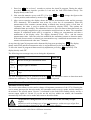
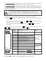
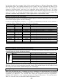
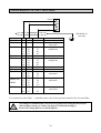
Operation Manual
CC28
Transmitter for flammable gases and vapours
GfG GESELLSCHAFT FÜR GERÄTEBAU MBH▐ KLÖNNESTRASSE 99▐ D-44143 DORTMUND▐ TELEPHONE +49 / (0) 2 31 / 5 64 00 –0 ▐ FAX +49 / (0) 2 31 / 51 63 13
[email protected] ▐ WWW.GASDETECTION.BIZ▐ AMTSGERICHT DORTMUND HR B 2742▐ CERTIFIED AS PER DIN EN ISO 9001:2000▐ ATEX QM CERTIFICATE
Content
Page
For your Safety
Operational Hints
General Description
Detection Principle
Design
Mounting Position of Transmitter
Mounting
Installation of Electrical Connections
Putting in Operation
Detection Mode
Check and AutoCal Adjustment of Zeropoint (ZERO)
Check and AutoCal Adjustment of Sensitivity (SPAN)
Service Menu and Extended Service Menu
Sensor Replacement
Transmission Characteristics
Special Status and relevant Error Messages
Messages in detection mode
Messages in service mode and during calibration
Situation of Status LED’s and Output
Priority of displays and messages in detection mode
Putting into Operation and Maintenance
Service, Inspection, Calibration and Adjustments
Regular Function Tests
Repair
Function Restrictions depending on Oxygen Concentration
Display Irritation due to Sensor Poisons
Trouble Shooting
Lower Explosion Limits (LEL) of Gases subject to Function Test
Spare Part List
Accessories
Connection Diagram CC 28 - with 4 .. 20 mA Output
Terminal Diagram MWG CC28
Sensor specification
Technical Data
Annex
Internal Memory CC28
EC-Type Examination Certificate
5
5
6
6
7
8
9
9
10
11
13
14
15
21
22
23
24
24
25
25
25
26
26
26
27
27
27
27
28
28
29
30
31
32
33
33
34
Warning:
The supply voltage must never exceed
30 V DC, not even in case of voltage peaks !
-4-
For your Safety
According to § 3 of the law about technical working media, this manual points out the proper use of
the product and serves to prevent dangers. It must be carefully read by all individuals who have or
will have the responsibility for operating, using, servicing, maintaining and controlling this product.
Like any piece of complex equipment, this product will do the job designed to do, only, if it is
operated, used, serviced, maintained and controlled in accordance with GfG’s instructions.
The warranties made by GfG Gesellschaft für Gerätebau with respect to the product are voided, if it
is not operated, used, serviced, maintained and controlled as per GfG’s instructions. The above does
not alter statements regarding GfG Gesellschaft für Gerätebau's warranties and conditions of sale and
delivery.
Operational Hints
According to the relevant national regulations, gas warning instruments have to pass a function test,
done by a specialist, after having been installed but before put in operation. For Germany,
§ 56(2) "UVV Gase" (BGV B6 - formerly VBG 61) is applicable.
Before shipment, the transmitter has passed a function and display test, being calibrated with suitable
test gases. This does not, however, overrule the obligation of putting in operation with test gas
after the installation.
The transmitter CC28 (including CC28 D and CC28 DA) is approved for the use in explosion
endangered areas and is subject to an EC-Type Examination Certificate issued by EXAM BBG Prüfund Zertifizier GmbH, according to directive 94/9/EG (ATEX100a) with the following
Certificate:
BVS 04 ATEX E 132 X
Labelling:
¯ II 2G EEx dem [ib] IIC T4
-20°C≤Ta≤+50°C
For the use in explosion endangered areas, with a measuring function for explosion protection, the
EXAM BBG Prüf- und Zertifizier GmbH issued an EC-type examination certificate for the transmitter
as per directive 94/9/EG.
Certificate:
BVS 05 ATEX G 001 X
The test was based on the standards DIN EN 61779-1 "Electrical apparatus for detection and
measurement of combustible gases – General requirements and test methods" and DIN EN 61779-4
"Electrical apparatus for detection and mesurement of combustible gases – Requirements for the
operational behaviour of apparatus of group II with a detection range up to 100 % of the Lower
Explosion Limit" and the DIN EN 50271 „Electrical devices for the detection and measurement of
combustible gases, toxic gases or oxygen – Requirements and testing for warning devices using
software and/or digital technology“.
!
The EC-Type Examination Certificate BVS 05 ATEX G 001 X
includes the following sensors, gases and detection ranges:
MK208-1, MK217-1, MK218-1 0 ... 100 %LEL CH4 (Methane), C3H8 (Propane)
0 ... 100 %LEL C2H4 (Ethylene), C3H8O (Isopropanol),
C3H6O (Aceton), C4H8O2 (Ethylacetate),
MK208-1, MK218-1
C6H14 (Hexane), C4H10O (Diethylether),
C9H20 (Nonane), C7H8 (Toluene)
0 ... 100 %LEL H2 (Hydrogen)
MK217-1, MK218-1
0 ... 4,00 %Vol. NH3 (Ammonia)
MK208-1, MK218-1
The functions marked (#) in this operation manual have not been part of the function and EC Type
Examination Certificate BVS 05 ATEX G 001 X.
-5-
General Description
A fixed gas monitoring system consists of a transmitter and a controller (GMA), which are connected
by means of cable. The transmitter converts the gas concentration into an electrical signal and
transmits it over the cable to the controller for further processing.
Compared to the transmitter CC28, the model CC28 D provides an additional display, while the
CC28 DA features a display and a visual and audible alarm.
The comprehensive electronics allow easy operation and maintenance and also increases the
operational safety and accuracy. The special features of the transmitter are:
•
•
•
•
•
•
•
Indication of concentration at display or at remote control
Adjustment by means of touch keys or remote control, without opening of casing
Compensation of temperature effects.
Ex-Approval for use at temperatures from -20 to +50°C
Function Approval for use at temperatures see sensor specification
Smart Sensor system – sensor replacement by means of plug-in, pre-calibrated sensor
Permanent status display (operation/fault) at transmitter
Detection Principle
The CC28 is operated on the detection principle "catalytic combustion" (fig. 1). The gas/vapour-air
mixture enters the sensor chamber by diffusion through the sinter filter. Inside the sensor chamber
there are an active and a passive sensor filament. The heated active sensor burns (oxidizes) the
entering gas at its vatalytic layer. This increases the temperature at the sensor and results in a change
of the electrical resistance, which is the measure for the gas concentration. The passive (reference)
sensor is exposed to the same ambient conditions as the active (detection) filament and is used for
compensation of environmental effects (e.g. temperature changes).
Detection principle - Catalytic combustion
Passive element
Sinter metal
Gas
Active element
Fig. 1
-6-
Sensor
chamber
Design
CC28 D
Cable gland
Detection range
Display
Touch keys
Type label with date of production
e.g. SN:0504xxxx (05=year, 04=month)
Status display
Buzzer
(only for CC28 DA)
green yellow
Operation Fault
Sensor casing
Potential equalization
Alarm LEDs
Key for quick adjustment
(AutoZero key)
behind lock screw
Connection for
Remote Control
CC28 DA
The type label shows the transmitter type. The sensor enclosure includes the sensor and the sensor
card, which carries the components for the sensor circuitry. For adjustment of electrical zeropoint and
sensitivity you can use either the built-in display or the remote control RC2. A secured key at the left
side of the transmitter allows a quick zero setting. The electronics on the main p.c.board converts the
sensor signal into a linear output signal of 4 .. 20 mA.
-7-
!
Always connect the remote control RC2 only for servicing a transmitter without
display.
The remote control RC2 may be used in explosion endangered areas.
They keys, functions and display of the
remote control RC2 are identical with
those of the transmitter.
Mounting Position of Transmitter
!
As per EN 50014 table 4 for devices of group II the casing has been tested with an
impact energy of 4 Joule (low degree of mechanical danger). Protect the casing
against very hard impacts.
It is essential to exactly know the ambient conditions, which have to be taken into consideration
before deciding on the mounting position. To achieve representative measurement results, take care
of
• the room ventilation and
• the gas density.
Install the transmitter at a place where the gases pass the sensor even in case of bad ventilation. If
necessary, use a smoke cartridge to check.
If the transmitter has to be installed at a position, where flow rates can be >3.0m/s, a wind protection
is necessary.
Generally a gas supply to the transmitter from below (sensor side) should be avoided.
Should the gas flow come from below, however, the displayed value may increased beyond the
tolerance as per EN61779-4.
Most combustible gases and vapours are subject to a higher density than air, the transmitter is to be
installed close to the floor. For lighter gases, with a lower density than air, the transmitter is being
mounted close to the ceiling. A few gases have a density which is similar to that of air. For these
gases the transmitter should be mounted at the breathing height of approx. 1.5 m over the floor. The
following chart shows the relative density of some gases and vapours. More detailed information is
available on request.
Gas/Vapour
relative gas density
Recommended
compared with air mounting position
Hydrogen, methane and ammonia
lighter
close to ceiling
Ethylene, ethane, acetylene, methanol
about same
at breathing height
Propane, butane, hexane, nonane, propanol,
heavier
close to floor
toluene, ethyl acetate, aceton, diethyl ether, all
other organic solvents and fuel mixtures
Furthermore, take the following into consideration as well:
•
•
Rain water, hose water, dripping water, condensate and
dust in the atmosphere.
-8-
The transmitter is to a great extent protected against the ingress of water and dust (IP 64). Special
accessories are available to provide additional protection for very difficult conditions. Please contact
GfG
for
detailed
information.
!
Warranty may be voided, if the sensor is exposed to ambient conditions which
were unknown to GfG during planning, production or delivery.
Mounting
When deciding on the position for the transmitter, make sure that it is always accessible for service
and maintenance. The transmitter must be mounted with the sensor showing to the floor.
For connecting the transmitter to the controller refer to the connection diagram (page 28). For
mounting the transmitter remove the four special screws and take the casing top off. Fix the casing by
means of two screws.
The printed circuit board inside the casing is potted in epoxy resin (encapsulation "m"). The sidemounted terminals (increased safety “e”) are used for connecting the controller.
Installation of Electrical Connections
Procurement of cable and electrical connections must be done by a specialist only, obeying the
applicable regulations. Always use shielded cable (e.g. LIYCY 3 x 1.5 mm2). The cross section of the
cable depends on the cable length. For short distances up to 200 m it may be sufficient to use
0.75 mm2 instead of 1.5 mm2. For longer distances the cross section must be 1.5 mm2. The cable
length must not be more than 1000 m.
The shield is fixed to the M16x1.5 screwing. In case the transmitter is mounted to an electrically
conductive background (e.g. steel grinder), a potential equalization is to be effected. If the transmitter
is installed in a room which is subject to Ex-regulations, make sure that only the transmitter is
installed in this area. The gas monitoring system resp. the mains supply and the controller must be
installed in the safe area.
!
The transmitter must be installed and opened in gas-free atmosphere only.
The transmitter must only be opened when de-energized.
Potential equalization
Terminal diagram
Pot. equalization min. 4 mm2
(at left side of casing)
e.g. steel
grinder
Cable gland
1
2
24V Ground
3
4
Transmitter
Type label
4..20mA
Buzzer
GMA Controller
Sensor
-9-
In case the transmitter is not operated on a GMA controller, the operational voltage of the mains unit
must not exceed 30 V DC.
Fix the casing top with the four special screws after installation.
!
The user must make sure that even in case of failure the voltage at the
transmitter terminals does not exceed the max. fault voltage Um indicated on
the type label.
Um = 250 V AC resp. Um = 45 V DC
Putting in Operation
The transmitter CC28 has passed quality control for correct operation and display before delivery.
The calibration was carried out with the appropriate test gases. Depending on transport, mounting
and ambient conditions however variations may occur. Therefore the gas warning system has to be
taken into operation and function checked by the manufacturer or by a professional which is
authorized by the manufacturer, according to BGV B6 (former VBG61-gases), resp. BG Chemie
guideline T 023.
After having been turned on, the unit needs a few minutes for:
• the self-test, checking the program and the working memory,
• entering and evaluating of transmitter parameters with simultaneous memory check,
• entering and evaluating of sensor parameters with simultaneous memory check,
• warming-up the sensor.
Within 6 seconds during the warm-up period the transmitter checks the memory first. The current
interface provides 0 mA and both the yellow and the green LED are lit. Then the output signal turns
to 1.6 mA, the fault LED lights up and the operation LED flashes slowly. The display reads LoAd,
then AdJ. Once this is completed, the display of the CC28 D and CC28 DA resp. of the remote
control RC2 at the CC28 reads the unit, the type of gas, the detection range, the alarm thresholds and
the calibration gas concentration one after the other. If the automatic reset of the ambiguity alarm is
activated, this is indicated last, and the fault LED flashes rapidly.
Once the warm-up is completed after 2 minutes, the CC28 turns to detection mode automatically.
During this period the display reads a countdown of the seconds from 120.
If a fault is recognized during this time, the transmiter turns to fault mode. The current interface
provides 1.2 mA and the display indicates a fault message (SYS ERR.). The status and fault LEDs are
lit constantly. The alarm LEDs and the display illumination will flash alternately.
Once the sensor has been replaced after a sensor fault (SENS ERR.), the transmitter is automatically
re-started. In case of sensor replacement adhere to the safety notes for electrical connections in
explosion endangered areas (see page 7).
Note:
After the initial putting into operation resp. after a sensor replacement it might be possible that the
value falls below or exceeds the detection range (____ resp. ----). In this case the zeropoint of the
transmitter must be corrected by starting the automatic zeropoint adjustment (ZERO).
Should SCAL ERR. occur (resettable), re-calibrate the sensor (SPAN) or, if necessary, enter the
service menu to adapt the detection range of the sensor to the hardware.
Allow a warm-up time of at least 30 minutes before you check the zeropoint. Once the warm-up is
completed, the display should read 0. Otherwise activate the (automatic) zeropoint adjustment
(AutoCal adjustment see page 11).
-10-
Detection Mode
In detection mode the display shows the current gas concentration.
The display reading is always identical with the display of the remote control connected!
The detection is provided by continuous monitoring. Exceeded thresholds (only for model CC28 DA)
and ambiguous sensor signals are recognized immediately and reported visually by the CC28.
Features of the electronics like parameter memory or sensor function are permanently monitored.
During trouble-free operation the green LED “ON“ is lit, the yellow fault LED is not lit.
To indicate that the CC28 is in detection mode the display alternates every minute to
unit and type of gas.
!
Falling Below Detection Range
Values below the zeropoint are indicated as figures with negative sign. Depending on the
measurement value the current interface provides outputs between 4.0 and 2.8 mA.
Deviations of the detection range by – 7.5% or more are indicated by the permanently lit fault LED
and the display reading ____ alternating with the negative value. The current interface provides a
permanent output of 2.8 mA.
Deviations of the detection range by – 7.5% or more are indicated by the permanently lit fault LED
and the display reads permanently ____.
In case of deviations beyond the detection range of the transmitter circuitry the current interface
provides an output of 1.2 mA.
Exceeding Detection Range
Detection ranges which are exceeded between 100 % and 112 % are indicated by ---- in the
display, alternating with the measured value. Depending on the measurement value the current
interface provides outputs between 20 and 22 mA.
Should 112 % be exceeded, the unit activates the ambiguity alarm. The display flashes ---- and the
current interface provides an output of 22 mA.
Touch Keys
The functions of the touch keys at the transmitter and at the remote control is identical. The same
applies to the display at the CC28 D, CC28 DA and the remote control.
Check of Display, LED and Buzzer
briefly in detection mode to activate the check of the display and LEDs. All LEDs are
Press
activated for 2 seconds, and all segments of the display (8.8.8.8) are shown. For the CC28 DA the
alarm LEDs and the buzzer are activated additionally.
TEST
ZERO
Display of Operational Parameters
During detection mode press key
briefly for the automatic indication of the following operational
parameters one after the other.
This order of readings will also appear after turning the transmitter on.
INFO
SPAN
Display / Example
1a
1b
2
3
4
5
6
7
LEL
UOL
CH4
SCAL 100
CL
MAS 80.0
A1 20.0
A2 40.0
AM
"b. oN
Meaning of display
Measuring unit (indication in % LEL)
Measuring unit (indication in Vol.%)
Type of gas
Detection range (full scale in “measuring unit”)
Calibration gas concentration (value in “measuring unit”)
Alarm threshold (value in “measuring unit”)
Alarm threshold (value in “measuring unit”)
Automatic reset of ambiguity alarm (display reading only,
if „on“)
-11-
Value in “measuring unit” means that the displayed figure stands for either % LEL or Vol.%. Reading in
Vol.% applies only to the gas ammonia.
Alarm Threshold (only for type CC28 DA)
The CC28 DA provides two alarm thresholds. An alarm is triggered, if the gas concentration exceeds
the preset limit value (adjustment in service menu). Exceeded thresholds are indicated by means of
the LED bar over the display, the display illumination and a buzzer. When the first threshold (A1) is
exceeded, the display illumination and the LED bar are alternating in low frequency. The display
reads the currect measurement value and A1 alternately.
Exceeding the second threshold (A2) activates the display illumination, the LED bar and the buzzer
alternating in high frequency. The display reads the current measurement value and A2 alternately.
Resetting the threshold alarms can be done automatically or manually, i.e. non-latching or latching
alarms, depending on the function setting in the service menu.
The function of the buzzer is fixed and cannot be changed: Activation by alarm 2, automatic reset
when the concentration has fallen below the second threshold, always resettable.
Pressing key
threshold.
QUIT
MENU
allows to reset a latching alarm, if the gas concentration has fallen below the alarm
Ambiguity Alarm
Due to the detection principle it might be possible that a very high gas concentration dissipates the
oxygen in the cell, thus resulting in a lack of oxidation and a reduced signal, although the sensor is
exposed to a gas concentration which is clearly above its detection range. For avoiding false signal
evaluation, the CC28 provides a warning from ambiguous sensor signals.
This alarm is triggered by exceeding of 112 % LEL and by recognition of a defined rise of signal
(Delta Alarm).
The ambiguity alarm is indicated by the fault LED flashing quickly. The CC28 DA additionally
activates the display illumination, the LED bar and the buzzer, alternating in high frequency. The
display also flashes ---- (also refer to Exceeding Detection Range).
On principal the ambiguity alarm is latching and can only be reset by pressing key
(or by
pressing the AutoZero key at models without display). The measurement value must be within the
detection range.
QUIT
MENU
!
The transmitter cannot recognize when the danger of an explosive gas
mixture resp. of an even higher gas concentration has ended. The end of a
gas hazard has to be checked with a portable detector which was already
turned on outside the hazardous area.
Should such an alarm be triggered by a high gas concentration, make sure to check ther zeropoint and
the sensitivity of the sensor, once the alarm was reset. Take into consideration that zeropoint and
sensitivity may vary considerably during the first few days.
Sensor Life
Catalytic combustion sensors are subject to a limited lifetime. The expected lifetime of the sensor
used in the CC28 for combustible gases is approx. 3 to 5 years, depending on operational conditions.
A few months before the lifetime expires, the transmitter indicates that the sensor has to be replaced
with the next service. The message is indicated by the fault LED flashing regularly and by the the
alternating reading of CHNL
M SENS and the measurement value. If the sensor is not being replaced
within the next few months, the transmitter turns off the detection mode, when the sensor is
exhausted. The current interface provides an output of 1.2 mA, the yellow fault LED lights up and
the green operational LED shortly flashes in intervals.
Fault
-12-
A fault of the transmitters is indicated by the constantly lit yellow fault LED, the current interface
provides 1.2 mA an error message is shown in the display (SYS ERR. or SENS ERR.).
Fault report is given, if:
• the sensor or the circuitry in the transmitter is defective;
• the sensor is missing;
• the self-test of the unit recognizes a failure.
For further causes see „Special Status and relevant Error Messages“ on page 21.
After the fault is cured, the yellow fault LED expires.
Check and AutoCal Adjustment of Zeropoint (ZERO)
A prerequisite for this check is atmospheric air without disturbing, resp. interfering gas components.
In polluted atmospheres you may alternatively use zero gas, which is free from combustible
components and interfering matters. Supply the zero gas to the sensor without pressure by means of
the flow adapter, at a flow rate of approx. 0.5 l/min.
Once the type of gas has been changed or the sensor has been replaced, the zeropoint must be
adjusted correctly. If the detection mode shows a deviation from 0 the zeropoint has to be corrected
as well. When the reading is constant the adjustment can be done using the AutoCal feature. The
AutoCal program automatically adjusts the zeropoint signal.
Conditions
The automatic zeropoint adjustment by means of the AutoZero key or with the standard access code
0011 is only possible, if the currently displayed value is max. 25 % LEL.
Expert users have the possibility to activate the zeropoint adjustment even for a display of 35 % LEL
by entering the access code 0055. This access code should only be used by trained safety personnel
of the customer.
Should the current zeropoint indication be higher than a value of 35 % LEL but it is for sure that this
value is not gas induced, the sub-menu info of the service menu indicates a temporarily valid (max.
1 hour) code (Code), which allows the activation of the zeropoint adjustment without any limitations.
Note:
If the last mentioned measure becomes necessary, this might be caused by a faulty sensor, which
should be replaced as soon as possible.
Execution
When the user presses the AutoZero key at a transmitter without display he cannot see whether the
measurement value is within the allowed tolerance band for zeroing (i.e. < 25 % LEL). Should the
measurement value be higher than 25 % LEL when the AutoZero key is pressed, the transmitter
remains in detection mode – to be identified by the fact that the fault LED is not lit. In this case the
zeropoint adjustment is only possible by means of the remote control.
For quick adjustment by means of the secured AutoZero key at the left side of the casing remove the
lock screw and press the key for at least 3 seconds. This switches the current output to 2.0 mA, the
fault LED flashes slowly, and step 3 below is started automatically.
When using the keypad at the display or at the remote control, follow the order below:
1. Press key
for at least 3 seconds to activate the program.
During the whole procedure the current interface provides 2.02 mA and the fault LED
flashes slowly.
The display shortly reads CodE.
2. Enter the numeric access code 0011 (resp. 0055). Use keys
and
to change the
figure at the current position, then confirm by means of key
.
TEST
ZERO
TEST
ZERO
QUIT
MENU
-13-
INFO
SPAN
3. After correct entering the display shows alternating the current measurement value and the
reading ZERo. When the measurement value remains constant for a defined time interval, the
display changes to read ZERo and ADJ for a few seconds, and the hardware internally
regulates its zeropoints. Once the regulation is completed successfully, the new zeropoint is
set, the AutoCal program is automatically terminated with the display reading SAUE, and the
transmitter returns to detection mode.
Notes:
If the current measurement value is beyond the allowed tolerances for the relevant access code, the
display reads fAi L shortly in step 3, and the transmitter returns to detection mode.
The AutoCal program can be shortened by long-term pressing key
or the AutoZero key, while the
measurement value is checked for constancy. Then the hardware starts to regulate/adjust the zeropoint
directly.
TEST
ZERO
For leaving the AutoCal program without zeropoint adjustment, press key
briefly. The display shortly reads ESC.
TEST
ZERO
or the AutoZero key
Once the quick adjustment is completed, remember to screw the lock screw
and its gasket in again to its stop!
!
The following error message may occur during zeropoint adjustment:
Display
Meaning
Fault LED
CAL
ERR.2
Gas signal is unstable.
CAL
ERR.3
Zeropoint is beyond the allowed tolerance
range.
flashing
quickly
All error message have to be confirmed with
or with the AutoZero key at the left side of the
casing. After confirmation the transmitter returns to detection mode without zeropoint adjustment.
QUIT
MENU
Check and AutoCal Adjustment of Sensitivity (SPAN)
For calibration of a transmitter without display you need the remote control RC2.
Press key
briefly to read the currently set calibration gas concentration as % LEL (for ammonia
as Vol.%) of the parameter (CL
MAS). The value of the test gas concentration should, if possible, be
20% above the main alarm threshold.
INFO
SPAN
!
Many combustible gases are also toxic. Handling toxic gases requires special
safety precautions.
TLVs give hints for hazards caused by toxic gases. For particularly toxic matters,
e.g. benzene or ethylene oxide, a reference gas is recommended for calibration.
For checking, resp. adjusting the display sensitivity (span) a calibration adapter has to be attached to
the sensor holder. Via this adapter the calibration gas can be supplied to the sensor at atmospheric
pressure with a flow of approx. 0.5 l/min., while the display has to be observed. Is there a deviation
between the displayed value and the actual calibration gas concentration a span calibration is
necessary. If the reading is constant the adjustment can be done using the AutoCal feature. The
AutoCal program automatically adjusts the measuring signal to the calibration gas. Follow the order
below:
→ Before a calibration is started, make sure that the sensor is free from calibration gas
(display 0).
-14-
1. Press key
for at least 3 seconds to activate the AutoCal program. During the whole
procedure the current interface provides 2.0 mA and, the fault LED flashes slowly. The
display shortly reads CodE.
and
to change the figure at the
2. Now enter the numeric access code 0011. Use keys
current position, and confirm by means of key
.
INFO
SPAN
TEST
ZERO
INFO
SPAN
QUIT
MENU
3. After correct entering, the display shows the current measurement value and the message
SPAN alternately. The transmitter now waits for a clear rise of concentration. When the
measurement value remains constant during a defined time interval (after a fixed time of
2 minutes), the value is used to update the sensitivity (display SAUE). This updates the
calibration data successfully. The transmitter, however, does not return to detection mode yet,
since the presently supplied test gas concentration would activate an alarm. The transmitter
remains in calibration mode until it recognizes a falling gas concentration and then a
stabilization of the display value. The display alternately reads ZERo and the current
measurement value. Once the value has stabilized, the transmitter returns to detection mode.
If the unit does not notice a reduced gas concentration resp. a stabilized measurement value, it
returns to detection mode after max. 3 minutes.
. The display
At any time the AutoCal program can be shortened by long-term pressing key
shortly reads SAUE and the measurement value is accepted directly as the sensitivity update.
To leave the AutoCal program without sensitivity adjustment, press key
only briefly. The
display shortly reads ESC.
INFO
SPAN
INFO
SPAN
The following error messages may occur during the adjustment:
Display
Meaning
Fault LED
CAL
ERR.1
No rise of test gas concentration noted.
CAL
ERR.2
Test gas signal is unstable.
CAL
ERR.3
Sensitivity is beyond the allowed tolerance
range.
flashing
quickly
The error messages have to be confirmed with key
. The transmitter returns to detection mode
without new calibration. The calibration procedure has to be repeated.
QUIT
MENU
Service Menu and Extended Service Menu
Activation of service menu
The service menu allows to select and to change all important parameters of the CC28. Entering the
service menu interrupts the detection mode; the transmitter turns to service mode, and the alarms are
de-activated. The special status "Service" is indicated by the fault LED flashing slowly and by a
current output signal of 2.4 mA. If you do not hit any key within one minute, the transmitter
automatically leaves the service mode and returns to detection mode.
!
All parameters changed in the service menu refer to the currently set type
of gas !
Should you wish to change type of gas and parameters, set the new type of gas first,
before parameter changes for this gas can become effective.
The service menu can be called in two different extensions.
-15-
The standard service menu is activated with code 1100 . It allows to adjust the calibration gas
concentration and, with model CC28 DA, all values which are related to alarms.
The extended service menu is activated with code 5050 . It allows to also change the type of gas,
full scale and ambiguity alarm. This code should only be used by specially trained safety personnel.
Activation of the extended service menu is only possible, if it has been authorized by GfG during the
basic setting of the transmitter.
For transmitters with function test (labelling BVS 05 ATEX G 001 X): The extended
service menu allows adjustments which may become the function test void !
If the full scale value of 100 % LEL is changed to a different value, or if the gas is
changed from a certified gas (see page 3) to a non-certified one, the function test becomes
invalid.
!
When using the keypad at the display or at the remote control follow the order below:
1. Press key
reads CodE.
QUIT
MENU
for at least 3 seconds. The transmitter turns to service mode. The display shortly
2. Enter the numeric code1100 (resp. 5050). Use keys
current position and confirm with key
.
TEST
ZERO
and
INFO
SPAN
to change the figure at the
QUIT
MENU
3. After correct entering the menu display reads L
MAS. Use keys
menu points.
TEST
ZERO
and
INFO
SPAN
to select the other
To activate a selected menu point press key
briefly. For parameter adjustment use keys
and
. For leaving the menu point briefly press key
again.
QUIT
MENU
TEST
QUIT
INFO
ZERO
SPAN
INFO
SPAN
Entry
menu point
TEST
ZERO
MENU
Display of
menu point
Description
iNFo
Indication of software version, serial number
and "Code" for ruling code
F2
Setting of alarm function 2
F1
Setting of alarm function 1
H2
Setting of hysteresis for alarm 2
H1
Setting of hysteresis for alarm 1
A2
Setting of alarm threshold 2
A1
Setting of alarm threshold 1
CL
MAS
Setting of calibration gas concentration
AM"B.
Setting of automatic reset for ambiguity alarm
SCAL
Setting of full scale deflection
L
MAS
Change of gas
SAUE
Leaving the service menu with storing of the
changed parameters
ESC
Leaving the service menu without storing of
the changed parameters
Menu point L
MAS – Change of type of gas (only possible in extended menu)
-16-
Remark
only visible and
changeable for
model CC28 DA
changeable only in
extended menu.
This function allows to select explicitly all parameters for different types of gas, which are stored in
the sensor. You can see only those gases which the sensor is scheduled for.
1. Activate of menu point L
MAS.
2. The display shows the presently set type of gas.
This reading can also be selscted in the standard service menu.
and
to set the gas.
3. Use keys
In the standard service menu the display shortly reads fAi L and then the presently set
type of gas (step 2).
TEST
INFO
ZERO
SPAN
4. Select the desired type of gas and confirm by pressing key
QUIT
MENU
briefly.
5. The CC28 is re-starting (RSET) (only for selection of a different gas).
If the type of gas has been changed several times before the user returns to a gas which was already
parameterized before, the transmitter takes over those parameters which were stored by the user
before.
If the type of gas has been changed and after a restart, the stored standard parameters (see table on
page 30) are taken over for a type of gas which is selected for the first time.
When the type of gas was changed, the zeropoint has to be adjusted in any case by means of the
AutoCal function. The sensitivity of the sensor for the new gas is to be checked as well and to be
adjusted by means of the AutoCal function, if necessary.
The different gases will be indicated either as shown in the list below.
Display
Gas
Display
Gas
Display
Gas
AcTN
Aceton
C7H8
Toluene
i.BvT
Iso-Butane
BvT.
n-Butane
CH4
Methane
M"EAc
Methyl acetate
BToL
Butanol
c.HEN
Cyclohexane
M"EoL
Methanol
BToN
2-Butanon
DEE.
Diethyl ether
M"iB.
MIBK
C2H2
Acetylene
DM"E.
Dimethyl ether
NH3
Ammonia
C2H4
Ethylene
EtAc
Ethyl acetate
non.
Nonane
C2H6
Ethane
EToL
Ethanol
Oct.
Octane
C3H4
Propine
H2
Hydrogen
PnT.
Pentane
C3H6
Propylene
HEN.
Hexane
ProL
2-Propanol
C3H8
Propane
HPt.
Heptane
YLoL
Xylene
C6H6
Benzene
Menu point SCAL – Adjustment of full scale deflection (only possible in extended menu)
The detection range can be set to 50, 75 or 100 % LEL. The detection range for ammonia (4 Vol.%)
cannot be changed.
Follow the 5 steps described below:
1. Activate menu point SCAL.
2. The display shows the presently set full scale value.
In the standard service menu the display reads "100" for 100 % LEL.
3. Use keys
TEST
ZERO
and
INFO
SPAN
for parameter adjustment.
-17-
In the standard service menu the display shortly reads fAi L and then the current value (step
2).
4. For leaving menu point SCAL press key
QUIT
MENU
briefly.
5. If necessary, store the parameter (SAUE).
Notes:
The EC-Type Examination Certificate BVS 05 ATEX G 001 X is only valid for a detection range
with a full scale of 100 % LEL resp. 4.00 %Vol. NH3.
If the full scale value is changed from 100 % LEL to a different value, the function test becomes
invalid.
The change of the detection range is mainly a change of the current output. The standardized output
signal of 4 – 20 mA is used for the new, reduced detection range. The display indication does not
change. A detection range of 0 – 50 % LEL results in the figures from 0 to 50.0 in the display (i.e. the
reading remains at % LEL).
Overrange and underrange refer to a percentage of the detection range, i.e. with a detection range of
0 – 50 % LEL the ambiguity alarm is triggered at approx. 56 % LEL ! Alarm thresholds are indicated
in % LEL (not in % of detection range) !
After a reduction of the detection range make sure that the alarm thresholds are checked and, if
necessary, corrected. If alarm thresholds were adjusted to a value beyond the new full scale
deflection, they are automatically set to the current full scale value.
Should the circuitry recognize that the currently set detection range cannot be monitored any longer
(sensor too sensitive for the measurement circuit, see also SCAL ERR.), the display turns
automatically to the highest possible value when entering this menu point.
Menu point AM"B. – Adjustment of the automatic reset of the ambiguity alarm (only possible in
extended menu)
1. Activate menu point AM"B.
2. The display reads the presently set status (oN or oFF).
This display can also be retrieved in the standard service menu.
3. Use keys
TEST
ZERO
and
INFO
SPAN
for setting the parameter.
In the standard service menu the display shortly reads fAi L and then the current status (step
2).
4. Press key
QUIT
MENU
briefly to leave menu point AM"B. .
5. If necessary, store the parameter (SAUE).
!
For the proper functioning of the automatic reset of the ambiguity alarm
the zeropoint adjustment of the CC28 must have been done correctly.
Notes:
This function is only active for the gases methane, propane and hydrogen. Should adjustment
AM"B. oN be selected, but none of the above gases is measured, the display order does not include the
reading AM"B. after pressing the info key.
The activation of the automatic reset is blocked until the next zeropoint adjustment, if the sensor has
been replaced or if the type of gas has been changed in the extended service menu !
As Info the display reads: AM
"B. -oN- instead of AM"B. oN.
-18-
The final reset is only enabled after a zeropoint adjustment has been done with the sensor plugged in.
Menu point CL
MAS – Adjustment of calibration gas concentration
The calibration gas concentration can be set within the range of 10 % – 105 % of the current
detection range, but never higher than 85 % LEL.
1. Use key
QUIT
MENU
to select menu point CL
MAS .
2. The display reads the currently set value for the calibration gas concentration in % LEL (for
ammonia in Vol.%).
3. Use keys
4. Press key
TEST
ZERO
QUIT
MENU
and
INFO
SPAN
to set the parameter.
briefly to leave menu point CL
MAS .
5. If necessary, store the parameter: Select menu point SAUE and confirm with
QUIT
MENU
.
Menu point A1, A2 – Adjustment of alarm thresholds (only visible at model CC28 DA)
The alarm thresholds can be set throughout the detection range; A1, however, cannot be set to a
higher value than A2. Setting a threshold to 0 de-activates the alarm. A2 can only be set to 0 when
A1 was also set to 0 before.
1. Activate menu point A1 resp. A2.
2. The display reads the presently set value for the alarm threshold.
3. Use keys
4. Press key
TEST
ZERO
QUIT
MENU
and
INFO
SPAN
to set the parameters .
briefly to leave menu point A1 resp. A2 .
5. If necessary, store the parameter (SAUE).
Notes:
The buzzer in model CC28 DA is always connected to alarm 2.
Menu point H1, H2 – Adjustment of hysteresis (only visible at model CC28 DA)
This function allows to adjust the hysteresis, i.e. the difference between activation and de-activation
of the alarm thresholds. The setting of the parameter is done in % LEL and is restricted to max. 5 %
LEL (for ammonia in Vol.%, max. 0.2 Vol.%).
Example:
At a CC28 with the detection range 0 .. 100 % LEL the hysteresis for alarm 1 was set to 4.0, i.e. the
alarm de-activation point for the alarm is 4 % LEL below the alarm threshold.
This results in the following alarm triggering:
Alarm 1
= 10 % LEL
Alarm activation
≥ 10 % LEL
3 % LEL
Hysteresis H1
Alarm de-activation
≤ 7 % LEL
1. Activate menu point H1 resp. H2.
2. The display reads the presently set value for the alarm hysteresis.
3. Use keys
4. Press key
TEST
ZERO
QUIT
MENU
and
INFO
SPAN
to set the parameter.
briefly to leave menu point H1 resp. H2 .
5. If necessary, store the parameter (SAUE).
-19-
Menu point F1, F2 – Adjustment of alarm functions (only visible at model CC28 DA)
1. Activate menu point F1 resp. F2.
2. The display reads the presently set code for the alarm function.
Display
NS
SC
3. Use keys
4. Press key
TEST
ZERO
QUIT
MENU
Alarm for exceeded threshold ...
non-storing (= non-latching), not resettable (# at alarm 2)
storing (= latching), resettable when fallen below
and
INFO
SPAN
for setting the parameter.
briefly to leave menu point F1 resp. F2 .
5. If necessary, store the parameter (SAUE).
Note:
The buzzer function at model CC28 DA is fixed to: „Alarm for exceeded threshold, non-latching,
resettable even during existing alarm conditions“.
The EC-Type Examination Certificate BVS 05 ATEX G 001 X is valid at alarm 2 only if set to
„S C“ storing (=latching).
Menu point iNFo – Indication of sensor type (MK number), sensor serial number, software
version, serial number and code
1. Activate menu point iNFo.
2. One after the other the display reads the MK number (S.typ xxx), the sensor serial number
(S.nr xxxx), the software version (SoFT xxxx), the 8-digit serial number of the transmitter in
2 parts (F.nr- xxxx F.nr_ xxxx) and a code (CoDE xxxx).
The figure indicated as CoDE is a (only temprorarily valid) code, which allows the activation of the
zeropoint adjustment without any limitations (refer to Check and AutoCal Adjustment of Zeropoint).
Menu point ESC – Leaving the service menu without storing
1.
1.
Select menu point ESC.
2.
Press key
changes.
QUIT
MENU
briefly to leave the service menu without storing of parameter
Menu point SAUE – Leaving the service menu with with storing
1. Select menu point SAUE.
2. Press key
QUIT
MENU
briefly to leave the service menu with storing of parameter changes.
Notes:
When the type of gas is changed, confirming the menu point activates the storing immediately and
enables the parameters for this type of gas.
Apart from this exception you can change several parameters one after the other without storing in between.
One collective storing procedure at the end of the settings saves all parameters which have been changed in
the service menu.
-20-
Sensor Replacement
The sensors MK 208-1, MK 217-1 and MK 218-1 are supplied with an EEPROM which stores the
sensor data (serial number etc.), the calibration data and the adjustable types of gases. The sensors are
fit to the transmitter by means of a plug connector.
For replacing the sensor unscrew the allen screw side-mounted at the impact protection (see picture
on page 5 sensor casing). Open the Transmitter casing and use suitable tool to push the sensor
downward. The new sensor slides in the casing from below; the sensor label must show forward. The
transmitter provides a lock against rotation, which makes sure that the sensor always fits properly.
Once the sensor is locked in place, secure it with the allen screw. When opening the casing take note
of the safety measures in Ex areas (see page 7).
Once the sensor has been removed, the yellow fault LED lights up and the current output signal falls
to 1.2 mA. At model CC28 D and DA the display reads SENS ERR.1 , and at the CC28 DA the alarm
LEDs flash slowly.
When the new sensor has been fit, the transmitter does an automatic re-start. The display reads RSET
and then TEST (memory test; current output signal of 0 mA). Then the warm-up period is started:
The display reads LoAd , the green LED flashes and the current interface provides an output signal of
1.6 mA. If all data of the new sensor match the stored data for the measurement task, the transmitter
turns automatically from warm-up to detection mode. Since the hardware zeropoints of the different
sensors resp. sensor types may differ considerably, a sensor replacement must always be followed by
a zeropoint adjustment ZERo (see page 11). There are no restrictions for the first zeropoint
adjustment after a sensor replacement. Zeroing is even possible at values far beyond the detection
range (____ resp. ----).
Possible error messages CHEC L
MAS or CHEC SCAL
CHEC L
MAS During the warm-up period the transmitter recognizes, if the new sensor is not specified
for the gas which is set as the measurement gas. The green LED turns from flashing slowly to a twin
flash (2 short flashes). The yellow fault LED remains lit, the current output still provides 1.6 mA, and
the display reads CHEC L
MAS . If the transmitter is to detect that gas which has been set, the sensor is
to be replaced by a cell which is suitable for this gas (e.g. sensor MK 217-1 by sensor MK 208-1).
Should you want to use the new, different sensor anyway (e.g. as a preliminary solution), you may
(longer than 3 seconds) in fault status and enter the acces code 5050 to enter the
press key
extended service menu (see page 14/15); menu point L
MAS (appears immediately after the code)
shows the types of gases the new sensor is specified for. If the user selects a type of gas and confirms
his choice by pressing key
, the transmitter is converted to this gas and re-started. Then the
zeropoint ZERo and the sensitivity SPAN have to be set for the new type of gas (see page 11-14).
QUIT
MENU
QUIT
MENU
CHEC SCAL New sensors, no matter for which gas, are always pre-set to the detection range of 0 –
100 % LEL. During the warm-up period the transmitter recognizes, if the detection range which was
set last, and the pre-setting of the sensor for the measurement gas do not match. The green LED turns
from flashing slowly to a twin flash (2 short flashes). The yellow fault LED remains lit, the current
interface still provides 1.6 mA, and the display reads CHEC SCAL . For check and, if required,
change of the detection range setting directly from the fault status, you may press key
(longer
than 3 seconds) and enter the code 1100 or 5050 to enter the service mode (see page 14/15), which
allows to do the adjustment under menu point SCAL. After leaving the menu with SAUE the warmup procedure is continued.
QUIT
MENU
Example:
If the detection range SCAL was set to 50 % or 75 %, a new and unused sensor will cause the display
to read CHEC SCAL .
-21-
If the transmitter is set to 100%, but the fit sensor had already been used in another unit which was
set to 50 % or 75 %, the display will also read CHEC SCAL .
Notes:
After the sensor was put into operation for the very first time, or when the sensor has been replaced,
the transmitter may indicate an overrange resp. underrange (____ resp. ----). In this case the
automatic zeropoint adjustment (ZERO) has to be activated to correct the zeropoint.
Should SCAL ERR. occur (resettable), the sensor must be re-calibrated (SPAN) or, if necessary, the
detection range of the sensor must be adapted to the hardware in the service menu.
Allow a warm-up time of at least 30 minutes before you check the zeropoint. Once the warm-up is
completed, the display should have stabilized to read 0. Otherwise activate the (automatic) zeropoint
adjustment (Adjustment see page 11).
!
Once the sensor was replaced (no matter which service and adjustment interval is
being considered), you have to effect a complete service and adjustment according to
DIN EN 50073 para. 6.4.3.
Check and adjustment of zeropoint and sensitivity is to be done as described (pages
11-14).
Transmission Characteristics
Depending on the type of gas the transmitter is subject to different transmission characteristics.
Different gases may show different response times. The transmission signal is always proportional to
the gas concentration
-22-
Special Status and relevant Error Messages
The table below describes those special status which cause the yellow fault LED to be lit
permanently. For a better diagnosis of a transmitter without display you should either read the error
messages below from the remote control RC2 or analyse the values from the current output.
green yellow
Output Cause
LED LED
No
Display
01
"TEST"
On
On
"Load"
flashing
On
02
Operational
para.
" AdJ "
03 Countdown flashing On
of seconds
Off
glows
10 "TEST"
0 mA
Action
Memory test when booting the system
1,6 mA Booting the system at start or after
change of gas (see page 8)
1,6 mA Sensor warm-up period
0 mA
Too low supply voltage
finishes automatically after 6
seconds
turns to sensor warm-up
automatically
finishes automatically after 120
seconds.
increase supply voltage
flashing
11
"CHNL
M"
"SENS"
flashing
shortly
(single
flash)
On
1,2 mA Sensor lifetime expired
Replace sensor
12
"CHEC"
"L
MAS "
Twin
flash
On
1,2 mA After sensor replacement:
Sensor is not specified for the gas
13
"CHEC"
"SCAL"
Twin
flash
On
14
" SYS "
"ERR.1"
" SYS "
"ERR.2"
" SYS "
"ERR.3"
" SYS "
"ERR.4"
" SYS "
"ERR.5"
Off
Off
On
1,2 mA After sensor replacement:
Detection range setting of sensor and
transmitter do not match for the gas
1,2 mA Fault during RAM access
Replace sensor again or
select different gas; see page 19
„Sensor Replacement“
Check and, if necessary, change
detection range SCAL
See page 19 „Sensor Replacement“
Re-start transmitter. If error is
reported again, replace transmitter
Off
On
1,2 mA Fault during ROM access
Off
On
Off
Off
" SYS "
"ERR.5"
Off
On
1,2 mA Fault during EEPROM access (internal) Re-start transmitter. If error is
reported again, replace transmitter
1,2 mA Reserved
Re-start transmitter. If error is
reported again, replace transmitter
1,2 mA Fault during regulation of sensor voltage
On
Off
On
"SENS"
"ERR.1"
Off
On
1,2 mA Sensor is missing
On
1,2 mA Fault during EEPROM access (sensor)
Off
On
1,2 mA Wrong sensor/parameter memory
Off
On
1,2 mA Error A/D converter (sensor voltage)
15
16
17
18
19
20
21
22
23
24
" SYS "
"ERR.7"
"SENS"
"ERR.1"
"SENS"
"ERR.2"
"SENS"
"ERR.3"
" ADv "
"ERR.1"
1,2 mA Fault during regulation of hardware
zeropoint
1,2 mA Temperature measurement is not
plausible
25
" ADv "
"ERR.2"
" ADv "
"ERR.2"
On
1,2 mA Error A/D converter (NTC)
26
" ADv "
"ERR.3"
Off
On
1,2 mA Error A/D converter (sensor current)
-23-
Re-start transmitter. If error is
reported again, replace transmitter
Re-start transmitter. If error is
reported again, replace transmitter
Fit sensor (automatic re-start)
Replace sensor (automatic restart)
Re-start transmitter.
If error is reported again, replace
transmitter.
Re-start transmitter.
If error is reported again, replace
transmitter.
Re-start transmitter.
If error is reported again, replace
transmitter.
Messages in detection mode
No Display
30 " ---- "
green yellow
Output
LED LED
Value
" ---- "
Value
On
flashing
quickly
22 mA
On
Off
20–22 mA Overrange
(between 100 % and 112 %)
On
Off
4–20 mA Gas concentration has reached resp.
exceeded the 2.alarm threshold.
Reduce gas concentration!
Latching alarm as standard.
On
Off
4–20 mA Gas concentration haa reached resp.
exceeded the 1.alarm threshold.
Reduce gas concentration!
Non-latching alarm as standard.
On
Off
4–20 mA Cautionary warning message:
Hardware/sensor combination cannot
recognize full scale deflection
alternating with
34
" A2 "
Value
alternating with
35
" A1 "
Value
alternating with
36
"SCAL"
" ERR."
Value
On
alternating with
37
38
39
"CHNL
M"
"SENS"
Value
flashing 4–20 mA Cautionary warning message:
shortly
End of sensor life within the next few
(single
months
flash)
Value
On
On
Off
Off
Value
On
On
On
On
2.8 mA
On
On
1.2 mA
alternating with
" ____ "
40 " ____ "
4–20 mA Normal detection mode
2.8–4 mA Detection range is deviated between
-7.5% and 0.0%
2.8 mA Detection range is deviated between
-8.0% and –25.0%
permanent
41 " ____ "
Caution Explosion hazards!
Latching alarm. Measures see page
9 and 10
Caution Explosion hazards!
Latching alarm. Measures see page
9 and 10
Caution Explosion hazards!
22 mA
alternating with
33
Gas concentration has exceeded
detection range of transmitter
electronics. Ambiguity alarm!
Overrange (> 112 %)
Ambiguity alarm!
flashing
quickly
flashing
32
Action
On
permanent
31 " ---- "
Cause
permanent
Detection range is deviated
< -25.0%
Measuring signal has fallen below
detection range of transmitter
electronics.
QUIT
Reset with
a) Re-calibrate sensor (SPAN)
b) Adapt resp. Reduce detection
range in service menu.
Replace sensor during next service
MENU
Adjust zeropoint
Adjust zeropoint and sensitivity
Adjust zeropoint and sensitivity
Messages in service mode and during calibration
42 Menu point
On
flashing
2.4 mA
43
"ZERo"
On
flashing
2.0 mA
44
"SPAn"
On
flashing
2.0 mA
45
" CAL "
"ERR.1"
On
flashing
quickly
2.0 mA
46
" CAL "
"ERR.2"
On
flashing
quickly
2.0 mA
47
" CAL "
"ERR.3"
On
flashing
quickly
2.0 mA
Service menu has been activated by
keys or by remote control RC2
Select menu point
Will return to detection mode
automatically, if no entry is
made within 1 minute
AutoCal-Adjustment of zeropoint in
Will be completed automatically
process (activated by key pad, RC2 or after successful adjustment
by AutoCal-Key)
Calibration activated by keys or RC2 Will be completed automatically
after successful adjustment
During AutoCal adjustment of
Reset with
sensitivity no rise of calibration gas
a) Check gas supply
concentration was recognized
b) Wait for request for adjustment before supplying gas
During AutoCal adjustment no stable
Reset with
zero gas resp. calibration gas
Stabilize gas supply
concentration was recognized
The zero point resp. the sensitivity is
Reset with
beyond the range of tolerance
a) Check zero resp. calibration gas
and repeat procedure.
b) Eventually replace sensor.
QUIT
MENU
QUIT
MENU
QUIT
MENU
-24-
In detection mode the messages listed in the second column are indicated alternating with the
measurement value. The readings described in No.33 and 34 are only applicable for model CC28
DA. The readings described in No.35 and 36 are cautionary warning messages. The transmitter
remains in detection mode, and there is no immediate action required by the user. The status
described in No.32 and 38 refer to a de facto extension of the detection range from 4–20 mA to the
range 2.8–22 mA, for showing measurement values „close“ to the original detection range. This
generates a tolerance range around the 4–20 mA signal, before a special status occurs.
Situation of Status LED’s and Output
The following table shows for a transmitter without display the different indications of the two status
LEDs and the output signals with their meanings.
For the zeropoint adjustment (if display > 25 % LEL), for adjustments to enter the service menu on a
transmitter without display the remote control RC2 is obligatory.
green LED
yellow LED
Output
On
On
On
On
On
On
On
On
On
On
On
flashing
Twin flash
Single flash
Off
On
On
On
flashing quickly
flashing quickly
Flashing slowly
Flashing slowly
Single flashes
Off
Off
Off
On
On
On
On
2,8 mA
1,2 mA
0 mA
22 mA
2,0 mA
2,4 mA
2,0 mA
4–20mA
20–22mA
4–20mA
2,8–4mA
1,6 mA
1,2 mA
1,2 mA
1,2 mA
Desription see chapter...
Page 21 „Messages in detection mode“ No.39, 40
P.21 „Messages in detection mode“
No.41
P.21 „Special Status and relevant Error Messages“ No.01
P.21 „Messages in detection mode“
No.30, 31
P.21 „Messages in service mode...“
No.45-47
P.21 „Messages in service mode...“
No.42
P.21 „Messages in service mode...“
No.43, 44
P.21 „Messages in detection mode“
No.36
P.21 „Messages in detection mode“
No.32
P.21 „Messages in detection mode“
No.(33, 34), 35, 37
P.21 „Messages in detection mode“
No.38
P.21 „Special Status and relevant Error Messages“ No.02, 03
P.21 „Special Status and relevant Error Messages“ No.12, 13
P.21 „Special Status and relevant Error Messages“ No.11
P.21 „Special Status and relevant Error Messages“ No.14-26
Priority of displays and messages in detection mode
The displays of situations with low priority will be substituted for displays with higher priorities (the
situations with low priority will not be deleted).
Priority
Situation
Description see chapter...
Ambiguity
A/D converter fault
(minor) overrange
Alarm2
Alarm1
Detection range deviation
„SCAL-Error“ (Warning)
Sensor Replacement (Warning)
Page 22 „Messages in detection mode“
P.21 „Special Status and relevant …“
P.22 „Messages in detection mode“
P.22 „Messages in detection mode“
P.22 „Messages in detection mode“
P.22 „Messages in detection mode“
P.22 „Messages in detection mode“
P.22 „Messages in detection mode“
No.30, 31
No.24-26
No.32
No.33
No.34
No.38-40
No.35
No.36
System- and sensor errors (P. 21, 22 No. 11 und No. 14-23) will interrupt the detection mode with its
messages. In case of a prior ambiguity alarm the status LEDs and the output will still indicate it and
the new special status will be indicated only by the LCD display.
Putting into Operation and Maintenance
Make sure that DIN EN 50073 „Guideline for choice, installation, use and maintenance of apparatus
for detection and measurement of combustible gases or oxygen“ as well as the relevant national
regulations are adhered to. For Germany this means the "Explosion Protection Regulations",
guideline T023 (BGI 518) „Gas warning Apparatus for Explosion Protection – Use and Operation“
and UVV-Gase BGV B6 „Accident Prevention Regulations Gases“.
-25-
After installation and during the initial putting into operation gas warning equipment have to be
checked for function by an expert (see DIN EN 50073 section 6.4.1)
Maintenance comprises inspection, service, calibration and adjustment as well as the regular function
tests and repair.
A function test has to be effected before putting the transmitter into operation and at least once a
year. This test comprises:
• Check with alarm gas concentration
• Check of zeropoint and sensitivity (calibration)
• Response time
• Gas sampling system, gas processing (if any)
• Alarm signal activation
• Messaging devices for malfunctions
The test must be carried out by a specialist. The result must be noted in a written test report.
Service, Inspection, Calibration and Adjustments
Inspection shouls include a visual check of the gas warning equipment (for Germany see guideline
T 023, chapter 8.1).
•
•
•
•
•
•
Mechanical damage
Soiling by dust
Condensate by moisture
Protective devices for transmitter
Diffusion inlet of transmitter
Gas sampling system, gas processing system (if existing)
Service and inspection comprise all measures which are necessary to keep the original proper
working condition of the gas warning system. The inspection intervals must not exceed 4 months.
•
•
•
•
•
•
Zeropoint
Sensitivity with calibration gas
Triggering of alarm thresholds
Response time
Messaging functions visually and audibly
Failure messages
Service and inspection include a regular check and adjustment of sensitivity and zeropoint. The
proper functioning of the system is to be checked as well.
It is recommended to entrust GfG service with this task.
Regular Function Tests
Depending on the ambient conditions gas warning systems may behave differently. It is important,
therefore, to do a daily visual check particularly during the first few days after the initial putting into
operation.
In addition to the maintenance work the function of the gas warning system has to be checked in
regular intervals. This interval must not exceed 1 year (for Germany see guideline T023, chapter 8.5
and UVV-Gase §56)
Checks are to be effected by an expert, and the result have to be confirmed in writing.
Repair
Repair comprises all repair and replacement work. It must only be done by the manufacturer and by
persons who are authorised by the manufacturer – i.e. by GfG Gesellschaft für Gerätebau mbH. Only
original spare parts and original assemblies are allowed to be used, which are tested and authorised
by the manufacturer.
-26-
Function Restrictions depending on Oxygen Concentration
Take note, that the measurement of gas and/or vapour concentrations in the range up to 100 % LEL
cannot be done accurately, if simultaneously the oxygen concentration is less than 10 Vol. %. In this
case the pellistor suffers from a lack of oxygen necessary for the „catalytic combustion“.
The Ex approval is not valid for using the transmitter in oxygen enriched atmospheres with
concentrations of more than 25 Vol.% oxygen.
Display Irritation due to Sensor Poisons
Certain parameters, known as "sensor or catalyst poisons", may affect the signal behaviour of the
sensor. The "sensitivity", i.e. the capability to emit signals, is being reduced. Sensor poisons are e.g.
sulphur, lead and silicon vapours. Usually these components are found very rarely or in very low
concentrations only.
Please draw your special attention to any interfering gases, which might be present at your detection
place and which might affect the proper functioning of your gas monitoring system. Depending on
the type of gas and its concentration, this affect may result in failures like a more or less steady, longterm loss of sensitivity or even to a sudden and considerable drop of sensitivity (see also
DIN EN 50073).
Trouble Shooting
Failure
Zeropoint cannot be adjusted
Sensitivity cannot be adjusted
Output current is fallen to 0 mA
Cause
Sensor is faulty
Sensor is faulty
Fuse is blown
Line is interrupted
Solution
Replace sensor
Replace sensor
Replace fuse
Re-connect
Lower Explosion Limits (LEL) of Gases subject to Function Test
Gas
Formula
Methane
Propane
Hexane
Nonane
Toluene
Aceton
Hydrogen
Ethylene
Diethyl ether
Ethyl acetate
Isopropanol
Ammonia
CH4
C3H8
C6H14
C9H20
C6H5-CH3
CH3-CO-CH3
H2
CH2=CH2
C2H5-O-C2H5
CH3-COO-C2H5
CH3-CHOH-CH3
NH3
LEL as per EN 61779
Function test
4.4 Vol%
1.7 Vol%
1.0 Vol%
0.7 Vol%
1.1 Vol%
2.5 Vol%
4.0 Vol%
2.3 Vol%
1.7 Vol%
2.2 Vol%
2.0 Vol%
15.0 Vol%
-27-
LEL as per data base
Chemsafe
4.4 Vol%
1.7 Vol%
1.0 Vol%
0.7 Vol%
1.2 Vol%
2.5 Vol%
4.0 Vol%
2.4 Vol%
1.7 Vol%
2.0 Vol%
2.0 Vol%
15.4 Vol%
Spare Part List
Cap and minor parts for 5 units
Casing top screws for 5 units
Casing bottom for CC28
Casing top with display for CC28 D and CC28 DA
Casing bottom without buzzer for CC28 and CC28 D
Casing bottom with buzzer for CC28 DA
Main module without alarm (Um=45V) for CC28 and CC28 D
Main module without alarm (Um=250V) for CC28 and CC28 D
Main module with alarm (Um=45V) for CC28 DA
Main module with alarm (Um=250V) for CC28 DA
Display module without alarm for CC28 D
Display module with alarm for CC28 DA
MK 208-1 Spare sensor for combustible gases
MK 217-1 Spare sensor for combustible gases
MK 218-1 Spare sensor for combustible gases
Part-No.
2800301
2800302
2800303
2800304
2800305
2800306
2800307
2800308
2800309
2800310
2800311
2800312
2800750
2800751
on request
Accessories
Remote control RC2
Part No.
2800201
Calibration adapter (flow rate 0.5 l/min ±0.1 l/min)
2800202
Wind protection
2800204
Wheather protective casing (#)
on request
Spare parts and accessories should be stored at an ambient temperature of 0 – 30°C. Storing time
should not exceed 5 years. For storage of spare sensors make sure that the ambient atmosphere is free
from aggressive media and sensor poisons.
-28-
Connection Diagram CC 28 - with 4 .. 20 mA Output
brown
green
white
1
2
3
4
Shield laid on
screwing
24 V GND
4 – 20mA
GMA101
GMA100
5
5
1
1
2
2
GMA104
55
58
61
64
5
55
58
61
64
28
1
19
22
25
19
22
25
28
19
:
40
53
56
59
62
1
53
56
59
62
29
2
20
23
26
20
23
26
29
20
:
41
54
57
60
63
2
54
57
60
63
30
3
21
24
27
21
24
27
30
21
:
42
GMA301
GMA304
GMA41
GMA81 (A)
GMA43
GMA44 and
GMA84
GMA88
with motherboard
from 1997
connection to
multiplexer
connection to
multiplexer
connection of up to 3
transmitters
connection of up to 4
transmitters
connection of up to 8
transmitters
For connection to the GMA … controller please refer to the operation manual of the relevant GMA.
!
According to EN 50014 table 4 for devices of group II the casing has been tested
with an impact energy of 4 Joule (low degree of mechanical danger).
Protect the casing against very hard impacts.
-29-
Terminal Diagram MWG CC28
3 – wire connection
1
U= 15.0 V - 30.0 V *
2
R1
CC28
3
I = 4 - 20 mA
4
Max. load 150 Ohm
4 – wire connection
1
U= 15.0 V - 30.0 V *
2
CC28
3
R1
I = 4 - 20 mA
4
Max. load 150 Ohm
*
DC (even short-term voltage peaks)
will blow the protective fuse.
A voltage exceeding the max. allowed value of 30 V
-30-
Sensor specification
MK208-1 Catalytic combustion sensor for combustible gases and vapors (according to EN 61779-4)
Response time
Flow rate
Pressure
Humidity
Temperature
Cross sensitivities
t50:
t90:
0...6m/s:
800...1100 hPa:
5%...90% r.F.:
-25...+55°C:
at 50%LEL:
at 2 %Vol NH3:
Special notes:
Expected lifetime:
≤ 5 s (CH4), ≤ 5 s (C3H8), *1
with wind protection: ≤ 8 s (CH4), ≤ 8 s (C3H8), *1
≤ 9 s (CH4), ≤10 s (C3H8), *1
with wind protection: ≤15 s (CH4), ≤17 s (C3H8), *1
max. ±3% of detection range or ±10% of display (regarding to 0 m/s) *2, *4
max. ±3% of detection range or ±7% of display (regarding to 1000 hPa) *4
max. ±5% of detection range or ±10% of display (regarding to 50% r.F. and 40°C) *4
max. ±5% of detection range or ±15% of display (regarding to 20°C) *4
Methane – Measuring range (#) *3
Propane – Measuring range *3
Nonane – Measuring range (#) *3 .
0,35 %Vol. C9H20:
= 100%
.
.
2,20 %Vol. CH4 :
0,85 %Vol. C3H8 :
2,00 %Vol. H2 :
= 100%
= 100%
ca.328%
ca.131%
ca.160%
2,00 %Vol. H2 :
2,00 %Vol. H2 :
1,25 %Vol. C3H6O: ca.231%
ca. 97%
ca.224%
1,25 %Vol. C3H6O:
1,25 %Vol. C3H6O: ca.111%
2,20 %Vol. CH4 :
ca. 96%
ca.107%
ca.213%
1,15 %Vol. C2H4 :
2,20 %Vol. CH4 :
1,15 %Vol. C2H4 :
ca. 96%
ca.101%
ca.210%
0,85 %Vol. C3H8 :
1,15 %Vol. C2H4 :
0,85 %Vol. C3H8 :
1,10 %Vol. C4H8O2: ca. 92%
1,10 %Vol. C4H8O2: ca. 95%
1,10 %Vol. C4H8O2: ca.201%
1,00 %Vol. C3H8O:
1,00 %Vol. C3H8O: ca. 93%
1,00 %Vol. C3H8O: ca.193%
ca. 87%
0,85 %Vol. C4H10O: ca. 87%
0,85 %Vol. C4H10O: ca. 87%
0,85 %Vol. C4H10O: ca.180%
ca. 74%
ca. 69%
ca.143%
0,50 %Vol. C6H14:
0,50 %Vol. C6H14:
0,50 %Vol. C6H14:
ca. 72%
ca. 67%
ca.132%
0,55 %Vol. C7H8:
0,55 %Vol. C7H8:
0,55 %Vol. C7H8:
ca. 57%
ca. 49%
ca.100%
0,35 %Vol. C9H20:
0,35 %Vol. C9H20:
2,00 %Vol. NH3:
ca. 57%
ca. 49%
2,00 %Vol. NH3:
2,00 %Vol. NH3:
This sensor is not suitable for the detection of hydrogen and for the use in hydrogenous areas. The sensor responds to
hydrogen, but is only suitable for warning of this gas. Permanent exposure to hydrogen may result in a permanently
rising signal.
5 years
MK217-1 Catalytic combustion sensor for combustible gases and vapors (according to EN 61779-4)
Response time
Flow rate
Pressure
Humidity
Temperature
Cross sensitivities
t50:
t90:
0...6m/s:
800...1100 hPa:
5%...90% r.F.:
-10...+40°C:
at 50%LEL:
Special notes:
Expected lifetime:
≤ 5 s (CH4), ≤ 7 s (C3H8), *1
with wind protection: ≤ 9 s (CH4), ≤ 9 s (C3H8), *1
≤10 s (CH4), ≤12 s (C3H8), *1
with wind protection: ≤18 s (CH4), ≤21 s (C3H8), *1
Max. ±3% of detection range or ±10% of display (regarding to 0 m/s) *2, *4
Max. ±3% of detection range or ±7% of display (regarding to 1000 hPa) *4
Max. ±5% of detection range or ±15% of display (regarding to 50% r.F. and 40°C) *4
Max. ±5% of detection range or ±15% of display (regarding to 20°C) *4
Methane – Measuring range (#) *3 . Propane – Measuring range *3 . Hydrogen – Measuring range (#) *3
2,20 %Vol. CH4 :
= 100%
0,85 %Vol. C3H8 :
= 100%
= 100%
2,00 %Vol. H2:
ca.115%
ca.188%
ca. 86%
2,00 %Vol. H2 :
2,00 %Vol. H2 :
2,20 %Vol. CH4 :
ca. 65%
ca.162%
ca. 53%
0,85 %Vol. C3H8 :
2,20 %Vol. CH4 :
0,85 %Vol. C3H8 :
When the sensor was exposed to a gas concentration which was considerably higher than 100%LEL, the zeropoint and
the sensitivity of the sensor have to be checked, once the gas concentration has disappeared.
5 years
MK218-1 Catalytic combustion sensor for combustible gases and vapors (according to EN 61779-4)
Response time
Flow rate
Pressure
Humidity
Temperature
Cross sensitivities
Special notes:
Expected lifetime:
t50:
t90:
0...6m/s:
800...1100 hPa:
5%...90% r.F.:
-10...+50°C:
≤ 5 s (CH4), ≤ 6 s (C3H8), *1
mit Windschutz: ≤ 8 s (CH4), ≤12 s (C3H8), *1
≤ 9 s (CH4), ≤12 s (C3H8), *1
mit Windschutz: ≤18 s (CH4), ≤25 s (C3H8), *1
Max. ±3% of detection range or ±10% of display (regarding to 0 m/s) *2, *4
Max. ±3% of detection range or ±7% of display (regarding to 1000 hPa) *4
Max. ±5% of detection range or ±15% of display (regarding to 50% r.F. and 40°C) *4
Max. ±5% of detection range or ±15% of display (regarding to 20°C) *4
Methane – Measuring range (#) *3 . Propane – Measuring range *3
. Nonane – Measuring range (#) *3 .
= 100%
0,85 %Vol. C3H8 :
= 100%
0,35 %Vol. C9H20:
= 100%
at 50%LEL: 2,20 %Vol. CH4 :
ca.121%
ca.195%
ca.333%
2,00 %Vol. H2 :
2,00 %Vol. H2 :
2,00 %Vol. H2 :
1,15 %Vol. C2H4 :
2,20 %Vol. CH4 :
2,20 %Vol. CH4 :
ca. 82%
ca.153%
ca.265%
0,85 %Vol. C3H8 :
1,15 %Vol. C2H4 :
1,15 %Vol. C2H4 :
ca. 69%
ca.120%
ca.223%
ca.182%
1,10 %Vol. C4H8O2: ca. 64%
1,10 %Vol. C4H8O2: ca. 91%
0,85 %Vol. C3H8 :
ca. 63%
1,00 %Vol. C3H8O:
1,00 %Vol. C3H8O: ca. 90%
1,10 %Vol. C4H8O2: ca.172%
0,85 %Vol. C4H10O: ca. 62%
0,85 %Vol. C4H10O: ca. 89%
1,00 %Vol. C3H8O: ca.170%
0,55 %Vol. C7H8:
0,55 %Vol. C7H8:
0,85 %Vol. C4H10O: ca.167%
ca. 58%
ca. 81%
1,25 %Vol. C3H6O:
1,25 %Vol. C3H6O: ca. 78%
0,55 %Vol. C7H8:
ca. 54%
ca.152%
ca. 52%
ca. 73%
0,50 %Vol. C6H14:
0,50 %Vol. C6H14:
1,25 %Vol. C3H6O: ca.146%
ca. 40%
ca. 55%
ca.137%
0,35 %Vol. C9H20:
0,35 %Vol. C9H20:
0,50 %Vol. C6H14:
at 2 %Vol NH3: 2,00 %Vol. NH3:
2,00 %Vol. NH3:
2,00 %Vol. NH3:
ca. 45%
ca. 60%
ca.113%
When the sensor was exposed to a gas concentration which was considerably higher than 100%LEL, the zeropoint and
the sensitivity of the sensor have to be checked, once the gas concentration has disappeared.
This sensor is not suitable for detection of aceton. The sensor responds to aceton, but is only suitable for warning of this
gas. Permanent exposure to aceton may result in a considerable loss of sensitivity.
5 years
*1 For other gases longer response times are valid, especially for nonane.
*2 At flow rates >3 m/s a wind protection is necessary. Generally it should be avoided that the
gas is supplied to the transmitter from below (sensor side).
*3 The cross sensitivities can vary depending on sensor and are dependent on gas concentration and
age of sensor. Other combustible gases which are not listed, are expected to cause an increase of
signal.
*4 This specification is valid for methane and propane.
-31-
Technical Data
3
Transmitter CC28
Transmitter type:
Sensor type:
Expected sensor life:
Gas:
Detection range:
Response time:
Alarm:
Detection principle:
Gas supply:
Supply voltage:
Max. supply current:
Max. fault voltage:
Output current:
CC28 ; CC28 D and CC28 DA
MK 208-1 ; MK 217-1 and MK 218-1
5 years - for normal industrial applications (see sensor specification)
Combustible gases and vapours,
e.g. Methane, Propane, Hexane, Nonane (see test report)
e.g. 0 .. 100 % LEL (see test report)
see sensor specification
only CC28 DA: visual and audible (90dB @ 10cm)
Catalytic combustion
Diffusion or
via flow adapter (flow rate 0.5±0.1 l/min)
15 .. 30 V DC
150 mA
250 V AC resp. 45 V DC (see type label)
4 .. 20 mA (max. load 150 Ohm)
Climate Conditions
Short-term storage temperature:
Recommended storage temperature:
Operational temperature (ambient):
-25 .. +60°C
0 .. +30°C
-20 .. +50°C for use in Ex-hazardous areas
-25 .. +55°C for use in non-Ex areas
see Sensor specification in case of using of MK217 or MK218
Humidity range: 5 .. 90% r.h.
Atm. Pressure range: 800 .. 1100 hPa
Flow rate: 0 to 6 m/s (>3 m/s with wind protection, mounting position see page 6)
Climate Effect as per EN 61779
Pressure
800 .. 1100 hPa
Humidity
20% .. 90% r.h.
Temperature
-25 .. +55°C
Flow rate 6 m/s
(1000 hPa)
(50%)
(20°C)
(0 m/s)
± 5% of range or ±30% of display
± 7% of range or ±15% of display
±10% of range or ±20% of display
± 5% of range or ±10% of display
Casing
Stability:
Casing material:
Dimensions:
Weight:
Protection:
Cable gland:
Cable type and length:
Protect the casing against very hard impacts (> 4 J)
anti-static compound
100 x 167.5 x 55 mm (WxHxD) (H with sensor: 193 mm)
approx. 800 g ( with display )
IP 64
screwing M16 x 1.5 max. cross section 3 x 1.5 mm2
LIYCY 3 x 0.75 mm2 for up to 200 m or
LIYCY 3 x 1.5 mm2 for up to 1000 m
Approvals and Certificates
Labelling:
Ignition protection classification:
EC-Type Examination Certification:
Function test:
EMC test:
¯ II 2G Y 0158
EEx dem [ib] IIC T4 -20°C≤Ta≤+50°C
BVS 04 ATEX E 132 X (electrical Ex-Protection)
BVS 05 ATEX G 001 X (measuring function)
EN 50270 : 1999
Radio shielding:
Type class I
Interference resistance: Type class II
-32-
Annex
Internal Memory CC28
Every transmitter is pre-programmed with the data of the most important gases and their additional
parameters. In most cases, therefore, the user does not need to change the configuration. The
following information is stored in the internal memory of the transmitter:
Gas
Formula
Unit
CGAS A1
(test gas)
Methane
Ethane
Propane
Butane
Pentane
Hexane
Heptane
Octane
Nonane
Iso-Butane
Cyclohexane
Ethylene (Ethene)
Propylene (Propene)
Acetylene (Ethine)
Propine
Hydrogen
Benzene
Toluene
Xylene
Methanol
Ethanol
Iso-Propanol (2-Propanol)
2-Butanol
Dimethyl ether
Diethyl ether
Aceton
2-Butanon (MEK)
Methyl acetate
Ethyl acetate
Methylisobutylketone
(MIBK)
Ammonia (0 – 4 Vol.%)
CH4
C2H6
C3H8
C4H10
C5H12
C6H14
C7H16
C8H18
C9H20
(CH3)3CH
C6H12
H2C=CH2
H2C=CH–CH3
HC≡CH
HC≡C–CH3
H2
C6H6
C6H5-CH3
C6H4-(CH3)2
CH3OH
C2H5OH
CH3-CHOH-CH3
CH3-CHOH-C2H5
CH3-O-CH3
C2H5-O-C2H5
CH3-CO-CH3
CH3-CO-C2H5
CH3-COO-CH3
CH3-COO-C2H5
CH3-COCH(CH3)3
NH3
A2
H1
H2
F1
F2
(Alarm 1) (Alarm 2) (Hyst. A1) (Hyst. A2) (Funct. A1) (Funct. A2)
%LEL
%LEL
%LEL
%LEL
%LEL
%LEL
%LEL
%LEL
%LEL
%LEL
%LEL
%LEL
%LEL
%LEL
%LEL
%LEL
%LEL
%LEL
%LEL
%LEL
%LEL
%LEL
%LEL
%LEL
%LEL
%LEL
%LEL
%LEL
%LEL
%LEL
45.5
50.0
50.0
50.0
50.0
50.0
50.0
50.0
50.0
50.0
50.0
50.0
50.0
50.0
50.0
50.0
50.0
50.0
50.0
50.0
50.0
50.0
50.0
50.0
50.0
50.0
50.0
50.0
50.0
50.0
20.0
20.0
20.0
20.0
20.0
20.0
20.0
20.0
20.0
20.0
20.0
20.0
20.0
20.0
20.0
20.0
20.0
20.0
20.0
20.0
20.0
20.0
20.0
20.0
20.0
20.0
20.0
20.0
20.0
20.0
40.0
40.0
40.0
40.0
40.0
40.0
40.0
40.0
40.0
40.0
40.0
40.0
40.0
40.0
40.0
40.0
40.0
40.0
40.0
40.0
40.0
40.0
40.0
40.0
40.0
40.0
40.0
40.0
40.0
40.0
1.0
1.0
1.0
1.0
1.0
1.0
1.0
1.0
1.0
1.0
1.0
1.0
1.0
1.0
1.0
1.0
1.0
1.0
1.0
1.0
1.0
1.0
1.0
1.0
1.0
1.0
1.0
1.0
1.0
1.0
1.0
1.0
1.0
1.0
1.0
1.0
1.0
1.0
1.0
1.0
1.0
1.0
1.0
1.0
1.0
1.0
1.0
1.0
1.0
1.0
1.0
1.0
1.0
1.0
1.0
1.0
1.0
1.0
1.0
1.0
NS
NS
NS
NS
NS
NS
NS
NS
NS
NS
NS
NS
NS
NS
NS
NS
NS
NS
NS
NS
NS
NS
NS
NS
NS
NS
NS
NS
NS
NS
SC
SC
SC
SC
SC
SC
SC
SC
SC
SC
SC
SC
SC
SC
SC
SC
SC
SC
SC
SC
SC
SC
SC
SC
SC
SC
SC
SC
SC
SC
Vol.%
3.0
1.0
3.0
0.1
0.1 NS
SC
If the transmitter is operated with a sensor for which no data are entered yet in this list, defined
settings are being used.
The user can adapt these settings individually and store them in the transmitter.
Worldwide Supplier of Gas
Detection Solutions
Firmware Version 2.4.1
197-000.12_OM.doc
GfG Gesellschaft für Gerätebau mbH
P.O.Box 440164, D-44390 Dortmund
Phone:
+49-(0)23156400 0
Fax:
+49-(0)231-516313
E-Mail: [email protected]
Internet: www.gasdetection.biz
Edition 04.04.2007
We reserve the right of modification
-33-
EC-Type Examination Certificate
-34-
-35-
-36-