1
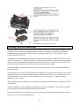
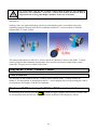
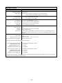
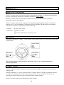
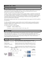
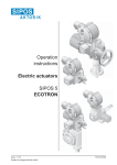
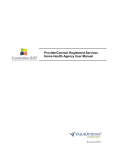
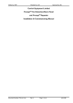
Worldwide Manufacturer of Gas Detection Solutions
IR 29 i/Di
Operation Manual
1194 Oak Valley Drive, Suite 20, Ann Arbor, MI 48108 ● 800-959-0573 ● 734-769-1888
Table of Contents
Page
For your safety
Operating instructions
General description
Measuring methods
Device design
Type plate with details of the transmitter version, serial number and ATEX certification
Site of installation for the transmitter
Assembly
Installing electrical connections
Using the RC 2 or RC 3 Remote Control
Commissioning
Measuring mode
Underrange
Overrange
Checking and AutoCal setting of the zero point (ZERO)
Checking and AutoCal setting of the sensitivity (SPAN)
Service menu and advanced service menu
Layout of the service menu
Displays and messages
Displaying special statuses and malfunctions
Fault messages of the main CPU
Fault messages of the sensor CPU
Displays in measuring mode
Displays in service mode and during adjustment (status messages)
States of the status LEDs and the current output
Displays and messages in measuring mode
Initial commissioning and servicing
Maintenance of fixed gas warning systems
Regular functional tests
Repairs
Parts and accessories
Connections and terminal assignment
Measuring gases and measuring ranges
Sensor specification
Internal parameter memory of the IR 29 transmitter
Technical data
Appendix RC 3
Application and purpose
Operation
Channel coding
Changing batteries
Technical Data
Appendix SB1 / SB1D
Operating instructions
Device design
Installing electrical connections
Technical data
2
2
3
3
4
4
5
5
6
8
9
10
10
10
13
15
16
18
21
21
22
23
24
24
26
26
27
27
27
27
28
29
31
31
33
34
36
36
36
36
37
37
38
38
38
38
40
For your safety
This user manual states the intended use of the product according to the manufacturer, GfG
Instrumentation, and intends to prevent accidents and work-related injuries. It must be read and
observed by all persons who operate, service, maintain and inspect this product. This product can
serve its intended purpose only if it is operated, serviced, maintained and inspected according to the
instructions given by GfG Instrumentation, Inc.
The warranty provided by GfG Instrumentation will become void if the product is not operated,
serviced, maintained and inspected in accordance with GfG’s instructions. The above does not
affect statements regarding warranties and liabilities in the company GfG's General Terms and
Conditions of Sale and Delivery.
Operating instructions
After installation but before commencing operation, gas warning systems must be inspected by an
expert to ensure they operate correctly and in accordance with national standards (commissioning).
The transmitter has been tested to ensure it is functioning correctly prior to delivery.
Calibration and adjustment took place with appropriate test or calibration gases.
This however does not release you from the obligation to commission the transmitter with test
or calibration gas after installation.
The IR 29 transmitter has been approved for application in potentially explosive atmospheres and
has an EC Type Examination Certificate issued by DEKRA EXAM GmbH in accordance with
Directive 94/9/EC.
Certificate: BVS 09 ATEX E 135 X
Certification:
!
II 1G Ex ia IIC T4 Ga -20°C≤Ta≤+55°C
CAUTION
The supply voltage should under no circumstances exceed 30 V DC! This also
applies to voltage peaks!
2
General description
A fixed gas warning system consists of a transmitter and a controller unit (GMA, not included). The
transmitter and the controller are interconnected by a shielded remote measurement cable. The
transmitter converts the gas concentration into an electrical measuring signal. The evaluation of the
measuring signal proportional to the existing gas concentration takes place at the controller (GMA).
The extensive electronics assumes various tasks which, on the one hand, facilitates operation and
maintenance and, on the other hand, significantly enhances operational safety and measuring
accuracy. The transmitter features the following:
• Concentration display on the display or remote control
• Settings without opening the housing with the RC 2 or RC 3 remote control
• Compensation of temperature influences
• Ex-protection in the temperature range -20 to +55 °C
• Functional test in the temperature range (see sensor specification)
• Permanent status display (operation / fault) at the transmitter
Measuring methods
The sensors installed in the IR 29 transmitter work according to the IR absorption principle.
Alignment to the gas type being monitored takes place using specific optical filters combined with
suitable characteristics. The reduced IR radiation at the detector is converted into an electrical
signal. This signal is amplified in the IR 29, filtered and used for the display or measured value
transfer. Due to its design with two radiation sources, the measurement assembly offers a powerful
signaling function and is less sensitive to interfering influences, such as deterioration of the
radiators or temperature deviations. Soiling of the optics can also be compensated up to a certain
degree. Due to the design and additionally available temperature and pressure compensation,
influence caused by ambient conditions is almost entirely eliminated.
The electronics of the IR 29 transmitter converts the measuring signal into a linear measured value
output 4...20 mA.
3
Device design
Diffusion
inlet
Gas inlet
Type plate with details of the transmitter version, serial number and
ATEX certification
4
Site of installation for the transmitter
When determining the site of installation, it is important to know the exact ambient conditions and
to take them into consideration. In order to receive representative results, the ventilation conditions
must be taken into account.
The position of the transmitter in the room must ensure that the gases still reach the sensor even in
the event of unfavorable ventilation. If necessary, carry out a measurement, e.g. with ventilation
smoke tubes.
When specifying the site of installation, it must be further observed that the transmitter can be
accessed for service and calibration tasks. The transmitter must be installed in a horizontal position,
with the measuring chamber on the left or right.
External influences must also be considered, such as:
• rainwater, splash water, dripping water, condensation
• the dust content in the atmosphere
The transmitter is protected against the ingress of water or dust to the greatest possible extent.
Special accessories can protect the transmitter against damage in extremely harsh measurement
conditions. If desired, GfG will gladly advise you about suitable measures.
!
The warranty may become void if the sensor is exposed to ambient conditions which
were unknown to GfG Instrumentation during the planning phase or delivery.
Assembly
Assembly takes place step-by-step in the following sequence:
5
Installing electrical connections
The installation of remote measurement cables and the connection of the electrical installation must
be carried out by a fully trained and qualified specialist in accordance with relevant regulations.
Installation must occur with a shielded cable (e.g. Helukabel OZ-BL-CY 4X1.5 mm2 or Lapp
Cables ÖLFLEX® EB CY).
According to the manufacturer, the cables must meet the requirements of DIN EN 60079-14 or IEC
60079-14 section 12.2.2. (VDE 0165 Part 1). Furthermore, the installed remote measurement cables
must be protected mechanically if both intrinsically safe circuits are conducted in one cable. This is
necessary to prevent the two intrinsically safe circuits coming into contact.
Suitable mechanical protection depends on the operating situation, the site of installation and the
hazard potential.
The conductor cross section is determined by the length of the connection line and the version of the
transmitter. Remote measurement cables with a conductor cross section of 0.75 mm2 can be used
for short distances of up to 500 m. The conductor cross section must be 1.5 mm2 for longer
distances of up to 1,000 m.
The shielding is fitted in the M16x1.5 cable gland. A ground connection may be required for the IR
29 transmitter.
Only the transmitter can be installed in a potentially explosive atmosphere – the controller and the
power supply unit must be installed outside this atmosphere.
If a ground connection of the housing is necessary, the ground connection terminal can be found at
the lower section of the mounting bracket.
6
!
The transmitter should only be installed when there is no gas present.
If the transmitter is not operated with the GMA controller, the operating voltage of the connected
power supply unit should not exceed 30 V DC even in the event of an error.
+
-
Mounting bracket
7
!
For service tasks, only the RC 2 remote control (BVS 04 ATEX E 212) should be
connected to the transmitter, or the RC 3 remote control (BVS 08 ATEX E 006) in
conjunction with an integrated display should be used at the transmitter.
The RC 2 remote control and the IR RC 3 remote control can be used in potentially explosive
atmospheres.
Settings of the zero point and display sensitivity (adjustment) can be executed directly at the
optionally integrated display at the IR 29 transmitter and the RC 3 remote control or with the
connected RC 2 remote control.
The buttons and functions of the RC 2 remote control are identical to those of the IR RC 3 remote
control. Output in the transmitter display takes place in plain text format; output in the remote
control RC 2 display occurs in abbreviated form.
Using the RC 2 or RC 3 Remote Control
Control buttons
The functions of the buttons at the RC 2 remote control and the IR RC 3 remote control are
identical. The designation of the buttons at the RC 3 can be displayed by briefly pressing the central
(oval) button at the display of the IR 29 transmitter.
Display and LED test using the RC 2 or RC 3 remote control
TEST
In measuring mode, briefly press the ZERO
button to trigger a display and LED test. All the LEDs
are subsequently activated for two seconds and all the segments of the display are shown.
8
Commissioning
The IR 29 transmitter is tested to ensure it is functioning correctly prior to delivery. Calibration and
adjustment takes place with a suitable test and calibration gas. Deviations may be identified
depending on the transport, assembly and ambient conditions.
Therefore, the gas warning system must be commissioned and tested by GfG Instrumentation to
ensure it functions correctly.
After switching it on, the gas warning system needs a few minutes to:
• carry out a self test during which the program and main memory are checked
• read and evaluate the device parameters with simultaneous memory check
• read and evaluate the sensor parameters with simultaneous memory check
• warm-up the sensor
The memory tests occur during the first few seconds of the switch-on phase. The current interface is
set to 1.2 mA, the orange and green status LEDs illuminate. During the second step, the current
interface is set to 1.6 mA, the fault LED illuminates and the operation LED flashes. The following
is initially shown on the display: Reading device param. / LOAD. The measuring unit, the type of
gas, the measuring range and the calibration gas concentration are subsequently shown one after the
other at the devices equipped with a display or at the RC 2 remote control.
The IR 29 transmitter switches to the warm-up phase of the sensor, the fault LED flashes and the
operation LED indicates readiness at 5 second intervals by flashing briefly – the remaining time is
shown on the display in seconds.
The measuring mode is automatically activated after the warm-up phase.
If a device error is detected during the start-up phase, the IR 29 transmitter switches to error mode.
The current interface is set to 1.2mA, an error message is shown on the display of the transmitter (if
available) or via the RC 2 remote control (see Displaying special statuses and malfunctions). The
fault LED is permanently lit. The display lighting additionally flashes with display versions.
Note:
Initial commissioning demands adjustment of the zero point (AutoCal ZERO) after the warm-up
phase and a subsequent sensitivity test, as well as possible adjustment (AutoCal SPAN).
9
Measuring mode
Measurement of the gas concentration occurs continuously. Functions of the electronics system,
such as parameter memory or the sensor function, are monitored permanently. In trouble-free
measuring mode, the green operation LED lights up, the orange fault LED is off.
The currently measured value is shown if the transmitter is equipped with a display.
The measured value display at a connected RC 2 remote control is identical.
When using an IR 29 without a display, the display of the RC 2 remote control changes from gas
concentration to gas unit and type of gas at one minute intervals.
When using an IR 29 with a graphical display, a pending measured value (>0) is shown as a bar
graph, which always displays the current measured value in addition to the numerical display (the
measuring gas and measuring unit are shown every 30 seconds instead of the bar graph). With
display "0.0", the measuring gas and measuring unit are always displayed instead of the bar graph.
Underrange
Measured values below the zero point are displayed as numerical values with a negative sign.
The current interface outputs a signal of between 2.8 mA and 3.9 mA according to the measured
value.
If the zero point deviation is too high, the current interface is permanently set to 2.8 mA, and
transmitters equipped with a display permanently show
and are referred to as underrange.
Overrange
Transmitters equipped with a display,
/ ---- and the measured value are alternately displayed
if the measuring range has been exceeded by up to 112.0 %. The current interface provides an
output signal of between 20...22 mA according to the measured value.
If the measured value exceeds 112.0 % of the measuring range,
/ ---- flashes on the display and
are referred to as overrange. The current interface is set to 22 mA.
10
Display of operating parameters (IR 29 with display)
INFO
During measuring mode, briefly press the SPAN Δ button at the RC 2 or RC 3 remote control to
automatically display the following important operating parameters one after the other:
1)
• Measuring gas 1
• Measuring unit 1
• Measuring range 1 (....)
• Calibration gas concentration 1 (.....)
2)
• Mean value of the last recorded 8 hours ( ... 2 )
• Mean value of the last recorded 15 minutes ( .... 3 )
1 These displays also appear during the switch-on phase
2 TWA (Time Weighted Average)
3 STEL (Short-Term Exposure Limit)
Here is an example of a display sequence for the RC 2 remote control with a 7-segment display on
an IR 29 i transmitter:
VOL H2 SCAL 4.0 CGAS 1.0 EUR 0.3 SEEL 0.1
Measured value histogram
When using a graphical display, it is possible to change to a different display mode. After triggering
INFO
INFO
the display of the operating parameters by pressing SPAN . Briefly press SPAN again to display
the histogram selection.
TEST
It is possible to view data of the last 2 hours, 8 hours or 24 hours (select by pressing the ZERO or
INFO
QUIT
button, press MENU to acknowledge your selection). The histogram display mode
SPAN
subsequently appears. It is possible to display average values, maximum values and minimum
TEST
INFO
values by (briefly) pressing the ZERO or SPAN button again.
Saved measured values are displayed in graphical form instead of the measured value. The currently
pending measured value is additionally shown in the top section together with the type of gas and
gas unit. The histogram is refreshed at regular intervals and can be used as a permanent display
mode.
Briefly press
QUIT
MENU
or appearing special messages to exit this display mode.
Sensor service life
The applied IR radiator has a limited service life. If the signal level falls below 85 % of the original
value, a display is activated stating that the optics must be checked for possible soiling at the latest
during the next maintenance period. The IR 29 transmitter must be replaced if it has become heavily
soiled or worn.
11
This is displayed by the regular brief flashing of the fault LED and by the display Device
replacement / CHNG IR 29 alternating with the measured value. If the signal level falls below 80
% of the original value, the transmitter switches off the measuring mode Sensor service life
exceeded / CHNG IR 29). The current interface is set to 1.2 mA, the orange fault LED illuminates
and the green operation LED
flashes at regular intervals
Device fault
If the transmitter is faulty, the fault LED (orange) lights up permanently, the current interface is set
to 1.2 mA and an error message appears on the display (see Displaying special statuses and
malfunctions).
A fault occurs, if:
• the sensor or the electronics in the transmitter is defective,
• errors occur during self monitoring of the device.
For further causes, please see Displaying special statuses and malfunctions.
The orange fault LED discontinues once the fault has been eliminated.
12
Checking and AutoCal setting of the zero point (ZERO)
Setting zero point must be performed in a fresh (clean) air environment or Synthetic air can also be
used if the atmosphere is contaminated.
The calibration adaptor must be used for checking and setting. Synthetic air can be applied
unpressurized by using the calibration adaptor with a flow rate of approximately 0.5 l/min.
If the zero point display deviates in measuring mode, a zero point offset is necessary. The zero point
also has to be reset after changing the measuring gas.
The AutoCal program ensures independent setting of the zero point signal under the conditions
specified above.
Activation
The zero point can only be set via the RC 2 or RC 3 remote control (only possible with IR 29
transmitter with a display).
Automatic zero point offset can only be executed after entering access code 0011 if the currently
displayed value is max. 10 % of the maximum measuring range.
An experienced user can activate the zero point setting after entering access code 0055 with a
display of up to 15 % of the maximum measuring range. This access code should only be used
by fully trained staff.
If the current zero point display exceeds a value of 15 % of the maximum measuring range and it
has been ensured that the display was not caused by the presence of gas, a temporary hour code
(valid for max. 1 hour) can be read in the Info / Info submenu of the service menu (Zero Code /
Code) and used to activate zero point setting without restrictions.
Note:
The necessity of the latter measure might be an indicator of a defective sensor and thus of the need
to replace the sensor as quickly as possible.
Adjustment
Adjustment takes place in three steps using the RC 3 and the IR 29 display or the RC 2 remote
control:
TEST
1. Press the ZERO button for a longer period (at least 3 seconds) to start activation. After activation,
the current interface supplies 2.0 mA throughout the entire process and the fault LED flashes at
slow intervals. The following appears on the display: Code / CODE.
2. The numerical access code 0011 or 0055 must be entered (this access code should only be used
TEST
INFO
by fully trained staff of the operator). Use the ZERO and SPAN buttons to change the number at the
QUIT
QUIT
current position and MENU to acknowledge the changes. Press the MENU button for a longer period
to delete the last acknowledged number.
If the entry was correct, the current measured value is shown on the display alternating with Zero /
ZERO. If the measured value remains constant during a defined time interval, a new zero point is
set. The AutoCal program is then automatically exited with Save / SAVE and returns to measuring
mode.
13
Note:
If the current measured value is outside the permissible limits for the respective access code, the
display Code incorrect / FAIL is shown briefly at Point 3 and the device returns to measuring
mode.
The AutoCal program can be shortened to a constant measured value by pressing the button for a
longer period (3 seconds) during the inspection. The hardware then begins zero point setting.
In order to cancel the AutoCal program without zero point setting during the waiting period, just
press the button or the AutoZero button briefly.
The following appears on the display: Cancel / ESC Press the button to acknowledge it.
The following error messages can occur when setting the zero point:
QUIT
All error messages must be acknowledged with MENU . After acknowledgement with the unchanged
zero point setting, the transmitter returns to measuring mode.
14
Checking and AutoCal setting of the sensitivity (SPAN)
The RC 2 or RC 3 remote control is required for devices without a display in order to carry out
calibration and adjustments.
Initially, check the set calibration gas concentration by pressing briefly. The value of the calibration
gas concentration must be at least 20 % of the measuring range.
!
Always observe special safety precautions when handling toxic gases. MAC values
indicate hazards caused by toxic gases.
Use the IR 29 calibration adaptor to check and adjust the sensitivity of the display. The calibration
gas is fed unpressurised through the gas inlet with a volume flow of approx. 0.5 l/min. The gas
concentration can be checked directly on site on the RC 2 display. If the display deviates from the
calibration gas concentration, the sensitivity must be set.
The sensor must be free from calibration gas (reading zero) prior to each re-adjustment.
Adjustment takes place in four steps using the RC 3 and the IR 29 display or the RC 2 remote
control:
1. Press the button for a longer period (at least 3 seconds) to start activation. After activation, the
current interface supplies 2.0 mA throughout the entire process and the fault LED flashes at slow
intervals. The following appears on the display: Code / CODE 2. The numerical access code 0011
or 0055 must be entered (this access code should only be used by fully trained staff of the
operator). Use the and buttons to change the number at the current position and to acknowledge the
changes. Press the button for a longer period to delete the last acknowledged number.
3. After correct entry, the expected calibration gas concentration is shown on the display. This must
be set to the value of the calibration gas (printed on the cylinder) and acknowledged (proceed as
described under 2).
4. The current measured value and Span / SPAN are shown alternately on the display. The device
subsequently waits for a noticeable increase in the concentration. If the measured value remains
constant during a defined time interval (after a fixed waiting period of 2 min.), the measured value
is accepted for refreshing the sensitivity (display Save / SAVE). The adjustment data has then been
saved successfully.
5. However, the transmitter does not yet return to measuring mode, as a still pending concentration
of calibration gas could trigger alarms. The transmitter remains in adjustment mode until there is a
decrease in the gas concentration and stabilization of the display value is subsequently detected.
Meanwhile, Zero / ZERO is shown on the display alternating with the current measured value. The
device returns to measuring mode after stabilization. If no gas decrease and stabilization of the
measured value is detected, the device automatically returns to measuring mode after 3 minutes.
Note:
The AutoCal program can be shortened in each phase by pressing the button for a longer period.
Save / SAVE appears briefly on the display and the measured value is accepted directly to refresh
the sensitivity.
15
Only press the button briefly to cancel the AutoCal program without setting the sensitivity. Cancel /
QUIT
ESC appears on the display and must be acknowledged by pressing the MENU button. Subsequently,
it is returned to measuring mode as described under 5.
The following error messages can occur when setting the sensitivity:
QUIT
Acknowledge the error messages with MENU . The transmitter changes to measuring mode without
re-adjustment, the data of the last valid calibration is used, and the adjustment must be repeated.
Service menu and advanced service menu
Activate the service menu
All important parameters of the IR 29 transmitter can be opened and changed in the service menu.
The measuring mode is interrupted when opening the service menu and the device changes to
service mode. The special status "Service" is indicated by the slow flashing fault LED and the
output signal is set to 2.4 mA. If the user does not press any button, the device automatically exits
the service mode after one minute and returns to measuring mode.
All parameter changes carried out in the service menu relate to the currently set type of gas!
If the type of gas and parameters are to be changed, the new type of gas must be set first before
parameter changes can become effective for this type of gas.
Two service menu versions are available.
The standard service menu is opened with access code 0011 It is not possible to change important
settings, such as measuring gas or measuring range end value, here. Such attempts are ignored and
the message Locked / FAIL appears.
The advanced service menu is opened with access code 5050 All settings can be carried out
without restrictions in the advanced service menu. This access code should only be used by
specifically trained staff of the operator.
Execution takes place in three steps using the RC 3 and the IR 29 display or the RC 2 remote
control:
QUIT
1. Press the MENU button for at least 3 sec. The transmitter changes to service mode. The following
appears on the display: Code / CODE
16
TEST
INFO
2. Now enter the numerical access code 1100 or 5050 Use the ZERO and SPAN buttons to
QUIT
change the number at the current position and MENU to acknowledge the changes. Press the
QUIT
MENU button for a longer period to delete the last acknowledged number.
3. After correct entry, the service menu opens with menu item Gas / GAS. Use the
INFO
buttons to select other menu items.
SPAN
TEST
ZERO
and
Operation
A menu item is selected using the
After selection, briefly press the
parameter.
TEST
ZERO
QUIT
MENU
and
INFO
SPAN
buttons.
button to activate a desired menu item or to select a
The service menu can be exited with or without saving the changed parameters.
Note:
It is possible to change several parameters one after the other without having to save the changes
individually. All the parameters previously changed in the submenus are saved when exiting the
service menu through the menu item save.
Exceptions:
1) Changing the type of gas – if a different type of gas is selected in the "Gas" menu, it is saved
immediately, the parameters for this type of gas are activated and the IR 29 transmitterr restarts with
the changed parameters.
2) When setting the time and date, they are saved immediately.
Some parameters are related to each other. Therefore, other parameters might be adjusted
automatically after changing a parameter.
17
Layout of the service menu
18
Additional menu explanations
Cancel
Exit the service menu without saving the parameters, changes are discarded.
Save
Exit the service menu with saving all the changes to the parameters.
Gas
The gas type and the parameters stored in the sensor can be selected using this function. Only gases
are displayed for which the sensor is intended and for which it has been programmed.
Note:
If a changeover to a different type of gas occurs, the IR 29 transmitter will restart. Changing to a
new type of gas always requires an adjustment of the zero point (AutoCal ZERO) after its warm-up
time and subsequently a sensitivity check, and, if necessary, an adjustment (AutoCal SPAN).
There are no restrictions for the first zero point setting after a gas change.
After a gas changeover, parameters, such as the measuring range and the calibration gas
concentration, must be checked and, if necessary, adjusted.
Measuring range
The measuring range end value can be set in steps to 10.0, 15.0, 20.0, 25.0, 30.0, 40.0, 50.0, 75.0,
100.0 % of the maximum measuring range, but not smaller than 1/6 of the maximum measuring
range end value.
Note:
Changing the measuring range is predominantly an adjustment of the output signal. The
standardized output signal 4...20 mA is used for the new measuring range. The numerical display
does not change.
Cal. Gas
A default value is pre-set as the calibration gas concentration. This value must be compared to the
value set on the test gas cylinder and, if necessary, adjusted.
Zero band
The zero band of the sensor can, if required, be deactivated, the true measured value is also
displayed around the zero point.
Possible settings:
• Zero band activated (On / On)
• Zero band activated (Off / Off)
Info
Retrievable/Displayed device information:
• Sensor type/MK number (sensor type / S.TYP)
• Sensor serial number (sensor no. / S.NR)
• Software version (software ver. / S.NR)
• Transmitter serial number (serial no. / F.NR-F.Nr)
• Hour code (ZERO Code / CODE)
19
Note:
The number shown under ZERO Code / CODE is an access code that is valid for a limited period of
time and can be used to activate the zero point setting without restrictions (see AutoCal ZERO).
INFO
With a RC 2 remote control connected, the individual displays must be shifted by pressing SPAN .
Language/Time/Bus
Language
Possible language settings:
• German (Deutsch / ...)
• English (English / ....)
• Spanish (Espanol / ...)
Note:
The language setting generally influences the presentation on the graphical display.
Language/Time/Bus Time
Setting sequence: Year, month, day, hour, minute
20
Displays and messages
Displaying special statuses and malfunctions
The following table lists the special statuses for which the orange fault LED is permanently
illuminated and the current interface is set to =1.6 mA. When using a IR 29 transmitter without a
display, the following error messages should be displayed with the RC 2 remote control for
improved diagnosis or the exact value of the output signal analyzed.
21
Fault messages of the main CPU
22
Fault messages of the sensor CPU
23
Displays in measuring mode
Notes:
In measuring mode, the messages listed in the second column are shown alternating with the
measured value. The display described under No. 207 represents a precautionary warning message.
The transmitter remains in measuring mode and the operator does not need to react immediately.
The statuses described under No. 203 and No. 210 refer to the extension of the evaluation of the
output signal 4...20 mA to 2.8...22 mA in order to display deviations while taking into account the
tolerances in the default measuring range.
Displays in service mode and during adjustment (status messages)
24
25
States of the status LEDs and the current output
For improved clarity, the following table shows the various displays of both status LEDs and the
current output signals as well as their meaning for a IR 29 transmitter without a display.
The RC 2 remote control is mandatory for a device without a display in order to offset the zero
point, to carry out adjustments and to call the service menu.
Displays and messages in measuring mode
The displays of the various messages take place with different frequencies of occurrence according
to their influence on the measuring process.
The table gives an overview of which messages influence the measuring mode.
Fault messages (system and sensor errors No. 101 and No. 104-125) terminate the measuring mode
until they have been eliminated. They are shown permanently on the display and are additionally
output via the LED code specified above (also with version without a display).
Warning messages allow the continuation of the measuring mode, but might have to be
acknowledged or are self-acknowledging. They are displayed alternating with the measured value. If
there are several warning messages pending, they are displayed cyclically.
Example:
Warning messages 207 and 213 are pending. These messages are output on the display in the
following sequence:
....measured value...message 207....measured value....message 213....measured value....message
207....etc.
Status messages are special messages which are triggered by special functions and interrupt the
measuring mode. All these messages and statuses are self-resetting after a certain period of time.
The transmitter then re-assumes the measuring mode independently.
26
Initial commissioning and servicing
DIN EN 60079-29-2 "Gas detectors – Selection, installation, use and maintenance of detectors for
flammable gases and oxygen" as well as the relevant national rules and regulations must be
observed. During initial start-up, gas warning systems must be checked for proper functioning by an
expert after installation. (see DIN EN 60079-29-2 section 8.9 and data sheet BGI 518 / T023 section
8.1). Servicing includes inspection, maintenance, calibration and adjustment, as well as regular
functional tests and repairs. Tests must be carried out by an expert and written confirmation of the
result must be provided.
Maintenance of fixed gas warning systems
The maintenance of fixed gas warning systems includes:
Monthly visual inspections to check for:
• Mechanical damage
• Dust contamination
• Condensation due to moisture
• Safety equipment for transmitters
• Diffusion openings of the transmitters
• Gas extraction system, gas treatment (if available)
Functional check, Interval: 4 months
Scope of the functional checks:
• Calibrations (measured value display) using zero and calibration gas
• Adjustment of the zero point and sensitivity setting using zero or calibration gas
• Triggering alarm thresholds
• Setting time
• Output functions, optical and acoustic
• Fault messages
System checks (section 9.3), Interval: 1 year
It is recommended to contact Customer Service for maintenance.
Regular functional tests
Tests must be carried out by an expert and written confirmation of the result must be provided.
Repairs
This includes all repair and replacement parts. Only use original spare parts and original modules
inspected and approved by the manufacturer.
27
Parts and accessories
1.
2.
3.
4.
5.
6.
7.
Description
Part Number
Double safety barrier (Type: SB1), two channel, for IR 29 integrated in a wall
2910210
mounting case (IP65)
Diffusion cover for adjusting IR 29, material: viton
2910220
RC3 - Remote control, infrared remote control for IR 29
2910230
RC2 - Remote control, Required for calibration of blind transmitters; option for
2800201
transmitters with display. Includes 6-foot connection cable.
Connection cable for RC2 Remote Control. 6 feet
2800210
Connection cable for RC2 Remote Control. 16 feet
2800211
Connection cable for RC2 Remote Control. 33 feet
2800213
28
Connections and terminal assignment
IR 29 with 4..20 mA interface and Zener barriers
IR 29 i with 4..20 mA interface and SB1
29
IR 29 i with 4..20 mA interface and 3-wire cable (e.g. GMA41)
!
CAUTION!
Cabling must take place with strands to establish the required bridge X1-X3. Both
conductors in X1 must be inserted correctly into a common, sufficiently dimensioned
wire and ferrule.
The application of different conductors (solid wire and strand) is not permitted!
The application of several solid wires in one wire end ferrule is not permitted!
30
Measuring gases and measuring ranges
Sensor specification
31
32
Internal parameter memory of the IR 29 transmitter
Each IR 29 transmitter is preprogrammed with the data of the most important gases and their
additional parameters. Therefore, users should not find it necessary to change the configuration. The
following information is stored in the internal memory of the transmitter:
33
Technical data
Device types
Measuring function
Measuring method:
Output signal:
Power supply
Voltage supply:
Voltage supply SB1:
Climatic conditions
For storage:
For operation:
Air pressure:
Humidity:
Housing
Protection class:
Material:
Weight:
Dimensions:
Approvals and inspections
Certification:
Ignition protection class:
EC Type Examination Certificate:
IR 29 i and IR 29 Di
IR absorption
4..20 mA (max. resistance: 340 Ω @ 15 V or 740 Ω @ 24 V)
(max. resistance at GfG SB1: 270 Ω @ 22 V-30 V))
15..30 V DC @intrinsically safe supply
22..30 V DC @supply via GfG SB1
-25..+60 °C (recommended 0...+30 °C)
-20..+55 °C (also see sensor specification)
0..200 kPa (also see sensor specification)
0..100 % RH (non-condensing)
IP67
Stainless steel, polycarbonate, PA, POM
approximately 950 g
6.3386 inches x 2.9528 inches / 161 mm x 75 mm (L x 0); mounting surface at
least 6.3386 inches x 5.2362 inches / 161 mm x 133 mm; Height 4.6457 inches /
118 mm
II 1G 0158
Ex ia IIC T4 Ga -20 °C≤ Ta ≤+55 °C
BVS 09 ATEX E 135 X
Electrical parameters for the intrinsically safe connection
Intrinsically safe supply circuit:
Maximum input voltage:
Maximum internal capacity:
Maximum internal inductance:
Connection via terminals X1 and X2
Ui DC 30 V
Ci 11 nF
Li negligible
Intrinsically safe signal circuit:
Maximum input voltage:
Maximum internal capacity:
Maximum internal inductance:
Connection via terminals X3 and X4
Ui DC 30 V
Ci 1.8 nF
Li negligible
The intrinsically safe signal circuit is galvanically separated from the intrinsically safe supply circuit up to a sum of the
maximum values of the nominal voltage of 60 V.
34
35
Appendix RC 3
Application and purpose
The RC 3 remote control can only be used for operating and checking, or calibrating and adjusting
the zero point and the sensitivity of the IR 29 transmitters with a display.
The RC 3 remote control is powered by a lithium battery, which should not be replaced in
potentially explosive atmospheres.
The RC 3 remote control has been approved for application in potentially explosive atmospheres
and has an EC Type Examination Certification issued by DEKRA EXAM GmbH, in accordance
with Directive 94/9/EC (ATEX100a) with the following
Certificate:
Certification:
BVS 08 ATEX E 006
I M1 Ex ia I Ma
II 1G Ex ia IIC T6 Ga -20°C≤Ta≤+55°C
Operation
The button assignment of the RC 3 can be shown on the display of the device by briefly pressing the
central button.
The receiver software only responds to activations >0.6 sec. to avoid unintentional or
incorrect operation.
Channel coding
The RC 3 has been coded to channel 16 from the factory. Each IR 29 transmitter can be operated
with this code.
If desired, channels 1-15 can be coded in the RC 3 from the factory. The IR 29 transmitter must be
set to the same channel. This can be carried out by the user and is reversible. This ensures the
grouping of devices which can only be operated with a separate channel.
The RC 2 remote control is not influenced by these settings.
36
Changing batteries
!
The Caution!
Never open the device in potentially explosive atmospheres to change the lithium
battery.
When inserting the new lithium batteries, always observe their polarity. These batteries should only
be obtained from the manufacturer, GfG Instrumentation. Internal monitoring ensures that only
batteries which meet the demands of the Type Examination are used. The battery type is: VARTA
CR 2430.
Technical data
Type designation
Climatic conditions
RC 3
For operation:
Power supply
Housing
-20..+55 °C | 5..95 % RH | 700..1300 hPa
Lithium battery type: VARTA CR 2430
Un=3 V
C=280 mAh
Protection class:
Material:
Weight:
Dimensions:
Approvals and inspections
Certification and ignition:
protection class:
EC Type Examination Certificate:
Min. IP20
Plastic
20 g
1.7323 inches x 2.4016 inches x .59055 inches / 44 mm x 61 mm x 15 mm (W x
H x D)
I M1 Ex ia I Ma
II 1G Ex ia IIC T6 Ga -20 °C ≤ Ta ≤ +55 °C
BVS 08 ATEX E 006 (without measuring function)
37
Appendix SB1 / SB1D
Operating instructions
The SB1 and SB1D transmitter supply modules are used to limit the voltage and the current of nonintrinsically safe circuits to intrinsically safe values. The non-intrinsically safe circuits are
galvanically connected to the intrinsically safe circuits.
An IR 29 transmitter connected to the SB1 transmitter supply module is supplied in an intrinsically
safe manner. Signals of the IR 29 transmitter are read through a 4-20 mA interface and transferred
to a controller located outside a potentially explosive atmosphere. The transmitter supply module is
optionally equipped with a display for the local display of measured values (type SB1D) of the
respectively connected IR 29 transmitter.
The transmitter supply modules have been optimally designed for the supply of the IR 29i and IR 29
Di transmitters.
The SB1 and SB1D transmitter supply modules must be installed outside a potentially explosive
atmosphere and have an EC Type Examination Certificate issued by DEKRA EXAM GmbH in
accordance with Directive 94/9/EC.
The following applies to SB1 and SB1D:
Certificate:
BVS 11 ATEX E 164
Certification:
II (1) G [Ex ia Ga] IIC -20°C≤Ta≤+55°C
Device design
Please refer to the table "Technical data" for the maximum values of the voltage, current and power
in the intrinsically safe circuits (U0, I0, P0) as well as the maximum permissible values of the
connected capacities and inductances (C0 und L0). The values listed in the table apply to one of the
two barrier branches that must be observed separately (relating to PA). Observe the current or
voltage additions when interconnecting.
Installing electrical connections
Input circuit
(terminals X1, X2 and X3)
Only for connection to a non-intrinsically safe circuit
with a safety-related maximum voltage of Um = 253 V AC
Output circuit
(terminals X4 and X5)
In ignition protection class 'intrinsically safe' [Ex ia Ga]
Characteristics of the circuits: linear (see Technical data)
Signal circuit
(terminals X6 and X7)
In ignition protection class 'intrinsically safe' [Ex ia Ga]
Characteristics of the circuits: linear (see Technical data)
38
The transmitter supply module is equipped with three exchangeable pre-fuses.When replacing the
fuses, ensure that only fuse type 164050.0,063(IN=63mA)from SIBA is used (see Technical data)
As the intrinsically safe circuits are galvanically connected to the earth potential, the ground
connection must be provided throughout the entire intrinsically safe circuits.
39
Technical data
Device types
Power supply
Climatic conditions
Housing
SB1 and SB1D
Voltage supply:
For storage:
For operation:
Air pressure:
Humidity:
Protection class:
Material:
Weight:
Dimensions:
Replaceable pre-fuses
Type:
Rated current:
Rated breaking capacity:
Melting integral (I2ts):
Inspected according to:
Manufacturer:
Approvals and inspections
Certification:
Ignition protection class:
EC Type Examination Certificate:
22 V DC..30 V DC
-25..+60 °C (recommended 0...+30 °C)
-20..+55 °C
0..200 kPa
0..100 % RH (non-condensing)
IP54
ABS
approximately 300 g
3.8583 inches x 3.7795 inches x 1.8898 inches / 98 mm x 96 mm x 48 mm (L
x W x H) without cable gland
164050.0.063
63 mA
35 A @ 250 V AC
0.0007
IEC 60127
SIBA
II(1)G 0158
[Ex ia Ga] IIC
-20 °C≤Ta≤+55 °C
BVS 11 ATEX E 164
Electrical parameters for the non-intrinsically safe connection
Non-intrinsically safe supply circuit:
Non-intrinsically safe signal circuit:
Maximum error voltage:
X1:
X2:
X3:
Um
+22 V DC … 30 V DC …
GND
4-20 mA
253 V AC
Electrical parameters for the intrinsically safe connection
Intrinsically safe supply circuit:
Maximum output voltage:
Maximum output current:
Maximum output rating:
Maximum connectible capacity:
Maximum connectible inductance:
Intrinsically safe signal circuit:
Maximum output voltage:
Maximum output current:
Maximum output rating:
Maximum connectible capacity:
Maximum connectible inductance:
X4:
X5:
U0
I0
P0
C0
L0
+19 V DC …
GND
21 V DC
161 mA DC
844 mW
180 nF
1 mH
X6:
X7:
U0
I0
P0
C0
L0
4-20 mA +
4-20 mA 21 V DC
161 mA DC
844 mW
180 nF
1 mH
40
41
42
43
1194 Oak Valley Drive, Suite 20
Ann Arbor, Michigan 48108 USA
Phone: (800) 959-0329 or (734) 769-0573
Fax (734) 769-1888
E-mail: [email protected]
Website: www.goodforgas.com
GfG reserves the right to change part numbers,
prices, and/or technical information without notification.
7004-029 Ver. 2 (05/14/14)