1
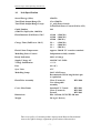
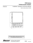
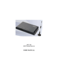
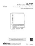
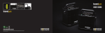
ESPRIT 1500 (BW-1072) OPERATING INSTRUCTIONS Bowens Esprit 1500 Operating Instructions. FIG 1 REAR PANEL 1. Sync Socket 2. Mains Inlet 3. Fuse (+ Spare Fuse) 4. Mains On/Off Switch 5. 6. 7. Modelling Lamp Control Switch Photocell On/Off Switch Sounder On/Off Switch FIG 2 SIDE VIEW 1. 2. 3. 4. 5. Latch Knob Flash Power Control ‘Ready’ Indicator Photocell Cover Test/Open Flash 6. Modelling Control 7. Flash Power Selector Switch 500 Ws, 1000 Ws or 1500 Ws 8. Digital Power Display 9. Cover Glass Dome -2- Bowens Esprit 1500 Operating Instructions. 1. General Welcome to the world-wide family of Bowens flash equipment users, and congratulations on selecting the latest compact flash in our range. The Esprit 1500 includes a unique combination of features not found in other monoblocs: x Power selection system, with easy-to-use selector switch and digital display allowing 1,2 or 3 capacitor banks to be combined to deliver maximum power outputs of 500, 1000 or 1500 Ws. x Auto power dump giving access to lower power selections without the need to manually dump a higher flash power first. The digital display provides an indication of the state of the power dump by blinking. x Audible flash ‘Ready’ confirmation. x 650 W halogen modelling lamp. x Built-in fan cooling system. x Uncoated flash tube with separate UV coated glass dome fitted as standard over the modelling lamp and flash tube for safety. Clear and frosted domes are also available as accessories for special applications. 2. Safety Notes x The Esprit 1500 must not be used in an environment where moisture or flammable vapour is likely to come in contact with the unit. x A cover glass dome should always be fitted during use. x A fire hazard exists if flammable materials are placed in close proximity to the flash tube, modelling lamp or glass dome when the unit is in use. x Switch off and disconnect supply before changing fuse, modelling bulb, flashtube, glass dome or reflector. x The charging and modelling circuitry is protected by a 10 A 20 mm fuse mounted on the rear panel (Fig.1). Always replace with a fuse of identical rating. x Do not restrict slots in case when in use. x Care must be exercised when handling equipment that has been in use. The reflector and front end of the unit can become Very Hot. x Due to the high voltage/high energy used in the Esprit 1500, servicing must be carried out by a qualified, authorised Service Centre. 3. Contents Of Carton 1. Esprit 1500 (Fitted with flashtube and modelling lamp) 2. Sync. Cord 3. Mains Lead 4. Instructions -3- Bowens Esprit 1500 Operating Instructions. 4. Power Supply Connections 190-250 V AC 50 Hz. Use mains lead supplied to connect to mains supply. 5. Operation The green illuminated On/Off Switch (Fig.1) on the rear panel controls the power to both the flash and the modelling lamp. Setting the switch to 1 turns the unit ‘ON’, with the switch illuminated, and 0 turns the unit ‘OFF’. When the unit has charged to the level set by the Flash Power Control (Fig.2) the green ‘Ready’ Indicator (Fig.2) will light. Your Esprit 1500 is now ready to fire. Note:- The Esprit 1500 synchronising circuit is inhibited until the unit is 100% charged. This ensures that every flash is identical. 6. Synchronisation Open Flash: For testing or multiple flash applications the Open Flash Pushbutton (Fig.2) can be used. The Esprit has a built in photocell enabling the unit to be triggered by the flash from any other flash unit or a small camera mounted flash gun. The photocell is mounted behind the red transparent cover on the top of the Esprit. Sync Socket: The standard quarter inch jack type socket on the rear panel of the unit (Fig.1) may be used for direct connection to a camera set to ‘x’ synchronisation. Two Esprit 1500 flash units may be connected together using a ‘y’ connector. An Infra Red Receiver or Omnicell may also be plugged into this socket. 7. Flash Power Selection / Indication The Flash Power Selector Switch (Fig 2) sets the maximum flash power available. The power selected, 500, 1000 or 1500 Ws, is shown on the Digital Power Display (Fig.2) and represents a coarse control range of 11/2 f-stops. The Flash Power Control (Fig.2) provides a continuous adjustment within the range selected, over a five f-stop range from full to one thirty second (1/32) power. Rotating the Flash Power Control (Fig.2) from full to half, half to quarter, quarter to eighth, eighth to sixteenth and sixteenth to thirty second gives a reduction in output equivalent to 1 f-stop for each step. The total control range using the Flash Power Control and Flash Power Selector Switch is 61/2 f-stops. The auto-dump feature enables lower flash powers to be selected without requiring the unit to be flashed first to dump the higher power. The digital display blinks during the power dump to provide an indication of the status. 8. Modelling Lamp Control With the Modelling Lamp Control Switch (Fig.1) in the central position the modelling light is ‘OFF’. With the switch set to ‘Intermittent’ the modelling light will go out when the unit is flashed and come back on when the unit comes to ready. This enables -4- Bowens Esprit 1500 Operating Instructions. the photographer to see from the camera position that all Esprit units in use have fired. With the switch set to ‘Continuous’ the modelling light remains ‘ON’ all the time. The modelling light may be varied in ratio with the flash power output by aligning the indicator line on the Modelling Lamp Control (Fig.2) with that of the Flash Power Control (Fig.2). 9. Audible ‘Ready’ Confirmation Set the Sounder Switch (Fig.1) to ‘ON’ to give a short beep when the unit comes to ready, to provide an audible ‘Ready’ confirmation. 10. Fuse The modelling and flash circuitry is protected by a single 10 amp (F) 20mm fuse mounted on the rear panel (Fig.1). Never replace the fuse with one of a different rating. As the fuse may blow when the modelling lamp fails always check the fuse when replacing the lamp. A spare fuse is supplied in the fuse holder. Always switch OFF the Esprit 1500 before changing the fuse or lamp. 11. Fitting / Removing A Reflector A range of reflectors is available for the Esprit 1500. To fit, slide the neck of the reflector over the front of the unit. Align the three pegs on the reflector with the three slots in the retaining ring, press down and turn clockwise to lock. To remove the reflector, press the Latch Knob (Fig.2), turn the reflector fully anti-clockwise and withdraw. If an umbrella is to be used a ‘Spill Kill’ (BW-1885) should be fitted and the umbrella inserted through the hole in the mounting bracket on the Spill Kill and locked into position with the knurled screw. 12. Replacing the Modelling Lamp Switch off the unit and disconnect from the supply. Remove the Glass Dome (Fig.2) by depressing the Dome Retaining Buttons (Fig.2) and lifting it away from the unit. Take care removing the old modelling lamp from the holder, particularly if the glass is broken. Plug the replacement modelling lamp into the holder. Do not touch the replacement lamp with fingers. Use clean impervious cloth, paper or the lamp packaging materials. Discard the old modelling lamp safely using the packaging from the new lamp. Hook the glass dome over one of the dome retaining buttons, depress the other button and refit the dome over the ridge in the top hat. Ensure that both buttons drop into the retaining holes in the dome (marked with a small white line). -5- Bowens Esprit 1500 Operating Instructions. 13. Replacing the Flashtube Warning High Voltage Do not touch the flashtube assembly for thirty minutes after disconnecting from supply. Switch off the unit, disconnect from the mains supply and then wait thirty minutes before touching / removing the flashtube. Remove the glass dome as described in section 12. Unwind the twisted Trigger wire from the trigger terminal tag, and gently pull the flashtube assembly out of the unit. Hold the replacement assembly as shown in Fig.3 and locate the three brass sockets onto the plugs in the front of the unit. Press down evenly until all the plugs and sockets are fully engaged. Pass the trigger wire through the hole in the trigger terminal tag and wind around the tag, ensuring that the wire does not touch the metal top hat. Refit the glass dome as described in section 12. Discard the old flash tube safely using the packaging from the new tube. FIG. 3 FLASH TUBE ASSEMBLY -6- Bowens Esprit 1500 Operating Instructions. 14. Unit Specification Stored Energy (Max) 1500 Ws Total Flash Output Range Ws 15 to 1500 Ws Total Flash Output Range f-stops 11/2 with Power Switch 5 with Flash Power Control (Full to 1/32) Guide Number (1500 Ws, 50q Keylite, 100 ISO) 160 Flash Duration (Full Power)T 0.5 1/1100 1/1500 1/2200 (1500 Ws) (1000 Ws) (500 Ws) Charge Time (Full Power 240 V) 2.9 s 1.9 s 1.1 s (1500 Ws) (1000 Ws) (500 Ws) Flash Colour Temperature Approx. 5600 K UV coated as standard Modelling Power Control Independent & fully variable Ready Indication 100% of charge Supply Voltage AC 190-250 VAC 50 Hz Voltage Stabilisation +/- 1% Fuse 10 A (F) Sync Volts 15 V Modelling Lamp 240 V 650 W max. Recommended P2/16 long life hair pin or equivalent Flash Tube Assembly Clear (Uncoated) User changeable assembly BW-2980 Cover Glass Dome Standard UV Coated Clear (Uncoated) Frosted BW-2981 BW-2982 BW-2983 Dimensions DIA. 145 mm, LENGTH 490 mm Weight 5.0 kg (11 lb 0 oz) Due to our policy of constant product improvement Bowens International reserve the right to change equipment specifications without notice. -7- Bowens Esprit 1500 Operating Instructions. Esprit 1500 Instructions: (BW-1072) BWL-0235/1 BOWENS INTERNATIONAL LIMITED 355 Old Road Clacton-on-Sea Essex CO15 3RH Tel: +44(0) 1255 422807 Fax: +44(0) 1255 436342 -8-