1
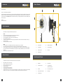
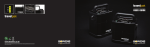
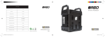
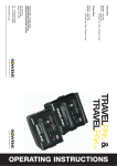
RINGFLASH PRO
USER GUIDE BWL-0485
BOWENS INTERNATIONAL LTD
355 Old Road
Clacton-On-Sea
Essex
CO15 3RH
Tel:
Fax:
+44 (0)1255 422807
+44 (0)1255 436342
www.bowens.co.uk
INTRODUCTION
M
OUNTING RINGFLASH PRO TO LIGHT
STAND
INTRODUCTION
P
RODUCT OVERVIEW
Dear Valued Customer,
B
D
Thank you for choosing the Bowens Ringflash Pro.
The Bowens Ringflash Pro has been developed by working closely with professional photographers to create a product suitable for, and which meets the
standards of even the most demanding of todays professional studios. For details of all related Bowens products please contact your local distributor, a
list of which can be found at www.bowens.co.uk. In order to obtain the full benefit from your purchase please take a few moments to familiarise yourself
with this user manual.
F
Thank you,
Bowens International Ltd.
SAFETY INFORMATION
C
G
Please take time to read through and follow these safety instructions:
ALWAYS
be careful of and avoid placing the Ringflash Pro cable where it can be tripped over.
switch the pack on AFTER the Ringflash Pro has been connected.
ensure that the Ringflash Pro cable connector is correctly fitted before using.
remove the protective cover before use.
turn OFF the pack, disconnect from the power supply, unplug the Ringflash Pro and allow to cool down before attaching or removing any
accessories or reflectors.
use with the protective glass cover attached.
•
•
•
•
•
•
NEVER
place heavy objects on top of the Ringflash Pro cables and avoid running them over sharp or hot objects.
use the equipment with damaged cables. Have them replaced as soon as possible. NEVER attempt to repair them yourself.
use in an environment where moisture, water vapour or inflammable liquids, vapour or materials may come into contact with the Ringflash
Pro or pack. The flash output as well as modelling lamps can cause ignition of or damage to materials that may come into contact with the
Ringflash Pro.
obstruct the airflow around the Ringflash Pro or pack.
•
•
•
•
GENERAL FEATURES
E
N.B. Ringflash Pro shown with optional reflector
A
A.)
Soft Grip Handle
B.)
Modelling On/Off Switch
C.)
Camera Bracket
D.)
Protective Glass Cover
E.)
Built-In Cooling Fan
F.)
Flash Tube
G.)
Modelling Lamps
ITEMS PROVIDED IN CARTON
The Ringflash Pro is designed for use with the all Bowens 20-Pin Quad socket generators
•
•
•
•
•
•
•
Flash tubes with colour corrective UV coating.
Adjustable modelling lamps with On/Off switch.
Easy fitting of reflectors and accessories.
Universal camera bracket.
Can be used with light stand or camera stand.
Incorporates handle for portable hand held use.
Includes built-in thermal cut out. The cut out will only stop the Ringflash Pro from flashing. If this occurs it is advised to turn off the modelling
and allow to cool for 10 minutes. Do not turn off the pack as the Ringflash Pro fans will aid and speed up the cooling process.
1
1.)
Ringflash Pro
2.)
Camera Bracket
3.)
Camera Mount Thread
4.)
12 x Modelling Lamps
(Includes 10 plus 2 spare)
5.)
Flash Tube
6.)
Clear Protective Glass Cover
7.)
Frosted Protective Glass Cover
8.)
Brass Spigot
9.)
2 x Blanking Plugs
2
MOUNTING RINGFLASH PRO TO LIGHT STAND
FLASHTUBE ASSEMBLY REPLACEMENT
WARNING HIGH VOLTAGE
STEP 1.)
Mount the Camera Bracket to the selected support system as shown in fig. 1.
STEP 2.)
Once the Ringflash Pro is mounted onto the selected support system, simply tighten the mount screw as shown in fig. 2 to hold in
position.
AFTER USE DO NOT TOUCH THE FLASHTUBE ASSEMBLY FOR THIRTY MINUTES DUE TO EXTREME HEAT
STEP 1.)
Ensure that the Ringflash Pro is switched off and disconnected from the mains supply and wait for thirty minutes to allow to cool
down before touching / removing the flashtube.
STEP 2.)
Before removing the flashtube assembly from the Ringflash Pro first remove the front protective glass cover (before removing
check the glass has cooled sufficiently to touch). Once the glass cover has been removed take out the two modelling lamps
next to the trigger wire tab and then unwind the trigger wire from the tab as shown in fig. 7. It is recommended to remove the two
modelling lamps next to the trigger wire tab to allow more room to when unwinding the trigger wire and so not to damage the
lamps.
STEP 3.)
To remove the flashtube assembly hold gently on both sides and pull away evenly from the Ringflash Pro as shown in fig. 8. To
replace the flashtube assembly, simply place all four support legs into the correct fittings and gently push back in ensuring all four
legs are placed back in evenly and secured by fully inserting into the flashtube leg connections.
N.B. Always replace with the correct flashtube assembly.
fig.1
fig.2
MOUNTING RINGFLASH PRO TO CAMERA STAND
STEP 1.)
To mount the Ringflash Pro to a camera stand, first place the brass spigot on top of the camera plate and fasten to the camera
mounting thread as shown in fig. 3.
STEP 2.)
Next place the Ringflash Pro camera bracket on top of the brass spigot and lock in place by tightening the thumb screw as shown
in fig.4.
STEP 3.)
Attach the Ringflash Pro to the camera bracket as shown in fig. 5 and secure in place using the thumb screws provided.
fig.7
fig.8
MODELLING LAMP REPLACEMENT
N.B. When attaching the Ringflash Pro to the camera bracket ensure that the Ringflash Pro handle is positioned to one side to
allow the Ringflash Pro complete freedom of movement without the handle coming into contact with the camera stand.
STEP 4.)
Once the Ringflash Pro is secured in place, next attach the camera to the camera bracket. Your setup should appear as shown in
fig.6.
fig.3
3
fig.4
fig.5
WARNING HIGH VOLTAGE
AFTER USE DO NOT TOUCH THE MODELLING LAMPS FOR THIRTY MINUTES DUE TO EXTREME HEAT
STEP 1.)
Ensure that the Ringflash Pro is switched off and disconnected from the mains supply and wait for thirty minutes to allow to cool
down before touching / removing the modelling lamps.
STEP 2.)
Before removing any modelling lamps from the Ringflash Pro first remove the front protective glass (before removing check the
glass has cooled sufficiently to touch). To remove the modelling lamps grip gently between fingers (always ensure that you do not
touch the modelling bulbs directly with your fingers, use a cloth or a tissue (as shown in fig.9.), this is because the residue from
your fingers can shorten the life span of the bulb) and pull away slowly from the Ringflash Pro. To replace the modelling lamps
simply align the two legs of the lamp with the correct fittings and gently push in ensuring that the lamp legs are fully inserted.
fig.6
fig.9
4
FITTING / REMOVING QUAD CONNECTORS TO PACK
OPERATION
•
Before use ensure that the pack is switched off.
•
Fit the Ringflash Pro connectors to the pack. To ensure latch retention first insert the tab on the front of the cable plug into the pack socket (as
shown in fig. 10) and then press down firmly on the cable entry end (as shown in fig. 11).
•
Switch the pack ‘on’ and ‘test’ flash the Ringflash Pro to ensure operational.
•
After use always make sure that the Ringflash Pro has adequate time to cool down.
•
To remove the plug make sure all power to the Ringflash Pro is switched ‘off’, press the spring latch away from the plug and lift from the
cable entry end (as shown in fig.12).
fig.10
fig.11
fig.12
ACCESSORIES
Accessories available to fit the Ringflash Pro:
•
BW-7674
Ringflash Pro Reflector (fig.13)
•
BW-7675
110º Reflector with Diffuser (fig. 14)
Part Number (230V)
BW-7670
Part Number (117V)
BW-7670US
Maximum Power
4800Ws
Flash Duration (Maximum)
1/1600 sec @ 3000Ws
Flash Duration (Minimum)
1/4500 sec @ 500Ws
Guide Number
@ 3000Ws with 50º Keylite Reflector
86
Flashtube Assembly
1 x Single Tube (BW-7673)
User Replaceable
Modelling Lamp (117V)
10 x 12V 20W G4 Halogen LAM-760 (BW-7671)
Modelling Lamp (230V)
10 x 24V 20W G4 Halogen LAM-765 (BW-7672)
Cable Length
5m
Dimensions
204mm ø x 80mm (87.5mm with Baffle)
Aperture
100mm ø
Weight (inc. Cable)
2.7Kg
Weight (inc. Camera Bracket & Cable)
3.43Kg
SPARE PARTS AVAILABLE
fig.13
5
fig.14
BW-7671 12V 20W G4 Halogen (for use on 117V)
BW-7672 24V 20W G4 Halogen (for use on 230V)
BW-7676 Glass Lens (Clear)
BW-7677 Glass Lens (Frosted)
BW-7673 Flashtube Assembly
6