1
Phantom Help File
© 2010 Vision Research - An AMETEK Company
Software Revision: 685
Updated: Thursday, March 18, 2010
Contents
3
Table of Contents
Foreword
Part I Welcome to Phantom Help
9
12
1 Getting Help................................................................................................................................... 13
2 Other Useful...................................................................................................................................
Phantom Resources
14
3 EULA (End User
...................................................................................................................................
License Agreements)
15
4 Important Warnings
...................................................................................................................................
and Cautions
34
5 Important Operational
...................................................................................................................................
Notes and Safety Instructions
38
Part II Getting Started
44
1 Phantom Camera
...................................................................................................................................
Control Unit Requirements
45
2 Preparing Your
...................................................................................................................................
Computer
47
3 Installing the...................................................................................................................................
Phantom Camera Control Software
48
4 Installing the...................................................................................................................................
Phantom STG (Serial Tag Number) File
48
5 Define the Phantom
...................................................................................................................................
Control Unit IP Address
49
6 IEEE 1394 Hardware
...................................................................................................................................
and Driver Installation
51
7 Verify Camera
...................................................................................................................................
Connection
53
Part III Quick Start Guides
56
1 Phantom Cameras via Phantom Camera Control (PCC)
Application ................................................................................................................................... 57
2 Phantom Miro
...................................................................................................................................
Touch-Sensitive LCD Cameras
62
3 Phantom 65 ...................................................................................................................................
or HD-Series Cameras via On-Camera Controls
67
Part IV Phantom Camera Control Application - Help
70
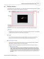
1 The User Interface
................................................................................................................................... 71
Menubar
.......................................................................................................................................................... 73
Toolbar
.......................................................................................................................................................... 79
Preview/Playback
..........................................................................................................................................................
Panel
82
Status Bar .......................................................................................................................................................... 83
The Control Panels
.......................................................................................................................................................... 84
Manager .........................................................................................................................................................
Control Panel Components
85
Live Control
.........................................................................................................................................................
Panel Components
87
Play Control
.........................................................................................................................................................
Panel Components
102
2 Step-by-Step
...................................................................................................................................
Procedures
109
Menubar Procedures
.......................................................................................................................................................... 109
Cine Menu
.........................................................................................................................................................
Procedures
109
Opening a Saved
.........................................................................................................................................
Cine File
109
Saving a Cine File
......................................................................................................................................... 110
Saving All RAM.........................................................................................................................................
to File, (MultiCine)
114
Saving All Flash
.........................................................................................................................................
to File, (Flash/CineMag)
118
Saving a Cine to
.........................................................................................................................................
Flash Memory
122
© 2010 Vision Research - An AMETEK Company
3
4
Phantom Help File
Select&Save Cines
.........................................................................................................................................
to File
Camera .........................................................................................................................................................
Menu Procedures
Adding a Simulated
.........................................................................................................................................
Camera
Copy Parameters
.........................................................................................................................................
To..
Loading Camera
.........................................................................................................................................
Settings..
Saving Camera.........................................................................................................................................
Settings..
Deleting All RAM
.........................................................................................................................................
Cines
Erasing Flash Memory
.........................................................................................................................................
View Camera Properties
.........................................................................................................................................
Assign a Secondary
.........................................................................................................................................
IP Address
Tools Menu
.........................................................................................................................................................
Procedures
Tools - Image Processing
.........................................................................................................................................
Adjustment Procedures
Firmware Control
.........................................................................................................................................
(Nucleus) - Upgrading Camera Firmware Procedure
Enable/Disable.........................................................................................................................................
Logging
Preferences - Phantom
.........................................................................................................................................
Camera Control Preferences
Window .........................................................................................................................................................
Menu Procedures
Tile Preview/Playback
.........................................................................................................................................
Panels
Auto Tile Preview/Playback
.........................................................................................................................................
Panels
Selecting an Open
.........................................................................................................................................
Preview/Playback Panel
Help Menu
.........................................................................................................................................................
Procedures
Toolbar Procedures
..........................................................................................................................................................
Open a Saved
.........................................................................................................................................................
Cine File
Save to .........................................................................................................................................................
File
Save All.........................................................................................................................................................
Cines From This Camera..
Image Tools
.........................................................................................................................................................
Video Out
.........................................................................................................................................................
Snapshot
.........................................................................................................................................................
Preview/Playback
..........................................................................................................................................................
Panel Procedures
Performing
.........................................................................................................................................................
a White Balance Adjustment
Manager Control
..........................................................................................................................................................
Panel Procedures
Individual
.........................................................................................................................................................
Camera Control
Simultaneous
.........................................................................................................................................................
Multiple (Group) Camera Control
Delete a.........................................................................................................................................................
Sub-Group, Camera, or Cine File
Opening.........................................................................................................................................................
a Cine File from Camera Memory or CineMag
Opening.........................................................................................................................................................
a Cine File Under the Files Group Tree
Live Control..........................................................................................................................................................
Panel Procedures
Camera .........................................................................................................................................................
Settings
Synchronize or.........................................................................................................................................
Set the Internal Clock of a Phantom Camera
Specify the Time
.........................................................................................................................................
Zone Reference
Perform a CSR,
.........................................................................................................................................
(Current Session Reference), Calibration Adjustment
Perform a Black
.........................................................................................................................................
Reference Calibration Adjustment
Define the Image
.........................................................................................................................................
Pixel Bit Depth
Specify the Cine
.........................................................................................................................................
Memory Partitions
Define the Automatic
.........................................................................................................................................
Lens Control
Cine Settings
.........................................................................................................................................................
Define the Resolution
.........................................................................................................................................
Define the Sample
.........................................................................................................................................
Rate
Define the Exposure
.........................................................................................................................................
Time
Define an EDR,.........................................................................................................................................
(Extreme Dynamic Range), Exposure Time
Low Light
.........................................................................................................................................
Define a Post Trigger
.........................................................................................................................................
Value
Advanced
.........................................................................................................................................................
Settings
Define the Cine.........................................................................................................................................
Advanced Options
Define the CineMag
.........................................................................................................................................
Option
123
134
134
136
138
139
140
140
141
142
144
144
145
148
149
152
152
152
153
153
154
154
154
158
162
162
163
164
164
165
165
165
166
166
168
169
169
169
170
171
173
174
175
176
177
177
178
178
180
181
182
184
184
185
© 2010 Vision Research - An AMETEK Company
Contents
5
Define the Start/End
.........................................................................................................................................
of Recording Actions Parameters
Define the External
.........................................................................................................................................
Sync Parameters
Enable Real Time
.........................................................................................................................................
Output Parameters
Define the Acquisition
.........................................................................................................................................
Signals
Define the Trigger
.........................................................................................................................................
Settings
Define the Pretrigger
.........................................................................................................................................
Pin Is:
Define the Ready
.........................................................................................................................................
Signal Ends At:
Define the Miro/Strobe
.........................................................................................................................................
Pin Is:
Define the Starts
.........................................................................................................................................
In Option
Define the
.........................................................................................................................................................
Auto Exposure
Define the
.........................................................................................................................................................
Frame Rate Profile
Define the
.........................................................................................................................................................
Image Content Trigger (Image-Based Auto-Trigger)
Define the
.........................................................................................................................................................
Continuous Recording Parameters
Capture .........................................................................................................................................................
or Record Image Data
Trigger or
.........................................................................................................................................................
Abort Recording
Play Control..........................................................................................................................................................
Panel Procedures
Cine Selection
.........................................................................................................................................................
Select the
.........................................................................................................................................................
Playback Mode
Reviewing
.........................................................................................................................................................
Cine File
Perform .........................................................................................................................................................
a Quick Search Through a Cine File
Edit a Cine
.........................................................................................................................................................
File
Save a Cine
.........................................................................................................................................................
File
View Frame
.........................................................................................................................................................
Info
View Cine
.........................................................................................................................................................
Info
View SAM-3
.........................................................................................................................................................
Signaling
Specify the
.........................................................................................................................................................
Time Translation
Part V Phantom CineMag - Help
186
187
193
193
196
196
197
197
198
199
201
203
205
209
210
211
211
212
213
215
217
220
221
221
222
225
228
1 Defining the
...................................................................................................................................
Operational Mode
229
2 Recording ...................................................................................................................................
to a Phantom CineMag
231
3 Viewing a Cine
...................................................................................................................................
File Stored in Phantom CineMag
236
4 Editing a Cine
...................................................................................................................................
File Stored in Phantom CineMag
238
5 Erasing Files
...................................................................................................................................
from the Phantom CineMag
240
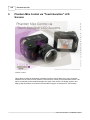
Part VI Phantom Miro Control via "Touch-Sensitive"
LCD Screens
242
1 The LCD Display
...................................................................................................................................
Screens
243
LIVE PRE Display
..........................................................................................................................................................
Power Off Display
..........................................................................................................................................................
LIVE WTR Display
..........................................................................................................................................................
LIVE TRG Display
..........................................................................................................................................................
LIVE CST Display
..........................................................................................................................................................
PLAY CST Display
..........................................................................................................................................................
Edit/Save Display
..........................................................................................................................................................
Save Display..........................................................................................................................................................
Delete Existing
..........................................................................................................................................................
Recording Display
MultiCine Allocation
..........................................................................................................................................................
Display
Reallocate Memory
..........................................................................................................................................................
and Delete All Cines Display
Cine Screen ..........................................................................................................................................................
Display
Image-Based..........................................................................................................................................................
Auto-Trigger Display
244
247
250
252
254
256
259
262
264
265
267
268
271
2 Step-by-Step
...................................................................................................................................
Procedures
274
© 2010 Vision Research - An AMETEK Company
5
6
Phantom Help File
Turning On the
..........................................................................................................................................................
Phantom Miro Camera
Changing Settings
..........................................................................................................................................................
via the LCD Display
Specifying
.........................................................................................................................................................
the Trigger (Post Trigger Value) Point
Specifying
.........................................................................................................................................................
the Sample Rate
Specifying
.........................................................................................................................................................
the Resolution
Specifying
.........................................................................................................................................................
the Exposure
Accessing the
..........................................................................................................................................................
Power Off Display
Performing a..........................................................................................................................................................
White Balance Adjustment
Performing a..........................................................................................................................................................
Black Reference Adjustment
Selecting an..........................................................................................................................................................
Exposure Index
Formatting the
..........................................................................................................................................................
CompactFlash Card
Placing a Phantom
..........................................................................................................................................................
Miro Camera Into the LIVE WTR (Recording) Mode
Triggering the
..........................................................................................................................................................
Miro Camera
Viewing a Stored
..........................................................................................................................................................
Cine File
Viewing a MultiCine
..........................................................................................................................................................
File Stored in the Type 1 Compact Flash Card
Deleting a Stored
..........................................................................................................................................................
Cine File
Editing a Stored
..........................................................................................................................................................
Cine File
Saving a Cine
..........................................................................................................................................................
File
Power Off the
..........................................................................................................................................................
Camera
Using MultiCine
..........................................................................................................................................................
with a Phantom Miro Camera
Using Image-Based
..........................................................................................................................................................
Auto-Trigger with a Phantom Miro
Part VII Phantom 65 or Phantom HD Control via
"On-Camera" Control Buttons
275
275
276
276
277
277
278
278
279
279
280
281
281
282
283
284
284
285
287
287
289
298
1 Defining the
...................................................................................................................................
Video Out Parameters
300
2 The Monitor/ViewFinder
...................................................................................................................................
Display Screens
301
LIVE PRE/LIVE
..........................................................................................................................................................
Display Screens
SETUP Display
..........................................................................................................................................................
Screens
LIVE WTR/LIVE
..........................................................................................................................................................
REC Display Screens
LIVE TRG Display
..........................................................................................................................................................
Screen
LIVE CST Display
..........................................................................................................................................................
Screen
SELECT Display
..........................................................................................................................................................
Screen
PLAY CST Display
..........................................................................................................................................................
Screen
302
306
312
316
320
323
326
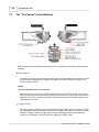
3 The "On-Camera"
...................................................................................................................................
Control Buttons
330
4 Using the "On-Camera"
...................................................................................................................................
Control Buttons
332
Defining the..........................................................................................................................................................
Operational Mode
Switching Between
..........................................................................................................................................................
the Preview, Zoom, and Threshold Features
Changing the
..........................................................................................................................................................
Camera's Operational States
Define the Setup
..........................................................................................................................................................
and Recording Parameters
Providing a "Soft-Trigger"
..........................................................................................................................................................
Play/Pause a..........................................................................................................................................................
Stored Cine File
Edit a Stored..........................................................................................................................................................
Cine File
Placing the Camera
..........................................................................................................................................................
Back Into the Capture Mode
Part VIII Phantom Cine Control Panel - Help
333
334
335
335
338
339
340
341
344
1 Using the Phantom
...................................................................................................................................
Cine Control Panel
344
Part IX Functional Descriptions
348
1 Black Reference/Current
...................................................................................................................................
Session Reference Adjustments
348
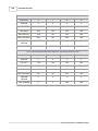
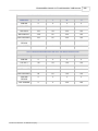
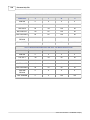
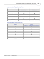
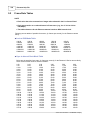
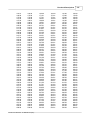
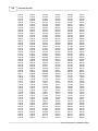
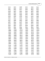
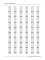
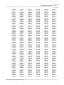
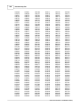
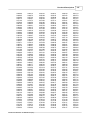
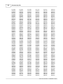
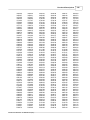
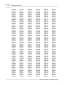
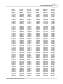
2 Frame Rate...................................................................................................................................
Tables
350
© 2010 Vision Research - An AMETEK Company
Contents
7
3 Image-Based
...................................................................................................................................
Auto-Trigger
364
4 Image Processing
...................................................................................................................................
Effects and Filters
366
5 Phantom CineMag
...................................................................................................................................
Operational Modes
374
6 Phantom File
...................................................................................................................................
Naming Convention
374
Phantom File..........................................................................................................................................................
Naming Convention Examples
377
7 Phantom STG,
...................................................................................................................................
(Serial Tag Number), File
380
8 Supported ...................................................................................................................................
File Formats
381
9 Supported ...................................................................................................................................
Video System Formats
389
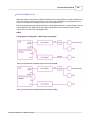
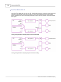
10 Versatile Dual
...................................................................................................................................
HD-SDI
392
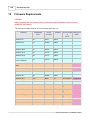
Part X Firmware Requirements
Index
400
405
© 2010 Vision Research - An AMETEK Company
7
Foreword
9
Phantom Help File
Last Updated: 3/18/2010
by Vision Research
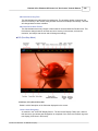
Thank you for using Phantom! You chose the most powerful and easiest
camera to discover the potential of your ideas. Phantom is a totally digital high
speed imaging system capable of recording of high resolution images. If an
ordinary photograph captures a moment in time, each high resolution
Phantom image explores a remarkably unpredictable moment in time.
The Phantom Camera Control Software, and the On-Camera Control
Buttons provides you with complete creative control over time. You can select
any frame rate in increments of one frame per second. Shift the frame rate a
little and move a scene to a slightly future viewpoint. Or shift the frame rate a
lot and move a scene to some long passing moment in time. You will enjoy the
ability of having seamless control of the duration, speed and time of every
element of the shot.
With its two main components of the system the Phantom imager with
advanced CMOS technology, and the Phantom Camera Control software, they
form a system that provides high speed. high resolution image capture in
digital cine format, with communications across multiple digital and analog
protocols.
This operational guide has been meticulously designed to ease
the anxieties associated with learning how to use your Phantom camera and
its powerful features.
Enjoy the Phantom Experience!
© 2010 Vision Research - An AMETEK Company
Part
I
12
1
Phantom Help File
Welcome to Phantom Help
Thank you for using Phantom! You chose the most powerful and
easiest camera to discover the potential of your ideas. Phantom is a
totally digital high speed imaging system capable of recording
thousands of high resolution images per second. If an ordinary
photograph captures a moment in time, each high resolution
Phantom image explores a remarkably unpredictable moment in
time.
The new version of the Phantom Camera Control Software
application offers everything that the earlier versions included and
much more. Virtually, every aspect of the program has been
overhauled and improved, without sacrificing intuitive ease of use.
This Help file will reduce the learning curve, and ease the anxieties
associated with learning how to use your Phantom camera and its
powerful features quickly.
Enjoy the Phantom Experience!
© 2010 Vision Research - An AMETEK Company
Welcome to Phantom Help
1.1
13
Getting Help
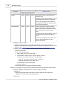
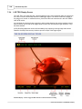
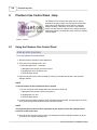
As you would expect the Phantom Help File provides you with plenty of help on every aspect of using
the Phantom Camera Control software application. In addition to this very comprehensive help file,
which are actually a complete user manual, the Help File also has extensive context-sensitive help
that you can access.
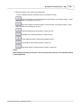
Using the help file
This help is designed to be used on-screen. It is extensively cross-linked so that you can find more
relevant information to any subject from any location. If you prefer reading printed manuals a PDF
version of the entire help has also been provided to you. This may be useful as a reference, but you
will probably find that the active hyperlinks, cross-references and active index make the on-screen
electronic version of the help much more useful.
Getting a printed help manual
Please don't try to print the HTML Help version of the help from the Microsoft help viewer, it would
look terrible. You can find a formatted PDF version of the entire documentation designed for printing
in the same directory the Phantom Camera Control application was installed.
As mentioned above, however, you will probably find that the on-screen version of the help is much
more useful because of the hyperlinks and cross-references.
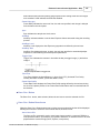
Quick Start Guides
See Quick Start Guides in the help for some basic tutorials to get you started using your Phantom
camera.
© 2010 Vision Research - An AMETEK Company
14
1.2
Phantom Help File
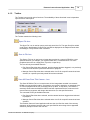
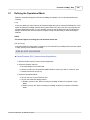
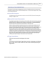
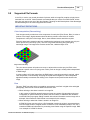
Other Useful Phantom Resources
If you have any questions not answered by this help system,
please don't hesitate to contact our support center!
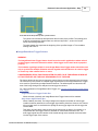
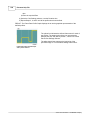
Are you a member of the PhantomZone user forum? No, click the
PhantomZone logo or the following link to sign up now: http:\
\www.visionresearch.com/phantomzone.
This is a great source for additional information on Phantom
cameras in general, alerts and FAQ's, product news, software
and hardware suggestions, and various discussion groups in
particular.
Already a member, check out "What's New", just click the
PhantomZone logo to sign in.
This web site, http://focus.visionresearch.com, offers news about
Vision Research products and provides application notes,
technical tips, FAQ’s and general news of interest on the subject
of high speed digital photography.
Vision Research proudly offers a hands-on, instructor-led course
designed to expand your knowledge of Phantom Miro and vSeries camera operations using proven methodologies with Vision
Research’s award-winning Phantom Digital Imaging Systems.
This course covers a full range of training from the basics of the
Phantom system and its graphical user interface (GUI) to many
advanced analysis features.
After completing this course, you will have the knowledge and
practical understanding necessary to successfully utilize and
deploy the Phantom Digital Imaging System to meet your imaging
requirements. For more information please visit, http://www.
visionresearch.com/index.cfm?sector=htm/files&page=Training
© 2010 Vision Research - An AMETEK Company
Welcome to Phantom Help
1.3
15
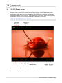
EULA (End User License Agreements)
Phantom Camera Control Software End User License Agreement (EULA)
This run-time copy of Phantom ("the Software Product") and accompanying documentation are licensed and
not sold. The Software Product is protected by copyright laws and treaties, as well as laws and treaties
related to other forms of intellectual property. Vision Research, Inc. or its subsidiaries, affiliates, and
suppliers (collectively "VRI") own intellectual property rights in the Software Product. The licensee's
("you" or "your") ability to download, use, or copy the Software Product is subject to and governed by the
terms and conditions of this End User License Agreement ("Agreement").
1. Acceptance
YOU ACCEPT AND AGREE TO BE BOUND BY THE TERMS AND CONDITIONS OF THIS
AGREEMENT BY SELECTING THE "ACCEPT" OPTION AND DOWNLOADING THE
SOFTWARE PRODUCT OR BY INSTALLING, USING, OR COPYING THE SOFTWARE
PRODUCT. YOU MUST AGREE TO ALL OF THE TERMS AND CONDITIONS OF THIS
AGREEMENT BEFORE YOU WILL BE ALLOWED TO DOWNLOAD THE SOFTWARE
PRODUCT. IF YOU DO NOT AGREE TO ALL OF THE TERMS OF THIS AGREEMENT, YOU
MUST SELECT "DECLINE" AND YOU MUST NOT INSTALL, USE, OR COPY THE SOFTWARE
PRODUCT.
2. License Grant
Subject to the terms and conditions hereof, VRI grants you a non-exclusive and non-transferable right to (a)
install and execute on a single central processing unit within a computer one copy of the Software Product
and (b) make one additional copy of the Software Product for backup and archival purposes only. The
archival copy must be on a storage medium other than a hard drive, and may only be used for the
reinstallation of the Software Product. This Agreement does not permit the installation or use of multiple
copies of the Software Product, or the installation of the Software Product on more than one computer at
any given time, on a system that allows shared used of applications, on a multi-user network, or on any
configuration or system of computers that allows multiple users. Multiple copy use or installation is only
allowed if you obtain an appropriate licensing agreement for each user and each copy of the Software
Product. Except as expressly set forth herein or in a separate written agreement, you shall be solely
responsible for the entire installation, supervision, training, management, support, maintenance and
control of the Software Product, including all responsibility for installation and for maintenance of
hardware and proper machine configuration. The Software Product, including any and all updates and
upgrades, shall be deemed accepted by you immediately upon download, copying, or receipt from VRI.
The rights granted to you under this Agreement are rights that may be exercised solely by you.
3. Restrictions
3.1 Restrictions on Transfer
Without first obtaining the express written consent of VRI, you shall not assign your rights or obligations
under this Agreement, or redistribute, encumber, sell, rent, lease, sublicense, or otherwise transfer your
rights to the Software Product. Subject to the foregoing, this Agreement will be binding upon and inure to
the benefit of the parties, their respective successors and permitted assigns.
3.2 Restrictions on Use
You may use the Software Product only as expressly provided in Section 2. Without limiting the foregoing,
you shall not: use, copy, or install the Software Product on any system with more than one computer, or
permit the use, copying, or installation of the Software Product by more than one user or on more than one
computer. If you hold multiple, validly licensed copies, you may not use, copy, or install the Software
Product on any system with more than the number of computers permitted by license, or permit the use,
copying, or installation by more users, or on more computers than the number permitted by license.
© 2010 Vision Research - An AMETEK Company
16
Phantom Help File
You shall not decompile, "reverse-engineer", disassemble, or otherwise attempt to derive the source code for
the Software Product.
You shall not use the database portion of the Software Product in connection with any software other than the
Software Product
3.3 Restrictions on Alteration
You shall not modify the Software Product, or any portion thereof, or create any derivative work of the
Software Product or its accompanying documentation. Derivative works include but are not limited to
translations. You may not alter any files or libraries in any portion of the Software Product. You may not
reproduce the database portion or create any tables or reports relating to the database portion. You shall
not change any proprietary rights notices which appear in the Software Product.
3.4 Restrictions on Copying
You shall not copy any part of the Software Product (digitally, electronically, in writing or otherwise), except
to the extent that licensed use inherently demands the creation of a temporary copy stored in computer
memory and not permanently affixed on a storage medium. You may make one archival copy which must
be stored on a medium other than a computer hard drive.
4. Proprietary Rights
You agree that the copyright(s), patent(s), trademark(s), trade secret(s) and all other intellectual proprietary
rights of whatever nature in the Software Product and related documentation, including derivative works,
are and shall remain the exclusive property of VRI and any third party suppliers. Nothing in this
Agreement should be construed as transferring any aspects of such rights to you or any third party. VRI
reserves any and all rights not expressly granted herein. PHANTOM is a trademark of Vision Research,
Inc., and shall not be used by you without VRI’s express written authorization.
5. Limited Software Product Warranty
For a period of sixty (60) days from the date of shipment, VRI warrants that when properly installed and used
under normal conditions, the Software Product will perform in accordance with VRI’s specifications.
6. Limited Storage Medium Warranty
For a period of ninety (90) days from the date of shipment, VRI warrants that when properly installed and
used under normal conditions, the storage medium on which the Software Product is shipped will be free
of material defects in material and workmanship.
7. Disclaimer of Warranties and Limitation of Liability
UNLESS OTHERWISE EXPLICITLY AGREED TO IN WRITING BY VRI, NO ADDITIONAL
WARRANTIES WHATSOEVER ARE MADE BY VRI. AFTER EXPIRATION OF THE APPLICABLE WARRA
SOFTWARE PRODUCT IS LICENSED "AS IS," WITHOUT ANY WARRANTIES
WHATSOEVER. VRI EXPRESSLY DISCLAIMS, AND YOU EXPRESSLY WAIVE, ALL
WARRANTIES, WHETHER EXPRESS OR IMPLIED, INCLUDING, BUT NOT LIMITED TO,
WARRANTIES OF MERCHANTABILITY, FITNESS FOR A PARTICULAR PURPOSE,
NON-INFRINGEMENT, SYSTEM INTEGRATION, NON-INTERFERENCE AND ACCURACY
OF INFORMATIONAL CONTENT. VRI DOES NOT WARRANT THAT THE SOFTWARE
PRODUCT WILL MEET YOUR REQUIREMENTS OR THAT THE OPERATION OF THE
SOFTWARE PRODUCT WILL BE SECURE, UNINTERRUPTED OR ERROR-FREE, OR
THAT ERRORS WILL BE CORRECTED. THE ENTIRE RISK OF THE SOFTWARE
PRODUCT’S QUALITY AND PERFORMANCE IS WITH YOU.
UNDER NO CIRCUMSTANCES SHALL VRI, ITS DIRECTORS, OFFICERS, EMPLOYEES OR
AGENTS BE LIABLE TO YOU OR ANY OTHER PARTY FOR INDIRECT,
CONSEQUENTIAL, SPECIAL, INCIDENTAL, PUNITIVE, OR EXEMPLARY DAMAGES OF
ANY KIND (INCLUDING LOST REVENUES OR PROFITS OR LOSS OF BUSINESS) ARISING
© 2010 Vision Research - An AMETEK Company
Welcome to Phantom Help
17
FROM THIS AGREEMENT, WHETHER RESULTING FROM IMPAIRED OR LOST DATA,
SOFTWARE OR COMPUTER FAILURE, OR FROM THE FURNISHING, PERFORMANCE,
INSTALLATION, OR USE OF THE SOFTWARE PRODUCT, WHETHER DUE TO A BREACH
OF CONTRACT, BREACH OF WARRANTY, OR THE NEGLIGENCE OF VRI OR ANY
OTHER PARTY, EVEN IF VRI IS ADVISED OF THE POSSIBILITY OF SUCH DAMAGES.
TO THE EXTENT THAT THE APPLICABLE JURISDICTION LIMITS VRI'S ABILITY TO
DISCLAIM ANY WARRANTIES, THIS DISCLAIMER SHALL BE EFFECTIVE TO THE
MAXIMUM EXTENT PERMITTED BY LAW.
8. Limitation of Remedies and Damages
Your sole remedy for a breach of this Agreement or of any warranty hereunder is the correction or
replacement of the Software Product, at VRI’s option. VRI reserves the right to substitute a functionally
equivalent copy of the Software Product as a replacement. If VRI is unable to provide a replacement or
substitute the Software Product or corrections to the Software Product, your sole alternate remedy shall be
a refund of payment rendered by you to VRI for the Software Product, exclusive of any costs for shipping
and handling
Any claim must be made within the applicable warranty period. All warranties cover only defects arising
under normal use and do not include malfunctions or failure resulting from misuse, abuse, neglect,
alteration, problems with electrical power, acts of nature, unusual temperatures or humidity, improper
installation, or damage determined by VRI to have been caused by you. All warranties on the Software
Product are granted only to you and are non-transferable. You agree to indemnify and hold VRI harmless
from any and all claims, judgments, liabilities, expenses, and/or costs (including reasonable attorneys'
fees) arising from your breach of this Agreement and/or acts or omissions.
9. Export Law Assurances
You acknowledge and agree that the Software Product and accompanying camera(s) (collectively, the
“Products”) may be subject to U.S. Export Administration Regulations. Diversion of the Products
contrary to U.S. law is prohibited. You agree that the Products are not being or will not be acquired for,
shipped, transferred, or re-exported, directly or indirectly, to proscribed or embargoed countries or their
nationals, nor will they be used for nuclear activities, chemical or biological weapons, or missile projects
unless authorized by the U.S. government. Proscribed countries are set forth in U.S. Export
Administration Regulations. You certify that you are not on the U.S. Department of Commerce's Denied
Persons List and are not a citizen, national, or resident of, or under the control of the government of Cuba,
Iran, Iraq, Libya, North Korea, Syria or any other country to which the U.S. has prohibited export. You
are responsible for complying with any applicable local laws, including but not limited to the export and
import regulations of other countries.
10. U.S. Government Restricted Rights
If the Software Product is being acquired by or on behalf of the U.S. Government or by a U.S. Government
prime contractor or subcontractor (at any tier), in accordance with 48 C.F.R. 227.7202-4 (for Department
of Defense ("DOD") acquisitions) and 48 C.F.R. 2.101 and 12.212 (for non-DOD acquisitions), the
government's rights in the Software Product and any documentation, including its rights to use, modify,
reproduce, release, perform, display or disclose the Software Product or any documentation, will be
subject in all respects to the license rights and restrictions provided in this Agreement.
11. Termination
VRI may terminate this Agreement immediately if you breach any of its provisions. Upon expiration,
cancellation or other termination of this Agreement, you shall immediately destroy all copies of the
Software Product. Sections 3 through 10 shall survive the expiration or termination of this Agreement.
12. Governing Law and Jurisdiction
This Agreement is governed by the laws of the State of New Jersey, without regard to its conflicts of law
provisions. In no event shall the United Nations Convention on Contracts for the International Sale of
© 2010 Vision Research - An AMETEK Company
18
Phantom Help File
Goods or any adopted version of the Uniform Computer Information Transactions Act apply to, or
govern, this Agreement. The parties consent to the exclusive jurisdiction of the courts of New Jersey.
13. Severability
If any provision of this Agreement shall be held to be invalid or unenforceable, the remainder of this
Agreement shall remain in full force and effect. To the extent any express or implied restrictions are not
permitted by applicable laws, these express or implied restrictions shall remain in force and effect to the
maximum extent permitted by such applicable laws.
14. Miscellaneous
VRI’s failure to exercise any right or remedy shall not be deemed a waiver of such right or remedy. Unless
otherwise agreed to in writing, any notice under this Agreement shall be delivered and addressed to you at
the address to which the Software Product is shipped, and to VRI at 100 Dey Road, Wayne, New Jersey
07470. Notice shall be deemed received by any party: (a) on the day given, if personally delivered or if
sent by confirmed facsimile transmission, receipt verified; (b) on the third day after deposit, if mailed by
certified, first class, postage prepaid, return receipt requested mail, or by reputable, expedited overnight
courier; or (c) on the fifth day after deposit, if sent by reputable, expedited international courier. Either
party may change its address for notice purposes upon notice in accordance with this Section. This
Agreement comprises the entire agreement between the parties relating to the subject matter hereof and
may be amended or modified only in a writing executed by both parties. In addition, if you are located
in Quebec, Canada, the following clause applies: The parties hereby confirm that they have
requested this Agreement be drafted in English. Les parties contractantes confirment qu’elles ont
exigé quele présent contrat et tous les documents associés soient redigés en anglais.
1667200.2
© 2010 Vision Research - An AMETEK Company
Welcome to Phantom Help
19
Vision Research Firmware End User License Agreement (EULA)
The software embedded in the accompanying camera and independently developed by or on behalf of Vision
Research, Inc. (the "Firmware"), and accompanying documentation, are licensed and not sold. The
Firmware is protected by copyright laws and treaties, as well as laws and treaties related to other forms of
intellectual property. Vision Research, Inc. or its subsidiaries, affiliates, and suppliers (collectively
"VRI") own intellectual property rights in the Firmware. The licensee's ("you" or "your") ability to
download, use, or copy the Firmware is subject to and governed by the terms and conditions of this End
User License Agreement ("Agreement").
1. Acceptance
YOU ACCEPT AND AGREE TO BE BOUND BY THE TERMS AND CONDITIONS OF THIS
AGREEMENT BY PURCHASING, RECEIVING, OR USING THE ACCOMPANYING CAMERA
(THE “CAMERA”).
2. License Grant
Subject to the terms and conditions hereof, VRI grants you a non-exclusive and non-transferable right to use
the Firmware only as it exists in the Camera at the time of shipping and for the sole purpose of operating
the Camera in accordance with manufacturer specifications. The Firmware, including any and all updates
and upgrades, shall be deemed accepted by you immediately upon receipt.
3. Restrictions
You may use the Firmware only as expressly provided in Section 2. Without limiting the foregoing, you shall
not: (a) copy the Firmware onto any multi-user, public or distributed network, or on any configuration or
system of computers that allows multiple users; (b) copy any part of the Firmware (digitally,
electronically, in writing or otherwise), except to the extent that licensed use inherently demands the
creation of a temporary copy stored in computer memory and not permanently affixed on a storage
medium; (c) change any proprietary rights notices which appear in the Firmware; (d) decompile,
"reverse-engineer", disassemble, or otherwise attempt to derive the source code for the Firmware; or (e)
modify the Firmware, or any portion thereof, or create any derivative work (including but not limited to
translations) of the Firmware or its accompanying documentation. The rights granted to you under this
Agreement are rights that may be exercised solely by you. Without first obtaining the express written
consent of VRI, you may not assign your rights or obligations under this Agreement, or redistribute,
encumber, sell, rent, lease, sublicense, or otherwise transfer your rights to the Firmware. Subject to the
foregoing, this Agreement will be binding upon and inure to the benefit of the parties, their respective
successors and permitted assigns.
4. Proprietary Rights
You agree that the copyright(s), patent(s), trademark(s), trade secret(s) and all other intellectual proprietary
rights of whatever nature in the Firmware and related documentation, including derivative works, are and
shall remain the exclusive property of VRI and any third party suppliers. Nothing in this Agreement
should be construed as transferring any aspects of such rights to you or any third party. VRI reserves any
and all rights not expressly granted herein. PHANTOM is a trademark of Vision Research, Inc., and shall
not be used by you without VRI’s express written authorization. Although the Firmware is proprietary to
VRI, certain other software contained in the Camera is subject to open source licenses, copies of which
are attached. These open source licenses shall continue to apply to any and all uses and distributions of
the applicable software undertaken by you, even if outside the scope of this Agreement. This Agreement
shall not be deemed to replace or otherwise amend any of your rights or obligations pursuant to any open
source license.
5. Warranties and Limitation of Liability
For a period of sixty (60) days from the date of shipment, VRI warrants that when properly installed and used
© 2010 Vision Research - An AMETEK Company
20
Phantom Help File
under normal conditions, the Firmware will perform substantially in accordance with VRI’s
specifications. NO ADDITIONAL WARRANTIES WHATSOEVER ARE MADE BY VRI. Warranty
claims must be made within the applicable warranty period. Warranties cover only defects arising under
normal use and do not include malfunctions or failure resulting from misuse, abuse, neglect, alteration,
problems with electrical power, acts of nature, unusual temperatures or humidity, improper installation, or
damage determined by VRI to have been caused by you. Warranties on the Firmware are granted only to
you and are non-transferable. After expiration of the applicable warranty period, THE FIRMWARE IS
LICENSED "AS IS," WITHOUT ANY WARRANTIES WHATSOEVER. VRI EXPRESSLY
DISCLAIMS, AND YOU EXPRESSLY WAIVE, ALL WARRANTIES, WHETHER EXPRESS OR
IMPLIED, INCLUDING WARRANTIES OF MERCHANTABILITY, FITNESS FOR A
PARTICULAR PURPOSE, NON-INFRINGEMENT, SYSTEM INTEGRATION,
NON-INTERFERENCE AND ACCURACY OF INFORMATIONAL CONTENT. VRI DOES NOT
WARRANT THAT THE FIRMWARE WILL MEET YOUR REQUIREMENTS OR THAT THE
OPERATION OF THE FIRMWARE WILL BE SECURE, UNINTERRUPTED OR
ERROR-FREE, OR THAT ERRORS WILL BE CORRECTED. THE ENTIRE RISK OF THE
FIRMWARE’S QUALITY AND PERFORMANCE IS WITH YOU.
UNDER NO CIRCUMSTANCES SHALL VRI, ITS DIRECTORS, OFFICERS, EMPLOYEES OR
AGENTS BE LIABLE TO YOU OR ANY OTHER PARTY FOR INDIRECT,
CONSEQUENTIAL, SPECIAL, INCIDENTAL, PUNITIVE, OR EXEMPLARY DAMAGES OF
ANY KIND (INCLUDING LOST REVENUES OR PROFITS OR LOSS OF BUSINESS) ARISING
FROM THIS AGREEMENT, WHETHER RESULTING FROM IMPAIRED OR LOST DATA,
SOFTWARE OR COMPUTER FAILURE, OR FROM THE FURNISHING, PERFORMANCE,
INSTALLATION, OR USE OF THE FIRMWARE, WHETHER DUE TO A BREACH OF
CONTRACT, BREACH OF WARRANTY, OR THE NEGLIGENCE OF VRI OR ANY OTHER
PARTY, EVEN IF VRI IS ADVISED OF THE POSSIBILITY OF SUCH DAMAGES. TO THE
EXTENT THAT THE APPLICABLE JURISDICTION LIMITS VRI'S ABILITY TO DISCLAIM
ANY WARRANTIES, THIS DISCLAIMER SHALL BE EFFECTIVE TO THE MAXIMUM
EXTENT PERMITTED BY LAW. Your sole remedy for a breach of this Agreement or of any
warranty hereunder is the correction or replacement of the Firmware/Camera, at VRI’s option. VRI
reserves the right to substitute a functionally equivalent camera as a replacement. If VRI is unable to
provide a replacement or substitute the Firmware/Camera or corrections to the Firmware, your sole
alternate remedy shall be a refund of payment rendered by you to VRI for the camera, exclusive of any
costs for shipping and handling.
You agree to indemnify and hold VRI harmless from any and all claims, judgments, liabilities, expenses, and
costs (including reasonable attorneys' fees) arising from your breach of this Agreement and/or acts or
omissions.
6. Export Law Assurances
You acknowledge and agree that the Firmware and accompanying Camera(s) (collectively, the “Products”)
may be subject to U.S. Export Administration Regulations. Diversion of the Products contrary to U.S. law
is prohibited. You agree that the Products are not being or will not be acquired for, shipped, transferred,
or re-exported, directly or indirectly, to proscribed or embargoed countries or their nationals, nor will they
be used for nuclear activities, chemical or biological weapons, or missile projects unless authorized by the
U.S. government. Proscribed countries are set forth in U.S. Export Administration Regulations. You
certify that you are not on the U.S. Department of Commerce's Denied Persons List and are not a citizen,
national, or resident of, or under the control of the government of Cuba, Iran, Iraq, Libya, North Korea,
Syria or any other country to which the U.S. has prohibited export. You are responsible for complying
with any applicable local laws, including but not limited to the export and import regulations of other
countries.
7. U.S. Government Restricted Rights
If the Firmware or Camera is being acquired by or on behalf of the U.S. Government or by a U.S.
Government prime contractor or subcontractor (at any tier), in accordance with 48 C.F.R. 227.7202-4 (for
© 2010 Vision Research - An AMETEK Company
Welcome to Phantom Help
21
Department of Defense ("DOD") acquisitions) and 48 C.F.R. 2.101 and 12.212 (for non-DOD
acquisitions), the government's rights in the Firmware and any documentation, including its rights to use,
modify, reproduce, release, perform, display or disclose the Firmware or any documentation, will be
subject in all respects to the license rights and restrictions provided in this Agreement.
8. Termination
VRI may terminate this Agreement immediately if you breach any of its provisions. Upon expiration,
cancellation or other termination of this Agreement, you shall immediately destroy all copies of the
Firmware. Sections 3 through 10 shall survive the expiration or termination of this Agreement.
9. Governing Law and Jurisdiction
This Agreement is governed by the laws of the State of New Jersey, without regard to its conflicts of law
provisions. In no event shall the United Nations Convention on Contracts for the International Sale of
Goods or any adopted version of the Uniform Computer Information Transactions Act apply to, or
govern, this Agreement. The parties consent to the exclusive jurisdiction of the courts of New Jersey.
10. Miscellaneous
If any provision of this Agreement shall be held to be invalid or unenforceable, the remainder of this
Agreement shall remain in full force and effect, and such provision shall be deemed modified to the
minimum extent necessary to make such provision consistent with applicable law and, in its modified
form, such provision shall be enforceable and enforced. VRI’s failure to exercise any right or remedy
shall not be deemed a waiver of such right or remedy. Unless otherwise agreed to in writing, any notice
under this Agreement shall be delivered and addressed to you at the address to which the Firmware is
shipped, and to VRI at 100 Dey Road, Wayne, New Jersey 07470. Notice shall be deemed received by
any party: (a) on the day given, if personally delivered or if sent by confirmed facsimile transmission,
receipt verified; (b) on the third day after deposit, if mailed by certified, first class, postage prepaid, return
receipt requested mail, or by reputable, expedited overnight courier; or (c) on the fifth day after deposit, if
sent by reputable, expedited international courier. Either party may change its address for notice purposes
upon notice in accordance with this Section. This Agreement comprises the entire agreement between the
parties relating to the subject matter hereof and may be amended or modified only in a writing executed
by both parties. In addition, if you are located in Quebec, Canada, the following clause applies: The
parties hereby confirm that they have requested this Agreement be drafted in English. Les parties
contractantes confirment qu’elles ont exigé quele présent contrat et tous les documents associés
soient redigés en anglais.
Files licensed pursuant to the GNU LGPL
pam_issue.c
libmemusage.so**
pam_mkhomedir.c
libnsl-2.2.3.so**
ldconfig.c
libnss_compatlibcrypt-2.2.3.so**
sysctl.c
2.2.3.so**
ld-2.2.3.so**
libnss_dns-2.2.3.so**
libresolv-2.2.3.so**
libc-2.2.3.so**
libnss_files-2.2.3.so**
libdl-2.2.3.so**
libnss_hesiodlibm-2.2.3.so**
2.2.3.so**
libnss_nis-2.2.3.so**
libnss_nisplus2.2.3.so**
libBrokenLocale
-2.2.3.so**
libpthread-0.9.so**
libthread_db-1.0.so**
libpcprofile.so*
libSegFault.so**
libanl-2.2.3.so**
librt-2.2.3.so**
libutil-2.2.3.so**
libproc.so.2.0.7
**May contain components which are freely distributable under the BSD License and licenses from Carnegie Mellon
University and others.
Files licensed pursuant to the GNU GPL
bash-3.0 (various files)
touch.c
cat.c
true.c
chgrp.c
umount.c
© 2010 Vision Research - An AMETEK Company
fdisk (various files)
fsck.c (and others)
genksyms.c
sulogin.c
swapon.c
tune2fs.c
22
Phantom Help File
chmod.c
(various
chown.c
chown-core.c
files)
chroot.c
cp.c
cpio (various)
files)
date.c
,smbmnt
dd.c
,smbmount,smbumou
df.c
dmesg.c
echo.c
false.c
hostname.c
kill.c
ln.c
ls.c
mkdir.c
mknod.c
mv.c
ping.c
libconsole.so.0.0.0
pivot_root.c
pwd.c
readlink.c
rm.c
rmdir.c
sleep.c
stty.c
su.c
sync.c
?
uname.c
agetty.c
gawk-3.1.5
fuser.c
grep, fgrep, egrep
halt.c
hwclock.c
files)
less-382 (various
(various files)
gzip/gunzip,uncompr
ess,zcat
ifconfig.c,ifdown,ifup
ifinit
insmod.c,
mesg.c
passwd.c
rgrep (various
loadkeys.c
insmod.static
smbclient
mount, umount
insmod_ksymoops_cle
(various files)
netstat.c
pstree.c
runparts.c
sed-4.1.4 (various
files)
setserial.c
tar-1.15.1 (various
files)
tempfile.c
ls-vdir.c
cut.c
an
install-info.pl
ipmaddr.c
iptunnel.c
kernelversion
killall5.c
klogd.c
lspci.c
mii-tool.c
mke2fs.c
mkfs.c
modinfo.c
nt(various files)
arp.c
exportfs.c
grpck.c
pwck.c
telnetd
lockd
mountd
nfsd
statd
kbdrate
du.c
find.c
id.c
su.c
badblocks.c
depmod.c
devfsd.c
dumpe2fs.c
e2fsck.c
plipconfig.c
rarp.c
resize2fs.c
route.c
runlevel.c
setpci.c
shutdown.c
slattach.c
sln.c
libcfont.so.0.0.0
libctutils.so.0.0.0
libe2p.a
losetup?
libe2p.so.2.3
libext2fs.a
libext2fs.so.2.4
mkswap.c
May contain components which are freely distributable under the BSD license.
Files Licensed Pursuant to the “Original BSD” License
pam_rhosts_auth.c (©
pmap_dump.c (© 1990
1992,
1983, 1993, 1994 Regents
Regents of Univ. of
1996
of Univ. of California)
California)
ash-0.2 (various files) (©
pmap_set.c (© 1990
(©2000
1991 Regents of Univ. of
Regents of Univ. of
Holland)
California)
California)
Files licensed pursuant to a BSD type license
pam_deny.c (© 1996
1996
pam_access.c (no ©
Andrew Morgan)
notice)
pam_env.c (© 1997 Dave
1996pam_cracklib.c (© 1996
Kinchlea, Andrew
Gafton)
Cristian Gafton)
Morgan)
pam_listfile.c (© 1996
libnss_nis-2.2.3.so (©
scp.c (© 1995 Timo
portmap.c (© 1990
California, 1991,
Regents of Univ. of
1993, 1994, 1995,
California)
nvi-1.79 (various files)
Keith Bostic)
telnetlogin.c
(© 1991, 1992, 1993, 1994
David A.
Regents of Univ. of
pam_filter.c (© Andrew
pam_lastlog.c (©
Morgan)
pam_ftp.c (© 1996
Andrew Morgan)
pam_limits.c (©
Andrew Morgan)
1997 Cristian
pam_group.c (© 1996
Andrew Morgan)
libuuid.so.1.2 (© 1999,
© 2010 Vision Research - An AMETEK Company
Welcome to Phantom Help
Elliot Lee, 1998
Univ. of
Christopher McCrory)
pam_mail.c (© 1996
libnss_nisplus-2.2.3.so
Andrew Morgan, 1997
of Univ.
Dave Kinchlea, 1998
Chris Adams)
(©
pam_motd.c (© Ben
Univ. of
Collins)
pam_nologin.c (© 1996
libthread_db-1.0.so (©
Michael K. Johnson)
Univ. of
pam_permit.c (© 1996
Andrew Morgan)
pam_rootok.c (© 1996
Univ. of
Andrew Morgan)
pam_securetty.c (© 1996
Elliot Lee)
Univ. of
pam_shells.c (© 1996
Erik Troan)
libBrokenLocale-2.2.3.so
pam_stress.c (© 1996
of Univ.
Andrew Morgan)
pam_tally.c (© 1997 Tim
(©
Baverstock, 2005 Tomas
Univ. of
Mraz, 2005 Sebastien
Tricaud)
(©
pam_time.c (© 1996
Univ. of
Andrew Morgan)
pam_unix.so (no ©
(©
notice)
Univ. of
pam_userdb.h (© 1999
Cristian Gafton)
pam_warn.c (© 1996
Univ. of
Andrew Morgan)
pam_wheel.c (© 1996,
1997 Cristian Gafton)
Univ. of
login.c (© 1980, 1987,
1988 Regents of Univ. of
Dr. Brian
California)
Vozeler,
mktemp.c (©1996, 2000,
Brouwer, Frodo
2001 Todd C. Miller)
Richard
© 2010 Vision Research - An AMETEK Company
23
Rinne, Tatu Ylonen,
2000, 2003, 2004
1991Regents of
1999 Theo de Raadt,
Aaron Campbell)
Theodore Ts’o)
libcrypto.a (©1998-1999
California)
telnet.c (© Regents of
The OpenSSL Project, ©
(© 1991Regents
Univ. of California)
ssh-keygen.c (© 1994
1995-1998 Eric Young,
Tim Hudson)
of California)
libpthread-0.9.so
Tatu Ylonen)
libssl.a 1998-1999 The
1991Regents of
sftp-server.c (© 2000,
2001, 2002 Markus
OpenSSL Project, ©
1995-1998 Eric Young,
California)
Friedl)
Tim Hudson)ld-2.2.3.so
1991Regents of
ssh-keysign.c (© 2002
Markus Friedl)
sshd.c c (© 1995 Tatu
(© 1991Regents of Univ.
of California)
libc-2.2.3.so (©
California)
libSegFault.so (©
1991Regents of
Ylonen, 2000, 2001, 2002
Markus Friedl, 2002
Niels Provos)
1991Regents of Univ. of
California)
libdl-2.2.3.so (©
California)
libanl-2.2.3.so (©
1991Regents of
unix_chkpasswd.c (©
1996 Andrew Morgan)
1991Regents of Univ. of
California)
California)
inetd.c (©1983, 1991,
libm-2.2.3.so (©
(© 1991Regents
1993, 1994, 2002 Regents
of Univ. of California)
1991Regents of Univ. of
California)
of California)
libcrypt-2.2.3.so
tftpd (© 1983, 1993
libmemusage.so (©
1991Regents of
Univ. of California)
libpamc.so.0.72 (no ©
1991Regents of Univ. of
California)
California)
libpcprofile.so
notice)
libnsl-2.2.3.so (©
1991Regents of
libpam_misc.so.0.72 (no
© notice)
1991Regents of Univ. of
California)
California)
libresolv-2.2.3.so
libpam.so.0.72 (no ©
libnss_compat-2.2.3.so
1991Regents of
notice)
libncurses.so.5.2 (© 1998
Free Software
(© 1991Regents of Univ
of California)
libnss_dns-2.2.3.so (©
California)
librt-2.2.3.so (©
1991Regents of
Foundation)
libcom_err.so.2.0 (© 1987,
1988 Student Information
1991Regents of Univ. of
California)
libnss_files-2.2.3.so (©
California)
libutil-2.2.3.so (©
1991Regents of
Processing Board of the
Massachusetts Institute of
1991Regents of Univ. of
California)
California)
losetup (©2001
Technology, Yann Dirson)
libnss_hesiod-2.2.3.so (©
Gladman, Max
libuuid.a (© 1999, 2000,
1991Regents of Univ. of
Andries
2003, 2004 Theodore
California)
Looijaard,
24
Phantom Help File
Ts’o)
Gooch, Jari
Ruusu)
Files Licensed Pursuant to a quasi —“Original BSD” Licenses
more.c
syslog.d
Files Licensed pursuant to the Sleepycat License
libdb-3.2.so
GNU LESSER GENERAL PUBLIC LICENSE
Version 2.1, February 1999
Copyright © 1991, 1999 Free Software Foundation, Inc. 51 Franklin St, Fifth Floor, Boston, MA 02110-1301 USA
Everyone is permitted to copy and distribute verbatim copies of this license document, but changing it is not allowed.
[This is the first released version of the Lesser GPL. It also counts as the successor of the GNU Library Public License, version 2,
hence the version number 2.1.]
Preamble
The licenses for most software are designed to take away your freedom to share and change it. By contrast, the GNU General Public
Licenses are intended to guarantee your freedom to share and change free software—to make sure the software is free for all its users.
This license, the Lesser General Public License, applies to some specially designated software packages—typically libraries—of the
Free Software Foundation and other authors who decide to use it. You can use it too, but we suggest you first think carefully about
whether this license or the ordinary General Public License is the better strategy to use in any particular case, based on the explanations
below.
When we speak of free software, we are referring to freedom of use, not price. Our General Public Licenses are designed to make sure
that you have the freedom to distribute copies of free software (and charge for this service if you wish); that you receive source code or
can get it if you want it; that you can change the software and use pieces of it in new free programs; and that you are informed that you
can do these things.
To protect your rights, we need to make restrictions that forbid distributors to deny you these rights or to ask you to surrender these
rights. These restrictions translate to certain responsibilities for you if you distribute copies of the library or if you modify it.
For example, if you distribute copies of the library, whether gratis or for a fee, you must give the recipients all the rights that we gave
you. You must make sure that they, too, receive or can get the source code. If you link other code with the library, you must provide
complete object files to the recipients, so that they can relink them with the library after making changes to the library and recompiling
it. And you must show them these terms so they know their rights.
We protect your rights with a two-step method: (1) we copyright the library, and (2) we offer you this license, which gives you legal
permission to copy, distribute and/or modify the library.
To protect each distributor, we want to make it very clear that there is no warranty for the free library. Also, if the library is modified by
someone else and passed on, the recipients should know that what they have is not the original version, so that the original author’s
reputation will not be affected by problems that might be introduced by others.
Finally, software patents pose a constant threat to the existence of any free program. We wish to make sure that a company cannot
effectively restrict the users of a free program by obtaining a restrictive license from a patent holder. Therefore, we insist that any
patent license obtained for a version of the library must be consistent with the full freedom of use specified in this license.
Most GNU software, including some libraries, is covered by the ordinary GNU General Public License. This license, the GNU Lesser
General Public License, applies to certain designated libraries, and is quite different from the ordinary General Public License. We use
this license for certain libraries in order to permit linking those libraries into non-free programs.
When a program is linked with a library, whether statically or using a shared library, the combination of the two is legally speaking a
combined work, a derivative of the original library. The ordinary General Public License therefore permits such linking only if the
entire combination fits its criteria of freedom. The Lesser General Public License permits more lax criteria for linking other code with
the library.
We call this license the “Lesser” General Public License because it does Less to protect the user’s freedom than the ordinary General
Public License. It also provides other free software developers Less of an advantage over competing non-free programs. These
disadvantages are the reason we use the ordinary General Public License for many libraries. However, the Lesser license provides
advantages in certain special circumstances.
For example, on rare occasions, there may be a special need to encourage the widest possible use of a certain library, so that it becomes
a de-facto standard. To achieve this, non-free programs must be allowed to use the library. A more frequent case is that a free library
does the same job as widely used non-free libraries. In this case, there is little to gain by limiting the free library to free software only,
so we use the Lesser General Public License.
© 2010 Vision Research - An AMETEK Company
Welcome to Phantom Help
25
In other cases, permission to use a particular library in non-free programs enables a greater number of people to use a large body of free
software. For example, permission to use the GNU C Library in non-free programs enables many more people to use the whole GNU
operating system, as well as its variant, the GNU/Linux operating system.
Although the Lesser General Public License is Less protective of the users’ freedom, it does ensure that the user of a program that is
linked with the Library has the freedom and the wherewithal to run that program using a modified version of the Library.
The precise terms and conditions for copying, distribution and modification follow. Pay close attention to the difference between a
“work based on the library” and a “work that uses the library”. The former contains code derived from the library, whereas the latter
must be combined with the library in order to run.
GNU LESSER GENERAL PUBLIC LICENSE
TERMS AND CONDITIONS FOR COPYING, DISTRIBUTION AND MODIFICATION
0. This License Agreement applies to any software library or other program which contains a notice placed by the copyright holder or
other authorized party saying it may be distributed under the terms of this Lesser General Public License (also called “this License”).
Each licensee is addressed as “you”.
A “library” means a collection of software functions and/or data prepared so as to be conveniently linked with application programs
(which use some of those functions and data) to form executables.
The “Library”, below, refers to any such software library or work which has been distributed under these terms. A “work based on
the Library” means either the Library or any derivative work under copyright law: that is to say, a work containing the Library or a
portion of it, either verbatim or with modifications and/or translated straightforwardly into another language. (Hereinafter,
translation is included without limitation in the term “modification”.)
“Source code” for a work means the preferred form of the work for making modifications to it. For a library, complete source code
means all the source code for all modules it contains, plus any associated interface definition files, plus the scripts used to control
compilation and installation of the library.
Activities other than copying, distribution and modification are not covered by this License; they are outside its scope. The act of
running a program using the Library is not restricted, and output from such a program is covered only if its contents constitute a
work based on the Library (independent of the use of the Library in a tool for writing it). Whether that is true depends on what the
Library does and what the program that uses the Library does.
1. You may copy and distribute verbatim copies of the Library’s complete source code as you receive it, in any medium, provided that
you conspicuously and appropriately publish on each copy an appropriate copyright notice and disclaimer of warranty; keep intact all
the notices that refer to this License and to the absence of any warranty; and distribute a copy of this License along with the Library.
You may charge a fee for the physical act of transferring a copy, and you may at your option offer warranty protection in exchange
for a fee.
2. You may modify your copy or copies of the Library or any portion of it, thus forming a work based on the Library, and copy and
distribute such modifications or work under the terms of Section 1 above, provided that you also meet all of these conditions:
a) The modified work must itself be a software library.
b) You must cause the files modified to carry prominent notices stating that you changed the files and the date of any change.
c) You must cause the whole of the work to be licensed at no charge to all third parties under the terms of this License.
d) If a facility in the modified Library refers to a function or a table of data to be supplied by an application program that uses the
facility, other than as an argument passed when the facility is invoked, then you must make a good faith effort to ensure that,
in the event an application does not supply such function or table, the facility still operates, and performs whatever part of its
purpose remains meaningful.
(For example, a function in a library to compute square roots has a purpose that is entirely well-defined independent of the
application. Therefore, Subsection 2d requires that any application-supplied function or table used by this function must be
optional: if the application does not supply it, the square root function must still compute square roots.)
These requirements apply to the modified work as a whole. If identifiable sections of that work are not derived from the Library,
and can be reasonably considered independent and separate works in themselves, then this License, and its terms, do not apply to
those sections when you distribute them as separate works. But when you distribute the same sections as part of a whole which is a
work based on the Library, the distribution of the whole must be on the terms of this License, whose permissions for other licensees
extend to the entire whole, and thus to each and every part regardless of who wrote it.
Thus, it is not the intent of this section to claim rights or contest your rights to work written entirely by you; rather, the intent is to
exercise the right to control the distribution of derivative or collective works based on the Library.
In addition, mere aggregation of another work not based on the Library with the Library (or with a work based on the Library) on a
volume of a storage or distribution medium does not bring the other work under the scope of this License.
3. You may opt to apply the terms of the ordinary GNU General Public License instead of this License to a given copy of the Library.
To do this, you must alter all the notices that refer to this License, so that they refer to the ordinary GNU General Public License,
version 2, instead of to this License. (If a newer version than version 2 of the ordinary GNU General Public License has appeared,
then you can specify that version instead if you wish.) Do not make any other change in these notices.
© 2010 Vision Research - An AMETEK Company
26
Phantom Help File
Once this change is made in a given copy, it is irreversible for that copy, so the ordinary GNU General Public License applies to all
subsequent copies and derivative works made from that copy.
This option is useful when you wish to copy part of the code of the Library into a program that is not a library.
4. You may copy and distribute the Library (or a portion or derivative of it, under Section 2) in object code or executable form under
the terms of Sections 1 and 2 above provided that you accompany it with the complete corresponding machine-readable source code,
which must be distributed under the terms of Sections 1 and 2 above on a medium customarily used for software interchange.
If distribution of object code is made by offering access to copy from a designated place, then offering equivalent access to copy the
source code from the same place satisfies the requirement to distribute the source code, even though third parties are not compelled
to copy the source along with the object code.
5. A program that contains no derivative of any portion of the Library, but is designed to work with the Library by being compiled or
linked with it, is called a “work that uses the Library”. Such a work, in isolation, is not a derivative work of the Library, and
therefore falls outside the scope of this License.
However, linking a “work that uses the Library” with the Library creates an executable that is a derivative of the Library (because it
contains portions of the Library), rather than a “work that uses the library”. The executable is therefore covered by this License.
Section 6 states terms for distribution of such executables.
When a “work that uses the Library” uses material from a header file that is part of the Library, the object code for the work may be
a derivative work of the Library even though the source code is not. Whether this is true is especially significant if the work can be
linked without the Library, or if the work is itself a library. The threshold for this to be true is not precisely defined by law.
If such an object file uses only numerical parameters, data structure layouts and accessors, and small macros and small inline
functions (ten lines or less in length), then the use of the object file is unrestricted, regardless of whether it is legally a derivative
work. (Executables containing this object code plus portions of the Library will still fall under Section 6.)
Otherwise, if the work is a derivative of the Library, you may distribute the object code for the work under the terms of Section 6.
Any executables containing that work also fall under Section 6, whether or not they are linked directly with the Library itself.
6. As an exception to the Sections above, you may also combine or link a “work that uses the Library” with the Library to produce a
work containing portions of the Library, and distribute that work under terms of your choice, provided that the terms permit
modification of the work for the customer’s own use and reverse engineering for debugging such modifications.
You must give prominent notice with each copy of the work that the Library is used in it and that the Library and its use are covered
by this License. You must supply a copy of this License. If the work during execution displays copyright notices, you must include
the copyright notice for the Library among them, as well as a reference directing the user to the copy of this License. Also, you must
do one of these things:
a) Accompany the work with the complete corresponding machine-readable source code for the Library including whatever
changes were used in the work (which must be distributed under Sections 1 and 2 above); and, if the work is an executable
linked with the Library, with the complete machine-readable “work that uses the Library”, as object code and/or source code,
so that the user can modify the Library and then relink to produce a modified executable containing the modified Library. (It
is understood that the user who changes the contents of definitions files in the Library will not necessarily be able to recompile
the application to use the modified definitions.)
b) Use a suitable shared library mechanism for linking with the Library. A suitable mechanism is one that (1) uses at run time a
copy of the library already present on the user’s computer system, rather than copying library functions into the executable,
and (2) will operate properly with a modified version of the library, if the user installs one, as long as the modified version is
interface-compatible with the version that the work was made with.
c) Accompany the work with a written offer, valid for at least three years, to give the same user the materials specified in
Subsection 6a, above, for a charge no more than the cost of performing this distribution.
d) If distribution of the work is made by offering access to copy from a designated place, offer equivalent access to copy the
above specified materials from the same place.
e) Verify that the user has already received a copy of these materials or that you have already sent this user a copy.
For an executable, the required form of the “work that uses the Library” must include any data and utility programs needed for
reproducing the executable from it. However, as a special exception, the materials to be distributed need not include anything that is
normally distributed (in either source or binary form) with the major components (compiler, kernel, and so on) of the operating
system on which the executable runs, unless that component itself accompanies the executable.
It may happen that this requirement contradicts the license restrictions of other proprietary libraries that do not normally accompany
the operating system. Such a contradiction means you cannot use both them and the Library together in an executable that you
distribute.
7. You may place library facilities that are a work based on the Library side-by-side in a single library together with other library
facilities not covered by this License, and distribute such a combined library, provided that the separate distribution of the work
based on the Library and of the other library facilities is otherwise permitted, and provided that you do these two things:
a) Accompany the combined library with a copy of the same work based on the Library, uncombined with any other library
facilities. This must be distributed under the terms of the Sections above.
b) Give prominent notice with the combined library of the fact that part of it is a work based on the Library, and explaining
where to find the accompanying uncombined form of the same work.
© 2010 Vision Research - An AMETEK Company
Welcome to Phantom Help
27
8. You may not copy, modify, sublicense, link with, or distribute the Library except as expressly provided under this License. Any
attempt otherwise to copy, modify, sublicense, link with, or distribute the Library is void, and will automatically terminate your
rights under this License. However, parties who have received copies, or rights, from you under this License will not have their
licenses terminated so long as such parties remain in full compliance.
9. You are not required to accept this License, since you have not signed it. However, nothing else grants you permission to modify or
distribute the Library or its derivative works. These actions are prohibited by law if you do not accept this License. Therefore, by
modifying or distributing the Library (or any work based on the Library), you indicate your acceptance of this License to do so, and
all its terms and conditions for copying, distributing or modifying the Library or works based on it.
10.Each time you redistribute the Library (or any work based on the Library), the recipient automatically receives a license from the
original licensor to copy, distribute, link with or modify the Library subject to these terms and conditions. You may not impose any
further restrictions on the recipients’ exercise of the rights granted herein. You are not responsible for enforcing compliance by third
parties with this License.
11. If, as a consequence of a court judgment or allegation of patent infringement or for any other reason (not limited to patent issues),
conditions are imposed on you (whether by court order, agreement or otherwise) that contradict the conditions of this License, they
do not excuse you from the conditions of this License. If you cannot distribute so as to satisfy simultaneously your obligations under
this License and any other pertinent obligations, then as a consequence you may not distribute the Library at all. For example, if a
patent license would not permit royalty-free redistribution of the Library by all those who receive copies directly or indirectly through
you, then the only way you could satisfy both it and this License would be to refrain entirely from distribution of the Library.
If any portion of this section is held invalid or unenforceable under any particular circumstance, the balance of the section is
intended to apply, and the section as a whole is intended to apply in other circumstances.
It is not the purpose of this section to induce you to infringe any patents or other property right claims or to contest validity of any
such claims; this section has the sole purpose of protecting the integrity of the free software distribution system which is
implemented by public license practices. Many people have made generous contributions to the wide range of software distributed
through that system in reliance on consistent application of that system; it is up to the author/donor to decide if he or she is willing
to distribute software through any other system and a licensee cannot impose that choice.
This section is intended to make thoroughly clear what is believed to be a consequence of the rest of this License.
12. If the distribution and/or use of the Library is restricted in certain countries either by patents or by copyrighted interfaces, the
original copyright holder who places the Library under this License may add an explicit geographical distribution limitation
excluding those countries, so that distribution is permitted only in or among countries not thus excluded. In such case, this License
incorporates the limitation as if written in the body of this License.
13.The Free Software Foundation may publish revised and/or new versions of the Lesser General Public License from time to time.
Such new versions will be similar in spirit to the present version, but may differ in detail to address new problems or concerns.
Each version is given a distinguishing version number. If the Library specifies a version number of this License which applies to it
and “any later version”, you have the option of following the terms and conditions either of that version or of any later version
published by the Free Software Foundation. If the Library does not specify a license version number, you may choose any version
ever published by the Free Software Foundation.
14. If you wish to incorporate parts of the Library into other free programs whose distribution conditions are incompatible with these,
write to the author to ask for permission. For software which is copyrighted by the Free Software Foundation, write to the Free
Software Foundation; we sometimes make exceptions for this. Our decision will be guided by the two goals of preserving the free
status of all derivatives of our free software and of promoting the sharing and reuse of software generally.
NO WARRANTY
15.BECAUSE THE LIBRARY IS LICENSED FREE OF CHARGE, THERE IS NO WARRANTY FOR THE LIBRARY, TO THE
EXTENT PERMITTED BY APPLICABLE LAW. EXCEPT WHEN OTHERWISE STATED IN WRITING THE COPYRIGHT
HOLDERS AND/OR OTHER PARTIES PROVIDE THE LIBRARY “AS IS” WITHOUT WARRANTY OF ANY KIND, EITHER
EXPRESSED OR IMPLIED, INCLUDING, BUT NOT LIMITED TO, THE IMPLIED WARRANTIES OF MERCHANTABILITY
AND FITNESS FOR A PARTICULAR PURPOSE. THE ENTIRE RISK AS TO THE QUALITY AND PERFORMANCE OF THE
LIBRARY IS WITH YOU. SHOULD THE LIBRARY PROVE DEFECTIVE, YOU ASSUME THE COST OF ALL NECESSARY
SERVICING, REPAIR OR CORRECTION.
16.IN NO EVENT UNLESS REQUIRED BY APPLICABLE LAW OR AGREED TO IN WRITING WILL ANY COPYRIGHT
HOLDER, OR ANY OTHER PARTY WHO MAY MODIFY AND/OR REDISTRIBUTE THE LIBRARY AS PERMITTED
ABOVE, BE LIABLE TO YOU FOR DAMAGES, INCLUDING ANY GENERAL, SPECIAL, INCIDENTAL OR
CONSEQUENTIAL DAMAGES ARISING OUT OF THE USE OR INABILITY TO USE THE LIBRARY (INCLUDING BUT NOT
LIMITED TO LOSS OF DATA OR DATA BEING RENDERED INACCURATE OR LOSSES SUSTAINED BY YOU OR THIRD
PARTIES OR A FAILURE OF THE LIBRARY TO OPERATE WITH ANY OTHER SOFTWARE), EVEN IF SUCH HOLDER OR
OTHER PARTY HAS BEEN ADVISED OF THE POSSIBILITY OF SUCH DAMAGES.
END OF TERMS AND CONDITIONS
How to Apply These Terms to Your New Libraries
If you develop a new library, and you want it to be of the greatest possible use to the public, we recommend making it free software
© 2010 Vision Research - An AMETEK Company
28
Phantom Help File
that everyone can redistribute and change. You can do so by permitting redistribution under these terms (or, alternatively, under the
terms of the ordinary General Public License).
To apply these terms, attach the following notices to the library. It is safest to attach them to the start of each source file to most
effectively convey the exclusion of warranty; and each file should have at least the “copyright” line and a pointer to where the full
notice is found.
<one line to give the library’s name and a brief idea of what it does.> Copyright © <year> <name of author>
This library is free software; you can redistribute it and/or modify it under the terms of the GNU Lesser General Public License as
published by the Free Software Foundation; either version 2.1 of the License, or (at your option) any later version.
This library is distributed in the hope that it will be useful, but WITHOUT ANY WARRANTY; without even the implied warranty of
MERCHANTABILITY or FITNESS FOR A PARTICULAR PURPOSE. See the GNU Lesser General Public License for more details.
You should have received a copy of the GNU Lesser General Public License along with this library; if not, write to the Free Software
Foundation, Inc., 51 Franklin St, Fifth Floor, Boston, MA 02110-1301 USA
Also add information on how to contact you by electronic and paper mail.
You should also get your employer (if you work as a programmer) or your school, if any, to sign a “copyright disclaimer” for the library,
if necessary. Here is a sample; alter the names:
Yoyodyne, Inc., hereby disclaims all copyright interest in the library `Frob’ (a library for tweaking knobs) written by James Random
Hacker.
<signature of Ty Coon>, 1 April 1990 Ty Coon, President of Vice
That’s all there is to it!
GNU GENERAL PUBLIC LICENSE
Version 2, June 1991
Copyright © 1989, 1991 Free Software Foundation, Inc.
51 Franklin St, Fifth Floor, Boston, MA 02110-1301 USA
Everyone is permitted to copy and distribute verbatim copies of this license document, but changing it is not allowed.
Preamble
The licenses for most software are designed to take away your freedom to share and change it. By contrast, the GNU General Public
License is intended to guarantee your freedom to share and change free software—to make sure the software is free for all its users.
This General Public License applies to most of the Free Software Foundation’s software and to any other program whose authors
commit to using it. (Some other Free Software Foundation software is covered by the GNU Library General Public License instead.)
You can apply it to your programs, too.
When we speak of free software, we are referring to freedom, not price. Our General Public Licenses are designed to make sure that
you have the freedom to distribute copies of free software (and charge for this service if you wish), that you receive source code or can
get it if you want it, that you can change the software or use pieces of it in new free programs; and that you know you can do these
things.
To protect your rights, we need to make restrictions that forbid anyone to deny you these rights or to ask you to surrender the rights.
These restrictions translate to certain responsibilities for you if you distribute copies of the software, or if you modify it.
For example, if you distribute copies of such a program, whether gratis or for a fee, you must give the recipients all the rights that you
have. You must make sure that they, too, receive or can get the source code. And you must show them these terms so they know their
rights.
We protect your rights with two steps: (1) copyright the software, and (2) offer you this license which gives you legal permission to
copy, distribute and/or modify the software.
Also, for each author’s protection and ours, we want to make certain that everyone understands that there is no warranty for this free
software. If the software is modified by someone else and passed on, we want its recipients to know that what they have is not the
original, so that any problems introduced by others will not reflect on the original authors’ reputations.
Finally, any free program is threatened constantly by software patents. We wish to avoid the danger that redistributors of a free
program will individually obtain patent licenses, in effect making the program proprietary. To prevent this, we have made it clear that
any patent must be licensed for everyone’s free use or not licensed at all.
The precise terms and conditions for copying, distribution and modification follow.
GNU GENERAL PUBLIC LICENSE
TERMS AND CONDITIONS FOR COPYING, DISTRIBUTION AND MODIFICATION
0. This License applies to any program or other work which contains a notice placed by the copyright holder saying it may be
© 2010 Vision Research - An AMETEK Company
Welcome to Phantom Help
29
distributed under the terms of this General Public License. The “Program”, below, refers to any such program or work, and a “work
based on the Program” means either the Program or any derivative work under copyright law: that is to say, a work containing the
Program or a portion of it, either verbatim or with modifications and/or translated into another language. (Hereinafter, translation is
included without limitation in the term “modification”.) Each licensee is addressed as “you”.
Activities other than copying, distribution and modification are not covered by this License; they are outside its scope. The act of
running the Program is not restricted, and the output from the Program is covered only if its contents constitute a work based on the
Program (independent of having been made by running the Program). Whether that is true depends on what the Program does.
1. You may copy and distribute verbatim copies of the Program’s source code as you receive it, in any medium, provided that you
conspicuously and appropriately publish on each copy an appropriate copyright notice and disclaimer of warranty; keep intact all the
notices that refer to this License and to the absence of any warranty; and give any other recipients of the Program a copy of this
License along with the Program.
You may charge a fee for the physical act of transferring a copy, and you may at your option offer warranty protection in exchange
for a fee.
2. You may modify your copy or copies of the Program or any portion of it, thus forming a work based on the Program, and copy and
distribute such modifications or work under the terms of Section 1 above, provided that you also meet all of these conditions:
a) You must cause the modified files to carry prominent notices stating that you changed the files and the date of any change.
b) You must cause any work that you distribute or publish, that in whole or in part contains or is derived from the Program or
any part thereof, to be licensed as a whole at no charge to all third parties under the terms of this License.
c) If the modified program normally reads commands interactively when run, you must cause it, when started running for such
interactive use in the most ordinary way, to print or display an announcement including an appropriate copyright notice and a
notice that there is no warranty (or else, saying that you provide a warranty) and that users may redistribute the program under
these conditions, and telling the user how to view a copy of this License. (Exception: if the Program itself is interactive but
does not normally print such an announcement, your work based on the Program is not required to print an announcement.)
These requirements apply to the modified work as a whole. If identifiable sections of that work are not derived from the Program,
and can be reasonably considered independent and separate works in themselves, then this License, and its terms, do not apply to
those sections when you distribute them as separate works. But when you distribute the same sections as part of a whole which is a
work based on the Program, the distribution of the whole must be on the terms of this License, whose permissions for other licensees
extend to the entire whole, and thus to each and every part regardless of who wrote it.
Thus, it is not the intent of this section to claim rights or contest your rights to work written entirely by you; rather, the intent is to
exercise the right to control the distribution of derivative or collective works based on the Program.
In addition, mere aggregation of another work not based on the Program with the Program (or with a work based on the Program) on
a volume of a storage or distribution medium does not bring the other work under the scope of this License.
3. You may copy and distribute the Program (or a work based on it, under Section 2) in object code or executable form under the terms
of Sections 1 and 2 above provided that you also do one of the following:
a) Accompany it with the complete corresponding machine-readable source code, which must be distributed under the terms of
Sections 1 and 2 above on a medium customarily used for software interchange; or,
b) Accompany it with a written offer, valid for at least three years, to give any third party, for a charge no more than your cost of
physically performing source distribution, a complete machine-readable copy of the corresponding source code, to be
distributed under the terms of Sections 1 and 2 above on a medium customarily used for software interchange; or,
c) Accompany it with the information you received as to the offer to distribute corresponding source code. (This alternative is
allowed only for noncommercial distribution and only if you received the program in object code or executable form with such
an offer, in accord with Subsection b above.)
The source code for a work means the preferred form of the work for making modifications to it. For an executable work, complete
source code means all the source code for all modules it contains, plus any associated interface definition files, plus the scripts used
to control compilation and installation of the executable. However, as a special exception, the source code distributed need not
include anything that is normally distributed (in either source or binary form) with the major components (compiler, kernel, and so
on) of the operating system on which the executable runs, unless that component itself accompanies the executable.
If distribution of executable or object code is made by offering access to copy from a designated place, then offering equivalent
access to copy the source code from the same place counts as distribution of the source code, even though third parties are not
compelled to copy the source along with the object code.
4. You may not copy, modify, sublicense, or distribute the Program except as expressly provided under this License. Any attempt
otherwise to copy, modify, sublicense or distribute the Program is void, and will automatically terminate your rights under this
License. However, parties who have received copies, or rights, from you under this License will not have their licenses terminated so
long as such parties remain in full compliance.
5. You are not required to accept this License, since you have not signed it. However, nothing else grants you permission to modify or
distribute the Program or its derivative works. These actions are prohibited by law if you do not accept this License. Therefore, by
modifying or distributing the Program (or any work based on the Program), you indicate your acceptance of this License to do so,
and all its terms and conditions for copying, distributing or modifying the Program or works based on it.
6. Each time you redistribute the Program (or any work based on the Program), the recipient automatically receives a license from the
© 2010 Vision Research - An AMETEK Company
30
Phantom Help File
original licensor to copy, distribute or modify the Program subject to these terms and conditions. You may not impose any further
restrictions on the recipients’ exercise of the rights granted herein. You are not responsible for enforcing compliance by third parties
to this License.
7. If, as a consequence of a court judgment or allegation of patent infringement or for any other reason (not limited to patent issues),
conditions are imposed on you (whether by court order, agreement or otherwise) that contradict the conditions of this License, they
do not excuse you from the conditions of this License. If you cannot distribute so as to satisfy simultaneously your obligations under
this License and any other pertinent obligations, then as a consequence you may not distribute the Program at all. For example, if a
patent license would not permit royalty-free redistribution of the Program by all those who receive copies directly or indirectly
through you, then the only way you could satisfy both it and this License would be to refrain entirely from distribution of the
Program.
If any portion of this section is held invalid or unenforceable under any particular circumstance, the balance of the section is
intended to apply and the section as a whole is intended to apply in other circumstances.
It is not the purpose of this section to induce you to infringe any patents or other property right claims or to contest validity of any
such claims; this section has the sole purpose of protecting the integrity of the free software distribution system, which is
implemented by public license practices. Many people have made generous contributions to the wide range of software distributed
through that system in reliance on consistent application of that system; it is up to the author/donor to decide if he or she is willing
to distribute software through any other system and a licensee cannot impose that choice.
This section is intended to make thoroughly clear what is believed to be a consequence of the rest of this License.
8. If the distribution and/or use of the Program is restricted in certain countries either by patents or by copyrighted interfaces, the
original copyright holder who places the Program under this License may add an explicit geographical distribution limitation
excluding those countries, so that distribution is permitted only in or among countries not thus excluded. In such case, this License
incorporates the limitation as if written in the body of this License.
9. The Free Software Foundation may publish revised and/or new versions of the General Public License from time to time. Such new
versions will be similar in spirit to the present version, but may differ in detail to address new problems or concerns.
Each version is given a distinguishing version number. If the Program specifies a version number of this License which applies to it
and “any later version”, you have the option of following the terms and conditions either of that version or of any later version
published by the Free Software Foundation. If the Program does not specify a version number of this License, you may choose any
version ever published by the Free Software Foundation.
10. If you wish to incorporate parts of the Program into other free programs whose distribution conditions are different, write to the
author to ask for permission. For software which is copyrighted by the Free Software Foundation, write to the Free Software
Foundation; we sometimes make exceptions for this. Our decision will be guided by the two goals of preserving the free status of all
derivatives of our free software and of promoting the sharing and reuse of software generally.
NO WARRANTY
11. BECAUSE THE PROGRAM IS LICENSED FREE OF CHARGE, THERE IS NO WARRANTY FOR THE PROGRAM, TO THE
EXTENT PERMITTED BY APPLICABLE LAW. EXCEPT WHEN OTHERWISE STATED IN WRITING THE COPYRIGHT
HOLDERS AND/OR OTHER PARTIES PROVIDE THE PROGRAM “AS IS” WITHOUT WARRANTY OF ANY KIND, EITHER
EXPRESSED OR IMPLIED, INCLUDING, BUT NOT LIMITED TO, THE IMPLIED WARRANTIES OF MERCHANTABILITY
AND FITNESS FOR A PARTICULAR PURPOSE. THE ENTIRE RISK AS TO THE QUALITY AND PERFORMANCE OF THE
PROGRAM IS WITH YOU. SHOULD THE PROGRAM PROVE DEFECTIVE, YOU ASSUME THE COST OF ALL
NECESSARY SERVICING, REPAIR OR CORRECTION.
12. IN NO EVENT UNLESS REQUIRED BY APPLICABLE LAW OR AGREED TO IN WRITING WILL ANY COPYRIGHT
HOLDER, OR ANY OTHER PARTY WHO MAY MODIFY AND/OR REDISTRIBUTE THE PROGRAM AS PERMITTED
ABOVE, BE LIABLE TO YOU FOR DAMAGES, INCLUDING ANY GENERAL, SPECIAL, INCIDENTAL OR
CONSEQUENTIAL DAMAGES ARISING OUT OF THE USE OR INABILITY TO USE THE PROGRAM (INCLUDING BUT
NOT LIMITED TO LOSS OF DATA OR DATA BEING RENDERED INACCURATE OR LOSSES SUSTAINED BY YOU OR
THIRD PARTIES OR A FAILURE OF THE PROGRAM TO OPERATE WITH ANY OTHER PROGRAMS), EVEN IF SUCH
HOLDER OR OTHER PARTY HAS BEEN ADVISED OF THE POSSIBILITY OF SUCH DAMAGES.
END OF TERMS AND CONDITIONS
How to Apply These Terms to Your New Programs
If you develop a new program, and you want it to be of the greatest possible use to the public, the best way to achieve this is to make it
free software which everyone can redistribute and change under these terms.
To do so, attach the following notices to the program. It is safest to attach them to the start of each source file to most effectively
convey the exclusion of warranty; and each file should have at least the “copyright” line and a pointer to where the full notice is found.
<one line to give the program’s name and a brief idea of what it does.> Copyright © <year> <name of author>
This program is free software; you can redistribute it and/or modify it under the terms of the GNU General Public License as published
by the Free Software Foundation; either version 2 of the License, or (at your option) any later version.
This program is distributed in the hope that it will be useful, but WITHOUT ANY WARRANTY; without even the implied warranty of
© 2010 Vision Research - An AMETEK Company
Welcome to Phantom Help
31
MERCHANTABILITY or FITNESS FOR A PARTICULAR PURPOSE. See the GNU General Public License for more details.
You should have received a copy of the GNU General Public License along with this program; if not, write to the Free Software
Foundation, Inc., 51 Franklin St, Fifth Floor, Boston, MA 02110-1301 USA
Also add information on how to contact you by electronic and paper mail.
If the program is interactive, make it output a short notice like this when it starts in an interactive mode:
Gnomovision version 69, Copyright © year name of author
Gnomovision comes with ABSOLUTELY NO WARRANTY; for details type `show w’.
This is free software, and you are welcome to redistribute it under certain conditions; type `show c’ for details.
The hypothetical commands `show w’ and `show c’ should show the appropriate parts of the General Public License. Of course, the
commands you use may be called something other than `show w’ and `show c’; they could even be mouse-clicks or menu items—
whatever suits your program.
You should also get your employer (if you work as a programmer) or your school, if any, to sign a “copyright disclaimer” for the
program, if necessary. Here is a sample; alter the names:
Yoyodyne, Inc., hereby disclaims all copyright interest in the program `Gnomovision’ (which makes passes at compilers) written by
James Hacker.
<signature of Ty Coon>, 1 April 1989
Ty Coon, President of Vice
This General Public License does not permit incorporating your program into proprietary programs. If your program is a subroutine
library, you may consider it more useful to permit linking proprietary applications with the library. If this is what you want to do, use
the GNU Library General Public License instead of this License.
Original BSD license
Copyright (c) <YEAR>, <OWNER>. All rights reserved.
This software was developed by the Computer Systems Engineering group at Lawrence Berkeley Laboratory under DARPA contract
BG 91-66 and contributed to Berkeley.
All advertising materials mentioning features or use of this software must display the following acknowledgement: This product
includes software developed by the Universiy of California, Lawrence Berkeley Laboratory.
Redistribution and use in source and binary forms, with or without modification, are permitted provided that the following conditions
are met:
1. Redistributions of source code must retain the above copyright notice, this list of conditions and the following disclaimer.
2. Redistributions in binary form must reproduce the above copyright notice, this list of conditions and the following disclaimer in the
documentation and/or other materials provided with the distribution.
3. All advertising materials mentioning features or use of this software must display the following acknowledgement: This product
includes software developed by the University of California, Berkeley and its contributors.
4. Neither the name of the University nor the names of its contributors may be used to endorse or promote products derived from this
software without specific prior written permission.
THIS SOFTWARE IS PROVIDED BY THE REGENTS AND CONTRIBUTORS ``AS IS'' AND ANY
EXPRESS OR IMPLIED WARRANTIES, INCLUDING, BUT NOT LIMITED TO, THE IMPLIED
WARRANTIES OF MERCHANTABILITY AND FITNESS FOR A PARTICULAR PURPOSE ARE
DISCLAIMED. IN NO EVENT SHALL THE REGENTS OR CONTRIBUTORS BE LIABLE FOR
ANY DIRECT, INDIRECT, INCIDENTAL, SPECIAL, EXEMPLARY, OR CONSEQUENTIAL
DAMAGES (INCLUDING, BUT NOT LIMITED TO, PROCUREMENT OF SUBSTITUTE GOODS
OR SERVICES; LOSS OF USE, DATA, OR PROFITS; OR BUSINESS INTERRUPTION) HOWEVER
CAUSED AND ON ANY THEORY OF LIABILITY, WHETHER IN CONTRACT, STRICT
LIABILITY, OR TORT (INCLUDING NEGLIGENCE OR OTHERWISE) ARISING IN ANY WAY
OUT OF THE USE OF THIS SOFTWARE, EVEN IF ADVISED OF THE POSSIBILITY OF SUCH
DAMAGE.
BSD license
Copyright (c) <YEAR>, <OWNER>
All rights reserved.
Redistribution and use in source and binary forms, with or without modification, are permitted provided that the following conditions
are met:
© 2010 Vision Research - An AMETEK Company
32
Phantom Help File
· Redistributions of source code must retain the above copyright notice, this list of conditions and the following disclaimer.
· Redistributions in binary form must reproduce the above copyright notice, this list of conditions and the following disclaimer in the
documentation and/or other materials provided with the distribution.
· Neither the name of the <ORGANIZATION> nor the names of its contributors may be used to endorse or promote products derived
from this software without specific prior written permission.
THIS SOFTWARE IS PROVIDED BY THE COPYRIGHT HOLDERS AND CONTRIBUTORS "AS IS" AND ANY EXPRESS OR
IMPLIED WARRANTIES, INCLUDING, BUT NOT LIMITED TO, THE IMPLIED WARRANTIES OF MERCHANTABILITY AND
FITNESS FOR A PARTICULAR PURPOSE ARE DISCLAIMED. IN NO EVENT SHALL THE COPYRIGHT OWNER OR
CONTRIBUTORS BE LIABLE FOR ANY DIRECT, INDIRECT, INCIDENTAL, SPECIAL, EXEMPLARY, OR CONSEQUENTIAL
DAMAGES (INCLUDING, BUT NOT LIMITED TO, PROCUREMENT OF SUBSTITUTE GOODS OR SERVICES; LOSS OF USE,
DATA, OR PROFITS; OR BUSINESS INTERRUPTION) HOWEVER CAUSED AND ON ANY THEORY OF LIABILITY,
WHETHER IN CONTRACT, STRICT LIABILITY, OR TORT (INCLUDING NEGLIGENCE OR OTHERWISE) ARISING IN ANY
WAY OUT OF THE USE OF THIS SOFTWARE, EVEN IF ADVISED OF THE POSSIBILITY OF SUCH DAMAGE.
Quasi-original BSD license
Copyright (C) 1980 The Regents of the University of California.
All rights reserved.
Redistribution and use in source and binary forms are permitted provided that the above copyright notice and this paragraph are
duplicated in all such forms and that any documentation, advertising materials, and other materials related to such distribution and use
acknowledge that the software was developed by the University of California, Berkeley. The name of the University may not be used to
endorse or promote products derived from this software without specific prior written permission.
THIS SOFTWARE IS PROVIDED ``AS IS'' AND WITHOUT ANY EXPRESS OR IMPLIED WARRANTIES, INCLUDING,
WITHOUT LIMITATION, THE IMPLIED WARRANTIES OF MERCHANTABILITY AND FITNESS FOR A PARTICULAR
PURPOSE.
Carnegie Mellon license
Mach Operating System
Copyright (C) 1991,1990,1989 Carnegie Mellon University
All Rights Reserved.
Permission to use, copy, modify and distribute this software and its documentation is hereby granted, provided that both the copyright
notice and this permission notice appear in all copies of the software, derivative works or modified versions, and any portions thereof,
and that both notices appear in supporting documentation.
CARNEGIE MELLON ALLOWS FREE USE OF THIS SOFTWARE IN ITS "AS IS" CONDITION. CARNEGIE MELLON
DISCLAIMS ANY LIABILITY OF ANY KIND FOR ANY DAMAGES WHATSOEVER RESULTING FROM THE USE OF THIS
SOFTWARE.
Carnegie Mellon requests users of this software to return to
Software Distribution Coordinator
School of Computer Science
Carnegie Mellon University
Pittsburgh PA 15213-3890
or <[email protected]> any improvements or extensions that they make and grant Carnegie Mellon the rights to
redistribute these changes.
SLEEPYCAT LICENSE
Copyright (c) 1990-1999 Sleepycat Software. All rights reserved.
Redistribution and use in source and binary forms, with or without modification, are permitted provided that the following conditions
are met:
· Redistributions of source code must retain the above copyright notice, this list of conditions and the following disclaimer.
· Redistributions in binary form must reproduce the above copyright notice, this list of conditions and the following disclaimer in the
documentation and/or other materials provided with the distribution.
· Redistributions in any form must be accompanied by information on how to obtain complete source code for the DB software and
any accompanying software that uses the DB software. The source code must either be included in the distribution or be available for
no more than the cost of distribution plus a nominal fee, and must be freely redistributable under reasonable conditions. For an
executable file, complete source code means the source code for all modules it contains. It does not include source code for modules
or files that typically accompany the major components of the operating system on which the executable file runs.
© 2010 Vision Research - An AMETEK Company
Welcome to Phantom Help
33
THIS SOFTWARE IS PROVIDED BY SLEEPYCAT SOFTWARE ``AS IS'' AND ANY EXPRESS OR IMPLIED WARRANTIES,
INCLUDING, BUT NOT LIMITED TO, THE IMPLIED WARRANTIES OF MERCHANTABILITY, FITNESS FOR A PARTICULAR
PURPOSE, OR NON-INFRINGEMENT, ARE DISCLAIMED. IN NO EVENT SHALL SLEEPYCAT SOFTWARE BE LIABLE FOR
ANY DIRECT, INDIRECT, INCIDENTAL, SPECIAL, EXEMPLARY, OR CONSEQUENTIAL DAMAGES (INCLUDING, BUT
NOT LIMITED TO, PROCUREMENT OF SUBSTITUTE GOODS OR SERVICES; LOSS OF USE, DATA, OR PROFITS; OR
BUSINESS INTERRUPTION) HOWEVER CAUSED AND ON ANY THEORY OF LIABILITY, WHETHER IN CONTRACT,
STRICT LIABILITY, OR TORT (INCLUDING NEGLIGENCE OR OTHERWISE) ARISING IN ANY WAY OUT OF THE USE OF
THIS SOFTWARE, EVEN IF ADVISED OF THE POSSIBILITY OF SUCH DAMAGE.
Copyright (c) 1990, 1993, 1994, 1995 The Regents of the University of California. All rights reserved.
Redistribution and use in source and binary forms, with or without modification, are permitted provided that the following conditions
are met:
· Redistributions of source code must retain the above copyright notice, this list of conditions and the following disclaimer.
· Redistributions in binary form must reproduce the above copyright notice, this list of conditions and the following disclaimer in the
documentation and/or other materials provided with the distribution.
· Neither the name of the University nor the names of its contributors may be used to endorse or promote products derived from this
software without specific prior written permission.
THIS SOFTWARE IS PROVIDED BY THE REGENTS AND CONTRIBUTORS ``AS IS'' AND ANY EXPRESS OR IMPLIED
WARRANTIES, INCLUDING, BUT NOT LIMITED TO, THE IMPLIED WARRANTIES OF MERCHANTABILITY AND FITNESS
FOR A PARTICULAR PURPOSE ARE DISCLAIMED. IN NO EVENT SHALL THE REGENTS OR CONTRIBUTORS BE LIABLE
FOR ANY DIRECT, INDIRECT, INCIDENTAL, SPECIAL, EXEMPLARY, OR CONSEQUENTIAL DAMAGES (INCLUDING,
BUT NOT LIMITED TO, PROCUREMENT OF SUBSTITUTE GOODS OR SERVICES; LOSS OF USE, DATA, OR PROFITS; OR
BUSINESS INTERRUPTION) HOWEVER CAUSED AND ON ANY THEORY OF LIABILITY, WHETHER IN CONTRACT,
STRICT LIABILITY, OR TORT (INCLUDING NEGLIGENCE OR OTHERWISE) ARISING IN ANY WAY OUT OF THE USE OF
THIS SOFTWARE, EVEN IF ADVISED OF THE POSSIBILITY OF SUCH DAMAGE.
Copyright (c) 1995, 1996 The President and Fellows of Harvard University. All rights reserved.
Redistribution and use in source and binary forms, with or without modification, are permitted provided that the following conditions
are met:
· Redistributions of source code must retain the above copyright notice, this list of conditions and the following disclaimer.
· Redistributions in binary form must reproduce the above copyright notice, this list of conditions and the following disclaimer in the
documentation and/or other materials provided with the distribution.
· Neither the name of the University nor the names of its contributors may be used to endorse or promote products derived from this
software without specific prior written permission.
THIS SOFTWARE IS PROVIDED BY HARVARD AND ITS CONTRIBUTORS ``AS IS'' AND ANY EXPRESS OR IMPLIED
WARRANTIES, INCLUDING, BUT NOT LIMITED TO, THE IMPLIED WARRANTIES OF MERCHANTABILITY AND FITNESS
FOR A PARTICULAR PURPOSE ARE DISCLAIMED. IN NO EVENT SHALL HARVARD OR ITS CONTRIBUTORS BE LIABLE
FOR ANY DIRECT, INDIRECT, INCIDENTAL, SPECIAL, EXEMPLARY, OR CONSEQUENTIAL DAMAGES (INCLUDING,
BUT NOT LIMITED TO, PROCUREMENT OF SUBSTITUTE GOODS OR SERVICES; LOSS OF USE, DATA, OR PROFITS; OR
BUSINESS INTERRUPTION) HOWEVER CAUSED AND ON ANY THEORY OF LIABILITY, WHETHER IN CONTRACT,
STRICT LIABILITY, OR TORT (INCLUDING NEGLIGENCE OR OTHERWISE) ARISING IN ANY WAY OUT OF THE USE OF
THIS SOFTWARE, EVEN IF ADVISED OF THE POSSIBILITY OF SUCH DAMAGE.
1668448
© 2010 Vision Research - An AMETEK Company
34
1.4
Phantom Help File
Important Warnings and Cautions
Please review the following warnings and caution before using your Phantom camera.
Getting Started
1. When connecting to a Phantom camera do not open the Phantom Camera Control software
until all installation procedures have been completed.
2. Never use an outdated Serial Tag Number (.STG) file and never mix .STG files. Using .STG
files from other cameras may cause serious damage.
3. When connecting to a Phantom IEEE 1394 camera the IEEE 1394 card and drivers must be
installed before installing the Phantom Camera Control software on your computer.
4. Do not use the IEEE 1394 drivers supplied with the card. Do not use Window's Install Wizards'
feature.
5. If an IEEE 1394 Phantom camera does not appear in the Windows Device Manager>Sound,
video and game controllers list, do not start the Phantom Camera Control software.
Quick Starts
1. Ensure that the CompactFlash Card is PROPERLY oriented before seating it into a Phantom
Miro camera. DO NOT FORCE THE CARD INTO THE CAMERA. Failure to comply with this
instruction may result in a serious camera failure requiring it to be returned to Vision Research
for service.
2. Any cine files stored in the camera's memory must be deleted prior to powering down a
Phantom Miro camera. Failure to comply with this procedure will cause the camera to run on
battery power until the battery discharges completely.
Phantom Camera Control Application
1. When using a monitor to apply Image Processing effects, the White Balance control, and all
brightness, contrast, gamma, and color adjustments should be changed only when using a
monitor that is in correct adjustment. Occasionally, an operator will over adjust the monitor
settings in extreme lighting conditions, such as in direct sunlight, in an attempt to get a better
look at what he is trying to image. "Correcting" the appearance of images on a poorly adjusted
monitor will have a negative result on cine file recordings that will later be viewed on a properly
adjusted monitor under normal conditions.
2. White Balance Adjustment cannot be performed over an area with any saturated pixels.
3. Removing a Group or Sub-Group with multiple groups, cameras, or cine files under it will
remove all the objects in the tree.
4. When utilizing the f-sync feature with this application, all cameras must be supplied an
external trigger. If a soft-trigger is used to trigger the cameras, Vision Research cannot
guarantee that the cameras will remain synchronized.
© 2010 Vision Research - An AMETEK Company
Welcome to Phantom Help
35
Phantom CineMag
1. Be sure to Save all the cine files stored in Phantom CineMag you want to keep before erasing
the Phantom CineMag Flash memory. This is an all-or-nothing selection, the memory can only
be erased in its entirety, individual files cannot be purged separately.
2. To use the Phantom CineMag Erase Protect feature place the Erase Protect Switch, located
underneath the Phantom CineMag, into the locked position, indicating the CineMag is in Erase
Protect Mode. The Erase Protect Indicator will then be when locked.
Phantom Miro Control via "Touch-Sensitive" LCD Screens
1. If the battery charge indicator turns red, and you have an unsaved cine in memory you should
immediately connect the camera to the power supply and save the cine. If you lose camera
power you will lose any unsaved cine files.
2. Once a cine file is deleted it cannot be recovered. Be sure to save any cine file you wish to
keep before deleting the cine file.
3. All cine files must be deleted from the camera's memory buffer prior to performing the Power
Off Procedure. If you fail to comply with this caution, the camera will not power down, it will
continue to run until the life of the battery is exhausted.
Phantom Video Player Application
1. Running more than one instance of the Phantom Video Player application will reset the
application to live view only.
Image-Based Auto-Trigger
1. The Image-Based Auto-Trigger feature should never be used in applications where missed or
false triggers cannot be tolerated or where a false trigger could cause harm to people or
property.
2. The hardware signaling available in some Image-Based Auto-Trigger modes should be used
only to synchronize multiple Phantom cameras together and should never be used to trigger or
control any other external device or event.
3. CONSEQUENCES RESULTING FROM SYSTEM FAILURE, FALSE TRIGGERING OR
MISUSE OF THIS FEATURE ARE THE SOLE RESPONSIBILITY OF THE USER.
SAM-3, (Signal Acquisition Module-3), Installation
1. The Data Acquisition Omni CD - Installation CD provides WDM-compliant device drivers and
DLLs (version 5.0 or greater). Other Data Translation boards may not provide WDM-compliant
files.
2. Use of a DT9800 Series board is restricted from being used at the same time another Data
Translation board is in use, unless both devices provide WDM-compliant files.
© 2010 Vision Research - An AMETEK Company
36
Phantom Help File
3. To prevent electrostatic damage that can occur when handling electronic equipment, use a
ground strap or similar device when performing module installation procedures.
4. Before removing the DT3010 module from its anti-static bag you will need to discharge any
static electricity by holding the wrapped board on one hand while placing your other hand firmly
on a metal portion of the computer chassis.
5. Do not force the DT3010 module into place. Moving the board from side to side during
installation may damage the bus connector. If you encounter resistance when inserting the
board, remove the board and try again.
6. Selecting either the External option will cause the Phantom camera to lock up if the respective
input signal is not available. If there is no external or IRIG-B clock source the Internal option
MUST BE selected.
Sync Imaging (Camera Network Options)
1. When utilizing the fsync feature, all cameras must be supplied an external trigger. If a softtrigger is used to trigger the cameras, Vision Research cannot guarantee that the cameras will
remain synchronized.
© 2010 Vision Research - An AMETEK Company
Welcome to Phantom Help
37
Connectors and Indicators
1. The connector references in this document are not intended, nor should they be used, as a
cable schematic to build connection cables. Building your own cables can cause serious
damage to the camera. Only connector cables provided by Vision Research should be used.
Phantom File Naming Convention
1. When saving your files as a series of still images, you must follow this naming convention or
the individual images will be overwritten every time the camera stores additional Images.
Phantom STG (Serial Tag Number) File
1. Never use an outdated .STG file, or mix .STG files. .STG files from other cameras may cause
serious damage to the camera.
© 2010 Vision Research - An AMETEK Company
38
1.5
Phantom Help File
Important Operational Notes and Safety Instructions
All Phantom cameras and peripherals have been designed and produced according to the relevant
safety standards. Although the mechanical design is extremely rugged and stable, the content hightech micro electronics deserves a careful handling.
Please review the following important facts about your Phantom camera.
Important Operational Notes
1. If the Phantom cameras are to run in Capture mode for an extended period of time at 1,000
pictures per second, or greater, at the full resolution, or when the capture time is longer than
30 minutes use the pre-trigger feature to place the camera into the stand-by "LIVE" mode. This
unique power management feature provides extended operation from battery packs, cooler
operation and improved image quality. When the camera is in Live mode, the camera will
return to full operation within in one picture after a trigger.
2. Phantom cameras can only store a finite number of images into the memory buffer based on
the resolution, sample rate, image bit depth settings, and the memory size.
3. For best image quality, Vision Research recommends performing a "Current Session
Reference" immediately before triggering if possible.
4. Cine files captured with this version can also be viewed with earlier versions of software. Still it
is recommended to update the Phantom Camera Control application.
5. It is important to note that making a single setup and recording parameter change via the
Phantom Camera Control application will change all the setup and recording parameters
displayed on a Phantom 65, Phantom HD, or Phantom Miro attached monitor or viewfinder, as
defined in the Phantom Camera Control>Live Control Panel.
6. Conversely making changes to the recording parameters via the On-Camera Control buttons,
or Touch-Sensitive LCD Screens, will not change the settings in the Phantom Camera
Control>Live Control Panel.
7. When using a Phantom CineMag the camera's Sample Rate will automatically be changed to
the maximum allowable frame rate based on the selected Resolution when operating in Run/
Stop Mode.
8. For a brief description of Run/Stop Mode operation, see: Functional Descriptions>Phantom
CineMag Operational Modes.
9. Only the entire contents of the Phantom CineMag can be erased, the system does not allow a
user to specify a single cine file to be erased.
10.Presently, both the Phantom 65 and Phantom HD only supports the use of a color ViewFinder.
11.A Phantom HD or Phantom 65 camera has an operational attribute such that the fans will start
when the temperature is raised 5 degrees, then they will be turned off. As the camera warms
an additional five degrees the fan will automatically come back on.
12.You should never do a firmware upgrade when running on battery power. Ensure the camera
is connected to AC power.
13.If, for some reason, the firmware upgrade fails, the camera will likely need to be returned to
Vision Research for service.
© 2010 Vision Research - An AMETEK Company
Welcome to Phantom Help
39
14.Vision Research highly recommends that you contact our Technical Support staff prior to
performing a firmware upgrade to a Phantom v9.0, v7.2, v7.1, v7.0, v5.1, v4.3, v4.2 camera
models.
15.The Firmware Upgrade Process should never be used to load an earlier version of firmware
that is already loaded into the camera, and must never be used with IEEE 1394 camera
models.
16.The Image-Based Auto-Trigger feature should never be used in applications where missed or
false triggers cannot be tolerated or where a false trigger could cause harm to people or
property.
17.The hardware signaling available in some Image-Based Auto-Trigger modes should be used
only to synchronize multiple Phantom cameras together and should never be used to trigger or
control any other external device or event.
18.CONSEQUENCES RESULTING FROM SYSTEM FAILURE, FALSE TRIGGERING OR
MISUSE OF THIS FEATURE ARE THE SOLE RESPONSIBILITY OF THE USER.
19.In order for a Phantom v4.0, v4.1, v5.0, v6.0, or v6.1 camera to communicate properly with
the Phantom Control Unit, over an IEEE 1394 connection, the controller unit must use the
following Microsoft IEEE 1394 drivers:
a. 1394bus.sys, dated: May-4, 2001
b. ochi 1394.sys, dated: May 4, 2001
Important Safety Instructions
General
Do not open the product; there is no user serviceable parts inside. All maintenance and
service work should be performed by qualified service personnel. The camera’s are
intended to be used in restricted access areas.
Installation
Do not expose your cameras and peripherals to excessive heat, moist and dirt. They are
intended to be used in a controlled environment, unless precautions have been taken for
outdoor use.
The cameras and peripherals should only be powered from an appropriate DC power supply
that fulfills the local safety and EMC demands or the appended AC adapter.
Do not install the camera in an excessively humid environment or near water.
Avoid liquids or any foreign object to get into the product.
The unit must be placed in a sufficiently ventilated area; the ambient temperature should not
exceed the specified temperature range.
It is important that ventilation air can move freely around the unit.
Operating Temperature
The Phantom cameras are designed to operate satisfactorily in an environment where the
ambient temperature is, for a:
Phantom v710, v640, v310, v210, v12.1; between 0°C and 40°C at 8% to 80% relative
humidity.
Phantom v10, v7.3, v5.2; between 10°C and 40°C at 80% relative humidity noncondensing at 5°C.
© 2010 Vision Research - An AMETEK Company
40
Phantom Help File
Phantom 9.1; between -10°C and 50°C at 80% relative humidity non-condensing at 5°C.
Phantom Miro Airborne; between -30°c to 50°c; Mil-Std-810G Method 502.5, Proc III, MilStd-810G Method 501.5, Proc II, III at 95% non-condensing: Mil-Std-810G Method 507.5
Proc I, II.
Phantom Miro eX4, Miro eX2, Miro eX1; between 0°C and 50°C.
Phantom Miro 3; between 0°C and 40°C.
Storage Temperature
Store the camera in a dry location, storage temperature must be within, for a:
Phantom v710, v640, v310, v210, v12.1, v10, v9.1, v7.3, v5.2; between -10°C to 55°C.
Phantom Miro eX4, Miro eX2, Miro eX1; between 20°C and 70°C.
Altitude Operating
Phantom v12.1: Not specified.
Phantom Miro Airborne: Sea level to 40,000 feet; Mil-Std-810G Method 500.0 Proc III,
(Operating)
Phantom Miro Airborne: -500 to 50,000 feet; Mil-Std-810G Method 500.0; Proc III, (NonOperating)
Vibration
Phantom v710, v12.1: 0.25G, 5-500 Hz, all axes (operational).
Phantom v640, v310: 25G, 5-500 Hz, all axes without CineMag.
Phantom v210: 0.25G, 5-500 Hz, all axes without CineMag.
Phantom Miro Airborne: Functional: 0.20g2/Hz for 1 hour in each of the three orthogonal
axes; Endurance: 0.83g2/Hz for 1 hour in each of the three orthogonal axes; Mil-Std-810G
Method 514.6, Proc I
Operational Shock
Phantom v710, v640, v310, v210, v12.1: 30G, half sine wave, 11 ms, 10 times all axes
(without CineMag or lens) to Mil-Std-810 G
Non-Operational Shock
Phantom v210: 33G, half sine wave, 11ms, all axes without CineMag.
EMI/RFI
Phantom Miro Airborne: Passed; EN-55033A, IEC-61000-3-2 and 3-3, EN-55024, EN50082, IEC-61000-4-2
Acceleration
Phantom Miro Airborne: 6g for 1 minute on all axes; RTCA/DO-160E Section 7.3.3 Crash
Safety Sustained
Acoustic (Susceptibility)
Phantom Miro Airborne: 150 dBA operational, 170 dBA storage
Shipping
When shipping the Phantom cameras and accessories, use the carton in which the unit was
originally delivered. If you must frequently ship your imager, you may wish to purchase an
accessory carrying case that has been designed for this purpose.
Lasers Precautions
A laser beam focused on the sensor of a Phantom camera, either directly or by reflection,
can cause permanent damage to the sensor. Any laser powerful enough to produce
© 2010 Vision Research - An AMETEK Company
Welcome to Phantom Help
41
localized heating at the surface of the sensor will cause damage, even if the camera power
is off. A sensor damaged by laser light is NOT covered by warranty.
FCC Declaration Not Obligatory for CE
This equipment has been tested and found to comply with the limits for a Class B digital
device, pursuant to Part 15 of the FCC Rules. These limits are designed to provide
reasonable protection against harmful interference in a residential installation. This
equipment generates, uses and can radiate radio frequency energy and, if not installed and
used in accordance with the instructions, may cause harmful interference to radio
communications. However, there is no guarantee that interference will not occur in a
particular installation. If this equipment does cause harmful interference to radio or television
reception, which can be determined by turning the equipment off and on, the user is
encouraged to try to correct the interference by one or more of the following measures:
· Reorient or relocate the receiving antenna.
· Increase the separation between the equipment and receiver.
· Connect the equipment into an outlet on a circuit different from that to which the
receiver is connected.
· Consult the dealer or an experienced radio/TV technician for help
© 2010 Vision Research - An AMETEK Company
Part
II
44
2
Phantom Help File
Getting Started
Although the Phantom high speed imaging system comes with all the software installed, and ready for
use, if you purchased your Phantom Control Unit, PC/Laptop), from Vision Research. The topics in
this section provide recommendations and instructions if:
· You're upgrading to a new software version.
· You've purchased an additional software licence for installation on another computer,
· You've purchased a Phantom Control Unit from a vendor other than Vision Research.
These instructions detail the minimum system recommendations and preparation, program and Serial
Tag Number (.STG) file installations, and how to verify your controller is connecting properly to the
Phantom camera.
© 2010 Vision Research - An AMETEK Company
Getting Started
2.1
45
Phantom Camera Control Unit Requirements
In this topic we will detail the minimum system requirements:
FOR CONTROL OF
PHANTOM V710, V640, PHANTOM MIRO-SERIES, PHANTOM CAMERA
V310, V210, V12-SERIES, V7-SERIES, V6-SERIES, CONTROL SOFTWARE
V10, OR V9-SERIES
V5-SERIES, OR V4-SERIES
SUPPORT ONLY
CAMERA
CAMERA
SYSTEM TYPE
IBM-PC or compatible
IBM-PC or compatible
IBM-PC or compatible
MICROPROCESSOR
Pentium-class 1.7GHz or
higher
Pentium-class 1.4GHz or
higher
Pentium-class 1.7GHz or
higher; (Phantom v9, v10,
and v12 Series, Phantom
v710, v640, v310, v210)
Pentium-class 1.4GHz or
higher; (Phantom Miro, v4,
v5, v6, and v7 Series)
OPERATING SYSTEM (1)
Microsoft Windows 2000
+ Service Pack4
Microsoft Windows 2000
+ Service Pack4
Microsoft Windows 2000
+ Service Pack4
Microsoft Windows XP
Microsoft Windows XP
Microsoft Windows XP
Pro + Service Pack3 (32 & Pro + Service Pack3 (32 & Pro + Service Pack3 (32 &
64 Bit)
64 Bit)
64 Bit)
Windows XP Tablet
Edition, Microsoft
Windows Vista Business
Edition (32 & 64 Bit)
Windows XP Tablet
Edition, Microsoft
Windows Vista Business
Edition (32 & 64 Bit)
Windows XP Tablet
Edition, Microsoft
Windows Vista Business
Edition (32 & 64 Bit)
Microsoft Windows Vista
Enterprise Edition (32 &
64 Bit)
Microsoft Windows Vista
Enterprise Edition (32 &
64 Bit)
Microsoft Windows Vista
Enterprise Edition (32 &
64 Bit)
Microsoft Windows Vista
Ultimate Edition (32 & 64
Bit)
Microsoft Windows Vista
Ultimate Edition (32 & 64
Bit)
Microsoft Windows Vista
Ultimate Edition (32 & 64
Bit)
Microsoft Windows 7
(32 & 64 Bit)
Microsoft Windows 7
(32 & 64 Bit)
Microsoft Windows 7
(32 & 64 Bit)
ADMINISTRATIVE
PRIVILEGES
Required for all Microsoft
Operating Systems
Required for all Microsoft
Operating Systems
Required for all Microsoft
Operating Systems
RAM MEMORY
4.0GB
512MB
4.0 gigabytes
recommended; (Phantom
v9, v10, and v12 Series,
Phantomv710, v640,
v310, v210)
512MB (Phantom Miro,
v4, v5, v6, and v7 Series)
(1)
All Microsoft Windows Operating System must be English Versions.
© 2010 Vision Research - An AMETEK Company
46
Phantom Help File
FOR CONTROL OF
PHANTOM V710, V640, PHANTOM MIRO-SERIES, PHANTOM CAMERA
V310, V210, V12-SERIES, V7-SERIES, V6-SERIES, CONTROL SOFTWARE
V10, OR V9-SERIES
V5-SERIES, OR V4-SERIES
SUPPORT ONLY
CAMERA
CAMERA
HARD DRIVE SIZE
80 Gigabytes Minimum
40 Gigabytes Minimum
80 gigabytes; (Phantom
v9, v10, and v12 Series,
Phantom v710, v640,
v310, v210)
40 gigabytes minimum
available space;
(Phantom Miro, v4, v5, v6,
and v7 Series)
CD-ROM DRIVE
Read/Write Any Speed
Read/Write Any Speed
Read/Write Any Speed
MONITORS
UltraXGA
1284x1024x24bit Large
Fonts
SVGA 1024x768x24bit
Small Fonts
(Phantom v4 Series)
UltraXGA 1284 x 1024 x
24bit large fonts;
(Phantom v5, v6, v9, v10,
v12 Series, v710, v640,
v310, and v210)
UltraXGA
1284x1024x24bit Large
Fonts
(Phantom v5 Series, v6
Series, and v7 Series
ETHERNET
IEEE 1394 (OBSOLETE)
(Phantom v4.0, 4.1, v5.0,
v6.0, and v6.1)
Gigabit Ethernet NIC with
Jumbo Frame Support
N/A
SVGA 1024 x 768 x 24bit
color small fonts;
(Phantom Miro and v4
Series)
10/100Mb Ethernet NIC
(Phantom v4 Series, v5
Series, v6 Series, v7.0,
andv7.1)
Gigabit Ethernet Jumbo
Frame Support; (Phantom
v7.2, v7.3, v9, v10, and
v12 Series, v710, v640,
v310, v210)
Gigabit Ethernet NIC with
Jumbo Frame Support
NIC 10/100 or higher card
installed; (Phantom Miro,
v4, v5, v6 Series, v7.0,
v7.1)
OHCI IEEE 1394 Host
Controller with NEC
chipset, PCI card
(desktops) or PCMCIA
card (laptops)
OHCI IEEE 1394 Host
Controller with NEC
chipset, PCI card
(desktops) or PCMCIA
card (laptops
NOTE
A more powerful computer will deliver faster display and playback, as well as shorter save and
download times.
© 2010 Vision Research - An AMETEK Company
Getting Started
2.2
47
Preparing Your Computer
In this topic, we will be detail the recommended hardware preparations for:
Recommended for Desktop and Notebook Phantom Control Units
Maintenance of your system’s hard drive is recommended for all software installations. Cine files
captured by your Phantom camera are large. For best system performance, run the following routine
maintenance tasks before installing the Phantom software.
1. Backup all data files. Archive (off-load) cine files that are rarely accessed.
2. From Windows System Tool, run Disk Cleanup on all installed hard drives.
3. From Windows System Tool, run ScanDisk on all installed hard drives.
4. From Windows System Tool, run Disk Defrag on all installed hard drives.
5. From Windows Outlook, set a reminder to routinely run ScanDisk & Disk Defrag.
6. Disable virus protection software and close all open programs during the installation process.
Recommended for Recently Serviced Cameras
Are you re-installing your camera on your system after factory service, upgrade, or repair, if so, you
received the latest release version of software? Before you can use the new version of the software,
you must first completely remove all earlier versions of the Phantom Camera Control Software, on
all the computers used to control this camera.
1. From Windows Control Panel, run Add & Remove Programs.
2. Uninstall all earlier versions of Phantom software from all installed hard drives. If you've
created a Desktop shortcut for Phantom, delete it manually.
3. From Windows Explorer, find and delete the following files from all installed hard drives:
· ph1394.sys
· ph1394.dll
· ph1394.inf
· phcon.dll
· phint.dll
4. From Windows Explorer, find and delete all earlier .STG files for this camera from all installed
hard drives. (*.STG). When the camera is first connected to the controller, it will automatically
download the updated ".STG" file.
© 2010 Vision Research - An AMETEK Company
48
Phantom Help File
Recommended for Software Upgrades
Are you just upgrading from an earlier version of Phantom software? If so you must first completely
remove all earlier versions of the Phantom Camera Control Software.
1. From Windows Control Panel, run Add & Remove Programs.
2. Uninstall all earlier versions of Phantom software from all installed hard drives. If you've
created a Desktop shortcut for Phantom, delete it manually.
3. From Windows Explorer, find and delete the following files from all installed hard drives:
· ph1394.sys
· ph1394.dll
· ph1394.inf
· phcon.dll
· phint.dll
2.3
Installing the Phantom Camera Control Software
After verifying your system meets the system recommendations and preparing your computer
requirements, you are ready to install the Phantom Camera Control Software The Phantom
installation CD contains all the files required for installation and operation of the Phantom camera. It
also includes the 'stg' file for your camera.
1. Disable virus protection software and close all open programs during the installation process.
2. Place the Phantom installation CD in the CD-ROM drive. If AutoStart is enabled on your system,
the setup begins automatically. If AutoStart is not enabled, go to next step.
3. Using Windows Explorer browse to the CD and double-click autorun.exe.
4. The Phantom InstallShield will automatically start and guide you through the software installation
process.
5. If you are asked to add the Phantom Application to a list of firewall approved applications, do so,
or you will not be able to connect to a camera.
CAUTION
Do not open the Phantom Camera Control software until all installation procedures have been
completed.
2.4
Installing the Phantom STG (Serial Tag Number) File
Each Phantom camera has a unique serial tag number file. This file is known as the camera's '.stg'
file containing all the factory calibrations and settings essential for the proper operation of your
Phantom camera. The Phantom installation CD, supplied with each new or newly serviced camera,
includes the '.stg' file for the camera.
The Serial Tag Number files use the file extension .STG and resides in the Phantom directory on the
controlling computer's hard drive. These files are specific to each camera manufactured, and store
the factory settings and various lookup tables for the image sensor based on the 4-Digit Camera ID
© 2010 Vision Research - An AMETEK Company
Getting Started
49
number. The information in this file is also stored (duplicated) in the camera's non-volatile flash
memory. Under normal camera operation, this information is read by the Phantom application each
time the software is started or each time a camera is accessed over the network. When started, the
application first tries to read the factory settings from the computer .STG file. Should the control unit
not find the appropriate .STG file on the computer it reads the settings from the camera's non volatile
memory..
On the flip side, if the Phantom application is started or if the camera is accessed over the network
and no .STG file resides on the hard drive, the Phantom application will automatically create a .STG
file on the controlling computer's hard drive using the information residing in the camera flash
memory.
If for any reason the Phantom application cannot read the .STG information from the camera's non
volatile memory, or from a .STG file in the Phantom directory on the hard drive, the software will
prompt the user for intervention. In the event that the appropriate .STG file is not available, the
application will load a default set of information. If the default information is written to the non-volatile
Flash memory, the camera will still operate but the image quality will be less than optimum.
CAUTION
Never use an outdated .STG file, and never mix .STG files. Using .STG files from other cameras
may cause serious damage.
Vision Research keeps copies of the .STG files on record and if needed a copy can be obtained via
email by contacting us.
Vision Research recommends making a backup copy of your camera's .STG file to store in a safe
place. We also recommend placing a copy of this file in a temporary folder somewhere on your hard
drive in the event you need to restore the camera's factory calibration settings.
When the camera is first connected to the controller, it will automatically download the '.stg' file to the
Phantom folder. Normally, this folder is C:\Program Files\Phantom. Therefore, you MUST copy the file
from the CD, and use Windows Properties to disable the READ ONLY attribute of the .STG file after
it's copied to the hard drive.
2.5
Define the Phantom Control Unit IP Address
In this topic we will describe the process to:
Define an IP Address to the Phantom Control Unit
1. From Windows' Start button, go to Settings>Network and Dialup Connections.
2. Right-click Local Area Connections>Properties to view a list of components used by your
system.
3. Select Internet Protocol (TCP/IP).
4. Click the Properties button.
5. When the Internet Protocol (TCP/IP) properties' box opens:
a. Select Use the Following IP Address and enter the following:
1) IP Address: 100.100.100.1
© 2010 Vision Research - An AMETEK Company
50
Phantom Help File
NOTE
If multiple Phantom Control Units will be used to access the same Phantom cameras, each
controller unit requires a unique IP Address. For example: Controller 1: 100.100.100.1
(255.255.0.0); Controller Unit 2: 100.100.100.2 (255.255.0.0), etc.
1) Subnet mask: 255.255.0.0 or (255.255.255.0 for v7.0 only)
b. Select Use the Following DNS and leave the entry blank.
c. Click OK to complete the setup.
Connect the Phantom Camera to the Control Unit via Ethernet
1. Connect one end of the Ethernet cable to the 8- or 6-pin Ethernet connector on the camera's
rear panel.
NOTE
On a Phantom v7.0 camera this is a 6-pin connector is labeled IOIOI .
2. Connect the other end of the Ethernet cable to the RJ-45 Ethernet interface on the control
computer.
NOTE
Most Ethernet Hubs do not permit the use of crossover cables. Therefore, a straight-thru
cable is required. However, some Ethernet Layer 2 and Layer 3 switches have the capability
of automatically detecting the cable type and adjust their pin-outs internally.
3. Connect 24-36VDC power to the camera. You may use the AC adapter supplied with your
camera, a battery pack, or other DC power supply. Wait for the Power LED and the Capture
LED on the camera's rear panel to stop flashing and remain lit.
4. Observe the Ethernet Link LED on the camera and the controller. They indicate the camera
and the controller are communicating.
5. You may now start the Phantom software by double-clicking the Phantom icon on the
Windows' Desktop.
Verify the Communication Between the Controller Unit and the Camera Over
Ethernet
1. Click the Windows Start button and select the Run command.
2. Type: cmd, and click the OK button.
3. Type: ping <IP Address of the camera> at the C:\ prompt in the
C:\Windows\system32\cmd.exe window.
4. Click Enter.
a. When properly installed the camera replies to the Ping Request.
b. Should Phantom Control Unit fail to detect the camera:
© 2010 Vision Research - An AMETEK Company
Getting Started
51
1) Unplug the Cat-5 cable from the Phantom Control Unit computer, and ensure the proper
cable type is being used.
2) Re-insert the proper cable.
3) Verify the TCP/IP Addressing information is correct.
4) Shutdown the Phantom Control Unit computer.
5) Remove power from the camera.
6) Restart the Phantom Control Unit computer, then
7) Re-apply power to the camera.
8) Ping the camera again to verify the Phantom camera replies to the Ping Request.
NOTE
If you still are unable to establish and verify the connection, please contact Vision Research
Technical Support.
2.6
IEEE 1394 Hardware and Driver Installation
For obsolete Phantom v4.0, v4.1, v5.0, v6.0, and v6.1 cameras only
Required Hardware for Desktop and Notebook Computers: If you plan to use an existing desktop or
notebook computer to control a Phantom camera, you must first install and configure an IEEE 1394
card into your desktop or notebook computer. Please contact Technical Support for the latest
compatible IEEE 1394card recommendations, and current drivers.
You may often hear IEEE 1394 referred to as FireWire™; Apple Inc.'s trademarked name for this
communication standard.
CAUTION
The IEEE 1394 card and drivers must be installed before installing the Phantom Camera
Control software on your computer.
In this topic we will describe the process to:
Installing the IEEE 1394 Card
1. Following your computer manufacture's instructions for installing additional cards, insert a PCI
OHCI Compliant IEEE 1394 card in any open PCI card-slot on the motherboard, or insert the
PCI OHCI Compliant IEEE 1394 PCMCIA 2 card in the PCMCIA slot of your notebook
computer.
2. Click the Windows' Start button, and select Settings>Control Panel>System Hardware>Device
Manager option.
3. Scroll down through t Device Manager list to locate PCI OHCI Compliant IEEE 1394 Host
Controller.
4. Double-click Host Controller. From the display tabs, select the Driver tab, then click the Update
Driver button.
5. Locate and install the Windows' PCI OHCI Compliant IEEE 1394 Host Controller driver.
© 2010 Vision Research - An AMETEK Company
52
Phantom Help File
CAUTION
Do not use the drivers supplied with the card. Do not use Window's Install Wizards' feature.
6. Notebooks generally have two PCMCIA slots. Repeats Steps 3-5 for the second slot.
Installing the Phantom Camera Driver (IEEE 1394 Cameras Only)
1. Connect 24VDC power to the camera. Before proceeding, wait for the Power LED and the
Capture LED to stop flashing and stay lit.
2. Connect one end of the FireWire cable to the controller, then connect the other end of the
cable to the six-pin connector marked IEEE 1394 on the cameras rear panel. (Phantom v4.0,
v4.1, v5.0, v6.0, and v6.1 Cameras only)
3. From Windows, right click My Computer, select Properties.
4. Click Device Manager button.
5. Scroll down through the Device Manager list to locate: Other Device - Unknown Device.
6. Double-click Unknown Device. Select the Driver tab, from the display of tabs, then click the
Update Driver button.
7. When the Wizard opens, click Next.
a. From the list that appears, select: Display a list of all drivers in a specific location so you can
select the driver you want.
b. Click Next. From the list of hardware that appears, scroll down to select: Sound, video and
game controllers.
c. Click Next. From the list that appears, click the Have Disk button.
d. For Windows 2000 Pro, when prompted for location, enter C:\Program
Files\Phantom\Win2K Drivers; click OK. For Windows XP Pro when prompted for location,
enter C:\Program Files\Phantom\WinXP Drivers; click OK.
e. Select PH1394.inf, from the list that appears, then click OK.
f. Select Phantom Camera when the Select Device opens, click OK.
g. Click Next to install the driver. When prompted, click Finished.
h. Reboot your computer.
NOTE
These Phantom Camera Driver must be installed via the Device Manger. If Windows autodetection of New Hardware starts, close the dialogue box and proceed with Step 3 above.
Verifying the IEEE 1394 Communication Connection
1. Open the Windows Device Manager and locate the “Sound, video and game controllers” entry,
and click on the Plus (+) sign to the left of the entry.
a. If the Phantom camera is in the “Sound, video and game controllers” list, then installation is
complete and the connection to the Phantom Control Unit has been verified. Exit the Device
Manager.
© 2010 Vision Research - An AMETEK Company
Getting Started
53
You can now start the Phantom Camera Control software by double-clicking the Phantom
icon on your windows desktop.
b. If the Phantom camera is not in the “Sound, video and game controllers” list, then
installation is not complete and the connection to the Phantom Control Unit has failed.
1) Unplug the network connection cable from the Phantom Control Unit computer, then
re-insert it.
2) Check the list again to verify if the Phantom camera appears.
c. If the Phantom camera is still not detected:
1) Shutdown the Phantom Control Unit computer.
2) Remove power from the camera.
3) Restart the Phantom Control Unit computer, then
4) Re-apply power to the camera.
5) Check the list again to verify if the Phantom camera appears.
CAUTION
If the Phantom Camera still does not appear on the list, do not start the Phantom Camera
Control software.
NOTE
If you are still unable to establish and verify the connection, please contact Vision Research
Technical Support.
2.7
Verify Camera Connection
Ethernet Camera Models
1. Click the Windows Start button and select the Run command.
2. Type: cmd, and click the OK button.
3. Type: ping <IP Address of the camera> at the C:\ prompt, in the
C:\Windows\system32\cmd.exe window,
4. Click Enter.
NOTE
The camera will reply to the Ping Request if properly installed.
Phantom Camera Not Detected via Ethernet Connection
If the Phantom Control Unit fails to detect the camera:
1. Unplug the Cat-5 cable from the Phantom Control Unit computer, and ensure the proper
cable type is being used.
2. Re-insert the proper cable.
3. Verify the TCP/IP Addressing information is correct.
4. Shutdown the Phantom Control Unit computer.
© 2010 Vision Research - An AMETEK Company
54
Phantom Help File
5. Remove power from the camera.
6. Restart the Phantom Control Unit computer.
7. Re-apply power to the camera.
8. Ping the camera again to verify the Phantom camera replies to the Ping Request.
NOTE
If you still are unable to establish and verify the connection, please contact Vision Research
Technical Support.
IEEE 1394 Camera Models
1. Open the Windows Device Manager and locate the “Sound, video and game controllers”
entry, and click on the Plus (+) sign to the left of the entry.
Phantom Camera Detected via IEEE 1394 Connection
If the Phantom camera is in the “Sound, video and game controllers” list, then installation is
complete and the connection to the Phantom Control Unit has been verified.
You will now have to:
1. Exit the Device Manager.
2. Remove power from the Phantom camera.
3. Restart the Phantom Control Unit computer, then
4. Re-apply power to the camera.
Phantom Camera Not Detected via IEEE 1394 Connection
If the Phantom camera is not in the “Sound, video and game controllers” list, then installation is
not complete and the connection to the Phantom Control Unit has failed.
You will now have to:
1. Unplug the network connection cable from the Phantom Control Unit computer, then
re-insert it.
2. Check the list again to verify if the Phantom camera appears.
3. Shutdown the Phantom Control Unit computer.
4. Remove power from the camera.
5. Restart the Phantom Control Unit computer.
6. Re-apply power to the camera.
NOTE
If Windows detects the Phantom camera as a “New Hardware Device Found” follow the
Phantom Camera Installation process.
7. Check the list again to verify if the Phantom camera appears.
NOTE
If you are still unable to establish and verify the connection, please contact Vision Research
Technical Support.
© 2010 Vision Research - An AMETEK Company
Part
III
56
3
Phantom Help File
Quick Start Guides
Updated: Thursday, March 18, 2010
Welcome to the Quick Start Guides for your Phantom camera.
The Quick Start Guides in this section are designed to provide a quick introduction on using a
Phantom camera with the Phantom Camera Control application, Touch-Sensitive LCD Screens, and
On-Camera Control Buttons. They are intentionally kept brief so that you can start using your
camera as quickly as possible. The objective of these Quick Start Guides is not to teach you every
single detail of the Phantom Camera Control applications, Touch-Sensitive LCD Screens, or OnCamera Control Buttons, but familiarize you with the basic procedures necessary to use your
camera.
© 2010 Vision Research - An AMETEK Company
Quick Start Guides
3.1
57
Phantom Cameras via Phantom Camera Control (PCC)
Application
This Quick Start Guide aims to provide 6 easy steps to get started using your Phantom camera.
For full details on the procedures described in the guide, please refer to the Step-by-Step Procedures
section.
STEP-BY-STEP PROCEDURES
Pre-Installation Check
The Phantom cameras have a few requirements, which must be met before you are able to use
it.
1. The Phantom Control Unit must have either the Microsoft Windows NT, Window XP Pro,
VISTA Business Edition or Windows 7 operating system installed.
2. The Phantom Control Unit's Firewalls must be turned off. (Contact your IT Group if
necessary.)
3. The Phantom Control Unit must be set to IP Address: 100.100.h.h; (where h.h is a unique
host identifier, i.e., 100.100.100.1) with a Sub-network Mask set to: 255.255.0.0.
For step by step instructions to change IP Address, go to: Changing IP Address on the
Phantom Control Unit.
Connecting Camera and Controller Unit Operation
1. Connect the Power Supply to Phantom camera.
2. Connect the Ethernet cable to Phantom camera and the Phantom Control Unit.
3. Connect Capture Cable to Phantom camera.
4. If using an external trigger, connect it to Trigger BNC, (Red), of the Capture Cable.
5. Attach the lens to the Phantom camera.
6. Boot Up the Phantom Camera Control Software on Phantom Control Unit, then
7. Wait for the “Ethernet Connected” message window to appear just above the Phantom
Control Unit's Taskbar.
8. Setup and record a cine file, (image data).
Capturing Video via the Phantom Camera Control Application
1. If the Manager Control Panel is not the active dialogue window,
2. Click on the Manager tab, then
3. Double mouse-click on the Phantom camera to be used to record with from the Cameras
Group.
4. Open the Live Control Panel by clicking on the Live tab.
5. Under Cine Settings define the:
a. Set the Resolution, 800x600 by selecting the option from the pull-down selection list.
b. Sample Rate, (also referred to as the Frame Rate or Recording Rate), i.e., 200pps by
selecting the option from the pull-down selection list.
© 2010 Vision Research - An AMETEK Company
58
Phantom Help File
c. Set the Exposure Time to the maximum available in the selectable pull-down list.
d. Set the EDR, (Extreme Dynamic Range) exposure time to zero (0) by selecting the option
from the pull-down selection list.
e. Post Trigger to one (1) by:
1) Enter a 1 into the Post Trigger entry field, alternatively
2) Move the Trigger Position slider to the right.
5. Under Advance Settings set the External Sync>Sync Imaging parameter to Internal by
selecting the option from the pull-down selection list.
6. Click on the Camera Settings selector, and
7. Click on the CSR button to perform a Current session Reference.
8. Using the Toolbar icons, click on the Zoom Actual Size,
, icon.
9. View the preview image in selected Phantom camera's Preview Panel, and adjust the
Resolution, Sample Rate, and Exposure Time for optimum viewing.
NOTE
The Live Status display is active indicating the camera is Preview Mode and is not recording
any image data.
10.Click on the Capture button to put selected Phantom camera into Record Mode.
NOTE
The Live and Rec Status displays are both active indicating the camera is still in Preview
Mode and is also in Record Mode, (capturing image data).
11.Trigger the Phantom camera, to stop recording, using any of the methods below:
a. Click on the Trigger or Stop Recording button, alternatively
b. Provide a switch closure or an external trigger signal, (a TTL pulse), to the Trigger BNC
connector of the Capture Cable.
12.Playback the recorded cine, (image data), file.
Playback Operation
1. Open the Play Control Panel by clicking on the Play tab.
2. Use the Playback controls to view recorded images:
fast reverse
reverse
fast forward
stop/pause
reverse 1 image
forward
forward 1 image
© 2010 Vision Research - An AMETEK Company
Quick Start Guides
59
3. Edit the record cine file:
a. Locate the first image of the cine file to be saved,and
b. Click on the Mark-In
button.
c. Locate the last image of the cine to be saved, then
d. Click on the Mark-Out
button.
4. Click the Mode button, and
a. Select, (check), Limit to Range.
b. Deselect, (uncheck), Repeat.
5. Playback the preferred, (edited), cine.
6. Save, (download), the edited cine to the hard drive of the Phantom Control Unit.
Save Cine File to the Controller Unit
1. After completing the Playback Operations procedure,
2. Click the Save Cine... button at the bottom of the Play Control Panel.
3. In the Save Cine dialogue window:
a. Create a Windows Folder to store the cine file(s) into.
b. Enter a distinct/unique file name for each cine file in the File name: entry field.
c. From the Save as type pull-down selection list select the Cine Raw, *.cine file format.
d. Click the Border Data... button, (optional), and select the desired information to be
displayed.
e. Click the Save button to begin downloading the cine file from the Phantom camera to the
Phantom Control Unit's hard drive.
4. Ensure the cine file you just downloaded, has been stored in the Phantom Control Unit, and
is not corrupted before deleting the cine file from the camera:
a. Click on the Cine Menu, and
b. Select the Open File command.
c. In the Open Cine dialogue window:
1) Navigate to the Windows Folder containing the cine file you just downloaded.
2) Highlight the cine file to be opened.
3) Click the Open button.
d. From the Play Control Panel, play the saved cine file.
Get Ready to Record Again
After ensuring the cine file you just downloaded, has been saved to the Phantom Control Unit's
hard drive, and was not corrupted:
1. Via Manager Control Panel:
a. Open the Manager Control Panel by clicking on the Manger tab.
b. Highlight the recorded cine file under the selected Phantom camera, then
© 2010 Vision Research - An AMETEK Company
60
Phantom Help File
c. Click the Remove From Tree
DRAM.
button to erase the image data stored in the camera's
d. Click the OK button when the "Delete all cines from camera?" warning message appears.
RESULT: Camera is now in Live Mode as indicated by the Live Status displays below the
selected Phantom camera's Preview Panel.
2. Via Live Control Panel:
a. Open the Live Control Panel by clicking on the Live tab.
b. Click on the Capture button.
c. Click the OK button when the "Delete existing RAM cines and proceed to new recording?"
warning message appears.
RESULT: Camera is now in Live Mode as indicated by the Live Status displays below the
selected Phantom camera's Preview Panel.
3. Go back and follow directions for Capturing Video via the Phantom Camera Control
Application and Playback Operations.
IMPORTANT OPERATIONAL NOTES
1. Do NOT disconnect the Ethernet cable from the Phantom Control Unit or the Phantom camera
while in operation. If the Ethernet connection is disrupted, the camera may lock up. Be sure to
close the Phantom Camera Control application completely on the control unit before
disconnecting the Ethernet cable.
2. ALL images will be LOST in camera if power to the camera is removed.
3. Insure the lens is clean before recording.
RELATED PROCEDURE
Changing IP Address on the Phantom Control Unit
1. Click the Start button in the Windows Taskbar, then
2. Open the Control Panel.
3. Double-click on the Network Connections option.
4. In the Network Connections window:
a. Right-mouse click on appropriate Ethernet Connection, then
b. Select the Properties command.
5. In the connection's Properties dialogue window:
a. Highlight the Internet Protocol (TCP/IP) option, then
b. Click the Properties button.
6. In the Internet Protocol (TCP/IP) Properties dialogue window:
a. Enable the “Use Follow IP Address automatically" radial button.
b. Enter
IP Address : 100.100.100.1
Subnet:
255.255.0.0
c. Click OK.
© 2010 Vision Research - An AMETEK Company
Quick Start Guides
7. Close all open windows and return to Pre-Installation Check.
© 2010 Vision Research - An AMETEK Company
61
62
3.2
Phantom Help File
Phantom Miro Touch-Sensitive LCD Cameras
This Quick Start Guide aims to provide 6 easy steps to get started using your Phantom Miro cameras
using the "Touch-Sensitive" LCD Screens.
For full details on the procedures described in the guides, please refer to the Phantom Miro Control
via "Touch-Sensitive" LCD Screens section.
STEP-BY-STEP PROCEDURES
Power Up the Phantom Camera
1. Connect Capture Cable to Phantom camera.
2. If using an external trigger, connect it to Trigger BNC, (Red), of the Capture Cable.
3. Attach the Power Supply connector to the Phantom Miro camera, then
4. Apply AC Power to the Power Supply Adapter.
5. Hold the Power-On/Trigger button in, on the Phantom Miro camera for approximately 2
seconds, then
6. Release the Power-On Trigger button.
NOTE
The start-up process takes approximately 15-seconds to complete. Once completed the
camera will be placed into the LIVE PRE, (Live Preview), Mode.
Prepare the Camera to Record a Cine File
1. From the LIVE PRE Display Screen:
a. Set the Resolution:
1) Press directly on the Resolution field to select the field.
2) Pressing directly on the value a second time increases the value.
3) Pressing approximately 1/3 the screen height above the value to decrease the value.
4) Repeat until the desired value is displayed.
NOTE
The Resolution of a Phantom Miro 1 is fixed at 640x480, and con not be changed.
b. Set the Sample Rate:
1) Press directly on the Sample Rate field to select the field.
2) Pressing directly on the value a second time increases the value.
3) Pressing approximately 1/3 the screen height above the value to decrease the value.
4) Repeat until the desired value is displayed.
c. Set the Exposure Time:
© 2010 Vision Research - An AMETEK Company
Quick Start Guides
63
1) Press directly on the Exposure field to select the field.
2) Pressing directly on the value a second time increases the value.
3) Pressing approximately 1/3 the screen height above the value to decrease the value.
4) Repeat until the desired value is displayed.
2. Perform a Black Reference Calibration:
a. Cover the lens with the lens cap.
b. If not already in the Power Off Display Screen, gently tap on the Phantom logo to access the
Power Off Display Screen.
c. From the Power Off Display:
1) Press the BREF (Black Reference) selector.
NOTE
The Black Reference adjustment process should be performed whenever your camera
settings are changed.
3. Perform a White Balance Adjustment (Color Cameras Only):
a. Point the camera at a white object.
b. Align the object to center of the frame.
NOTE
Ensure that the area to calculate the White Balance adjustment on is not saturated and is
completely over a white reference.
c. If not already in the Power Off Display Screen, gently tap on the Phantom logo to access the
Power Off Display Screen.
d. In the Power Off Display Screen:
1) Gently press the WBAL (White Balance) selector.
2) Examine the display, if you need to perform a White Balance again, simply repeat the
process until you are satisfied.
NOTE
The White Balance adjustment process should be performed whenever lighting conditions
change.
3) Gently press on the Back selector.
Capture Video via the LCD
1. Click on the Record selector in the LIVE PRE Display Screen.
2. Trigger the Phantom Camera via the:
a. LIVE WTR Display Screen
1) Press the Trigger selector to supply a soft-trigger signal to the camera.
b. Power-On/Trigger Button
© 2010 Vision Research - An AMETEK Company
64
Phantom Help File
1) Depress the Power On/Trigger button to apply a hard-trigger to the camera.
c. Capture Cable Trigger Input Connector
1) Provide a hard trigger to the camera by supplying:
a) Dry switch closure, or
b) A low TTL pulse signal.
Playback Operation
1. Gently press on the Play selector in the LIVE CST Display Screen.
2. Use the Playback controls to review recorded images:
Reverse; to double the reverse playback speed hold down for approximately 1
seconds.
Reverse 1 Image.
Forward 1 Image.
Forward; to double the forward playback speed hold down for approximately 1
seconds.
NOTE
To Pause the playback process, gently press slightly below the Memory Buffer Graphical
Representation Bar at the top of the display screen.
3. Edit the record cine file:
a. Gently press the Edit/Save selector.
b. Locate the first frame the cine file is to begin with.
1) Press a little below the Memory Buffer Graphical Representation Bar, then
2) Hold down on the screen, and
3) Scrub in the direction you wish the cine file to go, (right - backwards, left - forwards).
c. Set the Mark In Point:
1) Press the Set In Selector.
d. Locate the last frame the cine file is to end with:
1) Press a little below the Memory Buffer Graphical Representation Bar, then
2) Hold down on the screen, and
3) Scrub in the direction you wish the cine file to go, (right - backwards, left - forwards).
e. Set the Mark Out Point:
1) Press the Set Out Selector.
NOTE
To scrub through the cine file:
a. Press slightly below the Memory Buffer Graphical Representation Bar, then
b. Gently hold down on the screen, and
© 2010 Vision Research - An AMETEK Company
Quick Start Guides
65
c. Scrub in the direction you wish the cine file to go, (right - backwards, left - forwards).
To reset the Mark In and Mark Out Points, press the Reset selector.
4. Press the Back selector, and Playback the preferred, (edited), file.
5. Save the edited file to the installed Type1 CompactFlashÒ Card.
a. Press the Save selector in the Edit/Save Display Screen.
b. Ensure that the Size of the Cine to be saved does not exceed the amount of available Free
Space on the Compact Flash card.
a) Press the Save Selector in the Save Display Screen if there is enough Free Space on
the CompactFlash Card.
b) If there is not enough room on the CompactFlash Card to save the cine file:
1) Replace the CompactFlash Card with one that has enough space available.
2) Press the Save Selector, or
3) Connect the camera to the Phantom Control Unit and use the Phantom Camera
Control application to save the cine file to an external storage device.
6. Ensure the cine file you just downloaded, has been stored in the Type1 Compact Flash Card,
and is not corrupted before deleting the cine file from the camera.
NOTE
A CompactFlash Card Reader connected to the Phantom Control Unit is required for this
portion of the process.
a. Carefully remove the CompactFlash Card from the camera.
b. Insert the CompactFlash Card into the Flash Card Reader.
c. Attach the CompactFlash Card Reader to the Phantom Control Unit.
d. From the Desktop of the Phantom Control Unit:
1) Click Start>My Computer.
2) Double-click on the CompactFlash Drive.
3) Double-click on the cine file just saved, then
4) Review the saved cine file in the Phantom Camera Control application.
a) If the cine file was not saved, or corrupted:
i. Carefully, re-install the CompactFlash Card into the camera, then
ii. Retry saving the edited cine file again.
CAUTION
Ensure that the CompactFlash Card is oriented properly before seating it in the camera. DO
NOT FORCE THE CARD INTO THE CAMERA. Failure to comply with this instruction may
result in a serious camera failure requiring it to be returned to Vision Research for service.
b) If the cine file was saved properly:
i. Carefully, re-install the CompactFlash Card into the camera, then
ii. Continue with Quick Start Process.
© 2010 Vision Research - An AMETEK Company
66
Phantom Help File
Get Ready to Record Again
After ensuring the cine file you just downloaded, has been saved to the Type1 Compact Flash
Card, and was not corrupted:
1. Delete the recorded cine file from the camera's DRAM.
a. Click the Back selector in the Save Display Screen.
b. Click the Back selector in the Edit/Save Display Screen.
c. Click the Delete selector in the PL CST Display Screen, then
d. Click the Yes selector in the Delete Existing Recording Display Screen.
2. Go back and follow directions for Capturing Video via LCD and Playback Operations until all
required cine files have been recorded.
Power Down the Camera
1. From the Power Off Display:
a. Press Power Off selector.
2. In the Power Off Confirmation Screen:
a. Press the Yes selector to power off the camera, or
b. Press the No selector continue.
CAUTION
Any cine file stored in the camera's memory must be deleted prior to powering down the
camera. Failure to comply with this procedure will cause the camera to run on battery power
until the battery discharges completely.
© 2010 Vision Research - An AMETEK Company
Quick Start Guides
3.3
67
Phantom 65 or HD-Series Cameras via On-Camera Controls
This Quick Start Guide aims to provide x easy steps to get started using your Phantom 65 or HD
Series cameras using the On-Camera Control buttons.
For full details on the procedures described in the guides please refer to the Phantom 65 or Phantom
HD Control via "On-Camera" Control Buttons section.
STEP-BY-STEP PROCEDURES
At the time of this writing this Quick Start Guide is still under development.
© 2010 Vision Research - An AMETEK Company
Part
IV
70
4
Phantom Help File
Phantom Camera Control Application - Help
Beta Software Version 1.0.686
Updated: 3/18/2010
The Phantom Camera Control Application provides you with complete creative control over time. You
can shift the frame rate a little and move a scene to a slightly future viewpoint. Alternatively, shift the
sample rate a lot and move a scene to some long passing moment in time. You will enjoy the ability of
having seamless control of the duration, speed and time of every element of the shot.
With its two main components of the system, the Phantom imager with advanced CMOS technology,
and the Phantom Camera Control Application , they form a system that provides high speed, high
resolution, image capture in a digital cine format, with analytical cine playback, and communications
across multiple digital and analog protocols.
© 2010 Vision Research - An AMETEK Company
Phantom Camera Control Application - Help
4.1
71
The User Interface
The Phantom Camera Control Application user-friendly Windows based software application, supplied
with each camera, provides an intuitive graphical user interface.
The software is built around a multi-layered work area that includes the following work areas:
Menubar
The Menubar provides access to pull-down menus that provide various functions. The availability
of these functions is dependent upon the active control panel.
Toolbar
The Toolbar provides quick access to the most frequently used functions. Just position the
mouse over a tool and wait for a second to display a brief text describing what it is for.
Preview/Playback Panel
Preview Panels displays exactly what the Phantom cameras are imaging, while the Playback
Panels display recorded cine files for review and/or editing.
The type of panel that can be displayed varies based on the active control panel. From the:
Manager Control Panel
Both Preview and Playback Panels can be displayed when the Manager Control Panel is
active. In single camera environments the Preview Panel of the connected camera can be
displayed, and/or the user can open cine files stored in camera memory, and/or previously
recorded cine files each in their own independent Playback Panel. Each of these panels can
be viewed separately or simultaneously by selecting the Window>Tile command from the
Menubar.
© 2010 Vision Research - An AMETEK Company
72
Phantom Help File
Live Control Panel
Live Control Panel only permits Preview Panels to be opened providing live camera images.
Play Control Panel
Play Control Panel only permits Playback Panels to be opened, (one for each cine file to be
reviewed or edited).
Manger Control Panel
The Manager Control Panel is used to manage up to 63 Phantom cameras for use, and manage
previously saved cine files.
Live Control Panel
The Live Control panel is used to:
· Access a specific Phantom camera for use in multi-camera environments.
· Define the camera's capture parameters.
· Place the camera into the Capture, (recording), State.
· Stop the capture process.
· Delete all image data recorded into the selected camera's DRAM.
· Send a soft-trigger to the camera.
It also provides the Preview Panel described above.
Play Control Panel
The Play Control Panel is used to view, edit, and/or save a cine file that:
· It has been previous saved.
· It has been stored in the camera's DRAM.
It also provides information about the cine file being reviewed.
Status Bars
There are two status bars located just below the preview/playback panels. The top bar display's
status information about the selected camera's operational state, while the lower bar displays the
XY coordinates and the RGB, (Red, Green, Blue), values of a specific pixel.
© 2010 Vision Research - An AMETEK Company
Phantom Camera Control Application - Help
4.1.1
73
Menubar
The Menubar provides access to pull-down menus that provide various functions. The availability of
these functions is dependent upon the active control panel.
Menubar Example
The Menubar contains the following options:
Cine
The Cine pull-down menu provides the following commands:
Open File
The 'Open File' command is used to open a previously saved cine file. The opened file will
be added under the Files group in the Manager Control Panel, and will be displayed in the
Playback Panel when the Manager or Play Control Panels are selected.
Save to File
The 'Save to File' command is used to save image data recorded in a camera's DRAM to a
user specified location, (for example, your system's hard drive, a networked drive or to some
peripheral drive such as a floppy drive, Zip drive, or tape drive).
The command will only be available when the:
· Play Control Panel has been selected, and the camera has been triggered, or a
previously saved cine file has been opened and selected for playback.
· Manager Control Panel has been selected and a cine file for a specific camera has
been selected, or a specific previously saved file has been selected.
Save All RAM to File
The 'Save All RAM to File' command is used to save all cine image data recorded in a
camera's DRAM to a user specified location, (for example, your system's hard drive, a
networked drive or to some peripheral drive such as a floppy drive, Zip drive, or tape drive).
This feature is extremely useful when the MultiCine feature has been implemented in the
camera as it will save all memory segments, with image data stored into it, to the specified
location.
The command will only be available when the:
· The camera has a cine file stored in its' DRAM.
· Play Control Panel has been selected.
· Manager Control Panel has been selected and a cine file for a specific camera has
been selected.
The Phantom Camera Control application will save the cine files from each of the memory
segments, of the selected camera, with a user specified file name along with an appended
extension (Cine#) for each of the cine files.
Save All Flash to File
The 'Save All Flash to File' command is used to save all cine files stored in the non-volatile
Flash memory or an attached Phantom CineMag, of the selected camera. It will save the
files with a user specified file name along with an appended extension,
© 2010 Vision Research - An AMETEK Company
74
Phantom Help File
(camera_name_FlashCine#.ext), to a user specified location, (for example, your system's
hard drive, a networked drive or to some peripheral drive such as a floppy drive, Zip drive, or
tape drive).
Save to Flash
Non-volatile Flash Memory is an optionally installed solid-state flash storage module located
in a Phantom camera. This feature helps protect data loss caused by a power interruption to
the camera after recording one or more cine files.
The 'Save to Flash' command is used to save image data recorded in a camera's DRAM to
the Phantom camera's optionally installed integrated non-volatile Flash memory.
The command will only be available when the:
· The Phantom camera has the integrated non-volatile Flash memory installed.
· The camera has a cine file stored in its' DRAM.
· Play Control Panel has been selected, or the
· Manager Control Panel has been selected and a cine file for a specific camera has
been selected.
Select&Save Cines to File
The 'Select&Save Cines to File' feature allows the end-user to specify specific cine files, or
MultiCine memory segments, from one or more attached Phantom camera to save.
NOTE
The Select&Save Cines to File command will only be enabled if any of the connected
cameras has at least one cine recorded in DRAM or in Flash/CineMag.
Camera
The Camera pull-down menu provides the following commands:
Add Simulated Camera
The 'Add Simulated Camera' command is used to simulate a Phantom camera model. This
feature can be very useful to determine recording times and the number of images that can be
recorded for various camera models prior to purchasing a camera or memory upgrades. You
can simulate a camera with or without using an existing .STG file resulted from a camera with
the same serial.
For a brief explanation of a .STG, (Serial Tag Number), file, see: Functional
Descriptions>Phantom STG, (Serial Tag Number), File.
Copy Parameters to..
The 'Copy Parameters to..' command is used to copy all the active Live Control Panel
settings to:
All Cines in this camera
The 'All cines in this camera' command will only be available when the selected
Phantom camera has been configured to use the MultiCine feature.
This command instructs the camera to change the settings, in all memory partitions, to
match the settings currently displayed in the Live Control Panel. When the command is
selected, the "Copy?" dialogue window is displayed asking you to confirm that you wish
to "Copy cine Preview, or cine n, (where n is the memory segment number),
parameters over all other cines in this cam?" before it takes any action.
© 2010 Vision Research - An AMETEK Company
Phantom Camera Control Application - Help
75
If a cine, (a memory partition), has a cine file stored in it an informational window will
be display indicating that the "Cine n params have not been overwritten! Stored cine!"
however, all free cine segment settings will be changed.
All Cameras
The 'All cameras command' is only available in a multi-Phantom camera environment.
This command instructs set all the Phantom cameras, in the camera network, to
change their Live Control Panel settings to match the setting of the active camera.
NOTE
The Copy Parameters to.. command is not available with simulated cameras.
Load Settings
The 'Load Settings' command is used to load previously saved camera parameters. This
feature is extremely useful to the camera quickly, especially when regression tests need to
be performed. It could also be used to open a camera .STG file to either reset the camera
back to its factory default calibration settings or change the operational mode of the camera
into the camera's Flash memory.
Save Settings
The 'Save Settings' command is used to save the present camera settings to a setup, (.
STP), file for recall at a later date. It can also be used to save the CSR, (Current Session
Reference), calibrations to a .STG, (Serial Tag Number), file that can also be recalled at a
later date.
For a brief explanation of CSR, (Current Session Reference), see: Functional
Descriptions>Black Reference/Current Session Reference Adjustments.
All setup files saved to the hard drive can be recalled from the drive by using the Load
Settings command.
Delete All RAM Cines
The 'Delete All RAM Cines' command is used to delete cine file stored in a selected
camera's DRAM. This command is extremely useful when the selected camera has been
set to use the MultiCine feature.
Erase Flash Memory
The 'Erase Flash Memory' command is used to purge all cine files stored in a Phantom
camera's optionally installed integrated non-volatile Flash memory module or Phantom
CineMag.
Properties
The 'Properties' command, when selected, opens the Properties window displaying the
Camera Name, Serial Number, IP Address, Hardware Code, of the connected camera. It
also displays the Firmware, FPGA, and Kernel loaded in the camera. The 'Properties'
window will also display the size of DRAM image memory and non-volatile Flash memory
integrated in the selected Phantom camera.
The 'Properties' dialogue window also allows the end-user to add a secondary IP address to
the selected Phantom camera.
NOTE
Adding a secondary IP address to the camera does not remove the factory assigned IP
address.
© 2010 Vision Research - An AMETEK Company
76
Phantom Help File
Tools
The Tools pull-down menu provides the following commands:
Image Tools
The 'Tools' command, when selected, opens the Image Tools dialogue window used to:
· Display an image Histogram.
· Perform image processing adjustments.
· Apply various image processing effects.
Firmware control (Nucleus)
The 'Firmware control (Nucleus)' command, when selected, initiates the Phantom Nucleus
application that allows the end user to, in one simple operation, load firmware FPGA, (Field
Programmable Gate Array), Flash FPGA, Cinemag, and Kernel firmware. It allows the end
user to load firmware files into the selected visible camera, or in a camera which responds
to a ping command, by introducing its IP address and a value for camera version.
Using this Firmware Control command provides for the upload of the firmware files to your
camera. After loading the firmware files, the program tries to reconnect the camera. It may
be necessary to power the camera off then on again for Phantom to reconnect to the
camera.
NOTE
You should never do a firmware upgrade when running on battery power.
Prior to performing a firmware upgrade to a Phantom v9.0, v7.2, v7.1, v7.0, v5.1, v4.3, orv4.2
Camera, make sure the camera is connected to AC power. Vision Research highly
recommends that you contact our Technical Support staff before performing an upgrade to
any of these cameras.
The upgrade process should never be used to load an earlier version firmware that is
already loaded into the camera, and must not ever be used with an IEEE1394 camera model.
If the application cannot automatically identify the camera, you will have to specify the IP
address and the camera version.
Enable Logging
When enabled the system will generate a PhCon.log file used by Vision Research
Engineers to determine if there are any errors with the Phantom Camera Control Application
code.
Preferences
The 'Preferences' command , when selected, opens the Preferences dialogue window used
to define the:
· Phantom Camera Control Application Interface options.
· Phantom Camera Control Application Imaging options.
· Exposure, EDR (Extreme Dynamic Range™ ), and PostTrigger Units.
· Snapshot settings.
Camera Visibility
The 'Camera Visibility' options allow the end-user to specify:
See all available cameras
© 2010 Vision Research - An AMETEK Company
Phantom Camera Control Application - Help
77
When selected the Manager Control Panel will display,under the Cameras Group, a list
of all cameras presently connected or previously connected.
See only previous camera list
When selected the Camera Visibility button is activated, in the Manage Control Panel.
The Camera Visibility button is used to open the Camera Visibility box and add or
remove cameras in the list of visible cameras.
NOTE
If no Phantom cameras are present, based on the Camera Visibility selection, the system will
display an available simulated Phantom v7 camera.
Window
The Window pull-down menu is used to manage the Preview/Playback Panel. The pull-down
menu provides the following commands:
Tile
The 'Tile' command instructs the Phantom Camera Control application to display
side-by-side all selected Phantom cameras live, preview images, or all selected
RAM/Flash/CineMag cines and open cine files in Play panel, or in Manager panel. The Tile
display format is extremely useful when making comparisons of cine files, or when judging
the effectiveness of various image-processing techniques. The images being displayed
may be cropped on the screen: drag the scroll buttons, located on the right side and bottom
of the panels, to display more of the image.
Auto Tile
The 'Auto Tile' command instructs the Phantom Camera Control application to automatically
display any newly opened Preview/Playback Panel side-by-side (tiled), with any previously
opened display panel.
Select File List
The 'Select File List' command, located below Auto Tile command, allows the end-user to
select which of the opened display panels is to be the active panel.
Help
The Help pull-down menu presently has two commands:
PCC Help
When PCC Help is selected this Help File opens.
Camera Hardware
to be added...
Camera Control Panels
The Camera Control Panels option, when selected, opens the Phantom Cine Control Panel
Help File.
Remote Control
The Remote Control option, when selected, opens the Phantom Camera Control via
Remote Control Unit Help File.
© 2010 Vision Research - An AMETEK Company
78
Phantom Help File
About
When About is select, the About window displays the Phantom Camera Control version
information.
© 2010 Vision Research - An AMETEK Company
Phantom Camera Control Application - Help
4.1.2
79
Toolbar
The Toolbar icons provide various functions. The availability of these functional icons is dependent
upon the active control panel.
Toolbar Example
The Toolbar contains the following icons:
Open File Icon
The Open File icon is used to open a previously saved cine file. The open file will be added
under Files in the Manager Control Panel, and will be displayed in the Playback Panel when
the Manager or Play Control Panel is selected.
Save to File Icon
The Save to File icon is used to save image data recorded in a camera's' DRAM to a user
specified location, (for example, your system's hard drive, a networked drive or to some
peripheral drive such as a floppy drive, Zip drive, or tape drive).
The icon will only be available when the:
· Play Control Panel has been selected, and the camera has been triggered, or a previously
saved cine file has been opened and selected for playback.
· Manager Control Panel has been selected and a cine file for a specific camera has been
selected, or a specific previously saved file has been selected.
Save All Cines From This Camera... Icon
The Save All RAM to File icon is used to save all cine image data recorded in a camera's
DRAM to a user specified location, (for example, your system's hard drive, a networked drive
or to some peripheral drive such as a floppy drive, Zip drive, or tape drive). This feature is
extremely useful when the MultiCine feature has been implemented in the camera as it will
save all memory segments, with image data stored into it, to the specified location.
The command will only be available when the:
· Play Control Panel has been selected, and the camera has been triggered and selected
for playback.
· Manager Control Panel has been selected and a cine file for a specific camera has been
selected.
The Phantom Camera Control application will save the cine files from each of the memory
segments, of the selected camera, with a user specified file name along with an appended
extension (Cine#) for each of the cine files.
© 2010 Vision Research - An AMETEK Company
80
Phantom Help File
CrossHair Icon
The CrossHair icon, when selected changes the mouse pointer to a CrossHair mouse pointer.
The size of the CrossHair mouse pointer is 32x32 pixels.
Pan Icon
The Pan icon allows the end-user to pan the Preview/Playback Panel, quickly, on an image
that is larger the display area. By selecting and placing this icon over the displayed image, then
holding down the left-mouse key while moving the mouse, the displayed image moves in the
direction the icon is being moved.
Zoom Actual Size Icon
The Zoom Actual Size icon, when selected, resizes the images being displayed in the Preview/
Playback Panel to their original size.
Zoom Fit Icon
The Zoom Fit icon is used to resize the images being displayed to fit within the Preview/
Playback Panel. The images will either be digitally zoomed in or out depending on the size of
the Preview/Playback Panel.
Zoom Selection List Icon
The Zoom Selection List icon allows the end-user to select the amount of digital zoom, in or
out, will be applied to the images being displayed in the Preview/Playback Panel. Images can
be digitally zoomed up to 16x or reduced to 1/16 the original image size.
Image Tools Icon
The Image Tools icon, when selected, opens the Image Tools dialogue window used to:
· Display an image Histogram.
· Perform image processing adjustments.
· Apply various image processing effects.
Video Out Icon
The Video Out icon when select initiates the Phantom Video Player application. The Phantom
Video Player provides the end-user with the ability to control any Phantom Ethernet camera
© 2010 Vision Research - An AMETEK Company
Phantom Camera Control Application - Help
81
attached to an external monitor. This feature will be extremely effective with the higher
resolution cameras since most computer monitors do not refresh the screen images quickly
enough to produce a smooth visual display.
By default the Phantom Video Player window is set to display a live image on the monitor. The
user can quickly perform an edit of the recorded a cine file by easily selecting the range of
images to be played back.
Once edited the user will be able to playback and save the recorded cine file from the
camera's memory, using the video playback buttons along with adjusting the speed of the
playback.
For details on how to utilize the Phantom Video Play see: Phantom Video Player Help File.
NOTE
This Video Output Control feature is only accessible with Ethernet model cameras, the
player has not been implemented for the IEEE 1394 camera models, or the Image3.
SnapShot Icon
The SnapShot icon, when selected, opens the Snapshot Application, defined via the
Tools>Preferences dialogue window, with the image that was being displayed in the Preview/
Playback Panel when the SnapShot icon was selected.
Refer to the Snapshot Application Manufactures Help File for details on using the specified
application.
© 2010 Vision Research - An AMETEK Company
82
4.1.3
Phantom Help File
Preview/Playback Panel
Preview Panels displays exactly what the Phantom cameras are imaging, while the Playback Panels
display recorded cine files for review and/or editing.
Single Panel
Multiple Panels - Tiled
The type of panel that will be displayed varies based on the active control panel. From the:
Manager Control Panel
Both Preview and Playback Panels can be displayed when the Manager Control Panel is active.
In single camera environments the Preview Panel of the connected camera can be displayed,
and/or the user can open cine files stored in camera memory, and/or previously recorded cine
files each in their own independent Playback Panel. Each of these panels can be viewed
separately or simultaneously by selecting the Window>Tile command from the Menubar.
Live Control Panel
Live Control Panel permits Preview Panels to be opened providing live camera images, and
perform automatic White Balance adjustments.
Play Control Panel
Play Control Panel permits Playback Panels to be opened, (one for each recorded cine in
camera’s DRAM or open cine file to be reviewed or edited), and perform automatic White
Balance adjustments.
© 2010 Vision Research - An AMETEK Company
Phantom Camera Control Application - Help
4.1.4
83
Status Bar
A unique Status Bar is displayed as part of the Phantom Camera Control application, and all Preview/
and Playback Panels. The type of information displayed in the status bar varies based on the panel
type, as follows:
Phantom Camera Control Status Bar Information
The Phantom Camera Control Status Bar displays status information for the active Preview/
Playback Panel, including:
XY:
XY: indicates the XY: coordinate of a pixel when the cursor is placed over the active
Preview/Playback/Manager Control Panel. The XY coordinates represents the pixel located
in the center of the cross-hair cursor. The XY coordinates will be displayed in the following
format: <x-coordinate value> x <y-coordinate value>. For example: 426 x 324.
RGB:
RGB: indicates the RGB, (Red, Green, Blue), values of a pixel when the cursor is placed
over the active Preview/Playback/Manager Control Panel. These RGB values represent the
color value of the pixel located in the center of the cross-hair cursor. The RGB: values will
be displayed in the following format: <red value>, <green value>, <blue value>. For
example: 12, 823, 1525.
The range of values is dependent upon the pixel image bit depth, as follows:
· 8-bit pixel image depth has 255 values.
· 10-bit pixel image depth has 1024 values.
· 12-bit pixel image depth has 4096 values.
· 14-bit pixel image depth has 16384 values.
Preview/Playback Panel Status Bar Information
The type of status information displayed varies based on operational state of the selected
Phantom camera, as follows:
Live Status Indicator
When active, (Blue), the Live status indicator informs the end-user that the selected
Phantom camera is:
· Capturing Preview images only, (The selected camera is not in the process of
recording image data). Essentially, what this means is, the camera is in an idle state,
formally referred to as "Waiting for Pre-trigger". In this operational state, the camera
has a lower power consumption requirement.
· In the recording operational state.
Rec Status Indicator
When active, (Red), the Rec status indicator informs the end-user that the selected
Phantom camera is in the Capture or Record operational state, recording image data, and
displaying the images in the Preview Panel, while storing the image data into the camera's
DRAM. The recording process will stop when a trigger signal is detected by the camera and
all the post trigger frames have been recorded.
© 2010 Vision Research - An AMETEK Company
84
Phantom Help File
Play Status Indicator
The Play Status Indicator will be active, (Green), when a Playback Panel of a cine file stored
in the selected camera has been selected.
4.1.5
The Control Panels
The Phantom Camera Control application graphical user interface incorporates three uniquely
functional control panels, including the:
Manager Control Panel
The Manager Control Panel is used to manage:
· Up to 63 Phantom cameras for use.
· Previously saved cine files.
· Delete all image data recorded into a selected Phantom camera's DRAM.
· Group cameras for control of multiple Phantom cameras.
· Group cine file for simultaneous playback.
Live Control Panel
The Live Control panel is used to:
· Access a specific Phantom camera, or group of cameras, for use in multi-camera
environments.
· Define camera capture parameters.
· Place the camera, or camera group, into the Capture, (recording), State.
· Stop the capture process.
· Send a soft-trigger to the camera, or group of cameras.
· View live preview images.
Play Control Panel
The Play Control panel is used to review, edit, and/or save a recorded cine file.
© 2010 Vision Research - An AMETEK Company
Phantom Camera Control Application - Help
4.1.5.1
85
Manager Control Panel Components
The Manager Control Panel is used to manage up to 63 Phantom cameras for use, and manage
previously saved cine files.
NOTE
The Manager Control Panel will display, in the camera list, all previously connected to cameras
regardless is they are connected to the controller unit or not. Cameras are retained until they
have been removed from the list by the end-user. Previously recorded cine files will also be
retained in the list until they are removed via the end-user, or they have been moved from their
original location.
The Manager Control Panel consists of the following components:
New Group Button
The New Group
button instructs the software to add a sub-group, (folder), under the
highlighted group in the tree structure. The new group can contain multiple Phantom cameras,
(under the Camera Group), that can be accessed in the Live Control Panel to control multiple
Phantom cameras simultaneously, or it can contain multiple cine files, (under the Cine Group),
that can be accesses in the and Play Control Panels to review multiple cine files simultaneously.
NOTE
Phantom cameras and cine file cannot be associated with multiple groups. However, any
Phantom camera or cine file under the sub-group tree can be controlled or reviewed
respectively. For example, Files Sub-Group1 contains; cine1, cine2, and cine3, along with
another sub-group File Sub-Group2. Files Sub-Group2 contains cine4, cine5, and cine6, etc.
When Files Sub-Group2 is selected in the Play Control Panel; cine4, cine5, and cine6 can be
reviewed simultaneously, if Files Sub-Group1 is selected all six cine files can be reviewed
simultaneously.
Camera Visibility Button
The Camera Visibility
button is used to Add or remove a camera in the list of Visible
cameras. The Camera Visibility button is activated when in Tools > Preferences the set option for
Camera Visibility is “See only previous camera list”. Use this button to open the Camera Visibility
box and add or remove cameras in the list of visible cameras.
Remove From Tree Button
The Remove From Tree
button is used to remove a specific camera, cine file or sub-group,
along with any objects under the sub-group tree.
Cameras Group
© 2010 Vision Research - An AMETEK Company
86
Phantom Help File
The Camera group contains a list of all Phantom cameras that are presently connected to the
Phantom Camera Control application, (indicated by the camera present
icon), or have been
connected to the Phantom Camera Control application in the past but are not connected
presently, (indicated by the camera not present
icon).
Phantom cameras that have a cine file stored in its' image memory buffer, (indicated by
), and/or non-volatile Flash memory, (indicated by
) will have cine sub-items under the
camera tree.
If no Phantom cameras are detected when the Phantom Camera Control application is opened,
the software will place a simulated Phantom v7 camera in the Cameras' group tree.
For details on how to utilize the Camera Group see: Step-by-Step Procedures... Camera Access
and Step-by-Step Procedures... Opening a Cine File from Camera Memory.
Files Group
The Files Group contains a list of available saved cine files that have been opened by the
Phantom Camera Control application at one time for review.
For details on how to utilize the Files Group see: Step-by-Step Procedures... Opening a Cine File
Under the File Group.
© 2010 Vision Research - An AMETEK Company
Phantom Camera Control Application - Help
4.1.5.2
87
Live Control Panel Components
The Live Control Panel is used to define the recording parameters for the selected Phantom camera,
and consist of the following components:
Group Lock Button
The Group Lock button is used to control and apply setting made to one camera associated to a
specific sub-group to all the cameras in the same sub-group automatically.
Camera: (Pull-Down Selection List)
The Phantom Camera Control application is capable of supporting up to 63 Phantom cameras.
This selection list window displays any user-defined Cameras Group sub-group, and the names
of the Phantom cameras presently connected to the Phantom Control Unit. Any changes made in
the Live Control Panel will be applied only to the Phantom camera or group of cameras specified
in this field, unless the Copy Parameters to..>All cameras command has been selected in the
Camera menu options.
Camera Settings Selector
The Camera Settings fields are used to display, reset, or synchronize the time stamp clock
information, set the bit depth of the active pixels, repartition or segment the DRAM of the camera,
perform CSR, (Current Session Reference), or Black Reference calibration adjustments.
The following is a brief description of the setup parameters associated with the Camera Settings:
Current Time
The Current Time field displays the date and time, an image will be time stamped with, in the
following format: hh:mm:ss Weekday Month Day Year.
Set Time.. Button
The Set button, when selected, opens the Set Camera Time dialogue window that
incorporates the following:
Computer Time
The fields associated with the Computer Time displays the date, time, and time zone of
the attached Phantom Control Unit. The active camera, or group of cameras
synchronize the time stamp to this control unit's local time setting, unless an IRIG-B
time source is being used as the clock reference.
The Computer Time is displayed in the following format: Field 1: Weekday , Month Day,
Year; Field 2: hh:mm:ss; Field 3: Time Zone, (The time difference from UTC Universal Time Code, formally GMT - Greenwich Means Time).
Current Camera Time
The fields associated with the Current Camera Time display the date, time, and time
zone of the selected Phantom Camera. The Current Camera Time and the Computer
Time should be synchronized when there is no IRIG-B clock source attached to the
camera. If an IRIG-B clock source is attached the Current Camera Time, should be
synchronized to the IRIG-B clock and will display the IRIG-B reference time.
The Current Camera Time is displayed in the following formats: Field 1: Weekday ,
Month Day, Year; Field 2: hh:mm:ss; Field 3: Time Zone (The time difference from
© 2010 Vision Research - An AMETEK Company
88
Phantom Help File
UTC - Universal Time Code, formally GMT - Greenwich Means Time).
New Camera Time
New Camera Time allows the end-user to change the Current Camera Time when the
Set or Update and Set button are selected.
DayofYear
This informational field indicates the day number from the start of the year, January 1.
Set Button
The Set Button allows the end-user to edit the Current Cameras date and time fields
manually , and write these values to update the camera's internal time stamp clock,
when selected.
NOTE
If the camera is connected to an IRIG-B clock source the Current Camera Time will
immediately revert back to the time stamp supplied by the IRIG-B signal when the Set button
is selected.
Update and Set Button
The Update and Set button, when selected, will automatically synchronize and set the
camera's internal clock, (Current Camera Time), to the local date and time of the
Windows operating system, (Computer Time), of the attached Phantom Control Unit.
NOTE
If the camera is connected to an IRIG-B clock source the Current Camera Time will
immediately revert back to the time stamp supplied by the IRIG-B signal when the Set button
is selected.
Close Button
The close button closes the Set Camera Time dialogue window.
Local Radial Button
The attached Phantom Control Unit's date and time settings are used as the time reference
when the Local radial button is selected.
utc (GMT) Radial Button
When selected the date and time reference will be adjusted to Universal Time Clock,
formally referred to as Greenwich Mean Time (GMT). The adjustment will be the time
difference from the date and time settings of the attached Phantom Control Unit to the
universal time clock. The Universal Time option will append the nomenclature utc to the
Camera Settings>Time information.
CSR Button
The CSR Button initiates the CSR, (Current Session Reference), calibration adjustment
process when selected.
For a brief explanation of CSR, (Current Session Reference), see: Functional
Descriptions>Black Reference/Current Session Reference Adjustments.
Black Reference Button (Available on certain camera models only)
The Black Reference Button initiates the Black Reference calibration adjustment process
when selected.
For a brief explanation of Black Reference), see: Functional Descriptions>Black Reference/
© 2010 Vision Research - An AMETEK Company
Phantom Camera Control Application - Help
89
Current Session Reference Adjustments.
NOTE
Neither a CSR, (Current Session Reference), nor Black Reference calibration adjustment be
performed if the EDR, (Extreme Dynamic Range), or Auto Exposure features have been
enabled.
Bit Depth (Pull-down Selection List Window)
A variety of the Phantom camera sensors have the ability to record and save 8-, 10-, 12-, or
14-bit values, (gray scale image levels), that are transferred to the Phantom Control Unit as
either 16- or 8-bit words. By default Phantom cameras display 8-bit, (256 gray scale level),
images. The 8-bits used to display these images are the most significant, or high order, bits
of 14-bit values.
This Bit Depth feature makes it possible to increase contrast and see images with less light
simply by selecting which region of the total dynamic range of the image is to be displayed
on-screen. The display outputs 8-bits even though the image may have up to 14-bits. This is
because each of the 8-bits of data selected, by the end-user, is split into 16-bits where the
high order bits are used with well lit subjects and the low order bits for dimly lit subjects.
NOTE
8-bit to 14-bit images need exactly the same amount of light to saturate the sensor, what
differs is the fineness in the number of gray scale levels recorded.
The Bit Depth pull-down selection list allows the end-user to specify the Bit Depth for the
user specified Phantom camera.
Partitions (Pull-down Selection List Window)
Partitions allow the end-user to specify the number of memory segments, or partitions, the
selected camera's DRAM memory will be evenly divided into.
NOTE
Each cine file, from a MultiCine recording, can have its own acquisition parameters. The
MultiCine feature is not available with the Phantom v4.1, v4.2, v5.0, v6.0, or v6.1 camera
models.
Lens Control
The Lens Control option allows the end-user to control an attached lens when used with the
Automatic Lens Control Mount remotely . The end user can adjust/set the:
· Aperture (f-stop), and/or
· Focus
Cine Settings Selector
The Cine Settings fields are used to define the cine recording profile. The following is a brief
description of the setup parameters associated with the Cine Settings:
Cine
The Cine field activates when the MultiCine feature is defined. By default the system places
© 2010 Vision Research - An AMETEK Company
90
Phantom Help File
the camera into Preview mode, allowing the user to view a live image in the Preview Panel.
Once the camera is placed into the capture, (recording), mode, the Cine field will
automatically change from Preview to the Cine Number. Initially, the cine number will be 1
because the system automatically writes image data into the first unused memory segment,
unless otherwise instructed by the end-user.
Selecting a cine number, from the list, will place the camera into the capture, (recording),
mode.
Selecting Preview will place the camera into the "Preview, Waiting for pre-trigger..." mode. It
is in this mode that you can specify setup parameters that can be applied to all memory
segment profiles when the Copy Parameters to>All Cines in this cam command is selected
via the Camera pull-down menu. When Preview is selected the camera is instructed to
send a live image to the control unit and/or attached monitor, and set the camera to the idle
state.
Selecting the Copy Parameters to>All Cameras command, via the Camera pull-down menu,
changes the Live Control Panel settings for all cines to the values currently displayed. This
option deletes any recorded cine files in the camera. This system will, however, verify this
process by displaying a Warning message for every recorded cine prior to deleting the
image data.
Lock All Button
By selecting the Lock All button all cine partitions will synchronize to any changes made to
the Resolution, Sample Rate, Exposure, EDR exposure, and Post Trigger, of any cine
partition. The changes will be applied to all cine partitions in the selected camera or
sub-group of cameras.
NOTE
This feature is only applicable when a Phantom camera is in MultiCine mode.
Resolution
The Resolution setting allows the user to change the dimensions of the images. The
Resolution is the width to the height ratio of the image to be recorded. Each type of camera
has a specific maximum resolution. Changing the Resolution settings to match the
dimensions of the subject of interest allows the user the option of recording at higher sample
rates, or longer recording times at the same sample rate.
Phantom cameras can be mounted in any position allowing great flexibility in matching the
shape of the subject of interest.
To define the desired Resolution, click the down-arrow to the right of the Resolution field to
view a list of predefined aspect ratios. If the end-user wishes to use a resolution not
displayed within the list simply enter the desired Resolution, and hit the enter key, the
system will select the closest, allowable, Resolution for the camera's sensor.
Using the CAR (Continuous Adjustable Resolution) feature, provides for resolution
adjustments between the minimum and maximum drop-down list values as follows:
· Phantom 65 in 4096 x 8 pixel increments.
· Phantom HD Gold, HD in 2048 x 8 pixel increments.
· Phantom v710, v640, v310, v210, and v12 Series in 128 x 8 pixel increments.
· Phantom v10 and v9.1 in 96 x 8 pixel increments.
· Phantom v9.0 in 48 x 8 pixel increments.
· Phantom v7.3 in 32 x 8 pixel increments
· Phantom v7.2, v7.1, v7.0, v6.2e, v4.3, and v4.2 in 16 x 8 pixel increments.
© 2010 Vision Research - An AMETEK Company
Phantom Camera Control Application - Help
91
· Phantom v5.1 in 64 x 4 pixel increments.
· Phantom v6.0, v5.0, v4.1, and v4.0 in 8 x 8 pixel increments.
· Phantom Miro eX4, Miro 4, Miro eX3, Miro 3, Miro Airborne, Miro eX2, Miro 2 in 32 x 8
pixel increments.
Sample Rate
The Sample Rate specifies the rate at which images are to be recorded. The s rate is
depended upon the defined Resolution, (width-to-height ratio), of the images being
captured.
For actual Sample Rates refer to: Functional Descriptions>Frame Rate Tables.
Exposure Time
The default setting is nominally, the reciprocal of the sample rate less 20 microseconds of
overhead. Click the down-arrow to display a drop down list box and select one of the preset
exposure times in the pull down list box. If the desired exposure time is not listed an
exposure time may be entered. The Phantom Camera Control application allows the enduser to enter exposure times in one-microsecond increments between the minimum and
maximum exposure time in the drop down list.
EDR
The EDR, (Extreme Dynamic Range), exposure time feature is very useful when the subject
contains very bright areas as well as darker areas and both must be exposed properly
throughout the cine file. The EDR function permits the end-user to expose for darker areas
in the subject via the Sample Rate and Exposure time settings and then set a separate and
independent pixel level EDR exposure for all the portions of the image that might become
saturated, (over exposed). The EDR feature is automatically enabled when any value, other
than zero, is entered in the EDR Exposure field.
NOTE
EDR Exposure times should be set at approximately 1/2 of the Exposure time as a starting
point. By setting the EDR Exposure to 1/2 of the Exposure time the brightest pixels in the
images will be exposed for one stop less than the darker pixels.
The EDR feature cannot be used in conjunction with the Auto Exposure feature and should
not be enabled while performing a CSR, (Current Session Reference), or Black Reference
calibration adjustment.
Low Light Button
Using the Low-Light feature automatically sets the camera exposure to a pre-defined level.
This exposure level is based on the camera's resolution and sample rate settings.
Trigger Position
The Post Trigger parameter sets the number of images or frames to be saved after a trigger
has been detected. Setting the number of post trigger images also determines the reciprocal
number of pre-trigger images saved.
Post Trigger Slider
Sets the number of images or frames to be saved after a trigger has been detected and
automatically changes the value in the Post Trigger entry box. Moving the slider to the left
increases the number of post trigger frames, while sliding it to the right will reduce the
number of post trigger frames.
Post Trigger
The Post Trigger parameter sets the number of images or frames to be saved after a trigger
© 2010 Vision Research - An AMETEK Company
92
Phantom Help File
has been detected, and automatically readjusts the position of the Post Trigger slider.
The end-user can set the Post Trigger value by:
1. Click on the down-arrow, to the right of the entry window, and select one of the preset
values from the pull down list box, or
2. Enter a post trigger value, between the minimum and maximum preset values
displayed in the pull down list box, and depress the enter key.
Frames:
This field indicates how many images or frames will be recorded within the camera's
recording Duration time. This field will change based on the amount of memory in the
camera, and how the resolution, and sample rate are set, and will change accordingly.
Duration:
This field indicates the total length of recording time. The recording duration is based on the
amount of memory in the camera, along with the resolution and sample rate settings. This
field will change based on these variables. This field should be referred to when determining
the required number of Post Trigger frames to set.
Advanced Settings Selector
The Advance Settings fields are used to define End of recording actions, frame synchronization
clock parameters, Real Time Out parameters, camera clock, temperature thresholds, and signal
acquisition parameters, and more.
The following is a brief description of the setup parameters associated with the Advanced
Settings:
Cine Advanced
Exposure in PIV Mode
This feature has been designed for use in PIV (Particle Imaging Velocimetry)
applications. When enabled the Phantom v-series cameras are instructed to reduce the
Frame Straddle Time to an interval of 1.5µs. For a Phantom v710, v640, v310, v210 or
v12 the Frame Straddle time will be reduced to 300 nano-seconds
Trigger Delay
This feature allows end-users to add a delay between the trigger command,(via Phantom
Camera Control application, or hardware), and the actual recording into the camera's
image buffer DRAM. After the trigger signal is detected, the Phantom camera will
loop-record into DRAM the specified number of frames. The effect of this is a delay,
because the frames that will actually be kept into the camera's image buffer will be the
images recorded after this delay.
NOTE
Using Trigger Delay will automatically set Post Trigger position to the maximum.
CineMag
Direct recording to CineMag Enable Box
By default Phantom cameras will write the image data into its' DRAM image buffer prior to
writing it into the non-volatile Flash memory of a Phantom CineMag. When enabled,
(checked), the Direct recording to CineMag feature (called Run/Stop mode too) instructs
the Phantom camera to write the image data directly into the non-volatile Flash memory
of the mounted Phantom CineMag. The camera memory will retain in this case only the
© 2010 Vision Research - An AMETEK Company
Phantom Camera Control Application - Help
93
last images, no more than a number equal to “Frames” value. This option is used also to
record in CineMag cines with more images than “Frames” value.
For a brief description of the operational modes defined by the Direct Recording to a
Phantom CineMag feature, see: Functional Descriptions>Phantom CineMag Operational
Modes.
Start/End of recording actions
The End of recording action parameters, listed below, instruct the selected Phantom camera to
perform various tasks immediately after a cine file has been recorded into the camera's
DRAM, including:
Auto Black Reference
When a cine file starts recording, a CSR slot is allocated to the cine file and a black
reference operation is performed with the results being saved into the slot. During the
lifetime of the recording in DRAM, the CSR slot is kept and all images from the cine file
are corrected using the black reference data within. CSR slots are freed when a stored
cine file is specifically deleted or reused when the cine file itself is reused.
For cameras having an attached Phantom CineMag operating in the Live recording mode,
the recording into the Phantom CineMag is delayed until the black reference operation
has completed. All frames saved to the Phantom CineMag will be corrected with the
obtained CSR (Current Session Reference).
NOTE
This automatic CSR, (Current Session Reference), mode is available for Phantom cameras
equipped with the Automatic Shutter feature only.
Auto save to CineMag/built-in Flash Enable Box
When enabled, (checked), the:
· Images captured in the selected camera's DRAM will automatically be stored into the
camera’s non-volatile memory, or
· The camera will be instructed to automatically save the image data into its mounted
Phantom CineMag after the end of recording.
Auto save to HDD/CF card Enable Box
This feature has been designed to save the captured images:
· In the camera's DRAM, to a specified location on a network HDD, defined in the
"filename:" entry box, or
· In a Miro3 or Miro4 cameras' DRAM to the Type 1 Compact Flash card.
Auto play Video Out Enable Box
When enabled, (checked), the cine file will automatically be displayed on an attached
video monitor for review.
repeat
Repeat allows the end-user to specify the number of times the recorded cine file will
play back on an attached monitor. Entering a zero, (0), instructs the cine file to loop
indefinitely when the Playback to video feature is enabled.
FullCine Enable Box
When enabled, (checked), the option instructs the software to playback every image
in the recorded cine file. It will also disable the First and Count image range fields.
© 2010 Vision Research - An AMETEK Company
94
Phantom Help File
First
Firsts defines the image number of the first cine image to be used to create the cine
file to be saved or viewed.
Count
Count defines the total number of cine images used to create the cine file to be
saved or viewed, starting from the First image defined above.
External Sync
The External Sync parameters, listed below, are used to define the frame sync clock source,
specify the master camera supplying the frame sync clock source to other Phantom cameras,
and define how much to delay the recording of image data from the frame sync clock pulse.
The External Sync parameters include the:
Sync Imaging (Selection List Window)
This entry field instructs the selected camera to utilize one of the following three frame sync
clock sources:
Internal
This mode instructs the camera to utilize its' internal crystal oscillator to drive the
camera's sample rate.
External
This mode should be selected when an externally supplied frame sync clock pulse is
supplied to drive the camera’s sample rate. The external input must be a TTL pulse, with
a frequency up to the maximum sample rate. (Example: 1000Hz @ 512 x 512 resolution,
2000Hz @ 256 x 512 resolution.) The TTL input pulse must be connected to the BNC,
(Bayonet Neill-Concelman), connector marked Sync on the Capture breakout-cable/box.
NOTE
When External sync imaging is selected the Sample Rate option will be disabled.
Lock to IRIG
This mode should be selected when an IRIG-B signal is supplied through the marked
IRIG Input BNC, (Bayonet Neill-Concelman), connector on the Capture breakout-cable/
box.
NOTE
When Lock to IRIG sync imaging is selected the Sample Rate option will be disabled.
Refer to the Functional Descriptions>Frame Rate Tables for a list of frame rates a
Phantom camera will lock to.
Master camera serial (0=none)
The Master camera serial parameter specifies the serial number of Phantom camera
providing the frame sync clock source. If set to zero, (0), no external sync will be applied.
This field MUST be defined when synchronizing multiple Phantom cameras using one
Phantom camera as the primary clock source.
Frame Delay µs
The Frame Delay parameter field can be used in one of two ways:
© 2010 Vision Research - An AMETEK Company
Phantom Camera Control Application - Help
95
· If the camera is being clocked via another camera the delay MUST be set to a
minimum of 1µs greater than that defined in the clock source camera. or
· If a delay is required between the clock source pulse and the frame capture to provide
a phase shift in the timing.
This field MUST be defined when synchronizing multiple Phantom cameras using one
Phantom camera as the primary clock source.
Real Time Output
When enabled, checked, an image data will stream to an Image3.
Enable Box
When enabled, (checked), image data will stream from the selected camera to an attached
Image3.
Temperature
The Temperature informational fields indicate the operating temperatures of the selected
camera and its' sensor.
Cam:
This informational field displays the operating temperature of the camera.
NOTE
If the temperature of the Cam:, (camera), exceeds the camera's factory set threshold setting
the camera's cooling system will work harder to reduce the camera's operating temperature.
Sensor:
This informational field displays the operating temperature of the sensor.
NOTE
If the Sensors temperature rises above the sensor's factory set threshold setting, the
sensor's thermal expansion diodes will reduce the temperature of the sensor. If the sensor
temperature dips below the (sensor) factory set threshold setting, the sensor's thermal
expansion diodes will increase the temperature of the sensor.
Signals Button
The Signals button, when selected, opens the Analog and Binary Signal Acquisition dialogue
window used to define the parameters necessary for the Phantom Camera Control application
to process the signal information.
NOTE
This feature is not supported on the Phantom 65, HD, or Miro Series cameras.
Trigger
Rising/Falling Edge
When selected defines whether the leading edge or trailing edge of a TTL supplied
input trigger signal is to be used to trigger the camera. To select the leading or falling
edge click the Rising Edge or Falling Edge radio button respectively.
Filter Time (ms)
Filter Time instructs the Phantom camera to ignore a trigger signal if it is detected
before the specified Filter Time parameter. It also specifies the length of time the
© 2010 Vision Research - An AMETEK Company
96
Phantom Help File
trigger signal must be held in for it to be a valid trigger signal.
NOTE
The Trigger options are not available with the Phantom v4.1, v5.0, or v6.0 cameras.
pre-trigger pin is:
Pre-Trigger Pin Is specifies whether a TTL supplied input signal is to be used to toggle
Memory Gate or as a pre-trigger input signal.
NOTE
The MemGate options are not available with Phantom v4.1, v5.0, or v6.0 cameras.
Ready signal ends at:
Ready signal ends at instructs the connected-to camera to toggle off its READY signal either
the moment a Trigger signal has been detected by the camera or when the allocated
memory, in the selected camera, has completed capturing all the images to be recorded.
Miro/Strobe pin is:
The option allows the user to specify the signal type to be activated on the Auxiliary pin of
the capture connector.
NOTE
This option will only be available when connected to a Miro 3, Miro 3.1, Miro eX4, or Miro 4
camera.
Start In
The Start In command allows the end-user to specify the default operational state a camera
should be placed into when the user powers up the camera. The possible states include:
Idle
When selected this radio button instructs the camera to start in the Preview Waiting for
pre-trigger... mode. This means the end-user will have to click the Capture button, in
the Live Control Panel, to place the camera into the Preview + Recording… waiting for
trigger mode.
Capture
When selected this radio button instructs the camera to start in the Preview +
Recording… waiting for trigger mode.
NOTE
The Start in options are not available with the Phantom v4.1, v5.0, or v6.0 camera models.
Auto Exposure Selector
AutoExposure Enable Box
When enabled, (checked), the Auto Exposure feature will be enabled. The Auto Exposure
feature is extremely useful when conditions adversely effect setting the camera's exposure
© 2010 Vision Research - An AMETEK Company
Phantom Camera Control Application - Help
97
to a fixed variable, such as capturing outdoors where clouds may change the light
conditions. The system will adjust the Exposure using the information from the defined area.
The defined pixel area should be the focus of interest or the area of interest, in other words,
the subject matter.
NOTE
The Auto Exposure feature cannot be used in conjunction with the EDR, (Extreme Dynamic
Range), feature and should not be enabled while performing a CSR, (Current Session
Reference), or Black Reference calibration adjustment.
For a brief explanation of Black Reference, see: Functional Descriptions>Black Reference/
Current Session Reference Adjustments.
Level
Level defines the average gray scale level for the specified area, to be realized by the
automatic exposure system. For example, for an 8-bit pixel image depth a mid gray: 128.
Rectangle
Rectangle defines the region of interest where the auto-exposure measures the average
pixel level. The larger the area the slower the process becomes.
The Rectangle, or region of interest to be auto exposed, is defined by entering the following
parameters:
Top
Specifies the y-coordinate of the top row of pixels.
Left
Specifies the x-coordinates of the left column pixels.
Right
Specifies the x-coordinates of the right column pixels.
Bottom
Specifies the y-coordinate of the bottom row of pixels.
Show On Image Enable Box
When enabled, (checked), a red box, indicating the region of interest where the autoexposure measures the average pixel level, will be displayed over the area specified by
the end-use in the Preview Panel, and will not be recorded with the image data.
Full Button
When enabled, (checked), instructs the software to auto expose the entire image area.
TECH TIP
A user-friendly technique as been incorporated into the Phantom Camera Control Software
to define the Rectangle. Simply, identify the area of interest in the Live Preview Panel and
place a box around the area of interest. This can be accomplished by placing the cursor just
above the upper left hand corner of the area of interest, the hold down the left mouse key
and drag the cursor just below the lower-right-hand corner of the area of interest, (the
subject matter to be auto-exposed), and release the mouse key. The Rectangle parameters
will automatically be changed to the pixel area selected.
Frame Rate Profile Selector
© 2010 Vision Research - An AMETEK Company
98
Phantom Help File
This Frame Rate Profile feature allows the end-user to define up to 5 different frame rates that
automatically change, at specified points, during the capturing process of post trigger frames.
The first profile is the profile defined under Live Control Panel>Cine Settings Selector. The
remaining four profiles will be applied to Post Trigger frames only.
NOTE
This Frame Rate Profile feature is not available with all Phantom cameras, and the actual
frame rate changes will only be applied to Post Trigger frames.
Intervals Selection List
The Intervals Selection List defines the number of profiles to be used during the capture
process. Changing the Intervals value generates a uniform distribution of the profile
partitions, (in image count).
Image#/Time Selection List
This selection list is used to specify the desired variable used to define the profile(s). The
selection list includes the following options:
Image#
The Image# specifies the first frame or image number the defined profile will change.
Time(s)
Specifies the time from trigger.
Image%
Specifies the image number percentage from post trigger frames.
Time%
Specifies the time percentage from post trigger duration.
NOTE
If the header variable is changed for the first column the remaining values will be updated
according to selected variable. Small changes can occur, because of the rounding process,
when switching from, then back to the Image# option.
Rate
The Rate entry fields define the sample rate or frame rate the images will be recorded at.
The rates will be updated in order to be compatible with the exposure value set in Live
Control Panel – Cine Settings.
PT Duration
This field indicates the total length of recording time. The recording duration is based on the
amount of memory in the camera, along with the resolution and rate settings. This field will
change based on these variables.
Rate Profile Graph
The Rate Profile Graph displays an active graphical representation of the defined profiles.
© 2010 Vision Research - An AMETEK Company
Phantom Camera Control Application - Help
99
Frame Rate Profile Graph Example with 5 profiles defined
The yellow line indicates the defined frame rates for each of the profiles. The starting point
of the line represents the Sample Rate set, and used by Profile 1, under Live Control
Panel>Cine Settings Selector.
The white dotted lines represent the beginning of the specified Image or Time variables
starting with Profile 2.
Image-Based Auto-Trigger Selector
WARNING:
The Image-Based Auto-Trigger feature should never be used in applications where missed
or false triggers cannot be tolerated or where a false trigger could cause harm to people or
property.
The hardware signaling available in some Image-Based Auto-Trigger modes should be used
only to synchronize multiple Phantom cameras together and should never be used to trigger
or control any other external device or event.
CONSEQUENCES RESULTING FROM SYSTEM FAILURE, FALSE TRIGGERING OR MISUSE
OF THIS FEATURE ARE THE SOLE RESPONSIBILITY OF THE USER.
The feature allows the end-user to trigger the camera from the motion detected in the live image.
The camera may also provide an external trigger signal based on the Image-Based Auto-Trigger
to be used for synchronizing multiple Phantom cameras. The defined pixel area should be the
area of the image changes are analyzed to auto-trigger the camera.
For a brief explanation of Image-Based Auto-Trigger, see: Functional Descriptions>Image-Based
Auto-Trigger.
Image-Based Auto-Trigger Enable Box
When selected, (checked), the Image-Based Auto-Trigger feature will be enabled.
Only Output Signal Enable Box
When enabled, (checked), The image changes are analyzed, and when an auto-trigger
condition has been detected, the auto-trigger signal will be pulled low. However, the camera
will not trigger itself. An external device pulling the auto-trigger signal low will not trigger the
camera either.
This option is useful when external control of the auto-trigger is desired, for instance, it is
required that the auto-trigger feature is disabled for some known transient event. The
auto-trigger signal from the camera will be routed through some external device and back
into the trigger input of the camera.
© 2010 Vision Research - An AMETEK Company
100
Phantom Help File
Sensitivity
The Sensitivity parameter defines the:
Threshold
The Threshold specifies the amount a pixel value must change in order to be counted
as an active pixel for auto-trigger purposes. A value of 100 would require a change of
approximately half of the full swing of the camera. A typical threshold setting would be
10.
Area %
The Area % specifies the percentage of the auto-trigger region that must be active in
order for an auto-trigger event to be generated. A typical percentage value is 10.
Check Interval (ms)
The Check Interval parameter specifies the speed between updates the auto-trigger
region is checked.
Area
Area defines the auto-trigger region, and is defined by entering the following
parameters:
Top
Specifies the y-coordinate of the top row of pixels.
Left
Specifies the x-coordinates of the left column pixels.
Right
Specifies the x-coordinates of the right column pixels.
Bottom
Specifies the y-coordinate of the bottom row of pixels.
Show On Image Enable Box
When enabled, (checked), a yellow dotted box, indicating the auto-trigger region,
where image changes are analyzed, will be displayed over the area specified by
the end-use in the Preview Panel, and will not be recorded with the image data.
Full Button
When enabled, (checked), instructs the software to analyze the entire image area.
Continuous Recording Selector
Continuous Recording is a functionality to continuously record in camera RAM and auto-save
stored cines. If the camera is in MultiCine mode the camera will record sequentially in cine slots.
When the RAM is full the needed cine RAM slot will only be deleted and captured if it was saved,
otherwise there will be a wait until this action completes.
NOTE
Only one save at a time will be done from one camera.
© 2010 Vision Research - An AMETEK Company
Phantom Camera Control Application - Help
101
On every start and stop the current Continuous Recording settings will be serialized and saved in
a XML file. These settings will be loaded at application startup and the Continuous Recording will
auto-start accordingly to the last saved settings.
Active: check this box to start Continuous recording. The camera will get into: “Waiting for
trigger” status. Uncheck it to stop Continuous recording.
Cine file paths & save parameters: this field should contain the path and file name
necessary for saving recorded cines.
Auto Trigger: use this checkbox to auto trigger every cine immediately after capture.
Once Only: use this checkbox for single cine to capture and save only one cine, or for
MultiCine to capture and save cines until the camera RAM is full.
Status: will show “Running/Not running” or “Waiting for file to be saved” status.
Save count: will count the files saved in the current session.
Capture Button
The Capture button puts the camera into the recording mode. When the Capture button is
clicked, image data will be continuously recorded, in an endless loop, to an image storage area
until the camera has received one of the three different types of trigger signals. When the Record
button is clicked it will change to the Abort Recording button.
NOTE
In Run/Stop mode (Direct Recording to CineMag), Capture button will become Record
button. When clicked Record button will change to the Stop Recording button.
Trigger Button
Selecting the Trigger button provides a “soft” trigger to the camera, when the camera is in
Capture mode, that instructs the camera to stop capturing and recording images to the storage
buffer. It is just one of five possible ways to trigger the Phantom cameras, the other four, with the
camera in Capture mode, include:
· Press "Alt T" on the keyboard.
· Provide a dry switch closure to the BNC connector marked Trigger on the Capture breakout
cable attached to the rear panel of the camera.
· Provide a low TTL pulse to the BNC connector marked Trigger on the Capture breakout
cable attached to the rear panel of the camera.
· Provide a low TTL pulse to the BNC connector marked Trigger on the Breakout Box that
attached to the rear panel of the camera.
After the camera gets triggered, the camera will continue to record a number of images equal to
post trigger frames value set in Live Control Panel – Cine settings.
© 2010 Vision Research - An AMETEK Company
102
4.1.5.3
Phantom Help File
Play Control Panel Components
The Play Control Panel is used to review, edit, and/or save recorded cine files, and consist of the
following components:
Group Lock Button
The Group Lock button is used to instruct the Phantom Camera Control Application to
simultaneously control all cameras' playback, associated with a specified sub-group.
Cine: (Pull-Down Selection List Window)
The Cine: field displays a list of the cine files, that the end-user can select to review, edit, and/or
save. The list contains all the cine files listed under the:
· Cameras Group Tree which contains a list of connected Phantom cameras. A list of cines
will also be displayed under any connected Phantom camera that has a cine stored in the
DRAM of the camera or in the Flash/CineMag memory.
· Files Group Tree, which contains a list of all open and previously opened cine files.
Playback Buttons
Play Fast Rewind decrements images: the total number of cine frames /1000, no less than
10 frames, auto adjusting to cine size.
Play Fast Forward increments images: the total number of cine frames /1000, no less than
10 frames, auto adjusting to cine size.
Standard Play Rewind decrements 1 image at a time.
Standard Play Forward increments 1 image at a time.
Pause Playback stops or pauses the playback process.
Play Step Backward rewinds 1 image only.
Play Step Forward advances forward 1 image only.
© 2010 Vision Research - An AMETEK Company
Phantom Camera Control Application - Help
103
Jump Field
The Jump fields can be used to quick search through the cine file. Use the:
# (Image) Entry Field
The image number entry field is used to enter an image number, in the cine file, to jump to.
R Button
The 'R' or rewind button is used to rewind the cine file. If the Limit to Range mode is:
· Selected, the cine file rewinds to the Mark-In point specified by the end-user during the
edit cine process.
· Not selected, the cine file rewinds back to the first image of the full cine file.
Trig Button
The Trig, (trigger), button, when selected, instructs the software to jump to the recorded
image when the trigger signal was detected by the camera, the T0 frame, if available.
Cine Editor Bar
Many recorded cine files contain a lot of unnecessary information both before and after the actual
motion of interest. The cine editor bar is used to edit unnecessary images from the beginning and
the end of the recorded cine file prior to saving the cine file. Editing the cine file will create smaller
files, reduced to save times, and make reviewing the cine file more interesting.
The blue portion of the line, in the cine editor bar, represents the edited cine file. The number
displayed at the left end of the cine editor bar refers to the first image in the entire cine sequence.
The number at the right end of the bar refers to the last image in the entire cine sequence. The
number just above the editor bar, in the center of the bar, indicates the number of the image
presently being displayed in the playback panel.
The numbers below the editor bar indicate the first and last image numbers of the edited cine file,
respectively.
Zero represents the first image after the moment of trigger was detected by the camera
regardless of what sample rate or resolution settings were set to in the Live Control Panel.
Negative numbers represent pre-trigger frames and positive numbers represent post trigger
frames.
Mark-In/Mark Out Buttons
The Mark-In
button, when selected, defines the new starting point of the selected cine file,
while the Mark-Out
© 2010 Vision Research - An AMETEK Company
button defines the new end point of the selected cine file.
104
Phantom Help File
Play Speed & Options Selector
The Play Speed selector incorporates the following:
Loop Options
The Loop Options are used to specify how the cine file is to be reviewed. The Loop Options,
include:
Limit to Range
When selected, (checked), the Limit to Range option forces the playback controls to
play only the images between the Mark-In and Mark-Out entry points specified by the
end-user.
Repeat
When selected, (checked), repeat will allow the cine file to be played in an endless
loop. If the Limit to Range command is also selected, (checked), the loop will be limited
to the range specified by the end-user during the edit cine process.
Ping Pong
Ping Pong instructs the software to play the selected cine file forward and then
backward repeatedly when enabled, (checked).
NOTE
The software allows for multiple Loop Options to be selected at the same time.
Play Each Image (Enable Box)
When enable, (check), the Play Each Image command instructs the Phantom Camera
Control application to display every frame, (image), in the cine file, and restrict the playback
rate.
fps (Frames Per Second Playback Speed) Entry/Slider
The fps, (frames per second), slider is used to adjust the speed of the cine playback. This
adjustment only applies when the Standard Play Forward and Standard Play Rewind buttons
have been selected. The fps entry field allows the end-user to specify a playback frame rate
within the minimum/maximum range indicated on the fps slider.
Group Play Option
Sync to Frame # Enable Box
When the Sync to frame # option is enabled, checked, the cine files associated with a
specific sub-group will synchronize their playback. The cine files will be synchronized to
the image number specified in the Jump> # (Image) entry field.
Frame Info Selector
The Frame Info(rmation) selector, when selected, displays information about the image being
displayed. The frame information includes following information about the image being displayed:
Time
This informational field indicates the absolute time and date the image was recorded,
displayed in hh:mm:ss:ms:µs; Day Mon dd yyyy. A tag may be appended at the end of time
displays, as follows:
E - Provided as an event marker.
© 2010 Vision Research - An AMETEK Company
Phantom Camera Control Application - Help
105
S - Designates that the time displayed was synchronized to an IRIG-B time source.
NOTE
If the camera had an IRIG-B input clock at the time of recording, the IRIG-B time base will be
displayed. If an IRIG-B timing source was not connected at the time of recording the "S" tag
will not be displayed.
Interval
The interval information, displayed in micro-seconds, indicates the image interval or the time
between frames for the recorded cine file.
Exposure
The exposure information, displayed in micro-seconds, indicates the image exposure time
for the image being displayed in the Playback Panel.
Elapse Time from:
This informational field indicates the elapsed time from:
Trigger
This field, displayed in micro-seconds, indicates the elapsed time from the trigger point
to the image currently being displayed in the Playback Panel.
Image#
This field, displayed in micro-seconds, indicates the elapsed time from the specified
image number in this box and the image currently being displayed.
Signals.. Button
The Phantom Miro3, Miro4, v5.1, v7 series, v9 series, v10, v12 series, v210, v310, v640,
and v710 cameras all provide the ability to gather analog signal information, binary signal
information, or both from one of two Data Translation Data Acquisition Unit models, (the DT3010 or DT9802). The gathered signal information is translated and stored for each image
and can be displayed with the captured images during playback.
For details on SAM-3 installation and use, see: Accessories, Peripherals, and Miscellaneous
Features>SAM-3 (Signal Acquisition Module-3), Installations.
Cine Info Selector
To display the setup parameters for the active cine file click the Cine Info down-arrow. Below is a
brief of descriptions of informational fields, including:
Source
Source indicates the camera name or file path of the active cine file.
Description
The Description field allows the end-user to add a description after the cine file has been
recorded via the Play>Cine Info>Description entry field. If the description multiple lines, open
the multi-line viewer by pressing the drop button at the right of Description label. The
description will be saved to the file together with the images and all other cine info.
The Description could be any name, project number, test sequence number, etc. It could be
any combination of letters, numbers, or spaces, up to a maximum of 4,096 characters.
Format
Format displays the file format of the recorded file.
© 2010 Vision Research - An AMETEK Company
106
Phantom Help File
Saved Range
Saved Range indicates the first and last image number of the images contained within the
edited cine file.
Recorded Range
Recorded Range indicates the first and last image number of all the images recorded.
Color
Color indicates if the cine was captured using a color sensor (Yes) or a monochrome sensor
(No).
Signals
Signals indicate if any external analog or binary signal measurements have been tagged to
the recorded images via the SAM-3 (Signal Acquisition Module-3) unit.
Image Time
Image Time indicates if the image timing information, for the active cine file, is available or
not.
Image Exposure
Image Exposure indicates if the image exposure information, for the active cine file, is
available or not.
Camera Version
Camera Version specifies the camera version code used to capture the cine file.
Serial
Serial specifies the serial number of the camera used to capture the cine file.
Resolution
Resolution displays the width x height of images saved in a file. The images may contain a
border so the Resolution may be greater than Acq Resolution.
Acq Resolution
Displays the width x height of images saved in a file. The images may contain a border so
the Resolution may be greater than Acq Resolution.
Post Trigger
Post Trigger indicates the number of Post Trigger frames captured during the recording
process.
Bits per pixel
Bits per pixel displays the active pixel's bit depth of the recorded images.
Sample Rate (fps)
Sample Rate displays what the Sample Rate, or frame rate, was set to record at.
Real
Real indicates the actual frame rate the images were recorded at.
Period
Period indicates the time necessary to record each of the images.
Exposure (µs)
Exposure displays the Exposure setting at the time the images were recorded.
EDR (µs)
© 2010 Vision Research - An AMETEK Company
Phantom Camera Control Application - Help
107
EDR indicates the Extreme Dynamic Range exposure time setting at the time the images
were recorded. 0.000 indicates the EDR was disabled.
Frame Delay (µs)
Frame Delay indicates the amount of time, the end-user specified, each image is delayed
from the frame rate clock pulse.
Sync
Sync indicates the sample rate clock source.
AutoExp.
AutoExp. indicates whether or not the Auto Exposure feature was used during the recording
process.
AutoExp. Level
AutoExp. Level displays the Auto Exposure grayscale level defined by the end-user.
AutoExp. Rect
AutoExp. Rect displays the area, in pixels, the end-user specified to automatically adjust
exposure for, when defining the Auto Exposure parameters.
Trigger Time
Trigger Time indicates the moment in time after the last pre-trigger image (-1) and before
image 0.
Graphical representation of Trigger Time
Time Zone
Time Zone displays the time difference, in hours, from UTC, (Universal Time Code),
formally referred to as GMT, (Greenwich Means Time).
Frame Rate Profile
Frame Rate Profile displays the Frame Rate Profile setting defined by the end-user during
the cine files' capture process. If the Frame Rate Profile feature was not used this field will
be left blank.
Save Cine.. Button
The Save Cine.. button, when selected, allows the end-user to save the selected cine file.
Save Cine.. Button Down-Arrow
When the Save Cine.. Button down-arrow is clicked, a pop-up selection window will be displayed
allowing the end-user to select the save method desired, choices include:
Save Cine to File
The Save to File command is used to save image data recorded in a cameras' DRAM to a
user specified location, (for example, your system's hard drive, a networked drive or to some
peripheral drive such as a floppy drive, Zip drive, or tape drive).
© 2010 Vision Research - An AMETEK Company
108
Phantom Help File
Save All RAM Cines to File
The Save All RAM to File command is used to save all cine image data recorded in a
cameras' DRAM to a user specified location, (for example, your system's hard drive, a
networked drive or to some peripheral drive such as a floppy drive, Zip drive, or tape drive).
This feature is extremely useful when the MultiCine feature has been implemented in the
camera as it will save all memory segments, with image data stored into it, to the specified
location.
The Phantom Camera Control application will save the cine files from each of the memory
segments, of the selected camera, with a user specified file name along with an appended
extension (Cine#) for each of the cine files.
Save All Flash Cines to File
The Save All Flash to File command is used to save all cine files stored in the non-volatile
Flash memory or an attached Phantom CineMag, of the selected camera. The files are
saved with a user specified file name along with an appended extension,
(camera_name_FlashCine#.ext), to a user specified location, (for example, your system's
hard drive, a networked drive or to some peripheral drive such as a floppy drive, Zip drive, or
tape drive).
Save RAM Cine to Flash
Non-volatile Flash Memory is an optionally installed solid-state flash storage module located
in a Phantom camera. This feature helps protect data loss caused by a power interruption to
the camera after recording one or more cine files.
The Save RAM Cine to Flash command is used to save image data recorded in a cameras'
DRAM to the Phantom cameras' optionally installed integrated non-volatile Flash memory or
in the CineMag.
Select&Save Cines to File
The Select&Save Cines to File feature allows the end-user to specify specific cines, or
MultiCine memory segments, or cines stored in Flash/CineMag memory, from one or more
attached Phantom cameras to save.
© 2010 Vision Research - An AMETEK Company
Phantom Camera Control Application - Help
4.2
109
Step-by-Step Procedures
This module describes the most common tasks you will use when working with your Phantom imaging
system. It is designed as a "How-To" guide. Some of the procedures contain links to background
information and other relevant subjects so you can just pick out the task you need to perform and
begin.
The procedures in this module are intentionally kept as brief as possible. The focus is on how to use
the menu bar commands, toolbar icons, and control panel options, to effectively use your Phantom
imaging system.
4.2.1
Menubar Procedures
This section describes the Step-by-Step procedures can be performed using the various Menubar
commands.
4.2.1.1
Cine Menu Procedures
This topic describes the Step-by-Step procedures that can be performed via the Cine pull-down
menu.
4.2.1.1.1 Opening a Saved Cine File
STEP-BY-STEP PROCEDURE
To open a previously saved cine file:
1. Click on the Cine menu.
2. Select the Open File command.
3. When the Open Cine dialogue window opens:
a. Navigate to the folder containing the cine file to be opened.
b. Click on the cine file.
c. Click the Open button.
RESULT: The Phantom Camera Control application will open the file in a Playback Panel, and add
the cine file under the Files group, in the Manager Control Panel.
© 2010 Vision Research - An AMETEK Company
110
Phantom Help File
4.2.1.1.2 Saving a Cine File
STEP-BY-STEP PROCEDURE
To save a captured cine file that has been recorded into the camera's memory buffer to your system's
hard drive, a networked drive, or to some peripheral device:
1. From the Manager Control Panel, click on the cine file under the camera the cine file is stored in.
2. Click on the Cine menu in the menu bar.
3. Select the Save to File command.
4. When the Save Cine dialogue window opens:
a. Navigate to the folder the cine file is to be saved to.
b. Enter the filename of the cine file being saved in the File name: field, (the Phantom Camera
Control application will automatically add the file extension).
When saving the image data the end-user may need to use the Phantom File Naming
Convention to specify the filename, for example, when saving the image data into an image
stack. For a brief description of the various Phantom File Naming Conventions see: Functional
Descriptions>Phantom File Naming Convention.
c. Next to the Save as type: field, click the down-arrow and select the file format the cine file is to
be saved as. Vision Research recommends that you save the cine file in the Cine RAW format.
For a brief description of the various supported file formats, see: Functional
Descriptions>Supported File Formats.
NOTE
The software allows the user select how much of the original cine will be saved to the cine file.
Each image in the cine is numbered with the number displayed over the middle of the cine
editor bar. Discarding images that contain non-useful information allows smaller files,
maximizes the use of space on the hard drive, and creates a more interesting cine for viewing.
d. If you have not edited the cine file using the Play Control Panel, you can edit the cine file by
defining the Range of images to save:
1) Enter the number of the First Image in the sequence you want to save.
For example, the event begins at image number 72 in the cine file just recorded. By entering
72, all images recorded prior to image 72 will be discarded and will not be saved to this file.
2) Enter the Image Count representing the total number of images to be saved in this cine file.
For example, if the event that begins at the image number 72 and ends at image 171, enter
100 to discard all images after 171.
e. Define the desired Save Options:
1) Enable 16 bpp
This feature will automatically be enabled, (checked), when the Bit Depth option is set to
greater than 8-bits.
For step-by-step procedure to set the Image Pixel Bit Depth see, Step-by-Step
Procedures>Live Control Panel Procedures>Camera Settings>Define the Image Pixel Bit
Depth.
2) Split Quarters
Presently disabled.
© 2010 Vision Research - An AMETEK Company
Phantom Camera Control Application - Help
111
3) Enable XML Header File
Place a check mark in the XML header file enable box to obtain, along with the cine or image
files, an XML file describing the header information in XML language. You can open this
XML file afterwards by double-clicking on the file name in Windows Explorer. The XML file
can be a source of data for other applications.
4) Packed
Place a check mark in the Packed enable box to save a Packed RAW cine file from a
Phantom CineMag.
For a description on the Packed file format see, Functional Descriptions>Supported File
Formats.
5) Define the Advance Options
The Phantom Camera Control application allows the user to choose one of five color
interpolation algorithms, (Best, Good, Medium, Fast, Fastest), that will be applied during the
Save Cine.. process if the file format you selected is an interpolated one, that means other
than raw.
a) Click the Advanced Options button, then
b) Select the desired Color Interpolation Algorithm.
NOTE
Once you selected a color interpolation algorithm and saved cine file in a non-raw, interpolated
format you cannot apply another algorithm on the same saved cine by saving it again. In this
case, the algorithm's options will be ignored.
6) Define desired Border Data
a) Click the Border Data button, then
b) Select the information you want to be added to the cine or to the image, specified in the
Border data dialogue window:
i. Outside Image:
None - When selected the user may specify the Inside Image options.
Standard - When selected the user may define the following Common Options, and
Optional Lines, that will be displayed just below the recorded cine, along with any Inside
Image information fields specified.
Common Options:
Font Size - Specifies the font size the information will be displayed at.
Optional Lines:
Time Format - indicates the type of time stamp information to be displayed, including:
No time stamp - When selected no time stamp information will be displayed.
Absolute Time - When selected the date and time, down to the micro-second), the
image was recorded is displayed.
From Trigger - When selected the time difference from when the image being
displayed was recorded and the moment the camera was triggered will be
displayed.
From Image 0 - When selected the time difference from when the image being
displayed was recorded and the moment the first full image after a trigger was
recorded will be displayed.
From First Image - When selected the time difference from when the image being
displayed was recorded and the moment the first image of the cine was recorded
© 2010 Vision Research - An AMETEK Company
112
Phantom Help File
will be displayed.
File Name - Displays the name of the file specified during the save process.
Image Number - Specifies the number of the image, starting from the first image in
the cine.
Image Number From Zero - Specifies the number of the image, starting from the first
image in the cine, after the trigger.
Camera Version - Indicates the camera model used to record the cine.
Acquired Resolution - Displays the width x height the cine was recorded at.
Rate - Indicates the Frame Rate setting at the time the images were recorded.
Exposure - Indicates the exposure setting of the image being displayed.
EDR Exposure - Indicates the Extreme Dynamic Range Exposure time setting at the
time the images were recorded.
First and Last Image - Indicates the first and last image number of the images
contained within the edited cine file.
Duration - Indicates the duration of the file.
Signals - Displays the values of all signals for each frame, captured via an attached
Data Acquisition Unit.
Range Data - Displays range data information supplied by a tracking mount system to
the camera via the Range Data connector.
Description - Indicates the information entered into the Description field in the Play
Panel > Cine Info.
NOTE
All the optional lines, if selected, will also be displayed below the cine.
Military - When selected the user may define the following Outside Image fields, that will
be displayed outside the recorded cine area, along with the Common Options, and
Optional Lines, described above, along with any Inside Image information options
selected.
Header - This editable field will be displayed just above the recorded cine.
Footer - This editable field will be displayed just below the recorded cine.
NOTE
All the optional lines, if selected, will also be displayed to the right of the cine.
Car Engine - When selected the user may define the following Outside Image fields,
that will be displayed outside and below the recorded cine area, along with the Common
Options, and Optional Lines, described above, along with any Inside Image information
options selected.
Engine Speed
Spark Frame
Spark Crank Angle (deg)
Reset Angle (deg)
Cyl. Pressure (bar)
Text
© 2010 Vision Research - An AMETEK Company
Phantom Camera Control Application - Help
113
NOTE
All the optional lines, if selected, will be displayed above the cine.
ii. Inside Image:
Time Stamp - Where each image is tagged with the absolute date and time the image
was recorded. Enabling this option will display the time stamp information when the file
is played back.
From Trigger - When this option is selected the exact time the image was recorded
from the time the trigger input was detected will be displayed.
Draw Signals - When available the user can define which analog signal sample
information will be displayed in the corners of each image, up to four signals, (only
available if the cine file was captured using an attached Data Acquisition Unit and SAM3 for signal Acquisitions).
Samples per Stamp - Used to display the acquired selected signal samples on each
image . The Samples per Stamp value is the number of samples to be displayed in the
small corner windows representing the acquired signal. Its minimum value should be
the value of "Samples per image" defined in Live Panel>Advanced Settings>Signals.
NOTE
The information displayed inside the image cannot be removed.
7) Specify the Lossy Compression Quality. (This option is only available when saving as a Cine
JPEG, LEAD, LEAD JFIF, LEAD JTIF, JPEG, or JTIF file type.)
8) Define the Multihead Options... (Phantom v6 Series camera models only.)
a) Click the Multi-Head Options button:
When saving cine files from a Phantom v6 camera the system will, by default, save the
images from all four imaging heads into a single cine file. To save a unique cine file for
each of the Phantom v6 imaging heads:
i. Select the camera Head or Heads to save in the Multihead Options dialogue window,
then
ii. Click the OK button.
5. Click the Save button to save the cine file.
© 2010 Vision Research - An AMETEK Company
114
Phantom Help File
4.2.1.1.3 Saving All RAM to File, (MultiCine)
The Save All RAM to File command is used to save all cine image data recorded in a cameras' DRAM
to a user specified location. This feature is extremely useful when the MultiCine feature has been
implemented in the camera as it will save all memory segments, with image data stored into it, to the
specified location.
The command will only be available when the:
· Camera has a cine file stored in its' DRAM.
· Play Control Panel has been selected.
· Manager Control Panel has been selected and a cine file for a specific camera has been selected.
STEP-BY-STEP PROCEDURE
1. Click on the Cine Menu option, then
2. Select the Save All Ram to File command.
3. When the Save Cine dialogue window opens:
a. Navigate to the folder the cine file is to be saved to.
b. Enter the filename of the cine file being saved in the File name field enter a root name to which
there will be automatically appended an extension (Cine#) for each of the cines.
c. Next to the Save as type: field, click the down-arrow and select the file format the cine file is to
be saved as. Vision Research recommends that you save the cine file in the Cine RAW format.
For a brief description of the various supported file formats, see: Functional
Descriptions>Supported File Formats.
NOTE
The software allows the user select how much of the original cine will be saved to the cine file.
Each image in the cine is numbered with the number displayed over the middle of the cine
editor bar. Discarding images that contain non-useful information allows smaller files,
maximizes the use of space on the hard drive, and creates a more interesting cine for viewing.
d. Check “No Range (full cine always)” if you want to save full cines or set the First image and
Image count values to set a save range. If you leave these values as they are, the save range
will be the one defined by editing each cine (set Mark In and Mark Out in Play Panel).
e. Define the desired Save Options:
1) Enable 16 bpp
This feature will automatically be enabled, (checked), when the Bit Depth option is set to
greater than 8-bits.
For step-by-step procedure to set the Image Pixel Bit Depth see, Step-by-Step
Procedures>Live Control Panel Procedures>Camera Settings>Define the Image Pixel Bit
Depth.
2) Split Quarters
Presently disabled.
3) Enable XML Header File
Place a check mark in the XML header file enable box to obtain, along with the cine or image
© 2010 Vision Research - An AMETEK Company
Phantom Camera Control Application - Help
115
files, an XML file describing the header information in XML language. You can open this
XML file afterwards by double-clicking on the file name in Windows Explorer. The XML file
can be a source of data for other applications.
4) Packed
Place a check mark in the Packed enable box to save a Packed RAW cine file from a
Phantom CineMag.
For a description on the Packed file format see, Functional Descriptions>Supported File
Formats.
5) Define the Advance Options
The Phantom Camera Control application allows the user to choose one of five color
interpolation algorithms, (Best, Good, Medium, Fast, Fastest), that will be applied during the
Save Cine.. process if the file format you selected is an interpolated one, that means other
than raw.
a) Click the Advanced Options button, then
b) Select the desired Color Interpolation Algorithm.
NOTE
Once you selected a color interpolation algorithm and saved cine file in a non-raw, interpolated
format you cannot apply another algorithm on the same saved cine by saving it again. In this
case, the algorithm's options will be ignored.
6) Define desired Border Data
a) Click the Border Data button, then
b) Select the information you want to be added to the cine or to the image, specified in the
Border data dialogue window:
i. Outside Image:
None - When selected the user may specify the Inside Image options.
Standard - When selected the user may define the following Common Options, and
Optional Lines, that will be displayed just below the recorded cine, along with any Inside
Image information fields specified:
Common Options:
Font Size - Specifies the font size the information will be displayed at.
Optional Lines:
Time Format - indicates the type of time stamp information to be displayed, including:
No time stamp - When selected no time stamp information will be displayed.
Absolute Time - When selected the date and time, down to the micro-second), the
image was recorded is displayed.
From Trigger - When selected the time difference from when the image being
displayed was recorded and the moment the camera was triggered will be
displayed.
From Image 0 - When selected the time difference from when the image being
displayed was recorded and the moment the first full image after a trigger was
recorded will be displayed.
From First Image - When selected the time difference from when the image being
displayed was recorded and the moment the first image of the cine was recorded
will be displayed.
File Name - Displays the name of the file specified during the save process.
© 2010 Vision Research - An AMETEK Company
116
Phantom Help File
Image Number - Specifies the number of the image, starting with the first image in
the cine.
Image Number From Zero - Specifies the number of the image, starting from the first
image in the cine, after the trigger.
Camera Version - Indicates the camera model used to record the cine.
Acquired Resolution - Displays the width x height the cine was recorded at.
Rate - Indicates the Frame Rate setting at the time the images were recorded.
Exposure - Indicates the exposure setting for the image being displayed.
EDR Exposure - Indicates the Extreme Dynamic Range Exposure time setting at the
time the images were recorded.
First and Last Image - Indicates the first and last image number of the images
contained within the edited cine file.
Duration - Indicates the duration of the file.
Signals - Displays the values of all signals for each frame, captured via an attached
Data Acquisition Unit.
Range Data - Displays range data information supplied by a tracking mount system to
the camera via the Range Data connector.
Description - Indicates the information entered into the Description field in the Play
Panel > Cine Info.
NOTE
All the optional lines, if selected, will also be displayed below the cine.
Military - When selected the user may define the following Outside Image fields, that will
be displayed outside the recorded cine area, along with the Common Options, and
Optional Lines, described above, and any Inside Image information options selected.
Header - This editable field will be displayed just above the recorded cine.
Footer - This editable field will be displayed just below the recorded cine.
NOTE
All the optional lines, if selected, will also be displayed to the right of the cine.
Car Engine
When selected the user may define the following Outside Image fields, that will be
displayed outside and below the recorded cine area, along with the Common Options,
and Optional Lines, described above, and any Inside Image information options
selected.
Engine Speed
Spark Frame
Spark Crank Angle (deg)
Reset Angle (deg)
Cyl. Pressure (bar)
Text
NOTE
All the optional lines, if selected, will be displayed above the cine.
© 2010 Vision Research - An AMETEK Company
Phantom Camera Control Application - Help
117
ii. Inside Image:
Time Stamp
Where each image is tagged with the absolute date and time the image was
recorded. Enabling this option will display the time stamp information when the file is
played back.
From Trigger
When this option is selected the exact time the image was recorded from the time the
trigger input was detected will be displayed.
Draw Signals
When available the user can define which analog signal sample information will be
displayed in the corners of each image, up to four signals, (only available if the cine
file was captured using an attached Data Acquisition Unit and SAM-3 for signal
Acquisitions).
Samples per Stamp
Used to display the acquired selected signal samples on each image . The Samples
per Stamp value is the number of samples to be displayed in the small corner
windows representing the acquired signal. Its minimum value should be the value of
"Samples per image" defined in Live Panel>Advanced Settings>Signals.
NOTE
The information displayed inside the image cannot be removed.
7) Specify the Lossy Compression Quality. (This option is only available when saving as a Cine
JPEG, LEAD, LEAD JFIF, LEAD JTIF, JPEG, or JTIF file type.)
8) Define the Multihead Options... (Phantom v6 Series camera models only.)
a) Click the Multi-Head Options button.
When saving cine files from a Phantom v6 camera the system will, by default, save the
images from all four imaging heads into a single cine file. To save a unique cine file for
each of the Phantom v6 imaging heads:
i. Select the camera Head or Heads to save in the Multihead Options dialogue window,
then
ii. Click the OK button.
4. Click the Save button to save the cine file.
RESULT: The Preview Panel displays a Saving Cine.. message , and the Preview Panel Status Bar
displays a Saving.. progress indicator.
The cine files for each of the memory segments being saved, from the selected camera, will be saved
with the user specified file name along with an appended extension (Cine#) for each of the cine files.
For example: The user specified name in this example is <MultiCine>. The software saved the
cameras' four memory segment cine files as follows:
multicine_Cam_Miro 4_Cine_1.cine
multicine_Cam_Miro 4_Cine_2.cine
multicine_Cam_Miro 4_Cine_3.cine
multicine_Cam_Miro 4_Cine_4.cine
© 2010 Vision Research - An AMETEK Company
118
Phantom Help File
4.2.1.1.4 Saving All Flash to File, (Flash/CineMag)
The Save All Flash to File command is used to save all cine files stored in the non-volatile Flash
memory or an attached Phantom CineMag, of the selected camera. The files will be saved with a user
specified file name along with an appended extension, (camera_name_FlashCine#.ext), to a user
specified location, (for example, your system's hard drive, a networked drive or to some peripheral
drive such as a floppy drive, Zip drive, or tape drive).
STEP-BY-STEP PROCEDURE
1. Click on the Cine Menu option, then
2. Select the Save All Flash to File command.
3. When the Save Cine dialogue window opens:
a. Navigate to the folder the cine file is to be saved to.
b. Enter the filename of the cine file being saved in the File name field enter a root name to which
there will be automatically appended an extension (for example, _Cam_Miro 4_FlashCine#) for
each of the Flash/CineMag cine.
When saving the image data the end-user may need to use the Phantom File Naming
Convention to specify the filename, for example, when saving the image data into an image
stack. For a brief description of the various Phantom File Naming Conventions see: Functional
Descriptions>Phantom File Naming Convention.
c. Next to the Save as type: field, click the down-arrow and select the file format the cine file is to
be saved as. Vision Research recommends that you save the cine file in the Cine RAW format.
For a brief description of the various supported file formats, see: Functional
Descriptions>Supported File Formats.
NOTE
The software allows the user select how much of the original cine will be saved to the cine file.
Each image in the cine is numbered with the number displayed over the middle of the cine
editor bar. Discarding images that contain non-useful information allows smaller files,
maximizes the use of space on the hard drive, and creates a more interesting cine for viewing.
d. Check “No Range (full cine always)” if you want to save full cines or set the First image and
Image count values to set a save range. If you leave these values as they are, the save range
will be the one defined by editing each cine (set Mark In and Mark Out in Play Panel).
e. Define the desired Save Options:
1) Enable 16 bpp
This feature will automatically be enabled, (checked), when the Bit Depth option is set to
greater than 8-bits.
For step-by-step procedure to set the Image Pixel Bit Depth see, Step-by-Step
Procedures>Live Control Panel Procedures>Camera Settings>Define the Image Pixel Bit
Depth.
2) Split Quarters
Presently disabled.
3) Enable XML Header File
Place a check mark in the XML header file enable box to obtain, along with the cine or image
files, an XML file describing the header information in XML language. You can open this
XML file afterwards by double-clicking on the file name in Windows Explorer. The XML file
© 2010 Vision Research - An AMETEK Company
Phantom Camera Control Application - Help
119
can be a source of data for other applications.
4) Packed
Place a check mark in the Packed enable box to save a Packed RAW cine file from a
Phantom CineMag.
For a description on the Packed file format see, Functional Descriptions>Supported File
Formats.
5) Define the Advance Options
The Phantom Camera Control application allows the user to choose one of five color
interpolation algorithms, (Best, Good, Medium, Fast, Fastest), that will be will be applied
during the Save Cine.. process if the file format you selected is an interpolated one, that
means other than raw.
a) Click the Advanced Options button, then
b) Select the desired Color Interpolation Algorithm.
NOTE
Once you selected a color interpolation algorithm and saved cine file in a non-raw, interpolated
format you cannot apply another algorithm on the same saved cine by saving it again. In this
case, the algorithm's options will be ignored.
6) Define desired Border Data
a) Click the Border Data button, then
b) Select the information you want to be added to the cine or to the image, specified in the
Border data dialogue window:
i. Outside Image:
None - When selected the user may specify the Inside Image options.
Standard - When selected the user may define the following Common Options, and
Optional Lines, that will be displayed just below the recorded cine, along with any Inside
Image information fields specified:
Common Options:
Font Size - Specifies the font size the information will be displayed at.
Optional Lines:
Time Format - indicates the type of time stamp information to be displayed, including:
No time stamp - When selected no time stamp information will be displayed.
Absolute Time - When selected the date and time, down to the micro-second), the
image was recorded is displayed.
From Trigger - When selected the time difference from when the image being
displayed was recorded and the moment the camera was triggered will be
displayed.
From Image 0 - When selected the time difference from when the image being
displayed was recorded and the moment the first full image after a trigger was
recorded will be displayed.
From First Image - When selected the time difference from when the image being
displayed was recorded and the moment the first image of the cine was recorded
will be displayed.
File Name - Displays the name of the file specified during the save process.
Image Number - Specifies the number of the image, starting with the first image in
the cine.
© 2010 Vision Research - An AMETEK Company
120
Phantom Help File
Image Number From Zero - Specifies the number of the image, starting from the first
image in the cine, after the trigger.
Camera Version - Indicates the camera model used to record the cine.
Acquired Resolution - Displays the width x height the cine was recorded at.
Rate - Indicates the Frame Rate setting at the time the images were recorded.
Exposure - Indicates the exposure setting for the image being displayed.
EDR Exposure - Indicates the Extreme Dynamic Range Exposure time setting at the
time the images were recorded.
First and Last Image - Indicates the first and last image number of the images
contained within the edited cine file.
Duration - Indicates the duration of the file.
Signals - Displays the values of all signals for each frame, captured via an attached
Data Acquisition Unit.
Range Data - Displays range data information supplied by a tracking mount system to
the camera via the Range Data connector.
Description - Indicates the information entered into the Description field in the Play
Panel > Cine Info.
NOTE
All the optional lines, if selected, will also be displayed below the cine.
Military - When selected the user may define the following Outside Image fields, that will
be displayed outside the recorded cine area, along with the Common Options, and
Optional Lines, described above, and any Inside Image information options selected.
Header - This editable field will be displayed just above the recorded cine.
Footer - This editable field will be displayed just below the recorded cine.
NOTE
All the optional lines, if selected, will also be displayed to the right of the cine.
Car Engine
When selected the user may define the following Outside Image fields, that will be
displayed outside and below the recorded cine area, along with the Common Options,
and Optional Lines, described above, and any Inside Image information options
selected.
Engine Speed
Spark Frame
Spark Crank Angle (deg)
Reset Angle (deg)
Cyl. Pressure (bar)
Text
NOTE
All the optional lines, if selected, will be displayed above the cine.
i. Inside Image:
© 2010 Vision Research - An AMETEK Company
Phantom Camera Control Application - Help
121
Time Stamp
Where each image is tagged with the absolute date and time the image was
recorded. Enabling this option will display the time stamp information when the file is
played back.
From Trigger
When this option is selected the exact time the image was recorded from the time the
trigger input was detected will be displayed.
Draw Signals
When available the user can define which analog signal sample information will be
displayed in the corners of each image, up to four signals, (only available if the cine
file was captured using an attached Data Acquisition Unit and SAM-3 for signal
Acquisitions).
Samples per Stamp
Used to display the acquired selected signal samples on each image . The Samples
per Stamp value is the number of samples to be displayed in the small corner
windows representing the acquired signal. Its minimum value should be the value of
"Samples per image" defined in Live Panel>Advanced Settings>Signals.
NOTE
The information displayed inside the image cannot be removed.
7) Specify the Lossy Compression Quality. (This option is only available when saving as a Cine
JPEG, LEAD, LEAD JFIF, LEAD JTIF, JPEG, or JTIF file type.)
8) Define the Multihead Options... (Phantom v6 Series camera models only.)
a) Click the Multi-Head Options button
When saving cine files from a Phantom v6 camera the system will, by default, save the
images from all four imaging heads into a single cine file. To save a unique cine file for
each of the Phantom v6 imaging heads:
i. Select the camera Head or Heads to save in the Multihead Options dialogue window,
then
ii. Click the OK button
4. Click the Save button to save the cine file.
RESULT: The Preview Panel will display the Saving Cines..message, and the Preview Panel Status
Bar will display a Saving to Flash.. progress indicator.
© 2010 Vision Research - An AMETEK Company
122
Phantom Help File
4.2.1.1.5 Saving a Cine to Flash Memory
As mentioned earlier in this document, the Save RAM Cine to Flash command is used to save image
data recorded in a cameras' DRAM to the Phantom cameras' optionally installed integrated
non-volatile Flash memory or to CineMag, and will only be available when the:
· The Phantom camera has the integrated non-volatile Flash memory installed or CineMag
attached.
· The camera has a cine file stored in its' DRAM.
· Play Control Panel has been selected, or the
· Manager Control Panel has been selected and a cine file for a specific camera has been selected.
STEP-BY-STEP PROCEDURE
1. Click on the Cine Menu option, then
2. Select the Save RAM Cine to Flash command.
RESULT: The Preview Panel will display a Saving to Flash.. message, and the Preview Panel Status
Bar will display a Saving to Flash.. progress indicator.
© 2010 Vision Research - An AMETEK Company
Phantom Camera Control Application - Help
123
4.2.1.1.6 Select&Save Cines to File
The Select&Save Cines to File feature allows the end-user to specify specific cines, or MultiCine
memory segments, or cines stored in Flash/CineMag memory, from one or more attached Phantom
cameras to save.
NOTE
The attached Phantom camera or cameras have cine files stored in DRAM or in multiple
memory segments of DRAM or in Flash/CineMag.
STEP-BY-STEP PROCEDURES
1. Open on the Play Control Panel.
2. Click on the Cine Menu, then
3. Select the Select&Save Cines to File command.
RESULT: The Save Multi Cine dialogue window open.
4. In the Multi Cine dialogue window enable, check, the desired location(s) of the cine files to be
saved:
a. All cameras
Enable the All cameras option when cine files are to be saved from more Phantom cameras.
RESULT: A camera tab will be displayed for each Phantom camera.
b. All group cameras
Enable the All group cameras option when cine files are to be saved from a specific, userdefined, group of Phantom cameras.
RESULT: A camera tab will be displayed for all Phantom cameras associated with the camera group
specified via the Play Control Panel>Cine pull-down selection list.
c. RAM cines
Enable the RAM cines option if any of the cine files, to be saved, are stored in any of the
Phantom camera's DRAM.
RESULT: Any cine file stored in the specified cameras RAM will be displayed in the Phantom
camera's tab window.
d. Flash cines
Enable the Flash cines option if any of the cine files, to be saved, are stored in any of the
Phantom camera's internal Flash memory or attached Phantom CineMag.
RESULT: Any cine file stored in the camera's non-volatile Flash memory, or attached Phantom
CineMag, will be displayed in the specific Phantom camera's tab window.
5. Highlight all the cine files to be saved:
a. Click on the first cine file, then
b. Hold down the Ctrl key and select the next cine file to be saved.
c. Repeat until all the cine files, to be saved, have been selected from all the desired cameras.
6. Click the OK button.
© 2010 Vision Research - An AMETEK Company
124
Phantom Help File
RESULT: The Save Cine dialogue window opens.
7. Follow the appropriate steps below to save the cine files in one of the following formats:
Cine, Cine JPEG, Cine RAW, Multipage TIFF, MXF PAL, MXF NTSC, or QuickTime
File Format
8. In the Save Cine dialogue window:
a. Navigate to the folder the files are to be saved in.
b. Enter a root filename in the File Name entry field.
c. Click the down-arrow to the right of the Save as type field, then
d. Select either the Cine, Cine JPEG, Cine RAW, Multipage TIFF, MXF PAL, MXF NTSC, or
QuickTime file format from the Save as Type pull-down selection list.
e. Check “No Range (full cine always)” if you want to save full cines or set the First image and
Image count values to set a save range. If you leave these values as they are, the save range
will be the one defined by editing each cine (set Mark In and Mark Out in Play Panel).
f. Define the Advance Options (Available with Cine, Cine JPEG, Multipage TIFF, MXF PAL, MFX
NTSC, QuickTime Formats)
The Phantom Camera Control application allows the user to choose one of five color
interpolation algorithms, (Best, Good, Medium, Fast, Fastest), that will be applied during the
Save Cine.. process if the file format you selected is an interpolated one, that means other
than raw.
1) Click the Advanced Options button, and
2) Select the desired Color Interpolation Algorithm.
NOTE
Once you selected a color interpolation algorithm and saved cine file in a non-raw,
interpolated format you cannot apply another algorithm on the same saved cine by saving it
again. In this case, the algorithm's options will be ignored.
g. Define the desired Border Data
1) Click the Border Data button, then
2) Select the information you want to be added to the cine or to the image, specified in the
Border data dialogue window:
a) Outside Image:
None - When selected the user may specify the Inside Image options.
Standard - When selected the user may define the following Common Options, and
Optional Lines, that will be displayed just below the recorded cine, along with any Inside
Image information fields specified:
Common Options:
Font Size - Specifies the font size the information will be displayed at.
Optional Lines:
Time Format - indicates the type of time stamp information to be displayed, including:
© 2010 Vision Research - An AMETEK Company
Phantom Camera Control Application - Help
125
No time stamp - When selected no time stamp information will be displayed.
Absolute Time - When selected the date and time, down to the micro-second), the
image was recorded is displayed.
From Trigger - When selected the time difference from when the image being
displayed was recorded and the moment the camera was triggered will be
displayed.
From Image 0 - When selected the time difference from when the image being
displayed was recorded and the moment the first full image after a trigger was
recorded will be displayed.
From First Image - When selected the time difference from when the image being
displayed was recorded and the moment the first image of the cine was recorded will
be displayed.
File Name - Displays the name of the file specified during the save process.
Image Number - Specifies the number of the image, starting with the first image in the
cine.
Image Number From Zero - Specifies the number of the image, starting from the first
image in the cine, after the trigger.
Camera Version - Indicates the camera model used to record the cine.
Acquired Resolution - Displays the width x height the cine was recorded at.
Rate - Indicates the Frame Rate setting at the time the images were recorded.
Exposure - Indicates the exposure setting for the image being displayed.
EDR Exposure - Indicates the Extreme Dynamic Range Exposure time setting at the time
the images were recorded.
First and Last Image - Indicates the first and last image number of the images contained
within the edited cine file.
Duration - Indicates the duration of the file.
Signals - Displays the values of all signals for each frame, captured via an attached Data
Acquisition Unit.
Range Data - Displays range data information supplied by a tracking mount system to the
camera via the Range Data connector.
Description - Indicates the information entered into the Description field in the Play Panel
> Cine Info.
NOTE
All the optional lines, if selected, will also be displayed below the cine.
Military - When selected the user may define the following Outside Image fields, that will
be displayed outside the recorded cine area, along with the Common Options, and
Optional Lines, described above, and any Inside Image information options selected.
Header - This editable field will be displayed just above the recorded cine.
Footer - This editable field will be displayed just below the recorded cine.
NOTE
All the optional lines, if selected, will also be displayed to the right of the cine.
Car Engine - When selected the user may define the following Outside Image fields, that
© 2010 Vision Research - An AMETEK Company
126
Phantom Help File
will be displayed outside and below the recorded cine area, along with the Common
Options, and Optional Lines, described above, and any Inside Image information options
selected.
Engine Speed
Spark Frame
Spark Crank Angle (deg)
Reset Angle (deg)
Cyl. Pressure (bar)
Text
NOTE
All the optional lines, if selected, will be displayed above the cine.
b) Inside Image:
time stamp - Where each image is tagged with the absolute date and time the image was
recorded. Enabling this option will display the time stamp information when the file is
played back.
From Trigger - When this option is selected the exact time the image was recorded from
the time the trigger input was detected will be displayed.
Draw Signals - When available the user can define which analog signal sample
information will be displayed in the corners of each image, up to four signals, (only
available if the cine file was captured using an attached Data Acquisition Unit and SAM-3
for signal Acquisitions).
Samples per Stamp - Used to display the acquired selected signal samples on each
image . The Samples per Stamp value is the number of samples to be displayed in the
small corner windows representing the acquired signal. Its minimum value should be the
value of "Samples per image" defined in Live Panel>Advanced Settings>Signals.
NOTE
The information displayed inside the image cannot be removed.
h. Specify the Lossy Compression Quality. (This option is only available when saving as a Cine
JPEG, LEAD, LEAD JFIF, LEAD JTIF, JPEG, or JTIF file type.)
i. Click the Save button to save the cine file.
RESULT: The Preview Panel displays a Saving Cine.. message , and the Preview Panel Status
Bar displays a Saving.. progress indicator. The files will be saved with the following name
convention: <root_filename>_<camera_name><camera_model><camera_serial_number><Cine#.
ext>
© 2010 Vision Research - An AMETEK Company
Phantom Camera Control Application - Help
127
AVI File Format
8. In the Save Cine dialogue window:
a. Navigate to the folder the files are to be saved in.
b. Enter a root filename in the File Name entry field.
c. Click the down-arrow to the right of the Save as type field, then
d. Select the AVI file format from the Save as Type pull-down selection list.
e. Check “No Range (full cine always)” if you want to save full cines or set the First image and
Image count values to set a save range. If you leave these values as they are, the save range
will be the one defined by editing each cine (set Mark In and Mark Out in Play Panel).
f. Define the Advance Options
The Phantom Camera Control application allows the user to choose one of five color
interpolation algorithms, (Best, Good, Medium, Fast, Fastest), that will be applied during the
Save Cine.. process if the file format you selected is an interpolated one, that means other
than raw.
1) Click the Advanced Options button, then
2) Select the desired Color Interpolation Algorithm.
NOTE
Once you selected a color interpolation algorithm and saved cine file in a non-raw,
interpolated format you cannot apply another algorithm on the same saved cine by saving it
again. In this case, the algorithm's options will be ignored.
g. Define desired Border Data
1) Click the Border Data button, then
2) Select the information you want to be added to the cine or to the image, specified in the
Border data dialogue window:
a) Outside Image:
None - When selected the user may specify the Inside Image options.
Standard - When selected the user may define the following Common Options, and
Optional Lines, that will be displayed just below the recorded cine, along with any Inside
Image information fields specified:
Common Options:
Font Size - Specifies the font size the information will be displayed at.
Optional Lines:
Time Format - indicates the type of time stamp information to be displayed,
including:
No time stamp - When selected no time stamp information will be displayed.
Absolute Time - When selected the date and time, down to the micro-second), the
image was recorded is displayed.
From Trigger - When selected the time difference from when the image being
displayed was recorded and the moment the camera was triggered will be
© 2010 Vision Research - An AMETEK Company
128
Phantom Help File
displayed.
From Image 0 - When selected the time difference from when the image being
displayed was recorded and the moment the first full image after a trigger was
recorded will be displayed.
From First Image - When selected the time difference from when the image being
displayed was recorded and the moment the first image of the cine was recorded
will be displayed.
File Name - Displays the name of the file specified during the save process.
Image Number - Specifies the number of the image, starting with the first image in
the cine.
Image Number From Zero - Specifies the number of the image, starting from the first
image in the cine, after the trigger.
Camera Version - Indicates the camera model used to record the cine.
Acquired Resolution - Displays the width x height the cine was recorded at.
Rate - Indicates the Frame Rate setting at the time the images were recorded.
Exposure - Indicates the exposure setting for the image being displayed.
EDR Exposure - Indicates the Extreme Dynamic Range Exposure time setting at the time
the images were recorded.
First and Last Image - Indicates the first and last image number of the images contained
within the edited cine file.
Duration - Indicates the duration of the file.
Signals - Displays the values of all signals for each frame, captured via an attached Data
Acquisition Unit.
Range Data - Displays range data information supplied by a tracking mount system to the
camera via the Range Data connector.
Description - Indicates the information entered into the Description field in the Play Panel
> Cine Info.
NOTE
All the optional lines, if selected, will also be displayed below the cine.
Military - When selected the user may define the following Outside Image fields, that will
be displayed outside the recorded cine area, along with the Common Options, and
Optional Lines, described above, and any Inside Image information options selected.
Header - This editable field will be displayed just above the recorded cine.
Footer - This editable field will be displayed just below the recorded cine.
NOTE
All the optional lines, if selected, will also be displayed to the right of the cine.
Car Engine - When selected the user may define the following Outside Image fields, that
will be displayed outside and below the recorded cine area, along with the Common
Options, and Optional Lines, described above, and any Inside Image information options
selected.
Engine Speed
Spark Frame
© 2010 Vision Research - An AMETEK Company
Phantom Camera Control Application - Help
129
Spark Crank Angle (deg)
Reset Angle (deg)
Cyl. Pressure (bar)
Text
NOTE
All the optional lines, if selected, will be displayed above the cine.
b) Inside Image:
time stamp - Where each image is tagged with the absolute date and time the image was
recorded. Enabling this option will display the time stamp information when the file is
played back.
From Trigger - When this option is selected the exact time the image was recorded from
the time the trigger input was detected will be displayed.
Draw Signals - When available the user can define which analog signal sample
information will be displayed in the corners of each image, up to four signals, (only
available if the cine file was captured using an attached Data Acquisition Unit and SAM-3
for signal Acquisitions).
Samples per Stamp - Used to display the acquired selected signal samples on each
image . The Samples per Stamp value is the number of samples to be displayed in the
small corner windows representing the acquired signal. Its minimum value should be the
value of "Samples per image" defined in Live Panel>Advanced Settings>Signals.
NOTE
The information displayed inside the image cannot be removed.
h. Specify the Lossy Compression Quality. (This option is only available when saving as a Cine
JPEG, LEAD, LEAD JFIF, LEAD JTIF, JPEG, or JTIF file type.)
i. Click the Save button to save the cine file.
9. In the AVI Option dialogue window:
a. Enter the desired playback Frame Rate in the Frame Rate (fps) entry field.
b. Click the down-arrow next to the right of the Video Compressor field, then
c. Select the desired video compressor.
d. Adjust the Compression Quality to the required setting, if available.
e. Click the OK button.
RESULT: The Preview Panel displays a Saving Cine.. message , and the Preview Panel Status
Bar displays a Saving.. progress indicator. The files will be saved with the following name
convention: <root_filename>_<camera_name><camera_model><camera_serial_number><Cine#.
ext>.
The system also creates a .chd file for each cine file saved. The .chd file is the cine header file
containing information about the cine file that can be used in the event you wish to convert the file
back to a cine file at a later date.
© 2010 Vision Research - An AMETEK Company
130
Phantom Help File
Image File in Unique Folders
To automatically name a new and unique folder, and sequentially number the individual image files
that will be stored inside them:
8. In the Save Cine dialogue window:
a. Enter the path location followed by the @ (at) sign and single digit number\root filename
followed by the + (plus) sign and single digit number in the File Name entry field.
The single digit number specifies the number of digit places appended to the directories and
images.
For example, C:\Phantom\Images\foldername@2\rootfilename+4.DPX
· C:\Phantom\Images is the path location.
· foldername@2 specifies the directory names the image files will be placed into.
· rootname+4 is the name of the image files that will be created.
b. Click the down-arrow to the right of the Save as type field, then
c. Select the image file desired format from the Save as Type pull-down selection list.
d. Check “No Range (full cine always)” if you want to save full cines or set the First image and
Image count values to set a save range. If you leave these values as they are, the save range
will be the one defined by editing each cine (set Mark In and Mark Out in Play Panel)..
e. Define the Advance Options
The Phantom Camera Control application allows the user to choose one of five color
interpolation algorithms, (Best, Good, Medium, Fast, Fastest), that will be applied during the
Save Cine.. process if the file format you selected is an interpolated one, that means other
than raw.
1) Click the Advanced Options button, then
2) Select the desired Color Interpolation Algorithm.
NOTE
Once you selected a color interpolation algorithm and saved cine file in a non-raw,
interpolated format you cannot apply another algorithm on the same saved cine by saving it
again. In this case, the algorithm's options will be ignored.
f. Define desired Border Data
1) Click the Border Data button, then
2) Select the information you want to be added to the cine or to the image, specified in the
Border data dialogue window:
a) Outside Image:
None - When selected the user may specify the Inside Image options.
Standard - When selected the user may define the following Common Options, and
Optional Lines, that will be displayed just below the recorded cine, along with any Inside
Image information fields specified:
Common Options:
Font Size - Specifies the font size the information will be displayed at.
© 2010 Vision Research - An AMETEK Company
Phantom Camera Control Application - Help
131
Optional Lines:
Time Format - indicates the type of time stamp information to be displayed,
including:
No time stamp - When selected no time stamp information will be displayed.
Absolute Time - When selected the date and time, down to the micro-second), the
image was recorded is displayed.
From Trigger - When selected the time difference from when the image being
displayed was recorded and the moment the camera was triggered will be
displayed.
From Image 0 - When selected the time difference from when the image being
displayed was recorded and the moment the first full image after a trigger was
recorded will be displayed.
From First Image - When selected the time difference from when the image being
displayed was recorded and the moment the first image of the cine was recorded
will be displayed.
File Name - Displays the name of the file specified during the save process.
Image Number - Specifies the number of the image, starting with the first image in
the cine.
Image Number From Zero - Specifies the number of the image, starting from the first
image in the cine, after the trigger.
Camera Version - Indicates the camera model used to record the cine.
Acquired Resolution - Displays the width x height the cine was recorded at.
Rate - Indicates the Frame Rate setting at the time the images were recorded.
Exposure - Indicates the exposure setting for the image being displayed.
EDR Exposure - Indicates the Extreme Dynamic Range Exposure time setting at the time
the images were recorded.
First and Last Image - Indicates the first and last image number of the images contained
within the edited cine file.
Duration - Indicates the duration of the file.
Signals - Displays the values of all signals for each frame, captured via an attached Data
Acquisition Unit.
Range Data - Displays range data information supplied by a tracking mount system to the
camera via the Range Data connector.
Description - Indicates the information entered into the Description field in the Play Panel
> Cine Info.
NOTE
All the optional lines, if selected, will also be displayed below the cine.
Military - When selected the user may define the following Outside Image fields, that will
be displayed outside the recorded cine area, along with the Common Options, and
Optional Lines, described above, and any Inside Image information options selected.
Header - This editable field will be displayed just above the recorded cine.
Footer - This editable field will be displayed just below the recorded cine.
NOTE
© 2010 Vision Research - An AMETEK Company
132
Phantom Help File
All the optional lines, if selected, will also be displayed to the right of the cine.
Car Engine - When selected the user may define the following Outside Image fields, that
will be displayed outside and below the recorded cine area, along with the Common
Options, and Optional Lines, described above, and any Inside Image information options
selected.
Engine Speed
Spark Frame
Spark Crank Angle (deg)
Reset Angle (deg)
Cyl. Pressure (bar)
Text
NOTE
All the optional lines, if selected, will be displayed above the cine.
b) Inside Image:
time stamp - Where each image is tagged with the absolute date and time the image was
recorded. Enabling this option will display the time stamp information when the file is
played back.
From Trigger - When this option is selected the exact time the image was recorded from
the time the trigger input was detected will be displayed.
Draw Signals - When available the user can define which analog signal sample
information will be displayed in the corners of each image, up to four signals, (only
available if the cine file was captured using an attached Data Acquisition Unit and SAM-3
for signal Acquisitions).
Samples per Stamp - Used to display the acquired selected signal samples on each
image . The Samples per Stamp value is the number of samples to be displayed in the
small corner windows representing the acquired signal. Its minimum value should be the
value of "Samples per image" defined in Live Panel>Advanced Settings>Signals.
NOTE
The information displayed inside the image cannot be removed.
g. Specify the Lossy Compression Quality. (This option is only available when saving as a Cine
JPEG, LEAD, LEAD JFIF, LEAD JTIF, JPEG, JTIF file type.)
h. Click the Save button to save the cine file.
RESULT: The images file, from the cine files selected, will be placed into thier own unigue
folders. For example:
C:\Phantom\Images\foldername00\rootfilename0001.DPX
C:\Phantom\Images\foldername00\rootfilename0002.DPX
C:\Phantom\Images\foldername00\rootfilename0003.DPX
...
C:\Phantom\Images\foldername00\rootfilename0001.DPX
C:\Phantom\Images\foldername00\rootfilename0002.DPX
© 2010 Vision Research - An AMETEK Company
Phantom Camera Control Application - Help
C:\Phantom\Images\foldername00\rootfilename0003.DPX
applied during the Save Cine.. process if the file format you selected is an interpolated one, that
means other than raw .
© 2010 Vision Research - An AMETEK Company
133
134
4.2.1.2
Phantom Help File
Camera Menu Procedures
This topic describes the Step-by-Step procedures that can be performed via the Camera pull-down
menu.
4.2.1.2.1 Adding a Simulated Camera
The Add Sim Camera command is used to specify which Phantom camera model the user wishes to
simulate. You can simulate a camera with or without using an existing .STG file resulted from a
camera with the same serial.
For a brief explanation of a .STG, (Serial Tag Number), file, see: Functional Descriptions>Phantom
STG, (Serial Tag Number), File.
STEP-BY-STEP PROCEDURE
1. Click on the Camera Menu option, then
2. Select the Add Sim Camera command.
3. When the Add Simulated Camera dialogue window appears:
a. Using the Camera Version Code Table below, enter the appropriate camera code in the
Camera Version (4,5,6,...): field.
CAMERA MODEL
SYNTAX
CAMERA MODEL
SYNTAX
Phantom Miro 1
81
Phantom v10
(standard mode)
10
Phantom Miro 2
82
Phantom v10
(enhanced mode)
101
Phantom Miro 3
(max resolution 640 x
480)
83
Phantom v9.1
91
Phantom Miro 3
(max resolution 800 x
600)
831
Phantom v7.3
73
Phantom Miro 4
84
Phantom v6.2e
62
Phantom 65
650
Phantom v5.1
51
Phantom HD
660
Phantom v4.3
43
Phantom v710
122
Phantom v4.2
42
Phantom v640
130
Image3 w/v10
31
Phantom v310
125
Image3 w/v9.1
n/a
Phantom v210
126
Image3 w/v7.3 or v9
n/a
Phantom v12
120
Phantom CineStation
39
© 2010 Vision Research - An AMETEK Company
Phantom Camera Control Application - Help
135
b. Enter the 4-digit serial number of the Phantom camera being simulated in the Serial field. If you
are not trying to simulate an actual Phantom camera that is not connected to the Phantom
Control Unit, and are simply simulating a Phantom camera model, assign any 4-digits to
simulate the serial number of the camera.
NOTE
Multiple Phantom cameras and/or Image3s can be simulated. However, if the user does not
specify a unique serial number the camera will not be added to the Manager Control Panel,
Cameras group tree.
c. Click the Add Simulated Camera button.
RESULT: The simulated camera will be displayed under the Cameras group tree in the Manager
Control Panel. The image displayed will be the one found in a preview.bmp file in the application’s
folder.
d. Click the Close button.
© 2010 Vision Research - An AMETEK Company
136
Phantom Help File
4.2.1.2.2 Copy Parameters To..
The Copy Parameters to.. command is used to copy all of the active Live Control Panel settings to:
All cines in this camera
This command instructs the camera to change the settings, in all memory partitions, to match the
settings currently displayed in the Live Control Panel, and will only be available when the selected
Phantom camera has been configured to use the MultiCine feature.
All cameras
This command instructs set all the Phantom cameras, in the camera network, to change their
Live Control Panel settings to match the setting of the active camera, and will only be available in
a multi-Phantom camera, environment.
STEP-BY-STEP PROCEDURES
All cines in this camera
1. With the camera set to use the MultiCine feature, click on the Camera menu in the menu bar.
2. Select the Copy Parameters to.. option.
3. Select the All cines in this camera command.
4. Click the OK button, in the Copy? dialogue window, to copy cine or preview parameters over to
all the other partitions in this camera.
RESULT: An information message window will appear, indicating that the active Live Control Panel
parameters were either:
· Copied to all cine partitions if the cine partitions are free, no image data stored in them, or
· Have not been overwritten, for a particular cine partition, because a cine file, image data, has
been stored into that memory segment. A second message will then be displayed indicating
that all other cine partitions have been overwritten with the active Live Control Panel settings.
5. Click the OK to close the informational message window.
RESULT: All free cine partitions will now be set with the new parameter setting specified during the
Copy process.
All cameras
1. With the camera being used in a network, multi-camera, environment, click on the Camera
menu in the menu bar.
2. Select the Copy Properties to.. option.
3. Select the All cameras command.
4. Click the OK button, in the Copy? dialogue window, to copy active Phantom camera's Live
Control Panel parameters over to all the other connected to Phantom cameras.
RESULT: An information message window will appear, indicating that the active Live Control Panel
© 2010 Vision Research - An AMETEK Company
Phantom Camera Control Application - Help
137
parameters were copied to all cameras.
5. Click the OK to close the informational message window.
6. Verify the settings were copied to all other connected to cameras:
a. Click on the Camera pull-down selection list, then
b. Select a connect Phantom camera, from the list.
c. Verify the parameter settings are correct.
NOTE
This feature changes all the Live Control Panel setting to the camera, including the
Exposure Time setting. You may need to set this parameter individually for each camera
depending on the lighting conditions and the placement of the camera.
© 2010 Vision Research - An AMETEK Company
138
Phantom Help File
4.2.1.2.3 Loading Camera Settings..
The Load Settings command is used to load previously saved camera parameters or open a camera's
Serial Tag Number file to either reset the camera back to its factory default calibration settings,
Current Session Reference calibrations, or change the operational mode of the camera into the
camera's Flash memory.
For a brief explanation of a .STG, (Serial Tag Number), file, see: Functional Descriptions>Phantom
STG, (Serial Tag Number), File.
For a brief explanation of CSR, (Current Session Reference), see: Functional Descriptions>Black
Reference/Current Session Reference Adjustments.
STEP-BY-STEP PROCEDURE
1. Click on the Camera menu in the menu bar.
2. Select the Load Settings.. command.
3. When the Load Camera Settings.. dialogue window opens:
a. Navigate to the folder containing the file to be opened.
b. Click the down-arrow next to the Files of type: field: and select the type of file being loaded into
the camera's Flash memory:
1) STG files (*.STG) to load a previous saved CSR calibration file.
2) All files (*.*) to load the camera's previously saved setup parameters.
c. Click on the file to be loaded.
d. Click the Open button.
RESULT: The Live Panel will display the following message: "Writing to STG to flash..". The Live
Control Panel will be reset to the settings saved in the file being loaded.
© 2010 Vision Research - An AMETEK Company
Phantom Camera Control Application - Help
139
4.2.1.2.4 Saving Camera Settings..
The Save Settings command is used to save the:
· Present camera settings to a setup, (.STP), file for recall at a later date.
· CSR, (Current Session Reference), calibrations to a .STG, (Serial Tag Number), file that can also
be recalled at a later date.
All setup files saved to the hard drive can be recalled from the drive by using the Load Settings
command.
For a brief explanation of CSR, (Current Session Reference), see: Functional Descriptions>Black
Reference/Current Session Reference Adjustments.
For a brief explanation of a .STG, (Serial Tag Number), file, see: Functional Descriptions>Phantom
STG, (Serial Tag Number), File.
STEP-BY-STEP PROCEDURE
1. Click on the Camera menu in the menu bar.
2. Select the Save Settings.. command.
3. When the Save As dialogue window opens:
a. Navigate to the folder the settings file is to be saved to.
b. Enter the filename of the file being saved in the File name: field.
If the file being saved contains the:
1) CSR, (Current Session Reference), calibrations; simply enter the name of the file, for
example, 1234_res800x600_rate200_exp997.5_edr0d.
2) Camera's setup parameters; enter the file name followed by the .STP file extension, for
example, 1234_res800x600_rate200_exp997.5_edr0d.stp.
NOTE
The .stp file extension must be added when saving camera setup parameters.
c. Next to the Save as type: field, click the down-arrow and select the type of file being saved:
1) .STG files (*.STG) to save the CSR calibrations.
2) All files (*.*) to save the camera's setup parameters.
© 2010 Vision Research - An AMETEK Company
140
Phantom Help File
4.2.1.2.5 Deleting All RAM Cines
The Delete All RAM Cines command is used to delete cine file stored in a selected camera's DRAM.
This command is extremely useful when the selected camera has been set to use the MultiCine
feature.
STEP-BY-STEP PROCEDURE
1. Use one of the following methods to elect the Phantom camera cine files are to be deleted from:
a. Click on the camera the cine files are to be deleted from in the Manager Control Panel.
b. Click on the down-arrow next to the Camera field, and selected the camera the cine files are to
be deleted from in the Live Control Panel.
c. Click on the down-arrow next to the Camera field, and selected the camera the cine files are to
be deleted from in the Play Control Panel.
d. Click on the panel of the camera the cine files are to be deleted from in the Preview or
Playback Panel.
2. Click on the Camera menu in the menu bar.
3. Select the Delete All RAM Cines command.
4. Click the OK button in the ' all cines from the RAM of the selected cameras?' warning message
window.
RESULT: All cine files stored in the selected Phantom camera's DRAM will be deleted.
4.2.1.2.6 Erasing Flash Memory
The Erase Flash Memory command is used to purge all cine files stored in a Phantom camera's
optionally installed integrated non-volatile Flash memory module or Phantom CineMag.
STEP-BY-STEP PROCEDURE
1. Click on the Camera menu in the menu bar.
2. Select the Erase Flash Memory command.
RESULT: The Preview/Playback Panels will display an Erasing Flash message along with an Erasing
Flash progress indicator. Any cine file stored in the selected camera's integrated non-volatile Flash
memory will be removed from the Cameras group in the Manger Control Panel.
© 2010 Vision Research - An AMETEK Company
Phantom Camera Control Application - Help
141
4.2.1.2.7 View Camera Properties
The Properties command can be used to provide information about the connected-to camera.
STEP-BY-STEP PROCEDURE
1. Select a Phantom camera:
a. In the Manager Control Panel, double-click on the desired camera under the Camera group
tree, or
b. Click on the Preview/Playback Panel of the desired camera.
2. Click on the Camera menu in the menu bar.
3. Select the Properties command.
RESULT: The Properties informational window is displayed with the Serial Number, IP Address,
Hardware Code of the connected-to camera, along with the Firmware, FPGA, and Kernel loaded in
the camera, as shown.
4. Click the OK button to close the Properties dialogue window.
© 2010 Vision Research - An AMETEK Company
142
Phantom Help File
4.2.1.2.8 Assign a Secondary IP Address
The Properties command can be used to assign a secondary IP address to the connected camera.
STEP-BY-STEP PROCEDURE
1. Select a Phantom camera:
a. In the Manager Control Panel, double-click on the desired camera under the Camera group
tree, or
b. Click on the Preview/Playback Panel of the desired camera.
2. Click on the Camera menu in the menu bar, then
3. Select the Properties command.
RESULT: The Properties dialogue window opens.
4. In the Properties dialogue window enter the appropriate Secondary IP information for the
camera, including the:
a. IP Address
b. Subnet mask
c. Broadcast address
d. Gateway address
© 2010 Vision Research - An AMETEK Company
Phantom Camera Control Application - Help
143
NOTE
If you are not sure what to enter, check with your local network administrator.
5. Click the OK button to close the Properties window.
6. Exit the Phantom Camera Control application, then
7. Remove power from the camera.
8. Change the IP Address and subnet Mask information on the Camera Control Unit to ensure that
both the camera and the control unit are assigned to the same network, (ensure that the IP
Address is a unique IP address).
9. Restart the camera by re-applying power to the camera, then
10.Restart the Phantom Camera Control application.
NOTE
If the control unit does not detect the camera, re-check the settings of the control unit.
Setting the IP Address of a camera does not remove its default IP address. In the event, you
need to verify the camera’s user defined IP Address, or made a mistake entering the
information, simply reset the control unit’s IP Address to 100.100.100.1, and reconnect to the
camera making any necessary changes using the steps above.
© 2010 Vision Research - An AMETEK Company
144
4.2.1.3
Phantom Help File
Tools Menu Procedures
This topic describes the Step-by-Step procedures that can be performed via the Tool pull-down menu.
4.2.1.3.1 Tools - Image Processing Adjustment Procedures
The Tools feature provides several image processing techniques that can be applied to single images
or to an entire recorded cine file. These effects may be used alone or in combinations to bring out
hidden features and details. The Tools command can be used to:
· Display the image Histogram.
· Perform image processing adjustments.
· Apply various image processing effects.
The type of effects available will be depended upon the type of camera the cine file or image data was
recorded from, (i.e., color or monochrome, 8-, 10-, 12-, 14-bit pixel image bit depth, etc.).
NOTE
Not all image processing techniques are appropriate for every image. Vision Research
recommends the end-user experiment with the image processing effects to find the best
enhancements for their needs.
CAUTION
When using a monitor to apply Image Processing effects, the White Balance control, and all
brightness, contrast, gamma, and color adjustments should be changed only when using a
monitor that is in correct adjustment. Occasionally, an operator will over adjust monitor
settings in extreme lighting conditions, such as in direct sunlight, in an attempt to get a better
look at what he is trying to image. "Correcting" the appearance of images on a poorly adjusted
monitor will have a negative result on cine file recordings that will later be viewed on a properly
adjusted monitor under normal conditions.
STEP-BY-STEP PROCEDURES
1. Select the Phantom camera or cine file the imaging tools are to used with by:
a. Click on the Preview Panel of the camera, or Playback Panel of the cine file.
b. Click the Manager tab to open the Manager Control Panel, and
c. Click on the camera or cine file from their respective group tree.
2. Click on the Tools Menu option, and
3. Select the Image Tools command.
4. Apply the desired image processing effect(s) or filter.
For a brief description of the supported image processing effects and filters, see; Functional
Descriptions>Image Processing Effects and Filters.
© 2010 Vision Research - An AMETEK Company
Phantom Camera Control Application - Help
145
4.2.1.3.2 Firmware Control (Nucleus) - Upgrading Camera Firmware Procedure
The Firmware Control (Nucleus) command allows the end-user to, in one simple operation, load the
camera firmware and FPGA, (Field Programmable Gate Array), firmware. It allows the end-user to
load firmware files into the selected visible camera, or into a camera which responds to ping
command, by introducing its IP address and a value for camera version.
Using this command provides for the upload of firmware files to your camera. After loading the
firmware files, the program will disconnect and attempt to reconnect to the camera. It may be
necessary to power the camera off then on again for Phantom Camera Control application to
reconnect to the camera.
If the application cannot automatically identify the camera you are upgrading, you will have to
introduce the IP address and camera version.
Use the following table to find the camera version value of your camera:
Camera Model
Version Code
Camera Model
Version Code
Phantom Miro 1
81
Phantom v10
(standard mode)
10
Phantom Miro 2
82
Phantom v10
(enhanced mode)
101
Phantom Miro 3
(max resolution 640 x
480)
83
Phantom v9.1
91
Phantom Miro 3
(max resolution 800 x
600)
831
Phantom v7.3
73
Phantom Miro 4
84
Phantom v6.2e
62
Phantom 65
650
Phantom v5.1
51
Phantom HD
660
Phantom v4.3
43
Phantom v710
122
Phantom v4.2
42
Phantom v640
130
Image3 w/v10
31
Phantom v310
125
Image3 w/v9.1
n/a
Phantom v210
126
Image3 w/v7.3 or v9
n/a
Phantom v12
120
Phantom CineStation
39
IMPORTANT NOTICES
1. The necessary files can be obtained by contacting the Vision Research Technical Support
Staff.
2. You should never do a firmware upgrade when running on battery power. Ensure the
camera is connected to AC power.
© 2010 Vision Research - An AMETEK Company
146
Phantom Help File
3. Vision Research highly recommends that you contact our Technical Support staff prior to
performing a firmware upgrade to a Phantom v9.0, v7.2, v7.1, v7.0, v5.1, v4.3, v4.2 camera.
4. This Firmware Upgrade Process should never be used to load an earlier version of
firmware that is already loaded into the camera, and must not ever be used with an IEEE
1394 camera model.
STEP-BY-STEP PROCEDURES
1. Contact Vision Research Technical Support for the latest version of the firmware.
2. Create and copy the files to a directory, (folder).
3. Apply AC power to the Phantom camera.
NOTE
Never perform a firmware upgrade when running on battery power.
4. Click on the Tools Menu option, then
5. Select the Firmware Control (Nucleus) command.
RESULT: The Phantom Nucleus application is initiated.
6. In the Phantom Nucleus dialogue window:
a. Click the down-arrow next to the Camera field and select the camera the firmware upgrade is
to be performed on.
RESULT: The IP Address of the selected camera and the Version Code will be automatically entered
in the IP: and Version entry field respectively. Also, the Camera Info field will display the Serial
Number, and Name of the selected camera, along with the Firmware, FPGA, and Kernel version
presently installed in the camera.
b. To specify a Phantom camera to upgrade manually:
1) Select the Manual Enter ip + version option from the Camera pull-down list.
2) Enter the IP address of the Phantom camera to be upgraded in the IP: entry field, then
3) Enter the camera Version Code, see table above, in the Version: entry field.
4) Click the Refresh button.
RESULT: The Camera Info field will display the Serial Number, and Name of the selected camera,
along with the Firmware, FPGA, and Kernel version presently installed in the camera.
c. Select the Files to Upload.
1) Click the All In One.. button.
a) Navigate to the directory, (folder), containing the zip file, in the Open a zip file dialogue
window. The zip file is used to open and load all the required files for the specified
Phantom camera.
b) Click the Open button.
RESULT: The full file path of the file is displayed next to the All In One.. button.
2) Click the Firmware.. button.
a) Navigate to the directory, (folder), containing the ph7.bin file, in the New Camera
Firmware dialogue window, then
© 2010 Vision Research - An AMETEK Company
Phantom Camera Control Application - Help
147
b) Click the Open button.
RESULT: The full file path of the file is displayed next to the Firmware.. button.
3) Click the FPGA.. button.
a) Navigate to the directory, (folder), containing the ph.bin file, in the New Camera FPGA
window, then
b) Click the Open button.
RESULT: The full file path of the file is displayed next to the FPGA.. button.
4) Click the Flash FPGA.. button.
a) Navigate to the directory, (folder), containing the phflash file, In the New Camera FPGA
window, then
b) Click the Open button.
RESULT: The full file path of the file is displayed next to the Flash FPGA.. button.
5) Click the Cinemag.. button.
a) Navigate to the directory, (folder), containing the file, in the New Camera Cinemag
Firmware window, then
b) Click the Open button.
RESULT: The full file path of the file is displayed next to the Cinemag.. button.
6) Click the Kernel.. button.
a) Navigate to the directory, (folder), containing the file, in the New Camera Kernel window,
then
b) Click the Open button.
RESULT: The full file path of the file is displayed next to the Kernel.. button.
d. Click the Upload button.
e. Click the OK button in the "Camera RAM cines will be deleted" warning message window.
f. Click the OK button in the "Proceed with uploading..." message window.
RESULT: The system will display a series of information windows indicating:
· Files are being uploaded.
· Wait for camera to re-boot and press OK .
g. In the Phantom Nucleus window, click the:
1) Refresh button to verify changes, (refer to the Camera Info fields).
2) Click the Close.. button.
h. Click the Close button, and restart the Phantom Camera Control application.
© 2010 Vision Research - An AMETEK Company
148
Phantom Help File
4.2.1.3.3 Enable/Disable Logging
When enabled the system will generate a PhCon.log file used by Vision Research Engineers to
determine if there are any errors with the Phantom Camera Control Application code.
STEP-BY-STEP PROCEDURES
Enable Logging
1. Click on the Tools Menu option, then
2. Select the Enable Logging command.
3. Click the OK button.
4. Exit the Phantom Camera Control Application.
5. Restart the Phantom Camera Control Application.
RESULT: If a log file has been previously created the following Warning message will appear:
A previous log file "C;\Program Files\Phantom\PhCon.log", having the size nnn, was found.
Would you like to:
1. Delete it and create a new one (Yes)
2. Append the new log to the existing one (No)
3. Stop logging (Cancel)?
6. Click the appropriate button.
Disable Logging
1. Click on the Tools Menu option, then
2. Select the Disable Logging command.
3. Click the OK button.
4. Exit the Phantom Camera Control Application.
5. Restart the Phantom Camera Control Application.
© 2010 Vision Research - An AMETEK Company
Phantom Camera Control Application - Help
149
4.2.1.3.4 Preferences - Phantom Camera Control Preferences
The Preferences command is used to define general, end-user preferred, Phantom Camera Control
GUI, (Graphical User Interface), settings.
STEP-BY-STEP PROCEDURE
1. Click on the Tools Menu option, then
2. Select the Preferences command.
3. When the Preferences dialogue window opens:
a. Enable, (check), the desired Interface options:
1) Start Maximized
When enabled, (checked), the Phantom Camera Control application is instructed to open in
full screen, (maximized).
If the Start Maximized option is not enabled, (unchecked), the Phantom Camera Control
application will open in a standard window.
b. Select the desired Units option from the pull-down selection lists or use the Presets buttons,
(see Units Presets Table below), to specify the parameters' setup value when defining the
associated setting in the Live Control Panel>Cine Settings.
Units Presets Table
UNITS
PRESETS
DESCRIPTION
EXP
Scientific
EDR
PTF
MicroSec MicroSec Frames
The values of Exposure and EDR, (Extreme
Dynamic Range), will be specified in
microseconds. The maximum value of the
Exposure Time depends on the period of the
images, that is 1/Sample Rate value. The
EDR maximum value is equal to the defined
Exposure value.
The PTF, (Post Trigger Frames), value is the
number of frames, after a trigger signal has
been detected by, the selected Phantom
camera continues to capture before the
recording process stops. The maximum value
of Post Trigger Frames in the drop down list
depends on the resolution and bit depth set,
and on the memory capacity. If PTF value is
set to the maximum value in the list, all
images in camera’s memory will be post
trigger frames.
© 2010 Vision Research - An AMETEK Company
150
Phantom Help File
UNITS
PRESETS
DESCRIPTION
EXP
Percent
Percent
EDR
Percent
PTF
Percent
The Exposure value is a percentage of the
maximum value.
The EDR, (Extreme Dynamic Range), value is
a percentage of the Exposure value chosen.
The PTF, (Post Trigger Frames), value is a
percentage of the maximum value described
in the Scientific description.
Cinematography
Degree
Percent
Frames
Value of Exposure is in degrees, (shutter
angle). It represents the degree of the open
segment of the shutter. The maximum value,
360°, corresponds to a full period of the
frame.
The EDR, (Extreme Dynamic Range), value is
a percentage from the exposure value you
choose.
The PTF, (Post Trigger Frames), value is the
same as what was described in value
Scientific description.
c. Specify the Imaging options:
1) Enable or disable, (checked or unchecked), respectively, to apply a Smooth Gaussian
algorithm to the images being displayed in either the Preview or Playback Panels. For a brief
description, see: Tools Menu Procedures>Tools - Image Processing Adjustments>Filters.
2) Change the BackGround Color of the Preview and Playback Panel windows.
a) Click the Color button.
b) In the Color dialogue window:
i. Select a basic color from the color pallid, or
ii. Click the Define Custom Colors>> button to specify a color by:
Ø Clicking on an unused Custom color: box, then either:
· Move the cross-hair to the desired color, alternatively
· Enter the desired Red, Green, Blue values.
Ø Click the Add to Custom Colors button.
iii. Click the Ok button.
c) Click the OK button in the Preferences dialogue window.
RESULT: The background color of the Preview and Playback Panels will now be the color specified.
d. Specify the Snapshot parameters used to create an image file, including:
1) Application
a) Specify the application that will be used to create an image file of the image being
displayed on in the active Preview/Playback Panel.
2) File Name
© 2010 Vision Research - An AMETEK Company
Phantom Camera Control Application - Help
151
a) Specify the file name that will be assigned to the image file being created in the step
above.
3) File Path
a) Specify the complete path where the image file being created, in the steps above, will be
at, or
b) Click the Browse button and either:
i. Navigate to the Windows folder where the file is to be saved, alternatively
ii. Click the Make New Folder button, where the file is to be saved.
c) Click the OK button to accept the save location; Click Cancel to ignore the location.
RESULT: The complete file path will be displayed in the File Path entry field.
e. Specify the Camera Visibility parameter:
1) See all available cameras.
2) See only previous camera list.
f. Click the Default Button to reset all Preference parameters back to factory default settings.
g. Click the OK Button to apply Preferences changes, alternatively
h. Click the Cancel Button to ignore any changes specified in the Preferences dialogue window.
© 2010 Vision Research - An AMETEK Company
152
4.2.1.4
Phantom Help File
Window Menu Procedures
This topic describes the Step-by-Step procedures that can be performed via the Window pull-down
menu.
4.2.1.4.1 Tile Preview/Playback Panels
The Tile command instructs the Phantom Camera Control application to display all, selected Phantom
cameras live, preview images along with any open cine file side-by-side. The Tile display format is
extremely useful when making comparisons of cine files, or when judging the effectiveness of various
image-processing techniques.
To implement the Tile command:
STEP-BY-STEP PROCEDURE
1. Click on the Window Menu option, then
2. Select the Tile command.
RESULT: All open Panels will be displayed side-by-side (tiled). The images being displayed in the
panel may be cropped on the screen: drag the scroll buttons, located on the right and bottom of the
panel, to display more of the image.
Alternatively, select the Zoom Fit,
, icon to fit the entire image in the panel.
4.2.1.4.2 Auto Tile Preview/Playback Panels
The Auto Tile command instructs the Phantom Camera Control application to automatically display
any newly opened Preview/Playback Panel side-by-side (tiled) with any previously opened display
panel. To implement the Auto Tile command:
STEP-BY-STEP PROCEDURE
1. Click on the Window Menu option, then
2. Select the Auto Tile command.
RESULT: All newly opened Preview/Playback Panels will be displayed side-by-side (tiled) with all
previously open display panels. The images being displayed in the panel may be cropped on the
screen: drag the scroll buttons, located on the right and bottom of the panel, to display more of the
image.
Alternatively, select the Zoom Fit,
, icon to fit the entire image in the panel.
© 2010 Vision Research - An AMETEK Company
Phantom Camera Control Application - Help
153
4.2.1.4.3 Selecting an Open Preview/Playback Panel
The Select File List, located below Auto Tile command, allows the end-user to select which of the
opened display panels is to be the active panel.
To select a Preview or Playback Panel from the list of opened panels:
STEP-BY-STEP PROCEDURE
1. Click on the Window Menu option, then
2. Select the desired panel from the selection list.
RESULT: The selected panel will become the active panel, a check mark will be placed next to the
active panel in the selection list, and the source of the selected panel will be highlighted in the
Manager Control Panel.
4.2.1.5
Help Menu Procedures
At the time of this writing, the Help pull-down menu presently has one command, the About
command.
STEP-BY-STEP PROCEDURE
1. Click on the Help Menu option, then
2. Select the About command.
RESULT: The About window is displayed with Phantom Camera Control version information.
© 2010 Vision Research - An AMETEK Company
154
4.2.2
Phantom Help File
Toolbar Procedures
This topic describes the Step-by-Step procedures that can be performed via the Toolbar icons.
4.2.2.1
Open a Saved Cine File
STEP-BY-STEP PROCEDURE
To open a cine file stored on an external storage device, i.e., Phantom Control Unit, network drive,
etc.:
1. Click on the Open File,
, icon.
2. In the Open Cine dialogue window:
a. Navigate to the folder, or directory, containing the cine file to be opened, then
b. Highlight the cine file to be opened.
c. Click the Open button.
RESULT: A Playback Panel opens displaying the cine file selected.
4.2.2.2
Save to File
STEP-BY-STEP PROCEDURE
To save a captured cine file that has been recorded into the camera's memory buffer to your systems
hard drive, a networked drive, or to some peripheral device:
1. Click the Save to File,
, icon.
2. When the Save Cine dialogue window opens:
a. Navigate to the folder the cine file is to be saved to.
b. In the File name: field enter the filename of the cine file being saved, (the Phantom Camera
Control application will automatically add the file extension).
When saving the image data the end-user may need to use the Phantom File Naming
Convention to specify the filename, for example when saving the image data into an image
stack. For a brief description of the various Phantom File Naming Conventions see: Functional
Descriptions>Phantom File Naming Convention.
c. Next to the Save as type: field, click the down-arrow and select the file format the cine file is to
be saved as. Vision Research recommends that you save the cine file in the Cine RAW format.
For a brief description of the various supported file formats, see: Functional
Descriptions>Supported File Formats.
NOTE
The software allows the user select how much of the original cine will be saved to the cine file.
Each image in the cine is numbered with the number displayed over the middle of the cine
editor bar. Discarding images that contain non-useful information allows smaller files,
maximizes the use of space on the hard drive, and creates a more interesting cine for viewing.
© 2010 Vision Research - An AMETEK Company
Phantom Camera Control Application - Help
155
d. If you have not edited the cine file using the Play Control Panel, you can edit the cine file by
defining the Range of images to save:
1) Enter the number of the First Image in the sequence you want to save.
For example, the event begins at image number 72 in the cine file just recorded. By entering
72, all images recorded prior to image 72 will be discarded and will not be saved to this file.
2) Enter the Image Count representing the total number of images to be saved in this cine file.
For example, if the event that begins at the image number 72 and ends at image 171, enter
100 to discard all images after 171.
e. Define the desired Save Options:
1) Enable 16 bpp
This feature will automatically be enabled, (checked), when the Bit Depth option is set to
greater than 8-bits.
For step-by-step procedure to set the Image Pixel Bit Depth see, Step-by-Step
Procedures>Live Control Panel Procedures>Camera Settings>Define the Image Pixel Bit
Depth.
2) Split Quarters
Presently disabled.
3) Enable XML Header File
Place a check mark in the XML header file enable box to obtain, along with the cine or image
files, an XML file describing the header information in XML language. You can open this
XML file afterwards by double-clicking on the file name in Windows Explorer. The XML file
can be a source of data for other applications.
4) Packed
Place a check mark in the Packed enable box to save a Packed RAW cine file from a
Phantom CineMag.
For a description on the Packed file format see, Functional Descriptions>Supported File
Formats.
5) Define the Advance Options
The Phantom Camera Control application allows the user to choose one of five color
interpolation algorithms, (Best, Good, Medium, Fast, Fastest), that will be applied during the
Save Cine.. process if the file format you selected is an interpolated one, that means other
than raw.
a) Click the Advanced Options button, then
b) Select the desired Color Interpolation Algorithm.
NOTE
Once you selected a color interpolation algorithm and saved cine file in a non-raw, interpolated
format you cannot apply another algorithm on the same saved cine by saving it again. In this
case, the algorithm's options will be ignored.
6) Define desired Border Data
a) Click the Border Data button, then
b) Select the information you want to be added to the cine or to the image, specified in the
Border data dialogue window:
i. Outside Image:
None - When selected the user may specify the Inside Image options.
© 2010 Vision Research - An AMETEK Company
156
Phantom Help File
Standard - When selected the user may define the following Common Options, and
Optional Lines, that will be displayed just below the recorded cine, along with any Inside
Image information fields specified.
Common Options:
Font Size - Specifies the font size the information will be displayed at.
Optional Lines:
Time Format - indicates the type of time stamp information to be displayed, including:
No time stamp - When selected no time stamp information will be displayed.
Absolute Time - When selected the date and time, down to the micro-second), the
image was recorded is displayed.
From Trigger - When selected the time difference from when the image being
displayed was recorded and the moment the camera was triggered will be
displayed.
From Image 0 - When selected the time difference from when the image being
displayed was recorded and the moment the first full image after a trigger was
recorded will be displayed.
From First Image - When selected the time difference from when the image being
displayed was recorded and the moment the first image of the cine was recorded
will be displayed.
File Name - Displays the name of the file specified during the save process.
Image Number - Specifies the number of the image, starting from the first image in
the cine.
Image Number From Zero - Specifies the number of the image, starting from the first
image in the cine, after the trigger.
Camera Version - Indicates the camera model used to record the cine.
Acquired Resolution - Displays the width x height the cine was recorded at.
Rate - Indicates the Frame Rate setting at the time the images were recorded.
Exposure - Indicates the exposure setting of the image being displayed.
EDR Exposure - Indicates the Extreme Dynamic Range Exposure time setting at the
time the images were recorded.
First and Last Image - Indicates the first and last image number of the images
contained within the edited cine file.
Duration - Indicates the duration of the file.
Signals - Displays the values of all signals for each frame, captured via an attached
Data Acquisition Unit.
Range Data - Displays range data information supplied by a tracking mount system to
the camera via the Range Data connector.
Description - Indicates the information entered into the Description field in the Play
Panel > Cine Info.
NOTE
All the optional lines, if selected, will also be displayed below the cine.
Military - When selected the user may define the following Outside Image fields, that will
be displayed outside the recorded cine area, along with the Common Options, and
Optional Lines, described above, along with any Inside Image information options
selected.
© 2010 Vision Research - An AMETEK Company
Phantom Camera Control Application - Help
157
Header - This editable field will be displayed just above the recorded cine.
Footer - This editable field will be displayed just below the recorded cine.
NOTE
All the optional lines, if selected, will also be displayed to the right of the cine.
Car Engine - When selected the user may define the following Outside Image fields,
that will be displayed outside and below the recorded cine area, along with the Common
Options, and Optional Lines, described above, along with any Inside Image information
options selected.
Engine Speed
Spark Frame
Spark Crank Angle (deg)
Reset Angle (deg)
Cyl. Pressure (bar)
Text
NOTE
All the optional lines, if selected, will be displayed above the cine.
ii. Inside Image:
Time Stamp - Where each image is tagged with the absolute date and time the image
was recorded. Enabling this option will display the time stamp information when the file
is played back.
From Trigger - When this option is selected the exact time the image was recorded
from the time the trigger input was detected will be displayed.
Draw Signals - When available the user can define which analog signal sample
information will be displayed in the corners of each image, up to four signals, (only
available if the cine file was captured using an attached Data Acquisition Unit and SAM3 for signal Acquisitions).
Samples per Stamp - Used to display the acquired selected signal samples on each
image . The Samples per Stamp value is the number of samples to be displayed in the
small corner windows representing the acquired signal. Its minimum value should be
the value of "Samples per image" defined in Live Panel>Advanced Settings>Signals.
NOTE
The information displayed inside the image cannot be removed.
7) Specify the Lossy Compression Quality. (This option is only available when saving as a Cine
JPEG, LEAD, LEAD JFIF, LEAD JTIF, JPEG, or JTIF file type.)
8) Define the Multihead Options... (Phantom v6 Series camera models only.)
a) Click the Multi-Head Options button:
When saving cine files from a Phantom v6 camera the system will, by default, save the
images from all four imaging heads into a single cine file. To save a unique cine file for
each of the Phantom v6 imaging heads:
i. Select the camera Head or Heads to save in the Multihead Options dialogue window,
then
ii. Click the OK button.
5. Click the Save button to save the cine file.
© 2010 Vision Research - An AMETEK Company
158
4.2.2.3
Phantom Help File
Save All Cines From This Camera..
The Save All Cine From This Camera.. icon is used to save all cine image data recorded in the
selected Phantom camera to a user specified location. This feature is extremely useful when the
MultiCine feature has been implemented in the camera as it will save all memory segments, with
image data stored into it, to the specified location.
The icon will only be available when the:
· Camera has a cine file stored in its' DRAM.
· Play Control Panel has been selected.
· Manager Control Panel has been selected and a cine file for a specific camera has been selected.
STEP-BY-STEP PROCEDURE
1. Click on the Save All Cine From This Camera..,
, icon.
2. When the Save Cine dialogue window opens:
a. Navigate to the folder the cine file is to be saved to.
b. In the File name field enter a root name to which there will be automatically appended an
extension (Cine#) for each of the cine.
c. Next to the Save as type: field, click the down-arrow and select the file format the cine file is to
be saved as. Vision Research recommends that you save the cine file in the Cine RAW format.
For a brief description of the various supported file formats, see: Functional
Descriptions>Supported File Formats.
NOTE
The software allows the user select how much of the original cine will be saved to the cine file.
Each image in the cine is numbered with the number displayed over the middle of the cine
editor bar. Discarding images that contain non-useful information allows smaller files,
maximizes the use of space on the hard drive, and creates a more interesting cine for viewing..
d. Check “No Range (full cine always)” if you want to save full cines or set the First image and
Image count values to set a save range. If you leave these values as they are, the save range
will be the one defined by editing each cine (set Mark In and Mark Out in Play Panel).
e. Define the desired Save Options:
1) Enable 16 bpp
This feature will automatically be enabled, (checked), when the Bit Depth option is set to
greater than 8-bits.
For step-by-step procedure to set the Image Pixel Bit Depth see, Step-by-Step
Procedures>Live Control Panel Procedures>Camera Settings>Define the Image Pixel Bit
Depth.
2) Split Quarters
Presently disabled.
3) Enable XML Header File
Place a check mark in the XML header file enable box to obtain, along with the cine or image
© 2010 Vision Research - An AMETEK Company
Phantom Camera Control Application - Help
159
files, an XML file describing the header information in XML language. You can open this
XML file afterwards by double-clicking on the file name in Windows Explorer. The XML file
can be a source of data for other applications.
4) Packed
Place a check mark in the Packed enable box to save a Packed RAW cine file from a
Phantom CineMag.
For a description on the Packed file format see, Functional Descriptions>Supported File
Formats.
5) Define the Advance Options
The Phantom Camera Control application allows the user to choose one of five color
interpolation algorithms, (Best, Good, Medium, Fast, Fastest), that will be applied during the
Save Cine.. process if the file format you selected is an interpolated one, that means other
than raw.
a) Click the Advanced Options button, then
b) Select the desired Color Interpolation Algorithm.
NOTE
Once you selected a color interpolation algorithm and saved cine file in a non-raw, interpolated
format you cannot apply another algorithm on the same saved cine by saving it again. In this
case, the algorithm's options will be ignored.
6) Define desired Border Data
a) Click the Border Data button, then
b) Select the information you want to be added to the cine or to the image, specified in the
Border data dialogue window:
i. Outside Image:
None - When selected the user may specify the Inside Image options.
Standard - When selected the user may define the following Common Options, and
Optional Lines, that will be displayed just below the recorded cine, along with any Inside
Image information fields specified:
Common Options:
Font Size - Specifies the font size the information will be displayed at.
Optional Lines:
Time Format - indicates the type of time stamp information to be displayed, including:
No time stamp - When selected no time stamp information will be displayed.
Absolute Time - When selected the date and time, down to the micro-second), the
image was recorded is displayed.
From Trigger - When selected the time difference from when the image being
displayed was recorded and the moment the camera was triggered will be
displayed.
From Image 0 - When selected the time difference from when the image being
displayed was recorded and the moment the first full image after a trigger was
recorded will be displayed.
From First Image - When selected the time difference from when the image being
displayed was recorded and the moment the first image of the cine was recorded
will be displayed.
File Name - Displays the name of the file specified during the save process.
© 2010 Vision Research - An AMETEK Company
160
Phantom Help File
Image Number - Specifies the number of the image, starting with the first image in
the cine.
Image Number From Zero - Specifies the number of the image, starting from the first
image in the cine, after the trigger.
Camera Version - Indicates the camera model used to record the cine.
Acquired Resolution - Displays the width x height the cine was recorded at.
Rate - Indicates the Frame Rate setting at the time the images were recorded.
Exposure - Indicates the exposure setting of the image being displayed.
EDR Exposure - Indicates the Extreme Dynamic Range Exposure time setting at the
time the images were recorded.
First and Last Image - Indicates the first and last image number of the images
contained within the edited cine file.
Duration - Indicates the duration of the file.
Signals - Displays the values of all signals for each frame, captured via an attached
Data Acquisition Unit.
Range Data - Displays range data information supplied by a tracking mount system to
the camera via the Range Data connector.
Description - Indicates the information entered into the Description field in the Play
Panel > Cine Info.
NOTE
All the optional lines, if selected, will also be displayed below the cine.
Military - When selected the user may define the following Outside Image fields, that will
be displayed outside the recorded cine area, along with the Common Options, and
Optional Lines, described above, along with any Inside Image information options
selected.
Header - This editable field will be displayed just above the recorded cine.
Footer - This editable field will be displayed just below the recorded cine.
NOTE
All the optional lines, if selected, will also be displayed to the right of the cine.
Car Engine - When selected the user may define the following Outside Image fields,
that will be displayed outside and below the recorded cine area, along with the Common
Options, and Optional Lines, described above, along with any Inside Image information
options selected.
Engine Speed
Spark Frame
Spark Crank Angle (deg)
Reset Angle (deg)
Cyl. Pressure (bar)
Text
NOTE
All the optional lines, if selected, will be displayed above the cine.
© 2010 Vision Research - An AMETEK Company
Phantom Camera Control Application - Help
161
i. Inside Image:
Time Stamp - Where each image is tagged with the absolute date and time the image
was recorded. Enabling this option will display the time stamp information when the file
is played back.
From Trigger - When this option is selected the exact time the image was recorded
from the time the trigger input was detected will be displayed.
Draw Signals - When available the user can define which analog signal sample
information will be displayed in the corners of each image, up to four signals, (only
available if the cine file was captured using an attached Data Acquisition Unit and SAM3 for signal Acquisitions).
Samples per Stamp - Used to display the acquired selected signal samples on each
image . The Samples per Stamp value is the number of samples to be displayed in the
small corner windows representing the acquired signal. Its minimum value should be
the value of "Samples per image" defined in Live Panel>Advanced Settings>Signals.
NOTE
The information displayed inside the image cannot be removed.
7) Specify the Lossy Compression Quality. (This option is only available when saving as a Cine
JPEG, LEAD, LEAD JFIF, LEAD JTIF, JPEG, or JTIF file type.)
8) Define the Multihead Options... (Phantom v6 Series camera models only.)
a) Click the Multi-Head Options button.
When saving cine files from a Phantom v6 camera the system will, by default, save the
images from all four imaging heads into a single cine file. To save a unique cine file for
each of the Phantom v6 imaging heads:
i. Select the camera Head or Heads to save in the Multihead Options dialogue window,
then
ii. Click the OK button.
3. Click the Save button to save the cine file.
RESULT: The Preview Panel displays a Saving Cine.. message , and the Preview Panel Status Bar
displays a Saving.. progress indicator.
The cine files for each of the memory segments being saved, from the selected camera, will be saved
with the user specified file name along with an appended extension (Cine#) for each of the cine files.
For example: The user specified name in this example is <MultiCine>. The software saved the
cameras' four memory segment cine files as follows:
multicine_Cam_Miro 4_Cine_1.cine
multicine_Cam_Miro 4_Cine_2.cine
multicine_Cam_Miro 4_Cine_3.cine
multicine_Cam_Miro 4_Cine_4.cine
© 2010 Vision Research - An AMETEK Company
162
4.2.2.4
Phantom Help File
Image Tools
STEP-BY-STEP PROCEDURES
To display an image Histogram, perform image processing adjustments, or apply various image
processing effects to the images displayed in either the Preview or Playback Panels:
1. Click on the Image Tools,
, icon, then
2. Apply the desired image processing effect(s), or filter.
For a brief description of the supported image processing effects and filters, see; Functional
Descriptions>Image Processing Effects and Filters.
3. Click the Exit,
, icon, to close the Image Tools dialogue window.
NOTE
Several image processing techniques can be applied to the entire recorded alone or in
combinations to bring out hidden features and details. The type of effects available will be
depended upon the type of camera the cine or images were recorded from, (color or
monochrome, 8-, 10-, 12-, 14-bit pixel image bit depth).
Not all image processing techniques are appropriate for every image. Vision Research
recommends the user experiment with the image processing effects to find the best
enhancements for their needs.
CAUTION
When using a monitor to apply image processing effects, the White Balance control, and all
brightness, contrast, gamma, and color adjustments should be changed only when using a
monitor that is in correct adjustment. Occasionally, an operator will over adjust the monitor
settings in extreme lighting conditions, such as in direct sunlight, in an attempt to get a better
look at what he is trying to image. "Correcting" the appearance of images on a poorly adjusted
monitor will have a negative result on cine recordings that will later be viewed on a properly
adjusted monitor under normal conditions.
4.2.2.5
Video Out
STEP-BY-STEP PROCEDURES
To define Vide Out parameters:
1. Click on the Video Out,
, icon, then
2. Apply the desired video options.
For details on how to utilize the Phantom Video Play see: Phantom Video Player Help File.
© 2010 Vision Research - An AMETEK Company
Phantom Camera Control Application - Help
4.2.2.6
163
Snapshot
STEP-BY-STEP PROCEDURES
To create an image file of the image presently being displayed in the Preview/Playback Panel when
the SnapShot icon is selected.
1. Click on the Snapshot,
, icon, then
2. Refer to the Snapshot Application Manufactures Help File for details on using the specified
application to edit and save the captured image.
© 2010 Vision Research - An AMETEK Company
164
4.2.3
Phantom Help File
Preview/Playback Panel Procedures
This topic describes the Step-by-Step procedures that can be performed via the Preview or Playback
Panels.
4.2.3.1
Performing a White Balance Adjustment
Because of the different "colors" of various types of light sources, a color cameras' preview images
may have a color tint that may not appear quite right during setup. The Phantom camera has several
adjustment methods to assist in correcting image color. Using the fast and easy to use White Balance
control should be the first step in color adjustment. Failure to perform a white balance could result in
an unsightly, unnatural color cast.
A white balance adjustment can be performed within a Preview Panel or a Playback Panel, on a
preview image or on a RAM/Flash/CineMag/file cine image.
To perform a White Balance adjustment:
STEP-BY-STEP PROCEDURE
1. Move the cursor onto the image displayed in either the Preview Panel.
2. Locate an area that resembles white, and note the information in the Status Bar located below the
panel.
NOTE
The dimensions of this area should be approximately 32x32 pixels, (the cursor itself is 32x32
pixels in size), and the pixels should not be saturated.
With the cursor in the area you have chosen, look at the three RGB values separated by
commas listed to the right of "RGB:" listing in the Status Bar. These values represent the color
values of the red, green, and blue pixels under the cursor. Zero equals "no value," and 255
equals "saturation for an 8-bit image pixel depth, 1024 for 10-bit images, 4096 for 12-bit images,
and 16384 for 14-bit image pixel depth." A display of 0,0,0 would equal black, and 255,255,255
would equal saturated white, (no color), for an 8-bit image, and so on.
3. With the cursor in the center region of your chosen white reference area pick the spot that gives
you the highest values for RGB, but one with NO value that exceeds the near saturated value.
4. Right click on this area.
CAUTION
White Balance Adjustment is not reliable if performed over an area with any saturated pixels.
5. Select the White Balance command in the pop-up window to perform a White Balance calibration
adjustment, alternatively
6. Click anywhere, other than on the White Balance command in the pop-up window, in the Preview
Panel to cancel the White Balance process.
© 2010 Vision Research - An AMETEK Company
Phantom Camera Control Application - Help
4.2.4
165
Manager Control Panel Procedures
This section describes the Step-by-Step procedures that can be performed via the Manager Control
Panel.
4.2.4.1
Individual Camera Control
STEP-BY-STEP PROCEDURE
1. Move the mouse over the desired available Phantom camera you wish to connect to, then
2. Double-click the left mouse key.
RESULT: A Preview Panel opens displaying a live preview image from the selected camera.
NOTE
The Phantom Camera Control application allows multiple cameras, and multiple cine files to be
accessed and controlled. However, when using this approach to control a Phantom camera
only one camera or cine file can be active in any one time.
4.2.4.2
Simultaneous Multiple (Group) Camera Control
A sub-group can contain multiple Phantom cameras, (under the Camera Group), that can be
accessed in the Live Control Panel to control multiple Phantom cameras simultaneously, or it can
contain multiple cine files, (under the Cine Group), that can be accesses in the and Play Control
Panels to review multiple cine files simultaneously.
NOTE
Phantom cameras and cine file cannot be associated with multiple groups. However, any
Phantom camera or cine file under the sub-group tree can be controlled or reviewed
respectively. For example, Files Sub-Group1 contains; cine1, cine2, and cine3, along with
another sub-group Files Sub-Group2. Files Sub-Group2 contains; cine4, cine5, and cine6, and
if Files Sub-Group2 is selected in the Play Control Panel; cine4, cine5, and cine6 can be
reviewed simultaneously. If Files Sub-Group1 is selected all six cine files can be reviewed
simultaneously.
STEP-BY-STEP PROCEDURE
In the Manager Control Panel:
1. Highlight the Cameras Group, or sub-group, to create a sub-group under, then
2. Click the New Group Folder,
, button.
3. Enter the desired name for the new group.
RESULT: A sub-group, new folder, will be placed under the Group selected.
4. Move the mouse over the available Phantom camera you wish to connect to.
5. Hold down the left mouse key, and simultaneously
© 2010 Vision Research - An AMETEK Company
166
Phantom Help File
6. Drag the desired camera to the sub-group folder created in Step 3, then
7. Release the left mouse-key.
RESULT: The selected camera will be placed into the sub-group folder.
8. Repeat Steps 4 through 7 until all the desired Phantom cameras have been placed into the subgroup folder.
4.2.4.3
Delete a Sub-Group, Camera, or Cine File
STEP-BY-STEP PROCEDURE
To delete a Group, Sub-Group, Camera, or Cine File:
1. Highlight the object you wish to delete, then
2. Click the Delete,
, button.
RESULT: The selected object will be removed from the Manager Control Panel.
CAUTION
Removing a Group or Sub-Group with multiple groups, cameras, or cine files under it will move
all the objects into the tree root.
4.2.4.4
Opening a Cine File from Camera Memory or CineMag
STEP-BY-STEP PROCEDURE
To open a cine file stored in a Phantom camera's DRAM, non-volatile Flash memory, or CineMag:
1. Place the mouse over the cine file you wish to open, then
2. Double-click the left mouse key.
RESULT: A Playback Panel opens displaying the cine file from the selected camera's memory.
NOTE
The Phantom Camera Control application allows multiple cameras, and/or multiple cine files to
be accessed simultaneously.
© 2010 Vision Research - An AMETEK Company
Phantom Camera Control Application - Help
Intentionally Blank
© 2010 Vision Research - An AMETEK Company
167
168
4.2.4.5
Phantom Help File
Opening a Cine File Under the Files Group Tree
STEP-BY-STEP PROCEDURE
To open a cine file under the File Group tree:
1. Place the mouse over the cine file you wish to open, then
2. Double-click the left mouse key.
RESULT: A Playback Panel opens displaying the cine file from the selected camera's memory.
NOTE
The Phantom Camera Control application allows multiple cameras, and/or multiple cine files to
be accessed simultaneously.
© 2010 Vision Research - An AMETEK Company
Phantom Camera Control Application - Help
4.2.5
169
Live Control Panel Procedures
This section describes the Step-by-Step procedures that can be performed via the Live Control Panel.
4.2.5.1
Camera Settings
This topic describes the Step-by-Step procedures that can be performed Camera Settings selector.
4.2.5.1.1 Synchronize or Set the Internal Clock of a Phantom Camera
STEP-BY-STEP PROCEDURE
Synchronize Time Stamp Clock Procedure
1. Click the Live Control Panel Tab.
2. Click on Camera Settings.
3. Click the Set button.
4. Click the Update and Set button to synchronize the Current Camera Time with the Computer
Time in the Set Camera Time dialogue window.
5. Click the Close button to close the Set Camera Time dialogue window.
RESULT: The Current Camera Time and the Computer Time are identical, synchronized.
Set Time Stamp Clock Procedure
1. Click the Live Control Panel Tab.
2. Click on Camera Settings.
3. Click the Set button.
4. In the Set Camera Time dialogue window:
a. Click the down-arrow to the right of the New Camera Time entry window, then
b. Navigate to, and select the desired date from the pop-up calendar window.
c. Use the up/down arrows next to the Time entry window, then
d. Select the desired time.
e. Click the Set button to temporarily adjust the time stamp clock to the date and time
specified.
5. Click the Close button to close the Set Camera Time dialogue window.
RESULT: The Current Camera Time adjusts to the date and time specified.
© 2010 Vision Research - An AMETEK Company
170
Phantom Help File
4.2.5.1.2 Specify the Time Zone Reference
STEP-BY-STEP PROCEDURE
1. Click the Live Control Panel Tab.
2. Click on Camera Settings.
3. Select the desired Time Zone Reference radial button.
a. Local
When Local is selected, the attached Phantom Control Units; date and time settings are used
as the time reference.
b. utc (GMT)
When utc is selected the date and time reference will be adjusted to Universal Time Clock
(utc), formally referred to as Greenwich Mean Time (GMT). The adjustment will be the time
difference from the date and time settings of the attached Phantom Control Unit to the
universal time clock. The Universal Time option will append "utc" text to the Camera
Settings>Time information.
© 2010 Vision Research - An AMETEK Company
Phantom Camera Control Application - Help
171
4.2.5.1.3 Perform a CSR, (Current Session Reference), Calibration Adjustment
Use CSR, (Current Session Reference, to calibrate the image for current Cine Settings parameters.
The Phantom Camera Control application will compute the offsets specific to the currently defined
parameters, obtaining a more precise compensation of the pixel errors. The CSR, (Current Session
Reference), processes is similar to Black Reference calibration adjustment.
Vision Research recommends that the CSR calibration adjustment process be performed before
recording a single cine configuration or a MultiCine configuration with all cine partitions having the
same acquisition parameters.
If the MultiCine partitions have different setup values, and the Advanced Settings>Auto Black
Reference option is not enabled because the camera does not employ an internal or external
automatic mechanical shutter, the end-user should perform a CSR calibration adjustment on each
cine partition separately, just before each cine is recorded
For details on the Automatic Shutter Lens Mount see: Accessories, Peripherals, and Miscellaneous
Features>Automatic Shutter Lens Mount Installation.
STEP-BY-STEP PROCEDURE
NOTE
Before performing a Current Session Reference Adjustment ensure that the EDR, Extreme
Dynamic Range), Exposure setting is set to zero, and the Auto Exposure and Image-Based
Auto-Trigger features are disabled.
Performing a Current Session Reference - Image Calibration
1. Click the Live Control Panel Tab.
2. Click on Cine Settings and define the following parameters prior to performing a CSR
calibration adjustment:
a. Resolution,
b. Sample Rate, and
c. Exposure Time.
3. Click on Camera Settings.
4. Click the CSR button.
5. If the camera does not have an internal or external automatic shutter mechanism, when the
Current Session Reference informational window instructing you to "Please, cover the camera
lens." appears, cover the lens with a lens cap to ensure the sensor is in complete darkness,
then
a. Click the OK button to start the CSR calibration adjustment, alternately
b. Click the Cancel button to cancel the CSR process.
NOTE
If the Phantom camera is equipment with either an internal or external auto-shutter the enduser will not need to cover the lens with the lens cap as the sensor will be devoid of any
light by the auto-shutter mechanism.
© 2010 Vision Research - An AMETEK Company
172
Phantom Help File
RESULT: A Current Session Reference.. message along with a Current Session Reference status
indicator will be displayed in the Preview Panel of the Phantom camera the CSR calibration
adjustments are being performed on.
© 2010 Vision Research - An AMETEK Company
Phantom Camera Control Application - Help
173
4.2.5.1.4 Perform a Black Reference Calibration Adjustment
For certain types of cameras, after a camera comes up to its operating temperature, or after changing
camera settings, calibrating the camera to a black reference will help ensure you get the best possible
images from your Phantom camera.
A black reference measures the value of each pixel with no light on it (black) and stores the values in
a calibration file (called an “STG”). Later, the camera firmware can use those values to ensure that all
sensor pixels are providing the same value for equivalent amounts of light.
STEP-BY-STEP PROCEDURE
NOTE
Before performing a Black Reference ensure that the EDR, Extreme Dynamic Range), Exposure
setting is set to zero, and the Auto Exposure and Image-Based Auto-Trigger features are
disabled.
1. Copy the factory-supplied STG file to a backup .STG folder, on the local hard drive of the
Phantom Control Unit computer, before performing the Black Reference calibration adjustment.
2. Click on Camera Settings.
3. Click the Black Reference button.
4. When the Black Reference informational window instructing you to "Please, cover the camera
lens." appears, cover the lens with a lens cap to ensure the sensor is in complete darkness, then
a. Click the OK button to start the Black Reference calibration adjustment, alternately
b. Click the Cancel button to cancel the Black Reference process.
RESULT: A Black Reference.. message along with a Black Reference status indicator will be displayed
in the Preview Panel of the Phantom camera the Black Reference calibration adjustments are being
performed on. The <camera serial number>.STG file will be overwritten with the new calibrations.
5. When the Save to camera dialogue window appears:
a. Click the Yes button to save the new Black Reference calibrations to the selected Phantom
camera's non-volatile memory, alternately
b. Click the No button to proceed without saving the new Black Reference calibrations to the
selected Phantom camera's non-volatile memory.
RESULT: A Write in camera.. message will be displayed in the selected camera's Preview Panel,
along with a Write in camera status indicator in the status bar of the selected camera's Preview Panel.
© 2010 Vision Research - An AMETEK Company
174
Phantom Help File
4.2.5.1.5 Define the Image Pixel Bit Depth
A variety of the Phantom camera sensors have the ability to record and save 8-, 10-, 12-, or 14-bit
values, (gray scale level images), that are transferred to the computer as either 16-bit or 8-bit words.
By default these Phantom cameras display 8-bit, (256 gray scale level), images. The 8-bits used to
display these images are the most significant, or high order, bits of 14-bit values.
NOTE
Both 8-bit to 14-bit images need exactly the same amount of light to saturate the sensor. What
differs is the fineness in the number of levels recorded.
STEP-BY-STEP PROCEDURE
1. Click the Live Control Panel Tab.
2. Click on Camera Settings.
3. Click the down-arrow to the right of the Bit Depth entry window, then
4. Select the desired image pixel Bit Depth to record image data, (images stored in the camera
DRAM), and save image data, (images to be transferred from the cameras DRAM into the
Phantom Control Unit computer).
RESULT: The image data being recorded and saved will be at the image pixel bit depth selected.
© 2010 Vision Research - An AMETEK Company
Phantom Camera Control Application - Help
175
4.2.5.1.6 Specify the Cine Memory Partitions
The MultiCine feature allows the end-user to:
· Specify the number of memory segments, or partitions, a camera's DRAM or attached Phantom
CineMag's memory will be evenly divided into.
· Define a unique configuration profile for each of the memory segments.
· View how the memory segments are configured.
· Select which memory segment to capture or record image data into.
· Delete the recorded cine file, (image data), stored in a specific memory segment, without deleting
recorded image data in any of the other memory segments, to free up that memory to perform
another capture.
NOTE
Each memory segment, from a MultiCine recording, can have its own acquisition parameters.
The MultiCine feature is not available with the Phantom v4.1, v4.2, v5.0, v6.0, or v6.1 camera
models.
STEP-BY-STEP PROCEDURE
1. Click the Live Control Panel Tab.
2. Click on Camera Settings.
3. Click the down-arrow to the right of the MultiCine>Partitions entry window, then
4. Select the number of DRAM memory segments desired.
5. In the 'Changing partitions will erase all cines from camera volatile memory, Proceed?'
confirmation window:
a. Click the OK button to partition the selected Phantom camera's DRAM, alternately
b. Click the Cancel button to leave the selected camera's DRAM as is.
RESULT: Each partition of the selected Phantom camera's DRAM will be allocated with an equal
percentage of the total memory buffer.
© 2010 Vision Research - An AMETEK Company
176
Phantom Help File
4.2.5.1.7 Define the Automatic Lens Control
The Lens Control option allows the end-user to control an attached lens remotely when used with the
Automatic Lens Control Mount. The end user can adjust/set:
· Aperture (f-stop)
· Focus
STEP-BY-STEP PROCEDURE
1. Click the Live Control Panel Tab.
2. Click on Camera Settings.
3. Click the pull-down-arrow to the right of the Aperture entry field, then
4. Select the desired f-stop for the attached, lens.
5. Adjust the lens focus by:
a. Click the +, (plus), button to focus the lens to its limit location respectively corresponding to
infinity, or
b. Click the -, (minus) button to focus to the minimum-focusing-point of the lens, alternately
c. Slide the Lens Control Slider upward, (Fast+), to focus the lens to its limit location respectively
corresponding to infinity, or
d. Slide it downward, (Fast-) to focus to the minimum-focusing-point of the lens.
© 2010 Vision Research - An AMETEK Company
Phantom Camera Control Application - Help
4.2.5.2
177
Cine Settings
This topic describes the Step-by-Step procedures that can be performed Cine Settings selector.
4.2.5.2.1 Define the Resolution
The Resolution setting allows the user to change the dimensions, width to the height ratio, of the
image to be recorded. Each type of camera has a specific maximum resolution. Changing the
Resolution settings to match the dimensions of the subject of interest allows the user the option of
recording at higher sample rates, or longer recording times at the same sample rate.
Using the CAR (Continuous Adjustable Resolution) feature, provides for resolution adjustments
between the minimum and maximum drop-down list values as follows:
· Phantom 65 in 4096 x 8 pixel increments
· Phantom HD Gold, HD in 2048 x 8 pixel increments
· Phantom v710, v640, v310, v210, and v12 Series in 128 x 8 pixel increments
· Phantom v10 and v9.1 in 96 x 8 pixel increments
· Phantom v9.0 in 48 x 8 pixel increments
· Phantom v7.3 in 32 x 8 pixel increments
· Phantom v7.2, v7.1, v7.0, v6.2e, v4.3, and v4.2 in 16 x 8 pixel increments
· Phantom v5.1 in 64 x 4 pixel increments
· Phantom v6.0, v5.0, v4.1, and v4.0 in 8 x 8 pixel increments
· Phantom Miro eX4, Miro 4, Miro eX3, Miro 3, Miro Airborne, Miro eX2, Miro 2 in 32 x 8 pixel
NOTE
Reducing the image resolution, (width to the height ratio), will provide faster recording speeds,
(Sample Rates), or longer recording times, (Duration).
The Resolution will also determine the available Sample Rates.
STEP-BY-STEP PROCEDURE
1. Click the Live Control Panel Tab.
2. Click on Cine Settings.
3. Specify the selected Phantom camera's Resolution parameter:
a. Click the down-arrow to the right of the Resolution entry window and select a predefined
Resolution from the pull-down selection list, or
b. To use a resolution that is not displayed within the list simply enter the desired Resolution,
(width x height).
RESULT: The Phantom Camera Control application will display the closest available Resolution
allowed in the Resolution entry window.
© 2010 Vision Research - An AMETEK Company
178
Phantom Help File
4.2.5.2.2 Define the Sample Rate
The Sample Rate parameter specifies the rate at which images are to be recorded. The Sample Rate
is depended upon the defined Resolution, (width to the height ratio), of the images being captured.
NOTE
The Sample Rates setting will determine the minimum to maximum Exposure Times available,
and the range of Sample Rates available will be dependent upon the Resolution setting.
The Sample Rates listed below are typical values intended for illustrative purposes only. They are
subject to wide variations in practice depending upon the specific analytical requirements and test
conditions.
EVENT
TYPICAL
SAMPLE RATES
EVENT
TYPICAL
SAMPLE RATES
Man Walking
30fps
Cutting Action of a Dental Drill
16,000fps
Bottle-Filling Machine
60fps
Shot-Gun Pellets in Flight
32,000fps
13-Ton Punch Press
120fps
Bursting a Toy Balloon
64,000fps
Blink of an Eye
240fps
30/06 Rifle Bullet in Flight
125,000fps
Pouring of Liquid
500fps
Crack Propagation in Glass
250,000fps
500,000fps
Driving a Nail
1,000fps
Liquid Cavitation Phenomena
Wing Beat of a Honey Bee
2,000fps
High Explosive Detonation
1,000,000fps
Contact Chatter in a Switch
4,000fps
Electrical Spark Discharges
>2,000,000fps
Circular Saw Cutting Wood
8,000fps
STEP-BY-STEP PROCEDURE
1. Click the Live Control Panel Tab.
2. Click on Cine Settings.
3. Specify the selected Phantom camera's Sample Rate parameter:
a. Click the down-arrow to the right of the Sample Rate entry window and select a predefined
Sample Rate from the pull-down selection list, alternately
b. To use a Sample Rate that is not displayed within the list simply enter the desired rate.
RESULT: The Phantom Camera Control application will display the closest available Sample Rate
allowed in the Sample Rate entry window.
For actual Sample Rates refer to: Functional Descriptions>Frame Rate Tables.
4.2.5.2.3 Define the Exposure Time
The default setting is nominally, the reciprocal of the Sample Rate fewer than 20 microseconds of
overhead.
© 2010 Vision Research - An AMETEK Company
Phantom Camera Control Application - Help
179
NOTE
The range of valid Exposure Times is dependent upon the defined Sample Rate.
STEP-BY-STEP PROCEDURE
1. Click the Live Control Panel Tab.
2. Click on Cine Settings.
3. Specify the selected Phantom camera's Exposure Time parameter:
a. Click the down-arrow to the right of the Exposure Time entry window and select a predefined
Exposure Time from the pull-down selection list, alternately
b. If the desired exposure time is not listed, enter the exposure time required. The Phantom
Camera Control application allows the user to enter any exposure time between the minimum
and maximum times displayed in the drop down list, in 1µs increments, percentage, or
degrees.
For details on changing the Exposure Time Unit to µs, degree, or percent, see, Step-by-Step
Procedures>Menubar Procedures>Tool Menu Procedures>Preferences - Phantom Camera
Control Preferences.
RESULT: The Phantom Camera Control application will set the Exposure Time in the Exposure Time
entry window.
© 2010 Vision Research - An AMETEK Company
180
Phantom Help File
4.2.5.2.4 Define an EDR, (Extreme Dynamic Range), Exposure Time
The EDR, (Extreme Dynamic Range), exposure time feature is very useful when the subject contains
very bright areas as well as darker areas and both must be exposed properly throughout the cine file.
The EDR function permits the end-user to expose for darker areas in the subject via the Sample Rate
and Exposure time settings and then set a separate and independent pixel level EDR exposure for all
the portions of the image that might become saturated, (over exposed).
NOTE
The EDR feature is automatically enabled when any value, other than zero, is entered in the
EDR Exposure field, and the EDR feature cannot be used in conjunction with the Auto
Exposure feature and should not be enabled while performing a CSR, (Current Session
Reference), or Black Reference calibration adjustment.
EDR Exposure times should be set at approximately 1/2 of the Exposure Time as a starting
point. By setting the EDR Exposure to 1/2 of the Exposure Time the brightest pixels in the
images will be exposed for one stop less than the darker pixels.
STEP-BY-STEP PROCEDURE
1. Click the Live Control Panel Tab.
2. Click on Cine Settings.
3. Specify the selected Phantom camera's EDR parameter:
a. Click the down-arrow to the right of the EDR exposure time entry window and select a
predefined EDR exposure time from the pull-down selection list, alternately
b. Optionally the end-user can enter any number in increments of 1 from the minimum to
maximum value displayed in the list box. These values can be in 1µs increments, or a
percentage of the Exposure Time value.
For details on changing the EDR Unit to µs, or percent, see, Step-by-Step
Procedures>Menubar Procedures>Tool Menu Procedures>Preferences - Phantom Camera
Control Preferences.
RESULT: The Phantom Camera Control application will set the EDR exposure time in the EDR entry
window.
© 2010 Vision Research - An AMETEK Company
Phantom Camera Control Application - Help
181
4.2.5.2.5 Low Light
Using the Low-Light feature automatically sets the camera exposure to a pre-defined level. This
exposure level is based on the camera's resolution and sample rate settings.
STEP-BY-STEP PROCEDURE
To Turn On the Low Light Feature
1. Click the Live Control Panel Tab.
2. Click on Cine Settings.
3. Click on the Low Light button.
RESULT: The Sample Rate of the camera will decrease significantly from it original setting.
To Turn Off the Low Light Feature
1. Click the Live Control Panel Tab.
2. Click on Cine Settings.
3. Click on the Undo Low Light button.
RESULT: The Sample Rate of the camera will increase back to its original user-define setting.
© 2010 Vision Research - An AMETEK Company
182
Phantom Help File
4.2.5.2.6 Define a Post Trigger Value
The Post Trigger value represents how many frames will be recorded after the trigger signal has been
detected by the Phantom camera. Since the memory is a scrolling memory, the Post Trigger value
also sets the reciprocal number of pre-trigger images captured.
STEP-BY-STEP PROCEDURE
Determining a Post Trigger Value
To properly set a Post Trigger value you must first determine if:
1. The maximum number of images written in the cameras DRAM prior to the trigger signal
being detected by the camera, (all Pre-Trigger frames), are to be saved.
a. Set the Post Trigger to 1.
2. The maximum number of images the camera can write into DRAM after a trigger signal is
detected by the camera, (all Post Trigger frames), are to be saved.
a. Set the Post Trigger to the maximum number images for the selected camera, in other
words, the maximum number of images the camera can save.
NOTE
A Phantom camera can only store a finite number of images into its' memory buffer based
on the Resolution, Image Bit Depth settings, and the buffer, (amount of DRAM memory),
size.
3. The Post Trigger function is to introduce a delay, continue to record for a period of time after
the trigger signal has been detected by the camera, before saving the total number of
images the camera's DRAM will allow.
a. First, divide the desired delay time by the image interval time, (the image interval time is
the reciprocal of the sample rate), to get a number of images.
b. Go to Live - Advanced settings selector – Cine Advanced and check Trigger Delay. The
number of post trigger frames will automatically get the maximum value.
c. Enter the number of images derived at 3a in the text box next to Trigger Delay.
Post Trigger Application Example
The user needs to record 35 seconds of event time at a required sample rate that will only allow the
camera to record 10 seconds of the event. The good news is the user has multiple cameras that he/she
can network to together to record the event. The cameras are synchronized, and will be provided with
the same hard trigger, so that to will be the same for all cameras.
© 2010 Vision Research - An AMETEK Company
Phantom Camera Control Application - Help
183
Specify the Post Trigger Value
1. Click the Live Control Panel Tab.
2. Click on Cine Settings.
3. Specify the selected Phantom camera's Post Trigger parameter:
a. Click the down-arrow to the right of the Post Trigger entry window and select a predefined
Post Trigger value from the pull-down selection list, or
b. Slide the Trigger Position slider to the right to reduce the number of Post Trigger frames,
or to the left to increase the number of Post Trigger Frames, or
c. If the desired Post Trigger value is not listed, enter the number of Post Trigger frames
required. The Phantom Camera Control application allows the end-user to enter any Post
Trigger value between the minimum and the maximum value displayed in the drop down
list.
© 2010 Vision Research - An AMETEK Company
184
4.2.5.3
Phantom Help File
Advanced Settings
This topic describes the Step-by-Step procedures that can be performed Advanced Settings selector.
4.2.5.3.1 Define the Cine Advanced Options
STEP-BY-STEP PROCEDURE
1. Click the Live Control Panel Tab.
2. Click on Advanced Settings.
3. Enable, check, Exposure in PIV Mode.
This feature has been designed for use in PIV (Particle Imaging Velocimetry) applications. When
enabled the Phantom v-series cameras are instructed to reduce the Frame Straddle Time to an
interval of 1.5µs. For a Phantom v710, v640, v310, v210 or v12 the Frame Straddle time will be
reduced to 300 nano-seconds.
4. Enable, check, Trigger Delay.
This feature allows end-users to add a delay between the trigger command, (via Phantom
Camera Control application, or hardware), and the actual recording into the camera's image
buffer DRAM. After the trigger signal is detected, the Phantom camera will loop-record into DRAM
the specified number of frames. The effect of this is a delay, because the frames that will actually
be kept into the camera's image buffer will be the images recorded after this delay.
5. Enter the Trigger Delay value in the Trigger Delay entry window to the right of Trigger Delay
enable box. The Trigger Delay value is entered as the number of pictures or images will be
generated before applying the trigger signal.
© 2010 Vision Research - An AMETEK Company
Phantom Camera Control Application - Help
185
4.2.5.3.2 Define the CineMag Option
Phantom cameras that support a Phantom CineMag can operate in one of two operational mode,
including:
Loop
In Loop Mode the Phantom camera stores, the recorded image data into the camera's DRAM
buffer. In this mode, the Phantom CineMag operates like any other Flash card, after a cine file,
(image data), is recorded into the camera's DRAM frame buffer, the end-user manually saves the
image data it into the Phantom CineMag by initiating the Save to Flash command window, which
can be accessed via the Cine Pull-down Menu.
NOTE
This mode supports recording up to the maximum Sample rate.
R/S (Run/Stop)
In Run/Stop Mode the image data is recorded directly into the Phantom CineMag. For example, a
Phantom HD will store the image data at a rate up to 450fps at the HD resolution of 2048 x 1080.
STEP-BY-STEP PROCEDURE
1. Click the Live Control Panel Tab.
2. Click on Advanced Settings.
3. Enable, (check), the CineMag>Direct recording to CineMag feature to write each image data
directly into the attached Phantom CineMag too.
© 2010 Vision Research - An AMETEK Company
186
Phantom Help File
4.2.5.3.3 Define the Start/End of Recording Actions Parameters
The End of recording actions parameters instruct the selected Phantom camera to perform various
tasks immediately after the image data, or cine file, has been recorded into the camera's DRAM.
STEP-BY-STEP PROCEDURE
1. Click the Live Control Panel Tab.
2. Click on Advanced Settings.
3. Enable, (check), Auto Black Reference.
When enabled, checked, the Auto Black Reference parameter eliminates the need to cover the
lens prior to performing a Current Session Reference with Phantom cameras having the Internal
Automatic Mechanical Shutter option.
4. Enable, (check), Auto Save to CineMag/Built-In Flash to:
a. Write the image data into a mounted Phantom CineMag, when the recording process has been
completed, or
b. Automatically write the image data, that has been recorded into it's DRAM buffer, into the
selected Phantom camera’s non-volatile memory when the recording process has been
completed.
5. Enable, (check), Auto Save to HDD/CF Card to save the recorded image data in the selected
Phantom camera's DRAM to a:
a. Specified location and file defined in the associated filename entry box, (//100.100.100.20/
share/mymovie.cine), or
b. An installed Type 1 Compact Flash Card in certain camera models, (i.e., Phantom Miro 3, Miro
eX3, Miro 4, Miro eX4, or Miro Airborne camera).
6. Enable, (check), Auto Play Video Out to play the recorded image data, from the selected
Phantom camera, to an attached analog video monitor immediately after the recording process
has completed.
a. In the Repeat field, enter the number of times the recorded cine file is to playback on the
attached monitor. Entering a zero, (0), instructs the cine file to loop indefinitely when the Auto
Play to Video Out feature is enabled, (checked).
b. Enable, (check), the FullCine feature to save or play the entire range of recorded cine images,
or
c. Edit the cine images to save or play:
1) Enter the First cine image to be used to create the cine file to be saved or viewed, then
2) Enter the Count, or total number of cine images used to create the cine file to be saved or
viewed, starting from the First image defined above.
© 2010 Vision Research - An AMETEK Company
Phantom Camera Control Application - Help
187
4.2.5.3.4 Define the External Sync Parameters
This field instructs the selected Phantom camera to utilize any one of three sync imaging clock
sources.
The External Sync Parameters will vary based on how the selected Phantom camera is to be utilized,
(i.e., as a standalone camera, or in a multi-camera network). The following Step-by-Step Procedures
describe the setup process to use the camera in the following scenarios:
· Standalone Camera
· Using a Phantom Camera as the Master Clock Source for Serial Connected Phantom Cameras
· Using an External Clock Source to Synchronize Multiple Phantom Cameras
· Using an IRIG-B Clock Source to Synchronize Multiple Phantom Cameras
STEP-BY-STEP PROCEDURE
Standalone Camera
1. Click the Live Control Panel Tab.
2. Click on Advance Settings.
3. Click the down-arrow to the right of the Sync Imaging field, then
a. Selected Internal as Sync Imaging clock source.
When set to Internal the camera's internal crystal oscillator is used to drive the camera's
sample rate.
4. Set the Master Camera Serial (0=none) parameter to 0, (zero).
5. Specify the desired Frame Delay:
a. Enter the delay time required between the clock source pulse and the frame capture to
provide a phase shift in the timing, or
b. Leave this setting at its default of 1µs if no delay is to be added.
© 2010 Vision Research - An AMETEK Company
188
Phantom Help File
Using a Phantom Camera as the Master Clock Source for Serial Connected
Phantom Cameras
The application shown below is that of the Master camera forwarding the f-sync signal, serially, to
the Slave cameras.
Serial Camera Application
The application shown below is that of a Multi-IOIOI or Multi-IOIOG unit forwarding the f-sync signal
from the Master camera, in parallel, to the Slave cameras.
Multi-IOIOI or Multi-IOIOG Application
CAUTION
When utilizing the f-sync feature with this application, all cameras must be supplied an
external trigger. If a soft-trigger is used to trigger the cameras, Vision Research cannot
guarantee that the cameras will remain synchronized.
1. Click the Live Control Panel Tab.
2. Click on Advance Settings.
3. Click the down-arrow to the right of the Sync Imaging field, then
4. Selected the Sync Imaging clock sources as follows:
a. Internal for the master clock source Phantom camera, then
b. External for all other slave clock source Phantom cameras.
When set to Internal the camera's internal crystal oscillator is used to drive the camera's
sample rate.
When set to External mode the camera uses an externally supplied pulse to drive the
camera’s sample rate. The external input must be a TTL pulse, with a frequency up to the
© 2010 Vision Research - An AMETEK Company
Phantom Camera Control Application - Help
189
maximum sample rate for the defined resolution. The TTL input pulse must be connected to
the BNC (Bayonet Neill-Concelman) connector marked Sync on the attached Capture cable
or breakout box.
NOTE
When External Sync Imaging is selected the Cine Settings>Sample Rate field will be
disabled.
5. Enter the 4-digit serial number of the master clock source camera in the Master Camera Serial
(0=none) field.
6. Set the Frame Delay, of all slave cameras, cameras accepting the master cameras provided
clock, to at least 1µs greater than that of the master camera.
NOTE
The 4-digit serial number of a camera can be found on the side of each Phantom camera.
7. Ensure the Exposure time setting, of the Externally timed cameras, does not exceed the
maximum Exposure time of the master clock source camera.
8. Ensure that the Post Trigger value of the master clock source camera is set to a value that is
one frame greater than the Post Trigger setting of the Externally timed cameras.
© 2010 Vision Research - An AMETEK Company
190
Phantom Help File
Using an External Clock Source to Synchronize Multiple Phantom Cameras
The applications shown below is that of an External f-sync signal being forwarded to each of the
Phantom cameras independently.
Serial Camera Application
Multi-IOIOI or Multi-IOIOG Application
CAUTION
When utilizing the f-sync feature with this application, all cameras must be supplied an
external trigger. If a soft-trigger is used to trigger the cameras, Vision Research cannot
guarantee that the cameras will remain synchronized.
1. Click the Live Control Panel Tab.
2. Click on Cine Settings, then
a. Ensure the Sample Rate setting matches the External clock rate, and the
b. Post Trigger setting is the same for all cameras.
3. Click on Advance Settings.
4. Click the down-arrow to the right of the Sync Imaging field, then
a. Selected External as Sync Imaging clock source.
When set to External mode the camera uses an externally supplied pulse to drive the
camera’s sample rate. The external input must be a TTL pulse, with a frequency up to the
maximum sample rate for the defined resolution. The TTL input pulse must be connected to
the BNC (Bayonet Neill-Concelman) connector marked Sync on the attached Capture cable
© 2010 Vision Research - An AMETEK Company
Phantom Camera Control Application - Help
191
or breakout box.
5. Set the Master Camera Serial (0=none) parameter to 0, (zero) for all cameras.
6. Specify the desired Frame Delay:
a. Enter the delay time required between the clock source pulse and the frame capture to
provide a phase shift in the timing, alternatively
b. Leave this setting at its default of 1µs if no delay is to be added.
© 2010 Vision Research - An AMETEK Company
192
Phantom Help File
Using an IRIG-B Clock Source to Synchronize Multiple Phantom Cameras
The applications shown below is that of an IRIG-B f-sync signal being forwarded to each of the
Phantom cameras independently.
Serial Camera Application
Multi-IOIOI or Multi-IOIOG Application
CAUTION
When utilizing the f-sync feature with this application, all cameras must be supplied an
external trigger. If a soft-trigger is used to trigger the cameras, Vision Research cannot
guarantee that the cameras will remain synchronized.
1. Click the Live Control Panel Tab.
2. Click on Cine Settings, then
a. Ensure the Sample Rate setting matches the IRIG-B clock rate, and the
b. Post Trigger setting is the same for all cameras.
3. Click on Advance Settings.
4. Click the down-arrow to the right of the Sync Imaging field, then
a. Selected IRIG-B as Sync Imaging clock source.
When set to an IRIG-B the signal is supplied through the marked IRIG-In BNC connector on
the Capture cable or breakout box.
Refer to the Functional Descriptions>Frame Rate Tables for a list of frame rates (fps) the
camera will lock to.
© 2010 Vision Research - An AMETEK Company
Phantom Camera Control Application - Help
193
5. Set the Master Camera Serial (0=none) parameter to 0, (zero) for all cameras.
6. Specify the desired Frame Delay:
a. Enter the delay time required between the clock source pulse and the frame capture to
provide a phase shift in the timing, alternately
b. Leave this setting at its default of 1µs if no delay is to be added.
4.2.5.3.5 Enable Real Time Output Parameters
To enable image data to stream from the selected camera to an attached Image3.
STEP-BY-STEP PROCEDURE
1. Click the Live Control Panel Tab.
2. Click on Advanced Settings, then
3. Enable Real Time Output.
4.2.5.3.6 Define the Acquisition Signals
A Phantom Camera and the Phantom Camera Control application can utilize the SAM-3 (Signal
Acquisition Module-3) system to tag image frames with signal information supplied through a data
acquisition unit such as the DT9802 and DT3010 Series Data Acquisition Modules. This mechanism
is an extension of the time stamp storage system; these data tags are treated very much like time
stamps and the event signal.
To use the SAM-3, (Signal Acquisition Module-3), system with a Phantom camera and the Phantom
Camera Control application, the DT9802 or DT3010 Series Device Drivers must be loaded in the
Phantom Control Unit. A Phantom Camera and the Phantom Camera Control application can utilize
the SAM-3 (Signal Acquisition Module-3) system to tag image frames with signal information supplied
through a data acquisition unit such as the DT9802 and DT3010 Series Data Acquisition Modules.
This mechanism is an extension of the time stamp storage system; these data tags are treated very
much like time stamps and the event signal.
To use the SAM-3, (Signal Acquisition Module-3), system with a Phantom camera and the Phantom
Camera Control application, the DT9802 or DT3010 Series Device Drivers must be loaded in the
Phantom Control Unit.
The following process only describes the steps to define the Phantom Camera Control application
signal inputs, for the complete installation and setup process see, Accessories, Peripherals, and
Miscellaneous Features>Sam-3, (Signal Acquisition Module-3), Installation.
STEP-BY-STEP PROCEDURE
1. Click the Live Control Panel Tab.
2. Click on Advance Settings.
3. Click the Signals button.
© 2010 Vision Research - An AMETEK Company
194
Phantom Help File
4. In the Analog and Binary Signal Acquisition dialogue window:
a. Specify the desired Channel counts by clicking the down-arrow next to the Used:
1) Binary entry field to specify the number of binary input signals to be used, (tagged), and/or
2) Analog entry field to specify the number of analog input signals to be used, (tagged).
NOTE
The Available display windows, for both Binary and Analog indicate the number of channels
supported.
b. Select the desired Samples by click on the associated radial button:
1) 1 Sample per image directs the system to capture 1 sample per image.
2) Max samples per image directs the system to capture multiple samples to each image. This
maximum number of samples is displayed in the Sample per Image field.
NOTE
The more channels being sampled the smaller the Sample per image will become. You can
choose "1 Samples per image" or a "Maximum number of samples per image", which will be
calculated by the Phantom Camera Control application. The maximum number of samples is
determined by the frame rate and the number of channels be sampled.
c. Define the Analog Channels, (ACh0 through ACh7 that represent the analog channel inputs
connect to the data acquisition module).
1) Enable, (check), Bipolar range to instruct the system to capture a value defined by two
inputs, (positive and negative value samples), or
2) Enable, (check), Differential inp. to instruct the system to capture a differential input.
3) Specify a Name to define a nomenclature to channels ACh0 through ACh7, (Analog Channel
0 through Analog Channel 7), for ease of reference.
4) Use the down-arrow next the an AnaGain, (Analog Gain), entry window to adjust the gain
value in preset gains.
5) Enter a Gain to adjust the value to the required measurement value.
6) Specify the Unit, the measurement unit, (i.e., PSI - Pounds per Square Inch, etc.)
7) Enter the ACh channel number, (the analog channel ACh8 through ACh32), to view its
sample value. When more than 8 channels are selected, the values for AnaGain and Gain
parameters of channels ACh8 through ACh32 is the same with those of ACh7.
NOTE
The Current Value information fields display the current sample value. The Parameters from
ACh7 indicates the Current Value for the channel specified in the ACh field just to the left of the
Parameter from ACh7 field.
d. Define the Binary Channels, (BCh0 through BCh7 that represent the binary channel inputs
connect to the data acquisition module).
1) Specify a Name to define a nomenclature to channels BCh0 through BCh7, (Binary Channel
0 through Binary Channel 7), for ease of reference.
2) Enter the BCh channel number, (the binary channel BCh8 (DT9802), or BCh8 through
BCh14 (DT3010), to incorporate the sample value information, when more than 8 binary
channels are sampling data via the data acquisition module.
© 2010 Vision Research - An AMETEK Company
Phantom Camera Control Application - Help
195
NOTE
The Value information fields display the current state of the binary signal being sampled.
e. Ensure the Board informational field indicates the correct type of board used to perform the
data acquisition.
© 2010 Vision Research - An AMETEK Company
196
Phantom Help File
4.2.5.3.7 Define the Trigger Settings
STEP-BY-STEP PROCEDURE
1. Click the Live Control Panel Tab.
2. Click on Advanced Settings, then
3. Define the Trigger options:
a. Enable, (check), Rising Edge to define the leading edge of a TTL supplied input trigger signal
to trigger the camera, alternatively
b. Enable, (check), Falling Edge to define the trailing edge of a TTL supplied input trigger signal to
trigger the camera, then
c. Enter a Filter Time value, in µs, to instruct the Phantom camera to ignore a trigger signal if it is
detected before the specified Filter Time. It also specifies the length of time the trigger signal
must be held in for it to be a valid trigger signal.
NOTE
The Trigger options are not available with Phantom v4.1, v5.0, or v6.0 cameras.
4.2.5.3.8 Define the Pretrigger Pin Is:
To specify if the TTL supplied input signal is to be used to toggle Memory Gate or as a pre-trigger
input signal.
STEP-BY-STEP PROCEDURE
1. Click the Live Control Panel Tab.
2. Click on Advanced Settings, then
a. Click the Memory Gate radial button to use the shared Capture cable pin reference as the
Memory Gate Input signal, alternatively
b. Click the pre-trigger radial button to instruct the camera to use the shared Capture cable pin
reference as the pre-trigger Input signal.
NOTE
The MemGate options are not available with Phantom v4.1, v5.0, or v6.0 cameras.
© 2010 Vision Research - An AMETEK Company
Phantom Camera Control Application - Help
197
4.2.5.3.9 Define the Ready Signal Ends At:
To instruct the connected-to camera when to toggle off its Ready signal:
STEP-BY-STEP PROCEDURE
1. Click the Live Control Panel Tab.
2. Click on Advanced Settings, then
a. Click the Trigger radial button to instruct the connected-to camera to toggle off its Ready signal
the moment a trigger signal is detected by the camera.
b. Click the Strobe radial button to instruct the connected-to camera to toggle off its Ready signal
when the selected camera has completed capturing all the images to be recorded.
4.2.5.3.10 Define the Miro/Strobe Pin Is:
To specify if the signal type to be activated on the Auxiliary pin of the capture connector for a
Phantom Miro 3, Miro 3.1, Miro eX4, or Miro 4 camera:
STEP-BY-STEP PROCEDURE
1. Click the Live Control Panel Tab.
2. Click on Advanced Settings, then
a. Click the IrigOut radial button to use the shared Capture cable pin reference as the IRIG Output
signal, or
b. Click the Strobe radial button to instruct the camera to use the shared Capture cable pin
reference as the Strobe signal.
© 2010 Vision Research - An AMETEK Company
198
Phantom Help File
4.2.5.3.11 Define the Starts In Option
To specify if camera will start in Idle or in Capture status:
STEP-BY-STEP PROCEDURE
1. Click the Live Control Panel Tab.
2. Click on Advanced Settings, then
3. Go to Starts In and check the option you want. Each time you start the camera it will get into the
status you checked here.
© 2010 Vision Research - An AMETEK Company
Phantom Camera Control Application - Help
4.2.5.4
199
Define the Auto Exposure
This topic describes the Step-by-Step procedure to define the use of the Auto Exposure feature via
the Auto Exposure selector.
The Auto Exposure feature is extremely useful when conditions adversely effect setting the camera's
exposure to a fixed variable, such as capturing outdoors where clouds may change the light
conditions. The system will automatically adjust the exposure setting using the information from a
user-defined area. This defined pixel area should be the focus of interest, or the area of interest, in
other words, the subject matter.
NOTE
The Auto Exposure feature cannot be used in conjunction with the EDR, (Extreme Dynamic
Range), feature. Once the Auto Exposure feature is enabled EDR will automatically be disabled.
Also, the Auto Exposure feature should not be enabled while performing a CSR, (Current
Session Reference), or Black Reference calibration adjustment.
For a brief explanation of Black Reference), see: Functional Descriptions>Black Reference/Current
Session Reference Adjustments.
STEP-BY-STEP PROCEDURE
1. Click the Live Control Panel Tab.
2. Click on the Auto Exposure Selector and define the Auto Exposure parameters:
a. Enable, (check), Auto Exposure.
RESULT: The remaining Auto Exposure parameter fields become active. If the Show On Image
option is enabled, (checked), a red, AutoExp rectangle will be displayed, over the image in the
selected Phantom camera's Preview Panel. This rectangle will not be recorded with the image data.
The Cine Settings>EDR parameter will automatically be disabled.
b. Specify the desired Level, the average gray scale level for the specified area, to be realized by
the automatic exposure process, (i.e., for an 8-bit pixel image depth a mid gray level is 128,
black is 0, and saturation is 255), by either:
1) Clicking the up/down arrows to the right of the Level entry window, alternatively
2) Type the desired Level into the entry window.
c. Define the area of interest Rectangle:
1) Manually entering the XY coordinates of the Top, Left, Right, and Bottom pixels defining the
Rectangle.
a) Place the cursor over the image, to the upper left-hand corner or the area of interest, in
the selected Phantom camera's Preview Panel, and note the XY: values in the Preview
Panel Status Bar.
b) Enter the X value in the Rectangle Left entry window, then
c) Enter the Y value in the Rectangle Top entry window.
d) Move the cursor to the lower right-hand corner or the area of interest, in the selected
Phantom camera's Preview Panel, and note the XY: value in the Preview Panel Status
Bar.
e) Enter the X value in the Rectangle Right entry window, then
f) Enter the Y value in the Rectangle Bottom entry window.
2) Alternatively, drag a box around the area of interest.
© 2010 Vision Research - An AMETEK Company
200
Phantom Help File
a) Place the cursor over the image, to the upper left-hand corner or the area of interest, in
the selected Phantom camera's Preview Panel.
b) Hold down the left mouse key then
c) Drag the cursor to the lower right-hand corner or the area of interest, in the selected
Phantom camera's Preview Panel, then
d) Release the mouse key.
e) Select the Auto Exposure option when the pop-up dialogue window displays.
RESULT: The Rectangle values will automatically be entered in the Top, Left, Right, and Bottom entry
windows. If the Show On Image option is enabled, (checked), a red, AutoExp rectangle will be
displayed, over the image in the selected camera's Preview Panel. This rectangle will not be recorded
with the image data.
3) Click on the Full button to auto-expose the entire image area.
NOTE
The larger the auto-exposure area is the slower the auto exposure process becomes.
© 2010 Vision Research - An AMETEK Company
Phantom Camera Control Application - Help
4.2.5.5
201
Define the Frame Rate Profile
This topic describes the Step-by-Step procedure to define the use of the Frame Rate Profile feature
via the Frame Rate Profile selector.
This Frame Rate Profile feature allows the end-user to define up to 5 different frame rates that
automatically change, at specified points, during the capturing process of post trigger frames. The first
profile is the profile defined under Live Control Panel>Cine Settings Selector. The remaining four
profiles will be applied to Post Trigger frames only.
NOTE
This Frame Rate Profile feature is not available with all Phantom cameras, and the actual frame
rate changes will only be applied to Post Trigger frames.
STEP-BY-STEP PROCEDURE
1. Click the Live Control Panel Tab.
2. Click on the Cine Setting selector.
a. Set the Sample Rate to the fastest sample rate, (frame rate), the Frame Rate Profile feature
will record at.
b. Select the desired Exposure Time at the fastest Sample Rate, then
c. Specify the number of Post Trigger frames.
d. Set the Sample Rate to the initial recording speed.
e. Take note of the Duration time.
3. Click on the Frame Rate Profile Selector and define the Frame Rate Profile parameters:
1) Enter the number of Partitions, or number of profiles to be used during the capture process.
RESULT: A uniform distribution of the profile partitions, (in image count), will be generated.
2) Select the desired header variable used to define the profile(s) by clicking on the down-arrow
to display a pull-down selection list including the following options:
a) Image # - specifies the first post trigger frame, or image number, the profile will change at.
b) Time (s) - specifies the absolute time from the moment a trigger signal is detected.
c) Image % - specifies a percentage of the image number from the number of post trigger
frames.
d) Time % - specifies a percentage of time from the post trigger duration.
NOTE
If the header variable is changed for the first column, the remaining values will be updated
according to selected variable. Small changes can occur, because of a rounding process, when
switching from, then back to Image #.
If the exposure you set is greater that the maximum available value for any of the frame rate
values in the Frame Rate Profile, the program will automatically reduce that frame rate to a
compatible level.
3) Place the cursor into the first field to be edited and define the:
a) Desired Image or Time variables the Rate, (Frame Rate/Sample Rate), is to change at,
© 2010 Vision Research - An AMETEK Company
202
Phantom Help File
then
b) Enter the required Rate.
4) Under the Cine Settings selector, note the Duration time.
5) Repeat Steps 3, 4, and 5 until all the profiles have been defined.
RESULT: The Frame Rate Profile Graph displays the an active graphical representation of the
defined profiles.
The yellow line indicates the defined frame rates for each of
the profiles. The starting point of the line represents the
Sample Rate set, and used by Profile 1, under Live Control
Panel>Cine Settings Selector.
The white dotted lines represent the beginning of the
specified Image or Time variables starting with Profile 2.
Frame Rate Profile Graph Example
with 5 profiles defined
© 2010 Vision Research - An AMETEK Company
Phantom Camera Control Application - Help
4.2.5.6
203
Define the Image Content Trigger (Image-Based Auto-Trigger)
This topic describes the Step-by-Step procedure to define the use of the Image-Based Auto-Trigger
feature via the Image-Based Auto-Trigger selector.
WARNING:
The Image-Based Auto-Trigger feature should never be used in applications where missed or
false triggers cannot be tolerated or where a false trigger could cause harm to people or
property.
The hardware signaling available in some Image-Based Auto-Trigger modes should be used
only to synchronize multiple Phantom cameras together and should never be used to trigger or
control any other external device or event.
CONSEQUENCES RESULTING FROM SYSTEM FAILURE, FALSE TRIGGERING OR MISUSE OF
THIS FEATURE ARE THE SOLE RESPONSIBILITY OF THE USER.
The feature allows the end-user to trigger the camera from the motion detected in the live image. The
camera may also provide an external trigger signal based on the Image-Based Auto-Trigger to be
used for synchronizing multiple Phantom cameras. The defined pixel area should be the area of the
image changes are analyzed to auto-trigger the camera.
For a brief explanation of Image-Based Auto-Trigger, see: Functional Descriptions>Image-Based
Auto-Trigger.
STEP-BY-STEP PROCEDURE
NOTE
The Image-Based Auto-Trigger feature should never be enabled while performing CSR,
(Current Session Reference), or Black Reference calibration adjustment.
1. Click the Live Control Panel Tab.
2. Click on the Image-Based Auto-Trigger Selector and define the Image-Based Auto-Trigger
parameters:
a. Enable, (check), Image-Based Auto-Trigger.
RESULT: The remaining Image-Based Auto-Trigger parameter fields become active. If the "Show On
Image" option is enable, (checked), a yellow, ImageTrig rectangle will be displayed, over the image in
the selected Phantom camera's Preview Panel. This rectangle will not be recorded with the image
data.
b. If external control of the auto-trigger is desired, for instance, it is required that the auto-trigger
feature is disabled for some known transient event, and the auto-trigger signal from the camera
is to be routed through some external device and back into the trigger input of the camera,
enable, (check), the Only Output Signal (don't trigger this camera) option.
c. Define the following Sensitivity parameters, including:
1) Threshold
The Threshold specifies the amount a pixel value must change in order to be counted as an
active pixel for auto-trigger purposes. A value of 100 would require a change of
approximately half of the full swing of the camera. A typical threshold setting would be 10.
a) Click the up/down arrows to the right of the Threshold entry window to specify the
Threshold value, alternatively
© 2010 Vision Research - An AMETEK Company
204
Phantom Help File
b) Slide the Threshold slider to the right to increase the Threshold, or to the left to reduce the
Threshold.
2) Area %
The Area % specifies the percentage of the auto-trigger region that must be active in order
for an auto-trigger event to be generated. A typical percentage value is 10.
a) Click the up/down arrows to the right of the Area % entry window to specify the Area %
value, or
b) Slide the Area % slider to the right to increase the Area %, or to the left to reduce the Area
%.
3) Check Interval (ms)
The Check Interval (ms) parameter specifies the speed between updates the auto-trigger
region is checked.
a) Click the up/down arrows to the right of the Check Interval (ms) entry window to specify
the Check Interval (ms) value, alternatively
b) Slide the Check Interval (ms) slider to the right to increase the Check Interval (ms), or to
the left to reduce the Check Interval (ms).
d. Define the Image-Based Auto-Trigger Area by:
1) Manually entering the XY coordinates of the Top, Left, Right, and Bottom pixels defining the
Area.
a) Place the cursor over the image, to the upper left-hand corner or the area of interest, in
the selected Phantom camera's Preview Panel, and note the XY: values in the Preview
Panel Status Bar.
b) Enter the X value in the Area Left entry window, then
c) Enter the Y value in the Area Top entry window.
d) Move the cursor to the lower right-hand corner or the area of interest, in the selected
Phantom camera's Preview Panel, and note the XY: value in the Preview Panel Status
Bar.
e) Enter the X value in the Area Right entry window, then
f) Enter the Y value in the Area Bottom entry window.
2) Dragging a box around the Image-Based Auto-Trigger Area.
a) Place the cursor over the image, to the upper left-hand corner or the Area, in the selected
Phantom camera's Preview Panel.
b) Hold down the left mouse key, then
c) Drag the cursor to the lower right-hand corner or the Area, in the selected Phantom
camera's Preview Panel, then
d) Release the mouse key.
e) Select the Auto Trigger option when the pop-up dialogue window displays.
RESULT: The Area values will automatically be entered in the Top, Left, Right, and Bottom entry
windows. If the Show On Image option is enabled, (checked), a yellow, ImageTrig rectangle will be
displayed, over the image in the selected Phantom camera's Preview Panel. This rectangle will not be
recorded with the image data.
3) Click on the Full button to select the entire image area.
© 2010 Vision Research - An AMETEK Company
Phantom Camera Control Application - Help
4.2.5.7
205
Define the Continuous Recording Parameters
This topic describes the Step-by-Step procedure to define the use of Continuous Recording via the
Continuous Recording selector.
STEP-BY-STEP PROCEDURES
Auto Trigger
When the Auto Trigger option is enabled the system will automatically save the capture cine to the
specified destination, (Cine file path and save parameters). Once the cine is saved the camera will
automatically return to the capture mode, refill the camera's memory buffer then automatically
triggers itself, edit and save the new cine to the user specified destination. This process will continue
until you disable, (uncheck), the Active enable box.
CAUTION
Before using Continuous Recording you must first set all desired operating parameters in
the Live Control Panel.
1. Click the Live Control Panel Tab.
2. Click on the Continuous Recording Selector and define the Continuous Recording
parameters:
a. Click on the Browse... button.
RESULT: The Save Cine dialogue window opens.
b. In the Save Cine dialogue window:
1) Navigate to the Window folder the recorded cines are to be saved into.
2) In the File Name field type in the
<root_file_name><special_character><single_digit_range>, where <root_file_name> is
the root filename portion of the file or file being created. This root file name portion of
the filename will remain the consistent with all files created during the Continuous
Recording session. The <special character> portion of the filename is determined by
the type of file or files being created. The <single_digit_range> portion of the file name
specifies the number of digits or file counters that will be appended to the end of the
root file name.
For details on the Phantom File Naming Convention see; Functional
Descriptions>Phantom File Naming Convention.
3) Select the desired file type from Save As Type drop-down list. It is possible to save the
captured images in any of the available formats found in the Save as type pull-down
selection list. This includes saving the captured images in various Cine formats, an
AVI, Multipage TIFF, MXF, or QuickTime format, or even a series of any one of a host
of image formats.
To determine the file format that best meets your requirements see, Functional
Descriptions>Supported File Formats.
4) Specify which images will constitute the saved file by defining the Range of Images to
Save fields:
a) If you do not wish to edit the file, check, (enable), the No Range (full cine always)
enable box.
b) If you wish to edit the number of images, eliminating unwanted captured images
© 2010 Vision Research - An AMETEK Company
206
Phantom Help File
from the final product, and reduce the file size being saved:
i. Disable, uncheck, the No range (full cine always) enable box.
ii. Specify the First image, from the Range of images to save, then
iii. Enter the Image count, or the number of images from the First image to be saved.
5) Specify any desired available Save Options; 16bpp, Advanced Options..., XML header
file, etc.
6) Click the Save button.
c. Check, enable, the Auto Trigger enable box.
d. Check, enable the Active enable box.
RESULT: Immediately, after the Active enable box is checked the camera will automatically start
saving the cine(s) to the destination folder specified, place the camera back into the "Capture"
mode, store the new images into the cameras DRAM until it fills the memory buffer one time, then
automatically trigger the camera, edit and save the newly recorded cine.
e. To stop the Continuous Recording Auto Trigger process, disable, (uncheck) the Active
and Auto Trigger enable boxes.
Once Only (Manual Capture Restart)
When the Once Only (Manual Capture Restart) option is enabled the system will automatically save
the capture cine file to the specified destination, (Cine file path and save parameters), and place the
camera into the "Preview" mode once the trigger signal is detected by the camera. In order for the
camera to record and save a second cine file you must place the camera back into the Capture
mode, and apply a trigger signal.
Before using Continuous Recording you must first set all desired operating parameters in
the Live Control Panel.
1. Click the Live Control Panel Tab.
2. Click on the Continuous Recording Selector and define the Continuous Recording
parameters:
a. Click on the Browse... button.
RESULT: The Save Cine dialogue window opens.
b. In the Save Cine dialogue window:
1) Navigate to the Window folder the recorded cines are to be saved into.
2) In the File Name field type in the
<root_file_name><special_character><single_digit_range>, where <root_file_name> is
the root filename portion of the file or file being created. This root file name portion of
the filename will remain the consistent with all files created during the Continuous
Recording session. The <special character> portion of the filename is determined by
the type of file or files being created. The <single_digit_range> portion of the file name
specifies the number of digits or file counters that will be appended to the end of the
root file name.
For details on the Phantom File Naming Convention see; Functional
Descriptions>Phantom File Naming Convention.
3) Select the desired file type from Save As Type drop-down list. It is possible to save the
captured images in any of the available formats found in the Save as type pull-down
selection list. This includes saving the captured images in various Cine formats, an
© 2010 Vision Research - An AMETEK Company
Phantom Camera Control Application - Help
207
AVI, Multipage TIFF, MXF, or QuickTime format, or even a series of any one of a host
of image formats.
To determine the file format that best meets your requirements see, Functional
Descriptions>Supported File Formats.
4) Specify which images will constitute the saved file by defining the Range of Images to
Save fields:
a) If you do not wish to edit the file, check, (enable), the No Range (full cine always)
enable box.
b) If you wish to edit the number of images, eliminating unwanted captured images
from the final product, and reduce the file size being saved:
i. Disable, uncheck, the No range (full cine always) enable box.
i. Specify the First image, from the Range of images to save, then
ii. Enter the Image count, or the number of images from the First image to be saved.
5) Specify any desired available Save Options; 16bpp, Advanced Options..., XML header
file, etc.
6) Click the Save button.
c. Check, enable, the Once only (Manual capture restart) enable box.
d. Check, enable the Active enable box.
RESULT: Immediately, after the Active enable box is checked the camera will be placed into the
Capture mode.
e. Apply a trigger to the camera.
RESULT: The camera will edit and save the recorded cine to the user specified destination folder,
and the Active enable box will disable, uncheck itself automatically.
3. Check, enable, the Active enable box to record, edit and save subsequent cines to the
specified destination.
4. When finished uncheck, disable the Once only (Manual capture restart) enable box.
Waiting for Trigger
When the Once Only (Manual Capture Restart), and AutoTrigger options are not enabled the
system will automatically save the capture cine file or files to the specified destinations, (Cine file
path and save parameters), and place the camera into the "Preview, Recording Cine n ... Waiting for
Trigger" mode once the trigger signal is detected by the camera. To record and save a second cine
file the camera simply needs to detect a trigger signal.
Before using Continuous Recording you must first set all desired operating parameters in
the Live Control Panel.
1. Click the Live Control Panel Tab.
2. Click on the Continuous Recording Selector and define the Continuous Recording
parameters:
a. Click on the Browse... button.
RESULT: The Save Cine dialogue window opens.
b. In the Save Cine dialogue window:
1) Navigate to the Window folder the recorded cines are to be saved into.
© 2010 Vision Research - An AMETEK Company
208
Phantom Help File
2) In the File Name field type in the
<root_file_name><special_character><single_digit_range>, where <root_file_name> is
the root filename portion of the file or file being created. This root file name portion of
the filename will remain the consistent with all files created during the Continuous
Recording session. The <special character> portion of the filename is determined by
the type of file or files being created. The <single_digit_range> portion of the file name
specifies the number of digits or file counters that will be appended to the end of the
root file name.
For details on the Phantom File Naming Convention see; Functional
Descriptions>Phantom File Naming Convention.
3) Select the desired file type from Save As Type drop-down list. It is possible to save the
captured images in any of the available formats found in the Save as type pull-down
selection list. This includes saving the captured images in various Cine formats, an
AVI, Multipage TIFF, MXF, or QuickTime format, or even a series of any one of a host
of image formats.
To determine the file format that best meets your requirements see, Functional
Descriptions>Supported File Formats.
4) Specify which images will constitute the saved file by defining the Range of Images to
Save fields:
a) If you do not wish to edit the file, check, (enable), the No Range (full cine always)
enable box.
b) If you wish to edit the number of images, eliminating unwanted captured images
from the final product, and reduce the file size being saved:
i. Disable, uncheck, the No range (full cine always) enable box.
ii. Specify the First image, from the Range of images to save, then
iii. Enter the Image count, or the number of images from the First image to be saved.
5) Specify any desired available Save Options; 16bpp, Advanced Options..., XML header
file, etc.
6) Click the Save button.
c. Check, enable the Active enable box.
RESULT: Immediately, after the Active enable box is checked the camera will be placed into the
Capture mode.
d. Apply a trigger to the camera.
RESULT: The camera will edit and save the recorded cine to the user specified destination folder,
and place the camera back into the Capture mode.
3. To record, edit, and save subsequent cines, apply a trigger to the camera.
4. When finished uncheck, disable the Active enable box.
Verify Continuous Recording Session
1. When the Continuous Recording session is complete:
a. Click on the Open File
icon.
b. Navigate to the destination folder, then
c. Verify the file listings.
© 2010 Vision Research - An AMETEK Company
Phantom Camera Control Application - Help
209
Removing the Cine File Paths and Save Parameters
1. Click the Browse... button.
2. Click the Cancel button in the Save Cine dialogue window.
4.2.5.8
Capture or Record Image Data
This topic describes the Step-by-Step procedure to place the selected Phantom into the Capture state
via the Live Control Panel>Capture, or Record button.
By default Vision Research initially sets all Phantom cameras to start in the Live, or Preview... Waiting
for Pre-Trigger operational state. What this means is that the camera is capturing live image data and
transmitting that image data to an attached Phantom Control Unit or attached monitor only. The
image data is not being recorded into the camera's DRAM. The camera waits until a command or pretrigger signal, instructing it to start recording to its' DRAM image memory buffer, is received.
The end-user can determine that the camera is in this Live state by looking at the selected camera's
Preview Panel Status Bar and see that only the Live indicator is active, blue, and the Capture or
Record button is active while the Trigger button is inactive.
To place the selected Phantom camera into the Capture state via the Live Control Panel>Capture
button:
STEP-BY-STEP PROCEDURE
1. Click the Live Control Panel Tab.
2. Click on the Capture button.
RESULT: The selected Phantom camera starts recording captured image data into the cameras'
DRAM., and the Rec indicator, located in the Status Bar of the Preview Panel will be active, red, along
with the Trigger button. Capture button will become Abort Recording.
If the camera has been set in Direct recording to CineMag (or Run/Stop mode) via Live
panel>Advanced Settings, the selected Phantom camera starts recording captured image data into
the cameras' DRAM and into the attached CineMag., and the Rec indicator, located in the Status Bar
of the Preview Panel will be active, red. However, since there is no Trigger button the Record button
changes into a Stop Recording button.
© 2010 Vision Research - An AMETEK Company
210
4.2.5.9
Phantom Help File
Trigger or Abort Recording
Triggering a camera can be accomplished either by applying a "soft" trigger or "hard" trigger to the
camera. Upon detection of the Trigger signal the camera will stop recording images into the cameras
DRAM immediately, unless otherwise configured to capture a user specified number of Post Trigger
frames.
This procedure describes how to provide a "soft-trigger" to the camera using the Phantom Camera
Control application.
STEP-BY-STEP PROCESS
1. Click the Live Control Panel Tab.
2. Click on the Trigger button.
RESULT: The selected Phantom camera stops recording image data into the cameras' memory once
the user specified Post Trigger value has been satisfied. The Rec indicator, located in the Status Bar
of the Preview Panel, becomes inactive, gray, upon completion of the capture process.
NOTE
The Trigger button will only be active if the camera is in the Waiting for trigger state.
3. Click Abort Recording if you want to cancel recording.
© 2010 Vision Research - An AMETEK Company
Phantom Camera Control Application - Help
4.2.6
211
Play Control Panel Procedures
This section describes the Step-by-Step procedures that can be performed via the Play Control Panel.
4.2.6.1
Cine Selection
The Cine: field displays a list of the cine files, that the end-user can select to review, edit, and/or save.
The list contains all the cine files listed under the:
· Cameras Group Tree, which contains a list of connected or previously connected Phantom
cameras. A list of cine files will also be displayed under any connected Phantom camera that has
a cine file stored in the DRAM of the camera.
· Files Group Tree, which contains a list of all open and previously opened cine files.
STEP-BY-STEP PROCEDURE
1. Click the Play Control Panel Tab.
2. Click on the down-arrow to the right of the Cine: field, then
3. Select the cine file, from the pull-down list, to open it in its own Playback Panel.
© 2010 Vision Research - An AMETEK Company
212
4.2.6.2
Phantom Help File
Select the Playback Mode
The Mode button, under the Play Control Panel Tab is used to specify how the cine file is to be
reviewed. Below are the steps to define the playback mode:
STEP-BY-STEP PROCEDURE
1. Click the Play Control Panel Tab.
2. Click on the down-arrow to the right of the Cine: field, then
3. Select the cine file, from the pull-down list, to open it in its own Playback Panel.
4. Click on the Mode button, then
5. Select the desired mode, or modes, from the pull-down selection list, including:
a. Limit to Range
When selected, (checked), Limit to Range forces the playback controls to play only the images
between the Mark-In and Mark-Out entry points specified by the end-user.
b. Repeat
When selected, (checked), repeat will allow the cine file to be played in an endless loop. If the
Limit to Range command is also selected, (checked), the loop will be limited to the range
specified by the end-user during the edit cine process.
c. Ping Pong
Ping Pong instructs the software to play the selected cine file forward and then backward
repeatedly when enabled, (checked).
RESULT: The pull-down list will close. However, a check mark will be placed to the left of the selected
mode indicating that the selected playback mode has been enabled.
NOTE
The software allows for multiple playback modes to be selected at the same time.
6. Enable, (check), the Play Each Image command to instruct the Phantom Camera Control
application to display every frame, (image), in the cine file, and restrict the playback rate. Disable,
(uncheck) the Play Each Image command to instruct the Phantom Camera Control application to
allow faster playback speeds, which may require the playback of some images to be skipped
depending on the speed specified. You can use the vertical slider to set the playback speed.
© 2010 Vision Research - An AMETEK Company
Phantom Camera Control Application - Help
4.2.6.3
213
Reviewing Cine File
The Phantom Camera Control application uses common video button to play, stop or pause playback
of recorded image data, from a Phantom camera's DRAM, non-volatile Flash or mounted Phantom
CineMag, or a saved cine file stored on an external hard-drive as follows:
STEP-BY-STEP PROCEDURE
1. Click the Play Control Panel Tab.
2. Click on the down-arrow to the right of the Cine: field.
3. Select the cine file, from the pull-down list, to open it in its own Playback Panel.
4. Click on the Mode button, then
5. Select the desired mode, or modes, from the pull-down selection list, including:
a. Limit to Range
When selected, (checked), Limit to Range forces the playback controls to play only the images
between the Mark-In and Mark-Out entry points specified by the end-user.
b. Repeat
When selected, (checked), repeat will allow the cine file to be played in an endless loop. If the
Limit to Range command is also selected, (checked), the loop will be limited to the range
specified by the end-user during the edit cine process.
c. Ping Pong
Ping Pong instructs the software to play the selected cine file forward and then backward
repeatedly when enabled, (checked).
RESULT: The pull-down list will close. However, a check mark will be placed to the left of the selected
mode indicating that the selected playback mode has been enabled.
6. Enable, (check), the Play Each Image command to instruct the Phantom Camera Control
application to display every frame, (image), in the cine file, and restrict the playback rate. Disable,
(uncheck), the Play Each Image command to instruct the Phantom Camera Control application to
allow faster playback speeds, which may require the playback of some images to be skipped
depending on the speed specified.
7. Move the Playback Slider up to increase the playback speed, or down to reduce the playback
speed, or type the fps, (frame per second), playback rate desired in the fps entry window, and hit
the Enter key.
8. Click the:
a.
Play Fast Reverse button to decrement the images being reviewed.
RESULT: The cine file will play backwards the total number of cine frames/1000, no less than 10
frames, auto adjusting to cine size.
b.
Play Fast Forward button to increment the images being reviewed.
RESULT: The cine file will play forward the total number of cine frames/1000, no less than 10 frames,
auto adjusting to cine size.
© 2010 Vision Research - An AMETEK Company
214
Phantom Help File
c.
Standard Play Reverse button to play the cine file in reverse.
RESULT: The cine file will play backwards one image at a time.
d.
Standard Play Forward button to play the cine file.
RESULT: The cine file will play forward one image at a time.
e.
Pause Playback button to stop or pause the playback process.
RESULT: The playback process is halted.
f.
Play Single Frame Reverse button to rewind only one image.
RESULT: The cine file will move backward one image and stop.
g.
Play Single Frame Forward button to advance forward one image only.
RESULT: The cine file will move forward one image and stop.
© 2010 Vision Research - An AMETEK Company
Phantom Camera Control Application - Help
4.2.6.4
215
Perform a Quick Search Through a Cine File
Performing a Quick Search through a cine file will greatly reduce post-production time when editing a
cine file. There are several methods to perform a Quick Search through a cine file.
Before we describe the procedure for each of these methods let's review the components that make
up the editor bar.
The blue portion of the line, in the cine editor bar, represents the edited cine file. The number
displayed at the left end of the cine editor bar refers to the first image in the entire cine sequence. The
number at the right end of the bar refers to the last image in the entire cine sequence. The number
just above the editor bar, in the center of the bar, indicates the number of the image presently being
displayed in the playback panel. The numbers below the editor bar indicate the first and last image
numbers of the edited cine file, respectively. Zero represents the first image after the moment of
trigger was detected by the camera regardless of what sample rate or resolution settings were set to
in the Live Control Panel. Negative numbers represent pre-trigger frames and positive numbers
represent post trigger frames.
The following describes each of the methods, including:
STEP-BY-STEP PROCEDURE
Using the Edit Bar
1. Click the Play Control Panel Tab.
2. Click on the down-arrow to the right of the Cine: field.
3. Select the cine file, from the pull-down list, to open it in its own Playback Panel.
4. Click anywhere on the Cine Editor Bar. Each click will create a jump to that image of the
recorded cine, alternatively
5. Place the cursor over the Cine Editor Bar Slider:
a. Hold down the left-mouse key, and simultaneously
b. Drag the mouse to the left, or right to the desired location.
RESULT: The slider moves to the point, or image, specified. The number just above the editor bar,
in the center of the bar, indicates the number of the image the slider is at, and is presently being
displayed in the playback panel.
Using the Playback Slider
1. Click the Play Control Panel Tab.
2. Click on the down-arrow to the right of the Cine: field.
3. Select the cine file, from the pull-down list, to open in its own Playback Panel.
4. Disable, (uncheck), the Play Each Image option.
© 2010 Vision Research - An AMETEK Company
216
Phantom Help File
5. Click the Play Forward button.
6. Move the Playback Slider up to increase the playback speed, or down to reduce the playback
speed, alternatively
7. Type the fps, (frame per second), playback rate desired in the fps entry window, then
8. Hit the Enter key.
9. Click the Pause/Stop Playback button when the desired point, or image has been reached.
RESULT: The slider moves to the point, or image, specified. The number just above the editor bar,
in the center of the bar, indicates the number of the image the slider is at, and is presently being
displayed in the playback panel.
Using the Jump: Field
1. Click the Play Control Panel Tab.
1. Click on the down-arrow to the right of the Cine: field.
2. Select the cine file, from the pull-down list, to open in its own Playback Panel.
3. Type an image number into the Jump: entry window, then
2. Click the Stop/Pause Playback button to jump to the specified image, alternatively
3. Hit the Enter key to jump to the specified image.
RESULT: The slider moves to the point, or image, specified. The number just above the editor bar,
in the center of the bar, indicates the number of the image the slider is at, and is presently being
displayed in the playback panel.
© 2010 Vision Research - An AMETEK Company
Phantom Camera Control Application - Help
4.2.6.5
217
Edit a Cine File
Many recorded cine files contain a lot of unnecessary information both before and after the actual
motion of interest. The cine editor Bar is used to edit unnecessary images from the beginning and the
end of the recorded cine file prior to saving the cine file to an external hard drive. Editing the cine file
will create smaller files, reduce file save times, and make cine file playbacks more interesting.
STEP-BY-STEP PROCEDURE
Initial Edit
1. Select the cine file to be edited.
a. Click the Play Control Panel Tab.
b. Click on the down-arrow to the right of the Cine: field, then
c. Select the cine file, from the pull-down list, to open it in its own Playback Panel.
2. Edit the cine file.
a. In the Play Control Panel:
1) Advance the cine file to the first image you desire to save for the cine clip via the
Playback buttons, by performing a Quick Search or by entering the image number you
want to go to in the Jump field, then
2) Press the Pause button.
RESULT: The edit bar slider moves to the specified image.
3) Click the
Mark In button.
RESULT: To the left of the specified image, the editor bar will turn gray, indicating that the gray
area of the cine file has been edited.
4) Advance the cine file forward until you reach the last image of the cine file you wish to
save in the clip, then
5) Press the Pause button.
RESULT: The edit bar slider moves to the specified image.
6) Click the
Mark Out button.
RESULT: To the right of the specified image, the editor bar will turn gray, indicating that the gray
area of the cine file has been edited. An image number will also be displayed below the editor bar
image point indicator.
NOTE
The blue portion of the line, in the cine editor bar, represents the edited cine file. The
number displayed at the left end of the cine editor bar refers to the first image in the entire
cine sequence. The number at the right end of the bar refers to the last image in the entire
cine sequence. The number just above the editor bar, in the center of the bar, indicates the
number of the image presently being displayed in the playback panel. The numbers below
the editor bar indicate the first and last image numbers of the edited cine file, respectively.
Zero represents the first image after the moment of trigger was detected by the camera
regardless of what sample rate or resolution settings were set to in the Live Control Panel.
© 2010 Vision Research - An AMETEK Company
218
Phantom Help File
Negative numbers represent pre-trigger frames and positive numbers represent post trigger
frames.
Review the Edited Cine File
1. Click on the Mode button, then
2. Select the Limit to Range mode.
When selected, (checked), the Limit to Range option forces the playback controls to play only
the images between the Mark-In and Mark-Out entry points specified by the end-user.
RESULT: The pull-down list will close. However, a check mark will be placed to the left of the
selected mode indicating that the selected playback mode has been enabled.
3. Enable, (check), the Play Each Image command to instruct the Phantom Camera Control
application to display every frame, (image), in the cine file, and restrict the playback rate.
Disable, (uncheck), the Play Each Image command to instruct the Phantom Camera Control
application to allow faster playback speeds, which may require the playback of some images
to be skipped depending on the specified speed.
4. Click the
Rewind button.
RESULT: The first image of the edited cine will be displayed.
5. Play the edited cine file using the playback buttons.
6. Save the edited cine file if the edit is correct, if not re-edit the cine file.
Re-Editing the Cine File
If you need to re-edit the cine file:
1. Click on the Mode button, then
2. Disable, (uncheck), the Limit to Range option.
3. Click the
Rewind button.
4. Advance the cine file to the first image you desire to save for the cine clip via the Playback
buttons, by performing a Quick Search or by entering the image number you want to go to in
the Jump field, then
5. Press the Pause button.
RESULT: The edit bar slider moves to the specified image.
6. Click the
Mark In button.
RESULT: To the left of the specified image, the editor bar will turn gray, indicating that the gray
area of the cine file has been edited.
7. Advance the cine file forward until you reach the last image of the cine file you wish to save in
© 2010 Vision Research - An AMETEK Company
Phantom Camera Control Application - Help
219
the clip, then
8. Press the Pause button.
RESULT: The edit bar slider moves to the specified image.
9. Click the
Mark Out button.
RESULT: To the right of the specified image, the editor bar will turn gray, indicating that the gray
area of the cine file has been edited.
10.Review the newly edited file.
© 2010 Vision Research - An AMETEK Company
220
4.2.6.6
Phantom Help File
Save a Cine File
The Save Cine.. button is used to save the selected cine file, manually save the cine file to Flash
memory see: Step-by-Step Procedures>Menubar Procedures>Saving a Cine File to Flash Memory,
save multiple cine files, stored in the selected Phantom camera's DRAM, (MultiCine), see: Step-byStep Procedures>Menubar Procedures>Saving All RAM to File, (MultiCine), or save and select
multiple cine files from multiple cameras, see: Step-by-Step Procedures>Select&Save Cines to File.
The following steps are used to save the captured cine file(s) that has been recorded into the
camera's memory buffer to your system hard drive, a networked drive, or to some peripheral device.
STEP-BY-STEP PROCEDURE
1. Select the cine file to be saved.
a. Click the Play Control Panel Tab.
b. Click on the down-arrow to the right of the Cine: field, then
c. Select the cine file, from the pull-down list, to open it in its own Playback Panel.
d. Edit the cine. See Step-by-Step Procedures>Play Control Panel Procedures>Edit a Cine File.
The range of the edited cine (images between Mark In and Mark Out) will be used in Save cine
window to get the first image and image count values.
2. Click the Save Cine.. button to save the selected cine file, alternatively
3. Click the down-arrow in the Cine button, and select the save method desired from the pop-up
selection list.
For details on each of these methods refer to: Step-by-Step Procedures>Cine Menu Procedures...
© 2010 Vision Research - An AMETEK Company
Phantom Camera Control Application - Help
4.2.6.7
221
View Frame Info
Selecting the Frame Info selector displays the timing information about the image or frame being
viewed.
STEP-BY-STEP PROCEDURE
1. Click the Play Control Panel Tab, and select the cine.
2. Click on the Frame Info selector.
For a brief description of the Frame Info fields, see: The User Interface>The Control Panels>Play
Control Panel Components>Frame Info Selector.
4.2.6.8
View Cine Info
Selecting the Cine Info selector displays all the setup parameters for the cine being viewed.
STEP-BY-STEP PROCEDURE
1. Click the Play Control Panel Tab, and select the cine.
2. Click on the Cine Info selector.
For a brief description of the Cine Info fields, see: The User Interface>The Control Panels>Play
Control Panel Components>Cine Info Selector.
© 2010 Vision Research - An AMETEK Company
222
Phantom Help File
4.2.6.9
View SAM-3 Signaling
The Phantom Miro3, Miro 3.1, Miro eX4, Miro4, v5.1, v7 series, v9 series, v10, v12 series, v210,
v310, v640, and v710 cameras all provide the ability to gather analog signal information, binary signal
information, or both from one of two Data Translation Data Acquisition Unit models, (the DT-3010 or
DT9802). The gathered signal information is translated and stored for each image and can be
displayed with the captured images during playback.
For details on SAM-3 installation and use, see: Accessories, Peripherals, and Miscellaneous
Features>SAM-3 (Signal Acquisition Module-3), Installations.
STEP-BY-STEP PROCEDURE
Viewing the Sampled Signal Acquisition Information
1. Click on the Play Control Tab, select the cine, and click the Frame Info selector.
2. Click the Signals.. button.
The Signal Display dialogue window indicates the number of:
· Binary and Analog Channels sampled.
· Samples per channel captures for each image.
· Images captured.
3. View the Signal information using any of the following methods:
a. Clicking on a specific Binary or Analog Signal button to view only that channels sampled
information in a window display.
© 2010 Vision Research - An AMETEK Company
Phantom Camera Control Application - Help
223
b. Clicking the All binary, 1 window button or All analog, 1 button to view all the binary or
analog channels information sampled in a single display window.
c. Clicking the All binary or All analog buttons to view all the binary or analog channels
information sampled in their own display window.
4. Once all the desired sample information display windows have been opened and viewed, click
the Close button.
Understanding the Signal Acquisition Channel Display
The display window is a graphical representation of the sampled signal information as shown
© 2010 Vision Research - An AMETEK Company
224
Phantom Help File
below.
Example of a sampled 20Hz sine wave.
The Preferences pull-down menu allows the user to:
Show Vertical Grid
Show Vertical Grid allows the end-user to select if a vertical grid should be displayed in the
channels sampled information graph. The vertical blue lines represent the mark between the
capture images. The number of samples per image is defined in the Signal dialogue window.
Show Horizontal Grid
Show Horizontal Grid allows the end-user to select if a horizontal grid should be displayed in
the channels sampled information graph.
Auto Scroll
Auto Scroll allows the end-user to enable/disable the Auto Scroll feature. When this option is
enabled, (default), a reference, (red), line scrolls across the signal.
ZoomH (pixels per sample)
This option allows the end-user to zoom in on the signals to view the values associated with
each sample, on a per-image basis, easily.
ZoomV (channels)
This option allows the end-user to zoom in on a specified number binary channels to view the
values associated with each sample, on a per-image basis, easily.
© 2010 Vision Research - An AMETEK Company
Phantom Camera Control Application - Help
225
Placing the cursor over a specific point of an analog sample will display the following information:
im (image)
This option indicates the image number the specified reference point of the signal is
associated with.
smp (sample)
This option indicates the sample number the specified reference point for the associated
image.
ch (number)
This option indicates the associated value of the reference point. This value will depend on
what the signal represents.
4.2.6.10 Specify the Time Translation
This pull-down selection list window specifies how the time information is to be displayed. The user
can specify if the time information is to be displayed using the local time zone or UTC, (Universal
Time Code), formally referred to as GMT, (Greenwich Means Time).
STEP-BY-STEP PROCEDURE
1. Click the Play Control Panel Tab.
2. Select the cine and click on Frame Info selector.
3. Check the desired Time Translation.
© 2010 Vision Research - An AMETEK Company
Part
V
228
5
Phantom Help File
Phantom CineMag - Help
Updated: 3/18/2010
This module describes the most common tasks you will use when working with a Phantom CineMag
attached to a Phantom 65, Phantom HD, Phantom v710, v640, v310, v210, or Phantom v12.1
imaging system. It is designed as a "How-To" guide. Although it is organized roughly in the order that
one would perform the tasks one don't need to begin at the beginning and work their way through.
The topics in this section are intentionally kept as brief as possible. The focus is on how to do capture,
view, edit and save cine files using a Phantom CineMag.
© 2010 Vision Research - An AMETEK Company
Phantom CineMag - Help
5.1
229
Defining the Operational Mode
Phantom cameras that support a Phantom CineMag can operate in one of two operational mode,
including:
Loop
In the Loop Mode, the camera stores the recorded image data into the camera's DRAM buffer. In this
mode, the Phantom CineMag operates like any other Flash card, after a cine file is recorded into the
camera's DRAM frame buffer, you can manually save it into the CineMag using the "Flash Memory"
dialogue window which can be accessed in either the Setup and Recording or ViewCine dialogue
windows.
NOTE
This mode supports recording up to the maximum frame rate.
R/S (Run/Stop)
In Run/Stop Mode the image data is recorded, for a Phantom HD up to 450fps at HD resolution (2048
x 1080), directly into the Phantom CineMag.
STEP-BY-STEP PROCESSES
Via the Phantom (PCC) Camera Control Application
1. Start the Phantom (PCC) Camera Control Application.
2. Select the Phantom Camera:
a. Click the Manger Control Panel tab.
b. Move the cursor over the desired available Phantom camera you wish to connect to, then
c. Double-click the left mouse key.
3. Select the Operational Mode.
a. Click on the Live Control Panel tab, then
b. Click on the Advanced Setting selector.
1) Disable, (uncheck), the "Direct recording to CineMag" enable box to operate in Loop
Mode.
2) Enable, (check), the "Direct recording to CineMag" enable box to operate in Run/Stop
Mode.
© 2010 Vision Research - An AMETEK Company
230
Phantom Help File
Via the Phantom (Legacy) Camera Control Software
1. Start the Phantom (Legacy) Camera Control Software application.
2. Open the Acquisition pull-down menu.
3. Select the Setup and Recording... command from the Acquisition menu.
4. Select the Phantom CineMag Operational Mode.
a. In the Setup and Recording dialogue window click on the Flash mem... button.
b. In the Flash memory dialogue window:
1) Disable, (uncheck), the "Record to magazine" enable box to operate in Loop Mode.
2) Enable, (check), the "Record to magazine" enable box to operate in Run/Stop Mode.
3) Click the Update button.
4) Click the OK button.
Via the Phantom 65 or Phantom HD "On-Camera" Control Buttons
1. From the LIVE PRE (Preview, Waiting for Pre-Trigger), or LIVE display screen:
a. Press the Select Setup button one time, then
b. Rotate the button to the Operational Mode field parameter. The field will change from yellow
to red indicating the field has been selected for changed.
2. Once the Operational Mode field has been selected:
a. Hold in the Select Setup button, then
b. Rotate the button to the desired operational mode; Loop or R/S (Run/Stop).
© 2010 Vision Research - An AMETEK Company
Phantom CineMag - Help
5.2
231
Recording to a Phantom CineMag
STEP-BY-STEP PROCESSES
In Loop Mode via the Phantom (PCC) Camera Control Application
Use this option when you wish to edit and save a cine file stored in the cameras DRAM frame
buffer to the optional Phantom CineMag non-volatile Flash memory unit manually.
1. Start the Phantom (PCC) Camera Control Application.
2. Select the Phantom camera.
a. Click on the Manager Control tab, then
b. Double-click on the Phantom camera desired.
3. Enable Loop Mode.
a. Click on the Live Control Panel tab.
b. Click on the Advanced Settings selector, then
c. Disable, (uncheck), the Direct recording to CineMag option in the CineMag options.
d. Disable, (uncheck), the Auto save to CineMag/built-in Flash option in the Start/End of
Recording actions options.
4. Define all camera capture settings.
5. Click on the Capture button.
6. Trigger the camera.
a. Apply a "soft" trigger by:
1) Clicking the Trigger button in the Live Control Panel, or
2) Depressing the Alt+T keys simultaneously.
b. To apply a "hard" trigger to the BNC connector marked Trigger on the 19-Pin Capture
breakout cable attached to the rear panel of the camera by providing a,
1) Dry switch closure.
i. Use of a pickle switch all cameras.
ii. Depressing the Trigger button on a Phantom 65 or HD camera.
2) Low TTL pulse signal.
7. Manually Save the camera stored cine file to the Phantom CineMag.
a. Click on the Play Control tab.
b. Edit the recorded cine file, then
c. Click the down arrow on the right of Save Cine button and select the Save RAM cine to
Flash command from the pop-up selection window.
d. Take note of the Phantom CineMag indicators, and the On-Screen Display information.
NOTE
After clicking the Save button a status message will appear with a status bar showing the
progress and estimated time remaining to save.
© 2010 Vision Research - An AMETEK Company
232
Phantom Help File
In Loop Mode via the Phantom (Legacy) Camera Control Software
Use this option when you wish to edit and save a cine file stored in the cameras DRAM frame
buffer to the optional Phantom CineMag non-volatile Flash memory unit manually.
1. Start the Phantom (Legacy) Camera Control Software application.
2. Open the Acquisition pull-down menu.
3. Enable Loop Mode.
a. Select the Camera Options...command from the Acquisition menu.
1) Ensure the End of Recording Actions>Save Cine to Internal Flash/CineMag option is
disabled, (unchecked).
4. Manually Save the camera stored cine file to the Phantom CineMag.
a. Select the Setup and Recording... command from the Acquisition menu.
1) Click on the Flash Mem... button to open the Flash Memory dialogue window after a
cine has been recorded to the dynamic memory of the camera, then
i. Specify the image range to be saved to Flash.
– Enter the image number of the first image to be saved in the First field, then
– Enter the number of images to be saved in the Count field.
ii. Click on the Save button.
NOTE
After clicking the Save button a status window will appear with a status bar showing the
progress and estimated time remaining to save. When the save process is complete the
Flash Memory dialogue window will list the file(s) stored in non-volatile Flash memory
identified by the trigger time of each file. There will also be a small box that displays the
Flash Cine Count; the number of files stored in Flash memory. The file stored in the cameras
memory buffer will remain untouched in the camera's memory buffer until power is removed
from the camera, or the instructed by the end-user to delete the cine file.
iii. Click the Close button to exit the Flash Memory dialogue window.
Loop Mode via the "On-Camera" Control Buttons
1. Place camera into Loop Mode.
a. Hold-in and rotate the O C Select button to the Mode field.
b. Select Loop Mode.
c. Release Select button.
2. Place the camera into Capture (Record) Mode.
a. Push the on-camera control Trigger button to start recording directly into the camera's
DRAM.
3. Place the Camera into the PLAY CST, (Play Cine Stored), Mode.
a. Depress the Zoom button one time to place the camera into the PLAY CST (ViewCine)
mode.
4. Select a Cine for Playback.
a. Hold the Zoom button in for 1 second to display the cine SELECT screen.
© 2010 Vision Research - An AMETEK Company
Phantom CineMag - Help
233
b. Hold in and rotate the Select Setup button until the desired cine is displayed.
c. Release the Select button.
5. Play/Pause the select cine (Forward).
a. Depress the Zoom button a one time to instruct the camera to forward through the
memory buffer or play the images stored in the memory buffer one image at a time until
the end of the recording as been reach or the user pauses the playback process.
b. Depress the button a second time to pause the playback process.
6. Play/Pause the select cine (Reverse).
a. Depressing the Trigger button one time instructs the camera to play the image in reverse,
continuously one image at a time.
b. Depressing the button a second time will pause the playback process.
7. Step through the select cine.
a. Rotate the Select Setup button clockwise will step forward through the recorded images
one image at a time.
b. Rotating the button counter-clockwise will step backwards through the recorded images
one image at a time.
8. Edit the recorded cine.
a) Set Mark In.
1) Rotate the Select Setup button to the Memory Buffer Graphical Representation field,
then
2) Hold in and rotate the Select Setup button until the desired starting image is displayed
on the monitor or in the viewfinder.
3) Release the Select Setup button.
4) Rotate the Setup Select button to the Edit field.
5) Hold in the Select Setup button, then
6) Rotate it until the Mark In option is displayed on the monitor or viewfinder, then
7) Release.
NOTE
The memory buffer graphical representation will now display a vertical line marking the end
point of the cine file to be played back.
b) Set Mark Out.
1) Rotate the Select Setup button to the Memory Buffer Graphical Representation field,
then
2) Hold in and rotate the Select Setup button until the desired starting image is displayed
on the monitor or in the viewfinder.
3) Release the Select Setup button.
4) Rotate the Setup Select button to the Edit field.
5) Hold in the Select Setup button, then
6) Rotate it until the Mark Out option is displayed on the monitor or viewfinder, then
7) Release.
© 2010 Vision Research - An AMETEK Company
234
Phantom Help File
NOTE
The graphical representation of the memory buffer will now display a vertical line marking
the starting point for the cine file to be played back.
9. Save the Cine to the CineMag
a. Hold in the Select button and rotate counter-clockwise to the Save option
b. Release
In Run-Stop Mode (via Phantom (PCC) Camera Control Application )
1. Start the Phantom (PCC) Camera Control Application .
2. Select the Phantom camera.
a. Click on the Manager Control tab, then
b. Double-click on the Phantom camera desired.
3. Enable Run-Stop Mode.
a. Click on the Live Control Panel tab.
b. Click on the Advanced Settings selector.
c. Enable, (check), Direct recording to CineMag. Capture button will become Record button.
Post trigger frames value will be set automatically to 1.
4. Define all camera capture settings, then
5. Click on the Record button. The button will be renamed with Stop recording.
6. Trigger the camera.
a. Apply a "soft" trigger by:
1) Clicking the Trigger button in the Live Control Panel, or
2) Depressing the Alt+R keys simultaneously.
b. To apply a "hard" trigger to the BNC connector marked Trigger on the 19-Pin Capture
breakout cable attached to the rear panel of the camera by providing a,
1) Dry switch closure, or
i. Use of a pickle switch all cameras.
ii. Depressing the Trigger button on a Phantom 65 or HD camera.
2) Low TTL pulse signal.
c. Take note of the Phantom CineMag indicators, and the On-Screen Display information.
In Run-Stop Mode (Trigger via Phantom Camera Control Software)
1. Start the Phantom (Legacy) Camera Control Software application.
2. Open the Acquisition pull-down menu.
3. Enable R/S (Run/Stop) Mode.
a. Select the Camera Options...command from the Acquisition menu.
1) Enable, (check), the End of Recording Actions>Save Cine to Internal Flash/CineMag
option.
© 2010 Vision Research - An AMETEK Company
Phantom CineMag - Help
235
4. Place the camera into Capture, (Record), Mode.
a. Select the Setup and Recording...command from the Acquisition menu, then
b. Click on the Capture button.
5. Trigger the camera.
a. Apply a "soft" trigger by:
1) Clicking the Trigger button in the Setup and Recording Window, or
2) Depressing the Alt+T keys simultaneously.
b. To apply a "hard" trigger to the BNC connector marked Trigger on the 19-Pin Capture
breakout cable attached to the rear panel of the camera by providing a,
1) Dry switch closure, or
i. Use of a pickle switch all cameras.
ii. Depressing the Trigger button on a Phantom 65 or HD camera.
2) Low TTL pulse signal.
c. Take note of the Phantom CineMag indicators, and the On-Screen Display information.
In Run-Stop Mode (Trigger via "On-Camera" Control Button)
1. Place camera into R/S Mode.
a. Hold-in and rotate the on camera control Select button to the Mode field.
b. Select R/S Mode.
c. Release Select button.
2. Place the camera into Capture (Record) Mode.
a. Push the on-camera control Trigger button to start recording directly into the Phantom
CineMag.
b. Notice that the Activity and Record indicators are on, and the Total Time Available and
Number of Frames Available fields, on the On-Screen Display, are decrementing.
c. Release the on-camera control Trigger button to stop recording.
d. Take note of the Phantom CineMag indicators, and the On-Screen Display information.
© 2010 Vision Research - An AMETEK Company
236
5.3
Phantom Help File
Viewing a Cine File Stored in Phantom CineMag
STEP-BY-STEP PROCESSES
Via the Phantom (PCC) Camera Control Application
1. Start the Phantom (PCC) Camera Control Application .
2. Select the Cine File(s) to be reviewed.
a. Click on the Manager Control tab, then
b. Double-click on the cine file(s) to be reviewed. The file stored in non-volatile Phantom
CineMag Flash will be indicated by the letter “F” preceding the cine file count, i.e., F1, F2,
F3, etc.
NOTE
The color of the Phantom CineMag record cine files will be different that of the cine files
recorded in the cameras DRAM frame buffer.
Via the Phantom (Legacy) Camera Control Software
1. Open the ViewCine playback display window.
2. Click the Camera radio button located in the Cine Source fields.
3. Click the down-arrow to the right of the Cine# field, and select the cine #, stored in flash, to be
viewed. The file stored in non-volatile Phantom CineMag Flash will be indicated by the letter
“F” preceding the cine file count, i.e., F1, F2, F3, etc.
4. Use the Playback buttons to review the selected cine file.
5. Edit the selected cine file.
Via the Phantom 65 or Phantom HD "On-Camera" Control Buttons
1. Once a cine file has been recorded the camera will be placed into the LIVE CST mode.
2. Place the camera into the PLAY CST mode by depressing the Zoom button one time, this will
place the camera into the ViewCine state.
3. Select a cine for playback:
a. Hold the Zoom button in for 1 second to display the cine SELECT screen.
b. Hold in and rotate the Select Setup button until the desired cine is displayed.
c. Release the Select button.
4. Play/Pause the select cine (Forward):
a. Depressing the Zoom button a one time to instruct the camera to forward through the
memory buffer or play the images stored in the memory buffer one image at a time until the
end of the recording as been reach or the user pauses the playback process.
© 2010 Vision Research - An AMETEK Company
Phantom CineMag - Help
237
b. Depressing the button a second time to pause the playback process.
5. Play/Pause the select cine (Reverse):
a. Depressing the Trigger button one time instructs the camera to play the image in reverse,
continuously one image at a time.
b. Depressing the button a second time will pause the playback process.
6. Step through the select cine:
a. Rotate the Select Setup button clockwise will step forward through the recorded images one
image at a time.
b. Rotating the button counter-clockwise will step backwards through the recorded images one
image at a time.
© 2010 Vision Research - An AMETEK Company
238
5.4
Phantom Help File
Editing a Cine File Stored in Phantom CineMag
STEP-BY-STEP PROCESSES
Via the Phantom (PCC) Camera Control Application
1. Start the Phantom (PCC) Camera Control Application.
2. Select the Cine File(s) to be reviewed:
a. Click on the Manager Control tab, then
b. Double-click on the cine file(s) to be reviewed. The file stored in non-volatile Phantom
CineMag Flash will be indicated by the letter “F” preceding the cine file count, i.e., F1, F2,
F3, etc.
3. Set the Mark In Point.
a. Use the Playback button to locate the desired starting image, then
b. Click the Mark In button.
4. Set the Mark Out Point.
a. Use the Playback button to locate the desired ending image, then
b. Click the Mark Out button.
5. Click on the Play Speed & Options selector.
a. Enable, (check), Limit to Range, then
b. Enable, (check), Repeat.
6. Review the edited cine file.
7. Save the selected cine to the Phantom Control Unit.
Via the Phantom (Legacy) Camera Control Software
1. Open the ViewCine playback display window.
2. Click on the Camera radio button located in the Cine Source fields.
3. Click the down-arrow to the right of the Cine# field, and select the cine#, stored in the
Phantom CineMag, to be reviewed. The file stored in the Phantom CineMag will be
indicated by the letter “F” preceding the cine file count, i.e., F1, F2, F3, etc.
4. Set the Mark In Point.
a. Use the Playback button to locate the desired starting image, then
b. Click the Mark In button.
5. Set the Mark Out Point.
a. Use the Playback button to locate the desired ending image, then
b. Click the Mark Out button.
6. Enable Endless Loop and Limit to Range.
7. Review the edited cine file.
8. Save the selected cine to the Phantom Control Unit.
© 2010 Vision Research - An AMETEK Company
Phantom CineMag - Help
239
NOTE
The color of the Phantom CineMag record cine files will be different that of the cine files
recorded in the cameras DRAM frame buffer.
Via the Phantom 65 or Phantom HD "On-Camera" Control Button
Setting the Mark In Point
1. Rotate the Select Setup button to the Memory Buffer Graphical Representation field, then
2. Hold in and rotate the Select Setup button until the desired starting image is displayed on
the monitor or in the viewfinder.
3. Release the Select Setup button.
4. Rotate the Setup Select button to the Edit field.
5. Hold in the Select Setup button, then
6. Rotate it until the Mark In option is displayed on the monitor or viewfinder.
7. Release.
Setting the Mark Out Point
1. Rotate the Select Setup button to the Memory Buffer Graphical Representation field, then
2. Hold in and rotate the Select Setup button until the desired ending image is displayed on the
monitor or in the viewfinder.
3. Release the Select Setup button.
4. Rotate the Setup Select button to the Edit field.
5. Hold in the Select Setup button, then
6. Rotate it until the Mark Out option is displayed on the monitor or viewfinder, then
7. Release.
NOTE
The memory buffer graphical representation will now display a vertical line marking the end
point of the cine file to be played back.
8. Save the selected cine file to the Phantom Control Unit.
© 2010 Vision Research - An AMETEK Company
240
5.5
Phantom Help File
Erasing Files from the Phantom CineMag
CAUTION
Be sure to Save all the cine files stored in Phantom CineMag you want to keep before erasing
the Phantom CineMag Flash memory. This is an all-or-nothing selection, the memory can only
be erased in its entirety, individual files cannot be purged separately.
To use Erase Protect feature place the Erase Protect Switch, located underneath the Phantom
CineMag, into the locked position, indicating the CineMag is in Erase Protect Mode. The Erase
Protect Indicator will then be active.
STEP-BY-STEP PROCESSES
Via the Phantom (PCC) Camera Control Application
1. Start the Phantom (PCC) Camera Control Application .
2. Select the Phantom camera.
a. Click on the Manager Control tab, then
b. Double-click on the Phantom camera desired.
3. Erase all cine files stored in the Phantom CineMag.
a. Click on the Camera pull-down menu, then
b. Select the Erase Flash Memory command from the selection list.
RESULT: The system will display the status of the erasing procedure.
Via the Phantom (Legacy) Camera Control Software
1. Start the Phantom Camera Control Software application.
2. Open the Acquisition pull-down menu, then
3. Select the Setup and Recording... command.
4. Erase All the files stored in Flash memory:
a. Click on the Flash Mem... button to open the Flash Memory dialogue window after a cine
has been recorded to the dynamic memory of the camera.
1) Ensure that the Continuous record to Flash feature is disabled (unchecked).
2) Click the Erase All button.
3) When the following Warning message appears, click the Yes button to erase all the file
stored in non-volatile Flash memory, the Phantom CineMag.
RESULT: The system will display the status of the erasing procedure.
4) When the deletion process is complete, click the Close button.
© 2010 Vision Research - An AMETEK Company
Part
VI
242
6
Phantom Help File
Phantom Miro Control via "Touch-Sensitive" LCD
Screens
Updated: 3/18/2010
This module provides the information necessary to perform various tasks using, only on-camera
hardware but, the various "touch-sensitive" LCD screens to control your Phantom Miro camera. The
topics covered will provide detailed descriptions of each of the various LCD display screens, and
Step-by-Step Procedures to control the Phantom Miro using the "touch-sensitive" LCD screens.
© 2010 Vision Research - An AMETEK Company
Phantom Miro Control via "Touch-Sensitive" LCD Screens
6.1
243
The LCD Display Screens
Enter topic text here. The "touch-sensitive" LCD display screen is a 3.5-inch diagonal, 640x480
resolution screen, that can be used to frame, focus, and judge exposure when in live mode, or edit
and replay a cine file once a cine has been recorded. There are several different display screens that
will be covered in the section.
Click on each of the LCD display screens below for an overview of the screen, and a brief description
of each of the fields that make up the individual screens.
· LIVE PRE Display Screen
· Power Off Display Screen
· LIVE WTR Display Screen
· LIVE TRG Display Screen
· LIVE CST Display Screen
· PLAY CST Display Screen
· Edit/Save Display Screen
· Save Display Screens and Save Progress Display
· Delete Existing Recording Confirmation Screen
© 2010 Vision Research - An AMETEK Company
244
6.1.1
Phantom Help File
LIVE PRE Display
The LIVE PRE, (live image preview, waiting for pre-trigger) mode, is the operational state the camera
will start up in when it is first powered on. What this means is the camera displays a live image on an
attached monitor or the camera's LCD display, but is not yet recording any image data or frames to
the camera memory buffer.
In this state the user can:
· View a live image to focus.
· Examine the recording duration time and the number of frames that will be recorded within the
recording time frame.
· Select various recording parameters.
· Determine if any image area is over exposed.
· Change the operational state of the camera.
LIVE PRE (Preview...Waiting for Pre-Trigger) Mode Display Screen
© 2010 Vision Research - An AMETEK Company
Phantom Miro Control via "Touch-Sensitive" LCD Screens
245
STEP-BY-STEP PROCEDURE
Camera State Designators
The camera state designation is comprised of two items; the Phantom logo and text display. The
color of the Phantom logo will change based on the state of the camera. The Phantom logo will
be cyan (blue) when the camera is in the LIVE PRE mode. The text, to the right of the Phantom
logo, indicates the present state or operational mode of the camera.
Date and Time
The date and time stamp field indicates; day number/hour:minute:second:microsecond.
Memory Buffer Graphical Representation
This is a graphical representation of the camera's memory buffer. It acts as a memory gauge that
consists of two basic components when the camera is in the LIVE PRE state.
The first component, of the graphical representation is the line which represents the total frames
that can be stored in the camera's buffer. The second component is a "T" on top of the line. The
"T" represents a trigger point that is defined by the user. Any frame that is captured after a trigger
signal is detected by the camera are referred to as Post Trigger frames, and the frames recorded
prior to the trigger signal are referred to as Pre-Triggered frames.
Duration
The Duration field indicates the total length of recording time. The recording duration is based on
the amount of memory in the camera, along with the resolution and sample rate settings. This
field will change based on these variables.
Number of Available Frames
This field indicates how many images or frames will be recorded within the Duration time. This
field will also change based on how the amount of memory in the camera, and how the resolution
and sample rate are set and will change accordingly.
Power Status
Indicates the power status of the camera as follows:
© 2010 Vision Research - An AMETEK Company
246
Phantom Help File
INDICATOR DESCRIPTION
INDICATOR IMAGE
GREEN
YELLOW
RED
Plug (Externally Power) Battery is fully charged. Battery is charging.
N/A
Battery (No External
Power)
Battery charge is
critically low,
(approximately 5
minutes left).
Battery is well charged. Battery charge is
getting low.
CAUTION
If the batter charge indicator turns red, and you have an unsaved cine in memory you should
immediately connect the camera to the power supply and save the cine. If you lose camera
power you will lose any unsaved cine files.
Resolution Setting Selector
This field indicates the active pixel area, (Width x Height), of the sensor defined by the user. It is
also used to set the desired Resolution.
Sample Rate Setting Selector
This field specifies the rate the Phantom camera will capture or record image data, (frames), into
the camera's memory. It is also used to set the desired Sample Rate.
Exposure Setting Selector
This field shows the current, user defined exposure setting of the camera. It is also used to set
the desired camera Exposure.
Image-Based Auto-Trigger Enabled Indicator
The Image-Based Auto-Trigger Enabled Indicator, (AT), will only be displayed when the ImageBased Auto-Trigger feature has been enabled via the Image-Based Auto-Trigger Display Screen.
Cine Screen Display Selector
This field is used to access the Cine Display window.
Record Selector
This field is used to place the camera into recording mode.
© 2010 Vision Research - An AMETEK Company
Phantom Miro Control via "Touch-Sensitive" LCD Screens
6.1.2
Power Off Display
It is from this display screen that you can instruct the camera to:
· Power Off
· Perform a White Balance Adjustment
· Perform a Black Reference Adjustment
· Adjust the Exposure Index
· Format CompactFlash Card
· Access the MultiCine Allocation and the Image-Based Auto-Trigger Setup Windows
· Restore Camera to Factory Settings
Power Off Display Screen
© 2010 Vision Research - An AMETEK Company
247
248
Phantom Help File
THE DISPLAY FIELD DESCRIPTIONS
Back Selector
When selected the camera returns to the previous display.
Format Card Selector
When selected the camera initiates the process to format the installed CompactFlash card.
MultiCine Allocation Display Selector
This selector is used to access the MultiCine Allocation Display window.
Power Off Selector
This selector instructs the camera to power down.
NOTE
Phantom Miro cameras must be placed into the LIVE PRE, (Preview...Waiting for PreTrigger), operational state in order to power it down completely. Failure to comply with this
instruction will result in the camera running on the battery, eventually draining the camera's
battery charge. Only in that mode are you guaranteed to not have a non-saved cine in
memory.
White Balance Selector
This selector instructs the camera to perform a White Balance Adjustment. Because of the
different "colors" of various types of light sources, a color cameras' preview images may have a
color tint that may not appear quite right during setup. The Phantom Miro cameras have several
adjustment methods to assist in correcting image color. Using this fast and easy-to-use White
Balance control should be the first step in color adjustment.
Black Reference Selector
This selector initiates the Black Reference adjustment process. Performing a Black Reference
ensures the best possible images will be captured and recorded by the camera's sensor. A Black
Reference adjustment should be performed prior to capturing and recording images whenever
possible.
Exposure Index Selector
An amount by which it is possible to over or underexpose a light sensitive material and, with
© 2010 Vision Research - An AMETEK Company
Phantom Miro Control via "Touch-Sensitive" LCD Screens
249
standard processing, still produce acceptable results. By referring to the exposure index in the
LCD display and working in stops, you can fine tune your exposure.
Image-Based Auto-Trigger Display Selector
This selector is used to access the Image-Based Auto-Trigger Display window.
Defaults Selector
This selector instructs the cameras to restore the camera back to factory default settings.
© 2010 Vision Research - An AMETEK Company
250
6.1.3
Phantom Help File
LIVE WTR Display
The LIVE WTR, (live image preview, waiting for trigger) mode, is the operational state the camera will
be in when once the camera has been instructed to capture or record image data or frames to the
camera's memory buffer. The camera continues to display a live image on a monitor or LCD display
screen, just as it did when the camera was in the LIVE PRE mode. The camera will continue to
capture or write image data into the camera scrolling memory buffer locations until a trigger signal has
been sent and detected by the camera.
LIVE WTR (Preview, Recording Cine...Waiting for Trigger) Mode Display Screen
© 2010 Vision Research - An AMETEK Company
Phantom Miro Control via "Touch-Sensitive" LCD Screens
251
THE DISPLAY FIELD DESCRIPTIONS
The majority of the information, displayed on the monitor or viewfinder screens, is the same as the
information described under the; "LIVE PRE Display Screen - The On-Screen Display Fields", except
for the following differences:
Camera State Designators
The Phantom logo will be red when the camera is in the LIVE WTR, (Preview, Recording Cine...
Waiting for Trigger), mode.
Memory Buffer Graphical Representation
The graphical representation of the camera's memory buffer, which acts as a memory gauge will
display a Recording to Memory Location Indicator, (a vertical line). It will scroll backwards from
the trigger point, (T), indicating that the (pre-trigger) memory buffer is in the process of being
filled the moment the camera has been placed into the LIVE WTR mode.
When the indicator reaches the beginning of the line the camera's memory buffer is full. This
does not mean that the camera stops recording since the camera utilizes a scrolling buffer
technique to fill the buffer. What this means is that the camera writes the captured image data or
frame into the first available memory location, the second frame into the second available
memory location, and so on until all available memory locations have been written into with
image data or frames. Once all the memory locations have been written into the next frame that
is captured will overwrite the image data that is presently stored in that first memory location, the
next frame overwrites the next location and so on. This process of overwriting memory locations
will continue until a trigger signal has been detected by the camera and any user defined post
trigger frame requirements have been recorded. It is only at this point the camera will stop
overwriting the captured images or frame stored in the memory buffer.
Trigger Camera Selector
This field is used to provide a soft-trigger to the camera.
NOTE
You can also use the On-Camera Trigger button to provide a hard-trigger to the Phantom
Miro eX1, Miro 1, Miro eX2, Miro 2, Miro eX4 or Miro 4 camera models by depressing the
trigger button.
© 2010 Vision Research - An AMETEK Company
252
6.1.4
Phantom Help File
LIVE TRG Display
The LIVE TRG, (live image preview, camera triggered) mode, is the operational state the camera will
be in when once the camera has detected a valid trigger signal. The camera continues to display a
live image on monitor or built-in LCD screen, just as it did when the camera was in the LIVE PRE or
LIVE WTR modes. The camera will stop capturing or writing image data into the camera scrolling
memory buffer locations upon receipt of the trigger signal once the user defined post trigger definition,
if any, has been satisfied.
LIVE TRG (Preview...Camera Triggered) Mode Display Screen
© 2010 Vision Research - An AMETEK Company
Phantom Miro Control via "Touch-Sensitive" LCD Screens
253
THE DISPLAY FIELD DESCRIPTIONS
The majority of the information, displayed on the monitor or viewfinder screens, is the same as the
information described under the; "LIVE PRE Display Screen - The On-Screen Display Fields" topic,
except for the following differences:
Camera State Designation
The Phantom logo will be yellow when the camera is in the LIVE TRG mode.
Memory Buffer Graphical Representation
The graphical representation of the camera's memory buffer, which acts as a memory gauge will
display a Recording to Memory Location Indicator, (a vertical line), that will scroll backwards from
the trigger point, (T), indicating that the memory buffer is in the process of being filled the
moment the camera has been placed into the LIVE WTR mode.
When the indicator reaches the beginning of the line the camera's memory buffer is full. This
does not mean that the camera stops recording since the camera utilizes a scrolling buffer
technique to fill the buffer. What this means is that the camera writes the captured image data or
frame into the first available memory location, the second frame into the second available
memory location, and so on until all available memory locations have been written into with
image data or frames. Once all the memory locations have been written into the next frame that
is captured will overwrite the image data that is presently stored in that first memory location, the
next frame overwrites the next location and so on. This process of overwriting memory locations
will continue until a trigger signal has been detected by the camera and any user defined post
trigger frame requirements have been recorded. It is only at this point the camera will stop
overwriting the captured images or frame stored in the memory buffer.
Memory Fill Gauge
The up-arrow will move toward the right end of the Memory Buffer Graphical Representation line,
if you have defined the camera to record post trigger frames, indicating how much longer it will
record post trigger frames.
Wait Indicator
This field is an informational field to advise you that the camera is still storing Post Trigger image
data into the camera's memory buffer.
© 2010 Vision Research - An AMETEK Company
254
6.1.5
Phantom Help File
LIVE CST Display
As mentioned in the "LIVE TRG Display Screen - The On-Screen Display Fields" topic, when the
camera's memory buffer is full, and the user's defined post trigger frame requirements as been
satisfied the camera stops recording image data or frames. Once this process has completed the
camera will be placed into the LIVE CST, (live image preview, cine stored), mode, indicating that the
camera has recorded a cine in its memory buffer for review, editing, and saving to an external storage
device.
LIVE CST (Preview...Cine Stored) Mode Display Screen
© 2010 Vision Research - An AMETEK Company
Phantom Miro Control via "Touch-Sensitive" LCD Screens
255
THE DISPLAY FIELD DESCRIPTIONS
The majority of the information, displayed on the monitor or built-in LCD screen, is the same as the
information described under the; "LIVE PRE Display Screen - The On-Screen Display Fields" topic,
except for the following differences:
Camera State Designation
The Phantom logo will be green when the camera is in the LIVE CST mode.
PLAY Selector
This field is used to access the PLAY CST, (ViewCine Playback), screen.
© 2010 Vision Research - An AMETEK Company
256
6.1.6
Phantom Help File
PLAY CST Display
It is from the PLAY CST, (playback, cine stored), mode the user can play back the captured cine file,
to review the recorded cine file prior to editing or saving the file. The user can play the cine file
forward or in reverse, even pause the playback, using the touch sensitive, built-in LCD display screen.
It is from this display screen you would delete the recorded cine file from the camera's DRAM
(Dynamic Read Only Memory) buffer to record a cine file.
PLAY CST (ViewCine Playback) Mode Display Screen
© 2010 Vision Research - An AMETEK Company
Phantom Miro Control via "Touch-Sensitive" LCD Screens
257
THE DISPLAY FIELD DESCRIPTIONS
The majority of the information, displayed on the monitor or built in LCD display, is the same as the
information described under the; "LIVE PRE Display Screen - The On-Screen Display Fields" topic,
except for the following differences:
Camera State Designation
The Phantom logo will be green when the camera is in the PLAY CST mode.
Displayed Image Number
The Displayed Image Number field specifies the number of the image being displayed in the
playback window. Zero represents the first image or the trigger point frame. Pre-trigger frames
will be represented in negative numbers, while post trigger frames will be positive numbers.
Memory Buffer Graphical Representation
The graphical representation of the camera's memory buffer, which acts as a memory gauge will
display the Mark In and a Mark Out Points as vertical lines. The Displayed Image Reference
Point Indicator, (the up-arrow), represent the present memory location of the image being
displayed. The trigger point, (T), indicates the image or trigger point frame.
Playback Time
The Playback Time represents how much of the total recording duration will be played or saved.
This field is depended on the Mark In and Mark End Points which are user definable using the
Edit/Save Selector.
Recorded Time
This field indicates the total recording duration time. The duration is determined by the amount of
DRAM in the camera, the pixel bit depth, and the sample rate.
Number of Recorded Frames
This filed indicates the total number of frames stored in the camera's DRAM buffer. Just like the
Recorded Time, it is determined by the amount of DRAM in the camera, the pixel bit depth, and
the sample rate.
Play Reverse Selector
Decrements the recorded cine file 1 image at a time.
© 2010 Vision Research - An AMETEK Company
258
Phantom Help File
Back 1-Frame Selector
Rewinds the recorded cine file only 1 image.
Forward 1-Frame Selector
Advances the cine file forward only 1 image.
Play Forward Selector
Increments the recorded cine file 1 image at a time.
Image
Pauses/Stops the playback process.
Edit/Save Selector
This field is used to access the Edit Cine or Save Cine display screens.
Delete Selector
This field is used to delete the recorded image data presently stored in the camera's DRAM
buffer. When selected the built-in LCD display will advance to the Delete Existing Recording
Display screen.
© 2010 Vision Research - An AMETEK Company
Phantom Miro Control via "Touch-Sensitive" LCD Screens
6.1.7
259
Edit/Save Display
Many recorded cine files contain a lot of unnecessary information both before and after the actual
motion of interest. The Edit/Save Display allows you to edit unnecessary images from the beginning
and the end of the recorded image data presently stored in the camera's DRAM buffer prior to saving
the cine. Editing the cine will create smaller files, reduce file save times and make cine playbacks
more interesting.
Edit/Save (Stored Cine) Display Screen
© 2010 Vision Research - An AMETEK Company
260
Phantom Help File
THE DISPLAY FIELD DESCRIPTIONS
Back Selector
When select the Back Selector returns you to the PLAY CST display.
Displayed Image Number
This field represents the number of the image presently being displayed. If the image was recorded
before a trigger signal had been sent and detected by the camera, the image number will be a
negative number. Post trigger frames, frames recorded after a trigger signal has been detected by
the camera, will be positive numbers.
Memory Buffer Graphical Representation
The graphical representation of the camera's memory buffer, which acts as a memory gauge will
display the Mark In and Mark Out Points as vertical lines. The Displayed Image Reference Point
Indicator, (the up-arrow), represent the present memory location of the image being displayed. The
trigger point, (T), indicates the image or trigger point frame.
Playback Time
The Playback Time represents how much of the total recording duration will be played or saved.
This field is depended on the Mark In and Mark End Points, which are user definable using the Edit/
Save Selector.
Recorded Time
This field indicates the total recording duration time. The duration is determined by the amount of
DRAM in the camera, the pixel bit depth, and the sample rate.
Number of Recorded Frames
This field indicates the total number of frames stored in the camera's DRAM buffer. Just like the
Recorded Time, it is determined by the amount of DRAM in the camera, the pixel bit depth, and the
sample rate.
Set In (Mark In) Point Selector
This field allows you to define a new starting point of the cine file presently stored in the camera's
DRAM buffer.
© 2010 Vision Research - An AMETEK Company
Phantom Miro Control via "Touch-Sensitive" LCD Screens
261
Set Out (Mark Out) Point Selector
This field allows you to define a new end point of the cine file presently stored in the camera's
DRAM buffer.
Reset Selector
This field resets the Mark IN and Mark Out points to the first and last frames, respectively, of the
image data or frames stored in the camera's DRAM buffer.
Save Selector
This selector field is used to instruct the camera to save the recorded cine file. When selected the
built-in LCD display will advances to the Save Display Screen.
© 2010 Vision Research - An AMETEK Company
262
6.1.8
Phantom Help File
Save Display
This screen is used, primarily, has a Save File confirmation window prior to saving the cine file. It also
provides information related to the size of the file you wish to save and the amount of storage space
available.
Save (Stored Cine) Display Screen
THE DISPLAY FIELD DESCRIPTIONS
Back Selector
When selected the camera returns to the Edit/Save display.
Number of Frames to Be Saved
Self explanatory.
File Size
Indicates the size of the cine file being saved.
© 2010 Vision Research - An AMETEK Company
Phantom Miro Control via "Touch-Sensitive" LCD Screens
263
Available Storage Space
Self explanatory.
Save Selector
When selected, the camera will begin to save the frames between the Mark In and Mark Out
points. The built-in LCD display advances to the Save Progress Display Screen.
Save Progress Display Screen
© 2010 Vision Research - An AMETEK Company
264
6.1.9
Phantom Help File
Delete Existing Recording Display
This screen provides a safe guard from accidentally deleting the recorded image data from the
camera's internal DRAM buffer. It requires you to provide confirmation to delete the recorded frames
prior to deleting the data stored in DRAM.
Delete Existing Recording Display Screen
THE DISPLAY FIELD DESCRIPTIONS
Yes Selector
When selected, the camera deletes all frames or image data stored in the camera's DRAM
buffer.
No Selector
This selector aborts the delete process and returns to the PLAY CST Display Screen.
© 2010 Vision Research - An AMETEK Company
Phantom Miro Control via "Touch-Sensitive" LCD Screens
265
6.1.10 MultiCine Allocation Display
This screen is used to specify how the DRAM, of the camera, is to be partitioned. The DRAM of a
Phantom Miro camera can support up to four memory segments' maximum.
MultiCine Allocation Display Screen
THE DISPLAY FIELD DESCRIPTIONS
Number of Available Frames
This informational field displays the maximum number of frames that can be recorded based on
the amount of DRAM installed in the camera and the selected Sample Rate.
Duration
This informational field display the total duration it to record the total number of available frames.
Done Selector
© 2010 Vision Research - An AMETEK Company
266
Phantom Help File
The Done Selector is used to open the Reallocate Memory and Delete All Cines Display screen.
Add Memory Segment Selector
This selector instructs the camera to add one equally partition DRAM memory segment.
Remove Memory Segment Selector
This selector instructs the camera to remove one DRAM memory segment and reallocate the
remaining segments to equally partitions of available memory.
Segmented Memory Allocation Information
This informational filed displays the number DRAM memory segments, the number of frames
that can be recorded to each segment, and duration to record the frames.
© 2010 Vision Research - An AMETEK Company
Phantom Miro Control via "Touch-Sensitive" LCD Screens
267
6.1.11 Reallocate Memory and Delete All Cines Display
This screen provides a safe guard from accidentally partitioning the camera's internal DRAM buffer. It
requires you to provide confirmation to reallocate the memory and delete any recorded cine prior to
performing these actions.
Reallocate Memory and Delete All Cines Display Screen
THE DISPLAY FIELD DESCRIPTIONS
Yes Selector
When selected, the camera reallocates the memory buffer and deletes all frames or image data
stored in the camera's DRAM buffer.
No Selector
This selector aborts the reallocation and deletion processes and returns to the MultiCine
Allocation Display Screen.
© 2010 Vision Research - An AMETEK Company
268
Phantom Help File
6.1.12 Cine Screen Display
The Cine Screen Display can be used to instruct the camera to:
· Delete all recorded cines, (image data), recorded in all the memory segments of the camera's
DRAM.
· Display a live image on the camera's touch-sensitive LCD.
· Select a specific memory segment to play, edit, save or delete image data from, or record image
data to.
The number of cines displayed is dependent upon the number of memory partitions allocated via the
MultiCine Allocation Display screen. The maximum number of partitions supported by a Phantom Miro
eX2, Miro 2, Miro eX4 or Miro 4 camera is four.
Cine Screen Display Screen
© 2010 Vision Research - An AMETEK Company
Phantom Miro Control via "Touch-Sensitive" LCD Screens
269
THE DISPLAY FIELD DESCRIPTIONS
Delete All Selector
When selected, the camera deletes all frames or image data stored in all the DRAM partitions.
Live Selector
When selected this selector instructs the camera to display a live image on the touch-sensitive
LCD screen.
Cine Selector and Segment Status Indicator
The status indicator displays the status of memory segment, (see table below for status
descriptions). When selected in the RDY, (Ready), State the camera starts recording image data
to the selected partition and the segment is placed into the WTR, Waiting for Trigger), state.
When select while in the STR, (Stored), state the Play CST Display will open allowing the user to
view, edit, save or delete the recorded image data stored in the memory partition.
NOTE
The number of cine memory segments displayed is determined by the number of partitions
specified in the MultiCine Allocation Display screen.
Status Indicator Table
STATUS
RDY
DESCRIPTION
RDY, (Ready), indicates that the camera is in the Preview, Waiting for pretrigger... mode.
The camera memory segment is placed into the Preview, Waiting for pretrigger... mode by default.
The Preview, Waiting for pre-trigger.. status means that the memory segment is
capturing only Preview images and is not yet recording image data into it.
WTR
WTR, (Waiting for Trigger), indicates the camera is in the Preview + Recording
cine... Waiting for trigger mode.
It indicates the memory segment is in Capture mode, recording images, using
these images for the Preview, while storing these images in the DRAM partition.
The recording process will stop when a trigger signal is detected and all the
post trigger frames have been stored in the memory buffer segment.
© 2010 Vision Research - An AMETEK Company
270
Phantom Help File
STATUS
TRG
DESCRIPTION
TRG, (Triggered), indicates the camera is Preview + Recording cine... Cine
triggered mode.
This mode indicates the camera has detected a trigger signal but had not yet
finished recording all specified Post Trigger frames to the memory segment.
STR
STR, (Stored), indicates the camera is in the Preview mode.
Preview status means that there is a cine recorded in the memory segment,
and the camera is capturing only Preview images, not overwriting the cine
images stored in the partitioned segment.
The recorded cine can now be viewed via the Play CST Display screen.
© 2010 Vision Research - An AMETEK Company
Phantom Miro Control via "Touch-Sensitive" LCD Screens
271
6.1.13 Image-Based Auto-Trigger Display
WARNING
The Image-Based Auto-Trigger feature should never be used in applications where missed or
false triggers cannot be tolerated or where a false trigger could cause harm to people or
property.
The hardware signaling available in some Image-Based Auto-Trigger modes should be used
only to synchronize multiple Phantom cameras together and should never be used to trigger or
control any other external device or event.
CONSEQUENCES RESULTING FROM SYSTEM FAILURE, FALSE TRIGGERING OR MISUSE OF
THIS FEATURE ARE THE SOLE RESPONSIBILITY OF THE USER.
Image-Based Auto-Trigger Display Screen
© 2010 Vision Research - An AMETEK Company
272
Phantom Help File
THE DISPLAY FIELD DESCRIPTIONS
Region Selector
The Auto-Trigger Region allows the uses the center point of a user selectable region of the
image, based on the image resolution setting. Selectable regions include:
· Center - specifies that the:
– Height will be either 1/4 of the image height, or 16 pixels, whichever is larger, and the
– Width will be either 1/4 of the image width, or 128 pixels, whichever is larger.
· Top Left quadrant.
· Top Right quadrant.
· Bottom Left quadrant.
· Bottom Right quadrant.
· Custom Region presently uses the same region as the Center option. However, it will be
user definable region in the future. This region will be definable via the Phantom Camera
Control Software interface.
· Full Screen. (Full image resolution.)
For details on the Region settings see: Phantom Miro Control via "Touch-Sensitive" LCD
Screen>Step-by-Step Procedures>Using Image-Based Auto-Trigger with a Phantom
Miro>Image-Based Auto-Trigger Region Tables.
Sensitivity Selector
The Sensitivity parameter defines both the:
· Area
The percentage of the auto-trigger region that must be active in order for an auto-trigger
event to be generated. A typical percentage value is 10.
· Threshold
The amount a pixel value must change in order to be counted as an active pixel for autotrigger purposes. A value of 100 would require a change of approximately half of the full
swing of the camera. A typical threshold setting would be 10.
A larger sensitivity setting means a lower area and threshold.
For details on the Sensitivity settings see: Phantom Miro Control via "Touch-Sensitive" LCD
Screen>Step-by-Step Procedures>Using Image-Based Auto-Trigger with a Phantom
Miro>Image-Based Auto-Trigger Sensitivity Table.
Update Selector
The Update, (Speed), Selector defines the number of frames between updates of the auto-trigger
reference memory. A value larger than 1 allows the trigger to activate on slower events.
Image changes are evaluated over a time interval of auto-trigger speed/frame rate.
© 2010 Vision Research - An AMETEK Company
Phantom Miro Control via "Touch-Sensitive" LCD Screens
273
A larger update number will make the trigger slower as it will compare an image over more
frames.
See the Phantom Miro Control via "Touch-Sensitive" LCD Screen>Step-by-Step
Procedures>Using Image-Based Auto-Trigger with a Phantom Miro>Image-Based Auto-Trigger
Update Table for more details.
Enable/Disable Selector
This selector is used to enable or disable the Image-Base Auto-Trigger feature.
© 2010 Vision Research - An AMETEK Company
274
6.2
Phantom Help File
Step-by-Step Procedures
This section describes the most common tasks you will use when working with your Phantom Miro
imaging system. It is designed as a "How-To" guide. It is organized roughly in the order that you would
perform the tasks. Most of the topics contain links to background information and other relevant
subjects so you can just pick out the task you need to perform and begin.
The topics in this section are intentionally kept as brief as possible. The focus is on how to do start,
set/change parameters, access various LCD display screens, capture, playback, edit, save and delete
images with your Phantom Miro camera.
NOTE
Not all setting or range settings can be set via the "touch-sensitive" LCD display. The LCD
screen allows the user to select one of several preset values. The Phantom Camera Control
application may be required to achieve the most optimum recording settings and desired
feature set.
Topics will included:
1. Starting the Phantom Miro camera
2. Changing the camera settings using your finger or a stylus
3. Formatting the CompactFlash Card
4. Placing the camera into the recording mode
5. Triggering the camera
6. Viewing the recorded cine
7. Deleting the recorded cine
8. Editing the recorded cine
9. Saving the edited cine
10.Powering off the camera
11.Viewing a cine saved on the CompactFlash card
12.Using the Multicine feature with a Miro camera
© 2010 Vision Research - An AMETEK Company
Phantom Miro Control via "Touch-Sensitive" LCD Screens
6.2.1
275
Turning On the Phantom Miro Camera
STEP-BY-STEP PROCEDURE
1. Apply power to the camera.
2. Press the Power-On/Trigger button.
RESULT: The Ethernet Indicator activates green and immediately afterwards the Power Indicator will
activate as red. During the Power-up Diagnostics routine the Ethernet LED turns magenta and
flashes. Once the power-up process has completed the Capture Indicator will flash one time, and the
Power Indicator will turn white.
NOTE
The start-up process takes approximately 15-seconds to complete. Once completed the camera
will be placed into the LIVE PRE, (Live Preview), Mode.
6.2.2
Changing Settings via the LCD Display
There are two methods of manipulating the "touch-sensitive" LCD display screen fields. The first
method is to use your finger, while the second method is to use a stylus to change the camera's
settings via the screen.
STEP-BY-STEP PROCEDURE
Selecting a Value to Change
1. Press directly on the value itself.
Increasing a Value
After select the value to change:
1. Pressing directly on the value a second time increases the value.
2. Repeat until the desired value is displayed.
NOTE
The display will stop increasing when set to the maximum setting.
Decreasing a Value
After select the value to change:
1. Press approximately 1/3 the screen height above a value, which is located at the bottom of
the screen, to decrease the value, or
2. Press approximately 1/4 the screen height below a value, located at the top of a screen, to
decrease the value.
3. Repeat until the desired value is displayed.
NOTE
The display will stop decreasing when set to the maximum setting.
© 2010 Vision Research - An AMETEK Company
276
6.2.2.1
Phantom Help File
Specifying the Trigger (Post Trigger Value) Point
The Trigger Point, or Post Trigger Value), sets the number of images to be saved after a trigger has
been detected. Setting the number of post trigger images also determines the reciprocal number of
pre-trigger images saved.
STEP-BY-STEP PROCEDURE
1. From the LIVE PRE Display Screen:
a. Press approximately 1/4 the screen height below the right edge of the Memory Buffer Graphical
Representation Bar to move the Trigger Point to the right.
b. Continue until the desired trigger position is achieved.
c. Press approximately 1/4 the screen height below the left edge of the Memory Buffer Graphical
Representation Bar to move the Trigger Point to the left.
d. Continue until the desired trigger position is achieved.
NOTE
Placing the Trigger Point to the right edge of the Memory Buffer Graphical Representation Bar
the camera will stop recording process the moment the camera is triggered, thereby only pretriggered frames will be recorded.
Placing the Trigger Point to the left edge of the Memory Buffer Graphical Representation Bar
the camera fills the memory buffer with Post Trigger frames, images the camera capture after
the camera is triggered, only. In other words, the trigger starts the recording. The camera will
stop recording images once the memory buffer is completely filled.
Placing the Trigger Point anywhere on the Memory Buffer Graphical Representation Bar,
except for the right or left edges, records both pre-trigger and post trigger fames.
6.2.2.2
Specifying the Sample Rate
The Sample Rate specifies the rate at which images are to be recorded. The Sample rate is
depended upon the defined Resolution (width x height) of the images being captured.
The LCD screen allows the user to select one of the several preset sample rates. If the desired frame
rate is not listed, you will need to use the Phantom Camera Control application to enter the desired
sample rate. For step-by-step details using the Phantom Camera Control application, click the
following link: Step-by-Step Processes>Live Control Panel Procedures>Define the Sample Rate.
To set high sample rates reduce the selected Resolution (width x height).
STEP-BY-STEP PROCEDURE
1. From the LIVE PRE Display Screen:
a. Press directly on the Sample Rate field to select the field.
b. Pressing directly on the value a second time increases the value.
c. Pressing approximately 1/3 the screen height above the value to decrease the value.
d. Repeat until the desired value is displayed.
© 2010 Vision Research - An AMETEK Company
Phantom Miro Control via "Touch-Sensitive" LCD Screens
6.2.2.3
277
Specifying the Resolution
The Resolution setting allows the user to change the dimensions of the images. The Resolution is the
width to the height ratio of the image to be recorded. Each type of camera has a specific maximum
resolution. Changing the Resolution settings to match the dimensions of the subject of interest allows
the user the option of recording at higher sample rates, or longer recording times at the same sample
rate.
The LCD screen allows the user to select one of the several preset resolutions. If the desired
resolution is not listed, you will need to use the Phantom Camera Control application to enter the
desired resolution. For step-by-step details using the Phantom Camera Control application, click the
following link: Step-by-Step Processes>Live Control Panel Procedures>Define the Resolution.
STEP-BY-STEP PROCEDURE
1. From the LIVE PRE Display Screen:
a. Press directly on the Resolution field to select the field.
b. Pressing directly on the value a second time increases the value.
c. Pressing approximately 1/3 the screen height above the value to decrease the value.
d. Repeat until the desired value is displayed.
NOTE
This Resolution of a Phantom Miro 1 is fixed at 640x480, and con not be changed.
6.2.2.4
Specifying the Exposure
The LCD screen allows the user to select one of the several preset exposure times. If the desired
exposure time is not listed, you will need to use the Phantom Camera Control application to enter the
desired exposure time. For step-by-step details using the Phantom Camera Control application, click
the following link: Step-by-Step Processes>Live Control Panel Procedures>Define the Exposure Time
.
STEP-BY-STEP PROCEDURE
1. From the LIVE PRE Display Screen:
a. Press directly on the Exposure field to select the field.
b. Pressing directly on the value a second time increases the value.
c. Pressing approximately 1/3 the screen height above the value to decrease the value.
d. Repeat until the desired value is displayed.
© 2010 Vision Research - An AMETEK Company
278
6.2.3
Phantom Help File
Accessing the Power Off Display
As mentioned earlier in this file, is from this display screen that you can instruct the camera to:
· Power Off
· Perform a White Balance Adjustment
· Perform a Black Reference Adjustment
· Adjust the Exposure Index
· Format CompactFlash Card
· Restore Camera to Factory Default Settings
STEP-BY-STEP PROCEDURE
1. Press on the Phantom logo located in the upper left-hand corner of the LIVE PRE Display Screen.
6.2.4
Performing a White Balance Adjustment
Because of the different "colors" of various types of light sources, a color cameras' preview images
may have a color tint that may not appear quite right during setup. The Phantom camera has several
adjustment methods to assist in correcting image color. Using the fast and easy to use White Balance
control should be the first step in color adjustment.
STEP-BY-STEP PROCEDURE
1. Point the camera at a known white object.
2. Align the object to center of the frame.
NOTE
The camera requires centers on a 32 x 32 pixel area in the center of the frame to calculate and
adjust for white.
3. Press the WBAL (White Balance) selector in the Power Off Display.
RESULT: The White Balance Adjustment is performed instantaneously, and the camera will return to
the LIVE PRE screen once the adjustment is completed.
4. Examine the display, if you need to perform a White Balance again, simply repeat the process
until you are satisfied.
NOTE
The White Balance adjustment process should be performed whenever lighting conditions
change.
© 2010 Vision Research - An AMETEK Company
Phantom Miro Control via "Touch-Sensitive" LCD Screens
6.2.5
279
Performing a Black Reference Adjustment
Performing a Black Reference Adjustment, called Current Session Reference in some of the other
Phantom camera models, will calibrate the camera at its current settings to eliminate noise and
produce the best images possible.
STEP-BY-STEP PROCEDURE
1. Cover the lens with the lens cap.
2. Press the BREF (Black Reference) selector in the Power Off Display.
RESULT: The BREF selector will change to a counter that will count down to zero. When the Black
Reference adjustment has completed its process the camera will return to the LIVE PRE screen.
NOTE
The Black Reference adjustment process should be performed whenever your camera settings
are changed.
6.2.6
Selecting an Exposure Index
The Exposure Index is an advanced feature, one which you may never need to use. It is an amount
by which it is possible to over or underexpose a light sensitive material and, with standard processing,
still produce acceptable results. By referring to the exposure index in the LCD display and working in
stops, you can fine tune your exposure.
Essentially it indicates the effective ISO, or sensitivity of the camera under current conditions.
STEP-BY-STEP PROCEDURE
1. From the Power Off Display Screen:
a. Press directly on the Exposure Index field to select the field.
b. Pressing directly on the value a second time increases the value.
c. Pressing approximately 1/3 the screen height above the value to decrease the value.
d. View the live image. If the Exposure Index is too high or low the image will appear distorted.
e. Repeat until the desired value is displayed.
© 2010 Vision Research - An AMETEK Company
280
6.2.7
Phantom Help File
Formatting the CompactFlash Card
The Format feature when initiated, formats the CompactFlash Card, inserted into the Miro camera so
it can be read from a CompactFlash card reader connected to the Windows OS, (Operating System),
computer.
STEP-BY-STEP PROCEDURE
Via the "Touch-Sensitive" LCD Display
1. From the Power Off Display Screen:
a. Press directly on the Format Card field to access the Format Card Confirmation display
screen.
b. In the Format Card Confirmation display screen click the Yes selector to format the
CompactFlash Card.
Via a CompactFlash Card Reader Connected to a Windows OS Computer
1. Attach the CompactFlash Card Reader to the computer.
2. Insert the CompactFlash card into the reader.
3. From the computer desktop:
a. Click the Start button.
b. Select My Computer.
c. In the My Computer display screen:
1) Locate and highlight the CompactFlash drive, then
2) Right-mouse click.
3) In the pop-up selection window select the format command.
4) In the Format Local Disk dialogue window:
a) Click the down-arrow to the right of the File System field and select the appropriate file
system.
b) Click the Start button.
Via a CompactFlash Card Reader Connected to an Apple OS Computer
1. Attach the CompactFlash Card Reader to the computer.
2. Insert the CompactFlash card into the reader.
3. From the computer desktop:
a. Click the Application icon, then
b. Select Utilities.
c. In the Utilities window:
1) Select the CompactFlash drive.
© 2010 Vision Research - An AMETEK Company
Phantom Miro Control via "Touch-Sensitive" LCD Screens
281
2) Select the Erase Tab.
3) Select the Volume Format by click the down-arrow next to the Volume Format entry field.
4) Click Erase.
6.2.8
Placing a Phantom Miro Camera Into the LIVE WTR (Recording) Mode
The Exposure Index is an advanced feature, one which you may never need to use. It is an amount
by which it is possible to over or underexpose a light sensitive material and, with standard processing,
still produce acceptable results. By referring to the exposure index in the LCD display and working in
stops, you can fine tune your exposure.
Essentially it indicates the effective ISO, or sensitivity of the camera under current conditions.
STEP-BY-STEP PROCEDURE
1. From the Power Off Display Screen:
a. Press directly on the Exposure Index field to select the field.
b. Pressing directly on the value a second time increases the value.
c. Pressing approximately 1/3 the screen height above the value to decrease the value.
d. View the live image. If the Exposure Index is too high or low the image will appear distorted.
e. Repeat until the desired value is displayed.
6.2.9
Triggering the Miro Camera
Triggering a Phantom Miro camera can be accomplished either by applying a "soft" trigger or "hard"
trigger to the camera. Upon detection of the Trigger signal the camera will stop recording images into
the cameras DRAM immediately, unless otherwise configured to capture a user specified number of
Post Trigger frames.
STEP-BY-STEP PROCEDURE
Via the LIVE WTR Screen
1. Press the Trigger selector to supply a soft-trigger signal to the camera.
Via the Camera's Power On/Trigger Button
1. Depress the Power On/Trigger button to apply a hard-trigger to the camera.
Via the Capture Cable
1. Provide a hard trigger to the camera by supplying:
a. Dry switch closure, or
b. Low TTL pulse signal
© 2010 Vision Research - An AMETEK Company
282
Phantom Help File
Via the Phantom Camera Control Software
For details to provide a soft-trigger to the camera using the Phantom Camera Control application,
click the following link: Step-by-Step Processes>Live Control Panel Procedures>Triggering the
Phantom Camera.
Result of Supplying a Trigger
Upon detection of the trigger signal the Phantom logo, located in the upper left-hand corner of the
screen, will be changed to yellow. The Camera State Designator will also change to the LIVE TRG,
(Live, Triggered), state. If the camera has been configured to record post trigger frames, the
Memory Fill Indicator will advance forward, (to the right), of the Trigger Point on the Memory Buffer
Graphical Representation Bar, indicating the camera is continuing to record the user-defined
amount of post trigger images.
During the post trigger frame recording process a Wait Indicator will be displayed in the lower righthand corner of the screen.
The LIVE TRG state will only be displayed when the sample rate is set to low recording speed.
When the recording is completed the Phantom logo will turn green, and the Camera State
Designator changes to the LIVE CST, (Live, Cine Stored) state.
6.2.10 Viewing a Stored Cine File
As mentioned earlier in this file, it is from the PLAY CST, (playback, cine stored), mode the user can
play the captured cine file, to review the recorded cine file prior to editing or saving the file. The user
can play the cine file forward or in reverse, or pause the playback, using the touch sensitive, built-in
LCD display screen.
It is from this display screen you would delete the recorded cine file from the camera's DRAM
(Dynamic Read Only Memory) buffer to record a cine file.
NOTE
To view a cine stored on the Type 1 CompactFlash, saved from a Miro eX1, Miro 1, Miro eX2,
Miro 2, Miro eX4, or Miro 4, model camera, you will need to remove the Compact Flash card
from the camera and insert it into the attached CompactFlash card reader connected to the
Phantom Control Unit.
STEP-BY-STEP PROCEDURE
Accessing the PLAY CST Screen
1. Press on the Play selector in the LIVE CST Display Screen.
RESULT: The Phantom logo remains green, and the Camera State Designator changes to the
PLAY CST, (Play, Cine Stored) state. The recorded cine will automatically start to play. While the
cine is playing the Displayed Image Number increments, if the cine is playing forward, or
decrement if the cine is being played back in reverse. The Displayed Image Reference Point will
be moving to the right when the cine is being played forward, or to the left if the cine is being
© 2010 Vision Research - An AMETEK Company
Phantom Miro Control via "Touch-Sensitive" LCD Screens
283
played back in reverse. As we mentioned earlier in this file the frame number is relevant to the
trigger. Pre-trigger frames will have negative numbers, while post trigger frames will have positive
numbers, and the trigger is at frame zero.
Using the Playback Control Selectors
You can manipulate how the cine file is to play by using the Playback Control Selectors in the
PLAY CST screen. The Playback Control selectors are located at the bottom of the screen. From
right to left they are:
Single Frame Reverse - Steps the cine file backward one frame only.
Reverse - Plays the cine file backwards at the normal speed.
Forward - Plays the cine file forward at the normal speed.
Singe Frame Forward - Steps the cine file forward one frame only.
Fast Forward - Hold down on the Forward selector for approximately one-second and the
playback speed will double.
Fast Reverse - Hold down on the Reverse selector for approximately one-second and the
playback speed will double.
Pausing the Cine File
1. Press on the playback image on the screen while the cine file playing, in the PLAY CST screen
.
Perform a Quick Search Through a Cine
1. From the PLAY CST screen:
a. Press slightly below the Memory Buffer Graphical Representation Bar.
b. Gently hold down on the screen, then
c. Scrub in the direction you wish the cine file to go, (right - backwards, left - forwards).
6.2.11 Viewing a MultiCine File Stored in the Type 1 Compact Flash Card
The following steps can be used to view cine files, using the Phantom Camera Control software,
stored on a Phantom Miro eX1, Miro 1, Miro eX2, Miro 2, Miro eX4, or Miro 4, Type1 CompactFlash
Card.
STEP-BY-STEP PROCEDURES
1. Remove the CompactFlash Card from the Phantom Miro camera.
2. Insert the CompactFlash Card into the CompactFlash Card reader.
3. Attach CompactFlash reader to the Phantom Control Unit.
4. Open the file:
a. Via Phantom Camera Control software
© 2010 Vision Research - An AMETEK Company
284
Phantom Help File
1) Start the Phantom Camera Control application.
NOTE
If no cameras are connected to the control unit, click the OK button in the following warning
message window: This will place the software into Demonstration Mode.
2) Click on the File>Open Cine option.
3) When the Open Cine File dialogue window displays:
a) Navigate to the CompactFlash drive.
b) Select the cine file to be opened.
c) Click the open button.
b. Via Phantom Control Unit Desktop
1) Right-mouse click on the My Computer Icon, or click Start>My Computer.
2) Double-click the CompactFlash Card Reader Drive.
3) Right-Mouse click on the cine file to be open.
a) Select the Open with command in the pop-up window
b) In the Open With dialogue window:
i. Locate and highlight "Control program for Phantom cameras", then
ii. Click the OK button
6.2.12 Deleting a Stored Cine File
As mentioned earlier, deleting a stored cine file requires you to provide confirmation to delete the
recorded frames prior to deleting the data stored in DRAM.
STEP-BY-STEP PROCEDURE
1. Press the Delete Selector in the PLAY CST screen.
2. In the Delete Existing Recording Confirmation Screen press the Yes selector to delete the stored
cine file.
RESULT: Once the stored cine file is deleted the camera will return to the LIVE PRE screen.
a. Press the No selector to continue.
CAUTION
Once a cine file is deleted it cannot be recovered. Be sure to save any cine file you wish to
keep before deleting the cine file.
6.2.13 Editing a Stored Cine File
As mentioned earlier in this file, many recorded cine files contain a lot of unnecessary information
both before and after the actual motion of interest. The Edit/Save Display allows you to edit
unnecessary images from the beginning and the end of the recorded image data presently stored in
the camera's DRAM buffer prior to saving the cine. Editing the cine will create smaller files, reduces
file save times, and make cine playbacks more interesting.
© 2010 Vision Research - An AMETEK Company
Phantom Miro Control via "Touch-Sensitive" LCD Screens
285
STEP-BY-STEP PROCEDURE
Accessing the Edit/Save screen
1. Press the Edit/Save Selector in the PLAY CST screen.
Setting the Mark In Point
1. From the Edit/Save screen:
a. Locate the first frame you wish the cine file to begin with.
1) Press a little below the Memory Buffer Graphical Representation Bar, and
2) Hold down on the screen, then
3) Scrub in the direction you wish the cine file to go, (right - backwards, left - forwards).
b. Set the Mark In Point.
1) Press the Set In Selector.
RESULT: On the Memory Buffer Graphical Representation Bar, an In Point Marker moves to that
point.
Setting the Mark Out Point
1. From the Edit/Save screen:
a. Locate the last frame you wish the cine file to end with.
1) Press a little below the Memory Buffer Graphical Representation Bar, and
2) Hold down on the screen, then
3) Scrub forward, (left), to the image in the cine you wish the cine to end with.
b. Set the Mark Out Point.
1) Press the Set Out Selector.
RESULT: On the Memory Buffer Graphical Representation Bar an Out Point Marker moves to that
point.
Resetting the Mark In and Mark Out Points
1. Press the Reset Selector in the Edit/Save screen.
RESULT: The In Point Marker and the Out Point Marker return to the beginning and the end of the
record cine file.
6.2.14 Saving a Cine File
As mentioned earlier, saving a cine file requires you to provide confirmation prior to saving the cine
file stored in DRAM of the camera.
© 2010 Vision Research - An AMETEK Company
286
Phantom Help File
NOTE
The cine file will be saved to the camera's removable non-volatile Type 1 CompactFlash Card
when saved using the LCD display. To save the cine file to an external storage device, such as
the Phantom Control Unit, you will need to save the cine file using the Phantom Camera
Control software. For details on using the Phantom Camera Control software to save the cine
to an external storage device, click the following link: Step-by-Step Processes>Play Control
Panel Procedures>Saving a Cine File.
STEP-BY-STEP PROCEDURE
Accessing the Save Screen
1. Press the Save Selector in the Edit/Save Screen.
Save the Cine File to the CompactFlash
1. Verifying that there is enough memory on the CompactFlash Card to save the cine file.
a. Compare the:
1) Size of the cine, located just to right of the (Number of) Frames of the cine file to be
saved, in a parenthesis. The size of the cine is displayed in megabytes, with the
2) Available Free Space on the Compact Flash Card, also displayed in megabytes.
b. Ensure that the Size of the Cine to save does not exceed the amount of available Free
Space on the Compact Flash card.
1) If there is enough Free Space on the CompactFlash Card press the Save Selector.
2) If there is not enough room on the CompactFlash Card to save the cine file:
a) Replace the CompactFlash Card with one that has enough space available.
b) Press the Save Selector, alternately
c) Connect the camera to the Phantom Control Unit and use the Phantom Camera
Control software to save the cine file to an external storage device. For details on using
the Phantom Camera Control software to save the cine to an external storage device,
click the following link: Step-by-Step Processes>Play Control Panel
Procedures>Saving a Cine File.
© 2010 Vision Research - An AMETEK Company
Phantom Miro Control via "Touch-Sensitive" LCD Screens
287
6.2.15 Power Off the Camera
STEP-BY-STEP PROCEDURE
1. Press Power Off selector from the Power Off Display.
2. In the Power Off Confirmation Screen:
a. Press the Yes selector to power off the camera.
b. Press the No selector to continue.
CAUTION
All cine files must be deleted from the camera's memory buffer prior to performing the Power
Off Procedure. If you fail to comply with this caution, the camera will not power down, it will
continue to run until the life of the battery is exhausted.
6.2.16 Using MultiCine with a Phantom Miro Camera
In this topic, we will describe the steps to record MultiCine files to both the camera's DRAM or directly
to the Type 1 CompactFlash Card via the touch-sensitive LCD screen. We will also describe the
procedures to view, edit, and save MultiCine files from both.
NOTE
To view, edit, and save cine files stored directly to the Type 1CompactFlash card you will need
to use the Phantom Camera Control software.
The Phantom Miro1 does not support the MultiCine feature.
STEP-BY-STEP PROCEDURES
Defining the Number of MultiCines (Memory Partitions)
1. Access the MultiCine Allocation Display.
a. Gently tap on the Phantom logo, in the upper left-hand corner, of the Live PRE Display.
b. In the Power Off Display screen gently tap on the ALLOC field.
2. In the MultiCine Allocation Display:
a. Gently tap on the + (plus) symbol to add a memory segment, or - (minus) symbol to remove
a memory partition.
RESULT: The LCD will display the number of cines, (partitions), the maximum number of frames
that can be recorded to each memory segment, and the recording duration, (the amount of time it
will take to record the frames at the specified sample rate.
b. When the desired number of memory segments has been specified, gently tap on the
DONE selector.
RESULT: The LCD will advance to the Reallocate Memory and Delete All Cines? Display.
3. In the Reallocate Memory... Display gently tap Yes to repartition the camera DRAM or No to
© 2010 Vision Research - An AMETEK Company
288
Phantom Help File
return to the MultiCine Allocation Display screen.
Recording MultiCine Image Data to DRAM
There are two method of placing the camera into the Capture, (recording), state, via the:
1. Via Live PRE Display
a. Gently tap on the Record Selector, located in the lower right-hand corner of the display.
RESULT: The Record Selector changes to the Trigger Selector, and the camera status changes
from Live PRE to Live WT1, (if Cine 1, memory segment 1 has image data already recorded in it
the camera will advance to the first free memory partition).
1. Via Cine Screen Display
a. In the Live PRE Display gently tap on the Cines Selector.
b. Gently tap on an unwritten to cine, (RDY segment), number you wish to start recording
image data into.
RESULT: The cine number selected will change from the RDY, (Ready), State to the WTR,
(Waiting for Trigger), State.
Recording MultiCine Image Data Directly to the Type 1 CompactFlash Card
1. Start the Phantom Camera Control application.
2. Open the Acquisition pull-down menu.
3. Select the Camera Options... command from the Acquisition menu.
4. In the Camera Options dialogue window>End of Recording Actions area:
a. Place a check mark in the Save to HDD/CF enable box.
b. Click the OK button.
5. Exit the Phantom Camera Control application.
Triggering a MultiCine Partition
See: Phantom Miro Control via "Touch-Sensitive" LCD Screens>Step-by-Step Procedures>Triggering the
Miro Camera.
Selecting a Specific MultiCine File Stored in DRAM to View, Edit, Save, or Delete
1. From the Cine Screen Display gently tap on the cine, (STR segment), number you wish to
view, edit, save, or delete.
RESULT: The LCD will advance to the Play CST Display.
a. To View a specific MultiCine cine follow the steps described in the Phantom Miro Control via
"Touch-Sensitive" LCD Screens>Step-by-Step Procedures>Viewing a Stored Cine File.
© 2010 Vision Research - An AMETEK Company
Phantom Miro Control via "Touch-Sensitive" LCD Screens
289
b. To Edit a specific MultiCine follow the steps described in the Phantom Miro Control via
"Touch-Sensitive" LCD Screens>Step-by-Step Procedures>Editing a Stored Cine File.
c. To Delete a specific MultiCine follow the steps described in the Phantom Miro Control via
"Touch-Sensitive" LCD Screens>Step-by-Step Procedures>Deleting a Stored Cine File.
Deleting All MultiCine Files Stored in DRAM
1. From the Cine Screen Display gently tap on the Delete All Selector.
2. In the Delete All Cines? Display gently tap Yes to delete all MultiCine recorded to the
partitioned DRAM, or click No to return to the Cine Screen Display.
6.2.17 Using Image-Based Auto-Trigger with a Phantom Miro
WARNING
The Image-Based Auto-Trigger feature should never be used in applications where missed or
false triggers cannot be tolerated or where a false trigger could cause harm to people or
property.
The hardware signaling available in some Image-Based Auto-Trigger modes should be used
only to synchronize multiple Phantom cameras together and should never be used to trigger or
control any other external device or event.
CONSEQUENCES RESULTING FROM SYSTEM FAILURE, FALSE TRIGGERING OR MISUSE OF
THIS FEATURE ARE THE SOLE RESPONSIBILITY OF THE USER.
Introduction
The Image-Based Auto-Trigger feature allows the user to trigger the camera from the motion
detected in the live image.
General Operation
The Image-Based Auto-Trigger feature allows selected Phantom camera models, (Miro 2, Miro
eX 2 (optional), Miro 4, and Miro eX 4, to trigger themselves when the image changes in a
selectable region of the frame.
A few user definable parameters allow the auto-trigger behavior to be adjusted to operating
conditions, filtering out unintended triggers due to vibration, changes in illumination, slow-moving
shadows, etc.
The Auto-Trigger operation begins by the user selecting a rectangular area within the image,
similar to the region used for auto-exposure, the Auto-Trigger region.
As each frame is captured, the image in the Auto-Trigger region is compared to an earlier copy of
the same region that has been stored in a dedicated memory. After the comparison is made, the
image in memory is updated to the current image, to be used in the future.
The result of the comparison determines if a trigger is generated. A pixel being compared is
© 2010 Vision Research - An AMETEK Company
290
Phantom Help File
considered “active" if its level has changed, (brightened or darkened), by more than a preset
threshold. The number of active pixels for a given frame is counted, and if it exceeds a set
number, a trigger is generated. The required number of active pixels is specified as a percentage
of the area of the Auto-Trigger region.
Image-Based Auto-Trigger Operating Modes
· Mode 0 - Image-Based Auto-Trigger is disabled.
· Mode 1 - Camera will drive both the auto-trigger and trigger itself when an auto-trigger is
detected. If the auto-trigger signal is pulled low by an external device, the camera will be
triggered.
· Mode 2 - The image changes are analyzed, and when an auto-trigger condition has been
detected, the auto-trigger signal will be pulled low, as in Mode 1. However, the camera will not
trigger itself. An external device pulling the auto-trigger signal low will not trigger the camera
either.
· Mode 2 is useful when external control of the auto-trigger is desired, for instance, it is required
that the auto-trigger feature is disabled for some known transient event). The auto-trigger
signal from the camera will be routed through some external device and back into the trigger
input of the camera.
STEP-BY-STEP PROCEDURES
1. Access the Power Off Display Screen.
2. From the Power Off Display Screen gently tap directly on the ATRIG field to open the ImageBased Auto-Trigger Display Screen.
3. In the Image-Based Auto-Trigger Display Screen select the desired Image-Based Auto-Trigger
parameters, including:
Auto-Trigger Region
The Auto-Trigger Region allows the uses the center point of a user selectable region of the
image, based on the image resolution setting. Selectable regions include:
· Center
· Top Left quadrant
· Top Right quadrant
· Bottom Left quadrant
· Bottom Right quadrant
· Custom Region (presently uses the same region as the Center option. However, it will
be user definable region in the future. This region will be definable via the Phantom
Camera Control Software interface.
· Full Screen
Sensitivity
The Sensitivity parameter defines both the:
© 2010 Vision Research - An AMETEK Company
Phantom Miro Control via "Touch-Sensitive" LCD Screens
291
· Area - the percentage of the auto-trigger region that must be active in order for an autotrigger event to be generated. A typical percentage value is 10.
· Threshold - the amount a pixel value must change in order to be counted as an active
pixel for auto-trigger purposes. A value of 100 would require a change of approximately
half of the full swing of the camera. A typical threshold setting would be 10.
A larger sensitivity setting means a lower area and threshold.
Update
The Update, (Speed), Selector defines the number of frames between updates of the autotrigger reference memory. A value larger than 1 allows the trigger to activate on slower
events.
Image changes are evaluated over a time interval of auto-trigger speed/frame rate.
A larger update number will make the trigger slower as it will compare an image over more
frames.
Enable
Ensure the Image-Based Auto-Trigger is set to enable.
RESULT: Camera is set to use Image-Base Auto-Trigger feature.
Image-Based Auto-Trigger Region Tables
NOTES
X and Y defines the center of the auto-trigger region, relative to the center of the image size.
H specifies the height of the auto-trigger region. If zero the height will be either 1/4 of the image
height, or 16 pixels, whichever is larger.
W specifies the width of the auto-trigger region. If zero the width will be either 1/4 of the image
width, or 128 pixels, whichever is larger.
© 2010 Vision Research - An AMETEK Company
292
Phantom Help File
AUTO-TRIGGER REGION BASED ON 800 X 600 IMAGE RESOLUTION
VARIABLES
X
Y
W
H
CENTER
0
0
0
0
TOP LEFT
-200
-150
400
300
TOP RIGHT
200
-150
400
300
BOTTOM LEFT
-200
150
400
300
BOTTOM RIGHT
200
150
400
300
CUSTOM
REGION
0
0
0
0
FULL SCREEN
0
0
800
600
AUTO-TRIGGER REGION BASED ON 640 X 480 IMAGE RESOLUTION
VARIABLES
X
Y
W
H
CENTER
0
0
0
0
TOP LEFT
-160
-120
320
240
TOP RIGHT
160
-120
320
240
BOTTOM LEFT
-160
120
320
240
BOTTOM RIGHT
160
120
320
240
CUSTOM
REGION
0
0
0
0
FULL SCREEN
0
0
640
480
© 2010 Vision Research - An AMETEK Company
Phantom Miro Control via "Touch-Sensitive" LCD Screens
293
AUTO-TRIGGER REGION BASED ON 512 X 384 IMAGE RESOLUTION
VARIABLES
X
Y
W
H
CENTER
0
0
0
0
TOP LEFT
-128
-96
256
192
TOP RIGHT
128
-96
256
192
BOTTOM LEFT
-128
96
256
192
BOTTOM RIGHT
128
96
256
192
CUSTOM
REGION
0
0
0
0
FULL SCREEN
0
0
512
384
AUTO-TRIGGER REGION BASED ON 320 X 240 IMAGE RESOLUTION
VARIABLES
X
Y
W
H
CENTER
0
0
0
0
TOP LEFT
-80
-60
160
120
TOP RIGHT
80
-60
160
120
BOTTOM LEFT
-80
60
160
120
BOTTOM RIGHT
80
60
160
120
CUSTOM
REGION
0
0
0
0
FULL SCREEN
0
0
320
240
© 2010 Vision Research - An AMETEK Company
294
Phantom Help File
AUTO-TRIGGER REGION BASED ON 256 X 192 IMAGE RESOLUTION
VARIABLES
X
Y
W
H
CENTER
0
0
0
0
TOP LEFT
-64
-48
128
96
TOP RIGHT
64
-48
128
96
BOTTOM LEFT
-64
48
128
96
BOTTOM RIGHT
64
48
128
96
CUSTOM
REGION
0
0
0
0
FULL SCREEN
0
0
256
192
AUTO-TRIGGER REGION BASED ON 160 X 120 IMAGE RESOLUTION
VARIABLES
X
Y
W
H
CENTER
0
0
0
0
TOP LEFT
-40
-30
80
60
TOP RIGHT
40
-30
80
60
BOTTOM LEFT
-40
30
80
60
BOTTOM RIGHT
40
30
80
60
CUSTOM
REGION
0
0
0
0
FULL SCREEN
0
0
160
120
© 2010 Vision Research - An AMETEK Company
Phantom Miro Control via "Touch-Sensitive" LCD Screens
295
Image-Based Auto-Trigger Sensitivity Table
SENSITIVITY SETTING
REQUIRED ACTIVE AREA
PERCENTAGE
PIXEL VALUE CHANGE
THRESHOLD
1
50
20
2
10
20
3
5
10
4
2
10
5
1
10
CUSTOM
10
20
Image-Based Auto-Trigger Update Table
UPDATE
SPEED
(NUMBER OF FRAMES BETWEEN UPDATES)
1
1
2
2
5
5
10
10
20
20
50
50
100
100
CUSTOM
1
© 2010 Vision Research - An AMETEK Company
Part
VII
298
7
Phantom Help File
Phantom 65 or Phantom HD Control via "On-Camera"
Control Buttons
Updated: 3/18/2010
This module provides detailed information on how to control both the Phantom 65 and Phantom HD
camera models via On-Camera Control buttons.
© 2010 Vision Research - An AMETEK Company
Phantom 65 or Phantom HD Control via "On-Camera" Control Buttons
Intentionally Blank
© 2010 Vision Research - An AMETEK Company
299
300
7.1
Phantom Help File
Defining the Video Out Parameters
This topic provides information related to various procedures that must be performed, via the
Phantom Video Player application, in order to use the "On-Camera" Control Buttons on either the
Phantom 65 or Phantom HD camera models with an attached compatible monitor or sending the
analog video output to an analog video storage device, such as a tape drive properly.
To define the video out parameters:
STEP-BY-STEP PROCEDURE
Via the Phantom Video Player Application
1. Open the Phantom Video Player application, by:
a. Double-clicking on the PVP, (Phantom Video Player) icon, alternately
b. Clicking on Start>All Programs>Phantom>Phantom Video Player option.
2. Selected a connected Phantom camera or Phantom CineStation, by:
a. Clicking the down-arrow to the right of the Camera field, then
b. Selecting the connected to Phantom camera or Phantom CineStation containing the cine file
to be reviewed, edited, and/or saved.
3. Define the Video Out parameters:
a. Click on the Settings Button.
b. In the PVP Settings dialogue window:
1) Select the Video System.
a) Click the down-arrow to the right of the Video System field, then
b) Select the video format that matches the attached monitor or viewfinder.
c. Enable, (check), the Test Image enable box to display a calibration Test Bar image on the
attached monitor, viewfinder, or recorder, (optional).
d. Enable, (check), the Zoom 1:1 (for Live) enable box to display a 1:1 image on the attached
monitor or viewfinder and facilitate a focus operation.
e. Define the desired OSD options.
1) Enable, (check), the Digital OSD, (Digital Output), or Analog OSD (Analog Output),
enable box to display the On-Screen Display information from the attached monitor or
viewfinder.
2) Enable, (check), the OSD Opaque enable box to obtain a uniform gray background for
the On-Screen Display information.
f. Define the Video Outputs.
For detailed descriptions of these Video Outs settings see: Functional
Descriptions>Versatile Dual HD-SDI.
1) Enable 4:4:4
2) Click the Modes radio button to select if:
a) All outputs play the selected cine, or
b) SDI2 plays the selected cine and Analog and SDI1 plays Live.
g. Modify the Adjust parameters to get a proper image on the attached monitor or viewfinder,
© 2010 Vision Research - An AMETEK Company
Phantom 65 or Phantom HD Control via "On-Camera" Control Buttons
301
including:
1) Brightness
2) Gain
3) Gamma
4) Saturation
5) Hue
6) Press the Defaults button to reset the Adjust parameters back to their default values.
7.2
The Monitor/ViewFinder Display Screens
The information displayed in the OSD (On-Screen Display) can vary based on how the user defines
what information he/she desires via the Phantom Video Player - Help>Using the Phantom Video
Player Application>Define the Video Out Parameters pull-down selection list.
Below are the various display screens, we will cover in this section:
1. LIVE PRE Display Screens (without/with Phantom CineMag attached)
2. SETUP Display Screens (without/with Phantom CineMag attached)
3. LIVE WTR Display Screens (without/with Phantom CineMag attached)
4. LIVE TRG Display Screens (without/with Phantom CineMag attached)
5. LIVE CST Display Screens (without/with Phantom CineMag attached)
6. SELECT Display Screens (without/with Phantom CineMag attached)
7. PLAY CST Display Screens (without/with Phantom CineMag attached)
© 2010 Vision Research - An AMETEK Company
302
7.2.1
Phantom Help File
LIVE PRE/LIVE Display Screens
The LIVE PRE, (live image preview, waiting for pretrigger), mode is the operational state the camera
will start up in when it is first powered up. When the camera has a Phantom CineMag attached, and it
is set in Run/Stop mode the camera will be placed into the LIVE mode. What this means is, in either
mode, the camera will display a live image on the monitor or viewfinder screen. However, the camera
is not yet recording any image data or frames to the camera memory buffer or Phantom CineMag.
In this state, the user can:
· View a live image to focus in on the subject.
· Zoom in 1:1 pixel view to assist in targeting the subject.
· Define the recording parameters.
· Determine if any image area is over exposed.
· Examine the recording duration time and the number of frames that will be recorded within the
recording time frame.
THE ON-SCREEN DISPLAY FIELDS
Without an Attached Phantom CineMag
LIVE - Live Preview Mode Display Screen without an attached Phantom CineMag
© 2010 Vision Research - An AMETEK Company
Phantom 65 or Phantom HD Control via "On-Camera" Control Buttons
303
Below is a brief description of the information that could be displayed in the LIVE PRE display
screen:
Camera State Designators
The camera state designation is comprised of two items; the Phantom logo and text display.
The color of the Phantom logo will change based on the state of the camera. The Phantom
logo will be cyan (blue) when the camera is in the LIVE PRE mode. The text, to the right of the
Phantom logo, indicates the present state or operational mode of the camera.
Date and Time
The date and time stamp field indicates; day number/hour:minute:second:microsecond.
Resolution
This field indicates the active pixel area, (Width x Height), of the sensor defined by the user.
Sample Rate
This field specifies the rate the Phantom camera will capture or record image data, (frames),
into the camera's memory.
Shutter Angle
This field shows the current, user defined, Shutter Angle or exposure setting of the camera.
Memory Buffer Graphical Representation
This is a graphical representation of the camera's memory buffer. It acts as a memory gauge
that consists of two basic components when the camera is in the LIVE PRE state.
The first component, of the graphical representation is the line which represents the total
frames that can be stored in the camera,s buffer. The second component is a "T" on top of the
line. The "T" represents a trigger point that is defined by the user. Any frames that are
captured after a trigger signal is detected by the camera are referred to as Post Trigger
frames, and the frames recorded prior to the trigger signal are referred to as Pre-Triggered
frames.
Maximum Recording Time
This field indicates the total length of recording time. The recording duration is based on the
amount of memory in the camera, along with the resolution and sample rate settings. This field
will change based on these variables.
Maximum Recordable Frames
This field indicates how many images or frames will be recorded within the Duration time. This
field will also change based on how the amount of memory in the camera, and how the
resolution, and sample rate are set and will change accordingly.
© 2010 Vision Research - An AMETEK Company
304
Phantom Help File
With an Attached Phantom CineMag
LIVE - Live Preview Mode Display Screen with an attached Phantom CineMag
Below is a brief description of the information that could be displayed in the display screen:
Camera State Designator
The camera state designation is comprised of the Phantom logo. The color of the Phantom
logo will change based on the state of the camera. The Phantom logo will be cyan (blue) when
the camera is in the LIVE mode.
Date and Time
The date and time stamp field indicates; day number/hour:minute:second:microsecond.
Phantom CineMag Status Indicator
The Camera State Designator indicates the operation state of the camera. Various state
designators include:
MagInit
Indicates the Phantom CineMag has been detected either during camera power-up, or
when a Phantom CineMag has been inserted onto the camera.
© 2010 Vision Research - An AMETEK Company
Phantom 65 or Phantom HD Control via "On-Camera" Control Buttons
305
MagScan
Indicates that the Phantom CineMag is running through it power-up, self-diagnostics
routines.
MagReady
Indicates that the Phantom CineMag has passed its power-up, self-diagnostics routines.
MagErase
Indicates that the Phantom CineMag has been instructed to erase its contents, and is
performing the erasure procedure.
Number of Takes
This field indicates the number of takes or cine files, (movies), recorded to the Phantom
CineMag. As takes are recorded the Number of Takes field increments.
Memory Usage
This field indicates the amount of bytes used to store recorded frames. As takes are recorded
the Memory Usage field increments.
Memory Size
This field indicates the total number of bytes, or the memory size, of the Phantom CineMag.
Resolution
This field indicates the active pixel area, (Width x Height), of the sensor defined by the user.
Sample Rate
This field specifies the rate the Phantom camera will capture or record image data, (frames),
into the camera's memory.
Shutter Angle
This field shows the current, user defined, Shutter Angle or exposure setting of the camera.
Memory Buffer Graphical Representation
This is a graphical representation of the camera's memory buffer. It acts as a memory gauge
that consists of two basic components.
The first component, of the graphical representation is the line which represents the total
frames that can be stored in the camera,s buffer. The second component is a "T" on top of the
line. The "T" represents a trigger point that is defined by the user. Any frames that are
captured after a trigger signal is detected by the camera are referred to as Post Trigger
frames, and the frames recorded prior to the trigger signal are referred to as Pre-Triggered
frames.
Maximum Recording Time
This field indicates the total length of recording time. The recording duration is based on the
amount of memory in the camera, along with the resolution and sample rate settings. This field
will change based on these variables.
Maximum Recordable Frames
This field indicates how many images or frames will be recorded within the Duration time. This
field will also change based on how the amount of memory in the camera, and how the
resolution, and sample rate are set and will change accordingly.
© 2010 Vision Research - An AMETEK Company
306
7.2.2
Phantom Help File
SETUP Display Screens
The Setup Display Screen can be access from either the LIVE PRE, LIVE (with CineMag attached
and camera set in Run/Stop mode) or LIVE WTR display windows. It is in this set up display window
the user will select various camera setup and recording parameters to record image data or frames,
using the cameras On-Camera Control buttons.
THE ON-SCREEN DISPLAY FIELDS
Loop Mode
LIVE PRE Display - Setup Loop Mode
Below is a brief description of the fields that displayed on the screen:
Camera State Designators
As mention in the "LIVE PRE Display Screen - The On-Screen Display Fields" topic, earlier in
this document, the camera state designation is comprised of two items; the Phantom logo and
text display.
The setup and recording parameters that can be set via the On-Camera Controls are:
© 2010 Vision Research - An AMETEK Company
Phantom 65 or Phantom HD Control via "On-Camera" Control Buttons
307
Operational Mode
This filed is used to select if the camera is to run in either Loop or Run/Stop Mode.
In the Loop Mode, the camera stores the recorded image data into the camera's DRAM buffer.
In this mode, the Phantom CineMag operates like any other Flash card, after a cine file is
recorded into the camera's DRAM frame buffer, you can manually save it into the CineMag
using the "Flash Memory" dialogue window which can be accessed in either the Setup and
Recording or ViewCine dialogue windows.
In Run/Stop Mode the image data is recorded, up to 450fps at HD resolution (2048 x 1080),
directly into the Phantom CineMag.
EI (Exposure Index)
An amount by which it is possible to over or underexpose a light sensitive material and, with
standard processing, still produce acceptable results. By referring to the exposure index in the
viewfinder and working in stops, you can fine tune your exposure.
GM (Gamma)
Gamma is the nonlinear relationship between signal level and brightness output of pixels, (a
small signal level change at low voltage produces a larger variation in brightness than the
same change in level at high voltage); gamma correction for monitors is the compensation for
this non-linearity. In the Phantom camera gamma adjustment is used to bring out details of the
image. One can think of that gamma adjustment as selective contrast adjustment.
PD (Pedestal)
Used to change the voltage level corresponding to black or to the maximum limit of black
peaks.
CR (Chroma)
Short for chrominance, is the attributes of a color, which include its hue (frequency) and
saturation (amount of black).
WB (White Balance)
This process is used to balance the active pixels of the image sensor to the overall color
temperature of the lighting. The user only needs to perform a white balance at the beginning of
the day or when a major change occurs in the lighting, such as going from indoors to
outdoors , or using a different setup with color gel on the lights.
BB (Black Balance)
This process is used to remove any inconsistencies between pixels that make up the active
pixel area of a camera's sensor. There are two common unwanted effects in all silicon sensors
that can seriously reduce the quality of the images recorded, they are:
Fixed Pattern Noise
Also known as spatial noise. It is the unwanted variation of the response of all pixels in
the image. It is expressed as an offset in volts or in Analog-to-Digital Conversion (ADC)
bits. It does not vary with time.
Photo Response Non-Uniformity
The fact that each, individual, photo diode or pixel has a different amplification factor or
gain. It is a different flavor of FPN (Fixed Pattern Noise).
Both unwanted sensor byproducts are corrected, electronically, when a black balance is
performed.
© 2010 Vision Research - An AMETEK Company
308
Phantom Help File
PA (Production Area)
The camera will highlight the production area specified by under exposing the area outside the
production area by 1-stop, and changing it to be monochrome. This production area can be
though as the area of the captured image that will be used in the final production.
Resolution
Resolution refers to the shape of the captured area in pixels. It represents the number of pixels
enabled to capture an image. For example, if 800x600 is set, the full sensor space available, it
is called 'Full Frame'.
The Resolution setting allows the user to change the dimensions, or aspect ratio, of the
sensors active pixel area. The aspect ratio is the width to the height ratio of the image being
recorded. Each type of camera has a specific maximum resolution.
Changing the Resolution settings to match the dimensions of the subject of interest allows the
user the option of recording at higher sample rates, or longer recording times at the same
sample rate. Smaller resolutions ‘crop’ the capture image by enabling a subset of pixels, this
allows you to customize the shape of the capture area to the application. For example, if you
are capturing a linear environment such as a rocket car, you do not need to capture the static
sky above and ground below the subject.
Sample Rate
The Sample Rate is the rate at which images are recorded. The Sample Rate field selection
list will change according to the Resolution selected. The larger the selection area the lower
the maximum frame rate.
NOTE
Set the Resolution before setting the Sample Rate. To set high sample rates, or increase the
recording time, reduce the selected Resolution (Width x Height).
Shutter Angle
Adjusting the shutter angle affects the amount of time that sensor is exposed to light. A larger
shutter angle may result in an increased motion blur on moving objects.
Post Trigger (via Memory Buffer Graphical Display)
The Post Trigger value represents how many pictures will be recorded after the trigger signal
is detected by the Phantom camera. Since the memory is scrolling memory, the Post Trigger
value also sets the number of pre-trigger images captured.
When a Post Trigger value is defined in the Phantom Camera Control software, the camera
will continue to record and store, to the camera’s DRAM buffer, image data after a trigger
signal is detected for n fames, where n is the number of post trigger frames specified.
After the trigger signal is detected by the camera, recording continues for an exact number of
frames, n, and stored in the image buffer, then recording stops; n will depend on the number of
post trigger frames defined by the user.
It’s important to note that the camera can only store a finite number of images into the memory
buffer based on the resolution, sample rate, image bit depth settings, and the memory size.
When a post trigger value has been defined the camera will only store the maximum image
count allowed, for the particular capture settings. The camera will only display the frames
stored in the memory buffer, the last x images, where x is the total number of images recorded
or stored in the image buffer.
At this point, the recorded images can be viewed or saved into a file on the Phantom Control
Unit or, optionally saved to Phantom CineMag memory magazine.
© 2010 Vision Research - An AMETEK Company
Phantom 65 or Phantom HD Control via "On-Camera" Control Buttons
309
Maximum Recording Time
This field indicates the total length of recording time. The recording duration is based on the
amount of memory in the camera, along with the resolution and sample rate settings. This field
will change based on these variables.
Maximum Recordable Frames
This field indicates how many images or frames will be recorded within the Duration time. This
field will also change based on how the amount of memory in the camera, and how the
resolution, and sample rate are set and will change accordingly.
R/S (Run/Stop Mode)
LIVE Display - Setup R/S (Run/Stop) Mode
Below is a brief description of the fields that displayed on the screen:
Camera State Designator
As mention in the "LIVE PRE Display Screen - The On-Screen Display Fields" topic, earlier in
this document, the camera state designation is comprised of two items; the Phantom logo and
text display (LIVE when in R/S mode).
© 2010 Vision Research - An AMETEK Company
310
Phantom Help File
The setup and recording parameters that can be set via the On-Camera Controls are:
Operational Mode
This filed is used to select if the camera is to run in either Loop or Run/Stop Mode.
In the Loop Mode, the camera stores the recorded image data into the camera's DRAM buffer.
In this mode, the Phantom CineMag operates like any other Flash card, after a cine file is
recorded into the camera's DRAM frame buffer, you can manually save it into the CineMag
using the "Flash Memory" dialogue window which can be accessed in either the Setup and
Recording or ViewCine dialogue windows.
In Run/Stop Mode the image data is recorded, up to 450fps at HD resolution (2048 x 1080),
directly into the Phantom CineMag.
EI (Exposure Index)
An amount by which it is possible to over or underexpose a light sensitive material and, with
standard processing, still produce acceptable results. By referring to the exposure index in the
viewfinder and working in stops, you can fine tune your exposure.
PD (Pedestal)
Used to change the voltage level corresponding to black or to the maximum limit of black
peaks.
CR (Chroma)
Short for chrominance, is the attributes of a color, which include its hue (frequency) and
saturation (amount of black).
WB (White Balance)
This process is used to balance the active pixels of the image sensor to the overall color
temperature of the lighting. The user only needs to perform a white balance at the beginning of
the day or when a major change occurs in the lighting, such as going from indoors to
outdoors , or using a different setup with color gel on the lights.
BB (Black Balance)
This process is used to remove any inconsistencies between pixels that make up the active
pixel area of a camera's sensor. There are two common unwanted effects in all silicon sensors
that can seriously reduce the quality of the images recorded, they are:
Fixed Pattern Noise
Also known as spatial noise. It is the unwanted variation of the response of all pixels in
the image. It is expressed as an offset in volts or in Analog-to-Digital Conversion (ADC)
bits. It does not vary with time.
Photo Response Non-Uniformity
The fact that each individual photo diode or pixel has a different amplification factor or
gain. It is a different flavor of FPN (Fixed Pattern Noise).
Both unwanted sensor byproducts are corrected, electronically, when a black balance is
performed.
PA (Production Area)
The camera will highlight the production area specified by under exposing the area outside the
production area by 1-stop, and changing it to be monochrome. This production area can be
though as the area of the captured image that will be used in the final production.
© 2010 Vision Research - An AMETEK Company
Phantom 65 or Phantom HD Control via "On-Camera" Control Buttons
311
Resolution
Resolution refers to the shape of the captured area in pixels. It represents the number of pixels
enabled to capture an image. For example, if 800x600 is set the full sensor space available it
is called “Full Frame.”
The Resolution setting allows the user to change the dimensions, or aspect ratio, of the
sensors active pixel area. The aspect ratio is the width to the height ratio of the image being
recorded. Each type of camera has a specific maximum resolution.
Changing the Resolution settings to match the dimensions of the subject of interest allows the
user the option of recording at higher sample rates, or longer recording times at the same
sample rate. Smaller resolutions ‘crop’ the capture image by enabling a subset of pixels, this
allows you to customize the shape of the capture area to the application. For example, if you
are capturing a linear environment such as a rocket car, you do not need to capture the static
sky above and ground below the subject.
Sample Rate
The Sample Rate is the rate at which images are recorded. The Sample Rate field selection
list will change according to the Resolution selected. The larger the selection area the lower
the maximum frame rate.
NOTE
Set the Resolution before setting the Sample Rate. To set high sample rates, or increase the
recording time, reduce the selected Resolution (Width x Height).
Shutter Angle
Adjusting the shutter angle affects the amount of time that sensor is exposed to light. A larger
shutter angle may result in an increased motion blur on moving objects.
Post Trigger (via Memory Buffer Graphical Display)
The Post Trigger value represents how many pictures will be recorded after the trigger signal
is detected by the Phantom camera.
NOTE
Since the Phantom CineMag memory is a linear memory buffer, the Post Trigger value will
be automatically set to 1.
Maximum Recording Time
This field indicates the length of recording time left. The recording duration is based on the
amount of memory in the camera, along with the resolution and frame rate settings. This field
will change based on these variables. As takes are recorded the Total Time Available will
decrease in real time.
Maximum Recordable Frames
This field indicates how many images or frames can still be recorded into the Phantom
CineMag. As takes are recorded the Total Frames Available will decrease in real time.
© 2010 Vision Research - An AMETEK Company
312
7.2.3
Phantom Help File
LIVE WTR/LIVE REC Display Screens
The LIVE WTR / LIVE REC (live image preview, waiting for trigger) mode, is the operational state the
camera will be in once the camera has been instructed to capture or record the image data or frames
to the camera's memory buffer or directly into the Flash memory of an attached Phantom CineMag.
When the camera is set to the Loop Operational Mode, the camera continues to display a live image
on a monitor or viewfinder screen, just as it did when the camera was in the LIVE PRE mode. The
camera will continue to capture or write image data into the camera scrolling memory buffer locations
until a trigger signal has been sent and detected by the camera.
When set to the R/S (Run/Stop) Mode – LIVE REC, the camera displays a live image on a monitor or
viewfinder screen, and starts writing image data directly into the Phantom CineMag linear buffer until
a trigger signal has been sent and detected by the camera.
THE ON-SCREEN DISPLAY FIELDS
© 2010 Vision Research - An AMETEK Company
Phantom 65 or Phantom HD Control via "On-Camera" Control Buttons
LIVE WTR Display - Recording, Waiting for Trigger Mode without an attached Phantom CineMag
LIVE WTR Display - Recording, Waiting for Trigger Mode with an attached Phantom CineMag
Below is a brief description of the fields that displayed on the screen:
Camera State Designators
The Phantom logo will be red when the camera is in the LIVE WRG mode.
Date and Time
The date and time stamp field indicates; day number/hour:minute:second:microsecond.
Phantom CineMag Status Indicator
The Camera State Designator indicates the operation state of the camera. Various state
© 2010 Vision Research - An AMETEK Company
313
314
Phantom Help File
designators include:
MagInit
Indicates the Phantom CineMag has been detected either during camera power-up, or when
a Phantom CineMag has been inserted onto the camera.
MagScan
Indicates that the Phantom CineMag is running through it power-up, self-diagnostics
routines.
MagReady
Indicates that the Phantom CineMag has passed its power-up, self-diagnostics routines.
MagErase
Indicates that the Phantom CineMag has been instructed to erase its contents, and is
performing the erasure procedure.
Number of Takes
This field indicates the number of takes or cine files, (movies), recorded to the Phantom CineMag.
As takes are recorded the Number of Takes field increments.
Memory Usage
This field indicates the amount of bytes used to store recorded frames. As takes are recorded the
Memory Usage field increments.
Memory Size
This field indicates the total number of bytes, or the memory size, of the Phantom CineMag.
Resolution
This field indicates the active pixel area, (Width x Height), of the sensor defined by the user.
Sample Rate
This field specifies the rate the Phantom camera will capture or record image data, (frames), into
the camera's memory.
Shutter Angle
This field shows the current, user defined, Shutter Angle or exposure setting of the camera.
Memory Buffer Graphical Representation
The graphical representation of the camera's memory buffer, which acts as a memory gauge will
display a Recording to Memory Location Indicator, (an up-arrow), that will scroll backwards from
the trigger point, (T), indicating that the memory buffer is in the process of being filled the moment
the camera has been placed into the LIVE WTR mode.
When the indicator reaches the beginning of the line the camera's memory buffer is full. This
does not mean that the camera stops recording since the camera utilizes a scrolling buffer
technique to fill the buffer. What this means is that the camera writes the captured image data or
frame into the first available memory location, the second frame into the second available
memory location, and so on until all available memory locations have been written into with image
data or frames. Once all the memory locations have been written into the next frame that is
captured will overwrite the image data that is presently stored in that first memory location, the
next frame overwrites the next location and so on. This process of overwriting memory locations
will continue until a trigger signal has been detected by the camera and any user defined post
trigger frame requirements have been recorded. It is only at this point the camera will stop
overwriting the captured images or frame stored in the memory buffer.
Recording to Memory Location Indicator
© 2010 Vision Research - An AMETEK Company
Phantom 65 or Phantom HD Control via "On-Camera" Control Buttons
315
The up-arrow is a graphical representation of the memory location the displayed image will be
stored into.
Maximum Recording Time
This field indicates the total length of recording time. The recording duration is based on the
amount of memory in the camera, along with the resolution and sample rate settings. This field
will change based on these variables.
Maximum Recordable Frames
This field indicates how many images or frames will be recorded within the Duration time. This
field will also change based on how the amount of memory in the camera, and how the resolution,
and sample rate are set and will change accordingly.
© 2010 Vision Research - An AMETEK Company
316
7.2.4
Phantom Help File
LIVE TRG Display Screen
The LIVE TRG, (live image preview, camera triggered) mode, is the operational state the camera will
be in when once the camera has detected a valid trigger signal. The camera continues to display a
live image on a monitor or viewfinder screen, just as it did when the camera was in the LIVE PRE or
LIVE WTR modes.
In Loop Mode the camera will stop capturing or writing image data into the camera scrolling memory
buffer locations upon receipt of the trigger signal once the user defined post trigger definition, if any,
has been satisfied.
In R/S (Run/Stop) Mode the camera will immediately stop capturing or writing image data into the
Phantom CineMag Flash memory locations upon the receipt of the trigger signal.
THE ON-SCREEN DISPLAY FIELDS
LIVE TRG Display - Camera Triggered Mode without an attached Phantom CineMag
© 2010 Vision Research - An AMETEK Company
Phantom 65 or Phantom HD Control via "On-Camera" Control Buttons
LIVE TRG Display - Camera Triggered Mode with an attached Phantom CineMag
Below is a brief description of the fields that displayed on the screen:
Camera State Designators
The Phantom logo will be yellow when the camera is in the LIVE TRG mode.
Date and Time
The date and time stamp field indicates; day number/hour:minute:second:microsecond.
Phantom CineMag Status Indicator
The Camera State Designator indicates the operation state of the camera. Various state
© 2010 Vision Research - An AMETEK Company
317
318
Phantom Help File
designators include:
MagInit
Indicates the Phantom CineMag has been detected either during camera power-up, or when
a Phantom CineMag has been inserted onto the camera.
MagScan
Indicates that the Phantom CineMag is running through it power-up, self-diagnostics
routines.
MagReady
Indicates that the Phantom CineMag has passed its power-up, self-diagnostics routines.
MagErase
Indicates that the Phantom CineMag has been instructed to erase its contents, and is
performing the erasure procedure.
Number of Takes
This field indicates the number of takes or cine files, (movies), recorded to the Phantom CineMag.
As takes are recorded the Number of Takes field increments.
Memory Usage
This field indicates the amount of bytes used to store recorded frames. As takes are recorded the
Memory Usage field increments.
Memory Size
This field indicates the total number of bytes, or the memory size, of the Phantom CineMag.
Resolution
This field indicates the active pixel area, (Width x Height), of the sensor defined by the user.
Sample Rate
This field specifies the rate the Phantom camera will capture or record image data, (frames), into
the camera's memory.
Shutter Angle
This field shows the current, user defined, Shutter Angle or exposure setting of the camera.
Memory Buffer Graphical Representation
The graphical representation of the camera's memory buffer, which acts as a memory gauge will
display a Recording to Memory Location Indicator, (an up-arrow), will scroll forward from the
trigger point, (T), indicating that the post trigger frames are being written into the camera's
memory buffer.
When the indicator reaches the end of the line the camera's memory buffer is full, and the users
defined post trigger frame requirements as been satisfied the camera stops recording image data
or frames. Once this process has completed the camera will go into the LIVE CST, (live image
preview, cine stored), mode.
Recording to Memory Location Indicator
The up-arrow is a graphical representation of the memory location the displayed image will be
stored into.
Maximum Recording Time
This field indicates the total length of recording time. The recording duration is based on the
amount of memory in the camera, along with the resolution and sample rate settings. This field
© 2010 Vision Research - An AMETEK Company
Phantom 65 or Phantom HD Control via "On-Camera" Control Buttons
319
will change based on these variables.
Maximum Recordable Frames
This field indicates how many images or frames will be recorded within the Duration time. This
field will also change based on how the amount of memory in the camera, and how the resolution,
and sample rate are set and will change accordingly.
© 2010 Vision Research - An AMETEK Company
320
7.2.5
Phantom Help File
LIVE CST Display Screen
As mentioned in the "LIVE TRG Display Screen - The On-Screen Display Fields" topic, when the
camera's memory buffer is full, and the user's defined post trigger frame requirements as been
satisfied the camera stops recording image data or frames. Once this process has completed the
camera will be placed into the LIVE CST, (live image preview, cine stored), mode, indicating that the
camera has recorded a cine in its memory buffer for review, editing, and saving.
THE ON-SCREEN DISPLAY FIELDS
LIVE CST Display - Cine Stored Mode without an attached Phantom CineMag
© 2010 Vision Research - An AMETEK Company
Phantom 65 or Phantom HD Control via "On-Camera" Control Buttons
LIVE CST Display - Cine Stored Mode with an attached Phantom CineMag
Below is a brief description of the fields that displayed on the screen:
Camera State Designators
The Phantom logo will be green when the camera is in the LIVE CST mode.
Date and Time
The date and time stamp field indicates; day number/hour:minute:second:microsecond.
Phantom CineMag Status Indicator
The Camera State Designator indicates the operation state of the camera. Various state
designators include:
© 2010 Vision Research - An AMETEK Company
321
322
Phantom Help File
MagInit - Indicates the Phantom CineMag has been detected either during camera power-up,
or when a Phantom CineMag has been inserted onto the camera.
MagScan - Indicates that the Phantom CineMag is running through it power-up, selfdiagnostics routines.
MagReady - Indicates that the Phantom CineMag has passed its power-up, self-diagnostics
routines.
MagErase - Indicates that the Phantom CineMag has been instructed to erase its contents,
and is performing the erasure procedure.
Number of Takes
This field indicates the number of takes or cine files, (movies), recorded to the Phantom CineMag.
As takes are recorded the Number of Takes field increments.
Memory Usage
This field indicates the amount of bytes used to store recorded frames. As takes are recorded the
Memory Usage field increments.
Memory Size
This field indicates the total number of bytes, or the memory size, of the Phantom CineMag.
Resolution
This field indicates the active pixel area, (Width x Height), of the sensor defined by the user.
Sample Rate
This field specifies the rate the Phantom camera will capture or record image data, (frames), into
the camera's memory.
Shutter Angle
This field shows the current, user defined, Shutter Angle or exposure setting of the camera.
Memory Buffer Graphical Representation
The graphical representation of the camera's memory buffer, which acts as a memory gauge will
display a Mark In Point, (the vertical line on the far left of the line), and a Mark Out Point, (the
vertical line on the far right of the line). The Recording to Memory Location Indicator, (the uparrow), will be placed just below the Mark In Point. The trigger point, (T), indicates the image, or
frame, the trigger signal was sent to and detected by the camera.
Image Location Reference Point
The up-arrow is a graphical representation of the stored memory location of the displayed image
within the camera's DRAM or non-volatile Flash location within an attached Phantom CineMag.
Maximum Recording Time
This field indicates the total length of recording time. The recording duration is based on the
amount of memory in the camera, along with the resolution and sample rate settings. This field
will change based on these variables.
Maximum Recordable Frames
This field indicates how many images or frames will be recorded within the Duration time. This
field will also change based on how the amount of memory in the camera, and how the resolution,
and sample rate are set and will change accordingly.
© 2010 Vision Research - An AMETEK Company
Phantom 65 or Phantom HD Control via "On-Camera" Control Buttons
7.2.6
323
SELECT Display Screen
The "SELECT Display Screen" is used to select which cine to be reviewed, edited, or saved, and the
location of the image data (RAM or Phantom CineMag). Cine file stored in a Phantom CineMag will be
displayed numerically, while a cine file stored in the camera's DRAM will be displayed with the
nomenclature RAM.
THE ON-SCREEN DISPLAY FIELDS
SELECT Mode Display Screen without an attached Phantom CineMag
© 2010 Vision Research - An AMETEK Company
324
Phantom Help File
SELECT Mode Display Screen with an attached Phantom CineMag
Below is a brief description of the fields that displayed on the screen:
Camera State Designators
The Phantom logo will be green when the camera is in the SELECT mode.
Date and Time
The date and time stamp field indicates; day number/hour:minute:second:microsecond.
Display Cine Indicator
This field indication where the image data to be reviewed, edited, or saved has been stored. Cine
file stored in a Phantom CineMag will be displayed numerically, while a cine file stored in the
camera's DRAM will be displayed with the nomenclature RAM.
Resolution
© 2010 Vision Research - An AMETEK Company
Phantom 65 or Phantom HD Control via "On-Camera" Control Buttons
325
This field indicates the active pixel area, (Width x Height), of the sensor defined by the user.
Sample Rate
This field specifies the rate the Phantom camera will capture or record image data, (frames), into
the camera's memory.
Shutter Angle
This field shows the current, user defined, Shutter Angle or exposure setting of the camera.
Memory Buffer Graphical Representation
The graphical representation of the camera's memory buffer, which acts as a memory gauge will
display a Mark In Point, (the vertical line on the far left of the line), and a Mark Out Point, (the
vertical line on the far right of the line). The Recording to Memory Location Indicator, (the uparrow), will be placed just below the Mark In Point. The trigger point, (T), indicates the image, or
frame, the trigger signal was sent to and detected by the camera.
Edited/Recorded Cine Duration
In this mode, the Maximum Recording Time field change from a single number to two. The first
number represents the duration of the cine contained within the Mark In and Mark Out points. The
second number represents the duration or length of the cine file stored in the camera memory
buffer.
Maximum Recordable Frames
This field indicates how many images or frames will be recorded within the Duration time. This
field will also change based on how the amount of memory in the camera, and how the resolution,
and sample rate are set and will change accordingly.
© 2010 Vision Research - An AMETEK Company
326
7.2.7
Phantom Help File
PLAY CST Display Screen
It is from the PLAY CST, (playback, cine stored), mode the user can play back the captured cine file,
or set desired Mark In and Mark Out Points to review the capture cine file prior to saving the file to an
external storage device. The user can play the cine file forward or in reverse, or pause the playback,
using the On-Camera Control buttons.
When running in MultiCine mode, camera can also display PLAY PRE (the preview cine is selected
for recording) or PLAY WTn (camera is waiting for trigger for cine partition n), When running in Run/
Stop mode (direct recording to cinemag) camera displays PLAY.
THE ON-SCREEN DISPLAY FIELDS
PLAY CST - Playback Cine Stored in Camera DRAM
© 2010 Vision Research - An AMETEK Company
Phantom 65 or Phantom HD Control via "On-Camera" Control Buttons
327
PLAY CST - Playback Cine Stored in Phantom CineMag
Below is a brief description of the fields that displayed on the screen:
Camera State Designators
The Phantom logo will be green when the camera is in the PLAY mode.
Date and Time
The date and time stamp field indicates; day number/hour:minute:second:microsecond.
Display Cine Indicator
This field indication where the image data to be reviewed, edited, or saved has been stored. Cine
file stored in a Phantom CineMag will be displayed numerically, while a cine file stored in the
camera's DRAM will be displayed with the nomenclature RAM.
© 2010 Vision Research - An AMETEK Company
328
Phantom Help File
Displayed Image Number
The Displayed Image Number field specifies the number of the image being displayed in the
playback window. Zero represents the first image or the trigger point frame. Pre-trigger frames will
be represented in negative numbers, while post trigger frames will be positive numbers.
Resolution
This field indicates the active pixel area, (Width x Height), of the sensor defined by the user.
Sample Rate
This field specifies the rate the Phantom camera will capture or record image data, (frames), into
the camera's memory.
Shutter Angle
This field shows the current, user defined, Shutter Angle or exposure setting of the camera.
Memory Buffer Graphical Representation
The graphical representation of the cameras' memory buffer, which acts as a memory gauge will
display a Mark In Point, (the vertical line on the far left of the line), and a Mark Out Point, (the
vertical line on the far right of the line). The Recording to Memory Location Indicator, (the uparrow), will be placed just below the Mark In Point. The trigger point, (T), indicates the image, or
frame, the trigger signal was sent to and detected by the camera.
Selectable Mark In Point
Indicates the user defined Mark In Point defined using the Edit Cine Selector field.
Image Location Reference Point
The up-arrow is a graphical representation of the stored memory location of the displayed image
within the camera's DRAM or non-volatile Flash location within an attached Phantom CineMag.
Selectable Mark Out Point
Indicates the user defined Mark Out Point defined using the Edit Cine Selector field.
Edited/Recorded Cine Duration
In this mode, the Maximum Recording Time field change from a single number to two. The first
number represents the duration of the cine contained within the Mark In and Mark Out points. The
second number represents the duration or length of the cine file stored in the camera memory
buffer.
Maximum Recordable Frames
This field indicates how many images or frames will be recorded within the Duration time. This
field will also change based on how the amount of memory in the camera, and how the resolution,
and sample rate are set and will change accordingly.
© 2010 Vision Research - An AMETEK Company
Phantom 65 or Phantom HD Control via "On-Camera" Control Buttons
Intentionally Blank
© 2010 Vision Research - An AMETEK Company
329
330
7.3
Phantom Help File
The "On-Camera" Control Buttons
Both the Phantom 65 and Phantom HD cameras can be controlled via On-Camera Control buttons,
including:
Zoom Button
This button is used to toggle through live preview, zoom, and threshold modes, when the camera
is in the Preview, Waiting for Pre-Trigger (LIVE PRE) and Preview, Waiting for Trigger (LIVE
WTR) or Capture modes.
NOTE
The zoom mode provides a 1:1 pixel view.
When the camera is in the cine recorded, stored in memory, (LIVE CST) state the Zoom button
will be used to place the camera into the playback (PLAY CST) mode. When the camera is in the
playback, PLAY CST, mode the Zoom button will be used to play and/or stop the playback of the
recorded/stored cine files.
Trigger Button
The Trigger button is used to change the camera's operational state when the camera is in either
the; Pre-Trigger LIVE PRE (Preview, Waiting for Pre-Trigger), and Capture, LIVE WTR (Preview,
Waiting for Trigger), modes. It is also used to provide a soft-trigger to the camera when the
camera is in the Capture, LIVE WTR (Preview, Waiting for Trigger) mode.
© 2010 Vision Research - An AMETEK Company
Phantom 65 or Phantom HD Control via "On-Camera" Control Buttons
331
When the camera is in the playback, PLAY CST, mode the Trigger button is used to play and/or
stop the playback of the recorded/stored cine file in reverse.
When running in Run/Stop Mode the camera will capture frames, (to the Phantom CineMag),
after the trigger is pressed once, and stops capturing when the trigger is pressed again.
Select Setup (Settings) Button
This button is used to select the camera,s set up and recording parameters. The camera's
parameters can be defined when the camera is in either the Pre-Trigger LIVE PRE (Preview,
Waiting for Pre-Trigger), and Capture, LIVE WTR (Preview, Waiting for Trigger), modes.
It also allows you to scroll through the cine file stored in the camera's DRAM image buffer and
the Phantom CineMag Flash memory for playback.
The Setup Select button can also be used to scroll through a recorded cine file to find images
that you wish to define as Mark-In and Mark-Out points of the file easily.
© 2010 Vision Research - An AMETEK Company
332
7.4
Phantom Help File
Using the "On-Camera" Control Buttons
The following, are the generic steps to control either the Phantom 65, or Phantom HD camera via the
"on-camera" control buttons:
1. Define the Operational Mode of the camera.
2. Toggle through the Preview, Zoom, and Threshold features (optional).
3. Change the Operational State of the camera.
4. Define the Setup and Recording parameters to be used during image capture.
5. Provide a "Soft-Trigger" to the camera.
6. Play/Pause a stored cine file.
7. Edit a stored cine file.
8. Place the camera back into Capture Mode.
© 2010 Vision Research - An AMETEK Company
Phantom 65 or Phantom HD Control via "On-Camera" Control Buttons
7.4.1
333
Defining the Operational Mode
There are two methods of defining the Operational Mode of the Phantom 65 or Phantom HD
cameras. One way is to use the Phantom Camera Control software, and the other is to use the "oncamera" control button. Below are the steps to perform these methods.
STEP-BY-STEP PROCESSES
Via the Phantom (PCC) Camera Control Application
1. Start the Phantom (PCC) Camera Control Application.
2. Select the Phantom Camera:
a. Click the Manger Control Panel tab.
b. Move the cursor over the desired available Phantom camera you wish to connect to, then
c. Double-click the left mouse key.
3. Select the Operational Mode.
a. Click on the Live Control Panel tab.
b. Click on the Advanced Setting selector.
1) Disable, (uncheck), the 'Auto save to Cine<am/built-in Flash' enable box to operate in
Loop Mode.
2) Enable, (check), the 'Auto save to Cine<am/built-in Flash' enable box to operate in Run/
Stop Mode.
Via the Phantom (Legacy) Camera Control Software
1. Start the Phantom (Legacy) Camera Control Software.
2. Open the Acquisition pull-down menu.
3. Select the Setup and Recording... command from the Acquisition menu.
4. Select the Phantom CineMag Operational Mode.
a. Click on the Flash mem... button in the Setup and Recording dialogue window.
b. In the Flash memory dialogue window:
1) Disable, (uncheck), the 'Record to magazine' enable box to operate in Loop Mode.
2) Enable, (check), the 'Record to magazine, enable box to operate in Run/Stop Mode.
3) Click the Update button.
4) Click the OK button.
Via the "On-Camera" Control Buttons
1. From the LIVE PRE (Preview, Waiting for Pre-Trigger), or LIVE display screen:
a. Press the Select Setup button one time, then
b. Rotate the button to the Operational Mode field parameter. The field will change from yellow
© 2010 Vision Research - An AMETEK Company
334
Phantom Help File
to red indicating the field has been selected for changed.
2. Once the Operational Mode field has been selected:
a. Hold in the Select Setup button, then
b. Rotate the button to the desired operational mode:
1) Loop - In the Loop Mode the camera stores the recorded image data into the camera's
DRAM buffer. In this mode, the Phantom CineMag operates like any other Flash card,
after a cine file is recorded into the camera's DRAM frame buffer, you can manually save
it into the CineMag using Phantom Camera Control software.
2) R/S (Run/Stop) - In Run/Stop Mode the image data is recorded, up to 450fps at HD
resolution (2048 x 1080), directly into the Phantom CineMag.
7.4.2
Switching Between the Preview, Zoom, and Threshold Features
The Zoom button is used to toggle through live preview, zoom, and threshold modes, when the
camera is in the; LIVE PRE (Preview, Waiting for Pre-Trigger), and LIVE WTR (Preview, Waiting for
Trigger), modes.
By default the camera displays a live preview on the attached monitor or viewfinder.
STEP-BY-STEP PROCESS
1. Depressing the Zoom button one time to instruct the camera to zoom in on the subject area with a
1:1 pixel view to help in the focusing process when attached to a monitor or viewfinder otherwise
the display skips to the Threshold mode.
2. Depress the Zoom button a second time to place the camera into Threshold mode. This field is
used to display the areas of the image that are overexposed.
3. Depress the Zoom button a third time to return the camera to its' default preview mode.
© 2010 Vision Research - An AMETEK Company
Phantom 65 or Phantom HD Control via "On-Camera" Control Buttons
7.4.3
335
Changing the Camera's Operational States
The Trigger button is used to change the cameras operational state. By default a camera will start in
the LIVE PRE (Preview, Waiting for Pre-Trigger) state.
STEP-BY-STEP PROCESS
1. Depress the Trigger button one time to place the camera into the LIVE WTR (Preview, Waiting for
Trigger) or capture/recording mode.
NOTE
If the camera is set to record pre-trigger images the Memory Buffer Graphical Display will show
the memory allocation progress, indicating how much of the memory buffer has been filled
with image data or frames. It does not, however, display the camera's ability to continuously reallocate newer images into its scrolling buffer.
If a cine has previously been stored into the camera's DRAM you must hold in the Trigger
button for approx. 5-seconds to place the camera in the LIVE WTR state.
7.4.4
Define the Setup and Recording Parameters
STEP-BY-STEP PROCESSES
Select the Parameter to be Configured
1. Depress the Select Setup button one time, then
2. Rotate the button to the desired parameter to be set. The parameter field color will change
from yellow to red indicating the selected field to be changed.
NOTE
The above step is required to define all subsequent Setup and Recording parameters.
Define the Operation Mode
1. Hold in the Select Setup button, and rotate the button to the desired parameter:
a. Loop - In the Loop Mode the camera stores the recorded image data into the camera's
DRAM buffer. In this mode, the Phantom CineMag operates like any other Flash card, after
a cine file is recorded into the camera's DRAM frame buffer, you can manually save it into
the CineMag using Phantom Camera Control software (Cine > Save RAM cine to Flash).
b. Run/Stop - In Run/Stop Mode the image data is recorded, up to 450fps at HD resolution
(2048 x 1080), directly into the Phantom CineMag.
© 2010 Vision Research - An AMETEK Company
336
Phantom Help File
Define the EI (Exposure Index)
1. To increase the Exposure Index hold in Select Setup button and rotate clockwise.
2. To decrease the Exposure Index hold in and rotate counter clockwise.
Define the GM (Gamma)
1. To increase the Gamma value hold in Select Setup button and rotate clockwise.
2. To decrease the Gamma hold in and rotate counter clockwise.
Define the PD (Pedestal)
1. To increase the Pedestal value hold in Select Setup button and rotate clockwise.
2. To decrease the Pedestal hold in and rotate counter clockwise.
Define the CR - (Chroma)
1. To increase the Chroma value hold in Select Setup button and rotate clockwise.
2. To decrease the Chroma hold in and rotate counter clockwise.
Perform a WB (White Balance) Adjustment
1. To perform a White Balance Adjustment hold in the Select Setup button and rotate the button
to the OK setting.
2. Ensure that the area to calculate the White Balance adjustment on is not saturated and is
completely over a white reference.
3. Release the Select Setup button.
RESULT: The camera will indicate a display counter next to the WB (White Balance) field indicating
that it is performing the White Balance Adjustment.
Perform a BB (Black Balance) Adjustment
1. To perform a Black Balance or Black Reference Adjustment, place the lens cover on the lens.
2. Hold in the Select Setup button and rotate the button to the OK setting.
3. Release the Select button.
RESULT: The camera will indicate replaces the BB (Black Balance) field with a counter indicating
that it is performing the Black Balance Adjustment.
© 2010 Vision Research - An AMETEK Company
Phantom 65 or Phantom HD Control via "On-Camera" Control Buttons
337
Define the PA (Production Area)
1. To increase the Production Area hold in Select Setup button and rotate clockwise.
2. To decrease the Production Area hold in and rotate counter clockwise.
Specify the Resolution
1. To increase the Resolution hold in Select Setup button and rotate clockwise.
2. To decrease the Resolution hold in and rotate counter clockwise.
RESULT: The image aspect ratio will be displayed with the defined Resolution setting.
Specify the Sample Rate
1. To increase the Sample Rate hold in Select Setup button and rotate clockwise.
2. To decrease the Sample Rate hold in and rotate counter clockwise.
Define the Shutter Angle
1. To increase the Shutter Angle hold in Select Setup button and rotate clockwise.
2. To decrease the Shutter Angle hold in and rotate counter clockwise.
Specify a Post Trigger (via Memory Buffer Graphical Display) Value
1. To decrease the number of Post Trigger frames to be recorded hold in Select Setup button
and rotate clockwise.
2. To increase the number of Post Trigger frames to be recorded hold in and rotate counter
clockwise.
The following fields will change automatically:
Maximum Recording Time
This field indicates the total length of recording time. The recording duration is based on the
amount of memory in the camera, along with the resolution and sample rate settings. This field
will change based on these variables.
Maximum Recordable Frames
This field indicates how many images or frames will be recorded within the Duration time. This
field will also change based on how the amount of memory in the camera, and how the
resolution, and sample rate are set and will change accordingly.
© 2010 Vision Research - An AMETEK Company
338
7.4.5
Phantom Help File
Providing a "Soft-Trigger"
STEP-BY-STEP PROCESS
1. Depress the Trigger button when the camera is in the LIVE WTR mode to provide a "soft-trigger"
to the camera.
NOTE
If the camera was set to capture post trigger frames, (Loop Mode only), the camera will be
placed into the LIVE TRG (Recording, Cine Triggered) state. When the camera stops recording
the desired number of user defined post trigger frame into the camera's memory, the camera
will be placed into the LIVE CST (Cine Stored or ready for playback) state.
© 2010 Vision Research - An AMETEK Company
Phantom 65 or Phantom HD Control via "On-Camera" Control Buttons
7.4.6
339
Play/Pause a Stored Cine File
STEP-BY-STEP PROCESSES
Once a cine file has been recorded the camera will be placed into the LIVE CST state.
Place the Camera into the PLAY CST, (Play Cine Stored), Mode
1. Depress the Zoom button one time to place the camera into the PLAY CST (ViewCine) mode.
Select a Cine for Playback
1. Hold the Zoom button in for 1 second to display the cine SELECT screen.
2. Hold in and rotate the Select Setup button until the desired cine is displayed.
3. Release the Select button.
Play/Pause the Stored Cine Forward
1. Depress the Zoom button a one time to instruct the camera to forward through the memory
buffer or play the images stored in the memory buffer one image at a time until the end of the
recording as been reach or the user pauses the playback process.
2. Depress the button a second time to pause the playback process.
Play/Pause the Stored Cine Backward
1. Depress the Trigger button one time to instruct the camera to play the image in reverse,
continuously one image at a time.
2. Depress the button a second time to pause the process.
Step Through The Stored Cine File
1. Rotate the Select Setup button clockwise to step forward through the recorded images one
image at a time.
2. Rotate the button counter-clockwise to step backwards through the recorded images one
image at a time.
© 2010 Vision Research - An AMETEK Company
340
7.4.7
Phantom Help File
Edit a Stored Cine File
NOTE
To mark the beginning and end of a recorded cine file, the camera must be in the PLAY CST,
(playback cine stored), mode.
STEP-BY-STEP PROCESSES
Setting the Mark In Point
1. Rotate the Select Setup button to the Memory Buffer Graphical Representation field.
2. Hold in and rotate the Select Setup button until the desired starting image is displayed on the
monitor or in the viewfinder, then
3. Release the Select Setup button.
4. Rotate the Setup Select button to the Edit field.
5. Hold in the Select Setup button, then
6. Rotate it until the MARK IN option is displayed on the monitor or viewfinder, and
7. Release.
NOTE
The graphical representation of the memory buffer will now display a vertical line marking
the starting point for the cine file to be played back.
Setting the Mark Out Point
1. Rotate the Select Setup button to the Memory Buffer Graphical Representation field.
2. Hold in and rotate the Select Setup button until the desired starting image is displayed on the
monitor or in the viewfinder, then
3. Release the Select Setup button.
4. Rotate the Setup Select button to the Edit field.
5. Hold in the Select Setup button, then
6. Rotate it until the MARK OUT option is displayed on the monitor or viewfinder, and
7. Release.
NOTE
The memory buffer graphical representation will now display a vertical line marking the end
point of the cine file to be played back.
© 2010 Vision Research - An AMETEK Company
Phantom 65 or Phantom HD Control via "On-Camera" Control Buttons
7.4.8
341
Placing the Camera Back Into the Capture Mode
STEP-BY-STEP PROCESS
1. To return to the LIVE WTR, (Preview, Waiting for Trigger), mode hold in the Trigger button in for
5 seconds.
© 2010 Vision Research - An AMETEK Company
Part
VIII
344
8
Phantom Help File
Phantom Cine Control Panel - Help
The Phantom Cine Control Panel utility can be used to
simultaneously play multiple cine files opened via the New
View button in the Phantom Camera Control, ViewCine
dialogue window. It allows the end user to view multiple
saved cine files that were captured from multiple cameras,
networked together, recording the same event from different
camera angles.
Updated: 3/18/2010
8.1
Using the Phantom Cine Control Panel
STEP-BY-STEP PROCESS
To use the Phantom Cine Control Panel:
1. Start the Phantom Camera Control application.
2. Click on the File pull-down menu, and
a. Select the Open>Cine... command.
1) Navigate to the cine file you wish to review.
2) Highlight the file to be opened, and
3) Click the Open button.
3. Open the second cine file to be reviewed by clicking on the New View button in the ViewCine
dialogue window.
NOTE
A second instance of the ViewCine window is opened.
a. Click on the Open button located within the Cine Source field, and
1) Navigate to the second cine file to be opened.
2) Highlight the cine, and
3) Click the Open button.
4. Continue opening multiple instances of the ViewCine dialogue window, and opening the cine files
to be reviewed until all the desired cine file have been opened.
NOTE
The playback speed of the cine file is dependent on the number of cine files opened and the
processor of the control unit.
5. Once all the cine files are opened, resize and arrange the ViewCine dialogue windows so all the
cine files can be viewed simultaneously.
© 2010 Vision Research - An AMETEK Company
Phantom Cine Control Panel - Help
345
6. Start the Phantom Cine Control Panel application.
a. Use the Playback buttons, described below, to review the cine files.
Play Fast Reverse decrements images: the total number of cine frames /1000, no less
than 10 frames, auto adjusting to cine size.
Play Fast Forward increments images: the total number of cine frames /1000, no less
than 10 frames, auto adjusting to cine size.
Standard Play Reverse decrements 1 image at a time.
Standard Play Forward increments 1 image at a time.
Pause Playback stops or pauses the playback process.
Play Single Frame Reverse rewinds 1 image only.
Play Single Frame Forward advances forward 1 image only.
NOTE
When finished reviewing the cine files, close all unnecessary instances of the Phantom Camera
Control application.
© 2010 Vision Research - An AMETEK Company
Part
IX
348
9
Phantom Help File
Functional Descriptions
The purpose of this module is to specify the functionality of various features and options associated
with a Phantom camera, and all related the Phantom Camera Control applications.
9.1
Black Reference/Current Session Reference Adjustments
After a camera comes up to its operating temperature, or after changing camera settings, calibrating
the camera to a black reference will help ensure you get the best possible images from your Phantom
camera.
A black reference measures the value of each pixel with no light on it (black) and stores the values in
a calibration file (called an “STG”). Later, the camera firmware can use those values to ensure that all
sensor pixels are providing the same value for equivalent amounts of light.
There are two types of black references on Phantom cameras, they are a:
Current Session Reference (CSR)
Current Session Reference” is a calibration procedure similar to Black Reference except the fact
that it computes the pixel offsets only on the part of the sensor that is the next greater value after
the resolution set in acquisition parameters.
This way, the offsets can be computed for any frame rate, exposure or resolution, giving a more
precise compensation of the pixel errors, dependent on the acquiring parameters and on
temperature. Of course, if the acquisition parameters change, you may get worse results than
using the universal Black Reference procedure. The CSR is applied correctly only for the set of
acquisition parameters used when this reference was calculated.
This black reference is available for any image resolution. When the acquisition parameters,
(resolution, frame rate, exposure time), have certain values, (for example, the frame rate is high
or the set of values forces the camera performances), it is recommended to do a CSR for that
specific set of parameters in order to obtain a better image.
After executing a CSR, if you change the acquisition parameters, the calibration calculated during
the Current Session Reference will apply partially correct on the new setup. For example, if you
use a bigger resolution than the one used when the CSR was calculated, the CSR adjustments
will be applied only on that part of image and for the rest of the image the black reference
calibration calculated in the Options window will be used.
The CSR calibration can be saved in a .STG file, for example:
1009_res256x256_rate80_exp12000_edr0..STG.
Thus, you can easily choose a .STG according to the acquisition you are currently using. This
.STG file will be opened automatically at the program restart if you rename it by the serial number
of the camera: 1009.STG in this example.
© 2010 Vision Research - An AMETEK Company
Functional Descriptions
349
Black Reference (BR).
Performing a Black Reference ensures the best possible images are being captured and
recorded by the camera's sensor.
AREA EFFECTED
USE WHEN
SAVES TO
Black Reference (BR)
Entire sensor.
Shooting at full
resolution and after
adjusting frame rate or
exposure. Any time the
operating temperature
of the camera changes
more than a few
degrees.
Default STG file on the
computer and/or in the
camera non-volatile
memory.
Current Session
Reference (CSR)
The part of the sensor
that is the next greater
value after the
resolution set in
acquisition parameters.
When shooting at less
than full resolution and
after adjusting
resolution, frame rate or
exposure.
Separate, re-loadable,
STG file and/or the
camera non-volatile
memory.
NOTE
Before performing either a Black Reference or Current Session Reference Adjustment ensure
that the EDR, Extreme Dynamic Range), Exposure setting is set to zero, and the Auto
Exposure and Image-Based Auto-Trigger features are disabled.
© 2010 Vision Research - An AMETEK Company
350
9.2
Phantom Help File
Frame Rate Tables
NOTE
· Each value has to be truncated to an integer when selected in the Live Control Panel.
· Each camera works on a reduced interval of frame rates ,(e.g., the v7 is from 100 to
160,000fps).
· The tables shown are for the Ethernet cameras based on 4MHz internal clock.
Following are two tables of possible frame rates, (in frames per second), for the Phantom camera
family:
Lock to IRIG Mode Table
100.00
1000.00
4000.00
12500.00
40000.00
125000.00
500000.00
200.00
1600.00
5000.00
16000.00
50000.00
160000.00
800000.00
400.00
2000.00
6400.00
20000.00
62500.00
200000.00
1000000.00
500.00
2500.00
8000.00
25000.00
80000.00
250000.00
2000000.00
800.00
3200.00
10000.00
32000.00
100000.00
400000.00
4000000.00
Sync to Internal Clock Mode Table
Below are the possible frame rates, (in frame per second), for the Phantom V-Series camera family
when clocked via the camera's internal oscillator:
1.00
7.00
13.00
19.00
25.00
31.00
37.00
43.00
49.00
55.00
61.00
67.00
73.00
79.00
85.00
91.00
97.00
103.00
109.00
115.00
121.00
127.00
133.00
139.00
145.00
151.00
157.00
2.00
8.00
14.00
20.00
26.00
32.00
38.00
44.00
50.00
56.00
62.00
68.00
74.00
80.00
86.00
92.00
98.00
104.00
110.00
116.00
122.00
128.00
134.00
140.00
146.00
152.00
158.00
3.00
9.00
15.00
21.00
27.00
33.00
39.00
45.00
51.00
57.00
63.00
69.00
75.00
81.00
87.00
93.00
99.00
105.00
111.00
117.00
123.00
129.00
135.00
141.00
147.00
153.00
159.00
4.00
10.00
16.00
22.00
28.00
34.00
40.00
46.00
52.00
58.00
64.00
70.00
76.00
82.00
88.00
94.00
100.00
106.00
112.00
118.00
124.00
130.00
136.00
142.00
148.00
154.00
160.00
5.00
11.00
17.00
23.00
29.00
35.00
41.00
47.00
53.00
59.00
65.00
71.00
77.00
63.00
89.00
95.00
101.00
107.00
113.00
119.00
125.00
131.00
137.00
143.00
149.00
155.00
161.00
6.00
12.00
18.00
24.00
30.00
36.00
42.00
48.00
54.00
60.00
66.00
72.00
78.00
84.00
90.00
96.00
102.00
108.00
114.00
120.00
126.00
132.00
138.00
144.00
150.00
156.00
162.00
© 2010 Vision Research - An AMETEK Company
Functional Descriptions
163.01
169.00
175.00
181.00
187.00
193.00
199.00
205.00
211.00
217.00
223.00
229.00
235.00
241.01
247.00
253.00
259.00
265.01
271.00
277.01
283.01
289.02
295.01
301.00
307.01
313.01
319.00
325.02
331.02
337.01
343.02
349.01
355.02
361.01
367.01
373.03
379.00
385.02
391.01
397.02
403.02
409.04
415.02
421.01
427.03
433.04
439.03
445.04
451.01
457.04
463.02
469.04
475.00
481.00
487.03
493.04
499.00
164.00
170.00
176.00
182.00
188.01
194.01
200.00
206.01
212.01
218.01
224.00
230.00
236.00
242.01
248.00
254.00
260.01
266.01
272.02
278.01
284.01
290.00
296.01
302.00
308.00
314.02
320.00
326.02
332.01
338.01
344.03
350.02
356.03
362.02
368.02
374.01
380.01
386.03
392.00
398.01
404.04
410.00
416.02
422.03
428.04
434.03
440.04
446.03
452.03
458.03
464.04
470.04
476.02
482.04
488.04
494.01
500.00
© 2010 Vision Research - An AMETEK Company
165.00
171.01
177.01
183.01
189.00
195.01
201.01
207.01
213.00
219.01
225.01
231.00
237.01
243.01
249.00
255.00
261.01
267.00
273.00
279.02
285.00
291.01
297.00
303.01
309.02
315.01
321.00
327.01
333.00
339.01
345.01
351.00
357.02
363.01
369.00
375.02
381.02
387.03
393.00
399.00
405.02
411.02
417.01
423.01
429.00
435.02
441.01
447.03
453.00
459.03
465.01
471.03
477.04
483.03
489.06
495.05
501.00
166.00
172.01
178.01
184.00
190.01
196.00
202.01
208.01
214.01
220.01
226.00
232.01
238.01
244.01
250.00
256.00
262.00
268.01
274.01
280.01
286.00
292.01
298.02
304.02
310.00
316.01
322.01
328.00
334.00
340.02
346.02
352.02
358.01
364.00
370.03
376.01
382.01
388.01
394.01
400.00
406.01
412.03
418.02
424.04
430.02
436.01
442.04
448.03
454.03
460.03
466.04
472.03
478.01
484.03
490.02
496.03
502.01
167.00
173.00
179.00
185.01
191.00
197.01
203.00
209.01
215.01
221.01
227.00
233.01
239.01
245.01
251.00
257.00
263.00
269.02
275.01
281.02
287.01
293.02
299.02
305.02
311.02
317.01
323.02
329.00
335.01
341.01
347.01
353.01
359.00
365.03
371.02
377.00
363.03
389.03
395.02
401.00
407.00
413.01
419.02
425.03
431.03
437.02
443.02
449.03
455.01
461.04
467.02
473.04
479.04
485.02
491.04
497.02
503.02
351
168.00
174.00
180.00
186.00
192.00
198.00
204.01
210.01
216.01
222.00
228.01
234.00
240.01
246.00
252.00
258.01
264.01
270.01
276.01
282.01
288.02
294.01
300.01
306.02
312.01
318.02
324.02
330.01
336.02
342.03
348.01
354.01
360.00
366.03
372.02
378.00
384.02
390.02
396.00
402.01
408.04
414.04
420.04
426.03
432.01
438.02
444.00
450.05
456.05
462.00
468.00
474.05
480.02
486.03
492.00
498.01
504.03
352
Phantom Help File
505.05
511.05
517.06
523.01
529.03
535.05
541.05
547.05
553.02
559.05
565.05
571.02
577.03
583.01
589.01
595.06
601.05
607.07
613.03
619.00
625.00
631.01
637.04
643.09
649.03
655.09
661.05
667.00
673.06
679.00
685.05
691.09
697.11
703.11
709.09
715.05
721.11
727.01
733.00
739.10
745.02
751.03
757.00
763.07
769.08
775.04
781.10
787.09
793.02
799.04
805.15
811.03
817.16
823.05
829.02
835.07
841.04
506.01
512.03
518.00
524.04
530.01
536.05
542.01
548.02
554.02
560.07
566.01
572.00
578.03
584.03
590.06
596.04
602.05
608.09
614.06
620.06
626.08
632.01
638.06
644.02
650.09
656.06
662.03
668.00
674.08
680.04
686.11
692.04
698.08
704.10
710.10
716.08
722.02
728.07
734.08
740.06
746.13
752.02
758.01
764.09
770.12
776.10
782.01
788.02
794.12
800.00
806.13
812.02
818.16
824.06
830.05
836.12
842.11
507.04
513.02
519.01
525.00
531.07
537.06
543.04
549.07
555.02
561.01
567.05
573.07
579.04
585.05
591.02
597.01
603.05
609.01
615.01
621.02
627.06
633.01
639.08
645.06
651.04
657.03
663.02
669.01
675.11
681.08
687.05
693.00
699.06
705.09
711.11
717.10
723.07
729.13
735.02
741.02
747.10
753.01
759.01
765.11
771.01
777.00
783.09
789.11
795.07
801.12
807.10
813.01
819.00
825.08
831.08
837.17
843.17
508.00
514.01
520.02
526.04
532.06
538.07
544.07
550.06
556.02
562.03
568.02
574.05
580.05
586.08
592.07
598.09
604.05
610.04
616.05
622.08
628.04
634.01
640.00
646.10
652.10
658.00
664.01
670.02
676.02
682.01
688.11
694.08
700.04
706.09
712.12
718.00
724.11
730.06
736.11
742.12
748.08
754.01
760.02
766.14
772.05
778.06
784.01
790.05
796.02
802.09
808.08
814.00
820.01
826.10
832.12
838.05
844.06
509.04
515.07
521.04
527.01
533.05
539.01
545.03
551.04
557.03
563.06
569.07
575.04
581.06
587.03
593.03
599.07
605.05
611.06
617.09
623.05
629.03
635.02
641.03
647.04
653.06
659.09
665.00
671.03
677.05
683.06
689.06
695.05
701.02
707.09
713.01
719.04
725.03
731.13
737.06
743.08
749.06
755.00
761.04
767.02
773.10
779.12
785.08
791.14
797.13
803.05
809.06
815.16
821.02
827.13
833.16
839.10
845.13
510.01
516.06
522.06
528.05
534.05
540.03
546.00
552.03
558.04
564.02
570.04
576.04
582.07
588.06
594.00
600.06
606.06
612.09
618.05
624.02
630.02
636.03
642.05
648.09
654.02
660.07
666.00
672.04
678.08
684.11
690.01
696.02
702.00
708.09
714.03
720.07
726.08
732.06
738.01
744.05
750.05
756.00
762.05
768.05
774.14
780.03
786.01
792.08
798.08
804.02
810.04
816.16
822.03
828.16
834.03
840.16
846.02
© 2010 Vision Research - An AMETEK Company
Functional Descriptions
847.10
853.06
859.11
865.05
871.08
877.00
883.00
889.09
895.05
901.10
907.03
913.03
919.12
925.07
931.10
937.21
943.17
949.22
955.11
961.08
967.12
973.24
979.19
985.22
991.08
997.01
1003.01
1009.08
1015.23
1021.19
1027.22
1033.06
1039.23
1045.21
1051.25
1057.08
1063.26
1069.23
1075.27
1081.08
1087.25
1093.19
1099.20
1105.28
1111.11
1117.01
1123.28
1129.31
1135.07
1141.23
1147.12
1153.07
1159.08
1165.16
1171.30
1177.16
1183.08
848.18
854.15
860.03
866.18
872.03
878.16
884.17
890.08
896.06
902.12
908.06
914.08
920.17
926.14
932.18
938.09
944.06
950.12
956.02
962.00
968.05
974.18
980.15
986.19
992.06
998.00
1004.02
1010.10
1016.00
1022.23
1028.01
1034.13
1040.04
1046.03
1052.08
1058.20
1064.11
1070.09
1076.14
1082.25
1088.14
1094.09
1100.11
1106.19
1112.04
1118.26
1124.23
1130.26
1136.04
1142.20
1148.11
1154.07
1160.09
1166.18
1172.33
1178.20
1184.13
© 2010 Vision Research - An AMETEK Company
849.08
855.07
861.14
867.11
873.17
879.12
885.15
891.07
897.06
903.14
909.09
915.12
921.02
927.21
933.05
939.19
945.18
951.02
957.17
963.16
969.23
975.13
981.11
987.17
993.05
999.00
1005.03
1011.12
1017.04
1023.02
1029.07
1035.20
1041.12
1047.12
1053.19
1059.04
1065.25
1071.24
1077.01
1083.13
1089.03
1095.29
1101.02
1107.11
1113.28
1119.19
1125.18
1131.22
1137.01
1143.18
1149.10
1155.07
1161.10
1167.20
1173.02
1179.25
1185.19
850.16
856.16
862.07
868.06
874.13
880.09
886.13
892.06
898.07
904.16
910.13
916.17
922.08
928.07
934.14
940.07
946.07
952.15
958.08
964.09
970.17
976.09
982.08
988.14
994.04
1000.00
1006.04
1012.15
1018.07
1024.07
1030.13
1036.00
1042.21
1048.22
1054.02
1060.16
1066.10
1072.10
1078.17
1084.01
1090.22
1096.19
1102.23
1108.03
1114.21
1120.13
1126.13
1132.18
1138.30
1144.16
1150.09
1156.07
1162.12
1168.22
1174.05
1180.29
1186.24
851.06
857.08
863.19
869.19
875.08
881.06
887.11
893.06
899.08
905.18
911.16
917.01
923.15
929.15
935.02
941.18
947.19
953.06
959.00
965.02
971.11
977.04
983.04
989.12
995.02
1001.00
1007.05
1013.17
1019.11
1025.12
1031.19
1037.08
1043.02
1049.04
1055.13
1061.01
1067.24
1073.25
1079.04
1085.19
1091.11
1097.09
1103.14
1109.26
1115.14
1121.08
1127.08
1133.14
1139.28
1145.15
1151.08
1157.07
1163.13
1169.25
1175.09
1181.33
1187.30
353
852.15
858.00
864.12
870.13
876.04
882.03
888.10
894.05
900.09
906.00
912.20
918.06
924.00
930.02
936.11
942.06
948.09
954.20
960.15
966.18
972.05
978.23
984.01
990.10
996.02
1002.00
1008.06
1014.20
1020.15
1026.17
1032.26
1038.15
1044.11
1050.14
1056.25
1062.13
1068.09
1074.11
1080.21
1086.07
1092.00
1098.30
1104.06
1110.19
1116.07
1122.02
1128.03
1134.11
1140.25
1146.13
1152.07
1158.08
1164.14
1170.28
1176.12
1182.03
1188.00
354
Phantom Help File
1189.06
1195.10
1201.20
1207.00
1213.22
1219.14
1225.11
1231.15
1237.24
1243.01
1249.22
1255.10
1261.03
1267.03
1273.07
1279.18
1285.35
1291.16
1297.02
1303.36
1309.33
1315.36
1321.00
1327.14
1333.33
1339.14
1345.44
1351.35
1357.31
1363.33
1369.39
1375.04
1381.22
1387.44
1393.24
1399.09
1405.48
1411.43
1417.43
1423.49
1429.08
1435.24
1441.44
1447.18
1453.49
1459.32
1465.20
1471.13
1477.10
1483.13
1489.20
1495.33
1501.50
1507.16
1513.43
1519.18
1525.55
1190.12
1196.17
1202.28
1208.09
1214.33
1220.26
1226.24
1232.29
1238.01
1244.17
1250.00
1256.28
1262.23
1268.23
1274.29
1280.00
1286.17
1292.41
1298.28
1304.21
1310.19
1316.22
1322.31
1328.02
1334.22
1340.03
1346.35
1352.27
1358.23
1364.26
1370.33
1376.46
1382.17
1388.41
1394.21
1400.07
1406.47
1412.43
1418.44
1424.50
1430.10
1436.27
1442.48
1448.23
1454.02
1460.39
1466.28
1472.21
1478.20
1484.23
1490.31
1496.45
1502.07
1508.30
1514.00
1520.33
1526.14
1191.19
1197.25
1203.01
1209.19
1215.07
1221.00
1227.37
1233.05
1239.16
1245.33
1251.17
1257.07
1263.02
1269.04
1275.10
1281.23
1287.00
1293.24
1299.12
1305.06
1311.05
1317.09
1323.19
1329.35
1335.11
1341.38
1347.25
1353.18
1359.16
1365.19
1371.27
1377.41
1383.13
1389.37
1395.19
1401.05
1407.46
1413.43
1419.45
1425.01
1431.13
1437.30
1443.00
1449.28
1455.07
1461.45
1467.35
1473.30
1479.29
1485.33
1491.42
1497.01
1503.19
1509.43
1515.15
1521.49
1527.30
1192.25
1198.32
1204.09
1210.29
1216.18
1222.12
1228.12
1234.19
1240.31
1246.11
1252.35
1258.26
1264.22
1270.24
1276.32
1282.05
1288.24
1294.08
1300.39
1306.34
1312.34
1318.39
1324.06
1330.23
1336.01
1342.28
1348.16
1354.10
1360.08
1366.12
1372.21
1378.36
1384.08
1390.34
1396.16
1402.03
1408.45
1414.43
1420.45
1426.02
1432.15
1438.33
1444.04
1450.33
1456.13
1462.52
1468.43
1474.38
1480.38
1486.44
1492.54
1498.13
1504.32
1510.00
1516.30
1522.07
1528.47
1193.32
1199.04
1205.18
1211.02
1217.29
1223.24
1229.26
1235.33
1241.08
1247.27
1253.13
1259.05
1265.02
1271.05
1277.14
1283.29
1289.08
1295.34
1301.24
1307.19
1313.20
1319.26
1325.38
1331.11
1337.35
1343.18
1349.07
1355.01
1361.01
1367.05
1373.15
1379.31
1385.04
1391.30
1397.14
1403.02
1409.44
1415.43
1421.46
1427.04
1433.18
1439.37
1445.09
1451.38
1457.19
1463.06
1469.51
1475.47
1481.48
1487.54
1493.09
1499.25
1505.46
1511.14
1517.45
1523.23
1529.05
1194.03
1200.12
1206.27
1212.12
1218.03
1224.36
1230.01
1236.09
1242.24
1248.05
1254.31
1260.24
1266.22
1272.26
1278.36
1284.11
1290.32
1296.18
1302.08
1308.04
1314.06
1320.13
1326.26
1332.00
1338.24
1344.09
1350.44
1356.39
1362.40
1368.46
1374.10
1380.26
1386.00
1392.27
1398.11
1404.00
1410.44
1416.43
1422.48
1428.06
1434.21
1440.40
1446.13
1452.43
1458.26
1464.13
1470.05
1476.01
1482.03
1488.10
1494.21
1500.38
1506.02
1512.29
1518.03
1524.39
1530.22
© 2010 Vision Research - An AMETEK Company
Functional Descriptions
1531.39
1537.28
1543.21
1549.19
1555.21
1561.28
1567.40
1573.56
1579.16
1585.41
1591.09
1597.44
1603.21
1609.01
1615.51
1621.40
1627.34
1633.32
1639.34
1645.41
1651.53
1657.00
1663.20
1669.45
1675.04
1681.38
1687.05
1693.48
1699.24
1705.03
1711.60
1717.48
1723.40
1729.36
1735.36
1741.40
1747.49
1753.62
1759.01
1765.23
1771.48
1777.78
1783.33
1789.71
1795.33
1801.80
1807.50
1813.24
1819.01
1825.65
1831.50
1837.39
1843.32
1849.28
1855.29
1861.33
1867.41
1532.57
1538.46
1544.40
1550.39
1556.42
1562.50
1568.01
1574.18
1580.40
1586.04
1592.36
1598.08
1604.49
1610.31
1616.16
1622.06
1628.00
1634.65
1640.02
1646.09
1652.21
1658.37
1664.59
1670.15
1676.45
1682.09
1688.48
1694.20
1700.68
1706.48
1712.33
1718.21
1724.14
1730.10
1736.11
1742.16
1748.25
1754.39
1760.56
1766.00
1772.26
1778.57
1784.12
1790.51
1796.14
1802.61
1808.32
1814.06
1820.66
1826.48
1832.34
1838.24
1844.17
1850.14
1856.15
1862.20
1868.29
© 2010 Vision Research - An AMETEK Company
1533.15
1539.05
1545.60
1551.59
1557.03
1563.11
1569.24
1575.42
1581.03
1587.30
1593.63
1599.36
1605.14
1611.60
1617.47
1623.38
1629.33
1635.32
1641.36
1647.45
1653.58
1659.06
1665.28
1671.54
1677.15
1683.50
1689.19
1695.63
1701.40
1707.21
1713.06
1719.69
1725.63
1731.60
1737.62
1743.68
1749.02
1755.16
1761.34
1767.57
1773.05
1779.36
1785.71
1791.31
1797.75
1803.43
1809.14
1815.71
1821.49
1827.32
1833.18
1839.08
1845.02
1851.85
1857.01
1863.06
1869.16
1534.33
1540.24
1546.19
1552.19
1558.24
1564.33
1570.48
1576.04
1582.28
1588.56
1594.26
1600.00
1606.43
1612.25
1618.12
1624.04
1630.66
1636.66
1642.04
1648.13
1654.26
1660.44
1666.67
1672.24
1678.56
1684.21
1690.62
1696.35
1702.13
1708.67
1714.53
1720.43
1726.37
1732.35
1738.37
1744.44
1750.55
1756.70
1762.11
1768.35
1774.62
1780.15
1786.51
1792.11
1798.56
1804.24
1810.77
1816.53
1822.32
1828.15
1834.02
1840.77
1846.72
1852.71
1858.74
1864.80
1870.03
1535.51
1541.43
1547.39
1553.40
1559.45
1565.56
1571.09
1577.29
1583.53
1589.19
1595.53
1601.28
1607.07
1613.55
1619.43
1625.36
1631.32
1637.33
1643.39
1649.48
1655.63
1661.13
1667.36
1673.64
1679.26
1685.63
1691.33
1697.07
1703.58
1709.40
1715.27
1721.17
1727.12
1733.10
1739.13
1745.20
1751.31
1757.47
1763.67
1769.13
1775.41
1781.74
1787.31
1793.72
1799.37
1805.05
1811.59
1817.36
1823.15
1829.83
1835.70
1841.62
1847.58
1853.57
1859.60
1865.67
1871.78
355
1536.10
1542.02
1548.59
1554.00
1560.06
1566.17
1572.33
1578.53
1584.16
1590.46
1596.17
1602.56
1608.36
1614.21
1620.09
1626.02
1632.65
1638.00
1644.06
1650.17
1656.31
1662.51
1668.06
1674.34
1680.67
1686.34
1692.05
1698.51
1704.30
1710.13
1716.00
1722.65
1728.61
1734.61
1740.64
1746.72
1752.08
1758.24
1764.45
1770.69
1776.20
1782.53
1788.11
1794.53
1800.18
1806.68
1812.42
1818.18
1824.82
1830.66
1836.55
1842.47
1848.43
1854.43
1860.47
1866.54
1872.66
356
Phantom Help File
1873.54
1879.70
1885.01
1891.25
1897.53
1903.86
1909.31
1915.71
1921.23
1927.71
1933.30
1939.86
1945.53
1951.22
1957.91
1963.67
1969.47
1975.31
1981.18
1987.08
1993.02
1999.00
2005.01
2011.06
2017.15
2023.27
2029.43
2035.62
2041.86
2048.13
2054.44
2060.79
2067.18
2073.61
2080.08
2086.59
2093.14
2099.74
2106.37
2113.05
2119.77
2126.53
2133.33
2140.18
2147.07
2154.01
2160.99
2168.02
2175.10
2182.21
2189.38
2196.60
2203.86
2211.17
2218.52
2225.93
2233.39
1874.41
1880.58
1886.79
1892.15
1898.43
1904.76
1910.22
1916.63
1922.15
1928.64
1934.24
1940.81
1946.47
1952.17
1958.86
1964.64
1970.44
1976.28
1982.16
1988.07
1994.02
2000.00
2006.02
2012.07
2018.16
2024.29
2030.46
2036.66
2042.90
2049.18
2055.50
2061.86
2068.25
2074.69
2081.17
2087.68
2094.24
2100.84
2107.48
2114.16
2120.89
2127.66
2134.47
2141.33
2148.23
2155.17
2162.16
2169.20
2176.28
2183.41
2190.58
2197.80
2205.07
2212.39
2219.76
2227.17
2234.64
1875.29
1881.47
1887.68
1893.04
1899.34
1905.67
1911.13
1917.55
1923.08
1929.57
1935.17
1941.75
1947.42
1953.13
1959.82
1965.60
1971.41
1977.26
1983.14
1989.06
1995.01
2001.00
2007.02
2013.09
2019.18
2025.32
2031.49
2037.70
2043.94
2050.23
2056.56
2062.92
2069.32
2075.77
2082.25
2088.77
2095.34
2101.94
2108.59
2115.28
2122.02
2128.79
2135.61
2142.47
2149.38
2156.33
2163.33
2170.37
2177.46
2184.60
2191.78
2199.01
2206.29
2213.61
2220.99
2228.41
2235.89
1876.17
1882.35
1888.57
1894.84
1900.24
1906.58
1912.05
1918.47
1924.00
1930.50
1936.11
1942.69
1948.37
1954.08
1960.78
1966.57
1972.39
1978.24
1984.13
1990.05
1996.01
2002.00
2008.03
2014.10
2020.20
2026.34
2032.52
2038.74
2044.99
2051.28
2057.61
2063.98
2070.39
2076.84
2083.33
2089.86
2096.44
2103.05
2109.70
2116.40
2123.14
2129.93
2136.75
2143.62
2150.54
2157.50
2164.50
2171.55
2178.65
2185.79
2192.98
2200.22
2207.51
2214.84
2222.22
2229.65
2237.14
1877.05
1883.24
1889.47
1895.73
1901.14
1907.49
1913.88
1919.39
1925.85
1931.43
1937.05
1943.63
1949.32
1955.03
1961.75
1967.54
1973.36
1979.22
1985.11
1991.04
1997.00
2003.00
2009.04
2015.11
2021.22
2027.37
2033.55
2039.78
2046.04
2052.33
2058.67
2065.05
2071.47
2077.92
2084.42
2090.96
2097.54
2104.16
2110.82
2117.52
2124.27
2131.06
2137.89
2144.77
2151.69
2158.66
2165.67
2172.73
2179.84
2186.99
2194.19
2201.43
2208.72
2216.07
2223.46
2230.90
2238.39
1878.82
1884.13
1890.36
1896.63
1902.04
1908.40
1914.79
1920.31
1926.78
1932.37
1938.92
1944.58
1950.27
1956.95
1962.71
1968.50
1974.33
1980.20
1986.10
1992.03
1998.00
2004.01
2010.05
2016.13
2022.24
2028.40
2034.59
2040.82
2047.08
2053.39
2059.73
2066.12
2072.54
2079.00
2085.51
2092.05
2098.64
2105.26
2111.93
2118.64
2125.40
2132.20
2139.04
2145.92
2152.85
2159.83
2166.85
2173.91
2181.03
2188.18
2195.39
2202.64
2209.94
2217.29
2224.69
2232.14
2239.64
© 2010 Vision Research - An AMETEK Company
Functional Descriptions
2240.90
2248.45
2256.06
2263.72
2271.44
2279.20
2287.02
2294.89
2302.82
2310.80
2318.84
2326.93
2335.08
2343.29
2351.56
2359.88
2368.27
2376.71
2385.21
2393.78
2402.40
2411.09
2419.84
2428.66
2437.54
2446.48
2455.49
2464.57
2473.72
2482.93
2492.21
2501.56
2510.99
2520.48
2530.04
2539.68
2549.39
2559.18
2569.04
2578.98
2589.00
2599.09
2609.26
2619.52
2629.85
2640.26
2650.76
2661.34
2672.01
2682.76
2693.60
2704.53
2715.55
2726.65
2737.85
2749.14
2760.52
2242.15
2249.72
2257.34
2265.01
2272.73
2280.50
2288.33
2296.21
2304.15
2312.14
2320.19
2328.29
2336.45
2344.67
2352.94
2361.28
2369.67
2378.12
2386.63
2395.21
2403.85
2412.55
2421.31
2430.13
2439.02
2447.98
2457.00
2466.09
2475.25
2484.47
2493.77
2503.13
2512.56
2522.07
2531.65
2541.30
2551.02
2560.82
2570.69
2580.65
2590.67
2600.78
2610.97
2621.23
2631.58
2642.01
2652.52
2663.12
2673.80
2684.56
2695.42
2706.36
2717.39
2728.51
2739.73
2751.03
2762.43
© 2010 Vision Research - An AMETEK Company
2243.41
2250.98
2258.61
2266.29
2274.02
2281.80
2289.64
2297.53
2305.48
2313.48
2321.53
2329.64
2337.81
2346.04
2354.33
2362.67
2371.07
2379.54
2388.06
2396.64
2405.29
2414.00
2422.77
2431.61
2440.51
2449.48
2458.51
2467.61
2476.78
2486.02
2495.32
2504.70
2514.14
2523.66
2533.25
2542.91
2552.65
2562.46
2572.35
2582.31
2592.35
2602.47
2612.67
2622.95
2633.31
2643.75
2654.28
2664.89
2675.59
2686.37
2697.24
2708.19
2719.24
2730.38
2741.60
2752.92
2764.34
2244.67
2252.25
2259.89
2267.57
2275.31
2283.11
2290.95
2298.85
2306.81
2314.81
2322.88
2331.00
2339.18
2347.42
2355.71
2364.07
2372.48
2380.95
2389.49
2398.08
2406.74
2415.46
2424.24
2433.09
2442.00
2450.98
2460.02
2469.14
2478.31
2487.56
2496.88
2506.27
2515.72
2525.25
2534.85
2544.53
2554.28
2564.10
2574.00
2583.98
2594.03
2604.17
2614.38
2624.67
2635.05
2645.50
2656.04
2666.67
2677.38
2688.17
2699.06
2710.03
2721.09
2732.24
2743.48
2754.82
2766.25
2245.93
2253.52
2261.16
2268.86
2276.61
2284.41
2292.26
2300.17
2308.14
2316.16
2324.23
2332.36
2340.55
2348.80
2357.10
2365.46
2373.89
2382.37
2390.91
2399.52
2408.19
2416.92
2425.71
2434.57
2443.49
2452.48
2461.54
2470.66
2479.85
2489.11
2498.44
2507.84
2517.31
2526.85
2536.46
2546.15
2555.91
2565.75
2575.66
2585.65
2595.72
2605.86
2616.09
2626.40
2636.78
2647.25
2657.81
2668.45
2679.17
2689.98
2700.88
2711.86
2722.94
2734.11
2745.37
2756.72
2768.17
357
2247.19
2254.79
2262.44
2270.15
2277.90
2285.71
2293.58
2301.50
2309.47
2317.50
2325.58
2333.72
2341.92
2350.18
2358.49
2366.86
2375.30
2383.79
2392.34
2400.96
2409.64
2418.38
2427.18
2436.05
2444.99
2453.99
2463.05
2472.19
2481.39
2490.66
2500.00
2509.41
2518.89
2528.45
2538.07
2547.77
2557.54
2567.39
2577.32
2587.32
2597.40
2607.56
2617.80
2628.12
2638.52
2649.01
2659.57
2670.23
2680.97
2691.79
2702.70
2713.70
2724.80
2735.98
2747.25
2758.62
2770.08
358
Phantom Help File
2772.00
2783.58
2795.25
2807.02
2818.89
2830.86
2842.93
2855.10
2867.38
2879.77
2892.26
2904.87
2917.58
2930.40
2943.34
2956.39
2969.56
2982.85
2996.25
3009.78
3023.43
3037.21
3051.11
3065.13
3079.29
3093.58
3108.00
3122.56
3137.25
3152.09
3167.06
3182.18
3197.44
3212.85
3228.41
3244.12
3259.98
3276.00
3292.18
3308.52
3325.02
3341.69
3358.52
3375.53
3392.71
3410.06
3427.59
3445.31
3463.20
3481.29
3499.56
3518.03
3536.69
3555.56
3574.62
3593.89
3613.37
2773.93
2785.52
2797.20
2808.99
2820.87
2832.86
2844.95
2857.14
2869.44
2881.84
2894.36
2906.98
2919.71
2932.55
2945.51
2958.58
2971.77
2985.07
2998.50
3012.05
3025.72
3039.51
3053.44
3067.48
3081.66
3095.98
3110.42
3125.00
3139.72
3154.57
3169.57
3184.71
3200.00
3215.43
3231.02
3246.75
3262.64
3278.69
3294.89
3311.26
3327.79
3344.48
3361.34
3378.38
3395.59
3412.97
3430.53
3448.28
3466.20
3484.32
3502.63
3521.13
3539.82
3558.72
3577.82
3597.12
3616.64
2775.85
2787.46
2799.16
2810.96
2822.87
2834.87
2846.98
2859.19
2871.50
2883.92
2896.45
2909.09
2921.84
2934.70
2947.68
2960.77
2973.98
2987.30
3000.75
3014.32
3028.01
3041.83
3055.77
3069.84
3084.04
3098.37
3112.84
3127.44
3142.18
3157.06
3172.09
3187.25
3202.56
3218.02
3233.63
3249.39
3265.31
3281.38
3297.61
3314.00
3330.56
3347.28
3364.17
3381.23
3398.47
3415.88
3433.48
3451.25
3469.21
3487.36
3505.70
3524.23
3542.96
3561.89
3581.02
3600.36
3619.91
2777.78
2789.40
2801.12
2812.94
2824.86
2836.88
2849.00
2861.23
2873.56
2886.00
2898.55
2911.21
2923.98
2936.86
2949.85
2962.96
2976.19
2989.54
3003.00
3016.59
3030.30
3044.14
3058.10
3072.20
3086.42
3100.78
3115.26
3129.89
3144.65
3159.56
3174.60
3189.79
3205.13
3220.61
3236.25
3252.03
3267.97
3284.07
3300.33
3316.75
3333.33
3350.08
3367.00
3384.09
3401.36
3418.80
3436.43
3454.23
3472.22]
3490.40
3508.77
3527.34
3546.10
3565.06
3584.23
3603.60
3623.19
2779.71
2791.35
2803.08
2814.92
2826.86
2838.89
2851.03
2863.28
2875.63
2888.09
2900.65
2913.33
2926.12
2939.02
2952.03
2965.16
2978.41
2991.77
3005.26
301887
3032.60
3046.46
3060.44
3074.56
3088.80
3103.18
3117.69
3132.34
3147.13
3162.06
3177.12
3192.34
3207.70
3223.21
3238.87
3254.68
3270.65
3286.77
3303.06
3319.50
3336.11
3352.89
3369.84
3386.96
3404.26
3421.73
3439.38
3457.22
3475.24
3493.45
3511.85
3530.45
3549.25
3568.24
3587.44
3606.85
3626.47
2781.64
2793.30
2805.05
2816.90
2828.85
2840.91
2853.07
2865.33
2877.70
2890.17
2902.76
2915.45
2928.26
2941.18
2954.21
2967.36
2980.63
2994.01
3007.52
3021.15
3034.90
3048.78
3062.79
3076.92
3091.19
3105.59
3120.12
3134.80
3149.61
3164.56
3179.65
3194.89
3210.27
3225.81
3241.49
3257.33
3273.32
3289.47
3305.79
3322.26
3338.90
3355.70
3372.68
3389.83
3407.16
3424.66
3442.34
3460.21
3478.26
3496.50
3514.94
3533.57
3552.40
3571.43
3590.66
3610.11
3629.76
© 2010 Vision Research - An AMETEK Company
Functional Descriptions
3633.06
3652.97
3673.09
3693.44
3714.02
3734.83
3755.87
3777.15
3798.67
3820.44
3842.46
3864.73
3887.27
3910.07
3933.14
3956.48
3980.10
4004.00
4028.20
4052.68
4077.47
4102.56
4127.97
4153.69
4179.73
4206.10
4232.80
4259.85
4287.25
4314.99
4343.11
4371.58
4400.44
4429.68
4459.31
4489.34
4519.77
4550.63
4581.90
4613.61
4645.76
4678.36
4711.43
4744.96
4778.97
4813.48
4848.48
4884.00
4920.05
4956.63
4993.76
5031.45
5069.71
5108.56
5148.01
5188.07
5228.76
3636.36
3656.31
3676.47
3696.86
3717.47
3738.32
3759.40
3780.72
3802.28
3824.09
3846.15
3868.47
3891.05
3913.89
3937.01
3960.40
3984.06
4008.02
4032.26
4056.80
4081.63
4106.78
4132.23
4158.00
4184.10
4210.53
4237.29
4264.39
4291.85
4319.65
4347.83
4376.37
4405.29
4434.59
4464.29
4494.38
4524.89
4555.81
4587.16
4618.94
4651.16
4683.84
4716.98
4750.59
4784.69
4819.28
4854.37
4889.98
4926.11
4962.78
5000.00
5037.78
5076.14
5115.09
5154.64
5194.81
5235.60
© 2010 Vision Research - An AMETEK Company
3639.67
3659.65
3679.85
3700.28
3720.93
3741.81
3762.94
3784.30
3805.90
3827.75
3849.86
3872.22
3894.84
3917.73
3940.89
3964.32
3988.04
4012.04
4036.33
4060.91
4085.80
4111.00
4136.50
4162.33
4188.48
4214.96
4241.78
4268.94
4296.46
4324.32
4352.56
4381.16
4410.14
4439.51
4469.27
4499.44
4530.01
4561.00
4592.42
4624.28
4656.58
4689.33
4722.55
4756.24
4790.42
4825.09
4860.27
4895.96
4932.18
4968.94
5006.26
5044.14
5082.59
5121.64
5161.29
5201.56
5242.46
3642.99
3663.00
3683.24
3703.70
3724.39
3745.32
3766.48
3787.88
3809.52
3831.42
3853.56
3875.97
3898.64
3921.57
3944.77
3968.25
3992.02
4016.06
4040.40
4065.04
4089.98
4115.23
4140.79
4166.67
4192.87
4219.41
4246.28
4273.50
4301.08
4329.00
4357.30
4385.96
4415.01
4444.44
4474.27
4504.50
4535.15
4566.21
4597.70
4629.63
4662.00
4694.84
4728.13
4761.90
4796.16
4830.92
4866.18
4901.96
4938.27
4975.12
5012.53
5050.51
5089.06
5128.21
5167.96
5208.33
5249.34
3646.31
3666.36
3686.64
3707.14
3727.87
3748.83
3770.03
3791.47
3813.16
3835.09
3857.28
3879.73
3902.44
3925.42
3948.67
3972.19
3996.00
4020.10
4044.49
4069.18
4094.17
4119.46
4145.08
4171.01
4197.27
4223.86
4250.80
4278.07
4305.71
4333.69
4362.05
4390.78
4419.89
4449.39
4479.28
4509.58
4540.30
4571.43
4602.99
4634.99
4667.44
4700.35
4733.73
4767.58
4801.92
4836.76
4872.11
4907.98
4944.38
4981.32
5018.82
5056.89
5095.54
5134.79
5174.64
5215.12
5256.24
359
3649.64
3669.72
3690.04
3710.58
3731.34
3752.35
3773.58
3795.07
3816.79
3838.77
3861.00
3883.50
3906.25
3929.27
3952.57
3976.14
4000.00
4024.14
4048.58
4073.32
4098.36
4123.71
4149.38
4175.37
4201.68
4228.33
4255.32
4282.66
4310.34
4338.39
4366.81
4395.60
4424.78
4454.34
4484.30
4514.67
4545.45
4576.66
4608.29
4640.37
4672.90
4705.88
4739.34
4773.27
4807.69
4842.62
4878.05
4914.00
4950.50
4987.53
5025.13
5063.29
5102.04
5141.39
5181.35
5221.93
5263.16
360
Phantom Help File
5270.09
5312.08
5354.75
5398.11
5442.18
5486.97
5532.50
5578.80
5625.88
5673.76
5722.46
5772.01
5822.42
5873.72
5925.93
5979.07
6033.18
6088.28
6144.39
6201.55
6259.78
6319.12
6379.59
6441.22
6504.07
6568.14
6633.50
6700.17
6768.19
6837.61
6908.46
6980.80
7054.67
7130.12
7207.21
7285.97
7366.48
7448.79
7532.96
7619.05
7707.13
7797.27
7889.55
7984.03
8080.81
8179.96
8281.57
8385.74
8492.57
8602.15
8714.60
8830.02
8948.55
9070.29
9195.40
9324.01
9456.26
5277.04
5319.15
5361.93
5405.41
5449.59
5494.51
5540.17
5586.59
5633.80
5681.82
5730.66
5780.35
5830.90
5882.35
5934.72
5988.02
6042.30
6097.56
6153.85
6211.18
6269.59
6329.11
6389.78
6451.61
6514.66
6578.95
6644.52
6711.41
6779.66
6849.32
6920.42
6993.01
7067.14
7142.86
7220.22
7299.27
7380.07
7462.69
7547.17
7633.59
7722.01
7812.50
7905.14
8000.00
8097.17
8196.72
8298.76
8403.36
8510.64
8620.69
8733.62
8849.56
8968.61
9090.91
9216.59
9345.79
9478.67
5284.02
5326.23
5369.13
5412.72
5457.03
5502.06
5547.85
5594.41
5641.75
5689.90
5738.88
5788.71
5839.42
5891.02
5943.54
5997.00
6051.44
6106.87
6163.33
6220.84
6279.43
6339.14
6400.00
6462.04
6525.29
6589.79
6655.57
6722.69
6791.17
6861.06
6932.41
7005.25
7079.65
7155.64
7233.27
7312.61
7393.72
7476.64
7561.44
7648.18
7736.94
7827.79
7920.79
8016.03
8113.59
8213.55
8316.01
8421.05
8528.78
8639.31
8752.74
8869.18
8988.76
9111.62
9237.88
9367.68
9501.19
5291.01
5333.33
5376.34
5420.05
5464.48
5509.64
5555.56
5602.24
5649.72
5698.01
5747.13
5797.10
5847.95
5899.71
5952.38
6006.01
6060.61
6116.21
6172.84
6230.53
6289.31
6349.21
6410.26
6472.49
6535.95
6600.66
6666.67
6734.01
6802.72
6872.85
6944.44
7017.54
7092.20
7168.46
7246.38
7326.01
7407.41
7490.64
7575.76
7662.84
7751.94
7843.14
7936.51
8032.13
8130.08
8230.45
8333.33
8438.82
8547.01
8658.01
8771.93
8888.89
9009.01
9132.42
9259.26
9389.67
9523.81
5298.01
5340.45
5383.58
5427.41
5471.96
5517.24
5563.28
5610.10
5657.71
5706.13
5755.40
5805.52
5856.52
5908.42
5961.25
6015.04
6069.80
6125.57
6182.38
6240.25
6299.21
6359.30
6420.55
6482.98
6546.64
6611.57
6677.80
6745.36
6814.31
6884.68
6956.52
7029.88
7104.80
7181.33
7259.53
7339.45
7421.15
7504.69
7590.13
7677.54
7766.99
7858.55
7952.29
8048.29
8146.64
8247.42
8350.73
8456.66
8565.31
8676.79
8791.21
8908.69
9029.35
9153.32
9280.74
9411.76
9546.54
5305.04
5347.59
5390.84
5434.78
5479.45
5524.86
5571.03
5617.98
5665.72
5714.29
5763.69
5813.95
5865.10
5917.16
5970.15
6024.10
6079.03
6134.97
6191.95
6250.00
6309.15
6369.43
6430.87
6493.51
6557.38
6622.52
6688.96
6756.76
6825.94
6896.55
6968.64
7042.25
7117.44
7194.24
7272.73
7352.94
7434.94
7518.80
7604.56
7692.31
7782.10
7874.02
7968.13
8064.52
8163.27
8264.46
8368.20
8474.58
8583.69
8695.65
8810.57
8928.57
9049.77
9174.31
9302.33
9433.96
9569.38
© 2010 Vision Research - An AMETEK Company
Functional Descriptions
9592.33
9732.36
9876.54
10025.06
10178.12
10335.92
10498.69
10666.67
10840.11
11019.28
11204.48
11396.01
11594.20
11799.41
12012.01
12232.42
12461.06
12698.41
12944.98
13201.32
13468.01
13745.70
14035.09
14336.92
14652.01
14981.27
15325.67
15686.27
16064.26
16460.91
16877.64
17316.02
17777.78
18264.84
18779.34
19323.67
19900.50
20512.82
21164.02
21857.92
22598.87
23391.81
24242.42
25157.23
26143.79
27210.88
28368.79
29629.63
31007.75
32520.33
34188.03
36036.04
38095.24
40404.04
43010.75
45977.01
49382.72
9615.38
9756.10
9900.99
10050.25
10204.08
10362.69
10526.32
10695.19
10869.57
11049.72
11235.96
11428.57
11627.91
11834.32
12048.19
12269.94
12500.00
12738.85
12987.01
13245.03
13513.51
13793.10
14084.51
14388.49
14705.88
15037.59
15384.62
15748.03
16129.03
16528.93
16949.15
17391.30
17857.14
18348.62
18867.92
19417.48
20000.00
20618.56
21276.60
21978.02
22727.27
23529.41
24390.24
25316.46
26315.79
27397.26
28571.43
29850.75
31250.00
32786.89
34482.76
36363.64
38461.54
40816.33
43478.26
46511.63
50000.00
© 2010 Vision Research - An AMETEK Company
9638.55
9779.95
9925.56
10075.57
10230.18
10389.61
10554.09
10723.86
10899.18
11080.33
11267.61
11461.32
11661.81
11869.44
12084.59
12307.69
12539.18
12779.55
13029.32
13289.04
13559.32
13840.83
14134.28
14440.43
14760.15
15094.34
15444.02
15810.28
16194.33
16597.51
17021.28
17467.25
17937.22
18433.18
18957.35
19512.20
20100.50
20725.39
21390.37
22099.45
22857.14
23668.64
24539.88
25477.71
26490.07
27586.21
28776.98
30075.19
31496.06
33057.85
34782.61
36697.25
38834.95
41237.11
43956.04
47058.82
50632.91
9661.84
9803.92
9950.25
10101.01
10256.41
10416.67
10582.01
10752.69
10928.96
11111.11
11299.44
11494.25
11695.91
11904.76
12121.21
12345.68
12578.62
12820.51
13071.90
13333.33
13605.44
13888.89
14184.40
14492.75
14814.81
15151.52
15503.88
15873.02
16260.16
16666.67
17094.02
17543.86
18018.02
18518.52
19047.62
19607.84
20202.02
20833.33
21505.38
22222.22
22988.51
23809.52
24691.36
25641.03
26666.67
27777.78
28985.51
30303.03
31746.03
33333.33
35087.72
37037.04
39215.69
41666.67
44444.44
47619.05
51282.05
9685.23
9828.01
9975.06
10126.58
10282.78
10443.86
10610.08
10781.67
10958.90
11142.06
11331.44
11527.38
11730.21
11940.30
12158.05
12383.90
12618.30
12861.74
13114.75
13377.93
13651.88
13937.28
14234.88
14545.45
14869.89
15209.13
15564.20
15936.25
16326.53
16736.40
17167.38
17621.15
18099.55
18604.65
19138.76
19704.43
20304.57
20942.41
21621.62
22346.37
23121.39
23952.10
24844.72
25806.45
26845.64
27972.03
29197.08
30534.35
32000.00
33613.45
35398.23
37383.18
39603.96
42105.26
44943.82
48192.77
51948.05
361
9708.74
9852.22
10000.00
10152.28
10309.28
10471.20
10638.30
10810.81
10989.01
11173.18
11363.64
11560.69
11764.71
11976.05
12195.12
12422.36
12658.23
1903.23
13157.89
13422.82
13698.63
13986.01
14285.71
14598.54
14925.37
15267.18
15625.00
16000.00
16393.44
16806.72
17241.38
17699.12
18181.82
18691.59
19230.77
19801.98
20408.16
21052.63
21739.13
22471.91
23255.81
24096.39
25000.00
25974.03
27027.03
28169.01
29411.76
30769.23
32258.06
33898.31
35714.29
37735.85
40000.00
42553.19
45454.55
48780.49
52631.58
362
Phantom Help File
Intentionally Blank
© 2010 Vision Research - An AMETEK Company
Functional Descriptions
53333.33
57971.01
63492.06
70175.44
78431.37
88888.89
102564.10
121212.12
148148.15
190476.19
266666.67
444444.44
1333333.33
54054.05
58823.53
64516.13
71428.57
80000.00
90909.09
105263.16
125000.00
153846.15
200000.00
285714.29
500000.00
2000000.00
© 2010 Vision Research - An AMETEK Company
54794.52
59701.49
65573.77
72727.27
81632.65
93023.26
108108.11
129032.26
160000.00
210526.32
307692.31
571428.57
4000000.00
55555.56
60606.06
66666.67
74074.07
83333.33
95238.10
111111.11
133333.33
166666.67
222222.22
333333.33
666666.67
56338.03
61538.46
67796.61
75471.70
85106.38
97560.98
114285.71
137931.03
173913.04
235294.12
363636.36
800000.00
363
57142.86
62500.00
68965.52
76923.08
86956.52
100000.00
117647.06
142857.14
181818.18
250000.00
400000.00
1000000.00
364
9.3
Phantom Help File
Image-Based Auto-Trigger
The Image-Based Auto-Trigger feature allows selected Phantom camera models, (Miro eX 2
(optional), Miro eX 4, and soon the “newer” v-Series cameras, to trigger themselves when the image
changes in a selectable region of the frame. For the v-Series implementation, there will also be a
mode which allows this feature to generate a hardware trigger signal for multi-camera installations.
A few user definable parameters allow the auto-trigger behavior to be adjusted to operating
conditions, filtering out unintended triggers due to vibration, changes in illumination, slow-moving
shadows, etc.
The Auto-Trigger operation begins by the user selecting a rectangular area within the image, similar
to the region used for auto-exposure, the Auto-Trigger region.
As each frame is captured, the image in the Auto-Trigger region is compared to an earlier copy of the
same region that has been stored in a dedicated memory. After the comparison is made, the image in
memory is updated to the current image, to be used in the future.
The result of the comparison determines if a trigger is generated. A pixel being compared is
considered “active" if its level has changed, (brightened or darkened), by more than a preset
threshold. The number of active pixels for a given frame is counted, and if it exceeds a set number, a
trigger is generated. The required number of active pixels is specified as a percentage of the area of
the Auto-Trigger region.
When an Auto-Trigger condition is detected, the Auto-Trigger signal of the camera is pulled low. The
Auto-Trigger signal is available on Pin-N of the Capture connector.
IMAGE-BASED AUTO-TRIGGER OPERATING MODES
Several operating modes are possible for the Image-Based Auto-Trigger system:
MODE
FUNCTIONAL DESCRIPTION
Mode 0
Image-Based Auto-Trigger is disabled.
Mode 1
Camera will drive both the auto-trigger and trigger itself when an auto-trigger is
detected. If the auto-trigger signal is pulled low by an external device, the camera will
be triggered.
Mode 2
The image changes are analyzed, and when an auto-trigger condition has been
detected, the auto-trigger signal will be pulled low, as in Mode 1. However, the
camera will not trigger itself. An external device pulling the auto-trigger signal low will
not trigger the camera either.
Mode 2 is useful when external control of the auto-trigger is desired, for instance, it is
required that the auto-trigger feature is disabled for some known transient event. The
auto-trigger signal from the camera will be routed through some external device and
back into the trigger input of the camera.
© 2010 Vision Research - An AMETEK Company
Functional Descriptions
365
MULTI-CAMERA IMAGE-BASED AUTO-TRIGGER
When multiple cameras are used to capture an event, it is usually desirable to trigger all cameras
simultaneously. This can be achieved in two basic ways:
OPTION
Option 1
Option 2
DESCRIPTION
SETUP
All the cameras will be triggered when
either of the cameras detects an
auto-trigger event.
1. Set all cameras to Mode 1.
Only when the primary camera detects
an auto-trigger event it will trigger itself
and simultaneously trigger all the
secondary cameras.
1. Set Primary camera to Mode 1.
2. Connect the auto-trigger signal of all
cameras together.
2. Set all secondary cameras to Mode 0,
(auto-trigger disabled).
3. Connect the auto-trigger signal of the
primary camera to the trigger inputs of
the secondary cameras.
© 2010 Vision Research - An AMETEK Company
366
9.4
Phantom Help File
Image Processing Effects and Filters
Histogram
When the Image Tools dialogue window appears, an image histogram will be displayed in the
window. The image histogram is a graphical representation of the distribution of RGB and/or
luminance values in an image. Each of the values appear on the horizontal axis from dark to light,
(left to right), as shown in the Histogram graphics below. The vertical axis indicates the number of
pixels of that value at each point. At a point where there are many pixels of a value, the
corresponding line spikes; where there are no pixels, it lies at the bottom of the graph.
gray scale values (All pixels)
Color Camera
Red pixel values
Color Camera
Green pixel value
Color Camera
Blue pixel values
Color Camera
All color values (All pixels)
Color Camera
gray scale values (All pixels)
Monochrome Camera
Adjustments (Image Processing Effects)
Move the appropriate slider, to apply the desired image processing adjustment to the images being
displayed in the active Preview or Playback Panel. The sliders can be used to adjust the following
image processing adjustments:
Brightness
This slide bar is used to adjust the brightness of monochrome or color images. The factory
default value is set to 0 (zero). Moving the slide bar to the left, in the negative direction from 0,
results in the images being displayed darker, while moving the slide bar to the right or in a
positive direction from 0 results in the images being displayed lighter.
© 2010 Vision Research - An AMETEK Company
Functional Descriptions
Image above set to: (0 - Default)
(-33)
367
(33)
Selectable Range: -100 to 100
Contrast
This slide bar is used to adjust the contrast of monochrome or color images. The factory default
value is set to 1. Moving the slide bar to the left from 1, results in the images being displayed
with less contrast, while moving the slide bar to the right from 1 result in the images being
displayed with greater contrast.
Image above set to: (1.00 - Default)
(0.50)
(50.00)
Selectable Range: 0 to Infinite
NOTE
By increasing the contrast setting the noise level will increase as well, so only increase as
much as necessary to get a satisfactory image. Being a subjective setting only the user can
determine what satisfactory is.
Gamma
This slide bar is used to adjust the gamma correction of monochrome or color images. The
factory default value is set to q.22. Moving the slide bar to the left from 2.22, results in the
images being displayed with fewer gamma corrections, while moving the slide bar to the right
from 2.22 results in the images being displayed with greater gamma correction.
Image above set to: (2.22 - Default)
© 2010 Vision Research - An AMETEK Company
(0.25)
(5.01)
368
Phantom Help File
Selectable Range: 0.10 to 10.0
Saturation (Color Cameras Only)
This slide bar is used to adjust the color saturation of the images being displayed. The factory
default value is set to 0 (zero). Moving the slide bar to the left, in the negative direction from 0,
results in the images being displayed with less brilliant color, while moving the slide bar to the
right or in a positive direction from 0 results in the images being displayed with more brilliant
color.
Image above set to: (0 - Default)
(-100)
(100)
Selectable Range: -100 to 100
Hue (Color Cameras Only)
This slide bar is used to adjust the color hue of the images being displayed. The factory default
value is set to 0 (zero). Moving the slide bar to the left, in the negative direction from 0, results
in the images being displayed with fewer color hues, while moving the slide bar to the right or in
a positive direction from 0 results in the images being displayed with more color hue.
Image above set to: (0 - Default)
(-100)
(100)
Selectable Range: -180 to 180
White Balance
Move the appropriate slider manually to apply the desired white balance adjustment to the images
displayed in the active Preview or Playback Panel. These slide bars are used to perform a manual
white balance to obtain a white color on an area you know should be white, or, simply to vary the
values of red and blue in the image.
Selectable Range: 0.10 to 10.0
© 2010 Vision Research - An AMETEK Company
Functional Descriptions
Above:
Red set to: (1.00 - Default)
Blue set to: (1.00 - Default)
(0.10)
(0.10)
(0.10)
(1.00)
Above:
Red set to: (0.10)
Blue set to: (10.0)
(1.00)
(0.01)
(1.00)
(10.0)
Above:
Red set to: (10.0)
Blue set to: (0.10)
(10.0)
(1.00)
(10.0)
(10.0)
369
Selectable Range: 0.100 to 10.00
For an instruction on how to perform a White Balance Adjustment automatically, see: Step-byStep Procedures>Preview/Playback Panel Procedures/Performing a White Balance Adjustment.
Sensitivity
This slider is used to select the dynamic range of the image, (the desired number of bits per
pixel), to be displayed on-screen by moving the slider.
· To select the low order, the least significant, bits slide the slider to the left.
· To select the high order, most significant bits, slide the slider to the right.
· To select a range somewhere in the middle simply adjust the slider to the desired gray scale
range.
© 2010 Vision Research - An AMETEK Company
370
Phantom Help File
Rotate Image
Placing a check mark in this enable box will rotate the image as follows:
Flip H
Displays the image as a mirrored image, the image flips horizontally.
Original
Flip H
Flip V
Displays the image upside-down, the image flips vertically.
Original
Flip V
Rotate
Rotates and displays the image 90° counter-clockwise from the original image.
Original
Flip H
Clockwise
Rotates and displays the image 90° clockwise from the original image.
© 2010 Vision Research - An AMETEK Company
Functional Descriptions
Original
371
Flip H
Filter
Select the desired filter, to be applied to the image or cine file in the active Preview/Playback Panel,
from the Filter pull-down selection list. The Phantom Camera Control application provides the
following image filtering algorithms:
None
Used to display the images as they were originally recorded, prior to applying any of the other
filtering techniques to the images.
Smooth Gauss 3x3 or 5x5
Used to blur or “smooth” the images based on a 3-by-3-, or 5-by-5-pixel Gaussian filter.
Sharpen
Used to emphasize the edges within an image. The result is that the image appears to have
increased sharpness.
Edge Hipass 3x3 or 5x5
Used to enhance or isolate 3-by-3-, or 5-by-5-pixel transition areas, or "edges," in an image by
enhancing the high-frequency detail.
Applied filter: None
Edge Hipass 3x3
Edge Hipass 5x5
Edge Laplacian 3x3 of 5x5
The 5x5 Laplacian used is a convoluted mask to approximate the second derivative, unlike the
Sobel method which approximates the gradient. And instead of two 3x3 Sobel masks, one for
the x and y directions, Laplace uses one 5x5 mask for the 2nd derivative in both the x and y
directions. However, because these masks are approximating a second derivative
measurement on the image, they are very sensitive to noise.
© 2010 Vision Research - An AMETEK Company
372
Phantom Help File
Applied filter: None
Edge Laplacian 3x3
Edge Laplacian 5x5
Edge Prewitt Horizontal or Vertical
Prewitt is a method of edge detection in computer graphics, which calculates the maximum
response of a set of convolution kernels to find the local edge orientation for each pixel.
Various kernels can be used for this operation. The whole set of 8 kernels is produced by
taking one of the kernels and rotating its coefficients circularly. Each of the resulting kernels is
sensitive to an edge orientation ranging from 0° to 315° in steps of 45°, where 0° corresponds
to a vertical edge.
Applied filter: None
Edge Prewitt Horizontal
Edge Prewitt Vertical
The maximum response for each pixel is the value of the corresponding pixel in the output
magnitude image. The values for the output orientation image lie between 1 and 8, depending
on which of the 8 kernels produced the maximum response.
This edge detection method is also called edge template matching, because a set of edge
templates is matched to the image, each representing an edge in a certain orientation. The
edge magnitude and orientation of a pixel are then determined by the template that matches
the local area of the pixel the best.
The Prewitt edge detector is an appropriate way to estimate the magnitude and orientation of
an edge. Although differential gradient edge detection needs a rather time-consuming
calculation to estimate the orientation from the magnitudes in the x- and y-directions, the
Prewitt edge detection obtains the orientation directly from the kernel with the maximum
response. The set of kernels is limited to 8 possible orientations. However, experience shows
that most direct orientation estimates are not much more accurate. On the other hand, the set
of kernels needs 8 convolutions for each pixel, whereas the set of the kernel in gradient
method needs only 2, one kernel being sensitive to edges in the vertical direction and one to
the horizontal direction. The result for the edge magnitude image is very similar with both
methods, provided the same convolving kernel is used.
Edge Sobel Horizontal or Vertical
The Sobel operator is an operator used in image processing, particularly within edge detection
algorithms. Technically, it is a discrete differentiation operator, computing an approximation of
the gradient of the image intensity function. At each point in the image, the result of the Sobel
operator is either the corresponding gradient vector or the norm of this vector.
© 2010 Vision Research - An AMETEK Company
Functional Descriptions
Applied filter: None
Edge Sobel Horizontal
373
Edge Sobel Vertical
In simple terms, the operator calculates the gradient of the image intensity at each point, giving
the direction of the largest possible increase from light to dark and the rate of change in that
direction. The result, therefore, shows how "abruptly" or "smoothly" the image changes at that
point, and therefore, how likely it is that part of the image represents an edge, as well as how
that edge is likely to be oriented. In practice, the magnitude (likelihood of an edge) calculation
is more reliable and easier to interpret than the direction calculation.
Mathematically, the gradient of a two-variable function (here the image intensity function) is at
each image point a 2D vector with the components given by the derivatives in the horizontal
and vertical directions. At each image point, the gradient vector points in the direction of the
largest possible intensity increase, and the length of the gradient vector corresponds to the
rate of change in that direction. This implies that the result of the Sobel operator at an image
point which is in a region of constant image intensity is a zero vector and at a point on an edge
is a vector which points across the edge, from darker to brighter values.
User Filter
Presently disabled.
Grid
Enable, (check), the Grid enable box to super-impose 7 horizontal lines and 7 vertical line, evenly
spaced over the Preview or Playback Panels to form an 8-row; 8-column grid.
Cross
Enable, (check), the Cross enable box to super-impose a horizontal line in the middle, and a
vertical line in the center, of the Preview or Playback Panels.
Default Button
Click the Default button to reset all the image processing Tools back to factory default settings.
© 2010 Vision Research - An AMETEK Company
374
9.5
Phantom Help File
Phantom CineMag Operational Modes
Phantom cameras that support a Phantom CineMag can operate in one of two operational mode,
including:
Loop
When the camera is in the Loop Mode, the Phantom camera stores the recorded image data into
the camera's DRAM buffer. In this mode, the Phantom CineMag operates like any other Flash
card, after a cine file, (image data), is recorded into the camera's DRAM frame buffer, the enduser manually saves the image data it into the Phantom CineMag by initiating the Save to Flash
command window, which can be accessed via the Cine Pull-down Menu.
NOTE
This mode supports recording up to the maximum Sample rate.
R/S (Run/Stop)
In Run/Stop Mode the image data is recorded directly into the Phantom CineMag. For example, a
Phantom HD will store the image data at a rate up to 450fps at the HD resolution of 2048 x 1080.
9.6
Phantom File Naming Convention
Even a relatively short movie result in a very large number of image files that later ought to be
individually retrievable; naming these files by hand is impractical. The unique file naming in the
Phantom camera is automatic. In order to provide this function in the Phantom software it was
necessary for Vision Research to develop a small "language" for specifying file names using a few
special characters that are legal for filenames but seldom used. The Phantom software recognizes
these characters and substitutes them with different counters from the software.
Insert the Cine File Number into the Path and/or File Name(s)
Description
Used to insert the cine file number to the path and/or file names. The single digit number
specifies the number of digit places appended to the root file name.
The @ character can be used within both path names and file names. The cine number
counter is initialized to zero each time the software is started and incremented by 1 each time
a cine is saved to a drive.
Syntax
@ followed by a single digit
Single Digit Range
1 through 8
© 2010 Vision Research - An AMETEK Company
Functional Descriptions
375
Denote a Session Number into the Path and/or File Name(s)
Description
Used to denote a session number, if desired, in the path and/or file names. The single digit
number specifies the number of digit places appended.
Syntax
$ followed by a single digit
Single Digit Range
1 through 8
Insert the Current Date and Time within the File Name(s) Only
Description
Used to insert the current date and time within the file names only. The digit number “8”
specifies the number digits places used to report date in the file.
Syntax
~ followed by a single digit
Single Digit Range
8 only
Inserts an Image Number into the File Name (Starting from One)
Description
Used to inserts the image number in the file name. The single digit number specifies the
number of digit places appended to the root file name.
Use a separate folder for each recording sequence to prevent the single images of future
recording from overwriting your stored images because of duplicate file names.
CAUTION
When saving your files as a series of still images, you must follow this naming convention
or the individual images will be overwritten every time the camera stores additional Images.
Syntax
+ followed by a single digit
Single Digit Range
1 through 8
© 2010 Vision Research - An AMETEK Company
376
Phantom Help File
Insert an Image Number in the File Name (Starting with the First Frame’s Image
Number)
Description
Used to insert the image number in the file name, starting from the first frame’s number. The
single digit number specifies the number of digit places appended to the root file name.
Remember to consider the minus sign in the image number, too.
Syntax
! followed by a single digit
Single Digit Range
1 through 8
Automatically Group Individual Still Image Series into Individual Folders with
Unique Folder Names
Description
Use this procedure to automatically group your individual still image series in individual folders
with unique names. Using a separate folder for each recording sequence prevents the single
images of future recording from overwriting your stored images because of duplicate file
names.
CAUTION
When saving your files as a series of still images, you must follow this naming convention
or individual images will be overwritten every time the camera stores additional Images.
Syntax
+ followed by a single digit
Single Digit Range
1 through 8
© 2010 Vision Research - An AMETEK Company
Functional Descriptions
9.6.1
377
Phantom File Naming Convention Examples
Create a Directory to Hold Individual Images Extracted from the Original Cine
If the file name pattern is C:\NewDir\Img+5.tif
Upon execution of this routine, this simple file name entry will create a new directory on your C:\
drive named "NewDir" to hold the individual .tif images that will be extracted from the original cine
file. You may change the name "NewDir" to any name you like.
NOTE
Multiple cine file may be selected.
The Img+5.tif portion of the naming structure will instruct the Phantom software to save the files
in the order, they were taken adding a number starting at 1. "Img" in the name is the root
designator for the images. You may change "Img" to Pic for picture, Frm for frame or any other
characters that fit your needs. The "+5" instructs the application to append 5 character places to
each image.
Upon completion of this routine, you will find a directory on your C:\ drive named "NewDir" and
the files in that directory will look as follows:
Img00001.tif
Img00002.tif
Img00003.tif
Automatically Name a New and Unique Directory, and Sequentially Number
Individual Image Files Stored Inside
A file name using this "+" method could use the "@" symbol to automatically name a new and
unique directory, and the "+" sign to sequentially number the individual image files that will be
stored inside.
Example: C:\Phantom\yourdirname@2\PIC+4.BMP
Result in: C:\Phantom\yourdirname01\PIC0001.BMP (Directory with the following image file
stored inside)
C:\Phantom\yourdirname01\PIC0000.BMP
C:\Phantom\yourdirname01\PIC0001.BMP
C:\Phantom\yourdirname01\PIC0002.BMP
In this example, the first file will be saved to drive "C" in the "Phantom" directory. The first
recording will create a folder in this Phantom directory named "yourdirname" (or whatever legal
name you choose before the "@" symbol), and the number "00" will be added. Individual single
image files with the filename plus an image number from 0000 to the final number in the
sequence plus the file extension (in this case BMP), will be stored in this sub directory. The next
trigger will start the process again, and the next save to drive C:\Phantom will create a sub
directory "yourdirname" and append the name with the number 01. Individual images will be
saved as described above.
© 2010 Vision Research - An AMETEK Company
378
Phantom Help File
Create Multiple Image Files from a Cine (Starting with the First Frame's Image
Number)
To create multiple images from a cine file – let’s say cine1.cine – containing a range of frames
from -10 to 2, you can specify the generic file name like this:
Example: imag!4
The images will be saved in the same folder with the one in which the cine file "cine1.cine" is in:
imag-0010
imag-0009
imag-0008
…
imag0000
imag0001
imag0002
Create Multiple Image Files (Starting with the First Frame's Image Number) into
Sub-folders within the Original Folder Location
You can indicate, not only file names, but also a new directory or the full path name, using the
language described. For example, when converting several file formats from files within a single
folder – cine1.cin, avi1.avi – containing a range of frames from –10 to 2, you can specify the
following Files in the Multiple Convert Destination dialog box:
Example: c:\cines\imag!4
Phantom will create a cines file folder if it does not already exist, and images will be saved like
this:
c:\cines\cine1\imag-010
c:\cines\cine1\imag-009
…
c:\cines\cine1\imag0001
c:\cines\cine1\imag0002
c:\cines\avi1\imag-010
c:\cines\avi1\imag-009
…
c:\cines\avi1\imag0001
c:\cines\avi1\imag0002
© 2010 Vision Research - An AMETEK Company
Functional Descriptions
379
Create Multiple Cine Files into Sub-folders within the Original Folder Location
You can also introduce a counter of cine files, using the @ sign. Using the same convention as
the one just mentioned, if you specify:
Example: c:\cine@2\imag!4
Results in:
c:\cine00\cine1\imag-010
c:\cine00\cine1\imag-009
…
c:\cine00\cine1\imag0001
c:\cine00\cine1\imag0002
c:\cine01\avi1\imag-010
c:\cine01\avi1\imag-009
…
c:\cine01\avi1\imag0001
c:\cine01\avi1\imag0002
Create Multiple Image Files (Starting from One)
If you prefer a counting of images starting from 1, here is an example for converting the file
cine1.cine with the frame range from –10 to 2:
Example: c:\cines\imag+4, and you will get:
c:\cines\imag0001
c:\cines\imag0002
…
c:\cines\imag0012
c:\cines\imag0013
© 2010 Vision Research - An AMETEK Company
380
9.7
Phantom Help File
Phantom STG, (Serial Tag Number), File
Each Phantom camera has a unique serial tag number file. This file is known as the camera's '.STG'
file. The .STG file contains factory calibrations and settings essential for the proper operation of your
Phantom camera. The Phantom installation CD, supplied with each new or newly serviced camera,
includes the '.stg' file for your camera.
Serial Tag Files use the file extension .STG and reside in the Phantom directory on the controlling
computer's hard drive. These files are specific to each camera manufactured and store the factory
settings and various lookup tables for the image sensor based on the 4-Digit Camera ID number. The
information in this file is also stored (duplicated) in the camera's non-volatile flash memory. Under
normal camera operation, this information is read by the Phantom application each time the software
is started or each time a camera is accessed over the network. When started, the application first
tries to read the factory settings from the computer .STG file. If it doesn't find the appropriate .STG file
on the computer, it reads the settings from the camera.
On the flip side, if the Phantom application is started or if the camera is accessed over the network
and no .STG file resides on the hard drive, the Phantom application will automatically create the .STG
file on the controlling computer's hard drive using the information residing in the camera flash
memory.
If for any reason the Phantom application cannot read the .STG information from the camera flash or
from a file in the Phantom directory on the hard drive then the software will prompt the user for
intervention. If the proper .STG file is not available the application can load a default set of
information. If the default information is written to the flash the camera will still operate but the image
quality will be less than optimum.
CAUTION
Never use an outdated .STG file. Never mix .STG files. Using .STG files from other cameras may
cause serious damage.
Vision Research keeps copies of .STG files on record and if needed a copy can be obtained via email
by contacting us.
Vision Research recommends making a backup copy of your camera's .STG file to store in a safe
place. We also recommend placing a copy of this file in a temporary folder somewhere on your hard
drive in the event you need to restore the camera's factory calibration settings quickly .
When the camera is first connected to the controller, it will automatically download the '.stg' file to the
Phantom folder. Normally, this folder is C:\Program Files\Phantom. Therefore, you MUST copy the file
from the CD, and use Windows Properties to disable the READ ONLY attribute of the .STG file after
it's copied to the hard drive.
© 2010 Vision Research - An AMETEK Company
Functional Descriptions
9.8
381
Supported File Formats
A cine file, or movie, may contain hundreds of pictures, while an image file contains a single picture
extracted from a cine file. Vision Research recommends that you use the Cine RAW format, unless
there is a real need to use one of the other formats. Following are brief descriptions of the advantages
and disadvantages of the various supported file formats.
IMPORTANT DEFINITIONS
Color interpolation (Demosaicing)
Color images usually contain three color components for each pixel (Red, Green, Blue). In order to
produce color images, digital cameras should be able to measure color levels for all three
components in each pixel of the image. Hence, three different sensors would be required.
Since this approach is expensive and very complicated to implement, most cameras use only one
sensor plus a Color Filter Array (CFA). The CFA is a grid that selectively filters the light by
wavelength range. The image below contains such a filter, called the Bayer CFA.
Bayer Color Filter Array
Thus, the camera sensor will produce an array on values with one value per pixel. Each value
represents a specific color level (red, green or blue). Such an image is usually called uniterpolated
or RAW image.
In order to obtain a full color image from the RAW image, a special processing is required, called
color interpolation or demosaicing. Analyzing each pixel and its neighbors, a color interpolation
algorithm basically reconstructs the missing color components and produces the desired color
image.
Raw
The term “RAW” generally refers to something unprocessed, unrefined. In digital video and digital
photography, there are two contexts RAW is most often used:
· When referring to how data is stored in an image file.
In this context, a RAW file generally stores an image as a stream of bytes without using any
compression or special technique. By default, the file contains no additional data. However,
some RAW files may support adding a header with minimal information such as image size or
bit depth. Vision Research .RAW format is an example for this category.
· When referring to what kind of data is stored in an image file.
A RAW file format may also refer to a file format that contains the original, unprocessed data
from the image sensor of a digital camera. A RAW file is not immediately ready for use, but it
contains all additional information for processing it and further using the captured image. DNG
is an example of a RAW file format.
© 2010 Vision Research - An AMETEK Company
382
Phantom Help File
SUPPORTED FILE FORMATS
Cine (*.cine)
Advantage:
The Cine format is a Vision Research proprietary file format very similar to the Cine RAW format
except that the colors are interpolated and every pixel holds all three color components RGB. It
will store 8 or 16-bit images. The playback speeds are faster than Cine RAW because the colors
are already interpolated.
Disadvantage:
It is usually about three times the size of Cine RAW file and takes a bit longer to save.
Cine JPEG (*.cci)
Advantage:
The Cine JPEG format uses a lossy compression routine to compress the images from the cine
file while retaining the timing and other information within the file. It will store only 8 bit images. It
results in the smallest file size but there is a loss in the image quality, depending on the quality
factor you chose at save.
Disadvantage:
It takes a bit more time to save the cine file as the JPEG compression is performed. Not all third
party software analysis packages will work with this format, image is altered and some details
can be lost.
Cine RAW (*.cine)
Advantage:
The Cine RAW format is a Vision Research proprietary file format that has all the settings and
timing information stored within the file. It will store 8 or 16-bit images. The images stored on 16
bits can have a smaller number of used bits: 10, 12 or 14. The images are saved as read from a
sensor and the format is very compact. The save time is the best of all the formats offered in the
Phantom application. Cine RAW files are uninterpolated, every pixel stores information about one
color.
Disadvantage:
Each image needs to be interpolated on the fly during playback, that is, the missing two colors
are computed by interpolating the neighbor colors, so the playback speed is slightly slower than
some of the other formats and is dependent on the configuration of your computer system.
© 2010 Vision Research - An AMETEK Company
Functional Descriptions
383
Cine RAW Packed
The packed cine files are smaller and faster to save. Packed files can be converted in unpacked
RAW cine files or in DNG format (packed or unpacked).
NOTE
You can save a packed RAW cine file can only be saved from a Phantom CineMag by
checking the Packed option in the Save Cine dialog box.
AVI (*.avi)
Advantage:
The Audio Video Interleaved (AVI) format uses the AVI CODECS to save the file in a universal
format used by several video playback packages. This universal format makes it easy to pass
along to the end user for viewing since almost every PC has a viewer built into the operating
system. The timing and setting information (“metadata”) is stored in a separate file known as the
cine header file (.chd) or in a XML file. The AVI file can be played back within the Phantom
application with the information intact.
Disadvantage:
Files saved in the AVI format are converted to 8-bit.
Multipage TIFF (*.tif)
Advantage:
Some branches of the military use primarily the multipage TIFF format, and there are third party
software packages that use this format for image analysis. The timing and setting information is
stored in a cine header file (.chd) or in a XML file and the TIFF file can be played back within the
Phantom application with the information intact. The file size is the same as the Phantom Cine
format.
Disadvantage:
The Multipage TIFF format has a 2 gigabyte file size limit, so on large memory cameras the
customer will need to save the large cine files in segments. Files saved in the multipage TIFF
format are converted to 8 bits.
© 2010 Vision Research - An AMETEK Company
384
Phantom Help File
MXF (*.mxf)
Advantage:
The MXF format, both NTSC and PAL, are used to save the camera cine images in a format that
several common video editing suites use. This allows the camera images to be easily edited into
standard video productions. The images are lossy compressed. Care must be taken to set the
aspect ratio to that of the video display that the images will be viewed on. The timing and setting
information is stored in a cine header file (.chd) or in a XML file.
Disadvantage:
Files are converted to 8 bits. The MXF format will not playback in the Phantom application. The
resulting files have the extension of .mxf and there is no distinction in the filename between
NTSC and PAL.
QuickTime (*.mov)
Advantage:
This is a universal file format that can be played back in several third party software packages
that are commonly used by the Apple computers end users. The file size is the same as the Cine
format. Only the uncompressed version of this format was implemented. The timing and setting
information is stored in a cine header file (.chd) or in a XML file.
Disadvantage:
Files are converted to 8-bit. The MOV format will not play back in the Phantom application.
Windows BMP (*.bmp)OS/2 BMP (*.bmp) - one image per file
Advantage:
All still or video cameras produce raster images. Bitmap (or raster) images are made up of pixels
in a grid. Each pixel is assigned a color value. All these tiny dots of color come together to form
the images you see. Bitmap images are literally maps of the grid of pixels and their color
assignments. Bitmap files easily convert to other formats. BMP is the built-in format of Windows
operating system.
Disadvantage:
BMP supports only 8 bits per pixel (24 bits per pixel on color images).
© 2010 Vision Research - An AMETEK Company
Functional Descriptions
385
PCX (*.pcx)
Advantage:
The PCX image format is one of the oldest raster formats. It was originally designed by ZSoft to
be used by PC Paintbrush for MS-DOS. Microsoft later acquired the right to use the PCX format
for Microsoft Paintbrush for Windows indirectly increasing the format's popularity. PCX can be
used for graphic data operations.
Disadvantage:
PCX does not compress images very effectively, but it retains all image information. As such,
PCX files are usually very large and are unsuitable for very large details. Due to its inefficient
compression scheme and the advent of other image formats, PCX has lost some of its
popularity.
TGA (*.tga)
Advantage:
This format (Targa or TGA) supports any image dimensions and color depth of 1 to 32 bits. As
the image format's popularity increased, this format, TGA (Targa), has been migrated to many
other platforms and applications. The Targa format is used by several high-end paint and CAD
programs.
The TGA format is a format for defining raster or bitmap images. Targa supports color maps,
alpha channel, gamma value, postage stamp image, textual information and developer-definable
data. Unlike other image formats, there are relatively few variations. Various compression
models are supported. Targa images exist in both compressed and uncompressed formats.
The TGA format is probably the most universally supported 24-bit and 32-bit file format for PC
applications. The 32-bit Targa format contains 24 bits of color data and 8-bits of transparency
data. Color support ranges from black and white, indexed and RGB color.
Disadvantage:
Since Windows does not recognize 16-bit and 32-bit depths, some applications may treat them
as 24- bit images. A 16-bit image will be up-graded to a 24-bit image while a 32-bit image will be
downgraded to a 24-bit image.
© 2010 Vision Research - An AMETEK Company
386
Phantom Help File
TIFF (*.tif)
Advantage:
TIFF (Tagged Image File Format) is one of the most popular and flexible of the current public
domain raster file formats. TIFF is primarily designed for raster data interchange. TIFF's main
strengths are a highly flexible and platform-independent format that is supported by numerous
image processing applications. Since developers of printers, scanners and monitors designed it,
it has a very rich space of information elements for colorimetry calibration, gamut tables, etc.
Such information is also very useful for remote sensing and multi-spectral applications.
Another feature of TIFF that is also useful is the ability to decompose an image by tile rather than
scan lines. This permits much more efficient access to very large imagery, which has been
compressed (since one does not have to decompress an entire scan line).
Disadvantage:
There is no provisions in TIFF for storing vector graphics, text annotation, etc. (although such
items could be easily constructed using TIFF extensions TIFF.). TIFF is based on file-offsets, so
that it is not easily "streamable" in the way JPEG JFIF streams are.
A common complaint of TIFF is rooted in its flexibility. TIFF uses a 4-byte integer file offset to
store image data, with the consequence that a TIFF file cannot have more than 4 Gigabytes of
raster data (and some files have begun to approach this boundary).
LEAD (*.cmp)
The LEAD CMP format was created by LEAD Technologies, Inc., and it utilizes the patented
CMP compression. CMP compression delivers a much smaller file size and better image quality
than other compression techniques.
LEAD JTIF (*.jtf)
Refer to LEAD and JTIF.
LEAD JFIF (*jff)
Refer to LEAD.
© 2010 Vision Research - An AMETEK Company
Functional Descriptions
387
JPEG (*.jpg)
Advantage:
The Joint Photographic Experts Group Format (JPEG) format allows for control on the
compression quality. This means that you can opt for a smaller image with less detail or a larger
image with more detail. JPEG handles gradients well and is useful for images with subtle color
borders such as photographs.
Disadvantage:
JPEG files are typically large files, and the JPEG formatted images lose quality rapidly as they
are compressed, usually introducing ‘noise’ and distortion into the image. The loss of image
quality is usually not worth the reduction of file size.
JTIF (*.jpg)
JTIF ( JPEG File Interchange Format) is just a file format for a compressed JPEG image. TIFF
can actually store its pels compressed in a wider variety of ways, including JPEG. JTIF is the
common JPEG file format seen in *.jpg files.
RAW (*.RAW)
RAW is a file format used in Vision Research applications for storing an interpolated image as an
array of bytes. For each pixel, three values are written to the file in ASCII or Binary format,
depending on the user option.
Usually, a RAW file contains just the array of bytes without any additional information.
Nevertheless, both image size and color depth can optionally be included in the file header.
Because of its simplicity, RAW files are rather suitable for in house post processing applications
where acquisition parameters are well known and controlled values.
This format is a Vision Research proprietary format that contains only pixel values. The file exists
for developers of custom software.
DNG (*.dng)
DNG (Digital Negative) is a non-proprietary file format developed by Adobe Systems and used for
storing RAW images. DNG is TIFF/EP standard compatible.
A DNG file contains unprocessed, uninterpolated data. Additional information about acquisition
and processing parameters is stored separately in the file as metadata.
One great advantage of the DNG file format is its flexibility: the end-user has access to the
original sensor data and can modify a wide range of parameters such as color interpolation, white
balance, black level, contrast, saturation, etc.
On the other hand, each DNG needs to be processed before being used, which not only that is
time consuming, but also requires specialized software tools for handling DNG files.
© 2010 Vision Research - An AMETEK Company
388
Phantom Help File
DPX (*.dpx)
Digital Picture Exchange (DPX) is a common file format for digital film work and is an
ANSI/SMPTE standard (268M-2003). The file format is most commonly used to represent the
density of each color channel of a scanned negative in a 10-bit log format where the gamma of
the original camera negative is preserved as taken by a film scanner. Other common video
formats are also supported. DPX provides a great deal of flexibility in storing color and other
information for exchange between production facilities. Multiple forms of packing and alignment
are possible.
The DPX file format was originally derived from the output file format (.cin) of the Kodak Cineon
'FIDO' film scanner, and has been published by SMPTE as ANSI/SMPTE 268M-2003 (originally
was version 1 268M-1994).
Packed
Packed cine files are smaller and faster to save. You can save a packed RAW cine file only from
a Phantom CineMag. Packed files can be converted as unpacked RAW cine files or in DNG
format,(packed or unpacked).
A new type of Cine RAW file – Packed cine raw – can be saved from a Phantom CineMag. When
playing back a Packed cine file, the Play>Cine Info>Bits per color value will be displayed with a
“P” appended to it, (for example, 10 P).
NOTE
In order to get packed cine files compatible with previous versions of the Phantom Camera
Control application, convert the packed cines and uncheck the Packed option in Save cine
dialog box.
© 2010 Vision Research - An AMETEK Company
Functional Descriptions
9.9
389
Supported Video System Formats
The types of video signal formats Phantom camera's will transmit to a monitor, include:
Analog NTSC
When selected the camera will transmit the NTSC (National Television System Committee) video
signal format; 59.94 half frames (called fields) per second and 525 lines per field, (480 lines in
each field are the image, and the last 45 are the "vertical blanking interval" (VBI), designed to
give the electron gun time to reposition itself from the bottom of the last field to the top of the
next), to an attach compatible monitor.
NOTE
NTSC is the analog television system in use in Canada, Japan, South Korea, the United
States, and some other places, mostly in the Americas.
Analog PAL
When selected the camera will transmit the PAL (Phase Alternating Line) video signal format; 25
fields per second and 625 lines per field, to an attached compatible monitor.
NOTE
PAL is the analog television system used in most of Western Europe, Australia and other
countries.
HDTV 720p60
When selected the camera will transmit 720 lines of vertical resolution, with a horizontal
resolution of 1280 pixels and an aspect ratio of 16:9, implying a horizontal (display) resolution of
1280 lines and a frame resolution of 1280 × 720 or about 0.92 million pixels; progressively
scanned, (non-interlaced); at a frame rate of 60Hz to an attached HD compatible monitor.
HDTV 720p59.9
When selected the camera will transmit 720 lines of vertical resolution, with a horizontal
resolution of 1280 pixels and an aspect ratio of 16:9, implying a horizontal (display) resolution of
1of 1280 lines and a frame resolution of 1280 × 720 or about 0.92 million pixels; progressively
scanned, (non-interlaced); at a frame rate of 59.94Hz to an attached HD compatible monitor.
HDTV 720p50
When selected the camera will transmit 720 lines of vertical resolution, with a horizontal
resolution of 1280 pixels and an aspect ratio of 16:9, implying a horizontal (display) resolution of
1280 lines and a frame resolution of 1280 × 720 or about 0.92 million pixels; progressively
scanned, (non-interlaced); at a frame rate of 50Hz to an attached HD compatible monitor.
© 2010 Vision Research - An AMETEK Company
390
Phantom Help File
HDTV 1080p30
When selected the camera will transmit 1080 lines of vertical resolution, with a horizontal
resolution of 1280 pixels and an aspect ratio of 16:9, implying a horizontal (display) resolution of
1920 dots across and a frame resolution of 1920 × 1080 or over two million pixels; progressively
scanned, (no-interlaced); at a frame rate of 30Hz to an attached HD compatible monitor.
HDTV 1080p29.9
When selected the camera will transmit 1080 lines of vertical resolution, with a horizontal
resolution of 1280 pixels and an aspect ratio of 16:9, implying a horizontal (display) resolution of
1920 dots across and a frame resolution of 1920 × 1080 or over two million pixels; progressively
scanned, (non-interlaced); at a frame rate of 29.97Hz to an attached HD compatible monitor.
HDTV 1080p25
When selected the camera will transmit 1080 lines of vertical resolution, with a horizontal
resolution of 1280 pixels and an aspect ratio of 16:9, implying a horizontal (display) resolution of
1920 dots across and a frame resolution of 1920 × 1080 or over two million pixels; progressively
scanned, (non-interlaced); at a frame rate of 25Hz to an attached HD compatible monitor.
HDTV 1080p24
When selected the camera will transmit 1080 lines of vertical resolution, with a horizontal
resolution of 1280 pixels and an aspect ratio of 16:9, implying a horizontal (display) resolution of
1920 dots across and a frame resolution of 1920 × 1080 or over two million pixels; progressively
scanned, (non-interlaced); at a frame rate of 24Hz to an attached HD compatible monitor.
HDTV 1080p23.9
When selected the camera will transmit 1080 lines of vertical resolution, with a horizontal
resolution of 1280 pixels and an aspect ratio of 16:9, implying a horizontal (display) resolution of
1920 dots across and a frame resolution of 1920 × 1080 or over two million pixels; progressively
scanned, (non-interlaced); at a frame rate of 23.976Hz to an attached HD compatible monitor.
NOTE
1080p is currently the digital standard for filming digital motion pictures.
HDTV 1080i30
When selected the camera will transmit 1080 lines of vertical resolution, with a horizontal
resolution of 1280 pixels and an aspect ratio of 16:9, implying a horizontal (display) resolution of
1920 dots across and a field resolution of 1920 × 1080 or over two million pixels; interlaced
scanned, at a field rate of 30Hz to an attached HD compatible monitor.
© 2010 Vision Research - An AMETEK Company
Functional Descriptions
391
HDTV 1080i29.9
When selected the camera will transmit 1080 lines of vertical resolution, with a horizontal
resolution of 1280 pixels and an aspect ratio of 16:9, implying a horizontal (display) resolution of
1920 dots across and a field resolution of 1920 × 1080 or over two million pixels, interlaced
scanned at a field rate of 29.97Hz to an attached HD compatible monitor.
HDTV 1080i25
When selected the camera will transmit 1080 lines of vertical resolution, with a horizontal
resolution of 1280 pixels and an aspect ratio of 16:9, implying a horizontal (display) resolution of
1920 dots across and a field resolution of 1920 × 1080 or over two million pixels, interlaced
scanned at a field rate of 25Hz to an attached HD compatible monitor.
NOTE
Progressive segmented Frame (PSF) is a High Definition video format used to store
progressive content on interlaced media.
Each progressive frame is segmented into two interlaced fields without inter-field motion, or
"combing". PSF is an alternative to 3:2 pull-down, wherein certain frames are "pulled down"
across multiple fields, resulting in output with an irregular frame rate.
Motion picture film cameras produce progressive images, usually at 24 frames per second. In
order to display those images on NTSC television, whose frame rate is 29.97 frames per second
interlaced (59.94 fields per second), each frame must be split into alternating groups of 3 and 2
fields. This is known as 3:2 pull-down.
Certain high definition tape formats, such as HDCAM allow frame rates other than 29.97.
Therefore, it's possible when using PSF to store "true" 24 frames per second progressive
images without pull-down, which then play back at the original frame rate. Thus the 24psf and
23.976psf (for compatibility with NTSC) formats were devised, which exist on tape as 48 (or
47.952) fields per second interlaced. When set up correctly, a progressive scan monitor will
read these interlaced fields two at a time, and display each pair as a single progressive frame,
temporally identical to the source. PSF content can also be played back on interlaced displays,
but the image will flicker.
HDTV 1080psf30
Will scan at a frame rate of 30Hz.
HDTV 1080psf29.9
Will scan at a frame rate of 29.9Hz.
HDTV 1080psf25
Will scan at a frame rate of 25Hz.
© 2010 Vision Research - An AMETEK Company
392
9.10
Phantom Help File
Versatile Dual HD-SDI
The Video Outputs parameters, in the Phantom Video Player Settings dialogue window, are used to
define the video feed mode. Presently there are four feed modes supported, including:
· Single-Feed (4:2:2)
· Single-Feed Mode with Dual Link 4:4:4
· Dual Feed Mode (4:2:2)
· Dual-Feed with 4:4:4
The Versatile Dual HD-SDI feature allows maintaining a live video feed while simultaneously playing
back recorded images from the camera memory. The feature has also improved the handling of
active metadata, or video image adjustments, to allow proper handling during pipelined recording/
playback operations.
NOTE
Presently only the Phantom v740, v640, v310, and v12.1 Camera supports this feature.
Also, the handling of video adjustments has changed. Previously, when changing any of the values,
they would apply to the video image, both live and playback. Now, changing a video adjustment value
will only apply to the live image out of the camera, in either single-feed or dual-feed mode. For
playback, the values that were active when the cine was recorded will be used.
Below is a description of each of the video feed operational modes:
Single-Feed Mode (4:2:2)
This mode provides both the live and playback feeds, from the RAM, over the video memory channel.
This is exactly how the video feeds were handled previously. The high-speed channel is used as the
recording source for the Phantom CineMag, if fitted.
Only one video pipeline is used at a time.
Routing of image data when outputting images from the camera's RAM
© 2010 Vision Research - An AMETEK Company
Functional Descriptions
393
Routing of image data when outputting images from Phantom CineMag
When the camera is placed into the Single-Feed (4:2:2) Mode images can be read from the camera's
RAM over two totally independent channels, the:
· Video Memory Channel
· High-Speed Memory Channel
The camera has two identical video pipelines used to handle image debayering, and all color
adjustments. The video output of these pipelines can be routed to three outputs:
· One analog/component
· SDI-1, (Serial Digital Interface)
· SDI-2, (Serial Digital Interface)
On-screen annotations can be inserted on the signal going to the analog/component output and/or
SDI-2. There is no OSD, (On-Screen Display), for SDI-1.
© 2010 Vision Research - An AMETEK Company
394
Phantom Help File
Single-Feed Mode with Dual Link 4:4:4
In this mode the SDI, (Serial Digital Interface), Outputs are used together as a dual-link output,
allowing 4:4:4 image sampling.
Routing of image data when outputting images from the camera's RAM
Routing of image data when outputting images from Phantom CineMag
When the camera is placed into the Single-Feed with Dual Link (4:4:4) Mode images can be read from
the camera's RAM over two totally independent channels, the:
· Video Memory Channel
· High-Speed Memory Channel
The camera has two identical video pipelines used to handle image debayering, and all color
adjustments. The video output of these pipelines can be routed to three outputs:
· One analog/component
· SDI-1, (Serial Digital Interface)
· SDI-2, (Serial Digital Interface)
On-screen, (OSD - On-Screen Display), annotations can only be inserted into the analog/component
signal.
© 2010 Vision Research - An AMETEK Company
Functional Descriptions
395
Dual-Feed Mode (4:2:2)
When the camera is placed into the Dual-Feed Mode the two video pipelines are used simultaneously.
The video memory channel is used to source a live video feed, while either the high-speed memory
channel or the Phantom CineMag is used to source the playback feed.
Both the analog/component output and the SDI-2, (Serial Digital Interface-2 ), outputs always carry the
uninterrupted live feed. OSD, (On-Screen Display), information can be inserted on either of these
outputs. SDI-1 is reserved for the playback feed.
NOTE
If no playback is taking place, a black image is outputted.
Routing of image data when outputting images from the camera's RAM
Routing of image data when outputting images from Phantom CineMag
© 2010 Vision Research - An AMETEK Company
396
Phantom Help File
Dual-Feed Mode with 4:4:4
In the Dual-Feed Mode with 4:4:4 the two SDI, (Serial Digital Interface), outputs are used together as
a dual-link output allowing 4:4:4 image sampling. The live feed, and optional On-screen Display,
(OSD), annotations are sent to the analog/component output, while the playback feed uses the dualSDI outputs.
Routing of image data when outputting images from the camera's RAM
Routing of image data when outputting images from Phantom CineMag
© 2010 Vision Research - An AMETEK Company
Functional Descriptions
397
Important System Interactions
Various interactions between the functional block depicted in the video feed operational mode
descriptions require the following rules to be put into place:
· All outputs are set to the same video format.
· Test bars are sent on all outputs at the same time.
· OSD, (On-Screen Display), information can be inserted only on the analog/component out and
SDI-2, (Serial Digital Interface-2).
· In dual-feed modes, only one of the following operations can take place at any given time:
· A Playback from RAM
· A playback from the Phantom CineMag
· Recording or Saving to the Phantom CineMag
· Downloading from the Phantom CineMag via Ethernet
Video-Feed Mode Selection Table
Video-Feed Mode definition is performed in the Phantom Video Play>Pvp Settings dialogue window.
VIDEO OUTPUTS
VIDEO- FEED MODE
4:4:4
Single-Feed Mode (4:2:2)
SDI2 PLAYS SELECTED
ALL OUTPUTS PLAY
CINE
SELECTED CINE
ANALOG AND SDI1
PLAY LIVE
Disabled
Enabled
Disabled
Single Feed Mode with Dual-Link 4:4:4 Enabled
Enabled
Disabled
Dual-Feed Mode
Disabled
Disabled
Enabled
Dual-Feed Mode with 4:4:4
Enabled
Disabled
Enabled
© 2010 Vision Research - An AMETEK Company
Part
X
400
10
Phantom Help File
Firmware Requirements
CAUTION
Before installing this new software version, you must verify the firmware version currently
installed in your camera.
The minimum firmware required, as of 26-February-2010 Rev.A, is:
CAMERA
FIRMWARE
(PH7)
FPGA
(PH.BIN)
KERNEL
DISCONTINUEOBSOLETE
D
DATE
DATE
Phantom 65
661
78937
16053
Phantom HD
661
857065
16053
Phantom v710
651
272065
16053
Phantom v640
651
326101
16053
Phantom v310
651
272177
16053
Phantom v210
653
272177
16053
Phantom v12.1
(Rev.E GTB440)
651
272177
16053
Phantom v12.0 (8G 16G)
567
47805
-
29-Dec-2008 30-Dec-2011
Phantom v12.0 (32G)
567
47805b
-
29-Dec-2008 30-Dec-2011
Phantom v10
655
343058
16053
Phantom v9.1
655
343058
16053
Phantom v9.0
381b
34842
757
Phantom v7.3
655
74062
16053
Phantom v7.2
486
47549
757
27-May-200
7
26-May-201
0
Phantom v7.1
381
6749
757
27-May-200
7
26-May-201
0
Phantom v7.0g
381
6749
757
27-May-200
7
26-May-201
0
Phantom v6.2
322
23836
757
24-Oct-2007 23-Oct-2010
Phantom v6.2
322
24844
757
24-Oct-2007 23-Oct-2010
24-Aug-2007 23-Aug-2010
© 2010 Vision Research - An AMETEK Company
Firmware Requirements
401
Phantom v6.1
-
-
-
24-Oct-2007 23-Oct-2010
Phantom v5.2
639
58758
16012
22-Aug-2009 22-Aug-2010
Phantom v5.1
502
14842
757
19-Feb-2008 18-Feb-2011
Phantom v5.0
-
-
-
19-Jun-2007 18-Jun-2010
Phantom Miro4
635
1203
1578
Phantom Miro Airborne
635
1203
1578
Phantom Miro3
(800x600)
667
1203
1578
Phantom Miro3
(512x512)
543
1068
916
Phantom Miro2
635
1203
1578
Phantom Miro1
635
1203
1578
Phantom Miro Ex1
635
1203
1578
Phantom Miro Ex2
635
1203
1578
Phantom Miro Ex4
635
1203
1578
Phantom v4.3
502
6749
757
01-Apr-2008 31-Mar-2011
Phantom v4.2
502
6749
757
01-Apr-2008 31-Mar-2011
Phantom v4.1
-
-
-
19-Jun-2007 18-Jun-2010
Image3 w/Phantom v10
437
V10.10100
-
Image3 w/Phantom v9.1 437
V10.10100
-
Image3 w/Phantom v9.0 354
11093
-
Image3 w/Phantom v7.3 437
V73.11097
-
Image3 w/Phantom v7.2 313
11095
-
CineStation w/HD
589
40325
16053
CineStation w/v710
651
40342
16053
CineStation w/v640
651
50145
16053
CineStation w/v310
651
40342
16053
CineStation w/v210
653
40342
16053
CineStation w/v12.1
651
40342
16053
© 2010 Vision Research - An AMETEK Company
402
Phantom Help File
Currently in production
Discontinued camera model, firmware is fixed however Phantom support for three years
Obsolete model, no more development, firmware is fixed
HOW TO FIND THE CAMERA'S FIRMWARE VERSION
1. Connect the camera; Open the current version of Phantom software.
2. Open the Help>About menu
3. If the firmware version reported is an earlier version than the one listed above the firmware must
be upgraded before using this new software. Please contact Technical Support for assistance
© 2010 Vision Research - An AMETEK Company
Firmware Requirements
© 2010 Vision Research - An AMETEK Company
403
Index
format 381
signal acquistion
Index
signal(s)
405
87, 193
102, 193, 222
bipolar range 193
bit depth 38, 83, 87, 102, 110, 114, 118, 144, 149, 154,
158, 162, 174, 182, 220, 256, 259, 306, 381
-Aac (alternating current)
adapter 38, 49
acceleration 38
BNC - Bayonet Neill-Concelman Connector 57, 62, 87,
187, 231
border data 57, 110, 114, 118, 123, 154, 158, 220
acquisition
settings/parameters
brightness
broadcast
87, 171, 175, 348, 381
ADC - Analog-to-Digital Conversion
administrative privileges 45
alpha channel
altitude 38
306
381
menu
name
channels 193, 222
gain 193
serial number 173
status 173, 287
sample 222
signal button 222
102, 110, 114, 118, 123, 154, 158, 220,
indicator 275
mode/state 38, 87, 268, 332, 341
scroll 222
shutter 87, 171, 173, 186
tile 152, 153
trigger 38, 87, 171, 173, 203, 244, 247, 271, 289,
348, 364
automatic lens control mount
71, 84
CAR (Continuous Adjustable Resolution)
cine
87, 177
count 231
data 122
playback 34
save 34, 87, 186, 231, 333
87, 176
-B149
34, 38, 49, 62, 73, 145, 244, 247, 287
binary
channel(s)
57, 87, 231
57, 62, 187, 196, 197, 281
parameter(s)
time 38
51
exposure 87, 102, 171, 173, 180, 199, 289, 348,
364
play video out 87, 186
battery
148, 149, 164, 171, 173, 175
cine 256, 282, 326
connector 87, 197, 364
area of interest 87, 199, 203
aspect ratio 87, 306, 335, 381, 389
background color
cancel
capture
button
cable
389
186, 300
87, 176
auto
detection
87, 134, 136, 138, 139, 140, 141, 142
73, 102
options 231, 287
pool 145
input 193
protocol(s) 70
video
aperture
-Ccalibration 48, 62, 73, 87, 138, 139, 164, 171, 173, 180,
199, 203, 300, 348, 380, 381
camera
ambient temperature 38
analog 87, 306, 392
signal(s)
222
television
144, 162, 300, 306, 366
142
193, 222
© 2010 Vision Research - An AMETEK Company
duration 70, 87, 110, 114, 118, 123, 154, 158, 177,
182, 201, 220, 244, 256, 259, 265, 287, 302, 306,
312, 316, 320, 323, 326, 335
editor bar 102, 215, 217
field 87
format(s)
34, 70, 381
info/information 102, 171, 221, 381
menu 57, 109, 110, 114, 118, 122, 123
playback
selection
70, 102
211
cinematography
clock
external
187
149
406
Phantom Help File
clock
internal
IRIG-B
34, 87, 169, 350
photography 14, 381
protocol 70
34, 87, 187
timing standard for motion pictures
389
master 187
primary 87
close 47, 48, 51, 57, 87, 134, 136, 141, 142, 145, 162,
169, 212, 213, 217, 222, 231, 240, 344
video 381
zoom 79
dimension(s) 87, 164, 177, 277, 306, 381
CMOS - Complementary Metal Oxide Semiconductor
color
cleanup 47
defrag (defragmentation) 47
DNS - Domain Name Server 49
adjustment(s)
70
34, 144, 162, 164, 247, 278, 392
map(s) 381
CompactFlash 34, 62, 247, 274, 278, 280, 282, 283,
285, 287
compress/compression
cmp 381
lossy 110, 114, 118, 123, 154, 158, 220, 381
quality
123, 381
connectors
range data 110, 114, 118, 123, 154, 158, 220
continuous recording 34
contrast
34, 87, 144, 162, 174, 306, 366, 381
convert&process 34
coordinates 71, 83, 87, 199, 203
copy
parameters to
73, 87, 136
crystal oscillator 87, 187
CSR- Current Session Reference 38, 57, 73, 87, 138,
139, 171, 173, 180, 186, 199, 203, 279, 348
-Ddata
acquisition/acquisition unit 34, 102, 110, 114, 118,
123, 154, 158, 193, 220, 222
date and time 87, 110, 114, 118, 123, 154, 158, 169,
170, 220, 244, 302, 312, 316, 320, 323, 326, 374
dc (direct current)
power supply 38, 49
delay time 182, 187
digital
camera(s)
193
193
dynamic range
87, 174, 366
-Eedit
110, 114, 118
bar 215, 217
cine/image data 57, 62, 71, 79, 84, 102, 114, 123,
154, 158, 186, 211, 212, 213, 215, 217, 220, 228,
231, 236, 243, 259, 268, 274, 284, 287, 332, 340
current camera date 87
HD/65 Menu Selector 326
image 163
Miro Display Screen
285
62, 243, 256, 259, 262, 284,
Miro Menu Selector 256, 259, 284
EDR - Extreme Dynamic Range 57, 73, 87, 102, 110,
114, 118, 123, 149, 154, 158, 171, 173, 180, 199, 220, 348
elapsed time from
image# 102
trigger 102
EMC - Electro Magnetic Charge
38
end of recording actions 87, 186, 231, 287
endless loop 87, 102, 212, 213, 238
cable 49, 57
camera(s) 53, 79, 350
connector 49
indicator 275
NIC (Network Interface Card)
event
381
45
marker 102
signal 193
cine format 70
device 38
high speed imaging system
motion picture(s) 389
DRAM - Dynamic Random Access Memory 57, 62, 71,
73, 79, 83, 84, 87, 102, 114, 122, 123, 140, 158, 166, 174,
175, 182, 184, 185, 186, 209, 210, 211, 213, 220, 229,
231, 236, 238, 256, 259, 264, 265, 267, 268, 281, 282,
284, 285, 287, 306, 320, 323, 326, 330, 333, 335, 374
enhanced mode 134, 145
Ethernet 53, 392
delete 47, 57, 62, 71, 73, 84, 140, 148, 166, 209, 231,
243, 256, 264, 265, 267, 268, 274, 282, 284, 287
device driver(s) 34
DT3010
DT9802
disk
12
exit 51, 53, 142, 148, 162, 231, 287
exposure 73, 243
index
247, 278, 279, 281, 306, 335
© 2010 Vision Research - An AMETEK Company
Index
exposure 73, 243
PIV (Particle Imaging Velocimetry)
87, 184
setting/parameter/selector 87, 110, 114, 118, 123,
154, 158, 220, 244, 302, 312, 320, 323, 326
time 57, 62, 87, 102, 110, 114, 118, 123, 136, 154,
158, 171, 178, 180, 181, 184, 187, 199, 201, 220,
277, 279, 281, 306, 348
unit/preference setting
149
407
-Ggain
193, 300, 306
gamma 34, 144, 162, 300, 306, 335, 366, 381
gray scale 174, 366
grid 366, 381
horizontal 222
external
clock 187
storage 62, 154, 254, 285, 326
vertical
ground
-F-
-H-
file
hard drive 47, 48, 57, 73, 79, 102, 110, 114, 118, 139,
154, 158, 173, 217, 220, 380
format(s) 57, 102, 110, 114, 118, 123, 154, 158,
220, 377, 381
name(s) 34, 57, 73, 79, 102, 110, 114, 118, 123,
139, 149, 154, 158, 220, 374
FireWall
firmware
57
73, 141, 173, 348
control (Nucleus) 73, 145
upgrade/update 38, 145
flash memory 34, 48, 85, 87, 102, 118, 122, 123, 138,
166, 182, 220, 312, 330, 380
dialogue window 229, 231, 240, 306, 333, 335
erase 73, 140, 240
module 73, 140
module/unit 231
floppy drive 73, 79, 102, 118
focus 14, 87, 176, 243, 244, 300, 302
of interest 87, 199
frame(s) 83, 149, 182, 212, 217, 243, 244, 250, 254,
256, 259, 262, 264, 265, 267, 268, 276, 278, 281, 282,
284, 285, 287, 302, 312, 320, 323, 326, 330, 335, 338,
344, 364
buffer 185, 229, 231, 333, 335, 374
delay 87, 187
info selector 221
per second
rate profile
213, 215
201
rate tables 87, 178, 187, 350
rate(s) 38, 57, 70, 87, 102, 110, 114, 118, 123, 154,
158, 178, 187, 193, 201, 220, 229, 271, 276, 289,
306, 348, 350, 389
starddle time 87, 184
sync/sychronization 87
f-stop
f-sync
87, 176
34, 187
full screen
149, 271, 289
© 2010 Vision Research - An AMETEK Company
strap
222
34
size 45
HDTV - High-Definition Television
1080i
389
1080p 389
1080psf 389
720p 389
head(s)
110, 114, 118, 154, 158, 220
help
file 12, 13, 79, 163
menu 153
Phantom 65 or Phantom HD Control via "On_Camera"
Control Buttons 298
Phantom Camera Control (PCC) Application 70
Phantom Cine Control Panel Application
344
Phantom CineMag 228
Phantom Miro Control vai "Touch-Sensitive" LCD
Screens 242
Phantom Video Player Application
histogram 73, 79, 144, 162, 366
host
OHCI IEEE 1394 controller
hue
79, 162
45, 51
300, 306, 366
-IIBM-PC
45
IEEE 1394
camera(s)
drivers
image(s)
34, 38, 51, 53, 73, 79, 145
34, 38
analysis 381
area 87, 199, 203, 244, 302
box 110, 114, 118, 154, 158, 220
color 164, 247, 278
408
Phantom Help File
image(s)
count 34, 87, 110, 114, 118, 123, 154, 158, 182,
201, 220, 306
-L-
data 57, 73, 79, 83, 84, 87, 102, 110, 114, 118,
136, 144, 154, 158, 174, 175, 182, 185, 186, 193,
199, 203, 209, 210, 213, 220, 229, 244, 250, 252,
254, 256, 259, 264, 267, 268, 284, 287, 302, 306,
312, 316, 320, 323, 326, 333, 335, 374, 381, 392
file(s) 34, 110, 114, 118, 149, 154, 158, 163, 220,
374, 377, 381
Laplacian
frame(s) 193
per second 12
mount 171
lighting 34, 62, 136, 144, 162, 278, 306
pixel bit depth
110, 114, 118, 154, 158, 174, 220
processing 34, 73, 79, 144, 149, 162, 366, 381
range 87, 231
reference point 256, 259, 282
sensor
48, 306, 380, 381
storage area 87
Image-Based Auto-Trigger 34, 38, 87, 171, 173, 203,
244, 247, 271, 289, 348, 364
indicators
back reference status 173
CineMag status 302, 312, 316, 320
current session reference status
171
linear
environment
306
local time 87, 225
loop mode 185, 229, 231, 306, 316, 333, 335, 338, 374
low light 87, 181
luminance 366
-M-
camera
87, 187
clock 187
measure/measurement
color levels 381
312
250, 316
units of
252, 281
information fields
220
installation
62, 171, 173, 279, 335
out 62, 102, 110, 114, 118, 154, 158, 217, 220,
231, 238, 256, 259, 262, 284, 287, 320, 323, 326,
340, 366
master
231
recording to memory location
recording to memory locator
segment status 268
wait
lens
cap/cover
mark
in 62, 102, 110, 114, 118, 154, 158, 217, 220, 231,
238, 256, 259, 262, 284, 287, 320, 323, 326, 340, 366
live status 83
play status 83
ready 268
record
366
laser 38
LCD (Liquid Crystal Diode) Display 242, 243, 244, 247,
250, 256, 259, 262, 274, 275, 279, 280, 281, 282, 285
110, 114, 118, 123, 154, 158, 193,
IEEE 1394 Hardware and Driver 51
Phantom Camera Control Software 48
inter-field motion 389
memgate 87, 196
memory
buffer 34, 38, 62, 85, 110, 114, 154, 175, 182, 209,
220, 231, 236, 238, 244, 250, 252, 254, 256, 259,
267, 268, 276, 281, 282, 284, 287, 302, 306, 312,
316, 320, 323, 326, 335, 339, 340
gauge
326
interlaced
193
244, 250, 252, 256, 259, 302, 312, 320, 323,
media 389
scanned 389
internal clock 34, 87, 169, 350
location 250, 252, 256, 259, 312, 316, 320, 323,
326
merge/merging 34
Internet Protocol (TCP/IP)
microprocessor 45
Microsoft 13, 38, 45, 57, 381
monitor 34, 38, 79, 87, 144, 162, 186, 209, 231, 238,
244, 250, 252, 254, 256, 300, 301, 302, 312, 316, 334,
340, 389
interval time 182
IP Address 57
Phantom Control Unit
49, 53, 57
49
IRIG - Inter Range Instrumentation Group
187, 197, 350
34, 87, 102,
monochrome
motion
movie
multi-
102, 144, 162, 306, 366
87, 102, 203, 217, 259, 284, 289, 306, 389
34, 374, 381
© 2010 Vision Research - An AMETEK Company
Index
multicamera
71, 84, 136, 187, 364
cine 73, 79, 87, 102, 114, 118, 123, 136, 140, 158,
171, 175, 220, 247, 265, 267, 268, 274, 283, 287
IOIOG (Junction Box) 187
IOIOI (Junction Box)
187
CineStation 134, 145, 300
Control Unit 44, 47, 49, 51, 53, 57, 62, 87, 134,
154, 170, 173, 174, 182, 193, 209, 238, 282, 283, 285
End User Licenses Agreement (EULA) 15
File Naming Convention 34, 110, 114, 118, 154,
220, 374, 377
-N-
Graphical User Interface (GUI) 149
HD 87, 134, 145, 177, 185, 228, 229, 231, 236,
238, 298, 300, 330, 332, 333, 374
new view
button
HD Gold 87, 177
HD-Series 67
344
non-interlaced 389
non-volatile memory
icon
87, 173, 186, 348
NTSC - National Television System Committee
381, 389
operating system(s)
oscillator
45, 57, 87, 280, 381
87, 187, 350
OSD (On Screen Display)
analog 300
digital 300
opaque
51
Image3 134, 145
logo 244, 250, 252, 254, 256, 278, 281, 282, 287,
302, 306, 312, 316, 320, 323, 326
Miro 1
Miro 2
Miro 3
-O-
62, 134, 145, 250, 277, 283, 287
87, 134, 145, 177, 250, 268, 283, 289
87, 102, 134, 145, 177, 186, 197, 222
Miro 3.1
301, 392
197
Miro 4 87, 102, 134, 145, 177, 186, 197, 222, 250,
268, 283, 289
Miro Airborne 38, 87, 177, 186
300
-PPAL - Phase Alternating Line 381, 389
pause 57, 62, 102, 213, 215, 217, 231, 236, 256, 282,
326, 332, 339, 344
PCI (Peripheral Component Interconnect)
pedestal 306, 335
45, 51
peripheral(s) 73, 79, 102, 110, 114, 118, 154, 220
Phantom 82, 109, 122, 136, 140, 141, 165, 169
65 67, 87, 134, 145, 177, 228, 229, 231, 236, 238,
298, 300, 330, 332, 333
Camera Control (Legacy) Software 34, 229, 231,
236, 238, 240, 333
Camera Control (PCC) Application 34, 57, 70, 71,
229, 231, 236, 238, 240, 333
Camera Control Software/Application 12, 13, 34,
38, 45, 48, 51, 56, 57, 62, 73, 79, 83, 84, 85, 87, 102,
109, 110, 114, 118, 123, 142, 144, 145, 148, 149,
152, 153, 154, 158, 165, 166, 170, 171, 177, 178,
180, 182, 184, 193, 210, 212, 213, 220, 271, 274,
276, 277, 281, 283, 285, 287, 289, 344, 348, 366,
374, 377, 380, 381
Camera Control Unit Requirements
camera driver 51
409
45
Cine Control Panel Application 344
CineMag 34, 73, 102, 110, 114, 118, 123, 140, 154,
158, 175, 185, 186, 213, 220, 228, 229, 231, 236,
238, 240, 301, 302, 306, 312, 316, 320, 323, 326,
330, 333, 335, 374, 381, 392
© 2010 Vision Research - An AMETEK Company
Miro eX1
Miro eX2
Miro eX3
38
38, 87, 177, 289
87, 177, 186
Miro eX4
38, 87, 177, 186, 197, 289
Miro-Series 34, 45, 62, 242, 247, 265, 274, 281,
283
Nucleus Application 73, 145
Serial Tag Number (STG) File 34, 48, 73, 134, 138,
380
v10 38, 45, 87, 102, 134, 145, 177, 222
v12.1 38, 228, 392
v12-Series 45, 87, 102, 134, 145, 177, 184, 222
v210 38, 45, 87, 102, 134, 145, 177, 184, 222, 228,
392
v310
392
38, 45, 87, 102, 134, 145, 177, 184, 222, 228,
v4.0
v4.1
v4.2
51, 87, 177
51, 87, 175, 177, 196
73, 87, 134, 145, 175, 177
v4.3
73, 87, 134, 145, 177
v4-Series 45
v5.0 51, 87, 175, 177, 196
v5.1 73, 87, 102, 134, 145, 177, 222
v5.2
38
v5-Series 45
v6.0 51, 87, 175, 177, 196
v6.1 51, 175
v6.2e
87, 134, 145, 177
410
Phantom Help File
Phantom 82, 109, 122, 136, 140, 141, 165, 169
v640 38, 45, 87, 102, 134, 145, 177, 184, 222, 228,
392
v6-Series 45, 110, 114, 118, 154, 158, 220
v7.0 49, 73, 87, 145, 177
v7.1
73, 87, 145, 177
v7.2
v7.3
v710
392
73, 87, 145, 177
38, 87, 134, 145, 177
38, 45, 87, 102, 134, 145, 177, 184, 222, 228,
38, 87, 134, 145, 177
v9-Series 45, 102, 222
Video Player Application
v-Series 87, 184
PhantomZone
34, 79, 162, 300, 301, 392
14
phase shift 87, 187
phcon 47, 73, 148
photography 14, 381
pickle switch
231
PIV - Particle Imaging Velocimetry 87, 184
pixel
area 87, 199, 203, 244, 278, 302, 306, 312, 316,
320, 323, 326
bit depth
259
110, 114, 118, 154, 158, 174, 220, 256,
79, 102, 217, 236, 344
control panel 57, 71, 73, 79, 82, 84, 85, 102, 110,
114, 118, 122, 123, 140, 154, 158, 165, 171, 211,
212, 213, 215, 217, 220, 221, 225
control selectors 282
image 282
mode
34, 145
consumption 83
interruption 73, 102
management 38
off confirmation screen
supply
287
62, 243, 247, 278, 279, 280, 281, 287,
247
on/trigger button
selector 287
status 244
62, 281
34, 38, 57, 62, 244
power up diagnostics 275, 312, 320
pre-trigger 38, 83, 229, 247, 268, 330, 333, 334
frame(s) 102, 182, 215, 217, 244, 256, 276, 282,
302, 326
image(s)
memory
pin is
102, 182, 276, 306, 335
250
87, 196
radial button 196
signal 87, 196, 209
preview
mode
increments 87, 177
level 87, 180
play/playback
buttons
battery
off display
289
off selector
v7-Series 45, 102, 222
v9.0 73, 87, 145, 177
v9.1
post trigger 57, 83, 87, 102, 149, 182, 187, 201, 210,
215, 217, 244, 250, 252, 254, 256, 259, 268, 276, 281,
282, 302, 306, 312, 316, 320, 326, 335, 338
power 49, 51, 53, 142, 231, 302
57, 268, 302, 334
panel 57, 71, 73, 82, 83, 87, 114, 118, 122, 123,
138, 144, 158, 164, 165, 171, 173, 199, 203, 209, 210
Prewitt 366
primary
clock 87
print/printer(s)
13, 381
progressive scan
389
project number 102
PSF (Progressive Segmented Frame)
389
212, 213, 217
panel 71, 73, 79, 82, 83, 102, 109, 140, 141, 142,
144, 149, 152, 153, 154, 163, 164, 166, 168, 211,
212, 213, 215, 217, 220, 366
process 62, 102, 213, 231, 236, 256, 339, 344
rate/speed 62, 102, 212, 213, 215, 217, 282, 344,
381
-Q-
screen/window
326
R,G,B (Red, Green Blue) 71, 83, 164, 366, 381
r/s (Run/Stop) mode 185, 229, 231, 306, 312, 316, 333,
374
110, 114, 118, 154, 158, 220, 256,
selector 62, 254, 282
tab 57
time 256, 259
to video
87
quick search
102, 215, 217, 282
-R-
RAM (Random Access Memory) 34, 45, 57, 73, 79, 102,
114, 123, 140, 145, 220, 231, 323, 326, 392
range data
connector
raster 381
110, 114, 118, 123, 154, 158, 220
© 2010 Vision Research - An AMETEK Company
Index
ready
indicator
signal
per image
222
268
signal ends at 87, 197
state 268, 287
rear panel 49, 51, 87, 231
12, 48, 149, 344, 380
bit depth 174
button 209
cine/multicine 34, 57, 62, 71, 79, 82, 84, 85, 102,
110, 114, 118, 123, 144, 154, 158, 162, 171, 175,
185, 186, 215, 217, 220, 229, 236, 243, 250, 254,
256, 259, 267, 268, 274, 282, 284, 287, 320, 330,
338, 339, 340
direct to CineMag
110, 114, 118, 123, 154, 158, 193, 220,
rate 38, 57, 62, 70, 87, 102, 149, 171, 177, 178,
180, 181, 182, 185, 187, 201, 215, 217, 244, 256,
259, 265, 276, 277, 281, 287, 302, 306, 312, 316,
320, 323, 326, 335, 374
value 193
87, 197
record/recorded/recording
411
87, 185, 229, 231
saturation 164, 199, 300, 306, 366, 381
save as 34, 57, 110, 114, 118, 123, 139, 154, 158, 220
scandisk 47
serial
number 73, 87, 102, 134, 141, 145, 173, 187, 348
set time 87
Setup and Recording
parameter(s)
34, 38, 306, 330, 335
duration/time 73, 87, 102, 114, 177, 244, 256, 259,
265, 277, 287, 302, 312, 316, 320, 323, 326, 335
image(s)/frame(s) 57, 62, 73, 79, 83, 84, 87, 102,
110, 114, 118, 122, 123, 144, 154, 158, 162, 174,
175, 177, 178, 182, 185, 186, 197, 199, 203, 209,
210, 213, 220, 229, 236, 244, 250, 252, 254, 256,
259, 264, 265, 268, 276, 277, 281, 284, 287, 302,
306, 312, 316, 320, 323, 326, 333, 335, 339, 348,
366, 374, 392
screen/window
231
shutter
indicator 231
mode/state 71, 84, 87, 209, 210, 231, 244, 274,
281, 287, 335
simulated
camera(s) 73, 134
slave camera(s) 187
parameter(s)/setting(s)
330, 335
profile 87
Sobel 34, 62, 71, 84, 187, 210, 250, 281, 330, 332, 338,
366
spark crank angle 110, 114, 118, 123, 154, 158, 220
38, 87, 244, 274, 302, 306,
range 102
rate/speed 177, 201, 277, 281
selector 62, 244
start/end of actions
to memory location indicator 250, 312, 316
reference point 222, 256, 259, 282, 320, 326
reset angle 110, 114, 118, 123, 154, 158, 220
resolution 12, 38, 57, 62, 70, 79, 87, 102, 110, 114, 118,
123, 134, 145, 149, 154, 158, 171, 177, 178, 181, 182,
185, 187, 215, 217, 220, 229, 243, 244, 271, 276, 277,
289, 302, 306, 312, 316, 320, 323, 326, 333, 335, 348,
374, 389
number
camera
indicator
173, 287
83, 171, 173, 268, 302, 312, 316, 320
message(s)
231
window 231
step
backward 231, 236, 339
231, 236, 339
STG (Serial Tag Number)
139, 173, 348, 380
storage
34, 44, 47, 48, 73, 134, 138,
area 87
buffer 87
device 62, 154, 254, 285, 300, 326
-S38
SAM-3 (Signal Acquisition Module-3)
118, 123, 154, 158, 193, 220, 222
sample(s)
134, 145
static electricity 34
status
bar(s) 71, 83, 114, 118, 122, 123, 158, 164, 173,
199, 203, 209, 210, 231
forward
rewind 102, 213, 217, 256, 344
RJ-45 49
RTO (Real Time Output) 87, 193
safety instructions
angle 149, 302, 306, 312, 316, 320, 323, 326, 335
signal(s)/signalling 34, 57, 62, 83, 87, 102, 110, 114,
118, 123, 149, 154, 158, 182, 184, 187, 193, 196, 197,
203, 210, 220, 222, 231, 244, 250, 252, 259, 268, 281,
289, 302, 306, 312, 316, 320, 323, 326, 364, 389, 392
standard mode
186, 231
110, 114, 118, 123, 154, 158, 220,
34, 102, 110, 114,
222
© 2010 Vision Research - An AMETEK Company
space
262
strobe 87, 197
sub-network mask 57
Supported File Formats
412
Phantom Help File
Supported File Formats
AVI - Audio Video Interleaved
BMP - Bitmap
zone 87, 225
timing data 34
123, 377, 381
377, 381
tracking mount(s)
Cine JPEG - Joint Photographic Expert Group 110,
114, 118, 123, 154, 158, 220, 381
Cine RAW 57, 110, 114, 118, 123, 154, 158, 220,
381
DNG - Digital Negative File Format 381
DPX - Digital Picture Exchange
381
JPEG - Joint Photographic Experts Group
JTIF - JPEG Tagged Interchange Format
LEAD - LEAD CMP Format 381
LEAD JFIF
381
381
LEAD JTIF 381
Multipage TIFF - Multipage Tagged Image File Format
123, 381
system requirements
381
34, 38,
45
-Ttape drive
-U-
vector 366, 381
Versatile Dual HD-SDI
73, 79, 102, 118, 300
TCP (Transport Control Protocol) 49, 53, 57
technical support 38, 49, 51, 53, 73, 145
temperature
ambient 38
color 306
storage 38
compressor 123
format(s) 300, 381, 389, 392
out/output 79, 87, 162, 186, 300, 301, 392
signal(s)/signaling
Vision Research 14, 34, 38, 44, 48, 49, 51, 53, 62, 73,
110, 114, 118, 144, 145, 148, 154, 158, 162, 171, 187,
209, 220, 374, 380, 381
white balance
335, 366, 381
translation
225
389
system(s) 300, 389
ViewCine window 344
viewfinder 38, 231, 238, 250, 300, 301, 302, 306, 312,
316, 334, 340
-W-
signal 316
stamp 87, 110, 114, 118, 123, 154, 158, 169, 193,
220, 244, 302, 312, 316, 320, 323, 326
392
video
sequence number 102
tile 71, 73, 82, 152, 381
231, 306
392
Dual-Feed Mode with 4:4:4 392
Single Feed Mode 4:2:2 392
Single-Feed Mode with Dual Link 4:4:4
test 178, 392
image 300
time
available
87,
300, 392
Dual-Feed Mode 4:2:2
381
switch closure 57, 62, 87, 231, 281
sync/synchronous/synchronization/synchronized
57, 87, 102, 169, 182, 187, 203, 271, 289, 350
57, 62, 87, 187,
-V-
381
TIFF - Tagged Image File Forma
point 102, 244, 250, 252, 256, 259, 276, 281, 302,
312, 320, 323, 326
signal 57, 62, 83, 87, 149, 182, 184, 196, 197, 203,
209, 210, 244, 250, 252, 259, 268, 281, 289, 302,
306, 312, 320, 323, 326, 364
update 38, 51, 87, 169, 229, 271, 289, 333
utc/gmt (universal time code/greenwich means time
102, 170, 225
MXF NTSC- Material eXchange Format National
Television System Committee 123, 381
MXF PAL - Material eXchange Format Phase
Alternating Line 123, 381
Packed Cine RAW 381
QuickTime - Apple QuickTime 123, 381
RAW - Vision Research Proprietary Format
TGA - Targa 381
trigger 38
button 62, 87, 209, 210, 231, 236, 250, 275, 281,
330, 335, 338, 339, 341
time 102, 231
TTL (Transistor-to-Transistor Logic)
196, 231, 281
381
PCX - PC Paintbrush
110, 114, 118, 123, 154, 158, 220
34, 62, 82, 144, 162, 164, 247, 278, 306,
-XXML (Extensible Markup Language)
158, 220, 381
XML header file
110, 114, 118, 154,
110, 114, 118, 154, 158, 220
© 2010 Vision Research - An AMETEK Company
Index
-Zzoom 57, 79, 152, 222, 231, 236, 300, 302, 330, 332,
334, 339
© 2010 Vision Research - An AMETEK Company
413
www.visionresearch.com
Vision Research - Corporate Headquarters
100 Dey Road
Wayne, New Jersey 07470
USA
Ph: +1.973.696.4500
Toll Free: 800.737.6588
Fax: +1.973.696.0560
Vision Research - Florida Office
1002 Monterey Commons, Suite 200
Stuart, Florida 34997
USA
Ph: +1.772.286.7000
Fax: +1.772.286.6206
Vision Research Ltd. - UK
Suite F8, Bedford i-lab
Priory Business Park
Stannard Way, Bedford
MK44 3RZ, United Kingdom
Ph: +44 1234 834 850
Fax: +44 1234 834 851
Vision Research Japan
Sunroad Square Showa 203, 271-5
Shinzaike-2-chome, Hiraoka-cho,
Kakagawa-city, Hyogo, 675-0101
Japan
Ph: +81.794.56.0770
Fax: +81.794.56.0771
Vision Research Asia
Ametek Singapore Pte Ltd
No. 43 Changi South Avenue 2, #04-01
Singapore 486164
Ph: +65 6505 9034
Fax: +1.973.696.0560
Vision Resaerch - Romania
75 Icoanei Street
Bucharest, Romania
Ph: +021.210.8586