1
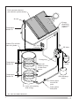
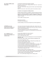
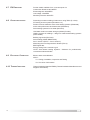
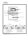
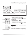
SOLARcomfort
Solar Hot Water
Systems
AST 100 Solar
Controller
Country of Destination GB/IE
Installation,
Commissioning and User
Instructions
LEAVE THESE INSTRUCTIONS WITH THE
END USER
TABLE OF CONTENTS
1.
1.1
1.2
1.3
1.4
1.5
1.6
GENERAL INFORMATION ...............2
GUARANTEE .......................................... 2
SYSTEM CONTENTS ................................ 2
SYSTEM INSTRUCTION BOOKS .................. 2
SOLARCOMFORT ................................. 3
LIFESTYLE ............................................ 3
HOW THE SYSTEM WORKS ....................... 3
2.
SAFETY ........................................... 4
3.
TECHNICAL DATA ...........................6
3.1 COMPONENT LIST .................................. 7
3.2 DIMENSIONS .........................................7
4.
4.1
4.2
4.3
4.4
4.5
4.6
4.7
4.8
4.9
4.10
REGULATIONS & STANDARDS ...... 8
WATER REGULATIONS .............................8
BUILDING REGULATIONS .......................... 8
GENERAL GUIDANCE ............................... 8
BRITISH & EUROPEAN STANDARDS ............ 9
UK REGULATIONS (WATER HEATING) ........ 9
UK REGULATIONS (CONSTRUCTION) ......... 9
EU DIRECTIVES ..................................10
OTHER PUBLICATIONS ...........................10
ELECTRICAL CONNECTION .....................10
THERMAL INSULATION ............................10
5.
5.1
5.2
5.3
5.4
5.5
5.6
5.7
5.8
5.9
5.10
OPERATION & FUNCTIONS .........11
CONTROLLER LAYOUT ...........................11
CONTROLLER FUNCTIONS ......................12
MENU OPTION & VALUE DISPLAY ............12
MENU NAVIGATION ...............................12
CONTROLLER SETTINGS ........................13
SYSTEM IMAGE ....................................14
SYSTEM IMAGE ICONS ...........................14
TOOL BAR .........................................15
OPERATING MODE HND1 & HND2 ......16
CONTROLLER SETTINGS ........................16
7.
COMMISSIONING SYSTEM .......... 21
7.1 INITIAL SETTING ................................... 21
7.2 OPTIONS FOR STANDARD SYSTEM
ARR 1 ............................................... 23
7.3 OPTIONS FOR SYSTEM WITH AUXILIARY HEAT
ARR 2 ............................................... 24
7.4 INFORMATION ONLY MENU OPTIONS .........25
7.5 SETUP PARAMETERS MENU OPTIONS .......27
8.
8.1
8.2
8.3
8.4
MAINTENANCE ............................. 32
FUSE REPLACEMENT ............................. 32
SENSOR FAILURE .................................32
CONTROLLER FAILURE ..........................32
FAULT FINDING .................................... 32
9.
9.1
9.2
9.3
9.4
9.5
USER INSTRUCTIONS ................. 35
CONTROLLER FUNCTIONS ......................35
MENU OPTION AND VALUE DISPLAY .........35
HOUSEHOLDER RESET OPTIONS .............35
HOW TO RESET COUNTERS ...................36
FAULT CONDITION ................................36
6.
6.1
6.2
6.3
6.4
INSTALLATION ...............................17
POSITIONING CONTROLLER ....................17
WALL MOUNTING CONTROLLER ..............17
ELECTRICAL CONNECTIONS ....................18
WIRING DIAGRAM STANDARD SYSTEM
ARR 1 ...............................................19
6.5 WIRING DIAGRAM SYSTEM WITH AUXILIARY
HEATING ARR 2 ..................................20
1
1.
GENERAL
INFORMATION
This manual is an integral and essential part of the product. It should be
kept with the product.
Please read carefully the instructions and notes about SOLARcomfort
contained in this manual as they provide important information regarding
the installation, commissioning and user instructions of the AST 100 Solar
Controller and the SOLARcomfort system.
IMPORTANT
Failure to follow these instructions correctly may invalidate the
guarantee.
IMPORTANT
Solar domestic hot water heating systems must be installed to
comply with the current Building Regulations, British Standards
and any applicable local regulations refer to section 5.
1.1 GUARANTEE
The SOLARcomfort AST100 Solar Controller is guaranteed for 2 years see terms and conditions of guarantee on back page.
1.2 SYSTEM CONTENTS
The complete SOLARcomfort solar water heating system is supplied in
the following consignments:-
1.3 SYSTEM INSTRUCTION BOOKS
2
1. 800201
Collector
1 per box
2. 3107024/5
Roof Fittings Kit
1 cardboard tube
3. 3820011/2
System Components
1 box
4. 3820001
Tyfocor antifreeze heat transfer fluid
1 x 20l container
The following instruction booklets are supplied with a complete
SOLARcomfort solar water heating system:1.
SOLARcomfort Solar Hot Water Systems Collectors 2 & 3 Collector
Set.
Covers collector installation and plumbing connection.
Supplied in System Components box.
2.
SOLARcomfort Solar Hot Water Systems Pump Group 40/60.
Covers installation, plumbing connection, system filling, flushing and
commissioning.
Supplied in System Components box.
3.
Solar Controller AST 100
Covers installation, wiring connection and User Instructions.
Supplied in System Components box.
1.4 SOLARCOMFORT
SOLARcomfort systems are highly efficient and provide cost savings on
the energy used for heating hot water wherever they are used in the UK.
However, the savings made will depend on local climate, installation
characteristics and the households use of hot water.
It is important that the SOLARcomfort system is correctly sized for the
local climate condition and the householders domestic hot water
requirements.
1.5 LIFESTYLE
After installation of the SOLARcomfort system, changes to the
householders use of hot water will be beneficial. Simple changes such as
bathing in the evening instead of the morning, and putting automatic
washing machines on when free hot water is available by solar energy.
In addition the timing of the dwelling’s boiler controls must be modified to
ensure the ‘hot water ON’ time is set so that the water temperature in the
cylinder is at a minimum by the start of the ‘solar day’.
1.6 HOW THE SYSTEM WORKS
See fig. 1.6A
The solar collectors are heated by the sun’s rays. The heat generated is
stored in a hot water storage cylinder e.g. an Ariston Primo twin coil stainless
steel cylinder. The AST 100 Solar Controller continually compares the
temperature of the water within the cylinder with the temperature of the
solar collectors.
Whenever the solar collectors are hotter than the water within the cylinder,
the controller switches on the system’s circulating pump. The temperature
differential between the collectors and the cylinder is set via the AST 100
Solar Controller. The heat transfer fluid within the solar system is then
circulated through the collectors and the cylinder’s heat exchanger, heating
the cylinder in just the same way as a central heating boiler.
The cylinder typically has two coils (heat exchangers), the lower coil is
heated by the solar system, therefore solar is the primary heat source.
The upper cylinder is heated by an auxiliary heat source, typically a central
heating boiler, which is used to heat water when there is insufficient heat
generated by the solar system. The Ariston Primo twin cylinder also has
two immersion heaters making it suitable for electric only heating systems.
The SOLARcomfort system is a forced circulation sealed system and
therefore requires an expansion vessel and a pressure relief valve (PRV),
both supplied with SOLARcomfort.
The air separator module with an integral air vent together with an automatic
air vent positioned at the highest point on the system ensures that the
sealed system remains free of air.
3
Roof mounted collectors
(two collector system shown)
Air vent
Energy
Monitoring
Sensor S4
(option)
Temperature
Sensor S1
Ariston ITSI 210/300
twin coil cylinder
AST 100
Controller
PR Valve
Pump group
Temperature
Sensor S3
Expansion
vessel
Upper coil
heated by boiler
or other heat
source
Temperature
Sensor S2
PRV discharge
vessel
Solar system
low level fill
point
Lower coil heated by
solar energy
FIG. 1.6A SOLAR BASIC PRINCIPLES
4
Solar system
drain point
2.
SAFETY
WARNING
All wiring should be carried out to and comply with the current IEE Wiring
Regulations.
All electrical work must comply with any relevant regulations that apply at
the time of the installation.
All electrical installation and maintenance of the AST 100 Controller must
be carried out by a competent qualified installer.
WARNING
TYFOCOR LS Heat Transfer Fluid.
Although non-toxic it should not be swallowed.
Refer to label on its container for storage and safety information.
A detailed technical specification is available from Ariston on request.
Caution
SOLARcomfort should be installed and commissioned by approved
contractors. Failure to do so may invalidate the warranty.
Caution
The controller should be positioned so that it is inaccessible to children
and cannot be tampered with.
5
3.
TECHNICAL DATA
CONTROLLER
Type
AST100
Housing
PC-ABS & PMMA
Dimensions
173 x 110 x 46
Mounting
Wall (2 screws)
Operation
3 Push Buttons
Protection
IP20 / DIN 40050
Environmental Temperature
0 - 40°C
FUNCTIONS
Temperature Differential Control
Standard
Operating Hours Counter
Standard
Energy Monitor
Option
ELECTRICAL
Power Supply
210-240V
Electromechanical Relay
250V
Controller Mains Cable
1.0mm² 3 core heat resistant flex 3093y
Pump Cable (R1 and R2)
1.0mm² 3 core heat resistant flex 3093y
SENSORS
6
Collector Sensor
S1
Cylinder lower
S2
Cylinder upper
S3
Energy monitor (collector return)
S4
3.1 COMPONENT LIST
Listed below are all the components supplied with the Controller.
Item
1
2
3
4
5
6
7
8
Description
Controller
Sensor - Collector
Sensor - Cylinder Upper
Sensor - Cylinder Lower
Spare Fuse - T4A
Cable Clips and screws
Fixing Screws
Wall Plug
Qty
1
1
1
1
1
4
2
2
FIG. 3.1A CONTROLLER COMPONENT LIST
3.2 DIMENSIONS
110
=
47
173
155
130
HANGING
POINT
104
=
FIXING
POINT
11
13
FIG. 3.2A CONTROLLER DIMENSIONS
7
4.
REGULATIONS &
STANDARDS
SOLARcomfort hot water heating systems should be installed in
compliance with the following standards and regulations.
4.1 WATER REGULATIONS
Water Supply (Water Fittings) Regulations 1999 / www.wras.co.uk
These regulations (bye-laws in Scotland) ensure a good supply of
wholesome water and that only approved materials, pipes and fittings are
used to convey water.
4.2 BUILDING REGULATIONS
These are statutory documents and take priority over all other regulations
and recommendations. The installation of an unvented hot water storage
cylinder is classified as a “Controlled Service” and Regulation G3 applies.
To meet the requirements of the Regulations, installation of an unvented
system should be undertaken by a “competent installer”.
All installations of unvented hot water storage systems having a capacity
of more than 15 litres should be notified to the relevant Local Authority by
means of building notice or by the submission of full plans. It is important
to note that it is a criminal offence to install an unvented hot water storage
system without notifying the Local Authority. The installation of the unvented
cylinder and hot water system must comply with BS 6700 and the HSE
Legionella Code of Practice.
4.3 GENERAL GUIDANCE
Current guidance notes do not cover the connection of a solar thermal
circuit to an unvented storage vessel (cylinder). However, if guidance is
sought for compliance with current regulations the fundamental principle
is to provide a fail-safe means of shutting off the solar input to the heat
exchanger if the cylinder temperature should rise above the set temperature
of the cylinder’s energy cut out. (See Note 1).
As with all unvented hot water systems, notification of intention to install
should be given to your local building control.
Option A. A non self-resetting mechanical shut-off should be installed on
the solar primary flow to the cylinder. The mechanical shut-off should be
suitable for use with a solar primary circuit (i.e. high temperature and glycol
resistant). The mechanical shut-off should be integrated electrically with
the cylinder energy cut out/s and if necessary the solar circuit temperature
control, please refer to the solar controller manufacturer for further
information.
Option B. Where the solar controller and hydraulic system demonstrate
that by no lesser means the requirement in Option A is satisfied by other
means; certification by an approvals body is required to demonstrate that
in the event of the stored water going over temperature, the heat input to
the cylinder is isolated by physical means and is non self-resetting.
These systems should be clearly identified with reference to the approvals
body. (See Note 2).
Note 1 : Whilst most solar cylinders use a coil type heat exchanger other
options such as external plate to plate devices, external annulars or ‘tank
in tank’ systems may be used but the same control options always apply.
Note 2 : Current approved bodies include the British Board of Agrèment
(BBA), WRc-NSF Limited, or KIWA.
8
4.4 BRITISH & EUROPEAN
STANDARDS
Connection of thermal solar heating systems
EN 12976: Thermal solar heating systems and their components
(prefabricated systems).
ENV 12977: Thermal solar heating system and their components (bespoke
systems).
BS5918: Latest version: Solar heating systems for domestic hot water.
Installation and equipment of DHW cylinders
BS5546: 2000 Specification for installation of hot water supplies for domestic
purposes, using gas-fired appliances of rated input not exceeding 70 kW.
BS6700: 1997 Specification for design, installation, testing and
maintenance, of servicing, supplying water for domestic use within buildings
and their curtilages.
The local water company by-laws.
Electrical connection
Current IEE wiring regulations.
Health and Safety document No 635 (Electricity at Work Regulations)
4.5 UK REGULATIONS
PARTICULARLY RELEVANT FOR
WATER HEATING EQUIPMENT
4.6 UK REGULATIONS
PARTICULARLY RELEVANT FOR
CONSTRUCTION
The Pressure Equipment Regulations (PED) 1999 - www.eurodyn.com
The Building Regulations (L1 A&B) 2006 and Domestic Heating Compliance
Guide - www.communities.gov.uk
The Building Regulations (P) 2005 - www.communities.gov.uk
Control of Substances Hazardous to Health Regulations (COSHH) 1994 www.hse.gov.uk
Further details available from: www.hse.gov.uk
Health & Safety At Work Act (HSW) 1974
Work at Height Regulations 2005.
Reporting of Injuries, Diseases and Dangerous Occurrences Regulations
(RIDDOR) 1995.
Management Health & Safety at Work Regulations (MHSWR) 1999.
Noise at Work Regulations 1989.
Construction (Health, Safety & Welfare) Regulations (CHSWA) 1996.
Electricity at Work Regulations 1989.
Construction Regulations (Head Protection) 1989.
Control of Substances Hazardous to Health Regulations (COSHH) 1994.
Construction (Design and Management) Regulations (CDM) 1994.
Personal Protective Equipment at Work Regulations 1992.
Lifting Operations and Lifting Equipment Regulations (LOLER) 1998.
Confined Spaces Regulations 1997.
Manual Handling Operations Regulations 1992.
The Workplace (Health, Safety and Welfare) Regulations 1992 (WHSWA).
Provision and Use of Work Equipment Regulations (PUWER) 1998.
Health and Safety (First Aid) Regulations 1981.
LZC - Low or zero carbon energy sources: strategic guide.
9
4.7 EU DIRECTIVES
Further details available from: www.europa.eu.int
Construction Directive: 89/106/EEC
Electromagnetic: 89/336/EEC
Low voltage: 73/23/EEC
Machinery Directive: 98/37/EC
4.8 OTHER PUBLICATIONS
Preventing hot water scalding in bathrooms: using TMVs (IP 14/03).
DTI testing of solar systems (SP300275 1-3).
Review of issues related to active solar heating systems (SP300246).
Active solar performance and data review (SP300270).
Solar heating systems for hot water (BS 5918).
Hard water scale in hot water storage cylinders (IP13/93).
Heating systems in buildings – design for water-based heating systems
(PrEN 12828).
Building log books (GPG 348).
Solar heating (CIBSE DBSP WGG).
Sun in Action II (ESTIF – Sun in Action II).
Minimising the risk of legionnaires’ disease (TM 13).
BRE Digest 489.
Energy Saving Trust - www.est.org.uk
CE131 Solar Water Heating Systems - Guidance for professionals,
conventional Indirect Models.
4.9
BS7671 2001 Amended 2004
APD P:
P1 - Design, Installation, Inspection and Testing
P2 - Provision of information
ELECTRICAL CONNECTION
4.10 THERMAL INSULATION
10
Thermal Insulation Standard TIMSA (Thermal Insulation Manufacturers and
Suppliers Association).
5. OPERATION &
FUNCTIONS
5.1 CONTROLLER LAYOUT
Display
°C
AST 100
Indicator light
Backward
button
Forward button
Set button
Cover retaining screw
Cable entry through
bottom only
Arr 1 (default)
Typical operating display for
standard system.
(The cylinder can be either a twin coil or
a single coil buffer type, controlled by
AST 100 Controller)
Arr 2
Typical operating display for
system with auxiliary heat
source control.
(Upper coil shown only when it is
controlled by AST 100 Controller R2)
FIG. 5.1A AST 100 CONTROLLER
11
5.2 CONTROLLER FUNCTIONS
INDICATOR
LIGHT
AST 100
Indicator Light
Off
No power to the SOLARcomfort controller.
Green
Power is On - normal condition.
Red/Green flashing
Initialisation phase.
HND1 or HND2 are set to On.
Red flashing
Fault condition. Indicates one of the sensors is
defective or not connected. Also a sensor symbol
on the display will flash rapidly indicating which
sensor is causing fault - see 5.7.
BACKWARD
SET
FORWARD
The contoller is operated by three push buttons situated below the display.
Forward Button
Use to scroll forward through menu options on the display.
Use to increase the value of a menu option when
is displayed.
Backward Button
Use to scroll backward through menu options on the display.
Use to decrease value of a menu option when
is displayed.
Set Button
Use to change and save, or zero menu option settings.
5.3 MENU OPTION AND VALUE
DISPLAY
Menu Option
Displays the option selected using the forward
buttons.
Menu option
°C
Value
Example shown menu option ‘COL’
and backward
Value
Displays the current set value for the menu option selected.
When
is also displayed it indicates that the value can be changed or
set to zero using the set button - refer to Section 5.5.
IMPORTANT
Menu options are set during commissioning and should not be
changed by the householder without first contacting the installer.
5.4 MENU NAVIGATION
The SOLARcomfort controller has two levels of menu options, information
only and setup parameters.
When power is switched on to the controller it goes through an initialisation
phase and then shows the first of the ‘infomation only’ options (COL).
The forward
and backward
buttons can then be used to index
through the ‘information only’ options.
button to reach the
To access the ‘setup parameters’ use the forward
last ‘infomation only’ option, then press and hold the forward
button
until the first of the ‘setup parameters’ is shown (Arr).
The forward
and backward
through the ‘setup parameters’.
12
buttons can then be used to index
The backward
button indexes the options back from the ‘setup
parameters’ through to the ‘infomation only’ options. From here the ‘system
setup parameters’ has to be accessed again by pressing and holding the
forward
button at the last ‘display only’ option.
°C
Information only options
Setup parameters
COL
hP
Arr
VERS
First
Last
First
Last
BACKWARD
FORWARD
Press
and hold
BACKWARD
FORWARD
FIG. 5.4A MENU NAVIGATION
5.5 CONTROLLER SETTINGS
To change the menu option settings:1. Navigate to the required menu option - see above.
If the menu option can be changed or reset
displayed.
INDICATOR
LIGHT
AST 100
BACKWARD
will also be
TO CHANGE A VALUE
2.
3.
Press and hold set button until
flashes.
The current setting will be displayed.
Record current value so value is not forgotten.
Press forward button to increase value or backward button to decrease
value.
4.
Press and hold set button again until
The new value will now be saved.
SET
FORWARD
stops flashing.
TO RESET A VALUE
Menu option
2.
3.
Value
Press and hold set button until
flashes, the value will be reset
to 0.
To confirm press set again until it stops flashing.
To interrupt reset or change procedure, do not press any button for
about 5 seconds and the controller option will return to previous setting.
Example shown menu option ‘Arr’
13
There are two operating displays for SOLARcomfort, which one is shown
depends on the setting for setup parameter option ‘Arr’:-
5.6 SYSTEM IMAGE
Note:‘Arr’ is set on commissioning to
suit the installed system and
should not be changed - see 7.1.
1.
Standard system for twin or single coil cylinders - Arr 1.
Only bottom coil is controlled by AST 100 (R1).
2.
System with auxiliary heat source control - Arr 2.
Both coils are controlled by AST 100 (R1 & R2).
Arr 1 (default)
Arr 2
Typical operating display for
standard system
Typical operating display for
system with auxiliary heat
source control
FIG. 5.5A DISPLAY FOR SETTINGS ARR 1 AND ARR 2
5.7 SYSTEM IMAGE ICONS
Collector (with sensor)
Cylinder with heat exchanger
Cylinder icon will either show:one heater exchanger control when Arr 1 is selected, or
two heat exchanger controls when Arr 2 is selected.
Arr 1
Arr 2
Auxiliary heat source with burner symbol.
Only displayed when Arr 2 is selected.
Temperature Sensors
Icons for S1, S2 and S3 flash when the following options are selected from
the information only menu:Arr 1
S1 flashes when COL is selected - Collector temperature
S2 flashes when TST is selected - Lower cylinder temperature
S3 flashes when S3
is selected - Upper cylinder temperature
S1
S3
S2
Arr 1 shown
14
Arr 2
S1 flashes when
S2 flashes when
S3 flashes when
COL is selected - Collector temperature
TSTL is selected - Lower cylinder temperature
TSTU is selected - Upper cylinder temperature
When icons flash rapidly it indicates a fault with the relevant sensor, or that
the sensor is not connected - consult engineer.
Solar Pump
Shown in pipework to collectors.
Flashes when solar pump is running (R1 On).
Auxiliary Heating Pump Arr 2 only
Shown in pipework to auxiliary heat source.
Flashes when auxiliary pump is running (R2 On).
5.8 TOOL BAR
The tool bar icons show the current system status.
Icon
Sta tus
Indica tion
On
Rela y R1 ena bled - s ola r pump On
On
Rela y R2 ena bled - a ux. pump On
On
Set ma ximum s tore limit 'S MX' tempera ture exceeded
(only when recooling 'OREC' is Off)
Fla s hing
Sy s tem cooling 'OCX' s et to On
a nd pump is running to cool s y s tem to s et CMX va lue.
On
Antifreeze function 'OCF' s et to On
Fla s hing
Recooling function 'OREC' s et to On.
Or - Minimum collector temp function 'OCN' is On a nd
collector temp is below s et minimum collector temp
'CMN'.
Or - Antifreeze function 'OCF' is s et to ON a nd collector
temp. is below s et a ntifreeze tempera ture 'CFR'.
Fla s hing
Collector s ecurity s hutdown a ctive i.e:Set emergency collector temp 'EM' ha s been exceeded.
Or - Cy linder s ecurity s hutdown a ctive i.e:Ma ximum cy linder temp 'S MX' ha s been exceeded
Fla s hing
Sens or defect or not connected, releva nt s ens or icon a ls o
fla s hes ra pidly
Fla s hing
On
Fla s hing
Ma nua l opera tion 'HND' or 'HND 2 ' s et to On
Dis pla y ed menu option va lue ca n be cha nged or s et to
zero us ing s et button
Va lue ha s been cha nged, pres s s et button to s a ve.
15
5.9 OPERATING MODE HND1 &
HND2
Solar pump icon
Auxiliary heat
source pump icon
Arr 1
When HND1 and/or HND2 are set to On or Off the following icons will be
displayed flashing
HND 1
Set to Auto - Normal operation.
Set to On - Relay R1 On - solar pump running - pump icon flashes.
Set to Off - Relay R1 Off - solar pump not running - pump icon not
flashing.
HND 2
Set to Auto - Normal operation.
Set to On - Relay R2 On - auxiliary heat pump running - pump icon
flashes.
Set to Off - Relay R2 Off - auxiliary heat pump not running - pump icon
not flashing.
Arr 2
5.10 CONTROLLER SETTINGS
On power up the controller will go through an initialisation phase during
which the operating control light flashes red then green.
The controller then shows the system image display see 5.6.
To display menu options use forward button to scroll forward and back
button to scroll backwards.
INDICATOR
LIGHT
AST 100
BACK
To change the menu option settings:1. Press forward button to scroll through to required option.
If the menu option can be changed or reset
SET
will also be displayed.
TO CHANGE A VALUE
FORWARD
2.
3.
Press and hold set button until
flashes.
The current setting will be displayed.
Record current value so value is not forgotten.
Press forward button to increase value or back button to decrease
value.
4.
Press and hold set button again until
The new value will now be saved.
Menu option
stops flashing.
TO RESET A VALUE
Value
2.
Press and hold set button until
to 0.
3.
To confirm press
flashes, the value will be reset
Example shown menu option ‘Arr’
again until it stops flashing.
To interrupt reset or change procedure, do not press any button for about
5 seconds and the counter will return to previous setting.
16
6.
INSTALLATION
The pump module and air separator modules should normally be wall mounted
in close proximity to the cylinder.
6.1 POSITIONING CONTROLLER
Fig. 6.1A gives a typical layout.
The AST 100 Solar Controller should be positioned so that the householder
has easy access with good visibility of the display. Also, consideration has
to given to routing for connection to the pump module, cylinder and collector
temperature sensors.
Cables supplied with the sensors and control unit are nominal length and
may require terminal boxes and extra cable lengths to make connections.
The controller should be positioned so that it is inaccessible to children
and cannot be tampered with.
To Collector
Temperature
Sensor S1
From Collectors
To Collectors
AST 100
Controller
Expansion
Vessel
Cylinder
S3
Fill point
Pump
Group
S2
PRV
discharge
vessel
FIG. 6.1A SUGGESTED LOCATION
6.2 WALL MOUNTING
CONTROLLER
The controller is wall mounted with two screws. The upper screw is used
to hang the unit on, the lower screw is used to fix the unit to the wall - see
fig. 4.2A.
Two wall plugs and screws are supplied.
17
6:3 ELECTRICAL CONNECTIONS
All wiring should be carried out to and comply with the current IEE
Wiring Regulations.
All electrical work must comply with any relevant regulations that
apply at the time of the installation.
All electrical installation and maintenance of SOLARcomfort must be
carried out by a competent qualified installer.
DO NOT drill casing for cable entry.
1.
2.
3.
4.
5.
All cable sheath clamps must be correctly fitted.
The conductor sheaths must be continuous into joint enclosures.
Conductors must be correctly fastened to terminals.
Conductor insulation to be within 2mm of terminals.
All cable conductors external to joint enclosures must be insulated
and sheathed.
MAINS SUPPLY
The mains supply must be from a fused double pole isolating switch fitted
with 5 amp fuse or a BS1383/A kite marked domestic plug fitted with 5
amp fuse.
IMPORTANT
The mains supply cable must be separated from the sensor cables by
a minimum of 15mm.
ELECTROMECHANICAL RELAYS
The SOLARcomfort controller incorporates two standard electromechanical
relays which have a breaking capacity of 2(1)A 250V~.
AUXILIARY HEAT SOURCE PUMP
When the AST 100 is installed with an auxiliary heat source (and set as
Arr 2), the pump for this is wired to the controller (R2) - see wiring diagram
6.5B.
The auxiliary pump must not be set at maximum speed.
ARISTON PRIMO TWIN CYLINDERS
When using an Ariston Primo twin cylinder the following must be done:Note: All makes of cylinders with a
manual reset overheat thermostat
have to be connected in the same
way.
18
1.
The lower cylinder temperature thermostat must be completely
removed.
2. The manual reset overheat thermostat must be wired as shown on
wiring diagram Fig. 6.4A.
3. The AST 100 sensor S1 must be inserted into the cylinder’s lower
temperature sensor pocket together with the overheat temperature
sensor.
For other makes and models of cylinder, please refer to the
manufacturer’s instructions.
6.4 WIRING DIAGRAM
STANDARD SYSTEM - Arr 1
IMPORTANT
The mains supply cable must be
separated from the sensor cables by a
minimum of 15mm.
Collector
S1 Collector
Sensor
Arr 1
Collector
S4 Energy
Monitoring
Sensor (option)
FUSE 4A
Temp. Sensor
Pt1000
6
7
S4
N R2 N R1 N L
12 13 14 15 16 17 18 19 20
8
g/y
blue
S3
brown
5
brown
4
blue
S2
blue
3
brown
2
g/y
S1
g/y
1
R1 2(1)A 220-240V~
1.0mm² 3 core
heat resistant
flex 3093y
1.0mm² 3 core
heat resistant
flex 3093y
BS 1383/A kite marked
Domestic Plug - fused 5A
or
Double Pole Isolating
Switch fused 5A (as shown)
Cylinder
brown
blue
FUSE 5A
g/y
Mains Supply
220-240V
S3 Upper
Sensor
Cylinder
Manual Reset
Overheat
Stat NC
blue
g/y
L N
brown
S2 Lower
Sensor
SOLARcomfort Pump
(Pump Module)
1.0mm² 3 core heat resistant flex 3093y
FIG. 6.4A WIRING DIAGRAM - STANDARD SYSTEM
19
6.5 WIRING DIAGRAM
SYSTEM WITH AUXILIARY HEATING - Arr 2
IMPORTANT
The mains supply cable must be
separated from the sensor cables by a
minimum of 15mm.
Arr 2
S1 Collector Sensor
Collector
Collector
S4 Energy
Monitoring
Sensor (option)
FUSE 4A
Temp. Sensor
Pt1000
7
S4
8
N R2 N R1 N L
12 13 14 15 16 17 18 19 20
R1 2(1)A 220-240V~
R2 2(1)A 220-240V~
brown
6
blue
S3
blue
5
brown
4
brown
S2
blue
3
g/y
2
g/y
S1
g/y
1
1.0mm² 3 core
heat resistant
flex 3093y
BS 1383/A kite marked
Domestic Plug - fused 5A
or
Double Pole Isolating
Switch fused 5A (as shown)
1.0mm² 3 core
heat resistant
flex 3093y
Cylinder
brown
FUSE 5A
blue
g/y
Mains Supply
220-240V
S3 Upper
Sensor
Cylinder
Manual Reset
Overheat
Stat NC
SOLARcomfort Pump
(Pump Module)
N
blue
L
brown
g/y
S2 Lower
Sensor
g/y
N
blue
L
brown
Auxiliary Heat
Source Pump
1.0mm² 3 core heat resistant flex 3093y
FIG. 6.5A WIRING DIAGRAM
20
7.
COMMISSIONING
CONTROLLER
7.1 INITIAL SETTING
IMPORTANT
Note To change the system settings
see 5.5.
IMPORTANT
To set up the AST 100 Controller the following conditions must exist:1. Mains lead connected to 220 - 240V fused 5 amp supply.
2. Sensor S1 connected.
3. Sensor S2 connected.
4. Sensor S3 connected.
5. Sensor S4 connected (option).
On power up the controller will go through an initialisation phase during
which the operating control light flashes red then green.
OTC FUNCTION
During commissioning the OTC function must be set to ON, this runs
the pump briefly to achieve accurate temperature detection.
SYSTEM Arr 1 or 2
The first time the controller is powered up the default setting will be for a
standard system (Arr 1).
Setting Arr 1 or Arr 2 determines which set of options are available on the
display - see tables 7.2 and 7.3.
Arr 1 or Arr 2 must be set on commissioning to suit the system
installed.
THE SETTING MUST NOT BE CHANGED THEREAFTER.
Arr 1
Arr 1 is used when only one cylinder heat exchanger coil is controlled
by the AST 100 Controller, i.e. solar system is circulated through the coil
by the solar pump controlled by R1 - see wiring diagram fig. 6.4A.
The cylinder may be a two coil cylinder or single coil buffer type, however
any components or system, other than the SOLARcomfort, connected to
the cylinder are NOT controlled by the AST 100.
Arr 1
Solar
Pump
FIG. 7.1A ARR 1
21
Arr 2
Arr 2 is used for two coil cylinders when the use of both the upper and
lower coils of the cylinder are controlled by the AST 100 Controller (R1
& R2).
There are two ways that this can be done:-
IMPORTANT
*Some boilers with integral
circulating pumps are not suitable
for this application - consult Ariston
for further details.
IMPORTANT
1. Arr 2 Auxiliary Heat Source
The lower solar coil is controlled by the AST 100 Controller, i.e. solar
system is circulated through the lower coil by the solar pump controlled
by R1 - see wiring diagram fig. 6.4A.
*The cylinder upper coil is heated by an auxiliary heat source, this is
also controlled by the AST 100 Controller i.e. the auxiliary heat source
circulating pump is controlled by R2 - see wiring diagram fig. 6.5A.
The pump is switched On by AHO and Off by AHF - see 7.5.20 & 7.5.21.
When Arr 2 is selected extreme care must be taken to ensure the
auxiliary heat source only operates when it will not adversely affect
the cylinder temperature prior to and during the ‘solar day’.
2. Arr 2 Heat Circulating
The lower solar coil is controlled by the AST 100 Controller, i.e. solar system
is circulated through the lower coil by the solar pump controlled by R1 - see
wiring diagram fig. 6.4A.
The upper coil is used to heat a radiator when there is ample or excessive
solar energy. For this a pump is fitted controlled by R2 - see wiring
diagram fig. 6.5A.
The pump is switched On by AHO and Off by AHF - see 7.5.20 & 7.5.21.
Arr 2 Auxiliary Heat Source
Aux heat
source pump
Solar
pump
Arr 2 Heat Circulating
Solar
pump
Heat circulating pump
FIG. 7.1A ARR 2 OPTIONS
IMPORTANT
22
Arr 2 is only used for more advanced systems, the installer must
have full appreciation of the system and the way the AST 100
Controller settings affect the auxiliary heat source or heat circulating
system.
7.2 OPTIONS FOR STANDARD
SYSTEM Arr 1
Quick reference only, for further
details see 7.4 and 7.5
The following menu options will be available when Arr is set to 1 - see 7.1
Set ‘X’
indicates value is display only.
Set ‘✓ ‘
*indicates value can be changed using set button.
Set ‘reset’ *indicates value can be reset using set button.
*
MENU
OPTION
SET
C OL
X
TST
S3
TRF
hP
will be displayed on screen
RANGE
DEFAULT
SETTING
SET
VALUE
REFER TO:-
C o l l e c t o r Te m p e r a t u r e as detected by sensor S1
- 40°C to +250°C
-
-
7.4.1
X
Lo w e r C y l i n d e r Te m p e r a t u r e as detected by sensor S2
- 40°C to +250°C
-
-
7.4.2
X
U p p e r C y l i n d e r Te m p e r a t u r e as detected by sensor S3
- 40°C to +250°C
-
-
7.4.3
X
C o l l e c t o r R e t u r n Te m p e r a t u r e as detected by sensor S4
Only displa yed when OHQM is set t o On
- 40°C to +250°C
-
-
7.4.4
DESCRIPTION
reset
O pe rat i n g H ou rs C ou n t e r
-
-
-
7.4.5
kW h
reset
H e at ge n e rat e d - k W pe r h ou r
Only displa yed when OHQM is set t o On
-
-
-
7.4.6
MW h
reset
H e at ge n e rat e d - MW h pe r h o u r
Only displa yed when OHQM is set t o On
-
-
-
7.4.6
1
7.5.1
P R E S S A N D H O L D F O R W A R D B U T T O N T O A C C E S S S E T U P P A R A M E T E R S M E N U O P T I O N S B E LO W
Arr
✓
S y s t e m a r r a n g e m e n t 1 = standard system
Arr 1 or Arr 2
1
DT O
✓
S ol ar pu mp sw i t c h O n t e mpe rat u re di f f e re n t i al .
1.0 to 20.0K
6.0K
7.5.2
DT F
✓
S ol ar pu mp sw i t c h O f f t e mpe rat u re di f f e re n t i al .
0.5K to 19.5K
4.0K
7.5.3
S MX
✓
M a x i m u m C y l i n d e r Te m p e r a t u r e .
2°C to 95°C
60°C
7.5.4
EM
✓
M a x i m u m C o l l e c t o r Te m p e r a t u r e (emergency shutdown)
110°C to 200°C
140°C
7.5.5
OC X
✓
Syst e m C ool i n g ( C o l l e c t o r)
OFF or ON
OFF
7.5.3
✓
S y s t e m C o o l i n g Te m p e r a t u r e ( C o l l e c t o r )
Only a c t ive when OC X is set t o ON
100°C to 190°C
120°C
7.5.6
✓
M i n i m u m C o l l e c t o r Te m p e r a t u r e
OFF or ON
OFF
7.5.7
✓
M i n i m u m C o l l e c t o r Te m p e r a t u r e
Only a c t ive when OC N is set t o ON
- 10°C to 90°C
10°C
7.5.7
✓
A n t i f re e ze F u n c t i o n
OFF or ON
OFF
7.5.8
✓
A n t i f r e e z e Te m p e r a t u r e
Only a c t ive when OC F is set t o ON
- 10°C to 10°C
4.0°C
7.5.8
OREC
✓
Re - c ool i ng Func t i on
OFF or ON
OFF
7.4.9
O TC
✓
C o l l e c t o r Te m p e r a t u r e M o n i t o r i n g F u n c t i o n
OFF or ON
ON
O HQ M
✓
En e rgy me asu re me n t
OFF or ON
OFF
7.5.11
FMAX
✓
S y s t e m F l o w R a t e - enter current setti ng
Only a c t ive when OHQM is set t o ON
0 to 6.0l/ mi n
6.0l/ mi n
7.5.12
MEDT
✓
A n t i f r e e z e Ty p e .
Only a c t ive when OHQM is set t o ON
0,1,2 or 3
1
7.5.13
MED%
✓
C o n c e n t r a t i o n o f a n t i f r e e z e ( Vo l % )
Only a c t ive when OHQM is set t o ON
20 to 70%
45
7.5.14
HN D 1
✓
O p e r a t i n g M o d e o f R 1 (Manual operati on of solar pump)
OFF,
AUTO or ON
AUTO
7.5.15
HN D 2
✓
O p e r a t i n g M o d e o f R 2 (Manual operati on of R2)
Not used on Ar r 1 syst em
OFF,
AUTO or ON
AUTO
7.5.16
LANG
✓
L a n g u a g e dE=German, En=Engli sh, It=Itali an
dE,En or It
En
7.5.17
PROG
-
P rogramme N u mbe r
-
-
7.5.18
VERS
-
Ve r s i o n N u m b e r
-
-
7.5.19
CMX
OC N
CMN
OC F
CFR
ON
7.5.10
23
7.3 OPTIONS FOR SYSTEM WITH
AUXILIARY HEAT Arr 2
Quick reference only, for further
details see 7.4 and 7.5
The following menu options will be available when Arr is set to 1 - see 7.1
Set ‘X’
indicates value is display only.
Set ‘✓ ‘
*indicates value can be changed using set button.
Set ‘reset’ *indicates value can be reset using set button.
*
MENU
OPTION
SET
C OL
X
TSTL
will be displayed on screen
RANGE
DEFAU LT
SETTING
SET
VALU E
REFER TO:-
C o l l e c t o r Te m p e r a t u r e a s detected by s ens or S1
-4 0 ° C to + 2 5 0 ° C
-
-
7 .4 .1
X
Lo w e r C y l i n d e r Te m p e r a t u r e a s detected by s ens or S2
-4 0 ° C to + 2 5 0 ° C
-
-
7 .4 .2
TSTU
X
U p p e r C y l i n d e r Te m p e r a t u r e a s detected by s ens or S3
-4 0 ° C to + 2 5 0 ° C
-
-
7 .4 .3
S4
X
C o l l e c t o r R e t u r n Te m p e r a t u r e a s detected by s ens or S4
Onl y di spl ayed when OHQM i s set to On
-4 0 ° C to + 2 5 0 ° C
-
-
7 .4 .4
DESC RIPTION
hP1
r es et
O p e r a t i n g H o u r s C o u n t e r - Sola r Pump (R1 )
-
-
-
7 .4 .5
hP2
r es et
O p e r a t i n g H o u r s C o u n t e r - Auxilia ry Pump (R2 )
-
-
-
7 .4 .5
kWh
r es et
H e a t ge ne r a te d - kW pe r hour
Onl y di spl ayed when OHQM i s set to On
-
-
-
7 .4 .6
MWh
r es et
H e a t ge ne r a te d - M W h pe r hour
Onl y di spl ayed when OHQM i s set to On
-
-
-
7 .4 .6
2
7 .5 .1
P R E S S A N D H O L D F O R W A R D B U T T O N T O A C C E S S S E T U P P A R A M E T E R S M E N U O P T I O N S B E LO W
Arr
✓
S y s t e m a r r a n g e m e n t 2 = a uxilia ry hea t s ource s y s tem
Arr 1 or Arr 2
2
DT O
✓
S ola r pum p s w i tc h O n te m pe r a tur e di ffe r e nti a l.
1 .0 to 2 0 .0 K
6 .0 K
7 .5 .2
DT F
✓
S ola r pum p s w i tc h O ff te m pe r a tur e di ffe r e nti a l.
0 .5 K to 1 9 .5 K
4 .0 K
7 .5 .3
S MX
✓
M a x i m u m C y l i n d e r Te m p e r a t u r e .
2 ° C to 9 5 ° C
60°C
7 .5 .4
EM
✓
M a x i m u m C o l l e c t o r Te m p e r a t u r e (emergency
s hutdown)
1 1 0 ° C to 2 0 0 ° C
140°C
7 .5 .5
OC X
✓
Sy s te m C ooling (C olle c tor )
OFF or ON
OFF
7 .5 .3
✓
S y s t e m C o o l i n g Te m p e r a t u r e ( C o l l e c t o r )
Onl y acti ve when OC X i s set to ON
1 0 0 ° C to 1 9 0 ° C
120°C
7 .5 .6
✓
M i n i m u m C o l l e c t o r Te m p e r a t u r e
OFF or ON
OFF
7 .5 .7
✓
M i n i m u m C o l l e c t o r Te m p e r a t u r e
Onl y acti ve when OC N i s set to ON
-1 0 ° C to 9 0 ° C
10°C
7 .5 .7
✓
Antifr e e z e Func tion
OFF or ON
OFF
7 .5 .8
✓
A n t i f r e e z e Te m p e r a t u r e
Onl y acti ve when OC F i s set to ON
-1 0 ° C to 1 0 ° C
4 .0 ° C
7 .5 .8
OREC
✓
Re - c ooling Func tion
OFF or ON
OFF
7 .4 .9
OTC
✓
C o l l e c t o r Te m p e r a t u r e M o n i t o r i n g F u n c t i o n
OFF or ON
ON
AH O
✓
T h e r m o s t a t S w i t c h O n Te m p e r a t u r e
0 .0 to 9 5 .0 ° C
4 0 .0 ° C
AH F
✓
T h e r m o s t a t S w i t c h O f f Te m p e r a t u r e
0 .0 to 9 5 .0 ° C
4 5 .0 ° C
O HQ M
✓
Ene r gy m e a s ur e m e nt
OFF or ON
OFF
7 .5 .1 1
FMAX
✓
S y s t e m F l o w R a t e - enter current s etting
Onl y acti ve when OHQM i s set to ON
0 to 6 .0 l/min
6 .0 l/min
7 .5 .1 2
MEDT
✓
A n t i f r e e z e Ty p e .
Onl y acti ve when OHQM i s set to ON
0 ,1 ,2 or 3
1
7 .5 .1 3
MED%
✓
C onc e ntr a ti on of a nti fr e e z e (V ol %)
Onl y acti ve when OHQM i s set to ON
2 0 to 7 0 %
45
7 .5 .1 4
HN D 1
✓
O p e r a t i n g M o d e o f R 1 (Ma nua l opera tion of s ola r pump)
OFF,
AU TO or ON
AU TO
7 .5 .1 5
HN D 2
✓
O p e r a t i n g M o d e o f R 2 (Ma nua l opera tion of a ux. pump)
OFF,
AU TO or ON
AU TO
7 .5 .1 5
LANG
✓
L a n g u a g e dE= Germa n, En= Englis h, It= Ita lia n
dE,En or It
En
7 .5 .1 7
PROG
-
P r ogr a m m e N um be r
-
-
7 .5 .1 8
VERS
-
V e r s i on N um be r
-
-
7 .5 .1 9
C MX
OC N
C MN
OC F
C FR
ON
7 .5 .1 0
Refer to 7 .5
24
7.4
INFORMATION ONLY MENU
OPTIONS
Note
Options that display
can be
set to zero - for procedure see 5.5.
COL
# # . # °C
The following menu options are display only.
When power is switched on to the controller it goes through an initialisation
phase and then shows the first of the ‘information only’ options (COL).
The forward
and backward
buttons can then be used to index
through the ‘information only’ options.
7.4.1 COL Collector Temperature
Range -40°C to +250°C - Display Only
Temperature of the collector flow as detected by sensor S1.
Only displayed when a sensor is connected to S1.
IMPORTANT
OTC option must be set to ON to ensure a correct temperature reading
is obtained.
Only when Arr is 1
TST
# # °C
Only when Arr is 2
TSTL
# # °C
Only when Arr is 1
S3
# # °C
Only when Arr is 2
TSTU
# # °C
Arr1 Only when OHQM is On
TRF
# # °C
Arr 2 Only when OHQM is On
S4
# # °C
Only when Arr is 1
hP
# # °C
Only when Arr is 2
hP1
###
7.4.2 TST, TSTL Lower Cylinder Temperature
Range -40°C to +250°C - Display Only
TST is displayed when Arr 1 is set.
TSTL is displayed when Arr 2 is set.
Temperature of the cylinder as detected by lower cylinder sensor S2.
Only displayed when a sensor is connected to S2.
7.4.3 S3, TSTU Lower Cylinder Temperature
Range -40°C to +250°C - Display Only
S3
is displayed when Arr 1 is set.
TSTU is displayed when Arr 2 is set.
Temperature of the cylinder as detected by upper cylinder sensor S3.
Only displayed when a sensor is connected to S3.
7.4.4 S4, TRF Panel Return Temperature (option)
Range -40°C to +250°C - Display Only
Arr 1
TRF is displayed when Energy Monitoring function OHQM is On.
Arr 2
S4
is displayed when Energy Monitoring function OHQM is On.
Temperature of the collector return as detected by sensor S4.
Only displayed when a sensor is connected to S4.
7.4.5 hP, hP1, hP2 Operating Hours Counter
Display Only
Arr 1
hP
Displays the total hours solar has operated as defined by relay R1 Solar pump ON time.
Arr 2
hP1 Displays the total hours solar has operated as defined by relay R1 Solar pump ON time.
25
Only when Arr is 2
hP2
hP2 Displays the total hours auxiliary heat source has operated as
defined by relay R2 - Auxiliary pump ON time.
###
Only when OHQM is On
KWh
##
Only when OHQM is On
MWh
##
7.4.6 KWh and MWh Energy Monitoring
Display Only
These options are only shown when Energy Monitoring OHQM function is
set to ON and a sensor S4 is connected to the collector return pipework.
The heat quantity transported is determined from :1. The flow volume, as set by ‘FMAX’
2. The flow temperature of the collector, as detected by sensor S1.
3. The return temperature, as detected by sensor S4 (TRF).
The sum of both menu option KWh + MWh equals the total heat output.
Example
MWh = 45
KWh = 750
45,000 + 750 = 45,750kW/h or 45.750MWh
26
7.5
SETUP PARAMETERS MENU
OPTIONS
Note
Options that display
can be
set changed - for procedure see
5.5.
Arr
1
Arr
2
To access the ‘setup parameters’ use the forward
button to reach the
last ‘information only’ option, then press and hold the forward
button
until the first of the ‘setup parameters’ is shown (Arr).
The forward
and backward
through the ‘setup parameters’.
buttons can then be used to index
7.5.1 Arr System Arrangement
Range - Arr 1 or Arr 2 ~ Default Arr 1
Arr 1
Arr 2
FIG. 7.5A ARR 1 AND ARR 2 SYSTEM ARRANGEMENTS
Arr 1 Sets the system for solar only heating control.
Only setup parameters for standard system will be shown.
Arr 2 Sets the system for solar and auxiliary heat source or heat
circulating control.
Only setup parameters for system with auxiliary heat source or
heat circulating will be shown.
Relay R2 is used for auxiliary source or heat circulating pump.
IMPORTANT
Arr 1 or Arr 2 must be set on commissioning to suit the system
installed.
THE SETTING MUST NOT BE CHANGED THEREAFTER.
DT O
# #. #
7.5.2 DT O Solar Pump Switch ON Temperature Differential
Range - 1.0K to 20.0K ~ Default 6.0K
The collector temperature as detected by S1 minus the cylinder temperature
as detected by S2 equals the solar temperature differential.
Solar Temperature Differential = S1 temp. - S2 temp.
The solar pump is switched On (R1 On) when the solar temperature
differential exceeds the set DT O value.
When ‘COL’ S1 temp. - S2 temp. > DT O R1 is On.
DT O recommended setting = 6°C
DT O must be at least 1°C above set DT F value.
DT F
4.0K
7.5.3 DT F Solar Pump Switch OFF Temperature Differential
Range - 0.5K to 19.5K ~ Default 4.0K
Also see DT O 7.5.2.
The solar pump is switched Off (R1 Off) when the solar temperature
differential is below the set DT F value.
When ‘COL’ S1 temp. - S2 temp. < DT F R1 is Off.
DT F recommended setting = 4°C
DT O must be at least 1°C below set DT O value.
27
S MX
4.0°K
7.5.4 S MX Maximum Cylinder Temperature
Range - 0.5K to 19.5K ~ Default 4.0K
S MX is the maximum temperature the cylinder is allowed to reach.
In the event of the set S MX value being exceeded, further heating of the
cylinder is prohibited by switching R1 Off (solar pump stopped).
will be displayed.
The S MX setting is overridden when, OCX is set to On and/or OREC is
set to On - see 7.5.6 & 7.5.9.
EM
140°C
7.5.5 EM Maximum Collector Temperature
Range - 110°C to 200°C ~ Default 140°C
EM is the emergency shut down temperature of the collectors, designed to
prevent damage to the solar components due to overheating.
When a temperature higher than the set EM value is detected by sensor
S1 the solar pump will be switched Off (R1 Off).
will flash on the display.
The pump will restart when the maximum temperature is underrun.
OCX
Off
Only when OCX is On
CMX
120°C
7.5.6 OCX & CMX System Cooling (Collector)
OCX Range - On or Off
~ Default Off
CMX Range - 100°C to 190°
~ Default 120°C
OCX On System Cooling Active
CMX is only available when OCX is set to On.
If the maximum cylinder temperature (S MX) is reached the solar pump is
switched Off (R1 Off). When OCX is set to ON and the collector temperature
rises to the set CMX value the solar pump remains active (R1 On) until the
set CMX value is under run again.
The cylinder temperature may continue to rise above the S MX value up to
95°C, the cylinder emergency shut down temperature.
If the cylinder temperature is higher than the set S MX value and the
collector temperature is cooler than the actual cylinder temperature by at
least 5°C, then the solar pump remains On until the cylinder is cooled down
to below the S MX temperature.
During the system cooling process the
will flash on the display.
The system cooling function enables the solar system to remain active for
longer periods on hot summer days. It also reduces the possibility of the
system PRV valve opening thus preventing loss of heat transfer fluid.
OCN
CMN
Off
10.0°C
7.5.7 OCN & CMN Minimum Collector Temperature
OCN Range - On or Off
~ Default Off
CMN Range - -10°C to 90°C
~ Default 10°C
CMN is only available when OCN is set to On.
When OCN is set to On the collector temperature has to exceed the set
CMN value before the solar pump will be switched ON (R1 On). This avoids
intermittent switching on of the solar system for low collector temperatures.
When OCN is set to On and the collector temperature is less than the
value set for CMN,
28
will flash in the display.
OCF
Off
Only when OCF is On
CFR
4°C
Note
For details of filling the system
with glycol see pump manual.
7.5.8 OCF & CFR Antifreeze function
OCF Range - On or Off
~ Default Off
CFR Range - -10°C to 10°C
~ Default 4°C
CFR is only available when OCF is set to On.
When OCF is set to On and the collector temperature falls below the set
CFR value the solar pump will be switched ON (R1 On). This has the effect
of the water from the cylinder warming the collectors to prevent freezing.
When the temperature of the collectors exceeds the set CFR value by 1°C
the pump is switched Off (R1 Off).
The solar system must always be filled with heat transfer fluid (glycol) at
the recommended solution. This will give protection of the system down to
- 28°C. Therefore the antifreeze function is not normally required in the UK.
7.5.9 OREC Re-cooling Function
OREC Range - On or Off
~ Default Off
OREC
Off
When OREC is set to On and the maximum cylinder temperature (S MX) is
reached, the solar pump will continue to run (R1 On) to prevent the collectors
overheating. When the cylinder temperature falls back below the set S MX
the pump is switched Off (R1 Off). This prevents the collectors overheating,
ideal for hot summer days.
The re-cooling does increase the cylinder temperature, however it will only
rise up to 95°C, the cylinder emergency shut down temperature, at which
point the pump will be switched Off (R1 Off).
In the evening the pump continues to run until the cylinder is cooled to the
maximum set cylinder temperature (SMX).
OTC
On
7.5.10 OTC Collector Temperature Monitoring Function
OTC Range - On or Off ~ Default On
IMPORTANT
OTC must be set to On during commissioning and should not be
changed thereafter.
When OTC is set to On the controller monitors and stores the temperature
of the collectors as detected by sensor S1, whenever there is a temperature
rise of 2°C the solar pump will be switched On (R1 On) for a period of 30
seconds.
Collector Temperature Monitoring will occur between the set DTO and DTF
values - see 7.5.2 and 7.5.3.
OHQM
Off
7.5.11 OHQM Energy Monitoring
Range - On or Off ~ Default Off
For Energy Monitoring a sensor S4 has to be fitted - see 6.4 & 6.5.
Optional Sensor code: 3820003
Information only menu options KWh and MWh are only displayed when
Energy Monitoring function OHQM is On - see 7.4.6.
FMAX, MEDT and MED% and KWh are only displayed when Energy
Monitoring function OHQM is On - see over.
29
7.5.12 FMAX System Flow Rate
Range - 0 to 6.0 l/min ~ Default 6.0 l/min
Only when OHQM is On
FMAX
FMAX is only displayed when OHQM is set to On.
6.0l /min
Enter the actual flow rate as set on the pump module - see fig 7.5B, also
refer to Pump Manual.
FIG. 7.5B FLOW RATE SETTING
Only when OHQM is On
MEDT
1
Only when OHQM is On
Only when MEDT is 1 or 2
MED%
45%
7.5.13 MEDT Antifreeze type
Range - 0 to 3 ~ Default 1
MEDT is only displayed when OHQM is set to On.
Set 0 for
Water
Set 1 for
Propylene glycol
Set 2 for
Ethylene glycol
Set 3 for
Tyfocor (supplied with SOLARcomfort)
7.5.14 MED% Concentration of Antifreeze
Range - 20% to 70% ~ Default 45%
MED% is only displayed when OHQM is set to On and MEDT is set to
1 (Propylene glycol) or 2 (Ethylene).
Set value to the dilution of the antifreeze used in the system.
As Tyfocor is supplied with the system MED% will not be required.
HND1
Auto
7.5.15 HND1 Operating Mode of R1
Range - Off, Auto, On ~ Default Auto
Auto must be selected for normal operation.
On and Off should only used during commissioning and setting up.
On
Relay R1 On, solar pump running.
Indicator light flashes red/green
and
Off
flashes on display.
Relay R1 Off, solar pump off.
flashes on display -
Only used when Arr is 2
HND2
Auto
does not flash.
7.5.16 HND2 Operating Mode of R2
Range - Off, Auto, On ~ Default Auto
HND2 is only used when Arr 2 is set.
Auto must be selected for normal operation.
On and Off should only used during commissioning and setting up.
continued>>>>>
30
On
Relay R2 On, auxiliary heat source pump running.
Indicator light flashes red/green
and
Off
flashes on display.
Relay R2 Off, auxiliary heat source pump running.
flashes on display -
LANG
En
7.5.17 LANG Language Setting
Range - dE, En or It ~ Default En
dE
En
It
PROG
68.30
does not flash.
set for German
set for English
set for Italian
7.5.18 PROG Programme Number
Display only
Displays the current programme number.
VERS
7.5.19 VERS Programme Version
Display only
Displays the current programme version.
AHO
7.5.20 AHO R2 Thermostat Switch On Temperatures
AHO Range 0 to 95°C ~ Default 40°C
AHO is only available when Arr 2 is set.
1.05
AHF
40°C
45°C
7.5.21 AHF R2 Thermostat Switch Off Temperatures
AHF Range 0 to 95°C ~ Default 40°C
AHF is only available when Arr 2 is set.
AHO and AHF
R2 can be used in two ways:Normal Systems To switch On an auxiliary heat souce to heat the cylinder
upper coil when solar is not available or at low
performance.
Set AHO lower than AHF.
The defaut settings of AHO 40° & AHF 45°C are for
‘normal’ systems.
Alternative
IMPORTANT
To switch On a pump and/or motorised valve to enable
extra heat produced by solar to heat radiators connected
to the cylinder upper coil of the cylinder, see 7.1.
Set AHO greater than AHF.
When Arr 2 is selected extreme care must be taken to ensure the
auxiliary heat source only operates when it will not adversely affect
the cylinder temperature prior to and during the ‘solar day’.
31
8.
MAINTENANCE
8.1
FUSE REPLACEMENT
The AST Controller has a internal fuse located under the front cover - see
fig. 8.1A.
If the display or Indicator lamp do not light up when power to the controller
is switched On it indicates a possible fuse or power failure.
A spare fuse is supplied with the controller.
Fuse type SMTX T4/250V.
FIG. 8.1A FUSE LOCATION
8.2 SENSOR FAILURE
Symptoms of a sensor failure are:-
COL
888.8
Indicator lamp flashes red,
displayed and an error code displayed
in place of the sensor temperature.
There are two error codes:888.8 indicates a line break to cable or sensor.
-88.8 indicates short circuit of cable or sensor.
Error Code
Pt1000 temperature sensors can be checked with a multi meter.
The chart below gives resistance values Ω corresponding to temperatures
°C
-10
-5
0
5
10
15
20
25
30
35
40
45
50
Ω
961
980
1000
1019
1039
1058
1078
1097
1117
1136
1155
1175
1194
°C
55
60
65
70
75
80
85
90
95
100
105
110
115
Ω
8.3
CONTROLLER FAILURE
1213 1232 1252 1271 1290 1309 1328 1347 1366 1385 1404 1423 1442
If the controller fails to start (operating lamp On and display lit) then check
wiring, fuses and power supply. If these are all OK then the controller is
faulty.
The operation of the controllers Relays R1 and R2 can be checked using
manual switching (HND, HND1 and HND 2) see section 7.
IMPORTANT
No attempt should be made to repair the controller - consult Ariston.
8.4
FAULT FINDING
The following two pages have fault finding procedures.
If the display or indicator lamp do not light up when power to the
controller is switched On it indicates a possible fuse or power failure
- see 8.1.
If the system is not operating as expected, it is recommended that the first
course of action is to set all values to the default values OR the values
recorded by the commissioning engineer; these are shown in section 7.
32
Pump is overheated, but no heat transfer from collector
to the cylinder; flow and return are equally warm.
The collector temperature increases considerably
more than the cylinder temperature, the system
cannot dissipate the heat.
Is there air in system?
Is the solar pump operating correctly ?
NO
YES
NO
Is collector circuit dirty/
blocked?
Vent the system;
increase
system
pressure to at least
static primary pressure
+0.5 bar; if necessary
continue to increase,
switch the pump off and
on for a short time.
Check HND1 is in Auto.
Check pump wiring.
Replace pump.
YES
Remove dirt/blockage.
YES
Is the cylinder heat exchanger blocked?
NO
YES
unblock/clean
Pump starts up very late then stops shortly afterwards.
Is the cylinder heat exchanger scaled?
NO
YES
Descale
Is switch on temperature difference (DTO) too high?
NO
Collector sensor not
registering temperature
correctly?
YES
Is the cylinder heat exchanger too small?
YES
Reset DTO and DTF
Replace with larger
heat exchanger
YES
The solar circuit pump does not run although the
collector is obviously warmer than the cylinder.
Set Collector
Temperature Monitoring
Function (OTC) to On
Does the Indicator Light flash?
NO
Pump perpetually stops and starts.
Are temperature differentials DTO and DTF too
close?
NO
YES
Reset DTO and DTF
YES
There is no power.
Check fuses and power
supply.
Does the pump run in manual operation (HND1 On)?
NO
YES
DTO set too High
lower setting
Is the collector sensor correctly fitted/located?
NO
YES
Refit sensor correctly.
Set Collector
Temperature Monitoring
Function (OTC) to On
Does the controller switch to ‘pump On’ (R1 On)?
NO
YES
Suspect fault with
controller, consult
Ariston.
Check pump wiring.
Service / replace
pump.
33
A
B
Cylinders are cooled during the night.
The gravitation (head) of
the system may too
high.
Fit stronger non-return
valve.
Or fit electrical two way
valve between the pump
and the cylinder, wired
with pump (R1) when
pump is On valve is
open.
Does the solar pump run during the night?
NO
YES
Check the controllers’
settings. Rever t to
default settings.
Is collector temperature higher at night than ambient?
NO
YES
Check the non return
valves in the system are
working correctly.
Is the pump on the auxillary heating circuit running
whilst auxiliary heating is Off?
NO
Check auxiliary
controlling factors and
reset to only run when
auxiliary heating is On.
Is the cylinder and all pipework in the system
correctly insulated?
NO
YES
Has the Auxiliary heat source got a motorised valve
adjacent to the cylinder, preventing heat loss?
Insulate cylinder, all
pipework and
connections.
Does the flow from the cylinder have too much rise?
NO
YES
Change pipe
arrangement.
Does warm water circulation run for a very long
time?
NO
YES
Use circulating pump
with timer.
Switch Off the solar pump and the non-return valve
for 1 night.
Does cylinder still lose heat?
NO
YES
Check non-return
valve.
Does the system have high gravitation (head)?
34
YES
NO
YES
A
B
NO
YES
Fit motorised valve.
Check function of the
valve; only open when
auxiliary heating is On.
9.
USER
INSTRUCTIONS
IMPORTANT
The AST 100 Controller will have been set by the installer to reflect
the system as installed. Under no circumstances should any of the
system parameters be changed by the householder.
The householder may reset the hour counters and energy monitor - see 9.3.
9.1 CONTROLLER FUNCTIONS
INDICATOR
LIGHT
Indicator Light
Off
No power to the SOLARcomfort Controller.
Green
Power is On - normal condition.
Red/Green flashing
Initialisation phase.
HND1 or HND2 are set to On.
Red flashing
Fault condition. Indicates one of the sensors is
defective or not connected. Also a sensor symbol
on the display will flash rapidly indicating which sensor
is causing fault - see 5.7.
AST 100
BACKWARD
SET
The controller is operated by three pushbuttons situated below the display.
FORWARD
Forward Button
Use to scroll forward through menu options on the display.
Backward Button
Use to scroll backward through menu options on the display.
Set Button
Use to zero menu hour counters and energy monitor.
9.2 MENU OPTION AND VALUE
DISPLAY
Menu option
hP
# # °C
Menu Option
Displays the option selected using the forward
buttons.
and backward
Value
Displays the current set value for the menu option selected.
When
is also displayed it indicates that the value can be changed or
set to zero using the set button - refer to Section 9.4.
Value
9.3 HOUSEHOLDER RESET
OPTIONS
Menu option
hP
# # °C
Value
Above example - menu option ‘hP’ (Arr1)
The only options the householder should reset are:Operating hours counters:hP or hP1 The operating hours counter for the solar pump.
hP2
The operating hours counter for the auxiliary heat source
control.
Energy monitor:Only available when heat monitoring function has been set by the installer.
kWh
Energy monitor kW
kWh
Energy monitor mW
The sum of both menu option KWh + MWh equals the total heat output.
Example
MWh = 45
KWh = 750
45,000 + 750 = 45,750kW/h or 45.750MWh
35
9.4 HOW TO RESET COUNTERS
TO RESET A COUNTER
1.
Press forward button to scroll through to required option.
If the menu option can be changed or reset
displayed.
will also be
AST 100
SET
flashes, the value will be reset
2.
Press and hold set button until
to 0.
3.
To confirm press set again until it stops flashing.
BACKWARD
FORWARD
To interrupt reset procedure, do not press any button for about 5 seconds
and the controller option will return to previous setting.
9.5 FAULT CONDITION
36
The householder must not attempt to reset the system. In the event of a
system failure the installer should be contacted.
TERMS AND CONDITIONS OF GUARANTEE
The SOLARcomfort AST 100 Controller is guaranteed for 2 years.
Please read these terms and conditions which are in addition to any terms and
conditions detailed in this book or any registration card supplied with your
appliance.
SOLARcomfort solar thermal systems must only be installed and
commissioned by Ariston trained and approved installers. Failure to comply
with this requirement will invalidate the warranty.
A charge will be made to the owner of the appliance if:1.
The reason for any service visit is as a direct result of a failure to install the
appliance in accordance with the manufacturer’s instructions.
2.
Your installer does not complete the necessary commissioning process
and procedure as detailed in the Installation and Operating Instruction manuals.
3.
Your appliance is not serviced on or before the 12 month anniversary of
installation.
4.
Our service engineer calls as requested and the failure is a nonmanufacturing defect.
Failure to pay an invoice for any such occurrence will be assumed by MTS that
you accept that your appliance has not been installed correctly and understand
that any manufacturer’s guarantee has been withdrawn.
On the 12 month anniversary of the appliance installation, you must have it serviced
to continue any guarantee offered into the following year. Failure to do so will
invalidate your guarantee and should an MTS engineer be required to attend and
no proof of service documentation is made available, then MTS will charge.
MTS (GB) Limited
MTS Building
Hughenden Avenue
High Wycombe
Bucks HP13 5FT
Tel.:- 01494 755600
Fax:- 01494 759775
www.mtsgroup.com/uk
email: [email protected]
Technical Service Hot Line 0870 241 8180
Customer Service Help Desk 0870 600 9888
Solar Hot Water Systems
AST 100 Solar Controller Manual 06/02/2007
If you have a problem with commissioning on installation, please contact our
Technical Department on 0870 241 8180.