1
Return to Main Menu
PARAMETER LIST
ALARM LIST
M-CODE LIST
for
MAZATROL MATRIX
MANUAL No. :
H740HA0030E
Serial No. :
Before using this machine and equipment, fully understand the contents of this
manual to ensure proper operation. Should any questions arise, please ask the
nearest Technical Center or Technology Center.
IMPORTANT NOTICE
1. Be sure to observe the safety precautions described in this manual and the contents of the
safety plates on the machine and equipment. Failure may cause serious personal injury or
material damage. Please replace any missing safety plates as soon as possible.
2. No modifications are to be performed that will affect operation safety. If such modifications are
required, please contact the nearest Technical Center or Technology Center.
3. For the purpose of explaining the operation of the machine and equipment, some illustrations
may not include safety features such as covers, doors, etc. Before operation, make sure all
such items are in place.
4. This manual was considered complete and accurate at the time of publication, however, due to
our desire to constantly improve the quality and specification of all our products, it is subject to
change or modification. If you have any questions, please contact the nearest Technical Center
or Technology Center.
5. Always keep this manual near the machinery for immediate use.
6. If a new manual is required, please order from the nearest Technical Center or Technology
Center with the manual No. or the machine name, serial No. and manual name.
Issued by Manual Publication Section, Yamazaki Mazak Corporation, Japan
01. 2006
Return to Library
Notes:
Return to Library
Return to Library
Return to Library
SAFETY PRECAUTIONS
SAFETY PRECAUTIONS
Preface
Safety precautions relating to the CNC unit (in the remainder of this manual, referred to simply as
the NC unit) that is provided in this machine are explained below. Not only the persons who
create programs, but also those who operate the machine must thoroughly understand the
contents of this manual to ensure safe operation of the machine.
Read all these safety precautions, even if your NC model does not have the corresponding
functions or optional units and a part of the precautions do not apply.
Rule
1.
This section contains the precautions to be observed as to the working methods and states
usually expected. Of course, however, unexpected operations and/or unexpected working
states may take place at the user site.
During daily operation of the machine, therefore, the user must pay extra careful attention to
its own working safety as well as to observe the precautions described below.
2.
Although this manual contains as great an amount of information as it can, since it is not
rare for the user to perform the operations that overstep the manufacturer-assumed ones,
not all of “what the user cannot perform” or “what the user must not perform” can be fully
covered in this manual with all such operations taken into consideration beforehand.
It is to be understood, therefore, that functions not clearly written as “executable” are
“inexecutable” functions.
3.
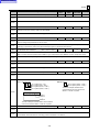
The meanings of our safety precautions to DANGER, WARNING, and CAUTION are as
follows:
: Failure to follow these instructions could result in loss of life.
DANGER
: Failure to observe these instructions could result in serious harm to a human
life or body.
WARNING
: Failure to observe these instructions could result in minor injuries or serious
machine damage.
CAUTION
HGENPA0040E
S-1
Return to Library
SAFETY PRECAUTIONS
Basics
! After turning power on, keep hands away from the keys, buttons, or switches of the
operating panel until an initial display has been made.
WARNING
! Before proceeding to the next operations, fully check that correct data has been entered
and/or set. If the operator performs operations without being aware of data errors,
unexpected operation of the machine will result.
! Before machining workpieces, perform operational tests and make sure that the machine
operates correctly. No workpieces must be machined without confirmation of normal
operation. Closely check the accuracy of programs by executing override, single-block, and
other functions or by operating the machine at no load. Also, fully utilize tool path check,
solid check, and other functions, if provided.
! Make sure that the appropriate feed rate and rotational speed are designated for the
particular machining requirements. Always understand that since the maximum usable feed
rate and rotational speed are determined by the specifications of the tool to be used, those
of the workpiece to be machined, and various other factors, actual capabilities differ from
the machine specifications listed in this manual. If an inappropriate feed rate or rotational
speed is designated, the workpiece or the tool may abruptly move out from the machine.
! Before executing correction functions, fully check that the direction and amount of
correction are correct. Unexpected operation of the machine will result if a correction
function is executed without its thorough understanding.
! Parameters are set to the optimum standard machining conditions prior to shipping of the
machine from the factory. In principle, these settings should not be modified. If it becomes
absolutely necessary to modify the settings, perform modifications only after thoroughly
understanding the functions of the corresponding parameters. Modifications usually affect
any program. Unexpected operation of the machine will result if the settings are modified
without a thorough understanding.
Remarks on the cutting conditions recommended by the NC
! Before using the following cutting conditions:
WARNING
- Cutting conditions that are the result of the MAZATROL Automatic Cutting Conditions
Determination Function
- Cutting conditions suggested by the Machining Navigation Function
- Cutting conditions for tools that are suggested to be used by the Machining Navigation
Function
Confirm that every necessary precaution in regards to safe machine setup has been taken –
especially for workpiece fixturing/clamping and tool setup.
! Confirm that the machine door is securely closed before starting machining.
Failure to confirm safe machine setup may result in serious injury or death.
S-2
Return to Library
SAFETY PRECAUTIONS
Programming
WARNING
! Fully check that the settings of the coordinate systems are correct. Even if the designated
program data is correct, errors in the system settings may cause the machine to operate in
unexpected places and the workpiece to abruptly move out from the machine in the event
of contact with the tool.
! During surface velocity hold control, as the current workpiece coordinates of the surface
velocity hold control axes approach zeroes, the spindle speed increases significantly. For
the lathe, the workpiece may even come off if the chucking force decreases. Safety speed
limits must therefore be observed when designating spindle speeds.
! Even after inch/metric system selection, the units of the programs, tool information, or
parameters that have been registered until that time are not converted. Fully check these
data units before operating the machine. If the machine is operated without checks being
performed, even existing correct programs may cause the machine to operate differently
from the way it did before.
! If a program is executed that includes the absolute data commands and relative data
commands taken in the reverse of their original meaning, totally unexpected operation of
the machine will result. Recheck the command scheme before executing programs.
! If an incorrect plane selection command is issued for a machine action such as arc
interpolation or fixed-cycle machining, the tool may collide with the workpiece or part of the
machine since the motions of the control axes assumed and those of actual ones will be
interchanged. (This precaution applies only to NC units provided with EIA functions.)
! The mirror image, if made valid, changes subsequent machine actions significantly. Use
the mirror image function only after thoroughly understanding the above. (This precaution
applies only to NC units provided with EIA functions.)
! If machine coordinate system commands or reference position returning commands are
issued with a correction function remaining made valid, correction may become invalid
temporarily. If this is not thoroughly understood, the machine may appear as if it would
operate against the expectations of the operator. Execute the above commands only after
making the corresponding correction function invalid. (This precaution applies only to NC
units provided with EIA functions.)
! The barrier function performs interference checks based on designated tool data. Enter the
tool information that matches the tools to be actually used. Otherwise, the barrier function
will not work correctly.
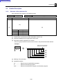
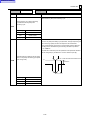
! The system of G-code and M-code commands differs, especially for turning, between the
machines of INTEGREX e-Series and the other turning machines.
Issuance of the wrong G-code or M-code command results in totally non-intended machine
operation. Thoroughly understand the system of G-code and M-code commands before
using this system.
Sample program
Machines of INTEGREX e-Series
Turning machines
S1000M3
–1
The milling spindle rotates at 1000 min .
The turning spindle rotates at 1000 min–1.
S1000M203
The turning spindle rotates at 1000 min–1.
The milling spindle rotates at 1000 min–1.
S-3
Return to Library
SAFETY PRECAUTIONS
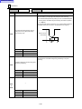
! For the machines of INTEGREX e-Series, programmed coordinates can be rotated using
an index unit of the MAZATROL program and a G68 command (coordinate rotate command) of the EIA program. However, for example, when the B-axis is rotated through 180
degrees around the Y-axis to implement machining with the turning spindle No. 2, the plus
side of the X-axis in the programmed coordinate system faces downward and if the
program is created ignoring this fact, the resulting movement of the tool to unexpected
positions may incite collisions.
To create the program with the plus side of the X-axis oriented in an upward direction, use
the mirror function of the WPC shift unit or the mirror imaging function of G-code command
(G50.1, G51.1).
! After modifying the tool data specified in the program, be sure to perform the tool path
check function, the solid check function, and other functions, and confirm that the program
operates properly. The modification of tool data may cause even a field-proven machining
program to change in operational status.
If the user operates the machine without being aware of any changes in program status,
interference with the workpiece could arise from unexpected operation.
For example, if the cutting edge of the tool during the start of automatic operation is present
inside the clearance-including blank (unmachined workpiece) specified in the common unit
of the MAZATROL program, care is required since the tool will directly move from that
position to the approach point because of no obstructions being judged to be present on
this path.
For this reason, before starting automatic operation, make sure that the cutting edge of the
tool during the start of automatic operation is present outside the clearance-including
workpiece specified in the common unit of the MAZATROL program.
CAUTION
! If axis-by-axis independent positioning is selected and simultaneously rapid feed selected
for each axis, movements to the ending point will not usually become linear. Before using
these functions, therefore, make sure that no obstructions are present on the path.
S-4
Return to Library
SAFETY PRECAUTIONS
Operations
WARNING
! Single-block, feed hold, and override functions can be made invalid using system variables
#3003 and #3004. Execution of this means the important modification that makes the
corresponding operations invalid. Before using these variables, therefore, give thorough
notification to related persons. Also, the operator must check the settings of the system
variables before starting the above operations.
! If manual intervention during automatic operation, machine locking, the mirror image
function, or other functions are executed, the workpiece coordinate systems will usually be
shifted. When making machine restart after manual intervention, machine locking, the
mirror image function, or other functions, consider the resulting amounts of shift and take
the appropriate measures. If operation is restarted without any appropriate measures being
taken, collision with the tool or workpiece may occur.
! Use the dry run function to check the machine for normal operation at no load. Since the
feed rate at this time becomes a dry run rate different from the program-designated feed
rate, the axes may move at a feed rate higher than the programmed value.
! After operation has been stopped temporarily and insertion, deletion, updating, or other
commands executed for the active program, unexpected operation of the machine may
result if that program is restarted. No such commands should, in principle, be issued for the
active program.
! During manual operation, fully check the directions and speeds of axial movement.
CAUTION
! For a machine that requires manual homing, perform manual homing operations after
turning power on. Since the software-controlled stroke limits will remain ineffective until
manual homing is completed, the machine will not stop even if it oversteps the limit area.
As a result, serious machine damage will result.
! Do not designate an incorrect pulse multiplier when performing manual pulse handle feed
operations. If the multiplier is set to 1000 times and the handle operated inadvertently, axial
movement will become faster than that expected.
S-5
Return to Library
OPERATIONAL WARRANTY FOR THE NC UNIT
OPERATIONAL WARRANTY FOR THE NC UNIT
The warranty of the manufacturer does not cover any trouble arising if the NC unit is used for its
non-intended purpose. Take notice of this when operating the unit.
Examples of the trouble arising if the NC unit is used for its non-intended purpose are listed
below.
1.
Trouble associated with and caused by the use of any commercially available software
products (including user-created ones)
2.
Trouble associated with and caused by the use of any Windows operating systems
3.
Trouble associated with and caused by the use of any commercially available computer
equipment
Operating Environment
1.
Ambient temperature
During machine operation: 0° to 50°C (0° to 122°F)
2.
Relative humidity
During machine operation: 10 to 75% (without bedewing)
Note:
As humidity increases, insulation deteriorates causing electrical component parts to
deteriorate quickly.
S-6 E
Return to Library
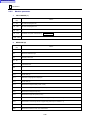
CONTENTS
Page
1
INTRODUCTION .................................................................................. 1-1
2
PARAMETER ....................................................................................... 2-1
2-1
Outline ................................................................................................................2-1
2-1-1
Types of parameters............................................................................................... 2-1
2-1-2
Precautions............................................................................................................. 2-2
2-2
Parameter List ....................................................................................................2-3
2-2-1
User parameter....................................................................................................... 2-3
2-2-2
Machine parameter............................................................................................... 2-28
2-2-3
Data I/O parameter ............................................................................................... 2-55
2-3
Detailed Description .........................................................................................2-59
2-3-1
Structure of the parameter list .............................................................................. 2-59
2-3-2
User parameter
POINT (D) ................................................................................ 2-61
2-3-3
User parameter
LINE/FACE/3D (E) ................................................................... 2-82
2-3-4
User parameter
EIA/ISO (F)............................................................................. 2-106
2-3-5
User parameter
SOFT LIMIT (I) ....................................................................... 2-152
2-3-6
User parameter
SYSTEM (SU) ........................................................................ 2-157
2-3-7
User parameter
TURNING (TC)....................................................................... 2-168
2-3-8
User parameter
SOLID (SD) ............................................................................ 2-206
2-3-9
Machine parameter
CALL MACRO (J)............................................................. 2-208
2-3-10 Machine parameter
MEASURE (K).................................................................. 2-210
2-3-11 Machine parameter
TABLE (L) ........................................................................ 2-240
2-3-12 Machine parameter
FEED VEL. (M) ................................................................ 2-275
2-3-13 Machine parameter
TIME CONST. (N) ............................................................ 2-288
C-1
Return to Library
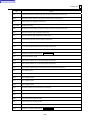
3
2-3-14 Machine parameter
ANOTHER (S) .................................................................. 2-296
2-3-15 Machine parameter
SPINDLE (SA).................................................................. 2-302
2-3-16 Machine parameter
BARRIER (BA) ................................................................. 2-319
2-3-17 Data I/O parameter
CMT parameter (CMT) ..................................................... 2-342
2-3-18 Data I/O parameter
TAPE parameter (TAP) .................................................... 2-345
2-3-19 Data I/O parameter
DNC parameter (DNC) ..................................................... 2-355
2-3-20 Data I/O parameter
OTHER (IOP/DPR/IDD).................................................... 2-365
ALARM ................................................................................................. 3-1
3-1
Outline ................................................................................................................3-2
3-1-1
Alarm display .......................................................................................................... 3-2
3-1-2
Precautions............................................................................................................. 3-3
3-2
Detailed Description ...........................................................................................3-4
3-2-1
Structure of the alarm list........................................................................................ 3-4
3-2-2
No. 1 - No. 99, No. 1000 - No. 1099 (System/Drive error)...................................... 3-5
3-2-3
No. 100 - No. 199, No. 1100 - No. 1199 (CNC machine control error) ................. 3-12
3-2-4
No. 200 - No. 399, No. 1200 - No. 1399 (PLC machine control error).................. 3-22
3-2-5
No. 400 - No. 499, No. 1400 - No. 1499 (CNC screen operation error)................ 3-23
3-2-6
No. 500 - No. 599, No. 1500 - No. 1599 (I/O error) .............................................. 3-40
3-2-7
No. 600 - No. 699, No. 1600 - No. 1699 (MAZATROL program error) ................. 3-52
3-2-8
No. 700 - No. 799, No. 1700 - No. 1799 (MAZATROL program error) ................. 3-64
3-2-9
No. 800 - No. 899, No. 1800 - No. 1899 (EIA/ISO program error)........................ 3-76
3-2-10 No. 900 - No. 999, No. 1900 - No. 1999 (EIA/ISO program error)........................ 3-89
3-2-11 No. 2100 - No. 2199 (Interference error) ............................................................ 3-101
4
M-CODE LIST....................................................................................... 4-1
C-2 E
Return to Library
INTRODUCTION
1
1
INTRODUCTION
This manual describes the meaning and setting of various parameters, and the meaning and
elimination procedure of various alarms used for the MAZATROL MATRIX System. This
document also gives the list of M-codes.
For detailed description of the MAZATROL MATRIX System, refer to the Operating Manual of
the machine.
Read this manual and the Operating Manual of the machine carefully in order to make the best
use of the possibilities of the MAZATROL MATRIX System.
1-1
Return to Library
1
INTRODUCTION
- NOTE -
1-2 E
Return to Library
PARAMETER
2
2-1
2
PARAMETER
Outline
1.
Scope of this chapter
This chapter describes the parameters you can change as required. How to read the list is
described in the beginning. Always refer to this list to change parameters.
2.
Precautions on this chapter
This chapter also gives parameters relating to optional functions. Accordingly, the list
includes parameters which cannot be changed. Check the type of machine purchased by
you and its specifications before you read the list.
Note 1: The contents of this list are subjected to change without notice, for NC unit or machine
improvement.
Note 2: Any questions about the contents of this list should be communicated to Mazak
Technical Center or Technology Center.
2-1-1
Types of parameters
Parameters, which refer to constants specific to the NC machines and equipment and the data
necessary for cutting operations, possess a very important meaning.
Parameters can be broadly divided into the following three types according to their meaning.
- User parameters
The data required for processes such as point machining, line machining, plane machining,
turning, and EIA/ISO programmed machining, is registered. The USER PARAMETER display
is used to register the user parameters.
- Machine parameters
Constants related to the servomotors and spindle motors, machine status data etc. are
registered. The MACHINE PARAMETER display is used to register the machine parameters.
- Data I/O parameters
The data required for connection to external units such as a CMT unit and a tape unit, is
registered. The DATA I/O PARAMETER display which can be selected on the DATA I/O
display is used to register the data I/O parameters.
2-1
Return to Library
2
PARAMETER
2-1-2
Precautions
1.
Details of the parameters may differ according to the machine used, the presence/absence
of an option(s), the production time of the NC machines and equipment, etc. Therefore, do
not use the parameters of other machines.
2.
The parameter list is supplied in the form of data sheets within the NC electronic cabinet at
shipment of the machines. Be careful not to lose the list.
3.
Before making changes to details of a parameter, make sure that the parameter is the one
to be changed.
4.
If details of the parameter to be changed cannot be clearly understood, contact Mazak
Technical Center or Technology Center.
5.
When changing details of a parameter, maintain records of the old and new data.
6.
If the particular machine is not used for a long time, then the battery to protect the parameter
memory will run down. (Battery alarm)
In that case, errors will occur in the parameters and thus machine malfunctions may result.
To prevent this, first check the existing details of the parameters closely against the
separate parameter list and then make the necessary changes to the parameters.
7.
In addition to the parameters listed in this document, those related to PLC (Programmable
Logic Controller) are also available; refer to the OPERATING MANUAL of the machine for
details of the PLC-related parameters and the PLC Parameter List in the ELECTRIC
WIRING DIAGRAM.
2-2
Return to Library
PARAMETER
2-2
2
Parameter List
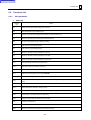
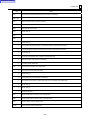
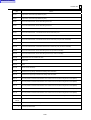
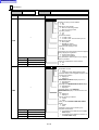
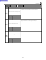
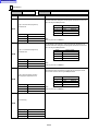
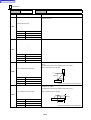
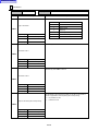
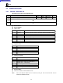
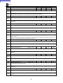
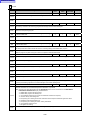
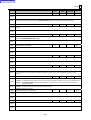
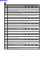
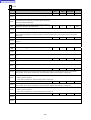
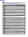
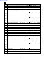
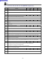
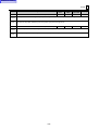
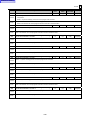
2-2-1
User parameter
1.
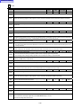
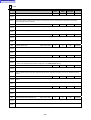
POINT (D)
Address
(bit)
Outline
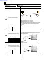
D1
Height of the second R-point during point machining
D2
Nominal diameter of spot-machining tool
D3
Number of revolutions during dwell at hole bottom in spot-machining cycle
D4
Maximum allowable spot-chamfering hole diameter element
D5
Prehole through speed during inversed spot-facing
D6
Drill-machining cycle setting element
D7
Drill-machining cycle setting element
D8
Maximum diameter of holes machinable on one drill
D9
Maximum diameter of holes machinable on two drills
D10
Maximum diameter of holes machinable on three drills
D11
Through-hole/tap-prehole machining overshoot
D12
Stop-hole machining hole-bottom clearance
D13
Spot-machining hole diameter (fixed value)
D14
Depth-of-cut setting element for drilling (ALMINUM)
D15
Depth-of-cut setting element for drilling (except AL)
D16
Number of revolutions during dwell at hole bottom for chamfering cutter or spot-machining tool in chamfering
cycle
D17
Interference clearance of chamfering cutter
D18
Return feed rate for reaming or boring (cycle 3)
D19
Number of revolutions during dwell at hole bottom for end milling
D20
Radial depth-of-cut setting element for end milling
D21
Reference bottom-finishing allowance for end milling
D22
Tapping-cycle dwell time
D23
Prehole clearance for end milling
D24
Number of revolutions during dwell at hole bottom for boring
2-3
Return to Library
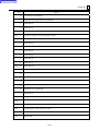
2
PARAMETER
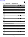
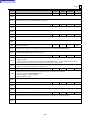
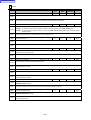
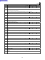
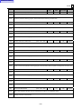
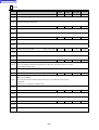
Address
(bit)
Outline
D25
Boring-bar tip relief
D26
Returning distance from hole bottom for boring or back-boring
D27
—
D28
Bottom-finishing amount of boring
D29
Chip removal time
D30
Number of incomplete threads in tapping cycle
D31
Tapper elongation amount for tapping
D32
Number of spindle revolutions until spindle CCW rotation begins in tapping cycle
D33
Back-boring tool tip relief
D34
—
D35
Prehole-drilling diameter setting element for reamer (drilling)
D36
Prehole-drilling diameter setting element for reamer (boring)
D37
Prehole-drilling diameter setting element for reamer (end milling)
D38
Reamer-prehole diameter setting element for boring or end milling
D39
Reamer-prehole diameter setting element for end milling
D40
Number of revolutions during dwell at spot-faced hole bottom for inversed spot-facing
D41
R-point height during point-machining
D42
Height of the third R-point during point machining
D43
Number of incomplete threads in tapping cycle for piped screw
D44
—
D45
Gradual decrements in drilling depth
D46
Minimum gradual drilling depth
D47
Reamer-prehole machining overshoot
D48
Feed override for the section to be chamfered in the planetary tapping cycle
D49
Amount of return at hole bottom during the planetary tapping cycle
D50
Auto-set feed rate for pre-hole machining in the planetary tapping cycle
D51
Auto-set feed rate for planetary tapping cycle
2-4
Return to Library
PARAMETER
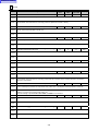
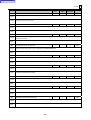
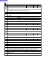
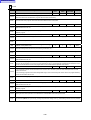
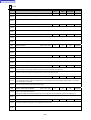
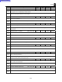
Address
(bit)
2
Outline
D52
Reduction ratio for the G00-based relief rate during a very-deep-hole drilling cycle
D53
Number of times of pecking up to the return of the tool to a position near the starting point of the very-deephole drilling cycle of a drilling or turning-drilling unit
D54
Deceleration rate at cutting start for very-deep-hole drilling cycle/decremental very-deep-hole machining cycle
D55
Drilling return distance for very-deep-hole drilling cycle/decremental very-deep-hole machining cycle
D56
Number of revolutions during dwell at chip ejection position and hole bottom for very-deep-hole drilling
cycle/decremental very-deep-hole machining cycle
D57
Return speed for very-deep-hole drilling cycle/decremental very-deep-hole machining cycle
D58
Feed rate reduction distance ratio at cutting start of a very-deep-hole drilling cycle/decremental very-deephole machining cycle
D59
Circumferential speed reduction ratio at cutting end of a very-deep-hole drilling cycle/decremental very-deephole machining cycle
D60
Automatic setting ratio of axial cutting feed rate during chamfering
D61 - D72
—
D73 - D77
Learning of cutting conditions (DEP-Z range)
D78 - D82
Learning of cutting conditions (WID-R range)
D83 - D90
—
D91
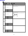
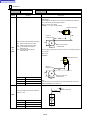
0
M04 is output/not output after the tool has dwelled at the hole bottom during a tapping cycle.
1
The tool dwells/does not dwell after M04 has been output at the hole bottom during a tapping cycle.
2
The tool dwells/does not dwell after it has been returned to the R-point during a tapping cycle.
3
If a drill is used in the pre-machining of the centering drill cycle, the R-point height is set to D1 or not.
4
The finishing tool path is shortened/not shortened during a true-circle processing cycle (end milling).
5
The tool path is shortened/not shortened during a true-circle processing cycle (chamfering).
6
If a pre-machining tool sequence is included in the same unit, the R-point height of the drill is set/not set to D1
or D42.
7
The R-point height of the chamfering cutter during the cycle 2 is set to D42 or not.
The R-point height of the spot-machining tool during the chamfering cycle (cycle 2) is set to D42 or not.
0
During a true-circle processing (end milling) cycle, E17 is used for axial feed or not.
1
The R1-point height of the back spot facing is set to D1 or not.
2
If a chamfering cutter is included in the premachining tool sequence of the same unit, the R-point height of the
reamer is set to D1 or not.
3
If a chamfering cutter is included in the pre-machining tool sequence of the same unit, the R-point height of
the tapping is set to D1 or not.
4
—
5
—
D92
2-5
Return to Library
2
PARAMETER
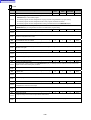
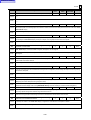
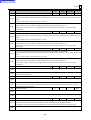
Address
(bit)
Outline
6
During planetary tapping, chips are ejected/not ejected automatically prior to the threading process.
7
—
D93
Unidirectional positioning for point-machining
D94
Unidirectional positioning for point-machining
D95
Auto-setting method for tapping
D96 - D144
—
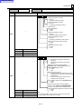
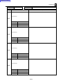
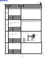
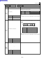
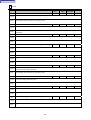
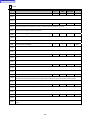
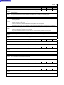
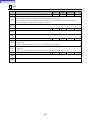
2.
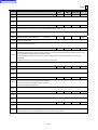
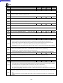
LINE/FACE/3D (E)
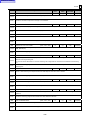
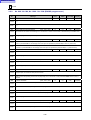
Address
(bit)
Outline
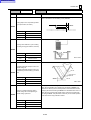
E1
Closed-pattern cutting start point and escape point setting element
E2
Cutting start point and escape point setting element (the first clearance)
E3
—
E4
Reference allowance of finishing in radial direction
E5
Element used to set the cutting start point and escape point (the second clearance)
E6
Reference allowance of finishing in axial direction
E7
Allowance of cutting start point in axial direction (the second clearance)
E8
Radial interference clearance of chamfering cutter
E9
Allowance of axial-cutting start position (the first clearance)
E10
Depth-of-cut-R automatic setting element (Face milling, End milling-top, End milling-step)
E11
Axial interference clearance of chamfering cutter
E12
Radial interference clearance of face milling unit and angular face milling unit
E13
Tool path setting element for end milling-top unit
E14
Depth-of-cut-R automatic setting element (Pocket milling, Pocket milling-mountain, Pocket milling-valley)
E15
Tool path setting element for face milling-top unit (reciprocating short)
E16
Peripheral-cutting feed rate override for end milling-mountain unit
E17
Axial-cutting feed rate override
E18
Override in case of the overall width cutting for pocket-machining
E19
Returning feed rate override in case of bidirectional cutting for rough-machining of the end milling-slot unit.
2-6
Return to Library
PARAMETER
Address
(bit)
2
Outline
E20
Axial cutting feed override during Z-axial cutting in the pecking mode of face machining
E21
Wall-cutting overlap in closed figure
E22
Override value of automatic corner over-riding
E23
Effective removal allowance (upper limit) of automatic corner overriding
E24
Effective removal allowance (lower limit) of automatic corner overriding
E25
Effective angle (upper limit) of automatic corner overriding
E26
Calculation coefficient for the finishing feed of line milling
E27
Radial direction feed rate calculation reference diameter for finish cutting in line machining unit
E28
Finishing feed rate calculation reference feed rate in line machining unit
E29
Selection of whether the cutting conditions in the shape sequence during VFC mode are to be modified
E30
An element that determines the starting point and escape point of radial cutting when CLOSED is specified
for the wall attributes at the starting point and ending point of open-pattern line machining
E31
Element that determines the amount of OPEN attribute wall protrusion in pocket-machining shape units
E32
Element that automatically determines an approaching radius in a Z-direction helical approach scheme
E33
Approaching gradient during a helical approach scheme
E34
Element that automatically determines an approaching distance in a Z-direction tapered approach scheme
E35
Approaching gradient during the tapered approach scheme
E36
Element that automatically determines an escape distance in the Z-direction tapered escape scheme
E37
The amount of return of pecking in the Z-axial pecking mode of face machining
E38
The returning feed rate of pecking in the Z-axial pecking mode of face machining
E39 - E54
—
E55
3-D, Axial cutting-feed overriding
E56
3-D, Inversion check of curved-surface pattern
E57
3-D, Severity check of cutting pitch
E58
3-D, Tool-diameter compensation
E59
3-D, Allowance of axial-cutting start position
E60
3-D, Normal cutting allowance
E61
3-D, Search length for parallel cutting
2-7
Return to Library
2
PARAMETER
Address
(bit)
Outline
E62
3-D, Search length for right-angle cutting
E63
3-D, Pattern display division segment (FL direction)
E64
3-D, Pattern display division segment (GL direction)
E65
3-D, Radial cutting allowance for area check
E66
3-D, Axial cutting allowance for area check
E67 - E75
3-D, Processing error tolerance
E76
3-D, Entire-width override
E77
3-D, Radial cutting allowance for high-speed rough processing (workpiece size appointment)
E78
3-D, Multiplying factor set for tolerance
E79 - E82
—
E83
3-D, Region of radial machining during high-speed rough processing (offset appointment)
E84
3-D, Region of axial machining during high-speed rough processing (offset appointment)
E85
3-D, Region of radial machining during high-speed rough processing: –X (workpiece size appointment)
E86
3-D, Region of radial machining during high-speed rough processing: +X (workpiece size appointment)
E87
3-D, Region of radial machining during high-speed rough processing: –Y (workpiece size appointment)
E88
3-D, Region of radial machining during high-speed rough processing: +Y (workpiece size appointment)
E89
3-D, Region of axial machining during high-speed rough processing (workpiece size appointment)
E90
—
E91
Tool-path pattern selection for end milling-mountain unit
E92
Tool-path pattern selection for pocket milling unit
E93
Tool-path pattern selection for pocket milling-mountain unit
E94
Tool-path pattern selection for pocket milling-valley unit
E95
Tool-path pattern selection for line-machining unit
E96
Tool-path pattern selection for end milling-slot unit
E97
Tool-path pattern selection for end milling-top unit
E98
Cutting method selection for end milling-mountain, pocket milling-valley unit
E99
Milling feed rate specification range for the shape sequence of the MAZATROL program
2-8
Return to Library
PARAMETER
Address
(bit)
Outline
E100 - E103
—
E104
Tool path selection
E105 - E144
—
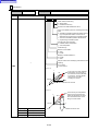
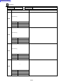
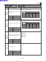
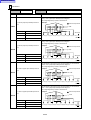
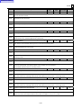
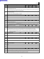
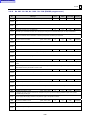
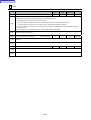
3.
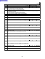
EIA/ISO (F)
Address
(bit)
Outline
F1
G61.1 corner deceleration coefficient (%)
F2
G61.1 arc-clamping speed coefficient (%)
F3
For high-speed smoothing control
F4
Fixed value (0)
F5
Fixed value (0)
F6
Minimum allowable height of stepped sections for deceleration in high-speed smoothing control mode
F7
Fixed value (0)
F8
Corner deceleration speed coefficient for high-speed smoothing control
F9
Circler cutting clamp speed coefficient for high-speed smoothing control
F10
—
F11
Vector constant for 3-D, tool-diameter compensation
F12
Return amount of pecking in drill high-speed deep-hole cycle or in G73
F13
Allowance amount of rapid-feed stop in deep-hole drilling cycle or in G83
F14
Rotation center of coordinates (axis of abscissa)
F15
Rotation center of coordinates (axis of ordinate)
F16
Horizontal length of coordinate rotation
F17
Vertical length of coordinate rotation
F18
Angle of coordinate rotation
F19
Maximum permissible difference in arc radius
F20
Fixed value of scaling factor
F21
Maximum inside-corner angle available with automatic corner override (G62)
2-9
2
Return to Library
2
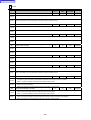
PARAMETER
Address
(bit)
Outline
F22
Deceleration area of automatic corner overriding (G62)
F23 - F26
—
F27
Handling of G92 (spindel speed clamp value) command at restart
F28
Threading chamfering angle
F29
Override value of automatic corner overriding (G62)
F30
G-code type selection
F31 - F39
—
F40
Operating method selection in tape mode
F41
Threading termination waiting time processing
F42
Deceleration area r during Z-axis measurement
F43
Measurement area d during Z-axis measurement
F44
Measuring speed f
F45
—
F46
—
F47 - F66
Common variable name
F67
—
F68
—
F69
EIA/ISO program restart method
F70
Availability of multiple-machining and designated number of repetitions in the EIA/ISO subprogram
F71
Machining order control
F72
Selection of the shape correction function of the MAZATROL program
F73
M-code execution time for time study
F74
S-code execution time for time study
F75
T-code execution time for time study
F76
B-code execution time for time study
F77
Basis rate for tool life judgment
F78
Selection of separating ratio of graphic display
2-10
Return to Library
PARAMETER
Address
(bit)
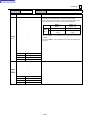
F79
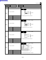
F80
F82
F83
Outline
0
Holding of memory monitor address valid/invalid
1
Selection of menu display
2
Key history function valid/invalid
3
Tool search method
4
Selection of tap gear
5
Display of tools currently in use valid/invalid
6
Initial value of synchronous/asynchronous tapping during tapping tool registration
7
Display of a MAZATROL monitor window valid/invalid
0
MAZATROL function valid/invalid
1
Automatic display of the navigation window on the occurrence of an alarm valid/invalid
2
MAINTENANCE CHECK display at power on, displayed/not displayed
3
Third page of the MAINTENANCE CHECK display, displayed/not displayed
4
GRAPHIC MAINTENANCE display on the occurrence of an alarm, displayed/not displayed
5
Learning of cutting conditions valid/invalid
6
Editing on the CUTTING CONDITION LEARN display valid/invalid
7
Destination of spare tool correction by the workpiece measurement
F81
2
Program management function
0
Characteristics estimation result graph, displayed/not displayed
1
Selection of inch/metric representation in POSITION display, TOOL DATA display, and TOOL OFFSET
display modes valid/invalid
2
Basis for tool life judgment
3
—
4
X-axis diameter display on the POSITION display valid/invalid
5
Whether the stored tools registration function on the VISUAL TOOL MANAGEMENT display is to be made
valid or invalid when the visual tool ID/data management functions are valid
6
—
7
—
0
Output of the alarm history data as text data valid/invalid
1
Operation record function valid/invalid
2-11
Return to Library
2
PARAMETER
Address
(bit)
F84
F85
F86
Outline
2
—
3
—
4
Program conversion type selection 1
5
Program conversion type selection 2
6
CMT/DNC input conversion type selection (only for lathe)
7
—
0
Fixed value (1)
1
Fixed cycle (B → J)
2
Spare tool search for EIA
3
Timing to validate new workpiece offset data specified with a system variable
4
Machine coordinate system (G92) selection
5
Incremental/absolute data command in high-speed machining mode
6
Tape operation, Not operated until the buffer is full/Operated at a unit of EOB
7
When no tool data has been designated during EIA/ISO program execution with the MAZATROL tool length
data validated, operation is executed/ alarm state
0
Table rotational machining
1
Radial interference check
2
Type of coordinate system for controlling the tool tip point
3
Tool tip point control scheme
4
Fixed value (0)
5
Reset to cancel G68.2, valid/invalid
6
Display of surface definition θ
7
Output of the B-axis unclamping code before B-axis indexing, valid/invalid
0
Output of M250 (Spindle Speed Confirmation) before a turning feed, valid/invalid
1
Milling-spindle start timing for a milling unit (with MILL&TURN. set under TYPE of UNo. 0)
2
Override scheme for G0 during tool tip point control
3
—
4
Display of the PART SHAPE window
2-12
Return to Library
PARAMETER
Address
(bit)
F87
Outline
5
Override scheme for G1 during tool tip point control
6
Selection of rotary axis reference position for tool tip point control
7
Display format of REMAIN on the POSITION display
0
Selection of whether or not the tool is to be offset by each change only in the deviation vector
1
Selection of whether or not the check for mismatch of the workpiece origin and table rotation center is to be
conducted
2
Data alteration checking function valid/invalid
3
—
4
—
5
—
6
—
7
—
F88
Set this parameter to specify functions related to the conversion from MAZATROL program into an EIA
program.
F89
Set this parameter to specify functions related to the conversion from MAZATROL program into an EIA
program.
F90
—
F91
F92
2
0
In response to move command without decimal point, tool moves by 1/tool moves by 10
1
Coordinate system shift using a MAZATROL program, valid/invalid
2
Stroke inside check before movement/Stroke outside check before movement
3
—
4
Metric (Initial G20 is valid/invalid)/Inch
5
In response to move command without decimal point:
6
G00 interpolation/non-interpolation
7
G33E command is for the number of threads per inch/command is for thread cutting with precise lead
0
Modal at power-on or at reset (G17 or G19/G18)
1
Modal at power-on or at reset (G17 or G19/G18)
2
Fixed value (0), Dwell command always in time
3
Tool-length compensation (G43 or G44) axis
4
Tool-diameter compensation (G41 or G42) start up/cancel type
2-13
Return to Library
2
PARAMETER
Address
(bit)
F93
F94
F95
Outline
5
Tool-diameter compensation (G41 or G42) interference check
6
Fixed-cycle hole-drilling axis
7
Tool diameter compensation for an EIA/ISO program
0
—
1
Modal at power-on or at reset (G94/G95)
2
Modal at power-on or at reset (G91/G90)
3
Tool length of tool data for EIA/ISO program, valid/invalid
4
Feed rate during machine lock
5
Middle point during reference-point return
6
Single-block operation mode at user macro operation instruction
7
Fixed value (0)
0
Movement to hole-drilling position in fixed-cycle mode
1
External deceleration signal valid/invalid
2
Tool length offsetting during G28/G30 execution, canceled/performed
3
Modal at power-on or at reset (G01/G00)
4
Tool command method using T-codes
5
Fixed value (0)
6
Fixed value (1)
7
Tool offset amount effectuated in an EIA/ISO program
0
Interrupt function using user macro instruction, valid/invalid
1
Handling of macroprogram interruption and call
2
Automatic return position to restart the program (Fixed to 1)
3
G00 (positioning) command feed rate for dry run
4
—
5
—
6
Manual-pulse interrupt amount cancellation with reset key, valid/invalid
7
Coordinate system corresponding to G54 set with reset key, valid/invalid
2-14
Return to Library
PARAMETER
Address
(bit)
F96
Outline
0
Selection of variable number for tool offset amount
1
Fairing function valid/invalid
2
Processing for arc command blocks in high-speed machining mode, nonuniform feed/uniform feed
3
—
4
Selection of a corner judgment criterion in high-speed machining mode
5
Selection of a cutting feed clamping speed in high-speed machining mode
6
Rotational axis shape correction valid/invalid
7
—
F97
Selection of G-code of the coordinates system to be used in the EIA conversion function
F98
Number of macro variable to be used in the EIA conversion function
F99
Offset amount for the subprogram WNo. to the main WNo. concerned in case of output with subprogram in
the EIA conversion function
F100
Spline cancel length
F101
Spline cancel angle
F102
Fine spline interpolation curve error (Block including the point of inflection)
F103
Spline interpolation fairing block length
F104
Fine spline interpolation curve error (Block including no inflection point)
F105
—
F106
—
F107
Small block judgment length
F108
Corner deceleration angle increment value
F109
—
F110
—
F111
0
Selection of display type of tapping tool in solid mode
1
Use/disuse of dry run during thread cutting
2
Use/disuse of feed hold during thread cutting
3
Direction of rotation of the C-axis during C-axial threading with G01.1
4
EIA tool command suffix valid/invalid
2-15
2
Return to Library
2
PARAMETER
Address
(bit)
5
Tool correction amount selection for EIA/ISO programs
6
Execution mode selection for a fixed turning cycle
7
Form of single-block stop during a fixed turning cycle
F112
F113
F114
Outline
Selection of measurement data items to be printed out
0
Counting all types of use under the same tool number for the tool life management on the TOOL DATA
display executed/not executed
1
Data handling on the milling tool of a group that has expired in tool life
2
Data handling on the turning tool of a group that has expired in tool life
3
Tool life management of the FLASH tool
4
Tool life management — Life time
5
Tool life management — Maximum available wear offset data X
6
Tool life management — Maximum available wear offset data Y
7
Tool life management — Maximum available wear offset data Z
0
Selection of the maximum C-axial cutting feed rate for the inch system
1
Selection of the operation occurring during the control of the tool tip point when command G49 is issued
(when the tool length offset value is canceled)
2
Tool shape check during tool measurement, valid/invalid
3
Moving axes by using G49 (tool length cancel) in G43 (tool length offset) mode, valid/invalid
4
Selecting a rethreading function
5
Output timing of a tool life alarm
6
Initial setting of G53.5
7
The life of the tool is judged/not judged from its machining count
F115
Restart/TPS approach speed
F116
Feed rate of the threading runout — X-axis
F117
Feed rate of the threading runout — Y-axis
F118
Feed rate of the threading runout — Z-axis
F119
Runout feed rate for the inside diameter threading cycle
F120
Clamping speed for the threading cycle — X-axis
F121
Clamping speed for the threading cycle — Y-axis
2-16
Return to Library
PARAMETER
Address
(bit)
2
Outline
F122
Clamping speed for the threading cycle — Z-axis
F123
—
F124
Permissible data alteration amount 1 for input error prevention function
F125
Permissible data alteration amount 2 for input error prevention function
F126 - F132
—
F133
Pitch of tapping tool for display in detail in solid mode
F134
Thread depth of tapping tool for display in detail in solid mode
F135
Tool-drawing accuracy in solid mode
F136
Amount of offset for dummy workpiece shape in solid mode
F137
Number of jaws displayed in solid mode for No. 1 turning spindle
F138
Number of jaws displayed in solid mode for No. 2 turning spindle
F139
Angle offset for the jaws displayed in solid mode for the No. 1 turning spindle
F140
Angle offset for the jaws displayed in solid mode for the No. 2 turning spindle
F141 - F144
—
F145
Rapid feed override when data alteration is detected
F146 - F153
—
F154
Parameter for system internal setting
F155 - F160
—
F161
0
Shape/wear offset number separation, valid/invalid
1
Shape offset handling
2
Tool offset timing
3
Tool offset vector handling if reset function is executed
4
Shape offset handling if offset number 0 is entered
5
Simplified wear offset, valid/invalid
6
Succession of Z/C-offsets when a MAZATROL program is called from an EIA program
7
Succession of Z/C-offsets when an EIA program is called from a MAZATROL program
0
Movement/No movement according to the particular amount of offset during independent start of tool tip point
control
F162
Setting prohibited
2-17
Return to Library
2
PARAMETER
Address
(bit)
F163
1
Type of passage of tool tip point through singular point
2
Chamfer/corner R-command address selection
3
Fixed hole-machining cycle return selection
4
6 digits in T-command for turning
5
Use of the M Pro scheme as the method of selecting the Length correction axis bit
6
MAZATROL program check for missing Z-offset, valid/invalid
7
Encoder polarity selection
0
Bar feeder scheduling function, valid/invalid
1
Incorporation of wear offset data into the current position display in EIA/ISO program mode, valid/invalid
2
Incorporation of wear offset data into the current position display in MAZATROL program mode, valid/invalid
3
Position of thread turning tool nose on solid drawing
4
Barrier check on solid drawing, valid/invalid
5
Menu on the DATA I/O display (floppy disk), displayed/hidden
6
Menu on the DATA I/O display (tape), displayed/hidden
7
Menu on the DATA I/O display (CMT), displayed/hidden
F164
F165
F166
Outline
Automatic tool data setting conditions
0
High-speed synchronous tapping function, valid/invalid
1
X-axis movement to minus side during polar coordinate interpolation, enabled/disabled
2
—
3
C-axis indexing when EIA subprogram is called from MAZATROL program
4
Modal or non-modal state of Q command in deep hole drilling cycle
5
Conversion of tool set data for milling tool based on head swivel angle when G53.5 is commanded
6
Behavior of automatic operation of an EIA program when Z-offset is not set
7
Setting at CONTI. of the END unit during tool path check, valid/invalid
0
Alteration of tool set value (tool length) on the TOOL DATA display in the automatic operation mode,
enabled/disabled
1
Type of wear offset indicated in the milling tool list on the TOOL DATA display
2
ID No./Tool name selection on the TOOL DATA display
3
—
4
—
2-18
Return to Library
PARAMETER
Address
(bit)
Outline
5
—
6
—
7
—
F167
—
F168
—
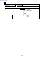
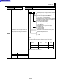
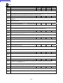
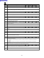
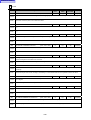
4.
SOFT LIMIT (I)
Address
(bit)
Outline
I1
Shift amount of unidirectional positioning (G60)
I2
Upper (plus direction) user soft-limit
I3
Lower (minus direction) user soft-limit
I4
—
I5
Function for making the G0 speed variable, Variable override: Minimum value
I6
—
I7
Function for making the G0 speed variable, Variable control area
I8
—
I9
Function for making the G0 speed variable, Variable control area lower limit
I10
Function for making the G0 speed variable, Variable control area upper limit
I11
Rotary center of a workpiece
I12
Clamping value for the amount of handle interruption
I13
0
Execution of G28 (reference-point return)
1
Manual zero-point return operation
2
—
3
—
4
—
5
—
6
Removal of control axes, valid/invalid
7
—
2-19
2
Return to Library
2
PARAMETER
Address
(bit)
I14
0
Mirror image with respect to the machine zero point, valid/invalid
1
—
2
User software limits (I2, I3) valid/invalid
3
Tool-tip relief after spindle orientation during execution of G75, G76, G86 or point-machining (boring or backboring), valid/invalid
4
Direction of tool-tip relief after spindle orientation during execution of G75, G76, G86 or point-machining
(boring or back-boring)
5
—
6
—
7
—
I15 - I24
5.
Outline
—
SYSTEM (SU)
Address
(bit)
Outline
SU1
Reference axis of abscissa for plane selection
SU2
Axis 1 parallel to the axis of abscissa for plane selection
SU3
Axis 2 parallel to the axis of abscissa for plane selection
SU4
Reference axis of ordinate for plane selection
SU5
Axis 1 parallel to the axis of ordinate for plane selection
SU6
Axis 2 parallel to the axis of ordinate for plane selection
SU7
Reference height axis for plane selection
SU8
Axis 1 parallel to the height axis for plane selection
SU9
Axis 2 parallel to the height axis for plane selection
SU10
Selection of tool change position specification code
SU11
Movement of axes during approach
SU12
Rotating position specified in the index unit after tool change
SU13
Axis name of the transfer axis
SU14
Tool nose mark display color on the TOOL PATH CHECK display/TRACE display
SU15
Name of thrust axis for W-axis
2-20
Return to Library
PARAMETER
Address
(bit)
2
Outline
SU16
Movement to C-axis index swivel position when Z-offset scheme is used
SU17 - SU48
—
SU49
Delay timer for the parts catcher
SU50
Tool turning clearance (radial value) in X-axis
SU51
Tool turning clearance in Z-axis
SU52
Lower-turret retraction function - Tool number of the retraction tool 1
SU53
Lower-turret retraction function - Tool number of the retraction tool 2
SU54 - SU96
—
SU97 SU100
Lower-turret retraction function - Fixed point of the retraction position
SU101
Return distance (radial value) in X-axis at wall during rough cutting in bar machining or in corner machining of
EIA/ISO program
SU102
Return distance in Z-axis at wall during rough cutting in bar machining or in corner machining of EIA/ISO
program
SU103
Cutting depth in the composite-type fixed cycle
SU104
Pecking return distance in groove cutting unit and grooving
Cut depth (diametral value) for final cut in thread cutting unit
SU105
Cut depth (diametral value) for final cut in composite-type thread cutting cycle G276, G76
SU106
Minimum cut depth clamping value in thread cutting unit and composite-type thread cutting cycle
SU107 SU152
—
SU153
0
M-code selection for tapping cycle
1
—
2
—
3
—
4
—
5
—
6
—
7
—
SU154 SU168
—
2-21
Return to Library
2
PARAMETER
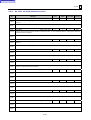
6.
TURNING (TC)
Address
(bit)
Outline
TC1
Cut depth reduction rate for rough cutting in bar machining unit, corner machining unit, and copy machining
unit
TC2
Acceleration rate in up-going taper for rough cutting in bar machining unit
TC3
Acceleration rate in up-going wall slope (90°) for rough cutting in bar machining unit
TC4
Selection of escape pattern from wall (90°) in rough cutting cycle
TC5
Deceleration rate in down-going taper for rough cutting in bar machining unit
TC6
Deceleration rate in down-going wall slope (90°) for rough cutting in bar machining unit
TC7
Acceleration rate on outside stock contour for rough cutting in copy machining unit
TC8
Acceleration pitch error ratio in thread cutting unit
TC9
Rough cutting residue ratio in cutting off cycle in groove cutting unit
TC10
Cut depth allowable incremental rate for rough cutting in groove cutting unit, edge machining unit and copy
machining unit
TC11
Deceleration rate at cutting start in turning-drilling unit
TC12
Deceleration rate at cutting end in turning-drilling unit
TC13
Deceleration rate at rough cutting start in bar machining unit and copy machining unit
TC14
Maximum permissible rate of increase of the initial cutting depth during roughing
TC15
Deceleration clearance at start of rough cutting in bar machining unit and copy machining unit
TC16
Tolerance for escape in high speed rough cutting cycle of bar machining unit
TC17
Pitch error correction during threading acceleration
TC18
Fixed value (0)
TC19
Turning-drilling cut depth calculation coefficient
TC20
Reamer return speed calculation coefficient in the turning-drilling unit
TC21
Incomplete threading portion length calculation coefficient for turning-tap tip
TC22
Turning-tapper elongation calculation coefficient
TC23
Thread height calculation coefficient for outside diameter, face/rear thread cutting (metric)
TC24
Thread height calculation coefficient for inside diameter thread cutting (metric)
TC25
Thread height calculation coefficient for outside diameter, face/rear thread cutting (inch)
TC26
Thread height calculation coefficient for inside diameter thread cutting (inch)
2-22
Return to Library
PARAMETER
Address
(bit)
2
Outline
TC27
Recessing width for #1 to #3
TC28
Recessing depth #1 to #3
TC29
Recessing width for #4
TC30
Recessing depth for #4
TC31
Recessing width for #5
TC32
Recessing depth for #5
TC33
Recessing width for #6
TC34
Recessing depth for #6
TC35
—
TC36
—
TC37
Safety contour clearance — Outside diameter clearance (radial value)
TC38
Safety contour clearance — Inside diameter clearance (radial value)
TC39
Safety contour clearance — Front clearance
TC40
Safety contour clearance — Back clearance
TC41
Thread cutting clearance (radial value)
TC42
Groove cutting clearance (radial value) in X-axis
TC43
Groove cutting clearance in Z-axis
TC44
Workpiece transfer clearance
TC45
Amount of edge clearance after roughing in the edge-machining unit
TC46
Drilling depth decrement in turning-drilling unit
TC47
Pecking return distance in turning-drilling unit
TC48
Drilling cut depth clamp value in turning-drilling unit
TC49
Spindle speed clamp value in cutting off cycle (GRV)
TC50
Number of times that the feed rate is to be reduced during the #4 and #5 cutting-off cycles of a grooving unit
TC51
Dwell at the hole bottom during non-through hole drilling cycle of the turning-drilling unit
TC52
Dwell (specification of spindle rotation number) at groove bottom in groove cutting unit
TC53
Feed rate for escape by short distance
2-23
Return to Library
2
PARAMETER
Address
(bit)
Outline
TC54
Cut depth per cycle for machining inside diameter in bar machining unit
TC55
Reverse feed tolerance for contour machining
TC56
Overtravelling in X-axis direction in edge machining unit
TC57
Workpiece pressing speed in workpiece transfer unit
TC58
Spindle speed (min–1) of two spindles in workpiece transfer while the spindles are rotating in workpiece
transfer unit
TC59
Workpiece pressing distance in workpiece transfer unit
TC60
—
TC61
Simultaneous operation pattern for transfer
TC62
Selection of tool change position specification code for FLASH tool
TC63
Amount of relief after transfer using the TRANSFER unit (Spindle mode 0 to 5)
TC64
Amount of relief after transfer using the TRANSFER unit (Spindle mode 6 and 7)
TC65
Specification of first M-code for parts catcher control
TC66
Minimum index angle of the FLASH tool
TC67
Return distance (radial value) in X-axis at wall during rough cutting in bar cutting unit or in corner machining
unit
TC68
Return distance in Z-axis at wall during rough cutting in bar cutting unit or in corner machining unit
TC69
Number of revolutions during dwell for pecking of grooving
TC70
FLASH tool — Number of cutting edges to be used for the tool not registered in the tool file
TC71
Feed stopping rotation dwell time during the chip cutting cycle
TC72
Number of times of roughing in the composite-type fixed cycle (G273)
TC73
Return speed at pecking portion in groove cutting unit and turning-drilling unit
TC74
Pecking return distance in groove cutting unit and grooving (G274/G275)
TC75
Overlap distance for machining wide groove in groove cutting unit
TC76
Escape value after machining in edge machining unit
TC77
Acceleration distance clamp value for thread cutting unit
TC78
Cut depth (diametral value) for final cut in thread cutting unit
Cut depth (diametral value) for final cut in composite-type thread cutting cycle G276
TC79
Minimum cut depth clamping value in thread cutting unit and composite-type thread cutting cycle G276
TC80
Angle of the tool nose during the G276 mode
2-24
Return to Library
PARAMETER
Address
(bit)
2
Outline
TC81
Final finishing repeat times in the composite-type fixed cycle (G276)
TC82
Chamfering data calculation coefficient in thread cutting unit and thread cutting cycle (G276/G292)
TC83
Number of cutting operations to be performed on finishing allowance corresponding to standard pattern (#0)
of threading unit
TC84
Feed rate to be auto-set for finishing
TC85 - TC94
Specification of the pocket for the long boring bar
TC95
Fixed value
TC96
Fixed value
TC97
Type of retraction during workpiece transfer
TC98
Returning operation after machining specified in the END unit
TC99
ATC operation after machining when not specified in the END unit
TC100
—
TC101
Selection of droop sampling axis
TC102
Selection of cycle counter sampling axis
TC103
Amplitude limit of table vibration
TC104 TC110
—
TC111 TC113
CUTTING CONDITON LEARN display — Workpiece length range
TC114 TC116
CUTTING CONDITON LEARN display — Max. workpiece outside diameter range
TC117
Composite-type fixed cycle — G273 amount of X-axial release
TC118
Composite-type fixed cycle — G273 amount of Z-axial release
TC119
—
TC120 TC137
Distance to the front end of the long boring bar
TC138 TC140
—
TC141
0
Use/disuse of acceleration in up-going slope during rough cutting cycle in bar machining unit
1
Use/disuse of deceleration in down-going slope during rough cutting cycle in bar machining unit
2
Selection between use/disuse of acceleration distance check at start of thread cutting unit
3
Selection between start position shift/start angle shift for thread number offset in thread cutting unit
4
Selecting an angle margin for nose shape compensation
2-25
Return to Library
2
PARAMETER
Address
(bit)
TC142
5
Selecting an angle margin for nose shape compensation
6
CHUCK JAW DATA display name/code selection
7
Whether to make the partition plate and the workpiece barrier valid
0
Fixed value (0)
1
Selecting an inter-unit relief path when a succession of I.D. turning units using the same tool exist and there is
no movement to the rotating position of the tool
2
Selection of the jaw data reference method
3
Using angle tool holder valid/invalid
4
Selection of the method of moving axes to the tool change position
5
Selection whether an alarm is to be issued if the ending position of workpiece pressing is reached during
transfer of the workpiece
6
X-axis retraction position during workpiece transfer as specified in the workpiece transfer unit of the
MAZATROL program
7
Upper turret retraction during machining with the lower turret (for MULTIPLEX series)
TC143
TC144
Outline
Whether the end tool of the long boring bar can be changed
0
Automatic selection of the relief path for the continuous I.D. machining
1
Movement of the workpiece transfer axis for opposed turret machine
2
C-axis clamping during workpiece transfer with C-axis positioning, valid/invalid
3
Automatic output of spindle rotation command when turning tool is used in the MANL PRO unit
4
—
5
—
6
—
7
—
TC145 TC154
—
2-26
Return to Library
PARAMETER
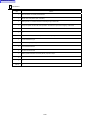
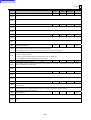
7.
SOLID (SD)
Address
(bit)
Outline
SD1 - SD48
—
SD49
Machine coordinate selection
SD50
Table type
SD51 - SD96
—
SD97
Distance of model movement per time
SD98
Amount of model rotation per time
SD99 SD124
—
2-27
2
Return to Library
2
PARAMETER
2-2-2
Machine parameter
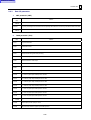
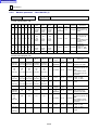
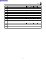
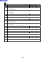
1.
CALL MACRO (J)
Address
(bit)
Outline
J1 - J40
G-code macroprogram call
J41 - J80
M-code macroprogram call
J81 - J90
—
J91 - J107
Parameter for system internal setting
J108 - J144
—
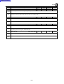
2.
Setting prohibited
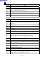
MEASURE (K)
Address
(bit)
Outline
K1
Rotational radius of the C-axis
K2
Minimum rotational angle
K3
Shaping control axis
K4 - K6
—
K7
Unbalanced axis
K8
—
K9
—
K10
Fixed value (0)
K11
Selection of language to be displayed
K12
Fixed value (0)
K13
Measurement skip feed rate (X-axis, Z-axis)
K14
Measurement approach speed (X-axis, Z-axis)
K15
Measurement skip speed (C-axis)
K16
Measurement approach speed (C-axis)
K17
Specification of measuring tolerance (lower limit) [valid only for L106 bit 6 = 1]
K18
Specification of measuring tolerance (upper limit) [valid only for L106 bit 6 = 1]
K19
Measurement stroke for workpiece measurement
K20
Measurement stroke for tool nose measurement
2-28
Return to Library
PARAMETER
Address
(bit)
Outline
K21
Coefficient to determine rotation angle when retrying measurement C reference face
K22
Measurement retry frequency when retrying reference face C measurement
K23
Retry frequency for workpiece measurement
K24 - K28
Predetermined value
K29
Simultaneous control: Delay counter for automatic correction of synchronizing errors
K30
Approach speed for laser tool length measurement
K31
Approach speed for laser tool diameter measurement
K32
Pre-measuring speed for laser tool length measurement
K33
Pre-measuring speed for laser tool diameter measurement
K34
Pre-measuring spindle speed for laser tool length measurement
K35
Pre-measuring spindle speed for laser tool diameter measurement
K36
Parameter for system internal setting
K37
External deceleration speed
K38
Work number called during S-code macroprogram appointment
K39
Work number called during T-code macroprogram appointment
K40
Work number called during second auxiliary function macroprogram appointment
K41
G31 skipping speed
K42
G31.1 skipping speed
K43
G31.2 skipping speed
K44
G31.3 skipping speed
K45
G31.4 skipping speed
K46
Excessive pressing error spread (Amount of drooping)
K47
—
K48
—
K49
First number of the standby M-codes
K50
Total number of the standby M-codes
K51
M-code during workpiece measurement retry operation
K52
Parameter for system internal setting
Setting prohibited
Setting prohibited
2-29
2
Return to Library
2
PARAMETER
Address
(bit)
Outline
K53
Vocal output language selection
K54
Vocal output sound level
K55
Vocal output warning reference value
K56
Name of second auxiliary function
K57
Type of S-code macroprogram ap-pointment call
K58
Type of T-code macroprogram ap-pointement call
K59
Type of second auxiliary function macroprogram appointment call
K60
Fixed value (4)
K61
Fixed value (1)
K62
Fixed value (1)
K63
Fixed value (1)
K64
Fixed value (2)
K65
Fixed value (1)
K66
Fixed value (1)
K67
Fixed value (1)
K68
—
K69
G31.1 skip conditions
K70
G31.2 skip conditions
K71
G31.3 skip conditions
K72
G31.4 skip conditions
K73
G4 skip conditions
K74
Emergency stop contactor cutoff time (Safety supervisory function)
K75
Contactor control output device 1 (Safety supervisory function)
K76
Contactor control output device 2 (Safety supervisory function)
K77
Door switch input device (Safety supervisory function)
K78
Number of door switches (Safety supervisory function)
K79
Supervisory speed filtering time during servo-off (Safety supervisory function)
K80 - K84
—
2-30
Return to Library
PARAMETER
Address
(bit)
Outline
K85
Special linear acceleration/deceleration time constant for threading
K86 - K89
—
K90
Return override during synchronous tapping
K91
Alternative M-code for M96
K92
Alternative M-code for M97
K93
Fixed value (2)
K94
—
K95
K96
0
—
1
Fixed value (0)
2
Tool position compensation during T-command execution, performed/not performed
3
Coordinate system update during handle pulse interrupt, performed/not performed
4
Fixed value (0)
5
Acceleration/deceleration time constant for handle pulse feed
6
Software limits for G30 execution valid/invalid
7
In-position check valid/invalid
0
G0 command in-position check valid/invalid
1
Timing of manual free feed finish signal
2
Fixed value (0)
3
Axis/Cutting interlock alarm display, valid/invalid
4
Suppression of lost motion in modes other than the G1 command mode, valid/invalid
5
Fixed value (0)
6
Fixed value (0)
7
Fixed G0 inclination
K97
B-axis misalignment correction, name of parallel axis
K98
B-axis misalignment correction, name of orthogonal axis
K99
Dynamic offset, name of rotational axis
K100
Dynamic offset, name of parallel axis
2-31
2
Return to Library
2
PARAMETER
Address
(bit)
K101
K102
K103
K104
K105
Outline
Dynamic offset, name of orthogonal axis
0
—
1
—
2
Length of linear acceleration/deceleration filter II
3
Length of linear acceleration/deceleration filter II
4
Length of linear acceleration/deceleration filter II
5
Length of linear acceleration/deceleration filter II
6
Handling of the acceleration/deceleration filters for shape correction
7
Fixed value (0)
0
—
1
Synchronous control error auto-correction valid/invalid
2
—
3
DDB micron unit
4
Thermal displacement compensation interval
5
Output of S-code and T-code at restart
6
—
7
—
0
Output of a laser measurement B-axis 0-degree command after ATC, valid/invalid
1
Direction of the laser axis of the laser measuring instrument (L16/K104 bit 2)
2
Direction of the laser axis of the laser measuring instrument (Parallel to the Y-axis/X-axis)
3
Vocal output function valid/invalid
4
Type of voice
5
Vocal guidance for warm-up operation
6
Setting rapid feed override to 0% when cutting feed override is set to 0%
7
—
0
—
1
Fixed value (1)
2
S-code macro call invalid/valid
2-32
Return to Library
PARAMETER
Address
(bit)
K106
K107
Outline
3
T-code macro call invalid/valid
4
Second auxiliary function macro call invalid/valid
5
Fixed value (0)
6
Fixed value (0)
7
Input in millimeter/inch
0
Execution conditions for user macroprogram interrupt
1
Start timing for user macroprogram interrupt
2
Fixed value (0)
3
Pitch error setting
4
Fixed value (0)
5
Fixed value (0)
6
Fixed value (0)
7
Fixed value (0)
0
Fixed value (0)
1
—
2
—
3
—
4
—
5
—
6
Deceleration for arc valid/invalid
7
Fixed value (0)
K108
Permissible error range for synchronous control
K109
—
K110
Judgment angle near a singular point
K111
Clamping speed in safety supervisory mode 3
K112
—
K113
Machine type
2-33
2
Return to Library
2
PARAMETER
Address
(bit)
Outline
K114
Axis number of the horizontal axis in the rectangular coordinate system
K115
Axis number of the vertical axis in the rectangular coordinate system
K116
Axis number of the height axis in the rectangular coordinate system
K117
Rotational direction of the rotary axis
K118 - K120
—
K121
Axis number of the first rotary axis
K122
Horizontal axis rotational center offset of the first rotary axis
K123
Vertical axis rotational center offset of the first rotary axis
K124
Height axis rotational center offset of the first rotary axis
K125
Axis number of the second rotary axis
K126
Horizontal axis rotational center offset of the second rotary axis
K127
Vertical axis rotational center offset of the second rotary axis
K128
Height axis rotational center offset of the second rotary axis
K129 - K144
—
3.
TABLE (L)
Address
(bit)
Outline
L1
Stylus eccentricity of touch sensor (X-component)
L2
Stylus eccentricity of touch sensor (Y-component)
L3
Radius of stylus ball of touch sensor (X-component)
L4
Radius of stylus ball of touch sensor (Y-component)
L5
Z-axis stroke for tip position memory (TEACH function)
L6
Tool-breakage judgment distance for TBR function
L7
Tool-breakage restoration mode for TBR function
L8
Skipping stroke limit for MMS
L9
Selection of random ATC specifications
L10
Interval between magazine pockets
L11
Touch sensor’s interference direction
2-34
Return to Library
PARAMETER
Address
(bit)
Outline
L12
Tolerance for manual measurement
L13
Allowable angle for parallelism and right angle in manual measurement
L14
Escapement for straightness measurement
L15
Macro program number for straightness measurement
L16
Parameter for system internal setting
L17
—
L18
Presence/absence of tailstock
L19
—
L20
—
L21
Output type of index (rotary) table
L22
Data of the tool nose measurement sensor, Sensor width along the X-axis
L23
Data of the tool nose measurement sensor, Sensor width along the Z-axis
L24
Tool nose measurement sensor reference position, X-axis
L25
Tool nose measurement sensor reference position, Z-axis
L26
Tool nose measurement sensor reference position, Y-axis
L27
Timer setting for manual TOOL EYE measurement
L28
Amount of Z-axial escape from the approach point after TOOL EYE measurement
L29
Machine efficiency
L30
Selection of machining navigation case introduction messages
L31 - L36
—
L37
Minimum index angle of index table
L38
M/B-code for index of index table
L39
Selection of execution/non execution of indexing unit
L40
Availability of specification of index table angle in end unit
L41
Simultaneous operation of indexing unit with ATC
L42
Initial value of index table angle
L43
Indication of index table angle
Setting prohibited
2-35
2
Return to Library
2
PARAMETER
Address
(bit)
Outline
L44
Selection of automatic setting on/off for nose position correction of a drilling tool
L45
Index table angle command
L46
Maximum number of pallets in pallet changing unit
L47
To prepare or not to prepare next pallet change
L48
Number of long boring bars
L49
Simultaneous operation of pallet change with ATC
L50
Rewriting of head number
L51
Tool command system in MDI operation
L52
Writing of machining management data with macro variable
L53
Showing of program number in PALLET MANAGEMENT display
L54
Selection of automatic operation mode
L55
Spindle load meter display type
L56
Method of measurement of coordinates by tool edge memorizing function (TEACH)
L57
Rewriting of tool data during automatic operation
L58
Head index angle indication system
L59
Input selection for HEAD OFFSET display
L60
Head quantity
L61
Output timing of AHC and APC
L62
Head relay point X1
L63
Head relay point Y1
L64
Head relay point X2
L65
Head relay point Y2
L66
Return/No return to head indexing point Z
L67
Length between the end surface of the spindle and the center of head rotation
L68
Head correction value X
L69
Head correction value Y
L70
Axis movement from machining face on escapement
2-36
Return to Library
PARAMETER
Address
(bit)
Outline
L71
Shift of basic coordinate for oblique face machining
L72
—
L73
Time constant for shape coorection acceleration/deceleration filter 2
L74
Cutting feed rate for pre-interpolational acceleration/deceleration control
L75
Time constant for pre-interpolational linear control during cutting feed rate acceleration/deceleration
L76
Acceleration rate for high-speed cutting
L77
Angle for deceleration at corner before interpolation
L78
—
L79
In-position width for changeover of the synchronized-tapping gain
L80
—
L81
Fixed value (0)
L82
Table thickness
L83
Spindle head radius
L84
Correction value of alignment deviation X (Upper face)
L85
Correction value of alignment deviation Y (Upper face)
L86
Correction value of alignment deviation X (0-degree face)
L87
Correction value of alignment deviation Y (0-degree face)
L88
Correction value of alignment deviation X (90-degree face)
L89
Correction value of alignment deviation Y (90-degree face)
L90
Correction value of alignment deviation X (180-degree face)
L91
Correction value of alignment deviation Y (180-degree face)
L92
Correction value of alignment deviation X (270-degree face)
L93
Correction value of alignment deviation Y (270-degree face)
L94 - L97
—
L98
Max. tool length for laser tool length measurement
L99
Cycle time for saving the operational status management data
L100 - L105
—
2-37
2
Return to Library
2
PARAMETER
Address
(bit)
L106
L107
0
Measuring equipment selection
1
Selection of a rotational reference coordinate system for WPC-th
2
Selection of measuring equipment
3
Selection of whether workpiece measurement results and tool measurement results are to be stored into tool
data of the lower turret
4
Selection of whether to enable or disable the fixed amount compensation function
5
Selection of measurement execution timing
6
Selection of tool measurement operation
7
—
0
Tool path drawing
1
—
2
Tailstock type
3
Whether tail thrust is also to be displayed in pounds (lbs)
4
LBB No. setting for the grooving I.D. tool, threading I.D. tool, or touch sensor, valid/invalid
5
XYZ-axis operation for the first T-command after cycle start
6
A-axis operation for the first T-command after cycle start
7
—
L108
L109
L110
Outline
Fixed value (0)
0
Software limit 4 - Interference axial direction (1st set)
1
Software limit 4 - Interference axial direction (2nd set)
2
Software limit 4 - Interference axial direction (3rd set)
3
Software limit 4 - Interference axial direction (4th set)
4
—
5
—
6
—
7
—
0
Opposed-spindle lathe specifications
1
Vertically inverted spindle specifications
2-38
Return to Library
PARAMETER
Address
(bit)
Outline
2
Axis name of the secondary spindle
3
Whether to disable or enable the display of “section to be machined” in the milling tool sequence
4
Display of the BUFFER, REMAIN and POSITION information during coordinate conversion
5
—
6
—
7
Z-axis direction
L111
—
L112
—
L113
Interference check reference axis (1st set of axes)
L114
Interference check reference axis (2nd set of axes)
L115
Interference check reference axis (3rd set of axes)
L116
Interference check reference axis (4th set of axes)
L117
Interference check axis (1st set of axes)
L118
Interference check axis (2nd set of axes)
L119
Interference check axis (3rd set of axes)
L120
Interference check axis (4th set of axes)
L121
Interference clearance (1st set of axes)
L122
Interference clearance (2nd set of axes)
L123
Interference clearance (3rd set of axes)
L124
Interference clearance (4th set of axes)
L125
—
L126
Positioning direction of the head rotation - α-axis for oblique plane indexing
L127
—
L128
—
L129
Acceleration/deceleration filter (1st stage), G1 time constant
L130
Acceleration/deceleration filter (1st stage), G0 time constant
L131
Acceleration/deceleration filter (2nd stage), G1 time constant
2-39
2
Return to Library
2
PARAMETER
Address
(bit)
Outline
L132
Acceleration/deceleration filter (2nd stage), G0 time constant
L133 - L138
—
L139
Minimum usable tool diameter of the measurable chamfering tool
L140 - L144
—
4.
FEED VEL. (M)
Address
(bit)
Outline
M1
Rapid feed rate
M2
Feed rate for initial zero-point return
M3
Cutting feed rate limit
M4
Offset of machine coordinates system
M5
Second zero-point coordinating value
M6
Third zero-point coordinating value
M7
Fourth zero-point coordinating value
M8
Maximum software limit specified by manufacturer (+ direction)
M9
Maximum software limit specified by manufacturer (– direction)
M10
Command unit
M11
Coding of address of axis
M12
Coding of incremental axis
M13
Axis name (for display)
M14
Shifting distance of the watchdog-less home position
M15
Axis name (for axis name changing)
M16
Zero-point shift amount
M17
0
—
1
Unit of output from MCP to servo amplifier
2
Direction of machine zero-point return
3
Error correction schema with servo on
4
Type of axis
2-40
Return to Library
PARAMETER
Address
(bit)
M18
M19
M20
Outline
5
Rotational direction of servo motor (for movement in (+) direction)
6
—
7
Alarm/No alarm with axis removed
0
Type of C-axis
1
—
2
Machine zero-point position
3
—
4
Watchdog-less axis
5
X-axis current position display in radius/diameter
6
Automatic/manual simultaneous absolute-value updating
7
Absolute-value detection
0
—
1
—
2
—
3
In-position checking method
4
—
5
Homing operation starting position check
6
—
7
Backlash scheme to be adopted for watchdog-type returning to home position
0
Rotational direction of the rotation axis (Dynamic offset II)
1
—
2
—
3
—
4
—
5
—
6
—
7
—
2-41
2
Return to Library
2
PARAMETER
Address
(bit)
M21
M22
Outline
0
Rapid-feed acceleration/deceleration type, Linear acceleration/deceleration
1
Rapid-feed acceleration/deceleration type, First-order lag
2
Rapid-feed acceleration/deceleration type, Second-order lag
3
Rapid-feed acceleration/deceleration type, Exponential acceleration/linear deceleration
4
Cutting-feed acceleration/deceleration type, Linear acceleration/deceleration
5
Cutting-feed acceleration/deceleration type. First-order lag
6
Cutting-feed acceleration/deceleration type, Second-order lag
7
Cutting-feed acceleration/deceleration type, Exponential acceleration/linear deceleration
0
Deceleration time constant for rapid-feed exponential acceleration/linear deceleration
1
Type of stroke-end stop
2
Type of stroke-end stop
3
—
4
—
5
—
6
—
7
—
M23
—
M24
—
M25
Upper limit of inclined Y-axis access inhibition area (Soft limit 3)
M26
Lower limit of inclined Y-axis access inhibition area (Soft limit 3)
M27
Optimum acceleration control: Target speed
M28
—
M29
Rapid feed clamping speed 1 for superposition control
M30
Rapid feed clamping speed 2 for superposition control
M31
Cutting feed clamping speed for superposition control
M32
Safety speed for Safety supervisory mode 2
M33
Safety speed for Safety supervisory mode 3
2-42
Return to Library
PARAMETER
Address
(bit)
Outline
M34
Safety clamping speed for Safety supervisory mode 2
M35
Safety clamping speed for Safety supervisory mode 3
M36
Speed supervisory door selection
M37
Safety clamping speed reduction judgment coefficient
M38
Interference check distances for Intelligent Safety Shield, primary check distance
M39
Interference check distances for Intelligent Safety Shield, secondary check distance
M40 - M48
—
5.
TIME CONST. (N)
Address
(bit)
Outline
N1
Rapid-feed time constant (linear acceleration/deceleration)
N2
Cutting-feed time constant (linear acceleration/deceleration)
N3
Rapid-feed time constant (First-order lag)
N4
Time constant for post-interpolation rapid feed acceleration/deceleration filter
N5
Cutting-feed time constant (First-order lag)
N6
—
N7
OT time
N8
Creeping speed during initial zero-point return
N9
Amount of grid ignorance during initial zero-point return
N10
Grid spacing
N11
—
N12
Rapid-feed backlash
N13
Cutting-feed backlash
N14
—
N15
Width to which the machine posture change correction is to be applied
N16
Machine posture change correction value
N17
Servo amplifier channel number
N18
Servo amplifier rotary switch number
2-43
2
Return to Library
2
PARAMETER
Address
(bit)
Outline
N19
Axis system number
N20
—
N21
0
Linear-type rotational axis
1
Rotational axis shortcut
2
Fixed value (0)
3
Bi-directional pitch error correction
4
Reference axis for superposition control
5
Superposition axis for superposition control
6
Relative polarity of control axis
7
—
N22 - N24
—
N25
Time constant for deceleration rate calculation
N26
Accuracy coefficient for deceleration rate calculation
N27
Rapid feed time constant for superposition
N28
Cutting feed time constant for superposition
N29
Time constant for shape correction rapid feed acceleration/deceleration filter
N30
Time constant for cutting feed (for M881)
N31
Time constant for cutting feed (for M882)
N32
Time constant for cutting feed (for M883)
N33
Time constant for cutting feed (for M884)
N34
Time constant for cutting feed (for M885)
N35
Time constant for cutting feed (for M886)
N36 - N48
—
6.
Invalid/Valid
ANOTHER (S)
Address
(bit)
Outline
S1
—
S2
—
2-44
Return to Library
PARAMETER
Address
(bit)
Outline
S3
Feed forward gain for the MAZAK Precision Rapid Boring Tornado Option
S4
Feed forward gain
S5
Rotational center of the table
S6
Absolute position detection parameter
S7
Upper limit (on Z-axis) of machining range for table rotating machining Ι
S8
Feed-forward gain G00
S9
—
S10
Axis of rotation of the tilting table
S11
Corner position of the tilting table
S12
Axis of rotation of the tilting table (Used for the automatic program origin calculation function)
S13
G00 in-position width
S14
G01 in-position width
S15
Amount of reference position correction (Only for bidirectional pitch error correction)
S16
Unbalanced axis torque offset
S17
Torque limit buffer reduction ratio 1
S18
Torque limit buffer reduction ratio 2
S19
Tool change completion position of the long boring bar end tool
S20
—
S21
—
S22
Cutting feed clamping speed during tool tip point control
S23
Reference workpiece zero point
S24 - S48
—
2-45
2
Return to Library
2
PARAMETER
7.
SPINDLE (SA)
Address
(bit)
Outline
SA1 - SA8
Maximum RPM of spindle in each speed range (range 1 to 8)
SA9 - SA16
Constants for calculating each gear speed of the spindle (range 1 to 8)
SA17 - SA24
Maximum RPM of spindle during tapping cycle (range 1 to 8)
SA25 - SA32
Spindle speed during gear shifting (range 1 to 8)
SA33 - SA40
Acceleration/deceleration time constant for the synchronous tapping (range 1 to 8)
SA41
Spindle orientating speed
SA42
Minimum spindle speed
SA43
Channel number for the spindle amplifier
SA44
Spindle amplifier rotary switch number
SA45
SA46
SA47
0
Spindle speed range changing method, in relation to switching the torque factors for auto-pecking of the
cutting load detection type
1
Spindle speed range changing method, in relation to switching the torque factors for auto-pecking of the
cutting load detection type 2
2
Homing direction for synchronous tapping
3
Homing direction for synchronous tapping
4
Defines the specified direction as the Z-phase detection direction
5
Spindle index gear correction
6
—
7
—
0
Direction of orientation
1
Direction of orientation
2
C-axis position control changeover type
3
Synchronous tapping position control changeover type
4
Z-phase detection direction
5
C-axis homing direction
6
C-axis homing direction
7
Synchronous tapping command polarity
0
—
2-46
Return to Library
PARAMETER
Address
(bit)
1
2
3
4
5
2
Outline
—
—
—
—
—
6
—
7
Considering/Ignoring the spindle/motor gear ratio
SA48
Encoder signal input destination
SA49
Speed attainment detection width
SA50
Spindle type
SA51
Number of gears on spindle
SA52
Turning spindle type
SA53
Spindle 1/4h (1/2h) rated torque for auto-pecking of the cutting load detection type — L coils
SA54
Spindle 1/4h (1/2h) rated torque for auto-pecking of the cutting load detection type — H coils
SA55
Spindle 1/4h (1/2h) rated torque for auto-pecking of the cutting load detection type — Spindle gear position 3
SA56
Spindle 1/4h (1/2h) rated torque for auto-pecking of the cutting load detection type — Spindle gear position 4
SA57
Spindle viscous friction coefficient “cms” for auto-pecking of the cutting load detection type — Range 1
SA58
Spindle viscous friction coefficient “cms” for auto-pecking of the cutting load detection type — Range 2
SA59
Spindle viscous friction coefficient “cms” for auto-pecking of the cutting load detection type — Range 3
SA60
Spindle viscous friction coefficient “cms” for auto-pecking of the cutting load detection type — Range 4
SA61
Spindle coulombic friction coefficient “fms” for auto-pecking of the cutting load detection type — Range 1
SA62
Spindle coulombic friction coefficient “fms” for auto-pecking of the cutting load detection type — Range 2
SA63
Spindle coulombic friction coefficient “fms” for auto-pecking of the cutting load detection type — Range 3
SA64
Spindle coulombic friction coefficient “fms” for auto-pecking of the cutting load detection type — Range 4
SA65
Cutting force calculation filter for auto-pecking of the cutting load detection type
SA66
Maximum permissible speed of the rotational axis for polygonal/hobbing machining
SA67 - SA73
Revolutions in the following spindle output diagrams:
MACHINING NAVIGATION-RESULT/MACHINING NAVIGATION-PPEDICTION/Monitoring Functions
2-47
Return to Library
2
PARAMETER
Address
(bit)
Outline
SA74 - SA80
Output in the following spindle output diagrams:
MACHINING NAVIGATION-RESULT/MACHINING NAVIGATION-PPEDICTION/Monitoring Functions
SA81
Spindle limit speed selection for spindle position control time constants — Limit speed 1
SA82
Spindle limit speed selection for spindle position control time constants — Limit speed 2
SA83
Spindle limit speed selection for spindle position control time constants — Limit speed 3
SA84
Spindle position control time constants — Time constant 1
SA85
Spindle position control time constants — Time constant 2
SA86
Spindle position control time constants — Time constant 3
SA87
Spindle speed operating time constant changeover revolutions 1
SA88
Spindle speed operating time constant changeover revolutions 2
SA89
Spindle speed operating time constant 1
SA90
Spindle speed operating time constant 2
SA91
Spindle speed operating time constant 3
SA92
Z-phase detection speed
SA93
Amount of synchronous tapping zero point shifting
SA94
Homing speed for synchronous tapping
SA95
Maximum revolutions in manual operation mode
SA96
Amount of orientation position shifting
SA97
Reduction ratio of the synchronous tapping time constant for high-speed synchronous tapping
SA98
—
SA99
Orientation time constant
SA100 SA113
—
SA114
Spindle speed supervisory mode 2 for safety supervision
SA115
Spindle speed supervisory mode 3 for safety supervision
SA116
Spindle safety clamping mode 2 for safety supervision
SA117
Spindle safety clamping mode 3 for safety supervision
SA118
Selecting the spindle door of the spindle whose speed is to be monitored
SA119
Deceleration judgment coefficient on safety speed clamping of the spindle to be supervised for safety
2-48
Return to Library
PARAMETER
Address
(bit)
Outline
SA120
PLG pulse rate for spindle index gear tooth correction
SA121
Amount of branching [1] point correction for spindle index gear tooth
SA122
Amount of branching [2] point correction for spindle index gear tooth
SA123
Amount of branching [3] point correction for spindle index gear tooth
SA124
Amount of branching [4] point correction for spindle index gear tooth
SA125
Amount of branching [5] point correction for spindle index gear tooth
SA126
Amount of branching [6] point correction for spindle index gear tooth
SA127
Amount of branching [7] point correction for spindle index gear tooth
SA128
Amount of branching [8] point correction for spindle index gear tooth
SA129 SA137
—
SA138
Number of spindle gears
SA139
Number of motor gears
SA140
Turret indexing gear ratio
SA141 SA143
—
SA144
0
—
1
—
2
—
3
—
4
—
5
—
6
Spindle gear changeover valid
7
Turret indexing valid
2-49
2
Return to Library
2
PARAMETER
8.
BARRIER (BA)
Address
(bit)
Outline
BA1
Chuck outside diameter (for chuck barrier) — No. 1 turning spindle
BA2
Chuck width (for chuck barrier) — No. 1 turning spindle
BA3
Chuck inside diameter (for chuck barrier) — No. 1 turning spindle
BA4
EIA program workpiece outside diameter
BA5
Chuck outside diameter (for chuck barrier) — No. 2 turning spindle
BA6
Chuck width (for chuck barrier) — No. 2 turning spindle
BA7
Chuck inside diameter (for chuck barrier) — No. 2 turning spindle
BA8
Tail body outside diameter (for tail barrier)
BA9
Tail body length (for tail barrier)
BA10
Tail spindle outside diameter (for tail barrier)
BA11
Length with tail spindle at back end (for tail barrier)
BA12
Tail head outside diameter (for tail barrier)
BA13
Tail head length (for tail barrier)
BA14
Tail head taper angle (for tail barrier)
BA15
Tail head biting diameter (for tail barrier)
BA16
Tail barrier, tail extruding length
BA17
Tail barrier, workpiece length
BA18
Tail barrier, tail reversing position Z
BA19
Distance from the Z-axis machine zero point to the spindle edge — No. 1 turning spindle
BA20
Distance from the Z-axis machine zero point to the spindle edge — No. 2 turning spindle
BA21
Jaw number for EIA program barrier — No. 1 turning spindle
BA22
Jaw number for EIA program barrier — No. 2 turning spindle
BA23
Turret outline
BA24
Turret width
BA25
Turret reference position X
BA26
Turret reference position Z
2-50
Return to Library
PARAMETER
Address
(bit)
Outline
BA27
Tool holder mounting position — Type 1
BA28
Tool holder width in X-axis direction — Type 1
BA29
Tool holder width in Z-axis direction — Type 1
BA30
Tool holder mounting position — Type 2
BA31
Tool holder width in X-axis direction — Type 2
BA32
Tool holder width in Z-axis direction — Type 2
BA33
Tool holder mounting position — Type 3
BA34
Tool holder width in X-axis direction — Type 3
BA35
Tool holder width in Z-axis direction — Type 3
BA36
Tool holder mounting position — Type 4
BA37
Tool holder width in X-axis direction — Type 4
BA38
Tool holder width in Z-axis direction — Type 4
BA39
EIA tool barrier, tool holder mounting position
BA40
EIA tool barrier, tool holder width X
BA41
EIA tool barrier, tool holder width Z
BA42
Barrier type
BA43
First tool number (in the 1st set of tools)
BA44
Number of tools (in the 1st set of tools)
BA45
First tool number (in the 2nd set of tools)
BA46
Number of tools (in the 2nd set of tools)
BA47
Turret type
BA48
Axis name of the head to be rotated
BA49
Axis number of the inclined axis
BA50
Fundamental axis number
BA51
Inclined-axis control, vector of virtual Y
BA52
Inclined-axis control, vector of real X
BA53
Inclined-axis control, vector ot real Y
2-51
2
Return to Library
2
PARAMETER
Address
(bit)
Outline
BA54
Selection of work spindle for hobbing
BA55
Turning spindle number for polygonal machining (D1)
BA56
Turning spindle number for polygonal machining (D2)
BA57
Turning spindle number for polygonal machining (D3)
BA58
Turning spindle number for polygonal machining (D4)
BA59
Spindle forward rotation M-code for tapping cycle
BA60
Spindle reverse rotation M-code for tapping cycle
BA61
Amount of runout of the B-axis center
BA62
Amount of offset for the B-axis — spindle distance
BA63
Holder angle of angle tool holder
BA64
B-axis tool reference position X
BA65
B-axis tool reference position Z
BA66
Deceleration area Z
BA67
Measuring area Z
BA68
Deceleration area X
BA69
Measuring area X
BA70
Distance between the reference points on both turrets
BA71
System number to be used when argument L is omitted from G112
BA72
—
BA73
Barrier valid/invalid 1 (chuck, sub-chuck, tailstock)
BA74
Barrier valid/invalid 2 (Lower turret, work rest)
BA75 - BA78
Barrier setup turret reference position
BA79 - BA82
Barrier setup chuck reference position 1
BA83 - BA86
Barrier setup chuck reference position 2
BA87 - BA90
Tail barrier reference position
BA91
Distance from spindle edge to partition plate
BA92
Central position X when viewed from machine zero point
2-52
Return to Library
PARAMETER
Address
(bit)
Outline
BA93
Upper/lower turret tool angle difference (HD1)
BA94
Upper/lower turret tool angle difference (HD2)
BA95
Tool nose measurement, sensor width along the X-axis
BA96
Tool nose measurement, sensor width along the Z-axis
BA97
Tool nose measurement, X-coordinate of the sensor’s reference point
BA98
Tool nose measurement, Y-coordinate of the sensor’s reference point
BA99
Tool nose measurement, Z-coordinate of the sensor’s reference point
BA100
Tool nose measurement, X-coordinate of the sensor’s reference point (for lower turret/HD2)
BA101
Tool nose measurement, Y-coordinate of the sensor’s reference point (for lower turret/HD2)
BA102
Tool nose measurement, Z-coordinate of the sensor’s reference point (for lower turret/HD2)
BA103
Tool nose measurement, sensor width along the X-axis (for lower turret/HD2)
BA104
Tool nose measurement, sensor width along the Z-axis (for lower turret/HD2)
BA105
Adjustment “FdT” for W-axis thrust hold
BA106
Dead zone
BA107
Filter
BA108
W-axis thrust hold droop
BA109
Offset amount (X) during automatic tool setting value calculation
BA110
Offset amount (Z) during automatic tool setting value calculation
BA111
Pre-interpolation acceleration/deceleration time constant for time constant changeover M-code (M881)
BA112
Pre-interpolation acceleration/deceleration time constant for time constant changeover M-code (M882)
BA113
Pre-interpolation acceleration/deceleration time constant for time constant changeover M-code (M883)
BA114
Pre-interpolation acceleration/deceleration time constant for time constant changeover M-code (M884)
BA115
Pre-interpolation acceleration/deceleration time constant for time constant changeover M-code (M885)
BA116
Pre-interpolation acceleration/deceleration time constant for time constant changeover M-code (M886)
BA117 BA124
—
BA125
0
EIA tailstock barrier, tailstock usage valid/invalid
1
Tailstock present/absent
2-53
2
Return to Library
2
PARAMETER
Address
(bit)
Outline
2
EIA tool barrier, tool holder present/absent
3
Barrier tool nose position (EIA, automatic)
4
Setting of BA11 is handled as tailstock extruding length, valid/invalid
5
Output of spindle revolution M-code specified in same block as synchronous tapping, valid/invalid
6
—
7
—
0
System to be made valid without system selection for queuing
1
Y-axis interference type
2
Y-axis moving range display
3
Tool command scheme
4
FLASH tool valid/invalid
5
Milling spindle orientation command (M219), output/no output
6
—
7
—
BA127 BA132
—
BA126
2-54
Return to Library
PARAMETER
2-2-3
2
Data I/O parameter
1.
CMT parameter (CMT)
Address
(bit)
Outline
CMT1 CMT24
—
CMT25
Type of processing to be executed if the tool quantity data within the NC memory mismatches that of the CMT
CMT26 CMT32
—
2.
TAPE parameter (TAP)
Address
(bit)
Outline
TAP1
Type of terminator
TAP2
Terminator code 1
TAP3
Terminator code 2
TAP4
Output of CR during ISO code punching
TAP5
DC code parity
TAP6
Feed section DC code output
TAP7
—
TAP8
—
TAP9
“[” code for paper tape reader/puncher for EIA
TAP10
“]” code for paper tape reader/puncher for EIA
TAP11
“#” code for paper tape reader/puncher for EIA
TAP12
“∗” code for paper tape reader/puncher for EIA
TAP13
“=” code for paper tape reader/puncher for EIA
TAP14
“:” code for paper tape reader/puncher for EIA
TAP15
“(” code for paper tape reader/puncher for EIA
TAP16
“)” code for paper tape reader/puncher for EIA
TAP17 TAP24
—
TAP25
Paper tape puncher parity-V check
TAP26
Bit parameter related to paper tape reader/puncher
2-55
Return to Library
2
PARAMETER
Address
(bit)
Outline
TAP27
Bit parameter related to program end code (M) for paper tape reader
TAP28
—
TAP29
Number of characters in feed section for paper tape puncher
TAP30
Number of characters in the space between O-number and program for paper tape puncher
TAP31
Number of characters in the space between programs for paper tape puncher
TAP32
—
3.
DNC parameter (DNC)
Address
(bit)
Outline
DNC1
Type of terminator
DNC2
Terminator code 1
DNC3
Terminator code 2
DNC4
—
DNC5
DC code parity
DNC6 DNC8
—
DNC9
Number of NC transmission retries during DNC file transfer
DNC10
Number of NC reception retries during DNC file transfer
DNC11
Number of NC transmission/reception retries during DNC command message transfer
DNC12
@ waiting time during DNC transmission
DNC13
“∗”, TEXT waiting time during DNC transmission
DNC14
EOT waiting time during DNC transmission
DNC15
NC stop time after reception of !
DNC16
NC reset time after digital-out
DNC17
NC stop time from reception
DNC18
DNC command reply message waiting time
DNC19
DNC machine number
DNC20
NC transmission stop time of DNC (from reception to transmission)
DNC21
NC transmission stop time of DNC (from transmission to transmission)
2-56
Return to Library
PARAMETER
Address
(bit)
2
Outline
DNC22 DNC24
—
DNC25 0
Type of processing to be executed if the tool quantity data within the NC memory mismatches that which has
been transferred from the DNC memory
1
—
2
Handling of tool data and tool files in the M PLUS format, valid/invalid
3
—
4
—
5
—
6
—
7
—
DNC26 0
After program reception, a search is made/not made for the work number of that program.
1
Details of an alarm occurring in DNC are displayed or not.
2
Loading of programs having the same work number as that of the registered program in NC becomes
impossible or not.
3
The function of the PROGRAM LOCK/ ENABLE switch is released or not.
4
—
5
Three digit G-format and G10 format codes input/output for MAZAK data transfer protocol
6
Binary to ASCII format input/output of MAZAK data transfer protocol
7
All programs having work numbers smaller than No. 9000 are erased/not erased at the start of program
reception.
DNC27
—
DNC28
—
DNC29
Number of retry times with detection of a physical error
DNC30
Tool data/tool file message format
DNC31
—
DNC32
—
2-57
Return to Library
2
PARAMETER
4.
Other (IOP/DPR/IDD)
Address
(bit)
Outline
IOP1 - IOP4
—
IOP5
Loading a program(s) of the same work number, alarm without overwriting/overwriting
IOP6
—
IOP7
Data entry for communication with the magazine-side display unit
IOP8
—
IOP9
Number of pitch error axes during text output
IOP10 IOP16
—
DPR1
Baud rate
DPR2
Stop bit
DPR3
—
DPR4
Data bit
DPR5 DPR7
—
DPR8
ISO code CR output and the output file size
DPR9
Method of handshaking
DPR10
DC code parity
DPR11
Feed section DC code output
DPR12
Waiting time
DPR13
Output format
DPR14
Selection of an output destination port
DPR15
Number of characters or the number of lines in feed section
DPR16
—
IDD1 IDD16
—
2-58
Return to Library
PARAMETER
2-3
Detailed Description
2-3-1
Structure of the parameter list
Each parameter list is written in the following format:
[1]
Classification
Address
[2]
Display title
Meaning
Description
[4]
[9]
[3]
Program type
Conditions
Unit
Setting range
[5]
[6]
[7]
[8]
[1]
Classification of parameters (USER, MACHINE or DATA I/O)
[2]
Characters displayed at the upper part of the screen
[3]
Parameter address displayed on the screen
- Bit input type parameters have the bit No. shown in the parentheses below address.
Example:
Setting value for parameter
P1 (bit 0) is indicated here
Address
P1
(bit 0)
P1
[4]
Meaning of the parameter
[5]
Applicable program
Bit 0
Bit 1
Bit 2
Bit 3
Bit 4
Bit 5
Bit 6
Bit 7
M....................Effective only for MAZATROL programs
E ....................Effective for EIA/ISO programs
M, E ...............Effective for MAZATROL programs and EIA/ISO programs
2-59
2
Return to Library
2
PARAMETER
[6]
Conditions under which a changed parameter becomes valid
Example 1: “Immediate” designates that new parameter value becomes effective upon
parameter change.
Example 2:
“At power on” designates that new parameter value will become effective
after procedure below.
1. Change parameter setting value.
(By procedure similar to changing of ordinary data)
!
2. Press power off button on the operation panel.
!
3. Press power on button on the operation panel.
Example 3:
In the parameter list, “At I/O startup” means that the system operates at the
parameter data entered before the start of I/O. If the parameter data is
modified during I/O operation, the new data will not become valid until the I/O
operation has been completed.
[7]
Units of data displayed
[8]
Allowable range of data
[9]
Details or meaning of the parameter
2-60
Return to Library
PARAMETER
2-3-2
User parameter
POINT (D)
USER
Classification
Address
2
POINT
Display title
Meaning
Description
Height of the second R-point
Initial point
D1
Second R-point
MPL001
Height of the second R-point during point
machining
D1
The height of the R-point during point machining is basically D41,
however, it is changed to D1 under the following conditions.
Tool sequence
Program type
M
Conditions
Immediate
Unit
0.1 mm/0.01 inch
Setting range
–999 to 999
Conditions
Drill
- Bit 6 of parameter D91 is set to 1 (D1 valid).
- There is a spot drill in the pre-machining tool
sequence of the same unit.
Reamer
- Bit 2 of parameter D92 is set to 1 (D1 valid).
- There is a chamfering cutter in the premachining tool sequence of the same unit.
However, when a drill is included in the pre-machining tool sequence in
case of a drilling tool sequence, the height is changed to D42.
(!D42)
The nominal diameter of a spot-machining tool that is automatically set
during automatic tool development.
Example:
Nominal diameter of spot-machining tool
SNo.
1
TOOL
CTR-DR
D2
NOM-φ No.
20.
HOLE-φ
10.
HOLE-DEP
"
↑
D2
Program type
M
Conditions
Immediate
Unit
1 mm/0.1 inch
Setting range
0 to 99
Z-axis feed dwell time at the hole bottom in a spot-machining cycle. Set
this time in spindle revolutions.
When the spot-machining tool reaches
the hole bottom, the Z-axis will firstly stop
moving until the spindle makes D3
revolutions, and then return to the
original position at the rapid feed rate.
Number of revolutions during dwell at hole
bottom in spot-machining cycle
D3
Program type
M
Conditions
Immediate
Unit
1 revolution
Setting range
0 to 9
3
MPL002
2-61
Return to Library
2
PARAMETER
USER
Classification
Address
POINT
Display title
Meaning
Description
Element used to set the maximum spot-chamfering hole diameter (d)
during automatic tool development
Spot-chamfering occurs if
d ≤ D2 – D4.
If d > D2 – D4, the chamfering
cutter is developed automatically.
D2
Maximum allowable spot-chamfering hole
diameter element
d
D4
Program type
M
Conditions
Immediate
Unit
0.1 mm/0.01 inch
Setting range
0 to 99
0
MPL003
The feed rate of a tool as it is being passed through the prehole during an
inversed spot-facing cycle
Note: 0.5 mm/rev if this parameter setting is 0.
Prehole through speed during inversed
spot-facing
D5
At the feedrate of D5
Program type
M
Conditions
Immediate
Unit
100 mm/min / 10 inch/min
Setting range
0 to 99
MPL004
Element used to automatically set drill-machining cycles during automatic
tool development
Machining cycle
Conditions
Drill-machining cycle setting element
Drilling cycle
D6
D7
Program type
M
Conditions
Immediate
Unit
—
Setting range
0 to 9
DEPTH
DIA
≤ D6
≤ D7
High-speed deep-hole
drilling cycle
D6 <
DEPTH
DIA
Deep-hole drilling cycle
D7 <
DEPTH
DIA
2-62
Return to Library
PARAMETER
USER
Classification
Address
2
POINT
Display title
Meaning
Description
Element used to automatically set the number of drills which are
automatically developed according to the hole diameter of the drill unit
Number of drills
developed
Maximum diameter of holes machinable on
one drill
Conditions
DIA ≤ D8
1
D8
Program type
M
Conditions
Immediate
Unit
1 mm/0.1 inch
Setting range
0 to 99
2
D8
< DIA ≤ D9
3
D9
< DIA ≤ D10
Alarm
D10 < DIA
Maximum diameter of holes machinable on
two drills
D9
Program type
M
Conditions
Immediate
Unit
1 mm/0.1 inch
Setting range
0 to 99
Maximum diameter of holes machinable on
three drills
D10
Program type
M
Conditions
Immediate
Unit
1 mm/0.1 inch
Setting range
0 to 99
Element used to automatically set the hole-drilling, endmilling, and boring
depths during automatic tool development of inversed spot-facing,
tapping, back-boring, through-hole drilling, through-hole counter-boring,
and spot-faced tapping units
Through-hole/tap-prehole machining
overshoot
DEPTH
D11
DEPTH
D11
D11
MPL005
Program type
M
Conditions
Immediate
Unit
0.1 mm/0.01 inch
Setting range
0 to 99
Example:
SNo.
1
TOOL
CTR-DR
NOM-φ
10.
No.
HOLE-φ
10.
HOLE-DEP
21. ← (DEPTH + D11)
Note: See also parameter D30 for tapping units.
2-63
Return to Library
2
PARAMETER
USER
Classification
Address
POINT
Display title
Meaning
Description
Element used to automatically set the hole-drilling depth during automatic
tool development of stop-hole counter-boring and stop-hole boring units
DEPTH
Stop-hole machining hole-bottom clearance
D12
MPL006
D12
Example:
SNo.
Program type
M
Conditions
Immediate
Unit
0.1 mm/0.01 inch
Setting range
0 to 99
1
TOOL
NOM-φ
DRILL
10.
No. HOLE-φ
HOLE-DEP
19.
↑
(DEPTH – tool tip compensation – D12)
10.
Note:
This parameter is invalid when the residual hole diameter is not 0.
Hole diameter is automatically set during automatic tool development
when spot-chamfering is not to be performed.
D13
Spot-machining hole diameter
(fixed value)
D13
MPL007
Program type
M
Conditions
Immediate
Unit
1 mm/0.1 inch
Setting range
0 to 99
Example:
SNo.
1
TOOL
CTR-DR
NOM-φ No.
20.
HOLE-φ
HOLE-DEP
10.
"
D13
Element used to automatically set the depth-of-cut per drilling operation
during automatic tool development
Depth-of-cut setting element for drilling
(ALMINUM)
D14
Program type
M
Conditions
Immediate
Unit
0.1
Setting range
0 to 10
HOLE-φ × D14 : when the material of the stock workpiece is AL
(aluminum) in article MAT. 6
HOLE-φ × D15 : when the material of the stock workpiece is other than
AL in article MAT. 6
Depth-of-cut setting element for drilling
(except AL)
D15
Program type
M
Conditions
Immediate
Unit
0.1
Setting range
0 to 10
2-64
Return to Library
PARAMETER
USER
Classification
Address
2
POINT
Display title
Meaning
Description
Z-axis feed dwell time at the hole bottom in the chamfering cycle of
chamfering cutter or spot-machining tool. Set this time in spindle
revolutions.
Number of revolutions during dwell at hole
bottom for chamfering cutter or spotmachining tool in chamfering cycle
When the chamfering cutter reaches the
hole bottom, the Z-axis will firstly stop
moving until the spindle makes D16
revolutions, and then return to the
original position at the rapid feed rate.
D16
Program type
Note:
This parameter is invalid for chamfering
with true-circle processing.
M
Conditions
Immediate
Unit
1 revolution
Setting range
0 to 9
(Stops at hole bottom.)
MPL008
The clearance in order to prevent tool interference with a wall of the
workpiece or with the hole bottom during a chamfering cycle
D17
Interference clearance of chamfering cutter
D17
Interferes.
Program type
M
Conditions
Immediate
Unit
0.1 mm/0.01 inch
Setting range
0 to 99
D17
MPL009
Interferes.
The feed rate at which the tool is returned from the hole bottom during
reaming or boring.
D18
Return feed rate for reaming or boring
(cycle 3)
D18
MPL010
Program type
M
Conditions
Immediate
Unit
100 mm/min / 10 inch/min
Setting range
0 to 9
Notes:
1. Valid only when the setting of DEPTH for the reamer (tool sequence)
is G01.
2. Valid only when the setting of PRE-DIA for the boring tool (tool
sequence) is CYCLE 3.
3. If this parameter is 0, the tool is returned at the same feed rate as that
of cutting.
Z-axis feed dwell time at the hole bottom in an end milling cycle. Set this
time in spindle revolutions.
When the end mill reaches the hole
bottom, the Z-axis will firstly stop
moving until the spindle makes D19
revolutions, and then return to the
original position at the rapid feed rate.
Number of revolutions during dwell at hole
bottom for end milling
D19
Program type
M
Conditions
Immediate
Unit
1 revolution
Setting range
0 to 999
(Stops at hole bottom.)
2-65
Note:
This parameter is invalid for true-circle
processing.
MPL011
Return to Library
2
PARAMETER
USER
Classification
Address
POINT
Display title
Meaning
Description
Element used to automatically set the radial depth-of-cut per end milling
operation
Depth-of-cut = nominal diameter × D20
Radial depth-of-cut setting element for end
milling
Depth-of-cut is automatically set according to the value of this parameter
when nominal diameter of the end mill is input.
Example:
D20
SNo. TOOL NOM-φ No. HOLE-φ HOLE-DEP PRE-DIA PRE-DEP RGH DEPTH
1 END MILL 20.
40.
10.
30.
0. 12.
"
Program type
M
Conditions
Immediate
Unit
1%
Setting range
0 to 100
Reference bottom-finishing allowance for
end milling
(NOM-φ × D20)
The reference value for calculation of a bottom-finishing allowance which
corresponds to the roughness level of the end milling (tool sequence). The
finishing allowance in the case of roughness level 4 becomes the value of
this parameter, and the values for all other roughness levels are set using
the expressions listed in the table below.
Roughness
0 to 3
4
5
6
7
8
9
D21
Program type
M
Conditions
Immediate
Unit
0.1 mm/0.01 inch
Setting range
0 to 99
Bottom-finishing allowance
0.0
D21
D21 × 0.7
D21 × 0.7 × 0.7
D21 × 0.7 × 0.7 × 0.7
D21 × 0.7 × 0.7 × 0.7 × 0.7
D21 × 0.7 × 0.7 × 0.7 × 0.7 × 0.7
Dwell time at the hole bottom or at the R-point. This value is valid when 1
is set for bit 0, 1 or 2 of parameter D91.
Tapping-cycle dwell time
D22
Program type
M
Conditions
Immediate
Unit
0.01 sec.
Setting range
0 to 99
Note:
This parameter is valid only when the setting for roughness (RGH) of
tapping (tool sequence) is FIX.
The excess amount of prehole diameter over nominal diameter that is
used to specify whether the Z-axis is to be moved at a rapid feed rate or at
a cutting feed rate during true-circle processing with the end mill
Prehole clearance for end milling
D23
D23
D23
Program type
M
Conditions
Immediate
Unit
1 mm/0.1 inch
Setting range
0 to 999
Cutting feed
2-66
Rapid feed
MPL012
Return to Library
PARAMETER
USER
Classification
Address
2
POINT
Display title
Meaning
Description
Z-axis feed dwell time at the hole bottom in a boring cycle. Set this time in
spindle revolutions.
When the boring bar reaches the hole
bottom, the Z-axis will firstly stop moving
until the spindle makes D24 revolutions,
and then the spindle orientation will be
performed.
Number of revolutions during dwell at hole
bottom for boring
D24
Note:
Program type
This parameter is invalid if the roughness
(RGH) of the boring (tool sequence) is 0.
M
Conditions
Immediate
Unit
1 revolution
Setting range
0 to 9
MPL013
(Stops at hole bottom.)
The amount of relief provided for the tip of a boring bar to be kept clear of
the hole wall after spindle orientation
D25
Boring-bar tip relief
D25
During boring
Program type
M
Conditions
Immediate
Unit
0.1 mm/0.01 inch
Setting range
0 to 99
During returning
MPL014
Notes:
1. Valid only when the setting for the prehole diameter of the boring (tool
sequence) is CYCLE 1.
2. For the relief direction of the tool tip, see the description of bit 3 and bit
4 of I14.
The distance which the boring or back-boring tool is returned at the same
feed rate as for cutting after the tool has reached the hole bottom
Returning distance from hole bottom for
boring or back-boring
D26
D26
MPL015
Program type
M
Conditions
Immediate
Unit
0.1 mm/0.01 inch
Setting range
0 to 99
[1]Has reached the
hole bottom.
—
D27
—
Conditions
—
Unit
—
Setting range
—
[3] Returned at a
rapid feedrate.
Note:
Not valid if the setting for the roughness (RGH) of the boring (tool sequence)
is 1.
Invalid
Program type
[2] Returned at the
same feedrate.
2-67
Return to Library
2
PARAMETER
USER
Classification
Address
POINT
Display title
Meaning
Description
The distance which the boring bar is fed in at 70% of the original feed rate
to finish the hole bottom
Bottom-finishing amount of boring
D28
D28
Program type
M
Conditions
Immediate
Unit
0.1 mm/0.01 inch
Setting range
0 to 99
MPL016
The feed rate is reduced to 70% of the original value before the hole
bottom is reached.
Note:
Not valid if the setting for the roughness (RGH) of the boring (tool sequence)
is 1.
The time required for a chip removal tool to complete a chip removal
operation after the tool has been positioned to the hole
Chip removal time
D29
Program type
M
Conditions
Immediate
Unit
1 sec.
Setting range
0 to 99
To set number of incomplete threads in tapping cycle for metric screws
and unified screws. In tapping, internal thread is tapped extra for the depth
of (D30 × pitch) in the direction of Z.
This is also used as an element for automatically determining hole-drilling
depth (HOLE-DEP) in the automatic tool development of the tapping unit.
DEPTH
D30 × Pitch
Number of incomplete threads in tapping
cycle
D30
D11
MPL07
Example:
SNo.
1
TOOL
NOM-φ
DRILL
10.
No.
HOLE-φ
10.
HOLE-DEP
19.
↑
{DEPTH + D11 + (D30 × pitch)}
[Related parameter]
D43: Number of incomplete threads in tapping cycle for piped screws
Program type
M
Conditions
Immediate
Unit
1 thread
Setting range
0 to 9
2-68
Return to Library
PARAMETER
USER
Classification
Address
2
POINT
Display title
Meaning
Description
Excess amount of tool return due to elongation of the tapper during
tapping cycle
Set this value in spindle revolutions.
Tapper elongation amount for tapping
D31
D31 × Pitch
Program type
R-point
M
Conditions
Immediate
Unit
1 revolution
Setting range
0 to 9
MPL019
The number of inertial turns in tapping cycle that the spindle has rotated
clockwise during the time from output of a spindle CCW rotation command
to the start of spindle CCW rotation
Number of spindle revolutions until spindle
CCW rotation begins in tapping cycle
D32
Program type
M
Conditions
Immediate
Unit
1 revolution
Setting range
0 to 99
The amount of relief provided for a back-boring tool tip to be kept clear of
the prehole walls as it is being passed through the prehole in the oriented
state of the spindle
D33
Back-boring tool tip relief
D33
Program type
M
Conditions
Immediate
Unit
0.1 mm/0.01 inch
Setting range
0 to 99
[1] During back-boring
—
D34
—
Conditions
—
Unit
—
Setting range
—
MPL019
Note:
For the relief direction of the tool tip, see the description of bit 3 and bit 4 of
I14.
Invalid
Program type
[2] During passage
2-69
Return to Library
2
PARAMETER
USER
Classification
Address
POINT
Display title
Meaning
Description
Prehole-drilling diameter setting element for
reamer (drilling)
Element used to automatically set the prehole-drilling diameter during
automatic tool development of the reamer unit (When the pre-machining
process is drilling.)
DIA
D35
DIA – D35
Program type
M
Conditions
Immediate
Unit
0.01 mm/0.001 inch
Setting range
0 to 999
Prehole-drilling diameter setting element for
reamer (boring)
MPL020
Example:
SNo.
TOOL
1
DRILL
NOM-φ
10.
No.
HOLE-φ
10. ← (DIA – D35)
Element used to automatically set the prehole-drilling diameter during
automatic tool development of the reamer unit (When the pre-machining
process is boring.)
DIA
D36
DIA – D36
Program type
M
Conditions
Immediate
Unit
0.01 mm/0.001 inch
Setting range
0 to 999
Prehole-drilling diameter setting element for
reamer (end milling)
MPL020
Example:
SNo.
TOOL
1
DRILL
NOM-φ
10.
No.
HOLE-φ
10. ← (DIA – D36)
Element used to automatically set the prehole-drilling diameter during
automatic tool development of the reamer unit (When the pre-machining
process is end milling.)
DIA
D37
DIA – D37
Program type
M
Conditions
Immediate
Unit
0.01 mm/0.001 inch
Setting range
0 to 999
MPL020
Example:
SNo.
TOOL
1
DRILL
2-70
NOM-φ
10.
No.
HOLE-φ
10. ← (DIA – D37)
Return to Library
PARAMETER
USER
Classification
Address
2
POINT
Display title
Meaning
Description
1)
In automatic tool development of the reamer unit, if the pre-machining
process is boring:
DIA
Reamer-prehole diameter setting element
for boring or end milling
Boring-hole diameter
= DIA – D38
D38
MPL021
Program type
M
Conditions
Immediate
Unit
0.01 mm/0.001 inch
Setting range
0 to 999
Example:
SNo.
TOOL
1
BOR BAR
2)
NOM-φ No.
10.
HOLE-φ
10. ← (DIA – D38)
In automatic tool development of the reamer unit, if the pre-machining
process is end milling:
DIA
First end milling hole diameter
= DIA – D39
Reamer-prehole diameter setting element
for end milling
Second end milling hole diameter
= DIA – D38
D39
MPL022
Program type
M
Conditions
Immediate
Unit
0.01 mm/0.001 inch
Setting range
0 to 999
Example:
SNo.
TOOL
NOM-φ No.
1
END MILL
15.
2
END MILL
10.
HOLE-φ
20. ← (DIA – D39)
21. ← (DIA – D38)
Z-axis feed dwell time at the spot-faced hole bottom in an inversed spot
facing cycle. Set this time in spindle revolutions.
When the inversed spot-facing tool
reaches the hole bottom, firstly the
Z-axis will stop moving until the
spindle makes D40 revolutions, and
then the rotational direction of the
spindle will reverse.
Number of revolutions during dwell at spotfaced hole bottom for inversed spot-facing
D40
Program type
M
Conditions
Immediate
Unit
1 revolution
Setting range
0 to 9
(Feeding stops at
hole bottom.)
MPL023
R-point height of each tool in the point-machining unit
Example:
Initial point
R-point height during point-machining
R-point
D41
D41
Machining surface
MPL024
Program type
M
Conditions
Immediate
Unit
1 mm/0.1 inch
Setting range
0 to 99
Note:
For the inversed spot-facing unit or the back-boring unit, this parameter
can also be used for setting the clearance amount at the hole bottom.
(!D1, D42)
2-71
Return to Library
2
PARAMETER
USER
Classification
Address
POINT
Display title
Meaning
Description
Height of the third R-point
Initial point
D42
Third R-point
MPL001
Height of the third R-point during point
machining
The height of the R-point during point machining is basically D41, however
it is changed to D42 under the following conditions.
D42
Tool sequence
Conditions
- Bit 6 of parameter D91 is set to 1 (D42 valid).
Drill
- There is a drill in the pre-machining tool
sequence of the same unit.
Chamfering
cutter
- Bit 7 of parameter D91 is set to 1 (D42 valid).
- CYCLE 2 is selected for the machining cycle.
- Bit 7 of parameter D91 is set to 1 (D42 valid).
Program type
M
Conditions
Immediate
Unit
0.1 mm/0.01 inch
Setting range
–999 to 999
Spot
- CYCLE 2 in the chamfering cycle is selected
for the machining cycle.
To set number of incomplete threads in tapping cycle for piped screws
(PT, PF, PS). In tapping, internal thread is tapped extra for the depth of
(D43 × pitch) in the direction of Z.
This is also used as an element for automatically determining hole-drilling
depth (HOLE-DEP) in the automatic tool development of the tapping unit.
DEPTH
Number of incomplete threads in tapping
cycle for piped screw
D43 × Pitch
D11
D43
MPL07
Example:
SNo.
1
TOOL
NOM-φ
DRILL
10.
No.
HOLE-φ
10.
HOLE-DEP
19.
↑
{DEPTH + D11 + (D43 × pitch)}
Program type
M
Conditions
Immediate
Unit
1 thread
Setting range
0 to 9
2-72
Return to Library
PARAMETER
USER
Classification
Address
POINT
Display title
Meaning
Description
Invalid
—
D44
Program type
—
Conditions
—
Unit
—
Setting range
—
q1
1st time
i-th time
Drilling
depth
q1
qi
q2
Gradual decrements in drilling depth
D45
qn
qi
b
qn
1
Program type
Immediate
Unit
0.01 mm/0.001 inch
Setting range
0 to 9999
i
q1: 1st drilling depth
qi : i-th drilling depth
qn: Residual hole depth
b : Minimum drilling depth D46
qi = q1 – D45 × (i – 1) (If qi ≥ b)
qi = b (If qi < b)
M
Conditions
2
n
Number of
times
(!D46)
Set the minimum gradual drilling depth.
However, if the residual hole depth is smaller than D46, actual drilling
depth will be the same as the residual hole depth.
Minimum gradual drilling depth
D46
Program type
M
Conditions
Immediate
Unit
0.01 mm/0.001 inch
Setting range
0 to 9999
(!D45)
2-73
2
Return to Library
2
PARAMETER
USER
Classification
Address
POINT
Display title
Meaning
Description
Element used to automatically set the hole depth (HOLE-DEP) of drilling,
end milling and boring during automatic tool development of the reamer
unit
Reamer-prehole machining overshoot
DEPTH
DEPTH
D47
D47
D47
Program type
M
Conditions
Immediate
Unit
0.01 mm/0.001 inch
Setting range
0 to 999
Feed override for the section to be
chamfered in the planetary tapping cycle
For drilling
For end milling or boring
MPL025
Example:
SNo. TOOL
1
DRILL
NOM-φ
10.
No. HOLE-φ
10.
HOLE-DEP
21. ← (DEPTH + D47)
Feed override for the section to be chamfered in the planetary tapping
cycle
Chamfering feed =
Pre-hole machining feed in tapping tool sequence × D48/100
D48
Program type
M
Conditions
Immediate
Unit
%
Setting range
0 to 999
Chamfering section
The amount of return at hole bottom during the planetary tapping cycle
Specify data by the number of threads.
Amount of return = Tapping pitch × D49/10
Amount of return at hole bottom during the
planetary tapping cycle
D49
Program type
M
Conditions
Immediate
Unit
0.1 thread
Setting range
0 to 999
Amount of return
The feed rate for pre-hole machining will be auto-set to D50 when the
planetary tapping cycle is selected.
Auto-set feed rate for pre-hole machining
in the planetary tapping cycle
SNo. TOOL NOM-φ No.HOLE-φ HOLE-DEP PRE-DIA PRE-DEP RGH DEPTH C-SP FR M M
1 TAP
D50
Program type
M
Conditions
Immediate
Unit
0.01 mm/rev
0.001 inch/rev
Setting range
0 to 999
2-74
M10.
10.
23.7
PLANET
0.15
↑
D50
FIX P1.5
50
1.5
Return to Library
PARAMETER
USER
Classification
Address
2
POINT
Display title
Meaning
Description
The feed rate will be auto-set to D51 when the planetary tapping cycle is
selected.
SNo. TOOL NOM-φ No.HOLE-φ HOLE-DEP PRE-DIA PRE-DEP RGH DEPTH C-SP FR M M
Auto-set feed rate for planetary tapping
cycle
1 TAP
M10.
10.
23.7
PLANET
0.15
FIX P1.5
50
0.04
↑
D51
D51
Program type
M
Conditions
Immediate
Unit
0.01 mm/rev
0.001 inch/rev
Setting range
0 to 999
Set the reduction ratio for the G00-based relief rate during the very-deephole drilling in a drilling or turning-drilling unit.
Cutting feed
Reduction ratio for the G00-based relief
rate during a very-deep-hole drilling cycle
Rapid feed (G00)
D52
Program type
M
Conditions
Immediate
Unit
%
Setting range
0 to 100
Set the number of times of pecking to be executed before returning the
tool to a position near the starting point of the very-deep-hole drilling cycle
of a drilling or turning-drilling unit.
Example: If D53 = 3:
Cutting feed
Rapid feed
Starting
point
D53
Number of times of pecking up to the return
of the tool to a position near the starting
point of the very-deep-hole drilling cycle of
a drilling or turning-drilling unit
After pecking has been
repeated three times, the
tool returns to a position
near the starting point.
Ending point
Program type
M
Conditions
Immediate
Unit
Times
Setting range
0 to 9999
2-75
Return to Library
2
PARAMETER
USER
Classification
Address
POINT
Display title
Meaning
Description
D54
F’= F × 100
F : Specified feed rate
F' : Feed rate at cutting start
Programmed
start point
End point
θ
Drill
D
Deceleration rate at cutting start for verydeep-hole drilling cycle/decremental verydeep-hole machining cycle
D54
l
Feed rate at F' over distance l from the
programmed start point
D
2 × tanθ/2
l=
(0° < θ < 180°)
l=0
Program type
M
Conditions
Immediate
Unit
%
Setting range
0 to 100
D55
NM211-00268
(θ ≥ 180°)
D55
D55
G1
Drilling return distance for very-deep-hole
drilling cycle/decremental very-deep-hole
machining cycle
G0
D55
P2
D56
Program type
M
Conditions
Immediate
Unit
0.001 mm/0.0001 inch
Setting range
0 to 9999
Number of revolutions during dwell at chip
ejection position and hole bottom for verydeep-hole drilling cycle/decremental verydeep-hole machining cycle
Program type
D4
Immediate
Unit
Revoluitons
Setting range
0 to 255
D3
D2
P1: Start point
P2: End point
Dn (n = 1 to 4) = Cut depth
D1
NM211-00252
Set the number of revolutions of the milling spindle during dwell time at the
chip ejection position and the hole bottem for the very-deep-hole drilling
cycle or the decremental very-deep-hole machining cycle.
M
Conditions
P1
2-76
Return to Library
PARAMETER
USER
Classification
Address
Display title
Meaning
2
POINT
Description
Set the return speed for the very-deep-hole drilling cycle or the
decremental very-deep-hole machining cycle.
Return speed for very-deep-hole drilling
cycle/decremental very-deep-hole
machining cycle
D57
Program type
M
Conditions
Immediate
Unit
0.001 mm/rev
0.0001 inch/rev
Setting range
0 to 9999
Set the feed rate reduction distance from the reference point at cutting
start of a very-deep-hole drilling cycle (blind hole, through hole) during the
point machining. Specify the ratio with respect to the drill diameter.
If the nominal diameter of the drill is D, the feed rate reduction distance L
at cutting start is calculated using the following calculation expression:
L = D × D58/100
The feed rate is reduced by the ratio specified in D54 (feed rate reduction
ratio at cutting start) by the distance L from the reference point (R).
Feed rate reduction distance ratio at cutting
start of a very-deep-hole drilling cycle (blind
hole, through hole)
D58
L = D × Feed rate reduction distance ratio
R
Clearance
Program type
M
Conditions
After movement stop
Unit
%
Setting range
0 to 300
2-77
Return to Library
2
PARAMETER
USER
Classification
Address
Display title
Meaning
POINT
Description
Set the circumferential speed reduction ratio at cutting end of a verydeep-hole drilling cycle (through hole) during the point machining.
If the circumferential speed during drilling is S, the circumferential speed
S’ at cutting end is calculated using the following calculation expression:
S’ = S × D59/100
The circumferential speed is reduced to S’ by “speed reduction distance
immediately before the hole bottom” (hb specified in the program).
Circumferential speed reduction ratio at
cutting end of a very-deep-hole drilling
cycle (through hole)
D59
Distance to the
hole bottom
hb
Program type
M
Conditions
After movement stop
Unit
%
Setting range
0 to 100
Set the ratio between automatic setting value for the feed rate in the axial
cutting and that in the radial cutting during chamfering in the point
machining.
Automatic setting ratio of axial cutting feed
rate during chamfering
D60
Program type
M
Conditions
After movement stop
Unit
%
Setting range
0 to 100
Invalid
—
D61
to
D72
Program type
—
Conditions
—
Unit
—
Setting range
—
2-78
Return to Library
PARAMETER
USER
Classification
Address
Display title
Meaning
2
POINT
Description
Specify DEP-Z range for the end mill and the face mill from the learning
data of cutting conditions.
D73
to
D77
Learning of cutting conditions
(DEP-Z range)
Program type
M
Conditions
Immediate
Unit
0.1% (0.1 mm/0.01 inch)
Setting range
0 to 1000
When learning data on the condition that DEP-Z is in the following range
has been stored in the memory, learning is not effectuated again.
For a DEP-Z range of the end mill, set a value of “DEPTH/NOM-φ” (at a
unit of 0.1%).
0 to D73 .................. DEP-Z range (for end mill) 1
D73 to D74 ............. DEP-Z range (for end mill) 2
D74 to D75 ............. DEP-Z range (for end mill) 3
For a DEP-Z range of the face mill, set a value of “DEPTH” (at a unit of
0.1 mm or 0.01 inch).
0 to D76 .................. DEP-Z range (for face mill) 1
D76 to D77 ............. DEP-Z range (for face mill) 2
Specify WID-R range for the boring bar, back boring bar and end mill from
the learning data of cutting conditions.
D78
to
D82
Learning of cutting conditions
(WID-R range)
When learning data on the condition that WID-R is in the following range
has been stored in the memory, learning is not effectuated again.
For a WID-R range of the boring bar and back boring bar, set a value of
“DEPTH” (at a unit of 0.1 mm/0.01 inch).
0 to D78 ................... WID-R range (for boring bar and back boring bar) 1
D78 to D79 .............. WID-R range (for boring bar and back boring bar) 2
Program type
M
Conditions
Immediate
Unit
0.1% (0.1 mm/0.01 inch)
Setting range
0 to 1000
For a WID-R range of the end mill, set a value of “DEPTH/NOM-φ” (at a
unit of 0.1%).
0 to D80 ................... WID-R range (for end mill) 1
D80 to D81 .............. WID-R range (for end mill) 2
D81 to D82 .............. WID-R range (for end mill) 3
Invalid
—
D83
to
D90
Program type
—
Conditions
—
Unit
—
Setting range
—
2-79
Return to Library
2
PARAMETER
USER
Classification
Address
POINT
Display title
Meaning
Description
76543210
(1: Execution, 0: No execution)
M04 is output after the tool has dwelled at the
hole bottom during a tapping cycle.
The tool dwells after M04 has been output at the
hole bottom during a tapping cycle.
The tool dwells after it has been returned to the
R-point during a tapping cycle.
If a drill is used in the pre-machining of the
centering drill cycle, the R-point height is set to
D1.
—
The finishing tool path is shortened during a truecircle processing cycle (end milling).
D91
The tool path is shortened during a true-circle
processing cycle (chamfering).
If a pre-machining tool sequence is included in
the same unit, the R-point height of the drill is set
to D1 or D42.
Program type
M
Conditions
Immediate
Unit
Bit
Setting range
Binary, eight digits
The R-point height of the chamfering cutter during
the cycle 2 is set to D42.
The R-point height of the spot-machining tool
during the chamfering cycle (cycle 2) is set to
D42.
76543210
(1: Execution, 0: No execution)
During a true-circle processing (end milling) cycle,
E17 is used for axial feed.
The R1-point height of the back spot facing is set
to D1.
—
D92
If a chamfering cutter is included in the premachining tool sequence of the same unit, the Rpoint height of the reamer is set to D1.
Program type
M
Conditions
Immediate
Unit
Bit
Setting range
Binary, eight digits
If a chamfering cutter is included in the premachining tool sequence of the same unit, the Rpoint height of the tapping is set to D1.
During planetary tapping, chips are ejected
automatically prior to the threading process.
Unidirectional positioning for point-machining
76543210
(1: Execution, 0: No execution)
CTR-DR (Spot-machining tool)
—
DRILL (Drill)
REAMER (Reamer)
D93
TAP (Tap)
BCK FACE (Inversed spot-facing tool)
Program type
M
Conditions
Immediate
Unit
Bit
Setting range
Binary, eight digits
BOR BAR (Boring tool)
B-B BAR (Back-boring tool)
CHAMFER (Chamfering cutter)
2-80
Return to Library
PARAMETER
USER
Classification
Address
Display title
Meaning
2
POINT
Description
Unidirectional positioning for point-machining
76543210
(1: Execution, 0: No execution)
END MILL (End mill)
—
Planetary tapping
Tornado cycle
D94
Program type
M
Conditions
Immediate
Unit
Bit
Setting range
Binary, eight digits
Selection of the auto-setting method to be used for the MAZATROL
program data items of the tapping unit (TAPPING and CBOR-TAP) and
the diameter item of pipe taps on the TOOL DATA display.
76543210
For pipe-tapping items
0: Conventional method
1: The text file concerned is referred to for the
auto-setting of pipe-tapping data items in a
MAZATROL program as well as on the
TOOL DATA display.
Auto-setting method for tapping
For unified thread items
0: Conventional method
D95
1: The text file concerned is referred to for the
auto-setting of the pre-hole diameter (PREDIA) within a tapping unit (for unified thread).
For metric thread items
0: Conventional method
1: The text file concerned is referred to for the
auto-setting of the pre-hole diameter (PREDIA) within a tapping unit (for metric thread).
Program type
M
Conditions
Immediate
Unit
Bit
Setting range
Binary, eight digits
Invalid
—
D96
to
D144
Program type
—
Conditions
—
Unit
—
Setting range
—
2-81
Return to Library
2
PARAMETER
2-3-3
User parameter
LINE/FACE/3D (E)
USER
Classification
Address
LINE/FACE/3D
Display title
Meaning
Description
Element used to set cutting start point and escape point for closed-pattern
line- or face-machining
Example:
Defined closed
pattern
Defined closed pattern
SRV-R
E2
Closed-pattern cutting start point and
escape point setting element
E1
Cutting
start point
E2
E1
Escape
point
MPL026
E1
[Applicable units]
- LINE OUT, LINE IN, CHMF OUT and CHMF IN
- Wall finishing of STEP, POCKET, PCKT MT and PCKT VLY
Program type
M
Conditions
Immediate
Unit
0.1 mm/0.01 inch
Setting range
0 to 999
Element used to set the cutting start point and escape point for line- or
face-machining (the first clearance)
Example:
NOM-φ/2 ≥ SRV-R
E2
Cutting
start point
Cutting start point and escape point setting
element (the first clearance)
E2
SRV-R
Escape point
NOM-φ/2 < SRV-R
E2
E2
Cutting
start point
Escape point
E2
SRV-R
MPL027
[Applicable units]
- All line-machining units
- Face-machining units other than FCE MILL, TOP EMIL, and SLOT
Program type
M
Conditions
Immediate
Unit
0.1 mm/0.01 inch
Setting range
0 to 999
Notes:
1. See the diagram of parameter E1 also.
2. Positioning of E2 at the escape point can be selected using E95, but
only for line-machining units.
2-82
Return to Library
PARAMETER
USER
Classification
Address
2
LINE/FACE/3D
Display title
Meaning
Description
Invalid
—
E3
Program type
—
Conditions
—
Unit
—
Setting range
—
Reference allowance of finishing in radial
direction
The reference value of each finishing allowance R (FIN-R) which is
automatically set when the roughness levels of the line- or face-machining
units have been set
The finishing allowance R in the case of roughness level 4 becomes the
value of this parameter, and the values for all other roughness levels are
calculated using the expressions listed in the table below.
E4
Program type
M
Conditions
Immediate
Unit
0.1 mm/0.01 inch
Setting range
0 to 999
Element used to set the cutting start point
and escape point (the second clearance)
E5
Roughness
0 to 3
4
5
6
7
8
9
FIN-R
0.0
E4
E4 × 0.7
E4 × 0.7 × 0.7
E4 × 0.7 × 0.7 × 0.7
E4 × 0.7 × 0.7 × 0.7 × 0.7
E4 × 0.7 × 0.7 × 0.7 × 0.7 × 0.7
Element used to set the cutting start point and escape point (the second
clearance)
E2 is used generally as a clearance on the X-Y plane, however, E5 is used
when the condition meets both of 1) and 2) mentioned below.
1)
2)
There is pre-machining in the same unit.
The parameter (E91 to E95) that makes E5 effective is set to ON (1).
[Applicable units]
LINE OUT, LINE IN, STEP, POCKET, POCKT MT, PCKT VLY
Program type
M
Conditions
Immediate
Unit
0.1 mm/0.01 inch
Setting range
0 to 999
Reference allowance of finishing in axial
direction
[Related parameters]
E91 bit 3, E92 bit 3, E93 bit 3, E94 bit 3, E95 bit 7
* Parameter that effectuates E5 in the applicable unit.
The reference value of each finishing allowance Z (FIN-Z) which is
automatically set when the roughness levels of the line- or face-machining
units have been set
The finishing allowance Z in the case of roughness level 4 becomes the
value of this parameter, and the values for all other roughness levels are
calculated using the expressions listed in the table below.
E6
Program type
M
Conditions
Immediate
Unit
0.1 mm/0.01 inch
Setting range
0 to 999
Roughness
0 to 3
4
5
6
7
8
9
2-83
FIN-Z
0.0
E6
E6 × 0.7
E6 × 0.7 × 0.7
E6 × 0.7 × 0.7 × 0.7
E6 × 0.7 × 0.7 × 0.7 × 0.7
E6 × 0.7 × 0.7 × 0.7 × 0.7 × 0.7
Return to Library
2
PARAMETER
USER
Classification
Address
LINE/FACE/3D
Display title
Meaning
Description
Allowance of cutting start point in axial
direction (the second clearance)
E7
Allowance of cutting start point in axial direction
For the line- or face-machining, E9 is used as an axial clearance for rapid
access to the machining point from the initial point, however, E7 is used
when the condition meets both of 1) and 2) mentioned below.
1)
2)
There is pre-machining in the same unit.
The parameter (E91 to E97) that makes E7 effective is set to ON (1).
[Applicable units]
All line-/face-machining units except the face milling and angular face unit.
Program type
M
Conditions
Immediate
Unit
0.1 mm/0.01 inch
Setting range
0 to 99
[Related parameters]
E91 bit 2, E92 bit 2, E93 bit 2, E94 bit 2, E95 bit 6, E96 bit 1, E97 bit 2
* Parameter that effectuates E7 in the applicable unit.
The amount of clearance that prevents interference of the chamfering
cutter with the walls during face-machining
E8
Radial interference clearance of chamfering
cutter
E8
Interferes.
Program type
M
Conditions
Immediate
Unit
0.1 mm/0.01 inch
Setting range
0 to 999
Interference distance
MPL028
Element used to set the position in which the cutting feed in axial direction
is to be started after the line- or face-machining tool has been moved from
the initial point toward the workpiece at a rapid feed rate
Allowance of axial-cutting start position
(the first clearance)
Example:
Initial point
E9
E9
SRV-Z
Program type
M
Conditions
Immediate
Unit
0.1 mm/0.01 inch
Setting range
0 to 999
MPL029
Element used to automatically set the radial depth-of-cut (WID-R) of the
tool sequence in FCE MILL, TOP EMIL or STEP unit
Depth-of-cut-R automatic setting element
(Face milling, End milling-top, End millingstep)
E10
Program type
M
Conditions
Immediate
Unit
10%
Setting range
0 to 9
WID-R =
NOM-φ × E10
10
Example:
SNo. TOOL NOM-φ No. APRCH-X APRCH-Y TYPE ZFD DEP-Z WID-R
R1 FCE MILL 100A
?
?
XBI
1.
19.
"
↑
NOM-φ × E10
10
2-84
Return to Library
PARAMETER
USER
Classification
Address
2
LINE/FACE/3D
Display title
Meaning
Description
The amount of clearance that prevents interference of the chamfering
cutter with the bottom during chamfering
Axial interference clearance of chamfering
cutter
E11
E11
Program type
M
Conditions
Immediate
Unit
0.1 mm/0.01 inch
Setting range
5 to 40
Interference depth
Interferes.
MPL030
The amount of clearance that prevents interference between the tool and
the figure during face milling
Example:
Radial interference clearance of face milling
unit and angular face milling unit
Escape point
Defined figure
E12
Program type
M
Conditions
Immediate
Unit
0.1 mm/0.01 inch
Setting range
0 to 999
Cutting
start point
E12
E12
MPL031
Element used to set the tool path internal to the figure for end milling-top
unit
Example:
Tool path setting element for end milling-top
unit
Tool diameter × E13
10
E13
Program type
M
Conditions
Immediate
Unit
10%
Setting range
1 to 9
Tool diameter × E13
10
Defined figure
MPL032
Element used to automatically set the radial depth-of-cut (WID-R) of the
tool sequence in POCKET, PCKT MT or PCKT VLY unit
Depth-of-cut-R automatic setting element
(Pocket milling, Pocket milling-mountain,
Pocket milling-valley)
E14
WID-R =
NOM-φ × E14
10
Example:
SNo. TOOL NOM-φ No. APRCH-X APRCH-Y TYPE ZFD DEP-Z WID-R
R1 END MILL 20.
?
?
CW
G01 10.
12.
↑
Program type
M
Conditions
Immediate
Unit
10%
Setting range
0 to 9
NOM-φ × E14
10
2-85
Return to Library
2
PARAMETER
USER
Classification
Address
LINE/FACE/3D
Display title
Meaning
Description
Element used to set the tool path external to the defined figure for
reciprocating-short machining with face milling unit
Example:
Tool path setting element for face millingtop unit
E15
(reciprocating short)
Program type
M
Conditions
Immediate
Unit
10%
Setting range
1 to 9
Tool diameter × E15
10
Tool diameter × E15
10
Defined figure
MPL033
Override value of the idle-cutting feed rate at which tool of end millingmountain unit is to be moved around the outer form of the workpiece
Peripheral-cutting feed rate override for end
milling-mountain unit
Note:
Valid only when bit 0 of E91 is 1 and its bit 7 is 0.
Example:
Defined figure
E16
FR × E16
Program type
M
Conditions
Immediate
Unit
—
Setting range
1 to 20
FR
MPL034
Override value of the feed rate at which the tool of a line- or facemachining unit (excluding face milling unit) is to be moved to the
machining surface in an axial direction
Notes:
Axial-cutting feed rate override
E17
Program type
M
Conditions
Immediate
Unit
10%
Setting range
0 to 9
1. Valid only when ZFD of tool sequence is G01.
2. Feed overriding is invalid when this parameter is 0.
Example:
FR ×
E17
10
E9
SRV-Z
Machining
surface
MPL035
Override value of feed rate when the pocket-machining radial depth-of-cut
becomes equal to the tool diameter
Example:
FR × E18
10
Override in case of the overall width cutting
for pocket-machining
E18
MPL036
Program type
M
Conditions
Immediate
Unit
10%
Setting range
0 to 9
Note:
Overriding for overall width cutting is not valid when this parameter is 0.
[Applicable units]
Rough-machining of POCKET, PCKT MT, PCKT VLY and STEP
2-86
Return to Library
PARAMETER
USER
Classification
Address
2
LINE/FACE/3D
Display title
Meaning
Description
Override value of tool returning feed rate in the rough-machining process
of the end milling-slot unit, when the bidirectional cutting is executed.
Returning feed rate override in case of
bidirectional cutting for rough-machining of
the end milling-slot unit.
E19
Program type
M
Conditions
Immediate
Unit
1%
Setting range
0 to 999
E19
FR × 100
Note:
The override value is invalid, when bit 5 of parameter E96 is set to OFF, or
this parameter is set to 0.
[Applicable unit]
Returning path in rough-machining of SLOT
This parameter indicates the feed override value for axial pecking
movement to the surface to be machined using a face-machining unit
excepting a face milling unit.
Axial cutting feed override during Z-axial
cutting in the pecking mode of face
machining
E20
Program type
M
Conditions
Immediate
Unit
10%
Setting range
0 to 9
E20
Feed rate during pecking operation = FR × 10
Notes:
1. Valid only when ZFD in the tool sequence is G01.
2. The feed override function is invalid when “0” is assigned to this
parameter.
The amount of overlap of the wall-cutting start and end areas in closedpattern line- or face-machining
Example:
Defined closed pattern
Wall-cutting overlap in closed figure
E21
Escape point
Program type
M
Conditions
Immediate
Unit
0.1 mm/0.01 inch
Setting range
0 to 999
E21
Cutting start
point
MPL037
[Applicable units]
- LINE OUT, LINE IN, CHMF OUT and CHMF IN
- Wall finishing of STEP, POCKET, PCKT MT, PCKT VLY and SLOT
Override value of automatic corner overriding in line- or face-machining
Example:
FR × E22
10
Override value of automatic corner overriding
FR
E22
MPL038
Program type
M
Conditions
Immediate
Unit
1%
Setting range
0 to 99
Note:
Automatic corner overriding is invalid when this parameter is 0.
[Applicable units]
LINE RGT, LINE LFT, LINE OUT, LINE IN, STEP, POCKET, PCKT MT
and PCKT VLY
2-87
Return to Library
2
PARAMETER
USER
Classification
Address
LINE/FACE/3D
Display title
Meaning
Description
The range of removal allowances (upper and lower limits)
The automatic corner overriding becomes valid when the following line- or
face-machining conditions are met:
Effective removal allowance (upper limit) of
automatic corner overriding
Tool
Removal
Tool
E24
E23
diameter × 100 ≤ allowance ≤ diameter × 100
E23
Removal allowance
Program type
M
Conditions
Immediate
Unit
1%
Setting range
1 to 99
MPL039
Effective removal allowance (lower limit) of
automatic corner overriding
E24
Program type
M
Conditions
Immediate
Unit
1%
Setting range
1 to 99
Machining
Removal allowance
Line-rough machining
(SRV-R) – (FIN-R )
Face-rough machining
(WID-R)
The shape angle range (upper limit)
The automatic corner overriding becomes valid when the following line- or
face-machining conditions are met:
Effective angle (upper limit) of automatic
corner overriding
Shape angle ≤ E25
Shape angle
E25
Program type
M
Conditions
Immediate
Unit
1°
Setting range
1 to 179
MPL040
Axial feed rate calculation parameter for a line milling finish.
Set the changing ratio of the axial feed rate with respect to the radial feed
rate.
Calculation coefficient for the finishing feed
of line milling
E26
Axial feed rate = Radial feed rate × 100
E26
Tool
Axial feed rate
Program type
M
Conditions
Immediate
Unit
%
Setting range
0 to 999
Radial feed rate
2-88
Workpiece
Return to Library
PARAMETER
USER
Classification
Address
2
LINE/FACE/3D
Display title
Meaning
Description
These parameters, the roughness code, etc. determine the finishing feed
rate.
Radial direction feed rate calculation
reference diameter for finish cutting in line
machining unit
- If the radial-finishing feed rate is taken as F1, then:
E28 ×
F1 =
D
E27 × α
E28 × Kf × Z
E27
× Kf × Z
(D < E27 × α)
(D ≥ E27 × α)
D
α
Program type
: Tool diameter
: 0.1 (for metric specs.) or
0.01 (for inch specs.)
Kf : Roughness coefficient (Refer to the list below)
Z : Number of teeth
M
Conditions
Immediate
Unit
0.1 mm/0.01 inch
Setting range
0 to 65535
Finishing feed rate calculation reference
feed rate in line machining unit
Roughness
Roughness
Roughness
Kf
Kf
Kf
code
code
code
∇
∇∇
∇∇∇∇
K0 × 0.8–3
K0
K0 × 0.83
1
4
7
∇
∇∇∇
∇∇∇∇
K0 × 0.8–2
K0 × 0.8
K0 × 0.84
2
5
8
∇∇
∇∇∇
∇∇∇∇
K0 × 0.8–1
K0 × 0.82
K0 × 0.85
3
6
9
E28
K0=Standard data 0.5
Program type
M
Conditions
Immediate
Unit
0.001 mm/rev
0.0001 inch/rev
Setting range
0 to 65535
Select whether the cutting conditions in the shape sequence during VFC
mode are to be modified. The selection is valid only for milling.
0: Modification of the cutting conditions in the shape sequence
Selection of whether the cutting conditions
in the shape sequence during VFC mode
are to be modified
E29
Program type
M
Conditions
Immediate
Unit
—
Setting range
0, 1
1: No modification of the cutting conditions in the shape sequence
In the case of 0, only the cutting conditions in the tool sequence are
modified. In the case of 1, both the cutting conditions in the tool sequence
and the cutting conditions in the shape sequence are modified.
2-89
Return to Library
2
PARAMETER
USER
Classification
Address
LINE/FACE/3D
Display title
Meaning
Description
An element that determines the starting point and escape point of radial
cutting when CLOSED is specified for the wall attributes at the starting
point and ending point of open-pattern line machining.
When OPEN is specified, E2 is used.
<CLOSED specified>
Radial clearance for wall attributes during
line machining
E30
E30
E30
<OPEN specified>
E2
E2
Program type
M
Conditions
Immediate
Unit
0.1 mm/0.01 inch
Setting range
—
Element that determines the amount of OPEN attribute wall protrusion in
pocket-machining shape units (POCKET, PCKT MT or PCKT VLY unit
only)
Protrusion
Element that determines the amount of
OPEN attribute wall protrusion for pocketmachining shape units
Protrusion
Protrusion
E31
OPEN attribute wall
CLOSED attribute
Tool dia. (Note) × E31
CLOSED attribute wall =
10
Program type
M
Conditions
Immediate
Unit
10%
Setting range
0 to 9
Note:
Nominal tool diameter in the tool sequence is used when tool data is
absent.
2-90
Return to Library
PARAMETER
USER
Classification
Address
2
LINE/FACE/3D
Display title
Meaning
Description
Element that automatically determines an approaching radius in a Zdirection helical approach scheme.
The approaching radius value to be used in the Z-direction helical
approach scheme for helical machining is automatically determined by the
parameter as follows:
Approaching radius =
Element that automatically determines an
approaching radius in a Z-direction helical
approach scheme
Tool dia. × E32
100
- For helical approach (Helical circle 2 + 1/4)
Approaching radius
× (E33/100)
E32
Clearance Z
Clearance Z
+
Cutting allowance Z
Program type
M
Conditions
After stop of movement
Unit
%
Setting range
1 to 999
Approaching radius
Approaching gradient value during the helical approach scheme
Distance in Z-direction
Distance in XY-plane
- For helical approach (Helical circle 2 + 1/4)
Approaching radius
× (E33/100)
Approaching gradient during a helical
approach scheme
Clearance Z
E33
Clearance Z
+
Cutting allowance Z
Approaching radius
Program type
M
Conditions
After stop of movement
Unit
%
Setting range
1 to 999
2-91
Return to Library
2
PARAMETER
USER
Classification
Address
LINE/FACE/3D
Display title
Meaning
Description
The approaching distance value to be used in the Z-direction tapered
approach scheme for tapered machining is automatically determined by
the parameter as follows:
Approaching distance =
Tool dia. × E34
100
- For tapered approach (3 tapers)
Approaching distance
× (E35/100)
Element that automatically determines an
approaching distance in a Z-direction
tapered approach scheme
E34
Clearance Z
Clearance Z
+
Cutting allowance Z
Approaching distance
Program type
M
Conditions
After stop of movement
Unit
%
Setting range
1 to 999
Approaching gradient value during the tapered approach scheme
Distance in Z-direction
Distance in XY-plane
- For tapered approach (3 tapers)
Approaching distance
× (E35/100)
Clearance Z
Approaching gradient during the tapered
approach scheme
E35
Clearance Z
+
Cutting allowance Z
Approaching distance
Program type
M
Conditions
After stop of movement
Unit
10%
Setting range
1 to 999
2-92
Return to Library
PARAMETER
USER
Classification
Address
2
LINE/FACE/3D
Display title
Meaning
Description
The escape distance value to be used in the Z-direction tapered escape
scheme after tapered machining is automatically determined by the
parameter as follows:
Element that automatically determines an
escape distance in the Z-direction tapered
escape scheme
Escape distance =
Tool dia. × E36
10
E36
Program type
M
Conditions
Immediate
Unit
10%
Setting range
0 to 10
Amount of return of pecking in the Z-axial
pecking mode of face machining
E37
Program type
M
Conditions
After stop of movement
Unit
0.001 mm
Micron
0.0001 inch
Submicron for 0.001 mm
rotational axis 0.0001 inch
Submicron for 0.0001 mm
all axes
0.00001 inch
Setting range
0 to 99999999
Clearance Z
Escape distance
This parameter indicates the amount of return of pecking in the Z-axial
pecking mode of face machining.
E37
Pecking
E37
MPL058
Set the returning feed rate of the pecking in the Z-axial pecking mode
during the face machining.
[1]
Returning feed rate of pecking in the Z-axial
pecking mode of face machining
[2]
E38
Program type
M
Conditions
Immediate
Unit
0.01 mm/rev
0.001 inch/rev
Setting range
0 to 9999
Note:
This value will be handled as100 if 0 is set here.
Invalid
—
E39
to
E54
Program type
—
Conditions
—
Unit
—
Setting range
—
[3]
[1] Cutting
[2] Pecking
[3] Cutting
2-93
Feed rate
(G1) F command
(G1) E38
(G1) F command
Return to Library
2
PARAMETER
USER
Classification
Address
LINE/FACE/3D
Display title
Meaning
Description
Feed overriding for cutting a workpiece in an axial direction using a 3-D
unit
Example:
3-D
Axial cutting-feed overriding
FR × E55
10
FR × E55
10
E55
E59
Depth of cut
Program type
M
Conditions
Immediate
Unit
10%
Setting range
0 to 9
High-speed rough processing
Finish processing
MPL041
Note:
Feed overriding is invalid when this parameter is 0.
This parameter is used to select whether or not an alarm message is to be
displayed if the curved surface of a defined pattern points in the – Z
direction (normally, processing becomes impossible).
3-D
Inversion check of curved-surface pattern
0: No alarm
1: Alarm
Example:
E56
Program type
M
Conditions
Immediate
Unit
—
Setting range
0, 1
+Z
The curved surface of a
defined pattern points in
the – Z direction
+X
MPL042
Note:
This parameter is invalid during high-speed rough processing.
This parameter is used to select whether or not processing is to be
performed in strict accordance with the tool-sequence pitch data setting.
3-D
Severity check of cutting pitch
0: The pitch setting is not strictly observed.
1: The pitch setting is strictly observed.
E57
Program type
M
Conditions
Immediate
Unit
—
Setting range
0, 1
Notes:
1. This parameter is invalid during high-speed rough processing.
2. The operation time becomes long if this parameter is set to 1.
This parameter is used to select whether or not 3-D tool-diameter
compensation according to tool data is to be made for the curved surface
of a defined pattern
0: Diameter compensation made
1: Diameter compensation not made
3-D
Tool-diameter compensation
Example:
E58
Program type
M
Conditions
Immediate
Unit
—
Setting range
0, 1
Diameter compensation
made
2-94
Pattern
Pattern
Diameter compensation
not made
MPL043
Return to Library
PARAMETER
USER
Classification
Address
2
LINE/FACE/3D
Display title
Meaning
Description
Element used to set the position in which the cutting feed in axial direction
is to be started after the tool has been moved from the initial point toward
the workpiece at a rapid feed rate
3-D
Allowance of axial-cutting start position
Example:
E59
E59
Material height
Program type
M
Conditions
Immediate
Unit
0.1 mm/0.01 inch
Setting range
0 to 999
E59
Workpiece
Normal-speed or high-speed
rough processing
Pattern
Finish processing
MPL044
The 3-D finish processing (cutting) allowance in the direction of the normal
with respect to the defined pattern of the curved surface
Example:
E60
3-D
Normal cutting allowance
E60
E60
Program type
M
Conditions
Immediate
Unit
0.1 mm/0.01 inch
Setting range
0 to 999
MPL045
The length of a short line segment which determines the next
approximation point for tool-path creation
Depending on the tool-sequence selected:
3-D
Search length for parallel cutting
E61 is applicable for //-1 or //-2, or
E62 is applicable for -1 or -2
This value will be handled as 0.1 mm (or 0.01 inch) if 0 is set here.
E61
Program type
M
Conditions
Immediate
Unit
0.1 mm/0.01 inch
Setting range
0 to 999
3-D
Search length for right-angle cutting
E62
Program type
M
Conditions
Immediate
Unit
0.1 mm/0.01 inch
Setting range
0 to 999
2-95
Return to Library
2
PARAMETER
USER
Classification
Address
LINE/FACE/3D
Display title
Meaning
Description
The number of segments into which the defined pattern of a curved
surface is to be divided for display of the curved-surface pattern on the
TOOL PATH CHECK display
3-D
Pattern display division segment
(FL direction)
Example:
E64
E63
E63
Program type
M
Conditions
Immediate
Unit
—
Setting range
0 to 999
3-D
Pattern display division segment
(GL direction)
GL or normal to FL
FL
MPL046
Note:
This parameter is used for display of a curved-surface pattern, and thus
the pattern displayed may slightly differ from the actual pattern of the
curved surface to be machined.
E64
Program type
M
Conditions
Immediate
Unit
—
Setting range
0 to 999
The allowance of cutting a workpiece along the wall of the area which has
been set using the area check function
Example:
3-D
Radial cutting allowance for area check
E65
Program type
M
Conditions
Immediate
Unit
0.1 mm/0.01 inch
Setting range
0 to 999
E66
E66
Pattern
Min.
E65
3-D
Axial cutting allowance for area check
E66
Program type
M
Conditions
Immediate
Unit
0.1 mm/0.01 inch
Setting range
0 to 999
Max.
E65
2-96
Return to Library
PARAMETER
USER
Classification
Address
2
LINE/FACE/3D
Display title
Meaning
Description
The processing error tolerance with respect to a curved-surface pattern
which corresponds to a #T setting (1 through 9) of the tool sequence
E67
to
E75
3-D
Processing error tolerance
#T
1
2
3
4
5
6
7
8
9
Address
E67
E68
E69
E70
E71
E72
E73
E74
E75
Example:
Program type
M
Conditions
Immediate
Unit
0.01 mm/0.001 inch
Setting range
0 to 999
Curved-surface
pattern
#T
#T
MPL048
The override value which becomes valid in case that the depth-of-cut in a
radial direction becomes equal to the entire width (diameter) of the tool
Example:
3-D
Entire-width override
E76
Program type
M
Conditions
Immediate
Unit
10%
Setting range
0 to 9
Tool-sequence feed ×
E76
10
MPL049
Note:
Entire-width overriding is not valid when this parameter is 0.
The clearance of high-speed rough processing (workpiece size
appointment) between the tool and the figure
E77
Workpiece
3-D
Radial cutting allowance for high-speed
rough processing (workpiece size
appointment)
Program type
M
Conditions
Immediate
Unit
0.1 mm/0.01 inch
Setting range
0 to 999
Defined pattern
E77
0: 100%
3-D
Multiplying factor set for tolerance
E78
Program type
M
Conditions
Immediate
Unit
%
Setting range
0 to 100
2-97
E77
Return to Library
2
PARAMETER
USER
Classification
Address
LINE/FACE/3D
Display title
Meaning
Description
Invalid
—
E79
to
E82
E83
E84
Program type
—
Conditions
—
Unit
—
Setting range
—
3-D
Region of radial machining during highspeed rough processing (offset appointment)
That amount of offset from a curved-surface pattern which determines the
region of high-speed rough processing (offset appointment) in a radial
direction
Region to be
machined
Material height
Program type
M
Conditions
Immediate
Unit
0.1 mm/0.01 inch
Setting range
0 to 9999
3-D
Region of axial machining during highspeed rough processing (offset appointment)
Curved-surface
pattern
MPL051
E83
That distance from the bottom of a curved-surface pattern which
determines the region of high-speed rough processing (offset
appointment) in an axial direction
Example:
Region to be machined
Material height
E84
Program type
M
Conditions
Immediate
Unit
0.1 mm/0.01 inch
Setting range
0 to 9999
E83
Curved-surface pattern
2-98
MPL052
Return to Library
PARAMETER
USER
Classification
Address
2
LINE/FACE/3D
Display title
Meaning
Description
The factor that determines the region of high-speed rough processing
(workpiece size appointment) in a radial direction
3-D
Region of radial machining during highspeed rough processing: –X
E85
E88
(workpiece size appointment)
E86
E85
Program type
Curved-surface
pattern
M
Conditions
Immediate
Unit
0.1 mm/0.01 inch
Setting range
0 to 9999
+Y
+X
3-D
Region of radial machining during highspeed rough processing: +X
E86
M
Conditions
Immediate
Unit
0.1 mm/0.01 inch
Setting range
0 to 9999
3-D
Region of radial machining during highspeed rough processing: –Y
E87
(workpiece size appointment)
Program type
M
Conditions
Immediate
Unit
0.1 mm/0.01 inch
Setting range
0 to 9999
3-D
Region of radial machining during highspeed rough processing: +Y
E88
(workpiece size appointment)
Program type
M
Conditions
Immediate
Unit
0.1 mm/0.01 inch
Setting range
0 to 9999
Region to be machined
MPL053
(workpiece size appointment)
Program type
E87
2-99
Return to Library
2
PARAMETER
USER
Classification
Address
LINE/FACE/3D
Display title
Meaning
Description
That distance from the bottom of a curved-surface pattern which
determines the region of high-speed rough processing (workpiece size
appointment) in an axial direction
Example:
Region to be machined
Curved-surface pattern
Material
height
+Z
3-D
Region of axial machining during highspeed rough processing
E89
E89
+X
(workpiece size appointment)
E85
E86
MPL054
Program type
M
Conditions
Immediate
Unit
0.1 mm/0.01 inch
Setting range
0 to 9999
Invalid
—
E90
Program type
—
Conditions
—
Unit
—
Setting range
—
2-100
Return to Library
PARAMETER
USER
Classification
Address
2
LINE/FACE/3D
Display title
Meaning
Description
76543240
0: Machining from inside to outside
1: Machining from outside to inside
0: Cutting direction inversed
1: Cutting direction fixed
0: The R-point height is set always to E9.
1: The R-point height is set to E7 or E9 when
there is or isn’t pre-machining in the same unit,
respectively.
0: The clearance on X-Y plane is set always to
E2.
1: The clearance on X-Y plane is set to E5 or E2
when there is or isn’t pre-machining in the
same unit, respectively.
1: Rapid feed up to the intended surface + E9
0: Tool path based on inside shape
1: Tool path based on outside shape
Tool-path pattern selection for end millingmountain unit
E91
Notes:
1. If bit 0 = 0, tool path based on inside shape is selected automatically,
irrespective of value of bit 7.
2. If bit 0 = 1 and bit 7 = 0, fixed direction of cutting is selected
automatically, irrespective of value of bit 1.
3. Bit 4 becomes valid only for two or more rounds of cutting.
Bit 4 = 0
Bit 4 = 1
E9
Initial point
E7
1st cutting
2nd cutting
MPL055
Program type
M
Conditions
Immediate
Unit
Bit
Setting range
Binary, eight digits
76543210
0: Machining from inside to outside
1: Machining from outside to inside
0: The R-point height is set always to E9.
1: The R-point height is set to E7 or E9 when
there is or isn’t pre-machining in the same unit,
respectively.
Tool-path pattern selection for pocket
milling unit
E92
Program type
M
Conditions
Immediate
Unit
Bit
Setting range
Binary, eight digits
0: The clearance on X-Y plane is set always to
E2.
1: The clearance on X-Y plane is set to E5 or E2
when there is or isn’t pre-machining in the
same unit, respectively.
1: Rapid feed up to the intended surface + E9
2-101
Return to Library
2
PARAMETER
USER
Classification
Address
Display title
Meaning
LINE/FACE/3D
Description
76543210
0: Machining from inside to outside
1: Machining from outside to inside
0: Cutting direction inversed
1: Cutting direction fixed
0: The R-point height is set always to E9.
1: The R-point height is set to E7 or E9 when
there is or isn’t pre-machining in the same unit,
respectively.
0: The clearance on X-Y plane is set always to
E2.
1: The clearance on X-Y plane is set to E5 or E2
when there is or isn’t pre-machining in the
same unit, respectively.
Tool-path pattern selection for pocket
milling-mountain unit
E93
1: Rapid feed up to the intended surface + E9
Program type
M
Conditions
Immediate
Unit
Bit
Setting range
Binary, eight digits
76543210
0: Machining from inside to outside
1: Machining from outside to inside
0: Cutting direction inversed
1: Cutting direction fixed
0: The R-point height is set always to E9.
1: The R-point height is set to E7 or E9 when
there is or isn’t pre-machining in the same unit,
respectively.
0: The clearance on X-Y plane is set always to
E2.
1: The clearance on X-Y plane is set to E5 or E2
when there is or isn’t pre-machining in the
same unit, respectively.
Tool-path pattern selection for pocket
milling-valley unit
E94
1: Rapid feed up to the intended surface + E9
Program type
M
Conditions
Immediate
Unit
Bit
Setting range
Binary, eight digits
2-102
Return to Library
PARAMETER
USER
Classification
Address
2
LINE/FACE/3D
Display title
Meaning
Description
76543210
For the 2nd and subsequent rounds of cutting:
0: Not via the approach point
1: Via the approach point
For the 2nd and subsequent rounds of cutting:
0: Escape to the Z-axis initial point
1: No escape on the Z-axis
1: Rapid feed up to the intended surface + E9
1: Escape is set to a point where the tool comes
out of the removal allowance.
The R-point height for central, right hand, left
hand, outside and inside linear machining is:
0: Set always to E9
1: Set to E7 or E9 when there is or isn’t premachining in the same unit, respectively.
The X-Y plane clearance for outside and inside
linear machining is:
0: Set always to E2
1: Set to E5 or E2 when there is or isn’t premachining in the same unit, respectively.
- Bit 2
Bit 2 = 1
Bit 2 = 0
Initial point
Tool-path pattern selection for line
machining unit
1st removal allowance
2nd removal allowance
E95
Approach point
Cutting start point
MPL501
- Bit 3
Approach point
Escape point
Bit 3 = 0
Initial point
1st removal allowance
2nd removal allowance
Bit 3 = 1
MPL502
- Bit 5
Bit 5 = 0
Bit 5 = 1
E2
Program type
M
Conditions
Immediate
Unit
Bit
Setting range
Binary, eight digits
WID-R
Escape point
E2
MPL503
Note:
Bit 3 valid only for inside/outside line machining unit.
2-103
Return to Library
2
PARAMETER
USER
Classification
Address
Display title
Meaning
LINE/FACE/3D
Description
76543210
0: The R-point height is set always to E9.
1: The R-point height is set to E7 or E9 when
there is or isn’t pre-machining in the same
unit, respectively.
Tool-path pattern selection for end millingslot unit
For the 2nd and subsequent rounds of cutting:
0: Not via the approach point
1: Via the approach point
E96
1: Rapid feed up to the intended surface + E9
Program type
M
Conditions
Immediate
Unit
Bit
Setting range
Binary, eight digits
Returning feed rate override of the end millingslot unit
0: Invalid
1: Valid
76543210
0: The R-point height is set always to E9
1: The R-point height is set to E7 or E9 when
there is or isn’t pre-machining in the same
unit, respectively.
Tool-path pattern selection for end millingtop unit
1: Rapid feed up to the intended surface + E9
E97
Program type
M
Conditions
Immediate
Unit
Bit
Setting range
Binary, eight digits
76543210
1: The 1st cutting amount exceeds the
command value at end milling-mountain or
pocket valley-machining.
Cutting method selection for end millingmountain, pocket milling-valley unit
E98
Program type
M
Conditions
Immediate
Unit
Bit
Setting range
Binary, eight digits
76543210
Milling feed rate specification range for the
shape sequence of the MAZATROL program
0: Valid for roughing
1: Valid for finishing
—
E99
Program type
M
Conditions
Immediate
Unit
Bit
Setting range
Binary, eight digits
Bottom/wall simultaneous finishing mode for
pocket machining
0: Sequential (Conventional scheme)
1: Simultaneous
2-104
Return to Library
PARAMETER
USER
Classification
Address
Display title
Meaning
2
LINE/FACE/3D
Description
Invalid
—
E100
to
E103
Program type
—
Conditions
—
Unit
—
Setting range
—
76543210
Cutting method after line machining approach
point auto-setting
0: Same operation as before auto-setting
1: Operation with manually entered data
Tool path selection
E104
Program type
M
Conditions
Immediate
Unit
Bit
Setting range
Binary, eight digits
This bit specifies the returning position for each
cutting operation during face-machining.
0: Clearance point
1: Initial point
This bit specifies the returning position during
line-machining.
0: Clearance point
1: Initial point
Invalid
—
E105
to
E144
Program type
—
Conditions
—
Unit
—
Setting range
—
2-105
Return to Library
2
PARAMETER
2-3-4
User parameter
EIA/ISO (F)
USER
Classification
Address
EIA/ISO
Display title
Meaning
Description
When (L74/L75) × (F1/100) is assigned as the allowable acceleration
attained before corner deceleration is started, the theoretical value Vo of
the corner deceleration in G61.1 will be changed to the following Vo’
value:
Corner deceleration coefficient
Vo’ = Vo × F1/100
F1
Program type
M, E
Conditions
Immediate
Unit
%
Setting range
0 to 500
Note:
The assigned value is invalid if minus. If 0 is assigned, the deceleration
coefficient will be regarded as 100, or if more than 500 is assigned, the
deceleration coefficient will be regarded as 500.
When (L74/L75) × (F2/100) is assigned as the allowable acceleration
attained before arc radius speed clamping is started, the theoretical value
Vc of the arc radius clamping speed in G61.1 will be changed to the
following Vc’ value:
Arc-clamping speed coefficient
Vc’ = Vc ×
F2
Program type
M, E
Conditions
Immediate
Unit
%
Setting range
0 to 500
(F2/100)
Note:
The assigned value is invalid if minus. If 0 is assigned, the deceleration
coefficient will be regarded as 100, or if more than 500 is assigned, the
deceleration coefficient will be regarded as 500.
76543210
High-speed smoothing control
0: Invalid
1: Valid
Deceleration at stepped sections in high-speed
smoothing control mode
0: No deceleration at very slightly stepped
sections
1: Deceleration at all stepped sections
Fixed value (0)
—
F3
Program type
E
Conditions
After stop of movement
Unit
—
Setting range
0, 1
Fixed value (0)
F4
Program type
—
Conditions
—
Unit
—
Setting range
—
2-106
Return to Library
PARAMETER
USER
Classification
Address
2
EIA/ISO
Display title
Meaning
Description
Fixed value (0)
F5
Program type
—
Conditions
—
Unit
—
Setting range
—
Specify the minimum height of stepped sections at which the axis feed is
not to be decelerated in high-speed smoothing control mode.
Minimum allowable height of stepped
sections for deceleration in high-speed
smoothing control mode
F6
Program type
E
Conditions
After stop of movement
Unit
0.0001 mm/0.00001 inch
Setting range
0 to 100
Fixed value (0)
F7
Program type
—
Conditions
—
Unit
—
Setting range
—
Corner deceleration speed Vo determined by the optimal corner
deceleration function is adjusted using the value set in this parameter.
F8
Vo = Vo × 100
Corner deceleration speed coefficient for
high-speed smoothing control
The speed is not adjusted if 0 is set here. (Setting is handled as 100.)
Setting more than 2000 is disposed as 2000.
F8
Program type
E
Conditions
Immediate
Unit
%
Setting range
0 to 2000
2-107
Return to Library
2
PARAMETER
USER
Classification
Address
EIA/ISO
Display title
Meaning
Description
Circler cutting clamp speed Vc is adjusted using the value set in this
parameter.
Vc = Vc ×
Circler cutting clamp speed coefficient for
high-speed smoothing control
F9
100
The speed is not adjusted if 0 is set here. (Setting is handled as 100.)
Setting more than 500 is disposed as 500.
F9
Program type
E
Conditions
Immediate
Unit
%
Setting range
0 to 500
Not used.
—
F10
Program type
—
Conditions
—
Unit
—
Setting range
—
(I, J, K)
Machining
pattern
Vector constant for 3-D tool-diameter
compensation
d
Vector
normal
to face
F11
Coordinates of
program (x0, y0, z0)
Program type
Conditions
Next block
Unit
0.001 mm/0.0001 inch
(0.001°)
Setting range
0 to 99999999
I
d
×
2
F11
J
d
y = y0 +
×
2
F11
K
d
z = z0 +
×
2
F11
x = x0 +
Coordinates of
tool center
(x, y, z)
MPL057
Note:
F11 =
I2+J2+K2 if this parameter is 0.
Return amount of pecking in drill high-speed deep-hole cycle or in G73
tool path
Return amount of pecking in drill highspeed deep-hole cycle or in G73
F12
F12
Program type
M, E
Conditions
Next block
Unit
0.001 mm/0.0001 inch
Setting range
0 to 99999999
Pecking
F12
MPL058
2-108
Return to Library
PARAMETER
USER
Classification
Address
2
EIA/ISO
Display title
Meaning
Description
The allowance amount provided for the tool to stop moving at rapid-feed
just in front of the preceding hole during a deep-hole drilling cycle or
during G83 tool path
Allowance amount of rapid-feed stop in
deep-hole drilling cycle or in G83
F13
F13
Program type
M, E
Conditions
Next block
Unit
0.001 mm/0.0001 inch
Setting range
0 to 99999999
F13
MPL059
Rotation center of coordinates (axis of
abscissa)
F14
Program type
—
Conditions
At power on
Unit
0.001 mm/0.0001 inch
Setting range
0 to ±99999999
Rotation center of coordinates (axis of
ordinate)
F15
Program type
—
Conditions
At power on
Unit
0.001 mm/0.0001 inch
Setting range
0 to ±99999999
Vector of coordinate rotation (axis of abscissa)
Horizontal length of coordinate rotation
F16
Program type
—
Conditions
At power on
Unit
0.001 mm/0.0001 inch
Setting range
0 to ±99999999
2-109
Return to Library
2
PARAMETER
USER
Classification
Address
EIA/ISO
Display title
Meaning
Description
Vector of coordinate rotation (axis of ordinate)
Vertical length of coordinate rotation
F17
Program type
—
Conditions
At power on
Unit
0.001 mm/0.0001 inch
Setting range
0 to ±99999999
Angle of coordinate rotation
F18
Program type
—
Conditions
At power on
Unit
0.001°
Setting range
0 to ±180000
Maximum radius difference that causes spiral interpolation to be
performed when the arc-drawing start point and end point radii that have
been specified in the arc command do not agree.
Maximum permissible difference in arc
radius
Specified end point
R ≤ F19: Spiral interpolation
R > F19: Alarm
F19
End point
according to
start point
R
Program type
M, E
Conditions
Next block
Unit
0.001 mm/0.0001 inch
(0.001°)
Setting range
0 to 9999
Center
Start point
MPL060
That fixed value of the scaling factor which becomes valid in the case that
no value is set (using the address P) in the same block as that of G51.
b
Scaling factor =
a
Machining
pattern
b
Fixed value of scaling factor
F20
a
Program type
E
Conditions
Next command
Unit
1/1000000
Setting range
0 to 99999999
Scaling center
2-110
Program pattern
MPL061
Return to Library
PARAMETER
USER
Classification
Address
EIA/ISO
Display title
Meaning
2
Description
The automatic corner override using the G62 code becomes valid when
the following condition of the shape angle is met:
Shape angle ≤ F21
Maximum inside-corner angle available with
automatic corner override (G62)
Pattern angle
F21
Program type
E
Conditions
Next command
Unit
1°
Setting range
0 to 179
Overriding occurs here.
MPL062
The area in which automatic corner overriding using the G62 code occurs
F22
Deceleration area of automatic corner
overriding (G62)
F22
Program type
E
Conditions
Next command
Unit
0.001 mm/0.0001 inch
(0.001°)
Setting range
0 to 99999999
Overriding occurs here.
Invalid
—
F23
to
F26
Program type
—
Conditions
—
Unit
—
Setting range
—
0: Only the last G92SsQqRr command is enabled.
1: All the G92SsQqRr commands are enabled.
2 to 8: Not used.
Handling of G92 (spindle speed clamp
value) command at restart
9: The spindel speed clamp value is invalid at restart.
F27
Program type
E
Conditions
Immediate
Unit
—
Setting range
0 to 9
2-111
MPL063
Return to Library
2
PARAMETER
USER
Classification
Address
EIA/ISO
Display title
Meaning
Description
Set chamfering angle at thread portion in thread cutting cycle.
G76 and G92 are used for threading cutting cycle, if F30 is set to 0.
G276 and G292 are used for threading cutting cycle, if F30 is set to 1.
Threading chamfering angle
F28
F28
Program type
E
Conditions
Immediate
Unit
1°
Setting range
45, 60
Chamfering data
NM211-00219
Note:
Set 45 or 60.
The override value of automatic corner overriding using the G62 code
F×
Override value of automatic corner
overriding (G62)
F29
100
Specified feed rate F
F29
MPL064
Program type
E
Conditions
Next command
Unit
1%
Setting range
0 to 100
Note:
The automatic corner overriding is invalid when this parameter is 0.
Selecting a G-code type
0: G-code series for machining centers
1: G-code series for turning machines
G-code type
Settings other than the above are all handled as 0.
F30
Program type
E
Conditions
At power on
Unit
Decimal number
Setting range
0, 1
Note:
Do not disturb the default setting. It is a fixed value for your machine
model.
Invalid
—
F31
to
F39
Program type
—
Conditions
—
Unit
—
Setting range
—
2-112
Return to Library
PARAMETER
USER
Classification
Address
Display title
Meaning
2
EIA/ISO
Description
0:
1:
2:
3:
Tape operation
Hard disc operation
IC memory card operation
Ethernet operation
Operating method selection in tape mode
F40
Program type
E
Conditions
Immediate
Unit
—
Setting range
0 to 3
Set a threading termination waiting time.
F41 = 0, 1 or 128 to 255
No waiting time
Threading termination waiting time
processing
F41 = 2 to 127
(Setting – 1) × 3.5 msec
F41
Program type
M
Conditions
Immediate
Unit
3.5 ms
Setting range
0 to 255
Distance (r) between the starting point of movement at measuring speed
and the measuring point
This data is used when argument R is omitted in G37 command format.
Deceleration area r during Z-axis
measurement
G37 Z_ Rr D_ F_;
F42
Program type
E
Conditions
After stop of movement
Unit
0.001 mm/0.0001 inch
Setting range
0 to 99999999
(G37)
Range (d) where the tool should stop
This data is used when argument D is omitted in G37 command format.
Measurement area d during Z-axis
measurement
G37 Z_ R_ Dd F_;
F43
Program type
E
Conditions
After stop of movement
Unit
0.001 mm/0.0001 inch
Setting range
0 to 99999999
(G37)
2-113
Return to Library
2
PARAMETER
USER
Classification
Address
EIA/ISO
Display title
Meaning
Description
Measuring speed (f)
This data is used when argument F is omitted in G37 command format.
G37 Z_ R_ D_ Ff;
Measuring speed f
Standard setting
F44
Program type
E
Conditions
After stop of movement
Unit
1 mm/min / 1 inch/min
Setting range
0 to 120000
1 to 60000 mm/min
1 to 2362 inch/min
(G37)
Distance (r) between the starting point of movement at measuring speed
and the measuring point
This data is used when argument R is omitted in G37 command format.
Deceleration area r during X-axis
measurement
G37 X_ Rr D_ F_;
F45
Program type
E
Conditions
After stop of movement
Unit
0.001 mm/0.0001 inch
Setting range
0 to 99999999
(G37)
Range (d) where the tool should stop
This data is used when argument D is omitted in G37 command format.
G37 X_ R_ Dd F_;
Deceleration area d during X-axis
measurement
F46
Program type
E
Conditions
After stop of movement
Unit
0.001 mm/0.0001 inch
Setting range
0 to 99999999
(G37)
The name of the variable specified by the user macro SETVN is displayed
(Name display only. No setting is possible on the PARAMETER display.)
F47: Name of #500
F47
to
F66
M
Common variable name
M
F66: Name of #519
Program type
—
Conditions
—
Unit
—
Setting range
—
2-114
Return to Library
PARAMETER
USER
Classification
Address
2
EIA/ISO
Display title
Meaning
Description
Invalid
—
F67
F68
Program type
—
Conditions
—
Unit
—
Setting range
—
This parameter is used to select the method of specifying the EIA/ISO
program restarting position. Two methods are available:
0:
The whole program, including the subprograms, is subjected to this
processing. Set the sequence number, block number and number
of times of repetition as searched from the beginning part of the
main program.
1:
The subprogram including the desired restart position can be
specified. After setting the work number of the corresponding
program, set the sequence number, block number, and number of
times of repetition as searched from the beginning part.
EIA/ISO program restart method
F69
Program type
E
Conditions
Immediate
Unit
—
Setting range
0, 1
When the EIA/ISO program is called up as a subprogram, this parameter
is used to validate/invalidate multiple-machining and the specified number
of times to restart the program.
Availability of multiple-machining and
designated number of repetitions in the
EIA/ISO subprogram
F70
Program type
—
Conditions
—
Unit
—
Setting range
0, 1
0:
Multiple-machining is effective for the EIA/ISO subprogram.
Specified number of times to restart the EIA/ISO subprogram is
effective.
1:
Multiple-machining is ineffective for the EIA/ISO subprogram.
Specified number of times to restart the EIA/ISO subprogram is
ineffective.
Tool priority and multiple-machining priority selection
0:
1:
Identical-tool priority function is executed first.
Multiple-machining function is executed first.
Example:
Multiple-machining of two workpieces using a spot drill
Machining order control
F71
F71 = 0
Program type
M
Conditions
Immediate
Unit
—
Setting range
0, 1
F71 = 1
MPL065
2-115
Return to Library
2
PARAMETER
USER
Classification
Address
EIA/ISO
Display title
Meaning
Description
To select whether the shape correction function of the MAZATROL
program is always effective or ineffective.
Selection of the shape correction function of
the MAZATROL program
F72
Program type
—
Conditions
—
Unit
—
Setting range
0, 1, 2
0:
1:
Invalid
Shape correction function only valid
2:
Shape correction function and high-precision true-circle function
(reversed type) valid
The tool-path check time study time that is accumulated each time an Mcode is output.
M-code execution time for time study
F73
Program type
M, E
Conditions
Immediate
Unit
0.01 sec.
Setting range
0 to 10000
The tool-path check time study time that is accumulated each time an Scode is output.
S-code execution time for time study
F74
Program type
M, E
Conditions
Immediate
Unit
0.01 sec.
Setting range
0 to 10000
The tool-path check time study time that is accumulated each time a Tcode is output.
T-code execution time for time study
F75
Program type
M, E
Conditions
Immediate
Unit
0.01 sec.
Setting range
0 to 10000
2-116
Return to Library
PARAMETER
USER
Classification
Address
2
EIA/ISO
Display title
Meaning
Description
The tool-path check time study time that is accumulated each time a Bcode is output.
B-code execution time for time study
F76
Program type
M, E
Conditions
Immediate
Unit
0.01 sec.
Setting range
0 to 10000
The basis rate for the NC to judge whether the tool is to be displayed in
reverse display mode on the TOOL DATA display to indicate that the life
of that tool is approaching expiry.
Basis rate for tool life judgment
F77
Program type
M, E
Conditions
Immediate
Unit
%, min
Setting range
0 to 9999
If bit 2 in F82 is 0:
When the rate of the operation time to the estimated life exceeds the
setting of the F77 parameter, the NC will judge the tool to be approaching
expiry.
If bit 2 in F82 is 1:
When the residual life decreases below the setting of the F77 parameter,
the NC will judge the tool to be approaching expiry.
Note:
The above judgment function is invalid if this parameter is set to 0.
Selection of separation ratio between side view and front view (or rear
view) when two split plane indication mode has been selected.
Selection of separating ratio of graphic
display
F78 = 0 ...................... 1:1
F78 = 1 ...................... 2:1
F78 = 2 ...................... 5:1
Example: F78 = 1
F78
Graphic display
Front view
Side view
Program type
M, E
Conditions
Immediate
Unit
—
Setting range
0, 1, 2
2:1
2-117
NM211-00217
Return to Library
2
PARAMETER
USER
Classification
Address
Display title
Meaning
EIA/ISO
Description
76543210
Holding of memory monitor address
0: No
1: Yes
Selection of menu display
0: Menu for machining centers
1: Menu for turning centers
Key history function
0: Yes
1: No
Tool search method
0: In order of TNo.
1: In order of TNo. of tools currently in use
Selection of tap gear
0: M32 system
1: M640M Pro system
(M640M/M PLUS system)
Display of tools currently in use
0: No
1: Yes
Initial value of synchronous/asynchronous tapping
during tapping tool registration
0: Synchronous tapping
1: Asynchronous tapping
This parameter is valid only when a sync tapping
option is provided.
—
F79
Program type
M, E
Conditions
Immediate
Unit
Bit
Setting range
Binary, eight digits
Display of a MAZATROL monitor window
0: Yes
1: No
76543210
MAZATROL function
0: Valid
1: Invalid (Only EIA-related displays valid)
Automatic display of the navigation window on the
occurrence of an alarm
0: Display off
1: Display on
MAINTENANCE CHECK display at power on
0: Not displayed
1: Displayed
Third page of the MAINTENANCE CHECK display
0: Not displayed
1: Displayed
Automatic display of the GRAPHIC
MAINTENANCE display on the occurrence of an
alarm
0: Display off
1: Display on
Learning of cutting conditions
0: Invalid
1: Valid
Editing on the CUTTING CONDITION LEARN
display
0: Invalid
1: Valid
Destination of spare tool correction by the
workpiece measurement
0: Tool length and tool diameter of the TOOL
DATA display
1: Tool length and tool diameter correction of
the TOOL DATA display
—
F80
Program type
M, E
Conditions
Immediate
Unit
Bit
Setting range
Binary, eight digits
2-118
Return to Library
PARAMETER
USER
Classification
Address
Display title
Meaning
2
EIA/ISO
Description
76543210
Program management function
0: Normal
1: Editing prohibited (in 9000’s)
Program management function
0: Normal
1: Dieplaying prohibited (in 9000’s)
Fixed value (0)
Add-in MAZATROL
0: Invalid
1: Valid
—
Program management function
0: Normal
1: Editing prohibited (in 8000, 9000’s)
F81
Program management function
0: Normal
1: Displaying prohibited (in 8000, 9000’s)
Retaining the program transfer settings
0: Invalid
1: Valid
Input error prevention function
0: Invalid
1: Valid
Program type
M, E
Conditions
At power on
Unit
Bit
Setting range
Binary, eight digits
76543210
0: Characteristics estimation result graph
display off
1: Characteristics estimation results graph
display on
Selection of inch/metric representation in
POSITION display, TOOL DATA display, and
TOOL OFFSET display modes
0: Invalid
1: Valid
Basis for tool life judgment
0: Whether the rate of the operation time to the
estimated life is greater than the setting of the
F77 parameter
1: Whether the residual life is less than the
setting of the F77 parameter
—
F82
X-axis diameter display on the POSITION display
0: Invalid
1: Valid
Program type
M
Conditions
Immediate
Unit
Bit
Setting range
Binary, eight digits
Specify whether the stored tools registration
function on the VISUAL TOOL MANAGEMENT
display is to be made valid or invalid when the
visual tool ID/data management functions are valid
0: Invalid
1: Valid
Note:
Bit 1 in parameter F82 is valid only when an inch/metric unit system
change simplifying function (option) is provided.
2-119
Return to Library
2
PARAMETER
USER
Classification
Address
Display title
Meaning
EIA/ISO
Description
76543210
Output of the alarm history data as text data
0: Valid
1: Invalid
Operation record function
0: Invalid
1: Valid
Program conversion type selection 1
0: Based on program conversion type selection
2
1: Conversion of M640MT/M640MT Pro into a
Z/C offset scheme or conversion of M640M
Pro into a WPC scheme
Program conversion type selection 2
0: Conversion into the WPC scheme
1: Conversion into the Z/C offset scheme
CMT/DNC input conversion type selection
(only for lathe)
0: Input as M640MT
1: Input as M640T
—
F83
Note:
Bit 6 in F83 is used to identify the type of program during input from CMT
or DNC.
Program type
M, E
Conditions
Immediate
Unit
Bit
Setting range
Binary, eight digits
2-120
Return to Library
PARAMETER
USER
Classification
Address
Display title
Meaning
2
EIA/ISO
Description
76543210
Tool offset data is taken into account for the
current-position counter during execution of EIA
programs
0: No
1: Yes
Fixed cycle (B → J)
0: B
1: J
Spare tool search for EIA
0: Group number assignment
1: Tool number assignment
Timing to validate new workpiece offset data
specified with a system variable
0: Valid when the workpiece offset is specified
after a system variable is entered.
1: Valid immediately after a system variable is
entered.
Machine coordinate system (G92) selection
0: M32, M PLUS, M640M, or M640M Pro system
1: M2 system
—
F84
Incremental/absolute data command in high-speed
machining mode
0: Always incremental data command
1: Based on the modal G90/G91 command valid
before high-speed machining mode is turned
on
Tape operation
0: Not operated until the buffer is full.
1: Operated at a unit of EOB.
When no tool data has been designated during
EIA/ISO program execution with the MAZATROL
tool length data validated.
0: Operation is executed.
1: Alarm state
Program type
M, E
Conditions
At power on
Unit
Bit
Setting range
Binary, eight digits
2-121
Return to Library
2
PARAMETER
USER
Classification
Address
EIA/ISO
Display title
Meaning
Description
76543210
Table rotational machining
0: Always valid
1: Outside the area only
Ignorance of radial interference check
Type of coordinate system for controlling the tool tip
point
0: The table coordinate system that rotates according to the particular rotation of the C-axis is
defined as the programming coordinate system.
1: The work coordinate system is defined as the
programming coordinate system.
Tool tip point control scheme
0: Uniaxial rotation interpolation
1: Joint interpolation
Fixed value (0)
Reset to cancel G68.2
0: Valid
1: Invalid
Display of surface definition θ
0: Invalid
1: Valid
Output of the B-axis unclamping code before B-axis
indexing
—
0: To output
1: Not to output
F85
- bit 3 = 0
Y
In the case of uni-axis rotational
interpolation, the pivot point of
the machine moves as denoted
by the arrow. The tool attitude
vector moves in a plane
including R1 and R2.
R2
RC1
R1
Tool tip
Z
Face horizontal to R1 and R2
X
- bit 3 = 1
In the case of joint interpolation,
the pivot point of the machine
moves as denoted by the arrow.
The tool attitude vector moves
along a conical surface.
Y
RC2
R2
R1
Tool tip
Program type
M, E
Conditions
At power on
Unit
Bit
Setting range
Binary, eight digits
X
2-122
Z
Lateral face of the cone
Return to Library
PARAMETER
USER
Classification
Address
Display title
Meaning
2
EIA/ISO
Description
76543210
Output of M250 (Spindle Speed Confirmation)
before a turning feed
0: Not to output
1: To output
Milling-spindle start timing for a milling unit (with
MILL&TURN. set under TYPE of UNo. 0)
0: After tool change
1: At the initial point
Override scheme for G0 during tool tip point control
0: Override valid for the movement of the tool tip
point
1: Override valid for the clamping speed at the
machine control point
Display of the PART SHAPE window
0: Display on the X-Y plane
1: Display on the X-Z plane
Override scheme for G1 during tool tip point control
0: Override valid for the movement of the tool tip
point
1: Override valid for the clamping speed at the
machine control point
Selection of rotary axis reference position for tool
tip point control
0: Position during the start of tool tip point control
1: Position with the rotary axis at 0 degrees
Display format of REMAIN on the POSITION display
0: Displayed in the axial system that actually
moves (machine coordinate system).
1: Displayed in the programming coordinate
system corresponding to the angle of the B-axis.
—
F86
- bit 2 = 0
Makes the override function valid for the movement of the tool tip point.
Tool tip point
- bit 2 = 1
Makes the override function valid for the clamping speed at the machine
control point.
If the moving speed of the axis exceeds the setting of machine
parameter M1 (i.e., the maximum rapid feed rate), the override function
will work for that setting.
Machine control point
Program type
M, E
Conditions
At power on
Unit
Bit
Setting range
Binary, eight digits
2-123
Return to Library
2
PARAMETER
USER
Classification
Address
Display title
Meaning
EIA/ISO
Description
76543210
Gap offset type
0: Moves the machine.
1: Does not move the machine.
—
Zero point mismatch check
0: Valid (an alarm is output in case of a
mismatch)
1: Invalid
Data alteration checking function
0: Invalid
1: Valid
F87
Program type
M, E
Conditions
At power on
Unit
Bit
Setting range
Binary, eight digits
2-124
Return to Library
PARAMETER
USER
Classification
Address
2
EIA/ISO
Display title
Meaning
Description
Set this parameter to specify functions related to the conversion from
MAZATROL program into an EIA program.
76543210
Conversion of a part of program into sub-program
(See Note.)
Output method of G-code for point machining
0: G-code of fixed cycle
1: G-code in 1 digit
Output of G10 and G92.5 in conversion of WPC data
0: Not to output
1: To output
Output of tool diameter correction G-code
0: Not to output G-code
1: To output G-code
Tool path modification caused by tool diameter
correction
0: Correction is not included in path
1: Correction is included in path
Fixed value (0)
Fixed value (1)
Note: When bit 0 of F88 is set to 1 on converting to the EIA program, the
line machining, groove machining, face machining portions in the
MAZATROL program are respectively programmed as
subprograms.
Example:
Notes:
—
F88
Common unit
M
[1]
FCE MILL [4]
[2]
M
LINE CTR [5]
M
[3]
END
1. Subprograms that can be called out of the
MAZATROL program are not reprogrammed
as subprograms of the EIA program.
2. Manual program mode unit is not
programmed as subprogram.
3. It can be selected to make a subprogram with
parameter.
1: To make subprogram
F88 bit 0
0: Not to make subprogram
Conversion into
EIA program
Main program
(WNo.1001);
G17G0G40G54G64G90G94;
G80;
M [1]
N1(UNo.2FACE-MILL);
M98P1001H1;
G1Z-2;
M
M98P1001H1;
G0Z100;
[2]
N2(UNo.3LINE-CTR);
M98P1001H2;
G0Z-2;
M
N3(UNo.4END);[3]
Program type
M, E
Conditions
Immediate
Unit
Bit
Setting range
Binary, eight digits
M
M30;
%
2-125
Subprogram
N1(UNo.2FACE-MILL);
G0X5.Y2.;
G1X50.;
M [4]
G0X60.Y60.;
M99;
Unit of
machining
units
N2(UNo.3LINE-CTR);
G2X10.Y10.R5.;
G1X50.;
M [5]
G2X40.Y10.R5.;
M99;
%
Unit of
machining
units
Return to Library
2
PARAMETER
USER
Classification
Address
Display title
Meaning
EIA/ISO
Description
Set this parameter to specify functions related to the conversion from
MAZATROL program into an EIA program.
76543210
Output of shape data
0: Not to output
1: To output
Change over synchronous tapping G-code
0: To output G74/G84
1: To output G84.2/G84.3
Output of F command
0: To output
1: Not to output
EIA conversion output destination
0: Standard area
1: Backup area
Returning to the second zero point before tool
change (output of G30)
0: Not to return
1: To return
—
F89
Program type
M, E
Conditions
Immediate
Unit
Bit
Setting range
Binary, eight digits
Invalid
—
F90
Program type
—
Conditions
—
Unit
—
Setting range
—
2-126
Return to Library
PARAMETER
USER
Classification
Address
Display title
Meaning
2
EIA/ISO
Description
76543210
—
F91
Program type
M, E
Conditions
At power on
Unit
Bit
Setting range
Binary, eight digits
In response to move command without decimal
point:
0: Tool moves by 1/1.
1: Tool moves by 10/1.
Coordinate system shift using a MAZATROL
program:
0: Invalid
1: Valid
0: Stroke inside check before movement
1: Stroke outside check before movement
0: Metric (Initial G20 is valid/invalid)
1: Inch
In response to move command without decimal
point:
0: Tool moves in 0.0001 mm (0.00001 inch)
increments.
1: Tool moves in 1 mm (1 inch) increments.
0: G00 interpolation
1: G00 non-interpolation
0: G33E command is for the number of threads
per inch
1: G33E command is for thread cutting with
precise lead
Note:
For changing bit 4 (millimeter/inch system), set M18 bit 7 to 0 once for
zero point return execution if the simplified software OT function is
effective (when machine parameter M18 bit 7 = 1, R2 bit 7 = 0).
(This initialization is required when the simplified OT function is effective
even for one axis.)
76543210
Modal at power-on or at reset (Initial G18)
0: G17 or G19
1: G18
Modal at power-on or at reset (Initial G19)
0: G17 or G18
1: G19
Fixed value (0), Dwell command always in time
Tool-length compensation (G43 or G44) axis
0: Program command axis
1: Z-axis fixed
Tool-diameter compensation (G41 or G42) start
up/cancel type
0: Type A
1: Type B
—
F92
Tool-diameter compensation (G41 or G42)
interference check
0: Alarm stop occurs to prevent overcutting.
1: Tool path is changed to prevent overcutting.
Fixed-cycle hole-drilling axis
0: Plane selection using G17, G18 or G19
1: Z-axis fixed
Program type
M, E
Conditions
At power on
Unit
Bit
Setting range
Binary, eight digits
Tool diameter compensation for an EIA/ISO
program
0: Tool offset fixed
1: Tool data valid
2-127
Return to Library
2
PARAMETER
USER
Classification
Address
Display title
Meaning
EIA/ISO
Description
76543210
Modal at power-on or at reset
0: G94 (Feed per minute)
1: G95 (Feed per revolution)
Modal at power-on or at reset
0: G91 (Incremental-value command)
1: G90 (Absolute-value command)
Tool length of tool data for EIA/ISO program
0: Invalid
1: Valid
Feed rate during machine lock
0: Specified feed rate
1: Rapid feed rate
Middle point during reference-point return
0: Return through middle point to reference
point
1: Return directly to reference point
Single-block operation mode at user macro
operation instruction
0: Single-block stop does not occur
(for operation).
1: Single-block stop occurs (for test).
—
F93
Fixed value (0)
Program type
M, E
Conditions
At power on
Unit
Bit
Setting range
Binary, eight digits
76543210
Movement to hole-drilling position in fixed-cycle
mode
0: Depends on modal state (G00 or G01)
1: Fixed at rapid feed rate (G00)
0: External deceleration signal valid
1: External deceleration signal invalid
Tool length offsetting during G28/G30 execution
0: Offsetting is canceled
1: Offsetting is performed
Modal at power-on or at reset
0: G01 (Linear interpolation)
1: G00 (Positioning)
—
F94
Tool command method using T-codes
0: Assignment of group number on TOOL
DATA display
1: Tool number (or pocket number) assignment
Fixed value (0)
Fixed value (1)
Program type
M, E
Conditions
At power on
Unit
Bit
Setting range
Binary, eight digits
Tool offset amount effectuated in an EIA/ISO
program
0: effectuates tool offset amount on the TOOL
OFFSET display.
1: effectuates tool offset amount for EIA/ISO
program on the TOOL DATA display
2-128
Return to Library
PARAMETER
USER
Classification
Address
Display title
Meaning
2
EIA/ISO
Description
76543210
Interrupt function using user macro instruction
0: Invalid
1: Valid
Handling of macroprogram interruption and call
0: Handled as interruption
1: Handled as subprogram call
Automatic return position to restart the program
(Fixed to 1)
0: Manual return
1: Automatic return
G00 (positioning) command feed rate for dry run
0: Rapid feed rate
1: Feed rate for dry run
Manual-pulse interrupt amount cancellation with
reset key
0: Invalid
1: Valid
With reset key
0: Coordinate system corresponding to G54
1: Coordinate system unchanged.
—
F95
Program type
M, E
Conditions
At power on
Unit
Bit
Setting range
Binary, eight digits
76543210
Selection of variable number for tool offset
amount
0: 16001 to 16512, 17001 to 17512
1: 12001 to 12512, 13001 to 13512
Fairing function
0: Invalid
1: Valid
Processing for arc command blocks in high-speed
machining mode
0: Nonuniform feed
1: Uniform feed
Selection of a corner judgment criterion in highspeed machining mode
0: Judgment from the angle relative to adjacent
blocks
1: Judgment by excluding the small block (if
present between large-angle blocks)
Selection of a cutting feed clamping speed in
high-speed machining mode
0: Minimum clamping speed of movable axes
1: Clamping speed based on the radius of the
curvature
Rotational axis shape correction
0: Invalid
1: Valid
—
F96
Program type
M, E
Conditions
At power on
Unit
Bit
Setting range
Binary, eight digits
2-129
Return to Library
2
PARAMETER
USER
Classification
Address
EIA/ISO
Display title
Meaning
Description
To select G-code modal of the coordinates system to be used in the EIA
conversion function.
Selection of G-code of the coordinates
system to be used in the EIA conversion
function
Setting value
Coordinates
system
1
2
3
4
F97
Program type
M, E
Conditions
Immediate
Unit
—
Setting range
0 to 255
Setting value
Coordinates
system
G54
G55
G56
5
6
G58
G59
G57
Others
G54
To specify the number of a macro variable to be used in the EIA
conversion function.
If any macro variable is not used, set to 0.
In case of output with a subprogram in the EIA conversion, the height of
cutting face is set with a macro variable. Set to F98 the number of the
macro variable to be used.
(M)
(M)
(S)
(S)
(S)
(M)
(S)
(S)
(S)
(M)
(S)
(S)
(M)
(M) Main program
(S) Subprogram
Rapid feed
(S)
(S)
Cutting feed
(S)
(M)
(S)
Number of macro variable to be used in the
EIA conversion function
(M)
(S)
(S)
MPL504
(S)
Main program
M
F98
G01Z_;
#_=_;
To the height of
cutting face
Height of
cutting face
Macro variable (F98)
M98P_H_;
M30;
%
M
Subprogram
N_(_);
M
G00Z_;
X_Y_;
G01Z#_;
XY_;
M
M99;
%
Return on Z-axis
Moves to the start point
of the next machining
on Z-axis
Machining on Z-axis
specified with the variable
[Units that use macro variables]
FCE MILL (cutting in one direction), TOP EMIL, POCKET, PCKT
MT, PCKT VLY
Notes:
1. 3D machining cannot be output using subprograms.
2. Subprogram is output in the absolute mode (G90).
Program type
M, E
Conditions
Immediate
Unit
—
Setting range
100 to 199
500 to 999
2-130
Return to Library
PARAMETER
USER
Classification
Address
2
EIA/ISO
Display title
Meaning
Description
In case of output with subprogram in the EIA conversion function:
F99
Offset amount for the subprogram WNo. to
the main WNo. concerned in case of output
with subprogram in the EIA conversion
function
Example: WNo. 10
When F99 is “20”.
EIA conversion (The WNo. of the converted program is assumed to be
1000.)
Main
Sub
WNo. 1000
WNo. 1020
Offset amount: 20
Program type
M, E
Conditions
Immediate
Unit
—
Setting range
1 to 99999998
For the subprogram of the EIA conversion function, refer to F88 bit 0.
If the commanded distance in a block exceeds the spline cancel length
(F100), spline interpolation is not realized in this block even in the spline
interpolation mode.
Curve with spline interpolation
Spline cancel length
F100
P3
P4
P2
Program type
E
Conditions
Immediate
Unit
0.0001 mm/0.00001 inch
Setting range
0 to 999999
P1
(P3-P4) > F100
P5
P6
Straight line when the
distance between P3 and P4
exceeds the value of F100.
MPL505
If the angle formed by two blocks exceeds the value set by the parameter
F101, spline interpolation is not realized in these blocks even in the spline
interpolation mode.
θ3
P4
θ2
P2
P1
P4
θ4
P3
P3
P5
P5
θ4≥ F101
θ5
P2
P6
θ6 P7
Cornered
P6
P1
P7
Spline cancel angle
P4
When F101 is not set.
F101
P3
P5
P2
P6
P1
P7
MPL506
Program type
E
Conditions
Immediate
Unit
1°
Setting range
0 to 179
2-131
Return to Library
2
PARAMETER
USER
Classification
Address
EIA/ISO
Display title
Meaning
Description
Fine spline interpolation curve error
During block checking in the fine spline interpolation mode, if the spline
curve of a specific block is judged to include an inflection point and the
maximum chord error between the spline curve and the block is larger
than the value of F102, the shape of the curve will be modified to reduce
the maximum chord error below the value of F102.
(Block including the point of inflection)
F102
Original spline curve
Modified spline curve
Program type
E
Conditions
Immediate
Unit
0.0001 mm/0.00001 inch
Setting range
0 to 99999999
A
B
F102 or less
D735S0001
If a block whose length is less than the value of F103 is detected during
fine spline interpolation, that block will be skipped and integrated (faired)
into the preceding and succeeding blocks to create a spline curve.
Suppose that the i-th block in the fine spline interpolation mode has a
block length of li:
If Ii – 1 is greater than F103 × 2
Ii is equal to or less than F103
Ii + 1 is greater than F103 × 2
then the ending point of the “i – 1” th block and the starting point of the “i +
1” th block will be modified to the middle point of the i-th block and this
block will be deleted. A spline curve will be created from the sequence of
points updated this way.
Ii – 1 > F103 × 2
After-modification
of relay points
Spline interpolation fairing block length
Ii ≤ F103
Ii + 1 > F103 × 2
Created spline curve
F103
D735S0002
If the length of the starting block or ending block in the fine spline
interpolation mode is smaller than the value of F103, processing will
slightly differ from that described above. Refer to the relevant specification
for further details.
This parameter is effective when bit 1 of F96 is 1.
Program type
E
Conditions
Immediate
Unit
0.0001 mm/0.00001 inch
Setting range
0 to 99999999
2-132
Return to Library
PARAMETER
USER
Classification
Address
2
EIA/ISO
Display title
Meaning
Description
Fine spline interpolation curve error
During block checking in the fine spline interpolation mode, if the spline
curve of a specific block is judged to include no inflection point and the
maximum chord error between the spline curve and the block is larger
than the value of F104, the shape of the curve will be modified to reduce
the maximum chord error below the value of F104.
(Block including no inflection point)
Original spline curve
F104
Modification
Program type
E
Conditions
Immediate
Unit
0.0001mm/0.00001 inch
Setting range
0 to 99999999
Modified spline curve
A
B
F104 or less
D735S0003
Invalid
—
F105
F106
Program type
—
Conditions
—
Unit
—
Setting range
—
In a small-segment machining program, if a small block is present
between large-angle blocks, optimum corner deceleration can be
achieved by excluding the small block and then judging the total corner
angle.
Judgment length for judging the small block
Small block judgment length
F107
Small block
Program type
E
Conditions
Immediate
Unit
0.0001 mm/0.00001 inch
Setting range
0 to 99999999
This parameter is valid when bit 4 of F96 is 1.
Specify by what degrees the angle of corner deceleration is to be
incremented when the shape correction function is valid.
Corner deceleration angle increment value
F108
Program type
M, E
Conditions
Immediate
Unit
1°
Setting range
0 to 99999999
2-133
Return to Library
2
PARAMETER
USER
Classification
Address
EIA/ISO
Display title
Meaning
Description
Invalid
—
F109
F110
Program type
—
Conditions
—
Unit
—
Setting range
—
In the solid mode of the TOOL PATH CHECK display:
F111 (bit 0) = 0:
Simplified display of tapping tool
Selection of display type of tapping tool in
solid mode
F111
F111 (bit 0) = 1:
Detailed display of tapping tool
(bit 0)
Program type
M
Conditions
Immediate
Unit
—
Setting range
0, 1
F111 (bit 1) = 0:
Disuse of dry run during thread cutting cycle
F111 (bit 1) = 1:
Use of dry run during thread cutting cycle
Use/disuse of dry run during thread cutting
F111
(bit 1)
Program type
M, E
Conditions
Immediate
Unit
—
Setting range
0, 1
F111 (bit 2) = 0:
Disuse of feed hold during thread cutting cycle
Use/disuse of feed hold during thread
cutting
F111 (bit 2) = 1:
Use of feed hold during thread cutting cycle
F111
(bit 2)
Program type
E
Conditions
Immediate
Unit
—
Setting range
0, 1
2-134
Return to Library
PARAMETER
USER
Classification
Address
EIA/ISO
Display title
Meaning
2
Description
Select the direction of rotation of the C-axis during C-axial threading
based on G01.1.
Direction of rotation of the C-axis during Caxial threading with G01.1
F111
F111 (bit 3) = 0:
The C-axis rotates CW (forward).
F111 (bit 3) = 1:
The C-axis rotates CCW (backward).
(bit 3)
Program type
E
Conditions
Immediate
Unit
—
Setting range
0, 1
Specify whether the assignment of the tool identification code (suffix) by
the T-command is valid or invalid.
F111 (bit 4) = 0:
The EIA tool command suffix is invalid.
EIA tool command suffix valid/invalid
F111
F111 (bit 4) = 1:
The EIA tool command suffix is valid.
(bit 4)
Program type
E
Conditions
Immediate
Unit
—
Setting range
0, 1
Select whether the wear correction data on the TOOL DATA display is to
be added during execution of the EIA/ISO program when using the tool
length that has been entered on the TOOL DATA display.
Tool correction amount selection for
EIA/ISO programs
F111
F111 (bit 5) = 0:
Wear correction data is not added
F111 (bit 5) = 1:
Wear correction data is added
(bit 5)
Program type
E
Conditions
Immediate
Unit
—
Setting range
0, 1
In the fixed turning cycle mode (G290/G292/G294)
F111 (bit 6) = 0:
The fixed turning cycle is executed for each block (G66 type).
Execution mode selection for a fixed turning
cycle
F111
F111 (bit 6) = 1:
The fixed turning cycle is executed only for movement blocks (G66.1
type).
(bit 6)
Program type
E
Conditions
Immediate
Unit
—
Setting range
0, 1
2-135
Return to Library
2
PARAMETER
USER
Classification
Address
EIA/ISO
Display title
Meaning
Description
This parameter specifies whether single-block operation during a fixed
turning cycle (G290, G292 or G294) is to be stopped after the entire cycle
has been executed, or for each block.
Form of single-block stop during a fixed
turning cycle
F111
F111 (bit 7) = 0:
After execution of the cycle
F111 (bit 7) = 1:
For each block
(bit 7)
Program type
E
Conditions
Immediate
Unit
—
Setting range
0, 1
Selection of printout items in measurement data printout
76543210
Selection of measurement data items to be
printed out
(0: Not printout 1: Print out)
Work No., Unit No.
Tool No., Work counter
F112
Measurement mode
Target data
Measured data
Program type
M, E
Conditions
Immediate
Unit
Bit
Setting range
Binary, eight digits
Offset data
Tolerance upper/lower
Day and time of measurement
F113 (bit 0) = 0:
Counting each type of use under the same tool number individually.
F113
Counting all types of use under the same
tool number for the tool life management on
the TOOL DATA display
executed/not executed
F113 (bit 0) = 1:
Counting all types of use under the same tool number integratingly.
(bit 0)
Program type
M, E
Conditions
Immediate
Unit
—
Setting range
0, 1
F113 (bit 1) = 0:
Operation will be continued.
Data handling on the milling tool of a group
that has expired in tool life
F113 (bit 1) = 1:
Operation will be stopped.
F113
(bit 1)
Program type
M, E
Conditions
Immediate
Unit
—
Setting range
0, 1
2-136
Return to Library
PARAMETER
USER
Classification
Address
Display title
Meaning
2
EIA/ISO
Description
F113 (bit 2) = 0:
Operation will be continued.
Data handling on the turning tool of a group
that has expired in tool life
F113 (bit 2) = 1:
Operation will be stopped.
F113
(bit 2)
Program type
M, E
Conditions
Immediate
Unit
—
Setting range
0, 1
Select whether the FLASH tool that has been registered under the same
tool number for the tool life management function is to be included in
spare tools.
Tool life management of the FLASH tool
F113
F113 (bit 3) = 0:
The FLASH tool will be included in spare tools.
F113 (bit 3) = 1:
The FLASH tool will not be included in spare tools.
(bit 3)
Program type
M, E
Conditions
Immediate
Unit
—
Setting range
0, 1
Select whether the life time on the TOOL DATA display is to be included
in the life judgment items listed for the tool life management function.
Tool life management – Life time
F113
F113 (bit 4) = 0:
The life time will be included in the life judgment items.
F113 (bit 4) = 1:
The life time will not be included in the life judgment items.
(bit 4)
Program type
M, E
Conditions
Immediate
Unit
—
Setting range
0, 1
Select whether the maximum available wear offset data X on the TOOL
DATA display is to be included in the life judgment items listed for the tool
life management function.
Tool life management –
Maximum available wear offset data X
F113
F113 (bit 5) = 0:
The maximum available wear offset data X will be included in the life
judgment items.
(bit 5)
Program type
M, E
Conditions
Immediate
Unit
—
Setting range
0, 1
F113 (bit 5) = 1:
The maximum available wear offset data X will not be included in the life
judgment items.
2-137
Return to Library
2
PARAMETER
USER
Classification
Address
Display title
Meaning
EIA/ISO
Description
Select whether the maximum available wear offset data Y on the TOOL
DATA display is to be included in the life judgment items listed for the tool
life management function.
Tool life management –
Maximum available wear offset data Y
F113
F113 (bit 6) = 0:
The maximum available wear offset data Y will be included in the life
judgment items.
(bit 6)
Program type
M, E
Conditions
Immediate
Unit
—
Setting range
0, 1
F113 (bit 6) = 1:
The maximum available wear offset data Y will not be included in the life
judgment items.
Select whether the maximum available wear offset data Z on the TOOL
DATA display is to be included in the life judgment items listed for the tool
life management function.
Tool life management –
Maximum available wear offset data Z
F113
F113 (bit 7) = 0:
The maximum available wear offset data Z will be included in the life
judgment items.
(bit 7)
Program type
M, E
Conditions
Immediate
Unit
—
Setting range
0, 1
F113 (bit 7) = 1:
The maximum available wear offset data Z will not be included in the life
judgment items.
Specify the maximum C-axial cutting feed rate that can be selected for the
inch system.
Selection of the maximum C-axial cutting
feed rate for the inch system
F114
F114 (bit 0) = 1:
The maximum selectable C-axial cutting feed rate is 400 min–1 (rpm).
(bit 0)
F114
F114 (bit 0) = 0:
The maximum selectable C-axial cutting feed rate is 88 min–1 (rpm).
Program type
M, E
Conditions
Immediate
Unit
—
Setting range
0, 1
Selection of the operation occurring during
the control of the tool tip point when
command G49 is issued (when the tool
length offset value is canceled)
Select the type of operation occurring during the control of the tool tip point
when command G49 is issued (when the tool length offset value is
canceled).
F114 (bit 1) = 0:
The axis moves according to the tool length offset value.
F114 (bit 1) = 1:
The axis does not move.
(bit 1)
Program type
M, E
Conditions
Immediate
Unit
—
Setting range
0, 1
.
2-138
Return to Library
PARAMETER
USER
Classification
Address
EIA/ISO
Display title
Meaning
2
Description
Tool shape check during tool measurement
F114 (bit 2) = 0:
During measurement for IN and EDGE tools, alarm 653 ILLEGAL TOOL
DESIGNATED occurs since the measurements are possible only at 0
degrees of the B-axis.
—
F114
F114 (bit 2) = 1:
The shape of the tool is not checked.
(bit 2)
Program type
M, E
Conditions
At power on
Unit
—
Setting range
0, 1
Moving axes by using G49 (tool length cancel) in G43 (tool length offset)
mode
F114 (bit 3) = 0:
Valid
—
F114
F114 (bit 3) = 1:
Invalid
(bit 3)
Program type
E
Conditions
At power on
Unit
—
Setting range
0, 1
Selecting a rethreading function
F114 (bit 4) = 0:
Using the rethreading function
—
F114 (bit 4) = 1:
Not using the rethreading function
F114
(bit 4)
Program type
M, E
Conditions
Immediate
Unit
—
Setting range
0, 1
Output timing of a tool life alarm
F114 (bit 5) = 0:
At the time of the next tool change
—
F114 (bit 5) = 1:
When the program ends.
F114
(bit 5)
Program type
M, E
Conditions
Immediate
Unit
—
Setting range
0, 1
2-139
Return to Library
2
PARAMETER
USER
Classification
Address
Display title
Meaning
EIA/ISO
Description
F114 (bit 6) = 0:
Invalid. Initially, the G50-specified coordinate system is selected.
F114 (bit 6) = 1:
Valid. Initially, the MAZATROL coordinate system (G53.5) is selected.
—
F114
(bit 6)
Program type
M, E
Conditions
Immediate
Unit
—
Setting range
0, 1
F114 (bit 7) = 0:
The life of the tool is judged from its machining count.
F114 (bit 7) = 1:
The life of the tool is not judged from its machining count.
—
F114
(bit 7)
Program type
M, E
Conditions
Immediate
Unit
—
Setting range
0, 1
Set the approach speed existing before cutting feed is started in
restart/TPS mode.
Restart/TPS approach speed
F115
Program type
M
Conditions
Immediate
Unit
mm/min / 0.1 inch/min
Setting range
0 to 65535
Specify the X-axial feed rate for the runout of the threading cycle.
Feed rate of the threading runout – X-axis
F116
Program type
M, E
Conditions
Immediate
Unit
1 mm/min
Setting range
0 to 240000
2-140
Return to Library
PARAMETER
USER
Classification
Address
Display title
Meaning
2
EIA/ISO
Description
Specify the Y-axial feed rate for the runout of the threading cycle.
Feed rate of the threading runout – Y-axis
F117
Program type
M, E
Conditions
Immediate
Unit
1 mm/min
Setting range
0 to 240000
Specify the Z-axial feed rate for the runout of the threading cycle.
Feed rate of the threading runout – Z-axis
F118
Program type
M, E
Conditions
Immediate
Unit
1 mm/min
Setting range
0 to 240000
Specify the runout feed rate for the inside diameter threading cycle.
This parameter is valid only when chamfering is not specified in the inside
diameter threading unit of the MAZATROL program.
Runout feed rate for the inside diameter
threading cycle
F119
Program type
M
Conditions
Immediate
Unit
1 mm/min
Setting range
0 to 240000
Specify the X-axial clamping speed for the threading cycle.
Clamping speed for the threading cycle –
X-axis
F120
Program type
M, E
Conditions
Immediate
Unit
1 mm/min
Setting range
0 to 99999999
2-141
Return to Library
2
PARAMETER
USER
Classification
Address
Display title
Meaning
EIA/ISO
Description
Specify the Y-axial clamping speed for the threading cycle.
Clamping speed for the threading cycle –
Y-axis
F121
Program type
M, E
Conditions
Immediate
Unit
1 mm/min
Setting range
0 to 99999999
Specify the Z-axial clamping speed for the threading cycle.
Clamping speed for the threading cycle –
Z-axis
F122
Program type
M, E
Conditions
Immediate
Unit
1 mm/min
Setting range
0 to 99999999
Invalid
—
F123
Program type
—
Conditions
—
Unit
—
Setting range
—
The data input in the following items are checked based on the
permissible data alteration amount set in this parameter.
Permissible data alteration amount 1 for
input error prevention function
TOOL DATA:
LENGTH, ACT-φ, TOOL SET X, TOOL SET Z, LENG COMP., LENG.CO.,
ACT-φCO.
TOOL OFFFSET:
GEOMETRIC OFFSET
F124
Program type
M, E
Conditions
Immediate
Unit
—
Setting range
0 to 99999999
2-142
Return to Library
PARAMETER
USER
Classification
Address
Display title
Meaning
2
EIA/ISO
Description
The data input in the following items are checked based on the
permissible data alteration amount set in this parameter.
Permissible data alteration amount 2 for
input error prevention function
F125
Program type
M, E
Conditions
Immediate
Unit
—
Setting range
0 to 99999999
TOOL DATA:
WEAR COMP. X, WEAR COMP. Y, WEAR COMP. Z
TOOL OFFFSET:
WEAR COMP.
Invalid
—
F126
to
F132
Program type
—
Conditions
—
Unit
—
Setting range
—
Set the pitch of tapping tool displayed when the tapping tool is displayed in
detail (F111 bit 0 = 1) in solid mode on TOOL PATH CHECK display.
Pitch of tapping tool for display in detail in
solid mode
F133
Program type
M
Conditions
Immediate
Unit
0.1 mm/0.01 inch
Setting range
0 to 65535
Set the thread depth of tapping tool displayed when the tapping tool is
displayed in detail (F111 bit 0 = 1) in solid mode on TOOL PATH CHECK
display.
Thread depth of tapping tool for display in
detail in solid mode
F134
Program type
M
Conditions
Immediate
Unit
0.1 mm/0.01 inch
Setting range
0 to 65535
2-143
Return to Library
2
PARAMETER
USER
Classification
Address
EIA/ISO
Display title
Meaning
Description
Specify tool-drawing accuracy in the solid mode of the TOOL PATH
CHECK display.
As the specified value is greater (maximum value: 9), accuracy increases
progressively.
Tool-drawing accuracy in solid mode
F135
Program type
M
Conditions
Immediate
Unit
—
Setting range
0 to 9
It is possible to change the size of the workpiece created automatically
when solid mode is selected on the TOOL PATH CHECK display.
Y
Amount of offset for dummy workpiece
shape in solid mode
Workpiece automatically set by NC
F136
F136
F136
Program type
M
Conditions
Immediate
Unit
0.1 mm/0.01 inch
Setting range
–99999999 to 99999999
Workpiece displayed in
solid display mode
X
This offset function is valid for both
X-axial and Y-axial directions.
Specify for the solid mode of the TOOL PATH CHECK display the number
of jaws displayed automatically. If 0 is entered, three jaws will be displayed
as standard.
Number of jaws displayed in solid mode for
No. 1 turning spindle
F137
Program type
M
Conditions
Immediate
Unit
Jaws
Setting range
0 to 9
Specify for the solid mode of the TOOL PATH CHECK display the number
of jaws displayed automatically. If 0 is entered, three jaws will be displayed
as standard.
Number of jaws displayed in solid mode for
No. 2 turning spindle
F138
Program type
M
Conditions
Immediate
Unit
Jaws
Setting range
0 to 9
2-144
Return to Library
PARAMETER
USER
Classification
Address
Display title
Meaning
2
EIA/ISO
Description
Specify for the solid mode of the TOOL PATH CHECK display the amount
of C-axial angle offset for the jaws displayed automatically.
Angle offset for the jaws displayed in solid
mode for the No. 1 turning spindle
F139
Program type
M
Conditions
Immediate
Unit
0.1°
Setting range
0 to 3599
Specify for the solid mode of the TOOL PATH CHECK display the amount
of C-axial angle offset for the jaws displayed automatically.
Angle offset for the jaws displayed in solid
mode for the No. 2 turning spindle
F140
Program type
M
Conditions
Immediate
Unit
0.1°
Setting range
0 to 3599
Not used
—
F141
to
F144
Program type
—
Conditions
—
Unit
—
Setting range
—
The rapid feed rate override is reduced to the value set here, when data
alteration is detected.
This value will be handled as100 if 0 is set here.
Rapid feed override when data alteration is
detected
F145
Program type
M
Conditions
Immediate
Unit
%
Setting range
0 to 100
2-145
Return to Library
2
PARAMETER
USER
Classification
Address
Display title
Meaning
EIA/ISO
Description
Invalid
—
F146
to
F153
Program type
—
Conditions
—
Unit
—
Setting range
—
Parameter for system internal setting
Setting prohibited
—
F154
Program type
—
Conditions
—
Unit
—
Setting range
—
Invalid
—
F155
to
F160
Program type
—
Conditions
—
Unit
—
Setting range
—
2-146
Return to Library
PARAMETER
USER
Classification
Address
2
EIA/ISO
Display title
Meaning
Description
Lathing tool offset functions
76543210
Shape/wear offset number separation
0: Invalid
1: Valid
Shape offset handling
0: Coordinate shift
1: Tool movement
Tool offset timing
0: When move command is executed following Tcode command
1: When T-code command is executed
Tool offset vector handling if reset function is
executed
0: Vector cleared
1: Vector not cleared
Shape offset handling if offset number 0 is entered
0: Offset cleared
1: Offset not cleared
Simplified wear offset
0: Invalid
1: Valid
Succession of Z/C-offsets when a MAZATROL
program is called from an EIA program
0: Z/C-offsets set in the MAZATROL program are
used.
1: Z/C-offsets set in the EIA program are used.
—
Succession of Z/C-offsets when an EIA program is
called from a MAZATROL program
0: Z/C-offsets set in the EIA program are used.
1 Z/C-offsets set in the MAZATROL program are
used.
F161
F161 bit 0:
T$$%% command:
- For offset number separation
$$ is used for shape offset. %% is used for wear offset.
- For offset number non-separation
Offset number %% is used for both shape offset and wear offset.
Program type
M
Conditions
Immediate
Unit
Bit
Setting range
Binary, eight digits
2-147
Return to Library
2
PARAMETER
USER
Classification
Address
EIA/ISO
Display title
Meaning
Description
76543210
During independent start of tool tip point control
0: Movement according to the particular amount of
offset
1: No movement according to the particular
amount of offset
Type of passage of tool tip point through singular
point
Chamfer/corner R-command address selection
0: (I), (K), (R), (,R), (,C), (,A)
1: (R), (C), (A)
Fixed hole-machining cycle return selection
0: Initial point
1: R-point
6 digits in T-command for turning
Use of the M Pro scheme as the method of
selecting the Length correction axis bit
0: Invalid
1: Valid
MAZATROL program check for missing Z-offset
0: Valid
1: Invalid
Encoder polarity selection
0: Pulse rate increase for forward rotation command
1: Pulse rate reduction for forward rotation command
F162 bit 1 - Type of passage of tool tip point through singular point
—
0: The same primary rotary axis angle sign as that existing during the
start of tool tip point control is selected as the angle of the rotary axis
for implementing the tool axial vector specified during tool tip point
control.
F162
Example:
B = positive
B=0
B = positive
B
C=0
C = 180
1: The angle that provides a smaller amount of rotational movement of
the secondary rotary axis on a singular point is selected as the angle
of the rotary axis for implementing the tool axial vector specified during
tool tip point control.
(Both positive and negative signs are available for the primary rotary
axis.)
Example:
B = positive
Program type
M, E
Conditions
After stop of movement
Unit
Bit
Setting range
Binary, eight digits
C=0
2-148
B=0
B = negative
C=0
Return to Library
PARAMETER
USER
Classification
Address
Display title
Meaning
2
EIA/ISO
Description
76543210
Bar feeder scheduling function
0: Invalid
1: Valid
Incorporation of wear offset data into the current
position display in EIA/ISO program mode
0: Invalid
1: Valid
Incorporation of wear offset data into the current
position display in MAZATROL program mode
0: Valid
1: Invalid
Position of thread turning tool nose on solid
drawing
0: Tool tip
1: Position measured using TOOL EYE
Barrier check on solid drawing
0: Invalid
1: Valid
—
Menu on the DATA I/O display (floppy disk)
0: Hidden
1: Displayed
F163
Menu on the DATA I/O display (tape)
0: Hidden
1: Displayed
Menu on the DATA I/O display (CMT)
0: Hidden
1: Displayed
Program type
M, E
Conditions
After stop of movement
Unit
Bit
Setting range
Binary, eight digits
Automatic tool data setting conditions
76543210
Search for magazine (turret) tool
No search for invalid tool
—
No search for broken tool
No search for tool that has expired in life
F164
No search for tool for which life warning has been
issued
Program type
M
Conditions
After stop of movement
Unit
Bit
Setting range
Binary, eight digits
Note:
This parameter is used for automatic setting of the following tool data
during MAZATROL program editing:
- “Nominal diameter” and “Suffix” in tool sequence of turning tool
- “Suffix” in tool sequence of point machining
2-149
Return to Library
2
PARAMETER
USER
Classification
Address
Display title
Meaning
EIA/ISO
Description
76543210
High-speed synchronous tapping function
0: Valid
1: Invalid
X-axis movement to minus side during polar
coordinate interpolation
0: Enabled
1: Disabled
C-axis indexing when EIA subprogram is called
from MAZATROL program
0: Not executed
1: Executed
Modal or non-modal state of Q command in deep
hole drilling cycle
0: Modal
1: Non-modal
Conversion of tool set data for milling tool based on
head swivel angle when G53.5 is commanded
0: Disabled
1: Enabled
Behavior of automatic operation of an EIA program
when Z-offset is not set
0: Z-offset = 0
1: Alarm stop
Setting at CONTI. of the END unit during tool path
check
0: Invalid
1: Valid
—
F165
Supplemental explanation of F165 Bit 4
This bit is used to select whether the depth of infeed per pass (address Q
command) in deep hole drilling cycles (G83, G283, and G287 for G-code
series M; G83 and G87 for G-code series A) is modal or non-modal.
0: Modal
The modal value is used if the Q command is not specified. If the
modal value of the Q command is 0 (typically, in cases where the Q
setting is omitted in the initial deep hole drilling cycle command), or if
the Q value is set to 0, an alarm ILLEGAL NUMBER INPUT occurs.
1: Non-modal
If the Q setting is omitted, or if the Q value is set to 0, the workpiece is
cut to the preset infeed depth in a single pass.
Program type
M
Conditions
After stop of movement
Unit
Bit
Setting range
Binary, eight digits
2-150
Return to Library
PARAMETER
USER
Classification
Address
Display title
Meaning
2
EIA/ISO
Description
76543210
Alteration of tool set value (tool length) on the
TOOL DATA display in the automatic operation
mode
0 : Enabled
1 : Disabled
—
F166
Program type
M
Conditions
After stop of movement
Unit
Bit
Setting range
Binary, eight digits
Type of wear offset indicated in the milling tool list
on the TOOL DATA display
0 : Cutting edge offset
1 : Wear offset
ID No./Tool name selection on the TOOL DATA
display
0 : ID No.
1 : Tool Name
Invalid
—
F167
F168
Program type
—
Conditions
—
Unit
—
Setting range
—
2-151
Return to Library
2
PARAMETER
2-3-5
User parameter
SOFT LIMIT (I)
USER
Classification
Display title
Meaning
Address
SOFT LIMIT
Description
Shift amount of unidirectional positioning
(G60)
The amount and direction of shift from the final setting position during
unidirectional positioning of the point-machining or during execution of
G60.
I1 < 0: Positioning in minus direction
I1 > 0: Positioning in plus direction
Example:
+y
Machine coordinate system
Shift amount
+x
I1
I1
MPL091
Final setting position
Note:
For the axes which operate in submicrons in the case of submicron
machine specifications, the setting unit of this parameter is reduced to
1/10 times.
Program type
M, E
Conditions
After stop of movement
Unit
0.0001 mm/0.00001 inch
(0.0001°)
Setting range
0 to ±99999999
Upper (plus direction) user soft-limit
I2
Program type
M, E
Conditions
After stop of movement
Unit
0.0001 mm/0.00001 inch
(0.0001°)
Setting range
0 to ±99999999
The parameter used to define the machine working zone in order to
prevent machine interference with the workpiece or jigs. Set the
coordinate values of the machine coordinate system.
Example:
+Y
Machine
coordinate system
M8
+X
(Y-axis)
I3 (X-axis)
M9
(Y-axis)
Machining
working zone
M9 (X-axis)
I2 (X-axis)
M8 (X-axis)
Manufacturer soft-limit
Lower (minus direction) user soft-limit
I3
Program type
M, E
Conditions
After stop of movement
Unit
0.0001 mm/0.00001 inch
(0.0001°)
Setting range
0 to ±99999999
MPL092
If the machine is likely to overstep its working zone, an alarm will occur
and the machine will stop.
Notes:
1. These parameters are valid only when bit 2 of I14 is 0.
2. These parameters are invalid if I2 = I3.
3. For the axes which operate in submicrons in the case of submicron
machine specifications, the setting unit of this parameter is reduced to
1/10 times.
2-152
Return to Library
PARAMETER
USER
Classification
SOFT LIMIT
Display title
Meaning
Address
Description
Invalid
—
I4
Program type
—
Conditions
—
Unit
—
Setting range
—
Override
(%)
Function for making the G0 speed variable
100
Variable override: Minimum value
I5
Program type
M, E
Conditions
Immediate
Unit
%
Setting range
0 to 100
I5
0
I9
I7
I7
Axis position
I7
Axis position
I10
Invalid
—
I6
Program type
—
Conditions
—
Unit
—
Setting range
—
Override
(%)
Function for making the G0 speed variable
Variable control area
100
I7
Program type
M, E
Conditions
Immediate
Unit
0.0001 mm/0.00001 inch/
0.0001°
Setting range
0 to 99999999
I5
0
I9
I7
I10
2-153
2
Return to Library
2
PARAMETER
USER
Classification
SOFT LIMIT
Display title
Meaning
Address
Description
Invalid
—
I8
Program type
—
Conditions
—
Unit
—
Setting range
—
Override
(%)
Function for making the G0 speed variable
Variable control area lower limit
100
I9
Program type
M, E
Conditions
Immediate
Unit
0.0001 mm/0.00001 inch/
0.0001°
Setting range
0 to 99999999
I5
0
I9
I7
I7
Axis position
I7
Axis position
I10
Override
(%)
Function for making the G0 speed variable
Variable control area upper limit
100
I10
Program type
M, E
Conditions
Immediate
Unit
0.0001 mm/0.00001 inch/
0.0001°
Setting range
0 to 99999999
I5
0
I9
I7
I10
Set the rotary center of a workpiece at a table angle of 0° for each axis in
the machine coordinate system. (Valid only with dynamic offset function
and in manual operation)
Rotary center of a workpiece
I11
Program type
E
Conditions
After stop of movement
Unit
0.0001 mm/0.00001 inch
Setting range
0 to ±99999999
Note:
For the axes which operate in submicrons in the case of submicron
machine specifications, the setting unit of this parameter is reduced to
1/10 times.
2-154
Return to Library
PARAMETER
USER
Classification
Display title
Meaning
Address
2
SOFT LIMIT
Description
Set the clamping value for the amount of handle interruption.
Clamping value for the amount of handle
interruption
I12
Program type
M, E
Conditions
Immediate
Unit
0.001 mm
0.0001 inch
0.0001 deg
Setting range
0 to 99999999
76543210
Execution of G28 (reference-point return):
0: Memory-type zero-point return
1: Watchdog-type zero-point return
—
Manual zero-point return operation:
0: Memory-type zero-point return
(After power-on, however, watchdog-type
zero-point return)
1: Watchdog-type zero-point return
I13
Program type
M, E
Conditions
At power on
Unit
Bit
Setting range
Binary, eight digits
Removal of control axes
0: No (Not removed)
1: Yes (Removed)
76543210
Mirror image with respect to the machine zeropoint
0: Invalid
1: Valid
User software limits (I2, I3)
0: Valid
1: Invalid
Tool-tip relief after spindle orientation during
execution of G75, G76, G86 or point-machining
(boring or back-boring)
0: Required
1: Not required
—
I14
Direction of the relief mentioned above
0: Plus
1: Minus
Program type
M, E
Conditions
After stop of movement
Unit
Bit
Setting range
Binary, eight digits
2-155
Return to Library
2
PARAMETER
USER
Classification
Display title
Meaning
Address
SOFT LIMIT
Description
Invalid
—
I15
to
I24
Program type
—
Conditions
—
Unit
—
Setting range
—
2-156
Return to Library
PARAMETER
2-3-6
User parameter
SYSTEM (SU)
USER
Classification
Address
SYSTEM
Display title
Meaning
Description
Set the reference axis of abscissa.
Reference axis of abscissa for plane
selection
SU1
Program type
M, E
Conditions
After stop of movement
Unit
—
Setting range
0 to 255
Set axis 1 parallel to the axis of abscissa.
Axis 1 parallel to the axis of abscissa for
plane selection
SU2
Program type
M, E
Conditions
After stop of movement
Unit
—
Setting range
0 to 255
Set axis 2 parallel to the axis of abscissa.
Axis 2 parallel to the axis of abscissa for
plane selection
SU3
Program type
M, E
Conditions
After stop of movement
Unit
—
Setting range
0 to 255
Set the reference axis of ordinate.
Reference axis of ordinate for plane
selection
SU4
Program type
M, E
Conditions
After stop of movement
Unit
—
Setting range
0 to 255
2-157
2
Return to Library
2
PARAMETER
USER
Classification
Address
Display title
Meaning
SYSTEM
Description
Set axis 1 parallel to the axis of ordinate.
Axis 1 parallel to the axis of ordinate for
plane selection
SU5
Program type
M, E
Conditions
After stop of movement
Unit
—
Setting range
0 to 255
Set axis 2 parallel to the axis of ordinate (cylindrical interpolation).
Axis 1 parallel to the axis of ordinate for
plane selection
SU6
Program type
M, E
Conditions
After stop of movement
Unit
—
Setting range
0 to 255
Set the reference height axis.
Reference height axis for plane selection
SU7
Program type
M, E
Conditions
After stop of movement
Unit
—
Setting range
0 to 255
Set axis 1 parallel to the height axis.
Axis 1 parallel to the height axis for plane
selection
SU8
Program type
M, E
Conditions
After stop of movement
Unit
—
Setting range
0 to 255
2-158
Return to Library
PARAMETER
USER
Classification
Address
Display title
Meaning
SYSTEM
Description
Set axis 2 parallel to the height axis.
Axis 2 parallel to the height axis for plane
selection
SU9
Program type
M, E
Conditions
After stop of movement
Unit
—
Setting range
0 to 255
2-159
2
Return to Library
2
PARAMETER
USER
Classification
Address
SYSTEM
Display title
Meaning
Description
Selection of tool change position
specification code
Specify tool change position from [0] through [8] below.
M6 Z-axis
[6]
[1]
[3]
M6 X-axis
Machine zero point
[5]
[4]
[0]
[2]
[7]
[8]
Fixed point
βx
Dmax
Zc
Zc
:
Dmax :
:
βx
:
βz
βz
Setting
SU10
Stock material edge projection length
Stock material maximum outside diameter
Tool turning clearance (X-axis) TC35
Tool turning clearance (Z-axis) TC36
X-axis
Z-axis
0
Clearance position
Clearance position
1
Machine zero point
Clearance position
2
Clearance position
Machine zero point
3
Machine zero point
Machine zero point
4
Fixed point
Fixed point
5
Clearance position
End point of previous machining
6
Machine zero point
End point of previous machining
7
End point of previous machining
Clearance position
8
End point of previous machining
Machine zero point
Note:
SU10 = 5 or 6, Z-axis tool change position is identical with the end point of
previous machining. In the case below, however, this may not be applied.
As shown here, if the longest tool comes into the hatched portion, the
position will escape in Z-axis direction by the distance determined by
TC36.
TC36
Stock material
edge protrusion
length
Stock material
length
Program type
M
Conditions
Immediate
Unit
—
Setting range
0 to 8
2-160
Return to Library
PARAMETER
USER
Classification
Address
2
SYSTEM
Display title
Meaning
Description
Specify the types of axes to be simultaneously moved when approaching
the tool to the next machining area.
Movement of axes during approach
0:
Three axes (X, Y, Z) move at the same time.
1:
After Z-axis movement, the X-axis and the Y-axis move at the same
time.
SU11
<Supplementary description>
Program type
M
Conditions
Immediate
Unit
—
Setting range
0, 1
This parameter is valid only when “workpiece scheme” is selected in the
common unit. If “initial-point scheme” is selected, three axes move
simultaneously, irrespective of setting of this parameter.
Select the rotating position specified in the index unit after tool change.
0:
After the tool change, rotation occurs at the position specified in the
index unit. For the movement from the completing position of the
tool change to the rotating position of the index unit, three axes (X,
Y, Z) move at the same time.
1:
After the tool change, rotation occurs at the position specified in the
index unit. For the movement from the completing position of the
tool change to the rotating position of the index unit, the X-axis and
the Y-axis move at the same time following completion of Z-axis
movement.
2:
After the tool change, rotation occurs at the completing position of
the tool change.
Rotating position specified in the index unit
after tool change
SU12
Program type
M
Conditions
Immediate
Unit
—
Setting range
0, 1, 2
Set the axis name of the transfer axis.
Axis name of the transfer axis
SU13
Program type
M, E
Conditions
After stop of movement
Unit
—
Setting range
&0 to &7F
Set the display color for the tool nose marks in each system indicated on
the TOOL PATH CHECK and TRACE displays.
Tool nose mark display color on the TOOL
PATH CHECK display/TRACE display
SU14
Program type
M, E
Conditions
After stop of movement
Unit
—
Setting range
0 to 6
0:
1:
2:
3:
4:
5:
6:
Red (default)
Green
Blue
Yellow
Pink
Cyan
White
2-161
Return to Library
2
PARAMETER
USER
Classification
Address
SYSTEM
Display title
Meaning
Description
Specify the name of the axis used as the thrust axis for the W-axis.
Name of thrust axis for W-axis
SU15
Program type
E
Conditions
After stop of movement
Unit
—
Setting range
&41 to &5A
0: The tool moves to the approach position set in the machining program,
without moving to the indexed swivel position.
Movement to C-axis index swivel position
when Z-offset scheme is used
1: The tool moves to the index swivel position and after C-axis indexing, it
moves to the approach position.
SU16
Program type
M
Conditions
Unit
—
Setting range
0, 1
Invalid
—
SU17
to
SU48
Program type
—
Conditions
—
Unit
—
Setting range
—
Set dwell time for the parts catcher.
Delay timer for the parts catcher
SU49
Program type
M
Conditions
Immediate
Unit
0.001 sec
Setting range
0 to 9999
2-162
Return to Library
PARAMETER
USER
Classification
Address
2
SYSTEM
Display title
Meaning
Description
Tool turning clearance is required to prevent interference between the tool
and stock material during tool change in automatic operation.
SU51
Tool turning clearance (radial value) in Xaxis
Chuck
SU50
SU50
Stock material shape
Program type
M
Conditions
Immediate
Unit
0.001 mm/0.0001 inch
Setting range
0 to 65535
Dmax
l0
NM211-00220
Dmax: Stock material maximum outside diameter
Stock material edge projection length
l0:
Tool turning clearance in Z-axis
SU51
Program type
M
Conditions
Immediate
Unit
0.001 mm/0.0001 inch
Setting range
0 to 65535
Set the tool to be retracted to the fixed position for the automatic lowerturret retraction function. Specify the tool number of the lower turret.
SU52: Tool number of Retraction tool 1
Lower-turret retraction function
Tool number of the retraction tool
SU53: Tool number of Retraction tool 2
SU52
SU53
Program type
M
Conditions
Immediate
Unit
—
Setting range
0 to 960
—
SU54
to
SU96
Program type
—
Conditions
—
Unit
—
Setting range
—
2-163
Return to Library
2
PARAMETER
USER
Classification
Address
SYSTEM
Display title
Meaning
Description
Set the position where the turret is to be retracted for the turret retraction
function. Specify coordinates in the machine coordinate system based on
the machine zero point.
Fixed point 2
Fixed point 1
SU97
to
SU100
SU100
SU98
SU97
Lower-turret retraction function
Fixed point of the retraction position
SU99
Machine zero point
SU97:
SU98:
SU99:
SU100:
X-axis retraction point – Fixed point 1
Z-axis retraction point – Fixed point 1
X-axis retraction point – Fixed point 2
Z-axis retraction point – Fixed point 2
Specify a minus value if the fixed point of the retraction position is located
in a minus direction when viewed from the zero point of the machine
coordinates.
Note:
Set this parameter for the system of the lower turret.
Program type
M
Conditions
Immediate
Unit
0.001 mm/0.0001 inch
Setting range
0 to 99999999
Return distance (radial value) in X-axis at
wall during rough cutting in bar machining
or in corner machining of EIA/ISO program
Example 1:
Standard type cutting
Prior to cutting up along the wall in the end of final cycle, escape will be
made by specified distance.
SU101
SU101
Program type
M, E
Conditions
Immediate
Unit
0.0001 mm/0.00001 inch
Setting range
0 to 65535
SU102
Example 2:
High speed rough cutting
Escape will be made by SU101 and SU102 specified distance during
return after reaching the wall.
Return distance (radial value) in Z-axis at
wall during rough cutting in bar machining
or in corner machining of EIA/ISO program
SU102
SU101
Program type
M, E
Conditions
Immediate
Unit
0.0001 mm/0.00001 inch
Setting range
0 to 65535
SU102
2-164
Return to Library
PARAMETER
USER
Classification
Address
2
SYSTEM
Display title
Meaning
Description
If a cutting depth has not been specified in the program, operation will
occur in accordance with the setting of this parameter.
Cutting depth in the composite-type fixed
cycle (G271/G272, G71/G72)
SU103
SU103
Program type
E
Conditions
Immediate
Unit
0.0001 mm/0.00001 inch
Setting range
0 to 65535
Tool
Pecking return distance in groove cutting
unit and grooving (G274/G275, G74/G75)
SU104
SU104
Program type
M, E
Conditions
Immediate
Unit
0.0001 mm/rev
0.00001 inch/rev
Setting range
0 to 65535
NM211-00248
Cut depth (diametral value) for final cut in
thread cutting unit
SU105
Cut depth (diametral value) for final cut in
composite-type thread cutting cycle G276,
G76
1st cut
(n/2-1)th cut
(n/2)th cut
Program type
M, E
Conditions
Immediate
Unit
0.0001 mm/0.00001 inch
Setting range
0 to 65535
SU105
nth cut
NM211-00247
Clamping will follow the setting of SU106 if the calculated value of the cut
depth with the threading unit is smaller than the setting of SU106. This
parameter is valid only for the infeed operation of the fixed-area scheme.
Minimum cut depth clamping value in
thread cutting unit and composite-type
thread cutting cycle G276
SU106
Program type
Clamping will follow the setting of SU106 if the calculated value of the cut
depth with the composite type thread cutting cycle G276 is smaller than
the setting of SU106. This parameter is valid only for the infeed operation
of the fixed volume chip production scheme.
M, E
Conditions
Immediate
Unit
0.0001 mm/0.00001 inch
Setting range
0 to 65535
2-165
Return to Library
2
PARAMETER
USER
Classification
Address
SYSTEM
Display title
Meaning
Description
Set the spindle safety clamp speed of a tool whose diameter (nominal
diameter) is not specified in the tool data. This clamp speed is invalid for
the tools with tool diameter (or nominal diameter, if diameter cannot be
specified) setting in the tool data.
Safety clamp speed
SU107
Program type
M
Conditions
Immediate
Unit
min–1
Setting range
0 to 99999999
Set the machine safeguarding strength to be used during the calculation of
the safety speed for the spindle.
Relational expression for maximum allowable spindle speed N and tool
diameter D
Safeguarding strength
N=
SU108
Program type
M
Conditions
Immediate
Unit
J
Setting range
0 to 99999999
60 × 103
πD
2E
m (rpm)
Safeguarding strength: E (J)
Tool diameter:
D (mm)
Tip mass:
m (kg)
Set the tip mass used to calculate the spindle safety clamp speed.
Tip mass
SU109
Program type
M
Conditions
Immediate
Unit
g
Setting range
0 to 99999999
Invalid
—
SU110
to
SU152
Program type
—
Conditions
—
Unit
—
Setting range
—
2-166
Return to Library
PARAMETER
USER
Classification
Address
2
SYSTEM
Display title
Meaning
Description
- If the command block of G284/G288 (machining G-codes, F30 = 0) or of
G84/G88 (turning G-codes, F30 = 1) does not contain spindle
forward/reverse rotation M-codes, one of the following M-codes will be
output, depending on the status of bit 0 in parameter SU153:
SU153
bit 0
BA59 = 3
BA60 = 4
BA59 = 203
BA60 = 204
0
Tapping cycle of turning
Tapping cycle of milling
1
Inverse tapping cycle of
turning
Inverse tapping cycle of
milling
—
- If 0 is set in BA59, 3 will be regarded as having been set, and M03 will
be output.
SU153
(bit 0)
- If 0 is set in BA60, 4 will be regarded as having been set, and M04 will
be output.
Program type
E
Conditions
After stop of movement
Unit
—
Setting range
0, 1
Invalid
—
SU154
to
SU168
Program type
—
Conditions
—
Unit
—
Setting range
—
2-167
Return to Library
2
PARAMETER
2-3-7
User parameter
TURNING (TC)
USER
Classification
Address
TURNING
Display title
Meaning
Description
Cut depth can be reduced as remaining workpiece thickness becomes
less in rough cutting in bar machining unit, corner machining unit, and
copy machining unit. Reduced cut depth (A) can be expressed by
Cut depth reduction rate for rough cutting in
bar machining unit, corner machining unit,
and copy machining unit
TC1
Program type
M
Conditions
Immediate
Unit
%
Setting range
0 to 100
TC1
A = T × 100
where T = Remaining thickness (radial value).
F2
b
F1
Acceleration rate in up-going taper for
rough cutting in bar machining unit
a
TC2
NM211-00262
Program type
M
Conditions
Immediate
Unit
%
Setting range
0 to 500
F 2 = F1 ×
TC2
×
100
b
a
F1 : Feed rate for rough cutting
F2 : Increased feed rate
This is effective only when TC141 (bit 0) = 1.
F2
F1 : Feed rate for rough cutting
F2 : Increased feed rate
F1
Acceleration rate in up-going wall slope
(90°) for rough cutting in bar machining unit
TC3
NM211-00263
TC3
F2 = F1 × 100
Program type
M
Conditions
Immediate
Unit
%
Setting range
0 to 500
Note: Up to 500 % can be set.
This is effective only when TC141 (bit 0) = 1.
This parameter will be used to select escape pattern (0, 1 or 2) when wall
is vertical in G71/G72 mode.
Selection of escape pattern from wall (90°)
in rough cutting cycle
TC4
Program type
E
Conditions
Immediate
Unit
—
Setting range
0 to 2
TC4 = 0: Identical with ordinary path
TC4 = 1: Escape at 45° from wall
TC4 = 2: Feed rate accelerated at wall
Accelerated feed rate F is expressed as follows.
TC3
F = F0 × 100
(where F0 = Feed rate specified in program)
(!TC3)
2-168
Return to Library
PARAMETER
USER
Classification
Address
2
TURNING
Display title
Meaning
Description
a
F3
b
F1
Deceleration rate in down-going taper for
rough cutting in bar machining unit
TC5
NM211-00264
Program type
M
Conditions
Immediate
Unit
%
Setting range
0 to 500
F 3 = F1 ×
TC5
×
100
F1 : Feed rate for rough cutting
F3 : Reduced feed rate
a
b
This is effective only when TC141 (bit 0) = 1.
F1 : Feed rate for rough cutting
F3 : Reduced feed rate
F3
F1
Deceleration rate in down-going wall slope
(90°) for rough cutting in bar machining unit
NM211-00265
TC6
TC6
100
F 3 = F1 ×
Program type
M
Conditions
Immediate
Unit
%
Setting range
0 to 500
This is effective only when TC141 (bit 1) = 1.
Stock material shape
F2
Acceleration rate on outside stock contour
for rough cutting in copy machining unit
F1
TC7
F 2 = F1 ×
F1 : Feed rate inside stock
contour
F2 : Feed rate outside stock
contour
TC7
100
NM211-00266
Program type
M
Conditions
Immediate
Unit
%
Setting range
0 to 500
Used to calculate acceleration distance in thread cutting unit
L = L0 { –
Acceleration pitch error ratio in thread
cutting unit
M
Conditions
Immediate
Unit
0.1%
Setting range
0 to 100
TC8
L : Acceleration distance
L0 : Distance over which feed rate become constant
TC8
Program type
TC8
ln ( 1000 ) – 1 + 1000 }
2-169
Return to Library
2
PARAMETER
USER
Classification
Address
TURNING
Display title
Meaning
Description
PS
[1]
[2]
Rough cutting residue ratio in cutting off
cycle in groove cutting unit
PS : Programmed start point
PE : Programmed end point
l
l : Groove machining depth
l = PS・PE
d
d : Rough cutting residue
PE
TC9
d=l×
TC9
100
NM211-00267
Program type
M
Conditions
Immediate
Unit
%
Setting range
0 to 100
[1]
Cutting at rough cutting feed rate to a point short of end point PE by
distance d
[2]
Cutting off at finish cutting feed rate to end point PE
Used to calculate minimum cutting frequency in groove cutting unit, edge
machining unit and copy machining unit
Cut depth allowable incremental rate for
rough cutting in groove cutting unit, edge
machining unit and copy machining unit
TC10
Program type
M
Conditions
Immediate
Unit
%
Setting range
0 to 100
d’ = d (
100 + TC10
)
100
d : Cut depth per cycle
d’ : Allowable maximum cut depth
TC11
F’ = F × 100
F : Specified feed rate
F' : Feed rate at cutting start
Programmed
start point
End point
θ
Drill
D
Deceleration rate at cutting start in turningdrilling unit
TC11
l
Feed rate at F' over distance l from the
programmed start point
l=
D
2 × tanθ/2
l=0
Program type
M
Conditions
Immediate
Unit
%
Setting range
0 to 100
2-170
(0° < θ < 180°)
(θ ≥ 180°)
NM211-00268
Return to Library
PARAMETER
USER
Classification
Address
2
TURNING
Display title
Meaning
Description
TC12
F’ = F × 100
F : Specified feed rate
F' : Feed rate at cutting start
Programmed
end point
Programmed
start point
End point
Deceleration rate at cutting end in turningdrilling unit
θ
Drill
D
TC12
l
Feed rate at F' to the point distant by
l from the end point
l=
Program type
M
Conditions
Immediate
Unit
%
Setting range
0 to 100
D
D
+ 10
2 × tanθ/2
D
l = 10
NM211-00269
(0° < θ < 80°)
(θ ≥ 180°)
F
F’
Deceleration clearance
(TC15)
NM211-00270
Deceleration rate at rough cutting start in
bar machining unit and copy machining unit
TC13
F’ = F × 100
F: Specified feed rate
TC13
F': Feed rate at cutting start
(!TC15)
Program type
M
Conditions
Immediate
Unit
%
Setting range
0 to 100
2-171
Return to Library
2
PARAMETER
USER
Classification
Address
TURNING
Display title
Meaning
Description
This parameter is valid during initial cutting in a bar roughing cycle. If the
remainder obtained by dividing the thickness of cutting during the roughing
cycle by the corresponding cutting depth stays within the range specified
by this parameter, that value will be added to the initial cutting depth to
reduce the cutting repeat times.
Example 1:
TC14 = 0
(R-depth.: 5)
Example 2: TC14 = 10%
(R-depth.: 5)
5
Maximum permissible rate of increase of
the initial cutting depth during roughing
10.1
5.1
10.1
5
5
0.1
TC14
Cutting to a depth of 10.1
is executed in 3 rounds of
cutting (5, 5, and 0.1).
Program type
M
Conditions
Immediate
Unit
%
Setting range
0 to 100
Cutting at a depth setting of 5 results in
a final cutting depth of 0.1. Since 10%
of the depth setting of 5 is 0.5 and this
value is larger than the final cutting
depth, this final cutting depth is added
to the initial cutting depth.
Note:
Up to 100% can be set. When a value larger than 100% is set, it is
regarded as 0.
Front clearance (TC39)
Block separated
F
Deceleration clearance at start of rough
cutting in bar machining unit and copy
machining unit
F’
F ≥ F’
(Feedrate decelerated
for the initial contact with
workpiece)
TC15
TC15
NM211-00256
Program type
M
Conditions
Immediate
Unit
0.001 mm/0.0001 inch
Setting range
0 to 65535
Note:
Using this parameter will reduce load in the initial contact between the tool
and workpiece.
(!TC13)
TC16
Escape
P1
P2
Tolerance for escape in high speed rough
cutting cycle of bar machining unit
P3
TC16
d
d : Distance in cutting
direction between P1
and P2
NM211-00257
Program type
M
Conditions
Immediate
Unit
0.001 mm/0.0001 inch
Setting range
0 to 65535
If TC16 ≥ d, tool escape from the workpiece.
If TC16 < d, tool doesn’t escape from the workpiece.
2-172
Return to Library
PARAMETER
USER
Classification
Address
2
TURNING
Display title
Meaning
Description
Set the starting pitch error rate of threading.
[1]
Pitch error correction during threading
acceleration
TC17
Program type
M
Conditions
Immediate
Unit
0.001 mm
Setting range
0 to 40
Ideal pitch = Starting pitch of threading ([1]) + TC17
Fixed value (0)
—
TC18
Program type
—
Conditions
—
Unit
—
Setting range
—
Used for automatic determination of first cut depth in turning-drilling
TC19
d1 = D × 100
Turning-drilling cut depth calculation
coefficient
D : Drilling hole diameter
d1 : Cut depth of first cut
TC19
Program type
M
Conditions
Immediate
Unit
%
Setting range
0 to 1000
F1
Reamer return speed calculation coefficient
in the turning-drilling unit
P1
P2
TC20
F2
TC20
F2 = F1 × 100
Program type
M
Conditions
Immediate
Unit
%
Setting range
0 to 999
2-173
NM211-00271
F1 : Specified feed rate
F2 : Return speed
P1 : Start point
P2 : End point
Return to Library
2
PARAMETER
USER
Classification
Address
TURNING
Display title
Meaning
Description
TC21
Programmed
10
end point
P : Tapping pitch
l : Incomplete thread
portion length
l=P×
Incomplete threading portion length
calculation coefficient for turning-tap tip
TC21
Programmed
start point
Tap
l
Program type
M
Conditions
Immediate
Unit
Pitch/10
Setting range
0 to 99
Cutting end point specified
farther by this length l
NM211-00273
T C22
l = P × 10
Turning-tapper elongation calculation
coefficient
P : Tapping pitch
l : Tapper elongation
Normal state
Tap
Tap
Pressed state
during cutting, etc.
TC22
l
NM211-00274
Program type
M
Conditions
Immediate
Unit
Pitch/10
Setting range
0 to 99
TC23
h = P × 10000
Thread height calculation coefficient for
outside diameter, face/rear thread cutting
(metric)
h : Thread height
P : Thread pitch
TC23
Program type
M
Conditions
Immediate
Unit
0.01%
Setting range
0 to 65535
TC24
h = P × 10000
Thread height calculation coefficient for
inside diameter thread cutting (metric)
h : Thread height
P : Thread pitch
TC24
Program type
M
Conditions
Immediate
Unit
0.01%
Setting range
0 to 65535
2-174
Return to Library
PARAMETER
USER
Classification
Address
2
TURNING
Display title
Meaning
Description
TC25
h = P × 10000
Thread height calculation coefficient for
outside diameter, face/rear thread cutting
(inch)
h : Thread height
P : Thread pitch
TC25
Program type
M
Conditions
Immediate
Unit
0.01%
Setting range
0 to 65535
TC26
h = P × 10000
Thread height calculation coefficient for
inside diameter thread cutting (inch)
h : Thread height
P : Thread pitch
TC26
Program type
M
Conditions
Immediate
Unit
0.01%
Setting range
0 to 65535
<#1>
P
TC28
Recessing width for #1 to #3
TC27
NM211-00277
TC27
<#2>
TC28
Program type
M
Conditions
Immediate
Unit
0.001 mm/0.0001 inch
Setting range
0 to 65535
TC27
P
NM211-00278
<#3>
Recessing depth #1 to #3
TC28
TC27
P
TC28
Program type
M
Conditions
Immediate
Unit
0.001 mm/0.0001 inch
Setting range
0 to 65535
TC28
P: Programmed end point
2-175
TC27
NM211-00279
Return to Library
2
PARAMETER
USER
Classification
Address
TURNING
Display title
Meaning
Description
<#4>
P
Recessing width for #4
TC30
TC29
TC29
Program type
NM211-00280
M
Conditions
Immediate
Unit
0.001 mm/0.0001 inch
Setting range
0 to 65535
P: Programmed end point
Recessing depth for #4
TC30
Program type
M
Conditions
Immediate
Unit
0.001 mm/0.0001 inch
Setting range
0 to 65535
<#5>
TC32
Recessing width for #5
TC31
Program type
M
Conditions
Immediate
Unit
0.001 mm/0.0001 inch
Setting range
0 to 65535
TC31
P
NM211-00278
P: Programmed end point
Recessing depth for #5
TC32
Program type
M
Conditions
Immediate
Unit
0.001 mm/0.0001 inch
Setting range
0 to 65535
2-176
Return to Library
PARAMETER
USER
Classification
Address
2
TURNING
Display title
Meaning
Description
<#6>
Recessing width for #6
TC33
TC33
P
TC34
Program type
M
Conditions
Immediate
Unit
0.001 mm/0.0001 inch
Setting range
0 to 65535
TC34 TC33
P: Programmed end point
Recessing depth for #6
TC34
Program type
M
Conditions
Immediate
Unit
0.001 mm/0.0001 inch
Setting range
0 to 65535
Invalid
—
TC35
TC36
Program type
—
Conditions
—
Unit
—
Setting range
—
2-177
NM211-00279
Return to Library
2
PARAMETER
USER
Classification
Address
TURNING
Display title
Meaning
Description
Safety contour clearance
― Outside diameter clearance (radial
value)
TC37
Safety contour clearance is provided for outside of the stock material
shape specified by common data in program.
Tool approach and escape paths for each unit will be automatically
determined according to set data (outside diameter, inside diameter, front
clearance, back clearance) for parameters from TC37 to TC40.
TC40
l
TC39
Safety contour
TC37
Program type
M
Conditions
Immediate
Unit
0.001 mm/0.0001 inch
Setting range
0 to 65535
Stock material shape
Dmin
TC38
Dmax
Safety contour clearance
― Inside diameter clearance (radial value)
l0
NM211-00221
Dmax: Stock material maximum outside diameter
Dmin: Stock material minimum inside diameter
l0:
Stock material edge projection length
l:
Stock material length
TC38
Program type
M
Conditions
Immediate
Unit
0.001 mm/0.0001 inch
Setting range
0 to 65535
Safety contour clearance
― Front clearance
TC39
Program type
M
Conditions
Immediate
Unit
0.001 mm/0.0001 inch
Setting range
0 to 65535
Safety contour clearance
― Back clearance
TC40
Program type
M
Conditions
Immediate
Unit
0.001 mm/0.0001 inch
Setting range
0 to 65535
2-178
Return to Library
PARAMETER
USER
Classification
Address
2
TURNING
Display title
Meaning
Description
Thread cutting clearance is provided to specify tool return distance for
each cycle in thread cutting unit.
Thread cutting clearance will be added to the highest portion of thread and
repeating path will be determined automatically.
<OUT>
TC41
Programmed shape
Thread cutting
acceleration distance
NM211-00222
<IN>
Programmed shape
Thread cutting
acceleration distance
TC41
NM211-00223
Thread cutting clearance (radial value)
<FCE>
TC41
Programmed
shape
TC41
Thread cutting
acceleration
distance
NM211-00224
<BAK>
Thread cutting
acceleration distance
TC41
Programmed shape
Program type
M
Conditions
Immediate
Unit
0.001 mm/0.0001 inch
Setting range
0 to 65535
NM211-00225
2-179
Return to Library
2
PARAMETER
USER
Classification
Address
TURNING
Display title
Meaning
Description
Groove cutting clearance is provided at machining start portion in groove
cutting unit.
<OUT>
Tool path
Outside diameter
clearance TC37
TC42
Groove cutting clearance (radial value) in
X-axis
TC42
NM211-00226
<IN>
Front clearance
TC39
Tool path
TC42
Program type
M
Conditions
Immediate
Unit
0.001 mm/0.0001 inch
Setting range
0 to 65535
NM211-00227
<FCE>
Tool path
Groove cutting clearance in Z-axis
TC43
Outside diameter
clearance TC37
Front clearance
TC39
NM211-00228
<BAK>
TC43
Outside diameter
clearance TC37
Tool path
Program type
M
Conditions
Immediate
Unit
0.001 mm/0.0001 inch
Setting range
0 to 65535
Back clearance
TC40
2-180
TC43
NM211-00229
Return to Library
PARAMETER
USER
Classification
Address
2
TURNING
Display title
Meaning
Description
Workpiece transfer clearance is provided to specify workpiece transfer
position in workpiece transfer unit.
Workpiece transfer clearance
No. 1
spindle
No. 2
spindle
Workpiece
TC44
TC44
Workpiece transfer position
Program type
M
Conditions
Immediate
Unit
0.001 mm/0.0001 inch
Setting range
0 to 65535
NM211-00231
No. 2 spindle traverses by rapid feed rate to a position distant from
transfer position by clearance distance, and then transfer operation is
initiated.
(!TC57, TC58, TC59)
After edge-machining unit roughing, this parameter works instead of safety
contour clearance FCE parameter TC39. If, however, TC45 is zero, then
TC39 is used.
Amount of edge clearance after roughing in
the edge-machining unit
TC45
Program type
M
Conditions
Immediate
Unit
0.001 mm/0.0001 inch
Setting range
0 to 65535
D
dn
di
d1
Cut depth
End
point
d1
Start
point
n-th cycle i-th cycle 1st cycle
d2
di
Drilling depth decrement in turning-drilling
unit
TC46
b
dn
1
2
i
n Number of
cutting in
NM211-00251
Program type
M
Conditions
Immediate
Unit
0.001 mm/0.0001 inch
Setting range
0 to 65535
D : Drilling depth
d1 : Cut depth in 1st cycle
di : Cut depth in i-th cycle
d1 – TC46 × (i – 1) (di ≥ b)
b
(di < b)
b : Drilling depth clamping value (TC48)
(!TC48)
2-181
Return to Library
2
PARAMETER
USER
Classification
Address
TURNING
Display title
Meaning
Description
TC47
TC47
TC47
G1
Pecking return distance in turning-drilling
unit
G0
TC47
P2
Program type
M
Conditions
Immediate
Unit
0.001 mm/0.0001 inch
Setting range
0 to 65535
P1
D4
D3
D2
D1
P1: Start point
P2: End point
Dn (n = 1 to 4) = Cut depth
NM211-00252
Minimum turning-drilling cut depth is set.
Drilling cut depth clamp value in turningdrilling unit
TC48
Program type
M
Conditions
Immediate
Unit
0.001 mm/0.0001 inch
Setting range
0 to 65535
(!TC46)
If 0 or 1 is set up in TC50:
This value will be used as the spindle speed clamp value in cutting off
cycle (#4/#5).
Spindle speed clamp value in cutting off
cycle (GRV)
If 2 or more is set up in TC50:
Immediately before the cutting off area (*) is reached during the cutting off
cycle, this value will be used as the spindle speed clamp value. Within the
cutting off area, however, machining will be executed at the speed
corresponding to this value.
Program type
M
*: Cutting off area = (Starting position X – Ending position X) × TC9/100
Conditions
Immediate
Unit
min–1 (rpm)
Setting range
0 to 65535
TC49
2-182
Return to Library
PARAMETER
USER
Classification
Address
2
TURNING
Display title
Meaning
Description
The staring feed value for cutting-off is a feed value that has been
designated in unit data, and the ending feed value for cutting-off is a feed
value that has been designated in sequence data. The feed rate from the
start of machining to the end is reduced in steps according to the number
of times that has been designated here.
Example:
Feed rate set at feed item in unit data = 0.5
Feed rate set at roughness item in sequence data = 0.1
TC50 = 3
Feed rate: 0.5
Number of times that the feed rate is to be
reduced during the #4 and #5 cutting-off
cycles of a grooving unit
Feed rate: 0.3
TC50
Workpiece
Workpiece
Feed rate: 0.1
When 0 or 1 is set for TC50, the feed rate is unchanged.
Program type
M
Conditions
Immediate
Unit
Times
Setting range
0 to 65535
Set the number of revolutions of the spindle during dwell time at the
bottom of a hole when the #0 - #4 non-through hole drilling cycle is
selected in the turning-drilling unit.
Dwell at the hole bottom during non-through
hole drilling cycle of the turning-drilling unit
TC51
Program type
M
Conditions
Immediate
Unit
Revolutions
Setting range
0 to 255
Tool will stop at groove bottom while spindle rotates N times when TC52 is
set to N (N=0 to 255).
Dwell (specification of spindle rotation
number) at groove bottom in groove cutting
unit
TC52
Program type
M
Conditions
Immediate
Unit
Revolutions
Setting range
0 to 255
Remaining at groove bottom until
the spindle rotates N times.
2-183
NM211-00218
Return to Library
2
PARAMETER
USER
Classification
Address
TURNING
Display title
Meaning
Description
For escape by very short distance, G01 feed speed will be faster than G00
to complete the operation. (If G00 is used, smoothing 0 detection will be
made at the end position.)
Therefore, for escape very short distance, use G01 command, and set the
feed speed of this command as parameter.
Example:
Escape in finish
cutting of edge-machining unit
Escape in rough cutting
of bar machining unit
[1]
Feed rate for escape by short distance
TC53
[1]
[1]: Feed speed in this block
specified by G01 (TC53)
Escape distance
NM211-00238
Program type
M
Conditions
Immediate
Unit
1 mm/min / 0.1 inch/min
Setting range
0 to 65535
(!TC67, TC68)
Inside diameter enlarging cycle
TC54
TC54
NM211-00241
Cut depth per cycle for machining inside
diameter in bar machining unit
Cutting is promoted gradually from the edge,
and machining chip removal efficient.
TC54
cf. Standard inside diameter cutting
Cutting to specified depth once
through, and machining chip
removal not efficient
Program type
M
Conditions
Immediate
Unit
0.001 mm/0.0001 inch
Setting range
0 to 65535
NM211-00242
2-184
Return to Library
PARAMETER
USER
Classification
Address
2
TURNING
Display title
Meaning
Description
Example:
Outside diameter machining in normal (– Z-axis) direction
dr: Reverse feed
contour data
Reverse feed tolerance for contour
machining
Contour
TC55
dr
Program type
M
Conditions
Immediate
Unit
0.001 mm/0.0001 inch
Setting range
0 to 65535
NM211-00243
dr ≤ TC55 ........ No alarm
dr > TC55 ........ Alarm
PS
PE
TC56
PE
PS
TC56
PS: Start point
PE: End point
Overtravelling in X-axis direction in edge
machining unit
NM211-00244
TC56
Note:
By setting an adequate value for TC56, uncut residue will not be produced
in edge machining.
Tool
Program type
M
Conditions
Immediate
Unit
0.001 mm/0.0001 inch
Setting range
0 to 65535
Uncut residue because
of nose R. etc.
NM211-00245
2-185
Return to Library
2
PARAMETER
USER
Classification
Address
TURNING
Display title
Meaning
Description
Example:
Workpiece transferred from No. 1 spindle to No. 2 spindle
TC57
Workpiece
Workpiece pressing speed in workpiece
transfer unit
No. 2
spindle
No. 1
spindle
Workpiece transfer
clearance (TC44)
TC57
Workpiece transfer position specified
in transfer display
NM211-00236
Set this parameter equal to or as close as possible to its standard value.
Excessive setting may cause a contact error.
Program type
M
Conditions
Immediate
Unit
1 mm/min
0.1 inch/min
Setting range
0 to 65535
(!TC44, TC59)
Workpiece transferred from No. 1 spindle to No. 2 spindle
Workpiece
Spindle speed (min–1) of two spindles in
workpiece transfer while the spindles are
rotating in workpiece transfer unit
TC58
No. 1
spindle speed
(min-1) TC58
Program type
M
Conditions
Immediate
No. 2
spindle speed
(min-1) TC58
Workpiece transfer
clearance (TC44)
Workpiece transfer position specified
in the transfer display
NM211-00237
–1
Unit
min (rpm)
Setting range
0 to 65535
Workpiece transferred from No. 1 spindle to No. 2 spindle
Workpiece pressing distance in workpiece
transfer unit
No. 1
spindle
Workpiece
No. 2
spindle
TC59
TC59
Program type
M
Conditions
Immediate
Unit
0.001 mm/min
0.0001 inch/min
Setting range
0 to 65535
Workpiece transfer position specified
in the transfer display
2-186
Workpiece transfer
clearance (TC44)
NM211-00255
Return to Library
PARAMETER
USER
Classification
Address
Display title
Meaning
2
TURNING
Description
Invalid
—
TC60
Program type
—
Conditions
—
Unit
—
Setting range
—
Simultaneous operation pattern for transfer of workpieces between two
unit jobsites
TC61 = 1:
Rotation of the spindle and movement of the Z-axis
Simultaneous operation pattern for transfer
TC61 = 2:
Orientation of the spindle and movement of the Z-axis
TC61
TC61 = 4:
Positioning of the C-axis and movement of the Z-axis
Program type
M
Conditions
Immediate
Unit
—
Setting range
0 to 7
Note:
To combine patterns, set the sum total of setting numbers corresponding
the conditions.
2-187
Return to Library
2
PARAMETER
USER
Classification
Address
TURNING
Display title
Meaning
Description
When a FLASH tool is used, specify the position for indexing the tool,
namely, the tool change position for indexing the tool of the same TNo. at
the same B-axis angle during programmed operation.
Selection of tool change position
specification code for FLASH tool
In all other cases, the tool change position specified by SU10 becomes
valid.
M6 Z-axis
[1]
[6]
[3]
M6 X-axis
Machine
zero point
[5]
[4]
[0]
[2]
[7]
[8]
Fixed position
βx
Dmax
Zc
TC62
Zc
:
Dmax :
:
βx
:
βz
βz
Setting
Stock material edge projection length
Stock material maximum outside diameter
Tool turning clearance (X-axis) TC35
Tool turning clearance (Z-axis) TC36
X-axis
Z-axis
0
Clearance position
Clearance position
1
Machine zero point
Clearance position
2
Clearance position
Machine zero point
3
Machine zero point
Machine zero point
4
Fixed point
Fixed point
5
Clearance position
End point of previous machining
6
Machine zero point
End point of previous machining
7
End point of previous machining
Clearance position
8
End point of previous machining
Machine zero point
Note:
When TC62 = 5 or 6, Z-axis tool change position is identical with the end
point of previous machining. In the case below, however, this may not be
applied.
As shown here, if the longest tool comes into the hatched portion, the
position will escape in Z-axis direction by the distance determined by
TC36.
TC36
Program type
M
Conditions
Immediate
Unit
—
Setting range
0 to 8
Stock material
edge protrusion
length
Stock material
length
(!TC35, TC36, M5)
2-188
Return to Library
PARAMETER
USER
Classification
Address
2
TURNING
Display title
Meaning
Description
Set the amount of relief after executing the TRANSFER unit.
Example:
Transfer from HD2 to HD1
Amount of relief after transfer using the
TRANSFER unit
(Spindle mode 0 to 5)
HD1
HD2
TC63
Workpiece
Program type
M
Conditions
After stop of movement
Unit
0.1 mm/0.01 inch
Setting range
0 to 65535
Gripping position
Amount of relief
Amount of relief after transfer using the
TRANSFER unit
(Spindle mode 6 and 7)
TC64
Program type
M
Conditions
After stop of movement
Unit
0.1 mm/0.01 inch
Setting range
0 to 65535
Specification of first M-code for parts
catcher control
TC65
Program type
M
Conditions
Immediate
Unit
—
Setting range
0 to 255
It is a parameter to automatically control the parts catcher.
If the set value of TC65 is n, M-code of No. n (parts catcher forward) is
outputted at the start of cutting off (#4, #5), and M-code of No. n+1 (Parts
catcher backward) is outputted at the end.
Note:
If 0 is set in TC65 no M-code is outputted.
This parameter is used as the basis for judging whether the index angle
entered in TOOL DATA display is acceptable. An alarm will be displayed if
the entered value is judged to be unacceptable.
(Specify “900” for 4-segment splitting.)
Minimum index angle of the FLASH tool
TC66
Program type
M, E
Conditions
Immediate
Unit
0.1°
Setting range
0 to 3599
2-189
Return to Library
2
PARAMETER
USER
Classification
Address
TURNING
Display title
Meaning
Description
Example 1: Standard type cutting
Prior to cutting up along the wall in the end of final cycle, escape will be
made by specified distance.
TC67
Return distance (radial value) in X-axis at
wall during rough cutting in bar cutting unit
or in corner machining unit of MAZATROL
programs
TC67
Program type
M
Conditions
Immediate
Unit
0.001 mm/0.0001 inch
Setting range
0 to 65535
TC68
Example 2: High speed rough cutting
Escape will be made by TC67 and TC68 specified distance during return
after reaching the wall.
Return distance in Z-axis at wall during
rough cutting in bar cutting unit or in corner
machining unit of MAZATROL programs
TC68
TC67
Program type
M
Conditions
Immediate
Unit
0.001 mm/0.0001 inch
Setting range
0 to 65535
TC67
Set number of revolutions during dwell for each cutting operation for
machining #0, #1, #2, #3, #4, or #5 groove (GRV unit) with pecking return
distance (TC74) of 0.
Number of revolutions during dwell for
pecking of grooving
The tool stops moving until the spindle makes revolutions set in this
parameter.
TC69
Program type
M
Conditions
Immediate
Unit
Revolutions
Setting range
0 to 255
Number of cutting edges to be used if the tool file data for the
corresponding tool is not yet registered during FLASH tool selection.
FLASH tool
— Number of cutting edges to be used for
the tool not registered in the tool file
TC70
Program type
M
Conditions
Immediate
Unit
Number of cutting edges
Setting range
0 to 99
2-190
Return to Library
PARAMETER
USER
Classification
Address
2
TURNING
Display title
Meaning
Description
Specify the feed stopping rotation dwell time during the chip cutting cycle.
Feed is stopped while the spindle rotates for the specified time.
Feed stopping rotation dwell time during the
chip cutting cycle (valid only for roughing)
TC71
Program type
M
Conditions
Immediate
Unit
Revolutions
Setting range
0 to 65535
Note:
If “0” is entered, the dwell time will be handled as “0”. However, the feed
rate will be reduced since the dwell function itself will be executed.
If the number of times of roughing has not been specified in the program,
operation will occur in accordance with the setting of this parameter.
Number of times of roughing in the
composite-type fixed cycle (G273)
Number of times of
roughing
TC72
Program type
E
Conditions
Immediate
Unit
Times
Setting range
0 to 65535
Pecking speed
[1]
Cutting: (G1) F command data
[2]
Pecking: (G1) TC73
[3]
Cutting: (G1) F command data
When executing groove cutting with grooving pattern #0 (only for oblique
groove) the tool returns from the groove bottom also at the “G1” feed rate
determined by this parameter.
Return speed at pecking portion in groove
cutting unit and turning-drilling unit
Grooving #0 (Right-angled groove)
Grooving #0 (Oblique groove)
Returns at G1
TC73
Returns at G0
Note:
In turning-drilling unit, TC73 setting will be used only for #2 and [#2] types.
Program type
M
Conditions
Immediate
Unit
0.001 mm/rev
0.0001 inch/rev
Setting range
0 to 65535
2-191
Return to Library
2
PARAMETER
USER
Classification
Address
TURNING
Display title
Meaning
Description
Tool
Pecking return distance in groove cutting
unit and grooving (G274/G275, G74/G75)
TC74
TC74
Program type
M, E
Conditions
Immediate
Unit
0.001 mm/0.0001 inch
Setting range
0 to 65535
NM211-00248
d
d: Tool diameter
l : Groove width
Tool
Overlap distance for machining wide groove
in groove cutting unit
TC75
TC75
Program type
M
Conditions
Immediate
Unit
0.001 mm/0.0001 inch
Setting range
0 to 65535
NM211-00249
l
<Rough cutting>
<Finish cutting>
TC76
TC76
Escape value after machining in edge
machining unit
TC76
Program type
M
Conditions
Immediate
Unit
0.001 mm/0.0001 inch
Setting range
0 to 65535
TC76
TC76
NM211-00250
TC77
L
L0
Acceleration distance clamp value for
thread cutting unit
TC77
L : Effective thread length
L0: Acceleration distance
Program start
point
Program type
M
Conditions
Immediate
Unit
Lead/10
If L0 > TC77, alarm will be caused.
If, however, TC141 (bit 2) = 0, alarm will not be caused.
Setting range
0 to 255
(!TC141 (bit 2))
2-192
Thread cutting
start point
NM211-00246
Return to Library
PARAMETER
USER
Classification
Address
2
TURNING
Display title
Meaning
Description
Cut depth (diametral value) for final cut in
thread cutting unit
TC78
Cut depth (diametral value) for final cut in
composite-type thread cutting cycle G276
1st cut
(n/2-1)th cut
(n/2)th cut
Program type
M, E
Conditions
Immediate
Unit
0.001 mm/0.0001 inch
Setting range
0 to 65535
TC78
nth cut
NM211-00247
Clamping will follow the setting of TC79 if the calculated value of the cut
depth with the threading unit is smaller than the setting of TC79. This
parameter is valid only for the infeed operation of the fixed-area scheme.
Minimum cut depth clamping value in
thread cutting unit and composite-type
thread cutting cycle G276
TC79
Program type
M, E
Conditions
Immediate
Unit
0.001 mm/0.0001 inch
Setting range
0 to 65535
Clamping will follow the setting of TC79 if the calculated value of the cut
depth with the composite type thread cutting cycle G276 is smaller than
the setting of TC79. This parameter is valid only for the infeed operation of
the fixed volume chip production scheme.
If, during the composite-type fixed cycle G276 mode, a tool nose angle
has not been specified in the program, the setting of this parameter will
become the angle of the tool nose.
Angle of the tool nose during the G276
mode
TC80
Angle
Program type
E
Conditions
Immediate
Unit
1°
Setting range
0, 29, 30, 55, 60, 80
The setting must be either 0, 29, 30, 55, 60 or 80.
If the number of times of repetition has not been specified in the program,
operation will occur in accordance with the setting of this parameter.
Final finishing repeat times in the
composite-type fixed cycle (G276)
Number of times
TC81
Program type
E
Conditions
Immediate
Unit
Times
Setting range
0 to 65535
2-193
Return to Library
2
PARAMETER
USER
Classification
Address
TURNING
Display title
Meaning
Description
L2
L1
L
End
point
Start
point
ψ
NM211-00272
Chamfering data calculation coefficient in
thread cutting unit and thread cutting cycle
(G276/G292, G76/G92)
TC82
L
L1
L2
ψ
L2 = L0 ×
:
:
:
:
Effective thread length
Same pitch incomplete thread length (follow-up delay)
Chamfering data
Chamfering angle
TC82
10
L0 : Thread lead
Program type
M, E
Conditions
Immediate
Unit
Lead/10
Setting range
0 to 40
During a finishing process based on the standard pattern (#0) of the
threading unit, TC78 cutting (final cutting diameter in threading unit) is
repeated the number of times that has been specified in TC83.
TC83 = 0 or 1:
Cutting based on the setting of TC78 occurs once.
TC83 ≥ 2:
Finish-cutting is repeated the number of times specified in TC83, and with
the depth-of-cut setting of TC78/TC83.
TC83
Number of cutting operations to be
performed on finishing allowance
corresponding to standard pattern (#0) of
threading unit
<Supplementary description>
- Parameter TC83 is valid only for #0, [#0]: it does not function for #1, [#1]
or #2, [#2].
- If TC78 = 0, TC83 is valid.
For thread refinishing, one cutting operation is performed as before.
Program type
M
Conditions
Immediate
Unit
Times
Setting range
0 to 65535
2-194
Return to Library
PARAMETER
USER
Classification
Address
2
TURNING
Display title
Meaning
Description
Specify the feed rate to be auto-set for finishing (turning) in the
MAZATROL program.
Feed rate to be auto-set for finishing
TC84
Program type
M
Conditions
Immediate
Unit
0.001 mm/0.0001 inch
Setting range
0 to 65535
Specify the number of the magazine pocket holding the adapter for the
long boring bar.
Address
TC85
to
TC94
TC85
TC86
TC87
TC88
TC89
TC90
TC91
TC92
TC93
TC94
Specification of the pocket for the long
boring bar
Program type
M, E
Conditions
Immediate
Unit
—
Setting range
0 to 960
Description
Pocket No. 1 for long boring bar
Pocket No. 2 for long boring bar
Pocket No. 3 for long boring bar
Pocket No. 4 for long boring bar
Pocket No. 5 for long boring bar
Pocket No. 6 for long boring bar
Pocket No. 7 for long boring bar
Pocket No. 8 for long boring bar
Pocket No. 9 for long boring bar
Pocket No. 10 for long boring bar
Fixed value
TC95
TC96
Program type
—
Conditions
—
Unit
—
Setting range
—
Specify the sequence of retraction during workpiece transfer on machines
with the lower turret.
TC97 = 0:
The upper and lower turrets return simultaneously.
Type of retraction during workpiece transfer
TC97
TC97 = 1:
The upper turret returns prior to the lower turret.
TC97 = 2:
The lower turret returns prior to the upper turret.
Program type
M
Conditions
Immediate
Unit
—
Setting range
0 to 2
The setting is regarded as “0” if out of range.
2-195
Return to Library
2
PARAMETER
USER
Classification
Address
Display title
Meaning
TURNING
Description
Specify the sequence of the returning operation set in the ATC and
RETURN items in the END unit for machines with the lower turret.
Returning operation after machining
specified in the END unit
TC98
TC98 = 0:
The upper and lower turrets return simultaneously.
TC98 = 1:
The upper turret returns prior to the lower turret.
TC98 = 2:
The lower turret returns prior to the upper turret.
Program type
M
Conditions
Immediate
Unit
—
Setting range
0 to 2
The setting is regarded as “0” if out of range.
Specify the ATC operation after machining when the ATC item in the END
unit is not set.
ATC operation after machining when not
specified in the END unit
TC99 = 0:
The same operation as when the item is set to “0” is followed.
(The tool is not returned.)
TC99 = 1:
The same operation as when the item is set to “1” is followed.
(The tool is returned and axes move to the returning position.)
TC99
Program type
M
Conditions
Immediate
Unit
—
Setting range
0 to 2
TC99 = 2:
The same pattern as when the item is set to “2” is followed.
(The axes move to the returning position and the tool is returned).
The setting is regarded as “0” if out of range.
Invalid
—
TC100
Program type
—
Conditions
—
Unit
—
Setting range
—
Select a droop sampling axis.
Selection of droop sampling axis
(For detecting imbalance)
TC101
Program type
E
Conditions
At power on
Unit
—
Setting range
0 to 16
2-196
Return to Library
PARAMETER
USER
Classification
Address
Display title
Meaning
TURNING
Description
Select a cycle counter sampling axis.
Selection of cycle counter sampling axis
(For detecting imbalance)
TC102
Program type
E
Conditions
At power on
Unit
—
Setting range
0 to 16
Set the amplitude limit of table vibration.
Amplitude limit of table vibration
(For detecting imbalance)
TC103
Program type
E
Conditions
At power on
Unit
—
Setting range
0 to 9999
Invalid
—
TC104
to
TC110
Program type
—
Conditions
—
Unit
—
Setting range
—
Specify the workpiece length range displayed on the CUTTING
CONDITON LEARN display.
TC111
to
TC113
CUTTING CONDITON LEARN display
— Workpiece length range
Program type
Specify the range so that the relational expression of
TC111 < TC112 < TC113 is established.
M
Conditions
Immediate
Unit
1 mm/0.1 inch
Setting range
0 to 65535
2-197
2
Return to Library
2
PARAMETER
USER
Classification
Address
TURNING
Display title
Meaning
Description
Specify the maximum outside diameter range of the workpieces displayed
on the CUTTING CONDITON LEARN display.
TC114
to
TC116
CUTTING CONDITON LEARN display
— Max. workpiece outside diameter range
Program type
Specify the range so that the relational expression of
TC114 < TC115 < TC116 is established.
M
Conditions
Immediate
Unit
1 mm/0.1 inch
Setting range
0 to 65535
The settings of these parameters will be used if the amount of release is
not specified in the program.
Composite-type fixed cycle
— G273/G73 amount of X-axial release
TC117
TC117
Program type
E
Conditions
Immediate
Unit
0.001 mm/0.0001 inch
Setting range
0 to 65535
TC118
Composite-type fixed cycle
— G273/G73 amount of Z-axial release
TC118
Program type
E
Conditions
Immediate
Unit
0.001 mm/0.0001 inch
Setting range
0 to 65535
Invalid
—
TC119
Program type
—
Conditions
—
Unit
—
Setting range
—
2-198
Return to Library
PARAMETER
USER
Classification
Address
2
TURNING
Display title
Meaning
Description
Specify the distance from the B-axis rotational center of the milling spindle
to the front end of the long boring bar.
Distance to the front end of the long boring
bar
Distance from B-axis rotational
center to the spindle edge (BA62)
Shift stroke Z
Milling spindle
Milling spindle
B-axis rotational center
Long boring bar
Long boring bar
TC120
to
TC137
Address
TC120
TC121
TC122
TC123
TC124
TC125
TC126
TC127
TC128
TC129
TC130
Program type
M, E
Conditions
Immediate
Unit
0.001 mm
0.0001 inch
Submicron for 0.0001 mm
rotational axis 0.00001 inch
Submicron for 0.0001 mm
all axes
0.00001 inch
TC131
TC132
TC133
TC134
Micron
Setting range
TC135
TC136
TC137
±99999999
Invalid
—
TC138
to
TC140
Program type
—
Conditions
—
Unit
—
Setting range
—
Shift stroke Y
Shift stroke X
2-199
Description
Long boring bar No. 1 - Shift stroke X
Long boring bar
Long boring bar
Long boring bar
Long boring bar
No. 1 No. 1 No. 2 No. 2 -
Shift stroke Y
Shift stroke Z
Shift stroke X
Shift stroke Y
Long boring bar No. 2 - Shift stroke Z
Long boring bar No. 3 - Shift stroke X
Long boring bar No. 3 - Shift stroke Y
Long boring bar
Long boring bar
Long boring bar
Long boring bar
No. 3 No. 4 No. 4 No. 4 -
Shift stroke Z
Shift stroke X
Shift stroke Y
Shift stroke Z
Long boring bar No. 5 - Shift stroke X
Long boring bar No. 5 - Shift stroke Y
Long boring bar No. 5 - Shift stroke Z
Long boring bar No. 6 - Shift stroke X
Long boring bar No. 6 - Shift stroke Y
Long boring bar No. 6 - Shift stroke Z
Return to Library
2
PARAMETER
USER
Classification
Address
TURNING
Display title
Meaning
Description
TC141 (bit 0) = 0: Disuse
F1
F1
No acceleration
TC141 (bit 0) = 1: Use
TC141
(bit 0)
Use/disuse of acceleration in up-going
slope during rough cutting cycle in bar
machining unit
F2
F1
F 2 > F1
F1 : Feed rate for rough
cutting cycle
F2 : Feed rate after
acceleration
NM211-00208
Program type
M
Conditions
Immediate
Unit
—
Setting range
0, 1
(!TC2, TC3)
TC141 (bit 1) = 0: Disuse
F1
F1
No deceleration
TC141 (bit 1) = 1: Use
TC141
Use/disuse of deceleration in down-going
slope during rough cutting cycle in bar
machining unit
F1
(bit 1)
F3
F3 < F1
F1 : Feed rate for rough
cutting cycle
F3 : Feed rate after
deceleration
NM211-00209
Program type
M
Conditions
Immediate
Unit
—
Setting range
0, 1
(!TC5, TC6)
2-200
Return to Library
PARAMETER
USER
Classification
Address
2
TURNING
Display title
Meaning
Description
TC141 (bit 2) = 0: Disuse
Alarm not caused even if acceleration distance at start of thread cutting
unit exceeds clamp data
TC141 (bit 2) = 1: Use
Alarm caused when acceleration distance at start of thread cutting unit
exceeds clamp data
Example:
Lc
TC141
Selection between use/disuse of
acceleration distance check at start of
thread cutting unit
→ Alarm not caused
Lo
→ Alarm caused
(bit 2)
Lo
Start of
thread
cutting
Program type
M
Conditions
Immediate
Unit
—
Setting range
0, 1
Lo : Acceleration distance
Lc : Acceleration distance clamp data
(!TC77)
TC141 (bit 3) = 0: Start position shift
Thread number offset adjusted by moving thread cutting start position
1st thread
2nd thread
3rd thread
TC141
Selection between start position shift/start
angle shift for thread number offset in
thread cutting unit
TC141 (bit 3) = 1: Start angle shift
Thread number offset adjusted according to thread cutting start angle
1st thread
2nd thread
3rd thread
(bit 3)
Program type
M
Conditions
Immediate
Unit
—
Setting range
0, 1
Acceleration distance
changes according to the
thread number
2-201
Acceleration distance is
same for any thread
number
Return to Library
2
PARAMETER
USER
Classification
Address
TURNING
Display title
Meaning
Description
An angle margin for nose shape compensation can be selected by setting
data in bits 4 and 5.
TC141
Selecting an angle margin for nose shape
compensation
Setting
(bit 4)
(bit 5)
Program type
M
Conditions
Immediate
Unit
—
Setting range
0, 1
Bit 5
Bit 4
Angle margin for nose
shape compensation
0
0
3.0
0
1
2.0
1
0
1.0
1
1
0.5
TC141 (bit 6) = 1
A name can be selected.
CHUCK JAW DATA display name/code
selection
TC141 (bit 6) = 0
A code can be selected.
TC141
(bit 6)
Program type
M
Conditions
Immediate
Unit
—
Setting range
0, 1
TC141 (bit 7) = 1
Partition plate and the workpiece barrier valid
Whether to make the partition plate and the
workpiece barrier valid
TC141 (bit 7) = 0
Partition plate and the workpiece barrier invalid
TC141
(bit 7)
Program type
M
Conditions
Immediate
Unit
—
Setting range
0, 1
Fixed value (0)
TC142
(bit 0)
Program type
—
Conditions
—
Unit
—
Setting range
—
2-202
Return to Library
PARAMETER
USER
Classification
Address
TC142
TURNING
Display title
Meaning
2
Description
Selecting an inter-unit relief path when a
succession of I.D. turning units using the
same tool exist and there is no movement
to the rotating position of the tool
(bit 1)
Program type
M
Conditions
Immediate
Unit
—
Setting range
0, 1
TC142 (bit 1) = 0
The relationship between the starting position of machining with the next
unit and the ending position of machining with the previous unit is
examined and if interference is judged to be likely, the tool will escape to a
clearance point.
TC142 (bit 1) = 1
The tool escapes to the clearance point each time the I.D. turning unit is
executed to completion.
Specify the jaw data reference method.
TC142 (bit 2) = 0:
Reference using the code number of the jaw.
Selection of the jaw data reference method
TC142 (bit 2) = 1:
Reference using the name of the jaw.
TC142
(bit 2)
Program type
M
Conditions
Immediate
Unit
—
Setting range
0, 1
TC142 (bit 3) = 0:
Angle tool holder can not be used.
TC142 (bit 3) = 1:
Angle tool holder can be used.
Using angle tool holder valid/invalid
TC142
(bit 3)
Program type
M, E
Conditions
Immediate
Unit
—
Setting range
0, 1
TC142 (bit 4) = 0:
The X-axis and the Z-axis simultaneously move to the tool change position
specified by F141 or TC62.
Selection of the method of moving axes to
the tool change position
TC142
(bit 4)
Note:
When the tool nose stays within the (workpiece diameter + safety profile
clearance), both axes move past the clearance position.
TC142 (bit 4) = 1:
The X-axis first and then the Z-axis move to the tool change position
specified by F141 or TC62.
Program type
M
Conditions
Immediate
Unit
—
Setting range
0, 1
Note:
When the tool nose stays within the (workpiece diameter + safety profile
clearance), only the X-axis moves past the clearance position and the Zaxis does not move.
2-203
Return to Library
2
PARAMETER
USER
Classification
Address
TURNING
Display title
Meaning
Description
TC142 (bit 5) = 0:
An alarm will not be issued even if the ending position of workpiece
pressing is reached during the transfer of the workpiece.
TC142
Selection whether an alarm is to be issued
if the ending position of workpiece pressing
is reached during transfer of the workpiece
TC142 (bit 5) = 1:
An alarm will be issued if the ending position of workpiece pressing is
reached during the transfer of the workpiece.
(bit 5)
Program type
M, E
Conditions
Immediate
Unit
—
Setting range
0, 1
TC142 (bit 6) = 0:
When the workpiece is transferred as specified in the workpiece transfer
unit of the MAZATROL program, the X-axis moves to the machine zero
point.
—
TC142 (bit 6) = 1:
When the workpiece is transferred as specified in the workpiece transfer
unit of the MAZATROL program, the X-axis moves to the third zero point.
TC142
(bit 6)
Program type
M
Conditions
Immediate
Unit
—
Setting range
0, 1
Upper turret retraction druing machining with the lower turret (for
MULTIPLEX series)
TC142 (bit 7) = 0:
Upper turret retraction to the X-axis zero point
—
TC142 (bit 7) = 1:
Upper turret retraction invalid
TC142
(bit 7)
Program type
M
Conditions
Immediate
Unit
—
Setting range
0, 1
Whether the end tool of the long boring bar can be changed by ATC
(1: Changeable, 0: Not changeable)
76543210
Whether the end tool of the long boring bar
can be changed
(1 : Changeable, 0 : Not changeable)
Long boring bar No. 1
Long boring bar No. 2
TC143
Long boring bar No. 3
Long boring bar No. 4
Program type
M, E
Conditions
Immediate
Unit
Bit
Setting range
Binary, eight digits
Long boring bar No. 5
Long boring bar No. 6
2-204
Return to Library
PARAMETER
USER
Classification
Address
Display title
Meaning
2
TURNING
Description
76543210
Automatic selection of the relief path for the
continuous I.D. machining
Movement of the workpiece transfer axis for
opposed turret machine
0 : Z-axis return to zero point,
1 : Compliant with TC63/TC64
C-axis clamping during workpiece transfer with Caxis positioning
0 : Valid
1 : Invalid
—
Automatic output of spindle rotation command
when turning tool is used in the MANL PRO unit
0 : Valid
1 : Invalid
TC144
Program type
M
Conditions
After stop of movement
Unit
Bit
Setting range
Binary, eight digits
Invalid
—
TC145
to
TC154
Program type
—
Conditions
—
Unit
—
Setting range
—
2-205
Return to Library
2
PARAMETER
2-3-8
User parameter
SOLID (SD)
USER
Classification
Meaning
Address
SOLID
Display title
Description
Invalid
—
SD1
to
SD48
Program type
—
Conditions
—
Unit
—
Setting range
—
Set the type of coordinate system used for position display.
0: MAZATROL coordinate system
1: Machine coordinate system
Machine coordinate system setting
SD49
Program type
M, E
Conditions
Immediate
Unit
—
Setting range
0, 1
Select a table type for 3D setup display.
0: Square table
1: Round table
2: Chuck
Table type
SD50
Program type
M, E
Conditions
Immediate
Unit
—
Setting range
0 to 2
Invalid
—
SD51
to
SD96
Program type
—
Conditions
—
Unit
—
Setting range
—
2-206
Return to Library
PARAMETER
USER
Classification
Display title
Meaning
Address
2
SOLID
Description
Set the default value for the model’s movement distance per time that is to
be displayed in the movement distance assignment dialog box.
Distance of the model movement per time
SD97
Program type
M, E
Conditions
Immediate
Unit
0.0001 mm/0.0000I inch
Setting range
0 to 99999999
Set the default value for the amount of model rotation per time that is to be
displayed in the amount-of-rotation assignment dialog box.
Amount of model rotation per time
SD98
Program type
M, E
Conditions
Immediate
Unit
0.0001°
Setting range
0 to 3600000
Invalid
—
SD99
to
SD124
Program type
—
Conditions
—
Unit
—
Setting range
—
2-207
Return to Library
2
PARAMETER
2-3-9
Machine parameter
CALL MACRO (J)
MACHINE
Classification
CALL MACRO
Display title
G-code macroprogram call
No.1 No.2 No.3 No.4 No.5 No.6 No.7
J1
J2
J5
J6
J9
J13 J17 J21 J25
J10 J14 J18 J22 J26
J3
J7
J11 J15 J19 J23 J27
J4
J8
J12 J16 J20 J24 J28
No.8
No.9
No.10
J29
J33
J37
Setting
range
Unit
100009590 100009599 100009401
—
(Fixed
(Fixed
(Fixed
value)
value)
value)
Program
Conditions
type
0 to
999999999
Description
M, E
Work number of
Immediate the program to be
called
—
0 to 999
M, E
The G-code
number to be used
for program call
Immediate Note:
Not possible to set
G-codes whose
uses are
predefined.
—
0 to 3
M, E
Calling type
Immediate 0: M98 2: G66
1: G65 3: G66.1
J40
—
—
—
Unit
Setting
range
—
0 to
999999999
J30
136
J34
137
J38
130
(Fixed
value)
(Fixed
value)
(Fixed
value)
J31
1
J35
1
J39
2
(Fixed
value)
(Fixed
value)
(Fixed
value)
J32
J36
No. 5
—
Invalid
M-code macroprogram call
No. 1
No .2
No. 3
No. 4
J41
J45
J49
J51
J57
100000090 100000091 100000092 100000093 100000001
(Fixed value)
J42
90
(Fixed value)
J43
0
(Fixed value)
J44
0
(Fixed value)
(Fixed value) (Fixed value) (Fixed value)
J46
91
J50
92
J54
93
(Fixed value) (Fixed value) (Fixed value)
J47
0
J51
0
J55
0
(Fixed value) (Fixed value) (Fixed value)
J48
0
J52
0
J56
0
(Fixed value) (Fixed value) (Fixed value)
(Fixed value)
M, E
—
0 to 9999
M, E
—
0 to 3
M, E
—
—
—
Unit
Setting
range
—
0 to
999999999
(Fixed value)
J59
0
(Fixed value)
J60
0
No. 8
No. 9
No. 10
J61
100000002
J65
J69
J73
J77
J66
J70
J74
J78
(Fixed value)
J71
J75
M, E
J68
J72
J76
Calling type
Immediate 0: M98 2: G66
1: G65 3: G66.1
—
Invalid
Immediate
Description
Work number of the
program to be called
The M-code number to
be used for program call
—
0 to 9999
M, E
—
0 to 3
M, E
—
—
—
J79
(Fixed value)
J64
0
Immediate Note:
Not possible to set Mcodes whose uses are
predefined.
Program
Conditions
type
(Fixed value)
J67
Work number of the
program to be called
(Fixed value)
No. 7
J63
0
Immediate
Description
The M-code number to
be used for program call
J58
153
No. 6
J62
154
Program
Conditions
type
Immediate Note:
Not possible to set Mcodes whose uses are
predefined.
Calling type
Immediate 0: M98 2: G66
1: G65 3: G66.1
J80
(Fixed value)
2-208
—
Invalid
Return to Library
PARAMETER
MACHINE
Classification
Address
Display title
Meaning
CALL MACRO
Description
Invalid
—
J81
to
J90
Program type
—
Conditions
—
Unit
—
Setting range
—
Parameter for system internal setting
Setting prohibited
—
J91
to
J107
Program type
—
Conditions
—
Unit
—
Setting range
—
Invalid
—
J108
to
J144
Program type
—
Conditions
—
Unit
—
Setting range
—
2-209
2
Return to Library
2
PARAMETER
2-3-10 Machine parameter
MEASURE (K)
MACHINE
Classification
Address
MEASURE
Display title
Meaning
Description
Distance from the center of the C-axis (spindle) to the nose of the tool
Z
Tool
K1
Rotational radius of the C-axis
X
Spindle
center
K1
K1
Y
Program type
E
Conditions
Immediate
Unit
Setting range
0.0001 mm/0.00001 inch
0 to 99999999
The minimum rotational angle of the C-axis at shaping block connections
Rotational angle of the C-axis at block connections: θ
The C-axis does not rotate if l θ l < K2.
90°
θ
K2
180°
Minimum rotational angle
0°
If –K2 < θ < K2,
C-axis does not rotate.
–K2
K2
270°
–θ
Program type
E
Conditions
Immediate
Unit
0.001 deg
Setting range
0 to 90000
2-210
Return to Library
PARAMETER
MACHINE
Classification
Address
MEASURE
Display title
Meaning
Description
Identification number of the shaping control axis
Specify the shaping control axis as follows:
Example:
Set “4” for a three-axis machine.
Set “5” for a four-axis machine.
Shaping control axis
Note:
Set the type of the axis which has been set on this parameter to the
rotational axis (M17 bit 4 = 1).
K3
Program type
E
Conditions
Immediate
Unit
Axis
Setting range
3 to 13
Invalid
—
K4
to
K6
Program type
—
Conditions
—
Unit
—
Setting range
—
Specify the axis that moves vertically
1 : The X-axis acts as the unbalanced axis.
2 : The Y-axis acts as the unbalanced axis.
4 : The Z-axis acts as the unbalanced axis.
Unbalanced axis
K7
Program type
M
Conditions
Immediate
Unit
—
Setting range
1, 2, 4
Invalid
—
K8
K9
Program type
—
Conditions
—
Unit
—
Setting range
—
2-211
2
Return to Library
2
PARAMETER
MACHINE
Classification
Address
MEASURE
Display title
Meaning
Description
Fixed value (0)
K10
Program type
—
Conditions
—
Unit
—
Setting range
—
Set this parameter to change the display language.
Setting
0
Selection of language to be displayed
K11
Language
Setting
Language
English
11
Korean
1
Japanese
12
Portuguese
2
German
13
Danish
3
French
14
Czech
4
Italian
15
Turkish
5
Spanish
16
Polish
6
Norwegian
17
Romanian
7
Swedish
18
Hungarian
8
Finnish
19
Russian
9
Chinese
(traditional character)
20
Slovak
10
Dutch
21
Chinese
(simplified character)
Note:
To display Japanese characters, traditional and/or simplified Chinese
characters, Korean characters, or Russian characters, the appropriate OS
(display language) must be installed in your personal computer.
Program type
—
Conditions
Immediate
Unit
—
Setting range
0 to 21
Fixed value (0)
K12
Program type
—
Conditions
—
Unit
—
Setting range
—
2-212
Return to Library
PARAMETER
MACHINE
Classification
Address
2
MEASURE
Display title
Meaning
Description
(1) Workpiece measurement
Sensor path
fa
K13
Measurement skip feed rate (X-axis, Z-axis)
Workpiece
K13
Measurement stroke (K19)
Program type
M
Conditions
Immediate
Unit
1 mm/min / 0.1 inch/min
Setting range
0 to 20000
fa: Measurement approach
speed (K14)
NM211-00233
(2) Tool tip measurement
Tool path
K13
Measurement approach speed (X-axis, Zaxis)
Sensor
K14
Measurement stroke (K20)
NM211-00234
Program type
M
Conditions
Immediate
Unit
1 mm/min / 0.1 inch/min
Setting range
0 to 20000
(!K19, K20)
Sensor path
[1]
Measurement skip speed (C-axis)
[3]
[2]
K15
Program type
M
Conditions
Immediate
Unit
1°/min
Setting range
0 to 65535
[4]
K16
M
Conditions
Immediate
Unit
1°/min
Setting range
0 to 65535
[1], [3] : Rapid feed
[2]
: Measurement approach
speed (K16)
[4]
: K15
NM211-00235
Measurement approach speed (C-axis)
Program type
Workpiece
2-213
Return to Library
2
PARAMETER
MACHINE
Classification
Address
MEASURE
Display title
Meaning
Description
Specification of measuring tolerance
(lower limit)
K17
Program type
M, E
Conditions
Immediate
Unit
%
Setting range
0 to 100
(1) Tool compensation will be made in cases below.
a1 – a2
a – a2
× K18 ≥ Compensation data ≥ 1
× K17
100
100
a – a2
a – a2
– 1
× K17 ≥ Compensation data ≥ – 1
× K18
100
100
(2) Tool compensation will not be made in cases below.
a1 – a2
a – a2
× K17 > Compensation data > – 1
× K17
100
100
(3) Alarm will be caused in cases below.
a – a2
Compensation data > 1
× K18
100
–
a1 – a2
× K18 > Compensation data
100
where a1 = Tolerance upper limit
a2 = Tolerance lower limit (Specified in program)
Note:
Specification of measuring tolerance
(upper limit)
1. Up to 100 % can be set.
2. Offset judgement occurs only when L106 bit 6 ist set to 1.
K18
Program type
M, E
Conditions
Immediate
Unit
%
Setting range
0 to 100
a
Measurement stroke for workpiece
measurement
a : Approach point
b : Measurement start point
c : Measurement point
(target data)
d : Measurement end point
b
K19
K19
Program type
M
Conditions
Immediate
Unit
0.001 mm/0.0001 inch
Setting range
0 to 65535
Measurement region
c
K19
d
NM211-00259
TOOL EYE
reference
point #1
TOOL EYE
reference
point #2
K20
Measurement stroke for tool nose
measurement
K20
K20
K20
Program type
M
Conditions
Immediate
Unit
0.001 mm/0.0001 inch
Setting range
±99999999
K20
TOOL EYE
reference
point #4
2-214
TOOL EYE
reference
point #3
Return to Library
PARAMETER
MACHINE
Classification
Address
2
MEASURE
Display title
Meaning
Description
During approach operation to measurement start point, if touch sensor is
actuated, the C-axis will rotate by angle determined by the measurement
object shape angle and setting value K21.
Coefficient to determine rotation angle
when retrying measurement C reference
face
Example:
CW programmed as measurement direction
K21
ON
Program type
M
Conditions
Immediate
Unit
%
Setting range
1 to 1000
β
α : Measurement object shape
angle
β : α × K21/100
C-axis rotation by angle
β in this direction
α
NM211-00261
When touch sensor is actuated before reaching target point in C offset
measurement, set retry frequency.
Measurement retry frequency when retrying
reference face C measurement
When K22 is set to N (N = 0 to 255), measurement alarm will be indicated
when touch sensor is actuated before reaching measurement target point
in (N+1)th retry operation.
K22
Program type
M
Conditions
Immediate
Unit
Times
Setting range
0 to 255
Specify the number of times the workpiece measurement is to be retried if
a measurement error occurs.
Retry frequency for workpiece
measurement
K23
Program type
M
Conditions
Immediate
Unit
Times
Setting range
0 to 99999
Reserved within the system.
Setting prohibited
K24
to
K28
Fixed value
Program type
—
Conditions
—
Unit
—
Setting range
—
2-215
Return to Library
2
PARAMETER
MACHINE
Classification
Address
Display title
Meaning
MEASURE
Description
1. Delays master/slave axis position matching during automatic error
correction (parameter K103 bit 1 = 0).
2. Delays pitch error correction data output when the servo is ON.
Simultaneous control:
Delay counter for automatic correction of
synchronizing errors
K29
Program type
K30
to
K33
M, E
Conditions
Immediate
Unit
× 1.7 msec
Setting range
0 to 99999
K30 Approach speed for laser tool length
measurement
K31 Approach speed for laser tool
diameter measurement
K32 Pre-measuring speed for laser tool
length measurement
K33 Pre-measuring speed for laser tool
diameter measurement
Program type
Note:
The delay time will be 3 seconds if 0 is set.
Specify the approach speed and pre-measuring speed for laser tool length
(diameter) measurement.
M, E
Conditions
At power on
Unit
1 mm/min / 0.1 inch/min
Setting range
±99999999
Specify the pre-measuring spindle speed for laser tool length (diameter)
measurement.
K34
K35
K34 Pre-measuring spindle speed for laser
tool length measurement
K35 Pre-measuring spindle speed for laser
tool diameter measurement
Program type
M, E
Conditions
At power on
Unit
min–1
Setting range
0 to 65535
Reserved within the system.
Setting prohibited
—
K36
Program type
—
Conditions
—
Unit
—
Setting range
—
2-216
Return to Library
PARAMETER
MACHINE
Classification
Address
MEASURE
Display title
Meaning
2
Description
The upper-limit value of the feed rates available while the external
deceleration signal is ON
Feedrate
External deceleration speed
K37
K37
Program type
M, E
Conditions
After stop of movement
Unit
1 mm/min
Setting range
0 to 120000
Work number called during S-code
macroprogram appointment
ON
External
deceleration
signal
MPL508
The work number of the macroprogram to be called during S-code
macroprogram appointment
(Programming of “S0000;” causes execution of the macroprogram whose
work number is set using this parameter.)
K38
Program type
M, E
Conditions
Immediate
Unit
—
Setting range
0 to 999999999
Work number called during T-code
macroprogram appointment
Note:
This parameter is valid only when bit 2 of parameter K105 is 1.
The work number of the macroprogram to be called during T-code
macroprogram appointment
(Programming of “T0000;” causes execution of the macroprogram whose
work number is set using this parameter.)
K39
Program type
M, E
Conditions
Immediate
Unit
—
Setting range
0 to 999999999
Note:
This parameter is valid only when bit 3 of parameter K105 is 1.
The work number of the macroprogram to be called during macroprogram
appointment using the second auxiliary function
Work number called during second auxiliary
function macroprogram appointment
K40
Program type
M, E
Conditions
Immediate
Unit
—
Setting range
0 to 999999999
Notes:
3. This parameter is valid only when bit 4 of parameter K105 is 1.
4. See the description of parameter K56 for details of the addresses
available with the second auxiliary function.
2-217
Return to Library
2
PARAMETER
MACHINE
Classification
Address
Display title
Meaning
MEASURE
Description
The feed rate during axis movement by G31 (skip function)
If the same block as that of G31 contains an F command, then that feed
rate becomes valid.
G31 skipping speed
K41
Program type
M, E
Conditions
After stop of movement
Unit
1 mm/min
Setting range
0 to 120000
The feed rate during axis movement by G31.1 (multi-step skip function)
If the same block as that of G31.1 contains an F command, then that feed
rate becomes valid.
G31.1 skipping speed
K42
Program type
E
Conditions
After stop of movement
Unit
1 mm/min
Setting range
0 to 120000
The feed rate during axis movement by G31.2 (multi-step skip function)
If the same block as that of G31.2 contains an F command, then that feed
rate becomes valid.
G31.2 skipping speed
K43
Program type
E
Conditions
After stop of movement
Unit
1 mm/min
Setting range
0 to 120000
The feed rate during axis movement by G31.3 (multi-step skip function)
If the same block as that of G31.3 contains an F command, then that feed
rate becomes valid.
G31.3 skipping speed
K44
Program type
E
Conditions
After stop of movement
Unit
1 mm/min
Setting range
0 to 120000
2-218
Return to Library
PARAMETER
MACHINE
Classification
Address
Display title
Meaning
2
MEASURE
Description
The feed rate during axis movement by G31.4 (skip function)
If the same block as that of G31.4 contains an F command, then that feed
rate becomes valid.
G31.4 skipping speed
K45
Program type
E
Conditions
After stop of movement
Unit
1 mm/min
Setting range
0 to 120000
Set the excessive pressing error spread (the amount of drooping).
Excessive pressing error spread
(Amount of drooping)
K46
Program type
M, E
Conditions
Immediate
Unit
0.0001 mm
Setting range
0 to 32767
Invalid
—
K47
Program type
—
Conditions
—
Unit
—
Setting range
—
0 : Monitoring based on acceleration
1 : Monitoring based on speed
2 : Ignoring alarms
Spindle FB alarm detection method
K48
Program type
M, E
Conditions
Immediate
Unit
Setting range
0 to 2
2-219
Return to Library
2
PARAMETER
MACHINE
Classification
Address
Display title
Meaning
MEASURE
Description
Set the first number of the M-codes to be used for the M-code standby
function.
First number of the standby M-codes
Example:
To use M950 to M995 as the standby M-codes set “950” in K49 and “46” in
K50.
K49
Program type
M, E
Conditions
After stop of movement
Unit
—
Setting range
31 to 1000
Set the total number of M-codes to be used for the M-code standby
function.
Total number of the standby M-codes
Example:
To use M950 to M995 as the standby M-codes set “950” in K49 and “46” in
K50.
K50
Note:
If “0” is set, the M-code standby function will be invalid.
Program type
M, E
Conditions
After stop of movement
Unit
—
Setting range
0 to 1000
Set the M-code to be output if workpiece measurement results in an error
and is to be retried.
M-code during workpiece measurement
retry operation
Note:
If “0” is set, this function will be invalid.
M-code output
K51
Program type
M, E
Conditions
After stop of movement
Unit
—
Setting range
0 to 1000
If workpiece measurement results
in an error and is to be retried
M-code output
Parameter for system internal setting
Setting prohibited
—
K52
Program type
—
Conditions
—
Unit
—
Setting range
—
2-220
Return to Library
PARAMETER
MACHINE
Classification
Address
2
MEASURE
Display title
Meaning
Description
Set the type of vocal output language.
Setting
Language selection (vocal output)
K53
Program type
M, E
Conditions
Immediate
Unit
—
Setting range
0 to 21
0
1
2
3
4
5
6
7
Language
English
Japanese
German
French
Italian
Spanish
—
—
Setting
Language
8
9
10
11
12
13 to 20
21
—
Chinese (traditional character)
—
Korean
Portuguese
—
Chinese (simplified character)
Note:
Output will be in English (0) if the selected value is for a language not
supported.
Set the vocal output sound level.
Note:
Entry of “0” means no sound level.
Sound level (vocal output)
K54
Program type
M, E
Conditions
Immediate
Unit
—
Setting range
0 to 100
A vocal warning will be output if the value of the load meter exceeds the
percentage value set in K55.
Warning reference value (vocal output)
K55
Program type
M, E
Conditions
Immediate
Unit
%
Setting range
0 to 200
Select the address name of the second auxiliary function from among the
following three types:
Address name
Name of second auxiliary function
K56
Program type
E
Conditions
At power on
Unit
—
Setting range
Hexadecimal two-digit
0, 41, 42, 43
Setting (HEX)
Invalid
0
A
41
B
42
C
43
Note:
Do not use the same address for the axis name and the second auxiliary
function.
2-221
Return to Library
2
PARAMETER
MACHINE
Classification
Address
MEASURE
Display title
Meaning
Description
This parameter is used during S-code macroprogram appointment to
select the method of calling the macroprogram whose work number has
been set using the K38 parameter.
Type of S-code macroprogram appointment call
Setting
K57
Program type
M, E
Conditions
Immediate
Unit
—
Setting range
0 to 3
Calling method
0
M98
P""""
1
G65
P""""
2
G66
P""""
3
G66.1
P""""
Note:
Valid only when bit 2 of K105 is 1.
This parameter is used during T-code macroprogram appointment to
select the method of calling the macroporgram whose work number has
been set using the K39 parameter.
Type of T-code macroprogram appointement call
Setting
K58
Program type
M, E
Conditions
Immediate
Unit
—
Setting range
0 to 3
Calling method
0
M98
P""""
1
G65
P""""
2
G66
P""""
3
G66.1
P""""
Note:
Valid only when bit 3 of K105 is 1.
This parameter is used during the second auxiliary function macroprogram
appointment to select the method of calling the macroporgram whose
work number has been set using the K40 parameter.
Type of second auxiliary function
macroprogram appointment call
Setting
K59
Program type
M, E
Conditions
Immediate
Unit
—
Setting range
0 to 3
K60
—
Conditions
—
Unit
—
Setting range
—
0
M98
P""""
1
G65
P""""
2
G66
P""""
3
G66.1
P""""
Note:
Valid only when bit 4 of K105 is 1.
Fixed value (4)
Program type
Calling method
2-222
Return to Library
PARAMETER
MACHINE
Classification
Address
Display title
Meaning
MEASURE
Description
Fixed value (1)
K61
Program type
—
Conditions
—
Unit
—
Setting range
—
Fixed value (1)
K62
Program type
—
Conditions
—
Unit
—
Setting range
—
Fixed value (1)
K63
Program type
—
Conditions
—
Unit
—
Setting range
—
Fixed value (2)
K64
Program type
—
Conditions
—
Unit
—
Setting range
—
2-223
2
Return to Library
2
PARAMETER
MACHINE
Classification
Address
Display title
Meaning
MEASURE
Description
Fixed value (1)
K65
Program type
—
Conditions
—
Unit
—
Setting range
—
Fixed value (1)
K66
Program type
—
Conditions
—
Unit
—
Setting range
—
Fixed value (1)
K67
Program type
—
Conditions
—
Unit
—
Setting range
—
Invalid
—
K68
Program type
—
Conditions
—
Unit
—
Setting range
—
2-224
Return to Library
PARAMETER
MACHINE
Classification
Address
MEASURE
Display title
Meaning
Description
76543210
(0: Invalid
1: Valid)
SKIP-2
G31.1 skip conditions
SKIP-10
K69
HR353
SKIP-3
Program type
E
Conditions
After stop of movement
Unit
Bit
Setting range
Binary, eight digits
Select the skip signal for G31.1 command.
76543210
(0: Invalid
1: Valid)
SKIP-2
G31.2 skip conditions
SKIP-10
K70
HR353
SKIP-3
Program type
E
Conditions
After stop of movement
Unit
Bit
Setting range
Binary, eight digits
Select the skip signal for G31.2 command.
76543210
(0: Invalid
1: Valid)
SKIP-2
G31.3 skip conditions
SKIP-10
K71
HR353
SKIP-3
Program type
E
Conditions
After stop of movement
Unit
Bit
Setting range
Binary, eight digits
Select the skip signal for G31.3 command.
76543210
(0: Invalid
1: Valid)
SKIP-2
SKIP-10
G31.4 skip conditions
SKIP-3
SKIP-11
K72
HR353
SKIP-5
SKIP-13
Program type
E
Conditions
After stop of movement
Unit
Bit
Setting range
Binary, eight digits
SKIP-6
SKIP-14
Select the skip signal for the G31.4 command.
2-225
2
Return to Library
2
PARAMETER
MACHINE
Classification
Address
MEASURE
Display title
Meaning
Description
7654321
(0: Invalid
1: Valid)
SKIP-2
G4 skip conditions
SKIP-10
K73
QX721
SKIP-3
Program type
E
Conditions
After stop of movement
Unit
Bit
Setting range
Binary, eight digits
Emergency stop contactor cutoff time
(Safety supervisory function)
K74
Program type
M, E
Conditions
After stop of movement
Unit
sec
Setting range
0 to 60
Select the skip signal for G4 command.
Set the desired time from an emergency stop to the start of cutting off the
contactor of the main power to the driving section during the execution of a
safety supervisory function when all-axis zero-speed confirmation is
impossible.
A contactor cutoff signal will be immediately output if all-axis zero-speed
confirmation is executable earlier than the set time.
Specify a remote I/O device that is to output a contactor
activating/deactivating signal when the safety supervisory function is
executed.
Contactor control output device 1
(Safety supervisory function)
K75
Program type
M, E
Conditions
After stop of movement
Unit
—
Setting range
&0 to &7F
Note:
The signal will not be output if “&0” is specified.
Specify another remote I/O device that is to output the contactor
activating/deactivating signal when the safety supervisory function is
executed.
Contactor control output device 2
(Safety supervisory function)
K76
Program type
M, E
Conditions
After stop of movement
Unit
—
Setting range
&0 to &7F
Note:
The signal will not be output if “&0” is specified.
2-226
Return to Library
PARAMETER
MACHINE
Classification
Address
Display title
Meaning
2
MEASURE
Description
Enter the device number of the remote I/O device to be activated to input a
door open/closed status signal. The device of the entered serial device
number will be reserved according to the particular setting of K78 (the
parameter for setting the number of door switches).
Door switch input device
(Safety supervisory function)
Note:
Door switch input will be invalid if “&0” is entered.
K77
Program type
M, E
Conditions
After stop of movement
Unit
—
Setting range
&0 to &7F
Set the number of doors for which the door open/closed status signal is to
be output.
Number of door switches
(Safety supervisory function)
K78
Program type
M, E
Conditions
After stop of movement
Unit
—
Setting range
0 to 16
Set the filtering time for the speed that is to be monitored in a servo-off
status during safety speed monitoring.
Supervisory speed filtering time during
servo-off
(Safety supervisory function)
Note:
Input of “0” means 200 msec.
K79
Program type
M, E
Conditions
After stop of movement
Unit
1.777 msec
Setting range
0 to 1000
Invalid
—
K80
to
K84
Program type
—
Conditions
—
Unit
—
Setting range
—
2-227
Return to Library
2
PARAMETER
MACHINE
Classification
Address
Display title
Meaning
MEASURE
Description
If the setting of K85 is from 1 to 3 msec, this setting will be used as the
linear acceleration/deceleration time constant for the G32 threading block.
Special linear acceleration/deceleration
time constant for threading
If the setting is outside the valid range, however, the normal linear
acceleration/deceleration time constant for G01 will be used.
K85
Program type
M, E
Conditions
After stop of movement
Unit
msec
Setting range
0 to 300
Invalid
—
K86
to
K89
Program type
—
Conditions
—
Unit
—
Setting range
—
The overriding value for return from the hole bottom during a synchronous
tapping cycle
Return override during synchronous
tapping
K90
Program type
E
Conditions
After stop of movement
Unit
1%
Setting range
0 to 999
Programmed × K90
feed rate
100
MPL509
Note:
This parameter is valid only when bit 6 of F94 is 1.
Specify an alternative M-code for M96 when user macro interruption is
valid.
Alternative M-code for M96
K91
Program type
M, E
Conditions
Immediate
Unit
—
Setting range
0 to 127
2-228
Return to Library
PARAMETER
MACHINE
Classification
Address
Display title
Meaning
MEASURE
Description
Specify an alternative M-code for M97 when user macro interruption is
valid.
Alternative M-code for M97
K92
Program type
M, E
Conditions
Immediate
Unit
—
Setting range
0 to 127
Fixed value (2)
K93
Program type
—
Conditions
—
Unit
—
Setting range
—
Invalid
—
K94
Program type
—
Conditions
—
Unit
—
Setting range
—
2-229
2
Return to Library
2
PARAMETER
MACHINE
Classification
Address
Display title
Meaning
MEASURE
Description
76543210
Fixed value (0)
Tool position compensation during T-command
execution
0: Not performed
1: Performed
Coordinate system update during handle pulse
interrupt
0: Not performed
1: Performed
—
Fixed value (0)
Acceleration/deceleration time constant for handle
pulse feed
0: Time constant for cutting feed
1: No time constant
K95
Software limits for G30 execution
0: Invalid
1: Valid
In-position check
0: Invalid
1: Valid
Program type
M, E
Conditions
After stop of movement
Unit
Bit
Setting range
Binary, eight digits
76543210
G0 command in-position check
0: Check
1: Non-check
Timing of manual free feed finish signal
0: Smoothing
1: Distribution finish (equivalent to DEN)
Fixed value (0)
Axis/Cutting interlock alarm display
0: Valid
1: Invalid
—
K96
Suppression of lost motion in modes other than the
G1 command mode
0: Valid
1: Invalid
Fixed value (0)
Fixed value (0)
Fixed G0 inclination
Program type
M, E
Conditions
After stop of movement
Unit
Bit
Setting range
Binary, eight digits
2-230
Return to Library
PARAMETER
MACHINE
Classification
Address
Display title
Meaning
MEASURE
Description
Specify the name of the axis to be made parallel with respect to the
direction of the spindle when the angle of the B-axis is 0 degrees.
B-axis misalignment correction
Name of parallel axis
K97
Program type
M, E
Conditions
Immediate
Unit
Hexadecimal, two digits
Setting range
&41 to &5A
Note:
If 0 is entered, the axis will be regarded as the Z-axis (&5A).
Specify the name of the axis to be made orthogonal with respect to the
direction of the spindle when the angle of the B-axis is 0 degrees.
B-axis misalignment correction
Name of orthogonal axis
K98
Program type
M, E
Conditions
Immediate
Unit
Hexadecimal, two digits
Setting range
&41 to &5A
Note:
If 0 is entered, the axis will be regarded as the X-axis (&58).
Specify the name of the rotational axis to undergo dynamic offset.
Dynamic offset
Name of rotational axis
K99
Program type
M, E
Conditions
Immediate
Unit
Hexadecimal, two digits
Setting range
&41 to &5A
Specify the name of the axis to be made parallel with respect to the
rotational plane of the rotational axis to undergo dynamic offset.
Dynamic offset
Name of parallel axis
K100
Program type
M, E
Conditions
Immediate
Unit
Hexadecimal, two digits
Setting range
&41 to &5A
2-231
2
Return to Library
2
PARAMETER
MACHINE
Classification
Address
Display title
Meaning
MEASURE
Description
Specify the name of the axis to be made orthogonal with respect to the
rotational plane of the rotational axis to undergo dynamic offset.
Dynamic offset
Name of orthogonal axis
K101
Program type
M, E
Conditions
Immediate
Unit
Hexadecimal, two digits
Setting range
&41 to &5A
Fixed value (0)
K102
Program type
—
Conditions
—
Unit
—
Setting range
—
76543210
Synchronous control error auto-correction
0: Invalid
1: Valid
DDB micron unit
0: Interpolation
1: Microns
Thermal displacement compensation interval
0: 0.5 µm
1: Unit of compensation
—
Output of S-code and T-code at restart
0: Invalid
1: Valid
K103
Program type
M, E
Conditions
Immediate
Unit
Bit
Setting range
Binary, eight digits
2-232
Return to Library
PARAMETER
MACHINE
Classification
Address
Display title
Meaning
2
MEASURE
Description
76543210
Output of a laser measurement B-axis 0-degree
command after ATC
0: Output invalid
1: Output valid
Direction of the laser axis of the laser measuring
instrument
0: Depends on the setting of parameter L16. L16 =
1: Parallel to the Y-axis,
L16 = 2: Parallel to the X-axis
1: Depends on the setting of bit 2 in parameter
K104.
Direction of the laser axis of the laser measuring
instrument
0: Parallel to the Y-axis
1: Parallel to the X-axis
Note: This parameter is valid when K104 bit 1 = 1.
Laser tool length/diameter measurement
Voice Adviser (Vocal output function)
0: Invalid
1: Valid
K104
Type of voice
0: Male’s voice
1: Female’s voice
Vocal guidance for warm-up operation
0: Invalid
1: Valid
Setting rapid feed override to 0% when cutting feed
override is set to 0%
0: Valid
1: Invalid
Program type
M, E
Conditions
Immediate
Unit
—
Setting range
0, 1
76543210
Fixed value (1)
0: S-code macro call invalid
1: S-code macro call valid
—
K105
0: T-code macro call invalid
1: T-code macro call valid
Program type
M, E
Conditions
At power on
Unit
Bit
Setting range
Binary, eight digits
0: Second auxiliary function macro call invalid
1: Second auxiliary function macro call valid
Fixed value (0)
0: Input in millimeter
1: Input in inch
2-233
Return to Library
2
PARAMETER
MACHINE
Classification
Address
Display title
Meaning
MEASURE
Description
76543210
Execution conditions for user macroprogram
interrupt
0: Edge triggering (Performed just once when
the interrupt signal is turned ON)
1: Status triggering (Repeatedly performed while
the interrupt signal is ON)
Start timing for user macroprogram interrupt
0: The block under execution is aborted and
then the interrupt occurs immediately.
1: Interrupt occurs after completion of the block
being executed.
—
K106
Fixed value (0)
Pitch error setting
0: Absolute
1: Incremental
Fixed value (0)
Fixed value (0)
Fixed value (0)
Fixed value (0)
Program type
M, E
Conditions
At power on
Unit
Bit
Setting range
Binary, eight digits
76543210
Fixed value (0)
Deceleration for arc valid/invalid
—
Fixed value (0)
K107
Program type
—
Conditions
At power on
Unit
Bit
Setting range
Binary, eight digits
Specify the maximum permissible error range for the master and slave
axes for synchronous control (Tandem driving system).
Permissible error range for synchronous
control
K108
Program type
M, E
Conditions
Immediate
Unit
0.0001 mm
Setting range
0 to 65535
If the specified range is overstepped, the alarm EXCESS
SIMULTANEOUS ERROR will be displayed.
Note:
Error checking will not occur if 0 is set.
2-234
Return to Library
PARAMETER
MACHINE
Classification
Address
Display title
Meaning
2
MEASURE
Description
Invalid
—
K109
Program type
—
Conditions
—
Unit
—
Setting range
—
Set the judgment angle near a singular point. The setting, if 0, will be
handled as 1 deg.
Judgment angle near a singular point
(Tool tip point control)
K110
Program type
E
Conditions
After stop of axis movement
Unit
deg
Setting range
0 to 360
Set the clamping speed (speed command) in safety supervisory mode 3.
Clamping speed in safety supervisory mode
3
K111
Program type
M, E
Conditions
After stop of axis movement
Unit
mm/min
Setting range
0 to 1000
Invalid
—
K112
Program type
—
Conditions
—
Unit
—
Setting range
—
2-235
Return to Library
2
PARAMETER
MACHINE
Classification
Address
MEASURE
Display title
Meaning
Description
Set the type of machine.
1 : Tool tilt type
2 : Mixed type
3 : Table tilt type
Example:
1 = Tool tilt type
2 = Mixed type
1st rotary axis
for the tool
Machine type
(Tool tip point control)
Rotary axis for
the tool
2nd rotary axis
for the tool
K113
Tool
Workpiece
Tool
Workpiece
Table
Rotary axis
for the table
Table
3 = Table tilt type
Table
Tool
Workpiece
Program type
M, E
Conditions
Immediate
Unit
—
Setting range
1 to 3
1st rotary axis
for the table
2nd rotary axis for the table
Set the axis number of the horizontal axis in the rectangular coordinate
system.
A setting of 0 is invalid.
Axis number of the horizontal axis in the
rectangular coordinate system
(Tool tip point control)
K114
Program type
E
Conditions
Immediate
Unit
—
Setting range
0 to 16
Set the axis number of the vertical axis in the rectangular coordinate
system.
A setting of 0 is invalid.
Axis number of the vertical axis in the
rectangular coordinate system
(Tool tip point control)
K115
Program type
E
Conditions
Immediate
Unit
—
Setting range
0 to 16
2-236
Return to Library
PARAMETER
MACHINE
Classification
Address
Display title
Meaning
MEASURE
Description
Set the axis number of the height axis in the rectangular coordinate
system.
A setting of 0 is invalid.
Axis number of the height axis in the
rectangular coordinate system
(Tool tip point control)
K116
Program type
E
Conditions
Immediate
Unit
—
Setting range
0 to 16
12: 2nd rotary axis ...... Rotates about horizontal axis,
1st rotary axis ....... Rotates about vertical axis.
Rotational direction of the rotary axis
(Tool tip point control)
K117
13: 2nd rotary axis ..... Rotates about horizontal axis,
1st rotary axis ....... Rotates about height axis.
21: 2nd rotary axis ...... Rotates about vertical axis,
1st rotary axis ....... Rotates about horizontal axis.
23: 2nd rotary axis ...... Rotates about vertical axis,
1st rotary axis ....... Rotates about height axis.
Program type
E
Conditions
Immediate
Unit
—
Setting range
—
31: 2nd rotary axis ...... Rotates about height axis,
1st rotary axis ....... Rotates about vertical axis.
32: 2nd rotary axis ...... Rotates about height axis,
1st rotary axis ....... Rotates about horizontal axis.
Invalid
—
K118
to
K120
Program type
—
Conditions
—
Unit
—
Setting range
—
Set the axis number of the first rotary axis.
A setting of 0 is invalid.
Axis number of the first rotary axis
(Tool tip point control)
K121
Program type
E
Conditions
Immediate
Unit
—
Setting range
0 to 16
2-237
2
Return to Library
2
PARAMETER
MACHINE
Classification
Address
Display title
Meaning
MEASURE
Description
<If the first rotary axis rotates for tool control>
Horizontal axis rotational center offset of
the first rotary axis
(Tool tip point control)
K122
Set the distance from the rotational center of the tool control rotary axis (at
the tool side) in the direction of the horizontal axis to the rotational center
of the tool control rotary axis (at the opposite side).
<If the first rotary axis rotates for table control>
Set the distance from the spindle tip point in the direction of the horizontal
axis to the rotational center of the table control rotary axis (at the opposite
side) when all axes are in the machine home position.
Program type
E
Conditions
Immediate
Unit
0.0001 mm
Setting range
±99999999
<If the first rotary axis rotates for tool control>
Vertical axis rotational center offset of the
first rotary axis
(Tool tip point control)
K123
Set the distance from the rotational center of the tool control rotary axis (at
the tool side) in the direction of the vertical axis to the rotational center of
the tool control rotary axis (at the opposite side).
<If the first rotary axis rotates for table control>
Set the distance from the spindle tip point in the direction of the horizontal
axis to the rotational center of the table control rotary axis (at the opposite
side) when all axes are in the machine home position.
Program type
E
Conditions
Immediate
Unit
0.0001 mm
Setting range
±99999999
<If the first rotary axis rotates for tool control>
Height axis rotational center offset of the
first rotary axis
(Tool tip point control)
K124
Set the distance from the rotational center of the tool control rotary axis (at
the tool side) in the direction of the height axis to the rotational center of
the tool control rotary axis (at the opposite side).
<If the first rotary axis rotates for table control>
Set the distance from the spindle tip point in the direction of the height axis
to the rotational center of the table control rotary axis (at the opposite side)
when all axes are in the machine home position.
Program type
E
Conditions
Immediate
Unit
0.0001 mm
Setting range
±99999999
Set the axis number of the second rotary axis.
A setting of 0 is invalid.
Axis number of the second rotary axis
(Tool tip point control)
K125
Program type
E
Conditions
Immediate
Unit
—
Setting range
0 to 16
2-238
Return to Library
PARAMETER
MACHINE
Classification
Address
Display title
Meaning
2
MEASURE
Description
<If the second rotary axis rotates for tool control>
K126
Horizontal axis rotational center offset of
the second rotary axis
(Tool tip point control)
Program type
E
Conditions
Immediate
Unit
0.0001 mm
Setting range
±99999999
Set the distance from the spindle holder end in the direction of the
horizontal axis to the rotational center of the tool control rotary axis (at the
tool side).
<If the second rotary axis rotates for table control>
Set the distance from the rotational center of the table control rotary axis in
the direction of the horizontal axis to the rotational center of the table
control rotary axis (at the workpiece side) when all axes are in the
machine home position.
<If the second rotary axis rotates for tool control>
Set the distance from the spindle holder end in the direction of the vertical
axis to the rotational center of the tool control rotary axis (at the tool side).
Vertical axis rotational center offset of the
second rotary axis
(Tool tip point control)
K127
Program type
E
Conditions
Immediate
Unit
0.0001 mm
Setting range
±99999999
<If the second rotary axis rotates for table control>
Set the distance from the rotational center of the table control rotary axis in
the direction of the vertical axis to the rotational center of the table control
rotary axis (at the workpiece side) when all axes are in the machine home
position.
<If the second rotary axis rotates for tool control>
Set the distance from the spindle holder end in the direction of the height
axis to the rotational center of the tool control rotary axis (at the tool side).
Height axis rotational center offset of the
second rotary axis
(Tool tip point control)
K128
Program type
E
Conditions
Immediate
Unit
0.0001 mm
Setting range
±99999999
<If the second rotary axis rotates for table control>
Set the distance from the rotational center of the table control rotary axis in
the direction of the height axis to the rotational center of the table control
rotary axis (at the workpiece side) when all axes are in the machine home
position.
Invalid
—
K129
to
K144
Program type
—
Conditions
—
Unit
—
Setting range
—
2-239
Return to Library
2
PARAMETER
2-3-11 Machine parameter
TABLE (L)
MACHINE
Classification
Address
TABLE
Display title
Meaning
Description
The eccentricity of the stylus of the touch sensor with respect to the center
of the spindle
Touch sensor
Stylus eccentricity of touch sensor
(X-component)
L1
+Z
Stylus
Program type
M
Conditions
At power on
Unit
0.0001 mm/0.00001 inch
Setting range
0 to ±99999999
+X
Spindle centerline
Stylus
centerline
L1
Stylus eccentricity of touch sensor
(Y-component)
L2
+Y
L2
+X
Program type
MPL093
M
Conditions
At power on
Unit
0.0001 mm/0.00001 inch
Setting range
0 to ±99999999
Note:
These data are automatically set when calibration measurement is
performed using the MMS unit.
The true radius value of the stylus ball of the touch sensor
Touch sensor
Radius of stylus ball of touch sensor
(X-component)
L3
+Z
Stylus ball
Program type
M
Conditions
At power on
Unit
0.0001 mm/0.00001 inch
Setting range
0 to ±99999999
+X
L4 × 2
Radius of stylus ball of touch sensor
(Y-component)
+Y
L4
+X
L3 × 2
Program type
M
Conditions
At power on
Unit
0.0001 mm/0.00001 inch
Setting range
0 to ±99999999
MPL094
Note:
These data are automatically set when calibration measurement is
performed using the MMS unit.
2-240
Return to Library
PARAMETER
MACHINE
Classification
Address
2
TABLE
Display title
Meaning
Description
The distance from the spindle taper gage line to the table surface, No. 1
turning spindle chuck edge, or the reference block on the pallet existing
when the Z-axis is in the machine zero-point position
L5
Spindle
Machine
zero point
Machine
zero point
Spindle
L5
Pallet
Z-axis stroke for tip position memory
(TEACH function)
Reference block
Table
L5
MPL095
Machine
zero point
L5
Spindle
edge
Machine
zero point
L5
Program type
M, E
Conditions
Immediate
Unit
0.0001 mm/0.00001 inch
Setting range
0 to ±99999999
Spindle
edge
Chuck edge
Table
(Model H, e type)
(Model V, e type)
The minimum tool displacement by which the tool is judged to be a broken
one as a result of execution of the tool breakage detection function
Tool-breakage judgment distance for TBR
function
If (registered tool length data) – (tool length data that has been measured
during the detecting operation) ≥ L6, then the tool is judged broken.
L6
Program type
M, E
Conditions
Immediate
Unit
0.0001 mm/0.00001 inch
Setting range
0 to ±99999999
The parameter for selecting the type of restoration to be performed after
tool breakage has been detected as a result of execution of the tool
breakage detection function
Tool-breakage restoration mode for TBR
function
L7
Program type
M, E
Conditions
Immediate
Unit
—
Setting range
1 to 3
1:
2:
3:
Single-block stop
Machining restarts from the next process.
Single-block stop occurs in a state where machining can be
restarted from the next process.
2-241
Return to Library
2
PARAMETER
MACHINE
Classification
Address
TABLE
Display title
Meaning
Description
The maximum skipping movement distance for the measurement with the
MMS unit
An alarm message will appear if the touch sensor has not come into
contact with the workpiece within this distance.
Skipping stroke limit for MMS
L8
Program type
M, E
Conditions
Immediate
Unit
0.0001 mm/0.00001 inch
Setting range
0 to 99999999
Set to 1 when the machine of the random ATC specifications is used.
0:
1:
Standard machine
Machine of random ATC specifications
Selection of random ATC specifications
L9
Program type
M, E
Conditions
At power on
Unit
—
Setting range
0, 1
Set the interval between magazine pockets.
Interval between magazine pockets
L10
L10
MPL511
Program type
M, E
Conditions
Immediate
Unit
1 mm/0.1 inch
Setting range
0 to 999
Set the touch sensor's interference direction.
0:
1:
Touch sensor’s interference direction
L11
Program type
M, E
Conditions
Immediate
Unit
—
Setting range
0 to 2
2:
Non-interference (normal diameter)
To jut out in the direction of a pocket of higher number (Positive
direction of magazine)
To jut out in the direction of a pocket of lower number (Negative
direction of magazine)
2-242
Return to Library
PARAMETER
MACHINE
Classification
Address
2
TABLE
Display title
Meaning
Description
Tolerance for Z coordinate value in circle measurement
L12
Tolerance for measured coordinate value in face measurement
Y
Tolerance for manual measurement
L12
L12
X
MPL512
Program type
M, E
Conditions
Immediate
Unit
0.0001 mm/0.00001 inch
Setting range
0 to ±99999999
Set the allowable angle for calculation of parallelism and right angle to be
measured manually.
Allowable angle for parallelism and right
angle in manual measurement
L13
Program type
M
Conditions
Immediate
Unit
0.0001°
Setting range
0 to ±900000
Note:
When error angle is smaller than the setting angle, the parallelism and
right angle are calculated.
Set an escape amount from a measurement point to the next point in
straightness measurement.
Escapement for straightness measurement
L14
L14
MPL513
Program type
M
Conditions
Immediate
Unit
0.0001 mm/0.00001 inch
Setting range
0 to ±99999999
2-243
Return to Library
2
PARAMETER
MACHINE
Classification
Address
TABLE
Display title
Meaning
Description
Set macro program number for straightness measurement.
Before shipment, the macro program is numbered “9999” at the factory.
Macro program number for straightness
measurement
L15
Program type
M
Conditions
Immediate
Unit
—
Setting range
0 to 99999999
Parameter for system internal setting
Setting prohibited
Fixed value
L16
Program type
—
Conditions
—
Unit
—
Setting range
—
Invalid
—
L17
Program type
—
Conditions
—
Unit
—
Setting range
—
0:
Tailstock absent.
1:
Tailstock present.
Presence/absence of tailstock
L18
Program type
M, E
Conditions
Immediate
Unit
—
Setting range
0, 1
2-244
Return to Library
PARAMETER
MACHINE
Classification
Address
2
TABLE
Display title
Meaning
Description
Invalid
—
L19
L20
Program type
—
Conditions
—
Unit
—
Setting range
—
Select the output type for the angle command of the indexing unit and the
end unit of the MAZATROL program.
Output type of index (rotary) table
0:
1:
2:
To select servo axis (4th axis)
To select the code (the second auxiliary function) set by K56
To select servo axis (4th/5th axis)
L21
Program type
M
Conditions
Immediate
Unit
—
Setting range
0 to 2
2-245
Return to Library
2
PARAMETER
MACHINE
Classification
Address
TABLE
Display title
Meaning
Description
Use L22 and L23 to set the dimensions of the sensor for tool nose
measurement.
L24 and L25 are provided to set in machine coordinates the reference
point of the sensor (see the diagram below).
[INTE IV, INTE e-HII, lathes]
Example 1:
For No. 1 turning spindle
Machine zero point
L24
Sensor’s
reference point
L25
Data of the tool nose measurement sensor
L22
to
L25
L22 : Sensor width along the X-axis
L23 : Sensor width along the Z-axis
L24 : X-coordinate of the sensor’s
reference point
L25 : Z-coordinate of the sensor’s
reference point
L22
Sensor for tool nose
measurement
L23
Set the imaginary upper left corner of the sensor as its reference point for
No. 2 spindle.
[INTE e-VII]
Example 2:
Machine zero point
L25
Sensor’s
reference point
L24
L23
Program type
M
Conditions
Immediate
Unit
0.0001 mm/0.00001 inch
Setting range
±99999999
Sensor for tool nose
measurement
L22
Note:
As shown above, the X- and Z-axes must be replaced with each other
between INTEGREX e-HII and e-VII.
Setting of sensor reference point Y coordinate
L26
Tool nose measurement sensor reference
position, Y-axis
L26
Program type
M
Conditions
Immediate
Unit
0.0001 mm/0.00001 inch
Setting range
±99999999
2-246
Machine zero point
Return to Library
PARAMETER
MACHINE
Classification
Address
2
TABLE
Display title
Meaning
Description
During manual TOOL EYE measurement, even if the sensor turns on for a
time shorter than that which has been specified in this parameter, that will
not be regarded as sensor-on.
Timer setting for manual TOOL EYE
measurement
L27
Program type
M, E
Conditions
Immediate
Unit
3.5 msec
Setting range
0 to 65535
Under the machine configuration where, after automatic tool
measurement with the TOOL EYE, the cover of the TOOL EYE will
interfere with the tool if the cover is closed with the tool present at the
measuring approach point, enter the distance through which the tool is to
be moved in the Z-axial direction before the cover is closed following
completion of the measurement.
In the case of MAZATROL programs, when the measurement is
completed, the tool will be moved through the L28-specified distance from
the approach point before the cover is closed.
Amount of Z-axial escape from the
approach point after TOOL EYE
measurement
L28
In the case of EIA/ISO programs, when execution of the G136 command
is completed, the tool will be moved through the L28-specified distance
from the approach point. The cover will be closed by execution of M284 in
the next block onward.
Z
L28
L28
TOOL EYE #3
approach point
AP3
TOOL EYE #1
approach point
AP1
K20
X
K20 TOOL K20
ツール
EYE
アイ
Program type
M, E
Conditions
Immediate
Unit
0.0001 mm/0.00001 inch
Setting range
±99999999
K20
TOOL EYE #4
approach point
AP4
L28
TOOL EYE #1
approach point
AP2
L28
Set machine efficiency. This value is used as average output calculation
data for machining navigation. If the setting is 0, machine efficiency will
become 90%.
Machine efficiency
L29
Program type
M
Conditions
Immediate
Unit
%
Setting range
0 to 100
2-247
Return to Library
2
PARAMETER
MACHINE
Classification
Address
Display title
Meaning
TABLE
Description
Select for each machine model the appropriate case introduction
messages on MACHINING NAVIGATION-PREDICTION display.
Selection of machining navigation case
introduction messages
Specific data is preset for each machine model. Do not disturb the
presettings.
L30
Program type
M, E
Conditions
Immediate
Unit
—
Setting range
0 to 999
Invalid
—
L31
to
L36
Program type
—
Conditions
—
Unit
—
Setting range
—
For the command to rotate the index table, specify the minimum index
angle for angle command by the M-code or B-code.
Minimum index angle of index table
L37
Program type
M
Conditions
At power on
Unit
1°
Setting range
0 to 180
Note:
This parameter is ineffective for the system with an NC rotary table.
For the command to rotate the index table, select the turning direction and
the M-code number to be output.
0 or 1:
M/B-code for index of index table
L38
Program type
M
Conditions
At power on
Unit
—
Setting range
0 to 9999
B-code (0: Turning in the direction of CW,
1: Turning in the direction of CW/CCW/shortcut)
2 to 9999: M-code (Numeric value is the M-code number to be
output)
Notes:
1. This parameter is ineffective for the system with an NC rotary table.
2. Turning direction of the index table can be selected in the indexing
unit only when this parameter is set to 1.
2-248
Return to Library
PARAMETER
MACHINE
Classification
Address
2
TABLE
Display title
Meaning
Description
Specify the execution condition of the indexing unit.
Execution of the indexing unit just before starting of machining of each
tool sequence or at the end of each process:
Selection of execution/non execution of
indexing unit
0:
1:
L39
Program type
M
Conditions
At power on
Unit
—
Setting range
0, 1
Won’t be made when the index angle is the same as the preceding
indexing unit execution.
Will be made unconditionally.
Select availability to specify the index table angle in the end unit.
0:
1:
Enables to specify the angle.
Prohibits to specify the angle.
Availability of specification of index table
angle in end unit
L40
Program type
M
Conditions
Immediate
Unit
—
Setting range
0, 1
Note:
Set to 0 only for index table specification.
For execution of the indexing unit, specify the commanding order for
movement to turning position, turning of the table and ATC.
Simultaneous operation of indexing unit
with ATC
0:
1:
2:
L41
Program type
M
Conditions
At power on
Unit
—
Setting range
0 to 2
Movement to turning position → Table turning → ATC
Movement to turning position → Table turning and ATC
Movement to turning position, table turning and ATC
simultaneously take place.
Note:
In case of setting to 2, only the X-axis coordinates can be set at turning
position of the indexing unit.
Select setting of the initial value (modal) of the index table angle for cyclic
operation.
0:
1:
Actual table angle of the machine
Table angle indexed at present taken as 0°
Initial value of index table angle
L42
Program type
M
Conditions
Immediate
Unit
—
Setting range
0, 1
2-249
Return to Library
2
PARAMETER
MACHINE
Classification
Address
TABLE
Display title
Meaning
Description
Select showing or not showing of the index table angle on the POSITION
display.
0:
1:
Not to show
To show
Indication of index table angle
L43
Program type
M, E
Conditions
Immediate
Unit
—
Setting range
0, 1
Selection of automatic setting on/off for
nose position correction of a drilling tool
L44
Program type
M, E
Conditions
Immediate
Unit
—
Setting range
0, 1
Note:
Set to 1 for the machine with the index table, or set to 0 for that of the NC
rotary table.
Select whether automatic setting of the amount of tool nose position
correction is to be made valid or invalid when entering the length of a
drilling tool in the tool data or when measuring the tool length in the MDI
mode.
0:
1:
Automatic setting valid
Automatic setting invalid
Set the minimum unit of index table angle command for INDEX units,
ANGLE in END units and B-codes in MANL PRG unit.
0:
1-deg
1 to 8: 1/1000 deg (MRJ2-CT specifications)
Index table angle command
L45
Program type
—
Conditions
—
Unit
—
Setting range
0 to 8
Note:
Index table angle display on the POSITION display is valid only when L43
= 1 (index table angle display on).
0:
1-deg index table
1 to 7: Nth axis under MRJ2-CT specs. (N = 1 to 7)
8:
Positioning table
Select change or no change of the pallet and specify the maximum
number of pallets.
Maximum number of pallets in pallet
changing unit
0 or 1:
Not to change pallet
2 to 255: To change pallet (Numeric value indicates the maximum
number of pallets.)
L46
Program type
M
Conditions
At power on
Unit
—
Setting range
0 to 255
Note:
When this parameter is set to 0 or 1, use of the pallet changing unit is
prohibited.
2-250
Return to Library
PARAMETER
MACHINE
Classification
Address
2
TABLE
Display title
Meaning
Description
Select preparation of next pallet or not to do so according to the pallet
change mechanism.
To prepare or not to prepare next pallet
change
0:
1:
Not to prepare next pallet
To prepare next pallet
L47
Program type
M
Conditions
At power on
Unit
—
Setting range
0, 1
Note:
When this parameter is set to 1, it is possible to set the number of the next
pallet in the pallet changing unit.
Specify the number of long boring bars mounted.
Number of long boring bars
L48
Program type
M, E
Conditions
Immediate
Unit
—
Setting range
0 to 9
This parameter is used to select simultaneous operation of pallet change
with the next ATC operation in execution of the pallet changing unit and
the face definition unit, or not.
Simultaneous operation of pallet change
with ATC
0:
1:
To operate ATC after pallet change
To operate pallet change and ATC simultaneously
L49
Program type
M
Conditions
Immediate
Unit
—
Setting range
0, 1
Rewriting of head number in MDI mode:
0:
1:
Impossible
Possible
Rewriting of head number
L50
Program type
—
Conditions
Immediate
Unit
—
Setting range
0, 1
(For five surface machining)
2-251
Return to Library
2
PARAMETER
MACHINE
Classification
Address
TABLE
Display title
Meaning
Description
Tool command system in MDI operation (Tool on the spindle and next
time tool)
0:
1:
Command of pocket number
Command of group number
Tool command system in MDI operation
L51
Program type
M
Conditions
Immediate
Unit
—
Setting range
0, 1
Rewriting of machining management data with macro variable (system
variable)
Writing of machining management data with
macro variable
0:
1:
Impossible
Possible
L52
Program type
M
Conditions
Immediate
Unit
—
Setting range
0, 1
Select showing or not showing of the work number in the PALLET
MANAGEMENT display.
Showing of program number in PALLET
MANAGEMENT display
0:
1:
Not to show WNo.
To show WNo.
0:
1:
2:
Invalid
FMS pallet ID operation mode
Pallet management operation mode
L53
Program type
M
Conditions
Immediate
Unit
—
Setting range
0, 1
Selection of automatic operation mode
L54
Program type
M
Conditions
Immediate
Unit
—
Setting range
0 to 2
2-252
Return to Library
PARAMETER
MACHINE
Classification
Address
2
TABLE
Display title
Meaning
Description
0:
FR-SF
1:
FR-SE
Spindle load meter display type
L55
Program type
—
Conditions
At power on
Unit
—
Setting range
0, 1
0:
1:
2:
Method of measurement of coordinates by
tool edge memorizing function (TEACH)
Method by M2 tool edge memorizing function
Method by M32 tool edge memorizing function (for Z-axis only)
Method by M32 tool edge memorizing function (for X-, Y-, Z-axes)
Example:
+Z
L56
Program type
M
Conditions
Immediate
Unit
—
Setting range
0 to 2
- Mothod by M2
(distance from the tool tip
to the zero point with a sign) .....–50
50
+Y
MPL514
- Method by M32
(distance from the zero point
to the tool tip with a sign) ............50
Make it possible/impossible to rewrite tool data except on tools on the
spindle in automatic operation on an EIA/ISO program.
Rewriting of tool data during automatic
operation
0:
1:
Impossible
Possible
L57
Program type
E
Conditions
Immediate
Unit
—
Setting range
0, 1
Select a head angle indication system for the five surface machining
system.
0:
1:
Indication corresponding to 90° index (0°, 90°, 180°, 270°)
Indication corresponding to 1° (5°) index
Head index angle indication system
L58
Program type
E
Conditions
Immediate
Unit
—
Setting range
0, 1
(For five surface machining)
2-253
Return to Library
2
PARAMETER
MACHINE
Classification
Address
TABLE
Display title
Meaning
Description
This parameter limits input items on the HEAD OFFSET display.
0:
1:
Data just on item SPDL. CMD can be input.
All data can be input.
Input selection for HEAD OFFSET display
L59
Program type
M, E
Conditions
Immediate
Unit
—
Setting range
0, 1
(For five surface machining)
The total number of heads to be mounted in the spindle
Head quantity
L60
Program type
M, E
Conditions
Immediate
Unit
—
Setting range
0 to 10
(For five surface machining)
Operation timing of automatic head change (AHC) and automatic pallet
change (APC)
Output timing of AHC and APC
0:
AHC first and then APC
1:
APC first and then AHC
2:
Simultaneous
L61
Program type
M, E
Conditions
Immediate
Unit
—
Setting range
0 to 2
(For five surface machining)
2-254
Return to Library
PARAMETER
MACHINE
Classification
Address
2
TABLE
Display title
Meaning
Description
When FIXED is selected at the item RELAY in the face definition unit, the
head arrives at the face for next machining through the point(s) specified
by the parameters (to be set in the machine coordinates sytem).
For AGX machines, the relay points (X1, Y1) and (X2, Y2) can be
specified in the program (in the face definition sequence).
For the five surface machining, the head goes through the four corners of
a face where the two specified points are positioned in its diagonal line.
Head relay point X1
L62
Z
Program type
M
Conditions
Immediate
Unit
0.0001 mm/0.00001 inch
Setting range
0 to ±99999999
Y
(X1, Y1)
X
(X2, Y2)
MPL515
Head relay point Y1
(For five-surface machining)
(For AGX series)
L63
Program type
M
Conditions
Immediate
Unit
0.0001 mm/0.00001 inch
Setting range
0 to ±99999999
Head relay point X2
L64
Program type
M
Conditions
Immediate
Unit
0.0001 mm/0.00001 inch
Setting range
0 to ±99999999
Head relay point Y2
L65
Program type
M
Conditions
Immediate
Unit
0.0001 mm/0.00001 inch
Setting range
0 to ±99999999
2-255
Return to Library
2
PARAMETER
MACHINE
Classification
Address
TABLE
Display title
Meaning
Description
After EIA/ISO subprogram execution;
0:
1:
Return to head indexing point Z (Even if the T-code command is for
the same tool.)
No return to head indexing point Z
Return/No return to head indexing point Z
L66
Program type
M
Conditions
Immediate
Unit
—
Setting range
0, 1
(For five-surface machining)
(For AGX series)
Set the length from the end surface of the spindle to the center of head
rotation for respective machines. (100 mm in usual)
Y
α = 180°
Length between the end surface of the
spindle and the center of head rotation
α = 0°
L67
L67
Program type
M, E
Conditions
Immediate
Unit
0.0001 mm/0.00001 inch
Setting range
0 to ±99999999
Z
MPL516
Set for respective machines.
α = 180°
Y
α = 0°
Head correction value X
L68
L68
Program type
M, E
Conditions
Immediate
Unit
0.0001 mm/0.00001 inch
Setting range
0 to ±99999999
X
MPL517
(For AGX series)
Set for respective machines.
Head correction value Y
L69
Program type
M, E
Conditions
Immediate
Unit
0.0001 mm/0.00001 inch
Setting range
0 to ±99999999
(For AGX series)
2-256
Return to Library
PARAMETER
MACHINE
Classification
Address
2
TABLE
Display title
Meaning
Description
Specify the axes that simultaneously move from a machining face to the
next machining face or in case of tool replacement.
Axis movement from machining face on
escapement
0:
Two (three) axes simultaneously move to the safety position.
1:
Y-axis (or X- and Y-axes) moves to the safety position after Z-axis
moved.
The X-axis moves when a relay point (RELAY) or a fixed point (FIXED) is
selected for the item RELAY in the face definition unit.
L70
Program type
M
Conditions
Immediate
Unit
—
Setting range
1, 0
Shift of basic coordinate for oblique face
machining
L71
(For AGX series)
For execution of the program for oblique face machining, specify to
execute or not machining on the coordinate that is turned from the basic
corrdinate (set in WPC unit or in OFFSET unit) at an angle of the
correction value for the B-axis.
0:
1:
Program type
M, E
Conditions
Immediate
Unit
—
Setting range
1, 0
Machining on the coordinate that is turned from the basic
coordinate at an angle of the correction value for the B-axis
Machining on the basic coordinate specified in the program
(For AGX series)
Invalid
—
L72
Program type
—
Conditions
—
Unit
—
Setting range
—
Set the time constant to be used when shape correction is on.
A setting of 0 is invalid.
Time constant for shape correction
acceleration/deceleration filter 2
L73
Program type
M, E
Conditions
After stop of axis movement
Unit
msec
Setting range
0 to 56
2-257
Return to Library
2
PARAMETER
MACHINE
Classification
Address
Display title
Meaning
TABLE
Description
Set the cutting feed rate for pre-interpolational acceleration/deceleration
control.
Cutting feed rate for pre-interpolational
acceleration/deceleration control
L74
Program type
M, E
Conditions
—
Unit
mm/min
Setting range
1 to 999999
Set the time constant to obtain acceleration/deceleration of the cutting
feed rate for pre-interpolational linear control.
Time constant for pre-interpolational linear
control during cutting feed rate
acceleration/deceleration
L75
Program type
M, E
Conditions
—
Unit
msec
Setting range
1 to 5000
Set the maximum cutting speed in the G61.1 mode at percentage to the
maximum cutting speed in the G64 mode.
Input of 0 is regarded as 100%.
1000 or higher percent is disposed as 1000%.
Acceleration rate for high-speed cutting
L76
Program type
M, E
Conditions
—
Unit
%
Setting range
0 to 5000
Set an angle for decelerating cutting feed rate at a corner.
Input of 0 is regarded as 5°.
Setting at an angle higher than 30° is disposed as 30°.
Angle for deceleration at corner before
interpolation
θ
L77
MPL518
Program type
M, E
Conditions
—
Unit
1°
Setting range
0 to 30
2-258
Return to Library
PARAMETER
MACHINE
Classification
Address
Display title
Meaning
2
TABLE
Description
Invalid
—
L78
Program type
—
Conditions
—
Unit
—
Setting range
—
Set the In-position width for changeover of the synchronized-tapping gain.
If 0 is set, 10 microns will be regarded as having been set.
In-position width for changeover of the
synchronized-tapping gain
L79
Program type
M, E
Conditions
At power on
Unit
0.001 mm
Setting range
0 to 255
Invalid
—
L80
Program type
—
Conditions
—
Unit
—
Setting range
—
Fixed value (0)
L81
Program type
—
Conditions
—
Unit
—
Setting range
—
2-259
Return to Library
2
PARAMETER
MACHINE
Classification
Address
TABLE
Display title
Meaning
Description
Set the thickness of the tilting table.
This parameter is used for the software travel limit function provided to
avoid collision between the spindle head and the tilting table (in its angular
position from –90° to –120°).
Table thickness
L82
L82
Tilting table
Program type
M, E
Conditions
Immediate
Unit
0.0001 mm
Setting range
±99999999
(For machines equipped with a tilting table)
Set the radius of the spindle head.
This parameter is used for the software travel limit function provided to
avoid collision between the spindle head and the tilting table.
Spindle head radius
L83
Program type
M, E
Conditions
Immediate
Unit
0.0001 mm
Setting range
±99999999
L83
(For machines equipped with a tilting table)
2#Mx
Correction value of alignment deviation X
(Upper face)
2#My
L84
ey
ex
Program type
M
Conditions
After stop of movement
Unit
0.0001 mm/0.00001 inch
Setting range
0 to ±99999999
Correction value of alignment deviation Y
(Upper face)
L85
Program type
Stylus
Spindle center
MPL519
ex:
ey:
Mx:
My:
Alignment deviation correction value on X-axis
Alignment deviation correction value on Y-axis
Stylus radius in the X-axis direction (The setting of L3)
Stylus radius in the Y-axis direction (The setting of L4)
Note:
The data is set automatically by execution of calibration measurement (on
the upper face) with the MMS unit.
M
Conditions
After stop of movement
Unit
0.0001 mm/0.00001 inch
Setting range
0 to ±99999999
(For five-surface machining)
2-260
Return to Library
PARAMETER
MACHINE
Classification
Address
2
TABLE
Display title
Meaning
Description
2#Mx
Correction value of alignment deviation X
(0-degree face)
2#My
L86
ey
ex
Program type
M
Conditions
After stop of movement
Unit
0.0001 mm/0.00001 inch
Setting range
0 to ±99999999
Correction value of alignment deviation Y
(0-degree face)
L87
Program type
Stylus
Spindle center
MPL519
ex:
ey:
Mx:
My:
Alignment deviation correction value on X-axis
Alignment deviation correction value on Y-axis
Stylus radius in the X-axis direction (The setting of L3)
Stylus radius in the Y-axis direction (The setting of L4)
Note:
The data is set automatically by execution of calibration measurement (0degree face) with the MMS unit.
M
Conditions
After stop of movement
Unit
0.0001 mm/0.00001 inch
Setting range
0 to ±99999999
(For five-surface machining)
2#Mx
Correction value of alignment deviation X
(90-degree face)
2#My
L88
ey
ex
Program type
M
Conditions
After stop of movement
Unit
0.0001 mm/0.00001 inch
Setting range
0 to ±99999999
Correction value of alignment deviation Y
(90-degree face)
L89
Program type
Stylus
Spindle center
MPL519
ex:
ey:
Mx:
My:
Alignment deviation correction value on X-axis
Alignment deviation correction value on Y-axis
Stylus radius in the X-axis direction (The setting of L3)
Stylus radius in the Y-axis direction (The setting of L4)
Note:
The data is set automatically by execution of calibration measurement
(90-degree face) with the MMS unit.
M
Conditions
After stop of movement
Unit
0.0001 mm/0.00001 inch
Setting range
0 to ±99999999
(For INTEGREX series)
(For five-surface machining)
2-261
Return to Library
2
PARAMETER
MACHINE
Classification
Address
TABLE
Display title
Meaning
Description
2#Mx
Correction value of alignment deviation X
(180-degree face)
2#My
L90
ey
ex
Program type
M
Conditions
After stop of movement
Unit
0.0001 mm/0.00001 inch
Setting range
0 to ±99999999
Correction value of alignment deviation Y
(180-degree face)
L91
Program type
M
Conditions
After stop of movement
Unit
0.0001 mm/0.00001 inch
Setting range
0 to ±99999999
Stylus
Spindle center
MPL519
ex:
ey:
Mx:
My:
Alignment deviation correction value on X-axis
Alignment deviation correction value on Y-axis
Stylus radius in the X-axis direction (The setting of L3)
Stylus radius in the Y-axis direction (The setting of L4)
Note:
The data is set automatically by execution of calibration measurement
(180-degree face) with the MMS unit.
(For INTEGREX series)
(For five-surface machining)
2#Mx
Correction value of alignment deviation X
(270-degree face)
2#My
L92
ey
ex
Program type
M
Conditions
After stop of movement
Unit
0.0001 mm/0.00001 inch
Setting range
0 to ±99999999
Correction value of alignment deviation Y
(270-degree face)
L93
Program type
Stylus
Spindle center
MPL519
ex:
ey:
Mx:
My:
Alignment deviation correction value on X-axis
Alignment deviation correction value on Y-axis
Stylus radius in the X-axis direction (The setting of L3)
Stylus radius in the Y-axis direction (The setting of L4)
Note:
The data is set automatically by execution of calibration measurement
(270-degree face) with the MMS unit.
M
Conditions
After stop of movement
Unit
0.0001 mm/0.00001 inch
Setting range
0 to ±99999999
(For five-surface machining)
2-262
Return to Library
PARAMETER
MACHINE
Classification
Address
2
TABLE
Display title
Meaning
Description
The X/Y travel distance can be set during the selection of EIAprogrammed fully automatic tool length measurement on the TOOL
OFFSET display.
X/Y travel distance during EIA-programmed
tool measurement
0:
Invalid
1:
Valid
L94
Program type
E
Conditions
Immediate
Unit
—
Setting range
0, 1
Note:
Valid only when the measuring equipment to be used for the tool
measurement is a measuring table (L106 bit 0 = 0).
The offset number is auto-set during EIA-programmed tool measurement
data setting.
Offset number auto-setting for EIAprogrammed tool measurement
L95
0:
Invalid
1:
Valid
Note:
When making the auto-setting function valid, see the description of L96.
Program type
E
Conditions
Immediate
Unit
—
Setting range
0, 1
The amount of shifting for TNo. during offset number auto-setting for EIAprogrammed tool measurement data setting.
[Offset No.] = [TNo. setting] + [L96 setting]
Offset for EIA-programmed tool
measurement
L96
Program type
E
Conditions
Immediate
Unit
—
Setting range
0 to 4000
Note:
Valid only when L95 = 1.
Invalid
—
L97
Program type
—
Conditions
—
Unit
—
Setting range
—
2-263
Return to Library
2
PARAMETER
MACHINE
Classification
Address
Display title
Meaning
TABLE
Description
Specify the muximum tool length for the MDI laser tool length
measurement.
Max. tool length for laser tool length
measurement
L98
Program type
M, E
Conditions
At power on
Unit
0.0001 mm/0.00001 inch
Setting range
99999999
Specify the cycle time at which the operational status management data
for the day is to be saved as a file on the hard disk.
Cycle time for saving the operational status
management data
L99
Program type
M, E
Conditions
Immediate
Unit
min
Setting range
–1 to 1439
Notes:
1. If the setting is 0, the data will be saved each minute.
2. If the setting is –1, the data will be saved only when the date changes
or when NC power is turned off.
2-264
Return to Library
PARAMETER
MACHINE
Classification
Address
TABLE
Display title
Meaning
Description
[INTE e-HII]
Approach point for tool
diameter measurement
L103: X
L100: X
Machine
zero point
L102: Z
L100 Laser sensor position X
L101 Laser sensor position Y
L101: Y
L102 Laser sensor position Z
L100
to
L105
L103 Approach point X for laser tool
diameter measurement
L104 Approach point Y for laser tool
diameter measurement
L98
L105 Approach point Z for laser tool length
measurement
L105: Z
Approach point for tool
length measurement
[INTE e-VII]
Machine
zero point
L100: X
L104: Y
L98
L105: Z
Machine
zero point
L102: Z
L101: Y
Program type
M, E
Conditions
At power on
Unit
0.0001 mm/0.00001 inch
Setting range
±99999999
Measuring equipment selection
Approach point for tool
diameter measurement
0:
Measuring table
1:
Laser
Note:
Set this parameter to 0, if TOOL EYE is used.
L106
(bit 0)
Program type
M, E
Conditions
Immediate
Unit
—
Setting range
0, 1
Approach point for tool
length measurement
2-265
2
Return to Library
2
PARAMETER
MACHINE
Classification
Address
TABLE
Display title
Meaning
Description
Select a rotational reference coordinate system for WPC-th.
0:
Workpiece coordinates (Index angle B)
1:
Machine coordinates
Selection of a rotational reference
coordinate system for WPC-th
L106
(bit 1)
Program type
M
Conditions
Immediate
Unit
—
Setting range
0, 1
0:
Measuring table (see L22 to L26)
1:
TOOL EYE (see BA95 to BA102)
Selection of measuring equipment
L106
(bit 2)
Program type
M, E
Conditions
Immediate
Unit
—
Setting range
0, 1
Select whether workpiece measurement results and tool measurement
results are to be stored into tool data of the lower turret.
L106
Selection of whether workpiece
measurement and tool measurement
results are to be stored into tool data of the
lower turret
0:
Measurement results are stored into lower-turret tool data
1:
Measurement results are not stored into lower-turret tool data
(bit 3)
Program type
M, E
Conditions
Immediate
Unit
—
Setting range
0, 1
Specify whether to enable or disable the fixed amount compensation
function.
0: Disabled
1: Enabled
—
L106
(bit 4)
Program type
M, E
Conditions
Immediate
Unit
—
Setting range
0, 1
2-266
Return to Library
PARAMETER
MACHINE
Classification
Address
2
TABLE
Display title
Meaning
Description
Select the timing to execute the workpiece and tool measurement.
0: The measurement unit is executed whenever the parts count
reaches same or a multiple of the specified measurement interval in
addition to the first time.
Selection of measurement execution timing
L106
(bit 5)
Program type
M, E
Conditions
Immediate
Unit
—
Setting range
0, 1
1: The measurement unit is executed whenever the program
execution count reaches same or a multiple of the specified
measurement interval, omitting the first time.
Select the tool measurement operation.
0: Offset judgement - wear offset invalid
1: Offset judgement - wear offset valid
Selection of tool measurement operation
L106
(bit 6)
Program type
M, E
Conditions
Immediate
Unit
—
Setting range
0, 1
In AGX machines, the tool locus (on the TRACE or TOOL PATH CHECK
display) on the following coordinate is drawn by the EIA/ISO program.
0:
1:
Loft on the standard coordinates system
Loft on the machine coordinates system
Tool path drawing
L107
(bit 0)
Program type
E
Conditions
Immediate
Unit
—
Setting range
0, 1
Note:
When 1 (drawing on the machine coordinate) is selected, the loft does not
correspond to the form made on the MAZATROL coordinates system.
However, 1 makes a loft corresponding to the tool movement of the
machine.
(For AGX series)
Invalid
—
L107
(bit 1)
Program type
—
Conditions
—
Unit
—
Setting range
—
2-267
Return to Library
2
PARAMETER
MACHINE
Classification
Address
TABLE
Display title
Meaning
Description
Select whether the tailstock included in the tailstock-equipped machine
specifications is of the conventional type or the motor-driven type.
0:
1:
Conventional type
Motor-driven type
Tailstock type
L107
(bit 2)
Program type
M, E
Conditions
Immediate
Unit
—
Setting range
0, 1
Select whether the tail thrust is also to be displayed in pounds (lbs).
0:
1:
Display off
Display on
Whether tail thrust is also to be displayed in
pounds (lbs)
L107
(bit 3)
Program type
M, E
Conditions
Immediate
Unit
—
Setting range
0, 1
LBB No. setting for the grooving I.D. tool, threading I.D. tool, or touch
sensor
0:
1:
Invalid
Valid
—
L107
(bit 4)
Program type
M
Conditions
Immediate
Unit
—
Setting range
0, 1
0: Moves the X-axis to the third zero point and the Y/Z-axes to the
respective zero points.
XYZ-axis operation for the first T-command
after cycle start
1: Moves the X-axis to the third zero point and the Y/Z-axes to the
respective second zero points.
L107
(bit 5)
Program type
M, E
Conditions
Immediate
Unit
—
Setting range
0, 1
(For AGX series)
2-268
Return to Library
PARAMETER
MACHINE
Classification
Address
2
TABLE
Display title
Meaning
Description
0: Does not operate the A-axis.
1: Returns the A-axis to its zero point.
A-axis operation for the first T-command
after cycle start
L107
(bit 6)
Program type
M, E
Conditions
Immediate
Unit
—
Setting range
0, 1
(For AGX series)
Fixed value (0)
L108
Program type
—
Conditions
—
Unit
—
Setting range
—
Specify the relationship between axial directions of the two axes to be
used to check for interference.
Axial direction for checking for interference
at software limit 4
L109
(bit 0)
to
Bit 0: Interference axial direction (1st set)
Bit 1: Interference axial direction (2nd set)
Bit 2: Interference axial direction (3rd set)
Bit 3: Interference axial direction (4th set)
0: Same direction
1: Reverse directions
Even if the axes for the interference check are present on the same sliding
surface, the axial directions of the two axes may differ as shown below. In
this case set 1.
(bit 3)
W-axis
Program type
M, E
Conditions
After stop of movement
Unit
—
Setting range
0, 1
Z2-axis
Opposed-spindle lathe specifications
—
L110
(bit 0)
Program type
M, E
Conditions
Immediate
Unit
—
Setting range
0, 1
2-269
Return to Library
2
PARAMETER
MACHINE
Classification
Address
TABLE
Display title
Meaning
Description
Vertically inverted spindle specifications
—
L110
(bit 1)
Program type
M, E
Conditions
Immediate
Unit
—
Setting range
0, 1
Axis name of the secondary spindle
0: Z/C-axis
1: W/U-axis
—
L110
(bit 2)
Program type
M, E
Conditions
Immediate
Unit
—
Setting range
0, 1
Specify whether to disable or enable the display of “section to be
machined” in the milling tool sequence.
0 : Disabled
1 : Enabled
—
L110
(bit 3)
Program type
M
Conditions
Immediate
Unit
—
Setting range
0, 1
Display of the BUFFER, REMAIN and POSITION information during
coordinate conversion.
0: Real axis display
1: Virtual axis display
—
L110
(bit 4)
Program type
M, E
Conditions
Immediate
Unit
—
Setting range
0, 1
2-270
Return to Library
PARAMETER
MACHINE
Classification
Address
Display title
Meaning
2
TABLE
Description
Z-axis direction
0: Horizontal
1: Vertical
—
L110
(bit 7)
Program type
M, E
Conditions
Immediate
Unit
—
Setting range
0, 1
Invalid
—
L111
L112
L113
to
L116
L117
to
L120
Program type
—
Conditions
—
Unit
—
Setting range
—
Interference check reference axis
L113 1st set of axes
L114 2nd set of axes
L115 3rd set of axes
L116 4th set of axes
Program type
M, E
Conditions
Immediate
Unit
—
Setting range
0 to 16
Set one of the axes to be used for the interference check. Specify the axis
number by that of NC. The checking function will be invalid if the number
is missing or if an invalid number is set.
Set the interference check target axis with respect to the interference
check reference axis. Specify the axis number by that of NC. The
checking function will be invalid if the number is missing or if an invalid
number is set.
Interference check axis
L117 1st set of axes
L118 2nd set of axes
L119 3rd set of axes
L120 4th set of axes
Program type
—
Conditions
—
Unit
—
Setting range
0
2-271
Return to Library
2
PARAMETER
MACHINE
Classification
Address
L121
to
L124
TABLE
Display title
Meaning
Description
Set the machine coordinate of the interference check target axis that is
about to cause interference when the interference check reference axis is
at its zero point.
In the example shown below, if the W-axis and the Z2-axis are defined as
the interference check reference axis and the interference check target
axis, respectively, set the machine coordinate of the Z2-axis existing at
where the lower turret and the secondary spindle are most likely to
interfere. If zero is entered, the checking function will be invalid.
Interference clearance
L121 1st set of axes
L122 2nd set of axes
L123 3rd set of axes
L124 4th set of axes
Program type
—
Conditions
—
Unit
—
Setting range
0
K116
Invalid
—
L125
Program type
—
Conditions
—
Unit
—
Setting range
—
Positioning direction of the α-axis for oblique plane indexing specified in
ANGLE (plane angle) of the surface definition sequence.
0 : Makes the sign of the plane angle value invalid and positions the αaxis in its minus direction.
1 : Makes the sign of the plane angle value valid and if the plane angle
is plus, positions the α-axis in its plus direction or if the plane angle
is minus, positions the α-axis in its minus direction.
2 : Makes the sign of the plane angle value invalid and positions the αaxis in its plus direction.
Positioning direction of the head rotation
α-axis for oblique plane indexing
L126
If the setting of this parameter is other than the above, the value of L126
will be handled as 1.
<Example of operation with 0 assigned to L126 and 45° as a plane angle>
Head rotation α-axis = –114.4698°
Table rotation B-axis = 65.5302°
–α
–α
+B
+B
Program type
M, E
Conditions
Immediate
Unit
—
Setting range
0 to 2
+B
–α
(For AGX series)
2-272
Return to Library
PARAMETER
MACHINE
Classification
Address
2
TABLE
Display title
Meaning
Description
Invalid
—
L127
L128
Program type
—
Conditions
—
Unit
—
Setting range
—
This parameter functions as a filter to smoothen the waveform command
specified for pre-interpolation acceleration/deceleration.
<Type of feed and acceleration/deceleration>
L129
L130
Acceleration/deceleration filter (1st stage)
L129 G1 time constant
L130 G0 time constant
Program type
M, E
Conditions
After stop of axis movement
Unit
msec
Setting range
0 to 200
L = Post-interpolation Linear acceleration/deceleration
S = Pre-interpolation S-shaped acceleration/deceleration
Automatic
Manual
G0
G1
Positioning to fixed points
(for ATC, APC, etc.)
Axis feed
Linear acc. & dec.
Program type
M, E
Conditions
After stop of axis movement
Unit
msec
Setting range
0 to 200
Invalid
—
L133
to
L138
Program type
—
Conditions
—
Unit
—
Setting range
—
2-273
L
L
L
Speed
Time
L131
L132
G61.1 mode
S
S
S-shaped acc. & dec.
Speed
Acceleration/deceleration filter (2nd stage)
L131 G1 time constant
L132 G0 time constant
G64 mode
L
L
Time
Return to Library
2
PARAMETER
MACHINE
Classification
Address
Display title
Meaning
TABLE
Description
Used for fully automatic tool measurement with a measuring table.
Minimum usable tool diameter of the
measurable chamfering tool
L139
Program type
—
Conditions
Immediate
Unit
0.1 mm/0.01 inch
Setting range
0 to 99.9 mm/9.99 inch
Invalid
—
L140
to
L144
Program type
—
Conditions
—
Unit
—
Setting range
—
2-274
Return to Library
PARAMETER
2-3-12 Machine parameter
FEED VEL. (M)
MACHINE
Classification
Address
2
FEED VEL.
Display title
Meaning
Description
The feed rate for moving each axis under the G00 command during
automatic operation
The feed rate for moving each axis in either the manual rapid feed mode
or the zero-point return mode
Rapid feed rate
M1
Program type
M, E
Conditions
After stop of movement
Unit
1 mm/min (1°/min)
Setting range
0 to 600000
Note:
Initial zero-point return is performed at the feed rate set in parameter M2.
The feed rate for moving each axis during initial zero-point return
(reference-point return) at power on
Feed rate
M2
N8
Feed rate for initial zero-point return
Watchdog
M2
Zero point
(reference point)
MPL520
Program type
M, E
Conditions
After stop of movement
Unit
1 mm/min (1°/min)
Setting range
0 to 600000
The limit of cutting feed rate during automatic operation
Even if a feed rate higher than this parameter setting is specified, the
latter governs.
Cutting feed rate limit
M3
Program type
M, E
Conditions
After stop of movement
Unit
1 mm/min (1°/min)
Setting range
0 to 600000
2-275
Return to Library
2
PARAMETER
MACHINE
Classification
Address
FEED VEL.
Display title
Meaning
Description
The machine coordinating values of the point to which each axis is to
move back under G28 command (first zero-point return).
First zero point
M4
Offset of machine coordinates system
M4
Machine
zero point
Program type
M, E
Conditions
At power on
Unit
0.0001 mm
Setting range
±99999999
M4
MPL521
The machine coordinating values of the point to which each axis is to
move back under the G30 command (second zero-point return).
Second zero-point coordinating value
Second zero point
M5
M5
Program type
M, E
Conditions
After stop of movement
Unit
0.0001 mm
Setting range
±99999999
Machine
zero point
M5
MPL521
The machine coordinating values of the point to which each axis is to
move back under the G30P3 command (third zero-point return).
Third zero-point coordinating value
Third zero point
M6
M6
Program type
M, E
Conditions
After stop of movement
Unit
0.0001 mm
Setting range
±99999999
Machine
zero point
M6
MPL521
The machine coordinating values of the point to which each axis is to
move back under the G30P4 command (fourth zero-point return).
Fourth zero-point coordinating value
Fourth zero point
M7
M7
Program type
M, E
Conditions
After stop of movement
Unit
0.0001 mm
Setting range
±99999999
Machine
zero point
M7
MPL521
2-276
Return to Library
PARAMETER
MACHINE
Classification
Address
2
FEED VEL.
Display title
Meaning
Description
The maximum moving zone permissible under the machine specifications
Set the machine coordinate values.
Example:
+Y
Maximum software limit specified by
manufacturer (+ direction)
M8
M8 (Y-axis)
Program type
M, E
Conditions
After stop of movement
Unit
0.0001 mm/0.0001 deg
Setting range
±99999999
+X
Moving zone
M9 (Y-axis)
M9 (X-axis)
M8 (X-axis)
MPL522
Maximum software limit specified by
manufacturer (– direction)
M9
Program type
M, E
Conditions
After stop of movement
Unit
0.0001 mm/0.0001 deg
Setting range
±99999999
Note:
This parameter is invalid when M8 = M9.
Select a unit of command from the following table and set it.
* micron system
1000*
Command unit
M10
Program type
E
Conditions
At power on
Unit
—
Setting range
1 to 50000
100*
10*
1*
0.1*
–
10000
1000
100
10
1
2° index
20000
2000
200
20
2
5° index
50000
5000
500
50
5
Register the address of each axis in hexadecimal numbers in ASCII code.
X-axis Y-axis Z-axis 4th-axis 5th-axis 6th-axis
Coding of address of axis
M11
Address name
X
Y
Z
A
B
C
Set value
&58
&59
&5A
&41
&42
&43
Fixed value
Program type
M, E
Conditions
At power on
Unit
—
Setting range
&0 to &7F
2-277
Return to Library
2
PARAMETER
MACHINE
Classification
Address
FEED VEL.
Display title
Meaning
Description
Register the incremental axes respectively in hexadecimal numbers of the
ASCII code.
Coding of incremental axis
M12
Program type
M, E
Conditions
At power on
Unit
—
Setting range
&0 to &7F
Specify the address name of the axes to be used for display, by the
appropriate hexadecimal number of the ASCII code.
For reverse display, set up the most significant bit.
Axis name (for display)
M13
Program type
M, E
Conditions
Immediate
Unit
—
Setting range
&0 to &7F
Example 1:
Reverse display of “C”
C : &0043
→ Reverse display of “C”: &00C3
Example 2:
Reverse display of “X1”
X1 : &5831 → Reverse display of “X1”: &D831
When the watchdog-less home position is set, it will be shifted through the
distance
<If returning to the zero point is not yet executed>
M14
Zero point
Shifting distance of the watchdog-less home
position
Signal ON
position
<If returning to the zero point is executed>
M14
New M14
Ex-M14
Zero
point
Program type
M, E
Conditions
Immediate
Unit
0.0001 mm/0.0001 deg
Setting range
±99999999
2-278
Ex-zero
point
M14 changing
position
Return to Library
PARAMETER
MACHINE
Classification
Address
2
FEED VEL.
Display title
Meaning
Description
Specify the name of the address to be used for axis name changing
(G110), by the appropriate hexadecimal number of the ASCII code.
Axis name (for axis name changing)
M15
Program type
E
Conditions
Immediate
Unit
—
Setting range
&0 to &7F
The distance from the grid point to the actual zero point that exists during
zero-point return (reference point return) in the initial operation after
power-on.
M16
Zero-point shift amount
M16
Program type
M, E
Conditions
Immediate
Unit
0.0001 mm/0.0001 deg
Setting range
0 to 99999999
Watchdog
Grid point
Zero point
(Reference point)
MPL527
76543210
Unit of output from MCP to servo amplifier
0: Millimeter
1: Inch
Direction of machine zero-point return
0: (+) direction
1: (–) direction
Error correction schema with servo on
0: To correct with motor
1: To correct with counter display
Type of axis
0: Linear
1: Rotational
Rotational direction of servo motor (Note)
(for movement in (+) direction)
0: CW
1: CCW
If axis is removed:
0: Alarm
1: No alarm
Axis control flag
M17
Program type
M, E
Conditions
At power on
Unit
Bit
Setting range
Binary, eight digits
Note:
Usually, specify the rotational direction for the motor when viewed from
the front (the opposite side of the encoder). For “Spindle-Cs control”,
however, specify the rotational direction for the motor when viewed from
the rear.
2-279
Return to Library
2
PARAMETER
MACHINE
Classification
Address
FEED VEL.
Display title
Meaning
Description
76543210
Type of C-axis
0: Motor type with frame
1: Built-in type
Machine zero-point position
0: Fixed point for zero-point return using
watchdogs
1: Position existing when power was turned on
Watchdog-less axis
X-axis current position display
0: Radius
1: Diameter
Axis control flag
M18
Automatic/manual simultaneous absolute-value
updating
0: Invalid
1: Valid
Absolute-value detection
0: Invalid
1: Valid
M18 bit 7
0
Program type
M, E
Conditions
At power on
Unit
Bit
Setting range
Binary, eight digits
SV17
bit 7
1
Simplified detection
0 Dog type position
Absolute detection
1 Dog type position
76543210
Select an in-position checking method
0: NC
1: Servo
Axis control flag
Homing operation starting position check
0: No check
1: Alarm if returned from the top of the watchdog
M19
Program type
M, E
Conditions
At power on
Unit
Bit
Setting range
Binary, eight digits
Backlash scheme to be adopted for watchdog-type
returning to home position
0: G01
1: G0
76543210
Rotational direction of the rotation axis
0: Forward
1: Reverse
Axis control flag
M20
Program type
M, E
Conditions
At power on
Unit
Bit
Setting range
Binary, eight digits
2-280
Return to Library
PARAMETER
MACHINE
Classification
Address
FEED VEL.
Display title
Meaning
2
Description
76543210
0: Invalid
1: Valid
Linear acceleration/
deceleration
First-order lag
Second-order lag
Rapid-feed
acceleration/deceleration type
Exponential acceleration/
linear deceleration
Linear acceleration/
deceleration
—
First-order lag
Second-order lag
M21
Cutting-feed
acceleration/deceleration type
Exponential acceleration/
linear deceleration
Note:
Time constants for each type of acceleration/deceleration control must be
set using parameters N1 through N6.
Program type
M, E
Conditions
At power on
Unit
Bit
Setting range
Binary, eight digits
76543210
Deceleration time constant for rapid-feed
exponential acceleration/linear deceleration
0: Parameter N3
1: Parameter N3 × 2
—
Type of stroke-end stop
00: Linear deceleration
10: Position-loop stepped stop
01: Speed-loop stepped stop
11: Position-loop stepped stop
M22
Program type
M, E
Conditions
At power on
Unit
Bit
Setting range
Binary, eight digits
Invalid
—
M23
M24
Program type
—
Conditions
—
Unit
—
Setting range
—
2-281
Return to Library
2
PARAMETER
MACHINE
Classification
Address
FEED VEL.
Display title
Meaning
Description
Set an access inhibition area in the inclined-axis control software limit
area consisting of the X-axis and the Yt-axis.
- Parameters M25 and M26 are valid only for the X-axis and the Yt-axis.
- If the X-axial and Yt-axial upper limits (M25) and lower limits (M26) are
all zeros, the illegal axis area check function is invalid.
- Use the parameter BA126 to select Type A or B (BA126 bit 1).
Illegal axis area upper limits (Type A)
M25
(Type A)
- When the selection of whether to make this interference checking
function valid or invalid is to be made according to the B-axis angle,
specify the interference checking B-axis angle range.
The interference checking function will be valid when the following
conditions are satisfied:
1. M26 (B-axis) ≤ B-axis angle ≤ M25 (B-axis)
2. M25 (B-axis) = M26 (B-axis) = 0
<Type A (BA126 bit 1 = 0)>
X-axial upper limit M25 (X)
Upper
interference
area
Yt-axial upper soft-limit
M8 (Yt)
Program type
M, E
Conditions
After stop of movement
Unit
0.0001 mm/0.0001 deg
Setting range
±99999999
Yt-axial
lower limit
M26 (Yt)
(A)
(X,Yt) = (0,0)
Lower
interference area
(B)
Yt-axial
lower
soft-limit
M9 (Yt)
X-axial lower
soft-limit
M9 (X)
Upper:
Illegal axis area lower limits (Type A)
Lower:
M26
(Type A)
Program type
M, E
Conditions
After stop of movement
Unit
0.0001 mm/0.0001 deg
Setting range
±99999999
2-282
X-axial
lower limit
M26 (X)
Yt-axial
upper limit
M25 (Yt)
X-axial upper
soft-limit
M8 (X)
Shaded area (A) in the above diagram, determined by
parameters M8 (X), M8 (Yt), M25 (X), and M25 (Yt), is referred
to as the illegal axis area.
An alarm will result if an attempt is made to move the machine
into the area.
Shaded area (B) in the above diagram, determined by
parameters M9 (X), M9 (Yt), M26 (X), and M26 (Yt), is referred
to as the illegal axis area.
An alarm will result if an attempt is made to move the machine
into the area.
Return to Library
PARAMETER
MACHINE
Classification
Address
2
FEED VEL.
Display title
Meaning
Description
Set an access inhibition area in the inclined-axis control software limit
area consisting of the X-axis and the Yt-axis.
- Parameters M25 and M26 are valid only for the X-axis and the Yt-axis.
- If the X-axial and Yt-axial upper limits (M25) and lower limits (M26) are
all zeros, the illegal axis area check function is invalid.
- Use the parameter BA126 to select Type A or B (BA126 bit 1).
Illegal axis area upper limits (Type B)
M25
(Type B)
- When the selection of whether to make this interference checking
function valid or invalid is to be made according to the B-axis angle,
specify the interference checking B-axis angle range.
The interference checking function will be valid when the following
conditions are satisfied:
1. M16 (B-axis) ≤ B-axis angle ≤ M25 (B-axis)
2. M25 (B-axis) = M26 (B-axis) = 0
<Type B (BA126 bit 1 = 1)>
X-axial upper
soft-limit
M8 (X)
Program type
M, E
Conditions
After stop of movement
Unit
0.0001 mm/0.0001 deg
Setting range
±99999999
X-axial
lower limit
M26 (X)
(B)
X-axial
lower
soft-limit
M9 (X)
Illegal axis area lower limits (Type B)
Lower:
(Type B)
M, E
Conditions
After stop of movement
Unit
0.0001 mm/0.0001 deg
Setting range
±99999999
X-axial
upper limit
M25 (X)
Lower
interference area
Upper:
Program type
(A)
(X,Yt) = (0,0)
Yt-axial lower
soft-limit M9 (Yt)
Yt-axial upper
soft-limit M8 (Yt)
M26
Upper
interference area
Yt-axial upper
limit M25 (Yt)
2-283
Yt-axial lower
limit M26 (Yt)
Shaded area (A) in the above diagram, determined by
parameters M8 (X), M9 (Yt), M25 (X), and M25 (Yt), is referred
to as the illegal axis area.
An alarm will result if an attempt is made to move the machine
into the area.
Shaded area (B) in the above diagram, determined by
parameters M9 (X), M8 (Yt), M26 (X), and M26 (Yt), is referred
to as the illegal axis area.
An alarm will result if an attempt is made to move the machine
into the area.
Return to Library
2
PARAMETER
MACHINE
Classification
Address
Display title
Meaning
FEED VEL.
Description
Set the value that determines the maximum allowable value (Amax) of the
acceleration that occurs between blocks.
Amax =
Optimum acceleration control
(Target speed)
M27
Program type
M, E
Conditions
After stop of axis movement
Unit
mm/min
Setting range
1 to 5000
M27
100 – N26
× 60 × 1000 ×
(mm/msec2)
100
N25
Note:
If M27 = 0, M27 is regarded as equal to M1 (rapid feed rate).
If N25 = 0, N25 is regarded as equal to N1 (rapid feed time constant)
Invalid
—
M28
Program type
—
Conditions
—
Unit
—
Setting range
—
Set the rapid feed clamping speed 1 for superposition control.
(Set value for the reference axis and superposition axis to be used during
superposition control.)
Rapid feed clamping speed 1 for
superposition control
M29
- When both the reference axis and superposition axis move at a rapid
feed rate and in the same direction (see Note below), the rapid feed rate
for superposition will be clamped in accordance with the setting of M30.
- Set M29 to M31 so that the following conditions are satisfied:
Program type
M, E
Conditions
After stop of axis movement
Unit
1 mm/min
Setting range
0 to 600000
Rapid feed clamping speed 2 for
superposition control
M29 (RA) + M31 (SA) ≤ M1 (SA)
M31 (RA) + M29 (SA) ≤ M1 (SA)
M30 (RA) + M30 (SA) ≤ M1 (SA)
M31 (RA) + M31 (SA) ≤ M1 (SA)
RA: reference axis
SA: superposition axis
Note:
Whether the axes move in the same direction or in different directions is
judged from the command and polarity (parameter N21, bit 6).
Set the rapid feed clamping speed for superposition control when both the
reference axis and superposition axis move at a rapid feed rate and in the
same direction (see the Note).
(Set value for the reference axis and superposition axis to be used during
superposition control.)
- Set M29 to M31 so that the following conditions are satisfied:
M30
Program type
M, E
Conditions
After stop of axis movement
Unit
1 mm/min
Setting range
0 to 600000
M29 (RA) + M31 (SA) ≤ M1 (SA)
M31 (RA) + M29 (SA) ≤ M1 (SA)
M30 (RA) + M30 (SA) ≤ M1 (SA)
M31 (RA) + M31 (SA) ≤ M1 (SA)
RA: reference axis
SA: superposition axis
Note:
Whether the axes move in the same direction or in different directions is
judged from the command and polarity (parameter N21, bit 6).
2-284
Return to Library
PARAMETER
MACHINE
Classification
Address
Display title
Meaning
2
FEED VEL.
Description
Set the cutting feed clamping speed for superposition control.
(Set value for the reference axis and superposition axis to be used during
superposition control.)
Cutting feed clamping speed for
superposition control
M31
Program type
M, E
Conditions
After stop of axis movement
Unit
1 mm/min
Setting range
0 to 600000
- Set M29 to M31 so that the following conditions are satisfied:
M29 (RA) + M31 (SA) ≤ M1 (SA)
M31 (RA) + M29 (SA) ≤ M1 (SA)
M30 (RA) + M30 (SA) ≤ M1 (SA)
M31 (RA) + M31 (SA) ≤ M1 (SA)
RA: reference axis
SA: superposition axis
Set the safety speed to be used in safety supervisory mode 2.
Safety speed
(Safety supervisory mode 2)
If the operating speed of the axis exceeds the set value in safety
supervisory mode 2, this will cause a safety supervisory alarm and result
in an emergency stop.
M32
Program type
M, E
Conditions
After stop of axis movement
Unit
1 mm/min / 1 deg/min
Setting range
0 to 99999999
Set the safety speed to be used in safety supervisory mode 3.
Safety speed
(Safety supervisory mode 3)
If the operating speed of the axis exceeds the set value in safety
supervisory mode 3, this will cause a safety supervisory alarm and result
in an emergency stop. (Assign a value greater than that of parameter M32
to parameter M33.)
M33
Program type
M, E
Conditions
After stop of axis movement
Unit
1 mm/min / 1 deg/min
Setting range
0 to 99999999
Set the safety clamping speed to be used in safety supervisory mode 2.
Safety clamping speed
(Safety supervisory mode 2)
In safety supervisory mode 2 and while a safety clamping request is in
effect, operation decelerates to the set speed. (Assign a value smaller
than that of parameter M32 to parameter M34.)
M34
Program type
M, E
Conditions
After stop of axis movement
Unit
1 mm/min / 1 deg/min
Setting range
0 to 99999999
2-285
Return to Library
2
PARAMETER
MACHINE
Classification
Address
Display title
Meaning
FEED VEL.
Description
Set the safety clamping speed to be used in safety supervisory mode 3.
In safety supervisory mode 3 and while a safety clamping request is in
effect, operation decelerates to the set speed. (Assign a value smaller
than that of parameter M33 to parameter M35.)
Safety clamping speed
(Safety supervisory mode 3)
M35
Program type
M, E
Conditions
After stop of axis movement
Unit
1 mm/min / 1 deg/min
Setting range
0 to 99999999
Set to which door group the axis belongs in safety supervisory mode.
Speed supervisory door selection
(Safety supervisory mode)
M36
Program type
M, E
Conditions
After stop of axis movement
Unit
—
Setting range
0 to 99999999
Safety clamping speed reduction judgment
coefficient
(Safety supervisory mode)
M37
Program type
M, E
Conditions
After stop of axis movement
Unit
%
Setting range
0 to 99999999
A speed clamping signal is output after the axis has decelerated to the
clamping speed. This parameter specifies to what additional percentage
of the safety clamping speed the axis is to be decelerated as the output
timing of the speed clamping signal.
If 0 is set, the speed clamping signal will be output when the axis
decelerates to a 10% additional speed (i.e., 110% of the safety clamping
speed).
2-286
Return to Library
PARAMETER
MACHINE
Classification
Address
Display title
Meaning
2
FEED VEL.
Description
Set the machine interference detection distances for the Intelligent Safety
Shield.
Set data so that the primary check distance is longer than the secondary
check distance.
Interference check distances for Intelligent
Safety Shield
M38
M39
Primary interference check
distance (M38)
M38: Primary check distance
M39: Secondary check distance
Secondary interference check
distance (M39)
Note:
When inch is set for units of data setting (K105 bit 7 =1), inch system is
also used to set this parameter.
Program type
M, E
Conditions
After stop of movement
Unit
0.0001 mm/0.00001 inch/
0.0001 deg
Setting range
0 to 99999999
Invalid
—
M40
to
M48
Program type
—
Conditions
—
Unit
—
Setting range
—
2-287
Return to Library
2
PARAMETER
2-3-13 Machine parameter
TIME CONST. (N)
MACHINE
Classification
Address
TIME CONST.
Display title
Meaning
Description
Set the time constant to obtain linear acceleration/deceleration of the rapid
feed rate.
Speed
M1
Rapid-feed time constant
(linear acceleration/deceleration)
N1
Time
N1
N1
MPL523
Program type
M, E
Conditions
Immediate
Unit
1 msec
Setting range
4 to 1800
Note:
This parameter is valid only when bit 0 of M21 is 1.
Set the time constant to obtain linear acceleration/deceleration of the
cutting feed rate.
Speed
M3
Cutting-feed time constant
(linear acceleration/deceleration)
N2
Time
N2
N2
MPL523
Program type
M, E
Conditions
Immediate
Unit
1 msec
Setting range
4 to 1800
Note:
This parameter is valid only when bit 4 of M21 is 1.
First-order lag time constant for rapid-feed acceleration/deceleration
(Exponential acceleration/
(First-order lag)
Speed
Speed
linear deceleration)
M1
M1
Rapid-feed time constant
(First-order lag)
Time
Time
N3
N3
N3
N3
N3 × 2
MPL523
Program type
M, E
Conditions
Immediate
Unit
1 msec
Setting range
4 to 5000
Note:
This parameter is valid only when either bit 1, 2 or 3 of M21 is 1.
2-288
Return to Library
PARAMETER
MACHINE
Classification
Address
2
TIME CONST.
Display title
Meaning
Description
Set the time constant for the filter that further smoothens the speed signal
waveform during rapid feed (G0) operation with shape correction off and
during rapid feed operation in manual operation mode.
Time constant for post-interpolation rapid
feed acceleration/deceleration filter
The filter will be invalid if 0 is set.
N4
Program type
M, E
Conditions
After stop of movement
Unit
1 msec
Setting range
0 to 455
First-order lag time constant for cutting-feed acceleration/ deceleration
(First-order lag)
Speed
Cutting-feed time constant
(First-order lag)
(Exponential acceleration/
linear deceleration)
Speed
M3
M3
Time
N5
Program type
M, E
Conditions
Immediate
Unit
1 msec
Setting range
0 to 5000
N5
N5
Time
N5
N5 × 2
MPL524
Note:
This parameter is valid only when either bit 5, 6 or 7 of M21 is 1.
Invalid
—
N6
Program type
—
Conditions
—
Unit
—
Setting range
—
During external deceleration, the position loop is disconnected for the time
interval set using this parameter and, as a result, the speed becomes
zero.
OT time
N7
Program type
M, E
Conditions
Immediate
Unit
1 msec
Setting range
1 to 32767
2-289
Return to Library
2
PARAMETER
MACHINE
Classification
Address
TIME CONST.
Display title
Meaning
Description
The feed rate at which each axis is moved back to the zero-point
(reference point) after the zero-point watchdog LS (limit switch) has turned
on in the initial operation after power-on.
Feedrate
Creeping speed during initial zero-point
return
M2
N8
N8
Program type
M, E
Conditions
After stop of movement
Unit
1 mm/min (1°/min)
Setting range
1 to 60000
Amount of grid ignorance during initial
zero-point return
Watchdog
Zero point
(Reference point) MPL525
The spacing at which the grid point is ignored during zero-point return
(reference point return in the intial operation after power-on) after the
zero-point watchdog LS (limit switch) is turned off. With this parameter,
dispersion in position deviations of the zero point can be avoided.
N9
Program type
M, E
Conditions
Immediate
Unit
0.001 mm (0.001°)
Setting range
0 to 65535
Watchdog
N9
Zero point
(Reference point)
MPL526
Note:
The amount of grid ignorance must not exceed 1 grid spacing.
Set the grid interval of the detector.
Usually, set the same value as the ball screw pitch. However, set the grid
interval of the detector if the grid interval differs from the pitch, as is the
case, with a linear scale.
Grid interval
N10
Program type
M, E
Conditions
At power on
Unit
mm (0.001°)
Setting range
0 to 32767
Invalid
—
N11
Program type
—
Conditions
—
Unit
—
Setting range
—
2-290
Return to Library
PARAMETER
MACHINE
Classification
Address
Display title
Meaning
2
TIME CONST.
Description
The backlash amount to be corrected after the axis movement direction
has been reversed in either the rapid-feed (G00) mode or manual mode
(except handle-pulse feed mode)
Rapid-feed backlash
N12
Program type
M, E
Conditions
Immediate
Unit
0.00005 mm/0.00005 deg
Setting range
±9999
Note:
Setting conditions: N12 < N13
The backlash amount to be corrected after the axis movement direction
has been reversed in either the cutting-feed (G01) mode or manual
handle-pulse feed mode.
Cutting-feed backlash
N13
Program type
M, E
Conditions
At power on
Unit
0.00005 mm/0.00005 deg
Setting range
±9999
Note:
Setting conditions: N12 < N13
Invalid
—
N14
Program type
—
Conditions
—
Unit
—
Setting range
—
2-291
Return to Library
2
PARAMETER
MACHINE
Classification
Address
TIME CONST.
Display title
Meaning
Description
N15
Width to which the machine posture change
correction is to be applied
N16
Machine posture
change correction value
N13
Cutting-feed
backlash amount
N15
Program type
Distance after reversing
the axis movement direction
M, E
Conditions
At power on
Unit
0.00005 mm/0.00005 deg
Setting range
0 to 32767
Machine posture change correction value
N16
Program type
M, E
Conditions
At power on
Unit
0.00005 mm/0.00005 deg
Setting range
0 to 65535
Specify the channel number of the servo amplifier.
1:
2:
3:
1 ch
2 ch
3 ch
Servo amplifier channel number
N17
Program type
M, E
Conditions
At power on
Unit
—
Setting range
0 to 3
Specify the rotary switch number of the servo amplifier.
Servo amplifier rotary switch number
N18
Program type
M, E
Conditions
At power on
Unit
—
Setting range
0 to 6
0:
1:
2:
3:
4:
5:
6:
SW0
SW1
SW2
SW3
SW4
SW5
SW6
2-292
Return to Library
PARAMETER
MACHINE
Classification
Address
Display title
Meaning
TIME CONST.
Description
Set the system number of the axes.
0: System 1
1: System 2
2: System 3
3: System 4
Axis system number
N19
Program type
M, E
Conditions
At power on
Unit
—
Setting range
0 to 3
Invalid
—
N20
Program type
—
Conditions
—
Unit
—
Setting range
—
76543210
Linear-type rotational axis
0: Rotary type
1: Linear type
Rotational axis shortcut
0: Invalid
1: Valid
Fixed value (0)
Bi-directional pitch error correction
0: Uni-directional
1: Bi-directional
—
N21
Reference axis for superposition control
Superposition axis for superposition control
Relative polarity of control axis
Program type
M, E
Conditions
At power on
Unit
Bit
Setting range
Binary, eight digits
2-293
2
Return to Library
2
PARAMETER
MACHINE
Classification
Address
TIME CONST.
Display title
Meaning
Description
Invalid
—
N22
to
N24
Program type
—
Conditions
—
Unit
—
Setting range
—
Set the maximum allowable value, Amax, for the acceleration occurring
between blocks.
Time constant for deceleration rate
calculation
N25
Program type
M, E
Conditions
After stop of axis movement
Unit
mm/min
Setting range
0 to 5000
Amax =
M27
100 – N26
× 60 × 1000 ×
(mm/msec2)
100
N25
Note:
If M27 = 0, M27 is regarded as equal to M1 (rapid feed rate).
If N25 = 0, N25 is regarded as equal to N1 (rapid feed time constant)
Accuracy coefficient for deceleration rate
calculation
N26
Program type
M, E
Conditions
After stop of axis movement
Unit
—
Setting range
±32768
Set the rapid feed (linear acceleration/deceleration) time constant for
superposition control.
Rapid feed time constant for superposition
Note:
Set the same value for all axes.
N27
Program type
M, E
Conditions
After stop of movement
Unit
1 msec
Setting range
4 to 1800
2-294
Return to Library
PARAMETER
MACHINE
Classification
Address
2
TIME CONST.
Display title
Meaning
Description
Set the cutting feed (linear acceleration/deceleration) time constant for
superposition control.
Note:
Set the same value for all axes.
Cutting feed time constant for superposition
N28
Program type
M, E
Conditions
After stop of movement
Unit
1 msec
Setting range
4 to 1800
Use of this parameter allows further smoothening of the speed signal
waveform during rapid feed with shape correction on.
The filter will be invalid if 0 is set.
Time constant for shape correction rapid
feed acceleration/deceleration filter
N29
Program type
M, E
Conditions
After stop of movement
Unit
msec
Setting range
0 to 455
Cutting feed time constant for time constant
changeover M-code command
N30
to
N35
Set the cutting feed time constant for a time constant changeover M-code
command.
N30: for M881 command
N31: for M882 command
N32: for M883 command
N33: for M884 command
N34: for M885 command
N35: for M886 command
Feed rate
Program type
M, E
Conditions
After stop of movement
Unit
msec
Setting range
0 to 1800
M3
N30 to N35
Invalid
—
N36
to
N48
Program type
—
Conditions
—
Unit
—
Setting range
—
Time
2-295
N30 to N35
Return to Library
2
PARAMETER
2-3-14 Machine parameter
ANOTHER (S)
MACHINE
Classification
Address
Display title
Meaning
ANOTHER
Description
Invalid
—
S1
S2
Program type
—
Conditions
—
Unit
—
Setting range
—
Set for each axis the feed forward gain for acceleration/deceleration
before interpolation for the MAZAK Precision Rapid Boring Tornado
Option.
Feed forward gain for the MAZAK Precision
Rapid Boring Tornado Option
S3
Program type
M, E
Conditions
Immediate
Unit
0.1 %
Setting range
0 to 1000
Set for each axis the feed forward gain for acceleration/deceleration
before interpolation.
Feed forward gain
S4
Program type
M, E
Conditions
Immediate
Unit
%
Setting range
0 to 100
2-296
Return to Library
PARAMETER
MACHINE
Classification
Address
2
ANOTHER
Display title
Meaning
Description
Set the position of the rotational center of the table in the machine
coordinates system.
–X
S5
S5
–Y
Rotational center of the table
Notes:
1. Z-axis data are not required for a machine with a tilting table.
S5
2. This parameter is used to execute the automatic program origin
calculation function (option) for a machine with a tilting table.
Program type
Conditions
Unit
Setting range
(For INTEGREX series)
(For dynamic offset)
(For HV machining)
(For machines equipped with a tilting table)
M, E
At power on
0.0001 mm/0.00001 inch
0 to ±99999999
When movement is beyond the length set by this parameter during the
power off, it activates the alarm mode.
Absolute position detection parameter
S6
Program type
M, E
Conditions
—
Unit
0.0001 mm/0.00001 inch/
0.0001 deg
Setting range
0 to ±99999999
Upper limit (on Z-axis) of machining range
for table rotating maching Ι
This parameter specifies the range of rotating machining for the table
rotating machining Ι (X-B machining).
Set the upper limit (on Z-axis) of the machining range in the machine
coordinates system.
The machine recognizes that it is prohibited to move beyond this limit in
the negative direction.
S7
Program type
M, E
Conditions
At power on
Unit
Setting range
0.0001 mm/0.00001 inch
(For HV machining)
0 to ±99999999
2-297
Return to Library
2
PARAMETER
MACHINE
Classification
Address
ANOTHER
Display title
Meaning
Description
Specify the pre-interpolation acceleration/deceleration feed-forward gain
levels for each axis.
Feed-forward gain G00
S8
Program type
M, E
Conditions
Immediate
Unit
%
Setting range
0 to 100
Invalid
—
S9
Program type
—
Conditions
—
Unit
—
Setting range
—
Specify the axis of rotation of the tilting table in machine coordinates (Y
and Z).
This parameter is used for the software travel limit function.
Note: X-axial data are not required.
Axis of rotation of the tilting table
S10
–Y
S10 (Z)
Program type
M, E
Conditions
Immediate
Unit
0.0001 mm
Setting range
0 to ±99999999
S10 (Y)
–Z
(For machines equipped with a tilting table)
Specify the corner position of the tilting table in (Y- and Z-axial) distances
from its axis of rotation.
This parameter is used for the software travel limit function.
Corner position of the tilting table
Note: X-axial data are not required.
S11
S11 (Z)
Program type
M, E
Conditions
Immediate
Unit
0.0001 mm
Setting range
0 to 99999999
S11 (Y)
(For machines equipped with a tilting table)
2-298
Return to Library
PARAMETER
MACHINE
Classification
Address
2
ANOTHER
Display title
Meaning
Description
Axis of rotation of the tilting table
(Used for the automatic program origin
calculation function)
Specify the axis of rotation of the tilting table in machine coordinates (Y
and Z). Use this parameter to execute the automatic program origin
calculation function (option).
Measure and enter data for respective machines.
Note: X-axial data are not required.
S12
–Y
Program type
S12 (Z)
M, E
Conditions
Immediate
Unit
0.001 mm/0.0001 inch
Setting range
0 to ±99999999
S12 (Y)
–Z
(For machines equipped with a tilting table)
Set the in-position width for G00. The in-position check for G00 is effective
when the parameter K103 bit 7 is 1.
For utilizing the in-position width of G00, set the in-position width of the
servo parameter SV024 to 0 to avoid trouble.
G00 in-position width
S13
Program type
M, E
Conditions
At power on
Unit
0.001 mm
Setting range
0 to 32767
Set the inposition width for G01. The in-position check for G01 is effective
when one of G09 (exact stop check), G61 (exact stop check mode) and
the error detection is selected with the parameter K103 bit 7 set to 1.
For utilizing the in-position width for G01, set the inposition width of the
servo parameter SV024 to 0 to avoid trouble.
G01 in-position width
S14
Program type
M, E
Conditions
At power on
Unit
0.001 mm
Setting range
0 to 32767
Amount of reference position correction
Specify by an absolute value the amount of reference position correction
to be performed during the valid status of bidirectional pitch error
correction when the axis is moved to a reference position from the
direction opposite to that of a return to home position.
(Only for bidirectional pitch error correction)
S15
Program type
M, E
Conditions
Immediate
Unit
0.00005 mm
Setting range
–32768 to 32767
2-299
Return to Library
2
PARAMETER
MACHINE
Classification
Address
ANOTHER
Display title
Meaning
Description
Set automatically after estimation of the characteristics.
Unbalanced axis torque offset
S16
Program type
M
Conditions
At power on
Unit
—
Setting range
—
Specify torque limit buffer reduction ratio 1.
Torque limit buffer reduction ratio 1
S17
Program type
M, E
Conditions
Immediate
Unit
%
Setting range
0 to 200
Specify torque limit buffer reduction ratio 2.
Torque limit buffer reduction ratio 2
S18
Program type
M, E
Conditions
Immediate
Unit
%
Setting range
0 to 200
Specify the tool change completion position of the long boring bar end tool
by the corresponding machine coordinates.
Tool change
completion position
S19
Tool change completion position of the long
boring bar end tool
S19
Machine
zero point
Program type
M, E
Conditions
Immediate
Unit
0.0001 mm/0.0001 deg
Setting range
±99999999
S19
MPL521
2-300
Return to Library
PARAMETER
MACHINE
Classification
Address
Display title
Meaning
2
ANOTHER
Description
Invalid
—
S20
S21
Program type
—
Conditions
—
Unit
—
Setting range
—
Specify the critical cutting feed rate to be used during tool tip point control.
During tool tip point control, speed is clamped in accordance with
parameter S22 or M3 (critical cutting feed rate), whichever is the smaller.
Cutting feed clamping speed during tool tip
point control
S22
Program type
E
Conditions
After stop of movement
Unit
1 mm/min (1°/min)
Setting range
1 to 200000
Set the position of a reference workpiece zero point for each axis in the
machine coordinate system.
X
M
Reference workpiece zero point
Z
S23 (Z)
S23
S23 (X)
Program type
M, E
Conditions
After stop of movement
Unit
0.0001 mm/0.00001 inch
Setting range
±99999999
Reference workpiece zero point
Invalid
—
S24
to
S48
Program type
—
Conditions
—
Unit
—
Setting range
—
2-301
Return to Library
2
PARAMETER
2-3-15 Machine parameter
Classification
SPINDLE (SA)
MACHINE
Address
SPINDLE
Display title
Meaning
Description
Number of revolutions per minute of the spindle in each speed range
Address
Maximum number of speed ranges
1
2
3
SA1
"
L
L
4
L
SA2
Invalid
H
M
ML
SA3
Invalid
Invalid
H
MH
SA4
Invalid
Invalid
Invalid
H
Example:
SA1
to
SA8
Maximum RPM of spindle in each speed
range (range 1 to 8)
Output voltage
MAX
H
L
min–1 (rpm)
(Spindle speed)
SA9
SA1
Program type
M, E
Conditions
At power on
Unit
1 min–1 (rpm)
Setting range
0 to 99999
SA10
SA2
Constants for calculating each gear speed of the spindle
SA9
to
SA16
Constants for calculating each gear speed
of the spindle (range 1 to 8)
Program type
M, E
Conditions
At power on
Unit
1 min–1 (rpm)
Setting range
0 to 99999
Address
Maximum number of speed ranges
1
2
3
4
SA9
"
L
L
L
SA10
Invalid
H
M
ML
SA11
Invalid
Invalid
H
MH
SA12
Invalid
Invalid
Invalid
H
(! SA1, SA2, SA3, SA4)
2-302
Return to Library
PARAMETER
Classification
MACHINE
Address
SPINDLE
Display title
Meaning
Description
The maximum number of revolutions per minute of the spindle in each
speed range during a tapping cycle
SA17
to
SA24
Maximum RPM of spindle during tapping
cycle (range 1 to 8)
Program type
M, E
Conditions
At power on
Unit
1 min–1 (rpm)
Setting range
0 to 99999
Address
Maximum number of speed ranges
1
2
3
SA17
"
L
L
4
L
SA18
Invalid
H
M
ML
SA19
Invalid
Invalid
H
MH
SA20
Invalid
Invalid
Invalid
H
The number of revolutions per minute of the spindle during shifting of
gears thru the various ranges
SA25
to
SA32
Spindle speed during gear shifting (range 1
to 8)
Program type
Address
Maximum number of speed range
1
2
3
SA25
"
L
L
4
L
SA26
Invalid
H
M
ML
SA27
Invalid
Invalid
H
MH
SA28
Invalid
Invalid
Invalid
H
M, E
Conditions
At power on
Unit
1 min–1 (rpm)
Setting range
0 to 32767
Linear acceleration/deceleration time constant for the synchronous
tapping cycle
SA33: Range 1
SA33
to
SA40
Acceleration/deceleration time constant for
the synchronous tapping (range 1 to 8)
SA34: Range 2
SA35: Range 3
SA36: Range 4
Program type
M, E
Conditions
After stop of movement
Unit
1 min–1 (rpm)
Setting range
0 to 1800
Specify the spindle orientating speed.
Spindle orientating speed
SA41
Program type
M, E
Conditions
At power on
Unit
1 min–1 (rpm)
Setting range
0 to 32767
2-303
2
Return to Library
2
PARAMETER
Classification
MACHINE
Address
SPINDLE
Display title
Meaning
Description
Specify the minimum spindle speed.
Minimum spindle speed
SA42
Program type
M, E
Conditions
At power on
Unit
1 min–1 (rpm)
Setting range
0 to 32767
Specify the channel number for the spindle amplifier.
1: 1 ch (the setting used when connection to SV1 of the HR353 is
established)
Channel number for the spindle amplifier
2: 2 ch (the setting used when connection to SV3 of the HR353 is
established)
SA43
Program type
M, E
Conditions
At power on
Unit
—
Setting range
0 to 2
Specify the rotary switch number of the spindle amplifier.
0: SW0
1: SW1
Spindle amplifier rotary switch number
2: SW2
3: SW3
4: SW4
SA44
5: SW5
6: SW6
Program type
M, E
Conditions
At power on
Unit
—
Setting range
0 to 6
2-304
Return to Library
PARAMETER
Classification
MACHINE
Address
2
SPINDLE
Display title
Meaning
Description
76543210
Spindle speed range changing method, in relation
to switching the torque factors for auto-pecking of
the cutting load detection type (Note 1)
0: As specified by bit 1
1: L/H coil sw. + Mecha. gear shift
Spindle speed range changing method, in relation
to switching the torque factors for auto-pecking of
the cutting load detection type 2
0: L/H coil switching scheme
1: Mecha-gear scheme (Only when 0 is set up at
bit 0) (Note 2)
Homing direction for synchronous tapping
00: Shorter route
01: Forward rotation
10: Reverse rotation
SA45
Defines the specified direction as the Z-phase
detection direction.
Spindle index gear correction
0: Invalid
1: Valid
Spindle speed range changing method, in
relation to switching the torque factors for
auto-pecking of the cutting load detection
type
Notes:
1. For the setting of SA45 bit 0 = 1, set the rated torque, viscous &
coulomic friction coefficients of the spindle motor in the relevant
parameters as tabulated below:
Speed
range No.
Coil
Rated
torque
Visc. fric.
coef.
Coul. fric.
coef.
1
L
SA53
SA57
SA61
1
H
SA54
SA57
SA61
2
L
SA53
SA58
SA62
2
H
SA54
SA58
SA62
2. Bit 1 is valid only when bit 0 = 0.
Program type
M, E
Conditions
After stop of movement
Unit
Bit
Setting range
Binary, eight digits
2-305
Return to Library
2
PARAMETER
Classification
MACHINE
Address
SPINDLE
Display title
Meaning
Description
76543210
Direction of orientation
00: Shorter route
01: Forward rotation
10: Reverse rotation
C-axis position control changeover type
00: After return to zero point
01: After deceleration stop
Synchronous tapping position control changeover
type
0: After return to zero point
1: After deceleration stop
—
SA46
Z-phase detection direction
0: Forward rotation
1: Reverse rotation
C-axis homing direction
00: Shorter route
01: Forward rotation
10: Reverse rotation
Synchronous tapping command polarity
0: Forward rotation
1: Reverse rotation
Program type
M, E
Conditions
After stop of movement
Unit
Bit
Setting range
Binary, eight digits
76543210
0: Ignoring the spindle/motor gear ratio
1: Considering the spindle/motor gear ratio
—
SA47
Program type
M, E
Conditions
At power on
Unit
Bit
Setting range
Binary, eight digits
Specify the encoder signal input destination.
Encoder signal input destination
0:
Via the HDLC-connected axis (Spindle AMP feedback data)
1:
Direct connection to encoder 1 (ENC1)
2:
Direct connection to encoder 2 (ENC2)
SA48
Program type
M, E
Conditions
Immediate
Unit
—
Setting range
0 to 2
2-306
Return to Library
PARAMETER
Classification
MACHINE
Address
Display title
Meaning
2
SPINDLE
Description
Set the speed attainment detection width. If a value other than 1-99 (%) is
set, the value will be regarded as 15 (%).
Speed attainment detection width
SA49
Program type
M, E
Conditions
Immediate
Unit
%
Setting range
1 to 99
Specify the type of spindle corresponding to the displayed SA parameters,
by the appropriate numeric value.
Spindle type
SA50
Program type
M, E
Conditions
At power on
Unit
—
Setting range
0 to 8
0:
1:
2:
3:
4:
5:
6:
7:
8:
Axis not specified
No. 1 milling spindle
No. 1 turning spindle
No. 2 milling spindle
No. 2 turning spindle
No. 3 milling spindle
No. 3 turning spindle
No. 4 milling spindle
No. 4 turning spindle
Set the number of gears on the spindle.
(1) For displaying a gear selection menu in manual operation mode
0, 5 to 8: Without gear
1: 2 gear positions (without neutral)
2: 2 gear positions (with neutral)
3: 3 gear positions (with neutral)
4: 4 gear positions (with neutral)
Number of gears on spindle
SA51
(2) For automatic gear selection with the MAZATROL program (only for
milling spindle)
Program type
M, E
Conditions
At power on
Unit
—
Setting range
0 to 8
0: Type not set.
1: C-axis type
2: Orientation type
Turning spindle type
SA52
Program type
M, E
Conditions
Immediate
Unit
—
Setting range
0 to 2
2-307
Return to Library
2
PARAMETER
Classification
MACHINE
Address
Display title
Meaning
SPINDLE
Description
Set the 1/4h (1/2h) rated torque for the L coils of the spindle motor.
Spindle 1/4h (1/2h) rated torque for autopecking of the cutting load detection type —
L coils
SA53
Notes:
1. Only the 1/2h rated torque, not the 1/4h rated torque, may be known
for the particular motor. If that is the case, set the 1/2h rated torque.
If coil selection is not possible for the spindle, enter the same value in
both SA53 and SA54. An alarm will result if 0 is entered even in either
one of the two parameters.
2. If bit 1 in SA45 is set to 1, set the 1/4h rated torque applied when the
spindle motor gear position is 1.
Program type
M
Conditions
Immediate
Unit
0.1 N#m
Setting range
0 to 65535
Set the 1/4h (1/2h) rated torque for the H coils of the spindle motor.
Spindle 1/4h (1/2h) rated torque for autopecking of the cutting load detection type
— H coils
SA54
Notes:
1. Only the 1/2h rated torque, not the 1/4h rated torque, may be known
for the particular motor. If that is the case, set the 1/2h rated torque.
If coil selection is not possible for the spindle, enter the same value in
both SA53 and SA54. An alarm will result if 0 is entered even in either
one of the two parameters.
2. If bit 1 in SA45 is set to 1, set the 1/4h rated torque applied when the
spindle motor gear position is 2.
Program type
M
Conditions
Immediate
Unit
0.1 N#m
Setting range
0 to 65535
Set the 1/4h rated torque applied when the spindle motor gear position is
3.
Spindle 1/4h (1/2h) rated torque for autopecking of the cutting load detection type
— Spindle gear position 3
SA55
Program type
M
Conditions
Immediate
Unit
0.1 N#m
Setting range
0 to 65535
Notes:
1. Only the 1/2h rated torque, not the 1/4h rated torque, may be known
for the particular motor. If that is the case, set the 1/2h rated torque.
2. This parameter is valid only when the setting of bit 1 in SA45 is 1.
Set the 1/4h rated torque applied when the spindle motor gear position is
4.
Spindle 1/4h (1/2h) rated torque for autopecking of the cutting load detection type
— Spindle gear position 4
SA56
Program type
M
Conditions
Immediate
Unit
0.1 N#m
Setting range
0 to 65535
Notes:
1. Only the 1/2h rated torque, not the 1/4h rated torque, may be known
for the particular motor. If that is the case, set the 1/2h rated torque.
2. This parameter is valid only when the setting of bit 1 in SA45 is 1.
2-308
Return to Library
PARAMETER
Classification
MACHINE
Address
SPINDLE
Display title
Meaning
Description
If the “fms” value depends on spindle speeds, specify the gradient.
Spindle viscous friction coefficient “cms” for
auto-pecking of the cutting load detection
type — Range 1
SA57
Example:
If “fms” is 90000 for an “S” value of 5000 and 140000 for S10000:
fms
Gradient = b/a
140000
b
90000
Program type
M
Conditions
Immediate
Unit
—
Setting range
±99999999
a
5000
10000
S
Since “cms” = (140000 – 90000) / (10000 – 5000) = 10, set “10” in the
above example.
Spindle viscous friction coefficient “cms” for
auto-pecking of the cutting load detection
type — Range 2
SA58
Program type
M
Conditions
Immediate
Unit
—
Setting range
±99999999
Note:
Set the spindle viscous friction coefficient “cms” when SA45 bit 0 = 1.
(Enter, moreover, 1000 times the respective calculation results in this
case.)
Spindle viscous friction coefficient “cms” for
auto-pecking of the cutting load detection
type — Range 3
SA59
Program type
M
Conditions
Immediate
Unit
—
Setting range
±99999999
Spindle viscous friction coefficient “cms” for
auto-pecking of the cutting load detection
type — Range 4
SA60
Program type
M
Conditions
Immediate
Unit
—
Setting range
±99999999
2-309
2
Return to Library
2
PARAMETER
Classification
MACHINE
Address
SPINDLE
Display title
Meaning
Description
Set the value where the width of the flat section in the current feedback
data matches estimated data.
Spindle coulombic friction coefficient “fms”
for auto-pecking of the cutting load
detection type — Range 1
Example:
If “fms” is 90000 for an “S” value of 5000 and 140000 for S10000, set “c” in
L105.
SA61
fms
Gradient = 10
140000
Program type
b
M
Conditions
Immediate
Unit
—
Setting range
±99999999
Spindle coulombic friction coefficient “fms”
for auto-pecking of the cutting load
detection type — Range 2
SA62
Program type
M
Conditions
Immediate
Unit
—
Setting range
±99999999
90000
c
5000
Conditions
Immediate
Unit
—
Setting range
±99999999
Spindle coulombic friction coefficient “fms”
for auto-pecking of the cutting load
detection type — Range 4
SA64
Program type
M
Conditions
Immediate
Unit
—
Setting range
±99999999
S
Note:
Set the spindle coulombic friction coefficient “fms” when SA45 bit 0 = 1.
SA63
M
10000
Calculate “c” form the linear equation “y = (b/a) x + c”. Since “c” = 90000 –
(10 × 5000) = 40000, set “40000” in the above example.
Spindle coulombic friction coefficient “fms”
for auto-pecking of the cutting load
detection type — Range 3
Program type
a
2-310
Return to Library
PARAMETER
Classification
MACHINE
Address
2
SPINDLE
Display title
Meaning
Description
Set the filter for the data which has been sampled at 3.5-msec intervals.
If the entered value is “0”, the data actually used will be 4 × 3.5 (msec).
Cutting force calculation filter for autopecking of the cutting load detection type
SA65
Program type
M
Conditions
Immediate
Unit
3.5 msec
Setting range
0 to 65535
If the rotational speed of the milling spindle during polygonal machining
exceeds the setting of this parameter, that rotational speed will be
clamped at this setting.
Maximum permissible speed of milling
spindle for polygonal/hobbing machining
SA66
Also, if the rotational speed of the milling spindle during hobbing exceeds
the setting of this parameter, that rotational speed will be clamped at this
setting.
Note:
This parameter is valid only for the milling spindle.
Program type
E
Conditions
At power on
Unit
1 min–1 (rpm)
Setting range
0 to 65535
Revolutions in the following spindle output
diagrams:
Output
(kW)
P3
- MACHINING NAVIGATION-RESULT
SA67
to
SA73
P1
P5
P2
- MACHINING NAVIGATIONPPEDICTION
P6
- Monitoring Functions
P0
Program type
Revolutions
(min–1 (rpm))
M, E
Conditions
Immediate
Unit
1 min–1 (rpm)
Setting range
0 to 99999999
Point
Output in the following spindle output
diagrams:
- MACHINING NAVIGATION-RESULT
SA74
to
SA80
P4
- MACHINING NAVIGATIONPPEDICTION
- Monitoring Functions
Program type
M, E
Conditions
Immediate
Unit
0.01 kW
Setting range
0 to 99999999
P0
P1
P2
P3
P4
P5
P6
2-311
Cross axis: revolutions
(Unit: min–1 (rpm))
SA67
SA68
SA69
SA70
SA71
SA72
SA73
Vertical axis: output
(Unit: 1/100 kW)
SA74
SA75
SA76
SA77
SA78
SA79
SA80
Return to Library
2
PARAMETER
Classification
MACHINE
Address
SPINDLE
Display title
Meaning
Description
Set the spindle limit speed at which the time constant for the spindle
position control is to be changed
Spindle limit speed selection for spindle
position control time constants
SA81
to
SA83
[Spindle speed]
SA81: Limit speed 1
SA82: Limit speed 2
SA83: Limit speed 3
Program type
Max. spindle
speed
M, E
Conditions
At power on
Unit
1 min–1 (rpm)
Setting range
0 to 99999
SA83
SA82
SA81
Spindle position control time constants
SA84
to
SA86
[Time]
0
SA84
SA84: Time constant 1
SA85: Time constant 2
SA86: Time constant 3
SA85
SA86
Program type
M, E
Conditions
At power on
Unit
msec
Setting range
0 to 99999
Revolutions
Spindle speed operating time constant
changeover revolutions
SA87
SA88
SA87: Revolutions 1
SA88: Revolutions 2
Program type
SA87
M, E
Conditions
At power on
Unit
1 min–1 (rpm)
Setting range
0 to 99999
Spindle speed operating time constant
SA89
to
SA91
SA9
SA88
SA89: Time constant 1
SA90: Time constant 2
SA91: Time constant 3
SA89
SA90
SA91
Note:
For gears 2 to 8, SA87 or SA88 is internally converted to calculate the
changeover revolutions.
SA10 to 16
SA88 × (SA10 to 16/SA9)
SA87 × (SA10 to 16/SA9)
Program type
M, E
Conditions
At power on
Unit
msec
Setting range
0 to 9999
Time
2-312
Return to Library
PARAMETER
Classification
MACHINE
Address
Display title
Meaning
2
SPINDLE
Description
Set the maximum revolutions for conducting Z-phase detection.
Z-phase detection speed
SA92
Program type
M, E
Conditions
Immediate
Unit
1 min–1 (rpm)
Setting range
0 to 99999
Set the amount of shifting from the Z-phase when the axis is to be
returned to its zero point for synchronous tapping.
Amount of synchronous tapping zero point
shifting
Shifting is conducted in the Z-phase detection direction (specified in bit 4
of SA46).
SA93
Program type
M, E
Conditions
After stop of movement
Unit
deg
Setting range
0 to 359
Set the homing speed effective when “After return to zero point” (SA46 bit
2 = 0) is selected as the position-changing type for synchronous tapping.
Homing speed for synchronous tapping
SA94
Program type
M, E
Conditions
Immediate
Unit
1 min–1 (rpm)
Setting range
0 to 99999
Set the manual operation mode maximum revolutions.
Maximum revolutions in manual operation
mode
SA95
Program type
M, E
Conditions
Immediate
Unit
1 min–1 (rpm)
Setting range
0 to 99999
2-313
Return to Library
2
PARAMETER
Classification
MACHINE
Address
Display title
Meaning
SPINDLE
Description
Set the amount of shifting from the zero point of orientation control.
Amount of orientation position shifting
SA96
Program type
M, E
Conditions
Immediate
Unit
0.00005 deg
Setting range
±7200000
Reduction ratio of the synchronous tapping
time constant for high-speed synchronous
tapping
SA97
Program type
M, E
Conditions
Immediate
Unit
%
Setting range
0 to 100
The synchronous tapping time constant for high-speed synchronous
tapping is reduced with respect to the synchronous tapping time constant
set in parameter SA33 to SA40. The value set in SA97 becomes the
reduction ratio.
Without the high-speed synchronous tapping option or for the axis
combination that does not allow high-speed synchronous tapping, normal
synchronous tapping is applied, in which case the data setting of SA33 to
SA40 is used as it is.
High-speed synchronous tapping time constant
= SA33 × (100 – SA97)/100
Invalid
—
SA98
Program type
—
Conditions
—
Unit
—
Setting range
—
Set the time constant for orientation control.
If 0 is set, 300 will be regarded as having been specified.
Orientation time constant
SA99
Program type
M, E
Conditions
Immediate
Unit
msec
Setting range
0 to 30000
2-314
Return to Library
PARAMETER
Classification
MACHINE
Address
Display title
Meaning
2
SPINDLE
Description
Invalid
—
SA100
to
SA113
Program type
—
Conditions
—
Unit
—
Setting range
—
Set the spindle speed to be monitored in safety supervisory mode 2.
Spindle speed supervisory mode 2 for
safety supervision
If the operating speed of the spindle exceeds the set value in safety
supervisory mode 2, this will cause a safety supervisory alarm and bring
the machine to an emergency stop.
SA114
Program type
M, E
Conditions
After stop of movement
Unit
1 min–1 (rpm)
Setting range
0 to 10000
Set the spindle speed to be monitored in safety supervisory mode 3.
Spindle speed supervisory mode 3 for
safety supervision
SA115
Program type
M, E
Conditions
After stop of movement
Unit
1 min–1 (rpm)
Setting range
0 to 10000
If the operating speed of the spindle exceeds the set value in safety
supervisory mode 3, this will cause a safety supervisory alarm and bring
the machine to an emergency stop.
Assign a value greater than the speed value to be monitored in mode 2
(i.e., specified in SA114).
Set the spindle safety clamping speed to be monitored in safety
supervisory mode 2.
Spindle safety clamping mode 2 for safety
supervision
SA116
Program type
M, E
Conditions
After stop of movement
Unit
1 min–1 (rpm)
Setting range
0 to 10000
In safety supervisory mode 2 and while a safety clamping request is in
effect, the spindle is decelerated to the set speed.
Assign a value smaller than the speed value to be monitored in mode 2
(i.e., specified in SA114).
2-315
Return to Library
2
PARAMETER
Classification
MACHINE
Address
Display title
Meaning
SPINDLE
Description
Set the spindle safety clamping speed to be monitored in safety
supervisory mode 3.
Spindle safety clamping mode 3 for safety
supervision
SA117
In safety supervisory mode 3 and while a safety clamping request is in
effect, the spindle is decelerated to the set speed.
Assign a value smaller than the speed value to be monitored in mode 3
(i.e., specified in SA115).
Assign a value greater than the speed value to be monitored in mode 2
(i.e., specified in SA116).
Program type
M, E
Conditions
After stop of movement
Unit
1 min–1 (rpm)
Setting range
0 to 10000
Select the door group to which the spindle belongs in safety supervisory
mode.
Selecting the spindle door of the spindle
whose speed is to be monitored
SA118
Program type
M, E
Conditions
After stop of movement
Unit
—
Setting range
—
Deceleration judgment coefficient on safety
speed clamping of the spindle to be
supervised for safety
SA119
Program type
M, E
Conditions
After stop of movement
Unit
%
Setting range
0 to 100
If SP129: SFNC9/bit F is OFF, speed monitoring will not be conducted,
irrespective of the setting of this parameter.
[Examples of setting]
0000: The spindle does not belong to any door.
0001: The spindle belongs to the door-1 group.
0002: The spindle belongs to the door-2 group.
0003: The spindle belongs to the door-1/2 group.
For safety speed clamping in safety supervisory mode, when a claming
request is input, a clamping signal will be output after the spindle has
decelerated to a safety clamping speed. This parameter specifies to what
additional percentage of the safety clamping speed the spindle is to be
decelerated as the output timing of the speed clamping signal.
If 0 is set, the speed clamping signal will be output when the spindle
decelerates to a 10% additional speed (i.e., 110% of the safety clamping
speed).
Set the number of PLG teeth per revolution.
If a value less than zero is set, 1024 will be regarded as having been set.
PLG pulse rate for spindle index gear tooth
correction
SA120
Program type
M, E
Conditions
Immediate
Unit
Teeth
Setting range
–99999999 to 99999999
2-316
Return to Library
PARAMETER
Classification
MACHINE
Address
Description
Amount of branching point correction for
spindle index gear tooth
SA121
to
SA128
SPINDLE
Display title
Meaning
Set the amount of correction at the branching point where one PLG gear
tooth is split into eight equal segments.
SA121: Branching point [1]
SA122: Branching point [2]
SA123: Branching point [3]
SA124: Branching point [4]
SA125: Branching point [5]
SA126: Branching point [6]
SA127: Branching point [7]
SA128: Branching point [8]
Program type
M, E
Conditions
Immediate
Unit
0.0001 deg
Setting range
–99999999 to 99999999
Invalid
—
SA129
to
SA137
Program type
—
Conditions
—
Unit
—
Setting range
—
Set the number of gears.
0
: No gears
1 or more : Actual number of gears
Number of gears
SA138
SA139
2
SA138: Number of spindle gears
SA139: Number of motor gears
Program type
M, E
Conditions
After stop of movement
Unit
—
Setting range
0 to 99999999
Set the gear ratio for turret indexing.
Turret indexing gear ratio
SA140
Program type
M, E
Conditions
After stop of movement
Unit
—
Setting range
—
2-317
Return to Library
2
PARAMETER
Classification
MACHINE
Address
Display title
Meaning
SPINDLE
Description
Invalid
—
SA141
to
SA143
Program type
—
Conditions
—
Unit
—
Setting range
—
76543210
Spindle gear changeover valid
Turret indexing valid.
—
SA144
Program type
M, E
Conditions
At power on
Unit
Bit
Setting range
Binary, eight digits
2-318
Return to Library
PARAMETER
2-3-16 Machine parameter
Classification
BARRIER (BA)
MACHINE
Address
2
BARRIER
Display title
Meaning
Description
Setting of chuck outside diameter of the No. 1 turning spindle
Chuck outside diameter (for chuck barrier)
— No. 1 turning spindle
BA1
BA1
NM211-00312
Program type
M, E
Conditions
Immediate
Unit
0.001 mm/0.0001 inch
Setting range
0 to 99999999
Setting of chuck width of the No. 1 turning spindle
BA2
Chuck width (for chuck barrier)
— No. 1 turning spindle
BA2
Program type
M, E
Conditions
Immediate
Unit
0.001 mm/0.0001 inch
Setting range
0 to 99999999
NM211-00313
Setting of chuck inside diameter of the No. 1 turning spindle
Chuck inside diameter (for chuck barrier)
— No. 1 turning spindle
BA3
BA3
NM211-00314
Program type
M, E
Conditions
Immediate
Unit
0.001 mm/0.0001 inch
Setting range
0 to 99999999
2-319
Return to Library
2
PARAMETER
Classification
MACHINE
Address
BARRIER
Display title
Meaning
Description
Specify the workpiece outside diameter to be used for the EIA program.
EIA program workpiece outside diameter
BA4
BA4
Program type
E
Conditions
Immediate
Unit
0.001 mm/0.0001 inch
Setting range
0 to 99999999
BA17
Setting of chuck outside diameter of the No. 2 turning spindle
Chuck outside diameter (for chuck barrier)
— No. 2 turning spindle
BA5
BA5
Program type
M, E
Conditions
Immediate
Unit
0.001 mm/0.0001 inch
Setting range
0 to 99999999
NM211-00312
Note: For single turning-spindle specifications, this parameter is invalid.
Setting of chuck width of the No. 2 turning spindle
Chuck width (for chuck barrier)
— No. 2 turning spindle
BA6
Program type
M, E
Conditions
Immediate
Unit
0.001 mm/0.0001 inch
Setting range
0 to 99999999
BA6
NM211-00313
Note: For single turning-spindle specifications, this parameter is invalid.
Setting of chuck inside diameter of the No. 2 turning spindle
Chuck inside diameter (for chuck barrier)
— No. 2 turning spindle
BA7
BA7
Program type
M, E
Conditions
Immediate
Unit
0.001 mm/0.0001 inch
Setting range
0 to 99999999
NM211-00314
Note: For single turning-spindle specifications, this parameter is invalid.
2-320
Return to Library
PARAMETER
Classification
MACHINE
Address
Display title
Meaning
2
BARRIER
Description
Setting of tail body outside diameter
Tail body outside diameter (for tail barrier)
BA8
BA8
Program type
NM211-00315
M, E
Conditions
Immediate
Unit
0.001 mm/0.0001 inch
Setting range
0 to 99999999
Setting of tail body length
BA9
Tail body length (for tail barrier)
BA9
Program type
M, E
Conditions
Immediate
Unit
0.001 mm/0.0001 inch
Setting range
0 to 99999999
NM211-00316
Setting of tail spindle outside diameter
Tail spindle outside diameter
(for tail barrier)
BA10
BA10
Program type
M, E
Conditions
Immediate
Unit
0.001 mm/0.0001 inch
Setting range
0 to 99999999
NM211-00317
Setting of length with tail spindle at back end
BA11
Length with tail spindle at back end
(for tail barrier)
BA11
Program type
NM211-00318
M, E
Conditions
Immediate
Unit
0.001 mm/0.0001 inch
Setting range
0 to 99999999
2-321
Return to Library
2
PARAMETER
Classification
MACHINE
Address
BARRIER
Display title
Meaning
Description
Setting of tail head outside diameter
Tail head outside diameter
(for tail barrier)
BA12
BA12
Program type
NM211-00319
M, E
Conditions
Immediate
Unit
0.001 mm/0.0001 inch
Setting range
0 to 99999999
Setting of tail head length
BA13
Tail head length
(for tail barrier)
BA13
Program type
M, E
Conditions
Immediate
Unit
0.001 mm/0.0001 inch
Setting range
0 to 99999999
NM211-00320
Setting of tail head taper angle
BA14
Tail head taper angle
(for tail barrier)
BA14
NM211-00321
Program type
M, E
Conditions
Immediate
Unit
0.001 deg
Setting range
0 to 180000
Setting of biting diameter when tail head is used
Tail head biting diameter
(for tail barrier)
BA15
BA15
Workpiece zero point
Program type
NM211-00322
M, E
Conditions
Immediate
Unit
0.001 mm/0.0001 inch
Setting range
0 to 99999999
2-322
Return to Library
PARAMETER
Classification
MACHINE
Address
2
BARRIER
Display title
Meaning
Description
Set the dimensional data for forming tail barriers using an EIA/ISO
program.
<During tail operation>
BA17
EIA tail barrier
BA16
to
BA18
BA16
<During tail reversing>
Tail dimensions
Machine
zero point
BA18
BA16: Tail extruding length
BA17: Workpiece length
BA18: Distance from the machine zero point to the leading edge position
during tail reversing
Program type
E
Conditions
Immediate
Unit
0.001 mm/0.0001 inch
Setting range
0 to 99999999 (Note 1)
Notes:
1. ±999999999 for BA18.
2. BA17 is valid for MAZATROL programs as well, when ONLY MILL is
specified for the common unit of the MAZATROL program.
Specify the distance from the machine zero point of the Z-axis to the edge
of the No. 1 turning spindle.
BA19
Distance from the Z-axis machine zero
point to the spindle edge
— No. 1 turning spindle
Machine zero point
BA19
Spindle
edge
Program type
M, E
Conditions
Immediate
Unit
0.001 mm/0.0001 inch
Setting range
±99999999
Note:
Enter the distance with minus sign for the machine zero point in the minus
direction with respect to the spindle edge.
Specify the distance from the machine zero point of the Z-axis to the edge
of the No. 2 turning spindle.
BA20
Distance from the Z-axis machine zero
point to the spindle edge
— No. 2 turning spindle
Machine zero point
BA20
Spindle
edge
Program type
M, E
Conditions
Immediate
Unit
0.001 mm/0.0001 inch
Setting range
±99999999
Note:
Enter the distance with minus sign for the machine zero point in the minus
direction with respect to the spindle edge.
2-323
Return to Library
2
PARAMETER
Classification
MACHINE
Address
BARRIER
Display title
Meaning
Description
Specify the jaw number that has been registered on the CHUCK JAW
DATA display to be referred to in the EIA program when forming a jaw
barrier for the No. 1 turning spindle.
Jaw number for EIA program barrier
— No. 1 turning spindle
BA21
Program type
E
Conditions
Immediate
Unit
—
Setting range
1 to 44
Specify the jaw number that has been registered on the CHUCK JAW
DATA display to be referred to in the EIA program when forming a jaw
barrier for the No. 2 turning spindle.
Jaw number for EIA program barrier
— No. 2 turning spindle
BA22
Program type
E
Conditions
Immediate
Unit
—
Setting range
1 to 44
Set the turret dimensions.
BA24
Turret dimensions
BA23
BA24
BA23
Program type
E
Conditions
Immediate
Unit
0.001 mm/0.0001 inch
Setting range
0 to 99999999
BA23: Outline of the turret
BA24: Width of the turret
Specify the turret reference position from the machine zero point.
Turret
reference
position
BA26
Turret reference position
BA25
BA26
BA25
Program type
E
Conditions
Immediate
Unit
0.001 mm/0.0001 inch
Setting range
0 to 99999999
Machine
zero point
2-324
BA23: Turret reference position X
BA24: Turret reference position Z
Return to Library
PARAMETER
MACHINE
Classification
Address
2
BARRIER
Display title
Meaning
Description
Setting of tool holder mounting position. When plus data is used, the tool
holder is mounted horizontally, and minus data downward.
Tool holder mounting position
BA27
BA30
BA33
BA36
Example: Type 1
Turret reference positon
BA27 - Type 1
BA30 - Type 2
BA33 - Type 3
BA36 - Type 4
Program type
BA27 (> 0)
M
Conditions
Immediate
Unit
0.001 mm/0.0001 inch
Setting range
±99999999
BA27 (< 0)
NM211-00327’
Same for types 2, 3, 4
Setting tool holder width in X-axis direction
Tool holder width in X-axis direction
BA28
BA31
BA34
BA37
Example: Type 1
Turret reference position
BA28 - Type 1
BA31 - Type 2
BA34 - Type 3
BA37 - Type 4
BA28
(where BA27 < 0)
Program type
M
Conditions
Immediate
Unit
0.001 mm/0.0001 inch
Setting range
0 to 99999999
BA28
(where BA27 > 0)
NM211-00328’
Same for types 2, 3, 4
Setting of tool holder width in Z-axis direction
Example: Type 1
Tool holder width in Z-axis direction
BA29
BA32
BA35
BA38
Turret reference position
BA29 - Type 1
BA32 - Type 2
BA35 - Type 3
BA38 - Type 4
Program type
M
Conditions
Immediate
Unit
0.001 mm/0.0001 inch
Setting range
0 to 99999999
BA29
(where BA27 > 0)
BA29
(where BA27 < 0)
NM211-00329’
Same for types 2, 3, 4
2-325
Return to Library
2
PARAMETER
Classification
MACHINE
Address
BARRIER
Display title
Meaning
Description
Set the holder shape data for forming tool barriers using an EIA/ISO
program.
<Holder-under type>
Input BA39 with a minus sign.
BA40
BA39
BA41
<Holder-side type (0° type)>
Input BA39 with a plus sign.
Input BA41 with a plus sign.
EIA tool barrier
BA39
to
BA41
Holder dimensions
<Holder-side type (180° type)>
Input BA39 with a plus sign.
Input BA41 with a minus sign.
BA39
BA39
BA40
BA40
BA41
BA39:
BA40:
BA41:
BA41
EIA tool barrier, Holder mounting position
EIA tool barrier, X-axial width of the holder
EIA tool barrier, Z-axial width of the holder
Note:
0 to 99999999 for BA40.
Program type
E
Conditions
Immediate
Unit
0.001 mm/0.0001 inch
Setting range
±99999999 (Note)
Select the type of barrier to be made valid.
0: Type with head B-axis (tool rotational B-axis) [INTEGREX type]
1: Type without head B-axis (tool rotational B-axis)
Barrier type
BA42
Program type
M, E
Conditions
Immediate
Unit
—
Setting range
0 to 99999999
2-326
Return to Library
PARAMETER
Classification
MACHINE
Address
Display title
Meaning
BARRIER
Description
Set the first tool number assigned to the first set of tools.
First tool number (in the 1st set of tools)
BA43
Program type
M, E
Conditions
At power on
Unit
—
Setting range
1 to 4000
Set the number of tools assigned as the first set of tools.
Number of tools (in the 1st set of tools)
BA44
Program type
M, E
Conditions
At power on
Unit
—
Setting range
1 to 960
Set the first tool number assigned to the second set of tools.
First tool number (in the 2nd set of tools)
BA45
Program type
M, E
Conditions
At power on
Unit
—
Setting range
1 to 4000
Set the number of tools assigned as the second set of tools.
Number of tools (in the 2nd set of tools)
BA46
Program type
M, E
Conditions
At power on
Unit
—
Setting range
1 to 960
2-327
2
Return to Library
2
PARAMETER
Classification
MACHINE
Address
BARRIER
Display title
Meaning
Description
Set the type of turret:
0:
1:
2:
3:
4:
Turret type
BA47
Program type
M, E
Conditions
At power on
Unit
—
Setting range
0 to 4
ATC
Turret
Lower turret
Opposed turret
Work rest
Set the axis name of the head axis to be rotated.
Set “&42” if the head axis to be rotated is the B-axis.
Axis name of the head to be rotated
BA48
Program type
M, E
Conditions
After stop of movement
Unit
—
Setting range
&41 to &5A
Set the axis number of the Y-axis to be controlled using inclined-axis
control functions.
The inclined-axis control is invalid when this parameter is set to 0.
Axis number of the inclined axis
(Inclined-axis control)
BA49
Program type
M, E
Conditions
At power on
Unit
—
Setting range
0 to 16
Set the axis number of the X-axis to be controlled using inclined-axis
control functions.
The inclined-axis control is invalid when this parameter is set to 0.
Fundamental axis number
(Inclined-axis control)
BA50
Program type
M, E
Conditions
At power on
Unit
—
Setting range
0 to 16
2-328
Return to Library
PARAMETER
Classification
MACHINE
Address
2
BARRIER
Display title
Meaning
Description
Specify one of the vectors created by the triangles formed by inclination
angles.
BA51: Vector of the inclined axis (virtual Y) in the rectangular
coordinate system
Vector of virtual Y
(Inclined-axis control)
BA52: Vector of the fundamental axis (X-axis) corresponding to the
inclined axis
BA51
BA53: Vector of the real axis corresponding to the inclined axis
X
Y
Program type
M, E
Conditions
At power on
Unit
—
Setting range
±99999999
BA51
BA52
Yt
BA53
Set the value of BA51/BA52 assuming that 10000000 is assigned to
BA53.
Vector of real X
(Inclined-axis control)
BA52
Program type
M, E
Conditions
At power on
Unit
—
Setting range
±99999999
Vector of real Y
(Inclined-axis control)
BA53
Program type
M, E
Conditions
At power on
Unit
—
Setting range
±99999999
Set the axis number of the work spindle to be used for hobbing.
The hobbing is invalid when this parameter is set to 0.
Selection of work spindle for hobbing
BA54
Program type
E
Conditions
After stop of movement
Unit
—
Setting range
0 to 16
2-329
Return to Library
2
PARAMETER
Classification
MACHINE
Address
BARRIER
Display title
Meaning
Description
Set the turning spindle to be used in the D1 command mode of polygonal
machining.
Turning spindle number for polygonal
machining (D1)
BA55
Program type
E
Conditions
Immediate
Unit
—
Setting range
–1 to 3
0:
1:
2:
3:
–1:
Turning spindle No. 1
Turning spindle No. 2
Turning spindle No. 3
Turning spindle No. 4
Invalid
Set the turning spindle to be used in the D2 command mode of polygonal
machining.
Turning spindle number for polygonal
machining (D2)
BA56
Program type
E
Conditions
Immediate
Unit
—
Setting range
–1 to 3
0:
1:
2:
3:
–1:
Turning spindle No. 1
Turning spindle No. 2
Turning spindle No. 3
Turning spindle No. 4
Invalid
Set the turning spindle to be used in the D3 command mode of polygonal
machining.
Turning spindle number for polygonal
machining (D3)
BA57
Program type
E
Conditions
Immediate
Unit
—
Setting range
–1 to 3
0:
1:
2:
3:
–1:
Turning spindle No. 1
Turning spindle No. 2
Turning spindle No. 3
Turning spindle No. 4
Invalid
Set the turning spindle to be used in the D4 command mode of polygonal
machining.
Turning spindle number for polygonal
machining (D4)
BA58
Program type
E
Conditions
Immediate
Unit
—
Setting range
–1 to 3
0:
1:
2:
3:
–1:
Turning spindle No. 1
Turning spindle No. 2
Turning spindle No. 3
Turning spindle No. 4
Invalid
2-330
Return to Library
PARAMETER
Classification
MACHINE
Address
2
BARRIER
Display title
Meaning
Description
Spindle forward rotation M-code for tapping
cycle
- If the command block of G284/G288 (machining G-codes, F30 = 0) or of
G84/G88 (turning G-codes, F30 = 1) does not contain spindle
forward/reverse rotation M-codes, one of the following M-codes will be
output, depending on the status of bit 0 in parameter SU153:
BA59
SU153
Bit 0
Program type
M, E
Conditions
Immediate
Unit
—
Setting range
0 to 255
BA59 = 3
BA60 = 4
BA59 = 203
BA60 = 204
0
Tapping cycle of turning
Tapping cycle of milling
1
Inverse tapping cycle of
turning
Inverse tapping cycle of
milling
- If 0 is set in BA59, 3 will be regarded as having been set, and M03 will
be output.
- If 0 is set in BA60, 4 will be regarded as having been set, and M04 will
be output.
Spindle reverse rotation M-code for tapping
cycle
BA60
Program type
—
Conditions
—
Unit
—
Setting range
—
Enter the distance from the rotational center of the B-axis to the tool
center.
B-axis rotational center
Amount of runout of the B-axis center
BA61
BA61
Program type
M, E
Conditions
Immediate
Unit
0.001 mm
Setting range
–1000 to 1000
Note:
Enter the distance with a minus sign for B-axis rotational center above the
tool center position.
Enter the distance from the rotational center of the B-axis to the spindle
edge.
B-axis rotational center
Amount of offset for the B-axis — spindle
distance
BA62
Program type
M, E
Conditions
Immediate
Unit
0.0001 mm/0.00001 inch
Setting range
±99999999
BA62
2-331
Return to Library
2
PARAMETER
Classification
MACHINE
Address
BARRIER
Display title
Meaning
Description
Set the holder angle of the angle tool holder.
According to the value set in this parameter, the holder angle is set in
HLD.TYPE on the TOOL DATA display.
Holder angle of angle tool holder
BA63 = 45
BA63
Program type
M
Conditions
Unit
1°
Setting range
0 to 90
HLD.TYP: 45
(180 – BA63 = 135)
HLD.TYP: 45
(BA63 = 45)
BA65
Upper turret
machine zero point
B-axis tool reference position X
BA64
BA64
Upper turret
Program type
M, E
Conditions
Immediate
Unit
0.001 mm/0.0001 inch
Setting range
±99999999
B-axis tool reference position
B-axis tool reference position Z
BA65
Program type
M, E
Conditions
Immediate
Unit
0.001 mm/0.0001 inch
Setting range
±99999999
Set the deceleration area and measuring area in the G37 command.
BA66
BA67
BA66: Set the distance between the starting point of movement at the
measuring rate, and the measuring point. This value will be used
when argument R is omitted from the G37 command.
G37 deceleration area
G37 measuring area
BA67: Set the moving distance in measuring feed mode. This value will
be used when argument D is omitted from the G37 command.
Program type
E
Conditions
After stop of movement
Unit
0.001 mm/0.0001 inch
Setting range
0 to 99999999
2-332
Return to Library
PARAMETER
Classification
MACHINE
Address
2
BARRIER
Display title
Meaning
Description
Set the deceleration area and measuring area in the G36 command.
BA68
BA69
BA68: Set the distance between the starting point of movement at the
measuring rate, and the measuring point. This value will be used
when argument R is omitted from the G36 command.
G36 deceleration area
G36 measuring area
BA69: Set the moving distance in measuring feed mode. This value will
be used when argument D is omitted from the G36 command.
Program type
E
Conditions
After stop of movement
Unit
0.001 mm/0.0001 inch
Setting range
0 to 99999999
- Workpiece zero point:
Workpiece edge center
- Tool position reference point:
Reference point on the turret
- Turret clearance:
Distance between the reference points on both turrets (radius value)
- Workpiece offset:
Workpiece zero point – Reference point of reference turret tool position
- Tool position:
Tool position reference point – Tool nose position
Distance between the reference points on
both turrets (radius value)
<Schematic diagram>
Tool position
BA70
Work offset
Turret clearance
(BA70)
Workpiece zero point
Tool position
Program type
M, E
Conditions
Immediate
Unit
0.001 mm/0.0001 inch
Setting range
0 to 99999999
System number to be used when argument
L is omitted from G112
0: System 1
1: System 2
2: System 3
3: System 4
BA71
Program type
E
Conditions
Immediate
Unit
—
Setting range
0 to 3
2-333
Return to Library
2
PARAMETER
Classification
MACHINE
Address
Display title
Meaning
BARRIER
Description
Invalid
—
BA72
Program type
—
Conditions
—
Unit
—
Setting range
—
0: Chuck, sub-chuck and tailstock invalid
1: Chuck valid
2: Sub-chuck valid
Barrier valid/invalid 1
(chuck, sub-chuck, tailstock)
3: Tailstock valid
BA73
Program type
M, E
Conditions
Immediate
Unit
—
Setting range
0 to 3
0: Lower turret and work rest invalid
1: Lower turret valid
2: Work rest valid
Barrier valid/invalid 2
(Lower turret, work rest)
BA74
Program type
M, E
Conditions
Immediate
Unit
—
Setting range
0 to 2
2-334
Return to Library
PARAMETER
Classification
MACHINE
Address
2
BARRIER
Display title
Meaning
Description
Set the reference position when it is viewed from the machine zero point.
BA19 (HD1)
BA77
(HD1)
BA75
(HD1)
BA64
(HD1)
BA78
(HD1)
Upper turret
BA92
(HD1)
BA75
to
BA78
Upper turret machine
zero point
BA65 (HD1)
X1
Barrier setup turret reference position
Z1
BA76 (HD1)
B-axis tool reference position
Lower turret/work rest
BA92
(HD2)
BA78
(HD2)
Z2
X2
BA75
(HD2)
BA19 (HD2)
Program type
BA76
(HD2)
BA77
(HD2)
Lower turret/work rest
machine zero point
M, E
Conditions
Immediate
Unit
0.001 mm/0.0001 inch
Setting range
±99999999
Set the reference position when it is viewed from the machine zero point.
Upper turret machine zero point
BA79
to
BA82
Barrier setup chuck reference position 1
BA79
(HD1)
BA81
(HD1)
BA79
(HD2)
BA81
(HD2)
BA82
(HD2)
BA82 (HD1)
Program type
M, E
Conditions
Immediate
Unit
0.001 mm/0.0001 inch
Setting range
±99999999
BA80 (HD1)
BA80
(HD2)
Set the reference position within a jaw barrier area not having a specified
jaw number.
Upper turret machine zero point
BA83
to
BA86
Barrier setup chuck reference position 2
BA83
(HD1)
BA83
(HD2)
BA85
(HD1)
BA86 (HD1)
Program type
M, E
Conditions
Immediate
Unit
0.001 mm/0.0001 inch
Setting range
±99999999
BA84 (HD1)
2-335
BA86
(HD2)
BA84
(HD2)
BA85
(HD2)
Return to Library
2
PARAMETER
Classification
MACHINE
Address
BARRIER
Display title
Meaning
Description
Set the reference position within a tail barrier area.
The reference position here refers to the position when viewed from the
machine zero point of the upper turret of the tailstock being not used for
machining.
When the tailstock is used, the barrier will be provided at the position
shifted through the distance of R10366 (lower-order)/R10367 (higherorder) in the Z-axis direction, from the position specified above.
Only parameters for HD1 are used.
Upper turret machine
zero point
BA87
to
BA90
Tail barrier reference position
BA87
(HD1)
BA89
(HD1)
BA88
(HD1)
BA90
(HD1)
R10366 (lower-order)
R10367 (higher-order)
Program type
M, E
Conditions
Immediate
Unit
0.001 mm/0.0001 inch
Setting range
±99999999
Set the reference position of the partition plate.
Machine zero point
BA91
(System 1)
Distance from spindle edge to partition
plate
BA91
Machine zero
point
Program type
M, E
Conditions
Immediate
Unit
0.001 mm/0.0001 inch
Setting range
±99999999
Partition
plate
BA91
(System 3)
Set the central position X when viewed from the machine zero point.
Upper turret (HD1)
machine zero point
Central position X when viewed from
machine zero point
(Barrier function)
BA92
X1
BA92
(HD1)
Z1
Program type
M, E
Conditions
Immediate
Unit
0.001 mm/0.0001 inch
BA92
(HD2)
Setting range
2-336
Z2
X2
Lower turret (HD2)
machine zero point
Return to Library
PARAMETER
MACHINE
Classification
Address
2
BARRIER
Display title
Meaning
Description
When using the C-axes of the HD1/HD2 in the lower turret system, set the
offset angle with respect to the upper turret, for the lower turret system.
<HD1>
BA93: Upper/lower turret tool angle
difference (HD1)
BA93
BA94
BA94: Upper/lower turret tool angle
difference (HD2)
BA93
BA93
XX
Y
Y
Program type
<HD2>
CC
C
C
BA94
BA94
XX
Y
Y
M, E
Conditions
Immediate
Unit
0.0001 deg
Setting range
0 to ±99999999
Use BA95 and BA96 to set the dimensions of the sensor for tool nose
measurement.
BA97 and BA99 are provided to set in machine coordinates the reference
point of the sensor (see the diagram below).
Example 1: For horizontal type
Machine zero point
BA95:
BA96:
BA97:
BA99:
BA95
BA96
BA97
BA99
BA100
BA102
BA103
BA104
Sensor width along the X-axis
Sensor width along the Z-axis
X-coordinate of the sensor’s
reference point
Z-coordinate of the sensor’s
reference point
BA103: Sensor width along the X-axis
(for lower turret/HD2)
BA104: Sensor width along the Z-axis
(for lower turret/HD2)
BA100: X-coordinate of the sensor’s
reference point
(for lower turret/HD2)
BA102: Z-coordinate of the sensor’s
reference point
(for lower turret/HD2)
BA97
Sensor’s
reference point
BA99
BA99
Sensor for tool nose
measurement
BA96
Example 2: For vertical type
Machine zero point
BA99
Sensor’s
reference point
BA97
BA96
Sensor for tool nose
measurement
BA95
Program type
M
Conditions
Immediate
Unit
0.0001 mm/0.00001 inch
Setting range
±99999999
2-337
Return to Library
2
PARAMETER
Classification
MACHINE
Address
BARRIER
Display title
Meaning
Description
Setting of sensor reference point Y coordinate
BA98:
BA98
BA101
Y-coordinate of the sensor’s
reference point
BA101: Y-coordinate of the sensor’s
reference point
(for lower turret/HD2)
Program type
M
Conditions
Immediate
Unit
0.0001 mm/0.00001 inch
Setting range
±99999999
B98
Machine zero point
Set adjustment “FdT” for holding the thrust of the W-axis.
Set a value less than BA108 × BA106/100.
If any other value is set, the thrust may be unstable.
Adjustment “FdT” for W-axis thrust hold
BA105
Program type
M, E
Conditions
After stop of movement
Unit
0.0005 mm/0.000005 inch
Setting range
0 to 99999999
Set the dead zone for the drooping level of the W-axis thrust.
A drooping level change less than BA108 × BA106/100 is ignored.
Dead zone
BA106
Program type
M, E
Conditions
After stop of movement
Unit
%
Setting range
0 to 99999999
Set the monitoring time for changes in the drooping level of the W-axis
thrust.
Filter
BA107
Program type
M, E
Conditions
After stop of movement
Unit
1/3.5 msec
Setting range
0 to 99999999
2-338
Return to Library
PARAMETER
Classification
MACHINE
Address
2
BARRIER
Display title
Meaning
Description
Set the drooping level for holding the W-axis thrust.
This drooping level is held during the application of the W-axis thrust.
W-axis thrust hold droop
BA108
Program type
M, E
Conditions
After stop of movement
Unit
0.0005 mm/0.000005 inch
Setting range
0 to 99999999
Offset amount (X) during automatic tool
setting value calculation
BA109
Specify the axis offset amount applied during automatic calculation of the
tool setting value for the backface tool, which is difficult to measure using
the TOOL EYE. This automatic calculation is done based on the tool
setting value for the target tool measured in the oppsite position.
Reference workpiece
zero point
Program type
M, E
Conditions
Immediate
Unit
—
Setting range
±99999999
Turret center - TOOL
SET Z of the target tool
Distance to the turret center (parameter)
Offset amount (Z) during automatic tool
setting value calculation
BA110
TOOL SET Z = (Parameter for distance to center of turret × (–1) × 2)
– Tool setting value Z for target tool + Parameter for
offset amount Z
Program type
M, E
Conditions
Immediate
Unit
—
Setting range
±99999999
Pre-interpolation acceleration/deceleration
time constant for time constant changeover
M-code command
BA111
to
BA116
TOOL SET X = Tool setting value X for target tool + Parameter for offset
amount X
BA111: For M881 command
BA112: For M882 command
BA113: For M883 command
BA114: For M884 command
BA115: For M885 command
BA116: For M886 command
Program type
M, E
Conditions
After stop of movement
Unit
mm/min
Setting range
0 to 999999
Set the pre-interpolation acceleration/deceleration time constant for a time
constant changeover M-code command.
If zero is assigned to this parameter, the pre-interpolation
acceleration/deceleration time constant will not be changed, even when a
time constant changeover M-code command is assigned. The preinterpolation acceleration/deceleration time constant existing before the
time constant changeover M-code command is assigned will be held.
2-339
Return to Library
2
PARAMETER
Classification
MACHINE
Address
Display title
Meaning
BARRIER
Description
Invalid
—
BA117
to
BA124
Program type
—
Conditions
—
Unit
—
Setting range
—
Set the types of tailstock, tool holder and chuck for which the EIA barriers
are to be activated.
76543210
Tailstock usage valid/invalid (Note 1)
0: Invalid
1: Valid
Tailstock present/absent (Note 2)
0: Absent
1: Present
Tool holder present/absent
0: Absent
1: Present
Barrier tool nose position
0: Tool length correction
1: Current tool nose
Setting of BA11 is handled as tailstock extruding
length
EIA barrier activation
Execution of spindle revolution M-code specified in
same block as synchronous tapping
0: Invalid
1: Valid
BA125
Notes:
Program type
E
Conditions
Immediate
Unit
Bit
Setting range
Binary, eight digits
1.
“Tailstock usage invalid” does not mean cancelling the tail barriers; it
means that the tail will move away prior to machining.
2.
Bit 1 in this parameter is valid for the MAZATROL program as well. If
bit 1 is set to 0, the tailstock function itself will become invalid. For a
machine having a tailstock, be sure to set up 1 at bit 1.
2-340
Return to Library
PARAMETER
Classification
MACHINE
Address
Display title
Meaning
2
BARRIER
Description
76543210
System to be made valid without system selection
for queuing
Y-axis interference type
0 : Type A
1 : Type B
Y-axis moving range display
0 : Invalid
1 : Valid
Tool command scheme (Note)
0 : M06 required.
1 : M06 not required.
FLASH tool valid/invalid
0 : Invalid
1 : Valid
Milling spindle orientation command (M219)
0 : Output
1 : No output
—
Note:
T-command operation is defined as follows by the setting of bit 3:
BA126
- If the setting of bit 3 is 0
T"T$M6: Replaces the current tool with " and indexes $ as the next
tool.
T"M6:
Replaces the current tool with ".
Indexes " as the next tool.
T":
- If the setting of bit 3 is 1
T"%:
Replaces the current tool with " and set % as the tool offset
number.
Program type
E
Conditions
Immediate
Unit
Bit
Setting range
Binary, eight digits
Invalid
—
BA127
to
BA132
Program type
—
Conditions
—
Unit
—
Setting range
—
2-341
Return to Library
2
PARAMETER
2-3-17 Data I/O parameter
CMT parameter (CMT)
Parameter setting
D740H0001E
Classification
DATA I/O
CMT
Display title
Meaning
Description
Baud rate for RS-232C interface
Set values
BAUDRATE
Program type
M, E
Conditions
At I/O startup
Unit
—
Setting range
110 to 19200
110
4800
300
9600
1200
19200
2400
Type of processing to be executed if the machining program of an existing
work number is to be loaded
SAME WNo.
Program type
M, E
Conditions
At I/O startup
Unit
—
Setting range
—
Set values
Description
ALARM
Issues an alarm if the work number
already exists.
LOAD
2-342
Overrides the program if the work
number already exists.
Return to Library
PARAMETER
Classification
DATA I/O
CMT
Display title
Meaning
Description
CMT port selection
PORT
Program type
M, E
Conditions
At I/O startup
Unit
—
Setting range
—
2-343
Set values
Description
COM1
CF22 serial ch1
COM2
CF22 serial ch2
COM3
Invalid
COM4
Invalid
2
Return to Library
2
PARAMETER
DATA I/O
Classification
Address
Display title
Meaning
Description
Invalid
—
CMT1
to
CMT32
CMT
Program type
—
Conditions
—
Unit
—
Setting range
—
2-344
Return to Library
PARAMETER
2-3-18 Data I/O parameter
2
TAPE parameter (TAP)
Parameter setting
D740H0002E
Classification
DATA I/O
TAPE
Display title
Meaning
Description
Baud rate for RS-232C interface
Set values
BAUDRATE
Program type
M, E
Conditions
At I/O startup
Unit
—
Setting range
110 to 19200
110
4800
300
9600
1200
19200
2400
Number of data bits (parameter for RS-232C interface initialization)
Set values
DATA BITS
7
8
Program type
M, E
Conditions
At I/O startup
Unit
—
Setting range
7, 8
2-345
Return to Library
2
PARAMETER
Classification
DATA I/O
TAPE
Display title
Meaning
Description
Parity check (parameter for RS-232C interface initialization)
Set values
PARITY
NONE
ODD
EVEN
Program type
M, E
Conditions
At I/O startup
Unit
—
Setting range
—
Number of stop bits (parameter for RS-232C interface initialization)
Set values
STOP BITS
1
1.5
2
Program type
M, E
Conditions
At I/O startup
Unit
—
Setting range
—
This parameter is used to select the method of handshaking to control the
state of data transfer between the NC system and connected device.
Set values
HAND SHAKE
NONE
DC CONTROL
RTS/CTS
Program type
M, E
Conditions
At I/O startup
Unit
—
Setting range
—
Description
No control
Complies with control code DC1 through
DC4
Complies with device connection RTS/CTS.
The waiting time for replies from the connected device during inputting or
outputting.
An alarm occurs if this time elapses following the final reply.
WAIT TIME
Program type
M, E
Conditions
At I/O startup
Unit
0.1 sec.
Setting range
0 to 65535
2-346
Return to Library
PARAMETER
Classification
DATA I/O
2
TAPE
Display title
Meaning
Description
Selection of paper tape puncher output code
Set values
ISO
FORMAT
EIA
ASCII
Program type
M, E
Conditions
At I/O startup
Unit
—
Setting range
—
Description
Paper tape punching in ISO code
Paper tape punching in EIA code
Paper tape punching in ASCII code
Type of processing to be executed if the machining program of an existing
work number is to be loaded
Set values
SAME WNo.
Program type
M, E
Conditions
At I/O startup
Unit
—
Setting range
—
Description
ALARM
Issues an alarm if the received work
number already exists.
LOAD
Overrides the program if the received
work number already exists.
Tape port selection
Set values
PORT
Program type
M, E
Conditions
At I/O startup
Unit
—
Setting range
—
Description
COM1
CF22 serial ch1
COM2
CF22 serial ch2
COM3
Invalid
COM4
Invalid
2-347
Return to Library
2
PARAMETER
DATA I/O
Classification
Address
TAPE
Display title
Meaning
Description
Set values
Type of terminator
TAP1
Program type
M, E
Conditions
At I/O startup
Unit
—
Setting range
0 to 5
Terminator
0
Without terminator
1
EOB or EOR
2
EOB only
3
EOR only
4
One character of your choice
5
Two characters of your choice
Effective only when TAP1 is set to 4 or 5.
Terminator code 1
TAP2
Program type
M, E
Conditions
At I/O startup
Unit
—
Setting range
0 to 255
Effective only when TAP1 is set to 5.
Terminator code 2
TAP3
Program type
M, E
Conditions
At I/O startup
Unit
—
Setting range
0 to 255
This parameter is used to specify whether or not CR is to be placed in
front of LF (separation of blocks) during ISO code punching.
Output of CR during ISO code punching
0:
No placement of CR
1:
Placement of CR
TAP4
Program type
M, E
Conditions
At I/O startup
Unit
—
Setting range
0, 1
2-348
Return to Library
PARAMETER
DATA I/O
Classification
Address
2
TAPE
Display title
Meaning
Description
This parameter is used to specify whether or not a parity bit is to be
assigned to the DC code to be output.
Set values
Parity
0
No assignment
1
Assignment
DC code parity
TAP5
Program type
M, E
Conditions
At I/O startup
Unit
—
Setting range
0, 1
Hole-punching pattern of DC3 code
!
!
!
•
•
! !
! !
Note:
This parameter is valid only when HAND SHAKE is set to DC CONTROL.
Select whether or not DC2 and DC4 codes are to be output to the feed
sections which will be generated at the beginning and end of paper tape
punching.
Example:
Feed EOR (Significant EOR Feed
information)
DC2
DC4
Set values
Feed section DC code output
TAP6
Description
0
Neither DC2 nor DC4 is output.
1
Only DC2 is output.
2
Only DC4 is output.
3
Both DC2 and DC4 are output.
Note:
This parameter is valid only when HAND SHAKE is set to DC CONTROL.
Program type
M, E
Conditions
At I/O startup
Unit
—
Setting range
0 to 3
Invalid
—
TAP7
TAP8
Program type
—
Conditions
—
Unit
—
Setting range
—
2-349
Return to Library
2
PARAMETER
DATA I/O
Classification
Address
Display title
Meaning
TAPE
Description
This parameter is used to set a hole-punching pattern for the character
code “[” onto a paper tape reader/puncher using EIA.
Set an eight-digit binary number in decimal form.
“[” code for paper tape reader/puncher for
EIA
Example:
: Hole to be punched
“[” code
TAP9
Program type
M, E
Conditions
At I/O startup
Unit
—
Setting range
0 to 255
Set value
(0 × 27)+(1 × 26)+(0 × 25)+(0 × 24)+(1 × 23)+(1 × 22)+(0 × 21)+(0 × 20) = 76
MPL068
This parameter is used to set a hole-punching pattern for the character
code “]” onto a paper tape reader/puncher using EIA.
Set an eight-digit binary number in decimal form.
“]” code for paper tape reader/puncher for
Example:
: Hole to be punched
EIA
“]” code
TAP10
Program type
M, E
Conditions
At I/O startup
Unit
—
Setting range
0 to 255
Set value
(0 × 27)+(0 × 26)+(0 × 25)+(0 × 24)+(1 × 23)+(1 × 22)+(0 × 21)+(1 × 20)=13
MPL069
This parameter is used to set a hole-punching pattern for the character
code “#” onto a paper tape reader/puncher using EIA.
Set an eight-digit binary number in decimal form.
“#” code for paper tape reader/puncher for
Example:
: Hole to be punched
EIA
“#” code
TAP11
Program type
M, E
Conditions
At I/O startup
Unit
—
Setting range
0 to 255
Set value
(0 × 27)+(1 × 26)+(1 × 25)+(0 × 24)+(1 × 23)+(1 × 22)+(0 × 21)+(1 × 20)=109
MPL070
This parameter is used to set a hole-punching pattern for the character
code “∗” onto a paper tape reader/puncher using EIA.
Set an eight-digit binary number in decimal form.
“∗” code for paper tape reader/puncher for
Example:
: Hole to be punched
EIA
“∗” code
TAP12
Program type
M, E
Conditions
At I/O startup
Unit
—
Setting range
0 to 255
Set value
(0 × 27)+(1 × 26)+(1 × 25)+(1 × 24)+(1 × 23)+(0 × 22)+(1 × 21)+(0 × 20)=122
MPL071
2-350
Return to Library
PARAMETER
DATA I/O
Classification
Address
Display title
Meaning
2
TAPE
Description
This parameter is used to set a hole-punching pattern for the character
code “=” onto a paper tape reader/puncher using EIA.
Set an eight-digit binary number in decimal form.
“=” code for paper tape reader/puncher for
Example:
: Hole to be punched
EIA
“=” code
TAP13
Program type
M, E
Conditions
At I/O startup
Unit
—
Setting range
0 to 255
Set value
(0 × 27)+(1 × 26)+(0 × 25)+(1 × 24)+(1 × 23)+(0 × 22)+(1 × 21)+(1 × 20)= 91
MPL072
This parameter is used to set a hole-punching pattern for the character
code “:” onto a paper tape reader/puncher using EIA.
Set an eight-digit binary number in decimal form.
“:” code for paper tape reader/puncher for
Example:
: Hole to be punched
EIA
“ : “ code
TAP14
Program type
M, E
Conditions
At I/O startup
Unit
—
Setting range
0 to 255
Set value
(0 × 27)+(1 × 26)+(0 × 25)+(0 × 24)+(0 × 23)+(1 × 22)+(1 × 21)+(0 × 20)=70
MPL073
This parameter is used to set a hole-punching pattern for the character
code “(” onto a paper tape reader/puncher using EIA.
Set an eight-digit binary number in decimal form.
“(” code for paper tape reader/puncher for
Example:
: Hole to be punched
EIA
“(“ code
TAP15
Program type
M, E
Conditions
At I/O startup
Unit
—
Setting range
0 to 255
Set value
(0 × 27)+(0 × 26)+(0 × 25)+(1 × 24)+(1 × 23)+(0 × 22)+(1 × 21)+(0 × 20)=26
MPL074
This parameter is used to set a hole-punching pattern for the character
code “)” onto a paper tape reader/puncher using EIA.
Set an eight-digit binary number in decimal form.
“)” code for paper tape reader/puncher for
Example:
EIA
TAP16
: Hole to be punched
“)” code
Program type
M, E
Conditions
At I/O startup
Unit
—
Setting range
0 to 255
Set value
(0 × 27)+(1 × 26)+(0 × 25)+(0 × 24)+(1 × 23)+(0 × 22)+(1 × 21)+(0 × 20)=74
MPL075
2-351
Return to Library
2
PARAMETER
DATA I/O
Classification
Address
Display title
Meaning
TAPE
Description
Invalid
—
TAP17
to
TAP24
Program type
—
Conditions
—
Unit
—
Setting range
—
76543210
Paper tape puncher parity-V check
TAP25
0: No parity-V check during paper tape
reading
1: Parity-V check during paper tape reading
Program type
M, E
Conditions
At I/O startup
Unit
Bit
Setting range
Binary, eight digits
76543210
Data transfer of a paper tape program which has
been punched by M2
0: Tape loading impossible
1: Tape loading possible
Types of data to be punched onto paper tape
during all punching
0: All programs and various NC data
1: All programs only
Input/output of the program name on
punching/reading of a paper tape
0: No
1: Yes
Bit parameter related to paper tape
reader/puncher
Number of digits of work No. output
0: 8 digits
1: 4 digits
Input/output of material data during punching/
reading
0: Output of ASCII data in hexadecimal notation
1: Output in characters
TAP26
Program type
E
Conditions
At I/O startup
Unit
Bit
Setting range
Binary, eight digits
2-352
Return to Library
PARAMETER
DATA I/O
Classification
Address
2
TAPE
Display title
Meaning
Description
76543210
To specify whether or not M99 is to be set as the
program end code in reading of paper tape
0: Set as program end
1: Not set as program end
To specify whether or not M02 is to be set as the
program end code in reading of paper tape
0: Set as program end
1: Not set as program end
To specify whether or not M30 is to be set as the
program end code in reading of paper tape
0: Set as program end
1: Not set as program end
Bit parameter related to program end code
(M) for paper tape reader
TAP27
To recognize the code “O” (or “:”) as the program
end in reading of multiple programs (on one paper
tape)
0: Yes
1: No
Program type
E
Conditions
At I/O startup
Unit
Bit
Setting range
Binary, eight digits
Invalid
—
TAP28
Program type
—
Conditions
—
Unit
—
Setting range
—
The number of characters in NULL (feed) that are to be punched at the
beginning and end of paper tape
Example:
Number of characters in feed section for
paper tape puncher
Feed
TAP29
Program type
E
Conditions
At I/O startup
Unit
1 character
Setting range
0 to 65535
TAP29 characters
TAP29 characters
EOR
Tape setting position
(Significant
information)
EOR
Feed
End of punching
MPL078
2-353
Return to Library
2
PARAMETER
DATA I/O
Classification
Address
TAPE
Display title
Meaning
Description
The total number of space-characters that are punched out between Onumber and program section.
Number of characters in the space between
O-number and program for paper tape
puncher
O
1
2
3
4 SP SP SP
∼
Program
section
SP CR
TAP30
TAP30 characters
Program type
E
Conditions
At I/O startup
Unit
1 character
Setting range
0 to 65535
MPL079
The total number of space-characters that are punched out between
programs when more than one program are punched onto paper tape.
Number of characters in the space between
programs for paper tape puncher
∼
M
0
2 CR SP SP
∼
SP CR O
1
2
3
4
∼
TAP31
Program
Program type
E
Conditions
At I/O startup
Unit
1 character
Setting range
0 to 65535
—
TAP32
—
Conditions
—
Unit
—
Setting range
—
Program
MPL080
Invalid
Program type
TAP31 characters
2-354
Return to Library
PARAMETER
2-3-19 Data I/O parameter
2
DNC parameter (DNC)
Parameter setting
D740H0003E
Classification
DATA I/O
DNC
Display title
Meaning
Description
Baud rate for RS-232C interface
Set values
BAUDRATE
110
300
9600
1200
19200
2400
Program type
M, E
Conditions
At I/O startup
Unit
—
Setting range
110 to 19200
2-355
4800
Return to Library
2
PARAMETER
Classification
DATA I/O
DNC
Display title
Meaning
Description
Number of data bits (parameter for RS-232C interface initialization)
Set values
DATA BITS
7
8
Program type
E
Conditions
At I/O startup
Unit
—
Setting range
7, 8
Parity check (parameter for RS-232C interface initialization)
Set values
PARITY
NONE
ODD
EVEN
Program type
E
Conditions
At I/O startup
Unit
—
Setting range
—
Number of stop bits (parameter for RS-232C interface initialization)
Set values
STOP BITS
1
1.5
2
Program type
E
Conditions
At I/O startup
Unit
—
Setting range
—
The waiting time for replies from the connected device during inputting or
outputting.
An alarm occurs if this time elapses following the final reply.
WAIT TIME
Program type
E
Conditions
At I/O startup
Unit
0.1 sec.
Setting range
0 to 65535
2-356
Return to Library
PARAMETER
Classification
DATA I/O
2
DNC
Display title
Meaning
Description
Type of processing to be executed if the machining program of an existing
work number is to be loaded
Set values
SAME WNo.
Program type
E
Conditions
At I/O startup
Unit
—
Setting range
—
Description
ALARM
Issues an alarm if the received work
number already exists.
LOAD
Overrides the program if the received
work number already exists.
DNC port selection
Set values
PORT
COM1
Program type
E
Conditions
At I/O startup
Unit
—
Setting range
—
Description
CF22 serial ch3
COM2
CF22 serial ch4
COM3
Invalid
COM4
Invalid
2-357
Return to Library
2
PARAMETER
DATA I/O
Classification
Address
DNC
Display title
Meaning
Description
Set values
Type of terminator
DNC1
Program type
E
Conditions
At I/O startup
Unit
—
Setting range
0 to 5
Terminator
0
Without terminator
1
EOB or EOR
2
EOB only
3
EOR only
4
One character of your choice
5
Two characters of your choice
Effective only when DNC1 is set to 4 or 5.
Terminator code 1
DNC2
Program type
E
Conditions
At I/O startup
Unit
—
Setting range
0 to 255
Effective only when DNC1 is set to 5.
Terminator code 2
DNC3
Program type
E
Conditions
At I/O startup
Unit
—
Setting range
0 to 255
Invalid
—
DNC4
Program type
—
Conditions
—
Unit
—
Setting range
—
2-358
Return to Library
PARAMETER
DATA I/O
Classification
Address
2
DNC
Display title
Meaning
Description
This parameter is used to specify whether or not a parity bit is to be
assigned to the DC code to be output.
DC code parity
Set values
Parity
0
No assignment
1
Assignment
DNC5
Program type
E
Conditions
At I/O startup
Unit
—
Setting range
0, 1
Hole-punching pattern of DC3 code
•
•
•
•
•
• •
• •
Invalid
—
DNC6
to
DNC8
Program type
—
Conditions
—
Unit
—
Setting range
—
Number of NC transmission retries during
DNC file transfer
This parameter is used to set the number of times that the ∗ code or TEXT
is to be repeatedly transmitted to a host system in case that the @ code is
not sent from the host system within the waiting time which has been set
at WAIT TIME.
HOST
NC
∗
DNC9
Retransmitted if @
is not received.
@
Program type
M, E
Conditions
At I/O startup
Unit
Number of times
Setting range
0 to 255
Number of NC reception retries during DNC
file transfer
TEXT
@
An alarm occurs if the
transmission operation is
repeated up to the number of
times set with this parameter.
MPL081
EOT
This parameter is used to set the number of times that the @ code is to be
repeatedly transmitted to a host system in the case that the EOT-code or
TEXT from the host system is not received within the waiting time which
has been set at WAIT TIME.
NC
HOST
Initialized if EOT or
TEXT is not received.
∗
DNC10
@
Program type
M, E
Conditions
At I/O startup
Unit
Number of times
Setting range
0 to 255
TEXT
@
EOT
2-359
An alarm occurs if the
transmission operation is
repeated up to the number of
times set with this parameter.
MPL082
Return to Library
2
PARAMETER
DATA I/O
Classification
Address
DNC
Display title
Meaning
Description
This parameter is used to set the number of times that
transmission/reception of command messages is to be repeated in the
case that it is not correctly performed.
Number of NC transmission/reception
retries during DNC command message
transfer
DNC11
Program type
This parameter has almost the same meaning as that of parameters
DNC9 and DNC10, except that command messages are interchanged in
the case of DNC11 and files are interchanged in the case of DNC9 and
DNC10.
M, E
Conditions
At I/O startup
Unit
Number of times
Setting range
0 to 255
The NC waiting time from transmission of ∗ or TEXT to reception of @
from the host system.
HOST
NC
∗
@ waiting time during DNC
transmission
DNC12
@
DNC12
TEXT
DNC12
@
Program type
M, E
Conditions
At I/O startup
Unit
0.1 sec.
Setting range
0 to 255
EOT
MPL083
(" DNC9)
The NC waiting time from transmission of @ or reception of EOT to
reception of ∗ or TEXT from the host system.
HOST
∗
“∗”, TEXT waiting time during DNC
transmission
NC
@
DNC13
TEXT
DNC13
@
EOT
Program type
M, E
Conditions
At I/O startup
Unit
0.1 sec.
Setting range
0 to 255
EOT waiting time during DNC
transmission
DNC13
∗
TEXT
@
MPL084
(" DNC10)
The NC waiting time from transmission of @ to reception of EOT from the
host system.
HOST
NC
∗
@
DNC14
TEXT
@
Program type
M, E
Conditions
At I/O startup
Unit
0.1 sec.
Setting range
0 to 255
DNC14
EOT
(" DNC10)
2-360
MPL085
Return to Library
PARAMETER
DATA I/O
Classification
Address
2
DNC
Display title
Meaning
Description
The NC stop time from reception of ! from the host system to transmission
of ∗.
HOST
NC
∗
NC stop time after reception of !
!
DNC15
DNC15
∗
MPL086
Program type
M, E
Conditions
At I/O startup
Unit
0.1 sec.
Setting range
0 to 255
Code ∗ is transmitted to the host system if the time that has been set with
DNC15 elapses following reception of !.
The time from the moment the NC receives the digital-out command to the
moment the NC internally resets this command.
NC reset time after digital-out
DNC16
Program type
M, E
Conditions
At I/O startup
Unit
0.1 sec.
Setting range
0 to 255
[For NC transmission]
The NC stop time from reception of
@ from the host system to
transmission of EOT or TEXT
HOST
[For NC reception]
The NC stop time from reception
of ∗ or TEXT from the host system
to transmission of @
HOS
∗
NC
∗
NC
DNC17
@
@
DNC17
TEXT
TEXT
DNC17
NC stop time from reception
@
@
DNC17
DNC17
EOT
EOT
MPL087
Program type
M, E
Conditions
At I/O startup
Unit
0.01 sec.
Setting range
0 to 255
2-361
Return to Library
2
PARAMETER
DATA I/O
Classification
Address
DNC
Display title
Meaning
Description
The NC waiting time from transmission of command message EOT to
reception of command reply message ∗ from the host system.
HOST
NC
∗
@
DNC command reply message waiting time
TEXT
DNC18
Command
messages
@
EOT
Program type
M, E
Conditions
At I/O startup
Unit
0.1 sec.
Setting range
0 to 255
∗
Command reply
messages
DNC18
@
TEXT
MPL088
The numbers to be assigned to various machines in order to manage on
the host system the tool data, parameters etc. that are specific to the
machines being used
DNC machine number
DNC19
Program type
M, E
Conditions
At I/O startup
Unit
—
Setting range
0 to 255
The NC stop time from reception of EOT from the host system to
transmission of ∗ of the next message
HOST
*
NC transmission stop time of DNC (from
reception to transmission)
NC
@
TEXT
DNC20
@
Program type
M, E
Conditions
At I/O startup
Unit
0.01 sec.
Setting range
0 to 255
EOT
*
DNC20
@
MPL089
The NC stop time from transmission of EOT to the host system to
transmission of ∗ of the next message
HOST
NC
*
NC transmission stop time of DNC (from
transmission to transmission)
@
TEXT
DNC21
@
Program type
M, E
Conditions
At I/O startup
Unit
0.01 sec.
Setting range
0 to 255
EOT
*
@
2-362
DNC21
MPL090
Return to Library
PARAMETER
DATA I/O
Classification
Address
Display title
Meaning
2
DNC
Description
Invalid
—
DNC22
to
DNC24
Program type
—
Conditions
—
Unit
—
Setting range
—
76543210
—
DNC25
Program type
M, E
Conditions
At I/O startup
Unit
Bit
Setting range
Binary, eight digits
Select the type of processing to be executed if
the tool quantity data within the NC memory
mismatches that which has been transferred
from the DNC memory.
0 : Issues an alarm if the tool quantity data
mismatches.
1 : Executes loading forcibly, even if the tool
quantity data mismatches.
Handling of tool data and tool files in the M
PLUS format
0 : Valid
1 : Invalid
76543210
(1: Valid, 0: Invalid)
1: After program reception, a search is made for
the work number of that program.
1: Details of an alarm occurring in DNC are
displayed.
1: Loading of programs having the same work
number as that of the registered program in
NC becomes impossible.
1: The function of the PROGRAM LOCK/
ENABLE switch is released.
—
1: Three digit G-format and G10 format codes
input/output for MAZAK data transfer protocol
1: Binary to ASCII format input/output of MAZAK
data transfer protocol
1: All programs having work numbers smaller
than No. 9000 are erased at the start of
program reception.
DNC26
Note:
When both bit 5 and bit 6 are set to 1 (enable), this functions for three digit
G-format and G10 format codes input/output.
Program type
M, E
Conditions
At I/O startup
Unit
Bit
Setting range
Binary, eight digits
2-363
Return to Library
2
PARAMETER
DATA I/O
Classification
Address
Display title
Meaning
DNC
Description
Invalid
—
DNC27
DNC28
Program type
—
Conditions
—
Unit
—
Setting range
—
Number of retry times with detection of a
physical error
DNC29
Program type
M, E
Conditions
At I/O startup
Unit
Number of times
Setting range
0 to 65535
Select a tool data/tool file message format.
0: M32 scheme
1: M Plus scheme
Tool data/tool file message format
2: M640M scheme
3: M640M Pro scheme
DNC30
Program type
M, E
Conditions
At I/O startup
Unit
—
Setting range
0 to 3
Invalid
—
DNC31
DNC32
Program type
—
Conditions
—
Unit
—
Setting range
—
2-364
Return to Library
PARAMETER
2-3-20 Data I/O parameter
2
OTHER (IOP/DPR/IDD)
D740H0004E
DATA I/O
Classification
Address
Display title
Meaning
OTHER
Description
Invalid
—
IOP1
to
IOP4
Program type
—
Conditions
—
Unit
—
Setting range
—
76543210
Valid for loading a program(s) of the same work
number as that of the program(s) registered in the
NC unit by hard disk, floppy disk, or memory card
input/output.
IOP5
0: Alarm without overwriting
1: Overwriting
Program type
M, E
Conditions
At I/O startup
Unit
Bit
Setting range
Binary, eight digits
2-365
Return to Library
2
PARAMETER
DATA I/O
Classification
Address
OTHER
Display title
Meaning
Description
Invalid
—
IOP6
Program type
—
Conditions
—
Unit
—
Setting range
—
76543210
Specify the serial port number of the NC unit
that is to be used for communication with the
magazine-side display unit.
Bit 1
0
0
1
1
Data entry for communication with the
magazine-side display unit
Bit 0
0
1
0
1
Serial port
COM1
COM2
COM3
COM4
Fixed (0)
Specify the type of ID amplifier.
IOP7
Bit 5
0
0
1
1
Program type
M, E
Conditions
At power on
Unit
Bit
Setting range
Binary, eight digits
—
IOP8
—
Conditions
—
Unit
—
Setting range
—
Type
EUCHNER
Invalid
Invalid
Invalid
Specify whether the timing of the R-register is
to be made valid during tool removal or
mounting.
Bit 7
Bit 6
Setting
0
0
Not used
0
1
Used
1
0
Invalid
1
1
Invalid
Invalid
Program type
Bit 4
0
1
0
1
2-366
Return to Library
PARAMETER
DATA I/O
Classification
Address
2
OTHER
Display title
Meaning
Description
Specify the number of pitch error axes during machine parameter output
using the text input/output functions.
Number of pitch error axes during text
output
Note:
If 0 is entered, machine parameter output will be valid for all axes
(14 axes).
IOP9
Program type
M, E
Conditions
At I/O startup
Unit
Number of axes
Setting range
0 to 13
Invalid
—
IOP10
to
IOP16
Program type
—
Conditions
—
Unit
—
Setting range
—
Baud rate for RS-232C interface
Baud rate
110
DPR1
4800
Set values
Baud rate
Set values
Baud rate
300
9600
0
110
4
4800
1200
19200
1
300
5
9600
2
1200
6
19200
3
2400
2400
Program type
M, E
Conditions
At I/O startup
Unit
—
Setting range
0 to 6
Stop bit
Number of stop bits (parameter for RS-232C interface initialization)
1
1.5
2
DPR2
Program type
M, E
Conditions
At I/O startup
Unit
—
Setting range
0 to 2
2-367
Set values
Stop bit
0
1
1
1.5
2
2
Return to Library
2
PARAMETER
DATA I/O
Classification
Address
OTHER
Display title
Meaning
Description
Invalid
—
DPR3
Program type
—
Conditions
—
Unit
—
Setting range
—
Number of data bits (parameter for RS-232C interface initialization)
Set values
Data bit
Set values
Data bit
0
8
1
7
DPR4
Program type
M, E
Conditions
At I/O startup
Unit
—
Setting range
0, 1
Invalid
—
DPR5
to
DPR7
Program type
—
Conditions
—
Unit
—
Setting range
—
This parameter specifies whether “CR” is to be inserted at the beginning
of LF (block delimiter) in ISO code output when the output destination is a
serial port (DPR14 = 0 or 1).
0: No “CR” insertion
ISO code CR output and the output file size
1: “CR” insertion
This parameter specifies the maximum permissible file size to be used for
hard disk output using an external output command macro when the
output destination is the hard disk (DPR14 = 4).
DPR8
Program type
M, E
Conditions
At I/O startup
Unit
—
Setting range
0 to 255
Maximum permissible file size: Entered value × 100K bytes
However, this file size is 100K bytes if the entered value is 0.
2-368
Return to Library
PARAMETER
DATA I/O
Classification
Address
2
OTHER
Display title
Meaning
Description
This parameter is used to select the method of handshaking to control the
state of data transfer between the NC system and connected device.
Method of handshaking
DPR9
Program type
M, E
Conditions
At I/O startup
Unit
—
Setting range
0 to 2
Set values
Method
0
None
Description
No control
1
DC control Complies with control code DC1 through DC4
2
RTS/CTS Complies with device connection RTS/CTS.
This parameter is used to specify whether or not a parity bit is to be
assigned to the DC code to be output.
DC code parity
DPR10
Program type
M, E
Conditions
At I/O startup
Unit
—
Setting range
0, 1
Set values
Parity
Hole-punching pattern of DC3 code
0
No assignment
1
Assignment
•
•
•
• •
• •
•
•
Note:
This parameter is valid only when the handshaking method is set to DC
control (DPR9 is set to 1).
Select whether or not DC2 and DC4 codes are to be output to the feed
sections.
Example:
Feed
EOR
(Significant
information)
EOR
Feed
DC2
Feed section DC code output
DC4
Set values
DPR11
Description
0
Neither DC2 nor DC4 is output.
1
Only DC2 is output.
2
Only DC4 is output.
3
Both DC2 and DC4 are output.
Note:
This parameter is valid only when the handshaking method is set to DC
control (DPR9 is set to 1).
Program type
M, E
Conditions
At I/O startup
Unit
—
Setting range
0 to 3
2-369
Return to Library
2
PARAMETER
DATA I/O
Classification
Address
OTHER
Display title
Meaning
Description
The waiting time for replies from the connected device during inputting or
outputting.
An alarm occurs if this time elapses following the final reply.
Waiting time
DPR12
Program type
M, E
Conditions
At I/O startup
Unit
0.1 sec.
Setting range
0 to 65535
Selection of output code
Set values
Format
0
ISO
Output in ISO code
1
EIA
Output in EIA code
Output format
DPR13
Program type
M, E
Conditions
At I/O startup
Unit
—
Setting range
0, 1
Description
Port selection
Selection of an output destination port
Set value
Port
Description
0
COM1
CF22 serial ch3
1
COM2
CF22 serial ch4
DPR14
Set value
4
Program type
M, E
Conditions
At I/O startup
Unit
—
Setting range
0, 1, 4
Output destination
Hard disk (C:\MC_sdg\Print\)
This parameter denotes the number of characters in NULL (feed) when
the output destination is a serial port (DPR14 = 0 or 1).
Number of characters or the number of
lines in feed section
Example:
DPR15 characters
DPR15
Feed
Program type
M, E
Conditions
At I/O startup
Unit
1 character
Setting range
0 to 65535
EOR
DPR15 characters
(Significant
information)
EOR
Feed
This parameter denotes the number of lines fed when the output
destination is a hard disk (DPR14 = 4).
2-370
Return to Library
PARAMETER
DATA I/O
Classification
Address
Display title
Meaning
OTHER
Description
Invalid
—
DPR16
Program type
—
Conditions
—
Unit
—
Setting range
—
Invalid
—
IDD1
to
IDD16
Program type
—
Conditions
—
Unit
—
Setting range
—
2-371
2
Return to Library
2
PARAMETER
- NOTE -
2-372 E
Return to Library
ALARM
3
3
ALARM
If machine failures occur or if erroneous operations are carried out, appropriate alarm numbers
and messages will be displayed in the alarm display section of the screen. If alarm display
appears, refer to the alarm list to locate and eliminate the cause of the alarm. More than one
alarm may be raised at once, depending on the particular status of alarm occurring. In the event
of alarm display, therefore, it is highly recommended that the operator should call the
DIAGNOSIS (USER) - ALARM display on the screen and make sure of the type of alarm.
Alarm display area
DIAGNOSIS (USER) - ALARM display
3-1
Return to Library
3
ALARM
3-1
Outline
1.
Scope of this chapter
This chapter describes all the alarms displayed on the screen of NC unit. Always refer to this
chapter for eliminating an alarm.
2.
Precautions on this chapter
This chapter also lists alarms related to machine model-dependent functions and optional
functions. These alarms may therefore include ones not displayed for your machine. Check
the type of machine purchased by you and its specifications before you read this chapter.
Note 1: The contents of this list are subjected to change without notice, for NC unit or machine
improvement.
Note 2: Any questions about the contents of this list should be communicated to Mazak
Technical Center or Technology Center.
3-1-1
Alarm display
1.
Machine-status indicator lamps
In the event of alarm, the machine-status indicator lamp ?ALARM on the operation panel will light
up.
2.
Display on the screen of NC unit
An alarm will be displayed on the DIAGNOSIS (USER) - ALARM display in the following format:
650 CHAMFERING IMPOSSIBLE
(1234, 56, 78)
Tool sequence number or block number
Unit number or sequence number
Work number
Alarm message
Alarm number
For the DIAGNOSIS (USER) - ALARM display, refer to Part 3 OPERATING NC UNIT AND
PREPARATION FOR AUTOMATIC OPERATION, 10-1 DIAGNOSIS (USER) - ALARM Display
of the Operating Manual.
3.
Color of alarm display and its elimination
Alarm display is presented in either red or blue.
Display color
Alarm elimination
Red
Press the reset key.
Blue
Press the clear key.
3-2
Return to Library
ALARM
3-1-2
3
Precautions
1.
If program-related alarm display appears, that portion of the program in which the alarm has
occurred will be displayed within the parentheses next to the alarm message. The meaning
of each code in parentheses on the alarm list is listed in the table below.
Code
Meaning
WNo.
Work number (MAZATROL or EIA/ISO)
UNo.
Unit number (MAZATROL)
SNo.
Tool sequence number (MAZATROL)
NNo.
Sequence number (EIA/ISO)
BNo.
Block number (EIA/ISO)
blank
No display, or intra-system alarm processing code
2.
The stopped status, clearing procedure, and display color for some types of alarm depend
on whether the alarm-encountered program is on the foreground (program selected on the
POSITION display) or on the background (program selected on the PROGRAM display).
The above mentioned three types of information for the latter case are indicated with
parentheses in the alarm list.
3.
The table for an alarm which does not exist remains blank.
4.
An alarm may not be displayed for certain machine models or versions of NC-software.
3-3
Return to Library
3
ALARM
3-2
Detailed Description
3-2-1
Structure of the alarm list
This alarm list is written in the following format:
No.
Message
[1]
[2]
(
,
,
[6]
Action
[7]
A
[3]
[4]
[5]
Type
Display
Description
Operation
A wrong key has been pressed. Or the machine has been operated incorrectly.
B
Registered data
The program or tool data includes an error(s).
C
Servo
Malfunctioning of the servo control mechanism
D
Spindle
Malfunctioning of the spindle control mechanism
E
NC equipment
System (hardware/software) error
F
Machine (PLC)
Machine failure
G
External I/O unit
Malfunctioning of external I/O unit
Stopped status
Code
[5]
Clearing
procedure
Alarm number
Alarm message
Type of error
Code
[4]
Stopped
status
)
Cause
[1]
[2]
[3]
Type of
error
Status
H
Emergency stop
I
Reset stop
J
Single-block stop
K
Feed stop (hold)
L
Operation continued
Clearing procedure
Code
Procedure
M
Power off → Eliminate cause → Power back on
N
Eliminate cause → Power off → Power back on
O
Eliminate cause → Press reset key
P
Press reset key
Q
Eliminate cause → Press clear key
S
Press clear key
[6]
Cause of alarm
[7]
Action to be taken to eliminate the cause.
Note:
The list for alarms related to PLC machine control (No. 200 to 399 and No. 1200 to
1399) has a different format.
3-4
Return to Library
ALARM
3-2-2
No. 1 - No. 99, No. 1000 - No. 1099 (System/Drive error)
No.
1
Message
EMERGENCY STOP
Cause
——
Action
——
2
Cause
Action
3
Cause
Action
EMERGENCY STOP
EMERGENCY STOP
——
——
Cause
Action
7
Cause
Action
8
Cause
Action
9
Cause
Action
)
(
,
,
)
Display
E
H
M
Red
(
,
,
)
A
H
M
Red
H
M
Red
Release the pressed state of the emergency stop button and reset the NC unit to its initial state.
Action
6
,
Clearing
procedure
The emergency stop button on the operating panel has been pressed.
——
Action
,
Stopped
status
Turn power off and then back on. If this does not clear the alarm status, require Mazak Technical Center or Technology
Center to replace the defective hardware or cables.
Cause
Cause
(
Type of
error
Trouble has occurred in the hardware.
4
5
3
SYSTEM SOFTWARE ERROR
(
,
,
)
(
,
,
)
E
The contents of the system software and/or custom software have been destroyed.
Contact Mazak Technical Center or Technology Center.
REMOTE I/O ERROR
(
,
,
)
E
H
M
Red
,
)
E
H
M
Red
)
E
H
M
Red
E
H
M
Red
——
Contact Mazak Technical Center or Technology Center.
SRAM MALFUNCTION
(
,
The S-RAM mounted on the CPU card has become abnormal.
Contact Mazak Technical Center or Technology Center.
RAM MALFUNCTION
(
,
,
The RAM mounted on the CPU card has become abnormal.
Contact Mazak Technical Center or Technology Center.
ABSOLUTE POSITION MALFUNCTION
(Alarm No., Axis,
)
The absolute position detection system has lost absolute position data.
Require Mazak Technical Center or Technology Center to re-set the absolute position data.
3-5
Return to Library
3
ALARM
No.
10
Cause
Action
11
Cause
Action
12
Cause
Action
13
Cause
Action
Message
DETECTOR MALFUNCTION
(Alarm No., Axis,
Type of
error
Stopped
status
Clearing
procedure
Display
E
H
M
Red
M
Red
)
The absolute position detection system has detected its detector error(s).
Require Mazak Technical Center or Technology Center to replace the encoder or bettery.
POSITION REFERENCE MALFUNCTION
(Alarm No., Axis,
)
E
H
The absolute position detection system has detected an error(s) by cross-checking the absolute position of its detector
and the internal coordinate data of the NC unit.
Require Mazak Technical Center or Technology Center to re-set the absolute position data.
ABSOLUTE POSITION WARNING
(Alarm No., Axis,
)
E
H
M
Red
The absolute position detection system has detected abnormal data.
The battery is running down. Require Mazak Technical Center or Technology Center to replace the battery.
PRE-PROCESSOR MALFUNCTION
(
,
,
)
E
H
M
Red
H
M
Red
The software is not correctly working.
Require Mazak Technical Center or Technology Center to re-write the NC system data.
(
,
,
)
Cause
Action
21
Cause
Action
22
SYSTEM ERROR
(Alarm No., Sub No.,
)
E
Trouble has occurred during communication with the amplifiers or during communication data processing.
Contact Mazak Technical Center or Technology Center with the information of the numbers (Alarm No. and Sub No.)
displayed in parentheses.
AMPLIFIER NOT EQUIPPED
(Axis,
,
)
E
H
M
Red
Cause
Amplifier power is not yet turned on. Or no signals are transferred yet.
There is a discrepancy between the channel and rotary switch Nos. of the amplifier and the parameters concerned.
Action
Check for an incorrectly connected cable, an incorrectly attached connector, an inadequate input supply voltage to the
amplifier, an incorrect axis-number switch setting, etc.
Check the settings of parameters N17, N18, SA43, and SA44 for incorrectness.
23
Cause
——
Action
——
24
Cause
——
Action
——
——
(
,
,
)
——
(
,
,
)
3-6
Return to Library
ALARM
No.
25
Message
SAFE OPERATION SYSTEM ALARM
(Alarm No., Axis/Door,
Type of
error
Stopped
status
Clearing
procedure
Display
E
H
N
Red
)
There occurred an alarm in the safe operation system.
Alarm No.
1
Cause
Discrepancy between parameters.
The parameters stored in the NC memory for the safe operation system differ from those which are
sent to the drive units.
2
Abnormal speed command.
In the mode of safety-speed operation a command was given for a speed exceeding the speed limit
that is specified in the parameter concerned.
3
Abnormal position feedback.
In the mode of safety-speed operation an excessive error was detected between the position of the
command given to the servo drive unit and the feedback position received from there.
4
Abnormal speed feedback.
In the mode of safety-speed operation the engine speed exceeded the safety limit specified in the
parameter concerned.
Cause
5
Discrepancy between input signals of door state.
A difference was detected between the input signal of the door state on the NC side and that on the
drive unit side. Probable causes are as follows:
- Break in the cables,
- Defect in the door switch,
- Defect in the NC or servo drive unit.
6
Abnormal input signal of door open state in the normal mode.
Door open state was detected in the normal mode of operation.
In addition to the same probable causes as for item 5 above, the user PLC might be defective.
7
Discrepancy between parameters for speed monitoring.
During start-up of the mode of safety-speed operation a discrepancy was detected between two
parameters concerned.
Action
26
Contact Mazak Technical Center or Technology Center with the information of the first item (Alarm No.) displayed in
parentheses.
SPINDLE SAFE OPER. SYSTEM ALARM
(Alarm No., Axis,
)
E
H
M
Red
Cause
Trouble has occurred for the spindle in the mode of safety-speed operation.
See the description of No. 25 above for the details of probable causes.
Action
Contact Mazak Technical Center or Technology Center with the information of the first item (Alarm No.) displayed in
parentheses.
(
,
,
)
(
,
,
)
Cause
Action
31
Cause
Action
SERVO MALFUNCTION 1
C
The servo (power-off level) is abnormal.
Require Mazak Technical Center or Technology Center to replace the servo amplifier.
3-7
3
H
M
Red
Return to Library
3
ALARM
No.
32
Cause
Action
33
Cause
Action
34
Cause
Action
35
Cause
Action
Message
SERVO PARAMETER MALFUNCTION
(Alarm No., Axis,
)
Type of
error
Stopped
status
Clearing
procedure
Display
C
H
M
Red
The parameters that have been transferred from the NC unit to the servo amplifier during NC power-on are not correct.
Require Mazak Technical Center or Technology Center to re-set the servo parameters.
SERVO MALFUNCTION
2
(Alarm No., Axis,
)
C
H
O
Red
The servo (NC reset level) is abnormal.
Contact Mazak Technical Center or Technology Center with the information of the first item (Alarm No.) displayed in
parentheses.
SERVO MALFUNCTION
3
(Alarm No., Axis,
)
C
H
M
Red
)
C
H
N
Red
The servo (amplifier power-off level) is abnormal.
Contact Mazak Technical Center or Technology Center.
OVERLOAD
(Alarm No., Axis,
An extraordinary overload has been detected.
Check if any collision has occurred on the machine and perform the corresponding recovery, or check and reduce the
cutting conditions.
If other measures other than the above should be taken, contact Mazak Technical Center or Technology Center with the
information of the first item (Alarm No.) displayed in parentheses.
(
,
,
)
Cause
Action
41
Cause
Action
42
Cause
Action
43
Cause
Action
44
Cause
Action
SPINDLE MALFUNCTION 1
(Alarm No., Axis,
)
C
H
M
Red
The spindle (power-off level) is abnormal.
Contact Mazak Technical Center or Technology Center with the information of the first item (Alarm No.) displayed in
parentheses.
SPINDLE PARAMETER MALFUNCTION
(
,
,
)
C
H
M
Red
The parameters that have been transferred from the NC unit to the spindle amplifier during NC power-on are not correct.
Require Mazak Technical Center or Technology Center to re-set the spindle parameters.
SPINDLE MALFUNCTION 2
(Alarm No., Axis,
)
C
H
O
Red
The spindle (NC reset level) is abnormal.
Contact Mazak Technical Center or Technology Center with the information of the first item (Alarm No.) displayed in
parentheses.
SPINDLE MALFUNCTION 3
(Alarm No., Axis,
)
C
H
M
Red
The spindle (amplifier power-off level) is abnormal.
Contact Mazak Technical Center or Technology Center with the information of the first item (Alarm No.) displayed in
parentheses.
3-8
Return to Library
ALARM
No.
Message
(
,
,
)
(
,
,
)
3
Type of
error
Stopped
status
Clearing
procedure
Display
E
L
D
Blue
D
Blue
Cause
Action
51
Cause
Action
52
E2ROM MALFUNCTION
Trouble has occurred during communication with MR-JT-C2.
Parameters cannot be correctly written into the E2ROM.
Require Mazak Technical Center or Technology Center to replace the MR-JT-C2 amplifier.
BATTERY ALARM
(
,
,
)
E
L
Cause
The battery provided to retain parameters, machining programs and other types of data within the NC unit has reached the
minimum voltage level permissible or has run down.
Action
It is required that the machining data is rechecked for possible loss or that the battery is recharged or replaced. For battery
recharging or replacement, refer to the relevant description given in the Maintenance Manual.
53
Cause
NC TEMPERATURE WARNING
(Note 1, Note 2, Note 3)
E
L
O
Blue
The temperature of the control unit or operation board has increased above the required level.
(Note 1: Location of the temperature alarm, Note 2: Type of temperature alarm, Note 3: On-alarm temperature value)
Action
54
Cause
Action
55
Cause
Reduce the temperature by turning off the NC power or by mounting a cooling unit.
DIO5V MALFUNCTION
(
,
,
)
E
H
O
Blue
E
H
O
Blue
——
Contact Mazak Technical Center or Technology Center.
REMOTE I/O ERROR
(Note 1, Note 2,
)
——
Contact Mazak Technical Center or Technology Center.
Note 1: & 00 00 01 00
Note 2: & 00 01
No.1 system (X0~, Y0~)
No.2 system (X80~, Y80~)
No.3 system (X100~, Y100~)
No.4 system (X280~, Y300~)
No. 5 system (X380~, Y400~)
No. 6 system (X400~, Y700~)
The above example indicates that a
communications error has occurred in
station 1 of the No. 5 system.
Action
7
6
5
4
3
2
1
0
Station 1
Station 2
~
Station 8
The above example indicates that a communications
error has occurred in station 1 of the No. 2 system.
56
Cause
Action
SYSTEM SOFTWARE CHECKING
(
,
,
)
H
The ROMs mounted in the system ROM card are currently being checked for abnormalities.
Wait for a while.
Contact Mazak Technical Center or Technology Center if the alarm is not cleared.
3-9
Red
Return to Library
3
ALARM
No.
57
Cause
Action
58
Cause
Action
59
Cause
Action
Type of
error
Stopped
status
Clearing
procedure
Display
)
F
H
N
Red
(Step No., Status, Program No.)
F
H
N
Red/Blue
Message
NO PLC
(
,
,
The user PLC is not stored in the NC unit.
Contact Mazak Technical Center or Technology Center.
CORRUPT PLC
Trouble has occurred with the PLC.
Contact Mazak Technical Center or Technology Center with the information of the second item (Status) displayed in
parentheses.
PLC STOPPED
(
,
,
)
F
H
P
The PLC has ceased running.
Contact Mazak Technical Center or Technology Center.
(
,
,
)
(
,
,
)
E
H
O
Blue
,
)
E
H
O
Blue
Cause
Action
66
Cause
Action
67
Cause
Action
68
Cause
Action
PARAMETER MALFUNCTION
——
Contact Mazak Technical Center or Technology Center.
ILLEGAL HI-SPEED SYNCTAP AXIS
(
,
A servo with a system not applicable to high-speed synchronous tapping is connected in spite of the high-speed
synchronous tapping option being valid.
Contact Mazak Technical Center or Technology Center.
ILLEGAL HI-SPEED SYNCTAP SPDL
(
,
,
)
E
H
O
A servo with a system not applicable to high-speed synchronous tapping is connected in spite of the high-speed
synchronous tapping option being valid.
Contact Mazak Technical Center or Technology Center.
69
Cause
——
Action
——
70
Cause
——
Action
——
——
(
,
,
)
——
(
,
,
)
3-10
Blue
Return to Library
ALARM
No.
71
Cause
Action
72
Cause
Action
Message
ILLEGAL SERVO PARAMETER
(Alarm No., Axis,
)
Type of
error
Stopped
status
Clearing
procedure
Display
C
H
M
Blue
The parameters that have been transferred from the NC system to the servo amplifier during NC power-on are not correct.
Contact Mazak Technical Center or Technology Center.
SERVO WARNING
(Alarm No., Axis,
)
E
H
O
Blue
The servomotor is loaded abnormally.
Turn off the NC and the machine, remove the cause of the abnormal load, and then turn on the machine and the NC.
Contact Mazak Technical Center or Technology Center if the alarm is not cleared.
(
,
,
)
(
,
,
)
Cause
Action
81
Cause
Action
82
Cause
Action
3
ILLEGAL SPINDLE PARAMETER
E
H
O
Blue
The parameters that have been transferred from the NC system to the spindle amplifier during NC power-on are not
correct.
Contact Mazak Technical Center or Technology Center.
SPINDLE WARNING
(
,
,
)
E
H
O
Blue
The spindle amplifier is loaded abnormally.
Turn off the NC and the machine, remove the cause of the abnormal load, and then turn on the machine and the NC.
(
,
Cause
Action
3-11
,
)
Return to Library
3
ALARM
3-2-3
No. 100 - No. 199, No. 1100 - No. 1199 (CNC machine control error)
No.
Message
100
——
Cause
——
Action
——
101
Cause
Action
SOFT LIMIT
(
,
,
)
(Axis,
,
)
Type of
error
Stopped
status
Clearing
procedure
Display
A
K
P
Blue
Some mistake in operations during the automatic operation has caused the tool tip to overstep the area specified in the
software limit parameters in the direction of the axis corresponding to the displayed axis name.
Modify the program so that the tool tip may move within the area specified in the software limit parameters.
(
,
,
)
(Axis,
,
)
Cause
Action
113
Cause
Action
OVER TRAVEL
A
K
P
Red
The tool tip has reached stroke limit in the direction of the axis corresponding to the displayed axis name.
Move the tool tip away from the end in manual operation mode.
(
,
,
)
(
,
,
)
Cause
Action
125
ILLEGAL AXIS EXISTS
E
H
O
Red
Cause
During reference-point return, the proximity-point detection limit switch has overrun the position in which the watchdog is
mounted.
Action
Either extend the length of the proximity-point watchdog or reduce the reference-point returning speed. After that, carry out
the zero-point returning operation once again.
126
AXIS HAS NOT PASSED Z PHASE
(
,
,
)
E
H
O
Red
Cause
During initial reference-point return following the power-on action, an axis has not passed through the Z phase of the
corresponding detector.
Action
First actuate the handle for manual pulse feed to move the axis back in the opposite direction to the zero-point, and then
carry out the zero-point returning operation once again.
127
Cause
Action
128
Cause
Action
ILLEGAL DIR. FOR ORIGIN RETURN
(
,
,
)
A
K
P
Red
The axis-movement direction selected with the axis selector button is not correct for the reference-point return in manual
operation mode.
Set the correct direction (+, –) using the axis selector buttons.
OUTSIDE INTERLOCK AXIS
(
,
,
)
A
K
An axis is interlocked because the interlock function has become active (input signal has turned off).
Clear the active state of the interlock function.
3-12
P
Red
Return to Library
ALARM
No.
129
Cause
Action
130
Cause
Action
131
Cause
Action
132
Message
INSIDE INTERLOCK AXIS
(
,
,
3
Type of
error
Stopped
status
Clearing
procedure
Display
A
K
P
Red
)
The very direction in which the manual skip function has become effective is specified in the axis-movement command. Or
the servo-off function is active.
Deactivate the servo-off function.
NO OPERATION MODE
(
,
,
)
A
K
P
Red
This message is displayed in the event of incorrect mode selection or a mode selector switch malfunction.
Contact Mazak Technical Center or Technology Center.
CUTTING FEED OVERRIDE ZERO
(
,
,
)
A
K
P
Blue
The cutting-feed override value is set to 0 on the machine operating panel.
Change the cutting-feed override value to one greater than 0. If this alarm message is displayed when the cutting-feed
override value is not 0, check the signal line for a short-circuit.
FEEDRATE ZERO
(
,
,
)
A
K
P
Blue
Cause
An attempt has been made to execute an axis movement in the cutting feed mode or dry-run in the automatic operation
mode, with the manual feedrate remaining set to 0 on the machine operating panel.
Action
Change the manual feedrate to a value greater than 0. If this alarm message is displayed when the manual feedrate is not
0, check the signal line for a short-circuit.
133
Cause
Action
134
Cause
Action
STOP SPINDLE
(
,
,
)
D
K
N
Red
Spindle rotation did not start when the spindle rotation start command was issued during automatic operation.
The spindle amplifier and the encoder must be checked for normal operation. Contact Mazak Technical Center or
Technology Center.
SPINDLE ROTATION EXCEEDED
(
,
,
)
D
K
N
Red
K
N
Red
The spindle-speed limit has been exceeded.
Reduce the spindle speed. The spindle amplifier must be checked for normal operation.
Contact Mazak Technical Center or Technology Center.
135
Cause
Action
BLOCK START INTERLOCK
(
,
,
)
B
The interlock signal to lock the start of the program block has been input.
The sequence program needs checking for normal functioning.
If this alarm should occur seemingly without cause, contact Mazak Technical Center or Technology Center.
136
Cause
Action
CUTTING BLOCK START INTERLOCK
(
,
,
)
B
K
N
Red
The interlock signal to lock the start of the cutting program block has been input.
The sequence program needs checking for normal functioning.
If this alarm should occur seemingly without cause, contact Mazak Technical Center or Technology Center.
137
Cause
Action
DYNAMIC COMPENSATION EXCEEDED
(
,
,
)
A
K
P
Dynamic compensation amount exceeded 3 mm (0.12 in.).
Make sure that the workpiece coordinate zero point is centrally positioned in the workpiece, and set the difference
between the center of the workpiece and the rotary center of the table to 3 mm (0.12 in.) or less.
3-13
Red
Return to Library
3
ALARM
No.
138
Cause
Action
139
Cause
Action
140
Cause
Action
141
Cause
Action
Message
CANNOT ROTATE TABLE
(
,
,
Type of
error
Stopped
status
Clearing
procedure
Display
A
K
P
Red
A
K
M
Red
A
K
P
Blue
)
There are areas where the machining with table rotation cannot be executed.
Modify the approach point.
PRE-INTERP ACCEL/DECEL ERROR
(
,
,
)
Trouble has occurred during pre-interpolation acceleration/deceleration.
Contact Mazak Technical Center or Technology Center.
ILLEGAL REFERENCE RETURN No.
(
,
,
)
Returning to the second reference point has been commanded in spite of the fact that returning to the first reference point
has not yet occurred.
Return the axis to the first reference point first.
EXCESS SIMULTANEOUS ERROR
(
,
,
)
A
K
P
Blue
The synchronization error between the master axis and the slave axis during synchronous control has overstepped a
predetermined allowable value.
Move either axis in the direction that the error decreases.
Reduce the allowable value to zero (checking invalid), or increase the allowable value.
142
Cause
NONE OR DUPLICATE OPERAT. MODE
(
,
,
)
A
K
P
Blue
P
Blue
An operation mode has not been selected, or more than one operation mode have been selected.
The operation mode selector switch is malfunctioning.
Action
143
Cause
Check for incorrect wiring of the input mode switch.
ILLEGAL HANDLE FEED AXIS
(
,
,
)
A
K
A nonexistent axis has been designated as the handle feed axis.
Or a handle feed axis has not been designated.
Action
Check the handle feed axis selection signal line for incorrect wiring.
Or check the maximum number of axes that can be used under the current specifications.
3-14
Return to Library
ALARM
No.
144
Message
ILLEGAL CYCLE START
(Alarm No.,
,
3
Type of
error
Stopped
status
Clearing
procedure
Display
A
I
O
Red
)
It was attempted to start automatic operation under the following conditions:
Alarm No.
0 × 101
Cause
Cause
During axis movement
0 × 102
READY lamp OFF.
0 × 103
Reset state not yet cleared.
0 × 104
–
0 × 105
Hardware overtravel not yet cleared.
0 × 106
Software overtravel not yet cleared.
0 × 107
–
0 × 108
Two or more operation modes selected.
0 × 109
During change in operation modes.
0 × 110
–
0 × 111
During search on the tape data.
0 × 112
–
0 × 113
Abnormality in temperature.
0 × 114
During selection of the foreground program.
During editing on the EIA MONITOR display
0 × 115
A door opened.
0 × 116
During compensation in tandem control.
0 × 117
An alarm related to polygonal machining or hob milling not yet cleared.
0 × 118
An alarm related to safety barrier not yet cleared.
Remove the cause, if possible, to (re)start the automatic operation.
Action
145
Cause
If not, contact Mazak Technical Center or Technology Center with the information of the first item (Alarm No.) displayed in
parentheses.
REQUIRE ABSOLUTE RECOVERY
(Alarm No.,
,
)
C
K
P
Blue
The absolute position data has become lost.
Trouble has occurred in the absolute position detector.
Action
146
Cause
Action
147
Cause
Require Mazak Technical Center or Technology Center to restore the normal conditions for the zero-point return.
NOT AUTO MODE
(
,
,
)
The cycle start button was pressed when the machine was not in the automatic mode.
Change the mode to the automatic and then restart the machine.
C AXIS TURNING ANGLE OVER
(
,
,
)
A
K
P
Blue
K
O
Red
1. The rotational angle limit at the shaping block connections has been exceeded.
2. The radius of the arc is less than the rotational radius of the C-axis.
Action
1. Review the program.
2. Review the setting of parameter K1 (rotational radius of the C-axis).
148
Cause
CHUCK BARRIER
(Note,
,
)
A
The tool entered in the chuck barrier.
Note: Turning spindle number where alarm has occurred is displayed.
Action
Modify the barrier-related parameters or, for automatic operation, review and correct the program.
3-15
Return to Library
3
ALARM
No.
149
Cause
Action
150
Cause
Action
151
Cause
Action
152
Message
TAILSTOCK BARRIER
(
,
,
)
Type of
error
Stopped
status
Clearing
procedure
Display
A
K
O
Red
The tool entered in the tail barrier.
Correct the machining program. If the program is correct, review the tool data and the parameters related to the barrier.
WORK PIECE BARRIER
(
,
,
)
A, B
H
O
Red
Interference is occurring between the workpiece of the No. 1 turning spindle side and the workpiece of the No. 2 turning
spindle side.
Correct the machining program. If the program is correct, review the parameters related to the barrier.
NO TANDEM CONTROLLING OPTION
(
,
,
)
B
I
N
Red
Executing the tandem driving function has been attempted despite a tandem driving option not being present.
The tandem driving function can be used only for a special machine. If this alarm occurs in a special machine that allows
the use of the tandem driving function, contact Mazak Technical Center or Technology Center.
ILLEGAL SYNCHRONIZED AXIS NAME
(
,
,
)
B
I
N
Red
1. The setting of the slave axis name in parameter M11 is not correct.
Cause
Action
2. The name of the master axis that is specified for synchronous control does not correspond with the setting of the axis
naming parameter.
1. Set the name of the slave axis with a small letter.
2. With reference to the parameter, specify the correct axis as the master one for synchronous control.
153
Cause
TRANSFER/PUSH UNFINISHED
(
,
,
)
A
K
O
Red
S
Blue
O
Red
L
S
Blue
I
P
Red
1. The axis reached its pressing completion position before a skipping signal was generated.
2. The drooping amount during pressing operation cannot overstep the setting in parameter K46.
Action
1. Check whether the pressing completion position in the program is correct.
2. Modify the K46 setting as appropriate.
154
Cause
Action
ZERO RET. NOT ALLOWED (G68 MODE)
(
,
,
)
E
L
Zero-point return mode has been selected during three-dimensional coordinate conversion.
1. Select an operation mode other than the zero-point return mode.
2. To execute manual zero-point return, cancel three-dimensional coordinate conversion mode.
155
Cause
Action
156
Cause
Action
157
Cause
BARRIER TURRET/TOOL HEAD
(
,
,
)
A
Correct the machining program. If the program is correct, review the parameters related to the barrier.
ILLEGAL MEASURING SENSOR SIGNAL
(
,
,
)
E
The sensor signal for tool measurement turned on during preparation for measurement.
Start the measurement after the preparation.
MEASURED RESULT MALFUNCTION
(
,
,
)
E
All the results of repeated measurements did not fall within the tolerance for compensation.
Check the program.
Action
K
The barriers of the upper and lower turrets interferes with each other.
Check if the sensor tool length registered on the TOOL DATA display is correct.
Check the mounting status of the sensor.
3-16
Return to Library
ALARM
No.
158
Cause
Action
159
Message
ILLEGAL COMMAND CROSS MACHINING
(
,
,
Stopped
status
Clearing
procedure
Display
A
K
Q
Blue
P
Red
)
The axes under the cross machining control cannot be controlled manually.
(Alarm No ,
,
)
Alarm No.
Cause
Type of
error
It was attempted to manually control an axis currently under the control for cross machining.
CROSS MACHINING IMPOSSIBLE
E
I
Cause
0 × 0001
The specified axis does not exist in the counterpart system.
0 × 0002
The self-system is specified as the system to be cross-controlled.
0 × 0004
The cross machining control is specified for an axis which is already under the control in question.
0 × 0010
A command for cross machining control is given from the counterpart system.
0 × 0040
In the mode of inclined-axis control a cross-control command is given for the fundamental axis (Xaxis) without positioning of the inclined axis (Y-axis) in its zero point.
In the mode of inclined-axis control a cross-control command is given for the inclined axis (Y-axis).
Action
160
Cause
Action
161
Review and correct the program.
ILLEGAL NUMBER OF CROSS AXIS
(
,
,
)
E
I
P
Red
The number of axes in the remote system has become zero as a result of crossing command execution.
Review and correct the program.
SUPERPOSITION CTRL IMPOSSIBLE
(WNo., UNo., SNo. )
E
I
P
Red
Cause
It was attempted to start superposition control with an unavailable axis.
It was attempted to start superposition control under incompatible modal conditions.
Action
Check the parameters related to the type of acceleration & deceleration and to the motion speed during superposition
control.
162
Cause
Action
163
Cause
Action
164
Cause
Action
ILLEGAL SUPERPOSITION PARAMETER
(WNo., UNo., SNo. )
E
I
P
Red
Incorrect parameter settings do not allow the superposition control to be started.
Check the parameters related to the type of acceleration & deceleration and to the motion speed during superposition
control.
BARRIER WORK
(WNo., UNo., SNo. )
A
K
O
Red
Q
Blue
There is a danger that one workpiece will interfere with the other.
There is a danger that the partition plate will interfere with the workpiece or the lower turret.
Correct the machining program. If the program is correct, review the parameters related to the barrier.
ILLEGAL CMD SAFE OPER SYS ALARM
(
,
,
)
A
J
With the machine under the control for safety speed, a command for the following was given:
Threading, Synchronous tapping, Cross machining, Superposition control.
Close the door to operate the machine.
3-17
3
Return to Library
3
ALARM
No.
165
Cause
Action
166
Cause
Action
167
Cause
Action
168
Cause
Action
169
Cause
Action
170
Cause
Action
171
Cause
Action
172
Cause
Action
173
Cause
Action
Message
CANNOT MAKE SAFE OPER SYS ACTIVE
(
,
,
Type of
error
Stopped
status
Clearing
procedure
Display
A
L
Q
Blue
)
The command signal for the control for safety speed was turned on in the following modes of machining:
Threading, Synchronous tapping, Cross machining, Superposition control.
Close the door to operate the machine.
LOWER TURRET ALREADY ASSIGNED
(
,
,
)
A
K
O
Red
An M810 command was given from one HD side to operate the lower turret that was currently used on the other HD side.
Give the M810 command after the use of the lower turret on the other side.
ILLEGAL OPER TOOL TIP PT CTRL
(
,
,
)
A
K (O)
O (S)
Blue
In the mode of tool tip point control an unavailable operation (e. g. manual interruption) was attempted.
Manual interruption cannot be performed in the mode of tool tip point control.
ILLEGAL OPER 5X RADIUS COMP.
(
,
,
)
A
K (O)
O (S)
Blue
In the mode of tool radius compensation for five-axis machining an unavailable operation (e. g. manual interruption) was
attempted.
Manual interruption cannot be performed in the mode of tool radius compensation for five-axis machining.
HIGH SMOOTHING CTR. ILLEGAL OPE
(
,
,
)
A
K (O)
Q (S)
Blue
In the mode of high-speed smoothing control an unavailable operation (e. g. manual interruption) was attempted.
Manual interruption cannot be performed in the mode of high-speed smoothing control.
W AXIS THRUST FORCE SHORTAGE
(
,
,
)
E
J
O
Red
(
,
,
)
E
J
O
Red
W-axis thrust has not been obtained.
Review and correct the program.
W AXIS THRUST SUPPLYING
W-axis operation was programmed during the application of the W-axis thrust.
Review and correct the program.
B AXIS NOT AVAILABLE
(
,
,
)
B
I
N
Red
)
B
I
N
Red
The head (B) axis is used without the B-axis control option.
Purchase the B-axis control option.
2ND SPDL C AXIS NOT AVIALABLE
(
,
,
The No. 2 spindle/C-axis is used without the No. 2 spindle/C-axis option.
Purchase the No. 2 spindle/C-axis option.
3-18
Return to Library
ALARM
No.
174
Cause
Action
175
Cause
Action
176
Cause
Action
177
Message
2ND SPDL 1/1000 N/A
(
,
,
3
Type of
error
Stopped
status
Clearing
procedure
Display
B
I
N
Red
I
N
Red
I
P
Red
)
The No. 2 spindle/C-axis is used without the No. 2 spindle high-precision indexing option.
Purchase the No. 2 spindle high-precision indexing option.
TABLE UNBALANCE CHECK N/A
(
,
,
)
B
Vibration detection is used without the rotary table vibration detection option.
Purchase the rotary table vibration detection option.
CANNOT CHANGE TIME CONSTANT
(System No.,
,
)
B
Changing the cutting feed time constant in the system has been attempted during synchronous tapping, threading, or
control axis superposition.
Review and correct the program.
ILLEGAL COMMD TIME CONST. CHANGE
(System No.,
,
)
B
I
P
Red
The inertia estimation has been attempted by G297 during movement of the axis whose inertia was to be estimated.
Cause
The G298 parameter setup command has been set during movement of the parameter setup reference axis or of some
axis assigned to the parameter data development system.
The G298 parameter setup command has been set during cutting feed time constant changeover or control axis
superposition.
The G298 parameter setup command has been set during axis rotation.
Action
178
Cause
Action
179
Review and correct the program.
INERTIA TOO LARGE
(System No.,
,
)
B
I
P
Red
The estimated inertia has exceeded the maximum inertia specified in the TSVC parameter or the TSPC parameter.
Correct the settings of the TSVC parameter or the TSPC parameter.
CANNOT AUTO MEASURE INERTIA
(System No.,
,
)
B
I
P
Red
E
I
P
Red
Resonance has not been reduced during inertia estimation.
Cause
The minimum inertial is not specified in TSVC or TSPC.
The inertia estimation itself has failed.
Action
Correct the settings of the TSVC parameter or the TSPC parameter.
(
,
,
)
Cause
Action
191
Cause
Action
FILE SYSTEM I/O ERROR
(WNo., UNo., SNo.)
An internal error(s) has occurred during program data change by the function of VFC, MMS etc.
After checking the entire data of the program being executed, tool data, tool file, parameters, etc., save the data using the
data I/O operation and then contact Mazak Technical Center or Technology Center.
3-19
Return to Library
3
ALARM
No.
192
Cause
Action
193
Cause
Action
194
Cause
Action
195
Cause
Action
196
Cause
Action
197
Cause
Action
198
Cause
Action
199
Cause
Action
Message
EXECUTION IMPOSSIBLE
(WNo., UNo., SNo.)
Type of
error
Stopped
status
Clearing
procedure
Display
E
I
P
Red
An internal error(s) has occurred during execution of the MMS unit.
After checking the entire data of the program being executed, tool data, tool file, parameters, etc., save the data using the
data I/O operation and then contact Mazak Technical Center or Technology Center.
NO TOOL IN MAGAZINE
(WNo., UNo., SNo.)
B
I
P
Red
Tool data that correspond to the pocket numbers being displayed in the “TNo.” item of the POSITION display are
unregistered.
Register the tool data.
NO TOOL DATA IN PROGRAM
(WNo., UNo., SNo.)
E
I
P
Red
An internal error(s) has occurred when circumferential speed or feedrate changing by VFC function was under way.
After checking the entire data of the program being executed, tool data, tool file, parameters, etc., save the data using the
data I/O operation (floppy disk) and then contact Mazak Technical Center or Technology Center.
WRONG MEASURING DIRECTION
(
,
,
)
A
I
O
Red
During the second or subsequent rounds of manual measurement, an attempt has been made to perform skipping in a
direction not available for measurement.
Perform measurements in the correct direction.
WRONG MEASURING POINT
(
,
,
)
A
I
P
Red
During the second or subsequent rounds of manual measurement, an attempt has been made to measure an illegal point.
Measure correct points.
UNREGISTERED HEAD DATA
(
,
,
)
B
I
P
Red
Head data of the head number being used during MMS, MDI MMS or manual measurement does not exist.
Contact Mazak Technical Center or Technology Center.
NO HEAD DATA
(
,
,
)
B
I
P
Red
Head data of the head number being used during MMS, MDI MMS or manual measurement is partly missing.
Contact Mazak Technical Center or Technology Center.
DIVISION BY ZERO
(
,
,
)
I
P
An attempt has been made to carry out divisions by zero inside the NC unit during measurement of the degree-ofstraightness on the MEASURE display.
Check the touch sensor for abnormalities.
Carry out measurements once again if the touch sensor is normal.
(
,
Cause
Action
3-20
,
)
Red
Return to Library
ALARM
No.
1101
Cause
Action
1102
Cause
Action
1103
Cause
Action
Message
INTERFERE
(
,
,
)
Type of
error
Stopped
status
Clearing
procedure
Display
A
K
S
Blue
I
P
Red
L
S
Blue
Interference occurs between <Interfering section 1> and <Interfering section 2>.
Press the cancel key to clean the alarm.
INTERFERE
(
,
,
)
A
Interference occurs between <Interfering section 1> and <Interfering section 2>.
Press the reset key to clean the alarm.
INTERFERE CHECK DATA OVERLOAD
(
,
,
)
The Intelligent Safety Shield process was not in time.
Set a simple workpiece model or a fixture model or a tool model.
(
,
Cause
Action
3-21
,
)
3
B
Return to Library
3
ALARM
3-2-4
No. 200 - No. 399, No. 1200 - No. 1399 (PLC machine control error)
For alarms related to PLC machine control (No. 200 to No. 399 and No. 1200 to No. 1399) refer
to the Operating Manual of the machine.
3-22
Return to Library
ALARM
3-2-5
No. 400 - No. 499, No. 1400 - No. 1499 (CNC screen operation error)
No.
Message
400
——
Cause
——
Action
——
401
Cause
3
ILLEGAL FORMAT
(
,
,
)
(
,
,
)
Type of
error
Stopped
status
Clearing
procedure
Display
A
L
S
Blue
L
S
Blue
The format of the input data is not an available one.
Example: Negative data has been input to an item that rejects negative data input.
Action
402
Cause
Press the data cancellation key and then input correct data.
ILLEGAL NUMBER INPUT
(
,
,
)
A
1. The work number of a display inhibiting program was specified.
2. The numeric value that has been input is out of the allowable range.
Action
1. The operation concerned cannot be performed for the program of display inhibition (Program management function).
2. Press the clear key and then input correct data.
403
Cause
Action
404
PROGRAM TOO LARGE
(
,
,
)
A
L
S
Blue
)
A
L
S
Blue
The limit of 2000 lines per program has been exceeded.
Recreate the program so that it consists of 2000 lines or less.
MEMORY CAPACITY EXCEEDED
(
,
,
1. Additional creation of a machining program is no longer possible since the memory has already been filled up to its
machining-program data storage capacity.
Cause
2. Additional preparation of process control data is no longer possible since 100 sets of such data have already been
stored.
3. Additional preparation of program layout data is no longer possible since 4000 sets of such data have already been
stored.
Action
405
Cause
Action
406
Make an available storage area by either erasing an unnecessary machining program from the memory or saving a
machining program onto an external storage, and then create a new machining program.
PROGRAM No. NOT FOUND
(
,
,
)
A
L
S
Blue
S
Blue
An attempt has been made to select a program whose work number has not been registered.
Select a program whose work number has been registered.
MEMORY PROTECT
(
,
,
)
A
L
1. Inhibiting operation (editing, erasing, renumber of work number and entry of names) has been performed for the editinhibiting program.
Cause
2. PROGRAM LOCK/ENABLE switch on the operating panel is set to the LOCK position.
3. An attempt has been made to carry out “TOOL NAME ORDER” operation on the TOOL DATA display while a tool
remains set in the spindle.
1. The operation concerned cannot be performed for the edit-inhibiting program (program management function).
Action
2. Set the PROGRAM LOCK/ENABLE switch to the ENABLE position.
3. Remove the tool from the spindle, and then carry out the operation once again.
3-23
Return to Library
3
ALARM
No.
407
Cause
Action
408
Cause
Action
409
Cause
Action
410
Cause
Message
DESIGNATED DATA NOT FOUND
(
,
,
Type of
error
Stopped
status
Clearing
procedure
Display
A
L
S
Blue
L
S
Blue
)
The number or character string that has been designated does not exist in the program.
Designate an existent number or character string.
PROGRAM ERROR
(
,
,
)
A
The memory contents in the machining-program data storage area have been destroyed.
Delete the corresponding program.
ILLEGAL INSERTION
(
,
,
)
A
L
S
Blue
,
)
A
L
S
Blue
S
Blue
Program data insertion is not possible.
It is not possible to insert data before the common unit.
ILLEGAL DELETION
(
,
Program deletion is not possible.
- An attempt has been made to erase the common unit during editing of the MAZATROL program.
Action
It is not possible to delete the common unit.
- Edit the program only after moving the cursor to the position where the data exists.
411
Cause
Action
412
Cause
Action
413
Cause
Action
414
POWER OFF DURING PROGRAM EDIT
(
,
,
)
A
L
A portion of the program may have been destroyed because power has been turned off during program editing.
Check the corresponding program for incorrect data, and correct the program data if an error(s) exists in it.
SUB PROGRAM NESTING EXCEEDED
(
,
,
)
A
L
S
Blue
S
Blue
The number of repeats of subprogram nesting has exceeded nine times.
Correct the program so that the total number of repeats of subprogram nesting becomes nine or less.
MAX. No. OF REGIST PROG EXCEEDED
(
,
,
)
A
L
The program registration has exceeded its maximum value available (Standard: 256 programs).
Reduce the total number of registered programs by deleting unnecessary programs or moving them to the backup area or
by saving unnecessary programs in an external storage unit and then deleting them.
AUTO CALCULATION IMPOSSIBLE
(Note,
,
)
A
L
S
Automatic calculation of circumferential speed and feedrate is not possible.
Cause
Action
Note: The sub-error codes displayed when the [NAVIGATE] menu function is selected on the MACHINING
NAVIGATION–PREDICTION display are listed below.
–1: MAZATROL program file-opening error
–2: MAZATROL program file-reading error
–3: Tool materials mismatch error (when tool materials numbers are acquired)
–4: Surface velocity auto-setting error
–5: File-opening error relating to the basic coefficients of the workpiece materials upper-limit values
–6: Workpiece materials mismatch error
–7: File-opening error relating to surface velocity data tables
–8: Tool materials mismatch error
2: Navigation file missing
Check and correct the tool sequence data or machining unit of the program.
3-24
Blue
Return to Library
ALARM
No.
415
Cause
Action
416
Cause
Action
417
Cause
Action
418
Message
MIS-SET G CODE
(
,
,
)
3
Type of
error
Stopped
status
Clearing
procedure
Display
B
L
S
Blue
A
L
S
Blue
L
S
Blue
L
S
Blue
A G-code not covered by the specifications has been designated.
Check and correct the G-code addresses within the program.
AUTO PROCESS IMPOSSIBLE
(
,
,
)
Tools cannot be automatically developed because of errors of the machining-unit data.
Check and correct the machining-unit data.
EDITING PROHIBITED
(
,
,
)
A
An attempt has been made to modify a program whose editing is prohibited.
Modify the data only after canceling the parameter setting of prohibition of editing.
EIA/ISO CONVERTING
(
,
,
)
A
Cause
During EIA/ISO conversion, an attempt has been made to perform erasure, work number change or editing of the
conversion source program. Or an attempt has been made to select the TOOL PATH CHECK display.
Action
During EIA/ISO conversion, erasure, work number change or editing of the conversion source program cannot be done.
The TOOL PATH CHECK display cannot be selected.
419
Cause
AUTO TAP PROCESS IMPOSSIBLE
(
,
,
)
A
L
S
Blue
1. The pitch or other data cannot be automatically set because of incorrectness of the tap nominal diameter in the
tapping-unit data.
2. Although the text file is referred to for the pipe tap auto-setting (D95 bit 0 = 1), the auto-setting function cannot be
executed since the auto-setting text file (Pipescdt. txt) is incorrect or contains no data.
Action
1. Check and correct the tapping-unit data and tapping-tool sequence data of the program.
2. Check and correct the auto-setting text file (Pipescdt. txt).
420
SAME DATA EXISTS
(
,
,
)
A
L
S
Blue
An attempt has been made to input the same data as that which has already been registered.
Cause
Action
421
Cause
Action
422
Cause
Action
1. Pocket number in the TOOL LAYOUT display.
2. Machining-program number (changed)
3. Machining priority number
Check and correct the data settings.
DATA NOT FOUND
(
,
,
)
A
L
S
Blue
A
L
S
Blue
An attempt has been made to designate the data that does not exist.
Check whether the designated data exists.
MEMORY PROTECT (I/O BUSY)
(
,
,
)
An attempt has been made to edit or input the machining program, tool data, etc. during I/O operation.
Wait until the I/O operation is completed, and then repeat the editing or input operation from the beginning.
3-25
Return to Library
3
ALARM
No.
423
Cause
Action
424
Cause
Action
425
Message
MAX NUMBER OF TOOLS EXCEEDED
(
,
,
)
Type of
error
Stopped
status
Clearing
procedure
Display
A
L
S
Blue
During tool layout, the number of tools used in the designated program has exceeded the maximum available number.
Check and correct the corresponding machining program so that the maximum available number of tools is not exceeded.
ALL POCKET NUMBERS NOT ASSIGNED
(
,
,
)
A
L
S
Blue
It is not possible to finish the tool layout operation because the pocket number has not yet been assigned to all the
required tools.
Assign the pocket number(s) and then finish the tool layout operation.
DATA MISSING
(
,
,
)
A
L
S
Blue
Processing is not possible because of lack of data.
Cause
1. Saving or loading has been attempted without designating any data (such as work numbers, etc.) on the DATA I/O
display.
2. The data to be input for restart operation is wanting.
Action
426
Cause
Action
427
Cause
Action
428
Input data correctly.
PROGRAM DATA MISSING
(
,
,
)
A
L
S
Blue
The tool sequence data cannot be automatically developed because of partial lack of the machining-unit data.
Fill up all the machining-unit data items with data.
MEMORY PROTECT (AUTO MODE)
(
,
,
)
A
L
S
Blue
L
S
Blue
An attempt has been made to input unallowable data in the automatic operation mode.
Change the mode over to the manual operation mode, and then input the data.
MEMORY PROTECT (AUTO OPERATION)
(
,
,
)
A
Cause
An attempt has been made to input unallowable data on a display (such as the TOOL DATA display) during automatic
operation.
Action
Input allowable data only after placing the NC unit in its reset state or after changing the current mode over to another
mode.
429
CANNOT PERFORM MEASUREMENT
(
,
,
)
A
L
S
Blue
L
S
Blue
The following conditions were not satisfied:
Cause
Coordinate measurement
1. Automatic operation must not be in progress.
2. The spindle must have a tool mounted on it.
3. The tool data of the tool mounted on the spindle must have already been input.
Tool-length measurement
1. Automatic operation must not be in progress.
Action
430
Cause
Action
Set the specified conditions and then make the measurement.
ILLEGAL TOOL DESIGNATED
(
,
,
)
A
During creation of a machining program, an attempt has been made to input a tool name not available for the particular
program unit, in the tool sequence.
Designate a correct tool name.
3-26
Return to Library
ALARM
No.
431
Cause
Action
432
Cause
Action
433
Cause
Action
434
Cause
Action
435
Cause
Action
436
Cause
Action
437
Cause
Action
438
Cause
Action
439
Cause
Action
Message
ILLEGAL PALLET No.
(
3
Type of
error
Stopped
status
Clearing
procedure
Display
,
,
)
A
L
S
Blue
,
,
)
A
L
S
Blue
,
,
)
A
L
S
Blue
A nonexistent pallet number has been designated.
Designate a correct pallet number.
ILLEGAL TOOL No.
(
A nonexistent tool number has been designated.
Designate a correct tool number.
SAME PROGRAM EXISTS
(
The number of the machining program that has been designated for program reading from an external unit already exists
within the NC memory.
Check the number of the machining program.
NO ASSIGNED TOOL IN TOOL FILE
(
,
,
)
A
L
S
Blue
The milling tools (face-mills, end-mills, chamfering cutters, and ball end-mills) that have been designated on the machining
program include a one(s) that is not yet registered in the TOOL FILE display.
Register the corresponding tools in the TOOL FILE display.
PROGRAM CHECK NOT ALLOWED
(
,
,
)
An attempt has been made to restart on the TOOL PATH display during checking of the tool path.
Interrupt the tool path checking operation before restarting.
UNREGISTERED TNo.
(
,
,
)
A
L
S
Blue
An unmeasurable tool number has been designated in the automatic tool-length (diameter) measurement mode.
Designate a measurable tool number.
NO NOM-φ DATA IN PROGRAM
(
,
,
)
A
L
S
Blue
It has been found during tool layout that there is a tool without a nominal diameter in the designated program.
Check if nominal diameters have been assigned to all tools registered in the designated program.
END UNIT NOT FOUND
(
,
,
)
A
L
S
Blue
,
)
A
L
S
Blue
The end unit is not included in the machining program.
Create the end unit at the end of the program.
MAZATROL PROGRAM DESIGNATED
(
,
A MAZATROL program has been designated for copying purposes during EIA/ISO program editing.
No MAZATROL programs can be designated for copying purposes during EIA/ISO program editing.
3-27
Return to Library
3
ALARM
No.
440
Message
EIA/ISO PROGRAM DESIGNATED
(
,
,
)
Type of
error
Stopped
status
Clearing
procedure
Display
A
L
S
Blue
1. The machining program that has been designated on the TOOL LAYOUT, PROCESS CONTROL or SET UP
RECORD display is an EIA/ISO program.
Cause
2. An EIA/ISO program has been designated for copying purposes during MAZATROL program editing.
3. An EIA/ISO program has been designated as the source program of EIA/ISO conversion.
4. An EIA/ISO program has been designated when writing coordinate values on the MEASURE display.
Action
441
Cause
Action
442
Cause
Action
443
Cause
Action
444
Cause
Action
445
Cause
Action
446
Cause
Action
447
Cause
Action
No EIA/ISO programs can be designated for operation on the TOOL LAYOUT, PROCESS CONTROL, SET UP RECORD
or MEASURE display or during EIA/ISO conversion or MAZATROL program editing.
UNREGISTERED HEAD DATA
(
,
,
)
B
L
S
Blue
S
Blue
The head number that has been designated during MDI-MMS setting does not exist in the head data.
Review the designated head number.
DATA RENEWAL NOT ALLOWED
(
,
,
)
A
L
No updates can be made to the machining program.
This message may also be displayed when the NC unit is busy processing data. Press the clear key and then carry out the
operation once again.
HELP IS NOT AVAILABLE
(
,
,
)
A
L
S
Blue
A
L
S
Blue
No help display is prepared for the line on which the cursor is placed.
Refer to the Programming Manual (MAZATROL).
EDITING PROHIBITED AREA
(
,
,
)
During automatic operation based on the EIA MONITOR display, an attempt has been made to move the cursor to the
program section whose editing was prohibited.
The cursor cannot be moved to the area where editing is prohibited.
ILLEGAL UNIT
(
,
,
)
B
L
S
Blue
An attempt has been made to set tool layout data in a MAZATROL program containing an illegal unit(s).
Review the program.
RESTART TIMES EXCEEDED
(
,
,
)
A
L
S
Blue
The block to be searched for at the time of restart of the EIA/ISO program does exist, but the designated number of times
of reappearance of the block is too large.
Check the number of times of reappearance of the block.
PROGRAM ERROR
(
,
,
)
A
L
S
A program error(s) has occurred during EIA/ISO restart search.
The program being searched for includes an error(s). Perform a tool-path check upon the program contents.
3-28
Blue
Return to Library
ALARM
No.
448
Cause
Action
449
Cause
Action
450
Cause
Action
451
Cause
Action
452
Cause
Action
453
Cause
Action
454
Type of
error
Message
RESTART SEARCH UNFINISHED
(
,
,
Stopped
status
Clearing
procedure
3
Display
)
EIA/ISO restart searching has not been executed.
Designate the restart position and press the [EIA/ISO SEARCH] button to search the intended restart position.
RESTART SEARCH FINISHED
(
,
,
)
A
L
S
Blue
An attempt has been made to carry out another search operation when EIA/ISO restart searching had already been
finished.
Press the reset key and then carry out the restart operation once again.
TOUCH SENSOR NOT IN SPINDLE
(
,
,
)
A
L
S
Blue
The spindle did not have a mounted touch sensor when an attempt was made to set MAZATROL coordinate measurement
data on the PROGRAM (MAZATROL) display.
Mount a touch sensor in the spindle before setting the data.
SAME MATERIAL ENTERED
(
,
,
)
B
L
S
Blue
The materials name that has been designated on the CUTTING CONDITION - W.-MAT/T.-MAT. display already exists.
Designate a new materials name.
NO SHAPE DATA IN UNIT
(
,
,
)
A
L
S
Blue
No shape data exists in the program unit that has been designated in an attempt to make a copy of shape data.
Check the contents of the program unit for which shape copying is to be made.
NO SHAPE DATA TO COPY IN UNIT
(
,
,
)
A
L
S
Blue
An attempt has been made to copy shape data whose type is not available for the particular program unit.
It is not possible to copy shape data of the pallet-changing unit, index unit, or other units that do not have a shape
sequence.
CURSOR POSITION INCORRECT
(
,
,
)
A
L
S
Blue
Processing not permissible for the current cursor position has been attempted.
Cause
Example 1: An attempt has been made to carry out a shape copying operation with the cursor on the tool sequence line.
Example 2: The SHAPE CHECK display has been selected on a shape sequence line not actually executed during
automatic operation.
Action
Example 1: No shape data can be copied on the tool sequence line.
Example 2: Review the program.
455
Cause
Action
456
Cause
Action
SAME PROGRAM No. DESIGNATED
(
,
,
)
A
L
S
Blue
The machining program currently being edited has been appointed for the particular program copying operation.
Copying within the same program is not possible. Check the designated program number.
NO TOOL IN SPINDLE
(
,
,
)
A
The spindle does not currently have a tool mounted on it.
After mounting a tool on the spindle, carry out the particular operation once again.
3-29
L
S
Blue
Return to Library
3
ALARM
No.
457
Cause
Action
458
Message
DATA ADDRESS NOT FOUND
(
,
,
)
Type of
error
Stopped
status
Clearing
procedure
Display
A
L
S
Blue
During creation of manual program mode unit, data setting has been attempted without addressing.
During creation of the manual program mode unit, designate an address before setting data.
INTERFERING TOOL REGISTERED
(
,
,
)
An attempt has been made to register a tool most likely to interfere with an adjacent pocket.
Cause
Example 1: An attempt has been made to register tool data or tool change data on the TOOL DATA display.
Example 2: An attempt has been made to set such a tool on the TOOL LAYOUT display that is likely to interfere with an
adjacent pocket.
Action
459
Cause
Action
460
Cause
Action
461
Cause
Action
462
Cause
Action
463
Cause
Action
464
Cause
Action
Select a pocket that does not cause interference with an adjacent one.
DISPLAY PROTECT
(
,
,
)
A
L
S
Blue
L
S
Blue
An attempt has been made to display a program whose display is prohibited.
Display the program only after canceling the parameter setting of prohibition of display.
PRINTER IN OPERATION
(
,
,
)
A
An attempt was made on the TRACE display to perform display scaling change, material shape and tool path drawing
while the hard copy is being made.
After finishing the hard copy, carry out the operations.
PRIORITY No. OVERLAP
(WNo., UNo., SNo.)
A
L
S
Blue
L
S
Blue
S
Blue
The same priority number is assigned to different tools.
Within one process, the same priority number must not be assigned to different tools.
Change the priority number.
ILLEGAL PRIORITY NUMBER
(WNo., UNo., SNo.)
A
The priority numbering order within a unit is not correct.
The machining order within one unit has been reversed by the incorrect priority numbering.
Change the priority numbers.
PRIORITY No. OVERFLOW
(
,
,
)
A
L
A priority number exceeding 99 has occurred because an attempt has been made to move a priority number(s) on the
PROGRAM LAYOUT display.
Set priority numbers in the correct order, and then move the desired priority number(s).
ILLEGAL ADDRESS INPUT
(
,
,
)
A
L
S
Blue
An address not covered by the specifications has been designated during input of subprogram unit addresses on the
PROGRAM (MAZATROL) display.
Check and correct the address.
Check the specifications.
3-30
Return to Library
ALARM
No.
465
Cause
Message
EIA SHAPE DATA NOT FOUND
(
,
,
3
Type of
error
Stopped
status
Clearing
procedure
Display
A
L
S
Blue
)
Although an attempt has been made to draw a workpiece shape using the selected EIA/ISO program, shape data is not
present in that program.
Review the program.
Action
466
Cause
Action
467
Cause
Action
468
Cause
Action
469
Cause
Action
470
Cause
If the program is that which has been obtained by EIA/ISO conversion output, change the setting of the bit 0 of parameter
F89 to 1 and then carry out the converting operation once again.
INCORRECT EIA SHAPE DATA
(
,
,
)
A
L
S
Blue
Although an attempt has been made to draw a workpiece shape using the selected EIA/ISO program, the corresponding
shape data is not correct.
Review the program.
MEMORY PROTECT (SAMPLING)
(
,
,
)
A
L
S
Blue
S
Blue
An attempt was made during load sampling to change the axis to be monitored or the sampling time.
Perform the required change after the current sampling.
MAINTENANCE CHECK WARNING
(
,
,
)
L
The target time of the items which had been set on the MAINTENANCE CHECK display has been exceeded.
Carry out periodic checks, and then after completion of the checks, reset the current time of the check items of the
MAINTENANCE CHECK display to zero (0).
TPC DATA EDIT IMPOSSIBLE
(
,
,
)
A
L
S
Blue
)
B
L
S
Blue
L
S
Blue
The TPC data setting is not possible for the designated unit.
Check the program.
ILLEGAL TPC DATA
(
,
,
The TPC data for the unit is not correct.
After setting the TPC data, the unit machining mode has been changed.
Action
471
Cause
Action
472
Cause
Delete the TPC data and set correct TPC data once again whenever required.
TPC DATA NOT FOUND
(
,
,
)
A
While the cursor was on a line of unit not containing TPC data on the display, the [TPC] menu key was pressed during the
program list mode.
Press the [TPC] menu key after shifting to the programming mode.
CALCULATION ERROR
(
,
,
)
B
L
S
Blue
1. The calculation expressions displayed in the desk calculator window includes expressions that result in a calculation
failure.
2. Calculating tool lengths A and B has been attempted in spite of tool nose position storage not being completed.
Action
1. Review the calculation expressions, and correct nonexecutable sections, such as those which may include division by
0 or result in a negative number in SQRT.
2. Store the position of the tool nose.
3-31
Return to Library
3
ALARM
No.
473
Cause
Action
474
Message
FINAL POINT DATA NOT FOUND
(
,
,
)
Type of
error
Stopped
status
Clearing
procedure
Display
B
L
S
Blue
Although the end-point data of the preceding line was not yet set in the BAR or CPY unit, the [NEXT] menu key was
pressed.
Press the [NEXT] menu key after setting the end-point data of the preceding line.
NO PROGRAM DISPLAY (TAPE MODE)
(
,
,
)
A
L
S
Blue
1. During tape operation mode, an attempt has been made to select the EIA MONITOR display.
Cause
Action
2. An attempt has been made to change the operation mode to tape operation mode when the EIA MONITOR display is
selected.
1. During tape operation mode, programs cannot be displayed on the EIA MONITOR display.
2. Select a display other than the EIA MONITOR display before changing the operation mode to tape operation mode.
475
Cause
Action
476
Cause
Action
NO EIA/ISO OPTION
NO OPTION
MEMORY PROTECT (MEASURING)
——
——
Action
——
Cause
Action
S
Blue
,
,
)
A
L
S
Blue
(
,
,
)
(
,
,
)
A
L
S
Blue
Copy the coordinates data only after the measurement has been completed.
Cause
481
L
An attempt has been made to copy the coordinates data in WRITE DATA column of the MEASURE display into the
designated position, while measurement using the MEASURE display is in progress.
479
Action
(
——
——
Cause
A
This function cannot be used since the system does not have the option for the function.
Action
480
)
An attempt has been made to use an optional function in spite of the absence of that option.
——
Action
,
An EIA/ISO-option related function cannot be used since the system has no EIA/ISO option.
Cause
Cause
,
An attempt has been made to use an EIA/ISO-option related function in spite of the absence of an EIA/ISO option.
477
478
(
CARD NOT READY
(
,
,
)
(
,
,
)
Executing the memory card I/O function in DATA I/O display mode has been attempted when a memory card was not set.
Set a memory card before using the memory card I/O function.
If a memory card has been set, confirm the insertion direction of the memory card and set it again. If the alarm recurs
even so, the memory card is likely to be damaged; replace the memory card and re-execute the I/O function.
DIRECTORY NOT FOUND
(
,
,
)
A
L
S
Blue
Input/output operations on a directory not present in the memory card have been attempted during memory card I/O in
DATA I/O display mode.
Check whether the specified directory is present.
3-32
Return to Library
ALARM
No.
Message
482
——
Cause
——
Action
——
483
Cause
Action
484
Cause
Action
485
SOLID DESCRIP. IMPOSSIBLE UNIT
(
,
,
3
Type of
error
Stopped
status
Clearing
procedure
Display
B
I
S
Blue
)
(WNo., UNo.,
)
Checking the program including the units or conditions (such as the case that angle B is set in the index unit of the initialpoint scheme) that do not allow graphics to be drawn in SOLID mode has been attempted in the SOLID mode of the TOOL
PATH CHECK display.
Before checking the tool path, cancel the SOLID mode or delete the unit that cannot be drawn in the SOLID mode.
INCORRECT SPINDLE TOOL
(
,
,
)
A
L
S
Blue
The [LENG-OFS TEACH] menu key has been pressed in spite of the fact that a tool not having its “Length Offset Data”
item displayed in TOOL DATA display mode (for example, a turning tool) was mounted in the spindle.
Check the tool mounted in the spindle.
INCORRECT HEAD INDEX
(
,
,
)
A
L
S
Blue
Cause
Executing the tool nose position storage function (TEACH) has been attempted when the head index angle displayed in
TOOL DATA display mode was neither 0 degrees, 90 degrees, nor 180 degrees.
Action
Execute the tool nose position storage function (TEACH) when the head index angle is either 0 degrees, 90 degrees, or
180 degrees.
486
Cause
Action
487
Cause
Action
488
Cause
Action
ILLEGAL JAW DATA
(
,
,
)
A
L
S
Blue
The use of the jaw shape that has been specified for the program results in interference between adjacent jaws as a result
of the SOLID mode PATH CHECK.
Review the jaw data or the workpiece-gripping diameter value.
LONG BORING BAR ADAPTER EXISTS
(Pocket No,
,
)
A
L
S
Blue
Assigning a tool other than an inside-diameter turning tool to the magazine pocket holding the adapter for the long boring
bar has been attempted.
Review the pocket number or the type of tool to be assigned.
MEMORY PROTECT (MAGAZINE SETUP)
(
,
,
)
A
L
S
Blue
Tool data updating operations (such as editing tool data, completing the layout of tools, or downloading data on the DATA
I/O display) have been attempted during magazine setup.
Perform tool data updating operations after completing the magazine setup operations.
Release the reverse display mode of the [MAGAZINE SETUP] menu item relating to visual tool data management.
489
Cause
Action
490
Cause
Action
CANNOT SET THREAD POSITION
(
,
,
)
A
L
S
Blue
An attempt was made to store the current position for re-threading (using the [THR. POS. TEACH] menu function) without
the turning spindle having been rotated through at least one full turn.
Rotate the turning spindle at least through one full turn beforehand to use the above menu function.
REGISTRATION NUMBER EXCEEDED
(
,
,
)
A
L
The data registration has exceeded its maximum value available.
An attempt was made on the TOOL FILE display to register the ninth data item of workpiece material.
Delete unnecessary items to register the desired one.
3-33
S
Blue
Return to Library
3
ALARM
No.
491
Cause
Action
492
Cause
Action
493
Cause
Action
494
Cause
Action
495
Cause
Message
ITEM NOT SETUP
Type of
error
Stopped
status
Clearing
procedure
Display
(
,
,
)
A
L
S
Blue
(
,
,
)
B
L
S
Blue
,
,
)
A
L
S
Blue
S
Blue
Data registration is not yet complete.
Check if all the data items are set as required.
CANNOT EDIT 3D DATA
Editing the CAD tool model has been attempted.
The CAD tool model cannot be edited.
SELECT JAW TYPE
(
An attempt was made to set jaw dimensions without having selected the jaw type (OUT1/IN/OUT2).
Select the jaw type beforehand.
NO TOOL SELECT (NOT MGZN TYPE)
(
,
,
)
A
L
An attempt was made to use the MDI tool selection function on the machine with a turret-type tool-post.
——
INCORRECT CAD MODEL DATA
(Note,
,
)
B
L
S
Blue
Registered tool model data contains imperfections (a tool model cannot be drawn with the entered data).
Correct the data in the corresponding section.
Action
Note:
During Parametric model entry .......................The alarm-causing section is displayed.
During rotating/extruding tool model entry......Causes are displayed.
11: The entered shape has overlapping elements.
12: The entered shape is clockwise (CW).
13: The line connecting the starting and ending points overlaps some other element.
496
——
Cause
——
Action
——
497
Cause
HEAD ANGLE INCORRECT
(
,
,
)
(
,
,
)
A
L
S
Blue
1. An attempt has been made to storage the tool tip position with the head not in its horizontal machining position (TOOL
DATA or TOOL OFFSET display only).
2. An attempt has been made to perform MDI-MMS operation with the head not in its horizontal or vertical machining
position.
Action
1. Tool tip position storage (tool length measurement) is possible only with the head in its horizontal machining position.
2. MDI-MMS is possible only with the head in its horizontal or vertical machining position.
498
Cause
Action
NO HEAD DATA
(
,
,
)
A
Offset data for the selected head is not registered on the HEAD OFFSET display.
Check if the selected head data is registered on the HEAD OFFSET display.
3-34
L
S
Blue
Return to Library
ALARM
No.
499
Cause
Action
Message
ILLEGAL HEAD TYPE
(
,
,
)
3
Type of
error
Stopped
status
Clearing
procedure
Display
A
L
S
Blue
An attempt has been made to perform tool tip position storage on the TOOL DATA or TOOL OFFSET display during use
of the horizontal type of head.
To perform tool tip position storage for tool length measurement, mount a vertical head or a cover.
3-35
Return to Library
3
ALARM
No.
1400
Cause
Message
SYSTEM ERROR
(
,
,
)
Type of
error
Stopped
status
Clearing
procedure
Display
A
L
S
Blue
An internal trouble has occurred in the system.
Action
Contact Mazak Technical Center or Technology Center with the information of the particular operation causing the alarm,
and of the codes displayed in parentheses.
1401
FILE OPEN ERROR
Cause
(
,
,
)
A
L
S
Blue
Trouble has occurred in opening a file from the hard disk.
Action
The file in question might be currently being accessed by another application. Wait for a while to repeat the same
operation. If the alarm is not cleared, contact Mazak Technical Center or Technology Center with the information of the
particular operation causing the alarm, and of the codes displayed in parentheses.
1402
FILE READ ERROR
Cause
(
,
,
)
A
L
S
Blue
Trouble has occurred in reading a file on the hard disk.
Action
The file in question might be currently being accessed by another application. Wait for a while to repeat the same
operation. If the alarm is not cleared, contact Mazak Technical Center or Technology Center with the information of the
particular operation causing the alarm, and of the codes displayed in parentheses.
1403
FILE WRITE ERROR
Cause
(
,
,
)
A
L
S
Blue
Trouble has occurred in writing a file on the hard disk.
Action
The file in question might be currently being accessed by another application. Wait for a while to repeat the same
operation. If the alarm is not cleared, contact Mazak Technical Center or Technology Center with the information of the
particular operation causing the alarm, and of the codes displayed in parentheses.
1404
MEMORY PROTECT (DATA IN USE)
Cause
Action
1405
Cause
(
,
,
)
A
L
S
Blue
L
S
Blue
It was attempted to edit jaw shape data of the machining program currently selected.
Change the selection of the program to edit the required data.
FILE SIZE ERROR
(
,
,
)
A
The size of the loaded file is not correct.
Action
The file in question might be destroyed.
Contact Mazak Technical Center or Technology Center with the information of the particular operation causing the alarm,
and of the codes displayed in parentheses.
1406
LOW MEMORY
Cause
(
,
,
)
A
L
S
Blue
Memory size currently available is too small.
Action
Exit all the unnecessary applications to make the best of the NC ones.
If the alarm is caused again, contact Mazak Technical Center or Technology Center with the information of the particular
operation causing the alarm, and of the codes displayed in parentheses.
1407
FILE CREATION ERROR
Cause
Action
(
,
,
)
A
L
S
Blue
Creating a file and folder on the hard disk was not successful.
Contact Mazak Technical Center or Technology Center with the information of the particular operation causing the alarm,
and of the codes displayed in parentheses.
3-36
Return to Library
ALARM
No.
1408
Cause
Message
DATA TRANSFER ERROR
(
,
,
3
Type of
error
Stopped
status
Clearing
procedure
Display
A
L
S
Blue
)
Data transfer to the NC was not successful.
Action
Contact Mazak Technical Center or Technology Center with the information of the particular operation causing the alarm,
and of the codes displayed in parentheses.
1409
MILLING ONLY SELECTED
Cause
Action
1410
Cause
Action
1411
Cause
Action
1412
Cause
Action
1413
Cause
Action
1414
Cause
(
,
,
)
A
L
S
Blue
S
Blue
The designated function is not available for a program of initial-point scheme (ONLY MILL).
Use the function for a program of another scheme.
MILL & TURN (WPC) SELECTED
(
,
,
)
A
L
The designated function is not available for a program of workpiece scheme (MILL & TURN) with WPC setting.
Use the function for a program of another scheme.
MILL & TRN (Z-OFS) SELECTED
(
,
,
)
A
L
S
Blue
The designated function is not available for a program of workpiece scheme (MILL & TURN) with Z-offset setting.
Use the function for a program of another scheme.
INCORRECT G-CODE
(
,
,
)
A
L
S
Blue
The designated function is not available for the G-code system selected by the F30 parameter.
Correct the program, or change the F30 setting.
INCORRECT RUNNING MODE
(
,
,
)
A
L
S
Blue
A
L
S
Blue
The designated function is not available for the current mode of operation.
Change the operation mode.
PROGRAM WRITING
(
,
,
)
Storing a program on the hard disk was not successful.
Action
The file in question might be currently being accessed by another application. Wait for a while to repeat the same
operation. If the alarm is not cleared, contact Mazak Technical Center or Technology Center with the information of the
particular operation causing the alarm, and of the codes displayed in parentheses.
1415
ZERO CALCULATED TOOL LENGTH
Cause
Action
1416
Cause
Action
(
,
,
)
A
L
S
Blue
S
Blue
The LENGTH A item of the tool is set to zero (0).
Check the settings of tool length or tool set data and, if required, measure the tool in question again.
CANNOT INDEX TOOL
(
,
The tool currently indexed on the turret is not appropriate.
Index an appropriate tool beforehand.
3-37
,
)
A
L
Return to Library
3
ALARM
No.
1417
Cause
Action
1418
Cause
Action
Message
PARAMETER ERROR
CANNOT USE LOWER TURRET
——
——
1420
FILE SIZE LIMIT EXCEEDED
——
——
Action
——
1422
PROGRAM LAYOUT ERROR
Action
1424
Cause
Action
1425
Cause
Action
S
Blue
(
,
,
)
S
Blue
A
L
(
,
,
)
(
,
,
)
A
L
S
Blue
A
L
S
Blue
L
S
Blue
Delete the file, or rename the file.
Cause
Cause
L
The size of the file is too large for new data to be written in it.
1421
1423
A
Change over the headstock selection concerned.
Action
Action
)
Display
The current selection of the headstock to which the lower turret is subordinate is not correct.
——
Cause
,
Clearing
procedure
Check and correct the parameter setting with reference to the codes displayed in parentheses.
Cause
Action
,
Stopped
status
The setting in a parameter is not correct.
1419
Cause
(
Type of
error
(
,
,
)
(
,
,
)
Creating the data for turret-by-turret display of program layout was not successful.
Change the display mode.
TOOL PATH CHECK NOT COMPLETE
(
,
,
)
A
Since the program has not yet undergone tool path check, the VISUAL TOOL MANAGEMENT display cannot perform
calculations for indicating the spare tools to be additionally provided for the machining operation with the program.
Execute the function for tool path check on the program.
BARRIER INFORMATION NOT SET
(
,
,
)
A
L
S
Blue
In the program-listing mode the [BARRIER INFORM.] menu function is selected without any barrier data being registered.
Select the program-creating mode before pressing the [BARRIER INFORM.] menu key.
ILLEGAL SETUP DATA
(
,
,
)
A
L
S
Blue
The setup data are not correct.
Make a copy of the program in question on the PROGRAM FILE display, and prepare the setup data for the program
copied.
3-38
Return to Library
ALARM
No.
1426
Cause
Message
NO PROG LAYOUT FOR THIS PROCESS
(
,
,
Type of
error
Stopped
status
Clearing
procedure
Display
A
L
S
Blue
)
The current process has no program layout information provided.
Action
Press the menu selector key to select a process with program layout data, or select the display mode for all processes.
Alternatively, select a process with program layout data on the PROGRAM (MAZATROL) display or PROCESS
CONTROL display and then call up the PROGRAM LAYOUT display from there.
1427
3D INTERFRNCE CHECK MODEL ERROR
Cause
Action
3
(
,
,
)
A
L
S
Blue
,
)
A
L
S
Blue
3D remodeling of the workpiece, fixture, or tool has failed.
Modify the entered data.
Confirm the model.
1428
Cause
Action
1429
Cause
Action
1430
Cause
Action
1431
Cause
NOT POCKET FOR LONG BORING BAR
(
,
Assigning the long boring bar to a section not defined as a special pocket for the long boring bar has been attempted
during the “Layout Completion” operations on the VISUAL TOOL MANAGEMENT display.
Assign the long boring bar to the special pocket.
INCORRECT SELECT TOOL
(
,
,
)
A
L
S
Blue
Tool setup auto-setting for a tool not capable of using the tool setup auto-setting function (e.g., a magazine tool or a tool
facing the No. 1 turning spindle) has been attempted on the TOOL DATA display.
Apply the tool setup auto-setting function only to a turret tool facing the No. 2 turning spindle.
NOT ACTIVE PROGRAM
(
,
,
)
A
L
S
Blue
This alarm indicates that the machine-operating program and the program selected on the PROGRAM (MAZATROL)
display differ during execution of the workpiece transfer storage function on the PROGRAM (MAZATROL) display.
Match the machine-operating program and the program selected on the PROGRAM (MAZATROL) display.
AUTO SET ERROR
(
,
,
)
A
L
S
Blue
(
,
,
)
B
L
S
Blue
L
S
Blue
Tool data
Action
1432
Cause
Action
1433
Cause
Action
NO SELECT TOOL MODEL
The tool model to be copied/erased/renamed is not selected.
Select the appropriate tool model before performing the copy/erasure/name change.
SAME TOOL MODEL EXISTS
(
,
,
)
A registered tool model has been specified during the copy/name change.
Specify an unregistered name.
(
,
Cause
Action
3-39
,
)
B
Return to Library
3
ALARM
3-2-6
No. 500 - No. 599, No. 1500 - No. 1599 (I/O error)
No.
Message
500
——
Cause
——
Action
——
501
Cause
Action
502
Cause
ILLEGAL FORMAT
(
,
,
)
(
,
,
)
Type of
error
Stopped
status
Clearing
procedure
Display
A
L
S
Blue
L
S
Blue
An external storage medium that contains data other than MATRIX data has been set.
Check the contents of the external storage medium for appropriateness to the MATRIX.
CANNOT LOAD (PROG SIZE EXCEED)
(WNo.,
,
)
A
The contents of the external storage medium are not correct.
(Loading of a MAZATROL program of more than 2000 lines of data has been attempted.)
Action
503
Either use another external storage medium, or save the program data once again. After that, carry out the load operation
once again.
CANNOT LOAD (TOO MANY PROGRAMS)
(WNo.,
,
)
A
L
S
Blue
Cause
An attempt has been made to load more machining programs than the maximum number of programs that can be
registered within the NC unit.
Action
Delete unnecessary programs, or save the programs onto an external storage and then delete them. After that, load the
particular program.
504
Cause
Action
505
Cause
Action
506
Cause
Action
507
Cause
Action
CANNOT LOAD (AUTO OPERATION)
(
,
,
)
A
L
S
Blue
S
Blue
An attempt has been made during automatic operation to load data other than machining programs.
Load the data only after completion of automatic operation.
CANNOT LOAD (MISMATCH)
(
,
,
)
A
L
Loading has been attempted although the data within the external storage medium does not match to the NC unit
(Mismatching in data size, etc.).
Check if the data saved on the external storage medium is the data to be used for the machine currently in operation.
SAME PROGRAM No. DESIGNATED
(WNo.,
,
)
A
L
S
Blue
An attempt has been made to load the machining program that has the same work number as that of a machining program
registered within the NC unit.
Check for an overlapping work numbers.
NO DESIGNATED PROGRAM
(WNo.,
,
)
A
L
The machining program whose saving has been attempted does not exist in the NC unit.
Check if the machining program with the specified work number exists in the NC unit.
3-40
S
Blue
Return to Library
ALARM
No.
508
Cause
Message
MEMORY CAPACITY EXCEEDED
(WNo.,
,
)
3
Type of
error
Stopped
status
Clearing
procedure
Display
A (G)
L (L)
S (S)
Blue (Blue)
1. An attempt has been made to load machining program data that exceeds the maximum available area for program
registration within the NC unit.
2. In the middle of saving onto the external storage medium, data saving exceeding the memory capacity has been made,
or the end-of-tape (or end-of-disk) code has been detected.
Action
1. Delete unnecessary programs, or save the programs onto an external storage and then delete them. After that, load
the particular program.
2. Split the data into segments according to the particular size of the free saving area within the external storage medium,
and then carry out the saving operations once again.
509
Cause
Action
510
Cause
Action
MEMORY PROTECT
(
,
,
)
A
L
S
Blue
S
Blue
Loading has been attempted when the PROGRAM LOCK/ENABLE switch setting was LOCK.
Set the switch to ENABLE, and then carry out the loading operation.
DATA DO NOT MATCH
(WNo.,
,
)
A
L
Comparison between the external storage medium contents and the NC memory contents has shown disparities in data
size, type of file information, etc.
1. Locate those disparities on the PROGRAM FILE display and correct them, and then make the comparison once again.
2. If the disparities exist in data other than machining program data, check if the data is for the machine being used.
511
Cause
PROGRAM DATA NOT SAME
(WNo., UNo., SNo.)
A
L
S
Blue
Comparison between the cassette tape or floppy disk contents and the NC data has shown several disparities.
1. After correcting the disparities within the machining program, make the comparison once again.
2. If the disparities exist in data other than machining program data, locate those disparities on each display.
Action
512
Cause
Action
513
Cause
Action
514
Cause
Action
515
Cause
Note: This alarm message may be displayed if data is saved prior to automatic operation and then subjected to
comparison with that after automatic operation. This is because execution of automatic operation may cause
automatic data overriding.
NO EIA/ISO OPTION
(WNo.,
,
)
A
L
S
Blue
S
Blue
An attempt has been made to load an EIA/ISO program in spite of the absence of an EIA/ISO option.
An EIA/ISO program cannot be loaded since the system has no EIA/ISO option.
PROGRAM DATA TYPE INCORRECT
(
,
,
)
A
L
An attempt has been made to load a machining program different in structure from the programs within the NC memory.
Check the contents of the external storage medium for appropriateness to the MATRIX.
DATA TYPE INCORRECT
(
,
,
)
A
L
S
Blue
An attempt has been made to load data (other than machining program data) that differs in structure from the NC memory
data.
Check the contents of the external storage medium for appropriateness to the MATRIX or the machine being used.
INCORRECT DESIGNATED DATA
(
,
,
)
A
L
S
Blue
1. During I/O operation with a memory card, an attempt has been made to load data the structure of which is not correct.
2. During I/O operation with a floppy disk, an attempt has been made to load data the structure of which is not correct.
Action
1. Check if the data saved during I/O operation with a memory card is for MATRIX.
2. Check if the data saved during I/O operation with a floppy disk is for MATRIX.
3-41
Return to Library
3
ALARM
No.
516
Cause
Message
SYSTEM ERROR
(
,
,
)
Type of
error
Stopped
status
Clearing
procedure
Display
E
L
S
Blue
1. When program loading was attempted, there was not a comment file (C:\MC_MachinePrograms\index.tbl).
2. An error has occurred within the system.
Action
1. Enter any comment on the PROGRAM FILE display, and load the program. Do not edit or delete “index.tbl” since it is
the management file for NC.
2. Contact Mazak Technical Center or Technology Center. (At this time, also please notify them of what kind of operating
procedure you had carried out before the alarm message appeared and what values were displayed in parentheses.)
517
Cause
PROG. OPERATION NOT ALLOWED
(WNo.,
,
)
A
L
S
Blue
1. An attempt has been made to save a display inhibiting program. (Program management function)
2. An attempt has been made to save the program being edited or the program being loaded using another I/O unit.
1. Check if the specified work number is for the program of display inhibition.
Action
518
2. Carry out a saving operation only after completion of the program editing operation (or the program loading operation
using another I/O unit).
DATA OPERATION NOT ALLOWED
(
,
,
)
A
L
S
Blue
1. An attempt has been made during automatic operation to load data other than machining program data.
Cause
2. An attempt has been made to save the data being loaded using another I/O unit.
3. An attempt has been made to load the data being saved using another I/O unit.
Action
519
Cause
Wait until automatic operation has been completed (or until the loading or saving operation using another I/O unit has
been completed).
DATA SIZE EXCEEDED
520
Cause
Action
A
L
S
Blue
The number displayed next to the work number is a line number, which corresponds to the number displayed in
the lower right section of the PROGRAM display.
Correct the EIA/ISO machining program. (Insert EOB within 256 characters.)
EIA/ISO CONVERT ERROR
(WNo.,
,
)
B
L
S
Blue
Nonconvertible sections have been found when an attempt was made to convert the MAZATROL program into an EIA/ISO
program.
Review the MAZATROL program.
521
——
(
,
,
)
SAME SET No. EXISTS
(
,
,
)
Cause
——
Action
——
522
)
The EIA/ISO machining program includes a block that consists of more than 256 characters. (EOB or EOR does not
appear within 256 characters.)
Note:
Action
(WNo., Note,
B
L
S
Blue
Cause
An attempt has been made to load the GL setup data that has the same GL setup number as that of setup data registered
within the NC unit.
Action
——
523
——
Cause
——
Action
——
(
,
3-42
,
)
Return to Library
ALARM
No.
524
——
Cause
——
Action
——
525
Cause
Action
Type of
error
Message
HDD I/O ERROR
(
,
,
(Cause,
Stopped
status
Clearing
procedure
3
Display
)
,
)
An error has occurred during output of data of the measurements results print-out function to the hard disk drive.
Check if the available space within the hard disk drive is sufficient for the purpose.
(
,
,
)
(
,
,
)
Cause
Action
530
Cause
CMT MIS-CONNECTED
G
L
S
Blue
This message implies incorrect cable connection between CMT (cassette magnetic tape unit) or microdisk unit and the NC
unit, or implies a power-off status or an incorrect baud-rate setting.
In the case of microdisk unit, this message also implies incorrect setting of a floppy disk.
1. Check for correct cable connections.
Action
2. Check if power is turned on.
3. Check for correct baud-rate setting. (Parameter for the NC unit: Baud rate)
4. For microdisk unit, check if the floppy disk is correctly set.
531
Cause
Action
532
Cause
Action
533
Cause
Action
DESIGNATED FILE NOT FOUND
(WNo.,
,
)
A
L
S
Blue
The machining program or another data that has been designated for the LOAD or COMPARE operation does not exist
within the cassette tape or floppy disk.
Carry out a DIRECTORY operation to check what type of data is stored on the cassette tape or floppy disk.
CMT NOT CONNECTED
(
,
,
)
A
L
S
Blue
)
A
L
S
Blue
A cassette tape or floppy disk drive has not been mounted.
Correctly mount a cassette tape or floppy disk drive.
NO OPERABLE DATA IN CMT
(
,
,
The current M640-use disk does not contain a saved machining program (only machining programs can be loaded from
M640-use disks).
The disk that has been registered for M640 use does not contain a registered machining program.
Perform checks using the NC unit M640.
534
Cause
Action
CMT I/O ERROR
(
,
,
)
G
L
S
Blue
A hardware error has occurred in the CMT or microdisk unit.
Check the CMT or microdisk unit baud rate setting (RS-232C setting parameter), and replace the cassette tape or floppy
disk.
3-43
Return to Library
3
ALARM
No.
535
Cause
Message
CMT WRITE PROTECT
(
,
,
Type of
error
Stopped
status
Clearing
procedure
Display
A
L
S
Blue
L
S
Blue
)
Data saving onto a write-protected cassette tape or floppy disk has been attempted.
The cassette tape or floppy disk is protected against data writing.
Action
Release the write-protected state.
(For cassette tape, fill in the hole on the tape surface with tape.)
536
Cause
Action
537
Cause
Action
POWER OFF DURING CMT OPERATION
,
)
A
Check the machining program being transferred. If an anomaly is found, repeat the desired operation. If this alarm state
has occurred during loading of a machining program, erase the loaded portion of the program and then execute the
loading again.
CMT MALFUNCTION
(
,
,
)
G
L
S
Blue
Data cannot be read because of the presence of check sum errors, for example, within the cassette tape or floppy disk
contents.
Reread the data only after setting a new cassette tape or floppy disk or after saving the corresponding data.
Cause
——
Action
——
539
Cause
——
Action
——
Cause
,
Power has been turned off during operation of the CMT or microdisk unit.
538
540
(
——
(
,
,
)
——
(
,
,
)
(
,
,
)
TAPE READER MIS-CONNECTED
G
L
S
Blue
This message implies incorrect cable connection between tape reader or microdisk unit and the NC unit or implies a
power-off state. In the case of microdisk unit, this message also implies incorrect setting of a floppy disk.
1. Check for correct cable connections.
Action
2. Check if power is turned on.
3. In the case of microdisk unit, check if the floppy disk is correctly set.
541
Cause
TAPE PUNCHER MIS-CONNECTED
(
,
,
)
G
L
S
Blue
This message implies incorrect cable connection between tape puncher or microdisk unit and the NC unit or implies a
power-off state. In the case of microdisk unit, this message also implies incorrect setting of a floppy disk.
1. Check for correct cable connections.
Action
2. Check if power is turned on.
3. In the case of microdisk unit, check if the floppy disk is correctly set.
542
Cause
Action
NO TAPE READER PUNCHER OPTION
(
,
,
)
A
L
S
Blue
An attempt has been made to carry out a tape I/O operation although the tape reader/puncher option is not provided.
Provide the NC unit with a tape reader/puncher option. (Only with this option, tape I/O operations can be carried out.)
3-44
Return to Library
ALARM
No.
Message
543
WNo. NOT FOUND ON PAPER TAPE
Cause
Action
544
(
,
,
3
Type of
error
Stopped
status
Clearing
procedure
Display
A
L
S
Blue
)
Loading or comparing is not possible since no O numbers (work numbers) are stored on the paper tape or floppy disk.
Call the DATA I/O display (TAPE) and designate a work number(s).
SET NEW PAPER TAPE
(
,
,
)
A
L
S
Blue
1. The tape reader/puncher is not correctly loaded with paper tape.
Cause
Action
2. Differences in baud-rate or other parameter settings for RS-232C exist between the tape reader/puncher (or microdisk
unit) and the NC unit.
1. Check if the tape reader/puncher is correctly loaded with paper tape.
2. Check for differences in RS-232C parameter settings between the I/O unit and the NC unit.
545
Cause
Action
546
Cause
Action
547
Cause
Action
548
Cause
Action
POWER OFF TAPE READ/PUNCH OPER.
(
,
,
)
A
L
S
Blue
Power has been turned off during operation of the tape reader/puncher or microdisk unit.
If power has been turned off during loading, check the machining program loaded. If an error(s) is found, delete the loaded
data and then reload the program. If power has been turned off during punching, re-punch the tape.
TAPE READER ERROR
(
,
,
)
G
L
S
Blue
A hardware error has occurred in the tape reader or the microdisk unit.
Before operating the tape reader or microdisk unit, check that no differences in RS-232C parameter settings exist between
the tape reader or microdisk unit and the NC unit and replace the paper tape or floppy disk.
TAPE PUNCHER ERROR
(
,
,
)
G
L
S
Blue
A hardware error has occurred in the tape puncher or the microdisk unit.
Before operating the tape puncher or microdisk unit, check that no differences in RS-232C parameter settings exist
between the tape puncher or microdisk unit and the NC unit and replace the paper tape or floppy disk.
MAZATROL PROGRAM DESIGNATED
(
,
,
)
A
L
S
Blue
L
S
Blue
An attempt has been made to punch a MAZATROL program onto paper tape.
Designate an EIA/ISO program.
(Only EIA/ISO programs can be punched on paper tape.)
549
Cause
Action
550
DESIGNATED DATA NOT FOUND
(
,
,
)
A
The designated data was not found on the paper tape or floppy disk.
Select another set of data or make a search once again from the beginning of the paper tape or floppy disk.
PARITY H ERROR
(
,
,
)
A
L
S
The contents of the paper tape or floppy disk cannot be read since they include a parity-H error(s). (The
number of holes on tape must always be even for ISO; it must be odd for EIA).
Cause
Action
← Sprocket
Reading must be carried out only after replacing the paper tape or floppy disk or after re-punching the program.
3-45
Blue
Return to Library
3
ALARM
No.
551
Message
PARITY V ERROR
(
,
,
)
Type of
error
Stopped
status
Clearing
procedure
Display
A
L
S
Blue
S
Blue
The contents of the paper tape or floppy disk cannot be read since they include a parity-V error(s).
Cause
E
O
B
E
O
B
E
O
B
The number of sprocket holes in this area must be even.
Action
552
Cause
Make reading possible by making bit 1 of parity V-check valid/invalid parameter TAP25 invalid.
PROGRAM END NOT FOUND
(
,
,
)
A
L
A machining program in which EOR precedes the end M-code (M02, M30 or M99) or the next O number (work number)
was loaded.
The end-of-program condition can be changed by varying the settings of the parameter (TAP27).
Action
553
Cause
Action
554
Cause
Action
Since the machining program has already been loaded, the PROGRAM display must be called and then one of the above
three end M-codes must be inserted in the program.
WORK No. UNITS EXCEEDED
POWER OFF IN EIA/ISO CONVERT
)
B
L
S
Blue
(
,
,
)
A
L
S
Blue
Check the EIA/ISO program being converted. If an anomaly is found, erase the program and repeat the conversion.
——
(
,
,
)
——
(
,
,
)
DESIGNATED DIRECTORY NOT FOUND
(
,
,
)
(
,
,
)
——
Action
——
556
Cause
——
Action
——
Action
,
Power has been turned off during EIA/ISO conversion.
Cause
Cause
,
Check bit 3 of parameter TAP26.
555
557
(
An attempt has been made to load the program of a work number of more than four digits in spite of the fact that the
maximum allowable number of digits in one work number is set to four.
The designated directory does not exist.
Check if the designated directory exists.
Cause
Action
3-46
B (A)
I (L)
O (S)
Red (Blue)
Return to Library
ALARM
No.
563
Cause
Action
Message
PRINTER I/O ERROR
(Cause,
,
)
3
Type of
error
Stopped
status
Clearing
procedure
Display
G
L
S
Blue
S
Blue
An error in printer communications has occurred during measurement result printing.
- Check the printer for correct connection.
- Check for differences in the RS-232C parameter settings between the printer and NC unit.
564
——
Cause
——
Action
——
565
Cause
Action
ID MIS-CONNECTED
(
,
,
)
(
,
,
)
G
L
Erroneous cable connection has occurred during connection of the ID unit and the NC unit, or power has remained turned
off.
Check for incorrect cable connections.
Or check if the power is turned on.
566
Cause
Action
567
Cause
Action
POWER STOPPED DURING ID OPER.
ID I/O ERROR
——
569
Cause
——
Action
——
Cause
Action
A
L
S
Blue
(
,
,
)
G
L
S
Blue
Contact Mazak Technical Center or Technology Center.
Action
571
)
Communication between the NC unit and the ID unit has become interrupted because of hardware trouble (such as line
noise).
——
Action
,
Check the current tool data, and if errors are found, operate the unit once again.
Cause
Cause
,
Power has been turned off during the operation of the ID unit.
568
570
(
——
(
,
,
)
——
(
,
,
)
(
,
,
)
NO DNC OPTION
A
L
S
Blue
S
Blue
DNC operation was attempted although DNC option is not provided.
Provide the NC unit with a DNC option. (Only with this option, DNC operation can be carried out.)
ILLEGAL FORMAT
(
,
,
)
A
L
Data other than MATRIX use data has been transmitted from the host system. (The format of the transmitted data is not
correct.)
Check the transmitted data for appropriateness to the MATRIX.
3-47
Return to Library
3
ALARM
No.
572
Cause
Message
CANNOT LOAD (PROG SIZE EXCEED)
(WNo.,
,
)
Type of
error
Stopped
status
Clearing
procedure
Display
A
L
S
Blue
S
Blue
The contents of the transmitted machining program from the host system are not correct.
(More than 2000 lines of MAZATROL program data have been transmitted.)
Action
573
Check the size of the program which has been transmitted from the host system.
CANNOT LOAD (TOO MANY PROGRAMS)
(WNo.,
,
)
A
L
Cause
An attempt has been made to load more machining programs than the maximum number of programs that can be
registered within the NC unit.
Action
Delete unnecessary programs, or save the programs onto an external storage and then delete them. After that, load the
particular program.
574
Cause
Action
575
Cause
Action
576
CANNOT LOAD (AUTO OPERATION)
(
,
,
)
A
L
S
Blue
An attempt has been made during automatic operation to load data other than machining program data.
Load such data only after completion of automatic operation.
CANNOT LOAD (MISMATCH)
(
,
,
)
A
L
S
Blue
Loading has been attempted when the transmitted data from the host system does not match to the data or other
parameter settings within the NC unit (mismatching in data size, etc.).
Check if the data that has been transmitted from the host system is that which is to be used for the machine being used.
SAME PROGRAM No. DESIGNATED
(WNo.,
,
)
A
L
S
Blue
Cause
An attempt has been made to load the machining program that has the same work number as that of a machining program
registered within the NC unit.
Action
Check for an overlapping work number. This alarm message also implies that the parameter (DNC26, bit 2) is set for the
priority of the old program over a new one. If the parameter is set to 0, the old data will automatically be deleted in such a
case as mentioned above and the new program data can be loaded with the specified work number.
577
Cause
NO DESIGNATED PROGRAM
(WNo.,
,
)
A
L
S
Blue
- The machining program whose transmission from the NC unit to the host system has been attempted does not exist
within the NC unit.
- The machining program that has been designated using a control command (work number search or program deletion)
does not exist within the NC unit.
Action
578
Check if the machining program with the specified work number exists in the NC unit.
MEMORY CAPACITY EXCEEDED
(WNo.,
,
)
A
L
S
Blue
Cause
An attempt has been made to load more machining programs than the maximum number of programs that can be
registered within the NC unit.
Action
Delete unnecessary programs, or save the programs onto an external storage and then delete them. After that, load the
particular program.
579
Cause
Action
MEMORY PROTECT
(
,
,
)
A
L
S
Blue
Loading has been attempted when the PROGRAM LOCK/ENABLE switch setting was LOCK.
Set the switch to ENABLE, and then carry out the loading operation. This alarm message also implies that the setting of
the parameter (DNC26, bit 3) is OFF (0). Change this parameter setting to ON (1). Data loading will then become possible.
3-48
Return to Library
ALARM
No.
580
Cause
Action
581
Cause
Action
582
Cause
Action
583
Cause
Action
Type of
error
Stopped
status
Clearing
procedure
Display
)
A
L
S
Blue
Message
CARD NOT READY
(
,
,
3
A memory card has not been correctly mounted in the NC unit.
Check if the memory card is correctly mounted.
DISK NOT READY
(
,
,
)
A
L
S
Blue
(
,
,
)
A
L
S
Blue
A disk has not been correctly mounted.
Correctly mount a disk in the disk drive.
DESIGNATED FILE NOT TRANSFERED
A file different from the one that has been requested from NC unit to the host system was transferred from the latter.
Check the details of the file that has been transferred from the host system.
PROGRAM DATA TYPE INCORRECT
(
,
,
)
A
L
S
Blue
An attempt has been made to load a machining program that is different in structure from those stored within the NC unit.
- Check if the program that has been transferred from the host system is for use with MATRIX.
- Check if the contents of the file transfer message (header block) are correct.
584
Cause
RECEIVED DATA TYPE INCORRECT
(
,
,
)
A
L
S
Blue
- An attempt has been made to load data other than machining program data and also different in structure from the data
stored within the NC unit.
- The contents of the header block or data block in the file transfer message (including machining programs) are not
correct.
Action
- Check if the data that has been transferred from the host system is for use with MATRIX or for use with the machining
being operated.
- Check the contents of the header block (version number, etc.) or data block (sequence number, etc.) in the file transfer
message.
585
Cause
CABLE MIS-CONNECTED
(
,
,
)
G
L
S
Blue
This message implies incorrect cable connection between the host system and the NC unit or implies a power-off status.
- Check if the DNC cables are correctly connected.
- Check if the host system is turned on and ready for data transmission/reception.
Action
586
Cause
Action
There may be cases that although a DNC option is provided, DNC itself is not to be used for the time being and thus the
DNC cables are not yet connected. If this is the case, then set the appropriate parameter (DNC26, bit 1) to OFF (0). This
will clear the alarm display.
SYSTEM ERROR
(
,
,
)
E
L
S
Blue
An error has occurred within the system.
Contact Mazak Technical Center or Technology Center. (At this time, also please notify them of what kind of operating
procedure you had carried out before the alarm message appeared and what values were displayed in parentheses.)
3-49
Return to Library
3
ALARM
No.
Message
587
PROG. OPERATION NOT ALLOWED
Cause
(WNo.,
,
)
Type of
error
Stopped
status
Clearing
procedure
Display
A
L
S
Blue
1. An attempt has been made to transmit a display inhibiting program to the host system. (Program management
function)
2. An attempt has been made to transmit to the host system the program being edited (or the program being loaded using
another I/O unit).
1. Check if the specified work number is for the program of display inhibition.
Action
588
2. Carry out the transfer operation only after completion of the program editing (or program loading using another I/O
unit).
DATA OPERATION NOT ALLOWED
(
,
,
)
A
L
S
Blue
- An attempt has been made during automatic operation to load data other than machining program data.
Cause
- An attempt has been made to transmit to the host system the data being loaded using another I/O unit.
Action
Wait until automatic operation has been completed (or until the loading or saving operation using another I/O unit has
been completed).
- An attempt has been made to load the data being saved using another I/O unit.
589
Cause
DATA SIZE EXCEEDED
Note:
Action
590
(WNo., Note,
)
A
L
S
Blue
The EIA/ISO machining program includes a block that consists of more than 256 characters. (EOB or EOR is not present
within 256 characters.)
The number displayed next to the work number is a line number, which corresponds to the number displayed in
the lower right section of the PROGRAM display.
Correct the machining program. (Insert EOB within 256 characters.)
DNC COMMAND IMPOSSIBLE
(
,
,
)
A
L
S
Blue
The particular status of the NC unit disables execution of the control command that has been requested from the host
system.
Cause
- A request for work number search has been made during automatic operation.
- During automatic operation, a request for deleting the machining program being used for the automatic operation has
been made.
Action
591
Cause
Action
592
Cause
Wait until the NC unit becomes ready for processing or until the automatic operation is completed, and then make the
request once again.
NO OPTION
(WNo.,
,
)
A
L
S
Blue
An attempt has been made to load (save) the data not supported by the current option of the DNC unit.
Only data supported by the option can be processed.
ILLEGAL COMMAND RECEIVED
(
,
,
)
A
L
S
Blue
- The control command or file transfer command that has been requested from the host system is a nonexistent
command.
- The machine number that has been designated for the loading of data other than machining program data does not
agree with any of the machine numbers within the NC unit.
Action
- Check the details of the command message that has been sent from the host system.
- Check if the machine number is the same as that registered within the NC unit (parameter DNC19).
3-50
Return to Library
ALARM
No.
593
Message
DNC I/O ERROR
(
,
,
3
Type of
error
Stopped
status
Clearing
procedure
Display
G
L
S
Blue
)
- During use of DNC, processing has been aborted by line noise or other hardware factors.
Cause
- RS-232C communication parameter settings (such as those of the baud-rate, etc.) between the host system and NC unit
differ.
- Timer, number-of-retries or other settings are not correct.
- Make line checks and hardware checks of the host system and NC unit.
Action
- Match the RS-232C communication parameter settings between the host system and NC unit.
- Set the timer, number-of-retries, or other settings to those of the host system. (Parameters for the NC unit: DNC
parameters)
594
SEND-RECEIVE ERROR
(
,
,
)
G
L
S
Blue
- The preset number of retries has been exceeded during transmission/reception of command messages.
Cause
- RS-232C communication parameter settings (such as those of the baud-rate, etc.) between the host system and NC unit
differ.
- Timer, number-of-retries or other settings are not correct.
- Make line checks and message checks of the host systems.
Action
- Match the RS-232C communication parameter settings between the host system and NC unit.
- Set the timer, number-of-retries or other settings to those of the host system. (Parameters for the NC unit: DNC
parameters)
595
FILE TRANSFER ERROR
(
,
,
)
G
L
S
Blue
- The preset number of retries has been exceeded during transmission/reception of the messages.
Cause
- RS-232C communication parameter settings (such as those of the baud-rate, etc.) between the host system and NC unit
differ.
- Timer, number-of-retries or other settings are not correct.
- Make line checks and message checks of the host systems.
Action
- Match the RS-232C communication parameter settings between the host system and NC unit.
- Set the timer, number-of-retries or other settings to those of the host system. (Parameters for the NC unit: DNC
parameters)
596
Cause
Action
597
Cause
Action
598
Cause
Action
599
DNC MALFUNCTION
(
,
,
)
G
L
S
After making hardware checks of the NC and host systems and line checks, turn the NC unit power back on and then
restart the receiving operation.
POWER OFF DURING DNC OPERATION
(
,
,
)
A
L
S
Check for errors in the machining program being used, and if errors are found, carry out the DNC operation once again.
Note, however, that if the machining program is being loaded, then loading must be carried out once again after erasing
the loaded contents of the program.
NO EIA/ISO OPTION
(
,
,
)
A
L
S
Blue
An attempt has been made to transfer EIA/ISO program although the NC unit is not provided with an EIA/ISO option.
Without an EIA/ISO option, EIA/ISO program processing is not possible.
DESIGNATED DATA NOT FOUND
(
,
,
)
A
L
S
- A drum-tool data transfer request has been issued to the NC unit though it is not provided with a drum.
- A request for transfer of a larger volume of data than the control data stored within the NC unit has been made.
Action
Blue
Power has been turned off during DNC operation.
The host system has issued a request for transmission/reception of data not existing within the NC unit.
Cause
Blue
An irretrievable hardware error has occurred during reception of the first message (ENQ) from the host system.
Check the contents of the command messages that have been sent from the host system.
3-51
Blue
Return to Library
3
ALARM
3-2-7
No. 600 - No. 699, No. 1600 - No. 1699 (MAZATROL program error)
No.
Message
600
——
Cause
——
Action
——
601
Cause
Action
602
Cause
Action
603
SYSTEM ERROR
(
,
,
)
(
,
,
)
Type of
error
Stopped
status
Clearing
procedure
Display
E
I (L)
O (S)
Red (Blue)
A processing error has occurred within the NC unit.
Using data I/O operation, save the program data, tool data, tool file data, parameters, etc. that are currently being used.
After that, contact Mazak Technical Center or Technology Center.
PROG. OPERATION NOT ALLOWED
(
,
,
)
B
I (L)
O (S)
Red (Blue)
B
I (L)
O (S)
Red (Blue)
An attempt has been made to start the program being transferred.
After the transfer operation is completed, start the program.
NO DESIGNATED PROGRAM
(WNo., UNo., SNo.)
- The program having the work number that has been set in the subprogram unit does not exist within the memory.
Cause
- No work number has been set in the subprogram unit.
- The work number that has been designated as the restart position does not exist within the memory.
Action
604
Cause
Action
605
Cause
Action
606
Cause
Action
607
Cause
Action
608
Cause
Action
Review the machining programs to see if the designated program exists.
NO PITCH IN MULTI WORKPIECES
(WNo., UNo., SNo.)
B
I (L)
O (S)
Red (Blue)
- Pitch X is not yet set in spite of the fact that multi-piece machining in the direction of the X-axis is to take place.
- Pitch Y is not yet set in spite of the fact that multi-piece machining in the direction of the Y-axis is to take place.
Review the particular machining program and then set an appropriate multi-piece machining pitch in the common unit.
NO TOOL DATA IN PROGRAM
(WNo., UNo., SNo.)
B
I (L)
O (S)
Red (Blue)
The point-, line- or face-machining (including 3-D) unit does not contain any tool sequences.
Review the particular machining program to see if there are units that do not contain necessary tool sequences.
NO FIGURE IN PROGRAM
(WNo., UNo., SNo.)
B
I (L)
O (S)
Red (Blue)
The point-, line- or face-machining (including 3-D) unit does not have any shape data.
Review the particular machining program to see if there are units that do not contain necessary shape data.
MISSING INPUT DATA (POINT)
(WNo., UNo., SNo.)
B
I (L)
O (S)
Red (Blue)
O (S)
Red (Blue)
A point-machining unit lacks data.
Review the particular machining program, and set data if a point-machining unit lacks data.
MISSING INPUT DATA (LINE)
(WNo., UNo., SNo.)
B
I (L)
A line-machining unit lacks data.
Review the particular machining program, and set data if a line-machining unit lacks data.
3-52
Return to Library
ALARM
No.
609
Cause
Action
610
Cause
Action
611
Cause
Action
612
Cause
Action
613
Cause
Action
614
Cause
Action
615
Cause
Action
616
Cause
Action
617
Message
MISSING INPUT DATA (FACE)
(WNo., UNo., SNo.)
3
Type of
error
Stopped
status
Clearing
procedure
Display
B
I (L)
O (S)
Red (Blue)
O (S)
Red (Blue)
A face-machining unit lacks data.
Review the particular machining program, and set data if a face-machining unit lacks data.
MISSING TOOL DATA FOR POINT
(WNo., UNo., SNo.)
B
I (L)
A point-machining tool sequence lacks data.
Review the particular machining program, and set data if a point-machining tool sequence lacks data.
MISSING TOOL DATA FOR LINE
(WNo., UNo., SNo.)
B
I (L)
O (S)
Red (Blue)
O (S)
Red (Blue)
A line-machining tool sequence lacks data.
Review the particular machining program, and set data if a line-machining tool sequence lacks data.
MISSING TOOL DATA FOR FACE
(WNo., UNo., SNo.)
B
I (L)
A face-machining (including 3-D) tool sequence lacks data.
Review the particular machining program, and set data if a face-machining tool sequence lacks data.
DATA MISSING IN WPC UNIT
(WNo., UNo., SNo.)
B
I (L)
O (S)
Red (Blue)
I (L)
O (S)
Red (Blue)
The WPC unit lacks data.
Review the particular machining program, and set data if the WPC unit lacks data.
SUB PROGRAM NESTING EXCEEDED
(WNo., UNo., SNo.)
B
The maximum permissible number of repeats of MAZATROL program nesting has been exceeded nine.
Review and correct the particular machining program so that the total number of repeats of nesting does not excess nine.
DATA MISSING IN OFFSET UNIT
(WNo., UNo., SNo.)
B
I (L)
O (S)
Red (Blue)
I (L)
O (S)
Red (Blue)
I (L)
O (S)
Red (Blue)
The offset unit lacks data.
Review the particular machining program, and set data if the offset unit lacks data.
DATA ERROR IN M CODE UNIT
(WNo., UNo., SNo.)
B
The M-code unit contains no data.
Review the particular machining program, and input data to the M-code unit.
EXECUTION IMPOSSIBLE
(WNo., UNo., SNo.)
B
Cause
The data processing operation cannot be performed because of contradiction in data. This condition occurs if an attempt is
made to start automatic operation when the specified work number is an unregistered number.
Action
Search out the contradictory data making reference to WNo., UNo., SNo. (which are displayed together with the alarm
message), and then correct the data.
3-53
Return to Library
3
ALARM
No.
618
Cause
Action
619
Cause
Action
620
Cause
Action
621
Cause
Action
622
Cause
Action
623
Cause
Action
624
Message
POINT CUTTING PARAMETER ERROR
Type of
error
Stopped
status
Clearing
procedure
Display
B
I (L)
O (S)
Red (Blue)
B
I (L)
O (S)
Red (Blue)
I (L)
O (S)
Red (Blue)
(WNo., UNo., SNo.)
The point-machining parameter setting(s) is out of its permissible range.
——
LINE/FACE CUTTING PAR. ERROR
(WNo., UNo., SNo.)
The line- or face-machining parameter settings are out of their permissible ranges.
The parameter E13 is set to “0”; change it to a value other than “0”.
CUTTING SPEED ZERO
(WNo., UNo., SNo.)
B
Of tool sequence data (except for chip removal), the circumferential speed (C-SP) is unset or set to “0”.
Review the machining program and set the desired circumferential speed (C-SP).
FEEDRATE ZERO
(WNo., UNo., SNo.)
B
I (L)
O (S)
Red (Blue)
O (S)
Red (Blue)
Of tool sequence data (except for chip removal), the feedrate (FR) is unset or set to “0”.
Review the machining program and set the desired feedrate (FR).
DESIGNATED UNIT NOT FOUND
(
,
,
)
B
I (L)
The unit that has been designated as the restart position is not present in the program with the specified work number.
Review the machining program and designate the correct unit number.
DESIGNATED SNo. NOT FOUND
(
,
,
)
B
I (L)
O (S)
Red (Blue)
The tool sequence that has been designated as the restart position is not present in the unit of the specified work number;
two or more lines of tool sequence data are present in the line-machining chamfering unit.
Review the machining program and designate the correct tool sequence number.
RESTART IMPOSSIBLE
(
,
,
)
B
I (L)
O (S)
Red (Blue)
- The unit that has been designated as the restart position is the end unit.
Cause
- The designated number of times of reappearance (L) is too large and the corresponding restart position is not present.
- The restart data is incomplete.
Action
625
Cause
Check the contents of the restart data or the program.
ENDMILL DIAMETER EXCEEDED
(WNo., UNo., SNo.)
B
I (L)
O (S)
Red (Blue)
- The value of “(groove width) – (finish allowance R) × 2” of the endmill groove unit is smaller than the “tool diameter”
value of the rough-machining tool.
- The “groove width” value of the endmill groove unit is smaller than the “tool diameter” value of the finishing tool.
Action
626
Cause
Action
——
NO TOOL IN MAGAZINE
(WNo., UNo., SNo.)
B
I (L)
The tool(s) specified in the program is not registered in the tool data.
Carry out a tool layout operation and register the necessary tool(s) on the TOOL DATA display.
3-54
O (S)
Red (Blue)
Return to Library
ALARM
No.
627
Cause
Action
628
Cause
Action
629
Cause
Action
630
Cause
Action
631
Cause
Message
TOOL DATA INPUT PROCESS ERROR
3
Type of
error
Stopped
status
Clearing
procedure
Display
B
I (L)
O (S)
Red (Blue)
I (L)
O (S)
Red (Blue)
I (L)
O (S)
Red (Blue)
I (L)
O (S)
Red (Blue)
(WNo., UNo., SNo.)
The data of the tool length or tool diameter is not yet input on the TOOL DATA display.
Review the tool data and input the tool length or tool diameter.
NO ASSIGNED TOOL IN TOOL FILE
(WNo., UNo., SNo.)
B
The tool specified in the program is not registered on the TOOL FILE display.
Register the tool data that is to be used in the program into the tool file.
TOOL FILE INPUT PROCESS ERROR
(WNo., UNo., SNo.)
B
The tool file lacks of data.
Review the data on the TOOL FILE display and fill in any empty items with data.
Z DEPTH OF CUT TOO LARGE
(WNo., UNo., SNo.)
B
Of the line- or face-machining tool sequence data, the value of the Z depth of cut is in excess of the depth of cut on the
TOOL FILE display.
Review the machining program and correct the value of the Z depth of cut.
STOCK REMOVAL R TOO LARGE
(WNo., UNo., SNo.)
B
I (L)
O (S)
Red (Blue)
The value of “(removal allowance R) – (finish allowance R)” in the line-machining unit is larger than the value of the tool
diameter of the rough-cutting tool.
The value of removal allowance R in the line-machining unit is larger than the value of the tool diameter of the finishing
tool.
Action
632
Cause
Action
633
Cause
Action
634
Cause
Action
635
Cause
Action
Review the machining program and correct the values of removal allowance R and finishing allowance R in the linemachining unit.
RADIAL DEPTH OF CUT ZERO
(WNo., UNo., SNo.)
B
I (L)
O (S)
Red (Blue)
O (S)
Red (Blue)
O (S)
Red (Blue)
Of line- or face-machining tool sequence data, the radial depth of cut is set to zero or smaller.
Review the machining program and set the radial depth of cut to the correct value.
Z DEPTH OF CUT ZERO
(WNo., UNo., SNo.)
B
I (L)
Of line- or face-machining tool sequence data, the Z depth of cut is set to zero or smaller.
Review the machining program and set the Z depth of cut to the correct value.
FINISH DEPTH OF CUT ZERO
(WNo., UNo., SNo.)
B
I (L)
The finish allowance value in the line- or face-machining unit is set to zero in spite of the fact that a finishing tool is
registered.
Review the machining program and set data in the finish allowance data item.
TOOL DIAMETER ZERO
(WNo., UNo., SNo.)
B
Of tool data, the tool diameter setting is zero.
Review the data on the TOOL DATA display and set data in the tool diameter item.
3-55
I (L)
O (S)
Red (Blue)
Return to Library
3
ALARM
No.
636
Cause
Action
637
Cause
Action
638
Message
STOCK REMOVAL Z TOO SMALL
(WNo., UNo., SNo.)
Type of
error
Stopped
status
Clearing
procedure
Display
B
I (L)
O (S)
Red (Blue)
In the line- or face-machining unit, removal allowance Z is smaller than finish allowance Z.
Review the line- or face-machining unit and increase removal allowance Z to a value greater than that of finish allowance
Z.
STOCK REMOVAL R TOO SMALL
(WNo., UNo., SNo.)
B
I (L)
O (S)
Red (Blue)
In the line- or face-machining unit, removal allowance R is smaller than finish allowance R.
Review the line- or face-machining unit and increase the value of removal allowance R to a value greater than that of finish
allowance R.
R DEPTH OF CUT TOO LARGE
(WNo., UNo., SNo.)
B
I (L)
O (S)
Red (Blue)
Cause
Of the face-machining tool sequence data, the setting of the radial depth of cut is smaller than the tool diameter setting on
the TOOL DATA display.
Action
Review the machining program and increase the radial depth of cut to a value greater than the tool diameter setting in the
tool data.
639
Cause
Action
640
Cause
Action
641
Cause
DESIGNATED PALLET NOT FOUND
(WNo., UNo., SNo.)
B
I (L)
O (S)
Red (Blue)
The pallet number that has been set in the pallet changing unit is larger than the maximum allowable number of pallets set
in the parameter L46.
Review the machining program and set an allowable pallet number.
ILLEGAL INDEX ANGLE INPUT
(WNo., UNo., SNo.)
B
I (L)
O (S)
Red (Blue)
The data that has been set in the angle item of the indexing unit is that which cannot be divided by the parameter L37
setting (minimum allowable angle of index).
Review the machining program and set an allowable angle of index.
MISSING INPUT DATA
(WNo., UNo., SNo.)
B
I (L)
O (S)
Red (Blue)
I (L)
O (S)
Red (Blue)
I (L)
O (S)
Red (Blue)
The pallet changing unit or the indexing unit lacks of unit data.
Initial point Z is not yet set in the common unit.
Action
642
Cause
Action
643
Cause
Action
644
Review the machining program and set all the necessary values in the unit.
ILLEGAL NEXT PALLET No. INPUT
(WNo., UNo., SNo.)
B
The same pallet number as the current pallet number has been set as the next one.
Review the machining program and make sure of the pallet numbers.
DATA ERROR IN MAN. PROG. UNIT
(WNo., UNo., SNo.)
B
The manual program mode unit contains a sequence that has no data.
Review the machining program, and fill in any incomplete sequence with data or erase such sequences.
NOMINAL DIAMETER NOT FOUND
(WNo., UNo., SNo.)
B
I (L)
O (S)
Red (Blue)
Cause
The nominal diameter item of the tool sequence data is not complete. The nominal diameter item of the MMS unit or the
manual program mode unit (when a tool is set) is not complete.
Action
Review the machining program, and set data in the nominal diameter item of the MMS unit or the manual program mode
unit (when a tool is set) or erase the corresponding portion.
3-56
Return to Library
ALARM
No.
645
Cause
Action
Message
PRIORITY No. OVERLAP
(WNo., UNo., SNo.)
3
Type of
error
Stopped
status
Clearing
procedure
Display
B
I (L)
O (S)
Red (Blue)
I (L)
O (S)
Red (Blue)
The same priority number is assigned to different tools.
Within one process, the same priority number must not be assigned to different tools.
Change the priority number.
646
ILLEGAL PRIORITY NUMBER
(WNo., UNo., SNo.)*
(LNo. 1, LNo. 2,
)**
B
The priority numbering order within a unit is not correct.
Cause
*
During setting the priority numbers on the PROGRAM display.
** During setting the priority numbers on the PROGRAM LAYOUT display - data in the layout lines LNo. 1 and LNo. 2 are
not correct.
Action
The machining order within one unit has been reversed by the incorrect priority numbering.
Change the priority numbers.
647
Cause
Action
648
Cause
Action
649
Cause
Action
650
Cause
END UNIT NOT FOUND
(WNo., UNo., SNo.)
B
I (L)
O (S)
Red (Blue)
I (L)
O (S)
Red (Blue)
The end unit is not present in the program.
Review the machining program and set the end unit at the end of the program.
MULTI OFFSET DATA TOO LARGE
(WNo., UNo., SNo.)
B
More than 10 sets of offset data have been input for multi-piece machining.
The machining program is in an abnormal state. If the program is already saved onto cassette tape, floppy disk or other
media, erase the program and then reload it. If the program is not yet saved, make corrections with the editing function
and fully scan for more data errors.
MEASURING SEQUENCE INCOMPLETE
(WNo., UNo., SNo.)
B
I (L)
O (S)
Red (Blue)
O (S)
Red (Blue)
The measurement sequence lacks of data.
Review the machining program, and input data to the measurement sequence to make it complete.
CHAMFERING IMPOSSIBLE
(WNo., UNo., SNo.)
B
I (L)
Cutting is impossible because the chamfering cutter is likely to come into contact with the wall or bottom of the workpiece
during chamfering.
The data of the specified chamfering cutter on the TOOL DATA or TOOL FILE display is not appropriate.
Action
651
Cause
Action
652
Cause
Review the machining program or the tool file, and correct inappropriate data.
GEAR PARAMETER ERROR
(WNo., UNo., SNo.)
I (L)
O (S)
Red (Blue)
Change the setting of parameter SA51 to a value between 0 and 4.
GEAR SHIFT DATA ERROR
(WNo., UNo., SNo.)
B
The tool sequence data contains an unavailable milling spindle gear-shift M-code(s).
Change the corresponding code(s) to an available one(s).
2-gear
Action
B
An attempt has been made to execute the point-, line- or face-machining MAZATROL program when the setting of
parameter SA51 was “5” or more.
H : M39
L : M38
3-gear
H : M39
M : M38
L : M37
4-gear
H
MH
ML
L
: M39
: M38
: M37
: M36
3-57
I (L)
O (S)
Red (Blue)
Return to Library
3
ALARM
No.
653
Cause
Action
654
Cause
Action
655
Cause
Action
656
Cause
Action
657
Cause
Action
658
Cause
Action
659
Cause
Action
660
Cause
Action
661
Cause
Action
Message
ILLEGAL TOOL DESIGNATED
(WNo., UNo., SNo.)
Type of
error
Stopped
status
Clearing
procedure
Display
B
I (L)
O (S)
Red (Blue)
B
I (L)
O (S)
Red (Blue)
I (L)
O (S)
Red (Blue)
Tools that cannot be used have been designated.
Review the machining program and designate tools that are usable.
TOOL DATA ERROR
(WNo., UNo., SNo.)
The tool length and tool diameter settings on the TOOL DATA display are negative.
Set positive tool length and tool diameter values.
PROGRAM DATA CORRUPT
(WNo., UNo., SNo.)
B
The program is destroyed.
Erase a part of the program and then re-create the destroyed part; or erase the entire program and then carry out a
loading operation using the data I/O operation once again.
MASURING SEQ. DATA NOT FOUND
(WNo., UNo., SNo.)
B
I (L)
O (S)
Red (Blue)
The measurement units include one that has no sequence data.
Create one or more lines of sequence data in the corresponding measurement unit, or erase the unit.
ILLEGAL NUMBER INPUT
(WNo., UNo., SNo.)
B
I (L)
O (S)
Red (Blue)
B
I (L)
O (S)
Red (Blue)
The program contains incorrect data.
Review the machining program and make data corrections.
INITIAL Z < MATERIAL DEPTH
(WNo., UNo., SNo.)
The setting of the material height in the 3-D machining unit is greater than that of initial point Z in the common unit.
Change the program to give a material height value smaller than the initial point Z value.
NO TOOL PATH CHECK (I/O BUSY)
(WNo.,
,
)
A
L
S
Blue
I (L)
O (S)
Red (Blue)
The tool path check cannot be performed since I/O operation (loading) is in progress.
Make the tool path check after the I/O operation has been completed.
CANNOT MOVE DESIGNATED AXIS
(
,
,
)
B
The Y-axis or Z-axis of the index position has been appointed using the indexing unit when the parameter L41 is set to “2”.
Using the data cancellation key, erase the Y-axis or Z-axis data of the index position.
ILLEGAL M CODE
(WNo., UNo., SNo.)
M195 (tool breakage detection start command code) has been set for the M-code unit or for the manual program mode
sequence.
M195 cannot be executed on MAZATROL programs. Delete that command code from the program.
3-58
Return to Library
ALARM
No.
662
Cause
Action
663
Message
NO INCLINED PLANE OPTION
(WNo., UNo.,
)
3
Type of
error
Stopped
status
Clearing
procedure
Display
B
I (L)
O (S)
Red (Blue)
An attempt has been made to execute the inclined-plane machining program in the absence of an inclined-plane
machining option.
Inclined-plane machining is not possible because of the absence of an inclined-plane machining option.
WRONG HEAD ANGLE
(WNo., UNo.,
)
B
I (L)
O (S)
Red (Blue)
1. A corner-face unit or plane inclination measurement has been designated in unit data other than inclined-plane
machining unit data.
Cause
2. Table rotational machining has been designated in spite of the fact that the facial angle data in the face definition
sequence is not for the top plane.
3. Calibration measurement has been designated for the top plane or an inclined plane.
4. Groove center, hole center, boss center, and step width measurements have been designated for an inclined plane.
1. A corner-face unit and plane inclination measurement can be designated only for an inclined plane.
Action
2. Table rotational machining can be executed only for the top plane.
3. Calibration measurement is possible only for the side.
4. Only reference plane measurement and plane inclination measurement are possible for inclined planes.
664
Cause
Action
665
Cause
Action
666
Cause
Action
667
Cause
Action
668
Cause
Action
669
Cause
Action
3-D UNIT NOT FOUND IN PROGRAM
(WNo., UNo., SNo.)
B
I (L)
O (S)
Red (Blue)
A 3-D machining unit has been set in the program in spite of the fact that 3-D machining option is not provided.
Erase the 3-D machining unit from the machining program.
ILLEGAL DATA IN 3-D UNIT
(WNo., UNo., SNo.)
B
I (L)
O (S)
Red (Blue)
I (L)
O (S)
Red (Blue)
I (L)
O (S)
Red (Blue)
I (L)
O (S)
Red (Blue)
I (L)
O (S)
Red (Blue)
The 3-D machining unit lacks of unit data.
Review the machining program and set necessary data in the 3-D machining unit.
PLANE DATA NOT FOUND IN PROGRAM
(WNo., UNo., SNo.)
B
The 3-D machining unit lacks of plane definition data.
Review the machining program and set plane definition data in the 3-D machining unit.
CHECK SURFACE DATA NOT FOUND
(WNo., UNo., SNo.)
B
The 3-D machining unit lacks of check surface data.
Review the machining program and set check surface data in the 3-D machining unit.
ILLEGAL PLANE DATA IN PROGRAM
(WNo., UNo., SNo.)
B
The plane definition data in the 3-D machining unit is not complete.
Review the machining program and set data in the plane definition data item.
ILLEGAL TOLERANCE DATA INPUT
(WNo., UNo., SNo.)
B
The value of the tolerance parameter that has been designated in the tool sequence is “0”
Check the parameters E67 through E75, and set a value other than “0” in the parameter whose setting is “0”.
3-59
Return to Library
3
ALARM
No.
Message
670
ILLEGAL SEQUENCE DATA IN PRG.
Cause
Action
671
Cause
Action
672
Type of
error
Stopped
status
Clearing
procedure
Display
B
I (L)
O (S)
Red (Blue)
B
I (L)
O (S)
Red (Blue)
I (L)
O (S)
Red (Blue)
(WNo., UNo., SNo.)
The tool sequence in the 3-D machining unit lacks of data.
Review the machining program and input data to the tool sequence.
ILLEGAL MOVE SURFACE DATA
(WNo., UNo., SNo.)
The coordinate conversion data in the 3-D machining unit is not complete.
Review the machining program and make the coordinate conversion data complete.
ILLEGAL AREA DATA INPUT
(WNo., UNo., SNo.)
B
Cause
In the check surface data of the 3-D machining unit, the setting of the maximum value is smaller than that of the minimum
value.
Action
Review the check surface data, and make corrections so that the setting of the maximum value is equal to or greater than
that of the minimum value for each axis.
673
Cause
Action
674
Cause
Action
675
Cause
Action
676
Cause
FL NUMBER EXCEEDED (3-D UNIT)
(WNo., UNo., SNo.)
B
I (L)
O (S)
Red (Blue)
In the ruled-surface unit, the number of FLs is in excess of 20, or in the line- or face-machining unit, the number of defined
figures is in excess of 2.
Review the machining program and correct the shape data.
NO 5FACE CUTTING OPTION
(WNo., UNo.,
)
B
I (L)
O (S)
Red (Blue)
An attempt has been made to execute a five-surface machining program when the five-surface machining option was not
present.
Set the five-surface machining option to execute a five-surface machining program.
ILLEGAL CUTTING FACE DESIGNATED
(WNo., UNo., SNo.)
B
I (L)
P (S)
Red (Blue)
B
I (L)
O (S)
Red (Blue)
A face that cannot be cut with the selected head has been designated.
Change either the selected face or the head.
ILLEGAL UNIT
(WNo., UNo.,
)
1. The face definition unit or five-surface machining unit includes illegal units and measurement sequences.
Illegal units and sequences:
face definition unit, pallet change unit, process end unit, index unit, WPC unit, and measurement of workpiece
inclination.
2. An MMS unit has been set in the program that has table rotational machining designated in its face definition
sequence.
Action
1. Remove all illegal units and sequences from the machining program.
2. MMS measurement is not possible while table rotational machining is effective.
677
Cause
Action
UNREGISTERED HEAD DATA
(WNo., UNo.,
)
B
Head data corresponding to the head of the designated head number does not exist.
Review the designated head number.
3-60
I (L)
P (S)
Red (Blue)
Return to Library
ALARM
No.
678
Message
NO INTERSECTION
(WNo., UNo., SNo.)
Type of
error
Stopped
status
Clearing
procedure
Display
B
I (L)
O (S)
Red (Blue)
Cause
In the line- or face-machining unit, the coordinates of the intersection point of figures cannot be obtained because of
shortage of, or contradiction, in the free-shape data.
Action
——
679
Cause
Action
680
Cause
Action
681
CONNECTING CORNER IMPOSSIBLE
(WNo., UNo., SNo.)
3
B
I (L)
O (S)
Red (Blue)
The figures cannot be connected smoothly at corner R because of contradiction in the data of corner R or in the data of the
figures in front and rear of corner R.
Review the machining program and check the value of corner R of the free shapes.
NUMBER OF HOLES EXCEEDED (>500)
(WNo., UNo., SNo.)
B
I (L)
O (S)
Red (Blue)
The point-machining units include one(s) that has more than 500 holes defined in it.
Review the point-machining units, and make corrections so that the total number of hole settings in one point-machining
unit in not greater than 500.
CORNER R/C DEFINED AT SPT/FPT
(WNo., UNo., SNo.)
B
I (L)
O (S)
Red (Blue)
Cause
Corner rounding or corner chamfering has been set at the starting or ending point of a figure when defining figures in the
central linear machining, right-hand linear machining, left-hand linear machining, right-hand chamfering or left-hand
chamfering units.
Action
Review the machining program and correct it so that the corner rounding or corner chamfering is not set at the starting or
ending point.
682
Cause
Action
683
Cause
Action
684
Cause
Action
685
Cause
Action
686
Cause
Action
ILLEGAL REPEAT FIGURE
(WNo., UNo., SNo.)
B
I (L)
O (S)
Red (Blue)
Contradiction presides in the figure rotation or figure shift data that has been set during defining free figures in the line- or
face-machining unit.
Review and correct the corresponding shape data.
UNDEFINED CORNER
(WNo., UNo., SNo.)
B
I (L)
O (S)
Red (Blue)
The value of designated corner rounding or corner chamfering is not appropriate.
Review the corresponding shape data and set the correct corner rounding or corner chamfering value.
POINT CUTTING PATTERN ERROR
(WNo., UNo., SNo.)
B
I (L)
O (S)
Red (Blue)
B
I (L)
O (S)
Red (Blue)
O (S)
Red (Blue)
The point-machining shape definition data is not appropriate.
Review and correct the corresponding shape data.
SQUARE CANNOT BE DEFINED
(WNo., UNo., SNo.)
When the shape pattern is “square”, the input data cannot be used to make shape definitions.
Review and correct the corresponding shape data.
NO STARTING POINT
(WNo., UNo., SNo.)
B
I (L)
During input of free-shape data (open-figure data) to the line-machining unit, “?” has been set as the definition of the
starting point.
Review the machining program and set the coordinates of the starting point of the free shape.
3-61
Return to Library
3
ALARM
No.
687
Cause
Action
688
Cause
Action
689
Cause
Message
NO FINISH POINT
Type of
error
Stopped
status
Clearing
procedure
Display
B
I (L)
O (S)
Red (Blue)
(WNo., UNo., SNo.)
During input of free-shape data (open-figure data) to the line-machining unit, “?” has been set as the definition of the
ending point.
Review the machining program and set the coordinates of the ending point of the free shape.
INSUFFICIENT INPUT DATA
(WNo., UNo., SNo.)
B
I (L)
O (S)
Red (Blue)
The coordinates of the intersection point cannot be calculated since the free-shape input data in the line- or facemachining unit is incomplete.
Review the corresponding shape data and set data that is wanting.
INPUT DATA TOO MANY
(WNo., UNo., SNo.)
B
I (L)
O (S)
Red (Blue)
1. The line- or face-machining unit contains too much free-shape input data, and there is contradiction between
overlapping data.
2. Too many tool sequences have been set for the line- or face-machining unit.
Action
1. Review the corresponding shape data and erase either one of the overlapping data sets.
2. Reduce the number of tool sequences.
690
Cause
Action
691
ILLEGAL RADIUS
(WNo., UNo., SNo.)
B
I (L)
O (S)
Red (Blue)
Contradiction exists in the free-shape data that have been set to define arc in the line- or face-machining units.
Review the corresponding shape data and set correct data.
MOUNT (VALLEY) SHAPE ERROR
(WNo., UNo., SNo.)
B
I (L)
O (S)
Red (Blue)
Cause
The second figures (inside figures) are not yet defined in the endmilling-mountain (STEP), pocket milling-mountain or
pocket milling-valley unit.
Action
Review the machining program, and define the second shape in the endmilling-mountain (STEP), pocket milling-mountain
or pocket milling-valley unit.
692
Cause
Action
693
Cause
Action
694
Cause
Action
695
Cause
Action
MAX POINT NUMBER EXCEEDED (>200)
(WNo., UNo., SNo.)
B
I (L)
O (S)
Red (Blue)
The number of points which are necessary to define the shapes designated in the line- or face-machining unit exceeds
200.
Review the machining program, and reduce the number of shapes within one line- or face-machining unit.
NUMBER OF SHAPES TOO LARGE
(WNo., UNo., SNo.)
B
I (L)
O (S)
Red (Blue)
Among the line- or face-machining units is one(s) that contains more shapes than allowable within one unit.
Review the corresponding shape data and check the number of shapes.
FIXED FIGURE DESIGNATED ERROR
(WNo., UNo., SNo.)
B
I (L)
O (S)
Red (Blue)
Fixed shapes are included in the shape data (open figures) of the central linear machining, right-hand linear machining,
left-hand linear machining, right-hand chamfering, left-hand chamfering or endmilling-groove units.
Change the fixed shapes to free ones.
POINT INSIDE CIRCLE
(WNo., UNo., SNo.)
B
It is not possible to draw a tangent line from point P1 since it is inside the arc.
Review the machining program and check the free-shaped data.
3-62
I (L)
O (S)
Red (Blue)
Return to Library
ALARM
No.
696
Cause
Action
697
Cause
Action
698
Cause
Action
699
Cause
Action
Message
ILLEGAL DIRECTION
(WNo., UNo., SNo.)
3
Type of
error
Stopped
status
Clearing
procedure
Display
B
I (L)
O (S)
Red (Blue)
O (S)
Red (Blue)
“Left” or “right” is set for the crossing point (P), though “up” or “down” should have been set.
Review the machining program and check the value of the crossing point (P).
DATUM <P> REQUIRED
(WNo., UNo., SNo.)
B
I (L)
The crossing point (P) is not yet input in spite of the fact that there are more than two points of intersection with the arc.
Review the machining program and set the crossing point (P).
TWO POINTS OVERLAP
(WNo., UNo., SNo.)
B
I (L)
O (S)
Red (Blue)
The coordinate values of the start point and end point are the same.
For the pattern of straight line, the data of X/Y are set to exactly the same end point coordinate values as X/Y present on
the preceding line of the program; delete these data.
PARALLEL LINE
(WNo., UNo., SNo.)
B
I (L)
O (S)
Red (Blue)
The two straight lines are parallel to each other, and thus the coordinates of their intersection point cannot be obtained.
Review the corresponding shape data and set correct data.
3-63
Return to Library
3
ALARM
3-2-8
No. 700 - No. 799, No. 1700 - No. 1799 (MAZATROL program error)
No.
Message
700
——
Cause
——
Action
——
701
Cause
Action
702
DEFINED SHAPE TOO SMALL
(
,
,
Type of
error
Stopped
status
Clearing
procedure
Display
B
K
O
Blue
)
(WNo., UNo., SNo.)
The shape compensation clearance with respect to the shape of the endmilling-top is too large; or the tool diameter with
respect to the size of the line-inside machining is too large.
Change the shape compensation clearance (parameter E13) to an appropriate value: or use a tool of smaller diameter.
FIGURE DEFINITION ERROR
(WNo., UNo., SNo.)
B
K
O
Blue
Cause
The input shape is contradictory to logic, that is, the radius of the arc, for example, does not agree with the distance from
the center.
Action
Such contradiction usually results from arithmetic errors. Change the radial depth of cut by some micro, or use a tool of
smaller diameter.
703
Cause
Action
704
Cause
Action
705
Cause
Action
706
PROCESS DEFINITION ERROR
(WNo., UNo., SNo.)
B
K
O
Blue
K
O
Blue
The machining conditions are incorrect (for example, the radial depth of cut is zero).
Change the machining conditions to correct ones.
TOOL INTERFERENCE
(WNo., UNo., SNo.)
B
In area machining, the tool diameter with respect to the figure is too large.
Replace the tool with one that has a smaller diameter; or select the M2 mode endmilling-mountain (STEP) machining
pattern with setting bit 7 of parameter E91 if this error occurs in the outside machining endmilling-mountain (STEP).
APPROACH POINT ERROR
(WNo., UNo., SNo.)
B
K
O
Blue
The approach point cannot be obtained.
Reduce the tool diameter, the approach amount (parameters E1, E2) and/or the overlap amount (parameter E21).
ILLEGAL FIGURE DATA
(WNo., UNo., SNo.)
B
K
O
Blue
- The shape has been separated into three segments or more as a result of offsetting.
Cause
- The inside form does not contain the center of the outside form for outside-related fixed path.
- The outside form is concave for inside-related fixed path.
- The inside form is not adequate since it contains a concave or an intersection.
Action
707
Cause
Action
Change the machining pattern (from inversed type to fixed type, for example); or divide the machining shape in advance
so that it will not be separated by offsetting.
CHAMFER CUTTER INTERFERENCE
(WNo., UNo., SNo.)
The chamfering tool interferes with the side wall or bottom.
Use a tool which does not interfere with the side wall or bottom.
3-64
B
K
O
Blue
Return to Library
ALARM
No.
708
Cause
Action
709
Cause
Action
710
Cause
Action
711
Cause
Action
712
Cause
Action
713
Cause
Action
714
Cause
Action
715
Cause
Action
716
Cause
Action
Message
BLOCK DATA LIMIT EXCEEDED
3
Type of
error
Stopped
status
Clearing
procedure
Display
B
L
S
Blue
L
S
Blue
(WNo., UNo., SNo.)
In the EIA program, the total number of characters within one block is in excess of 248.
Divide the block so that one block contains 248 characters or less.
CHECK DEPTH-R
(WNo., UNo., SNo.)
B
No automatic calculations of intersection were obtained since there is no or too short a distance between end points of the
shape.
Change the radial depth of cut in the tool sequence by some micro.
CORNER ROUNDING CUTTER DIA ERR
(WNo., UNo., SNo.)
B
L
S
Blue
The programmed amount of round chamfering differs from the following:
(NOM-φ – MIN-φ)/2.
where NOM-φ and MIN-φ are the setting values of the selected tool on the TOOL FILE display.
Select a tool appropriate to the chamfering amount.
UNIT DATA NOT FOUND
(WNo., UNo., SNo.)
B
I (L)
O (S)
Red (Blue)
B
I (L)
O (S)
Red (Blue)
I (L)
O (S)
Red (Blue)
I (L)
O (S)
Red (Blue)
Unset unit data exists for the unit you have made an attempt to execute.
Set all data.
ILLEGAL UNIT DATA
(WNo., UNo., SNo.)
Sequence data for the unit you have made an attempt to execute does not match to the unit data.
Delete the sequence data, and then set correct sequence data.
SEQUENCE DATA NOT FOUND
(WNo., UNo., SNo.)
B
No sequence data exists for the unit you have made an attempt to execute.
Set sequence data.
ILLEGAL SEQUENCE DATA
(WNo., UNo., SNo.)
B
Data out of the allowable setting range exists in the sequence data of the unit you have made an attempt to execute.
Correct the sequence data.
ILLEGAL CUTTING POINT
(WNo., UNo., SNo.)
B
I (L)
O (S)
Red (Blue)
The specified infeed point is outside the profile of the workpiece (approximate workpiece shape designated by common
unit).
Move the infeed point into the profile of the workpiece.
ILLEGAL CUTTING START POINT
(WNo., UNo., SNo.)
B
I (L)
O (S)
Red (Blue)
The relative position of the starting or ending point specified by the sequence data with respect to the specified infeed
point is not appropriate.
Change the position of the starting or ending point of the sequence data, or change the position of the infeed point.
3-65
Return to Library
3
ALARM
No.
717
Cause
Action
718
Cause
Action
719
Cause
Action
720
Cause
Action
721
Message
SHAPE EXCEEDS MATERIAL SIZE
(WNo., UNo., SNo.)
Type of
error
Stopped
status
Clearing
procedure
Display
B
I (L)
O (S)
Red (Blue)
The starting or ending point is outside the profile of the workpiece (approximate workpiece shape specified by common
unit).
Change the starting or ending point.
CUTTING DIRECTION NOT DEFINED
(WNo., UNo., SNo.)
B
I (L)
O (S)
Red (Blue)
The direction of machining (forward/backward) cannot be determined using the specified infeed point and sequence data.
Change the position of the starting or ending point.
REVERSE SHAPE CONTOUR
(WNo., UNo., SNo.)
B
I (L)
O (S)
Red (Blue)
Part of the defined shape is opposite in direction of machining with respect to the reference axis movement direction.
Correct the position of the starting or ending point.
DOUBLE SHAPE CONTOUR
(WNo., UNo., SNo.)
B
I (L)
O (S)
Red (Blue)
B
I (L)
O (S)
Red (Blue)
O (S)
Red (Blue)
I (L)
O (S)
Red (Blue)
I (L)
O (S)
Red (Blue)
The defined workpiece shape has overlaps.
Correct the position of the starting or ending point.
ILLEGAL RADIUS
(WNo., UNo., SNo.)
Arc-drawing data you have specified is illegal.
Cause
That is, the relationship between the starting point, ending point, and radius of the arc is incorrect.
It is impossible to define an arc.
Action
722
Correct the starting-point data, ending-point data, or radius data of the arc.
LLEGAL CORNER DEFINITION
(WNo., UNo., SNo.)
B
I (L)
There are the following errors related to the designated corner C data:
Cause
<BAR, CPY, CORNER>
The arc length of the block present before or after corner C is smaller than that of corner C.
<T. GROOV>
Added corner C is outside the workpiece profile.
Action
723
Cause
Action
724
Cause
Action
Correct either the length of corner C or the sequence data set before or after corner C.
EXCEEDS NUMBER OF SHAPES
(WNo., UNo., SNo.)
B
Defined shape of machining or of the workpiece is too complicated to be processed.
Simplify the shape of the machining or of the workpiece.
EXCEEDS NUMBER OF VALLEY SHAPES
(WNo., UNo., SNo.)
The total number of valleys in the machining shape is in excess of 16.
Divide the machining shape in multiple units.
3-66
B
Return to Library
ALARM
No.
725
Cause
Action
726
Cause
Action
727
Cause
Action
728
Cause
Action
729
Cause
Action
730
Cause
Action
731
Cause
Action
732
Cause
Action
733
Cause
Action
Message
ILLEGAL COMMON DATA (RADIAL)
(WNo., UNo., SNo.)
3
Type of
error
Stopped
status
Clearing
procedure
Display
B
I (L)
O (S)
Red (Blue)
I (L)
O (S)
Red (Blue)
I (L)
O (S)
Red (Blue)
OD-MAX and ID-MIN in the common unit do not satisfy the following condition:
OD-MAX > ID-MIN ≥ 0
Set correct data to OD-MAX, or ID-MIN.
ILLEGAL COMMON DATA (AXIAL)
(WNo., UNo., SNo.)
B
LENGTH, WORK FACE and FIN-LENGTH do not satisfy the following condition:
LENGTH ≥ WORK FACE + FIN-LENGTH > 0
Set correct data to LENGTH, WORK FACE and FIN-LENGTH.
MATERIAL SHAPE CROSSING
(WNo., UNo., SNo.)
B
There is a data overlap between the inside diameter side (IN) and outside diameter side (OUT) of the workpiece shape
which has been designated in the MATERIAL unit.
Change the IN or OUT shape data.
EXCESSIVE FINISH ALLOWANCE
(WNo., UNo., SNo.)
B
I (L)
O (S)
Red (Blue)
The area to be rough-cut does not exist since the designated finishing allowance is larger than the shape defined by the
sequence data.
Either change the finishing allowance or cancel rough-cutting.
ILLEGAL SHAPE DESIGNATED (CNR)
(WNo., UNo., SNo.)
B
I (L)
O (S)
Red (Blue)
O (S)
Red (Blue)
I (L)
O (S)
Red (Blue)
I (L)
O (S)
Red (Blue)
In the CORNER unit data, the relationship between the starting point and the ending point is wrong.
Set the correct data to SPT and FPT.
ILLEGAL SHAPE DESIGNATED (EDG)
(WNo., UNo., SNo.)
B
I (L)
In the FACING unit data, the relationship between the starting point and the ending point is wrong.
Set the correct data to SPT and FPT.
ILLEGAL NUM. OF PATHS (THR)
(WNo., UNo., SNo.)
B
The designated number of cutting times for #0, #3 thread type is less than 3.
Change the number of cutting times to 3 or more, or change the thread type.
ACCELERATION DISTANCE EXCEED
(WNo., UNo., SNo.)
B
The calculated distance of threading acceleration is in excess of the allowable value.
Change the related parameter setting value or reduce the peripheral velocity to its minimum permissible value.
ILLEGAL SHAPE DESIGNATED (GRV)
(WNo., UNo., SNo.)
B
I (L)
O (S)
In the T. GROOV unit data, the relationship between the starting point and the ending point is wrong.
Set the correct data to SPT and FPT.
3-67
Red (Blue)
Return to Library
3
ALARM
No.
734
Cause
Action
735
Cause
Action
736
Cause
Action
737
Cause
Action
738
Cause
Action
739
Message
ILLEGAL SHAPE EXCEEDS MTRL SIZE
Type of
error
Stopped
status
Clearing
procedure
Display
B
I (L)
O (S)
Red (Blue)
(WNo., UNo., SNo.)
For machining of multiple grooves, the second and subsequent grooves are outside the workpiece profile defined by
common unit.
Reduce the number of grooves.
ILLEGAL DESIGNATED TL WID (GRV)
(WNo., UNo., SNo.)
B
I (L)
O (S)
Red (Blue)
O (S)
Red (Blue)
The designated tool width does not match to the groove shape specified in the T. GROOV unit.
Designate some other tool, or correct the width of the designated tool.
ILLEGAL OVERLAP
(WNo., UNo., SNo.)
B
I (L)
The parameter-set amount of grooving overlap is larger than the width or diameter of the designated tool.
Either designate some other tool, correct the width or diameter of the designated tool, or change the parameter setting
(TC75).
ILLEGAL DRILLING DIRECTION
(WNo., UNo., SNo.)
B
I (L)
O (S)
Red (Blue)
In the T-DRILL or T-TAP unit data, the relationship between the starting point and the ending point is wrong.
Set the correct data to SPT-Z and FPT-Z.
CORNER (R/C) DESIGNATED OVERLAP
(WNo., UNo., SNo.)
B
I (L)
O (S)
Red (Blue)
In the unit (BAR, CPY, etc.), different types of corners (R and C) have been designated for portions that are identical in
shape.
Check the designated corner portions and delete one of the corners.
ILLEGAL FINISHING ALLOWANCE
(WNo., UNo., SNo.)
B
I (L)
O (S)
Red (Blue)
In the #0, #0 type of THREAD unit data, the following condition exists:
(Finishing allowance) > (First depth-of-cut/4)
Cause
Calculated from the height (HGT) and the number of times (NUMBER) in unit data.
Specified by parameter TC78.
Action
740
Cause
Action
741
Cause
Action
Change either the thread height or the setting of parameter TC78.
ILLEGAL ANGLE IN FIRST SEQUENCE
(WNo., UNo., SNo.)
B
I (L)
O (S)
Red (Blue)
The relationship between the thread shape and threading angle that are defined by the first sequence data of the THREAD
unit is incorrect.
Change the threading angle, or change the coordinates of the starting or ending point of the first sequence.
ILLEGAL THREAD ANGLE
(WNo., UNo., SNo.)
B
I (L)
O (S)
In the machining type that requires the designation of a threading angle, the following condition is not satisfied.
(Tool tip angle) ≤ (Threading angle)
Change either the threading angle or the data of the tool to be used.
3-68
Red (Blue)
Return to Library
ALARM
No.
742
Message
ILLEGAL THREAD HEIGHT
(WNo., UNo., SNo.)
3
Type of
error
Stopped
status
Clearing
procedure
Display
B
I (L)
O (S)
Red (Blue)
B
I (L)
O (S)
Red (Blue)
In the THREAD unit data, the following condition is not satisfied.
(Finishing allowance) ≤ (Thread height)
Cause
Designated in the unit data.
Set using parameter TC78.
Action
743
Cause
Action
744
Cause
Action
745
Cause
Action
746
Cause
Action
747
Cause
Change the thread height or the setting of parameter TC78.
INTERSECTION NOT FOUND
(WNo., UNo., SNo.)
No automatic calculations of intersection were obtained since there are shape sequence data disparities.
Correct the shape sequence data.
DATA MISSING (INTERSECTION)
(WNo., UNo., SNo.)
B
I (L)
O (S)
Red (Blue)
No automatic calculations of intersection were obtained since there are lack of data to automatically calculate a point of
intersection.
Correct the unit data or the sequence data.
INTERSECTION CALCULATE IMPOSS.
(WNo., UNo., SNo.)
B
I (L)
O (S)
Red (Blue)
O (S)
Red (Blue)
No automatic calculations of intersection were obtained since there are illegal data in the program.
Correct the unit data or the sequence data.
NO DEPTH OF CUT INFO.
(WNo., UNo., SNo.)
B
I (L)
A cutting depth cannot be determined for the tool since the DEPTH or CUT ANGLE data item on the TOOL DATA display
is left blank.
Set data in DEPTH or CUT ANGLE, or use some other tool.
NO CHIP CUTTING CYCLE OPTION
(WNo., UNo., SNo.)
B
I (L)
O (S)
Red (Blue)
Executing the chip-cutting cycle program has been attempted in spite of the chip-cutting cycle option being absent.
(3 or 4 has been assigned to PAT. in the roughing tool sequence.)
Action
The chip-cutting cycle option must be present before the chip-cutting cycle program can be executed.
(Assign either 0, 1, or 2 to PAT. in the roughing tool sequence.)
748
CUT AREA EXCEEDED
(WNo., UNo., SNo.)
B
I (L)
O (S)
Red (Blue)
1. A normal path cannot be created since the cutting area is wider than twice the depth of cut per pass.
Cause
2. When the cutting area is equal to the clearance, a normal path cannot be created since the cutting area is wider than
the depth of cut per pass.
3. A normal path cannot be created since the cutting area overlaps the deceleration distance and is wider than the depth
of cut per pass.
1. Increase the cutting depth to be set in the tool sequence, or narrow down the cutting area.
Action
2. Increase the cutting depth to be set in the tool sequence, or reduce the clearance.
3. Two overlapping areas must not be present. Narrow down PRE-DIA (deceleration distance) to be set in the tool
sequence, or narrow down the cutting area, or increase the cutting depth to be set in the tool sequence.
3-69
Return to Library
3
ALARM
No.
Message
749
——
Action
——
Cause
Action
751
Cause
Action
752
Stopped
status
Clearing
procedure
Display
B
I (L)
O (S)
Blue
O (S)
Blue
I (L)
O (S)
Blue
I (L)
O (S)
Blue
——
Cause
750
Type of
error
CURVE DEFINITION ERROR
(WNo., UNo., SNo.)
A curved surface that cannot be machined has been defined.
No corrective actions can be taken against this error; define a curved surface that can be machined.
CURVE DEFINITION ERROR
(WNo., UNo., SNo.)
B
I (L)
A curved surface that cannot be machined has been defined.
No corrective actions can be taken against this error; define a curved surface that can be machined.
DESIGNATED AREA DATA IMPOSSIBLE
(WNo., UNo., SNo.)
B
The check surface values are incorrect.
Cause
1. For rough-machining 1 or 2: Check surface Z min. ≥ material height
2. For finishing: Check surface Z min. > initial Z
3. Check surface X min. > X max., or Y min. > Y max., or Z min. > Z max.
Set the check surface values as follows:
Action
1. For rough-machining 1 or 2: Check surface Z min. < material height
2. For finishing: Check surface Z min. ≤ initial Z
3. Check surface X min. ≤ X max., and Y min. ≤ Y max., and Z min. ≤ Z max.
753
Cause
Action
754
Cause
Action
755
SMALL TOOL
(WNo., UNo., SNo.)
B
In rough-machining 2, the tool diameter is extremely small in comparison with the dimensions of the defined 3-D figure.
Use tools whose diameters are no less than 1/100 of the distance between the maximum and minimum dimensions of the
3-D figure.
LARGE TOOL
(WNo., UNo., SNo.)
B
I (L)
O (S)
Red (Blue)
I (L)
O (S)
Red (Blue)
Tool interference has occurred.
Set the approach path and the tool size so that the interference does not occur.
R DIRECTION PITCH SMALL
(WNo., UNo., SNo.)
B
Cause
In rough-machining 2, the pitch in the radial direction is extremely small in comparison with the dimensions of the defined
3-D figure.
Action
Set the radial-direction pitch to a value no less than 1/200 of the distance between the maximum and minimum dimensions
of the 3-D figure.
756
Cause
Action
Z DIRECTION PITCH SMALL
(WNo., UNo., SNo.)
B
I (L)
O (S)
Red (Blue)
In rough-machining 2, the pitch in the Z direction is extremely small in comparison with the dimensions of the defined 3-D
figure.
Set the Z-direction pitch to a value no less than 1/250 of (material height – height of the Z bottom of the 3-D figure).
3-70
Return to Library
ALARM
No.
757
Message
CURVE DEFINITION LARGE
3
Type of
error
Stopped
status
Clearing
procedure
Display
B
I (L)
O (S)
Red (Blue)
(WNo., UNo., SNo.)
1. For rough-machining 2 with designation of workpiece size, the dimensions of the defined figure are larger than those of
the workpiece.
Cause
Action
758
Cause
Action
759
Cause
Action
760
Cause
Action
761
2. For rough-machining 2, a material height smaller than “(height of the Z bottom of the 3-D figure) + (height of a
machining area outside the figure)” [parameters E84, E89] has been set irrespective of designating the offset amount
or the workpiece size.
Change the E84 and E89 parameter settings so that: for the offset amount designation, “(height of the bottom of the 3-D
figure) + E84 < material height”, and; for the workpiece size designation, “(height of the bottom of the 3-D figure) + E89 <
material height”.
INITIAL POINT SET ERROR
(WNo., UNo., SNo.)
B
I (L)
O (S)
Red (Blue)
B
I (L)
O (S)
Red (Blue)
In rough-machining 1 or 2, initial Z ≤ material height.
Change settings to give initial Z > material height.
WPC UNIT NOT FOUND (MILL & TURN)
(WNo., UNo., SNo.)
The workpiece shape cannot be defined since, in a program of workpiece scheme (MILL & TURN) with WPC setting, no
WPC unit is prepared before machining units.
Create a WPC unit before the machining units and then enter the correct data.
NO T. CENTER POINT IN WPC UNIT
(WNo., UNo., SNo.)
B
I (L)
O (S)
Red (Blue)
In a program of workpiece scheme (MILL & TURN) with WPC setting, the workpiece origin specified in the WPC unit which
precedes C-axis point/line machining or turning units does not correspond to the axis of turning.
Before creating C-axis machining or turning unit, create a WPC unit with reference to the axis of turning.
HEAD ANGLE INCORRECT (C-AXIS)
(WNo., UNo., SNo.)
B
I (L)
O (S)
Red (Blue)
Cause
In a program of workpiece scheme (MILL & TURN) with WPC setting, the machining section specified in a C-axis
point/line machining or turning unit does not correspond to the B-axis angle specified in an index unit.
Action
Before creating C-axis machining or turning unit, create an index unit to specify the B-axis angle appropriate for the
section to be machined.
762
Cause
Action
763
Cause
Action
764
Cause
Action
PROGRAM IS NOT MILL & TURN TYPE
(WNo., UNo., SNo.)
B
I (L)
O (S)
Red (Blue)
It was attempted to set a turning or C-axis point/line machining unit in a program of initial-point scheme (ONLY MILL).
Delete the turning or C-axis point/line machining unit, or set it in a program of workpiece scheme (MILL & TURN) with
WPC setting.
START PROCESS ILLEGAL
(WNo., UNo., SNo.)
B
I (L)
O (S)
Red (Blue)
It was attempted to execute restart operation from, or single-process operation of, an unsuitable unit.
Specify an appropriate unit for the desired mode of operation.
MAIN PRG/SUB PRG TYPE MISMATCH
(WNo., UNo., SNo.)
B
I (L)
O (S)
Red (Blue)
There are programming units of workpiece scheme with WPC setting and of the same scheme with Z-offset setting
prepared in one and the same program.
Delete the incompatible units to create a program of the required scheme.
3-71
Return to Library
3
ALARM
No.
765
Cause
Action
766
Message
Z-OFFSET NOT FOUND
(WNo., UNo., SNo.)
Type of
error
Stopped
status
Clearing
procedure
Display
B
I (L)
O (S)
Red (Blue)
The indispensable Z-offset is not yet set for a program of workpiece scheme (MILL & TURN) with Z-offset setting.
Set the Z-offset item externally in the setup data page.
MAXIMUM NO.OF LAYOUTS EXCEEDED
(WNo., UNo., SNo.)
B
I (L)
O (S)
Red (Blue)
Cause
It was attempted to run a program which contains a process with more than 4000 layout data items.
The number of repetitions exceeds 9999990 for a program (CONTI. = 1 in the END unit) without workpiece transfer unit.
Action
Reduce the number of layout data items for one process to no larger than 4000.
Modify the program to reduce the number of repetitions to no larger than 9999990.
767
Cause
Action
768
ILLEGAL ESCAPE TOOL No.
(WNo., UNo., SNo.)
B
I (L)
O (S)
Red (Blue)
B
I (L)
O (S)
Red (Blue)
The setting in the parameter for the retraction tool is not correct.
Check the parameter concerned.
4 AXIS MACHINING PROGRAM ERROR
(WNo., UNo., SNo.)
Cause
The setting for simultaneous machining is not correct.
(Example: Only the upper or the lower turret is specified for simultaneous machining.)
Action
Review the program and perform corrections as required (e. g. to change the turret to be used for the particular tool
sequence of the unit concerned).
769
ILLEGAL TOOL DIRECTION/SPDL ROT
(WNo., UNo., SNo.)
B
I (L)
O (S)
Red (Blue)
Cause
The specification of the direction of turning spindle rotation differs between those tools on the upper and lower turrets
which are to be used for simultaneous machining.
Action
Select another tool, or change the specification in question, on either side for the same direction of turning spindle rotation
as for the other tool.
770
Cause
Action
771
Cause
Action
772
Cause
Action
773
Cause
Action
FIN LEN ERROR (CHECK COM UNIT)
(WNo., UNo., SNo.)
B
I (L)
O (S)
Red (Blue)
For the execution of a composite program on a MULTIPLEX machine: The settings in the common unit do not satisfy the
following condition:
FIN-LENGTH ≤ LENGTH – WORK FACE.
Reduce the FIN-LENGTH setting to satisfy the above condition.
ILLEGAL LOW TUR COMMON UNIT
(WNo., UNo., SNo.)
B
I (L)
O (S)
Red (Blue)
For a MULTIPLEX machine: A unit of machining with the lower turret (or including a command for its retraction) is created
within a program whose common unit declares (under LOW TURR) that the lower turret is “not used”.
Change over the LOW TURR setting, or modify the machining unit concerned in the turret selection.
NO HEAD UNIT IN PROGRAM
(WNo., UNo., SNo.)
B
I (L)
O (S)
Red (Blue)
For the execution of a composite program on a MULTIPLEX machine: Machining units are not preceded by a head
selection unit.
Set a HEAD unit to specify the turning spindle to be used for the succeeding machining units.
TRANSFER UNIT IN PROGRAM
(WNo., UNo., SNo.)
B
I (L)
O (S)
Red (Blue)
For the execution of an independent program on a MULTIPLEX machine: A workpiece transfer unit (TRANSFER) is
erroneously set in a program to be run independently on either HD side.
Delete the inappropriate TRANSFER unit from the program.
3-72
Return to Library
ALARM
No.
774
Cause
Action
775
Cause
Action
776
Cause
Action
777
Cause
Action
778
Cause
Action
Message
HEAD UNIT IN PROGRAM
TOOL CANNOT PERFORM FACING
Clearing
procedure
Display
B
I (L)
O (S)
Red (Blue)
(WNo., UNo., SNo.)
B
I (L)
O (S)
Red (Blue)
For tool selection on a turret-type tool-post: The section to be machined by the selected tool differs from the corresponding
setting in the unit data line.
Change the setting in the unit data line with respect to the tool, or select another tool as required.
NO Y-AXIS
(WNo., UNo., SNo.)
B
I (L)
O (S)
Red (Blue)
A Y-axis machining unit is created for a turret not correspondingly executed.
Delete the inappropriate machining unit from the program, or describe the particular machining process without using the
Y-axis control.
RESTART IMPOS. LO-TURRET
(WNo., UNo., SNo.)
B
I (L)
O (S)
Red (Blue)
O (S)
Red (Blue)
O (S)
Red (Blue)
The restarting function has been started from the balanced-cutting with the lower turret.
Specify the upper turret to execute the restarting function from balanced cutting.
SINGLE PROCE. IMPOS. LO-TURRET
(WNo., UNo., SNo.)
B
I (L)
The single-process function has been applied to the balanced-cutting with the lower turret.
Specify the upper turret to execute the single-process function for balanced cutting.
——
——
Action
——
Action
Stopped
status
Delete the inappropriate HEAD unit from the program.
Cause
Cause
Type of
error
For the execution of an independent program on a MULTIPLEX machine: A head selection unit (HEAD) is erroneously set
in a program to be run independently on either HD side.
779
780
(WNo., UNo., SNo.)
3
APPROACH PATH INTERFERENCE
(
,
,
)
(WNo., UNo., SNo.)
B
I (L)
The programmed shape of the approach path and/or retraction path interferes with the workpiece (programmed machining
shape + machining allowance).
Reduce the amount of approach and/or the amount of overlap or the tool diameter.
Or specify another position as the approach point.
781
Cause
Action
782
Cause
Action
DBL SPDL OPER ILLEGAL TUR ASIGN
(WNo., UNo., SNo.)
B
I (L)
O (S)
Red (Blue)
In a 2 WORKPC unit the selection of the turret in the tool sequence does not correspond to the selection of the spindle
(SP1 or SP2) in the unit data line.
Select the correct turret in the tool sequence data in question.
DBL SPDL OPER NO TRANS UNIT
(WNo., UNo., SNo.)
B
The 2 WORKPC machining unit is not preceded by a workpiece transfer unit.
Set a TRANSFER unit as required.
3-73
I (L)
O (S)
Red (Blue)
Return to Library
3
ALARM
No.
783
Cause
Action
784
Cause
Action
785
Cause
Action
786
Cause
Action
787
Cause
Action
788
Cause
Action
789
Cause
Action
790
Cause
Action
791
Cause
Action
Message
DBL SPDL OP ILLEGAL SIMUL OP
Type of
error
Stopped
status
Clearing
procedure
Display
B
I (L)
O (S)
Red (Blue)
O (S)
Red (Blue)
I (L)
O (S)
Red (Blue)
I (L)
O (S)
Red (Blue)
(WNo., UNo., SNo.)
There is an instruction of simultaneous machining given in the flow of “2 Workpiece” machining.
Clear the tool sequence concerned of the instruction of simultaneous machining.
DBL SPDL OP ILLEGAL BALANCE CUT
(WNo., UNo., SNo.)
B
I (L)
There is an instruction of balanced cutting given in the flow of “2 Workpiece” machining.
Clear the tool sequence concerned of the instruction of balanced cutting.
DBL SPDL OPER ILLEGAL TUR ESC
(WNo., UNo., SNo.)
B
There is an instruction of retraction given in the flow of “2 Workpiece” machining.
Clear the tool sequence concerned of the instruction of retraction.
DBL SPDL OP ILLEGAL MEASUREMENT
(WNo., UNo., SNo.)
B
There is a measurement unit inserted in the flow of “2 Workpiece” machining.
Temporarily cancel the mode of “2 Workpiece” machining to execute the required in-process measurement.
DBL SPDL OPER ILLEGAL TRANSFER
(WNo., UNo., SNo.)
B
I (L)
O (S)
Red (Blue)
There is a workpiece transfer unit inserted in the flow of “2 Workpiece” machining.
Temporarily cancel the mode of “2 Workpiece” machining to execute the required workpiece transfer.
DBL SPDL OPER ILLEGAL HEAD UNIT
(WNo., UNo., SNo.)
B
I (L)
O (S)
Red (Blue)
The head selection unit in the mode of “2 Workpiece” machining has another setting than SINGLE under TYPE.
Temporarily cancel the mode of “2 Workpiece” machining to execute synchronous rotation of both spindles (by selecting
SYNCH.).
DBL SPDL OPER UNIT ERROR
(WNo., UNo., SNo.)
B
I (L)
O (S)
Red (Blue)
O (S)
Red (Blue)
O (S)
Red (Blue)
For a flow of “2 Workpiece” machining an end instruction is given before the start instruction.
For a flow of “2 Workpiece” machining a restart instruction is given before the end instruction.
Set the “2 Workpiece” machining units in correct order.
ILLEGAL BALANCE CUT
(WNo., UNo., SNo.)
B
I (L)
Only a single line of tool sequence is created for balanced cutting.
Add another tool sequence line to use the other turret symmetrically for balanced cutting.
ILLEGAL CUTTING SPEED
(WNo., UNo., SNo.)
B
The peripheral speed data set in the tool sequence contains an invalid value.
Set correct peripheral speed data in the tool sequence.
3-74
I (L)
Return to Library
ALARM
No.
792
Cause
Action
793
Message
ILLEGAL FEEDRATE
(WNo., UNo., SNo.)
3
Type of
error
Stopped
status
Clearing
procedure
Display
B
I (L)
O (S)
Red (Blue)
B
I (L)
O (S)
Red (Blue)
The feed data set in the tool sequence contains an invalid value.
Set a correct feed data in the tool sequence.
ILLEGAL MILL AXIS RPM
(WNo., UNo., SNo.)
If DRILL is selected as the turning drilingl unit tool:
1. The milling spindle speed is less than the turning spindle speed when the rotation direction set in the tool sequence is
the same as that of the milling spindle.
Cause
2. The milling spindle speed has exceeded the maximum rotation speed (SA1 to SA8) when the rotation direction set in
the tool sequence is the same as that of the milling spindle.
3. The milling spindle speed is set to a negative value when the rotation direction set in the tool sequence is opposite to
that of the milling spindle.
1. Reduce the spindle speed for the turning spindle.
Action
2. Set the milling spindle speed to a value lower than its maximum spindle speed.
3. Increase the spindle speed for the turning spindle.
794
Cause
Action
HEAD ANGLE INCORRECT
——
Cause
——
Action
——
Cause
Action
797
Cause
Action
798
Cause
Action
B
I (L)
O (S)
Red (Blue)
Reset the B-axis angle for the index unit defined prior to setting the turning drilling unit to either 0 or 180 degrees.
795
796
(WNo., UNo., SNo.)
When M Pro system is used in ATC (BA47 = 0) turret type machines with B-axis (BA48 = B), the direction of “part to be
machined” set with the turning drilling unit does not match with the B-axis angle set with the index unit.
NO LO-TURRET MAZATROL OPTION
(
,
,
)
(WNo., UNo., SNo.)
B
I (L)
O (S)
Red (Blue)
An attempt was made to execute a MAZATROL program with lower turret control enabled although the MAZATROL lower
turret control option is unavailable.
The MAZATROL program cannot be executed because the MAZATROL lower turrret control option is unavailable.
BARRIER CANCEL ON
(WNo., UNo., SNo.)
B
I (L)
O (S)
Red (Blue)
The "Cancel Barrier" setting is enabled with the Prohibit Startup when Barrier is Disabled function enabled.
Disable the "Cancel Barrier" setting.
JAW NO NOT FOUND
(WNo., UNo., SNo.)
B
I (L)
O (S)
The jaw No. setting does not exist although the Prohibit Startup when Barrier is Disabled function is enabled.
Set the jaw No.
799
——
Cause
——
Action
——
(
,
3-75
,
)
Red (Blue)
Return to Library
3
ALARM
3-2-9
No. 800 - No. 899, No. 1800 - No. 1899 (EIA/ISO program error)
No.
Message
800
——
Cause
——
Action
——
801
Cause
Action
802
Cause
SIMULTANEOUS AXIS EXCEEDED
(
,
,
Type of
error
Stopped
status
Clearing
procedure
Display
B
I (L)
O (S)
Red (Blue)
)
(WNo., NNo., BNo.)
The number of axis motion commands given in one block is in excess of the number of simultaneously controllable axes.
Modify the program with respect to the specification concerned.
ILLEGAL AXIS NAME
(WNo., NNo., BNo.)
B
I (L)
O (S)
Red (Blue)
1. The axis address names assigned in the program are different from those which have been parametrized.
2. Bit 4 of parameter M17 for the shaping control axis (the axis specified in parameter K3) is set to ‘0’ (linear axis).
Action
1. Correct the axis address names in the program.
2. Set bit 4 of parameter M17 for the shaping control axis (the axis specified in parameter K3) to ‘1’ (rotational axis).
803
Cause
Action
804
Cause
Action
805
Cause
Action
806
Cause
Action
807
Cause
Action
808
Cause
Action
DIVIDED COMMAND ERROR
(WNo., NNo., BNo.)
B
I (L)
O (S)
Red (Blue)
A distance of axis movement that cannot be divided by the preset command unit has been assigned.
Review the program.
PARITY H ERROR
(WNo., NNo., BNo.)
B
I (L)
O (S)
Red (Blue)
O (S)
Red (Blue)
On paper tape, the number of holes per character is even for EIA code or odd for ISO code.
Check the paper tape and the tape reader.
PARITY V ERROR
(WNo., NNo., BNo.)
B
I (L)
On paper tape, the number of holes per block is odd.
Make even the hole quantity per block on the paper tape; or turn off the bit 1 of the parameter TAP25 used for parity-V
selection.
ILLEGAL ADDRESS
(WNo., NNo., BNo.)
B
I (L)
O (S)
Red (Blue)
I (L)
O (S)
Red (Blue)
I (L)
O (S)
Red (Blue)
An address that is not covered in the specifications has been used.
Check and correct the corresponding address in the program, and also check the specifications.
ILLEGAL FORMAT
(WNo., NNo., BNo.)
B
The format in which the data has been designated in the program is incorrect.
Review the program.
MIS-SET G CODE
(WNo., NNo., BNo.)
A G-code that is not covered in the specifications has been designated.
Check and correct the corresponding G-code address in the program.
3-76
B
Return to Library
ALARM
No.
809
Cause
Action
810
Cause
Action
811
Cause
Action
812
Cause
Action
813
Cause
Action
814
Cause
Action
815
Cause
Action
816
Cause
Action
817
Cause
Action
Message
ILLEGAL NUMBER INPUT
3
Type of
error
Stopped
status
Clearing
procedure
Display
B
I (L)
O (S)
Red (Blue)
B
I (L)
O (S)
Red (Blue)
(WNo., NNo., BNo.)
The assigned data for the address is out of the allowable setting range.
Review the program.
PROGRAM END NOT FOUND
(WNo., NNo., BNo.)
“EOR” has been detected during tape or memory operation.
For the main program, set M02 or M30 at the end of the program. For subprograms, set M99 at the end of the program.
ILLEGAL O/N NUMBER
(WNo., NNo., BNo.)
B
I (L)
O (S)
Red (Blue)
Zeroes have been designated as program or sequence numbers.
Delete zero from N (sequence) or O (program) numbers of the program; or change O-No. (program numbers) to between
1 and 99999999, N-No. (sequence numbers) to between 1 and 99999.
ERROR IN BUFFER BLOCK
(WNo., NNo., BNo.)
B
I (L)
O (S)
Red (Blue)
O (S)
Red (Blue)
An error has been found to exist in the pre-read block during execution of tool diameter offset.
Review the program.
INCH/METRIC OPTION NOT FOUND
(WNo., NNo., BNo.)
B
I (L)
The inch/metric selection command has been issued using the G-code although a G-code inch/metric selection function is
not provided.
Check the specifications.
INTERPOLATION OVERFLOW
(WNo., NNo., BNo.)
B
I (L)
O (S)
Red (Blue)
(WNo., NNo., BNo.)
B
I (L)
O (S)
Red (Blue)
The specified moving distance is too long.
Specify a shorter distance.
G60 OPTION NOT FOUND
Program command G60 has been designated although a unidirectional positioning function is not provided.
Check the software specifications and change the program command G60 to G00.
FEEDRATE ZERO
(WNo., NNo., BNo.)
B
I (L)
O (S)
Red (Blue)
The feedrate command has not been input.
Specify feedrate F for the movement command. (Since modal move command G01 is automatically set at power-on, axis
movement in the modal mode is started by input of a move command, even if G01 is not designated in the program).
INCORRECT ARC DATA
(WNo., NNo., BNo.)
B
I (L)
O (S)
Red (Blue)
The relationship between the starting and ending points of the arc and the center of the arc is not appropriate.
Check the values of the starting/ending points and the address values of center of the arc in the program, and check the
address values for the correct direction (minus or plus).
3-77
Return to Library
3
ALARM
No.
818
Cause
Action
819
Cause
Action
820
Cause
Action
821
Cause
Action
822
Cause
Action
823
Cause
Action
824
Cause
Action
825
Cause
Action
826
Cause
Action
Message
MISSING CENTER (NO DATA)
(WNo., NNo., BNo.)
Type of
error
Stopped
status
Clearing
procedure
Display
B
I (L)
O (S)
Red (Blue)
O (S)
Red (Blue)
For arc interpolation by R designation, the coordinates of the center of the arc cannot be calculated.
Correct the value of each address in the program.
HELICAL OPTION NOT FOUND
(WNo., NNo., BNo.)
B
I (L)
The helical interpolation command has been issued although such an interpolation function is not provided.
Check the specifications, and if such an interpolation function is not available, correct the data of the block in which the arc
interpolation command has been issued with designation of three axes.
G02.1, G03.1 OPTION NOT FOUND
(WNo., NNo., BNo.)
B
I (L)
O (S)
Red (Blue)
The spiral interpolation command (G02.1 or G03.1) has been issued although such an interpolation function is not
provided.
Delete the G02.1 or G03.1 command.
G07 OPTION NOT FOUND
(WNo., NNo., BNo.)
B
I (L)
O (S)
Red (Blue)
The virtual-axis command (G07) has been issued although there are not virtual-axis specifications.
Check the specifications, and then change the G07 command.
ILLEGAL MODAL
(WNo., NNo., BNo.)
B
I (L)
O (S)
Red (Blue)
B
I
O
Red (Blue)
O
Red (Blue)
A G-code command has been specified in illegal modal data.
Review the program.
G17 - G19 COMMAND IN M98
(WNo., NNo., BNo.)
A plane selection command (G17, G18 or G19) has been issued during figure rotation.
Delete the plane selection command (G17, G18 or G19) from the figure rotation subprogram.
G17 - G19 COMMAND IN G68
(WNo., NNo., BNo.)
E
I
A plane selection command (G17, G18 or G19) has been specified in the coordinates rotation command (G68).
IF G68 has been issued, execute the coordinates rotation cancel command (G69) before specifying the plane selection
command (G17, G18 or G19).
G17 - G19 COMMAND IN G38 - G42
(WNo., NNo., BNo.)
B
I (L)
O (S)
Red (Blue)
A plane selection command (G17, G18 or G19) has been specified during tool diameter offset (G41 or G42).
Specify the plane selection command after the tool diameter offset command has been canceled by G40.
G95 OPTION NOT FOUND
(WNo., NNo., BNo.)
B
I (L)
O (S)
Red (Blue)
The synchronous feed command (G95) has been specified although such feed specifications are not provided.
After checking the specifications, change the synchronous feed command (G95) to the feed-in-minutes command (G94).
Also change the F command value.
3-78
Return to Library
ALARM
No.
827
Cause
Action
828
Cause
Action
829
Cause
Action
830
Cause
Action
831
Cause
Action
832
Cause
Action
833
Cause
Action
834
Cause
Action
835
Cause
Action
Message
F0 COMMAND IN G02, G03
(WNo., NNo., BNo.)
3
Type of
error
Stopped
status
Clearing
procedure
Display
B
I (L)
O (S)
Red (Blue)
The F 1-digit rapid-feed command (F0) has been specified during arc interpolation (G02 or G03).
Since rapid feed cannot be ordered for arc interpolation, specify an F 1-digit command other than F0. Specify G0 or G1 if
the type of interpolation is not arc interpolation.
NO AUTO CORNER OVERRIDE OPTION
(WNo., NNo., BNo.)
B
I (L)
O (S)
Red (Blue)
The automatic corner override command (G62) has been specified although such an override function is not available.
Check the specifications, and delete the G62 command from the program.
ILLEGAL 2ND M CODE
(WNo., NNo., BNo.)
B
I (L)
O (S)
Red (Blue)
The secondary auxiliary function address that has been specified in the program is different from the corresponding
address that has been parameterized.
Check and correct the secondary auxiliary function address that has been specified in the program.
G96 OPTION NOT FOUND
(WNo., NNo., BNo.)
B
I (L)
O (S)
Red (Blue)
The constant circumferential speed command (G96) has been specified although such specifications are not provided.
Check the specifications and change the constant circumferential speed command (G96) to the speed command (rpm).
G45,46,47,48 OPTION NOT FOUND
(WNo., NNo., BNo.)
B
I (L)
O (S)
Red (Blue)
A tool-position compensation command (G45 to G48) has been specified although such specifications are not provided.
Check the specifications.
G45 - G49 COMMAND IN G98
(WNo., NNo., BNo.)
B
I (L)
O (S)
Red (Blue)
O (S)
Red (Blue)
O (S)
Red (Blue)
Tool-position compensation has been specified during figure rotation or coordinates rotation.
Review the program.
1/4, 3/4 CIRCLES IN G45 - G48
(WNo., NNo., BNo.)
B
I (L)
An arc command that is not available for tool-position compensation has been specified.
Review the program.
G40, G41, G42 OPTION NOT FOUND
(WNo., NNo., BNo.)
B
I (L)
A tool diameter offset command (G41 or G42) has been specified although such specifications are not provided.
Check the specifications.
G41, G42, FORMAT ERROR
(WNo., NNo., BNo.)
B
I (L)
O (S)
Red (Blue)
A compensation command (G40, G41, G42) has been specified during the arc mode (G02 or G03 command).
Set either the linear command (G01) or the rapid-feed command (G00) into the compensation command block or the
cancellation block. (That is, set the modal status to linear interpolation).
3-79
Return to Library
3
ALARM
No.
836
Cause
Action
837
Cause
Action
838
Cause
Action
839
Message
NO INTERSECTION
(WNo., NNo., BNo.)
Type of
error
Stopped
status
Clearing
procedure
Display
B
I (L)
O (S)
Red (Blue)
In tool diameter offset (G41 or G42), the coordinates of the intersection point existing when a block was skipped in
processing of interference blocks cannot be calculated.
Review the program.
TOOL OFFSET INTERFERENCE ERROR
(WNo., NNo., BNo.)
B
I (L)
O (S)
Red (Blue)
O (S)
Red (Blue)
An interference error has occurred during execution of tool diameter offset (G41 or G42).
Review the program.
3-D OFFSET OPTION NOT FOUND
(WNo., NNo., BNo.)
B
I (L)
The three-dimensional compensation command has been designated although such compensation specifications are not
provided.
Check the specifications.
ILLEGAL OFFSET No.
(WNo., NNo., BNo.)
B
I (L)
O (S)
Red (Blue)
Cause
A compensation command (G41 or G42) has been designated without a compensation number (D!!); or the
compensation number is larger than the maximum number of sets of compensation numbers available in the
specifications.
Action
Check the maximum available number of sets of compensation numbers, and designate a compensation number smaller
than that.
840
Cause
Action
841
Cause
Action
842
CANNED CYCLE OPTION NOT FOUND
(WNo., NNo., BNo.)
B
I (L)
O (S)
Red (Blue)
O
Red
A fixed-cycle G-code has been designated although fixed-cycle specifications are not provided.
Check the specifications and correct the program.
DESIGNATED TOOL NOT FOUND
(WNo., NNo., BNo.)
B
I
The tools that are not yet registered on the TOOL DATA display are specified using T-code command in an EIA/ISO
program.
Check the program and register the necessary tools on the TOOL DATA display.
SUB PROGRAM NESTING EXCEEDED
(WNo., NNo., BNo.)
B
I (L)
O (S)
Red (Blue)
Cause
1. The total number of sequential calls of subprogram has exceeded eight.
2. Executing a program that includes an “M99” command has been attempted in the direct operation mode of HD, IC
memory card or the Ethernet.
3. Invoking a program stored within the HD, IC memory card or the host has been attempted from the HD, IC memory
card or the host.
Action
1. Check the number of subprogram calls, and correct the program so that the number of calls does not exceed eight.
2. Do not include an “M99” command in the main program to be executed in the direct operation mode.
3. Do not invoke any subprograms of the HD, IC memory card or host from the main program of the HD, IC memory card
or the host.
843
Cause
Action
DESIGNATED SNo. NOT FOUND
(WNo., NNo., BNo.)
B
K
S
Blue
The sequence number for subprogram call, for return from a subprogram or for the GOTO designation is not yet set.
Set the sequence number in the appropriate block.
3-80
Return to Library
ALARM
No.
844
Cause
Action
845
Cause
Action
846
Cause
Action
847
Cause
Action
848
Cause
Action
849
Cause
Action
850
Cause
Action
851
Cause
Action
852
Cause
Action
Message
PROGRAM No. NOT FOUND
3
Type of
error
Stopped
status
Clearing
procedure
Display
B
K
S
Blue
B
K
S
Blue
(WNo., NNo., BNo.)
An attempt was made to call a subprogram which was not yet registered.
Register the subprogram.
ILLEGAL VARIABLE COMMAND
(WNo., NNo., BNo.)
A variables number has been designated although variables number (#!!) specifications are not provided.
Check the specifications.
DESIGNATED NUMBER NOT FOUND
(WNo., NNo., BNo.)
B
K
S
Blue
The designated variables number is larger than the maximum variables number permitted by the specifications.
Check the specifications and the variables numbers in the program.
NO “=” CODE IN PROGRAM
(WNo., NNo., BNo.)
B
K
O
Blue
B
K
O
Blue
“=” was not designated in the definition of a variable.
Set “=” in the variables definition.
M98 OPTION NOT FOUND
(WNo., NNo., BNo.)
A figure rotation command has been designated although figure rotation specifications are not provided.
Check the specifications.
FIGURE ROTATE NESTING EXCEEDED
(WNo., NNo., BNo.)
B
K
O
Blue
O (S)
Red (Blue)
O (S)
Red (Blue)
One figure rotation command has been designated during execution of another such command.
Check the program.
G68 AND M98 COMMANDS SAME BLOCK
(WNo., NNo., BNo.)
B
I (L)
A figure rotation command and a coordinates rotation command are designated at the same time.
Check the program.
G68 OPTION NOT FOUND
(WNo., NNo., BNo.)
B
I (L)
The coordinates rotation command (G68) has been designated although coordinates rotation specifications are not
provided.
Check the specifications.
USER MACRO OPTION NOT FOUND
(WNo., NNo., BNo.)
B
I (L)
Macro specifications have been designated although such specifications are not provided.
Check the specifications.
3-81
O (S)
Red (Blue)
Return to Library
3
ALARM
No.
Message
Type of
error
Stopped
status
Clearing
procedure
Display
853
EXTERNAL MACRO OPTION NOT FOUND (WNo., NNo., BNo.)
B
I (L)
O (S)
Red (Blue)
Cause
Action
854
Cause
Action
855
Cause
Action
856
Cause
Action
857
Cause
Action
858
Cause
Action
859
Cause
Action
860
Cause
Action
861
Cause
Action
A user macro interruption command has been designated although such interruption specifications are not provided.
Check the specifications.
INCORRECT USERMACRO PROGRAMMING (WNo., NNo., BNo.)
B
I (L)
O (S)
Red (Blue)
O (S)
Red (Blue)
An NC statement and a macro statement are present in one block.
Review the program and give the NC statement and the macro statement in separate blocks.
USER MACRO NESTING EXCEEDED
(WNo., NNo., BNo.)
B
I (L)
The maximum permissible degree of multiplicity of user macro calls has been exceeded.
Review the program and correct it so that the number of user macro calls does not exceed the maximum number of calls
permitted by the specifications.
USER MACRO ARGUMENT EXCEEDED
(WNo., NNo., BNo.)
B
I (L)
O (S)
Red (Blue)
B
I (L)
O (S)
Red (Blue)
The number of sets of user macro call arguments of type ΙΙ is too large.
Review the program.
INCORRECT USER MACRO G67 PROG.
(WNo., NNo., BNo.)
Command G67 has been designated when G66 command modal state was not yet set.
The G67 command is the call cancellation command; after reviewing the program, designate firstly the G66 command and
then the G67 command.
USER MACRO “[“ NESTING EXCEEDED
(WNo., NNo., BNo.)
B
I
O
Red (Blue)
The total number of “[” and “]” within one block has become more than five.
Review the program, and correct it so that the total number of “[“ and “]” within one block does not exceed five.
NUMBER OF PARENTHESIS MIS-MATCH
(WNo., NNo., BNo.)
B
I (L)
O (S)
Red (Blue)
The total number of “[” and “]” within one block differ.
Review the program, and correct it so that the total number of “[“ and of “]” become the same.
CALCULATION IMPOSSIBLE
(WNo., NNo., BNo.)
B
I (L)
O (S)
Red (Blue)
B
I (L)
O (S)
Red (Blue)
The operation expression is not correct.
Review the program and correct the operation expression.
DIVISION BY ZERO
(WNo., NNo., BNo.)
The denominator in the division expression is zero.
Review the program and correct it so that the denominator in the division expression does not become zero.
3-82
Return to Library
ALARM
No.
862
Cause
Action
863
Cause
Action
864
Cause
Action
865
Cause
Action
866
Cause
Action
867
Cause
Action
868
Cause
Action
869
Message
INTEGER VALUE OVERFLOW
Type of
error
Stopped
status
Clearing
procedure
Display
B
I (L)
O (S)
Red (Blue)
(WNo., NNo., BNo.)
The integral value has overstepped –231 (231 –1) in the operation process.
Review the operation expression written in the program, and correct it so that after operation, the value of the integer does
not overstep –231.
REAL VALUE OVERFLOW
(WNo., NNo., BNo.)
B
I (L)
O (S)
Red (Blue)
(WNo., NNo., BNo.)
B
I (L)
O (S)
Red (Blue)
B
I (L)
O (S)
Red (Blue)
B
I (L)
O (S)
Red (Blue)
The variables data is overflowing.
Review the variables data in the program.
“IF” STATEMENT ERROR
The statement of IF [<conditional expression>] GOTO is wrong.
Review the program.
“WHILE” STATEMENT ERROR
(WNo., NNo., BNo.)
The statement of WHILE [<conditional expression>] DO ~ END is wrong.
Review the program.
“SETVN” STATEMENT ERROR
(WNo., NNo., BNo.)
The SETVN statement containing the variables name is wrong.
Review the program and correct it so that the variables name in the SETVN statement consists of seven characters or
less.
DO-END NESTING EXCEEDED
(WNo., NNo., BNo.)
B
I (L)
O (S)
Red (Blue)
Of WHILE [<conditional expression>] DO ~ END, DO ~ END has appeared more than 27 times (degree of multiplicity).
Review the program and correct it to reduce the degree of multiplicity of DO ~ END to no larger than 27 (27 times).
DO-END MIS-MATCH
(WNo., NNo., BNo.)
B
I (L)
O (S)
Red (Blue)
B
I (L)
O (S)
Red (Blue)
The DO's and END's are not formed in pairs.
Review the program and correct it to give DO's and END's in pairs.
NO USER MACRO IN TAPE MODE
(WNo., NNo., BNo.)
Cause
During tape operation, macro command (WHILE, DO, END, IF, GOTO, POPEN, PCLOS, BPRNT or DPRNT) has been
found to exist in the tape contents.
Action
Execute the program in the memory operation mode since blocks containing a macro command (WHILE, DO, END, IF,
GOTO, POPEN, PCLOS, BPRNT or DPRNT) cannot be executed during tape operation.
870
Cause
Action
3
ILLEGAL VARIABLE NAME
(WNo., NNo., BNo.)
B
I (L)
The designated variables name is not correct.
Review the variables names in the program and correct the corresponding variables name.
3-83
O (S)
Red (Blue)
Return to Library
3
ALARM
No.
871
Cause
Action
872
Cause
Action
873
Cause
Action
874
Cause
Action
875
Cause
Action
876
Cause
Action
877
Cause
Action
878
Cause
Action
879
Cause
Action
Message
VARIABLE NAME EXISTS
(WNo., NNo., BNo.)
Type of
error
Stopped
status
Clearing
procedure
Display
A
K (L)
P (S)
Red (Blue)
B
I (L)
O (S)
Red (Blue)
There are overlapping variables names.
Correct the program so that variables names do not overlap.
G51 OPTION NOT FOUND
(WNo., NNo., BNo.)
A scaling command (G50 or G51) has been designated although scaling specifications are not provided.
Check the specifications.
G51.1 OPTION NOT FOUND
(WNo., NNo., BNo.)
B
I (L)
O (S)
Red (Blue)
A mirror image command (G50.1 or G51.1) has been designated although programmable mirror image specifications are
not provided.
Check the specifications.
CORNER R/C OPTION NOT FOUND
(WNo., NNo., BNo.)
B
I (L)
O (S)
Red (Blue)
Corner chamfering or corner rounding Ι/ΙΙ has been designated although such specifications are not provided.
Check the specifications and delete corner rounding or corner chamfering from the program.
NOT FOUND GEOMETRIC OPTION
(WNo., NNo., BNo.)
B
I (L)
O (S)
Red (Blue)
The geometric command has been designated although geometric specifications are not provided.
Check the specifications.
NOT FOUND GEOMETRIC OPTION
(WNo., NNo., BNo.)
B
I (L)
O (S)
Red (Blue)
(WNo., NNo., BNo.)
B
I (L)
O (S)
Red (Blue)
The geometric setting format is wrong.
Review the program.
G15 OPTION NOT FOUND
The polar coordinates command (G16) has been designated although such command specifications are not provided.
Check the specifications.
ADDRESS CHANGE OPTION NOT FOUND (WNo., NNo., BNo.)
B
I (L)
O (S)
Red (Blue)
Absolute/incremental axis address conversion has been designated although such conversion specifications are not
provided.
Check the specifications.
G10 OPTION NOT FOUND
(WNo., NNo., BNo.)
B
I (L)
Program data input has been designated although such input specifications are not provided.
Check the specifications.
3-84
O (S)
Red (Blue)
Return to Library
ALARM
No.
880
Cause
Action
881
Cause
Action
882
Cause
Action
883
Cause
Message
AXIS NOT ZERO RETURNED
(WNo., NNo., BNo.)
3
Type of
error
Stopped
status
Clearing
procedure
Display
B
I (L)
O (S)
Red (Blue)
A move command other than that for reference-point return has been designated for the axis that was not returned to its
reference point.
Manually return the axis to its reference point.
G30 OPTION NOT FOUND
(WNo., NNo., BNo.)
B
I (L)
O (S)
Red (Blue)
Second, third or fourth reference-point return has been designated although such reference-point returning specifications
are not provided.
Check the specifications.
ILLEGAL COMMAND CROSS MACHINING
(WNo., NNo., BNo.)
B
I (L)
O (S)
Red (Blue)
O (S)
Red (Blue)
The program section under the mode of cross machining contains an incompatible G-code.
Review the program.
ILLEGAL CROSS MACHINING COMMAND
(WNo., NNo., BNo.)
B
I (L)
1. A G110 command is given under modal conditions not suitable to cross machining control.
2. An unsuitable axis (since it cannot be used successfully for the counterpart) is specified for cross machining control.
Action
884
Cause
Action
885
Cause
Action
886
Cause
Action
887
Cause
Review the program.
REFERENCE POINT RETURN CHECK
(WNo., NNo., BNo.)
B
I (L)
O (S)
Red (Blue)
An axis had not returned to the zero-point when the zero-point check command (G27) was executed.
Review the program.
G22 OPTION NOT FOUND
(WNo., NNo., BNo.)
B
I (L)
O (S)
Red (Blue)
The before-movement stroke check function (G22) has been designated although such function specifications are not
provided.
Check the specifications.
BEYOND AREA OF G22
(WNo., NNo., BNo.)
B
I (L)
O (S)
Red (Blue)
This alarm message is displayed before execution of a movement block to indicate that the ending point of the axis
movement designated in the block is likely to enter the forbidden area which has been designated using the beforemovement stroke check function (G22).
Review the axis-address coordinate values in the program.
TAPE I/O ERROR
(WNo., NNo., BNo.)
B
I (L)
O (S)
Red (Blue)
1. Errors have occurred in the tape reader or printer errors have occurred during macroprogram data printing.
2. Host computer program used for Ethernet operation has failed.
Action
1. Check for parameter errors.
2. Check for improper connection between the host computer containing the designated program, and the NC unit.
888
Cause
Action
FILE I/O ERROR
(
,
The machining program file cannot be read.
Contact Mazak Technical Center or Technology Center.
3-85
,
)
B
I (L)
O (S)
Red (Blue)
Return to Library
3
ALARM
No.
889
Cause
Action
890
Cause
Action
891
Cause
Action
892
Cause
Action
893
Cause
Action
894
Cause
Message
G37 OPTION NOT FOUND
(WNo., NNo., BNo.)
Type of
error
Stopped
status
Clearing
procedure
Display
B
I (L)
O (S)
Red (Blue)
The automatic tool-length measurement command (G37) has been designated although such measurement specifications
are not provided.
Check the specifications.
G31 OPTION NOT FOUND
(WNo., NNo., BNo.)
B
I (L)
O (S)
Red (Blue)
O (S)
Red (Blue)
The skip command (G31) has been designated although skip specifications are not provided.
Check the specifications.
G31.1 - G31.3 OPTION NOT FOUND
(WNo., NNo., BNo.)
B
I (L)
A multi-step skip command (G31.1, G31.2 or G31.3) has been designated although such skip specifications are not
provided.
Check the specifications.
AUTO PROGRAMMING FAILURE
(WNo., NNo., BNo.)
B
I (L)
O (S)
Red (Blue)
I (L)
O (S)
Red (Blue)
O (S)
Red (Blue)
A trouble has occurred with the software of auto program during the operation.
Contact Mazak Technical Center or Technology Center.
PROGRAM DATA MISSING
(
,
,
)
B
Argument P was not designated in the macro call command (G65, G66, G66.1).
Review the program and set the number of the macro program to be called to argument P.
MAZATROL PROGRAM DESIGNATED
(
,
,
)
B
I (L)
1. An attempt has been made to call a MAZATROL program from an EIA/ISO program which was designated as a
subprogram of MAZATROL program.
2. A MAZATROL program has been specified using G65 command (subprogram call) in the manual program mode unit
of the MAZATROL program.
Action
895
Cause
Action
896
Cause
Action
897
Cause
Action
In cases 1 and 2 above, a MAZATROL program cannot be called as a subprogram. Review the program.
IC CARD I/O BUSY
(
,
,
)
A
I
O
Red
An attempt has been made to execute the IC memory card operation during data I/O operation with an IC memory card.
Execute the IC memory card operation after stop or completion of the data I/O operation with an IC memory card.
ILLEGAL CHAMFERING
(
,
,
)
B
J
P
Red
P
Red
In the thread cutting cycle command, designation for chamfering is incorrect.
Set chamfering data that ensures termination of the operation of the tool within the cycle.
LAP CYCLE BLOCK NUMBER EXCEED
(
,
,
)
B
J
The number of blocks in the shape data of the turning fixed-cycle (G270 through G273) exceeds 100 blocks.
Reduce below 100 the number of blocks in the shape data of the turning fixed-cycle (G270 through G273).
3-86
Return to Library
ALARM
No.
898
Cause
Action
899
Cause
Action
Message
LAP CYCLE ILLEGAL SHAPE DESIGN.
(
,
,
)
Type of
error
Stopped
status
Clearing
procedure
Display
B
J
P
Red
P
Red
The shape defined in the turning fixed-cycle (G270 through G273) is not the shape for correct cutting.
Recheck the shape data specified by the turning fixed-cycle (G270 through G273).
ILLEGAL TAPER LENGTH
(
,
,
)
B
J
In the fixed-cycle (G290, G294), designation for the taper length or the taper height is incorrect.
Set the taper length or the taper height for the fixed-cycle (G290, G294) smaller than the travel of the axis.
3-87
3
Return to Library
3
ALARM
No.
1800
Message
CANNOT CHANGE TIME CONSTANT
(WNo., NNo., BNo.)
Type of
error
Stopped
status
Clearing
procedure
Display
B
I
P
Red
The G-command has been set in the block containing a time constant changeover/cancellation command.
Cause
The time constant changeover/cancellation command has been set in the fixed cycle.
The time constant changeover/cancellation command has been set during MAZATROL programmed simultaneous
machining or MAZATROL programmed “2 workpiece” machining.
Action
1801
Cause
Action
1802
Cause
Review and correct the program.
ILLEGAL COMMD TIME CONST. CHANGE
(WNo., NNo., BNo.)
B
I
P
Red
I (L)
O (S)
Red (Blue)
The G10 command has been set during time constant changeover (non-M880 mode).
Review and correct the program.
LLEGAL STARTUP CONDITION G12.1
(WNo., NNo., BNo.)
B
1. The G12.1 command is set when the current position of the No. 1 axis (linear axis) on the plane is present on the
negative side.
2. The No. 2 axis (rotational axis) on the plane is not a rotating type of rotational axis.
Action
1. Move the current position of the No. 1 axis (linear axis) on the plane into the positive side before setting the G12.1
command.
2. Specify a rotating type of rotational axis as the No. 2 axis on the plane. Example: G17X_C_; G12.1; …
(
,
Cause
Action
3-88
,
)
Return to Library
ALARM
3
3-2-10 No. 900 - No. 999, No. 1900 - No. 1999 (EIA/ISO program error)
No.
Message
900
——
Cause
——
Action
——
901
Cause
Action
902
Cause
Action
903
Cause
Action
904
INCORRECT FIXED CYCLE COMMAND
(
,
,
Type of
error
Stopped
status
Clearing
procedure
Display
B
I (L)
O (S)
Red (Blue)
)
(WNo., NNo., BNo.)
The fixed-cycle command has been set in the program during the tool diameter offset (G41 or G42) modal status.
Set the tool diameter offset cancellation command (G40) before the fixed-cycle command.
G10 OPTION NOT FOUND
(WNo., NNo., BNo.)
B
I (L)
O (S)
Red (Blue)
O (S)
Red (Blue)
O (S)
Red (Blue)
The G10 command has been designated although this command is not available with the system.
Check the specifications.
ILLEGAL G10 L NUMBER
(WNo., NNo., BNo.)
B
I (L)
An unallowable L number has been designated during input of G10 program command.
Correct the L number in the program.
ILLEGAL G10 OFFSET No.
(WNo., NNo., BNo.)
B
I (L)
Cause
Compensation numbers other than the number of sets permitted by the specifications have been designated during input
of G10.
Action
After checking the number of compensation sets permitted by the specifications, change the setting of address P to a
value smaller than the permissible number of sets.
905
Cause
Action
906
Cause
Action
907
Cause
Action
908
Cause
Action
G11 OPTION NOT FOUND
(WNo., NNo., BNo.)
B
I (L)
O (S)
Red (Blue)
O (S)
Red (Blue)
The G11 command has been designated although this command is not available with the system.
Check the specifications.
NO S DIRECTIVE IN FIXED CYCLE
(WNo., NNo., BNo.)
B
I (L)
The spindle speed for the fixed cycle has not yet been set in the program.
Program the spindle speed command in the block which precedes the block with the fixed cycle command.
DIFFERENT SPINDLE TYPE
(WNo., NNo., BNo.)
B
I (L)
O (S)
Red (Blue)
An attempt has been made to machine the workpiece using the synchronous tapping method in spite of the spindle
controller being an SE type.
Use the appropriate tapping method for the particular type of the spindle controller.
NO PITCH IN FIXED CYCLE
(WNo., NNo., BNo.)
B
I (L)
O (S)
Red (Blue)
The pitch or the number of threads has not been designated for the tapping cycle (G74 or G84) of the drilling fixed cycles.
Designate the pitch using address F or E.
3-89
Return to Library
3
ALARM
No.
909
Cause
Action
Message
ILLEGAL PITCH IN FIXED CYCLE
——
——
Action
——
Action
912
Cause
Action
913
Cause
Action
914
Cause
Action
915
Cause
Action
916
Cause
Action
917
Cause
Action
Clearing
procedure
Display
B
I (L)
O (S)
Red (Blue)
Check and correct the pitch or the number of threads.
Cause
Cause
Stopped
status
The pitch or the number of threads designated for the tapping cycle (G74 or G84) of the drilling fixed cycles is wrong.
910
911
(WNo., NNo., BNo.)
Type of
error
CORNER R/C OPTION NOT FOUND
(
,
,
)
(WNo., NNo., BNo.)
B
I (L)
O (S)
Red (Blue)
Corner chamfering/corner rounding has been designated although such specifications are not provided.
Check the specifications and delete corner rounding or corner chamfering from the program.
NO MOTION COMMAND AFTER R/C
(WNo., NNo., BNo.)
B
J (L)
P (S)
Red (Blue)
The block that is to succeed the corner rounding or corner chamfering command does not consist of a move command.
Give the G01 command in the corresponding block.
INCORRECT R/C COMMAND
(WNo., NNo., BNo.)
B
J (L)
P (S)
Red (Blue)
The length of the corner rounding or corner chamfering that has been designated in the corner rounding or chamfering
command is larger than the distance of movement.
Reduce the length of the corner rounding or chamfering to a value smaller than the distance of movement.
INCORRECT COMMAND AFTER R/C
(WNo., NNo., BNo.)
B
I (L)
O (S)
Red (Blue)
The movement distance designated in the next block is shorter than the length of the corner rounding or corner
chamfering.
Reduce the length of the corner rounding or chamfering to a value smaller than the moving distance of the next block.
ANGLE < 1 DEGREE
(WNo., NNo., BNo.)
B
I (L)
O (S)
Red (Blue)
In the geometric command, the difference in angle between the two straight lines which intersect with each other is less
than 1 degree.
Increase the angle difference in the geometric command.
GEOMETRIC COMMAND NOT ABSOLUTE (WNo., NNo., BNo.)
B
K
O
Red (Blue)
P (S)
Red (Blue)
The second block of the geometric command is an incremental command.
The second block must always consists of absolute data. Program it in units of absolute coordinates.
NO LINEAR COMMAND IN 2ND BLOCK
(WNo., NNo., BNo.)
B
J (L)
The second block of the geometric command is not given the linear command (G1).
Correct the program so that the linear command (G1) and the feedrate command (F) are given to the second block.
3-90
Return to Library
ALARM
No.
918
Cause
Action
919
Cause
Action
920
Cause
Action
921
Cause
Action
922
Cause
Action
923
Cause
Action
924
Cause
Action
925
Cause
Action
926
Cause
Action
Message
INCORRECT ANGLE DATA
(WNo., NNo., BNo.)
3
Type of
error
Stopped
status
Clearing
procedure
Display
B
J (L)
P (S)
Red (Blue)
In address designation of the geometric command, the angle in the first block, ending point coordinates and angle in the
second block are incorrectly given.
Check and reprogram the corresponding data.
INCORRECT PLANE SELECTION CMD.
(WNo., NNo., BNo.)
B
J (L)
P (S)
Red (Blue)
A plane selection command (G17, G18 or G19) was given in the geometric command block.
Program the plane selection command (G17, G18 or G19) in the block that precedes the geometric command block.
G27, M COMMANDS SAME BLOCK
(WNo., NNo., BNo.)
B
J (L)
P (S)
Red (Blue)
An M independent command (M0, M1, M2 or M30) has been programmed in the same block as the G27 command.
Correct the program so that the G27 command and the M independent command are contained in separate blocks.
G29, M COMMANDS SAME BLOCK
(WNo., NNo., BNo.)
B
J (L)
P (S)
Red (Blue)
An M independent command (M0, M1, M2 or M30) and the G29 command (start-position return) have been programmed
in the same block.
Correct the program so that the G29 command and the M independent command are contained in separate blocks.
SKIP SPEED ZERO
(WNo., NNo., BNo.)
B
J (L)
P (S)
Red (Blue)
I (L)
O (S)
Red (Blue)
The feedrate F has not been programmed in the G31 (skip) command block.
Set the skip feedrate F into the G31 program block.
ILLEGAL COMMAND G37 AXIS
(WNo., NNo., BNo.)
B
No axis settings are included in the automatic tool-length measurement block; or more than one axis setting have been
made.
Designate only one axis.
G37, H COMMANDS SAME BLOCK
(WNo., NNo., BNo.)
B
I (L)
O (S)
Red (Blue)
I (L)
O (S)
Red (Blue)
I
O
Red
The H-code is in the same block as the automatic tool-length measurement command.
Set the H-code into a block preceding the automatic tool-length measurement block.
H CODE REQUIRED
(WNo., NNo., BNo.)
B
The H-code is not yet set for automatic tool-length measurement.
Set an H-code into a block preceding the automatic tool-length measurement block.
ILLEGAL G37 SIGNAL
(WNo., NNo., BNo.)
B
The signal of measuring-position arrival has been turned on before the tool reaches the area designated through either a
D-code or the parameter for deceleration area “d”; or the signal has not been turned on at all.
Check the program and parameters.
3-91
Return to Library
3
ALARM
No.
927
Cause
Action
928
Cause
Action
929
Cause
Action
930
Cause
Action
931
Cause
Action
Message
SKIP COMMAND IN CORRECTING DIA
Type of
error
Stopped
status
Clearing
procedure
Display
B
I (L)
O (S)
Red (Blue)
(WNo., NNo., BNo.)
The skip command (G31) was given during tool diameter offset (G41 or G42).
Correct the program so that the skip command is executed only after the cutter-diameter compensation cancellation
command (G40) has been executed.
ILLEGAL HEAD DATA No.
(WNo., NNo., BNo.)
B
I (L)
O (S)
Red (Blue)
The offset number that has been designated in the program is outside the range from 0 to 10.
Review the machining program and set an allowable offset number.
HEAD DATA No. NOT FOUND
(WNo., NNo., BNo.)
B
I (L)
O (S)
Red (Blue)
B
I (L)
O (S)
Red (Blue)
I (L)
O (S)
Red (Blue)
An “H_” number is missing in the “G45.1H_” part of the EIA/ISO program.
Review the machining program and set an allowable offset number.
ILLEGAL HEAD TYPE
(WNo., NNo., BNo.)
The head type does not match to the face that has been designated in the program.
Review the machining program and set the correct head type.
NO HEAD DATA
(WNo., NNo., BNo.)
B
The head number that has been designated in the program is not registered on the HEAD OFFSET display.
1. Review the designated head number.
2. Check if the designated head number is registered on the HEAD OFFSET display.
932
Cause
Action
933
Cause
Action
934
Cause
Action
935
Cause
Action
RETURN R POINT IN CUTTING SIDE
(WNo., NNo., BNo.)
B
I (L)
O (S)
Red (Blue)
Return to reference point has been designated during the surface-machining mode (G17.2 to G17.5) of the program.
Return to reference point cannot be executed during the surface-machining mode (G17.2 to G17.5). Review the cutting
program.
NO 5FACE CUTTING OPTION
(WNo., NNo., BNo.)
B
I (L)
O (S)
Red (Blue)
An attempt has been made to execute a five-surface machining program when the five-surface machining option was not
present.
Set the five-surface machining option to execute a five-surface machining program.
NO HIGH-SPEED MODE OPTION
(WNo., NNo., BNo.)
B
I (L)
O (S)
Red (Blue)
An attempt has been made to execute the high-speed mode program when the high-speed mode option was not set.
Without the high-speed mode option, the high-speed mode program cannot be executed.
NO PRE-INTERP ACCEL/DECEL OPT.
(WNo., NNo., BNo.)
B
I (L)
O (S)
Red (Blue)
An attempt has been made to execute the high-accuracy mode program when the high-accuracy mode option was not set.
Without the high-accuracy mode option, the high-accuracy mode program cannot be executed.
3-92
Return to Library
ALARM
No.
936
Message
OPTION NOT FOUND
(WNo.,
0,
0)
3
Type of
error
Stopped
status
Clearing
procedure
Display
E
I (L)
O
Red
Either of the following seven options is missing (identify the corresponding option from the work number displayed in
parentheses):
Cause
Action
937
Cause
Action
938
Cause
Action
939
Cause
Action
940
Cause
Action
941
Cause
Action
942
Cause
Action
1.
2.
3.
4.
5.
6.
7.
NURBS interpolation option
Shaping option
Planet tapping option
MAZAK precision rapid boring tornado option or shape correction control option
Auto pecking cycle of the cutting load detection type
Ethernet operation
Cylinder interpolation option
Check the specifications.
ILLEGAL TOOL DESIGNATED
(WNo., NNo., BNo.)
B
I (L)
O (S)
Red (Blue)
K
P
Red
The designated tool cannot be used.
Check the TOOL DATA display to see if the designated tool is an unusable one.
NO IC CARD MODE OPTION
(
,
,
)
A
An attempt has been made to execute the IC memory card operation although the optional function of IC memory card
operation is not available.
This operation cannot be executed because the optional function of IC memory card operation is not available.
NO THREAD CUTTING OPTION
(WNo., NNo., BNo.)
A (A)
K (L)
P (S)
Red (Blue)
An attempt has been made to execute operation or tool path check of the program that contains G33 command
(threading), although G33 option is not provided.
Without G33 option, G33 threading command cannot be used.
NO INVERSE TIME OPTION
(WNo., NNo., BNo.)
B
I (L)
O (S)
Red (Blue)
Inverse time feed program was attempted although inverse time feed option is not provided.
Inverse time feed program cannot be executed because inverse time feed option is not provided.
G93 MODE
(WNo., NNo., BNo.)
B
I (L)
O (S)
Red (Blue)
B
I (L)
O (S)
Red (Blue)
G-code of inhibition during G93 mode has been designated.
Review the program and delete G-code of inhibition.
NO 3-D CONVERSION OPTION
(WNo., NNo., BNo.)
An attempt has been made to execute the three-dimensional coordinate conversion program in the absence of a threedimensional coordinate conversion option.
Three-dimensional coordinate conversion is not possible because of the absence of a three-dimensional coordinate
conversion option.
<HV>
943
Cause
Action
CONVERTING IN 3-D COORDINATES
(WNo., NNo., BNo.)
An illegal G-code in the G68 mode has been designated.
Review the program, and delete the illegal G-code.
3-93
B
I (L)
O (S)
Red (Blue)
Return to Library
3
ALARM
No.
944
Cause
Action
Message
WRONG CMD. IN 3-D COORDINATES
(WNo., NNo., BNo.)
Type of
error
Stopped
status
Clearing
procedure
Display
B
I (L)
O (S)
Red (Blue)
A G68 command has been designated during the modal information that does not permit G68 to be set.
Review the program, and modify the modal information existing when the G68 command was designated.
<HV>
945
Cause
Action
NO HV MACHINING FUNC. OPTION
(WNo., NNo., BNo.)
B
I (L)
O (S)
Red (Blue)
An attempt has been made to execute A-axis/B-axis automatic, sequential control or A-axis direct programming in the
absence of an HV machining option.
Neither A-axis/B-axis automatic, sequential control, nor A-axis direct programming is possible because of the absence of
the option.
<HV>
946
NO MAZ. SUB PROGRAM OPTION
(
,
,
)
B
I (L)
O (S)
Red (Blue)
Cause
An attempt has been made to call up a MAZATROL program from the EIA/ISO program in spite of the absence of a
MAZATROL call option.
Action
Since a MAZATROL call option is not present, MAZATROL programs cannot be called up from EIA/ISO programs using
the subprogram call function.
947
Cause
Action
948
Cause
Action
949
Cause
Action
950
Cause
Action
951
Cause
Action
952
Cause
Action
NO BLOCK SKIP OPTION
(
,
,
)
B
I (L)
O (S)
Red (Blue)
An attempt has been made to carry out block skip operations in spite of the absence of a block skip option.
Block skipping is not possible because of the absence of a block skip option.
NO G54.1 OPTION
(
,
,
)
B
I (L)
O (S)
Red (Blue)
An attempt has been made to use a G54.1 code in spite of the absence of a G54.1 (additional workpiece coordinate
system) option.
A G54.1 code cannot be used because of the absence of a G54.1 (additional workpiece coordinate system) option.
NO G52 IN G54.1 MODE
(
,
,
)
B
I (L)
O (S)
Red (Blue)
An attempt has been made to use an additional workpiece coordinate system and a local workpiece coordinate system at
the same time.
An additional workpiece coordinate system and a local workpiece coordinate system cannot be used at the same time.
NO SPLINE CUTTING OPTION
(
,
,
)
B
I (L)
O (S)
Red (Blue)
An attempt has been made to specify a spline interpolation command in spite of the absence of a spline interpolation
option.
A spline interpolation command cannot be used because of the absence of a spline interpolation option.
NO CORNER C/R COMMAND IN G0/G33
(
,
,
)
B
I (L)
O (S)
Red (Blue)
O (S)
Red (Blue)
A corner chamfering/rounding command has been designated in the G0 or G33 mode.
A corner chamfering/rounding command cannot be designated in the G0 or G33 mode.
NO SYNCHRONIZED TAP OPTION
(WNo., NNo., BNo.)
B
I (L)
An attempt has been made to perform synchronized tapping in spite of the absence of a synchronized tapping option.
Synchronized tapping cannot be performed because of the absence of a synchronized tapping option.
3-94
Return to Library
ALARM
No.
953
Cause
Action
954
Cause
Action
955
Message
TOOL DATA INPUT PROCESS ERROR
(
,
,
)
Type of
error
Stopped
status
Clearing
procedure
Display
B
I (L)
O (S)
Red (Blue)
During the execution of EIA/ISO program or of MDI, the tool data was found not to include LENGTH or ACT-φ (NOM-φ)
(this, however, applies only if bit 7 of parameter F84 is set to “1” for the use of MAZATROL tool length and tool diameter
data).
Recheck the tool data and set missing values. (Related parameters: F84 bit 7, F92 bit 7, F93 bit 3)
SCREW PITCH ERR
(
,
,
)
B
I (L)
O (S)
Red (Blue)
The thread lead (thread pitch) that has been designated in the threading command data is not correct.
Set the correct thread lead in the threading command data.
START AND END POINT NOT AGREE
(WNo., NNo., BNo.)
B
I (L)
O (S)
Red (Blue)
Cause
The ending point of the block immediately preceding the G06.2 command data, and the command data in the starting
block of G06.2 do not match.
Action
Modify the program so that the coordinate command data in the starting block of G06.2 matches the ending point of the
immediately preceding block.
956
Cause
Action
957
Cause
Action
958
Cause
3
RESTART OPERATION NOT ALLOWED
(WNo., NNo., BNo.)
B
I (L)
O (S)
Red (Blue)
I (L)
O (S)
Red (Blue)
Restarting from the block containing the G06.2 mode data has been attempted.
Restart from a block not containing G06.2 mode data.
MANUAL INTERRUPT NOT ALLOWED
(WNo., NNo., BNo.)
B
Manual handle or MDI interruption from the block containing the G06.2 mode data has been attempted.
Perform manual interruptions only at blocks not containing G06.2 mode data.
AUTO PECKING IMPOSSIBLE
(WNo., NNo., BNo.)
B
I (L)
O (S)
Red (Blue)
1. The threshold value for load detection-based auto-pecking is not set to 0 or no such value is set.
2. The parameter is not set appropriately.
Action
1. Set the appropriate threshold value either in the drill monitoring mode of the MACHINING-MONITORING display or on
the TOOL DATA display.
2. For parameter setting, contact Mazak Technical Center or Technology Center.
959
Cause
Action
960
Cause
Action
961
Cause
Action
WORKPIECE COORDINATE ERROR
(
,
,
)
B
I (L)
O (S)
Red (Blue)
O (S)
Red (Blue)
O (S)
Red (Blue)
The origin of the workpiece coordinate system does not lie on the axis of rotation of the table.
Review the settings on the WORK OFFSET display.
SUPERPOSIT CTRL ILLEGAL COMMAND
(
,
,
)
B
I (L)
The program section under the mode of superposition control contains an incompatible G-code.
Review the program.
ILLEGAL COMMAND 5X RADIUS COMP.
(WNo., NNo., BNo.)
B
I (L)
A preparatory function which is incompatible with the mode of tool diameter offset for five-axis machining has been
designated.
Review the program, and delete the illegal G-code.
3-95
Return to Library
3
ALARM
No.
962
Cause
Action
963
Cause
Action
Message
CANNOT USE 5X RADIUS COMP.
Type of
error
Stopped
status
Clearing
procedure
Display
B
I (L)
O (S)
Red (Blue)
(WNo., NNo., BNo.)
A command of tool diameter offset for five-axis machining has been designated under incompatible modal conditions.
Review the program, and delete the illegal G-code.
TURRET MIRROR IMAGE N/A
(
,
,
)
B
I (L)
O (S)
Red (Blue)
B
J (L)
P (S)
Red (Blue)
The optional mirror image function for the opposed turret is not provided.
Provide the NC unit with the mirror image option.
(
,
,
)
Cause
Action
970
Cause
Action
971
TOOL TIP CTRL PARAMETER ERROR
(WNo., NNo., BNo.)
The parameter settings on the composition of controlled axes for tool tip point control are not correct.
Correct the parameter settings concerned.
CANNOT USE TOOL TIP PT CONTROL
(WNo., NNo., BNo.)
B
J (L)
P (S)
Red (Blue)
1. A command of tool tip point control is given under incompatible modal conditions.
2. A G43.5 command is given in spite of the selection of the workpiece coordinate system for programming.
Cause
3. Under selection of the G-code system for turning machines, a command of tool tip point control is given with the
parameter setting “F161 bit 1 = 0 (Geometric offset by logically shifting the coordinate system).”
4. A command of circular interpolation is given under the mode of G43.5 or with the table coordinate system selected for
programming.
1. Check the current modal conditions and cancel the unsuitable mode.
Action
2. Use the other preparatory function G43.4, or select the table coordinate system for programming.
3. Set F161 bit 1 to “1” (Geometric offset by physically shifting the tool).
4. To use circular interpolation, give a G43.4 command, or select the workpiece coordinate system for programming.
972
Cause
Action
973
ILLEGAL CMD TOOL TIP PT CTRL
(WNo., NNo., BNo.)
B
J (L)
P (S)
Red (Blue)
An unavailable command (of preparatory or tool function) is given in the mode of tool tip point control.
Temporarily cancel the mode of tool tip point control to give the required command with G- or T-code.
ILLEGAL TOOL AXIS VECTOR
(WNo., NNo., BNo.)
B
J (L)
P (S)
Red (Blue)
An inappropriate command relevant to the vector of tool axis is given in the mode of tool tip point control.
Cause
1. In the mode of G43.4 with single-axis interpolation selected, the resulting tool path will not pass through the singular
point although the sign of the angular position of the primary rotary axis is to be reversed.
2. The command of the vector of tool axis is not correct (as it will reverse the direction of the tool).
3. With single-axis interpolation selected, the command in a single block will cause a motion through more than 180° on
the rotary axis of linear type.
1. Modify the program for a tool path through the singular point, or select joint interpolation.
Action
2. Divide the command block concerned in order that the resulting rotation of the tool direction per block will not exceed
180°.
3. Modify the program for a per-block motion angle of 180° or less on the rotary axis of linear type, or select joint interpolation.
3-96
Return to Library
ALARM
No.
974
Message
TOOL TIP PT CTRL FORMAT ERROR
3
Type of
error
Stopped
status
Clearing
procedure
Display
B
J (L)
P (S)
Red (Blue)
(WNo., NNo., BNo.)
1. Arguments I, J, and K are specified in the mode of G43.4, or a command of rotary axis motion is given under G43.5.
Cause
2. The code G49 is given in a block with other commands.
3. A rotary axis is specified in the mode of circular interpolation.
1. The attitude of the tool cannot be specified with I, J, and K in the G43.4 mode, nor can a rotary axis be explicitly
specified in the G43.5 mode.
Action
2. Give the cancellation command G49 in a single-command block.
3. A rotary axis cannot be specified in the mode of circular interpolation.
975
Cause
Action
TOOL TIP PT CTRL N/A
(WNo., NNo., BNo.)
B
J (L)
P (S)
Red (Blue)
The optional function for tool tip point control is not provided.
The program with a command for tool tip point control can only be executed on a correspondingly executed machine.
(
,
,
)
(
,
,
)
Cause
Action
979
Cause
Action
980
Cause
Action
981
Cause
Action
982
Cause
Action
983
Cause
Action
MACRO USER ALARM
#3000 = n (alarm message) in the user macroprogram was executed. n ≥ 21
Refer to the relevant user macroprogram instruction manual to check the alarm.
MACRO USER ALARM 1
(
,
,
)
B
I (L)
O (S)
Red (Blue)
I (L)
O (S)
Red (Blue)
I (L)
O (S)
Red (Blue)
I (L)
O (S)
Red (Blue)
#3000 = 1 (alarm message) in the user macroprogram was executed.
Refer to the relevant user macroprogram instruction manual to check the alarm.
MACRO USER ALARM 2
(
,
,
)
B
#3000 = 2 (alarm message) in the user macroprogram was executed.
Refer to the relevant user macroprogram instruction manual to check the alarm.
MACRO USER ALARM 3
(
,
,
)
B
#3000 = 3 (alarm message) in the user macroprogram was executed.
Refer to the relevant user macroprogram instruction manual to check the alarm.
MACRO USER ALARM 4
(
,
,
)
B
#3000 = 4 (alarm message) in the user macroprogram was executed.
Refer to the relevant user macroprogram instruction manual to check the alarm.
3-97
Return to Library
3
ALARM
No.
984
Cause
Action
985
Cause
Action
986
Cause
Action
987
Cause
Action
988
Cause
Action
989
Cause
Action
990
Cause
Message
MACRO USER ALARM 5
(
,
,
Type of
error
Stopped
status
Clearing
procedure
Display
B
I (L)
O (S)
Red (Blue)
I (L)
O (S)
Red (Blue)
I (L)
O (S)
Red (Blue)
I (L)
O (S)
Red (Blue)
I (L)
O (S)
Red (Blue)
I (L)
O (S)
Red (Blue)
I (L)
O (S)
Red (Blue)
)
#3000 = 5 (alarm message) in the user macroprogram was executed.
Refer to the relevant user macroprogram instruction manual to check the alarm.
MACRO USER ALARM 6
(
,
,
)
B
#3000 = 6 (alarm message) in the user macroprogram was executed.
Refer to the relevant user macroprogram instruction manual to check the alarm.
MACRO USER ALARM 7
(
,
,
)
B
#3000 = 7 (alarm message) in the user macroprogram was executed.
Refer to the relevant user macroprogram instruction manual to check the alarm.
MACRO USER ALARM 8
(
,
,
)
B
#3000 = 8 (alarm message) in the user macroprogram was executed.
Refer to the relevant user macroprogram instruction manual to check the alarm.
MACRO USER ALARM 9
(
,
,
)
B
#3000 = 9 (alarm message) in the user macroprogram was executed.
Refer to the relevant user macroprogram instruction manual to check the alarm.
MACRO USER ALARM 10
(
,
,
)
B
#3000 = 10 (alarm message) in the user macroprogram was executed.
Refer to the relevant user macroprogram instruction manual to check the alarm.
MACRO MEASUREMENT ALARM 1
(
,
,
)
B
1. During execution of the MMS unit, the touch sensor has not come into contact with the workpiece (the skip signal has
not turned on) when the maximum feed distance available at the skipping speed is exceeded.
2. #3000 = 11 (alarm message) in the user macroprogram was executed.
Action
1. Check the machining program.
2. Refer to the relevant user macroprogram instruction manual to check the alarm.
991
Cause
MACRO MEASUREMENT ALARM 2
(
,
,
)
B
I (L)
Red (Blue)
1. During execution of the MMS unit, the touch sensor came into contact with the workpiece (the skip signal turned on)
when another feeding than that at the skipping speed was taking place.
2. #3000 = 12 (alarm message) in the user macroprogram was executed.
Action
O (S)
1. Check the machining program. Also check the touch sensor for proper mounting on the spindle.
2. Refer to the relevant user macroprogram instruction manual to check the alarm.
3-98
Return to Library
ALARM
No.
992
Cause
Message
MACRO MEASUREMENT ALARM 3
(
,
,
3
Type of
error
Stopped
status
Clearing
procedure
Display
B
I (L)
O (S)
Red (Blue)
)
1. Correct signals were not output because of trouble with the touch sensors, receivers or other such MMS unit
components.
2. #3000 = 13 (alarm message) in the user macroprogram was executed.
Action
1. Contact Mazak Technical Center or Technology Center.
2. Refer to the relevant user macroprogram instruction manual to check the alarm.
993
Cause
Action
994
Cause
Action
995
Cause
Action
996
Cause
Action
997
Cause
Action
998
Cause
Action
999
Cause
Action
MACRO MEASUREMENT ALARM 4
(
,
,
)
B
I (L)
O (S)
Red (Blue)
I (L)
O (S)
Red (Blue)
I (L)
O (S)
Red (Blue)
I (L)
O (S)
Red (Blue)
I (L)
O (S)
Red (Blue)
I (L)
O (S)
Red (Blue)
I (L)
O (S)
Red (Blue)
#3000 = 14 (alarm message) in the user macroprogram was executed.
Refer to the relevant user macroprogram instruction manual to check the alarm.
MACRO MEASUREMENT ALARM 5
(
,
,
)
B
#3000 = 15 (alarm message) in the user macroprogram was executed.
Refer to the relevant user macroprogram instruction manual to check the alarm.
MACRO MEASUREMENT ALARM 6
(
,
,
)
B
#3000 = 16 (alarm message) in the user macroprogram was executed.
Refer to the relevant user macroprogram instruction manual to check the alarm.
MACRO MEASUREMENT ALARM 7
(
,
,
)
B
#3000 = 17 (alarm message) in the user macroprogram was executed.
Refer to the relevant user macroprogram instruction manual to check the alarm.
MACRO MEASUREMENT ALARM 8
(
,
,
)
B
#3000 = 18 (alarm message) in the user macroprogram was executed.
Refer to the relevant user macroprogram instruction manual to check the alarm.
MACRO MEASUREMENT ALARM 9
(
,
,
)
B
#3000 = 19 (alarm message) in the user macroprogram was executed.
Refer to the relevant user macroprogram instruction manual to check the alarm.
MACRO MEASUREMENT ALARM 10
(
,
,
)
B
#3000 = 20 (alarm message) in the user macroprogram was executed.
Refer to the relevant user macroprogram instruction manual to check the alarm.
3-99
Return to Library
3
ALARM
No.
1991
Message
NOT POSSIBLE CROSS MACHINING
(WNo., NNo., Cause)
Type of
error
Stopped
status
Clearing
procedure
Display
B
I (L)
O (S)
Red (Blue)
During the tool path check, the system in which the crossing command was set and/or the remote system for which the
crossing command was to be executed has been set to the following status:
1: The specified axis does not exist in the remote system.
Cause
2: The local system is specified as the system for which the crossing command was to be executed.
4: A crossing control command is set for the axis currently undergoing the crossing command.
16: The G110 command is set when the local system/remote system is in the modal environment that does not allow
crossing control.
32: The crossing control command is set under the prohibited status of recalculation.
Action
1992
Cause
Action
Review and correct the program.
ILLEGAL AXES QTY. FOR CROSS
(WNo., NNo., BNo.)
B
I (L)
O (S)
Red (Blue)
The number of axes in the remote system became zero during the tool path check when the crossing command was
executed.
Review and correct the program.
(
,
,
Cause
Action
3-100
)
Return to Library
ALARM
3
3-2-11 No. 2100 - No. 2199 (Interference error)
No.
2100
Cause
Action
2101
Cause
Action
2102
Cause
Action
Message
MACN INTRF
(WNo., UNo., SNo.)
Type of
error
Stopped
status
Clearing
procedure
Display
A
L
S
Blue
Execution of the machining program results in the interference occurring between <Interfering section 1> and <Interfering
section 2>.
Review and correct the program.
NEAR MISS
(WNo., UNo., SNo.)
A
L
S
Blue
Execution of the machining program results in <Interfering section 1> and <Interfering section 2> being present within the
specified interference distance.
Review and correct the program.
WORK INTRF
(WNo., UNo., SNo.)
A
L
S
Blue
Execution of the machining program results in the interference occurring between <Interfering section 1> and <Interfering
section 2>.
Review and correct the program.
(
,
,
)
(
,
,
)
(
,
,
)
(
,
,
,
Cause
Action
2110
Cause
Action
ILLEGAL FORMAT
A
L
S
Blue
)
A
L
S
Blue
)
A
L
S
Blue
The entered data is incorrect.
Review the range of the data to be entered.
Cause
Action
2120
Cause
RESTART PT SEARCH INTERRUPTED
The restart positon search function has been aborted.
Action
2121
Cause
Action
RESTART POINT NOT FOUND
(
,
The restarting point is not found.
Review the restrictions on the restart or review the machining program itself.
(
,
,
Cause
Action
3-101
)
Return to Library
3
ALARM
No.
2130
Message
CANNOT DISPLAY WORKPIECE MODEL
(
,
,
)
(
,
,
)
(
,
,
)
Type of
error
Stopped
status
Clearing
procedure
Display
A
L
S
Blue
A
L
S
Blue
A
L
S
Blue
L
S
Blue
1. Lack of available memory space
Cause
2. Arithmetical incapability
3. Entered data imperfections
1. Divide the program.
Action
2. Confirm parameters.
3. Confirm tool data.
Cause
Action
2140
CANNOT DISPLAY MACHINE MODEL
1. Lack of available memory space
Cause
2. Arithmetical incapability
3. The machine model file is missing.
1. Divide the program.
Action
2. Confirm parameters.
3. Contact Mazak Technical Center or Technology Center.
(
,
,
)
(
,
,
)
Cause
Action
2150
Cause
Action
2151
Cause
Action
CANNOT DISPLAY TOOL MODEL
The shape cannot be created since the entered tool data is insufficient or incorrect.
Review and correct the tool data.
CANNOT DISPLAY TAILSTOCK MODEL
(
,
,
)
A
The shape cannot be created since the entered machine parameters on the tailstock shape are incorrect.
Modify the data settings of machine parameters BA12 to BA14.
3-102 E
Return to Library
M-CODE LIST
4
M-CODE LIST
For description of M-codes, refer to the Operating Manual of the machine.
4-1
4
Return to Library
4
M-CODE LIST
- NOTE -
4-2 E