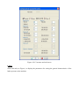
1
EasySTONE Manual EasySTONE Version 4.9 DDX S.r.l. Via G. Donizetti, 109/111 24030 Brembate di Sopra (Bergamo) - Italy TEL+39 035 621093 - FAX +39 035 333723 E-mail: [email protected] - web: www.ddxgroup.com Copyright 2003-2013 DDX S.r.l. All Rights Reserved This publication, or parts thereof, may not be reproduced in any form, by any means and for any purpose. This publication may not be distributed to third parties, nor its contents used or made known without prior express authorization by DDX S.r.l. Under no circumstance shall DDX S.r.l. be held liable to third parties for direct or indirect damages arising out of the use or lack of use of this publication or product. DDX S.r.l reserves the right to make changes or improvements to its products when deemed appropriate. This publication describes the state of the product at the time of publication and is in no way meant to describe any future products. The official version of the software on which this manual is based is Ver. 4.9. All information contained in this manual is subject to change without notice. All trademarks are the property of their respective owners. 2/10/2013 Table of Contents 1 Introduction 2 Installation 2.1 Hardware Requirements 2.2 Software Requirements 2.3 Installation Procedure 2.4 Entering the key codes 3 Interaction with EasySTONE 3.1 User Interface 3.2 Dialog Boxes 3.3 Function keys 3.4 Cursors 3.5 Selection Menu 3.5.1 Repeat Last Command 3.5.2 Attach to material 3.5.3 Selecting Entities 3.6 Plug-in 4 File Menu 4.1 New 4.2 Open 4.3 Save 4.4 Save As 4.5 Auto Run 4.6 Print 4.7 Print Worksheet 4.8 Digitize 4.9 Import 4.10 Export 4.11 Format Converter 4.12 STL Decimalizer 4.13 Properties 4.14 Notes 4.15 Groups 4.16 Setup 4.16.1 General 4.16.2 Import/Export 4.16.3 Machine 4.16.3.1 Select Current 4.16.3.2 Edit 4.16.3.3 Table 4.16.3.4 Transmission 4.16.3.5 Update Machine 4.16.3.6 Export Machine 4.16.4 Operations 4.16.5 Keyboard 4.16.6 Save position 4.16.7 Enable 4.17 Materials 4.18 SCL Script 4.18.1 Run Script 4.18.2 Edit Script 4.19 Exit 5 Display Menu 5.1 Zoom All 5.2 Zoom Window 5.3 Zoom Out 5.4 Zoom In 5.5 Dynamic Zoom 5.6 Zoom Selection 5.7 Pan 5.8 Mark End-points 5.9 Display 5.10 Top View 5.11 Front View 5.12 Back View 5.13 Left View 5.14 Right View 5.15 Aligned View 5.16 Iso View 5.17 Move Camera 5.18 Wireframe 5.19 Hidden Lines 5.20 Shading 5.21 Photorealistic View 6 Analysis Menu 6.1 Distance 6.2 Angle 6.3 Tangent Test 6.4 Analysis 6.5 Report 7 Database Menu 7.1 Tools 7.1.1 Tool Tree 7.1.2 Tool Parameter Buttons 7.1.3 Tool Parameters 7.1.4 Geometrical Parameters of Tools 7.1.5 Tool Magazine Buttons 7.2 Kits 7.2.1 Kit Tree 7.2.2 Kit Parameter Buttons 7.2.3 Tools used 7.2.4 Tools 7.2.5 Kit Database Buttons 7.3 Automatic CAM configuration 7.3.1 Configuration Buttons 7.3.2 General Configuration Property Tree 7.3.3 Association Buttons 7.3.4 Association Tree 7.3.5 Kit Tree 7.3.6 Buttons for Automatic CAM Interaction 7.4 Automatic DISP Configuration 7.4.1 Configuration Buttons 7.4.2 General Configuration Property Tree 7.4.3 Association Buttons 7.4.4 Association Tree 7.4.5 Shim Tree 7.4.6 Buttons for Automatic DISP Interaction 8 Mode Menu 8.1 Draw 8.2 Machining mode 8.3 Arrange mode 8.4 Generate mode 9 Design 9.1 Parts and Layers 9.1.1 Parts and Layers Tree 9.1.1.1 Layer Features 9.1.2 Parts and Layers Buttons 9.1.3 Current Layer Selection Area 9.2 Entity Colour 9.3 Snap Points 9.4 Commands 9.4.1 Point Coordinates 9.4.2 Angle Value 9.4.3 Calculator 9.5 Draw Graph 9.5.1 Line 2 points 9.5.2 Line Angle Length 9.5.3 Rectangle 9.5.4 Polygon 9.5.5 Arc by 3 points 9.5.6 Arc by Centre and 2 points 9.5.7 Arc P1 d P2 9.5.8 Arc Radius P1 P2 9.5.9 BiArc 9.5.10 Nurbs curve 9.5.11 Hole 9.5.12 Multiple Holes 9.5.13 Circle by 3 Points 9.5.14 Circle by Centre and Point 9.5.15 Circle by 2 Points 9.5.16 Text 9.5.17 Linear Dimensions 9.5.18 Angular Dimensions 9.5.19 Radial Dimensions 9.5.20 Import 9.5.21 Components 9.5.22 Interactive 9.5.23 Insert Solid 9.5.24 Ellipse 9.6 Build Graph 9.6.1 Frame 9.6.2 Shower Tray 9.6.3 Washbasin 9.6.4 Helix 9.6.5 Ruled 9.6.6 Loft 9.6.7 Net of curves 9.6.8 Surface of Revolution 9.6.9 Contoured plane 9.6.10 Swept 2 Rail 9.6.11 Fillet Surface 9.6.12 Link Surface 9.6.13 Trim Surfaces 9.6.14 Untrim Surfaces 9.6.15 Extend Surfaces 9.6.16 Surface Properties 9.6.17 Ribbon 9.6.18 Projection/ Development on surface 9.6.19 Curves from Surfaces 9.6.20 Surface intersection 9.6.21 Invert Normal 9.6.22 Edit Nurbs Control Points 9.7 Edit Graph 9.7.1 Move 9.7.2 Rotate 9.7.3 Scale 9.7.4 Mirror 9.7.5 Offset 9.7.6 Chamfer/Fillet 9.7.7 Trim/Extend 9.7.8 Stretch 9.7.9 Join 9.7.10 Split 9.7.11 Explode 9.7.12 Flip 9.7.13 Array Copy 9.7.14 Polar Copy 9.7.15 Enlarge 9.7.16 Move End-point 9.7.17 Delete 9.7.18 Modify Colour 9.7.19 Change Layer 9.7.20 Modify Entities 9.7.21 Align 9.7.22 Split into Sections 9.7.23 Modify Z 9.7.24 Interpolate 9.8 Process Graph 9.8.1 Move with tangent 9.8.2 Adjust Path 9.8.3 Make Tangent 9.8.4 Delete Duplicate Entities 9.8.5 Transform into Holes 9.8.6 Edit Label 9.8.7 Curve properties 9.8.8 Move Part 9.8.9 Scale Part 9.8.10 Mirror Part 9.8.11 Align Part 9.8.12 Minimize Overall Part Dimensions 9.9 Art Graph 9.9.1 Extrusion 9.9.2 Profile Extrusion 9.9.3 Profile Revolution 9.9.4 Circular Machining 9.9.5 Self-intersections 9.9.6 Art Union 9.9.7 Art Trim 9.9.8 Import Art 9.9.9 Export Art 10 Machining 10.1 Machining directory 10.1.1 Geometry 10.1.2 Machining Option Menu 10.1.3 Advanced Machining Properties 10.1.3.1 Machining Variation Menu 10.1.3.1.1 Routing Variations 10.1.3.1.2 Cutting Variations 10.1.3.1.3 Profiling Variations 10.1.3.1.4 Engraving Variations 10.1.3.1.5 Grooving Variations 10.1.3.1.6 Finishing Variations 10.1.3.1.7 5-axis Machining Variations 10.1.3.2 Tool Machining Simulation 10.1.3.2.1 Hole Management 10.1.3.2.2 Exclude surfaces 10.2 Kit 10.3 Command Area 10.3.1 Raw part 10.3.1.1 Rectangular 10.3.1.2 Offset 10.3.1.3 Lathe 10.3.1.4 From Surfaces 10.3.1.5 Generic lathe 10.4 Multiple Part Management 11 Kit and Machining Properties 11.1 Drilling 11.2 Routing 11.2.1 Driller prehole 11.2.2 Probing 11.3 Cutting 11.3.1 Cutting Repeat Operations 11.3.2 Probing 11.4 Pocketing 11.5 Profiling 11.5.1 Probing 11.6 Engraving 11.6.1 Probing 11.7 Grooving 11.8 Bevelling 11.8.1 Probing 11.9 Surface Roughing 11.9.1 Driller Roughing 11.9.2 Router Roughing &11.9.2.1 Prehole 11.9.3 Blade Roughing 11.9.3.1 Roughing with Normal Blade, Normal, Direct Step 11.9.3.2 Roughing with Horizontal Step Blade, Horizontal Step, Direct Step 11.9.3.3 Roughing with Horizontal Internal Blade, Horizontal Internal, Direct Step 11.10 Surface Finishing 11.10.1 Router Surface Finishing 11.10.1.1 Flowline Finishing 11.10.1.2 Pocketing Finishing 11.10.1.3 Constant Z Finishing 11.10.1.4 Scallop Finishing 11.10.1.5 Projection Finishing 11.10.2 Blade Surface Finishing 11.10.2.1 Normal and Normal Transversal Finishing 11.10.2.2 Horizontal Step and Horizontal Transversal Finishing 11.10.2.3 Horizontal Spiral Finishing 11.10.2.4 Horizontal Internal and Horizontal Transversal Internal Finishing 11.11 5-axis Finishing 11.11.1 5-axis Finishing with Router 11.11.1.1 Flowline 5-axis finishing 11.11.1.2 Pocketing 5-axis Finishing 11.11.1.3 Scallop 5-axis Finishing 11.11.1.4 Projection 5-axis Finishing 11.11.1.5 Development Type 5-axis Finishing 11.11.2 5-axis finishing with blade 11.11.3 Probing 11.12 Lathe Roughing 11.13 Lathe Finishing 11.13.1 Lathe Finishing with Router or Polishing Wheel 11.13.1.1 One Way Step, Zigzag and Spiral Step Lathe Finishing 11.13.1.2 Lengthwise One Way, Lengthwise Zigzag Lathe Finishing 11.13.1.3 Projection Lathe Finishing 11.13.1.4 Non-Interpolated Continuous Lathe Finishing 11.13.2 Lathe Finishing with Blade 11.13.2.1 One Way Step, Zigzag and Spiral Step Lathe Finishing 11.13.2.2 Lengthwise One Way, Lengthwise One Way Transversal, Lengthwise Zigzag, Lengthwise Zigzag Transversal Lathe Finishing 11.13.2.3 Non-Interpolated Continuous Lathe Finishing 11.14 5-axis Lathe Finishing 11.14.1 One Way Step, Zigzag and Spiral Step 5-axis Lathe Finishing 11.14.2 Lengthwise One Way, Lengthwise Zigzag Lathe Finishing 11.14.3 Projection Lathe Finishing 11.14.4 Non-Interpolated Continuous Lathe Finishing 11.15 Waterjet Cutting 11.16 5-axis Waterjet Cutting 11.17 Commands 11.18 Laser Projection 12 Arrangement 12.1 Shim 12.2 Optimization 12.3 Table Status 12.4 Move Parts 12.4.1 Fixed Point Configuration 12.5 Add Part 12.6 Delete Part 12.7 Copy part, Machining, Arrangement 12.8 Move Vacuums and Stops 12.9 Automatic Positioning 12.10 Reset Arrangement 12.11 Delete Missing Vacuums 12.12 Check Arrangement 12.13 Tool Setup 12.14 Use Lathe 12.15 Phase Management 12.16 Save Initial Arrangement 12.17 Import Initial Arrangement 12.18 Export Initial Arrangement 12.19 Delete Initial Arrangement 12.20 Automatic DISP 12.21 Arrangement Option Menu 13 Generation 13.1 NC Generation 13.2 Simulation 13.3 Times, Lengths and Costs Estimate 13.4 Transmission 13.5 Edit NC 13.6 Edit TLC 14 Help 14.1 Help 14.2 Tutorial 14.3 About the program 1 Introduction EasySTONE is a CAD/CAM software specifically designed for marble work. Developed in close cooperation with manufacturers and operators of the marble industry, it is extremely practical and intuitive to use. Easy and versatile, EasySTONE can be used immediately to design and follow a project through each and every stage: from design, to work, to machine setup, to the production of the final part. This manual describes and explains the configuration parameters, the options, the functions and the commands provided by the program. EasySTONE is available in different versions, each with different capabilities. For this reason, it is possible that some of the features described in this manual may not be available in the specific version you purchased. 2 Installation EasySTONE is available on DVD, or it may be downloaded from your personal customer area on the www.ddxgroup.it web site. Before starting the installation of EasySTONE, please check that your computer meets the minimum requirements necessary for the proper operation of the program. In order to increase the speed and productivity of EasySTONE, DDX suggests that you use a computer that meets the recommended requirements. 2.1 Hardware Requirements The minimum hardware requirements needed to run EasySTONE correctly are as follows: Processor: INTEL PENTIUM IV RAM: 512 MB Graphics: OpenGL compatible 32 Mb Free HD space: 1 Gb Mouse: (required) Monitor: 15" monitor with 1024x768 resolution Hardware: DVD-ROM reader To make the best use of the speed and productivity of EasySTONE, DDX recommends a system having at least the following specifications: Processor: INTEL Core i7 or equivalent RAM: 4 GB Graphics: nVidia GeForce GT 330M or higher Free HD space: 10 GB Mouse: required, with scroll wheel Monitor: 17" with 1280x1024 resolution Hardware: DVD-ROM reader 2.2 Software Requirements EasySTONE is compatible with the following operating systems: Microsoft Windows XP 32 bit with Service Pack 3 or higher or 64 bit with Service Pack 2 or higher. Microsoft Windows VISTA 32 and 64 bit with Service Pack 2. Microsoft Windows 7 32 and 64 bit. Microsoft Windows 8 32 and 64 bit. 2.3 Installation Procedure To install EasySTONE, run the Setup.exe program, available on the DVD you have received or in the files you have downloaded from the DDX Web site, and carefully follow the instructions displayed on screen. The main installation steps are: Enter the EasySTONE installation password provided by DDX with the program. Select the language that you would like to use during the installation. Agree to the EasySTONE user license. Select the folder in which you want to install EasySTONE. Select the EasySTONE path. Select the machines to be installed from the machines available. Start the installation. Towards the end of the installation procedure, a dialog box for the installation of the Smart Key drivers will be displayed. Install the Smart Key drivers to enable your product license dongle. 2.4 Entering the key codes When you purchase EasySTONE, DDX will provide you with a product license dongle that must be connected to the computer in order to use the program, the key codes required to activate it and a license file (*.dlic). When you first start EasySTONE, the program displays the Enter Key Code (Dongle Number) dialog box, in which you enter the first three segments of the key code. If you have purchased a network key to use multiple licenses, select the Network Key checkbox and enter the fourth part of the key code. Instead of manually entering the key code, you may also click the Browse button to open the Windows Browse dialog box where you can select and open the appropriate license file (*.dlic). This operation will fill the key code fields automatically. Figure 2.1: Entering the key code 3 Interaction with EasySTONE The graphic interface, the mouse and the keyboard of the computer provide full control of all the user functions of the EasySTONE software. 3.1 Graphic Interface EasySTONE's user interface (see Figure 3.1) is very easy to understand. It includes the following elements: 1. Drop-down Menu Bar (yellow box): The menu bar contains all the commands required to operate the program, organized by function. Commands and menu items displayed in black letters are available for use. Commands and menu items that are greyed out are currently inactive and are not available for use. When you move the cursor over the menu commands and menu items, the status bar on the left displays helpful explanatory notes to clarify the function of the item on which the cursor is currently located. The drop-down menu can be accessed also using the keyboard. To open a drop-down menu, press the key combination Alt + underlined letter (the letter that is underlined in the menu name that you want to open when you press Alt). 2. Toolbars (red box): This section contains several icons grouped in multiple toolbars. You can use these icons to quickly access the most common functions in the File, View, and Analysis drop-down menus. Toolbars may be docked to the top or left corners of the screen to form a single bar, or they may be undocked and float anywhere on the program screen. When you move the mouse cursor to an icon, a pop-up message displays the name of the corresponding function while the Status Bar on the left displays an explanatory note about the purpose of the item. 3. Mode bar (blue box): The icons in this section of the screen allow you to switch quickly from one operating mode to another. Four different operating modes are available. The same commands may also be found in the Mode menu. 4. Control panel (orange box): The Control panel includes all the commands, items, parameters, and options specific to the currently active mode, some of which are also included in the Machine drop-down menu. 5. Status Bar (purple box): This section of the screen shows information about the status of your application and general settings. From left to right, the Status Bar shows: the status of the program, the coordinates of the cursor (local coordinates and global coordinates), the unit of measurement (mm or inches), the current plane, the display mode of parts and layers, the current snap point and the machine used. Click the icon with the mouse to toggle the status. 6. Graphics Area: This area allows you to interact with a three-dimensional space in which you can design parts, select the parts to be machined and place them on the worktable, based on the current operating mode of the program. 7. Plug-in Area (pink box): If available, you can find the Beam and Nest functions in this section of the screen (see section 3.6). 8. Current Layer selection area (green box): The controls contained in this area allow you to quickly select a layer and make it the current active layer. This area displays all the planes of the project, except for generic planes. (See section 9.1.3). Figure 3.1: EasySTONE main window 3.2 Dialog Boxes Dialog boxes have multiple functions. They may contain commands or parameters, report errors or allow you to confirm an operation. The program uses several types of dialog boxes, including: Error Windows: this type of window informs the user that an error has occurred. Usually, this type of window also contains a brief description of the error, so that the user can correct it. To close the window, choose OK. Confirmation Dialog Windows: this type of window is displayed automatically by the program when you are performing operation that may require the deletion of some data. The program requests a confirmation before performing the requested operation to prevent accidental errors. In general, these windows contain three options: Yes, No and Cancel to confirm the execution of the operation, not execute the operation or cancel the operation respectively. Data Entry Windows: this type of window allows you to enter data. They also generally contain two buttons: OK and Cancel. Choose "OK" to close the window and save the changes. Choose "Cancel" to close the window without saving the changes, i.e. reverting all parameters to their previous values before you opened the window. 3.3 Function Keys The Function Keys present on all standard keyboards allow you to quickly access the most common functions in the File, View, and Analysis menus. The keyboard Function Keys perform the following operations: F1 = Open the program manual F2 = Zoom All F3 = Zoom Window F4 = Zoom Out F5 = Zoom In F6 = Pan F7 = Mark End-Points F8 = Top View F9 = Aligned View F10 = Iso View F11 = Distance F12 = Analysis 3.4 Cursors Moving the mouse cursor over each icon displays the name of the corresponding function. The mouse cursor may take different shapes, depending on the area in which it is located and the status of the program. 3.5 Selection Menu Using this menu (see Figure ), you can repeat the last command, assign materials to surfaces and select different entities. You can select entities without using this menu commands simply by selecting the desired entity in the graphics window using the left mouse button. This menu is displayed by right-clicking anywhere in the graphics window in Machine mode and in Draw mode, if no other command is active. 3.5.1 Repeat Last Command This menu item is available only when you open the menu in Draw mode, and repeats the last command executed. You can also use this command by pressing the Space bar. 3.5.2 Attach to material This menu item is available only when you open the menu in Draw mode and the View is set to Photorealistic. It allows you to draw a texture (image of a material) to surfaces and solids in the project. When you select this command, the program displays the Materials Configuration dialog box where you can select the material to be used for viewing the surfaces from a list. 3.5.3 Selecting Entities This group of commands allows you to select one or more entities from those present in the project. Figure 3.2: Selections Menu This set of commands includes: Select All: selects all the entities present in the current project. Deselect All: deselects all the entities present in the current project. Select Result: selects entities created or modified by the latest operation. Select Window: selects all the entities present in a specified area. After choosing this command, single-click with the left mouse button two opposite corners of the desired selection area to select all the entities that are fully or partially inside the selection rectangle. Select part: selects all the entities belonging to a same part by simply selecting one of its entities. This command selects the entities of the part that are not selected and deselects the entities that are already selected. You can also use this command by pressing the Tab key while selecting an entity. Select Layer: selects all the entities belonging to a same layer by simply selecting one of its entities. This command selects the entities of the layer that are not selected and deselects the entities that are already selected. You can also use this command by pressing the Shift key while selecting an entity. Select Continuous: this command selects all the entities that are located between two selected entities and that form a continuous geometric path. The starting entity must be selected before you execute the command. The direction of the selection is shown by the arrow displayed on the first selected entity. To toggle the direction, select the end-points of the entity with the mouse. Select Profile: this command selects all the entities that form a continuous path with the selected entity. This command selects the entities of the profile that are not selected and deselects the entities that are already selected. You can also use this command by pressing the Shift key while selecting an entity. Select Colour: this command selects all the entities with the same colour. Select Type: This command selects all the entities of the same type of the selected entity. Multiple selection: You can select multiple entities at the same time. Select the dialog box for choosing the entity when selecting any entity, even a single entity. After you have started the command and have selected a geometrical point, the program displays a window listing all the entities present at that point. The entities with a green dot are selected and the entities with the red dot are not selected. To toggle the selection status, select the name of the entity. You can also use this command by pressing the Alt key while selecting a point in the geometry. Invert Selection: This command allows you to toggle all selected and unselected entities of the project, i.e., it deselects selected entities and selects unselected entities. Figure: Multiple selection window 3.6 Plug-in Plug-ins are additional applications that add some functions to the program. The only plug-in currently available for EasyStone is DDXNest. By Nesting the efficient and waste-limiting operation of arranging irregular plane figures inside delimited areas without overlapping is meant. The DDXNest application provides a number of useful nesting functions, including interactive graphic nesting, nesting in cut-offs, specifying at the design stage which are the areas with defects and therefore cannot be used in the arrangements, nesting into irregularly shaped panels, nesting in multiple panels, automatic nesting of regular and irregular shapes. For details of all the functions and parameters available, please see the DDXNest User Manual. 4 File Menu This drop-down menu includes all the commands for working on the files of the project. 4.1 New This command creates a new project. If a project is already running and you decide to start a new project, the program displays a dialogue box (see Figure ) asking whether to save the changes to the current project or cancel the operation. The New command is not available (greyed-out) during Machining edit mode This command is available in the File menu, by pressing the Ctrl + N key combination or by clicking the 4.2 Open icon on the Toolbar. Figure 4.1: Open This command opens an existing project. When you select this command, the program displays the usual Open File dialog box from Windows (see Figure ) where you can specify path, name and extension of the desired project file. If the case, you can use the Preview option to display a preview of the selected project. If a project is already running and you decide to open another project, the program displays a dialogue box (see Figure ) asking whether to save the changes to the current project or cancel the operation (see Figure ).. The Open command is not available (greyed-out) during Machining edit mode. This command is available in the File menu, by pressing the Ctrl + O key combination, by dragging into the window of the program the project file you want to open, or by clicking the icon on the Toolbar. 4.3 Save Figure 4.2: Save This command saves the current project and updates its corresponding file. If the current project has never been saved before, the program displays the usual Save File dialog box (see Figure 4.2), where you specify path, name and extension of the project file to be saved. The Save command is not available (greyed-out) during Machining edit mode. This command is available in the File menu, by pressing the Ctrl + S key combination or by clicking the icon on the Toolbar. 4.4 Save As Figure 4.3: Save as This command saves the current project with another name. When you select this command, the program displays the usual Save File dialog box from Windows (see Figure 4.3), where you can specify path, name and extension of the project file to be saved. The Save As command is not available (greyed-out) during Machining edit mode. This command is available in the File menu, and by pressing the Ctrl + A key combination. 4.5 Auto Run This command generates and transmits to the machine the part programs for multiple projects. When you select this command, the program displays the Auto Run dialog box (see Figure ) that includes the following sections: 1. List of files to generate or transmit to the machine. 2. Machine to use. 3. Buttons for working on the file list. 4. Generation and transmission buttons. Figure 4.4: Auto Run List of files to generate This list allows you select or deselect the files to generate or transmit. The following four options are available for each file. CAM: if you select this option, the program will automatically estimate the specific machining operations to be applied to the project using the Automatic CAM function (Reference ). DISP: if you select this option, the program will automatically estimate the arrangement of the parts to be applied to the project using the Automatic DISP function (Reference ). Generate: if you select this option, the program will automatically generate the part program for project file (Reference ). Save: If you select this option, the program will save the part program for project file. If the file is deselected, i.e. if the checkbox next to the name of the file is not "ticked", no operation will be performed on that file and the file will be skipped. If you select the name of the four options available for the files in the list, you can deselect them for all the files with a single click and select them with a double-click (see Figure ). If errors occur during generation, these are listed with a brief description immediately next to the file that generated them. By right-clicking any point inside the list, you can display a popup menu containing the following items: Select All: selects all the files in the list. Deselect All: deselects all the files in the list. Machine: displays the Configure Machine dialog box where you can select the machine on which the geometry of the currently selected project file will be worked. Automatic CAM: displays the Open File dialog box from Windows where you can select the Automatic CAM configuration file (*.acd) to apply to the currently selected project file. Automatic DISP: displays the Open File dialog box from Windows where you can select the Automatic DISP configuration file (*.add) to apply to the currently selected project file. Machine to use Use this command to specify the machine you want to use to generate the machining operation. The following options are available: Use current machine: all the files are generated using the machine that is currently active. Use original machine for each project: each file is generated using the machine specified in the project itself. If you have specified a machine for one or more files using the Machine option of the popup menu displayed by right-clicking anywhere inside the list of files to generate, the program will ignore the Machine to use parameter for such file(s). Buttons for working on the file list Add folder: this command adds all the projects contained in a folder to the list of files to generate. When you select this command, the program displays the Browse folder dialog box, where you can specify the folder containing the project file to be added to the list. Add files: this command adds one or more projects to the list of files to generate. When you select this command, the program displays the Open File dialog box from Windows where you can select the project files to add to the list. To select more than one file, click on them while keeping pressed the Ctrl key. Delete: this command deletes the currently selected file from the list of files to generate. Generation and transmission buttons Generate: this command executes all the operations selected for each file and generates their part programs. Generate + Send: this command executes all the operations selected for each file, generates their part programs and sends them to the machine. 4.6 Print This command prints the current project. When you select this command, the program displays the Print dialog box (see Figure ) that includes the following sections: Printer. Print range. Preview controls. Print options. Print Preview. Figure 4.5: Print Printer In this section you can display and edit all the parameters and the properties of the printer you want to use. Name: here you can choose the name of the printer you want to use from the available printers. Properties: specifies the printer properties. Click this button to display the Properties dialog box for the selected printer where you can specify its options. The available properties vary depending on brand and model of the printer. Vector printing: select this option to enable vector printing on a plotter. Line thickness: this option is enabled only if the Vector printing option has been selected. You can use it to specify the thickness of the lines used to represent the geometry of the project in vector mode. Quality: specifies the print quality. The following options are available: High (32 bit). Normal (16 bit). Low (8 bit). Print range and preview controls In this area, you can check and edit the scaling factor settings. The following scaling options are available: Fit to a page: the image is scaled automatically according to the size of the page. Current view: prints the current view of the Graphics Area in a single page. To change the scaling factor, enter the desired value in the box next to Scale 1: and click Apply. The number of pages printed will vary depending on the scaling factor used. Scale drawing: the image is printed with the scaling factor specified with the Scale 1: option. The number of pages printed will vary depending on the scaling factor used. Scale 1: this option is available only if the Current view option or the Scale drawing option has been selected. You can use it to define the scaling factor for printing the geometry of the project. Apply: click this button to apply the settings specified for the scaling factor. From... To: these two boxes are available only if the Scale drawing option is selected. You can use it to specify the first and the last page to print. Preview buttons Use these buttons to navigate the pages displayed in the Print Preview panel. The four arrows allow you to navigate through the pages displayed in the Print Preview panel. You can also select the page displayed. The four arrows are active only if the Scale drawing option is selected. Print options This section allows you add additional information about the project on the printed pages. Number of pages: select this option to add a page number to the printed pages. Pages framing: select this option to add a frame to the printed pages. Info box: select this option to add an information box on the bottom right of the printed pages, including the description of the project and, if selected, a barcode with the description. Project page: select this checkbox to enable the Customer Data text boxes (see Figure ) and print a cover sheet including project description, designer and customer information. Print Preview This section of the page shows a preview of how the printed page will look using the current print settings. This command is available in the File menu, by pressing the Ctrl + P key combination or by clicking the icon on the Toolbar. 4.7 Print Worksheet This command prints the worksheet of the current project. When you select this command, the program generates the worksheet and displays it in a DDX Printer Server window. To print it, select the option Print in the File Menu. The worksheet includes: Title, Date and Time, Estimated time, Image of table with part, Tooling (position, name, compensation), Machining operations (operation, tool), Project data (title, object, author, machine, NC file, CNC), Part data (name, width, length, thickness, shim). The Print worksheet option will be available only after opening the Arrange mode or Generate mode for the current project. Figure 4.6: Print worksheet 4.8 Digitize This command opens the DDXDigi Digitizer. DDXDigi is a software application that connects a compatible external scanner or digitizer to EasySTONE in order to sample and digitize into the design environment contours or shapes from an existing physical object, a drawing, etc. For more information on using the DDXDigi software, please refer to its manual, which you can display by choosing Help from DDXDigi. 4.9 Import With this command you can open an existing project by importing it from an external format. When you select this command, the program displays the usual Import File dialog box from Windows (see Figure ), where you can specify path, name and extension of the project file to be imported. In this window you can display a preview of the project you want to open by selecting the Preview checkbox, and add the imported geometry to the current project by selecting the Add to current project option. If you select the Show import log checkbox, the program will display the Import Log window after importing the project (see Figure ), showing detailed information on the imported geometry. The program can import files with the following extensions: DXF Files, IGES Files, RHINO Files (*.3dm), STL Files, STEP Files, CAL Files, CSF Files (*.ent; *.hed; *.ens), HPGL Files, ISO Files (*.cnc), PNT Files (*.txt), LASER Files(*.mf), SMO Files (*.smo; *.egl; *.ewd; *.est; *.esc), IMAGE File (*.bmp; *.dib; *.jpg; *.pcx; *.tga). Figure 4.7: Import The Import command is only active in Draw mode. This command is available in the File menu, but you can also import an external project by dragging its project file into the window of the program. 4.10 Export You can use this function to export the geometries of the current project to a format compatible with other applications. When you select this command, the program displays the usual Export File dialog box from Windows (see Figure ), where you can specify path, name and extension of the project file to be exported. This window contains several options: You can display a preview of the project you want to export by selecting the Preview checkbox. By selecting the Selection option you can choose to export only the part of the project that you have selected before choosing Export. You can also select the unit of measurement used in the exported file. Finally, if you click on Favourite Folders, the program displays a drop-down menu with the list of your favourite folders, where you can set or remove the folders you use most often. If you click on Add, the program will display the Favourite folders dialog box where you can specify the name and the location of the folder you want to add. If you click on Delete, the program will display the Favourite folders dialog box where you can select the folder to remove. The program can export files with the following extensions: DXF Files, IGES Files, CAL Files, ENT Files, ENS Files, HED Files, HPGL Files, BMP Files, SMO Files. Figure 4.8: Export The Export command is only active in Draw mode. 4.11 Format Converter This command opens the file converter application for converting the format of some types of files. The converter allows you to convert files with the following extensions: *.dxf, *.iges, *.stl, *.cal, *.csf, *.iso, *.hpgl, *.pnt, *.smo, *.egl, * ewd e *.est to files with the following extensions: *.dxf, *.iges, *.egl, * ewd, *.est, *.ent, *.smo, *.cal or *.hpgl. When you select this command, the program displays the Converter Ver. (version number) dialog box (see Figure 4.9) that includes the following sections: List of files to convert: a list of the files to convert Conversion parameters: this section contains two options: Destination Directory: enter here the path name of the target folder location of the converted file. You can specify the path name also by pressing . When you select this command, the program displays the usual Open File dialog box from Windows (see Figure ), where you can specify the destination folder path name for the exported file. Destination Format: choose the desired conversion format from those available in the list. List of converted files: this list displays the converted files. The Results column will show a green dot if the conversion was successful or a red dot if the conversion failed. After selecting all the desired options, start the conversion by clicking on Convert ( ). Figure: Convert format The List of files to be converted contains also the following four commands: : use this command to add a file to the list of files to be converted. When you select this command, the program displays the usual Open File dialog box from Windows (see Figure ), where you can specify path, name and extension of the project file to open. : use this command to remove a file from the list of files to be converted. : use this command to move up the selected file by one row, thus increasing its priority. : use this command to move down the selected file by one row, thus decreasing its priority. 4.12 STL Decimalizer This function allows you to reduce the size of a file by approximating its surfaces and make it easier to work on a project. Figure: Decimalizer When you select this command, the program displays the Decimalizer Ver. (version number) dialog box (see Figure ) that includes the following sections: list of files to decimalize: this list contains the files to reduce in size. conversion parameters: this section contains two options: Destination Directory: enter here the path name of the target folder location of the decimalized file. You can specify the path name also by pressing [Edit Image] [Rename]. When you select this command, the program displays the usual Open File dialog box from Windows (see Figure ), where you can specify the destination folder path name for the decimalized file. Tolerance: enter here the level of approximation, i.e. the maximum error in mm allowable in the approximation of the geometry of the project. The lower the tolerance value, the higher is the quality of the part. List of decimalised files: this list displays the decimalised files. The Results column will show a green dot if the operation was successful or a red dot if the operation failed. After selecting all the desired options, start the conversion by clicking Convert ( ). The List of files to be converted contains also the following four commands: : use this command to add a file to the list of files to be converted. When you select this command, the program displays the usual Open File dialog box from Windows (see Figure ), where you can specify path, name and extension of the project file to open. : use this command to remove a file from the list of files to be converted. : use this command to move up the selected file by one row, thus increasing its priority. : use this command to move down the selected file by one row, thus decreasing its priority. 4.13 Properties Use this command to add additional information or a background to the current project. When you select this command, the program displays the Properties dialog box that includes the following sections: Title: use this box to enter the project title. Subject: use this box to enter the subject of the project. Author: use this box to enter the author of the project. Description: use this box to add a brief description to the project. Background: when this checkbox is selected, you can specify a background for the project. The following options are available: Location of the background image: use this box to specify the path of the image file that is to be used as background. You can specify the path name also by pressing the "..." button. Use this command to display the usual Open File dialog box from Windows (see Figure ), where you can specify path, name and extension of the image file you want to use as background. Image files with the following extensions may be used: JPeg Files (*.jpeg), Bitmap Files (*.bmp), DIB Files (*.dib), PCX Files (*.pcx), Targa Files (*.tga). X dimension: this value specifies the horizontal size of the background (X axis). Y dimension: this value specifies the vertical size of the background (Y axis). Position X: this value specifies the coordinate on the X axis of the lower left corner of the background with respect to the origin of the axes. Position Y: this value specifies the coordinate on the Y axis of the lower left corner of the background with respect to the origin of the axes. Keep ratio: select this option to preserve the aspect ratio of the image. When this option is selected, the program estimates the size of the background based on the value entered in Size X, disregarding the value of Size Y. Show as table background: select this option to use the image as the background of the table. Keep dimensions as default: select this option to keep the size of the background you have entered, even when the image is changed. Figure 4.11: Properties Select the camera icon to open the DDXPhoto application which allows you to use a photograph as the table background. For details, please see the DDXPhoto manual. 4.14 Notes You can enter comments about the current project. When you select this command, the program displays the Notes (see Figure 4.12) dialog box, containing a text editor for entering comments and notes. If you select the Show at startup checkbox, the notes will be opened automatically every time you start the program. Figure 4.12: Notes 4.15 Groups This function allows you to organise parts belonging to a same project into different groups that will be worked separately. The program does that by creating a specific Part Program (Reference ) for each Group. When you select this command, the program displays the Groups configuration dialog box that includes the following sections: Directory list of the groups: this list displays a tree structure of all the groups that have been created and the parts contained by each of them. List of parts: a list of all the parts contained by the project. Buttons for working on groups: the following buttons are available: Arrows: use the arrows to move parts from a list to another. You can also move parts by dragging them to the desired list. Add: use this command to create a new group. Rename: use this command to rename the currently selected group. Delete: use this command to delete the currently selected group. In Draw mode, all the groups are visible. However, in Machine mode, Arrange mode and Generate mode only one group may be active at any time. To choose a new active group, click on the toolbar icon (see Figure ) and select the current active group. The program displays a drop-down menu showing all the groups that have been created from which you may select the new active group. 4.16 Configuration You can configure some of the settings of the program. When you select this command, the program displays a submenu with the categories in which the settings are organised, including: General. Import/Export. Machine. Machining operations. Keyboard. Save position. Enable. Figure 4.13: Configure 4.16.1 General This command allows you to change the general settings of the program. When you select this command, the program displays the Program configuration window, which includes the following three tabs (see Figure ): Appearance General OpenGL Appearance Select this tab (see Figure 4.14) to display the options for customising the appearance of the program window. Figure: Program configuration - Appearance Toolbar: select this checkbox to display the Toolbar. Status Bar: select this checkbox to display the Status Bar. Mode Bar: select the checkbox to display the Mode Bar. If the checkbox is selected you can choose to display the Mode Bar on the left side or on the right side of the screen. Language: you can use this list box to specify the language of the program from the available languages. The language options are: Italian English French German Spanish Custom The Custom option allows you to add an additional language and, if chosen, will display the following three additional commands (see Figure ): M: click on this button to add a new translation of the messages of the program. When you select this command, the program displays the usual Open File Windows dialog box (see Figure ), where you can specify the folder and the name of the file that contains the new messages. The file containing the messages must be in the Messages File format (*.msg). H: click on this button to add a new translation of the manual of the program. When you select this command, the program displays the usual Open File Windows dialog box (see Figure ), where you can specify the folder and the name of the file that contains the new manual. The file containing the manual must be in the Help File format (*.chm, *hlp). T: click on this button to add a new translation of the tutorials of the program. When you select this command, the program displays the usual Open File Windows dialog box (see Figure ), where you can specify the folder and the name of the file that contains the new tutorials. The file containing the tutorials must be in the Help File format (*.chm, *hlp). Single instance of EasyStone: select this option to ensure that only one single instance of the program may be open at any one time. If this checkbox is not selected, you can open multiple instances of the program, but all additional instances after the first will not be able to modify any of the parameters of the Database Menu. General Select this tab (see Figure ) to display the options for customising the appearance of the program window. Figure: Program configuration - General This tab contains two sections: 1. Colour selection: this section contains a list for selecting the interface element whose colour you want to change, a colour button that shows the currently selected colour and allows you to choose a new colour, and the Default button for restoring the default colour set to all interface elements. 2. Grid options: this section includes a list box for choosing the type of grid used by the program. The options are: disabled, normal and dotted. The section also includes: Size: use this text box to specify the size of the squares of the grid, i.e. the distance between each two lines of the grid. No. of divisions: this option specifies the number of squares in which an un-enlarged grid square is divided when zooming. The section also includes: Reference: if this option is selected, the program will display in the Graphics Area the Cartesian reference indicating the 0 origin of the axes (see Figure ). Unit of measurement: use this option to specify the unit of measurement. The following units of measurement are available: mm: millimetres Inches LogLevel: use this option to specify the logging level, i.e. which information is to be recorded in the program log files. The following options are available: 0: no log. 1 (Log): the program saves a Log file, recording all the operations performed from when the program is started to when it is closed. 2 (Dbg): the program saves a Debug file, recording all the information about the parameters used for generating the part program. 4, 10 and 100: The program saves both a Log and a Debug file. Backup: use this option to specify how often the program should perform a backup of the current project and save it automatically. The following options are available: No backup. 1 minute. 2 minutes. 5 minutes. 10 minutes. 1 hour. 2 hours. The backup is used after an abnormal shutdown. When you restart the program after an abnormal shutdown, you will be asked if you want to recover the project that was open at the time of shutdown. OpenGL This tab (see Figure ) contains options for configuring the OpenGL settings of the graphics adapter. Colours: use this list box to specify the number of colours used and therefore the bit size of each pixel. Z Buffer: this value specifies the depth in pixels of the Z coordinate used for three-dimensional graphics. Generic Driver: select this checkbox to use a generic driver instead of the specific graphic driver installed on the computer. To implement the changes made in this page, you need to restart the program. Figure: Program configuration - OpenGL 4.16.2 Import/Export This command allows you to change settings for importing and exporting files. When you select this command, the program displays the Import/Export Configuration dialog box (see Figure ) that includes the following sections: 1. Extensions. 2. Iges. 3. ZMap Images. 4. 3dm. 5. Bitmap. 6. Laser. 7. Import Scripts. Figure: Import/Export Extensions The Extensions section allows you to associate one specific extension to each importable format for which multiple extensions are possible. The importable formats having multiple extensions are Hpgl, Iso, Pts, Laser. Iges Iges is a neutral data format for the exchange of data, graphics files and information between CAD systems. Trim type: this option specifies the type of trim performed. The following options are available: Default: performs trims as specified in the Iges file document, if present. Otherwise it is equivalent to the Choose UV parameter. Choose UV: trims surfaces. This method is almost always faster and more accurate. If that fails, the program falls back to trim in XYZ. Choose XYZ: performs trims in XYZ. This generic method is slower. If that fails, the program performs the trim in UV. Force UV: trims surfaces. Force XYZ: performs trims in XYZ. Art This type of file contains a special two-dimensional black-and-white image that is transformed into a surface during the import process. This particular image is created with specific equipment and indicates the depth of the carving on a gray scale, from white for minimum depth to black for maximum depth. Filter: this option allows you to specify the filter to be used with the imported file. The higher the value of the filter, the smoother the surface created. The following options are available: Custom: allows you to set a custom value. High: sets a high filter level (7). Medium: sets a medium filter level (5). Low: sets a low filter level (3). None: no filter is used. 3dm This type of file contains a geometry as surfaces and trims. Trim type: this option specifies the type of trim performed. The following options are available: Default: performs trims as shown in the Iges file document, if present. Otherwise it is equivalent to the Choose UV parameter. Choose UV: trims surfaces. This method is almost always faster and more accurate. If that fails, the program falls back to trim in XYZ. Choose XYZ: perform trims in XYZ. This generic method is slower. If that fails, the program performs the trim in UV. Step Step is a neutral data format that allows the exchange of data, graphics files and information between CAD systems. Trim type: This option specifies the type of trim performed. The following options are available: Default: performs trims as specified in the Iges file document, if present. Otherwise it is equivalent to the Choose UV parameter. Choose UV: trims surfaces. This method is almost always faster and more accurate. If that fails, the program falls back to trim in XYZ. Choose XYZ: performs trims in XYZ. This generic method is slower. If that fails, the program performs the trim in UV. Bitmap This type of image file contains a snapshot of the geometric area in its current state for export. Size: Use this option to specify the size of the exported image in pixels. Colours: Use this option to specify the number of colours for the exported image, and therefore the bit size of each pixel. Laser This type of file contains the points scanned by laser on the surface of the part, which is transformed into a surface during the import process. The part can be scanned either linearly on the worktable of the machine, or on a lathe. Lathe distance: this parameter is only used for lathe scanning and specifies the distance between the laser and the centre of the lathe. Lathe direction: this parameter is only used with lathe scanning and specifies the X or Y direction of the axis of rotation of the lathe. Filter: this option allows you to specify the filter to be used with the imported file. The higher the value of the filter, the smoother the surface created. The following options are available: Custom: sets a custom value. High: sets a high filter level (7). Medium: sets a medium filter level (5). Low: sets a low filter level (3). None: no filter is used. Import Scripts Pre-Import Script: this text box allows you specify the name of an SCL script to be executed before importing. You can specify the file name also by pressing the "..." button. When you select this command, the program displays the usual Open File dialog box (see Figure ), where you can specify the folder and the name of the file that contains the SCL script. Post-Import Script: this text box allows you specify the name of an SCL script to be executed after importing. You can specify the file name also by pressing the "..." button. When you select this command, the program displays the usual Open File dialog box (see Figure ), where you can specify the folder and the name of the file that contains the SCL script. 4.16.3 Machine This command allows you to modify the configuration settings for the operating machines. When you select this command, the program displays a submenu with the categories in which the settings are organized, including: Select current. Edit. Table. Transmission. Update Machine. Export Machine. Edit, Table and Transmission are password-protected, because incorrect changes made to these options may jeopardise the correct operation of the machine. These options should be modified only by experienced users or under direct supervision by a DDX engineer. 4.16.3.1 Select current This command allows you to select the active configuration of the machine. When you select this command, the program displays the Machine configuration dialog box where you can select the machine configuration that you want to make active from a list of available configurations. Figure 4.18: Machine configuration 4.16.3.2 Edit This command allows you to change some parameters in the configurations of the machines. It is password-protected. When you select this command, the program displays the Edit machine dialog box (see Figure ) that includes the following sections: Figure: Edit machine Machine: this parameter allows you to select the machine configuration from a list. All the other options present in the Edit machine dialog box refer to the selected machine configuration. Name: specifies the name of the machine. Type: this value is read-only and shows the number of work axes of the machine. Data: specifies the name of the file containing the specifications of the machine. You can specify the file name also by pressing the button. When you select this command, the program displays the usual Open File dialog box from Windows (see Figure ), where you can specify the folder and the name of the PPD file (*ppd). Additionally, by clicking on you can edit the post processor configuration parameters, which may vary from one machine to another. Arrangement: this section allows you to specify the placement of the shims. The section contains three fields: Type: this field specifies the shim arrangement type. The following options are available: Part program: when this option is selected, shim arrangement is performed semiautomatically. The arrangement is generated by the part program before the start of machining. The machine is fitted with a specific tool and moves to the positions where the operator is to place the part holders. Automatic: when this option is selected, the shims are positioned automatically by the machine. Laser: when this option is selected, shims s are positioned semi-automatically. The arrangement of the shims is indicated by laser projection of their boundaries, so that they can be positioned manually by the operator. Laser + automatic: with this option, the shims are positioned automatically by the machine and, additionally, the shim boundaries are indicated by laser. Laser projection (table): this option is available only when Type is set to Laser or Laser + Automatic, and it allows you to specify which entities are to be projected to the machine table. The following options are available: None: nothing is projected. Vacuums + references: the contours of vacuums and references are projected to their correct position. Vacuums only: the contours of vacuums are projected to their correct position. References only: the contours of references are projected to their correct position. Part: enables the Laser projection function from the Machine mode kit (Ref.), to project a selected path. Laser projection (vacuums): this option is available only when Type is set to Laser or Laser + Automatic, and it allows you to project a path at the vacuums level. The following options are available: None: nothing is projected. Part: enables the Laser projection function from the Machine mode kit (Ref.), to project a selected path. Probe: select this option to indicate the presence of a probe on the machine, enable the probe tool from the tool magazine and allow its use in the machining kits. Hourly cost: specify the depreciation cost per hour of the machine, so you can generate a more precise estimate of the machining costs. Hide: select this option to "hide" the machine, i.e. make it unavailable in the part work program. Read only: select this option to use the machine but prevent changes to the tool magazine and the kit magazine. Move: move the position of the machine on the computer. When you select this command, the program displays the Browse dialog box (see Figure 4.20) where you can select the destination folder for the machine files from the directory list of all the folders on your computer. Figure: Browse New: this option may or may not be present depending on the software license you have purchased. If present, it allows you to add new machine configurations. When you select this command, the program displays the Name dialog box (see Figure 4.21) where you can enter the name of the new configuration you are creating. You can also select the Existing machine checkbox to create the configuration of a machine for which you already have the relevant Machine Files (*.ppd). Figure 4.21: Name Dialog Box 4.16.3.3 Table This command allows you to change some parameters of the worktables in the configurations of the machines. It is password-protected. When you select this command, the program displays the Table Parameter Configuration window (see Figure 4.22), which includes the following four tabs (see Figure ): General Geometry Vacuums and references Lathes General Select this tab (see Figure ) to display the parameters for setting the general characteristics of the worktable. Figure 4.22: Table Parameter Configuration Table file: specify here the name of the file containing all the characteristics of the table of the active machine. You can specify the file name also by pressing the button. When you select this command, the program displays the usual Open File Windows dialog box (see Figure ), where you can specify the folder and the name of the desired file. Auxiliary file: this text box allows you to specify additional geometries to be placed on the table. You can specify the file name also by pressing the button. When you select this command, the program displays the usual Open File dialog box (see Figure ), where you can specify the folder and the name of the EST file (*.est) containing additional geometries. If the text box contains a file name already, click on to delete its location and enter a new one. Drilling File: use this box to enter the file name containing the positions of the holes on the table. You can specify the file name also by pressing . When you select this command, the program displays the usual Open File dialog box (see Figure ), where you can specify the folder and the name of the EST file (*.est) containing the design of the holes. If the text box contains a file name already, click on to delete its location and enter a new one. Number of tables: sse this box to enter the number of worktables on the current machine, up to maximum of three. Table position: the fields in this section allow you to define the location of the table and its origin. You can specify the following values: X position: this value specifies the coordinate on the X axis of the lower left corner of the worktable with respect to the machine zero point. Y position: this value specifies the coordinate on the Y axis of the lower left corner of the worktable with respect to the machine zero point. Z position: this value specifies the coordinate on the Z axis of the lower left corner of the worktable with respect to the machine zero point. Origin: this value specifies the table origin coordinates, matching the values specified on the machine. You need to enter the number assigned to the origin of the table and the corresponding Cartesian coordinates values relative to the machine zero point, separated by a comma. Figure 4.23: Origin definition Geometry Select this tab (see Figure ) to display the page for setting the geometric parameters of the worktable. Figure 4.24: Geometry This page contains four sections: 1. Dimensions: use this section to specify the dimensions of the worktable. It contains the following fields: X size: this value specifies the size of the worktable on the X axis. Y size: this value specifies the size of the worktable on the Y axis. Z size: this value specifies the size of the worktable on the Z axis. 2. Additional table: select this checkbox to enable an additional table located above the worktable. This section contains the following fields: X position: this value specifies the coordinate on the X axis of the lower left corner of the additional table with respect to the lower left corner of the worktable. Y position: this value specifies the coordinate on the Y axis of the lower left corner of the additional table with respect to the lower left corner of the worktable. Z Position: this value specifies the coordinate on the Z axis of the lower left corner of the upper surface of the additional table with respect to the lower left corner of the upper surface of the worktable. Based on the Z coordinate that is set, this value specifies the thickness of the additional table indirectly. X size: this value specifies the size of the additional table on the X axis. Y size: this value specifies the size of the additional table on the Y axis. Always enabled: if this option is selected, the additional table will always remain active, thus disabling the Enable additional table option (Ref.) in Arrange mode. Z position variable: if this option is selected, the Modify Z position of additional table option (Ref.) in Arrange mode will be enabled. "/> Figure 4.25: Additional Table Parameters No collisions: if this option is selected, any collision with the additional table will be ignored during the collision check. 3. Rotating table: select this option to enable a rotating table. The section contains the following field: Centre of rotation: enter the Cartesian coordinates of the centre of rotation of the rotating table with respect to the machine zero point. Separate each coordinate with a comma. 4. Colours: use this section to specify the colours of the worktable. It contains the following fields: Geometry: this option sets the colour of the geometry of the worktable. Background: this option sets the colour of the background of the worktable. Opacity: this option sets the opacity level of the background of the worktable. Additional table: this option is enabled only if the Additional table option has been selected. It allows you to specify the colour of the background of the additional table Opacity: this option is enabled only if the Additional table option has been selected. It allows you to specify the opacity level of the background of the additional table Vacuums and references Select this tab (see Figure 4.26) to display the options for specifying the number of shims available. The page contains the following seven sections, one for each type of shim: References A: this section contains up to two types of references. You can specify the number of references available for each type. Vices A: this section contains up to two types of vices. You can specify the number of vices available for each type. Vacuums A: this section contains up to four types of vacuums. You can specify the number of vacuums available for each type. Vacuums B: this section contains up to four types of vacuums. You can specify the number of vacuums available for each type. Vacuums C: this section contains up to four types of vacuums. You can specify the number of vacuums available for each type. Vacuums D: this section contains up to four types of vacuums. You can specify the number of vacuums available for each type. Vacuums + references: this section contains up to four types of vacuums + references. You can specify the number available for each type. Figure 4.26: Vacuums and references Lathes Select this tab (see Figure ) to display the parameters for setting the general characteristics of the lathes present on the machine. Figure 4.27: Lathe This page contains two sections: 1st Lathe: select this checkbox to enable the first lathe. The section contains the following parameters: Type: this parameter allows you to specify the desired type of lathe from the list of available lathes. The available types of lathe change based on the machine. X Position: this field allows you to set the X coordinate of the lathe zero point with respect to the machine zero point. Y Position: this field allows you to set the Y coordinate of the lathe zero point with respect to the machine zero point. Z Position: this field allows you to set the Z coordinate of the lathe zero point with respect to the machine zero point. Origin: this value specifies the lathe origin coordinates, matching the values specified on the machine. You need to enter the number assigned to the origin of the lathe and the corresponding Cartesian coordinates values relative to the lathe zero point, separated by a comma. : use this option to specify the direction of the lathe and the position of the motorized point (indicated by an arrow). Rotation: specifies the direction of rotation of the lathe during work. Part position: this field specifies the distance between the lathe zero point and the closest point of the axis of rotation of the part. 2nd Lathe: select this checkbox to enable the first lathe. The section contains the following parameters: Type: this parameter allows you to specify the desired type of lathe from the list of lathes available. The available types of lathe change based on the machine. X Position: this field allows you to set the X coordinate of the lathe zero point with respect to the machine zero point. Y Position: this field allows you to set the Y coordinate of the lathe zero point with respect to the machine zero point. Z Position: this field allows you to set the Z coordinate of the lathe zero point with respect to the machine zero point. Origin: this value specifies the lathe origin coordinates, matching the values specified on the machine. You need to enter the number assigned to the origin of the lathe and the corresponding Cartesian coordinates values relative to the lathe zero point, separated by a comma. : use this option to specify the direction of the lathe and the position of the motorized bit (indicated by an arrow). Rotation: specifies the direction of rotation of the lathe during work. Part position: this field specifies the distance between the lathe zero point and the closest point of the axis of rotation of the part. 4.16.3.4 Transmission This command allows you to change some part program transmission parameters in the configurations of the machines. It is password-protected. Figure: Transmission configuration When you select this command, the program displays the Transmission configuration dialog box (see Figure ) that includes the following sections: Machine: this list box allows you to select the machine configuration from a list. All the other options present in the Transmission configuration dialog box refer to the selected machine configuration. Iso extension: this text box allows you to specify the extension of the generated file that contains the part program. Generation: enter in this field the location on the computer where the part program is saved. You can specify the path name also by pressing . When you select this command, the program displays the Browse folder dialog box (see Figure ) where you can select the destination folder for the generated file from the directory list of all folders on your computer. Media: use this section to specify the transmission media for the file containing the part program. The following options are available: Network: the file is transmitted via a cabled or wireless network. Disk: the file is transferred via a mass storage device. Program: the file is transmitted by means of a special program. Disk: this section is available only if the part program transmission Media selected is Disk. It allows you to specify the destination drive for saving the file. Destination: enter here the destination path for the file containing the part program. You can specify the path name also by pressing . When you select this command, the program displays the Browse folder dialog box (see Figure ) where you can select the destination folder for the file from the directory list of all folders on your computer. Format: this field is used to specify the format of the name and the extension of the file sent. By default, the format of the name and the extension of the generated file containing the part program is "name.extension". You can however convert the name to uppercase by entering the letter U instead of the name, or to lowercase by entering L. If you do not enter anything, the name remains unchanged. To change the extension, enter the desired compatible extension after the dot. If you do not enter anything, the extension remains unchanged. On some machines, the file name must contain a maximum of eight characters, while the extension must contain a maximum of three characters. If the name is longer than eight characters, it will be truncated, leaving the first six and the last two characters only. Application Path: this field is used to specify the path of the application that will be used to transmit the file. You can specify the path name also by pressing the button. When you select this command, the program displays the File Open dialog box from Windows (see Figure ), where you can specify path, name and extension of the executable file. One of the following parameters may be appended to the path name of application: % file: indicates the name of the file in the command line. % destfile: indicates the destination file path at the end of the transmission. %origfile: indicates the source file path at the end of the command line. 4.16.3.5 Update Machine This command allows you to update the configuration of the active machine. When you select this command, the program displays the Update file type dialog box (see Figure ) where you can select the type of update required. The following options are available: Update from directory. Update from compressed file (zpak). A different dialog box will be displayed based on the type of update selected. Specifically, when updating from a directory, the program will display the Browse Folder dialog box (see Figure ) where you can select the folder containing the configuration of the machine from the directory list of all folders on your computer. When updating from a compressed zpak file, the program displays the usual Open File dialog box from Windows (see Figure ), where you can specify the location and the name of the desired Pack file (*.zpak). After selecting the directory or the zpak file containing the machine update, the program displays the Machine Update dialog box (see Figure ), where you can select the configuration files to update from all those contained in the update package. Figure 4.29: Update Machine In the Machine Update dialog box, the configuration files are displayed with different colours based on their status. The possible statuses are: Black: the updated file is identical to the one found in the current machine configuration. Blue: the updated file is not present in the current machine configuration. Red: the updated file is older than the one found in the current machine configuration. Green: the updated file is newer than the one found in the current machine configuration. 4.16.3.6 Export Machine This command allows you to export the configuration of the active machine When you select this command, the program displays the Export type dialog box (see Figure ) where you can select the type of export required. The following options are available: Export as directory. Export as compressed file (zpak) A different dialog box will be displayed based on the type of export selected. Specifically, when updating from a directory, the program will display the Browse Folder dialog box (see Figure ) where you can select the destination folder for the configuration of the machine from the directory list of all folders on your computer. When exporting as a compressed zpak file, the program displays the usual Save File dialog box from Windows (see Figure ), where you can specify the location and the name of the desired Pack file (*.zpak). 4.16.4 Machining This command allows you to define default values for some machining parameters. When you select this command, the program displays the Machining configuration dialog box (see Figure 4.30) containing the following sections: Tree structure of machining operations. Machining colour. Default kit values. General parameters. Generic parameters. Figure: Machining configuration Next to each field, the window also shows the explaining the meaning of the parameter. icon. Click on this icon to display a dialog box Figure: Approach distance Tree structure of machining operations This tree structure contains all the types of machining operations available for the current machine. You can use it to specify the type of operation configured by the options available in the Machining colour, Default kit values and General parameters sections. Machining colour This area contains a single option, named according to the type of machining operation currently selected in the tree structure. It is used to specify the colour of the machining path that is displayed in Machine mode. Default kit values This area contains the machining kit parameters for which you can set a default value that is used when you create a new kit. For detailed information on the meaning and function of each of these parameters, please refer to Chapter 11. General parameters This area contains the general machining parameters. The actual parameters shown vary depending on the type of operation currently selected in the tree structure, and include: Safety distance: this value specifies the distance from the part on the Z axis that the tool must reach before entering rapid movement mode. Approach distance: this value specifies the distance from the part on the Z axis that the tool must reach in rapid movement mode before starting work. Horizontal safety distance: this value specifies the distance from the part on the X and Y axes that the tool must reach before entering rapid movement mode. This parameter is not shown if the operation selected in the tree structure is a grooving operation, a lathe roughing operation, a lathe finishing operation, or a lathe 5-axis finishing operation. Default length of escape cuts: this parameter is shown only if a routing operation is selected in the tree structure and it allows you to specify the default length of the escape cuts. Non-interpolable radius: this parameter is shown only if a cutting operation is selected in the tree structure and it allows you to specify the minimum cutting radius of the blade. Multiple drilling: this parameter is shown only if a cutting operation is selected in the tree structure and it allows you to perform multiple drillings in a Cut Repeat operation. Raw part offset: this parameter is shown only if a cutting operation is selected in the tree structure. Z lead in pocketing: this parameter is shown only if a pocketing operation is selected in the tree structure. It is used to specify the tool entry position on the Z axis during the contouring stage. Z lead out pocketing: this parameter is shown only if a pocketing operation is selected in the tree structure. It is used to specify the tool exit position on the Z axis during the contouring stage. V groove start in Z: This parameter is shown only if a pocketing operation is selected in the tree structure. It is used to specify the distance in Z of the tool from the work surface where the V groove is to start. Generic parameters The field in this area is used for the configuration of generic machine parameters. When you select this option, the program displays the Generic parameters configuration dialog box (see Figure 4.32) containing the following parameters: Figure: Generic Parameters Configuration Safety Z above vices: this value specifies the minimum distance in Z that the tool must always keep when vices are present. Verify raw part dimension: this option enables checking the uncut size of the part. Raw part thickness: this value specifies the default thickness of the uncut part. Minimum raw part thickness: this value specifies the minimum thickness allowable for the uncut part. Default raw part offset: this value specifies the default raw part offset used by the program to calculate external cuts on the raw part border. Recalculate after raw part modification select this checkbox to recalculate the operations automatically after changes to the uncut part. Sink centre layer name: use this field to specify the default name of the layer whose centre is used as the starting point of a pocketing operation. This parameter is used for machining sinks and washbasins. Length of router unit vector: use this field to specify the length of the unit vectors displayed in Machine mode indicating the direction of the tool. Length of correction unit vector: use this field to specify the length of the unit vectors displayed in Machine mode indicating the direction of correction of the tool. Geometric tolerance: use this field to specify the tolerance used in the calculation of surfaces. Optimization tolerance: use this field to specify the tolerance used in cut optimization calculations. Lead-in adding radius (mm or %): use this field to enter a value to be added to the lead-in of tools. The program interprets this value as a distance in millimetres if it is greater than one, otherwise it will be considered as a percentage. XY origin type: this field specifies the position of the origin of the part on the XY plane. Generic XY origin: this field is only active when the XY origin type is set to Generic (table reference) and is used to specify the X and Y coordinates of the origin. Z origin type: this field specifies the position of the origin of the part on the Z axis. Generic Z origin: this field is only active when the Z origin type is set to Generic (table reference) and is used to specify the Z coordinate of the origin. 4.16.5 Keyboard Using this command, you can define a number of keyboard shortcuts to call the commands that you use most often. When you select this command, the program displays the Keyboard shortcuts dialog box where you can define and edit the associations between the key combinations and the selected commands. Figure: Configure keyboard The Keyboard shortcuts dialog box includes a list of the commands that you can associate to a shortcut and the controls for creating the association between commands and keyboard shortcuts. The dialog box shows a list of the commands that you can associate to a key combination shortcut. To add a command to the list, select it while the dialog box is open. To add a command for the four operation modes, you must select it in the drop-down menu. To associate a shortcut to a command, select the command in the list, select the desired shortcut key in the drop-down menu and click the Assign button. To add Ctrl or Shift key combinations, select the corresponding checkbox beforehand. To delete an association, select it in the function list and click the Delete button. 4.16.6 Save position The command allows you to save the size and position of the main window of the program. When the program is restarted, the main window is opened in the same location and of the same size that was saved. 4.16.7 Enable This command lets you enable additional functions in the program. When you purchase a package that provides additional functions, you are given a new key code. To enable the additional functions, enter the new key code in the Enter key code dialog box that appears when you select the Enable command. The Enable command is only active in Draw mode. Figure 4.34: Entering the key code 4.17 Materials This command lets you assign a texture reproducing a material to a solid. When you select this command, the program displays the Materials configuration dialog box (see Figure ) containing the following elements: Material list buttons. Directory list of available materials. Parameters specific to the selected material. Material list buttons New: use this button to create a new material. Delete: use this button to delete the currently selected material. Directory list of available materials This directory list contains all the materials available. Parameters specific to the selected material All the parameters in this section refer to material that is currently selected in the list. Name: specifies the name of the material. Image: specifies the path of the file containing the image of the material. Colour: allows you to define a colour filter to add to the material. Colour reflection: specifies the colour of the reflection. Transparency: allows you to specify the degree of transparency of the material as a value between 0 and 1. Type: this option sets the type of repetition of the material when it is smaller than the surface on which it is applied. Scale X: this value specifies the size of the image on the X axis. Scale Y: this value specifies the size of the image on the Y axis. 4.18 SCL Script Use this command to create and run SCL scripts. When you select this command, the program displays a submenu that contains the following commands: Run Script Edit Script Run Script Use this command to run an SCL script. When you select this command, the program displays the usual Open File dialog box (see Figure ), where you can specify the folder and the name of the file that contains the SCL script. 4.18.2 Edit Script Use this command to create an SCL script. When you select this command, the program displays the SCL Script dialog box (see Figure ) that includes the following elements: List of commands. Editor. Buttons. List of commands This list contains all the commands that you can include in an SCL script. Editor This section contains a text editor for displaying and editing the SCL script code. Double-click on a command to add it. After you have added a command, you need to replace the parameters in parentheses with the appropriate values. Buttons This section of the screen contains buttons for working with SCL scripts. Run all: click this button to run all the commands of the script. Run command: click this button to run all the commands contained in the currently selected line only. Reset: click this button to clear the SCL script from in the editor pane. Open: click this button to open an existing SCL script. When you select this command, the program displays the usual Open File dialog box (see Figure ), where you can specify the folder and the name of the file that contains the SCL script to open. Save: Use this command to save the SCL script you have created. When you select this command, the program displays the usual Save File dialog box (see Figure 1.1), where you can specify the folder and the name of the file that contains the SCL script to save. 4.19 Exit Use this command to exit the program. If an unsaved project is currently open, the program will display a dialog box (see Figure ) asking whether to save the changes to the current project or cancel the operation. 5 View Menu 5.1 Zoom all This command lets you resize the display of the current project to fit it entirely in the graphics window. This command is available in the View Menu, by pressing the F2 function key, by pressing the T key when the Display menu is open, or by clicking the ... Toolbar button. 5.2 5.2 Zoom Window This command lets you enlarge the selected portion of the graphics window. This command is available in the View Menu, by pressing the F3 function key, by pressing the F Display menu is open, or by selecting the area you want to enlarge with the left button of the mouse. 5.3 5.3 Zoom Out This command lets you shrink the display of the current project. Every time you select the command, the display is made one step smaller. This command is available in the View Menu, by pressing the Shift + Down key combination, by pressing the F4 function key, or by pressing the M key when the View menu is open. 5.4 5.4 Zoom In This command lets you enlarge the display of the project. Every time you select the command, the display is made one step larger. This command is available in the View Menu, by pressing the Shift + Up key combination, by pressing the F5 function key, or by pressing the P key when the View menu is open. 5.5 Dynamic Zoom This command lets you zoom in or zoom out the display area. To operate this command, press the left mouse button and move the mouse. The area around the position where you clicked will be enlarged. You can also obtain the same result by turning the mouse wheel. 5.6 5.6 Zoom Selection This command allows you to zoom in on the area that contains the selected entities. 5.7 Pan Use this command to pan the view of the project. To use the command, move the mouse while holding down the left mouse button. This command is available in the View Menu, by pressing the Up, Down, Right, or Left Arrow keys, by clicking the ... Toolbar icon, by pressing the F6 function key, by pressing the N key while the View menu is open, or by pressing the mouse wheel during the movement. 5.8 Mark End-points Use this command to highlight the end-points of all entities. Select it once to highlight the points and select it again to cancel the highlighting. You can also call this command by pressing the F7 function key, by pressing the E key when the View menu is open, or by clicking the ... Toolbar icon. 5.9 Show Select this command to open the Show Parts and Layers window. The main part tree may be broken down into individual layers. Figure 5.1: Show Parts and Layers You can choose which layers or parts to display by clicking on them. Selecting or deselecting a part affects all child layers. The window allows you also to display the raw part and the operations that have been set. Right-click anywhere inside the window to display a drop-down list with the following items: Show all: selects all parts and layers in the project. Show current layer: selects only the current layer. The currently selected layer is identified by a "lit" light bulb icon next to its name. If the layer is not selected, the light bulb icon remains grey. Confirm the operation by clicking OK, cancel all changes by clicking Cancel. You can call this command also by pressing the V key when the View menu is open. 5.10 Top View This command displays a top view of the project. You can call this command also by pressing the F8 function key or clicking the ... Toolbar icon. 5.11 Front View This command displays a front view of the project. You can call this command also by clicking the ... Toolbar icon. 5.12 Back View This command displays a back view of the project. You can call this command also by clicking the ... Toolbar icon. 5.13 Left View This command displays a left view of the project. You can call this command also by clicking the ... Toolbar icon. 5.14 Right View This command displays a right view of the project. You can call this command also by clicking the ... Toolbar icon. 5.15 Aligned View Aligned view shows the work plane aligned with the Z coordinate of the current construction plane. You can call this command also by pressing the F9 function key or clicking the ... Toolbar icon. 5.16 Isometric View This command shows the project with a 30° perspective in relation to the X, Y and Z axes of the plane. You can call this command also by pressing the F10 function key or clicking the ... Toolbar icon. 5.17 Move Camera This command lets you rotate the viewpoint of the project freely within the graphics area. To use the command, move the mouse while holding down the left mouse button. This command is available in the View Menu, by pressing the Ctrl+Up Arrow, Ctrl+Down Arrow, Ctrl+Right Arrow, or Ctrl+Left Arrow key combinations, or by pressing the Shift key or the Ctrl key while pressing the mouse wheel during the movement. Press Shift to move in relation to the selected point, press Ctrl to move in relation to the centre of the current view. 5.18 Wireframe This command shows all the contours and corners of all the parts that make up the project, even those that are hidden in the current view. 5.19 Hidden Lines This command shows only the contour lines of the project that are visible in the current view (front, side, etc.). 5.20 Shading This command displays all parts of the project with solid colours to better show surfaces and depths. 5.21 Photorealistic View This command displays the project using the photorealistic colours that had been previously set. 6 Analysis menu 6.1 Distance This command allows calculating the distance between two selected points. The calculated distance is displayed in the status bar on the left in the following form: distance, breakdown of the distance in the three coordinates (dx, dy, dz), angle of inclination in relation to the x-axis (C). The command can also be activated by pressing the F11 function key or the D key within the Analysis menu, or by selecting the command ... from the toolbar. 6.2 Angle This command allows calculating the angle between two selected objects. The calculated angle is displayed in the status bar on the left and in a small protractor in the graphics area bottom left, with parameters A1 and A2 that indicate the complementary angles. The command can also be activated by pressing the F11 function key or the D key within the Analysis menu, or by selecting the command ... from the toolbar. Figure 6.1: Angle 6.3 Tangency test This command allows analyzing the selected path. The Tangency test can only be performed if at least one geometric object has been selected. The test results are displayed both graphically and in the status bar. Graphically indicating: the points of tangency (green square). the tangency losses (red cross). the discontinuity points (blue square). The status bar on the left in the following form: tangents, loss of tangency and loss of continuity. The command can also be activated by pressing the F11 function key or the D key within the Analysis menu, or by selecting the command ... from the toolbar. Figure: Tangency test 6.4 Analysis This command allows displaying some characteristic data of the selected object. Once an object has been selected, the program displays a dialog box that shows the main characteristics. These may vary according to the type of object selected. The command can also be activated by pressing the F12 function key or the A key within the Analysis menu, or by selecting the command ... from the toolbar. Figure 6.3: Analysis 6.5 Report This command displays a dialog box (see Figure 6.4) with a list of characteristics of the object belonging to the project. Figure 6.4: Report Selecting an object in the graphics area automatically displays the data related to the said object; likewise, by selecting an object within the dialog box, the said object is highlighted in the project. The command can also be activated by pressing the F11 function key or the D key within the Analysis menu, or by selecting the command ... from the toolbar. 7 Database Menu This drop-down menu contains the commands to access the tool database, the kit database, the configurations database for the automatic CAM and the configurations database for the automatic DISP. Figure 7.1: Database menu 7.1 Tools This command allows to open the tool database, in which are present all tools defined by the user with related characteristics. Once this command has been activated, the program displays the Tool management dialogue box (see Figure 7.2), which comprises the following areas: 1. Directory list of available tools divided by type. 2. Buttons for interaction with the tool parameters. 3. List of parameters that characterize the selected tool. 4. Generic representation of the tool and definition of the geometries. 5. Buttons for interaction with the tool database. Figure 7.2: Tool management The command can be activated by selecting it in the Database menu and by pressing the U key within the same menu. 7.1.1 Tool tree This directory list contains all tools within the program, divided into the following types: driller. router. profiling tool. blade. engraving. bevelling. polishing wheel. probe. waterjet. 7.1.2 Tool parameter buttons This command allows creating new tools. Two different procedures can be followed to create a new tool: To create a tool identical to an existing one: Select an existing tool. Enable the New command. The program creates a new tool by copying all the characteristics of the selected tool. The new tool has the same name as that selected, accompanied by a number since each tool must have a unique name. To create a new tool without any parameter: Select the type of tool you wish to create. Activate the New command. The program creates a new tool belonging to the selected category devoid of any value. The new tool is named New accompanied by a number since each tool must have a unique name. This command allows deleting a tool in the database. The procedure is as follows: Select the tool to be deleted. Enable the Delete command. Confirm the deletion of the tool in the confirmation window that appears automatically This command allows confirming the changes made to the currently selected tool. 7.1.3 Tool parameters This area allows viewing and editing all parameters of each tool. To modify a tool, the procedure is as follows: Select the tool. Modify the desired parameters. Confirm your changes made to the tool by selecting the Confirm command. If, after modifying the current tool, another tool is selected or the Tool management dialogue box is closed before the changes made to the current tool are confirmed, the program will display a dialogue box (see Figure ) which asks whether to save the changes or not. Below is a diagram with the specific parameters of each type of machining operation and a description of each parameter. Diam Polis Bla Drill Rout ond ing ing h de Diam Polis Diam Polis ond ond h h Wate Polis rjet Prob ing profil profil cutt groov groo bevell bevel hing cutti ing ing ing ing ving ing ling ng X x x x x x x x x x x x x x x x x x x x x - - - - - - x - - - - - - - x x x x x x x x x x - x Tool cost x x x x x x x x x x - - Feed x x x - x x x x x x x - - x x x x x x x x x x - - - - - - - - - - - x - General Paramet x ers Water Absorpti on Compen sation Lead-in Feed Corners Feed Head - x - - x - - - - - - - x x x x - x x x x x x - x x - - x x - x - - - - x x x x x x x x x x - - - - - - x - - x - - - - x x x x x x x x x x x x - - x x - - - - - - - - - - - - - - - - - x - - x x x x x x x x x x - - Rotation x x x x x x x x x x - - - x x - - - - - - - - - x x x x x x x x x x - - Feed Lead-out Feed Max material Feasible metres Assembl y Name Number of profiles Preload Presetting Longitud inal S. Directio n Section - - x x - - - - - - - - - x x - x x - x - - x - - - x x - - - - - - - - - x - - - - - - - - - - Wear - - - x - - x - x x - - Wear L - - - x - - - - - x - - Overmat erial Section thickness Cutter type The tool parameters area (see Figure 7.3) comprises in turn the following areas: 1. General parameters. 2. Specific parameters. Figure 7.3: Parameters in the Tool management window General parameters The general parameters are uniformly present for all tool types. Position: This parameter allows positioning the tool in a tool holder of the machine and is used for the automatic tooling calculation. However, the user is free to choose the actual position of the tools in Arrange mode. Maximum rotation: This parameter defines the maximum rotation speed that the tool can reach measured in rpm. Draw: This parameter is only enabled for profiled tools and allows entering the path of the file containing the profile of the tool by typing it in the appropriate box or by selecting the command that displays the Windows Open File dialog box (see Figure ), in which to define the position, name and extension of the file containing the profile to enter. The element constructed from the profile entered will then be displayed in simulation. The imported drawing shows only half of the tool profile entered and the point 0.0 indicates the end-point of the rotation axis of the component (the drawing of the profiled tool section must be made in the fourth quadrant, i.e. in the lower right in relation to 0 of the reference plane). Figure 7.4: Profiling tool drawing Conic saw blade: This option is enabled for blade-type tools only and allows creating conical blades instead of flat. Assembly: This parameter defines the type of tool assembly on the machine. The types of assembly available vary depending on the tool that is being changed and the machine being used. The table below shows the possible types of assembly and a brief description: Group Name Description Vertical heads Vertical The tool is assembled vertically on the first normal head. Vertical 2 The tool is assembled vertically on the second normal head. Horizontal rotating transmission Horizontal rot 1 Horizontal rot 2 The tool is fitted on the first output of an angular transmission with two outputs; The tool is fitted on the second output of an angular transmission with two outputs; Special transmission Fixed angle 30° Fixed angle 45° Fixed angle 5° Fixed angle 15° The tool is fitted on an angular transmission with an output tilted at 30° The tool is fitted on an angular transmission with an output tilted at 45° The tool is fitted on an angular transmission with an output tilted at 5° The tool is fitted on an angular transmission with an output tilted at 15° 5 axes 5-axis head The tool is fitted on a 5-axis head 4-axes tilting The tool is fitted on a 4-axes transmission with turntable (tot. transmission 5 axes). 4-axes tilting The tool is fitted on a 4-axes transmission with turntable (tot. head 5 axes). Transmission on The tool is fitted on an angular transmission with a single 5-axis head Transmission (1) on 5-axis head output which in turn is tooled on a 5-axis head The tool is fitted on the first output of the angular transmission with four output which in turn is tooled on a 5axis head Transmission (2) The tool is fitted on the second output of the angular on 5-axis head transmission which in turn is tooled on a 5-axis head Transmission (3) The tool is fitted on the third output of the angular on 5-axis head transmission which in turn is tooled on a 5-axis head Transmission (4) The tool is fitted on the fourth output of the angular on 5-axis head transmission which in turn is tooled on a 5-axis head Bottom heads Bottom head Bottom head 2 The tool is fitted on the first head that allows to perform machining below the part The tool is fitted on the first head that allows to perform machining below the part Changing this parameter will also change the geometric representation and the parameters that are part of it. Specific parameters The specific parameters vary depending on the type of tool. Parameters shared by all tool types Name: This parameter defines the name by which the current tool is identified in the program. The program prevents two tools being created with the same name by displaying a hazard window (see Figure ) inasmuch there can be no uncertainty. Type of machining operation: This parameter allows defining the type of tool selected. Compensation: This parameter defines the compensation to be used during the machining operations of the current tool. Once the command has been activated, the program displays the Compensation selected dialog box that contains the compensation values (radius, length, ..) set in the numerical control table, which are used during the execution of the NC program. Only one compensation can be associated to each tool and can be chosen by selecting the desired parameter (see Figure ). If the compensation is set to 0, the correction is made by the software and not by the NC. (green= compensation free, red= compensation in use, yellow = current compensation). Water: This parameter defines the type of water supply during the machining operation. The water supply modes are: yes/both: both the internal and external water supply are enabled; internal: only the internal water is enabled; external: only the external water is enabled; intermittent: the water is activated at intervals defined by the machine logic; no: the water is not used. Parameter present in all machining operations except for probing and waterjet. Tool cost: This parameter defines the cost of the tool and is used to estimate the machining costs of the current project and the cost/metre of the tool. Parameter present in all machining operations except for probing and waterjet. Feasible metres: This parameter defines the average value of feasible cutting metres of the tool and is used to estimate the machining costs of the current project and the cost/metre of the tool. Parameter present in all machining operations except for probing and waterjet. Rotation: this parameter defines the standard rotation speed measured in revolutions per minute that the tool assumes during machining. Parameter present in all machining operations except for probing and waterjet. Direction: this parameter is only available for some types of machines and allows defining the tool rotation direction. Parameter present in all machining operations except for probing and waterjet. Specific parameters of each type of tool Drillers Figure 7.5: Tool Management - Drillers Max material: this parameter defines the maximum amount of material that the tool can remove during machining. If this parameter is set to 0 no checks are performed on it. Lead-in Feed: this parameter defines the entry speed of the tool into the part, expressed in mm/min or in/min. Feed: this parameter defines the speed of the tool during the machining of the part, expressed in mm/min or in/min. Lead-Out Feed: this parameter defines the exit speed of the tool from the part, expressed in mm/min or in/min. Router Figure 7.6: Tool Management - Router Router type: this parameter defines the shape of the tool and is important in the calculation of the machining operation because the software takes the shape of the selected tool into account. Max material: this parameter defines the maximum amount of material that the tool can remove during machining. If this parameter is set to 0 no checks are performed on it. Overmaterial: this parameter defines the amount of material, expressed in mm or in, voluntarily left in excess on the part in a radial direction relative to the tool (the length of the tool radius). Longitudinal overmaterial: this parameter defines the amount of material, expressed in mm or in, voluntarily left in excess on the part in a longitudinal direction relative to the tool (on the length of the tool). Head Feed: this parameter defines the speed of the tool during head machining, expressed in mm/min or in/min. Lead-in Feed: this parameter defines the entry speed of the tool into the part, expressed in mm/min or in/min. Feed: this parameter defines the speed of the tool during the machining of the part, expressed in mm/min or in/min. Lead-Out Feed: this parameter defines the exit speed of the tool from the part, expressed in mm/min or in/min. Profiling tool The profiling tools are divided into diamond profiling tool and polishing profiling tool. Figure 7.7: Diamond profiling tool Figure 7.8: Polishing profiling tool They share the following parameters: Number of profiles: this parameter defines the number of profiles that make up the tool. All other specific parameters refer to the individual profile currently selected, which can be changed by selecting the tabs of the different profiles in the lower left (see Figure 7.10). Figure 7.9: Profile number selection parameter Figure 7.10: Icons to switch from the parameters of one profile to another. Section: this parameter defines the shape of the tool section, i.e. the cutting section, choosing the standard ones from the appropriate drop-down menu or by selecting the command that displays the Section Manager dialog box (see Figure ), in which new sections can be defined, or existing ones deleted. Figure 7.11: Section Section thickness: this parameter defines the thickness of the section on the profile of the tool. This value is a form of security to prevent them from being mistakenly matched during the definition of the profiling kit. Lead-in Feed: this parameter defines the entry speed of the tool into the part, expressed in mm/min or in/min. Feed: this parameter defines the speed of the tool during the machining of the part, expressed in mm/min or in/min. Lead-out Feed: this parameter defines the exit speed of the tool from the part, expressed in mm/min or in/min. Diamond profiling tool Overmaterial: this parameter defines the amount of material, expressed in mm or in, voluntarily left in excess on the part in a radial direction relative to the tool (the length of the tool radius). Longitudinal overmaterial: this parameter defines the amount of material, expressed in mm or in, voluntarily left in excess on the part in a longitudinal direction relative to the tool (on the length of the tool). Polishing profiling tool Wear: this parameter defines the tool coefficient of radial wear and thereby allows the machine to compensate, with compensation, the radial wear of the tool during machining. Longitudinal wear: this parameter defines the tool coefficient of longitudinal wear and thereby allows the machine to compensate, with compensation, the longitudinal wear of the tool during machining. Blades Max material: this parameter defines the maximum amount of material that the tool can remove during machining. If this parameter is set to 0 no checks are performed on it. Overmaterial: this parameter defines the amount of material, expressed in mm or in, voluntarily left in excess on the part in a radial direction relative to the tool (the length of the tool radius). Absorption: this parameter defines the maximum effort sustained by the spindle during machining. This parameter must be enabled for some machines from the machine.ppd file. Head Feed: this parameter defines the speed of the tool during head machining, expressed in mm/min or in/min. Lead-in Feed: this parameter defines the entry speed of the tool into the part, expressed in mm/min or in/min. Feed: this parameter defines the speed of the tool during the machining of the part, expressed in mm/min or in/min Engraving The engraving tools are subdivided into diamond grooving and polish grooving. Figure 7.12: diamond grooving Figure 7.13: polish grooving They share the following parameters: Lead-in Feed: this parameter defines the entry speed of the tool into the part, expressed in mm/min or in/min. Feed: this parameter defines the speed of the tool during the machining of the part, expressed in mm/min or in/min Lead-out Feed: this parameter defines the exit speed of the tool from the part, expressed in mm/min or in/min. Diamond grooving Max material: this parameter defines the maximum amount of material that the tool can remove during machining. If this parameter is set to 0 no checks are performed on it. Overmaterial: this parameter defines the amount of material, expressed in mm or in, voluntarily left in excess on the part in a radial direction relative to the tool (the length of the tool radius). Polish grooving Wear: this parameter defines the tool coefficient of radial wear and thereby allows the machine to compensate, with compensation, the radial wear of the tool during machining Bevelling The bevelling tools are subdivided in diamond bevelling and polish bevelling. Figure 7.14: Diamond bevelling Figure 7.15: Polish bevelling They share the following parameters: Lead-in Feed: this parameter defines the entry speed of the tool into the part, expressed in mm/min or in/min. Feed: this parameter defines the speed of the tool during the machining of the part, expressed in mm/min or in/min Lead-out Feed: this parameter defines the exit speed of the tool from the part, expressed in mm/min or in/min. Diamond bevelling Max material: this parameter defines the maximum amount of material that the tool can remove during machining. If this parameter is set to 0 no checks are performed on it. Overmaterial: this parameter defines the amount of material, expressed in mm or in, voluntarily left in excess on the part in a radial direction relative to the tool (the length of the tool radius). Polish bevelling Wear: this parameter defines the tool coefficient of radial wear and thereby allows the machine to compensate, with compensation, the radial wear of the tool during machining Polishing Pre-load: this parameter for spring tools defines the additional depth the tool must make, after having performed the depth that positions the tool flush with the part, in order to load the spring that will compensate for the wear. Lead-in Feed: this parameter defines the entry speed of the tool into the part, expressed in mm/min or in/min Feed: this parameter defines the speed of the tool during the machining of the part, expressed in mm/min or in/min Lead-out Feed: this parameter defines the exit speed of the tool from the part, expressed in mm/min or in/min. Wear: this parameter defines the tool coefficient of radial wear and thereby allows the machine to compensate, with compensation, the radial wear of the tool during machining Longitudinal wear: this parameter defines the tool coefficient of longitudinal wear and thereby allows the machine to compensate, with compensation, the longitudinal wear of the tool during machining. Probing Probe type: this parameter defines the type of probe. Waterjet Overmaterial: this parameter defines the amount of material, expressed in mm or in, voluntarily left in excess on the part in a radial direction relative to the tool (the length of the tool radius). Corners Feed: this parameter defines the speed of the tool in the vicinity of edges along the machining path, expressed in mm/min or in/min. Feed: this parameter defines the speed of the tool during the machining of the part, expressed in mm/min or in/min. Lead-out Feed: this parameter defines the exit speed of the tool from the part, expressed in mm/min or in/min. 7.1.4 Tool geometry parameters This area allows viewing and editing all the geometrical parameters for each tool. This contains a generic graphic representation of the type of tool selected, the characteristics of which are described by parameters. The parameters vary depending on the type of tool selected. For the blade only, the working radius that is handled by the software must be considered positive if the tip of the blade is to the right of the spindle’s centre of rotation, negative if to the left. The Details command is also present for the blades. Once this command has been activated, the program displays a dialog box showing an enlargement of the blade profile to add additional geometrical data on the size of the cut profile. 7.1.5 Tool database buttons This command prints a sheet containing all the characteristics of a tool or a list of the tools in the database. The procedure to print the tool data sheets is as follows: Enable the Print command. Select the tools of which you wish to print the data sheet. The data sheet of all tools can be printed by selecting the All command. Select OK. The software automatically opens the DDX Printer Server with the tool data sheets to print. The tool data sheet contains: Tool name. Detail of the tool general parameters. Detail of the tool specific parameters. Detail of the tool geometric parameters. Figure 7.16: Tool data sheet The procedure to print the list of tools is as follows: Enable the Print command. Select the tools to be included in the list of tools to be printed. All tools can be entered in the list by selecting the All command. Select the Print tools list option. Select the OK command The software automatically opens the DDX Printer Server with the list of tools to print entered. The tools list contains: Type and name of the tool. Subtype of each tool. Position of each tool. Compensation of each tool. Length of each tool. Diameter of each tool. Max material of each tool. Figure 7.17: Tool list This command allows exiting the Tool management window confirming all changes made to the database. This command allows exiting the Tool management window without saving the changes made to the database even if already confirmed with the appropriate command. This command in the lower right of the Tool management window displays the Import and Export commands. If the Import and Export commands are already visible in the lower right, they can be hidden with . This command allows importing one or more tools from a file. Once the command has been activated, the program displays the Windows import file dialog box (see Figure ), which defines the location, the name and extension of the file to be imported. Once the file has been selected and opened, the program displays the Tool import dialog box (see Figure ) that contains a list of all the tools in the file from which to select those to be imported. More than one tool can be imported by pressing the Ctrl key while selecting them, or by using the All command to import all the tools in the file. This command allows exporting one or more tools in a file. Once the command has been activated, the program displays the Tool export dialog box (see Figure ) that contains a list of all the tools in the Tool database from which to select those to be exported. More than one tool can be exported by pressing the Ctrl key while selecting them, or by using the All command to export all the tools in the database. Once the selection of the tools has been confirmed, the program displays the Windows export file dialog box (see Figure 7.19), which defines the location, the name and extension of the file to be exported. Figure 7.18: Tool export Figure 7.19: Saving exported tools 7.2 Kits This command opens the kit database, which contains all the user-defined kits with related characteristics. The term kit means the set of tools and parameters used for a specific machining operation. One or more tools may be associated depending on the machining type of the kit. In particular, only one tool is allowed for the drilling, surface roughing, surface finishing, lathe roughing, lathe finishing, and waterjet kits. On the contrary, a list of one or more tools can be entered in the routing, cutting, profiling, pocketing, engraving, grooving, bevelling, 5-axis finishing kits. Once this command has been activated, the program displays the Machining library management dialog box (see Figure 7.20), which comprises the following areas: 1. Directory list of the kits grouped by machining type. 2. Buttons to interact with the parameters of the kit. 3. Tools and machining properties belonging to the currently selected kit. 4. Directory list of the tools grouped by type, compatible with the selected kit. 5. Buttons to interact with the kit database. Figure 7.20: Machining library management The command can be activated both from the Database menu and by pressing the K button within the Database menu. 7.2.1 Kit tree This directory list contains all kits in the program, divided into the types of machining available for the machine, including the following: drilling. routing. cutting. pocketing. profiling. engraving. grooving. bevelling. surface roughing. surface finishing. 5-axis finishing. lathe roughing. lathe finishing. 5-axis lathe finishing. waterjet. 5-axis waterjet. commands. By selecting the right button corresponding to the name of a kit, the program displays a drop-down menu that contains two commands that allow the user to rename and delete the selected kit. 7.2.2 Kit parameter buttons This button allows creating new kits. Two different procedures can be followed to create a new kit: To create a kit identical to an existing one: Select an already existing kit. Enable the New command. The software creates a new kit by copying all the characteristics of the selected tool. The new kit has the same name as the selected one accompanied by a number because each kit must have a unique name. To create a new kit without any parameters: Select the type of kit machining you want to create. Enable the New command. The software creates a new kit belonging to the selected category devoid of any value. The new kit has a New name accompanied by a number because each tool must have a unique name. This command allows deleting kits in the database. The procedure is as follows: Select the kit to delete. Enable the Delete command. Confirm the deletion of the kit in the confirmation window that appears automatically. This command allows renaming the kits in the database. The procedure is as follows: Select the kit to rename. Enable the Rename command. Enter the new name of the kit and press Enter. 7.2.3 Used tools This area allows viewing and editing all parameters of each kit. The parameters of a kit are: Name of the kit. Properties of the kit, divided into General and Advanced. Tools that make up the kit. The tools in the kit can be disabled by clearing the check mark next to the name of the tool, which changes the icon of the tool with an overlaid red X. The meaning and function of each parameter in the General and advanced properties and in the Tools are explained in detail in Chapter 11. Proceed as follows to edit a kit: Select the kit. Modify the desired parameters. Confirm the changes made to the kit by pressing the Enter key. Figure 7.21: General and advanced properties of the kits By selecting the name of a tool with the right mouse button, the program displays a menu with Properties as the sole command. Once the command has been activated, the program displays the Properties dialog box, which contains all the characteristics of the selected tool. 7.2.4 Tools This area allows viewing all tools divided by type that can be entered into the currently selected kit. Below is a list showing which tools can be used for each type of machining operation: Drilling consists of driller type tools. Routing consists of driller and router type tools. Cutting operations consists of blade, drill, router and waterjet type tools. Pocketing comprises router type tools and polishing and profiling tools. Profiling comprises probe type tools and profiling tools. Engraving comprises router, probe and profiling type tools. Grooving comprises grooving type tools. Bevelling comprises bevelling tools. Surface roughing comprises driller, router and blade type tools. Surface finishing comprises router, blade, polishing and profiling type tools. 5-axis finishing comprises router, blade, probe, polishing and profiling type tools. Lathe Roughing comprises blade type tools. Lathe Finishing comprises router and blade type tools. Two different procedures can be followed to add / remove a tool: Using drag'n'drop: Select a tool from the tools list and drag it to the used tools list or vice versa. Using the arrow commands: Select the tool to be moved. Enable the command or to add or remove the tool from the kit. By selecting the name of a tool with the right mouse button, the program displays a menu with Properties as the sole command. Once the command has been activated, the program displays the Properties dialog box, which contains all the characteristics of the selected tool. 7.2.5 Kit database buttons This command allows printing a sheet containing all of the characteristics and the list of tools belonging to a kit. The procedure to print the kit data sheets is as follows: Enable the Print command. Select the kit of which you want to print the data sheet. The data sheet of all kits can be printed by selecting the All command. Select Ok. The software automatically opens the DDX Printer Server with the kit data sheets to print. The kit data sheet contains: Name of the kit. Details of the kit properties. Details of the kit advanced properties. Details of the tools used and their condition (enabled, disabled, deleted). This command allows exiting the Machining library management window confirming all changes made to the database. This command allows you to exit from the Machining library management without saving the changes made to the database. This command in the lower right of the Machining library management window displays the Import and Export commands. However, if the Import and Export commands are already visible, they can be hidden with the command in the lower right. This command allows importing one or more kits from a file. Once the command has been activated, the program displays the Windows Import file dialog box (see Figure 7.22), which defines the location, the name and extension of the file to be imported. Once the file has been selected and opened, the program displays the Kit import dialog box (see Figure 7.23) that contains a list of all the kits in the file from which to select those to be imported. More than one kit can be imported by pressing the Ctrl key while selecting them, or by using the All command to import all the kits in the file. Figure 7.22: Import Figure 7.23: Selection of kit to import This command allows exporting one or more kits from a file. Once the command has been activated, the program displays the Kit export dialog box (see Figure 7.24), that contains a list of all the kits in the Kit database from which to select those to be exported. More than one kit can be exported by pressing the Ctrl key while selecting them, or by using the All command to export all the kits in the database. Once the selection of the kits has been confirmed, the program displays the Windows File export dialog box (7.25), in which to define the location, the name and extension of the file to be exported. Figure 7.24: Selection of kit to export Figure 7.25: Save as 7.3 Automatic CAM configuration This command displays the dialog box that contains the configurations database for the user-defined automatic CAM, each with its own parameters. A configuration for the automatic CAM is a set of associations that connect the machining kits to layers or labels. These associations are used by the program to automatically define the machining of the parts and thus speed up the production process. In particular, the automatic CAM is used on parts with a predetermined structure imported from other programs, or on parts created with the use of Components commands (Ref. ). Figure 7.26: Automatic CAM Configuration The Automatic CAM Configuration dialog box (see Figure 7.26) comprises the following areas: 1. Interaction buttons with the configurations. 2. Directory list of the general properties of the current configuration. 3. Interaction buttons with the associations. 4. Directory list of the associations. 5. Directory list of the kits. 6. Interaction buttons with the Automatic CAM Configuration dialog box. 7.3.1 Configuration buttons Drop-down menu to choose the configuration: This drop-down menu allows selecting the configuration amongst the existing ones to be made current. new: This command creates new configurations. The procedure is as follows: Enable the New command. Enter the name of the new configuration. Confirm the creation of the new configuration with Ok. delete: This command deletes the configurations present. The procedure is as follows: Select the one to be deleted from the list of configurations in the drop-down menu. Enable the Delete command. Confirm the deletion of the configuration with Yes. copy: This command creates a new configuration with the same parameters as an existing configuration. The procedure is as follows: Select the one to be copied from the list of configurations in the drop-down menu. Enable the Copy command. Enter the name of the copy, which must be different from that of the original. Confirm the creation of the new configuration, which has the parameters identical to those of the initial configuration, by selecting the OK command. 7.3.2 General configuration property tree This directory list contains the general machining parameters of the current configuration. Figure 7.27: General tree Groups This parameter allows applying the configuration to all parts in the project or just a part of them. The possible groups are: All parts: the configuration is applied to all parts of the current project. Parts of the current group: the configuration is applied to the current group only. Start This parameter allows entering an SCL script at the start of the configuration, which is executed before the machining operations are created. Part This group of parameters defines the operations to be performed before or after the machining of each part. The Part group of parameters is divided into: start: this parameter defines which operations to perform on the part before the machining calculation. The possible operations are: no operation: no operation is performed. reset: all machining operations applied to the part are cancelled. recalculate existing machining: all machining operations already present are recalculated. end: this parameter defines which operations to perform on the part after machining calculation. The possible operations are: no operation: no operation is performed. reset: all machining operations applied to the part are cancelled. script SCL start: this parameter allows entering a SCL script prior to the machining of the part. script SCL end: this parameter allows entering a SCL script after the machining of the part. Origin This group of parameters defines the position of the origin, which is necessary for the machining calculation. The Origin group of parameters is divided into: Origin XY: this parameter defines the position of the origin on the X and Y plane. The possible positions are: bottom-left. top-left. bottom-right. top-right. centre. generic. centre-left. centre-right. bottom-centre. top-centre. defined in project. Generic point: this parameter is only present if the XY Origin was set to generic and allows numerically defining the XY coordinates in which the origin is located. Origin Z: this parameter defines where the origin of the Z-axis is located. The possible positions are: above part centre of part above shim table generic (part ref.) generic (table ref.) defined in project. Z Generic: this parameter is only present if Origin Z was set to generic (ref.part) or generic (ref.table) and allows numerically defining coordinate Z where the origin is located in relation to the part or table. Raw part This group of parameter allows defining the type of raw part to be associated with each part. The Raw part group of parameters is divided into: Type: this parameter allows defining the type of raw part to associate to the part. The types of raw part are: Rectangular Offset External Offset Lathe. Minimum rectangular. Minimum lathe. From surfaces Generic from file Generic lathe From sheet. Defined in project. The following parameters will vary depending on the type of raw part and are: Rectangular This group of parameters allows defining all the characteristics of the rectangular raw part. Position: this parameter allows defining the position of the geometry drawn with respect to the rectangular raw part. The possible positions are: centre. top-left. top-right. bottom-left. bottom-right. top-centre. bottom-centre. centre-left. centre-right. X dimension: this parameter allows defining the length of the rectangular raw part on the X axis. Y dimension: this parameter allows defining the length of the rectangular raw part on the Y axis. X offset: this parameter allows defining the length of the movement of the rectangular raw part on the X axis in relation to the Position. Y offset: this parameter allows defining the length of the movement of the rectangular raw part on the Y axis in relation to the Position. Thickness: this parameter allows defining the thickness of the rectangular raw part. The automatic value can also be assigned to this parameter that allows the software to automatically set it based on the data of the part. Additional thickness: this parameter allows defining an additional thickness. Parameter which is used especially when the thickness parameter is set to automatic to define an additional thickness. Z position: this parameter allows defining the length of the raw part movement on the Z axis with respect to the upper surface of the geometry drawn. If the value is positive, the raw part is raised and lowered if negative. Offset This group of parameters allows defining all the characteristics of the raw part from a layer. Layer offset: this parameter allows defining the name of the layer that contains the profile of the raw part. Overmaterial: this parameter allows defining the thickness of the material to be added to the raw part in relation to the profile of the part. Thickness: this parameter allows defining the thickness of the rectangular raw part. The automatic value can also be assigned to this parameter that allows the software to automatically set it based on the data of the part. Additional thickness: this parameter allows defining an additional thickness. Parameter which is used especially when the thickness parameter is set to automatic to define an additional thickness Z position: this parameter allows defining the length of the raw part movement on the Z axis with respect to the upper surface of the geometry drawn. If the value is positive, the raw part is raised, and lowered if negative External Offset Similar to the offset but instead of specifying a layer, it uses the outermost contour of the raw part as the profile of the raw part. Overmaterial: this parameter allows defining the thickness of the material to be added to the raw part in relation to the profile of the part. Thickness: this parameter allows defining the thickness of the rectangular raw part. The automatic value can also be assigned to this parameter that allows the software to automatically set it based on the data of the part. Additional thickness: this parameter allows defining an additional thickness. Parameter which is used especially when the thickness parameter is set to automatic to define an additional thickness Z position: this parameter allows defining the length of the raw part movement on the Z axis with respect to the upper surface of the geometry drawn. If the value is positive, the raw part is raised, and lowered if negative Lathe This group of parameters allows defining all the characteristics of the raw part on the lathe. Position: this parameter allows defining the position of the geometry drawn with respect to the raw part. The possible positions are: centre. left. right. Generic point: this parameter allows defining the lengths of the movements of the raw part centre from the geometry drawn on axes X, Y and Z. Length: this parameter allows defining the length of the raw part. Side number: this parameter allows defining the number of sides of the raw part. Offset: this parameter allows defining the length of the raw part movement on the X axis compared to the geometry drawn. Diameter: this parameter allows defining the diameter of the raw part. The automatic value can also be assigned to this parameter that allows the software to automatically set it based on the data of the part. Rotation: this parameter allows defining the rotation angle of the raw part. Direction: this parameter allows defining the direction of the raw part in relation to the geometry drawn. The possible directions are: parallel to X: the raw part is positioned parallel to the X axis of the geometry drawn. parallel to Y: the raw part is positioned parallel to the Y axis of the geometry drawn. Section: this parameter allows defining the name of the layer that contains the profile of the raw part. Leave this parameter empty in order to use a profile defined by the previous parameters. Minimum rectangular This group of parameters allows defining all the characteristics of the minimum rectangular raw part. Thickness: this parameter allows defining the thickness of the rectangular raw part. The automatic value can also be assigned to this parameter that allows the software to automatically set it based on the data of the part. Additional thickness: this parameter allows defining an additional thickness. Parameter which is used especially when the thickness parameter is set to automatic to define an additional thickness. Z position: this parameter allows defining the length of the raw part movement on the Z axis with respect to the upper surface of the geometry drawn. If the value is positive, the raw part is raised, and lowered if negative. Overmaterial: this parameter allows defining the thickness of the material to be added to the raw part in relation to the profile of the part. Minimum lathe This group of parameters allows defining all the characteristics of minimum lathe raw part. Side number: this parameter allows defining the number of sides of the raw part. Rotation: this parameter allows defining the rotation angle of the raw part. Direction: this parameter allows defining the direction of the raw part in relation to the geometry drawn. The possible directions are: parallel to X: the raw part is positioned parallel to the X axis of the geometry drawn. parallel to Y: the raw part is positioned parallel to the Y axis of the geometry drawn. From surfaces This parameter allows defining the raw part from one or more surfaces. Layer surfaces: this parameter allows defining the name of the layer that contains the surface that defines the raw part. Generic, from file This parameter allows defining the raw part from a file. File: this parameter allows defining the name of the .vm file that contains the surface that defines the raw part. Generic lathe This parameter allows defining the raw part as a generic lathe. Layer surfaces: this parameter allows defining the name of the layer that contains the surface that defines the raw part. Generic point: this parameter allows defining the lengths of the movements of the raw part centre from the geometry drawn on axes X, Y and Z. Direction: this parameter allows defining the direction of the raw part in relation to the geometry drawn. The possible directions are: parallel to X: the raw part is positioned parallel to the X axis of the geometry drawn. parallel to Y: the raw part is positioned parallel to the Y axis of the geometry drawn. From sheet This group of parameters allows defining all the characteristics of the raw part from: Overmaterial: this parameter allows defining the thickness of the material to be added to the raw part compared to the profile of the part. Thickness: this parameter allows defining the thickness of the rectangular raw part. The automatic value can also be assigned to this parameter that allows the software to automatically set it based on the data of the part. Additional thickness: this parameter allows defining an additional thickness. Parameter which is used especially when the thickness parameter is set to automatic to define an additional thickness. Z position: this parameter allows defining the length of the raw part movement on the Z axis with respect to the upper surface of the geometry drawn. If the value is positive, the raw part is raised and lowered if negative Defined in project. This parameter allows keeping the raw part defined in the project without making any changes. End This parameter allows entering a SCL script at the end of configuration, which is executed after the creation of the machining operation. 7.3.3 Buttons for associations association type: this command allows defining the type of association to use. The types of associations are: Layer: the machining operations are associated with a layer based on the name. Label: the machining operations are associated with a label based on the name. new: This command allows creating new associations or commands. The procedure in order to create an association is as follows: Enable the New command. Enter the name of the new association or select it among those that are displayed by selecting the dots. Confirm the creation of the new association by selecting the OK command. Assign a machining kit, from those in the kits directory list (Reference 7.3.5), to the association created through the drag'n'drop operation. The procedure to create a command is as follows: Enable the New command. Select the Command option. Confirm the creation of the new association by selecting the OK command. Assign a machining kit, from those in the kit directory list (Reference 7.3.5), to the association created through the drag'n'drop operation. Modify: This command allows changing the associations present. The procedure is as follows: Select the association to be modified. Enable the Modify command. Change the name and write it in the space provided or choosing it from those present in the dots. Confirm the changes to the association by selecting the OK command Delete: this command allows deleting the associations present. The procedure is as follows: Select the association to delete from the directory list of associations. Enable the Delete command. Confirm the deletion of the association by selecting the Yes command. 7.3.4 Association directory list Figure 7.28: Associations section This directory list allows viewing and editing the parameters of each layer or label association and the machining kits of the current configuration. The parameters of an association are: Name of the layer or label. Tool that is part of the association. Properties of the association divided in General and Advanced. Figure 7.29: Association type Figure 7.30: Name of new application To create associations with several layers or several labels, one or more asterisks can be used in the name to replace any character. For example, the following uses are possible, assuming that there are layers or labels called one, two, three, four: u*: only the name one is associated. *u*: names two and four are associated. *u*o: only the name four is associated. General properties The values of the general properties may derive from the values set in the associated machining kit. Order: this parameter allows defining the type of machining order. The possible types are: automatic: the order is automatically defined by the software. locked: the machining order is respected. Single machining: this parameter allows defining whether to perform a single machining operation for multiple layers or make one for each. Closed path chaining: specifies the type of chaining to use in closed paths. The type of path can be defined by the kit, or follow a clockwise or counter-clockwise direction. Derived from kit. Counter-clockwise direction. Clockwise direction. Open path chaining: with the following parameter, the operator is able to define the machining start point and the direction to follow, i.e. the chaining to use is defined. Path type: Derived from kit. Centre of raw part to the left. Centre of raw part to the right. Counter-clockwise, closing with line. Clockwise, closing with line. Closer to the centre of the raw part. Further from the centre of the raw part. Closer to the exterior of the raw part. Further from the exterior of the raw part. Long side. Short side. Angle from outside. Angle from inside. Order in the database. Order in the database, inverted. Order by Minimum X local, increasing Y. Order by Minimum X local, decreasing Y. Order by Minimum Y local, increasing X. Order by Minimum Y local, decreasing X. Order by Maximum X local, increasing Y. Order by Maximum X local, decreasing Y. Order by Maximum Y local, increasing X. Order by Maximum Y local, decreasing X. Order by Minimum X global, increasing Y. Order by Minimum X global, decreasing Y. Order by Minimum Y global, increasing Y. Order by Minimum Y global, decreasing Y. Order by Maximum X global, increasing Y. Order by Maximum X global, decreasing Y. Order by Maximum Y global, increasing X. Order by Maximum Y global, decreasing X. Start closed paths: determines the machining starting point for closed paths. Type of path start: Derived from kit. Selection. Midpoint long side. Midpoint short side. Midpoint upper side. Midpoint lower side. Midpoint left side. Midpoint right side. Corner long side. Corner short side. Corner X min local. Corner X max local. Corner Y min local. Corner Y max local. Corner Z min local. Corner Z max local. Corner X min global. Corner X max global. Corner Y min global. Corner Y max global. Corner Z min global. Corner Z max global. Closer to the raw part centre. Further from the raw part centre. Closer to raw part exterior. Further from raw part exterior. Path order: if a machining operation involves multiple paths, this parameter allows choosing which path to start from. The order of the paths is activated by selecting more items to work with the same kit. At this point, in order to speed up the process, the paths can be ordered by following very precise rules so that, given an initial path, another closer path is subsequently machined rather than machining a path further away and then moving closer again and so on. This parameter is very important in order to optimize the machining speed. Type of order: Derived from kit. Selection. Inside to outside. Outside to inside. Horizontal, vertical, increasing Y. Horizontal, vertical, decreasing Y. Vertical, horizontal, increasing X. Vertical, horizontal, decreasing X. Minimum X, increasing Y. Minimum X, decreasing Y. Minimum X, optimize. Maximum X, increasing Y. Maximum X, decreasing Y. Maximum X, optimize. Minimum Y, increasing X. Minimum Y, decreasing X. Minimum Y, optimize. Maximum Y, increasing X. Maximum Y, decreasing X. Maximum Y, optimize. Minimum Z, optimize. Maximum Z, optimize. Advanced properties Condition: this parameter allows defining the conditions that must occur in order to ensure the association of the machining operation to the part (see Figure 7.31). Figure 7.31: Conditions To enter up to three conditions, the procedure is as follows: Enable the Condition command. The Condition dialog box automatically opens. Select the drop-down menu to set one or more conditions. Confirm the conditions set by selecting the Ok command. To add more conditions, the procedure is as follows: Enable the Condition command. The Condition dialog box automatically opens. Select the Advanced option. Write the conditions in the text line using the parameter codes (see Figure (table)). Confirm the conditions set by selecting the Ok command The codes that can be used with the Advanced option active are shown in the following table. PARAMETER ADVANCED CODE Current group CURRGROUP Current part CURRPIECE Raw part type TYPE Thickness THICK Raw part position POS Pos Z POSZ Dim X DIMX Dim Y DIMY Ofs X OFFSETX Ofs Y OFFSETY Overmaterial OVERMAT Origin XYTYPE Origin Z ZTYPE X min raw part BOXXMIN X max raw part BOXXMAX Y min raw part BOXYMIN Y max raw part BOXYMAX Z min raw part BOXZMIN Z max raw part BOXZMAX The operands that can be used with the Advanced option active are shown in the following table. OPERANDS ADVANCED OPERANDS Equal == Higher > Lower < Different != Higher Equal >= Lower Equal <= And AND Or OR Filter: This parameter allows defining filters, i.e. allows defining the types of articles to which to apply the association (see Figure 7.32). Figure 7.32: Filter The procedure to create a filter is as follows: Enable the Filter command. The Filter dialogue box opens automatically. Select the drop-down menu to set up the filter. Select the drop-down menu to set up any conditions related to the filter. Confirm the filter and the conditions set by selecting the Ok command. The available filters are: Lines only. Arcs only. Lines and Arcs only. Circles only. Holes only. Text only. Nurbs curves only. Nurbs surfaces and polymesh only. Nurbs surfaces only. Polymesh only. All types. Variation: this parameter allows making changes to the machining operations. To apply the desired change, a label must initially be associated to the article to be machined, subsequently selecting variations within the automatic CAM dialogue box. Figure 7.33: Automatic CAM machining changes The Variation dialogue box (see Figure 7.33) is subdivided into: Label: this parameter allows selecting the name of the label to which to apply the machining changes. Variation type: this parameter allows defining the type of change to be applied to the machining operation, i.e. the machining parameters of which the value must be changed. The possible variations are: none: no variation is applied. feed: changes the feed in the machining section associated with the label in question; initial extension: elongates the tool lead-in. final extension: elongates the tool lead-out. stop: enters a machine stop at the end of the selected entity. command: enters a direct command after the machining of the selected entity. initial sinking: defines how much the tool must sink into raw part in the initial part of the entity associated with the label in question. final sinking: defines how much the tool must sink into raw part in the final part of the entity associated with the label in question. initial width: defines how wide the machining should be in the initial part of the entity associated with the label in question. final width: defines how wide the machining should be in the final part of the entity associated with the label in question. Value: this parameter defines the value of the machining parameter to change. SCL Script start: this parameter allows entering a SCL script prior to the application of the machining operation to the part. (see Figure 7:34) Figure 7.34: SCL Script SCL Script end: this parameter allows entering a SCL script after the application of the machining operation to the part. 7.3.5 Kit tree This directory list contains all kits in the program, divided into the following machining types available for the machine: drilling. routing. cutting. pocketing. profiling. engraving. grooving. bevelling. surface roughing. surface finishing. 5-axis finishing. lathe roughing. lathe finishing. 5-axis lathe finishing. waterjet. 5-axis waterjet. commands. 7.3.6 Automatic CAM interaction Buttons Verification: This command is available only if the Automatic CAM Configuration window is opened from the machining mode, and allows starting the automatic CAM calculation. Ok: This command allows quitting the Automatic CAM Configuration window confirming all changes made to the configurations. Cancel: This command allows quitting from the Automatic CAM Configuration window without saving the changes to the configurationsImport: This command allows importing a configuration from a file for the automatic CAM. Once the command has been enabled, the program displays the Windows file import dialog box (see Figure ), which defines the location, the name and extension of the file to be imported. Once the file has been selected and opened, the program displays the Name dialog box (see Figure ) in which to rename the configuration to import. Esporta: This command allows exporting a configuration for the automatic CAM from a file. Once the command has been enabled, the program displays the Windows file export dialog box (see Figure ), which defines the location, the name and extension of the file to be exported. 7.4 Automatic DISP configuration This command displays the dialog box that contains the database of configurations for the userdefined automatic DISP, each with its own parameters. An automatic DISP configuration is a set of associations that link the shims to the parts. These associations are used by the program to automatically define the arrangement of the parts and thus to speed up the production process. In particular, the automatic DISP is used on parts with a predetermined structure and imported from other programs, or parts created using the Components command (Ref. ). Figure 7.35: Automatic DISP configuration The Automatic DISP configuration dialogue box (see Figure ) comprises the following areas: 1. Configuration interaction buttons. 2. Directory list of the current configuration general properties. 3. Association interaction buttons. 4. Association directory list. 5. Shim directory list. 6. Automatic DISP configuration dialogue box interaction buttons. 7.4.1 Configuration buttons configuration selection drop-down menu: This drop-down menu allows selecting the configuration amongst the existing ones to make current. new: New configurations can be created with this command. The procedure is as follows: Enable the New command. Enter the name of the new configuration. The name must be different from that of any other configuration, since each tool must have a unique name. Confirm the new configuration by selecting the Ok command. delete: This command allows deleting the configurations present. The procedure is as follows: Select the configuration to be deleted from the list in the drop down menu. Enable the Delete command. Confirm the deletion of the configuration by selecting the Yes command. copy: This command allows to create a new configuration with the same parameters of an existing configuration. The procedure is as follows: Select the configuration to be copied from the list in the drop down menu. Enable the Copy command. Enter the name of the copy, which must be different from that of the original, since each tool must have a unique name. Confirm the new configuration, which has all the parameters identical to those of the initial configuration, by selecting the Ok command. 7.4.2 Configuration general property tree This directory list contains the current configuration general parameters. Groups This parameter allows applying the configuration to all the parts in the project or just a part of them. The possible groups are: all parts: the configuration is applied to all parts of the current project. parts of the current group: the configuration is applied to the current grouping only. Start This group of parameters allows defining the operations to be performed at the start of configuration. The group of Start parameters is subdivided in: operation: this parameter allows defining which operations to perform on the part prior to the arrangement calculation. The possible operations are: no operation: no operation is performed. reset: the current arrangement is deleted. initial arrangement: this parameter allows to set an initial arrangement already defined in a file (of type Initial Arr File (*.disp)). Once the parameter has been selected, the program displays the of Windows open file dialog box (see Figure ), which defines the location, the name and extension of the file that defines the original arrangement. To delete the set initial arrangement file, select it with the right button of the mouse and select Delete. SCL script: this parameter allows entering a SCL script at the start of configuration, which is executed before the arrangement. Parameters This group of parameters allows defining: optimization: this parameter is only used if there are several parts in the project and defines the type of optimization to be applied to the machining operation. Possible optimizations are: part: the machine performs all the machining operations with all the necessary tools on a part before moving to the next part. project: the machine performs all the machining operations with the same tool on all parts before passing the next tool, thus saving tool change time. active table: this parameter is used only if it allows defining which the currently active table is. Interference check This parameter allows defining the type of interference check the program must perform. The Interference Check group of parameters is subdivided into: Perform check: this parameter allows enabling or disabling the interference check. Minimum distance: this parameter defines the minimum distance below which the program must give the danger of collision warning. Controls: this parameter allows defining the parts (part, shim, vacuums, references, vices, etc.) between which to perform the interference check. The possible controls are: vacuums only: a control is made that there are no interferences between the vacuums used in the current project. shim: a control is made that there are no interferences between the shims used in the current project. shims and table: a control is made that there are no interferences between the shims and the worktable used in the current project. shims, table and other parts: a control is made that there are no interferences between the shims, worktable and the parts used in the current project. shims and other parts: a control is made that there are no interferences between the shims and parts used in the current project. vacuums and table only: a control is made that there are no interferences between the vacuums and the worktable used in the current project. vacuums, table and other parts only: a control is made that there are no interferences between the vacuums, the worktable and the parts used in the current project. vacuums and other parts only: a control is made that there are no interferences between the vacuums and the parts used in the current project. Setup This parameter allows defining the parameters of the setup to be used during machining. The group of Setup parameters is subdivided into: Type: this parameter allows defining the type of setup. The types of setup are: automatic: the program places each tool in the tool holder defined in the tool magazine. from file: this parameter allows setting a setup already defined in a file (type Set Up File (*.stf)). predefined: the setup defined in Arrange mode is saved without any changes made. File: this parameter is active only if the type of setup is set as from file and allows defining the setup file name. End This group of parameters allows defining the operations to be performed at the end of configuration. The End group of parameters is subdivided into: operation: this parameter allows defining which operations to perform on the part after the arrangement calculation. The possible operations are: no operation: no operation is performed. reset: the current arrangement is deleted. delete unused vacuums: deletes all unused vacuums. SCL script: this parameter allows entering a SCL script at the end of configuration, which is executed after the arrangement. 7.4.3 Association buttons new shim: This command allows creating new associations with shims. The procedure to create an association is as follows: Enable the New shim command. Assign a shim, from those in the directory list of shims (See 7.4.5), to the association created through the drag'n'drop operation. new part: This command allows creating new associations with the parts. The procedure to create an association is as follows: Enable the New part command. Assign a part to the association created by setting its parameters (See 7.4.4). delete: This command allows deleting the associations present. The procedure is as follows: Select the one to delete from the directory list of associations. Enable the Delete command. Confirm the deletion of the association by selecting the Yes command. 7.4.4 Association tree This directory list contains the associations between shims and the parts that allow the program to automatically calculate the arrangement. Each shim association contains a particular shim and the parameters that define its position, and each part contains parameters that allow identifying the part and defining the position. Shim Class: this parameter allows defining the identification number/name of the shim entered in the association. Position: this parameter allows defining the coordinates of the shim compared to the reference position. Reference position: this group of parameters defines the reference position of the shim coordinates. The choices are: table, bottom left corner. table, bottom right corner. table, top left corner. table, top right corner. table, centre. part, bottom left corner. part, bottom right corner. part, top left corner. part, top right corner. part, centre. The group of parameters is subdivided into: Part type: this parameter is used only if the Part reference parameter is set to one of the options that use the part as a reference, and allows choosing how to identify the part to be used as a reference. The choices are: By name. By ID. By order in the Database. Part identification: this parameter is used only if the Part type parameter is set by name, or by ID, and allows entering the identification name or number of the part to be used as a reference. Angle: this parameter allows defining the angle of rotation with which to position the shim on the worktable. Advanced: this group of parameters contains additional parameters to define the shim. Condition: this parameter allows defining the conditions that must occur in order to perform the association of the machining operation to the part (see Figure 7.31). Figure 7.31: Conditions The procedure is as follows to enter up to three conditions: Enable the Condition command. The Condition dialogue box automatically opens. Select the drop-down menu to set up one or more conditions. Confirm the conditions set by selecting the Ok command. The procedure is as follows to add more conditions: Enable the Condition command. The Condition dialogue box automatically opens. Select the Advanced option. Write the conditions in the text line using the parameter codes (see Figure (table)). Confirm the conditions set by selecting the Ok command. The codes that can be used with the Advanced option active are indicated in the following table. PARAMETER ADVANCED CODE Current Group CURRGROUP Number of Parts NUMPIECES The operands that can be used with the Advanced option are indicated in the following table. OPERANDS ADVANCED OPERANDS Equal == Higher > Lower < Different != Higher Equal >= Lower Equal <= And AND Or OR SCL Script start: this parameter allows entering a SCL script before the machine has positioned the shim on the worktable. SCL Script end: this parameter allows entering a SCL script after the machine has positioned the shim on the worktable. Part Part type: this parameter allows choosing how to identify the part entered in the association. The choices are: By name. By ID. By order in the Database. Part identification: this parameter is used only if the Part type parameter is set by name, or by ID, and allows entering the identification name or number of the part to be used as a reference. Positioning type: this group of parameters allows defining the type of part positioning. The possible choices are: dimensions. bottom left alignment. top left alignment. bottom right alignment. top right alignment. fixed points. The group of parameters is subdivided into: Position: this parameter is used only if the Positioning type parameter is set to positions, and allows defining the barycentre of the part by entering the coordinates. Referenced to the origin: this option, if enabled, allows positioning the origin of the part in the point defined by the Position parameter, otherwise it positions in the bottom left corner of the part. Angle: this parameter allows defining the angle of rotation with which to position the part on the worktable. Fixed point: this parameter is used only if the Positioning type parameter is set to fixed points, and allows determining the fixed point in which to position the part. Shim: this parameter allows determining the thickness of the shim. Advanced: the conditions are defined within the advanced parameter to perform the automatic arrangement, the SCL script start and SCL script end. Condition: This parameter allows defining the conditions that must occur in order to make the association of the machining operation to the part (see Figure 7.31). Figure 7.31: Conditions The procedure is as follows to enter up to three conditions: Enable the Condition command. The Condition dialogue box automatically opens. Select the drop-down menu to set up one or more conditions. Confirm the conditions set by selecting the Ok command. The procedure is as follows to add more conditions: Enable the Condition command. The Condition dialogue box automatically opens. Select the Advanced option. Write the conditions in the text line using the parameter codes (see Figure (table)). Confirm the conditions set by selecting the Ok command. The codes that can be used with the Advanced option active are indicated in the following table. ADVANCED PARAMETER CODE Current Group CURRGROUP Number of Parts NUMPIECES The operands that can be used with the Advanced option are indicated in the following table. OPERANDS ADVANCED OPERANDS Equal == Higher > lower < Different != Higher Equal >= Lower Equal <= And AND Or OR SCL Script start: this parameter allows entering a SCL script before the machine has positioned the shim on the worktable. SCL Script end: this parameter allows entering a SCL script after the machine has positioned the shim on the worktable. 7.4.5 Shim tree This directory list contains all the shims present in the program, divided into the types of shims available for the machine, amongst the following: references. vacuums. vices. vacuums with references. 7.4.6 Automatic DISP interaction buttons Verification: This command is available only if the Automatic DISP Configuration window is opened from the machine mode, and allows starting the calculation of the automatic DISP. Ok: This command allows quitting the Automatic DISP Configuration window confirming all changes made to the configurations. Cancel: This command allows quitting the Automatic DISP Configuration window without saving the changes made to the configurations. Import: This command allows importing a configuration from a file for the automatic DISP. Once the command has been activated the program displays the Windows import file dialogue box (see Figure ), which define the location, the name and extension of the file to be imported. Once the file has been selected and opened, the program displays the Name dialog box (see Figure ) in which to rename the configuration to import. Export: This command allows exporting a configuration in a file for the automatic DISP. Once the command has been activated the program displays the Windows export file dialog box (see Figure ), which defines the location, the name and extension of the file to be exported. 8 Mode menu 8.1 Draw mode Figure 8.1: Draw mode The Draw mode groups the commands for geometry definition relating to the product to manufacture. The commands are available both from the Draw, Build, Edit and Process drop-down menus and from the control panel located beside the interface (see Figure 8.1). The Draw mode will be elaborated in chapter no. 9 Design. 8.2 Machine mode Figure 8.2: Machine mode The machine mode comprises the commands for the definition of raw parts, paths and tools relating to the machining of the drawn geometry. The commands are available both from the Work drop-down menu and from the control panel located beside the interface (see Figure 8.2). The Machine mode will be elaborated in chapter no. 10 Machining. 8.3 Arrange mode Figure 8.3: Machine mode The Arrange mode groups the commands for defining the arrangement of the raw part and related shims on the worktable. The commands are available both from the Arrange drop-down menu and from the control panel located beside the interface (see Figure 8.3). The Arrange mode will be elaborated in chapter no. 12 Arrangement. 8.4 Generate mode Figure 8.4: Generate mode The Generate mode comprises the commands for the generation of the part machining program and for the related file transfer to the machine, the running and view of simulation, the calculation of duration and length of machining operations. The commands are available both from the Generate drop-down menu and from the control panel located beside the interface (see Figure 8.4). The Generate mode will be elaborated in chapter no. 13 Generation. 9 Design The draw mode deals with the realization and editing of the geometry of the parts to machine. The draw mode control panel is subdivided into five overlapping pages which contain all draw commands, i.e.: Draw. Build. Edit. Process. Art. The commands can be activated from the control panel and from the Draw, Build, Edit, Process, Art menus available in the drop-down menu bar. 9.1 Parts and Layers This command allows selecting the currently active part and layer. Each project is made up of one or more parts, and each part is made up of one or more layers. Each layer has its own features, for instance its own Cartesian system and origin point; it is made up of entities (lines, arcs, surfaces, etc.) which take on its reference plane. By selecting the command (downward arrow icon), the program displays the Part and Layer Management Dialog (see Figure ), which is made up of the following areas: 1. Directory list of parts and layers present in the current project. 2. Buttons for part and layer management. 9.1.1 Directory list of parts and layers This directory list contains the parts involved in the current project along with their layers and related features for each of them. To view the layers of one part and related features select icon . To hide them select icon instead (see Figure ). The properties of the layer can be modified by selecting them with a double click. It is possible to hide a part or a layer except for the current one by selecting the yellow bulb alongside, which turns grey. To reactivate it just reselect the grey bulb, which turns yellow again. By right-clicking on a part or a layer the program will show a menu which enables cutting, copying or pasting it. 9.1.1.1 Layer features Reference plane This parameter allows defining the reference plane of the layer among those available, i.e.: Top. Bottom. Front. Back. Left. Right. Vertical. Generic. Recess right. Recess left. Recess front. Recess back. By three-points. From current view. It is also possible to select a surface or the side of a solid as a reference plane in the graphics area; then the program sets the plane type and related parameters automatically. Origin This parameter allows defining the position of the origin point of the reference plane with respect to the project origin. It is possible to edit this parameter both by entering the values of the origin point coordinates and by selecting it from the graphics area. X angle This parameter is available only for the down front, down back or generic reference planes, and allows defining the width of the angle by which the plane rotates with respect to the X axis of the global reference. Y angle This parameter is available only for the recess right, recess left or generic reference planes, and allows defining the width of the angle by which the plane rotates with respect to the Y axis of the global reference. Z angle This parameter is available only for the vertical or generic reference planes, and allows defining the width of the angle by which the plane rotates with respect to the Z axis of the global reference. 3-point-plane This parameter allows defining the reference plane by giving three points. The first point defines the reference plane origin, the second point defines the X axis and the third point defines the Y axis. 9.1.2 Part and layer buttons new P: this command allows adding a new part to the current project. new L: this command allows adding a new part layer to the currently selected part. erase: this command allows erasing the part or the currently selected layer. edit: this command allows editing the name and the features of the parts and the layers. 9.1.3 Current layer selection area In this area the commands are available for making the layers current in the graphics area directly. The commands allow activating the layers that are defined by reference planes such as top, front, back, right, left and vertical. In case more layers have the same reference plane it is possible to view the list by rightclicking on the reference plane and then selecting the one to activate. 9.2 Entity colour This command allows selecting the colour of the newly-created entities. After selecting the command, the program displays the window for colour selection, where it is possible to select the desired colour or select the Other command, which allows displaying the Windows dialog box for choosing the colour (see Figure ), in order to have a wider choice. Figure 9.1: Selection colours 9.3 Snap points In this menu all commands that allow using the snap points are provided. Snap ponts are points belonging to geometric entities or to the plane; they allow the user to choose the selectable point, thus making drawing easier and accuracy higher. It is possible to view the menu Snap points in two ways: by right-clicking on any point of the graphics area in draw mode, if no other command is active. by left-clicking on the currently active snap point on the status bar. Figure 9.2: Snap point menu The snap points are as follows: End-point: acquires the end-point nearest to the selection point of the selected entity. Midpoint: acquires the midpoint of the selected entity. Centre: exactly identifies the central point of the selected circle or arc. In case of lines the midpoint is identified. Near point: acquires the entity point that is nearest to the selection point. Quadrant: allows acquiring the circumference points along the axes which define the quadrants (the point nearest to the selection point is selected. Figure: Circle quadrants Sketch: selects the plane point perfectly coinciding with the cursor position. Grid: acquires the plane point coinciding with the grid point nearest to the selection. Intersection: acquires the intersection point between two entities. To select it: 1. press the mouse left button when the cursor is on the first entity; 2. release the mouse left button when the cursor is on the second entity (while moving the mouse the left button must be held down). Layer Centre: acquires the barycentre of the layer the selected entity belongs to. Tangent: acquires the point tangent to the selected entity. Perpendicular: acquires the point perpendicular to the selected entity. Automatic: allows acquiring the point in automatic mode according to the previously set up configuration. Automatic configuration: adds or deletes one snap point from the list of active snap points during the Automatic point selection mode. To set up the automatic operation two different procedures may be followed: select Automatic configuration and the desired snap point among those present in the Configuration menu beside the Snap point menu. select Configure: a dialog box will open (see Figure 9.4) inside which it is possible to select the snap points of interest. To add the type of snap point activate the flag beside the desired snap point and confirm by pressing Ok. Figure: Configure The choice can also be carried out by selecting the letter corresponding to the desired snap point. It is possible to establish on which plane to create the drawing by selecting Draw in XY or Draw in XYZ; this latter operation allows entering also the Z coordinate. Figure: Snap point menu 9.4 Commands The parameters required by the system may be entered via keyboard or acquired from the graphics area with the mouse. The parameters that are supplied manually must be confirmed by selecting or by pressing the key Enter of the keyboard, while the parameters supplied with the mouse are confirmed automatically. To avoid this automatic confirmation hold down key Ctrl of the keyboard during mouse acquisition. The confirmation of the last parameter runs the command. To cancel a command press button or key Esc of the keyboard. When the snap points are active the command Cancel is also available from the menu which appears when the mouse right key is pressed in the graphics area. 9.4.1 Point coordinates During the drawing phase it is possible to provide, in addition to X and Y coordinates, also the Z coordinate of points by right-clicking in the graphics area and selecting Draw in XYZ or Draw in XY. The points may be provided both in Cartesian coordinates and in polar coordinates: Cartesian coordinates: enter values X, Y and Z separated by a comma. It is possible to omit one of the coordinates by keeping the separating comma (e.g.:,,100); in that case the value of the omitted component is equivalent to the value of the latest entered point. Polar coordinates: enter module (Length) and argument (Angle) separated by symbol "<" (e.g. 100<45) in order. In Draw in XYZ mode the user may add the Z value preceded by a comma (e.g. 100<45,50). Both representations may be expressed absolutely or relatively: in the latter case the coordinates must be preceded by symbol "@". The Cartesian coordinates of points may be acquired as snap points by left-clicking in the graphics area. The points can always be entered through the calculator, which appears when the command (see Figure ) next to the text box is clicked on. 9.4.2 Angle value The value of an angle can be entered manually via keyboard or calculator. Besides, the program allows entering the value of an angle by obtaining it from another entity: in this case select the entity where data are to be obtained from by simultaneously holding down the Shift key. Alternatively it is possible to press button which is located next to the command Calculator and choose one of the eight preset angles (see Figure 9.6). Figure 9.6: Preset angles 9.4.3 Calculator Some data required by the drawing functions, for instance the line by two points, can be entered via the calculator. The calculator is activated by the key next to the data input box (see Figure 9.7) and appears only when the function is enabled. The Visual function shows the result of the operation carried out without closing the calculator. When the definition of the coordinates of one point is required, the X, Y and Z commands of the calculator provide the result of the operation in the x, y or z field respectively. The values attributed to the X,Y and Z can be called up by selecting MX, MY, MZ and used for addition, multiplication, etc. operations. The Z and MZ functions are available only in Draw in XYZ mode. When the definition of a single datum is required, the X, Y, Z, MX, MY and MZ commands are replaced by the Enter, M and < commands, which have the function of entering the result of the latest operation, calling up the value present in the data box and erasing them respectively. Figure: Point input calculator 9.5 Draw Graph 9.5.1 2-point line This command allows creating segments that are defined by the start point and the final point. After activating the command, the procedure is as follows: Select the start point. Select the final point. The software allows creating another segment having as a start point the end-point of the previous segment automatically. To create a new segment: Select the new final point. To interrupt the creation of segments: Select cancel or press the Esc. key. Figure: Start point Figure: End-point 9.5.2 Length angle line This command allows creating a segment defined by the start point, the inclination angle and the length. After activating the command, the procedure is as follows: Select the start point. Enter the value of the inclination angle with respect to the X axis. Enter the value of the segment length. The length and the angle can be acquired from another geometric entity present in the graphics area by selecting it with the mouse and holding down the Shift key simultaneously. Figure: Line with angle and length 9.5.3 Rectangle This command allows creating a rectangle defined by the start point, the opposite vertex or the dimensions of the rectangle and the base rotation angle. There are two different procedures for drawing a rectangle. After activating the command, the first procedure to observe is the following: Select the start point, i.e. the point on which the left lower corner of the rectangle is to be positioned. Select the final point, i.e. the point on which the right upper corner of the rectangle is to be positioned. Enter the value of the angle by which the rectangle is to be rotated. By selecting the Fillet option it is possible to create a rectangle with filleted angles. In this case, at the end of procedure it is necessary to enter the value of the fillet radius. After activating the command, the second procedure to observe is as follows: Select the start point, i.e. the point on which the left lower corner of the rectangle is to be positioned. Enter the value of the rectangle length. Enter the value of the rectangle height. Enter the value of the angle by which the rectangle is to be rotated. By selecting the Fillet option it is possible to create a rectangle with filleted angles. In this case, at the end of procedure it is necessary to enter the value of the fillet radius. Figure: Rectangle Figure: Angle fillet 9.5.4 Polygon This command allows creating a regular polygon defined by the number of sides. After activating the command, the procedure is as follows: Enter the number of sides. Select one type of parameter. Enter the value of the selected parameter. Select the central point of the polygon. Enter the value of the rotation angle of the polygon. The parameter types are as follows: Circumscribed radius: the parameter value is the polygon-circumscribed radius. Figure: Circumscribed radius Inscribed radius: the parameter value is the polygon-inscribed radius. Figure: Inscribed radius Side: the parameter value is the polygon side. Figure: Side 9.5.5 Arc by 3 points This command allows defining an arc connecting three points. After activating the command, the procedure is as follows: Select the start point. Select the second point. When the second point is activated this becomes the midpoint of the arc. Select the final point. When the Second point is not activated this becomes the final point of the arc. Select the midpoint of the arc. The software allows creating an arc having as a start point the final point of the previous arc automatically. To create a new arc: Select the midpoint and the final point of the arc, or vice versa, according to whether the Second point option is active or not. To interrupt the creation of arcs: Select cancel 9.5.6 or press the Esc. key. Arc by Centre and 2 points This command allows creating an arc defined by its centre, the start point and the final point. After activating the command, the procedure is as follows: Select the centre of the arc. Select the start point. Select the rotation direction (clockwise or counterclockwise). Select the final point. 9.5.7 P1 d P2 arc This command allows creating an arc defined by its start point, the angle indicating the start direction of the arc and the final point. After activating the command, the procedure is as follows: Enter the value of angle opening that indicates the direction. Select the start point. Select the final point. The software allows creating another arc having as a start point the final point of the previous segment and the same angle automatically. To create a new arc: Select the new final point. To interrupt the creation of arcs: Select cancel 9.5.8 or press the Esc. key. P1 P2 radius arc This command allows creating an arc defined by its start point, the radius and the final point. After activating the command, the procedure is as follows: Enter the value of the radius length. Select the start point. Select the rotation direction (clockwise or counterclockwise). Select the final point. The software allows creating another arc having as a start point the final point of the previous segment and the same radius automatically. To create a new arc: Select the rotation direction (clockwise or counterclockwise). Select the new final point. To interrupt the creation of arcs: Select cancel 9.5.9 or press the Esc. key. BiArc This command allows creating two tangent arcs. After activating the command, the procedure is as follows: Enter the value of angle opening that indicates the start direction. Select the start point. Enter the value of angle opening that indicates the end direction. Select the final point. Enter the value of the coefficient that gives the ratio between the two radiuses. Figure 9.16: 0.2 coefficient biarc Figure 9.17: 0.5 coefficient biarc 9.5.10 Nurbs curve This command allows creating a Nurbs Curve defined by a set of points. A Nurbs curve is a complex geometry made up of a series of points in the plane, which can be exploded into a series of arcs and straight lines. Once the command has been activated, the program displays a dialog in the control panel for creating some nets of curves (see Figure ); it includes: List of points: this list contains all the points belonging to the nurbs curve. It is possible to modify the position of a point included in the list by selecting it with a double click and entering the new coordinates, or to modify the order of the points by dragging them into the list. To add a new point just select it in the graphics area, or select the New point option at the end of the list and enter its coordinates. To eliminate one point just select it in the list and press the Del key on the keyboard. Approximate: this option, if active, enables the nurbs curve not to touch any selected points, but to follow an approximate path. Close in tangency: this option is active only when the nurbs curve is closed and allows maintaining the tangency also on the end-point connecting start and end of curve. Figure: Nurbs curve 9.5.11 Hole This command allows creating a hole geometry defined by hole diameter, depth and position of the centre. After activating the command, the procedure is as follows: Enter the value of the hole diameter length. Enter the value of the hole depth. It is possible to select the Through option, which enables the program to calculate the hole depth according to the part thickness automatically. Select the point where the hole centre is to be positioned. 9.5.12 Multiple holes This command allows drawing a series of holes defined by diameter, depth, central point of the first hole, final point or number of holes and distance between them. After activating the command, the procedure is as follows: Enter the value of the hole diameter length. Enter the value of the hole depth. It is possible to select the Through option, which enables the program to calculate the hole depth according to the part thickness automatically. Select the point where the centre of the first hole is to be positioned. Select the point where the last hole is to be positioned or enter the number of holes. If you select the point where the last hole is to be positioned: Enter the value of the distance between hole centres. If the number of holes is entered instead: Enter the value of the distance between hole centres. Enter the width of the inclination angle of the series of holes. 9.5.13 Circle by 3 points This command allows defining a circle passing by three points. After activating the command, the procedure is as follows: Select the start point. Select the second point. Select the final point. 9.5.14 Circle by Centre and Point This command allows creating a circle defined by its centre and radius. After activating the command, the procedure is as follows: Select the centre of the arc. Select any point of the circle or enter the value of the radius length. 9.5.15 Circle by 2 points This command allows creating a circle defined by two points whose diameter is the joining segment. After activating the command, the procedure is as follows: Select the first point. Select the second point. If the first point has been selected while tangent to another entity, it is possible to enter the value of the diameter length instead of selecting the second point. 9.5.16 Text This command allows creating a text geometry. After activating the command, the procedure is as follows: Enter the text to be realized in the form of geometry. To enter characters not present in the ASCII code it is necessary to activate the Unicode command and enter the text in the Unicode text box which is displayed by the program. Activate the Font command, which enables the program to display the Windows dialog box for text management, where font, style, height, kerning and aspect to be used in the text geometry creation can be selected. Select the point in the graphics area where the text geometry needs to be positioned and the text geometry point to associate with, which can be: On the left: top left point. On the right: top right point. Centred: centre of text geometry. B-Left: bottom left point. B-Right: bottom right point. Enter the width of the angle by which the text geometry is to be rotated. It is possible, by selecting the option No profile, and by selecting one of the other options from the drop-down menu, to follow the text geometry with a profile selected in the graphics area. The drop-down menu contains the options enabling the definition of the text distribution along the path, i.e.: Left: the text keeps the standard kerning and is aligned at the left end of the path to follow. Centre: the text keeps the standard kerning and is positioned at the centre of the path to follow. Right: the text keeps the standard kerning and is aligned at the right end of the path to follow. Justify: the text does not keep the standard kerning and the characters are distributed along the path to follow evenly. By using a profile to position the text, the positioning point and the inclination angle are not required. 9.5.17 Linear Dimensions This command allows measuring the distance between two points and reporting it graphically in the form of dimensioning (see Figure ). After activating the command, the procedure is as follows: Select the first point. Select the second point. Select the point where the dimensioning is to be positioned. Select the type of dimensioning among: Horizontal: measures the distance between the selected points on the X axis. Vertical: measures the distance between the selected points on the Y axis. Aligned: measures the distance between the selected points on the conjunction line between two points. Enter the text describing the dimensioning. By default the program inputs the distance between the selected points. It is possible to edit some dimensioning settings by selecting the command , which enables the program to display the dialog box Dimension configuration, containing the following parameters: Drop-down menu which allows defining the type of indication of the dimensioning endpoints between Internal arrows, External arrows and Points. Dimension of arrows or point radius. Length of Extension lines. Text: allows defining the characteristics of the dimensioning text. To edit them it is necessary to select the command Fonts, which enables the program to display the Windows dialog box for text management, where font, style, height, kerning and aspect to be used in the text geometry creation can be selected. Figure: Dimension configuration 9.5.18 Angular Dimensions This command allows measuring the width of the angle between two selected straight lines and reporting it graphically in the form of dimensioning (see Figure ). After activating the command, the procedure is as follows: Select the first segment. Select the second segment. Select the point where the dimensioning is to be positioned. Enter the text describing the dimensioning. By default the program inputs the value of the width of the angle between the two segments. It is possible to edit some dimensioning settings by selecting the command , which enables the program to display the dialog box Dimension configuration, containing the following parameters: Drop-down menu which allows defining the type of indication of the dimensioning endpoints between Internal arrows, External arrows and Points. Dimension of arrows or point radius. Length of Extension lines. Text: allows defining the characteristics of the dimensioning text. To edit them it is necessary to select the command Fonts, which enables the program to display the Windows dialog box for text management, where font, style, height, kerning and aspect to be used in the text geometry creation can be selected. Figure: Dimension configuration 9.5.19 Radial Dimensions This command allows measuring the radius or the diameter of a circumference arc and to display them graphically in the form of dimensioning (see Figure ). After activating the command, the procedure is as follows: Select the arc to dimension. Select the type of dimensioning among: radial: measures the radius of the circumference the arc belongs to. diametric: measures the diameter of the circumference the arc belongs to. Select the point where the dimensioning is to be positioned. Enter the text describing the dimensioning. By default the program enters the length of the radius or the diameter. It is possible to edit some dimensioning settings by selecting the command , which enables the program to display the dialog box Dimension configuration, containing the following parameters: Drop-down menu which allows defining the type of indication of the dimensioning endpoints between Internal arrows, External arrows and Points. Dimension of arrows or point radius. Length of Extension lines. Text: allows defining the characteristics of the dimensioning text. To edit them it is necessary to select the command Fonts, which enables the program to display the Windows dialog box for text management, where font, style, height, kerning and aspect to be used in the text geometry creation can be selected. Figure: Dimension configuration 9.5.20 Import This command allows importing another project created with EasySTONE o parts of it (parts and layers) into the current project (see Figure 9.20). Figure: Import Once the command has been activated, the program displays the Windows dialog box for importing a file (see Figure ), where the position, the name and the extension of the file to import are to be specified. In this dialog box it is also possible to display the preview of the project to be opened by activating the Preview option. Once the file has been selected and opened, the program displays the Import dialog box (see Figure 1.2) which contains a list of all parts present in the file, among which the user can select those to be imported. It is possible to import all parts by selecting the command Import all, or to select the parts to import, by selecting the command Import parts, or to select the layers to import, by selecting the command Import layers. Besides, only when the command Import layers is selected the option On current reference is available, which, when activated, allows importing the layer while maintaining the current reference instead of the reference of the imported file. To complete the operation, once the Import dialog box is closed it is necessary to select the point where to position the imported geometry. Figure: Import 9.5.21 Components This command allows inserting parts in the project that have already been completed, whose measures are to be defined. Once the command has been activated, the program displays the Components dialog box, where a list of parts already completed is present, among which the user can choose the desired one and assign dimensions to it. 9.5.22 Interactive This command is used for the digitalization of a real part and enables correcting possible point digitalization errors. After activating the command, the procedure is as follows: Select one point. Activate one of the available commands, i.e.: Line by 2 points: this command allows creating segments that are defined by the start point and the final point. Arc by 3 points: This command allows defining an arc passing by three points. From the second arc on, each arc is tangent to the previous one if the necessary approximation to make it such is lower than the maximum one, as defined within the command Configuration by the Tolerance parameter. P1 d P2 arc: this command allows creating an arc defined by its start point, the angle indicating the start direction of the arc and the final point. Tangency loss: this command allows creating a three-point arc that is not tangent to the previous one even if it falls under parameter Tolerance. Fillet: this command allows filleting contiguous entities forming corners. Delete: this command allows deleting a newly entered point. Configuration: this command allows displaying the Interactive configuration dialog box, containing the following parameters: Tolerance: this parameter allows defining the maximum approximate value to be used by the program to create the entities following the first and reciprocally consecutive that are tangent to the previous ones. Maximum angle: this parameter enables specifying the maximum angle between two contiguous entities beyond which there is a tangency loss. Fillet: this parameter allows defining the fillet radius that is created by using the Fillet command. Run: enables confirming the operations performed by the command Interactive. By default, as soon as the Interactive command is activated, the Arc by 3 points command is also activated. Figure: Interactive configuration 9.5.23 Enter solid This command allows creating a solid defined by a closed path and a thickness value. Figure 9.23: Enter solid thickness It is possible to edit an already existing solid by selecting the path that defines its shape, by repeating the command Enter solid and by entering a new thickness value. If the thickness value is set to 0 the program deletes the solid. 9.5.24 Ellipse This command allows creating an ellipse defined by its central point and a corner of the rectangle that contains it. There are two different procedures for drawing an ellipse. After activating the command, the first procedure to observe is the following: Select the centre. Select the final point, i.e. the point on which the corner of the rectangle that contains it is to be positioned. Enter the value of the angle by which the rectangle is to be rotated. After activating the command, the procedure is as follows: Select the centre. Enter the value of the ellipse length. Enter the value of the ellipse height. Enter the value of the angle by which the rectangle is to be rotated. 9.6 Build Graph 9.6.1 Frame This command allows creating a frame starting from a section and a guide path. After activating the command, the procedure is as follows: Select the guide path (see Figure 9.24). It is possible to activate the Guide in Z option, which allows creating the frame as if the guide was rotated by ninety degrees with respect to the X axis. Select the section (see Figure ); Select the section point through which the guide line passes. It is possible to activate the option Invert guide, which enables inverting the guide application point. Example Draw the frame guide line. Figure: Frame - guide line Then draw the frame section. Figure: Frame - frame section After running the Frame command, define the guide line and the section, choose one point of the section that will follow the guide line path and the frame is created. Figure: Frame 9.6.2 Shower Tray This command allows creating a shower tray defined by a guide, a section and a drain hole. After activating the command, the procedure is as follows: Select the guide path. Select the section. Select the section point which the guide line passes through. It is possible to activate the option Invert guide, which enables inverting the guide application point. Select the shower tray centre, i.e. the Z minimum point with respect to the surface inclination. It is possible to activate the Make tangent option, which allows creating an optimal junction between section and inclined plane while avoiding machining problems. Enter the depth of the shower tray, which determines the inclination. It is possible to activate the Drain option, which allows creating the drain hole. Once activated, select the Drain command, which opens the dialog box Drain configuration where the drain hole dimensions can be specified. Figure 9.27: Drain 9.6.3 Washbasin This command allows creating a washbasin defined by a guide, a section and a drain hole. After activating the command, the procedure is as follows: Select the guide path. Select the section. When more than one section is present, after selecting them on the control panel a dialog box opens up, which allows associating each section to a segment of the guide path. Select the washbasin centre, i.e. the Z minimum point with respect to the surface inclination. Enter the depth of the washbasin, which determines the inclination. It is possible to activate the Drain option, which allows creating the drain hole. Once activated, select the Drain command, which opens the Drain configuration dialog box where the drain hole dimensions can be specified. Figure: Washbasin Figure: Washbasin Figure 9.30: Drain configuration Figure: Washbasin 9.6.4 Helix This command allows creating a helix defined by a section or by a section and a profile. After activating the command, the procedure is as follows: Select the path of the section. Specify the rotation centre (point of section where the column rotation axis needs to pass) and the height. The rotation centre may also be specified outside the section. Enter the height of the column. Enter the rotation angle by specifying the axis orientation (Axis in X, Axis in Y or Axis in Z). Figure: Helix section Figure: Helix Figure: Helix with angle other than zero. Figure: Helix with angle equal to zero If the Angle parameter is assigned 0 value, the software simply generates the extrusion of the section along the selected axis. It is possible to activate the Modifiers option, which enables realizing one column by using a path to define a special progress of rotation or the scaling of the section while developing along the rotation axis. After activating the option, this is the procedure to follow: Select the rotation path. In the graphics area it is displayed inside a chart where the X axis indicates the height of the column on percentage, while the Y axis shows the rotation degrees. Enter the value of the scale factor of the rotation path, in terms of degrees per millimetre (°/mm). The scaling of the Y axis varies based on this parameter. Select the scaling path. In the graphics area it is represented inside a chart where the X axis indicates the height of the column on percentage, while the Y axis shows the dimension of the section on percentage with respect to the original section. Enter the value of the scale factor of the scaling path, in terms of percentage per millimetre (%/mm). The scaling of the Y axis varies depending on this parameter. Figure: Rotation path Figure: Scaling path Figure: Rotation path Figure: Scaling path 9.6.5 Ruled This command allows creating a surface connecting two paths. After activating the command, the procedure is as follows: Select the first path. Select the second path. Select the type of Synchronism of the construction lines. The Synchronism of the construction lines can be of three types: Length: the isoparametric lines are parallel to the surface created. End-points: the lines follow their progress using as a reference the end-points of the two entities. Personalized: the user defines the construction lines. Figure: Example of ruled surface Figure: Example of ruled surface 9.6.6 Loft This command allows creating a surface which combines all paths selected inside the project. Figure: Loft Once the command has been activated, the program displays a dialog in the control panel for creating some lofts (see Figure ); it contains: List of paths: this list contains all the points belonging to the lofts. For each path it is possible to select the Invert option, which allows defining such a path as inverted with respect to unselected ones. Loft/ruled menu: this drop-down menu allows selecting one option between: Loft: creates a loft surface passing along all paths present in the list. Ruled: creates a series of consecutive ruled lines from a profile to the next one. Preview: this option, when activated, allows displaying the preview of the newly-created surface with the currently selected paths. Interpolate: this option, when activated, allows approximating the paths in the creation of the loft surface. Closed: this option, when activated, allows closing the newly-created surface by connecting the last path of the list to the first one. Manual: this command allows activating the manual mode. Once activated, the command transforms into Automatic, which allows going back to the automatic mode; the Add command is also displayed. The Add command allows selecting one or more entities and adding them to the path list as a single path. The paths are classified and sorted out by the program automatically, but the user can change their order by simply moving the paths within the list. By pressing the downward arrow it is possible to choose whether to input a Ruled surface in place of a Loft. By ticking off the Preview flag it is possible to preview the newly-created surface graphically. The following commands can then be activated: Interpolate: the selected paths are made curvilinear; Closed: a closed surface is generated; Invert: the path will change direction. The following figures display three sections which will be subsequently combined by a loft surface. Figure: Example of a Loft Surface obtained from the three sections (see Figure 9.44). Figure: Example of a Loft surface The command enables the operator to define the path entity by selecting the path lines and clicking on the Add button. If two entities are continuous they are automatically considered as one single path by the program. To go back to the automatic calculation of paths it is necessary to select the Automatic command. Once a curve surface is defined as Loft it will be no more possible to modify the path order. 9.6.7 Network of curves This command allows creating a surface starting from several reciprocally intersecting sections. To create a Network of curves it is necessary to specify three paths at least, with coincident endpoints, in order to outline the contour, and a path inside the contour, with end-points coincident with some points of the contour. If more paths are present inside the contour and they are reciprocally orthogonal, they must intersect necessarily. Once the command has been activated, the program displays a dialog in the control panel for creating some networks of curves (see Figure ); it contains: List of paths: this list contains all the paths belonging to the network of curves. For each path it is possible to select the Longitudinal option, which allows defining that path as orthogonal with respect to those not selected as longitudinal. Preview: this option, when activated, allows displaying the preview of the newly-created surface with the currently selected paths. Manual: this command allows activating the manual mode. Once activated, the command transforms into Automatic, which allows going back to the automatic mode; the Add command is also displayed. The Add command allows selecting one or more entities and adding them to the path list as a single path. To create a network of curves, the longitudinal option of at least one of the component paths must be active. Figure: Network of curves Figure: Network of curves Figure: Network of curves 9.6.8 Surface of Revolution This command allows creating a surface of revolution defined by a guide path and a rotation centre. After activating the command, the procedure is as follows: Select the guide path. Select one point belonging to the rotation axis. Enter the angle width by which the profile is to be rotated and select the axis along which the revolution of the guide path is to be carried out. Figure: Guide path Figure: Surface of rotation: 9.6.9 Contoured plane This command allows creating the surface inscribed into one or more closed paths. In case some closed paths are selected inside a larger closed path, the program considers them as hollow areas. 9.6.10 Swept 2 rail This command allows creating a surface specified by two guide paths and united by one section. After activating the command, the procedure is as follows: Select the first guide path. Select the second guide path. Select the section. It is possible to activate the Invert section option, which enables inverting the section application points. Select the type of synchronism of the construction lines. The Synchronism of the construction lines can be of three types: Lengths: the program specifies the synchronisms with respect to the lengths of the geometries. End-points: this type of synchronism is active only if both guides have the same number of entities; it enables the program to define the synchronisms with respect to the end-points of the geometries. Personalized: the user chooses the synchronism points by manually drawing the points and lines joining the guide paths. The software will obtain the geometry by aligning the isoparametric lines. Figure: Swept 2 rail Figure: Swept 2 Rail Figure: Swept 2 rail Figure: Synchronism Figure: Example of synchronism Figure: Example of synchronism 9.6.11 Fillet surface This command allows creating a fillet surface between two contiguous surfaces or on corners inside a multisurface. The procedure is as follows: Select two contiguous surfaces or a multisurface. Activate the Fillet surface command. Enter the value of the fillet radius. Only in case of a multisurface select the corner to fillet. Figure: Fillet surface 9.6.12 Link surface This command allows creating a surface connecting two other non-intersecting surfaces. The procedure is as follows: Select two surfaces. Activate the Link surface command. The software will automatically number the sides of the first surface to ease selection. Enter the number assigned to the connecting side of the first surface. The software will automatically number the sides of the second surface to ease selection. Enter the number assigned to the connecting side of the second surface. Figure: Link surface 9.6.13 Trim surfaces This command allows trimming intersecting entities: two surfaces, one surface and a multisurface, two multisurfaces or one surface and one straight line or arc. The procedure is as follows: Select the surface to trim. Activate the Trim Surfaces command. Select the surface to trim it by. Select the trimming mode. Trimming modes are two: Intersection: eliminates the part of surface beyond the intersection line. Union: eliminates the part of surface before the intersection line. During selection of the trimming mode the part remains highlighted in blue. Figure: Trim surfaces Figure: Trim surfaces Figure: Final result of trim surfaces 9.6.14 Untrim surfaces This command allows cancelling the previous Trim surfaces command and resetting the deleted surface section. 9.6.15 Extend surfaces This command allows varying the length of the selected surface. The procedure is as follows: Select the surface. Activate the Extend Surfaces command. Enter the value of the length variation. If the input value is negative, the surface is shortened instead of extended. Select one of the four commands which enable specifying the side to extend. Figure: Extend Surfaces 9.6.16 Surface properties This command allows viewing the properties of surfaces. After activating the command, the program opens the Surface properties dialog box, inside which it is possible to edit the following parameters: Quality: this parameter allows specifying the accuracy degree with which the surfaces are displayed. Reflection: this parameter allows specifying the type of reflection of the surfaces among those available, i.e.: None. Longitudinal. Transversal. Longitudinal inverse. Transversal inverse. Transparency: this parameter allows specifying the transparency degree of the surfaces Isoparametric number: this parameter allows specifying the number of isoparametric lines in the selected surfaces, subdivided into: Longitudinal. Transversal. Show control points: when activated, this option allows viewing the control points of the surfaces in the graphics area. Show trimesh: when activated, this option allows viewing the triangles forming the surfaces in the graphics area. These properties do not affect the calculation of machining operations but only the view of the surfaces. Figure: Surface properties 9.6.17 Ribbon This command allows creating a surface passing by a guide path which is orthogonal to other surfaces. After activating the command, the procedure is as follows: Select the guide path. Select the surfaces which the ribbon must be orthogonal to. Enter the value of the ribbon width. 9.6.18 Projection/ Development on Surface This command allows projecting or developing one path over a surface. After activating the command, the procedure is as follows: Select the path to project. Select the type of projection. There are two types of projections: Projection: the drawing is maintained at the expense of dimensions Development: the path dimensions are maintained at the expense of drawing accuracy As regards the type of Projection: Select the surface to project on. As regards the type of Development: Select the surface to project on. Select the path point to position on the surface. Select the surface point where the previously path selected point is to be positioned. It is possible to activate the Nurbs Curve option, which allows projecting the selected path as a Nurbs curve. 9.6.19 Curves from surfaces This command allows creating longitudinal, transversal and contouring curves belonging to a surface. After activating the command, the program displays a directory list of all selected surfaces in the control panel. Three activable options are available for each surface, i.e.: Contour: creates a curve defining the surface contour. Longitudinal curve: creates a longitudinal curve positioned on the surface. The parameter value allows specifying the longitudinal curve position as a percentage with respect to the length. Transversal curve: creates a transversal curve positioned on the surface. This parameter value allows specifying the transversal curve position as a percentage with respect to the length. To create the longitudinal and transversal curves it is possible, instead of inputting the value of the length percentage, to select the point where to create it in the graphics area directly. In case more surfaces are selected, the option Union of Nurbs surfaces is also added to the list, which allows creating the contour of the surface uniting the selected ones. Figure: Surface curves 9.6.20 Surface intersection This command allows creating the curve defining the intersection between two surfaces. The procedure is as follows: Select the first surface. Activate the Surface intersection command. Select the intersecting surface. Figure: Curves from surface intersection 9.6.21 Invert Normal This command inverts the normal side of selected surfaces. By normal side the surface side to be machined is meant. The software always indicates the side to be machined by giving it a lighter colour, whilst the opposite side is dark. As each surface always has a lighter side and a darker one, the quickest way to realize the accomplished inversion is looking at the colour: the lighter colour side is the machinable one. 9.6.22 Edit Nurbs Control Points This command allows modifying the position of the control points of a curve or a nurbs surfaces, and therefore editing its form. The procedure is as follows: Select one curve or a nurbs surface. Activate the command Edit nurbs control points. Select the control point to move in the graphics area. The selected point is highlighted by a green point. Enter the new coordinates of the selected control point. Figure: Edit control points 9.5 Edit Graph 9.7.1 Move This command allows shifting the selected entities from one start position to a final position. The procedure is as follows: Select the entities to shift. Activate the Move command. Select the start point. Select the final point. By activating the Draw in XYZ option with the mouse right button the shift can have a component also in Z. By activating the Create Copy option, both the start entity and the shifted entity are maintained; otherwise, only the shifted entity is maintained. Figure: Move 9.7.2 Rotate This command allows rotating the selected entities, given a rotation centre. The procedure is as follows: Select the entity to rotate. Activate the Rotate command. Select the central point and the rotation axis. The rotation axes are: X axis. Y axis. Z axis. Generic axis. For the X axis, the Y axis and the Z axis: Select the rotation angle. For the generic axis: Select another axis point. Select the rotation angle. By activating the Create Copy option, both the start entity and the rotated entity are maintained; otherwise, only the rotated entity is maintained. Figure: Rotate 9.7.3 Scale This command allows varying the dimensions of the selected entities by using a given point as the centre. The procedure is as follows: Select the entities whose dimensions are to be varied. Activate the Scale command. Select the scale mode. There are two scale modes: Asymmetric, which scales the various axes by various factors. Isometric, which scales all the axes by the same factor. For the Asymmetric mode Enter the central point. Enter the value of scale coefficients per each axis. For the Isometric mode: Enter the central point. Enter the value of the scale coefficient. A scale factor greater than 1 implies an enlargement. Values included between 0 and 1 excluded imply a reduction. No negative factors are accepted. By activating the Create Copy option, both the start entity and the scaled entity are maintained; otherwise, only the scaled entity is maintained. 9.7.4 Mirror This command allows creating entities mirroring the selected ones. The procedure is as follows: Select the entities to mirror. Activate the Mirror command. Select one point and the type of reflection axis. The reflection planes are: X plane. Y plane. Oblique plane. Z plane. For the oblique plane: Select a second point of the reflection axis. By activating the Create Copy option, both the start entity and the mirrored entity are maintained; otherwise, only the mirrored entity is maintained. Figure: Mirror 9.7.5 Offset This command allows creating a path where all points are equidistant from those of the selected path. The procedure is as follows: Select a closed path, free from self-intersections. Activate the Offset command. Enter the value of the offset distance from the original path. Select the type of creation of the external angles. Select the side which to create the offset from. The sides are two, right and left, and are considered with respect to the arrow which is drawn by the software on the original profile automatically. There are three types of external angles: Sharp cornered Filleted ; ; Chamfered . By activating the Create Copy option, both the start entity and the offset are maintained; otherwise, only the offset is maintained. 9.7.6 Chamfer/Fillet This command allows chamfering or filleting contiguous entities forming corners. The procedure is as follows: Select the entities to chamfer or fillet. Activate the Chamfer/Fillet command. Select the treatment mode of the desired angle. For the fillet mode: enter the value of the fillet radius. For the chamfer mode: enter the value of the chamfer length. Only in case of fillet, by activating the Keep end-point option, both the start end-point and the filleted end-point are maintained; otherwise, only the filleted end-point is maintained. 9.7.7 Trim/Extend This command allows eliminating or adding one part of the selected entity. The procedure is as follows: Select the entity to trim or extend from the side of the end-point to be edited. Activate the Trim/Extend command. Select the entity which to trim or extend by, or enter the name in the special form. The choice of which end-point to extend or trim depends on the entity selection point: if this occurs within the first half of the entity, either the start point is chosen or the final point. The example reported in figure 9.69 represents the extension of a segment towards the arc of a circle. Figure 9.69: Extend The example reported in figure 9.70 represents the trim of a segment with respect to the arc of a circle. Figure 9.70: Trim 9.7.8 Stretch This command stretches the selected entities from one start point to a final point by keeping the end-points fixed. The procedure is as follows: Select the entity to stretch. Activate the Stretch command. Specify the start point. Specify the final point. Figure: Entity selection Figure: Stretch point selection Figure: Final result 9.7.9 Join This command allows joining the selected entities. The selected entities must be contiguous and: if straight lines, they must have the same direction. if arcs, they must be tangent and have the same centre and the same radius. It is also possible to join two or more Nurbs curves by creating one only. It is possible to join surfaces in order to form multisurfaces. 9.7.10 Split This command allows splitting the selected entity into two parts. The procedure is as follows: Select the entity to split. Activate the Split command. Select the point where to split it, or specify the length of the first segment or the disjunction point. Figure 9.74: Split 9.7.11 Explode This command allows disjoining one entity into simpler entities, i.e., segments and arcs. The types of entities which it is possible to explode are arcs, Nurbs curves, texts and multisurfaces, each having its own features. The procedure to follow for exploding an arc into a series of segments is the following: Select the entity to explode. Activate the Explode command. Enter the tolerance value, i.e. the maximum approximation value permitted for transforming the entity into segments. The procedure to follow for exploding a Nurbs curve into a series of segments and arcs is the following: Select the entity to explode. Activate the Explode command. Enter the tolerance value, i.e. the maximum approximation value permitted for transforming the entity into segments and arcs. The procedure to follow for exploding a text into a series of segments and arcs is the as follows: Select the entity to explode. Activate the Explode command. Enter the tolerance value, i.e. the maximum approximation value permitted for transforming the entity into segments and arcs. For some special types of fonts it is possible to activate the Holes option, which allows drilling some holes where to fit in the letters. The Italics text option is also available, which allows joining self-intersections, if any, into one single path. The procedure to follow for exploding a multisurface into a series of surfaces is as follows: Select the entity to explode. Activate the Explode command. Enter the tolerance value, i.e. the maximum approximation permitted for transforming the entity into surfaces. 9.7.12 Flip This command allows reflecting the selected arcs by using the straight line passing through the endpoints of the same arcs as an axis of symmetry. The procedure is as follows: Select the arcs. Activate the Flip command. By activating the Create Copy option, both the start entity and the reflected entity are maintained; otherwise, only the reflected entity is maintained. 9.7.13 Array Copy This command allows generating an array of copies of the selected entities. The procedure is as follows: Select the entities to copy. Activate the Array Copy command. Enter the number of lines of the array. Enter the number of columns of the array. Enter the value of the distance between the array lines. Enter the value of the distance between the array columns. 9.7.14 Polar Copy This command allows generating an array of polar copies of the selected entities, i.e., a series of copies created around a central point. The procedure is as follows: Select the entities to copy. Activate the Polar Copy command. Select the central point with respect to which the copies are created. Enter the value of the quantity of copies to create. Enter the value of the width of the angle where copies are created. It is possible to activate the option Rotation; when activated, it allows creating the copies with a roto-translation around the central point; when deactivated instead, it allows creating the copies with a roto-translation around the central point without applying any rotation. 9.7.15 Extend This command allows varying the length of the selected surface. The procedure is as follows: Select the entities whose length you need to vary from the side of the end-points to modify. Activate the Extend command. Enter the value of the length variation. If the input value is negative, the surface is shortened instead of extended. If the value of an arc extension is greater than the value of the corresponding circle conference, the arc will be transformed into a circle. The choice of which end-point to extend or cut depends on the entity selection point: if this is inside the first half of the entity, the start point is chosen, otherwise the end-point is chosen. 9.7.16 Move End-point This command allows moving an end-point of the selected entity. It is possible to move the end-point by a drag'n'drop operation, or by entering the value of the new coordinates. The choice of the end-point to move is made according to the entity selection point: by selecting one point inside the first half of the entity, the start end-point will be moved. Otherwise the final end-point will be moved. By selecting the midpoint of a line, the entity end-points will be maintained fixed but the entity will be transformed into an arc. By selecting the midpoint of an arc, the entity end-points will be maintained fixed but the arc will be deformed. 9.7.17 Delete This command allows deleting the selected entities. The same operation can be carried out by pressing the Del key on the keyboard. 9.7.18 Modify Colour This command allows changing the colour of the selected entities by choosing among the prompted ones. The procedure is as follows: Select the entities whose colour you need to change. Activate the Modify colour command. Select the colour among the basic ones or open the Colour dialog box by selecting the Other button. 9.7.19 Change Layer This command allows shifting the selected entities from the source layer to another one among the existing layers. Other options are also available: Create Copy, if activated, allows maintaining the selected entities and creating a copy in the target layer, and Keep Position, which, if activated, allows keeping the position of the entity unchanged in the global system. 9.7.20 Edit entity This command allows editing some parameters of entities like Hole, Text, Dimensions and Curves. According to the type of selected entity, by activating the Edit entity command the program will display a specific dialog box. Curve Allows editing the machining side and the direction of the selected entity (see Figure 9.75). Figure 9.75: Edit entity - curves Curve parameters: Machining side: to edit this parameter choose from the list the solution desired (Left, Right). Otherwise click with the mouse directly inside the graphics area on the right or left of the selected entity. Invert: by activating the flag the direction of the entities will be inverted; Thickness: it specifies the thickness of the curve which will be used in machining as a sinking value. Figure 9.76: Curve thickness To set the sinking value equal to the thickness value specify the sinking equal to the tp value inside the Kits database. By setting the thickness equal to 10 and entering the tp value inside the machining, you will have Sinking =10 (tp) (see Figure 9.76). Edit dimension It allows editing the parameters associated with the selected dimension within the project (see Figure 9.77). Figure 9.77: Edit entity - dimensions Dimension parameters: Height: edits the height of the text entered within the dimension; Look: extends or shortens the dimension text (only values greater than zero are accepted); Text: edits words or numbers entered within the dimension; Extension lines: extends the lines connecting the dimensions and the selected points; Arrow size: edits the size of the arrow triangle. Edit hole Allows editing the features of the selected hole (see Figure 9.78). Hole parameters Diameter Depth Through: by activating the flag the hole is defined as a through hole Invert: by activating the flag the entry and exit points of the hole are inverted Figure 9.78: Edit entity - holes Edit texts It allows editing the parameters relating to the selected text (see Figure 9.79). Figure 9.79: Edit entity - text Text parameters: Text: it allows editing the input word; Font: if selected it allows accessing the dialog box (figure: 9.80) inside which it is possible to edit the features of the font in use; Figure 9.80: Edit fonts Height: it specifies the height of the selected text; Look: it extends or shortens the selected word (only values greater than zero are accepted); 9.7.21 Align This command allows aligning the selected entities with a guide line. The procedure is as follows: Select the entities to align. Activate the Align command. Specify the first point belonging to the entities to use as a reference. Specify the second point belonging to the entities to use as a reference. Specify the first point belonging to the segment to align the entities with. Specify the second point belonging to the segment to align the entities with. By activating the Create Copy option, both the start entity and the aligned entity are maintained; otherwise, only the aligned entity is maintained. Example Align the entity highlighted in the figure 9.81 with the contiguous straight line. Highlight the entity you need to align, select the command Align and enter the reference points belonging to the entity (P1 Align, P2 Align) and the points belonging to the entity with respect to which the alignment is to be carried out (P3 Align, P4 Align). Figure 9.81: Entity to align - Aligned entity 9.7.22 Split into sections This command allows dividing the selected paths or entities into a definite number of equally long sections. The procedure is as follows: Select the paths or the entities to divide. Activate the Split into sections command. Enter the number of sections into which paths or entities are to be divided. Select the splitting mode. There are two scale modes: Entity: splits each entity into the number of sections entered. Path: splits each path into the number of sections entered. Figure 9.82: Split into sections 9.7.23 Edit Z This command allows modifying the Z position of selected entities. The procedure is as follows: Select the entities whose Z you need to change. Activate the Edit Z command. Enter the value of the new Z. By activating the Both end-points option the Z component of both the entity end-points is modified, which is therefore moved into the new Z; otherwise, by not activating this option only the Z of the end-point nearest to the selection point is modified. Select the end-point edit mode. There are two Z edit modes: If the Both end-points option is not activated: Entity: it edits only the Z of the end-points nearest to the selection point of each entity. Path: it edits only the Z of the end-points nearest to the selection point of each path. If the Both end-points option is activated: Entity: it edits the Z of each entity. Path: it edits the Z of each path. Figure 9.83: Edit Z For instance: Given a rectangle initially located at Z = 0 and after selecting Edit Z command, by activating the Both end-points entry the whole rectangle will be moved in Z (see Figure 9.84)). Figure 9.84: Edit Z in both end-points If instead the Both end-points option is not selected the result will be as follows (see Figure 9.85): Figure 9.85: Edit Z not in both end-points The Edit Z command will be applied on the end-point nearest to the selection point. 9.7.24 Interpolate This command allows interpolating the selected entities with arcs and straight lines, or with a nurbs curve, according to the given approximation degree. The procedure is as follows: Select the entities to interpolate. Activate the Interpolate command. Enter the approximation degree, i.e., the maximum distance allowed between each point of the original geometry and each corresponding point of the new geometry. By activating the Create Copy option, both the start entity and the scaled entity are maintained; otherwise, only the scaled entity is maintained. By activating the Nurbs Curve option the entities are interpolated by a nurbs curve; otherwise, failing to activate this option the entities are interpolated by arcs and straight lines. The example of a simple geometry is illustrated hereunder; the end-points are highlighted (see Figure 9.86) and the geometry itself is interpolated (see Figure 9.87 ): Figure 9.86: Simple geometry with end-points highlighted on interpolated geometry Figure 9.87: Interpolated Figure 9.8 Process graph 9.8.1 Move with Tangency This command allows moving and making the end-points of the two coinciding entities tangent. After selecting a path and activating the command, the graphics area displays three points on each end-point of each entity of the selected path; when selected, the central point allows moving the end-point, whilst the other two points are snap points specifying the direction of the contiguous segments and enabling to change their inclination. By selecting any point of the graphics area with the mouse right button, the program displays a menu with two commands, i.e.: Add point: this command allows adding a new end-point to the midpoint of the selected segment. Make tangent: this commands allows making two contiguous segments tangent by selecting the snap point of the segment whose inclination is to be varied in order to make it tangent. Figure 9.88: Move with tangency To move an end-point or vary its inclination, drag'n'drop it or enter the new coordinates or the value of the angle width. 9.8.2 Adjust path This command allows moving the end-points of the selected path automatically in order to eliminate slight discontinuities. The procedure is as follows: Select the path to adjust. Activate the Adjust path command. Enter the approximation degree value, i.e., the maximum allowed extension of entities to close the path. Figure 9.89: Adjust Path 9.8.3 Make tangent This command allows making two consecutive entities tangent, if necessary, by eliminating the corners. Example The initial perimeter is red highlighted whilst the final result of the operation is black-coloured (see Figure 9.90). Figure 9.90: Make tangent Unlike the Interpolate command (see Edit mode, chapter 9.7.24), where it is possible to set a maximum tolerance value, the path created with Make tangent is less accurate but more agreeable from an aesthetic point of view. 9.8.4 Delete duplicate entities This command allows eliminating the coinciding entities inside the project. 9.8.5 Transform into holes This command allows transforming a circle into a hole. The resulting hole will have the same centre and the same diameter of the original circle but it will be necessary to specify the depth. 9.8.6 Edit label This command allows associating a label to one or more entities. (Reference) After activating the command, just specify the name of the label and select one among the following options: Layer: it allows associating the label to all entities belonging to the layer which the selected entities belong to. Entity: it allows associating the label to all selected entities. Figure: Edit Label 9.8.7 Curve properties This command is available for nurbs curves only; it allows viewing their properties. After activating the command, the program displays the Curve properties dialog box, which contains the following parameters: Quality: this parameter allows modifying the quality of the geometry and the accuracy degree of the curvature. View control points this option allows viewing the control points of the nurbs curve in the graphics area. Figure: Curve properties 9.8.8 Move Part This command allows shifting the selected parts from an initial position to a final position. The procedure is as follows: Select the part to shift. Activate the Move Part command. Select the start point. Select the final point. By activating the Draw in XYZ option with the mouse right button the shift can have a component also in Z. The program shifts also non-selected entities, if they belong to the same part of the selected entity. By activating the Create Copy option, both the start entity and the shifted entity are maintained; otherwise, only the shifted entity is maintained. 9.8.9 Scale Part This command allows varying the dimensions of the selected parts by using a given point as the centre. The procedure is as follows: Select the parts whose dimensions are to be edited. Activate the Scale Part command. Enter the central point. Enter the scale coefficient value. A scale factor greater than 1 carries an enlargement. Values included between 0 and 1 excluded cause a reduction. No negative factors are accepted. The program scales also non-selected entities, if they belong to the same part of the selected entity. By activating the Create Copy option, both the start entity and the scaled entity are maintained; otherwise, only the scaled entity is maintained. 9.8.10 Mirror Part This command allows creating entities mirroring the selected ones. The procedure is as follows: Select the parts to mirror. Activate the Mirror Part command. Select one point and the type of reflection plane. These are the reflection planes: X plane. Y plane. Oblique plane. Z plane. As regards the oblique plane: Select one second point belonging to the reflection axis. The program mirrors also non-selected entities, if they belong to the same part of the selected entity. By activating the Create Copy option, both the start entity and the mirrored entity are maintained; otherwise, only the mirrored entity is maintained. vertical; horizontal; oblique. 9.8.11 Align Part This command allows aligning the selected parts with a guide line. The procedure is as follows: Select the parts to align. Activate the Align part command. Specify the first point belonging to the parts to use as a reference. Specify the second point belonging to the parts to use as a reference. Specify the first point belonging to the segment to align the parts with. Specify the second point belonging to the segment to align the parts with. The program aligns also non-selected entities, if they belong to the same part of the selected entity. By activating the Create Copy option, both the start entity and the aligned entity are maintained; otherwise, only the aligned entity is maintained. Figure 9.81: Entity to align - Aligned entity 9.8.12 Minimize Overall Part Dimensions This command allows shifting the part so as to take as little space as possible and to use a smaller raw part for machining purposes. 9.9 Art Graph 9.9.1 Extrusion This command allows creating a bas-relief defined by a contour. After activating the command, the procedure is as follows: Select a closed path. Select the type of profile. Enter the height of the base. There are four types of profile: Flat profile: creates a solid with a flat profile. Angular profile: creates a solid with a flat profile first, then inclined. Rounded profile: creates a solid with a flat profile first, then rounded. User profile: creates a solid with a profile defined by the user in the graphics area. As regards the flat Profile type: Enter the value of the base length. As regards the angular Profile type: Enter the value of the base height. Enter the inclination angle that is necessary to realize the extrusion over the base. Enter the maximum height of the solid. If this parameter is set to zero the solid does not have a maximum height. As regards the rounded Profile type: Enter the value of the base height. Enter the sinking of the rounded extrusion over the base. Enter the minimum rounding radius over the base, or select the Auto Radius, which enables the program to calculate the radius according to the set sinking and the profile dimensions. As regards the user Profile type: Select the profile section in the graphics area. 9.9.2 Profile Extrusion This command allows creating a profile defined by a guide path and one or two profiles. After activating the command, the procedure is as follows: Select the guide path. Select the profile. Select the section point through which the guide line passes. It is possible to activate the No. 2 profiles option, which allows creating a path starting with a profile and ending with another one. In this case the program selects the first profile and then requests the second one. 9.9.3 Profile revolution This command allows creating a surface by rotating a profile. After activating the command, the procedure is as follows: Select the path to rotate. Enter the value of the scaling coefficient of the surface obtained by the rotation. 9.9.4 Circular machining This command allows creating a circular surface defined by a profile. After activating the command, the procedure is as follows: Select the profile. It is also possible to activate the Machining in Z option, which allows applying a profile to the circular surface profile (see Figure ). 9.9.5 Self-intersections This command allows creating a profile that manages the self-intersections. The self-intersections can be managed in two different ways, i.e., by creating a path which already allows for them, or by entering some variations. After activating the command, the procedure is as follows: Select the guide path. Select the section. Select the intersection type. There are two types of intersection: Personalized Inc/Dec: the program calculates how to manage the self-intersection automatically. From path: the profile follows the guide path accurately and accepts also the Z variations. As regards the personalized Inc/Dec type: Enter the length of the area to increase or decrease. Enter the value of the height increase of one part of contour. Enter the value of the height decrease of the other part of contour. 9.9.6 Art union This command allows uniting overlapping surfaces. After activating the command, the procedure is as follows: Select the first surface. Select the second surface. Select the type of union. There are four types of union: Sum: the heights of the first and second surface are summed. Subtraction: the heights of the first and second surface are subtracted. High values: in each point the height of the surface with higher Z value is used. Low value: in each point the height of the surface with lower Z value is used. 9.9.7 Art cutting This command allows creating an art on a surface. After activating the command, the procedure is as follows: Select the surface to cut. Select the art contour to carry out. Select the part of surface to keep by the Internal and External options. 9.9.8 Art Import This command allows opening an already existing image-type file by importing it from an external format. Once the command has been activated, the program displays the Windows dialog box for importing a file (see Figure ), where the position, the name and the extension of the file to import are to be specified. In this dialog box it is also possible to display the preview of the project to be opened by activating the Preview option. 9.9.9 Art Export This command allows exporting the geometries selected in an image-type file.Once the command has been activated, the program displays the Windows dialog box for exporting a file (see Figure ), where the position, the name and the extension of the file to export are to be specified. 10 Machining The machine mode deals with raw part definition and application of machining operations to the drawn geometry. Figure 10.1: Machine mode The control panel of the arrange mode is subdivided into the following areas (see Figure 10.2): 1. Machining directory list: this area contains all kits used for part machining. 2. Kit directory list: this area contains all kits available for the currently selected machine. 3. Command area: this area contains the machine mode commands. Figure 10.2: Machining command area The commands can be activated from the control panel and from the Machine menu available in the drop-down menu bar. 10.1 Machining tree This directory list contains the machining operations that have been selected to machine the current part. Apart from the identification name, each machining has three sub-parameters, i.e.: Machining Properties. Tools making up the machining kit. Machining Geometry. The Properties and Tools parameters correspond to those present in the machining-related kit. The modifications brought to them during machining only refer to the current machining and do not affect the related kit parameters present in the Kit Database. The meaning and functions of each parameter present in the Properties and in the Tools are explained in chapter 11 in detail. The machining operations also have other parameters, in addition to those visible inside the machining tree, that are the Advanced Machining Properties. These are displayed under the machining tree, when a machining operation is selected by double clicking with the mouse left key. To add a machining operation to the list it is necessary to select from the graphics area the geometric entity to apply the machining to, select from the kit list the kit to use to realize it and then select the Add command. To eliminate a machining operation from the list, just select it and then press the Del key. 10.1.1 Geometry The Geometry parameter contains the list of the machining paths. The machining paths are calculated by the program automatically according to the machining type and the geometric entity that is selected the moment of machining creation, but it is possible to modify them manually. To add entities to the paths or remove them from the paths it is necessary to select an already existing path with a double click. The program displays the path management window (see Figure ) which reports the number of entities belonging to the path. Now just select in the graphics area the entities to add or remove from the path, then select the Ok command. If one or more selected entities cannot be added to the selected path because they are not contiguous, the program creates a new path automatically. Figure 10.3: Edit paths To delete one of the machining paths just select it and press the Del key. It is not possible to delete a machining path if it is the only path present. In case more paths are present for one single machining operation, they are machined according to the order of the list. To edit the order of the paths just select and drag'n'drop them. 10.1.2 Machining option menu This drop-down menu displays some commands for modifying the part machining process. To display the Machining option menu (see Figure 10.4), select with the mouse right button one point of the machining list. According to the selected point some menu parameters are activated among the others. Figure 10.4: General machining operation menu Copy: this command is active only if the Machining option menu is opened by right-clicking one machining option; it allows copying such an option complete with all related parameters. Paste: this command is active only if the Copy command has been used; it allows creating a new machining option by using the previously copied data. Enable all machining options: this command allows activating all the machining options available in the machining directory. Disable all machining options: this command allows deactivating all machining options available in the machining directory. Automatic order: this command is active only if the Machining option menu is opened by right- clicking one machining option; it enables the program to copy such an option automatically. Blocked order: this command is active only if the Machining option menu is opened by rightclicking one machining option; it allows blocking the automatic order of the selected option, which remains fixed in its position within the machining order. Tool properties: this command is active only if the Machining option menu is opened by rightclicking one tool; it allows viewing the properties of the selected tool. After activating the command, the program opens the Properties dialog box, which displays the list of all tool parameters: Import: this command allows importing machining configurations belonging to other projects inside the current project. Once the command has been activated, the program displays the Windows dialog box for importing a file (see Figure ), where the position and the name of the file to import is to be specified. In this window it is also possible to preview the project to open by activating the Preview option. After defining the file to import, the program displays the Import dialog box, which is made up of the following areas: Machining directory list: this area displays the list of machining options availabe in the machining directory, where it is possible to select the machining operations to import. Import parameters: Application point: this parameter allows specifying the point where the origin of the imported machining is positioned. Rotation angle: this parameter allows defining the rotation angle and axis by which the imported geometry is rotated. Original geometry import: when activated, this option allows importing the machining and also the original geometry in a new layer. Figure 10.5: Import The application point specifies the coordinates of the synchronism points between the project to import and the current project. In case the coordinates are equal to 0, 0, 0 the synchronism point corresponds to the original position of the project. Get geometry: this command is active only if the Machining option menu is opened by selecting one machining option with the mouse right button; it allows creating a new layer containing the path of the selected machining or getting the geometry of application. After activating the command, the program displays the Get geometry dialog box (see Figure 10.6), which comprises the following areas: Work geometry: this area shows the list of machining paths available in the machining directory, in order to select those to insert in a new layer of the project. It is also possible to activate the Delete rapid which allows omitting the machining paths carried out in rapid mode while creating the machining geometry. Start geometry: this area shows the list of machining paths available in the machining directory, in order to select those whose geometry has been machined and need to be retrieved. Figure 10.6: Get Geometries Path order: this command is active only if the Machining option menu is opened by selecting the Geometry parameter with the mouse right button and enables the program to order the machining paths according to the preset order type. (see Figure 10.7). Figure 10.7: Path order (10.8) Figure 10.8: List of path order types Recalculate machining: this command is active only if the Machining option menu is opened by selecting one machining option with the mouse right button and allows recalculating such machining with the current parameters. Show: this command allows customizing the view of machining parameters. After activating the command, the program displays a sub-menu containing the following commands: Complete: this command activates the Complete view option which allows displaying all machining parameters in the machining directory. Customized: this command activates the Customized view option which allows displaying only the parameters that are not hidden in the machining directory. Hide in customized: this command is active only if the Machining option menu is opened by selecting one machining parameter with the mouse right button and allows hiding this parameter when the Customized view option is active. Show in customized: this command is active only if the Machining option menu is opened by selecting one machining parameter with the mouse right button and allows viewing this parameter when the Customized view option is active. Reset customized view: this command allows deleting the newly-created customized view that hides the machining parameters; therefore all such parameters are displayed again. This command is not available in the Machining option menu, when such a menu is opened by selecting the name of a machining with the mouse right button and no parameter has been hidden yet. Create virtual routing: this command gives a three-dimensional view of the raw part, the material removed by machining and the finished part, thus displaying a realistic image of how the part is being machined. After activating the command, the program displays the Define virtual routing dialog box, which is made up of the following areas: Tolerance selection bar: this bar (see Figure ) allows selecting the tolerance level among five preset levels, from very fast to very accurate. The more accurate the virtual routing, the slower the operation, and vice versa. Customized tolerance: this option, when activated, allows defining an exact tolerance value while performing the virtual routing, i.e., it specifies the maximum approximation possible during part graphic representation. The Create virtual routing command in the Machining option menu is replaced by other commands, i.e.: Calculate removal: this command calculates the quantity of material removed from the raw part and also takes away the material removed during machining from the raw part displayed in the graphics area, then shows the raw part after the machining operation. After activating the command, the program displays a sub-menu containing the following commands: Calculate single removal: this command calculates and displays the raw part in the graphics area as it appears after the selected single machining operation. Calculate removal up to: this command calculates and displays in the graphics area the raw part as it appears after machining from the first operation to the selected one in order of machining. Calculate removal from: this command calculates and displays in the graphics area the raw part as it appears after machining from the the selected operation to the last one in order of machining. Calculate complete removal: this command calculates and displays in the graphics area the raw part as it appears after all the machining operations. Save virtual routing: this command allows saving the virtual routing in a file. Once the command has been activated, the program displays the Windows dialog box for saving the file (see Figure ), where the position, the name and the extension of the project file are to be specified. Delete virtual routing: this command deletes the view of the raw part in the graphics area. Figure 10.9: Virtual routing properties 10.1.3 Advanced machining properties The parameters of this area correspond to those available in the machining-related kit, under the name of Advanced. The modifications brought to them during machining only refer to the current machining and do not affect the related kit parameters present in the Kit Database. Besides the parameters of this area refer to the currently selected single path, therefore they can be set differently for each path existing in the currently selected machining. The meaning and functions of each parameter are explained in chapter 11 in detail. 10.1.3.1 Machining variation menu In this drop-down menu some commands enable modifying some machining parameters for a single entity instead than for the whole machining path. In case machining is recalculated, all variations applied to it will be deleted. To view the Machining variation menu (see Figure ), it is necessary to be in Machining edit mode, to select an entity of the machining path with the mouse left button and finally to select it with the mouse right button. The available variations in the machining variation menu will change according to the machining type of the selected entity. 10.1.3.1.1 Routing variations Feed variations This command allows defining the speed that the tool takes on while machining the selected entity, expressed in mm/min or in/min. After activating the command, the program displays the Feed variations dialog box (see Figure 10.10), where the machining speed value is to be entered; with step machining it is also possible, by activating the Apply to all runs option, to activate the parameter for Figure 10.10: Feed variation all runs. Per cent feed variations This command allows defining the speed that the tool takes on while machining the selected entity, expressed as a percentage of the speed it would take on normally. After activating the command, the program displays the Per cent feed variations dialog box (see Figure ), where the percentage value is to be entered; with step machining it is also possible, by activating the Apply to all runs option, to activate the parameter for all runs. Delete variation This command allows eliminating the variations previously brought to the currently selected entity. Reset variation selections This command allows deselecting all currently selected entities. 10.1.3.1.2 Cutting variations Feed variations This command allows defining the speed that the tool takes on while machining the selected entity, expressed in mm/min or in/min. After activating the command, the program displays the Feed variations dialog box (see Figure 10.10), where the machining speed value is to be entered; with step machining, it is also possible, by activating the Apply to all runs option, to activate the parameter for all runs. Figure 10.10: Feed variation Per cent feed variations This command allows defining the speed that the tool takes on while machining the selected entity, expressed as a percentage of the speed it would take on normally. After activating the command, the program displays the Per cent feed variations dialog box (see Figure ), where the percentage value is to be entered; with step machining it is also possible, by selecting the Apply to all runs option, to activate the parameter for all runs. Enter stop This command allows stopping the machine by setting it into hold mode at the end of machining of the selected entity. At this point the operator can check the result, remove the cut material, etc. To have the machine repeat the normal work cycle, just press the start button. Enter direct command This command allows entering a direct command when machining of selected entity is completed. After activating the command, the program displays the Command dialog box where a direct command is to be entered; with step machining, it is also possible, by activating the Apply to all runs option, to activate the command for all runs. The direct command is displayed in the graphics area and reported inside the ISO code, after machining the selected entity. Figure 10.11: Variation of Enter direct command Extend lead-in This command extends the lead-in of the blade in the part. After activating the command, the program displays the Extend lead-in dialog box (see Figure 10.12), where the new tool lead-in length is entered; with step machining, it is also possible, by activating the Apply to all runs option, to activate the parameter for all runs. The new lead-in path is highlighted in the graphics area by a red dotted line. Figure 10.12: Variation of Extend lead-in Extend lead-out This command extends the lead-out of the blade from the part. After activating the command, the program displays the Extend lead-out dialog box (see Figure ), where the new tool lead-out length is entered; with step machining, it is also possible, by activating the Apply to all runs option, to activate the parameter for all runs. The new lead-out path is highlighted in the graphics area by a red dotted line. Extend lead-in to the raw part This command extends the lead-in of the blade in the part as far as the raw part profile. The new lead-in path is highlighted in the graphics area by a red dotted line. Extend lead-out to the raw part This command extends the lead-out of the blade in the part as far as the raw part profile. The new lead-out path is highlighted in the graphics area by a red dotted line. Delete variation This command allows eliminating the variations previously brought to the currently selected entity. Reset variation selections This command allows deselecting all currently selected entities. 10.1.3.1.3 Profiling tool variations Feed variation This command allows defining the speed that the tool takes on while machining the selected entity, expressed in mm/min or in/min. After activating the command, the program displays the Feed variations dialog box (see Figure 10.13), where the machining speed value is entered; with step machining, it is also possible, by activating the Apply to all runs option, to activate the parameter for all runs. Figure 10.13: Feed variation Per cent feed variations This command allows defining the speed that the tool takes on while machining the selected entity, expressed as a percentage of the speed it would take on normally. After activating the command, the program displays the Per cent feed variations dialog box (see Figure ), where the percentage value is entered; with step machining it is also possible, by activating the Apply to all runs option, to activate the parameter for all runs. Delete variation This command allows eliminating the variations previously brought to the currently selected entity. Reset variation selections This command allows deselecting all currently selected entities. 10.1.3.1.4 Engraving variations Feed variations This command allows defining the speed that the tool takes on while machining the selected entity, expressed in mm/min or in/min. After activating the command, the program displays the Feed variations dialog box (see Figure 10.10), where the machining speed value is entered; with step machining, it is also possible, by activating the Apply to all runs option, to activate the parameter for all runs. Per cent feed variations This command allows defining the speed that the tool takes on while machining the selected entity, expressed as a percentage of the speed it would take on normally. After activating the command, the program displays the Per cent feed variations dialog box (see Figure ), where the percentage value is entered; with step machining it is also possible, by activating the Apply to all runs option, to activate the parameter for all runs. Delete variation This command allows eliminating the variations previously brought to the currently selected entity. Reset variation selections This command allows deselecting all currently selected entities. 10.1.3.1.4 Grooving variations Feed variation This command allows defining the speed that the tool takes on while machining the selected entity, expressed in mm/min or in/min. After activating the command, the program displays the Feed variations dialog box (see Figure 10.14), where the machining speed value is entered; with step machining, it is also possible, by activating the Apply to all runs option, to activate the parameter for all runs. Figure 10.14: Feed variation Per cent feed variations This command allows defining the speed that the tool takes on while machining the selected entity, expressed as a percentage of the speed it would take on normally. After activating the command, the program displays the Per cent feed variations dialog box (see Figure ), where the percentage value is entered; with step machining it is also possible, by activating the Apply to all runs option, to activate the parameter for all runs. Lead-in depth variation This command allows defining the depth of lead-in cutting into the entity under machining. The program applies this variation at the entity start point and increases cutting depth progressively until reaching its programmed value and keeping it to the end. After activating the command, the program displays the Lead-in depth variation dialog box (see Figure 10.15), where the cutting depth value is entered; with step machining, it is also possible, by activating the Apply to all runs option, to activate the parameter for all runs. Figure 10.15: Lead-in depth variation Lead-out depth variation This command allows defining the cutting detph at the end of the entity under machining. The program applies this variation at entity end, then it start machining with the unvaried depth value and increasingly reduces it until reaching its modified value at the end. After activating the command, the program displays the Lead-out depth variation dialog box (see Figure 10.16), where the cutting depth value is entered; with step machining, it is also possible, by activating the Apply to all runs option, to activate the parameter for all runs Figure 10.16: Lead-out depth variation Lead-in width variation This command allows specifying the cutting width at the start of the entity under machining. The program applies this variation at the entity start point and increases cutting depth progressively until reaching its unchanged value at the end. After activating the command, the program displays the Lead-in width variation dialog box (see Figure 10.17), where the cutting width value is entered; with step machining, it is also possible, by activating the Apply to all runs option, to activate the parameter for all runs. Figure 10.17: Lead-in width variation Lead-out width variation This command allows specifying the cutting width at the end of the entity under machining. The program applies this variation at the entity end; then it starts machining with the unchanged depth value and decreases it progressively until reaching its modified value at the end. After activating the command, the program displays the Lead-out width variation dialog box , where the cutting width value is entered; with step machining, it is also possible, by activating the Apply to all runs option, to activate the parameter for all runs. Delete variation This command allows eliminating the variations previously brought to the currently selected entity. Reset variation selections This command allows deselecting all currently selected entities. 10.1.3.1.6 Finishing variations Feed variations This command allows defining the speed that the tool takes on while machining the selected entity, expressed in mm/min or in/min. After activating the command, the program displays the Feed variations dialog box (see Figure 10.18), where the machining speed value is entered; with step machining, it is also possible, by activating the Apply to all runs option, to activate the parameter for all runs. Figure 10.18: Feed variation Per cent feed variations This command allows defining the speed that the tool takes on while machining the selected entity, expressed as a percentage of the speed it would take on normally. After activating the command, the program displays the Per cent feed variations dialog box (see Figure ), where the percentage value is entered; with step machining it is also possible, by activating the Apply to all runs option, to activate the parameter for all runs. Point variation This command allows modifying the machining path by shifting one end-point of the selected entity. After activating the command, the program displays the Point variations dialog box (see Figure 10.19) which is made up of the following parameters: X: this option, when activated, allows defining the new X coordinate of the selected entity end-point. Y: this option, when activated, allows defining the new Y coordinate of the selected entity end-point. Z: this option, when activated, allows defining the new Z coordinate of the selected entity end-point. Incremental: when activated, this option enables shifting the end-point of the selected entity by specifying the distance from its original position and the shifting direction. Directions are: Along X: the end-point of the entity is moved along the X axis. Along Y: the end-point of the entity is moved along the Y axis. Along Z: the end-point of the entity is moved along the Z axis. Along router direction: if the machining tool is a router, the end-point of the entity is moved along the rotary direction of the router axis; if instead the tool is a blade, the end-point of the entity is moved along the direction of the blade rotary axis. Along correction direction: if the machining tool is a router, the end-point of the entity is moved along the machining direction of the router axis; if instead the tool is a blade, the end-point of the entity is moved along the direction that is perpendicular to the machining surface. Along path: the end-point of the entity is moved along the entity direction. Verify interference: this option, when activated, enables the program to verify that the modification brought to the path does not interfere with the part. If this happens the program does not modify the machining path. Figure 10.19: Point variations Delete variation This command allows eliminating the variations previously brought to the currently selected entity. Reset variation selections This command allows deselecting all currently selected entities. Enter point This command allows entering a new machining point on the selected entity. This new point is created halfway in the original entity. Delete point This command allows deleting the selected point and related entity. 10.1.3.1.7 5-axis machining variations By clicking on the part surface with the mouse right button in machining edit mode, EasySTONE graphic interface displays the Variation command menu, (see Figure 10.20) which changes based on the tool in use. Figure 10.20: Variation command menu Feed variations This command allows defining the speed that the tool takes on while machining the selected entity, expressed in mm/min or in/min. After activating the command, the program displays the Feed variations dialog box (see Figure 10.21), where the machining speed value is entered; with step machining, it is also possible, by activating the Apply to all runs option, to activate the parameter for all runs. Figure 10.21: Feed variation Per cent feed variations This command allows defining the speed that the tool takes on while machining the selected entity, expressed as a percentage of the speed it would take on normally. After activating the command, the program displays the Per cent feed variations dialog box (see Figure ), where the percentage value is entered; with step machining it is also possible, by activating the Apply to all runs option, to activate the parameter for all runs. Point variation This command allows modifying the machining path by shifting one end-point of the selected entity. After activating the command, the program displays the Point variations dialog box (see Figure 10.22) which is made up of the following parameters: X: this option, when activated, allows defining the new X coordinate of the selected entity end-point. Y: this option, when activated, allows defining the new Y coordinate of the selected entity end-point. Z: this option, when activated, allows defining the new Z coordinate of the selected entity end-point. Incremental: when activated, this option enables shifting the end-point of the selected entity by specifying the distance from its original position and the shifting direction. Directions are: Along X: the end-point of the entity is moved along the X axis. Along Y: the end-point of the entity is moved along the Y axis. Along Z: the end-point of the entity is moved along the Z axis. Along router direction: this direction is used for side machining only; if the machining tool is a router, the end-point of the entity is moved along the rotary direction of the router axis; if instead the tool is a blade, the end-point of the entity is moved along the direction of the blade rotary axis. Along correction direction: this direction is used for side machining only; if the machining tool is a router, the end-point of the entity is moved along the perpendicular direction of the machined plane; if instead the tool is a blade, the endpoint of the entity is moved along the direction that is parallel to the machining surface. Along path: the end-point of the entity is moved along the entity direction. Verify interference: this option, when activated, enables the program to verify that the modification brought to the path does not interfere with the part. If this happens the program does not modify the machining path. Figure 10.22: Point variations Figure 10.23: Incremental values Unit vector variation This command allows modifying the direction of the tool axis while machining the selected entity. After activating the command, the program displays the Unit vector variations dialog box (see Figure 10.22) which is made up of the following parameters: X: this option, when activated, allows defining the new X coordinate of the tool rotation axis end-point. Y: this option, when activated, allows defining the new Y coordinate of the tool rotation axis end-point. Z: this option, when activated, allows defining the new Z coordinate of the tool rotation axis end-point. Rotation: this option, when activated, enables rotating the tool by specifying the direction of the rotation axis and the value of the rotation angle. Possible directions are: Around X: the tool rotation axis is the X axis. Around Y: the tool rotation axis is the Y axis. Around Z: the tool rotation axis is the Z axis. Around correction direction: this direction is used only for blade machining; it uses the direction through centre and point as the rotation axis. Around path: the tool rotation axis is the entity direction. Along path: the tool rotation axis is perpendicular to the entity direction. Deploy unit vectors: this option, when activated, enables applying a gradual variation of unit vectors over more entities. Verify interference: this option, when activated, enables the program to verify that the modification brought to the path does not interfere with the part. If this happens the program does not modify the machining path. Figure 10.24: Uit vector variations Figure 10.25: Rotation values Figure 10.26: Unit vector direction variation Delete variation Deletes any earlier variations applied to that machining. Reset variation selections Deselects the entity taken into account while keeping the previously applied variations active. Enter point Enables the operator to enter a new tool machining point on the surface. To create a new point select the machining path in the exact coordinate where you need to enter the point (which will turn dotted green) and then select the Enter point command. Delete point Deletes the selected points on the machining path. 10.1.3.2 Tool machining simulation This drop-down menu shows some commands which enable displaying the tools in the graphics area while machining the part. To view the Tool machining simulation menu (see Figure 10.27), it is necessary to be in Machining edit mode and select just any point of the graphics area with the mouse right button. Figure 10.27: Tool preview command menu Previous step This command allows going back to the previous simulation step, i.e., it displays the tool in the entity machining position before the current one. Next step This command allows going to the next simulation step, i.e., it displays the tool in the entity machining position following the current one. Hide preview This command allows hiding the tool displayed during simulation. Start simulation This command allows starting the simulation. After command activation, the program displays a Simulation control panel in the graphics area (see Figure 10.28) containing the commands to manage it. Figure 10.28: preview control panel End simulation This command allows ending the simulation and closing the Simulation control panel. Exclude surface This command is available only with surface machining, i.e., in Surface roughing, Surface finishing, 5-axis finishing, Lathe roughing, Lathe finishing and 5-axis lathe finishing modes; it enables excluding a surface from the current machining calculation, meaning that the program does not take any related interferences or collisions into account. It is also possible to view the position of the tool in the graphics area at the end of each machining path entity. To view the tool at path start just press the Page down key in order to move the tool forward by one entity along the machining path, while press the Page up key to move it backward by one entity. Figure 10.29: Tool preview To view the tool at the end of a machining entity just press the Ctrl key and concurrently select the machining entity with the mouse left button. 10.1.3.2.1 Hole management Other hole management options are available for Driller cutting and Driller roughing from the Tool machining simulation menu, i.e.: Move: this command allows moving one hole. The shifting can be carried out also with a drag'n'drop operation by selecting the hole to move and the point where to position it. When moving inside the surface the holes change in length according to the distance from the surface. Add: this command allows adding a new hole. Delete: this command allows deleting the selected hole. Undo interactive changes: this command allows cancelling all changes made to the holes. Undo: this command cancels the latest operation relating to the holes. 10.1.3.2.2 Exclude surface The Exclude surface item is added to the Surface roughing, Surface finishing, 5-Axis finishing, Lathe roughing, Lathe finishing and 5-axis lathe finishing machining modes on the Tool machining simulation menu. After command activation, the program displays the Surface window (see Figure ) where those surfaces can be selected among those available in the list which are not to be taken into account during calculation of currently selected surface machining. It is possible to select or deselect all available surfaces by activating the related commands from the drop-down menu and selecting just any point of the window with the mouse right button. 10.2 Kit This directory list contains all kits available in the program for the currently active machine, divided into machining types. After selecting a geometric entity in the graphics area, the kit list gets shorter, showing only those kits that are suitable for the machining of the selected geometry. 10.3 Command area This area shows the commands that enable modifying the part machining process and related parameters. This command allows adding a machining kit to the part machining directory. The procedure is as follows: Select the entity where machining is applied. Double-click select the machining type to carry out. Select the chosen kit. Activate the Add command or double-click select the chosen kit. The software displays the Advanced machining properties of the added machining automatically. This command allows displaying the Advanced machining properties of the currently selected path. The procedure is as follows: Select the machining which the path to modify belongs to. Activate the Edit command or double-click select the machining. This command allows deleting a machining kit from the current part machining. The procedure is as follows: Select the machining to delete. Activate the Delete command or press the Del key. This command allows opening the selection dialog box of the current plane from the list of available planes for the current part. The procedure is as follows: Activate the Plane command. Select one plane among those available. The plane can also be selected by directly clicking on one entity that is part of it in the graphics area. This command is mainly used in situations with geometries shared by more planes. This command allows opening the dialog box for creation and modification of the raw part relating to the current part. The options and commands here are explained at section 10.3.1 in detail. This command is active only if the raw part is rectangular, offset or from surface; it enables modifying the origin position. By origin the 0 position of the part is meant, which the coordinates of the part-program will refer to; it is represented inside the graphics area by the icon . After activating the command, the program displays the dialog box for origin position definition (see Figure 10.31) which is made up of the following parameters: Origin position: this parameter enables specifying the origin position (black point) inside the part (blue rectangle) (see Figure 10.30). It is possible to move the origin in ten different positions on the part, i.e.: centre. top left. top centre. top right. left centre. right centre. bottom left. bottom centre. bottom right. generic. Figure 10.30: Origin with respect to X,Y Generic point: this parameter is active only if the Origin position parameter is set to generic, and allows defining the coordinates on the X and Y axes of the origin. Z origin: this parameter allows defining the position of the Z axis origin. The possible choices are: above part. part centre. above shim. table. generic (part reference): the position of the origin is defined by the generic Z parameter as the distance from the highest point of the part. generic (table reference): the origin position is defined by the generic Z parameter as the distance from the surface of the worktable. Generic Z: this parameter is active only if the Z origin parameter is set to generic (part reference) or generic (table reference); it allows defining the coordinate of the origin on the Z axis. Figure 10.31: Part origin This command allows deleting all kits added to the part machining. Before carrying on with deletion, the software requires confirmation of the reset operation. This command allows updating the machining geometries and the tool parameter, after some changes have been made. After command activation, the program displays the Geometry list in the control panel (see Figure ), where all paths followed by the tools grouped by machining mode are present, among which those to update can be selected, and the Tools list (see Figure ), where all the tools grouped by machining mode are present, among which those to update can be selected. After selecting the geometries and tools to update, just activate the Recalculate command for the program to recalculate them. When updating a tool the program updates all its parameters present in the tool database only, therefore unchangeable during machining. By pressing the right key inside the Geometry or Tools lists, the program displays a drop-down menu (see Figure 10.32) containing two commands: select all: this command allows selecting all machining modes present in the list. deselect all: this command allows deselecting all machining modes present in the list. Figure 10.32: Select / deselect all It is not possible to update the geometry of machining applied to nurbs curves or texts; therefore such machining modes appear as non-selectable in the Geometry list. Enables the user to modify the default order and block one machining operation by activating the order command. When the order icon is pressed the dialog box 10.33 appears, which enables the user to define the order of machining runs independently of the automatic calculation. Figure 10.33: Machining order The arrangement of the machining operation list can be modified by dragging the single operations into the desired position. To modify the order just select the name of the machining with the mouse left button and drag it into the desired position. If the final order is not the same as the automatic one, the program does not enable the user to add other machining operations or to modify the existing ones. By pressing the automatic button the default order by EasySTONE is restored, except when machining is locked (closed padlock); in that case it will remain in the user-defined position. The applicable procedure for machining block is carried out outside the order command and inside the box of present machining operations (see Figure 10.34). To block or automatize machining there are two different ways: click twice on the padlock beside the name (padlock open = automatic machining, padlock closed = order blocked). select the machining name with the mouse right button and choose order blocked or automatic order inside the menu that appears. Figure 10.34: Order blocked A blocked machining is not set in order; if there are two blocked machining options, only the intermediate or previous machining options are set in order. The order of priorities assigned by default to the software is as follows: laser projection. probing. pocketing. waterjet. bottom bit. bit. surface roughing: bit. blade. router. blade. router. diamond profiling tool. surface finishing: standard. lathe. 5-axis surface finishing: standard. lathe. 5-axis waterjet. cup diamond wheel for bevel. cup polishing wheel for bevel. engraving: pocketing. pocketing repeat. engraving. diamond grooving saw blade. polish grooving saw blade. polishing profiling tool. polishing wheels. direct commands. Enables the operator to specify which automatic CAM configuration to perform. After choosing the desired configuration it is necessary to press the button to apply the automatic CAM, otherwise to quit the operation without performing the configuration press The image figure 10.35 reports the automatic CAM result just applied. . Figure 10.35: Automatic CAM performance 10.3.1 Raw part This command allows creating and modifying the raw part to machine. After activating the command, the program displays the parameters and commands in the control panel which enable creating and modifying the raw part relating to the current part. According to the features of the part to machine, the raw part can be of five different types, i.e.: rectangular: the program creates a rectangular raw part. offset: the program creates a raw part according to a drawing-resident geometry. lathe: the program creates a raw part to machine the current part on the lathe. from surfaces: the program creates a raw part generic lathe: the program creates a raw part The parameters enabling to define the raw part vary according to the type of raw part. 10.3.1.1 Rectangular Figure 10.36: Definition of raw part box This command allows defining a rectangular-shaped raw part. After activating the command, the program displays the raw part-specific parameters, i.e.: Raw part position: this parameter enables specifying the part position (black frame) inside the raw part (blue rectangle) (see Figure ). It is possible to shift the part in nine different positions, i.e.: centre. top left. top centre. top right. centre left. centre right. bottom left. bottom centre bottom-right. According to the preset position the Ofs X and Ofs Y parameters are activated/deactivated. X dimension: this parameter allows defining the raw part dimension on the X axis. Y dimension: this parameter allows defining the raw part dimension on the Y axis. Ofs X: this parameter is active when the Raw part position parameter is set to a position which allows editing the position of the raw part on the X axis; it enables specifying the distance between the raw part side and the part side. Ofs Y: this parameter is active when the Raw part position parameter is set to a position which allows editing the position of the raw part on the Y axis; it enables specifying the distance between the raw part side and the part side. Thickness: this parameter allows defining the raw part thickness. Z position: this parameter allows defining the raw part position on the Z axis, i.e., the distance between the point with higher Z of the part and the upper surface of the raw part. The Minimum ( ) command is also available; it allows creating a rectangular raw part having the minimum dimensions necessary to contain the geometry of the current project, hidden texts, dimensions and geometries excluded. On opening the rectangular box section, the program sets the X and Y dimensions by default (see Figure ) corresponding to the minimum raw part dimensions necessary to contain the geometry of the current project. 10.3.1.2 Offset Figure 10.37: Box offset This command allows defining a raw part with a shape corresponding to the part offset. After activating the command, the program displays the raw part-specific parameters, i.e.: Add or remove overmaterial: when activated after defining the raw part offset, this option allows adding or removing the overmaterial along one side of the raw part by selecting it in the graphics area. Define raw part offset: this command activates when a closed path is selected in the graphics area; it allows creating a raw part which is an offset of the selected path. Overmaterial: this parameter allows defining the quantity of material that the offset needs to exceed, with respect to the selected path. Thickness: this parameter allows defining the raw part thickness. Z position: this parameter allows defining the raw part position on the Z axis, i.e., the distance between the point with higher Z of the part and the upper surface of the raw part. The Minimum ( ) command is also available; it allows creating a rectangular raw part having the minimum dimensions necessary to contain the geometry of the current project, hidden texts, dimensions and geometries excluded. 10.3.1.3 Lathe Figure 10.38: Lathe raw part box This command allows defining a rectangular-shaped raw part. After activating the command, the program displays the raw part-specific parameters, i.e.: Raw part position: this parameter enables specifying the part position on the raw part rotation axis (see Figure 10.39) It is possible to shift the part in three different positions, i.e.: centre. left. right. Figure 10.39: Raw part positioning Position offset: this parameter allows defining the distances on the X, Y and Z axes of the part from the position determined by the Raw part position parameter. Length: this parameter allows defining the raw part length. Number of sides: this parameter allows defining the number of the polygon sides whose shape defines the raw part section. It is also possible to define the raw part profile starting from a path. To do so just activate the command which enables the program to display the Section type parameter. Select the From path option and also select in the graphics area a closed path which defines the raw part section. If the raw part orientation is parallel to X the section must be reported on a right or left layer, while if the orientation is parallel to the Y axis the section must be represented on a front or back layer. Offset: this parameter allows defining a shift of the raw part with respect to the part on the lathe rotation axis direction. Diameter: this parameter allows defining the diameter of the circle inscribed to the polygon which defines the raw part section. Rotation: this parameter allows defining an angle which the raw part needs to be rotated by around its own axis. Rotary axis: this parameter allows defining the raw part rotation axis, which can be the X axis or the Y axis. The Minimum ( ) command is also available; it allows creating a rectangular raw part having the minimum dimensions necessary to contain the geometry of the current project, hidden texts, dimensions and geometries excluded. 10.3.1.4 From surfaces This command allows defining a raw part having the shape of a surface. After activating the command, the program displays two commands which enable defining the surface to use as a raw part, i.e.: Define generic raw part: this command allows selecting a surface in the graphics area and, after selecting it, using it to calculate the raw part. Load from file: this command allows creating a surface from a file. Once the command has been activated, the program displays the Windows dialog box for importing a file (see Figure ), where the position, the name and the extension of the file containing the surface to use as a raw part can be specified. The file must be Virtual routing type. 10.3.1.5 Generic lathe This command allows defining a raw part on a lathe having a surface-defined shape. After activating the command, the program displays the raw part-specific parameters, i.e.: Define generic raw part: this command allows creating the raw part having the shape of a surface. To do so just select the command first… then select the surface having the shape of the raw part in the graphics area, finally activate the Define generic raw part command. Position offset: this parameter allows defining the distances on the X, Y and Z axes of the part from the position determined by the Raw part position parameter. Rotation axis: this parameter allows defining the raw part rotation axis, which can be the X axis or the Y axis. 10.4 Multiple part management This function allows applying the machining to each part separately, also in projects containing several parts. When in a project with several parts the machine mode is activated from another one, the program displays the Select part dialog box in the mode panel (see Figure 10.40), where a list of Parts present in the project is provided, among which it is possible to choose the one to machine. In Machine mode, to pass from the machining of one part to another, just select the icon ... which enables going back to the Part selection dialog box, where it is possible to choose another part to machine. Figure 10.40: Multiple part management 11 Machining and kit properties By the term kit the set of tools and parameter used for a specific machining operations is meant. Within such a set it is possible to specify the kit-related features. Such properties change on varying the selected kit type and can be viewed either within the database menu or in the machine mode. In case the properties are present in both parts, it will be possible to create some kits with generic behaviours inside the database and then modify them during machining in order to make them entity specific. 11.1 Drilling Drilling machining can be applied to hole-type geometric entities only; it allows drilling one or more holes in the raw part. Figure 11.1: Drilling Kit - the magazine database is shown on the left and the machining database on the right General properties present both in the magazine and in the machining database: Z step: this parameter allows defining the sinking of each run to apply if the machining needs to be performed in more runs. If this parameter is set to 0, machining is carried out in one single run. In case of machining operations carried out by a bottom drilling tool this parameter is replaced by the Sinking parameter. Sinking: this parameter is present only in kits containing a bottom drilling tool; it replaces the Z step parameter and enables specifying the Z sinking of the machining. Z start slow-down: this parameter allows specifying the Z segment, measured from the hole start, where the tool advances at a speed corresponding to the lead-in feed, to the segment end, where the tool takes on a speed corresponding to the machining feed (see Figure 11.2). This way you avoid damaging the part the moment the tool starts working. If this parameter is set to 0 the machining feed is applied from machining start. Z final slow-down: this parameter allows specifying the Z segment, measured from the hole bottom, where the tool advances at a speed corresponding to the lead-out feed, to the segment end, where the tool takes on a speed corresponding to the machining feed (see Figure 11.2). This way you avoid damaging the part the moment the tool ends working. If this parameter is set to 0 the machining feed is applied until the machining end. Z bottom: this parameter is used in through holes and enables defining the Z segment, measured starting from the hole bottom, to be further covered downwards before the tools rises again (see Figure 11.2). If this parameter is set to 0 the hole depth is respected. This parameter is not available in case of machining executed by a bottom drilling tool. Figure 11.2: Drilling machining Blowing: this parameter allows defining the blowing type, i.e. the moment it is activated to remove the waste material from inside the tool. The blowing types are as follows: none: air is not emitted. on the bottom: air is emitted before raising the tool. on the top: air is emitted when the tool has risen above the raw part. flush with raw part: air is emitted when the tool is flush with the raw part. This parameter is available only for some types of machines. Tool parameters Compensation: this parameter allows defining the type of tool dimensional compensation with respect to the coordinates sent to the machine. The compensation types are as follows: PC: compensation is carried out by the program. NC: compensation is carried out by the numerical control of the machine, but the software calculates any outreach too. TCP: compensation is carried out by the numerical control of the machine, which calculates any outreach too. Water type: this parameter allows defining the water delivery type during machining. Delivery type depends on the available machining and can vary between: yes: water is delivered. no: water is not delivered. or among: both: both internal and external water is delivered. external: only external water is delivered. internal: only internal water is delivered. no: no water is delivered. Speed: this group of parameters allows defining all speeds relating to the machining tool; it subdivides into: Rotation: this parameter allows defining the standard rotation speed expressed in rpm that the tool takes on at the machining stage. Direction: this parameter is available only for some type of machines and allows specifying the tool rotation direction. Lead-in feed: this parameter allows defining the speed of the tool when entering the part, expressed in mm/min or in/min. Feed: this parameter allows defining the speed of the tool during machining, expressed in mm/min or in/min. Lead-in feed: this parameter allows defining the speed of the tool when exiting the part, expressed in mm/min or in/min. Fixed axis / Solution: this group of parameters allows blocking a rotation axis on a specified angle; then it is possible to choose the best machining solution. This group of parameters is not available in case of machining carried out with bottom drilling tool. The Fixed axis / Solution group of parameters subdivides into: Fixed axis: this parameter allows defining the axis that needs to be blocked. Fixed angle: this parameter allows defining the angle width, measured in degrees, the fixed axis is to be blocked to. Solution: this parameter allows choosing one of the two possible tool movements for reaching the desired position. There are two possible movements; they can be defined like this: standard: chooses the solution defined as standard in the machine configuration. opposite: chooses the solution opposite to the one defined as standard in the machine configuration. near the orthogonal: chooses the solution that brings the blade covering nearer to the surface perpendicular. far from orthogonal: chooses the solution that brings the blade covering farther from the surface perpendicular. minimum X: between the two possible positions relating to the X axis the one having the minimum axis value will be chosen. maximum X: between the two possible positions relating to the X axis the one having the maximum axis value will be chosen. minimum Y: between the two possible positions relating to the Y axis the one having the minimum axis value will be chosen. maximum Y: between the two possible positions relating to the Y axis the one having the maximum axis value will be chosen. minimum Z: between the two possible positions relating to the Z axis the one having the minimum axis value will be chosen. maximum Z: between the two possible positions relating to the Z axis the one having the maximum axis value will be chosen. minimum 1 rotary axis: between the two possible positions relating to the 1st rotary axis the one having the minimum axis value will be chosen. maximum 1 rotary axis: between the two possible positions relating to the 1st rotary axis the one having the maximum axis value will be chosen. minimum 2 rotary axis: between the two possible positions relating to the 2nd rotary axis the one having the minimum axis value will be chosen. maximum 2 rotary axis: between the two possible positions relating to the 2nd rotary axis the one having the maximum axis value will be chosen. minimum DIR2 x: indicates the covering solution with minimum X axis value. maximum DIR2 x: indicates the covering solution with maximum X axis value. minimum DIR2 y: indicates the covering solution with minimum Y axis value. maximum DIR2 y: indicates the covering solution with maximum Y axis value. minimum DIR2 z: indicates the covering solution with minimum Z axis value. maximum DIR2 z: indicates the covering solution with maximum Z axis value. near the orthogonal, forced: chooses the solution that brings the blade covering nearer to the surface perpendicular, forcing the choice if necessary. far from the orthogonal, forced: chooses the solution that brings the blade covering farther from the surface perpendicular, forcing the choice if necessary. 11.2 Routing By selecting the routing kit the following dialog boxes appear inside the magazine and machining database (see Figure 11.3) Figure 11.3: Routing Kit - the magazine database is shown on the left and the machining database on the right General properties present both in the kit magazine and in the machining database: Sinking: this parameter allows defining the tool sinking in Z with respect to the drawn geometry (see Figure ). Sinking is measured by taking the tool bit into account as a reference; the side entering the part is considered as positive. In the case of multiple-profile tools, the sinking value is understood as referred to the profile that is meant to be used. In Kit magazine it is also possible to assign this parameter the automatic value, which allows the software to set it automatically based on the part data. Rise: this parameter allows defining the distance in Z of the upper surface of the material from the drawn geometry, i.e. the quantity of material above the geometry (see Figure ). This way the machining lead-in is higher with respect to the geometry and therefore a higher quantity of material will be removed. In Kit magazine it is also possible to assign this parameter the automatic value, which allows the software to set it automatically based on the part data. Z step: this group of parameters allows using one machining for more runs and defines its features. The Z step group of parameters subdivides into: Z step: this parameter allows defining the sinking value of each run to apply if the machining needs to be performed in more runs. If this parameter is set to 0, machining is carried out in one single run. Z movement closed: this parameter allows defining the type of movement to use in closed paths by machining in more runs. The types of available movements are as follows: step: the tool moves at a constant Z at each run and performs the Z descent outside the raw part. Runs are carried out either-way in order to follow the shortest machining path. spiral: the tool goes down continuously and evenly along the whole path and makes a final run at the sinking Z value. Figure: Z movement closed spiral one way: the tool moves at a constant Z on each run; after each run it goes up to the safety Z before sinking to the Z of the next run. Runs are all carried out in the same direction. Figure: Z movement closed one way Z movement open: this parameter allows defining the type of movement to use in open paths by machining in more runs. The types of available movements are as follows: step: the tool moves at a constant Z at each run and performs the Z descent outside the raw part. Runs are carried out either-way in order to follow the shortest machining path. Figure: Z movement open standard step spiral: the tool goes down continuously and evenly on each run and makes a final run at the sinking Z value. Figure: Z movement open spiral one way: the tool moves at a constant Z on each run; after each run it goes up to the safety Z before sinking to the Z of the next run. Runs are all carried out in the same direction. Figure: Z movement open one way Prehole: this parameter allows defining the type of prehole to apply to machining. Prehole types vary according to whether a drilling tool is present in the kit or not. Prehole types in kits including the routing tool exclusively are as follows: preholed: prehole is already present. bit on router: the routing tool starts machining without drilling any prehole with different tools. Prehole types in kits including one drilling tool in addition to the routing tool are as follows: preholed: prehole is already present. driller: the prehole is made with the driller included in the machining kit. bit on router: the routing tool starts machining without drilling any prehole with different tools. In Kit magazine it is also possible to assign this parameter the automatic value, which allows the software to set it automatically based on the part data. Machine stop: this option when activated, allows stopping the machine by setting it into hold mode at the end of current machining. At this point the operator can check the result, remove the cut material, etc. To have the machine repeat the normal work cycle, just press the start button. C rotation: this option is available with 5-axis machines only; if activated, it allows the fork direction to be always perpendicular to the path. Internal corner rounding: this option, when activated, allows defining a radius that is proportional to the radius of the tool in use each time an internal corner is being machined (see Figure ). In case one point is present where the distance between two entities of the same path is lower than the tool diameter, the program rounds the path between the two entities leaving out the path section included between the two entities. Inclination: this group of parameters allows the tool to work obliquely, not vertically. The Inclination parameter subdivides into: Angle: this parameter allows defining the inclination angle of the tool axis with respect to the perpendicular position of the machining surface. Bending Z: this parameter allows defining the point of the router to be used as rotation centre. It is referred to the maximum sinking point of the machining. As it is possible to see from the image, different results are obtained according to the Z bending set value. Figure 11.14 represents a case of Z bending that is set equal to 0; it is possible to notice that this way the tool lower end is matched with the part lower side. Figure: Z bending=0 If the Z bending parameter is set to a value other than 0, e.g. "Th/2" (half thickness) the positioning displayed in 11.15 is obtained. Figure: Z bending=half thickness Finally, by setting the parameter equal to "Th" (thickness) the result depicted in figure 11.16 is obtained. Figure: Z bending= thickness In Kit Magazine it is possible to assign also the automatic value to this parameter, which enables the software to set it automatically according to the part data. Drilling: Hole Z step: this parameter allows specifying the sinking of each run to use if machining needs to be performed in more runs. If this parameter is set to 0, machining is carried out in one single run. Z hole start slow-down: this parameter allows defining the Z section, measured from the hole start, where the tool moves forward at the lead-in feed speed and at the end moves at the machining feed speed (see Figure 11.2). This way you avoid damaging the part the moment the tool starts working. If this parameter is set to 0 the machining feed is applied from machining start. Z hole final slow-down: this parameter allows defining the Z section, measured from the hole bottom, where the tool moves forward at the lead-out feed speed and at the end moves at the machining feed speed (see Figure ). This way you avoid damaging the part the moment the tool stops working. If this parameter is set to 0 the machining feed is applied until machining end. Blowing: this parameter allows defining the blowing type, i.e. the moment of blowing activation to remove the waste material from inside the tool. Blowing types are as follows: none: air is not emitted. on the bottom: air is emitted before raising the tool. on the top: air is emitted when the tool has completed the rising movement above the raw part. flush with raw part: air is emitted when the tool is flush with the part. This parameter is available for some machine types only. Advanced properties available both in kit magazine and in machining edit mode Machining side: this parameter allows specifying the drawn geometry side where machining is carried out. The machining choices are as follows: : the tool follows the machining path with its own centre. : the tool machines the path left side. : the tool machines the path right side. The machining kit choices are as follows: automatic: the program defines the path machining side automatically. If machining is applied to a single path the machining side is external, whilst if there are two paths, one inside the other, the tool works the external path externally and the internal path internally. left: the tool machines the path left side. right: the tool machines the path right side. centre: the tool follows the machining path with its own centre. internal: the tool machines the internal path side with respect to the raw part centre. external: the tool machines the external path side with respect to the raw part centre. Lead-in: this parameter allows specifying the type of tool lead-in, i.e. it adds a path to the machining geometry in order to make tool lead-in easier and improve raw part machining. Besides it groups the parameters which allow defining the lead-in path measures. The lead-in types are as follows: none: the tool follows the lead-in along a quick path to insert the compensation; only parameter L is active. If parameter Machining side is set to the centre value, no other path is generated and no parameter is activated. linear: first the tool follows the lead-in along a quick path to insert the compensation, and then along a rectilinear path; all parameters are active. perpendicular: first the tool follows the lead-in along a quick path to insert the compensation, and then goes along a profile-perpendicular path; parameters P, Z and L are active. tangent: first the tool follows the lead-in along a quick path to insert the compensation, and then goes along a profile-tangent path; all parameters are active. The Lead-in group subdivides into: T: this parameter specifies the distance of the lead-in point from the profile start following the profile tangent direction. In Kit Magazine it is possible to assign also the automatic value to this parameter, which enables the software to set it automatically based on the part data. P: this parameter specifies the distance of the lead-in point from the profile start following the profile perpendicular direction. In Kit Magazine it is possible to assign also the automatic value to this parameter, which enables the software to set it automatically based on the part data. Z: this parameter allows defining the height of the Lead-in descent in Z. In Kit Magazine it is possible to assign also the automatic value to this parameter, which enables the software to set it automatically based on the part data. L: this parameter allows defining the length of the lead-in path section used to insert the compensation. In Kit Magazine it is possible to assign also the automatic value to this parameter, which enables the software to set it automatically based on the part data. Figure 11.4: Graph of lead-in parameters These parameters in the Kit magazine can be assigned a numeric or automatic value, while in machining edit mode they can be assigned one value only. Figure 11.5: Entering the parameter values Figure 11.6: Lead-in type definition Lead-out: this parameter allows defining the type of tool lead-out from the raw part, that is, it allows adding a path at the end of the machining geometry to ease the tool lead-out and improve part machining. Besides it groups the parameters which allow defining the lead-out path measures. The lead-out types are as follows: none: the tool follows the lead-out along a quick path to insert the compensation; only parameter L is active. If parameter Machining side is set to the centre value, no other path is generated and no parameter is activated. linear: first the tool follows a lead-out quick path to insert the compensation, and then along a rectilinear path; all parameters are active. perpendicular: first the tool follows a lead-out quick path to insert the compensation, and then goes along a profile-perpendicular path; parameters P, Z and L are active. tangent: first the tool follows a lead-out quick path to insert the compensation, and then goes along a profile-tangent path; all parameters are active. The Lead-out group subdivides into: The parameters that define the lead-out are as follows: T: this parameter specifies the distance of the lead-in point from the profile start following the profile tangent direction. In Kit Magazine it is possible to assign also the automatic value to this parameter, which enables the software to set it automatically based on the part data. P: this parameter specifies the distance of the lead-in point from the profile start following the profile perpendicular direction. In Kit Magazine it is possible to assign also the automatic value to this parameter, which enables the software to set it automatically based on the part data. Z: this parameter allows defining the height of the Lead-in descent in Z. In Kit Magazine it is possible to assign also the automatic value to this parameter, which enables the software to set it automatically based on the part data. L: this parameter allows defining the length of the lead-in path section used to insert the compensation. In Kit Magazine it is possible to assign also the automatic value to this parameter, which enables the software to set it automatically based on the part data. Figure 11.7: Setting parameter values and types According to the type of selected lead-out/lead-in, the parameters are enabled or disabled. Overlap: this parameter is active only for closed paths with tangent lead-in and lead-out; it allows defining the path section which will be machined both in lead-in and in lead-out mode, in order to prevent the part from being damaged by the tool. In the kit magazine this parameter may take values only, while in machining edit mode it can also be entered or removed. Optimize: this parameter enables the program to optimize the machining path, thus avoiding reduplicating machining of parts shared by several paths. After activating the command, the program deactivates all parameters present in the advanced machining properties, except for Leadin, Lead-out and Invert, as it calculates the best machining path automatically. Besides, when active, the Optimize command (see Figure Figure ) is replaced by the Normal command, (see ) which allows cancelling all modifications. Advanced properties available only in the kit magazine Closed path chaining: this parameter allows defining the chaining type to use in closed paths, that is, the running direction. The chaining types are as follows: automatic: the software calculates the best machining solution automatically. counterclockwise direction: the machining is carried out in counterclockwise direction. clockwise direction: the machining is carried out in clockwise direction. Open path chaining: this parameter allows defining the chaining type to use in open paths. The chaining types are as follows: automatic: the software calculates the best machining solution automatically. raw part centre to the left: machining is carried out by leaving the geometric centre of the raw part to the left of the path. raw part centre to the right: machining is carried out by leaving the geometric centre of the raw part to the right of the path. counterclockwise, closing with a line: machining execution is forced clockwise (as per specification) supposing to close the path with a further line (represented by a dotted line inside the drawing to emphasize that it is not a real line). clockwise, closing with a line: machining execution is forced counterclockwise (as per specification) supposing to close the path with a further line (represented by a dotted line inside the drawing to emphasize that it is not a real line). closer to the raw part centre: machining is carried out starting from the free end-point that is closer to the raw part geometric centre (see Figure ). farther from the raw part centre: machining is carried out starting from the free end-point that is farther from the raw part geometric centre. closer to the raw part outside: machining is carried out starting from the free end-point that is closer to the raw part outside. farther from the raw part outside: machining is carried out starting from the free end-point that is farther from the raw part outside. long side: machining is carried out starting from the free end-point of the longer side of the machining path. short side: machining is carried out starting from the free end-point of the shorter side of the machining path. angle from outside: machining is carried out starting from the first path angle and gets into each following angle. angle from inside: machining is carried out starting from the first path angle and gets out of each following angle. database order: machining is carried out starting from the first path segment to be drawn. inverted database order: machining is carried out starting from the last path segment to be drawn. The following types are sorted out so that the first part indicates the X or Y dimension of the machining start point; the second part indicates the machining path order. order by minimum local X, increasing Y. order by minimum local X, decreasing Y. order by minimum local Y, increasing X. order by minimum local Y, decreasing X. order by maximum local X, increasing Y. order by maximum local X, decreasing Y. order by maximum local Y, increasing X. order by maximum local Y, decreasing X. order by minimum global X, increasing Y. order by minimum global X, decreasing Y. order by minimum global Y, increasing X. order by minimum global Y, decreasing Y. order by maximum global X, increasing Y. order by maximum local X, decreasing Y. order by maximum global Y, increasing X. order by maximum global Y, decreasing X. Closed path start: this parameter allows defining the machining start position for closed paths. The start types are as follows: selection: the software starts machining the profile from the end-point that is closer to the selection point of the selected segment. long side midpoint: machining is carried out starting from the midpoint of the longer side of the machining path. short side midpoint: machining is carried out starting from the midpoint of the shorter side of the machining path. upper side midpoint: machining is carried out starting from the midpoint of the upper side of the machining path. lower side midpoint: machining is carried out starting from the midpoint of the lower side of the machining path. left side midpoint: machining is carried out starting from the midpoint of the far left side of the machining path. right side midpoint: machining is carried out starting from the midpoint of the far right side of the machining path. long side corner: machining is carried out starting from the corner of the longer side of the machining path. short side corner: machining is carried out starting from the corner of the shorter side of the machining path. the following types indicate the X or Y dimensions of the machining start point. minimum local X corner. maximum local X corner. minimum local Y corner. maximum local Y corner. minimum local Z corner. maximum local Z corner. minimum global X corner. maximum global X corner. minimum global Y corner. maximum global Y corner. minimum global Z corner. maximum global Z corner. closer to the raw part centre: machining is carried out starting from the end-point that is closer to the raw part geometric centre. farther from the raw part centre: machining is carried out starting from the end-point that is farther from the raw part geometric centre. closer to the raw part outside: machining is carried out starting from the free end-point that is closer to the raw part outside. farther from the raw part side: machining is carried out starting from the free end-point that is farther from the raw part outside. Path order: this parameter allows defining the machining order of more paths, if any. The path order types are as follows: selection. from inside outwards. from outside inwards. horizontal, vertical, increasing Y. horizontal, decreasing Y vertical. vertical, horizontal, increasing X. vertical, horizontal, decreasing X. minimum X, decreasing Y. minimum X, increasing Y. minimum X, optimize. maximum X, decreasing Y. maximum X, increasing Y. maximum X, optimize. minimum Y, decreasing X. minimum Y, increasing X. minimum Y, optimize. maximum Y, decreasing X. maximum Y, increasing X. maximum Y, optimize. minimum Z, optimize. maximum Z, optimize. Advanced properties available only in the machining database Escape cuts: additional cut carried out contrariwise the machining direction in the presence of corners; it is carried out to prevent machining from spoiling the part. Through the dialog box in figure 11.17 the user can choose the corners to machine. Figure 11.17: Escape cuts After selecting the command, the user is requested to highlight the insert entity. After inserting the cut, it will be possible to edit the various parameters by selecting the entity of interest and entering the new parameters. To delete an escape cut just select it and click on the delete key. Invert: this option allows inverting the positions of the lead-in and lead-out points without varying the compensation side. Change start: this option is active only for closed path machining and allows shifting the machining start point. This option allows displaying the Start point dialog box (see Figure 11.18), where it is possible to define the start point type, among: point: the start point is fixed on the selected snap point of the currently active type. length: the start point is shifted by the length value entered by the user and expressed in mm. percentage: the start point is positioned at the distance indicated by the percentage entered by the user with respect to the path. Start point dialog box." style="border:1px solid black; "/> Figure 11.18: Start point dialog box. Tool parameters Compensation: this parameter allows defining the type of compensation of the tool dimensions with respect to the coordinates sent to the machine. The compensation types are as follows: PC: compensation is carried out by the program. NC: compensation is carried out by the machine numerical control, but the software takes any outreach into consideration. TCP: compensation is carried out by the machine numerical control which allows for the outreach too. Water type: this parameter allows defining the type of water delivery during machining. Delivery type depends on the available machine and can vary between: yes: it is delivered. no: it is not delivered. or among: both: the internal and the external water is delivered. external: only the external water is delivered. internal: only the internal water is delivered. no: it is not delivered. Speed: this group of parameters allows defining all speeds relating to the machining tool and subdivides into: Rotation: this parameter allows defining the standard rotation speed expressed in rpm that the tool takes on during machining. Direction: this parameter is available only for some types of machines and allows defining the tool rotation direction. Head feed: this parameter allows defining the speed that the tool takes on during head machining, expressed in mm/min or in/min. Lead-in feed: this parameter allows defining the speed that the tool takes on during lead-in, expressed in mm/min or in/min. Feed: this parameter allows defining the speed that the tool takes on during part machining, expressed in mm/min or in/min. Lead-out feed: this parameter allows defining the speed that the tool takes on during leadout, expressed in mm/min or in/min. Limitation: this parameter activates only when the tool head is working; when activated, it forces the system to use the Head Feed as machining speed. If deactivated, the Feed Speed is used as head machining speed. Oscillation: when activated, this group of parameters enables the tool to carry out oscillatory movements along the Z axis. This movement proves very useful when optimum tool consumption is required. When activated, the Oscillation parameter subdivides into: Step/Frequency oscillation: this parameter varies according to the machine available and can be defined as: Oscillation step: enables defining the length of a complete oscillation along the movement direction. Oscillation frequency: enables specifying how many oscillations the tools performs within a certain length. Oscillation amplitude: this parameter allows defining the tool Z variation during oscillation. Figure 11.8: Oscillation Overmaterials: this group of parameters allows defining the quantity of material, expressed in mm or in, intentionally left in excess on the part. In its turn the Overmaterials group of parameters subdivides into: Overmaterial: radially excessive material with respect to the tool. Longitudinal overmaterial: longitudinally excessive material with respect to the tool. Fixed axis / Solution: this group of parameters allows blocking one rotary axis into a certain angle and then choosing the best machining solution. The Fixed axis/Solution group of parameters subdivides into: Fixed axis: this parameter allows defining which axis to block, in case. Fixed angle: this parameter allows defining the angle width, measured in degrees, which the fixed axis is to be blocked to. Solution: this parameter allows choosing one of the two possible tool movements to reach the desired position. There are two possible movements, but they can be defined as follows: standard: chooses the solution defined as standard in the machine configuration. opposite: chooses the solution that is opposite to the one defined as standard in the machine configuration. close to orthogonal: chooses the solution that brings the blade guard closer to the surface perpendicular. far from orthogonal: chooses the solution that brings the blade guard farther from the surface perpendicular. minimum X: between the two possible positions relating to the X axis the one having the minimum axis value will be chosen. maximum X: between the two possible positions relating to the X axis the one having the maximum axis value will be chosen. minimum Y: between the two possible positions relating to the Y axis the one having the minimum axis value will be chosen. maximum Y: between the two possible positions relating to the Y axis the one having the maximum axis value will be chosen. minimum Z: between the two possible positions relating to the Z axis the one having the minimum axis value will be chosen. maximum Z: between the two possible positions relating to the Z axis the one having the maximum axis value will be chosen. minimum 1st rotary axis: between the two possible positions relating to the first rotary axis the one having the minimum axis value will be chosen. maximum 1st rotary axis: between the two possible positions relating to the first rotary axis the one having the maximum axis value will be chosen. minimum 2nd rotary axis: between the two possible positions relating to the second rotary axis the one having the minimum axis value will be chosen. maximum 2nd rotary axis: between the two possible positions relating to the second rotary axis the one having the maximum axis value will be chosen. minimum DIR2 x: indicates the solution with the guard component having the minimum X axis value. maximum DIR2 x: indicates the solution with the guard component having the maximum X axis value. minimum DIR2 y: indicates the solution with the guard component having the minimum Y axis value. maximum DIR2 y: indicates the solution with the guard component having the maximum Y axis value. minimum DIR2 z: indicates the solution with the guard component having the minimum Z axis value. maximum DIR2 z: indicates the solution with the guard component having the maximum Z axis value. close to orthogonal, forced: chooses the solution that brings the blade guard closer to the surface perpendicular, forcing the choice if necessary. far from orthogonal, forced: chooses the solution that brings the blade guard farther from the surface perpendicular, forcing the choice if necessary. 11.2.1 Prehole with driller The Prehole with driller machining allows drilling a hole at the start point of routing machining. This machining is used to enable the action of the routers (which do not perform any boring cut), or to spend less time in part machining. A cut repeat machining adds some parameters both to the General properties available both in the kit magazine and in the machining database of the routing kit, and to the tool parameters of the driller. General properties available both in the kit magazine and in the machining database Hole Z step: this parameter allows specifying the sinking of each run to use if machining is to be carried out in more runs. If this parameter is set to 0, machining is carried out in one single run. Z hole start slow-down: this parameter allows specifying the Z segment, measured from hole start, where the tool proceeds at the lead-in feed speed, while at the hole end it proceeds at the machining feed speed (see Figure 11.2). This way the part does not get damaged the moment the tool starts working. If this parameter is set to 0 the machining feed is applied from machining start. Z hole final slow-down: this parameter allows specifying the Z segment, measured from hole bottom, where the tool proceeds at the lead-out feed speed, while at the hole end it proceeds at the machining feed speed (see Figure ). This way the part does not get damaged the moment the tool ends working. If this parameter is set to 0 the machining feed is applied until machining end. Blowing: this parameter allows specifying the blowing type, that is, the moment of activation to remove the waste material from inside the tool. The blowing types are as follows: none: air is not emitted. bottom: air is emitted before raising the tool. top: air is emitted when the tool has completed the rising movement above the part. flush with raw part: air is emitted when the tool is flush with the part. This parameter is available only for some types of machines. Tool parameters Compensation: this parameter allows defining the type of compensation of the tool dimensions with respect to the coordinates sent to the machine. The compensation types are as follows: PC: compensation is carried out by the program. NC: compensation is carried out by the machine numerical control, but the software takes any outreach into consideration. TCP: compensation is carried out by the machine numerical control which allows for the outreach too. Water type: this parameter allows defining the type of water delivery during machining. Delivery type depends on the available machine and can vary between: yes: it is delivered. no: it is not delivered. or among: both: the internal and the external water is delivered. external: only the external water is delivered. internal: only the internal water is delivered. no: it is not delivered. Speed: this group of parameters allows defining all speeds relating to the machining tool and subdivides into: Rotation: this parameter allows defining the standard rotation speed expressed in rpm that the tool takes on during machining. Direction: this parameter is available only for some types of machines and allows defining the tool rotation direction. Lead-in feed: this parameter allows defining the speed that the tool takes on during lead-in, expressed in mm/min or in/min. Feed: this parameter allows defining the speed that the tool takes on during part machining, expressed in mm/min or in/min. Lead-out feed: this parameter allows defining the speed that the tool takes on during leadout, expressed in mm/min or in/min. Fixed axis / Solution: this group of parameters allows blocking one rotary axis into a certain angle and then choosing the best machining solution. This group of parameters is not available in case of machining carried out by bottom drilling tool. The Fixed axis/Solution group of parameters subdivides into: Fixed Axis: this parameter allows defining which axis to block, in case. Fixed angle: this parameter allows defining the angle width, measured in degrees, which the fixed axis is to be blocked to. Solution: this parameter allows choosing one of the two possible tool movements to reach the desired position. There are two possible movements, but they can be defined as follows: standard: chooses the solution defined as standard in the machine configuration. opposite: chooses the solution that is opposite to the one defined as standard in the machine configuration. close to orthogonal: chooses the solution that brings the blade guard closer to the surface perpendicular. far from orthogonal: chooses the solution that brings the blade guard farther from the surface perpendicular. minimum X: between the two possible positions relating to the X axis the one having the minimum axis value will be chosen. maximum X: between the two possible positions relating to the X axis the one having the maximum axis value will be chosen. minimum Y: between the two possible positions relating to the Y axis the one having the minimum axis value will be chosen. maximum Y: between the two possible positions relating to the Y axis the one having the maximum axis value will be chosen. minimum Z: between the two possible positions relating to the Z axis the one having the minimum axis value will be chosen. maximum Z: between the two possible positions relating to the Z axis the one having the maximum axis value will be chosen. minimum 1st rotary axis: between the two possible positions relating to the first rotary axis the one having the minimum axis value will be chosen. maximum 1st rotary axis: between the two possible positions relating to the first rotary axis the one having the maximum axis value will be chosen. minimum 2nd rotary axis: between the two possible positions relating to the second rotary axis the one having the minimum axis value will be chosen. maximum 2nd rotary axis: between the two possible positions relating to the second rotary axis the one having the maximum axis value will be chosen. minimum DIR2 x: indicates the solution with the guard component having the minimum X axis value. maximum DIR2 x: indicates the solution with the guard component having the maximum X axis value. minimum DIR2 y: indicates the solution with the guard component having the minimum y axis value. maximum DIR2 y: indicates the solution with the guard component having the maximum Y axis value. minimum DIR2 z: indicates the solution with the guard component having the minimum Z axis value. maximum DIR2 z: indicates the solution with the guard component having the maximum Z axis value. close to orthogonal, forced: chooses the solution that brings the blade guard closer to the surface perpendicular, forcing the choice if necessary. far from orthogonal, forced: chooses the solution that brings the blade guard farther from the surface perpendicular, forcing the choice if necessary. 11.2.2 Probing Probing machining allows surveying the dimensions and the irregularities of the raw part surface in order to improve machining. The Probing group of parameters is associated to routing machining only if a probe is available inside the routing kit; it allows defining the machining characteristics. Figure 11.19: Cutting Kit with probing repeat - shown to the left in the magazine, to the right during machining General properties available both in the kit magazine and in the machining database Probing Offset: this parameter allows defining the distance of the probing path from the blade machining path. Maximum probing distance: this parameter allows defining the probing distance between one probing session and the next one. Tool parameters Compensation: this parameter allows defining the type of compensation of the tool dimensions with respect to the coordinates sent to the machine. The compensation types are as follows: PC: compensation is carried out by the program. NC: compensation is carried out by the machine numerical control, but the software takes any outreach into consideration. TCP: compensation is carried out by the machine numerical control which allows for the outreach too. 11.3 Cutting The properties of the cutting kit are available in magazine as default parameters, and during machining as real parameters associated to the geometry. Inside the magazine kit it is possible to insert tools like driller, router, waterjet and probe. By selecting the cutting kit the following dialog boxes appear inside the magazine and machining database (see Figure 11.20) Figure 11.20: Cutting Kit - the magazine database is shown on the left and the machining database on the right Inside the cutting machining kit it is possible to insert additional tools, which enable carrying out cutting repeat machining. These are the machining types: drilling, routing, probing and waterjet cutting. General properties present both in the kit and in the machining database: Sinking: this parameter allows defining the tool sinking in Z with respect to the drawn geometry (see Figure ). Sinking is measured by taking the blade centre into account as a reference; the side entering the part is considered as positive. In Kit magazine it is also possible to assign this parameter the automatic value, which allows the software to set it automatically based on the part data. Rise: this parameter allows defining the distance in Z of the upper surface of the material from the drawn geometry, i.e. the quantity of material above the geometry (see Figure ). This way the machining lead-in is higher with respect to the geometry and therefore a higher quantity of material will be removed. In Kit magazine it is also possible to assign this parameter the automatic value, which allows the software to set it automatically based on the part data. Figure 11.21: Sinking and rise Z step: this group of parameters allows using one machining for more runs and defines its features. The Z step group of parameters subdivides into: Z step: this parameter allows defining the sinking of each run to apply if the machining needs to be performed in more runs. If this parameter is set to 0, machining is carried out in one single run. Return Z step: this parameter allows specifying the sinking value at each run during the blade return phase, i.e. when it moves in the opposite direction to its rotation direction. If this parameter is set to 0 the sinking value of the runs during the blade return phase is equal to the Z step. Arc Z step: this parameter allows defining the sinking at each arc machining run to apply if the machining needs to be performed in more runs. If this parameter is set to 0 the arc machining is carried out in one single run. Movement: this parameter allows defining the type of movement to use in paths with multiple-run machining. The types of available movements are as follows: step: the tool moves at a constant Z at each run and performs the Z descent outside the raw part. one way: the tool moves at a constant Z on each run; after each run it goes up to the safety Z before sinking to the Z of the next run. spiral: the tool goes down continuously and evenly along the whole path and makes a final run at the sinking Z value. If the parameter of the Angle blade (Reference) is set to a non-zero value, where the tool is not vertical but inclined, the Movement parameter is set to step obligatorily. Arc management: this group of parameters allows defining the arc machining properties. The Arc management group of parameters subdivides into: Arc machining: this parameter is available only if the machining kit contains a routing tool or a driller and allows specifying which arcs are to be machined with the blade. The possible choices are: no: the tool does not machine any arc. yes: the tool machines all arcs. only internal arcs: the tool machines only the internal arcs. only external arcs: the tool machines only the external arcs. Arc splitting: this parameter allows specifying which arcs to machine along a path made up of many segments approximating the arc path. The possible choices are: use non-interpolable radius: the arcs with a radius lower than Non-interpolable radius are split (Reference… ). no: no arc is slit. on internal arcs: only the internal arcs are split. on external arcs: only the external arcs are split. external and internal: both the internal and the external arcs are split. Approximation: this parameter allows defining the maximum approximation to apply in splitting an arc into many segments. Incline on arcs: this parameter allows specifying which arcs the software can incline the blade on during machining to obtain more accurate operations. The possible choices are: no: the tool is never inclined during machining. on internal arcs: the tool is inclined while machining internal arcs. on external arcs: the tool is inclined while machining external arcs. external and internal: the tool is inclined while machining all arcs. Machine arcs first: this parameter is used only if the machining path is made up of both arcs and straight lines; it allows machining some or all arcs first. The possible choices are: no: the machining path is not affected by this parameter. yes: all arcs are machined first; then the rest of the machining path is taken care of. only internal arcs: the internal arcs are machined first; then the rest of the machining path is taken care of. only external arcs: the external arcs are machined first; then the rest of the machining path is taken care of. Inclination: this group of parameters allows the tool to work obliquely, not vertically. The Inclination parameter subdivides into: Bending Z: this parameter allows defining the point of the router to be used as rotation centre. It is referred to the maximum sinking point of the machining. As it is possible to see from the image, different results are obtained according to the Z bending set value. Figure 11.14 represents a case of Z bending that is set equal to 0; it is possible to notice that this way the tool lower end is matched with the part lower side. Figure: Z bending=0 If the Z bending parameter is set to a value other than 0, e.g. "Th/2" (half thickness) the positioning displayed in 11.15 is obtained. Figure: Z bending=half thickness Finally, by setting the parameter equal to "Th" (thickness) the result depicted in figure 11.16 is obtained. Figure: Z bending= thickness In Kit magazine it is also possible to assign this parameter the automatic value, which allows the software to set it automatically based on the part data. Guard rotation: if enabled, this parameter allows the guard to rotate during machining while keeping perpendicular to the profile in order to avoid any contacts with the part surfaces. Prehole: this parameter is available only if the machining kit contains a routing tool or a driller and allows specifying the prehole type to apply to machining. Prehole types vary according to whether a drilling tool is present in the kit or not. Prehole types in kits including one routing tool in addition to the blade are as follows: already made: prehole is already present. bit on router: the routing tool starts machining without drilling any prehole with different tools. Prehole types in kits including one routing tool and a driller in addition to the blade are as follows: already made: prehole is already present. driller: the prehole is made with the driller included in the machining kit. bit on router: the routing tool starts machining without drilling any prehole with different tools. In Kit magazine it is also possible to assign this parameter the automatic value, which allows the software to set it automatically based on the part data. Machine stop: when activated this function enables stopping the machine and setting it in “hold” status on completion of the current machining. At this point the operator can check the result, remove the cut material etc. To make the machine repeat the normal work cycle, just press the start button. Advanced properties available both in kit magazine and in machining edit mode Machining side: this parameter allows specifying the drawn geometry side where machining is carried out. The machining choices are as follows: : the tool follows the machining path with its own centre. : the tool machines the path left side. : the tool machines the path right side. The machining kit choices are as follows: automatic: the program defines the path machining side automatically. If machining is applied to a single path the machining side is external, whilst if there are two paths, one inside the other, the tool works the external path externally and the internal path internally. left: the tool machines the path left side. right: the tool machines the path right side. centre: the tool follows the machining path with its own centre. internal: the tool machines the internal path side with respect to the raw part centre. external: the tool machines the external path side with respect to the raw part centre. Transmission side: such a parameter indicates the position of the motor with respect to the machining path. It can be right or left. The program positions the motor automatically to the right as the blades often turn clockwise, so that machining is improved. Machining type: this parameter is used only if the Start type, Centre type and End type parameters are set to automatic mode; it allows defining the blade position with respect to the path. Possible machining positions are as follows: internal: during machining the blade never exceeds the machining path. Machining type used to avoid spoiling the internal corners. external: the blade starts and ends machining outside the raw part. convex: the blade does not follow convex paths but replaces them with a rectilinear path. centred: the blade follows the machining path with its own centre. minimized external: the blade starts and ends machining outside the raw part and avoids machining the path segments that correspond to the raw part edge. Start type: such a parameter indicates the position of the blade at the path start. Possible machining positions are as follows: internal: the blade starts machining without exceeding the path. Machining type used to avoid spoiling the internal corners. external: the blade starts machining outside the raw part. centred: the blade starts machining with its centre on the initial point. Centre type: this parameter allows defining the path type that the tool follows from machining start to machining end. Path types are as follows: internal: during machining the blade never exceeds the machining path. Machining type used to avoid spoiling the internal corners. external: the blade follows the machining path and can leave the raw part to cut the corners. centred: the blade follows the machining path with its own centre. End type: such a parameter allows defining the position of the blade at the path end. Possible end positions are as follows: internal: the blade ends machining without exceeding the path. Machining type used to avoid spoiling the internal corners. external: the blade ends machining outside the raw part. centred: the blade ends machining with its centre on the final point. Optimize: this command enables the program to optimize the machining path, thus avoiding reduplicating machining of parts shared by several paths. After activating the command, the program displays the Path order dialog box, which is made up of the following areas: list of machining paths: this list contains all machining paths in the order they are performed. path order parameters: three parameters are present in this area: Cut order: this parameter allows defining the order to be followed by the program to order the cuts automatically and coincides with the homonymous parameter present in kit magazine (Ref. ). Manual: this command allows managing the cut order manually. After activating the command, the program allows changing, via a drag'n'drop operation, the machining path order of the list; the command is replaced by the End command which allows stopping the manual order. Automatic: this command enables the program to order the machining paths automatically based on the order defined by the Cut order parameter. Besides, when active, the Optimize command ( ( ) is replaced by the Normal command, ) which allows cancelling the optimization. Advanced properties available only in the kit magazine Cut order: this parameter allows defining the order to be followed by the program to order the cuts automatically and coincides with the homonymous parameter present in Optimize command in machining mode. Cut order types are as follows: horizontal, vertical, oblique. horizontal, vertical, oblique. horizontal, vertical, oblique. horizontal, vertical, oblique. vertical, horizontal, oblique. vertical, horizontal, oblique. vertical, horizontal, oblique. vertical, horizontal, oblique. Closed path chaining: this parameter allows defining the chaining type to use in closed paths, that is, the running direction. Chaining types are as follows: automatic: the software calculates the best machining solution automatically. counterclockwise direction: the machining is carried out in counterclockwise direction. clockwise direction: the machining is carried out in clockwise direction. Open path chaining: this parameter allows defining the type of chaining to use in open paths. Chaining types are as follows: automatic: the software calculates the best machining solution automatically. raw part centre to the left: machining is carried out by leaving the geometric centre of the raw part to the left of the path. raw part centre to the right: machining is carried out by leaving the geometric centre of the raw part to the right of the path. counterclockwise, closing with a line: machining execution is forced clockwise (as per specification) supposing to close the path with a further line (represented by a dotted line inside the drawing to emphasize that it is not a real line). clockwise, closing with a line: machining execution is forced counterclockwise (as per specification) supposing to close the path with a further line (represented by a dotted line inside the drawing to emphasize that it is not a real line). closer to the raw part centre: machining is carried out starting from the free end-point that is closer to the raw part geometric centre (see Figure ). farther from the raw part centre: machining is carried out starting from the free end-point that is farther from the raw part geometric centre. closer to the raw part outside: machining is carried out starting from the free end-point that is closer to the raw part outside. farther from the raw part outside: machining is carried out starting from the free end-point that is farther from the raw part outside. long side: machining is carried out starting from the free end-point of the longer side of the machining path. short side: machining is carried out starting from the free end-point of the shorter side of the machining path. angle from outside: machining is carried out starting from the first path angle and going into each following angle. angle from inside: machining is carried out starting from the first path angle and going out of each following angle. database order: machining is carried out starting from the first path segment to be drawn. inverted database order: machining is carried out starting from the last path segment to be drawn. The following types are sorted out so that the first part indicates the X or Y dimension of the machining start point, the second part indicates the machining path order. order by minimum local X, increasing Y. order by minimum local X, decreasing Y. order by minimum local Y, increasing X. order by minimum local Y, decreasing X. order by maximum local X, increasing Y. order by maximum local X, decreasing Y. order by maximum local Y, increasing X. order by maximum local Y, decreasing X. order by minimum global X, increasing Y. order by minimum global X, decreasing Y. order by minimum global Y, increasing X. order by minimum global Y, decreasing Y. order by maximum global X, increasing Y. order by maximum local X, decreasing Y. order by maximum global Y, increasing X. order by maximum global Y, decreasing X. Closed path start: this parameter allows defining the machining start position for closed paths. The start types are as follows: selection: the software starts machining the profile from the end-point that is closer to the selection point of the selected segment. long side midpoint: machining is carried out starting from the midpoint of the longer side of the machining path. short side midpoint: machining is carried out starting from the midpoint of the shorter side of the machining path. upper side midpoint: machining is carried out starting from the midpoint of the upper side of the machining path. lower side midpoint: machining is carried out starting from the midpoint of the lower side of the machining path. left side midpoint: machining is carried out starting from the midpoint of the far left side of the machining path. right side midpoint: machining is carried out starting from the midpoint of the far right side of the machining path. long side corner: machining is carried out starting from the corner of the longer side of the machining path. short side corner: machining is carried out starting from the corner of the shorter side of the machining path. the following types indicate the X or Y dimensions of the machining start point. minimum local X corner. maximum local X corner. minimum local Y corner. maximum local Y corner. minimum local Z corner. maximum local Z corner. minimum global X corner. maximum global X corner. minimum global Y corner. maximum global Y corner. minimum global Z corner. maximum global Z corner. closer to the raw part centre: machining is carried out starting from the end-point that is closer to the raw part geometric centre. farther from the raw part centre: machining is carried out starting from the free end-point that is farther from the raw part geometric centre. closer to the raw part outside: machining is carried out starting from the free end-point that is closer to the raw part outside. farther from the raw part side: machining is carried out starting from the free end-point that is farther from the raw part outside. Path order: this parameter allows defining the machining order of more paths, if any. The path order types are as follows: selection. from inside outwards. from outside inwards. horizontal, vertical, increasing Y. horizontal, decreasing Y vertical. vertical, horizontal, increasing X. vertical, horizontal, decreasing X. minimum X, decreasing Y. minimum X, increasing Y. minimum X, optimize. maximum X, decreasing Y. maximum X, increasing Y. maximum X, optimize. minimum Y, decreasing X. minimum Y, increasing X. minimum Y, optimize. maximum Y, decreasing X. maximum Y, increasing X. maximum Y, optimize. minimum Z, optimize. maximum Z, optimize. Advanced properties available only in the machining database edit mode Escape cuts: additional cut made contrariwise the machining direction in the presence of corners; it is carried out to avoid the machining spoiling the part. Through the dialog box in figure 11.17 the user can choose the corners to machine. Figure 11.17: Escape cuts After selecting the command, the user is requested to highlight the insert entity. After inserting the cut, it will be possible to edit the various parameters by selecting the entity of interest and entering the new parameters. To delete an escape cut just select it and click on the delete key. Invert: this option allows inverting the positions of the lead-in and lead-out points without varying the compensation side. Change start: this option is active only for closed path machining and allows shifting the machining start point. This option allows displaying the Start point dialog box (see Figure 11.18), where it is possible to define the start point type, among: point: the start point is fixed on the selected snap point of the currently active type. length: the start point is shifted by the length value entered by the user and expressed in mm. percentage: the start point is positioned at the distance indicated by the percentage entered by the user with respect to the path. Start point dialog box." style="border:1px solid black; "/> Figure 11.18: Start point dialog box. Tool parameters Compensation: this parameter allows defining the type of compensation of the tool dimensions with respect to the coordinates sent to the machine. The compensation types are as follows: PC: compensation is carried out by the program. NC: compensation is carried out by the machine numerical control, but the software takes any outreach into consideration. TCP: compensation is carried out by the machine numerical control which allows for the outreach too. Water type: this parameter allows defining the type of water delivery during machining. Delivery type depends on the available machine and can vary between: yes: it is delivered. no: it is not delivered. or among: both: the internal and the external water is delivered. external: only the external water is delivered. internal: only the internal water is delivered. no: it is not delivered. Angle: this parameter allows defining the blade inclination, whose value must be between 0° and 85°, or equal to 90°. Speed: this group of parameters allows defining all speeds relating to the machining tool and subdivides into: Rotation: this parameter allows defining the standard rotation speed expressed in rpm that the tool takes on during machining. Direction: this parameter is available only for some types of machines and allows defining the tool rotation direction. Head feed: this parameter allows defining the speed that the tool takes on during head machining, expressed in mm/min or in/min. Lead-in feed: this parameter allows defining the speed that the tool takes on during lead-in, expressed in mm/min or in/min. Feed: this parameter allows defining the speed that the tool takes on during part machining, expressed in mm/min or in/min. Return feed: this parameter allows defining the speed that the tool takes on during the return phase, expressed in mm/min or in/min. The return feed is present in multiple-run machining and usually has a lower speed compared to machining feed. Oscillation: when activated, this group of parameters enables the tool to carry out oscillatory movements along the Z axis. This movement proves very useful when optimum tool consumption is required. When activated, the Oscillation parameter subdivides into: Oscillation step/frequency: this parameter varies according to the machine available and can be defined as: Oscillation step: enables defining the length of a complete oscillation along the movement direction. Oscillation frequency: enables specifying how many oscillations the tools performs within a certain length. Oscillation amplitude: this parameter allows defining the tool Z variation during oscillation. Figure 11.22: Oscillation Overmaterial: this group of parameters allows defining the quantity of material, expressed in mm or in, intentionally left in excess on the part. Fixed axis / Solution: this group of parameters allows blocking one rotary axis into a certain angle and then choosing the best machining solution. The Fixed axis/Solution group of parameters subdivides into: Fixed Axis: this parameter allows defining which axis to block, in case. Fixed angle: this parameter allows defining the angle width, measured in degrees, which the fixed axis is to be blocked to. Solution: this parameter allows choosing one of the two possible tool movements to reach the desired position. There are two possible movements, but they can be defined as follows: standard: chooses the solution defined as standard in the machine configuration. opposite: chooses the solution that is opposite of the one defined as standard in the machine configuration. close to orthogonal: chooses the solution that brings the blade guard closer to the surface perpendicular. far from orthogonal: chooses the solution that brings the blade guard farther from the surface perpendicular. minimum X: between the two possible positions relating to the X axis the one having the minimum axis value will be chosen. maximum X: between the two possible positions relating to the X axis the one having the maximum axis value will be chosen. minimum Y: between the two possible positions relating to the Y axis the one having the minimum axis value will be chosen. maximum Y: between the two possible positions relating to the Y axis the one having the maximum axis value will be chosen. minimum Z: between the two possible positions relating to the Z axis the one having the minimum axis value will be chosen. maximum Z: between the two possible positions relating to the Z axis the one having the maximum axis value will be chosen. minimum 1st rotary axis: between the two possible positions relating to the first rotary axis the one having the minimum axis value will be chosen. maximum 1st rotary axis: between the two possible positions relating to the first rotary axis the one having the maximum axis value will be chosen. minimum 2nd rotary axis: between the two possible positions relating to the second rotary axis the one having the minimum axis value will be chosen. maximum 2nd rotary axis: between the two possible positions relating to the second rotary axis the one having the maximum axis value will be chosen. minimum DIR2 x: indicates the solution with the guard component having the minimum X axis value. maximum DIR2 x: indicates the solution with the guard component having the maximum X axis value. minimum DIR2 y: indicates the solution with the guard component having the minimum y axis value. maximum DIR2 y: indicates the solution with the guard component having the maximum Y axis value. minimum DIR2 z: indicates the solution with the guard component having the minimum Z axis value. maximum DIR2 z: indicates the solution with the guard component having the maximum Z axis value. close to orthogonal, forced: chooses the solution that brings the blade guard closer to the surface perpendicular, forcing the choice if necessary. far from orthogonal, forced: chooses the solution that brings the blade guard closer to the surface perpendicular, forcing the choice if necessary. 11.3.1 Cut repeat machining The cut repeat machining enables finishing the angles that the blade cannot complete; this way it is possible to separate the cut parts completely. The tools that can be used to perform a cut repeat are four: drilling: a series of holes is drilled on the angles to separate the cut parts. routing: a routing operation is carried out on the angles to separate the cut parts. conical blade: the angles to finish are machined by a conical blade to separate the cut parts. water cutting: water cutting is applied on the corners to separate the cut parts. Cut repeat machining adds both some parameters, which vary based on the tool type, to the General properties available both in the kit magazine and in the machining database of the cutting kit, and to the tool parameters of the tool in use. Drilling General properties available both in the kit magazine and in the machining database Figure 11.23: Cutting Kit with probing repeat - shown to the left in the magazine, to the right during machining Hole Z step: this parameter allows defining the sinking of each run to apply if the machining needs to be performed in more runs. If this parameter is set to 0, machining is carried out in one single run. Z hole start slow-down: this parameter allows specifying the Z section, measured from hole start, where the tool proceeds at the lead-in feed speed, while at the hole end it proceeds at the machining feed speed (see Figure 11.2). This way the part does not get damaged the moment the tool starts working. If this parameter is set to 0 the machining feed is applied from machining start. Z hole final slow-down: this parameter allows specifying the Z segment, measured from hole bottom, where the tool proceeds at the lead-out feed speed, while at the hole end it proceeds at the machining feed speed (see Figure ). This way the part does not get damaged the moment the tool ends working. If this parameter is set to 0 the machining feed is applied until machining end. Hole bottom distance: this parameter enables defining the difference in length between blade sinking and driller sinking. If this parameter is set to a value higher than 0 the hole sinking is smaller than the blade sinking; on the contrary, if it is set to a value lower than 0 the hole sinking is greater than the blade sinking. Hole Offset: this parameter allows defining the distance of the holes from the blade machining path. Blowing: this parameter allows specifying the blowing type, that is, the moment of activation to remove the waste material from inside the tool. The blowing types are as follows: none: air is not emitted. bottom: air is emitted before raising the tool. top: air is emitted when the tool has completed the rising movement above the part. flush with raw part: air is emitted when the tool is flush with the part. This parameter is available only for some types of machines. Tool parameters Compensation: this parameter allows defining the type of compensation of the tool dimensions with respect to the coordinates sent to the machine. The compensation types are as follows: PC: compensation is carried out by the program. NC: compensation is carried out by the machine numerical control, but the software takes any outreach into consideration. TCP: compensation is carried out by the machine numerical control which allows for the outreach too. Water type: this parameter allows defining the type of water delivery during machining. Delivery type depends on the available machine and can vary between: yes: it is delivered. no: it is not delivered. or among: both: the internal and the external water is delivered. external: only the external water is delivered. internal: only the internal water is delivered. no: it is not delivered. Speed: this group of parameters allows defining all speeds relating to the machining tool and subdivides into: Rotation: this parameter allows defining the standard rotation speed expressed in rpm that the tool takes on during machining. Direction: this parameter is available only for some types of machines and allows defining the tool rotation direction. Lead-in feed: this parameter allows defining the speed that the tool takes on during lead-in, expressed in mm/min or in/min. Feed: this parameter allows defining the speed that the tool takes on during part machining, expressed in mm/min or in/min. Lead-out feed: this parameter allows defining the speed that the tool takes on during leadout, expressed in mm/min or in/min. Fixed axis / Solution: this group of parameters allows blocking one rotary axis into a certain angle and then choosing the best machining solution. This group of parameters is not available in case of machining carried out by bottom drilling tool. The Fixed axis/Solution group of parameters subdivides into: Fixed Axis: this parameter allows defining which axis to block, in case. Fixed angle: this parameter allows defining the angle width, measured in degrees, which the fixed axis is to be blocked to. Solution: this parameter allows choosing one of the two possible tool movements to reach the desired position. There are two possible movements, but they can be defined as follows: standard: chooses the solution defined as standard in the machine configuration. opposite: chooses the solution that is opposite of the one defined as standard in the machine configuration. close to orthogonal: chooses the solution that brings the blade guard closer to the surface perpendicular. far from orthogonal: chooses the solution that brings the blade guard farther from the surface perpendicular. minimum X: between the two possible positions relating to the X axis the one having the minimum axis value will be chosen. maximum X: between the two possible positions relating to the X axis the one having the maximum axis value will be chosen. minimum Y: between the two possible positions relating to the Y axis the one having the minimum axis value will be chosen. maximum Y: between the two possible positions relating to the Y axis the one having the maximum axis value will be chosen. minimum Z: between the two possible positions relating to the Z axis the one having the minimum axis value will be chosen. maximum Z: between the two possible positions relating to the Z axis the one having the maximum axis value will be chosen. minimum 1st rotary axis: between the two possible positions relating to the first rotary axis the one having the minimum axis value will be chosen. maximum 1st rotary axis: between the two possible positions relating to the first rotary axis the one having the maximum axis value will be chosen. minimum 2nd rotary axis: between the two possible positions relating to the second rotary axis the one having the minimum axis value will be chosen. maximum 2nd rotary axis: between the two possible positions relating to the second rotary axis the one having the maximum axis value will be chosen. minimum DIR2 x: indicates the solution with the guard component having the minimum X axis value. maximum DIR2 x: indicates the solution with the guard component having the maximum X axis value. minimum DIR2 y: indicates the solution with the guard component having the minimum y axis value. maximum DIR2 y: indicates the solution with the guard component having the maximum Y axis value. minimum DIR2 z: indicates the solution with the guard component having the minimum Z axis value. maximum DIR2 z: indicates the solution with the guard component having the maximum Z axis value. close to orthogonal, forced: chooses the solution that brings the blade guard closer to the surface perpendicular, forcing the choice if necessary. far from orthogonal, forced: chooses the solution that brings the blade guard closer to the surface perpendicular, forcing the choice if necessary. Routing General properties available both in the kit magazine and in the machining database Figure 11.24: Cutting Kit with routing repeat - shown to the left in the magazine, to the right during machining Routing type: this parameter allows defining the path type followed by the machining. Water cutting path types are as follows: single: the tool machines one path side only. double: the tool machines both path sides. Used when there are several close parts. Routing offset: this parameter allows defining the distance of the routing path from the blade machining path. Slow-down distance: this parameter allows specifying the length of the segment where the tool proceeds at the lead-in feed speed, while at the hole end it proceeds at the machining feed speed. This way the part does not get damaged the moment the tool starts working. If this parameter is set to 0 the machining feed is applied from machining start. Z step: this parameter allows defining the sinking of each run to apply if the machining needs to be performed in more runs. If this parameter is set to 0, machining is carried out in one single run. Tool parameters Compensation: this parameter allows defining the type of compensation of the tool dimensions with respect to the coordinates sent to the machine. The compensation types are as follows: PC: compensation is carried out by the program. NC: compensation is carried out by the machine numerical control, but the software takes any outreach into consideration. TCP: compensation is carried out by the machine numerical control which allows for the outreach too. Water type: this parameter allows defining the type of water delivery during machining. Delivery type depends on the available machine and can vary between: yes: it is delivered. no: it is not delivered. or among: both: the internal and the external water is delivered. external: only the external water is delivered. internal: only the internal water is delivered. no: it is not delivered. Speed: this group of parameters allows defining all speeds relating to the machining tool and subdivides into: Rotation: this parameter allows defining the standard rotation speed expressed in rpm that the tool takes on during machining. Direction: this parameter is available only for some types of machines and allows defining the tool rotation direction. Head feed: this parameter allows defining the speed that the tool takes on during head machining, expressed in mm/min or in/min. Lead-in feed: this parameter allows defining the speed that the tool takes on during lead-in, expressed in mm/min or in/min. Feed: this parameter allows defining the speed that the tool takes on during part machining, expressed in mm/min or in/min. Lead-out feed: this parameter allows defining the speed that the tool takes on during leadout, expressed in mm/min or in/min. Limitation: this parameter activates only when the tool head is working; if active, it forces the system to use the Head Feed as machining speed. If deactivated, the Feed Speed is used as head machining speed. Fixed axis / Solution: this group of parameters allows blocking one rotary axis into a certain angle and then choosing the best machining solution. The Fixed axis/Solution group of parameters subdivides into: Fixed Axis: this parameter allows defining which axis to block, in case. Fixed angle: this parameter allows defining the angle width, measured in degrees, which the fixed axis is to be blocked to. Solution: this parameter allows choosing one of the two possible tool movements to reach the desired position. There are two possible movements, but they can be defined as follows: standard: chooses the solution defined as standard in the machine configuration. opposite: chooses the solution that is opposite of the one defined as standard in the machine configuration. close to orthogonal: chooses the solution that brings the blade guard closer to the surface perpendicular. far from orthogonal: chooses the solution that brings the blade guard farther from the surface perpendicular. minimum X: between the two possible positions relating to the X axis the one having the minimum axis value will be chosen. maximum X: between the two possible positions relating to the X axis the one having the maximum axis value will be chosen. minimum Y: between the two possible positions relating to the Y axis the one having the minimum axis value will be chosen. maximum Y: between the two possible positions relating to the Y axis the one having the maximum axis value will be chosen. minimum Z: between the two possible positions relating to the Z axis the one having the minimum axis value will be chosen. maximum Z: between the two possible positions relating to the Z axis the one having the maximum axis value will be chosen. minimum 1st rotary axis: between the two possible positions relating to the first rotary axis the one having the minimum axis value will be chosen. maximum 1st rotary axis: between the two possible positions relating to the first rotary axis the one having the maximum axis value will be chosen. minimum 2nd rotary axis: between the two possible positions relating to the second rotary axis the one having the minimum axis value will be chosen. maximum 2nd rotary axis: between the two possible positions relating to the second rotary axis the one having the maximum axis value will be chosen. minimum DIR2 x: indicates the solution with the guard component having the minimum X axis value. maximum DIR2 x: indicates the solution with the guard component having the maximum X axis value. minimum DIR2 y: indicates the solution with the guard component having the minimum Y axis value. maximum DIR2 y: indicates the solution with the guard component having the maximum Y axis value. minimum DIR2 z: indicates the solution with the guard component having the minimum Z axis value. maximum DIR2 z: indicates the solution with the guard component having the maximum Z axis value. close to orthogonal, forced: chooses the solution that brings the blade guard closer to the surface perpendicular, forcing the choice if necessary. far from orthogonal, forced: chooses the solution that brings the blade guard closer to the surface perpendicular, forcing the choice if necessary. Conical blade General properties available both in the kit magazine and in the machining database Repeat sinking: this parameter allows defining the tool sinking in Z with respect to the drawn geometry (see Figure ). Sinking is measured by taking the blade centre into account as a reference; the side entering the part is considered as positive. Tool parameters Compensation: this parameter allows defining the type of compensation of the tool dimensions with respect to the coordinates sent to the machine. The compensation types are as follows: PC: compensation is carried out by the program. NC: compensation is carried out by the machine numerical control, but the software takes any outreach into consideration. TCP: compensation is carried out by the machine numerical control which allows for the outreach too. Water type: this parameter allows defining the type of water delivery during machining. Delivery type depends on the available machine and can vary between: yes: it is delivered. no: it is not delivered. or among: both: the internal and the external water is delivered. external: only the external water is delivered. internal: only the internal water is delivered. no: it is not delivered. Speed: this group of parameters allows defining all speeds relating to the machining tool and subdivides into: Rotation: this parameter allows defining the standard rotation speed expressed in rpm that the tool takes on during machining. Direction: this parameter is available only for some types of machines and allows defining the tool rotation direction. Head feed: this parameter allows defining the speed that the tool takes on during head machining, expressed in mm/min or in/min. Lead-in feed: this parameter allows defining the speed that the tool takes on during lead-in, expressed in mm/min or in/min. Feed: this parameter allows defining the speed that the tool takes on during part machining, expressed in mm/min or in/min. Return feed: this parameter allows defining the speed that the tool takes on during the return phase, expressed in mm/min or in/min. The return feed is present in multiple-run machining and usually has a lower speed compared to machining feed. INCPAR|661|ProprietaKit_Sovramateriale(Taglio)$ Fixed axis / Solution: this group of parameters allows blocking one rotary axis into a certain angle and then choosing the best machining solution. The Fixed axis/Solution group of parameters subdivides into: Fixed Axis: this parameter allows defining which axis to block, in case. Fixed angle: this parameter allows defining the angle width, measured in degrees, which the fixed axis is to be blocked to. Solution: this parameter allows choosing one of the two possible tool movements to reach the desired position. There are two possible movements, but they can be defined as follows: standard: chooses the solution defined as standard in the machine configuration. opposite: chooses the solution that is opposite of the one defined as standard in the machine configuration. close to orthogonal: chooses the solution that brings the blade guard closer to the surface perpendicular. far from orthogonal: chooses the solution that brings the blade guard farther from the surface perpendicular. minimum X: between the two possible positions relating to the X axis the one having the minimum axis value will be chosen. maximum X: between the two possible positions relating to the X axis the one having the maximum axis value will be chosen. minimum Y: between the two possible positions relating to the Y axis the one having the minimum axis value will be chosen. maximum Y: between the two possible positions relating to the Y axis the one having the maximum axis value will be chosen. minimum Z: between the two possible positions relating to the Z axis the one having the minimum axis value will be chosen. maximum Z: between the two possible positions relating to the Z axis the one having the maximum axis value will be chosen. minimum 1st rotary axis: between the two possible positions relating to the first rotary axis the one having the minimum axis value will be chosen. maximum 1st rotary axis: between the two possible positions relating to the first rotary axis the one having the maximum axis value will be chosen. minimum 2nd rotary axis: between the two possible positions relating to the second rotary axis the one having the minimum axis value will be chosen. maximum 2nd rotary axis: between the two possible positions relating to the second rotary axis the one having the maximum axis value will be chosen. minimum DIR2 x: indicates the solution with the guard component having the minimum X axis value. maximum DIR2 x: indicates the solution with the guard component having the maximum X axis value. minimum DIR2 y: indicates the solution with the guard component having the minimum Y axis value. maximum DIR2 y: indicates the solution with the guard component having the maximum Y axis value. minimum DIR2 z: indicates the solution with the guard component having the minimum Z axis value. maximum DIR2 z: indicates the solution with the guard component having the maximum Z axis value. close to orthogonal, forced: chooses the solution that brings the blade guard closer to the surface perpendicular, forcing the choice if necessary. far from orthogonal, forced: chooses the solution that brings the blade guard closer to the surface perpendicular, forcing the choice if necessary. Water cutting General properties available both in the kit magazine and in the machining database Water type: this parameter allows defining the path type followed by the machining. Water cutting path types are as follows: single: the tool machines one path side only. double: the tool machines both path sides. Used when there are several close parts. Figure 11.25: Water type path quality: this parameter allows defining the machining quality, which varies according to the water cutting machining feed. The possible choices are: low. medium-low. medium. medium-high. high. Pressure: this parameter allows defining the water pressure, which can be high or low. Probing: this parameter is available only for some machines; it allows specifying the probing type to apply to machining. Water offset: this parameter allows defining the distance of the water cut machining path from the blade machining path. Slow-down distance: this parameter allows specifying the length of the segment where the tool proceeds at the lead-in feed speed, while at the hole end it proceeds at the machining feed speed. This way the part does not get damaged the moment the tool starts working. If this parameter is set to 0 the machining feed is applied from machining start. Tool parameters Compensation: this parameter allows defining the type of compensation of the tool dimensions with respect to the coordinates sent to the machine. The compensation types are as follows: PC: compensation is carried out by the program. NC: compensation is carried out by the machine numerical control, but the software takes any outreach into consideration. TCP: compensation is carried out by the machine numerical control which allows for the outreach too. Speed: this group of parameters allows defining all speeds relating to the machining tool and subdivides into: Lead-in feed: this parameter allows defining the speed that the tool takes on during lead-in, expressed in mm/min or in/min. Feed: this parameter allows defining the speed that the tool takes on during part machining, expressed in mm/min or in/min. Lead-out feed: this parameter allows defining the speed that the tool takes on during leadout, expressed in mm/min or in/min. Corner feed: this parameter allows defining the speed that the tool takes on near corners along the machining path, expressed in mm/min or in/min. Overmaterial: this group of parameters allows defining the quantity of material, expressed in mm or in, intentionally left in excess on the part. Fixed axis / Solution: this group of parameters allows blocking one rotary axis into a certain angle and then choosing the best machining solution. The Fixed axis/Solution group of parameters subdivides into: Fixed Axis: this parameter allows defining which axis to block, in case. Fixed angle: this parameter allows defining the angle width, measured in degrees, which the fixed axis is to be blocked to. Solution: this parameter allows choosing one of the two possible tool movements to reach the desired position. There are two possible movements, but they can be defined as follows: standard: chooses the solution defined as standard in the machine configuration. opposite: chooses the solution that is opposite of the one defined as standard in the machine configuration. close to orthogonal: chooses the solution that brings the blade guard closer to the surface perpendicular. far from orthogonal: chooses the solution that brings the blade guard farther from the surface perpendicular. minimum X: between the two possible positions relating to the X axis the one having the minimum axis value will be chosen. maximum X: between the two possible positions relating to the X axis the one having the maximum axis value will be chosen. minimum Y: between the two possible positions relating to the Y axis the one having the minimum axis value will be chosen. maximum Y: between the two possible positions relating to the Y axis the one having the maximum axis value will be chosen. minimum Z: between the two possible positions relating to the Z axis the one having the minimum axis value will be chosen. maximum Z: between the two possible positions relating to the Z axis the one having the maximum axis value will be chosen. minimum 1st rotary axis: between the two possible positions relating to the first rotary axis the one having the minimum axis value will be chosen. maximum 1st rotary axis: between the two possible positions relating to the first rotary axis the one having the maximum axis value will be chosen. minimum 2nd rotary axis: between the two possible positions relating to the second rotary axis the one having the minimum axis value will be chosen. maximum 2nd rotary axis: between the two possible positions relating to the second rotary axis the one having the maximum axis value will be chosen. minimum DIR2 x: indicates the solution with the guard component having the minimum X axis value. maximum DIR2 x: indicates the solution with the guard component having the maximum X axis value. minimum DIR2 y: indicates the solution with the guard component having the minimum Y axis value. maximum DIR2 y: indicates the solution with the guard component having the maximum Y axis value. minimum DIR2 z: indicates the solution with the guard component having the minimum Z axis value. maximum DIR2 z: indicates the solution with the guard component having the maximum Z axis value. close to orthogonal, forced: chooses the solution that brings the blade guard closer to the surface perpendicular, forcing the choice if necessary. far from orthogonal, forced: chooses the solution that brings the blade guard closer to the surface perpendicular, forcing the choice if necessary. 11.3.2 Probing Probing machining allows surveying the dimensions and the irregularities of the raw part surface in order to improve machining. The Probing group of parameters is associated to blade machining only if a probe is available inside the cutting kit; it allows defining the machining characteristics. Figure 11.19: Cutting Kit with probing repeat - shown to the left in the magazine, to the right during machining Probing Offset: this parameter allows defining the distance of the probing path from the blade machining path. Maximum probing distance: this parameter allows defining the probing distance between one probing session and the next one. 11.4 Pocketing Pocketing machining allows removing all the material present inside a closed path by a depth defined by Sinking and Rise parameters. Pocketing machining is made up of five phases performed in order by special tools. The pocketing phases are: Pocketing: this phase is performed by one or ore routers; which remove most of the removable material. If the last tool is a router with a smaller diameter than the previous cutters, owing to the Repeat parameter (Ref.) it can be used for a repeat machining, therefore improving the accuracy of corner machining. Contour: this phase is performed by one or more profiling tools; it enables finishing the contour of the pocketed path. Surface polishing: this phase is performed by one or more polishing tools; it enables polishing the pocketed surface. Contour polishing: this phase is performed by one or more profiling tools; it enables polishing the contour of the pocketed path. Surface polishing (2): this phase is performed by one or more polishing tools; it enables polishing the pocketed surface more accurately. It is possible to avoid going through one or more phases by not assigning it any tool in the kit magazine. Figure 11.26: Pocketing kit - the magazine kit is shown on the left, the machining kit on the right General properties present both in the magazine and in the machining database: Sinking: this parameter allows defining the tool sinking in Z with respect to the drawn geometry (see Figure ). Sinking is measured by taking the tool bit into account as a reference; the direction entering the part is considered as positive. In Kit magazine it is also possible to assign this parameter the Automatic value, which allows the software to set it automatically based on the part data. It is possible to edit this parameter during machining anyway. Rise: this parameter allows defining the distance in Z of the upper surface of the material from the drawn geometry, i.e. the quantity of material above the geometry (see Figure ). This way the machining lead-in is higher with respect to the geometry and therefore a higher quantity of material will be removed. In Kit Magazine it is possible to assign also the automatic value to this parameter, which enables the software to set it automatically based on the part data. Figure 11.27: Sinking and rise Z step: this parameter allows defining the sinking value of each run to apply if the machining needs to be performed in more runs. If this parameter is set to 0, machining is carried out in one single run. Pocketing type: this parameter allows defining the path type that the pocketing machining needs to follow. The pocketing types are as follows: zigzag: the tool moves along a zigzag path, i.e. it runs alternatively in one direction and then in the opposite way along a continuous path. one way: the tool always moves in one direction and along the same way; after each run, it goes up to the safety Z before sinking at the start of the next run. clockwise spiral: the tool moves along a spiral path clockwise. counterclockwise spiral: the tool moves along a spiral path counterclockwise. trochoidal (HSM): the tool moves along a completely tangent path, longer with respect to other types but performed at a higher speed, as the tool gets in and out of the material alternatively. shave: the tool moves along a zigzag path where machining runs are parallel to the side selected in the open side parameter. Border distance: this parameter allows defining the machining border from the part border. if this parameter is set to 0 the machining path is carried out without any indentations. Run distance: this parameter allows defining the distance between the machining runs. The maximum distance between machining runs is the length of the tool diameter. Angle: this parameter is used only when the machining follows a zigzag path or a one way path; it allows defining the inclination angle of the runs. The angle is measured considering the horizontal direction as 0 value. Epicycles: this group of parameters is present only in kits having at least a polishing tool; it allows defining the type of epicycle, that is, the tool movement to carry out during surface polishing. The Epicycles group of parameters subdivides into: Epicycle radius: this parameter allows defining the length of the epicycle radius. Epicycle distance: this parameter allows defining the distance between the centres of one epicycle and the next one. Advanced properties Pocket external: this parameter allows defining the tool position with respect to the machining. The pocketing types are as follows: Router centre: the tool carries out machining while keeping the router centre on the machining path. Centre and compensation: the tool carries out the machining while keeping the router centre on the machining path and, at the end of machining, makes another run along the contour for tool radius compensation. Lead-in: this parameter allows specifying the type of tool lead-in, i.e. it adds a path to the machining geometry start in order to make tool lead-in easier and improve raw part machining. The lead-in types are as follows: vertical: the tool sinks into the raw part vertically. ramp: the tool sinks into the raw part along a ramp-type path. helix: the tool sinks into the raw part along a helical path. Helix diameter: this parameter is active only in pocketing machining with helical lead-in; it allows defining the helical path diameter carried out during the tool lead-in. mm/rev/ mm/diameter: this parameter is active only in pocketing machining with helical or ramp lead-in; it allows specifying the lead-in path length. If the lead-in is helical, this parameter is expressed in mm/rev and specifies the value of the tool sinking in Z per revolution. If instead the lead-in is ramp-type, this parameter is expressed in mm/diameter and specifies the value of the tool sinking in Z each time it covers a section that is equal to the tool diameter length. Overlap: this parameter is active only for closed paths with tangent lead-in and lead-out; it allows defining the path section which will be machined both in lead-in and in lead-out mode, in order to prevent the part from being damaged by the tool. In the kit magazine this parameter may take values only , while in machining edit mode it can also be entered or removed. Polishing: this parameter allows defining the path type that the polishing machining must follow. The polishing types are as follows: no polishing: the tool does not carry out any polishing operation. zigzag polishing: the tool moves along a zigzag path, i.e. it runs alternatively in one direction and then in the opposite direction along a continuous path. counterclockwise spiral: the tool moves along a spiral path counterclockwise. clockwise spiral: the tool moves along a spiral path clockwise. Angle: this parameter is active only when the machining follows a zigzag path; it allows defining the inclination angle of the runs. The angle is measured considering the horizontal direction as 0 value. Start run: this parameter allows specifying the number of surface contour polishing runs that are carried out at machining start. In case the automatic value is set in the magazine, the software does not carry out start runs. Start compensation run: when activated, this option allows using the machining tool radius compensation. When deactivated, the software tool radius compensation is used instead. End run: this parameter allows specifying the number of surface contour polishing runs that are carried out at machining end. In case the automatic value is set in the magazine, the software carries one single final run. End compensation run: when activated, this option allows using the machining tool radius compensation. When deactivated, the software tool radius compensation is used instead. Figure 11.28: Polishing-related machining commands Overlap: this parameter is active only for polishing machining with active end compensation run; it allows defining the path section that will be machined both at the start and at the end of the compensation run in order to avoid the part being damaged by the tool. Z delta: this parameter is active only for polishing machining with active end compensation run; it allows defining a dimension for end compensation run execution in order not to damage the part. Tool parameters Pocketing By selecting the first phase pocketing kit the following dialog boxes inside the magazine and machining databases will appear. Run Distance (%): this parameter allows defining the distance between the runs that are performed during pocketing machining, with a percentage of the run distance parameter that is set in the general properties, which will remain unvaried for the other machining operations. Repeat: this parameter is available only if more routers are available and if the diameter of the latest router is lower than the previous ones'; it allows using the latest router to finish the pocketing angle machining. Compensation: this parameter allows defining the type of compensation of the tool dimensions with respect to the coordinates sent to the machine. The compensation types are as follows: PC: compensation is carried out by the program. NC: compensation is carried out by the machine numerical control, but the software takes any outreach into consideration. TCP: compensation is carried out by the machine numerical control which allows for the outreach too. Water type: this parameter allows defining the type of water delivery during machining. Delivery type depends on the available machine and can vary between: yes: it is delivered. no: it is not delivered. or among: both: the internal and the external water is delivered. external: only the external water is delivered. internal: only the internal water is delivered. no: it is not delivered. Speed: this group of parameters allows defining all speeds relating to the machining tool and subdivides into: Rotation: this parameter allows defining the standard rotation speed expressed in rpm that the tool takes on during machining. Direction: this parameter is available only for some types of machines and allows defining the tool rotation direction. Head feed: this parameter allows defining the speed that the tool takes on during head machining, expressed in mm/min or in/min. Lead-in feed: this parameter allows defining the speed that the tool takes on during lead-in, expressed in mm/min or in/min. Feed: this parameter allows defining the speed that the tool takes on during part machining, expressed in mm/min or in/min. Lead-out feed: this parameter allows defining the speed that the tool takes on during leadout, expressed in mm/min or in/min. Limitation: this parameter activates only when the tool head is working; if active, it forces the system to use the Head Feed as machining speed. If deactivated, the Feed Speed is used as head machining speed. Overmaterials: this group of parameters allows defining the quantity of material, expressed in mm or in, intentionally left in excess on the part. The Overmaterial group of parameters subdivides into: Overmaterial: radially excessive material with respect to the tool. Longitudinal overmaterial: longitudinally excessive material with respect to the tool. Fixed axis / Solution: this group of parameters allows blocking one rotary axis into a certain angle and then choosing the best machining solution. The Fixed axis/Solution group of parameters subdivides into: Fixed Axis: this parameter allows defining which axis to block, in case. Fixed angle: this parameter allows defining the angle width, measured in degrees, which the fixed axis is to be blocked to. Solution: this parameter allows choosing one of the two possible tool movements to reach the desired position. There are two possible movements, but they can be defined as follows: standard: chooses the solution defined as standard in the machine configuration. opposite: chooses the solution that is opposite of the one defined as standard in the machine configuration. close to orthogonal: chooses the solution that brings the blade guard closer to the surface perpendicular. far from orthogonal: chooses the solution that brings the blade guard farther from the surface perpendicular. minimum X: between the two possible positions relating to the X axis the one having the minimum axis value will be chosen. maximum X: between the two possible positions relating to the X axis the one having the maximum axis value will be chosen. minimum Y: between the two possible positions relating to the Y axis the one having the minimum axis value will be chosen. maximum Y: between the two possible positions relating to the Y axis the one having the maximum axis value will be chosen. minimum Z: between the two possible positions relating to the Z axis the one having the minimum axis value will be chosen. maximum Z: between the two possible positions relating to the Z axis the one having the maximum axis value will be chosen. minimum 1st rotary axis: between the two possible positions relating to the first rotary axis the one having the minimum axis value will be chosen. maximum 1st rotary axis: between the two possible positions relating to the first rotary axis the one having the maximum axis value will be chosen. minimum 2nd rotary axis: between the two possible positions relating to the second rotary axis the one having the minimum axis value will be chosen. maximum 2nd rotary axis: between the two possible positions relating to the second rotary axis the one having the maximum axis value will be chosen. minimum DIR2 x: indicates the solution with the guard component having the minimum X axis value. maximum DIR2 x: indicates the solution with the guard component having the maximum X axis value. minimum DIR2 y: indicates the solution with the guard component having the minimum Y axis value. maximum DIR2 y: indicates the solution with the guard component having the maximum Y axis value. minimum DIR2 z: indicates the solution with the guard component having the minimum Z axis value. maximum DIR2 z: indicates the solution with the guard component having the maximum Z axis value. close to orthogonal, forced: chooses the solution that brings the blade guard closer to the surface perpendicular, forcing the choice if necessary. far from orthogonal, forced: chooses the solution that brings the blade guard closer to the surface perpendicular, forcing the choice if necessary. Contour Compensation: this parameter allows defining the type of compensation of the tool dimensions with respect to the coordinates sent to the machine. The compensation types are as follows: PC: compensation is carried out by the program. NC: compensation is carried out by the machine numerical control, but the software takes any outreach into consideration. TCP: compensation is carried out by the machine numerical control which allows for the outreach too. Water type: this parameter allows defining the type of water delivery during machining. Delivery type depends on the available machine and can vary between: yes: it is delivered. no: it is not delivered or among: both: the internal and the external water is delivered. external: only the external water is delivered. internal: only the internal water is delivered. no: it is not delivered. Speed: this group of parameters allows defining all speeds relating to the machining tool and subdivides into: Rotation: this parameter allows defining the standard rotation speed expressed in rpm that the tool takes on during machining. Direction: this parameter is available only for some types of machines and allows defining the tool rotation direction. Lead-in feed: this parameter allows defining the speed that the tool takes on during lead-in, expressed in mm/min or in/min. Feed: this parameter allows defining the speed that the tool takes on during part machining, expressed in mm/min or in/min. Lead-out feed: this parameter allows defining the speed that the tool takes on during leadout, expressed in mm/min or in/min. Movement: this parameter enables specifying the direction of profiling machining. Movement types are as follows: forward: the tool moves in the direction shown by the arrow appearing on the machining path. forward/reverse: the tool moves first in the direction shown by the arrow appearing on the machining path and then in the reverse direction. reverse: the tool moves in the direction opposite to the arrow appearing on the machining path. Longitudinal overmaterial: this parameter allows defining the quantity of material, expressed in mm or in, intentionally left in excess on the part lengthwise with respect to the tool (on the tool length). R wear: this parameter allows defining the tool radial wear coefficient. Fixed axis / Solution: this group of parameters allows blocking one rotary axis into a certain angle and then choosing the best machining solution. The Fixed axis/Solution group of parameters subdivides into: Fixed Axis: this parameter allows defining which axis to block, in case. Fixed angle: this parameter allows defining the angle width, measured in degrees, which the fixed axis is to be blocked to. Solution: this parameter allows choosing one of the two possible tool movements to reach the desired position. There are two possible movements, but they can be defined as follows: standard: chooses the solution defined as standard in the machine configuration. opposite: chooses the solution that is opposite to the one defined as standard in the machine configuration. close to orthogonal: chooses the solution that brings the blade guard closer to the surface perpendicular. far from orthogonal: chooses the solution that brings the blade guard farther from the surface perpendicular. minimum X: between the two possible positions relating to the X axis the one having the minimum axis value will be chosen. maximum X: between the two possible positions relating to the X axis the one having the maximum axis value will be chosen. minimum Y: between the two possible positions relating to the Y axis the one having the minimum axis value will be chosen. maximum Y: between the two possible positions relating to the Y axis the one having the maximum axis value will be chosen. minimum Z: between the two possible positions relating to the Z axis the one having the minimum axis value will be chosen. maximum Z: between the two possible positions relating to the Z axis the one having the maximum axis value will be chosen. minimum 1st rotary axis: between the two possible positions relating to the first rotary axis the one having the minimum axis value will be chosen. maximum 1st rotary axis: between the two possible positions relating to the first rotary axis the one having the maximum axis value will be chosen. minimum 2nd rotary axis: between the two possible positions relating to the second rotary axis the one having the minimum axis value will be chosen. maximum 2nd rotary axis: between the two possible positions relating to the second rotary axis the one having the maximum axis value will be chosen. minimum DIR2 x: indicates the solution with the guard component having the minimum X axis value. maximum DIR2 x: indicates the solution with the guard component having the maximum X axis value. minimum DIR2 y: indicates the solution with the guard component having the minimum Y axis value. maximum DIR2 y: indicates the solution with the guard component having the maximum Y axis value. minimum DIR2 z: indicates the solution with the guard component having the minimum Z axis value. maximum DIR2 z: indicates the solution with the guard component having the maximum Z axis value. close to orthogonal, forced: chooses the solution that brings the blade guard closer to the surface perpendicular, forcing the choice if necessary. far from orthogonal, forced: chooses the solution that brings the blade guard closer to the surface perpendicular, forcing the choice if necessary. Surface polishing Epicycles: this group of parameters allows defining the epicycle type, that is the tool movement; to be carried out during surface polishing as a percentage of the epicycle parameter set in the general properties, which will remain unvaried for other machining operations. The Epicycles group of parameters subdivides into: Epicycle radius (%): this parameter allows defining the percentage of the epicycle radius length. Epicycle distance: this parameter allows defining the percentage of the distance between the centres of one epicycle and the next one. Additional Z delta: this parameter is active only for polishing machining with active end compensation run; it allows increasing the dimension for end compensation run execution with respect to the Z delta parameter set in general properties in order not to damage the part. Compensation: this parameter allows defining the type of compensation of the tool dimensions with respect to the coordinates sent to the machine. The compensation types are as follows: PC: compensation is carried out by the program. NC: compensation is carried out by the machine numerical control, but the software takes any outreach into consideration. TCP: compensation is carried out by the machine numerical control which allows for the outreach too. Water type: this parameter allows defining the type of water delivery during machining. Delivery type depends on the available machine and can vary between: yes: it is delivered. no: it is not delivered. or among: both: the internal and the external water is delivered. external: only the external water is delivered. internal: only the internal water is delivered. no: it is not delivered. Speed: this group of parameters allows defining all speeds relating to the machining tool and subdivides into: Rotation: this parameter allows defining the standard rotation speed expressed in rpm that the tool takes on during machining. Direction: this parameter is available only for some types of machines and allows defining the tool rotation direction. Lead-in feed: this parameter allows defining the speed that the tool takes on during lead-in, expressed in mm/min or in/min. Feed: this parameter allows defining the speed that the tool takes on during part machining, expressed in mm/min or in/min. Contour feed: this parameter allows defining the speed that the tool takes on during the internal path machining, expressed in mm/min or in/min. Lead-out feed: this parameter allows defining the speed that the tool takes on during leadout, expressed in mm/min or in/min. Wear / Preload: this group of parameters allows defining the tool wear compensation mode. it is possible to do so mechanically, by setting the preload value, or in NC compensation mode, therefore with compensation, by setting the radial and longitudinal wear coefficients. The Wear/Preload group of parameters subdivides into: Preload: this parameter in spring tools allows defining the dimension by which the tool needs to sink farther, after it sinks flush to the part, in order to load the spring that will compensate wear. R wear: this parameter allows defining the tool radial wear coefficient: L Wear: this parameter allows defining the tool longitudinal wear coefficient: Fixed axis / Solution: this group of parameters allows blocking one rotary axis into a certain angle and then choosing the best machining solution. The Fixed axis/Solution group of parameters subdivides into: Fixed Axis: this parameter allows defining which axis to block, in case. Fixed angle: this parameter allows defining the angle width, measured in degrees, which the fixed axis is to be blocked to. Solution: this parameter allows choosing one of the two possible tool movements to reach the desired position. There are two possible movements, but they can be defined as follows: standard: chooses the solution defined as standard in the machine configuration. opposite: chooses the solution that is opposite to the one defined as standard in the machine configuration. close to orthogonal: chooses the solution that brings the blade guard closer to the surface perpendicular. far from orthogonal: chooses the solution that brings the blade guard farther from the surface perpendicular. minimum X: between the two possible positions relating to the X axis the one having the minimum axis value will be chosen. maximum X: between the two possible positions relating to the X axis the one having the maximum axis value will be chosen. minimum Y: between the two possible positions relating to the Y axis the one having the minimum axis value will be chosen. maximum Y: between the two possible positions relating to the Y axis the one having the maximum axis value will be chosen. minimum Z: between the two possible positions relating to the Z axis the one having the minimum axis value will be chosen. maximum Z: between the two possible positions relating to the Z axis the one having the maximum axis value will be chosen. minimum 1st rotary axis: between the two possible positions relating to the first rotary axis the one having the minimum axis value will be chosen. maximum 1st rotary axis: between the two possible positions relating to the first rotary axis the one having the maximum axis value will be chosen. minimum 2nd rotary axis: between the two possible positions relating to the second rotary axis the one having the minimum axis value will be chosen. maximum 2nd rotary axis: between the two possible positions relating to the second rotary axis the one having the maximum axis value will be chosen. minimum DIR2 x: indicates the solution with the guard component having the minimum X axis value. maximum DIR2 x: indicates the solution with the guard component having the maximum X axis value. minimum DIR2 y: indicates the solution with the guard component having the minimum Y axis value. maximum DIR2 y: indicates the solution with the guard component having the maximum Y axis value. minimum DIR2 z: indicates the solution with the guard component having the minimum Z axis value. maximum DIR2 z: indicates the solution with the guard component having the maximum Z axis value. close to orthogonal, forced: chooses the solution that brings the blade guard closer to the surface perpendicular, forcing the choice if necessary. far from orthogonal, forced: chooses the solution that brings the blade guard closer to the surface perpendicular, forcing the choice if necessary. Contour polishing Epicycles: this group of parameters allows defining the epicycle type, that is the tool movement; to be carried out during surface polishing as a percentage of the epicycle parameter set in the general properties, which will remain unvaried for other machining operations. The Epicycles group of parameters subdivides into: Epicycle radius (%): this parameter allows defining the percentage of the epicycle radius length. Epicycle distance: this parameter allows defining the percentage of the distance between the centres of one epicycle and the next one. Compensation: this parameter allows defining the type of compensation of the tool dimensions with respect to the coordinates sent to the machine. The compensation types are as follows: PC: compensation is carried out by the program. NC: compensation is carried out by the machine numerical control, but the software takes any outreach into consideration. TCP: compensation is carried out by the machine numerical control which allows for the outreach too. Water type: this parameter allows defining the type of water delivery during machining. Delivery type depends on the available machine and can vary between: yes: it is delivered. no: it is not delivered. or among: both: the internal and the external water is delivered. external: only the external water is delivered. internal: only the internal water is delivered. no: it is not delivered. Speed: this group of parameters allows defining all speeds relating to the machining tool and subdivides into: Rotation: this parameter allows defining the standard rotation speed expressed in rpm that the tool takes on during machining. Direction: this parameter is available only for some types of machines and allows defining the tool rotation direction. Lead-in feed: this parameter allows defining the speed that the tool takes on during lead-in, expressed in mm/min or in/min. Feed: this parameter allows defining the speed that the tool takes on during part machining, expressed in mm/min or in/min. Lead-out feed: this parameter allows defining the speed that the tool takes on during leadout, expressed in mm/min or in/min. Movement: this parameter enables specifying the direction of profiling machining. The movement types are as follows: forward: the tool moves in the direction shown by the arrow appearing on the machining path. forward/reverse: the tool moves first in the direction shown by the arrow appearing on the machining path and then in the reverse direction. reverse: the tool moves in the direction opposite to the arrow appearing on the machining path. R wear: this parameter allows defining the tool radial wear coefficient and therefore the machine can compensate the tool wear with compensation at radial level during machining. Fixed axis / Solution: this group of parameters allows blocking one rotary axis into a certain angle and then choosing the best machining solution. The Fixed axis/Solution group of parameters subdivides into: Fixed Axis: this parameter allows defining which axis to block, in case. Fixed angle: this parameter allows defining the angle width, measured in degrees, which the fixed axis is to be blocked to. Solution: this parameter allows choosing one of the two possible tool movements to reach the desired position. There are two possible movements, but they can be defined as follows: standard: chooses the solution defined as standard in the machine configuration. opposite: chooses the solution that is opposite to the one defined as standard in the machine configuration. close to orthogonal: chooses the solution that brings the blade guard closer to the surface perpendicular. far from orthogonal: chooses the solution that brings the blade guard farther from the surface perpendicular. minimum X: between the two possible positions relating to the X axis the one having the minimum axis value will be chosen. maximum X: between the two possible positions relating to the X axis the one having the maximum axis value will be chosen. minimum Y: between the two possible positions relating to the Y axis the one having the minimum axis value will be chosen. maximum Y: between the two possible positions relating to the Y axis the one having the maximum axis value will be chosen. minimum Z: between the two possible positions relating to the Z axis the one having the minimum axis value will be chosen. maximum Z: between the two possible positions relating to the Z axis the one having the maximum axis value will be chosen. minimum 1st rotary axis: between the two possible positions relating to the first rotary axis the one having the minimum axis value will be chosen. maximum 1st rotary axis: between the two possible positions relating to the first rotary axis the one having the maximum axis value will be chosen. minimum 2nd rotary axis: between the two possible positions relating to the second rotary axis the one having the minimum axis value will be chosen. maximum 2nd rotary axis: between the two possible positions relating to the second rotary axis the one having the maximum axis value will be chosen. minimum DIR2 x: indicates the solution with the guard component having the minimum X axis value. maximum DIR2 x: indicates the solution with the guard component having the maximum X axis value. minimum DIR2 y: indicates the solution with the guard component having the minimum Y axis value. maximum DIR2 y: indicates the solution with the guard component having the maximum Y axis value. minimum DIR2 z: indicates the solution with the guard component having the minimum Z axis value. maximum DIR2 z: indicates the solution with the guard component having the maximum Z axis value. close to orthogonal, forced: chooses the solution that brings the blade guard closer to the surface perpendicular, forcing the choice if necessary. far from orthogonal, forced: chooses the solution that brings the blade guard closer to the surface perpendicular, forcing the choice if necessary. Surface polishing (2) Epicycles: this group of parameters allows defining the epicycle type, that is the tool movement; to be carried out during surface polishing as a percentage of the epicycle parameter set in the general properties, which will remain unvaried for other machining operations. The Epicycles group of parameters subdivides into: Epicycle radius (%): this parameter allows defining the percentage of the epicycle radius length. Epicycle distance: this parameter allows defining the percentage of the distance between the centres of one epicycle and the next one. Compensation: this parameter allows defining the type of compensation of the tool dimensions with respect to the coordinates sent to the machine. The compensation types are as follows: PC: compensation is carried out by the program. NC: compensation is carried out by the machine numerical control, but the software takes any outreach into consideration. TCP: compensation is carried out by the machine numerical control which allows for the outreach too. Water type: this parameter allows defining the type of water delivery during machining. Delivery type depends on the available machine and can vary between: yes: it is delivered. no: it is not delivered. or among: both: the internal and the external water is delivered. external: only the external water is delivered. internal: only the internal water is delivered. no: it is not delivered. Speed: this group of parameters allows defining all speeds relating to the machining tool and subdivides into: Rotation: this parameter allows defining the standard rotation speed expressed in rpm that the tool takes on during machining. Direction: this parameter is available only for some types of machines and allows defining the tool rotation direction. Lead-in feed: this parameter allows defining the speed that the tool takes on during lead-in, expressed in mm/min or in/min. Feed: this parameter allows defining the speed that the tool takes on during part machining, expressed in mm/min or in/min. Contour feed: this parameter allows defining the speed that the tool takes on during the internal path machining, expressed in mm/min or in/min. Lead-out feed: this parameter allows defining the speed that the tool takes on during leadout, expressed in mm/min or in/min. Wear/Preload: allows the machine to compensate the tool wear during machining by setting the preload parameter; such an operation will be carried out only in NC mode, therefore with compensation. Preload: in spring vices it allows specifying the vice pressure to compensate wear. R wear: indicates the tool radial wear rate. L Wear: indicates the tool longitudinal wear rate. Fixed axis / Solution: this group of parameters allows blocking one rotary axis into a certain angle and then choosing the best machining solution. The Fixed axis/Solution group of parameters subdivides into: Fixed Axis: this parameter allows defining which axis to block, in case. Fixed angle: this parameter allows defining the angle width, measured in degrees, which the fixed axis is to be blocked to. Solution: this parameter allows choosing one of the two possible tool movements to reach the desired position. There are two possible movements, but they can be defined as follows: standard: chooses the solution defined as standard in the machine configuration. opposite: chooses the solution that is opposite to the one defined as standard in the machine configuration. close to orthogonal: chooses the solution that brings the blade guard closer to the surface perpendicular. far from orthogonal: chooses the solution that brings the blade guard farther from the surface perpendicular. minimum X: between the two possible positions relating to the X axis the one having the minimum axis value will be chosen. maximum X: between the two possible positions relating to the X axis the one having the maximum axis value will be chosen. minimum Y: between the two possible positions relating to the Y axis the one having the minimum axis value will be chosen. maximum Y: between the two possible positions relating to the Y axis the one having the maximum axis value will be chosen. minimum Z: between the two possible positions relating to the Z axis the one having the minimum axis value will be chosen. maximum Z: between the two possible positions relating to the Z axis the one having the maximum axis value will be chosen. minimum 1st rotary axis: between the two possible positions relating to the first rotary axis the one having the minimum axis value will be chosen. maximum 1st rotary axis: between the two possible positions relating to the first rotary axis the one having the maximum axis value will be chosen. minimum 2nd rotary axis: between the two possible positions relating to the second rotary axis the one having the minimum axis value will be chosen. maximum 2nd rotary axis: between the two possible positions relating to the second rotary axis the one having the maximum axis value will be chosen. minimum DIR2 x: indicates the solution with the guard component having the minimum X axis value. maximum DIR2 x: indicates the solution with the guard component having the maximum X axis value. minimum DIR2 y: indicates the solution with the guard component having the minimum Y axis value. maximum DIR2 y: indicates the solution with the guard component having the maximum Y axis value. minimum DIR2 z: indicates the solution with the guard component having the minimum Z axis value. maximum DIR2 z: indicates the solution with the guard component having the maximum Z axis value. close to orthogonal, forced: chooses the solution that brings the blade guard closer to the surface perpendicular, forcing the choice if necessary. far from orthogonal, forced: chooses the solution that brings the blade guard closer to the surface perpendicular, forcing the choice if necessary. Parameters present only in machining mode Invert: this option allows inverting the positions of the lead-in and lead-out points without varying the compensation side. Change start: this command allows moving the machining start point for pocketing and surface polishing to any other point of the surface to machine. After activating the command, select the machining type you need to change the start point to, then select the new start point of the machining path in the graphics area. 11.5 Profiling Profiling machining allows working the part profile. Figure 11.29: Profiling kit - the magazine database is shown on the left, the machining database on the right General properties present both in the kit magazine and in the machining database: Sinking: this parameter allows defining the tool sinking in Z with respect to the drawn geometry (see Figure ). Sinking is measured by taking the tool bit into account as a reference; the side entering the part is considered as positive. In the case of multiple-profile tools, the sinking value is understood as referred to the profile that is meant to be used. In Kit magazine it is also possible to assign this parameter the automatic value, which allows the software to set it automatically based on the part data. C Rotation: this option is available with 5-axis machines only; if activated, it allows the fork direction to be always perpendicular to the path. Internal corner rounding: when activated, this option allows defining, each time an internal corner is to be machined, a radius that is proportional to the radius of the tool in use (see Figure ). In case one point is present where the distance between two entities of the same path is lower than the tool diameter, the program rounds the path between the two entities leaving out the path section included between the two entities. Advanced properties available both in kit magazine and in machining edit mode Machining side: this parameter allows specifying the drawn geometry side where machining is carried out. The machining choices are as follows: : the tool follows the machining path with its own centre. : the tool machines the left side of the path. : the tool machines the right side of the path. The machining kit choices are as follows: automatic: the program defines the path machining side automatically. If machining is applied to a single path the machining side is external, whilst if there are two paths, one inside the other, the tool works the external path externally and the internal path internally. left: the tool machines the left side of the path. right: the tool machines the right side of the path. centre: the tool follows the machining path with its own centre. internal: the tool machines the internal path side with respect to the raw part centre. external: the tool machines the external path side with respect to the raw part centre. Lead-in: this parameter allows specifying the type of tool lead-in, i.e. it adds a path to the machining geometry start in order to make tool lead-in easier and improve raw part machining. Besides it groups the parameters which allow defining the lead-in path measures. The lead-in types are as follows: none: the tool follows the lead-in along a quick path to insert the compensation; only parameter L is active. If parameter Machining side is set to the centre value, no other path is generated and no parameter is activated. linear: first the tool follows the lead-in along a quick path to insert the compensation, and then along a rectilinear path; all parameters are active. perpendicular: first the tool follows the lead-in along a quick path to insert the compensation, and then goes along a profile-perpendicular path; parameters P, Z and L are active. tangent: first the tool follows the lead-in along a quick path to insert the compensation, and then goes along a profile-tangent path; all parameters are active. The Lead-in group subdivides into: T: this parameter specifies the distance of the lead-in point from the profile start following the profile tangent direction. In Kit magazine it is also possible to assign this parameter the automatic value, which allows the software to set it automatically based on the part data. P: this parameter specifies the distance of the lead-in point from the profile start following the profile perpendicular direction. In Kit magazine it is also possible to assign this parameter the automatic value, which allows the software to set it automatically based on the part data. Z: this parameter allows defining the height of the lead-in descent in Z. In Kit magazine it is also possible to assign this parameter the automatic value, which allows the software to set it automatically based on the part data. L: this parameter allows defining the length of the lead-in path section used to insert the compensation. In Kit magazine it is also possible to assign this parameter the automatic value, which allows the software to set it automatically based on the part data. Figure 11.30: Graph of lead-in parameters Property present both in the magazine inside the tool tree and in the machining by entering the values of the parameters in the figure masks 11.31 and by choosing the lead-in type with a click on the button displayed in the figure 11.32. Figure 11.31: Entering the parameter values Figure 11.32: Lead-in type definition Lead-out: this parameter allows defining the type of tool lead-out from the raw part, that is, it allows adding a path at the end of the machining geometry to ease the tool lead-out and improve part machining. Besides it groups the parameters which allow defining the lead-out path measures. The lead-out types are as follows: none: the tool follows the lead-out along a quick path to insert the compensation; only parameter L is active. If parameter Machining side is set to the centre value, no other path is generated and no parameter is activated. linear: first the tool follows a lead-out quick path to insert the compensation, and then along a rectilinear path; all parameters are active. perpendicular: first the tool follows a lead-out quick path to insert the compensation, and then goes along a profile-perpendicular path; parameters P, Z and L are active. tangent: first the tool follows a lead-out quick path to insert the compensation, and then goes along a profile-tangent path; all parameters are active. The Lead-out group subdivides into: The parameters that define the lead-out are as follows: T: this parameter specifies the distance of the lead-in point from the profile start following the profile tangent direction. In Kit magazine it is also possible to assign this parameter the automatic value, which allows the software to set it automatically based on the part data. P: this parameter specifies the distance of the lead-in point from the profile start following the profile perpendicular direction. In Kit magazine it is also possible to assign this parameter the automatic value, which allows the software to set it automatically based on the part data. Z: this parameter allows defining the height of the lead-in descent in Z. In Kit magazine it is also possible to assign this parameter the automatic value, which allows the software to set it automatically based on the part data. L: this parameter allows defining the length of the lead-in path section used to insert the compensation. In Kit magazine it is also possible to assign this parameter the automatic value, which allows the software to set it automatically based on the part data. Figure 11.33: Setting parameter values and types Overlap: this parameter is active only for closed paths with tangent lead-in and lead-out; it allows defining the path section which will be machined both in lead-in and in lead-out mode, in order to prevent the part from being damaged by the tool. In the kit magazine this parameter may take values only, while in machining edit mode it can also be entered or removed. Advanced properties available only in the kit magazine Closed path chaining: this parameter allows defining the chaining type to use in closed paths, that is, the running direction. Chaining types are as follows: automatic: the software calculates the best machining solution automatically. counterclockwise direction: the machining is carried out in counterclockwise direction. clockwise direction: the machining is carried out in clockwise direction. Open path chaining: this parameter allows defining the type of chaining to use in open paths. Chaining types are as follows: automatic: the software calculates the best machining solution automatically. raw part centre to the left: machining is carried out by leaving the geometric centre of the raw part to the left of the path. raw part centre to the right: machining is carried out by leaving the geometric centre of the raw part to the right of the path. counterclockwise, closing with a line: machining execution is forced clockwise (as per specification) supposing to close the path with a further line (represented by a dotted line inside the drawing to emphasize that it is not a real line). clockwise, closing with a line: machining execution is forced counterclockwise (as per specification) supposing to close the path with a further line (represented by a dotted line inside the drawing to emphasize that it is not a real line). closer to the raw part centre: machining is carried out starting from the free end-point that is closer to the raw part geometric centre (see Figure ). farther from the raw part centre: machining is carried out starting from the free end-point that is farther from the raw part geometric centre. closer to the raw part outside: machining is carried out starting from the free end-point that is closer to the raw part outside. farther from the raw part outside: machining is carried out starting from the free end-point that is farther from the raw part outside. long side: machining is carried out starting from the free end-point of the longer side of the machining path. short side: machining is carried out starting from the free end-point of the shorter side of the machining path. angle from outside: machining is carried out starting from the first path angle and gets into each following angle. angle from inside: machining is carried out starting from the first path angle and gets out of each following angle. database order: machining is carried out starting from the first path segment to be drawn. inverted database order: machining is carried out starting from the lst path segment to be drawn. The following types are sorted out so that the first part indicates the X or Y dimension of the machining start point, the second part indicates the machining path order. order by minimum local X, increasing Y. order by minimum local X, decreasing Y. order by minimum local Y, increasing X. order by minimum local Y, decreasing X. order by maximum local X, increasing Y. order by maximum local X, decreasing Y. order by maximum local Y, increasing X. order by maximum local Y, decreasing X. order by minimum global X, increasing Y. order by minimum global X, decreasing Y. order by minimum global Y, increasing X. order by minimum global Y, decreasing Y. order by maximum global X, increasing Y. order by maximum local X, decreasing Y. order by maximum global Y, increasing X. order by maximum global Y, decreasing X. Closed path start: this parameter allows defining the machining start position for closed paths. The start types are as follows: selection: the software starts machining the profile from the end-point that is closer to the selection point of the selected segment. long side midpoint: machining is carried out starting from the midpoint of the longer side of the machining path. short side midpoint: machining is carried out starting from the midpoint of the shorter side of the machining path. upper side midpoint: machining is carried out starting from the midpoint of the upper side of the machining path. lower side midpoint: machining is carried out starting from the midpoint of the lower side of the machining path. left side midpoint: machining is carried out starting from the midpoint of the far left side of the machining path. right side midpoint: machining is carried out starting from the midpoint of the far right side of the machining path. long side corner: machining is carried out starting from the corner of the longer side of the machining path. short side corner: machining is carried out starting from the corner of the shorter side of the machining path. the following types indicate the X or Y dimensions of the machining start point. minimum local X corner. maximum local X corner. minimum local Y corner. maximum local Y corner. minimum local Z corner. maximum local Z corner. minimum global X corner. maximum global X corner. minimum global Y corner. maximum global Y corner. minimum global Z corner. maximum global Z corner. closer to the raw part centre: machining is carried out starting from the end-point that is closer to the raw part geometric centre. farther from the raw part centre: machining is carried out starting from the free end-point that is farther from the raw part geometric centre. closer to the raw part outside: machining is carried out starting from the free end-point that is closer to the raw part outside. farther from the raw part side: machining is carried out starting from the free end-point that is farther from the raw part outside. Path order: this parameter allows defining the machining order of more paths, if any. The path order types are as follows: selection. from inside outwards. from outside inwards. horizontal, vertical, increasing Y. horizontal, vertical, decreasing Y. vertical, horizontal, increasing X. vertical, horizontal, decreasing X. minimum X, decreasing Y. minimum X, increasing Y. minimum X, optimize. maximum X, decreasing Y. maximum X, increasing Y. maximum X, optimize. minimum Y, decreasing X. minimum Y, increasing X. minimum Y, optimize. maximum Y, decreasing X. maximum Y, increasing X. maximum Y, optimize. minimum Z, optimize. maximum Z, optimize. Parameters present only in machining mode Invert: this option allows inverting the positions of the lead-in and lead-out points without varying the compensation side. Change start: this option is active only for closed path machining and allows shifting the machining start point. This option allows displaying the Start point dialog box (see Figure 11.18), where it is possible to define the start point type, among: point: the start point is fixed on the selected snap point of the currently active type. length: the start point is shifted by the length value entered by the user and expressed in mm. percentage: the start point is positioned at the distance indicated by the percentage entered by the user with respect to the path. Start point dialog box." style="border:1px solid black; "/> Figure 11.18: Start point dialog box. Tool parameters Compensation: this parameter allows defining the type of compensation of the tool dimensions with respect to the coordinates sent to the machine. The compensation types are as follows: PC: compensation is carried out by the program. NC: compensation is carried out by the machine numerical control, but the software takes any outreach into consideration. TCP: compensation is carried out by the machine numerical control which allows for the outreach too. Water type: this parameter allows defining the type of water delivery during machining. Delivery type depends on the available machine and can vary between: yes: it is delivered. no: it is not delivered. or among: both: the internal and the external water is delivered. external: only external water is delivered. internal: only the internal water is delivered. no: it is not delivered. Speed: this group of parameters allows defining all speeds relating to the machining tool and subdivides into: Rotation: this parameter allows defining the standard rotation speed expressed in rpm that the tool takes on during machining. Direction: this parameter is available only for some types of machines and allows defining the tool rotation direction. Lead-in feed: this parameter allows defining the speed that the tool takes on during lead-in, expressed in mm/min or in/min. Feed: this parameter allows defining the speed that the tool takes on during part machining, expressed in mm/min or in/min. Lead-out feed: this parameter allows defining the speed that the tool takes on during leadout, expressed in mm/min or in/min. Movement: this parameter enables specifying the direction of profiling machining. The movement types are as follows: forward: the tool moves in the direction shown by the arrow appearing on the machining path. forward/reverse: the tool moves first in the direction shown by the arrow appearing on the machining path and then in the reverse direction. reverse: the tool moves in the direction opposite to the arrow appearing on the machining path. Oscillation: when activated, this group of parameters enables the tool to carry out oscillatory movements along the Z axis. This movement proves very useful when optimum tool consumption is required. When activated, the Oscillation parameter subdivides into: Oscillation step/frequency: this parameter varies according to the machine available and can be defined as: Oscillation step: enables defining the length of a complete oscillation along the movement direction. Oscillation frequency: enables specifying how many oscillations the tools performs within a certain length. Oscillation amplitude: this parameter allows defining the tool Z variation during oscillation. Figure 11.8: Oscillation Overmaterials: this group of parameters allows defining the quantity of material, expressed in mm or in, intentionally left in excess on the part. The Overmaterial group of parameters subdivides into: Overmaterial: radially excessive material with respect to the tool. Longitudinal overmaterial: longitudinally excessive material with respect to the tool. Fixed axis / Solution: this group of parameters allows blocking one rotary axis into a certain angle and then choosing the best machining solution. The Fixed axis/Solution group of parameters subdivides into: Fixed Axis: this parameter allows defining which axis to block, in case. Fixed angle: this parameter allows defining the angle width, measured in degrees, which the fixed axis is to be blocked to. Solution: this parameter allows choosing one of the two possible tool movements to reach the desired position. There are two possible movements, but they can be defined as follows: standard: chooses the solution defined as standard in the machine configuration. opposite: chooses the solution that is opposite to the one defined as standard in the machine configuration. close to orthogonal: chooses the solution that brings the blade guard closer to the surface perpendicular. far from orthogonal: chooses the solution that brings the blade guard farther from the surface perpendicular. minimum X: between the two possible positions relating to the X axis the one having the minimum axis value will be chosen. maximum X: between the two possible positions relating to the X axis the one having the maximum axis value will be chosen. minimum Y: between the two possible positions relating to the Y axis the one having the minimum axis value will be chosen. maximum Y: between the two possible positions relating to the Y axis the one having the maximum axis value will be chosen. minimum Z: between the two possible positions relating to the Z axis the one having the minimum axis value will be chosen. maximum Z: between the two possible positions relating to the Z axis the one having the maximum axis value will be chosen. minimum 1st rotary axis: between the two possible positions relating to the first rotary axis the one having the minimum axis value will be chosen. maximum 1st rotary axis: between the two possible positions relating to the first rotary axis the one having the maximum axis value will be chosen. minimum 2nd rotary axis: between the two possible positions relating to the second rotary axis the one having the minimum axis value will be chosen. maximum 2nd rotary axis: between the two possible positions relating to the second rotary axis the one having the maximum axis value will be chosen. minimum DIR2 x: indicates the solution with the guard component having the minimum X axis value. maximum DIR2 x: indicates the solution with the guard component having the maximum X axis value. minimum DIR2 y: indicates the solution with the guard component having the minimum Y axis value. maximum DIR2 y: indicates the solution with the guard component having the maximum Y axis value. minimum DIR2 z: indicates the solution with the guard component having the minimum Z axis value. maximum DIR2 z: indicates the solution with the guard component having the maximum Z axis value. close to orthogonal, forced: chooses the solution that brings the blade guard closer to the surface perpendicular, forcing the choice if necessary. far from orthogonal, forced: chooses the solution that brings the blade guard closer to the surface perpendicular, forcing the choice if necessary. 11.5.1 Probing Probing machining allows surveying the dimensions and the irregularities of the raw part surface in order to improve machining. The Probing group of parameters is associated to profiling machining only if a probe is available inside the profiling kit; it allows defining the machining characteristics. Probing Offset: this parameter allows defining the distance of the probing path from the blade machining path. Maximum probing distance: this parameter allows defining the probing distance between one probing session and the next one. 11.6 Engraving Inside the engraving kits it is possible to insert several tools. By selecting the engraving kit the following dialog boxes will appear inside the magazine and machining databases (see Figure 11.34) Figure 11.34 Engraving - the magazine is shown on the left, the machining on the right General properties present both in the magazine and in the machining database Engraving type: this parameter allows defining the engraving type, that is, the shape of the groove made during machining, which can be normal or V-shaped. Sinking: this parameter allows defining the tool sinking in Z with respect to the drawn geometry (see Figure ). Sinking is measured by taking the tool bit into account as a reference; the side entering the part is considered as positive. In Kit magazine it is also possible to assign this parameter the Automatic value, which allows the software to set it automatically based on the part data. It is possible to edit this parameter during machining anyway. Pocketing: this group of parameters is active only for kits with two or more tools; it allows defining the characteristics of pocketing machining. The Pocketing group of parameters subdivides into: Z step: this parameter allows defining the sinking of each run to apply if the machining needs to be performed in more runs. If this parameter is set to 0, machining is carried out in one single run. Pocketing type: this parameter allows defining the path type that the pocketing machining must follow. The pocketing types are as follows: zigzag: the tool moves along a zigzag path, i.e. it runs alternatively in one direction and then in the opposite direction along a continuous path. one way: the tool always moves in one direction and along the same way; after each run, it goes up to the safety Z before sinking at the start of the next run. clockwise spiral: the tool moves along a spiral path clockwise. counterclockwise spiral: the tool moves along a spiral path counterclockwise. trochoidal (HSM): the tool moves along a completely tangent path, longer with respect to other types but performed at a higher speed, as the tool gets in and out of the material alternatively. shave: the tool moves along a zigzag path where machining runs are parallel to the side selected in the open side parameter. Run distance: this parameter allows defining the distance between the machining runs. The maximum distance between machining runs is the length of the tool diameter. Run distance (repeat): allows setting the distance in millimetres between the machining runs for the repeat tool. Advanced properties for normal engraving Machining side: indicates the machining side, i.e. it specifies whether the tool must remain to the right, left or centre with respect to the path, external or internal to the raw part; it will even be possible to set the automatic parameter, which implies the automatic setting by the software. During machining it is only possible to make the right, left or centre choice. Property present both in magazine and in machining database. It will be possible to edit the values in the magazine by selecting the machining side from within the tool tree, in the machining by selecting one of the three buttons (centre, right, left). The tool is centred with respect to the profile. The tool position is on the left of the profile. The tool position is on the right of the profile. Lead-in: indicates the tool lead-in type with respect to the machining geometry. After giving one machining path and defining a lead-in (and therefore a corresponding lead-out), new paths will be added to the start (and to the end) of such geometries in order to ease the tool lead-in (and lead-out) and to improve part machining by the tool. The parameter which enables describing the lead-in corresponds to: L: length of the linear segment of the tool used for entering the compensation. According to the type of selected lead-out/lead-in, the parameters are enabled or disabled. They can be: vertical or oblique. Property present both in the magazine inside the tool tree and in the machining by choosing the lead-in type with a click on the button displayed in the figure 11.35. Figure 11.35: Lead-in Lead-out: indicates the tool lead-out type to use in machining operations. It is possible to specify the default parameters to use in magazine machining and to edit them in case, with respect to the geometry being machined. The part lead-out type is strictly related to the lead-in type. The parameter which enables describing the lead-in corresponds to: L: length of the linear segment of the tool used for entering the compensation. According to the type of selected lead-out/lead-in, the parameters are enabled or disabled. They can be: vertical or oblique. Property present both in the magazine inside the tool tree and in the machining by choosing the lead-out type with a click on the button displayed in the figure 11.36. Figure 11.36: Lead-out Overlap: this parameter is active only for closed paths with tangent lead-in and lead-out; it allows defining the path section which will be machined both in lead-in and in lead-out mode, in order to prevent the part from being damaged by the tool. In the kit magazine this parameter may take values only, while in machining edit mode it can also be entered or removed. Advanced properties for V-shaped engraving Lead-in: this parameter allows specifying the type of tool lead-in, i.e. it adds a path to the machining geometry start in order to make tool lead-in easier and improve raw part machining. The lead-in types are as follows: vertical: the tool sinks into the raw part vertically. ramp: the tool sinks into the raw part along a ramp-type path. helix: the tool sinks into the raw part along a helical path. Helix diameter: this parameter is active only in pocketing machining with helical lead-in; it allows defining the helical path diameter carried out during the tool lead-in. Machining options present only in the magazine database Closed path chaining: specifies the chaining type to use in closed paths. It is possible to specify the profile progress direction during machining by choosing among: automatic, clockwise or counterclockwise: automatic: the software calculates the best machining solution automatically. counterclockwise direction: carries out machining in counterclockwise direction, the machining start point is the first free end-point of the geometry. clockwise direction: carries out machining in clockwise direction, the machining start point is the first free end-point of the geometry. This parameter can be viewed only within the magazine, it cannot be edited during machining. Open path chaining: this is a path order situation; with the following parameter the operator can specify the machining start point and the "direction" to follow. This command is used to define the machining direction by specifying the chaining to use. Open path chaining types: automatic: the software calculates the best machining solution automatically. raw part centre to the left: machining is carried out by leaving the geometric centre of the raw part to the left of the path; raw part centre to the right: machining is carried out by leaving the geometric centre of the raw part to the right of the path; counterclockwise, closing with a line: machining execution is forced clockwise (as per specification) supposing to close the path with a further line (represented by a dotted line inside the layout to emphasize that it is not a real line); clockwise, closing with a line: machining execution is forced counterclockwise (as per specification) supposing to close the path with a further line (represented by a dotted line inside the layout to emphasize that it is not a real line); closer to the raw part centre: machining starts from the free end-point that is nearest to the geometric centre of the raw part, as shown by the following figure: machining starts from the upper left point, as the A distance from the centre is shorter with respect to the B distance. farther from the raw part centre: machining starts from the free end-point that is farthest from the geometric centre of the raw part, as shown by the following figure: machining starts from the upper left point, as the B distance from the centre is shorter with respect to the A distance of the second end-point; long side: machining starts from the free end-point of the long side of the machining path; short side: machining starts from the free end-point of the short side of the machining path; database order; inverted database order; the options reported below are organized in such a way as to indicate the start dimension in X or Y (minimum or maximum) in the first part, the path progress mode (if X or Y is increasing or decreasing) in the second part; order by minimum local X, increasing Y. order by minimum local X, decreasing Y. order by minimum local Y, increasing X; order by minimum local Y, decreasing X; order by maximum local X, increasing Y; order by maximum local X, decreasing Y; order by maximum local Y, increasing X; order by maximum local Y, decreasing X; order by minimum global X, increasing Y; order by minimum global X, decreasing Y; order by minimum global Y, increasing X; order by minimum global Y, decreasing Y; order by maximum global X, increasing Y; order by maximum local X, decreasing Y; order by maximum global Y, increasing X; order by maximum global Y, decreasing X. This parameter can be viewed only within the magazine; it cannot be edited during machining. Closed path start: allows defining the machining start position; the user can choose among: selection: the software starts machining the profile from the first entity selected by the user; long side midpoint: machining starts from the midpoint of the longer side; short side midpoint: machining starts from the midpoint of the shorter side; long side corner: machining starts from the corner of the longer side; short side corner: machining starts from the corner of the shorter side; As regards the definition of the machining start point, the choice is simply made by evaluating the dimension of respective corners belonging to the perimeter and corresponding to the user-defined indication. The examples relating to the definition of the path start dimension are reported below. minimum local X corner; maximum local X corner; minimum local Y corner; maximum local Y corner; minimum local Z corner; maximum local Z corner; minimum global X corner; maximum global X corner; minimum global Y corner; maximum global Y corner; minimum global Z corner; maximum global Z corner; closer to the raw part centre: machining starts from the perimeter corner that is closer to the raw part centre; farther from the raw part centre: machining starts from the perimeter corner that is farther from the raw part centre; closer to the raw part outside; farther from the raw part side. NB: The machining path must follow the machining direction defined by the closed path chaining parameter. Path order: it defines the path machining order, a useful option to speed up machining. Path order is activated by selecting more entities to machine with the same kit. Path order types: selection; from inside outwards; from outside inwards; horizontal, vertical, increasing Y; horizontal, vertical, decreasing Y; vertical, horizontal, increasing X; vertical, horizontal, decreasing X; maximum Z, optimize; minimum Z, optimize; maximum Y, optimize; maximum Y, decreasing X; maximum Y, increasing X; minimum Y, optimize; minimum Y, decreasing X; minimum Y, increasing X; maximum X, decreasing Y; maximum X, increasing Y; minimum X, decreasing Y; minimum X, increasing Y. Tool parameters Repeat: this option is present only from the third kit tool onwards and, when activated, allows carrying out a machining repeat run. Compensation: this parameter allows defining the type of compensation of the tool dimensions with respect to the coordinates sent to the machine. The compensation types are as follows: PC: compensation is carried out by the program. NC: compensation is carried out by the machine numerical control, but the software takes any outreach into consideration. TCP: compensation is carried out by the machine numerical control which allows for the outreach too. Angle: this parameter is used only when the machining follows a zigzag path or a one way path; it allows defining the inclination angle of the runs. The angle is measured considering the horizontal direction as 0 value. Water type: this parameter allows defining the type of water delivery during machining. Delivery type depends on the available machine and can vary between: yes: it is delivered. no: it is not delivered. or among: both: the internal and the external water is delivered. external: only external water is delivered. internal: only the internal water is delivered. no: it is not delivered. Speed: this group of parameters allows defining all speeds relating to the machining tool and subdivides into: Rotation: this parameter allows defining the standard rotation speed expressed in rpm that the tool takes on during machining. Direction: this parameter is available only for some types of machines and allows defining the tool rotation direction. Head feed: this parameter allows defining the speed that the tool takes on during head machining, expressed in mm/min or in/min. Lead-in feed: this parameter allows defining the speed that the tool takes on during lead-in, expressed in mm/min or in/min. Feed: this parameter allows defining the speed that the tool takes on during part machining, expressed in mm/min or in/min. Lead-out feed: this parameter allows defining the speed that the tool takes on during leadout, expressed in mm/min or in/min. Limitation: this parameter activates only when the tool head is working; if active, it forces the system to use the Head Feed as machining speed. If deactivated, the Feed Speed is used as head machining speed. Overmaterials: this group of parameters allows defining the quantity of material, expressed in mm or in, intentionally left in excess on the part. The Overmaterial group of parameters subdivides into: Overmaterial: radially excessive material with respect to the tool. Longitudinal overmaterial: longitudinally excessive material with respect to the tool. Fixed axis / Solution: this group of parameters allows blocking one rotary axis into a certain angle and then choosing the best machining solution. The Fixed axis/Solution group of parameters subdivides into: Fixed Axis: this parameter allows defining which axis to block, in case. Fixed angle: this parameter allows defining the angle width, measured in degrees, which the fixed axis is to be blocked to. Solution: this parameter allows choosing one of the two possible tool movements to reach the desired position. There are two possible movements, but they can be defined as follows: standard: chooses the solution defined as standard in the machine configuration. opposite: chooses the solution that is opposite to the one defined as standard in the machine configuration. close to orthogonal: chooses the solution that brings the blade guard closer to the surface perpendicular. far from orthogonal: chooses the solution that brings the blade guard farther from the surface perpendicular. minimum X: between the two possible positions relating to the X axis the one having the minimum axis value will be chosen. maximum X: between the two possible positions relating to the X axis the one having the maximum axis value will be chosen. minimum Y: between the two possible positions relating to the Y axis the one having the minimum axis value will be chosen. maximum Y: between the two possible positions relating to the Y axis the one having the maximum axis value will be chosen. minimum Z: between the two possible positions relating to the Z axis the one having the minimum axis value will be chosen. maximum Z: between the two possible positions relating to the Z axis the one having the maximum axis value will be chosen. minimum 1st rotary axis: between the two possible positions relating to the first rotary axis the one having the minimum axis value will be chosen. maximum 1st rotary axis: between the two possible positions relating to the first rotary axis the one having the maximum axis value will be chosen. minimum 2nd rotary axis: between the two possible positions relating to the second rotary axis the one having the minimum axis value will be chosen. maximum 2nd rotary axis: between the two possible positions relating to the second rotary axis the one having the maximum axis value will be chosen. minimum DIR2 x: indicates the solution with the guard component having the minimum X axis value. maximum DIR2 x: indicates the solution with the guard component having the maximum X axis value. minimum DIR2 y: indicates the solution with the guard component having the minimum Y axis value. maximum DIR2 y: indicates the solution with the guard component having the maximum Y axis value. minimum DIR2 z: indicates the solution with the guard component having the minimum Z axis value. maximum DIR2 z: indicates the solution with the guard component having the maximum Z axis value. close to orthogonal, forced: chooses the solution that brings the blade guard closer to the surface perpendicular, forcing the choice if necessary. far from orthogonal, forced: chooses the solution that brings the blade guard closer to the surface perpendicular, forcing the choice if necessary. Parameters present only in machining mode Invert: this option allows inverting the positions of the lead-in and lead-out points without varying the compensation side. Probing path: this parameter allows specifying the probing path. After command actication, the program displays a dialog box for probing path definition in the control panel. After activating the command, the program displays in the control panel a list of entities which are part of the current probing path and a parameter which can take two values: probing for current path: applies the probing path to the single currently-selected machining path. probing for the whole machining: applies the probing path to the whole machining. Change start: this parameter is present only in normal engraving operations; by selecting the operator can move the machining start point to another point at will. The possible choices are as follows: point, length and percentage. Fundamental condition for activation and application of the function is that the path must be closed. 11.6.1 Probing Probing machining allows surveying the dimensions and the irregularities of the raw part surface in order to improve machining. The Probing group of parameters is associated to engraving machining only if a probe is available inside the engraving kit; it allows defining the machining characteristics. General properties available both in the kit magazine and in the machining database Maximum probing distance: this parameter allows defining the probing distance between one probing session and the next one. Tool parameters Compensation: this parameter allows defining the type of compensation of the tool dimensions with respect to the coordinates sent to the machine. The compensation types are as follows: PC: compensation is carried out by the program. NC: compensation is carried out by the machine numerical control, but the software takes any outreach into consideration. TCP: compensation is carried out by the machine numerical control which allows for the outreach too. 11.7 Grooving By selecting the grooving kit the following dialog boxes inside the magazine and machining database will appear (see Figure 11.37) Figure 11.37: Wheel grooving kit - the magazine is shown on the left, the machining on the right General properties present both in the magazine and in the machining databases: Sinking: this parameter allows defining the tool sinking in Z with respect to the drawn geometry (see Figure ). Sinking is measured by taking the tool bit into account as a reference; the side entering the part is considered as positive. In Kit magazine it is also possible to assign this parameter the Automatic value, which allows the software to set it automatically based on the part data. It is possible to edit this parameter during machining anyway. Advanced properties Type: this parameter allows defining the wheel machining type. The machining types are as follows: grooving: the tool works in parallel with the machining geometry. drop: the tool works perpendicular to the machining geometry. Transmission side: such a parameter indicates the position of the motor with respect to the machining path. It can be right or left. The program positions the motor automatically to the right as the blades often turn clockwise, so that machining is improved. Lead-in bit: this parameter allows specifying the distance reached by the bit from machining start to maximum sinking. It identifies the physical lead-in limit of the bit with regard to its shape; in machining mode the parameter is active only when the machining method is grooving, not drop. Lead-out bit: this parameter allows specifying the physical lead-out limit of the bit with regard to its shape; in machining mode the parameter is active only when the machining method is grooving, not drop. Figure 11.38: Lead-in bit and lead-out bit Overlap: this parameter is active only for closed paths with tangent lead-in and lead-out, and only in engraving mode; it allows defining the path segment which will be machined both in lead-in and in lead-out, in order to prevent the part from being damaged by the tool. In the kit magazine this parameter may take values only , while in machining edit mode it can also be entered or removed. Drop width: this parameter is active only for drop-type grooving; it allows defining the drop width, ignoring the sinking parameter. Drop position: this parameter is active only for drop-type grooving; it allows defining the maximum drop depth. Parameters present only in machining database Closed path chaining: specifies the chaining type to use in closed paths. It is possible to specify the profile progress direction during machining by choosing among: automatic, clockwise or counterclockwise: automatic: the software calculates the best machining solution automatically. counterclockwise direction: carries out machining in counterclockwise direction, the machining start point is the first free end-point of the geometry; clockwise direction: carries out machining in clockwise direction, the machining start point is the first free end-point of the geometry. This parameter can be viewed only within the magazine; it cannot be edited during machining. Open path chaining: this is a path order situation; with the following parameter the operator can specify the machining start point and the "direction" to follow. This command is used to define the machining direction by specifying the chaining to use. Open path chaining types: automatic: the software calculates the best machining solution automatically. raw part centre to the left: machining is carried out by leaving the geometric centre of the raw part to the left of the path; raw part centre to the right: machining is carried out by leaving the geometric centre of the raw part to the right of the path; counterclockwise, closing with a line: machining execution is forced clockwise (as per specification) supposing to close the path with a further line (represented by a dotted line inside the layout to emphasize that it is not a real line). clockwise, closing with a line: machining execution is forced counterclockwise (as per specification) supposing to close the path with a further line (represented by a dotted line inside the layout to emphasize that it is not a real line); closer to the raw part centre: machining start from the free end-point that is nearest to the geometric centre of the raw part, as shown by the following figure: machining starts from the upper left point, as the A distance from the centre is shorter with respect to the B distance. farther from the raw part centre: machining starts from the free end-point that is farthest from the geometric centre of the raw part, as shown by the following figure: machining starts from the upper left point, as the B distance from the centre is shorter with respect to the A distance of the second end-point; long side: machining starts from the free end-point of the long side of the machining path; short side: machining starts from the free end-point of the short side of the machining path; database order; inverted database order; the options reported below are organized in such a way as to indicate the start dimension in X or Y (minimum or maximum) in the first part, the path progress mode (if X or Y is increasing or decreasing) in the second part; order by minimum local X, increasing Y. order by minimum local X, decreasing Y. order by minimum local Y, increasing X; order by minimum local Y, decreasing X; order by maximum local X, increasing Y; order by maximum local X, decreasing Y; order by maximum local Y, increasing X; order by maximum local Y, decreasing X; order by minimum global X, increasing Y; order by minimum global X, decreasing Y; order by minimum global Y, increasing X; order by minimum global Y, decreasing Y; order by maximum global X, increasing Y; order by maximum local X, decreasing Y; order by maximum global Y, increasing X; order by maximum global Y, decreasing X. This parameter can be viewed only within the magazine; it cannot be edited during machining. Closed path start: allows defining the machining start position; the user can choose among: selection: the software starts machining the profile from the first entity selected by the user; long side midpoint: machining starts from the midpoint of the longer side; short side midpoint: machining starts from the midpoint of the shorter side; long side corner: machining starts from the corner of the longer side; short side corner: machining starts from the corner of the shorter side; As regards the definition of the machining start point, the choice is simply made by evaluating the dimension of respective corners belonging to the perimeter and corresponding to the user-defined indication. The examples relating to the definition of the path start dimension are reported below. minimum local X corner; maximum local X corner; minimum local Y corner; maximum local Y corner; minimum local Z corner; maximum local Z corner; minimum global X corner; maximum global X corner; minimum global Y corner; maximum global Y corner; minimum global Z corner; maximum global Z corner; closer to the raw part centre: machining starts from the perimeter corner that is closer to the raw part centre; farther from the raw part centre: machining starts from the perimeter corner that is farther from the raw part centre; closer to the raw part outside; farther from the raw part side. NB: The machining path must follow the machining direction defined by the closed path chaining parameter. Path order: it defines the path machining order, a useful option to speed up machining. Path order is activated by selecting more entities to machine with the same kit. Path order types: selection; from inside outwards; from outside inwards; horizontal, vertical, increasing Y; horizontal, vertical, decreasing Y; vertical, horizontal, increasing X; vertical, horizontal, decreasing ; maximum Z, optimize; minimum Z, optimize; maximum Y, optimize; maximum Y, decreasing X; maximum Y, increasing X; minimum Y, optimize; minimum Y, decreasing X; minimum Y, increasing X; maximum X, decreasing Y; maximum X, increasing Y; minimum X, decreasing Y; minimum X, increasing Y. Tool parameters Compensation: this parameter allows defining the type of compensation of the tool dimensions with respect to the coordinates sent to the machine. The compensation types are as follows: PC: compensation is carried out by the program. NC: compensation is carried out by the machine numerical control, but the software takes any outreach into consideration. TCP: compensation is carried out by the machine numerical control which allows for the outreach too. Water type: this parameter allows defining the type of water delivery during machining. Delivery type depends on the available machine and can vary between: yes: it is delivered. no: it is not delivered. or among: both: the internal and the external water is delivered. external: only external water is delivered. internal: only the internal water is delivered. no: it is not delivered. Speed: this group of parameters allows defining all speeds relating to the machining tool and subdivides into: Rotation: this parameter allows defining the standard rotation speed expressed in rpm that the tool takes on during machining. Direction: this parameter is available only for some types of machines and allows defining the tool rotation direction. Lead-in feed: this parameter allows defining the speed that the tool takes on during lead-in, expressed in mm/min or in/min. Feed: this parameter allows defining the speed that the tool takes on during part machining, expressed in mm/min or in/min. Lead-out feed: this parameter allows defining the speed that the tool takes on during leadout, expressed in mm/min or in/min. Longitudinal overmaterial: this parameter allows defining the quantity of material, expressed in mm or in, intentionally left in excess on the part lengthwise with respect to the tool (on the tool length). Fixed axis / Solution: this group of parameters allows blocking one rotary axis into a certain angle and then choosing the best machining solution. The Fixed axis/Solution group of parameters subdivides into: Fixed Axis: this parameter allows defining which axis to block, in case. Fixed angle: this parameter allows defining the angle width, measured in degrees, which the fixed axis is to be blocked to. Solution: this parameter allows choosing one of the two possible tool movements to reach the desired position. There are two possible movements, but they can be defined as follows: standard: chooses the solution defined as standard in the machine configuration. opposite: chooses the solution that is opposite to the one defined as standard in the machine configuration. close to orthogonal: chooses the solution that brings the blade guard closer to the surface perpendicular. far from orthogonal: chooses the solution that brings the blade guard farther from the surface perpendicular. minimum X: between the two possible positions relating to the X axis the one having the minimum axis value will be chosen. maximum X: between the two possible positions relating to the X axis the one having the maximum axis value will be chosen. minimum Y: between the two possible positions relating to the Y axis the one having the minimum axis value will be chosen. maximum Y: between the two possible positions relating to the Y axis the one having the maximum axis value will be chosen. minimum Z: between the two possible positions relating to the Z axis the one having the minimum axis value will be chosen. maximum Z: between the two possible positions relating to the Z axis the one having the maximum axis value will be chosen. minimum 1st rotary axis: between the two possible positions relating to the first rotary axis the one having the minimum axis value will be chosen. maximum 1st rotary axis: between the two possible positions relating to the first rotary axis the one having the maximum axis value will be chosen. minimum 2nd rotary axis: between the two possible positions relating to the second rotary axis the one having the minimum axis value will be chosen. maximum 2nd rotary axis: between the two possible positions relating to the second rotary axis the one having the maximum axis value will be chosen. minimum DIR2 x: indicates the solution with the guard component having the minimum X axis value. maximum DIR2 x: indicates the solution with the guard component having the maximum X axis value. minimum DIR2 y: indicates the solution with the guard component having the minimum Y axis value. maximum DIR2 y: indicates the solution with the guard component having the maximum Y axis value. minimum DIR2 z: indicates the solution with the guard component having the minimum Z axis value. maximum DIR2 z: indicates the solution with the guard component having the maximum Z axis value. close to orthogonal, forced: chooses the solution that brings the blade guard closer to the surface perpendicular, forcing the choice if necessary. far from orthogonal, forced: chooses the solution that brings the blade guard closer to the surface perpendicular, forcing the choice if necessary. Parameters present only in machining mode Invert: this option allows inverting the positions of the lead-in and lead-out points without varying the compensation side. Change start: by selecting the operator can move the machining start point to another point at will. The choices are as follows: point, length and percentage. Fundamental condition for activation and application of the function is that the path must be closed. 11.8 Bevelling By bevelling a machining operation carried out with the bottom of a cup wheel is meant. Machining operation used to make chamfers; it can be: diamond or polishing. The kit parameters will vary according to the type in use. By selecting the bevelling kit the following dialog boxes inside the magazine and machining database will appear (see Figure ) Figure 11.39: Bevelling kit - the magazine is shown to the left, the machining to the right General properties present both in the magazine and machining database: Width (L): this parameter allows defining the width of the segment machined by the tool. It specifies the width of the bevel measured on the part upper side. Angle (A): indicates the inclination angle of the bevel to realize. Heel (T): indicates the height that remains between the bevel and the bottom of the part under machining; it is present only during machining and is calculated automatically if the L and A values are set (select ). N.B. It is possible to enter only two of the three requested measures, as the third measure can be obtained by the software automatically by simply pressing the key. Shift C: it is the “wiggling” value of the C axis; this because when bevelling machining the C axis does not work perpendicularly, but slightly inclined (usually 2 or 3 degrees). Strip: indicates the length of the bevel strip when setting the tool centre positioning; for instance, if this value is equal to 0 the tool centre works on the path, otherwise it shifts perpendicular to the path of the input value. Vertical bevel: if the vertical bevel command is enabled, the tool works perpendicular to the path in order to realize a flat side and not a bevel; indeed, the L and T parameters cannot be selected any longer. If vertical bevel is activated, it is possible to edit the tool lead-in and lead-out values (see Figure 11.40) and force machining to start or end internally with respect to the entity corner. To activate the internal lead-in (see Figure 11.41) and internal lead-out parameters (see Figure 11.42) it is necessary to tick the flag beside. Figure 11.40: Vertical bevel parameters Figure 11.41: Internal lead-in Figure 11.42: Internal lead-out Advanced properties Machining side: machining operating side. It specifies whether the tool must remain to the right, left or centre with respect to the path, external or internal to the raw part; it will even be possible to set the automatic parameter, which implies the automatic setting of the machining side by the software. During machining it is only possible to make the right, left or centre choice. Property present both in the magazine and machining databases; it will be possible to edit the machining parameters via the following commands: The tool is positioned on the left of the profile. The tool is positioned on the right of the profile. Lead-in: indicates the tool lead-in type with respect to the machining geometry. After giving one machining path and defining a lead-in (and therefore a corresponding lead-out), new paths will be added to the start (and to the end) of such geometries in order to ease the tool lead-in (and lead-out) and to improve part machining by the tool. Property present both in magazine and in machining database. The parameters which allow describing the lead-in correspond to: T: distance of the lead-in point from the profile start following the profile tangent direction. P: distance of the lead-in point from the profile start following the profile perpendicular direction. The relevant lead-in types have the following features: none: there is no lead-in type that the tool must cover to start machining; only the line is displayed, that is the entity used for inserting the compensation. linear: the tool covers the correction input entity and reaches the lead-in point by covering a linear path. All the parameters are active. tangent: carries out a profile-tangent lead-in; all the parameters are active. Lead-out: indicates the tool lead-out type to use in machining operations. It is possible to specify the default parameters to use in the machining database and to edit them in case, with respect to the geometry being machined. The part lead-out type is strictly related to the lead-in type. Property present both in magazine and in machining database. The parameters which allow describing the lead-out correspond to: T: distance from the lead-in point from the profile start following the profile tangent direction. P: distance of the lead-in point from the profile start following the profile perpendicular direction. According to the type of selected lead-out/lead-in, the parameters are enabled or disabled. They can be: tangent, linear, none. tangent: it carries out a profile-tangent lead-in; all the parameters are active. linear: the tool covers the input entity and reaches the lead-in/lead-out point, covering a straight path (straight line). All the parameters are active. none: there is no lead-in/lead-out segment that the tool must cover to start machining; only the line is displayed, that is the entity used for inserting the compensation, therefore only the L parameter is enabled. Overlap: By overlap (in a closed and tangent path) the segment of the path is meant that is machined both in the lead-in and in lead-out phases to avoid the path being "marked" by the tool. In the machining database the overlap is activated when run is selected. In case of overlap it is possible to cancel it by selecting delete. Property present both in the magazine and machining databases; it will be possible to edit the machining parameters via the following commands: Closed path chaining: specifies the chaining type to use in closed paths. The program defines the machining profile running direction and it is possible to choose among three options: automatic, clockwise or counterclockwise: automatic: the software calculates the best machining solution automatically. counterclockwise direction: carries out machining in counterclockwise direction, the machining start point is the first free end-point of the geometry; clockwise direction: carries out machining in clockwise direction, the machining start point is the first free end-point of the geometry. This parameter can be viewed only within the magazine, it cannot be edited during machining. Open path chaining: this is a path order situation; with the following parameter the operator can specify the machining start point and the "direction" to follow. This command is used to define the machining direction by specifying the chaining to use. Open path chaining types: automatic: the software calculates the best machining solution automatically. raw part centre to the left: machining is carried out by leaving the geometric centre of the raw part to the left of the path; raw part centre to the right: machining is carried out by leaving the geometric centre of the raw part to the right of the path; counterclockwise, closing with a line: machining execution is forced clockwise (as per specification) supposing to close the path with a further line (represented by a dotted line inside the layout to emphasize that it is not a real line). clockwise, closing with a line: machining execution is forced counterclockwise (as per specification) supposing to close the path with a further line (represented by a dotted line inside the layout to emphasize that it is not a real line); closer to the raw part centre: machining start from the free end-point that is nearest to the geometric centre of the raw part, as shown by the following figure: machining starts from the upper left point, as the A distance from the centre is shorter with respect to the B distance; farther from the raw part centre: machining starts from the free end-point that is farthest from the geometric centre of the raw part, as shown by the following figure: machining starts from the upper left point, as the B distance from the centre is shorter with respect to the A distance of the second end-point; long side: machining starts from the free end-point of the long side of the machining path; short side: machining starts from the free end-point of the short side of the machining path; database order; inverted database order; the options reported below are organized in such a way as to indicate the start dimension in X or Y (minimum or maximum) in the first part, the path following mode (X or Y if increasing or decreasing) in the second part; order by minimum local X, increasing Y. order by minimum local X, decreasing Y. order by minimum local Y, increasing X; order by minimum local Y, decreasing X; order by maximum local X, increasing Y; order by maximum local X, decreasing Y; order by maximum local Y, increasing X; order by maximum local Y, decreasing X; order by minimum global X, increasing Y; order by minimum global X, decreasing Y; order by minimum global Y, increasing X; order by minimum global Y, decreasing Y; order by maximum global X, increasing Y; order by maximum global X, decreasing Y; order by maximum global Y, increasing X; order by maximum global Y, decreasing X. This parameter can be viewed only within the magazine; it cannot be edited during machining. Closed path start: allows defining the machining start position; the user can choose among: selection: the software starts machining the profile from the first entity selected by the user; long side midpoint: machining starts from the midpoint of the longer side; short side midpoint: machining starts from the midpoint of the shorter side; long side corner: machining starts from the corner of the longer side; short side corner: machining starts from the corner of the shorter side; As regards the definition of the machining start point, the choice is simply made by evaluating the dimension of respective corners belonging to the perimeter and corresponding to the user-defined indication. The examples relating to the definition of the path start dimension are reported below. minimum local X corner; maximum local X corner; minimum local Y corner; maximum local Y corner; minimum local Z corner; maximum local Z corner; minimum global X corner; maximum global X corner; minimum global Y corner; maximum global Y corner; minimum global Z corner; maximum global Z corner; closer to the raw part centre: machining starts from the perimeter corner that is closer to the raw part centre; farther from the raw part centre: machining starts from the perimeter corner that is farther from the raw part centre; closer to the raw part outside; farther from the raw part side. NB: The machining path must follow the machining direction defined by the closed path chaining parameter. Path order: it defines the path machining order, a useful option to speed up machining. Path order is activated by selecting more entities to machine with the same kit. Path order types: selection; from inside outwards; from outside inwards; horizontal, vertical, increasing Y; horizontal, vertical, decreasing Y; vertical, horizontal, increasing X. vertical, horizontal, decreasing X. maximum Z, optimize; minimum Z, optimize; maximum Y, optimize; maximum Y, decreasing X; maximum Y, increasing X; minimum Y, optimize; minimum Y, decreasing X; minimum Y, increasing X; maximum X, decreasing Y; maximum X, increasing Y; minimum X, decreasing Y; minimum X, increasing Y. Tool parameters Compensation: indicates how the tool stroke is corrected while machining. Such a procedure can be fulfilled via PC (software), NC (from the machine) and TCP. Water type: indicates how and whether the cooling liquid is to be delivered during machining. Delivery according to the available machine varies as follows: yes: the liquid is delivered; no: the liquid is not delivered; internal: the liquid flows inside the tool; external: the liquid flows outside the tool; both: delivery is effected both inside and outside the tool; none: no delivery is effected. Speed: indicates the tool rotation speed during the following phases: lead-in, feed and lead-out. In its turn the speed parameter subdivides into: Rotation: indicates the standard rotation speed expressed in rpm that the tool takes on at the machining stage. Lead-in feed: indicates the tool lead-in speed, generally expressed in mm/min or in/min. Feed: indicates the machining speed generally expressed in mm/min or in/min that the tool takes on during machining. Lead-out feed: identifies the speed of the tool in the lead-out phase, generally expressed in mm/min or in/min. Oscillation: (see Figure 11.43) when activated, it enables the tool to carry out oscillatory movements along the Z axis. This movement proves very useful when optimum tool consumption is required. Oscillation parameters that are present in the kit magazine only: Oscillation step: specifies the amplitude along the motion direction of one oscillation step. More specifically this value stands for the distance between the two peaks of the wave traced by the tool motion. With some machines this parameter is replaced by the oscillation frequency. Amplitude: indicates the tool ascending and descending extent. Figure 11.43: Oscillation Longitudinal overmaterial: quantity of material, expressed in mm or in, intentionally left in excess on the part lengthwise; the excess material can be estimated on the tool length. Parameter active in diamond bevelling. Longitudinal wear: indicates the tool longitudinal wear index, expressed in mm/m or in/m. The machine will take this value into account at the machining stage and will compensate the value of the tool longitudinal wear for each machined linear metre; such an operation will be carried out only in NC compensation mode, therefore with compensation. Parameter active in polishing bevelling. Fixed axis / Solution: this group of parameters allows blocking one rotary axis into a certain angle and then choosing the best solution for machining purposes. Fixed Axis: allows defining which axis to block (name), in case. Angle: determines the degree of the angle where the previously set axis is to be blocked. Solution: allows choosing one of the two possible axis positions to reach the desired position. Possible solutions are as follows: standard; opposite: indicates a solution other than standard; close to orthogonal: chooses the solution that brings the blade guard closer to the surface perpendicular; far from orthogonal: chooses the solution that brings the blade guard farther from the surface perpendicular; minimum X: between the two possible positions relating to the X axis the one having the minimum axis value will be chosen; maximum X: between the two possible positions relating to the X axis the one having the maximum axis value will be chosen; minimum Y: between the two possible positions relating to the Y axis the one having the minimum axis value will be chosen; maximum Y: between the two possible positions relating to the Y axis the one having the maximum axis value will be chosen; minimum Z: between the two possible positions relating to the Z axis the one having the minimum axis value will be chosen; maximum Z: between the two possible positions relating to the Z axis the one having the maximum axis value will be chosen; minimum 1st rotary axis: between the two possible positions relating to the first rotary axis the one having the minimum axis value will be chosen; maximum 1st rotary axis: between the two possible positions relating to the first rotary axis the one having the maximum axis value will be chosen; minimum 2nd rotary axis: between the two possible positions relating to the second rotary axis the one having the minimum axis value will be chosen; maximum 2nd rotary axis: between the two possible positions relating to the second rotary axis the one having the maximum axis value will be chosen; maximum DIR2 x: indicates the solution with maximum guard component; minimum DIR2 x: indicates the solution with minimum guard component; close to orthogonal, forced: chooses the solution that brings the blade guard closer to the surface perpendicular, forcing the choice if necessary; far from orthogonal, forced: chooses the solution that brings the blade guard closer to the surface perpendicular, forcing the choice if necessary. Parameters present only in machining mode Invert: by selecting the icon it is possible to invert the positions of the lead-in and lead- out points without varying the compensation side. Change start: by selecting the operator can move the machining start point to another point at will. The possible choices are as follows: point, length and percentage. Fundamental condition for activation and application of the function is that the path must be closed. Apply: Cancel: activates the input data. cancels all operations made in the dialog box. Ok: confirm the parameters specified for a certain operation. 11.8.1 Probing Probing machining allows surveying the dimensions and the irregularities of the raw part surface in order to improve machining. The Probing group of parameters is associated to bevelling machining only if a probe is available inside the bevelling kit; it allows defining the machining characteristics. General properties available both in the kit magazine and in the machining database Probing Offset: this parameter allows defining the distance of the probing path from the blade machining path. Maximum probing distance: this parameter allows defining the probing distance between one probing session and the next one. Tool parameters Compensation: this parameter allows defining the type of compensation of the tool dimensions with respect to the coordinates sent to the machine. The compensation types are as follows: PC: compensation is carried out by the program. NC: compensation is carried out by the machine numerical control, but the software takes any outreach into consideration. TCP: compensation is carried out by the machine numerical control which allows for the outreach too. 11.9 Surface roughing Surface roughing machining allows eliminating most of the excess material from the part. This type of machining is fast but approximate; it leaves a small part of overmaterial which can be further eliminated through a surface finishing operation. The parameters present in a surface roughing operation vary according to the type of tool available in the kit. The tools that can be used to perform a surface roughing operation are three: driller (Ref. ). router (Ref. ). blade (Ref. ). 11.9.1 Driller roughing Machining parameters of surface driller roughing. Figure 11.44: Roughing kit with drillers - the magazine is shown on the left, the machining on the right General properties present both in the magazine and in the machining database Sinking: this parameter allows defining the tool sinking in Z with respect to the drawn geometry (see Figure ). Sinking is measured by taking the tool bit into account as a reference; the side entering the part is considered as positive. In Kit magazine it is also possible to assign this parameter the Automatic value, which allows the software to set it automatically based on the part data. It is possible to edit this parameter during machining anyway. Z start: this parameter is present only in machining mode and allows defining the Z axis dimension where to start machining. Z step: this parameter is used to carry out machining in more runs; it allows specifying the sinking value of each run. The tool performs the first run for all machining holes before carrying out the next run. If this parameter is set to 0, machining is carried out in one single run. Hole Z step: this parameter is used to carry out each machining hole in more runs; it allows specifying the sinking value of each run. The tool carries out all the runs of one hole before proceeding to the next. If this parameter is set to 0 the machining of each hole is carried out in one single run. Tolerance: this parameter allows defining the approximation degree, i.e. the maximum error expressed in mm allowed in tool machining of complex geometry parts. The lower the tolerance, the higher the part machining quality. If the value is set to zero, the program takes on a minimum approximation value. Z hole start slow-down: this parameter allows specifying the Z section, measured from hole start, where the tool proceeds at the lead-in feed speed, while at the hole end it proceeds at the machining feed speed (see Figure 11.2). This way the part does not get damaged the moment the tool starts working. If this parameter is set to 0 the machining feed is applied from machining start. Blowing: this parameter allows specifying the blowing type, i.e. the moment it is activated to remove the waste material from inside the tool. The blowing types are as follows: none: air is not emitted. bottom: air is emitted before raising the tool. top: air is emitted when the tool has completed the rising movement above the part. flush with raw part: air is emitted when the tool is flush with the part. This parameter is available only for some types of machines. Machine stop: when activated this function enables stopping the machine and setting it in hold status on completion of the current machining. At this point the operator can check the result, remove the cut material etc. To make the machine restart the normal work cycle, just press the start button. Optimize with intermediate raw part: this option is used when more surface roughing operations are programmed within the project; if activated, it enables the program to estimate the machining operations to carry out based on the overmaterial that is left after the previous machining interventions. Detail level: this parameter is active only if the Optimize with intermediate raw part option is active; it allows defining the accuracy with which the overmaterial remaining from previous roughing is estimated. General properties present both in the magazine and in the machining database Run distance: this parameter allows defining the distance between a hole and the next one to make. The maximum distance between the holes is the tool diameter. Drilling type: this parameter allows defining the type of hole arrangement that the machining must follow. Drilling types are as follows: grid: the hole centres are arranged according to a grid. hexagonal: the hole centres are arranged in the shape of hexagons. contour: the hole centres are arranged starting from the part contours. Minimum sinking: this parameter allows defining the tool minimum sinking with respect to the drawn geometry. Holes with a lower sinking value will be eliminated. Border distance: this parameter allows defining the machining distance from the part border. If this parameter is set to 0 the machining path is carried out without any indentations. Advanced properties available only in the machining database Contour: this group of parameters allows limiting the machining to some areas of surface instead of machining the whole part. The Contour group of parameters subdivides into: Contour: this group of parameters allows limiting the machining to specific path-related areas. The procedure to follow to activate a contour is the following: Activate the Contour option. Select the path to be used as a contour. Activate the Define contour 1 option. Repeat this procedure for all contours that are to be machined, otherwise select the Offset type. The Offset types are as follows: Internal: the tool cannot leave the contour. None: the tool can leave the contour until bringing the tool centre on the contour itself. External: the tool can work outside the path but remains tangent to it. To eliminate a contour select the Del button next to the correlated Define contour button by which it was created. Even if no contour is active and therefore the whole raw part is machined the offset parameter is active anyway; it indicates the position the tool can take with respect to the raw part contour. Zone: this group of parameters allows limiting the machining to specifically selected areas. The procedure to follow to activate a zone through the definition of all its parameters is as follows: Activate the Zone option. Define the Type parameter. The zone types are as follows: Rectangular Elliptic Define the Width parameter. Define the Height parameter. Define the Position parameter. Define the XY angle parameter or select button ... for the current view to acquire it. Define the Z angle parameter or select button ... for the current view to acquire it. Select the Offset type. The Offset types are as follows: Internal: the tool cannot leave the contour. None: the tool centre cannot leave the contour, but it can leave the radius. External: the tool centre may be distant from the contour by maximum one radius. It is also possible to set all zone-defining parameters graphically by selecting the coloured arrows as shown in the figure… . Surface contour: when activated, this option allows machining only the surface to rough, ignoring the rest of the raw part. Advanced properties available only in the magazine database Contour offset: this parameter allows defining the tool position with respect to the contour. The possible choices are: internal: the tool cannot leave the contour. external: the tool can work outside the path but remains tangent to it. none: the tool can leave the contour until bringing the tool centre on the contour itself. Surface contour: when activated, this option allows machining only the surface to rough, ignoring the rest of the raw part. Direct calculation: when activated, this option allows the software to calculate the path of the latest machining when this is added to the part machining list. If deactivated, it allows the software to calculate the machining path only when the user selects the Apply command. Direction Direction: this parameter allows the tool to work obliquely, not vertically. Directions are: X+: the tool is oriented towards the right side. X-: the tool is oriented towards the left side. Y+: the tool is oriented towards the back side. Y-: the tool is oriented towards the front side. Z+: the tool is oriented towards the top side. Z-: the tool is oriented towards the bottom side. Local Z: the tool is oriented in Z+ position and referred to the layer coordinates which the surface to machine belongs to. 2 angles (z, xy): the tool is oriented following the direction defined by two angles entered by the user. The first allows specifying the inclination angle of the tool Z axis, whilst the second indicates its position on the XY plane, i.e. the angle by which it is rotated with respect to the Z axis. Only in machining mode we find three more options: from plane: by selecting it allows identifying the layer desired and working in local Z of the selected plane. perpendicular to surface: after selecting one point of the surface the tool is positioned perpendicular to the surface in the selected point. Selecting one point of the surface allows working perpendicularly with respect to the selected point. from current view: the tool is positioned perpendicular to the current view. Tool parameters Compensation: this parameter allows defining the type of compensation of the tool dimensions with respect to the coordinates sent to the machine. The compensation types are as follows: PC: compensation is carried out by the program. NC: compensation is carried out by the machine numerical control, but the software takes any outreach into consideration. TCP: compensation is carried out by the machine numerical control which allows for the outreach too. Water type: this parameter allows defining the type of water delivery during machining. Delivery type depends on the available machine and can vary between: yes: it is delivered. no: it is not delivered. or among: both: the internal and the external water is delivered. external: only external water is delivered. internal: only the internal water is delivered. no: it is not delivered. Speed: this group of parameters allows defining all speeds relating to the machining tool and subdivides into: Rotation: this parameter allows defining the standard rotation speed expressed in rpm that the tool takes on during machining. Direction: this parameter is available only for some types of machines and allows defining the tool rotation direction. Lead-in feed: this parameter allows defining the speed that the tool takes on during lead-in, expressed in mm/min or in/min. Feed: this parameter allows defining the speed that the tool takes on during part machining, expressed in mm/min or in/min. Lead-out feed: this parameter allows defining the speed that the tool takes on during leadout, expressed in mm/min or in/min. Overmaterials: this group of parameters allows defining the quantity of material, expressed in mm or in, intentionally left in excess on the part. The Overmaterial group of parameters subdivides into: overmaterial: this group of parameters allows defining the quantity of material intentionally left in excess on the part, perpendicular to the surface to machine (see Figure ). XY overmaterial: this group of parameters allows defining the quantity of material intentionally left in excess on the part, parallel to the XY surface (see Figure ). Z overmaterial: this parameter allows defining the quantity of material intentionally left in excess on the part, parallel to the Z axis (see Figure ). Fixed axis / Solution: this group of parameters allows blocking one rotary axis into a certain angle and then choosing the best machining solution. The Fixed axis/Solution group of parameters subdivides into: Fixed Axis: this parameter allows defining which axis to block, in case. Fixed angle: this parameter allows defining the angle width, measured in degrees, which the fixed axis is to be blocked to. Solution: this parameter allows choosing one of the two possible tool movements to reach the desired position. There are two possible movements, but they can be defined as follows: standard: chooses the solution defined as standard in the machine configuration. opposite: chooses the solution that is opposite to the one defined as standard in the machine configuration. close to orthogonal: chooses the solution that brings the blade guard closer to the surface perpendicular. far from orthogonal: chooses the solution that brings the blade guard farther from the surface perpendicular. minimum X: between the two possible positions relating to the X axis the one having the minimum axis value will be chosen. maximum X: between the two possible positions relating to the X axis the one having the maximum axis value will be chosen. minimum Y: between the two possible positions relating to the Y axis the one having the minimum axis value will be chosen. maximum Y: between the two possible positions relating to the Y axis the one having the maximum axis value will be chosen. minimum Z: between the two possible positions relating to the Z axis the one having the minimum axis value will be chosen. maximum Z: between the two possible positions relating to the Z axis the one having the maximum axis value will be chosen. minimum 1st rotary axis: between the two possible positions relating to the first rotary axis the one having the minimum axis value will be chosen. maximum 1st rotary axis: between the two possible positions relating to the first rotary axis the one having the maximum axis value will be chosen. minimum 2nd rotary axis: between the two possible positions relating to the second rotary axis the one having the minimum axis value will be chosen. maximum 2nd rotary axis: between the two possible positions relating to the second rotary axis the one having the maximum axis value will be chosen. minimum DIR2 x: indicates the solution with the guard component having the minimum X axis value. maximum DIR2 x: indicates the solution with the guard component having the maximum X axis value. minimum DIR2 y: indicates the solution with the guard component having the minimum Y axis value. maximum DIR2 y: indicates the solution with the guard component having the maximum Y axis value. minimum DIR2 z: indicates the solution with the guard component having the minimum Z axis value. maximum DIR2 z: indicates the solution with the guard component having the maximum Z axis value. close to orthogonal, forced: chooses the solution that brings the blade guard closer to the surface perpendicular, forcing the choice if necessary. far from orthogonal, forced: chooses the solution that brings the blade guard closer to the surface perpendicular, forcing the choice if necessary. 11.9.2 Router roughing Machining parameters of surface router roughing. Figure 11.45: Roughing kit with router - the magazine is shown on the left, the machining on the right Inside the router roughing kit it is possible to insert further router- or driller-type tools. In case a router tool is inserted, the Z step (2) and run distance (2) parameters will appear among the magazine properties; it is important to underline that the dimension of the second router must be smaller than the first one. In case of a driller tool the additional kit parameters will be blowing and Z start slow-down. General properties present both in the kit magazine and in the machining database: Sinking: this parameter allows defining the tool sinking in Z with respect to the drawn geometry (see Figure ). Sinking is measured by taking the tool bit into account as a reference; the side entering the part is considered as positive. In Kit magazine it is also possible to assign this parameter the Automatic value, which allows the software to set it automatically based on the part data. It is possible to edit this parameter during machining anyway. Z Start: this parameter is present only in machining mode and allows defining the Z axis dimension where to start machining. Z step: this parameter allows defining the sinking of each run to apply if the machining needs to be performed in more runs. If this parameter is set to 0, machining is carried out in one single run. Z step (2): this parameter is active only if two routers are available in the machining kit; it allows specifying the sinking value of each run of the second router, to be used when machining is effected in more runs. If this parameter is set to 0, machining is carried out in one single run. this parameter allows specifying the step of the second tool in the kit, to be used when machining is effected in more steps. EasySTONE automatically generates a machining operation carried out with steps that ensure homogeneous passes, starting from the user-defined value. Tolerance: this parameter allows defining the approximation degree, i.e. the maximum error expressed in mm allowed in tool machining of complex geometry parts. The lower the tolerance, the higher the part machining quality. If the value is set to zero, the program takes on a minimum approximation value. Machine stop: when activated this function enables stopping the machine and setting it in hold status on completion of the current machining. At this point the operator can check the result, remove the cut material etc. To make the machine restart the normal work cycle, just press the start button. Optimize with intermediate raw part: this option is used when more surface roughing operations are programmed within the project; if activated, it enables the program to calculate the machining operations to carry out based on the overmaterial that is left after the previous machining interventions. Detail level: this parameter is active only if the Optimize with intermediate raw part option is active; it allows defining the accuracy with which the overmaterial remaining from previous roughing is estimated. Advanced properties present both in the kit magazine and in the machining database Run distance: this parameter allows defining the distance between the machining runs. The maximum distance between machining runs is the length of the tool diameter. Run distance (2): this parameter is active only if two routers are available in the machining kit; it allows specifying the distance between the runs of the second router. The maximum distance between machining runs is the length of the tool diameter. This parameter allows specifying the run distance of the second tool available in the kit, to be used when machining is effected in more steps. Pocketing type: this parameter allows defining the path type that the pocketing machining must follow. The pocketing types are as follows: zigzag: the tool moves along a zigzag path, i.e. it runs alternatively in one direction and then in the opposite direction along a continuous path. one way: the tool always moves in one direction and along the same way; after each run, it goes up to the safety Z before sinking at the start of the next run. clockwise spiral: the tool moves along a spiral path clockwise. counterclockwise spiral: the tool moves along a spiral path counterclockwise. trochoidal (HSM): the tool moves along a completely tangent path, longer with respect to other types but performed at a higher speed, as the tool gets in and out of the material alternatively. shave: the tool moves along a zigzag path where machining runs are parallel to the side selected in the open side parameter. Angle: this parameter is used only when the machining follows a zigzag path or a one way path; it allows defining the inclination angle of the runs. The angle is measured considering the horizontal direction as 0 value. Lead-in: this parameter allows specifying the type of tool lead-in, i.e. it adds a path to the machining geometry start in order to make tool lead-in easier and improve raw part machining. The lead-in types are as follows: spiral: the tool sinks into the raw part along a helical path. preholed: the tool sinks into the part and starts machining directly as the part has been already drilled. mm/rev: this parameter is active only in roughing machining with spiral lead-in router; it allows specifying the lead-in path length. This parameter is expressed in mm/rev and specifies the amount of tool sinking in Z per revolution. Helix diameter: this parameter is active only in roughing machining with spiral lead-in router; it allows defining the helical path diameter carried out during the tool lead-in. Advanced properties available only in the machining database Change start: this option is active only for closed path machining and allows shifting the machining start point. This option allows displaying the Start point dialog box (see Figure 11.18), where it is possible to define the start point type, among: point: the start point is fixed on the selected snap point of the currently active type. length: the start point is shifted by the length value entered by the user and expressed in mm. percentage: the start point is positioned at the distance indicated by the percentage entered by the user with respect to the path. Start point dialog box." style="border:1px solid black; "/> Figure 11.18: Start point dialog box. Contour: this group of parameters allows limiting the machining to some areas of surface instead of machining the whole part. The Contour group of parameters subdivides into: Contour: this group of parameters allows limiting the machining to specific path-related areas. The procedure to follow to activate a contour is the following: Activate the Contour option. Select the path to be used as a contour. Activate the Define contour 1 option. Repeat this procedure for all contours that are to be machined, otherwise select the Offset type. The Offset types are as follows: Internal: the tool cannot leave the contour. None: the tool can leave the contour until bringing the tool centre on the contour itself. External: the tool can work outside the path but remains tangent to it. To eliminate a contour select the Del button next to the correlated Define contour button by which it was created. Even if no contour is active and therefore the whole raw part is machined the offset parameter is active anyway; it indicates the position the tool can take with respect to the raw part contour. Zone: this group of parameters allows limiting the machining to specifically selected areas. The procedure to follow to activate a zone through the definition of all its parameters is as follows: Activate the Zone option. Define the Type parameter. The zone types are as follows: Rectangular Elliptic Define the Width parameter. Define the Height parameter. Define the Position parameter. Define the XY angle parameter or select button ... for the current view to acquire it. Define the Z angle parameter or select button ... for the current view to acquire it. Select the Offset type. The Offset types are as follows: Internal: the tool cannot leave the contour. None: the tool centre cannot leave the contour, but it can leave the radius. External: the tool centre may be distant from the contour by maximum one radius. It is also possible to set all zone-defining parameters graphically by selecting the coloured arrows as shown in the figure… . Surface contour: when activated, this option allows machining only the surface to rough, ignoring the rest of the raw part. Advanced properties available only in the kit magazine Contour offset: this parameter allows defining the tool position with respect to the contour. The possible choices are: internal: the tool cannot leave the contour. external: the tool can work outside the path but remains tangent to it. none: the tool can leave the contour until bringing the tool centre on the contour itself. Surface contour: when activated, this option allows machining only the surface to rough, ignoring the rest of the raw part. Direct calculation: when activated, this option allows the software to calculate the path of the latest machining when this is added to the part machining list. If deactivated, it allows the software to calculate the machining path only when the user selects the Apply command. Direction: Direction: this parameter allows the tool to work obliquely, not vertically. Directions are: X+: the tool is oriented towards the right side. X-: the tool is oriented towards the left side. Y+: the tool is oriented towards the back side. Y-: the tool is oriented towards the front side. Z+: the tool is oriented towards the top side. Z-: the tool is oriented towards the bottom side. Local Z: the tool is oriented in Z+ position and referred to the layer coordinates which the surface to machine belongs to. 2 angles (z, xy): the tool is oriented following the direction defined by two angles entered by the user. The first allows to specify the inclination angle of the tool Z axis, whilst the second indicates its position on the XY plane, i.e. the angle by which it is rotated with respect to the Z axis. Only in machining mode we find three more options: from plane: by selecting it allows identifying the layer desired and working in local Z of the selected plane. perpendicular to surface: after selecting one point of the surface the tool is positioned perpendicular to the surface in the selected point. Selecting one point of the surface allows working perpendicularly with respect to the selected point. from current view: the tool is positioned perpendicular to the current view. Tool parameters Compensation: this parameter allows defining the type of compensation of the tool dimensions with respect to the coordinates sent to the machine. The compensation types are as follows: PC: compensation is carried out by the program. NC: compensation is carried out by the machine numerical control, but the software allows for any outreach. TCP: compensation is carried out by the machine numerical control which allows for the outreach too. Water type: this parameter allows defining the type of water delivery during machining. Delivery type depends on the available machine and can vary between: yes: it is delivered. no: it is not delivered. or among: both: the internal and the external water is delivered. external: only external water is delivered. internal: only the internal water is delivered. no: it is not delivered. Speed: this group of parameters allows defining all speeds relating to the machining tool and subdivides into: Rotation: this parameter allows defining the standard rotation speed expressed in rpm that the tool takes on during machining. Direction: this parameter is available only for some types of machines and allows defining the tool rotation direction. Head feed: this parameter allows defining the speed that the tool takes on during head machining, expressed in mm/min or in/min. Lead-in feed: this parameter allows defining the speed that the tool takes on during lead-in, expressed in mm/min or in/min. Feed: this parameter allows defining the speed that the tool takes on during part machining, expressed in mm/min or in/min. Lead-out feed: this parameter allows defining the speed that the tool takes on during leadout, expressed in mm/min or in/min. Limitation: this parameter activates only when the tool head is working; if active, it forces the system to use the Head Feed as machining speed. If deactivated, the Feed Speed is used as head machining speed. Overmaterials: this group of parameters allows defining the quantity of material, expressed in mm or in, intentionally left in excess on the part. The Overmaterial group of parameters subdivides into: overmaterial: this group of parameters allows defining the quantity of material intentionally left in excess on the part, perpendicular to the surface to machine (see Figure ). XY overmaterial: this group of parameters allows defining the quantity of material intentionally left in excess on the part, parallel to the XY surface (see Figure ). Z overmaterial: this parameter allows defining the quantity of material intentionally left in excess on the part, parallel to the Z axis (see Figure ). Fixed axis / Solution: this group of parameters allows blocking one rotary axis into a certain angle and then choosing the best machining solution. The Fixed axis/Solution group of parameters subdivides into: Fixed Axis: this parameter allows defining which axis to block, in case. Fixed angle: this parameter allows defining the angle width, measured in degrees, which the fixed axis is to be blocked to. Solution: this parameter allows choosing one of the two possible tool movements to reach the desired position. There are two possible movements, but they can be defined as follows: standard: chooses the solution defined as standard in the machine configuration. opposite: chooses the solution that is opposite to the one defined as standard in the machine configuration. close to orthogonal: chooses the solution that brings the blade guard closer to the surface perpendicular. far from orthogonal: chooses the solution that brings the blade guard farther from the surface perpendicular. minimum X: between the two possible positions relating to the X axis the one having the minimum axis value will be chosen. maximum X: between the two possible positions relating to the X axis the one having the maximum axis value will be chosen. minimum Y: between the two possible positions relating to the Y axis the one having the minimum axis value will be chosen. maximum Y: between the two possible positions relating to the Y axis the one having the maximum axis value will be chosen. minimum Z: between the two possible positions relating to the Z axis the one having the minimum axis value will be chosen. maximum Z: between the two possible positions relating to the Z axis the one having the maximum axis value will be chosen. minimum 1st rotary axis: between the two possible positions relating to the first rotary axis the one having the minimum axis value will be chosen. maximum 1st rotary axis: between the two possible positions relating to the first rotary axis the one having the maximum axis value will be chosen. minimum 2nd rotary axis: between the two possible positions relating to the second rotary axis the one having the minimum axis value will be chosen. maximum 2nd rotary axis: between the two possible positions relating to the second rotary axis the one having the maximum axis value will be chosen. minimum DIR2 x: indicates the solution with the guard component having the minimum X axis value. maximum DIR2 x: indicates the solution with the guard component having the maximum X axis value. minimum DIR2 y: indicates the solution with the guard component having the minimum Y axis value. maximum DIR2 y: indicates the solution with the guard component having the maximum Y axis value. minimum DIR2 z: indicates the solution with the guard component having the minimum Z axis value. maximum DIR2 z: indicates the solution with the guard component having the maximum Z axis value. close to orthogonal, forced: chooses the solution that brings the blade guard closer to the surface perpendicular, forcing the choice if necessary. far from orthogonal, forced: chooses the solution that brings the blade guard closer to the surface perpendicular, forcing the choice if necessary. 11.9.2.1 Prehole In the router surface roughing kit it is possible to add a driller to drill the prehole. A prehole is a hole made on the routing start point; it allows the router to start machining directly without drilling the raw part. It is generally used to reduce machining times, as a driller is faster than a router at drilling. When the driller option is activated in the lead-in parameter, the program adds some machining parameters that define the prehole machining characteristics, which are defined below. General properties available both in the kit magazine and in the machining database Hole Z step: this parameter allows defining the sinking of each run to apply if the machining needs to be performed in more runs. If this parameter is set to 0, machining is carried out in one single run. Z hole start slow-down: this parameter allows specifying the Z section, measured from hole start, where the tool proceeds at the lead-in feed speed, while at the hole end it proceeds at the machining feed speed (see Figure 11.2). This way the part does not get damaged the moment the tool starts working. If this parameter is set to 0 the machining feed is applied from machining start. Blowing: this parameter allows specifying the blowing type, i.e. the moment it is activated to remove the waste material from inside the tool. The blowing types are as follows: none: air is not emitted. bottom: air is emitted before raising the tool. top: air is emitted when the tool has completed the rising movement above the part. flush with raw part: air is emitted when the tool is flush with the part. This parameter is available only for some types of machines. Advanced properties present both in the kit magazine and in the machining database Lead-in: this parameter allows specifying the type of tool lead-in, i.e. it adds a path to the machining geometry start in order to make tool lead-in easier and improve raw part machining. The lead-in types are as follows: driller: the prehole is activated; it is performed with the driller associated to the router surface roughing kit. preholed: the raw part is already drilled, therefore no prehole is made and routing machining starts directly. 11.9.3 Blade roughing Some parameters present in the surface blade roughing kit vary according to the tool machining type. In particular the general properties and the tool parameters are equal for all tool machining types, whilst the advanced properties and the directions vary. The direction parameter is not present in the horizontal machining types, where the blade direction is set by default. General properties present both in the magazine and in the machining database Type: this parameter allows defining the type of roughing to carry out. These types are as follows: normal: the blade works the surface in a position defined by the Angle parameters (Ref. ) and Direction parameters (Ref. ). In case the Z step parameter has a non-zero value, the blade covers the whole machining path at each step. normal, direct step: the blade works the surface in a position defined by the Angle parameters (Ref. ) and Direction parameters (Ref. ). In case the Z step parameter has a nonzero value, the blade covers all the steps of a machining path segment before proceeding to the next step. horizontal step: the blade works the surface parallel to the XY plane. In case the Z step parameter has a non-zero value, the blade covers the whole machining path at each step. at this point the meaning of the step and run distance parameters is the opposite of a router or a vertically-mounted blade; the cutting direction will be on the X, Y plane; horizontal step, direct step: the blade works the surface parallel to the XY plane. In case the Z step parameter has a non-zero value, the blade covers all the steps of a machining path segment before proceeding to the next step. horizontal, internal: the blade works the surface parallel to the XY plane and inside the geometry. In case the Z step parameter has a non-zero value, the blade covers the whole machining path at each step. horizontal internal, direct step: the blade works the surface parallel to the XY plane and inside the geometry. In case the Z step parameter has a non-zero value, the blade covers all the steps of a machining path segment before proceeding to the next step. Sinking: this parameter allows defining the tool sinking in Z with respect to the drawn geometry (see Figure ). Sinking is measured by taking the blade centre into account as a reference; the side entering the part is considered as positive. In Kit magazine it is also possible to assign this parameter the automatic value, which allows the software to set it automatically based on the part data. Z Start: this parameter is present only in machining mode and allows defining the Z axis dimension where to start machining . Z step: this parameter allows defining the sinking of each run to apply if the machining needs to be performed in more runs. If this parameter is set to 0, machining is carried out in one single run. Radial step: this parameter replaces the Z step parameter when the tool machining type is set to horizontal step, horizontal step, direct step, horizontal internal and horizontal internal, direct step; it allows defining the quantity of material that the tool removes at each run, if machining needs to be effected in more runs. If this parameter is set to 0, machining is carried out in one single run. Return Z step: this parameter allows specifying the sinking value at each run during the blade return phase, i.e. when it moves in the opposite direction to its rotation direction. If this parameter is set to 0 the sinking value of the runs during the blade return phase is equal to the Z step. Return radial step: this parameter replaces the Z step parameter when the tool machining type is set to horizontal step, horizontal step, direct step, horizontal internal and horizontal internal, direct step; it allows defining the quantity of material that the tool removes at each run during the blade return, i.e. when it moves contrariwise to its rotation direction. If this parameter is set to 0 the sinking value of the runs during the blade return phase is equal to the Z step. Tolerance: this parameter allows defining the approximation degree, i.e. the maximum error expressed in mm allowed in tool machining of complex geometry parts. The lower the tolerance, the higher the part machining quality. If the value is set to zero, the program takes on a minimum approximation value. Guard rotation: this parameter allows defining the type of movement made by the guard during machining. The guard rotation types are as follows: do not rotate: the guard remains still but it is allowed for in collision check. rotate: the guard rotates while remaining perpendicular to the profile in order to avoid any contacts with the part surfaces. guard not present: the guard is not present on the tool, therefore it is not allowed for in collision check. Machine stop: when activated this function enables stopping the machine and setting it in hold status on completion of the current machining. At this point the operator can check the result, remove the cut material etc. To make the machine restart the normal work cycle, just press the start button. Optimize with intermediate raw part: this option is used when more surface roughing operations are programmed within the project; if activated, it enables the program to calculate the machining operations to carry out based on the overmaterial that is left after the previous machining interventions. Detail level: this parameter is active only if the Optimize with intermediate raw part option is active; it allows defining the accuracy with which the overmaterial remaining from previous roughing is estimated. Tool parameters Compensation: this parameter allows defining the type of compensation of the tool dimensions with respect to the coordinates sent to the machine. The compensation types are as follows: PC: compensation is carried out by the program. NC: compensation is carried out by the machine numerical control, but the software allows for any outreach. TCP: compensation is carried out by the machine numerical control which allows for the outreach too. Water type: this parameter allows defining the type of water delivery during machining. Delivery type depends on the available machine and can vary between: yes: it is delivered. no: it is not delivered. or among: both: the internal and the external water is delivered. external: only external water is delivered. internal: only the internal water is delivered. no: it is not delivered. Speed: this group of parameters allows defining all speeds relating to the machining tool and subdivides into: Rotation: this parameter allows defining the standard rotation speed expressed in rpm that the tool takes on during machining. Direction: this parameter is available only for some types of machines and allows defining the tool rotation direction. Head feed: this parameter allows defining the speed that the tool takes on during head machining, expressed in mm/min or in/min. Lead-in feed: this parameter allows defining the speed that the tool takes on during lead-in, expressed in mm/min or in/min. Feed: this parameter allows defining the speed that the tool takes on during part machining, expressed in mm/min or in/min. Return feed: this parameter allows defining the speed that the tool takes on during the return phase, expressed in mm/min or in/min. The return feed is present in multiple-run machining and usually has a lower speed compared to machining feed. Connections: this parameter allows defining the speed that the tool takes on while covering the Connecting segments between one run and another, expressed in mm/min or in/min. Limitation: this parameter activates only when the tool head is working; if active, it forces the system to use the Head Feed as machining speed. If deactivated, the Feed Speed is used as head machining speed. Overmaterials: this group of parameters allows defining the quantity of material, expressed in mm or in, intentionally left in excess on the part. The Overmaterial group of parameters subdivides into: overmaterial: this group of parameters allows defining the quantity of material intentionally left in excess on the part, perpendicularly to the surface to machine (see Figure ). XY overmaterial: this group of parameters allows defining the quantity of material intentionally left in excess on the part, parallel to the XY surface (see Figure ). Z overmaterial: this parameter allows defining the quantity of material intentionally left in excess on the part, parallel to the Z axis (see Figure ). Fixed axis / Solution: this group of parameters allows blocking one rotary axis into a certain angle and then choosing the best machining solution. The Fixed axis/Solution group of parameters subdivides into: Fixed Axis: this parameter allows defining which axis to block, in case. Fixed angle: this parameter allows defining the angle width, measured in degrees, which the fixed axis is to be blocked to. Solution: this parameter allows choosing one of the two possible tool movements to reach the desired position. There are two possible movements, but they can be defined as follows: standard: chooses the solution defined as standard in the machine configuration. opposite: chooses the solution that is opposite to the one defined as standard in the machine configuration. close to orthogonal: chooses the solution that brings the blade guard closer to the surface perpendicular. far from orthogonal: chooses the solution that brings the blade guard farther from the surface perpendicular. minimum X: between the two possible positions relating to the X axis the one having the minimum axis value will be chosen. maximum X: between the two possible positions relating to the X axis the one having the maximum axis value will be chosen. minimum Y: between the two possible positions relating to the Y axis the one having the minimum axis value will be chosen. maximum Y: between the two possible positions relating to the Y axis the one having the maximum axis value will be chosen. minimum Z: between the two possible positions relating to the Z axis the one having the minimum axis value will be chosen. maximum Z: between the two possible positions relating to the Z axis the one having the maximum axis value will be chosen. minimum 1st rotary axis: between the two possible positions relating to the first rotary axis the one having the minimum axis value will be chosen. maximum 1st rotary axis: between the two possible positions relating to the first rotary axis the one having the maximum axis value will be chosen. minimum 2nd rotary axis: between the two possible positions relating to the second rotary axis the one having the minimum axis value will be chosen. maximum 2nd rotary axis: between the two possible positions relating to the second rotary axis the one having the maximum axis value will be chosen. minimum DIR2 x: indicates the solution with the guard component having the minimum X axis value. maximum DIR2 x: indicates the solution with the guard component having the maximum X axis value. minimum DIR2 y: indicates the solution with the guard component having the minimum Y axis value. maximum DIR2 y: indicates the solution with the guard component having the maximum Y axis value. minimum DIR2 z: indicates the solution with the guard component having the minimum Z axis value. maximum DIR2 z: indicates the solution with the guard component having the maximum Z axis value. close to orthogonal, forced: chooses the solution that brings the blade guard closer to the surface perpendicular, forcing the choice if necessary. far from orthogonal, forced: chooses the solution that brings the blade guard closer to the surface perpendicular, forcing the choice if necessary. 11.9.3.1 Roughing with normal blade, normal, direct step Advanced properties and Directions of surface roughing with "normal" and normal, direct step" blade. Figure 11.46: Roughing kit with normal blade - the magazine is shown on the left, the machining on the right Advanced properties present both in the kit magazine and in the machining database Run distance: this parameter allows defining the distance between the machining runs. The maximum distance between machining runs is the length of the tool diameter. Movement: this parameter allows defining the path type that the machining must follow. The movement types are as follows: zigzag: the tool moves along a zigzag path, i.e. it runs alternatively in one direction and then in the opposite direction along a continuous path. one way: the tool always moves in one direction and along the same way; after each run, it goes up to the safety Z before sinking at the start of the next run. Angle: this parameter is used only when the machining follows a zigzag path or a one way path; it allows defining the inclination angle of the runs. The angle is measured considering the horizontal direction as 0 value. Lead-out length: this parameter is active only when machining moves along a zigzag path; it allows defining the length of the segment the tool must cover when leaving the part after each run. Transmission position: this parameter indicates the position of the motor with respect to the machining path. It can be positive or negative, i.e. it indicates the position taken by the transmission with respect to the machining path. Direction: this parameter allows defining the part machining direction. The direction can be top to bottom or bottom to top. Advanced properties available only in the machining database Contour: this group of parameters allows limiting the machining to some areas of surface instead of machining the whole part. The Contour group of parameters subdivides into: Contour: this group of parameters allows limiting the machining to specific path-related areas. The procedure to follow to activate a contour is the following: Activate the Contour option. Select the path to be used as a contour. Activate the Define contour 1 option. Repeat this procedure for all contours that are to be machined, otherwise select the Offset type. The Offset types are as follows: Internal: the tool cannot leave the contour. None: the tool can leave the contour until bringing the tool centre on the contour itself. External: the tool can work outside the path but remains tangent to it. To eliminate a contour select the Del button next to the correlated Define contour button by which it was created. Even if no contour is active and therefore the whole raw part is machined the offset parameter is active anyway; it indicates the position the tool can take with respect to the raw part contour. Zone: this group of parameters allows limiting the machining to specifically selected areas. The procedure to follow to activate a zone through the definition of all its parameters is as follows: Activate the Zone option. Define the Type parameter. The zone types are as follows: Rectangular Elliptic Define the Width parameter. Define the Height parameter. Define the Position parameter. Define the XY angle parameter or select button ... for the current view to acquire it. Define the Z angle parameter or select button ... for the current view to acquire it. Select the Offset type. The Offset types are as follows: Internal: the tool cannot leave the contour. None: the tool centre cannot leave the contour, but it can leave the radius. External: the tool centre may be distant from the contour by maximum one radius. It is also possible to set all zone-defining parameters graphically by selecting the coloured arrows as shown in the figure… . Surface contour: when activated, this option allows machining only the surface to rough, ignoring the rest of the raw part. Advanced properties available only in the kit magazine Contour offset: this parameter allows defining the tool position with respect to the contour. The possible choices are: internal: the tool cannot leave the contour. external: the tool can work outside the path but remains tangent to it. none: the tool can leave the contour until bringing the tool centre on the contour itself. Surface contour: when activated, this option allows machining only the surface to rough, ignoring the rest of the raw part. Direct calculation: when activated, this option allows the software to calculate the path of the latest machining when this is added to the part machining list. If deactivated, it allows the software to calculate the machining path only when the user selects the Apply command. Direction: Direction: this parameter allows the tool to work obliquely, not vertically. Directions are: X+: the tool is oriented towards the right side. X-: the tool is oriented towards the left side. Y+: the tool is oriented towards the back side. Y-: the tool is oriented towards the front side. Z+: the tool is oriented towards the top side. Z-: the tool is oriented towards the bottom side. Local Z: the tool is oriented in Z+ position and referred to the layer coordinates which the surface to machine belongs to. 2 angles (z, xy): the tool is oriented following the direction defined by two angles entered by the user. The first allows specifying the inclination angle of the tool Z axis, whilst the second indicates its position on the XY plane, i.e. the angle by which it is rotated with respect to the Z axis. Only in machining mode we find three more options: from plane: by selecting it allows identifying the layer desired and working in local Z of the selected plane. perpendicular to surface: after selecting one point of the surface the tool is positioned perpendicular to the surface in the selected point. Selecting one point of the surface allows working perpendicularly with respect to the selected point. from current view: the tool is positioned perpendicular to the current view. 11.9.3.2 Roughing with Horizontal Step Blade, Horizontal Step, Direct Step Advanced properties of surface roughing with horizontal step blade and surface roughing with horizontal step blade, direct step. Figure 11.47: Roughing kit with horizontal step blade - the magazine is shown on the left, the machining on the right Advanced properties present both in the kit magazine and in the machining database Run distance: this parameter allows defining the distance between the machining runs. The maximum distance between machining runs is the length of the tool diameter. Movement: this parameter allows defining the path type that the machining must follow. The movement types are as follows: zigzag: the tool moves along a zigzag path, i.e. it runs alternatively in one direction and then in the opposite direction along a continuous path. one way: the tool always moves in one direction and along the same way; after each run, it goes up to the safety Z before sinking at the start of the next run. Direction: this parameter allows setting the tool rotation direction around the part when the machining side is set to ... . Lead-out length: this parameter is active only when machining moves along a zigzag path; it allows defining the length of the segment the tool must cover when leaving the part after each run. Direction: identifies the machining start point. The direction can be top to bottom or bottom to top. Start angle: this parameter is active only for machining with whole machining side and allows defining the machining start point. Lead-in: this parameter allows specifying the type of tool lead-in, i.e. it adds a path defined by the Lead-in length, Lead-in length 2, Lead-in length 3 parameters at the machining geometry start in order to make tool lead-in easier and improve raw part machining. The lead-in types are as follows: direct: the tool starts machining directly without any lead-in path. All parameters are deactivated. vertical: the tool carries out the lead-in along the Z direction. Only the Lead-in length parameter is active; it allows specifying the lead-in path length. router direction: the tool carries out the lead-in along the router direction. Only the Lead-in length parameter is active; it allows specifying the lead-in path length. perpendicular: the tool carries out the lead-in along a surface-perpendicular path. Only the Lead-in length parameter is active; it allows specifying the lead-in path length. tangent: the tool carries out the lead-in along a machining-tangent path. Only the Lead-in length parameter is active; it allows specifying the lead-in path length. tangent + perpendicular: the tool carries out the lead-in along a path that is tangent to the machining path first, and then perpendicular to the surface. The active parameters are the Lead-in length parameter, which allows defining the length of the tangent segment, and the Lead-in length 2 parameter, which allows defining the length of the perpendicular segment. tangent + router direction: the tool carries out the lead-in along a path that is tangent to the machining path first, and then along the router direction. The active parameters are the Leadin length parameter, which allows defining the length of the tangent segment, and the Leadin length 2 parameter, which allows defining the length of the router direction segment. tangent + vertical: the tool carries out the lead-in along a path that is tangent to the machining path first, and then along the Z direction. The active parameters are the Lead-in length parameter, which allows defining the length of the tangent segment, and the Lead-in length 2 parameter, which allows defining the length of the Z direction segment. perpendicular + router direction: the tool carries out the lead-in along a path that is perpendicular to the surface first, and then along the router direction. The active parameters are the Lead-in length parameter, which allows defining the length of the perpendicular segment, and the Lead-in length 2 parameter, which allows defining the length of the router direction segment. perpendicular + vertical: the tool carries out the lead-in along a path that is perpendicular to the surface first, and then along the Z direction. The active parameters are the Lead-in length parameter, which allows defining the length of the perpendicular segment, and the Lead-in length 2 parameter, which allows defining the length of the Z direction segment. arc: the tool carries out the lead-in along an arc path. The Lead-in length and lead-in length 2 parameters are active, which allow defining the amplitude of the X and Y arc. settable movement: the tool carries out the lead-in along a parameter-defined path. The Lead-in length, Lead-in length 2 and Lead-in length 3 parameters are active, which allow defining the length of the X, Y and Z lead-in path. Lead-in length: this parameter is active only for some lead-in types; it allows defining one length that specifies the features of the chosen lead-in type. Lead-in length 2: this parameter is active only for some lead-in types; it allows defining one length that specifies the features of the chosen lead-in type. Lead-in length 3: this parameter is active only for some lead-in types; it allows defining one length that specifies the features of the chosen lead-in type. Lead-out: this parameter allows defining the type of tool lead-out from the raw part, that is, it allows adding a path defined by the Lead-out length, Lead-out length 2, Lead-out length 3 parameters at the end of the machining geometry, in order to ease the tool lead-out and improve part machining. The lead-out types are as follows: direct: the tool starts machining without any lead-out path. All parameters are deactivated. vertical: the tool carries out the lead-out along the Z direction. Only the Lead-out length parameter is active; it allows specifying the lead-out path length. router direction: the tool carries out the lead-out along the router direction. Only the Leadout length parameter is active; it allows specifying the lead-out path length. perpendicular: the tool carries out the lead-out along a surface-perpendicular path. Only the Lead-out length parameter is active; it allows specifying the lead-out path length. tangent: the tool carries out the lead-out along a machining-tangent path. Only the Lead-out length parameter is active; it allows specifying the lead-out path length. tangent + perpendicular: the tool carries out the lead-out along a path that is tangent to the machining path first, and then perpendicular to the surface. The active parameters are the Lead-out length parameter, which allows defining the length of the tangent segment, and the Lead-out length 2 parameter, which allows defining the length of the perpendicular segment. tangent + router direction: the tool carries out the lead-out along a path that is tangent to the machining path first, and then along the router direction. The active parameters are the Leadout length parameter, which allows defining the length of the tangent segment, and the Leadout length 2 parameter, which allows defining the length of the router direction segment. tangent + vertical: the tool carries out the lead-out along a path that is tangent to the machining path first, and then along the Z direction. The active parameters are the Lead-out length parameter, which allows defining the length of the tangent segment, and the Lead-out length 2 parameter, which allows defining the length of Z direction segment. perpendicular + router direction: the tool carries out the lead-out along a path that is perpendicular to the surface first, and then along the router direction. The active parameters are the Lead-out length parameter, which allows defining the length of the perpendicular segment, and the Lead-out length 2 parameter, which allows defining the length of the router direction segment. perpendicular + vertical: the tool carries out the lead-out along a path that is perpendicular to the surface first, and then along the Z direction. The active parameters are the Lead-out length parameter, which allows defining the length of the perpendicular segment, and the Lead-out length 2 parameter, which allows defining the length of Z direction segment. arc: the tool carries out the lead-out along an arc path. The Lead-out length and Lead-out length 2 parameters are active, which allow defining the amplitude of the X and Y arc. settable movement: the tool carries out the lead-out along a parameter-defined path. The Lead-out length, Lead-out length 2 and Lead-out length 3 parameters are active, which allow defining the length of the X, Y and Z lead-out path. Lead-out length: this parameter is active only for some lead-out types; it allows defining one length that specifies the features of the chosen lead-out type. Lead-out length 2: this parameter is active only for some lead-out types; it allows defining one length that specifies the features of the chosen lead-out type. Lead-out length 3: this parameter is active only for some lead-out types; it allows defining one length that specifies the features of the chosen lead-out type. Connection: this parameter allows specifying the type of connection between the machining runs, i.e. it allows defining an additional path through the Connection length, Connection length 2, Connection length 3 parameters. Connection types are as follows: direct: the tool carries out the connection without any additional movement. All parameters are deactivated. vertical: the tool carries out the connection by adding a path where it moves along the Z direction. Only the Connection length parameter is active; it allows specifying the length of the connection vertical segment. router direction: the tool carries out the connection by adding a path where it moves along the router direction. Only the Connection length parameter is active; it allows specifying the length of the connection segment in the router direction. perpendicular: the tool carries out the connection by adding a path where it moves perpendicular to the surface. Only the Connection length parameter is active; it allows specifying the length of the connection segment perpendicular to the surface. tangent: the tool carries out the connection along a machining-tangent path. Only the Connection length parameter is active; it allows specifying the length of the tangent connection segment. tangent + perpendicular: the tool executes the connection by adding a path where it moves along the tangent to the machining path first, and then perpendicular to the surface. The active parameters are the Connection length parameter, which allows defining the length of the tangent segment, and the Connection length 2 parameter, which allows defining the length of the perpendicular segment. tangent + router direction: the tool executes the connection by adding a path where it moves along the tangent to the machining path first, and then along the router direction. The active parameters are the Connection length parameter, which allows defining the length of the tangent segment, and the Connection length 2 parameter, which allows defining the length of the router direction segment. tangent + vertical: the tool executes the connection by adding a path where it moves along the tangent to the machining path first, and then along the Z direction. The active parameters are the Connection length parameter, which allows defining the length of the tangent segment, and the Connection length 2 parameter, which allows defining the length of the Z direction segment. perpendicular + router direction: the tool executes the connection by adding a path where it moves perpendicular to the surface first, and then along the router direction. The active parameters are the Connection length parameter, which allows defining the length of the perpendicular segment, and the Connection length 2 parameter, which allows defining the length of the router direction segment. perpendicular + vertical: the tool executes the connection by adding a path where it moves perpendicular to the surface first, and then along the Z direction. The active parameters are the Lead-in length parameter, which allows defining the length of the perpendicular segment, and the Lead-in length 2 parameter, which allows defining the length of the Z direction segment. arc: the tool executes the connection along an arc path. The Lead-in length and Lead-in length 2 parameters are active, which allow defining the amplitude of the X and Y arc. settable movement: the tool carries out the connection along a parameter-defined path. The Connection length, Connection length 2 and Connection length 3 parameters are active, which allow defining the length of the X, Y and Z connection path. Connection length: this parameter is active only for some connection types; it allows defining one length that specifies the features of the chosen connection type. Connection length 2: this parameter is active only for some connection types; it allows defining one length that specifies the features of the chosen connection type. Connection length 3: this parameter is active only for some connection types; it allows defining one length that specifies the features of the chosen connection type. Within the machining database it is possible to set the parameters concerning the lead-in/lead-out by pressing the homonymous key, which enables opening the dialog box (see Figure 11.48) to select the lead-in/lead-out type. Figure 11.48: Lead-in/lead-out Machining side: this parameter allows defining which part of the drawn geometry must be machined. It is possible to choose among: front, back, right, left, all. Within the machining database the machining side commands are managed through figure 11.62 Figure 11.49: Machining side The four arrows on the cardinal points enables machining only one side of the surface, the middle button (blue arrow) will generate the tool runs that are necessary to machine the whole surface by carrying out some concentric circular runs. By activating the Path option it is possible to select a geometry (previously drawn by hand) that will be used as a guide line for machining the surface. Such a selection takes place inside the dialog box of figure 11.63. Figure 11.50: Path Change side: this parameter is available only for the machining side that is set as path; it allows changing the side where machining is to be applied with respect to the selected path. Advanced properties available only in the machining database Contour: this group of parameters allows limiting the machining to some areas of surface instead of machining the whole part. The Contour group of parameters subdivides into: Contour: this group of parameters allows limiting the machining to specific path-related areas. The procedure to follow to activate a contour is the following: Activate the Contour option. Select the path to be used as a contour. Activate the Define contour 1 option. Repeat this procedure for all contours that are to be machined, otherwise select the Offset type. The Offset types are as follows: Internal: the tool cannot leave the contour. None: the tool can leave the contour until bringing the tool centre on the contour itself. External: the tool can work outside the path but remains tangent to it. To eliminate a contour select the Del button next to the correlated Define contour button by which it was created. Even if no contour is active and therefore the whole raw part is machined the offset parameter is active anyway; it indicates the position the tool can take with respect to the raw part contour. Zone: this group of parameters allows limiting the machining to specifically selected areas. The procedure to follow to activate a zone through the definition of all its parameters is as follows: Activate the Zone option. Define the Type parameter. The zone types are as follows: Rectangular Elliptic Define the Width parameter. Define the Height parameter. Define the Position parameter. Define the XY angle parameter or select button ... for the current view to acquire it. Define the Z angle parameter or select button ... for the current view to acquire it. Select the Offset type. The Offset types are as follows: Internal: the tool cannot leave the contour. None: the tool centre cannot leave the contour, but it can leave the radius. External: the tool centre may be distant from the contour by maximum one radius. It is also possible to set all zone-defining parameters graphically by selecting the coloured arrows as shown in the figure… . Surface contour: when activated, this option allows machining only the surface to rough, ignoring the rest of the raw part. Advanced properties available only in the kit magazine Contour offset: this parameter allows defining the tool position with respect to the contour. The possible choices are: internal: the tool cannot leave the contour. external: the tool can work outside the path but remains tangent to it. none: the tool can leave the contour until bringing the tool centre on the contour itself. Surface contour: when activated, this option allows machining only the surface to rough, ignoring the rest of the raw part. Direct calculation: when activated, this option allows the software to calculate the path of the latest machining when this is added to the part machining list. If deactivated, it allows the software to calculate the machining path only when the user selects the Apply command. 11.9.3.3 Roughing with Horizontal Internal Blade, Horizontal Internal, Direct Step Advanced properties of surface roughing with internal horizontal blade and surface roughing with internal horizontal blade, direct step. Figure 11.51: Roughing kit with internal horizontal blade - the magazine is shown on the left, the machining on the right Advanced properties present both in the kit magazine and in the machining database Contour: this group of parameters allows limiting the machining to some areas of surface instead of machining the whole part. The Contour group of parameters subdivides into: Contour: this group of parameters allows limiting the machining to specific path-related areas. The procedure to follow to activate a contour is the following: Activate the Contour option. Select the path to be used as a contour. Activate the Define contour 1 option. Repeat this procedure for all contours that are to be machined, otherwise select the Offset type. The Offset types are as follows: Internal: the tool cannot leave the contour. None: the tool can leave the contour until bringing the tool centre on the contour itself. External: the tool can work outside the path but remains tangent to it. To eliminate a contour select the Del button next to the correlated Define contour button by which it was created. Even if no contour is active and therefore the whole raw part is machined the offset parameter is active anyway; it indicates the position the tool can take with respect to the raw part contour. Zone: this group of parameters allows limiting the machining to specifically selected areas. The procedure to follow to activate a zone through the definition of all its parameters is as follows: Activate the Zone option. Define the Type parameter. The zone types are as follows: Rectangular Elliptic Define the Width parameter. Define the Height parameter. Define the Position parameter. Define the XY angle parameter or select button ... for the current view to acquire it. Define the Z angle parameter or select button ... for the current view to acquire it. Select the Offset type. The Offset types are as follows: Internal: the tool cannot leave the contour. None: the tool centre cannot leave the contour, but it can leave the radius. External: the tool centre may be distant from the contour by maximum one radius. It is also possible to set all zone-defining parameters graphically by selecting the coloured arrows as shown in the figure… . Run distance: this parameter allows defining the distance between the machining runs. The maximum distance between machining runs is the length of the tool diameter. Movement: this parameter allows defining the path type that the machining must follow. The movement types are as follows: zigzag: the tool moves along a zigzag path, i.e. it runs alternatively in one direction and then in the opposite direction along a continuous path. one way: the tool always moves in one direction and along the same way; after each run, it goes up to the safety Z before sinking at the start of the next run. Direction: in the kits with horizontal blade, with machining side set to all, it advises whether the tool path must follow a clockwise or counterclockwise direction. Lead-out length: this parameter is active only when machining moves along a zigzag path; it allows defining the length of the segment the tool must cover when leaving the part after each run. Direction: identifies the machining start point. The direction can be top to bottom or bottom to top. Start distance: this parameter allows defining the thickness of the geometry-internal material to remove. The direction coming out of the geometry centre is regarded as positive. Lead-in: this parameter allows specifying the type of tool lead-in, i.e. it adds a path defined by the Lead-in length, Lead-in length 2, Lead-in length 3 parameters at the machining geometry start in order to make tool lead-in easier and improve raw part machining. The lead-in types are as follows: direct: the tool starts machining directly without any lead-in path. All parameters are deactivated. vertical: the tool carries out the lead-in along the Z direction. Only the Lead-in length parameter is active; it allows specifying the lead-in path length. router direction: the tool carries out the lead-in along the router direction. Only the Lead-in length parameter is active; it allows specifying the lead-in path length. perpendicular: the tool carries out the lead-in along a surface-perpendicular path. Only the Lead-in length parameter is active; it allows specifying the lead-in path length. tangent: the tool carries out the lead-in along a machining-tangent path. Only the Lead-in length parameter is active; it allows specifying the lead-in path length. tangent + perpendicular: the tool carries out the lead-in along a path that is tangent to the machining path first, and then perpendicular to the surface. The active parameters are the Lead-in length parameter, which allows defining the length of the tangent segment, and the Lead-in length 2 parameter, which allows defining the length of the perpendicular segment. tangent + router direction: the tool carries out the lead-in along a path that is tangent to the machining path first, and then along the router direction. The active parameters are the Leadin length parameter, which allows defining the length of the tangent segment, and the Leadin length 2 parameter, which allows defining the length of the router direction segment. tangent + vertical: the tool carries out the lead-in along a path that is tangent to the machining path first, and then along the Z direction. The active parameters are the Lead-in length parameter, which allows defining the length of the tangent segment, and the Lead-in length 2 parameter, which allows defining the length of the Z direction segment. perpendicular + router direction: the tool carries out the lead-in along a path that is perpendicular to the surface first, and then along the router direction. The active parameters are the Lead-in length parameter, which allows defining the length of the perpendicular segment, and the Lead-in length 2 parameter, which allows defining the length of the router direction segment. perpendicular + vertical: the tool carries out the lead-in along a path that is perpendicular to the surface first, and then along the Z direction. The active parameters are the Lead-in length parameter, which allows defining the length of the perpendicular segment, and the Lead-in length 2 parameter, which allows defining the length of the Z direction segment. arc: the tool carries out the lead-in along an arc path. The Lead-in length and Lead-in length 2 parameters are active, which allow defining the amplitude of the X and Y arc. settable movement: the tool carries out the lead-in along a parameter-defined path. The Lead-in length, Lead-in length 2 and Lead-in length 3 parameters are active, which allow defining the length of the X, Y and Z lead-in path. Lead-in length: this parameter is active only for some lead-in types; it allows defining one length that specifies the features of the chosen lead-in type. Lead-in length 2: this parameter is active only for some lead-in types; it allows defining one length that specifies the features of the chosen lead-in type. Lead-in length 3: this parameter is active only for some lead-in types; it allows defining one length that specifies the features of the chosen lead-in type. Lead-out: this parameter allows defining the type of tool lead-out from the raw part, that is, it allows adding a path defined by the Lead-out length, Lead-out length 2, Lead-out length 3 parameters at the end of the machining geometry, in order to ease the tool lead-out and improve part machining. The lead-out types are as follows: direct: the tool starts machining without any lead-out path. All parameters are deactivated. vertical: the tool carries out the lead-out along the Z direction. Only the Lead-out length parameter is active; it allows specifying the lead-out path length. router direction: the tool carries out the lead-out along the router direction. Only the Leadout length parameter is active; it allows specifying the lead-out path length. perpendicular: the tool carries out the lead-out along a surface-perpendicular path. Only the Lead-out length parameter is active; it allows specifying the lead-out path length. tangent: the tool carries out the lead-out along a machining-tangent path. Only the Lead-out length parameter is active; it allows specifying the lead-out path length. tangent + perpendicular: the tool carries out the lead-out along a path that is tangent to the machining path first, and then perpendicular to the surface. The active parameters are the Lead-out length parameter, which allows defining the length of the tangent segment, and the Lead-out length 2 parameter, which allows defining the length of the perpendicular segment. tangent + router direction: the tool carries out the lead-out along a path that is tangent to the machining path first, and then along the router direction. The active parameters are the Leadout length parameter, which allows defining the length of the tangent segment, and the Leadout length 2 parameter, which allows defining the length of the router direction segment. tangent + vertical: the tool carries out the lead-out along a path that is tangent to the machining path first, and then along the Z direction. The active parameters are the Lead-out length parameter, which allows defining the length of the tangent segment, and the Lead-out length 2 parameter, which allows defining the length of Z direction segment. perpendicular + router direction: the tool carries out the lead-out along a path that is perpendicular to the surface first, and then along the router direction. The active parameters are the Lead-out length parameter, which allows defining the length of the perpendicular segment, and the Lead-out length 2 parameter, which allows defining the length of the router direction segment. perpendicular + vertical: the tool carries out the lead-out along a path that is perpendicular to the surface first, and then along the Z direction. The active parameters are the Lead-out length parameter, which allows defining the length of the perpendicular segment, and the Lead-out length 2 parameter, which allows defining the length of Z direction segment. arc: the tool carries out the lead-out along an arc path. The Lead-out length and Lead-out length 2 parameters are active, which allow defining the amplitude of the X and Y arc. settable movement: the tool carries out the lead-out along a parameter-defined path. The Lead-out length, Lead-out length 2 and Lead-out length 3 parameters are active, which allow defining the length of the X, Y and Z lead-out path. Lead-out length: this parameter is active only for some lead-out types; it allows defining one length that specifies the features of the chosen lead-out type. Lead-out length 2: this parameter is active only for some lead-out types; it allows defining one length that specifies the features of the chosen lead-out type. Lead-out length 3: this parameter is active only for some lead-out types; it allows defining one length that specifies the features of the chosen lead-out type. Connection: this parameter allows specifying the type of connection between the machining runs, i.e. it allows defining an additional path through the Connection length, Connection length 2, Connection length 3 parameters. Connection types are as follows: direct: the tool carries out the connection without any additional movement. All parameters are deactivated. vertical: the tool carries out the connection by adding a path where it moves along the Z direction. Only the Connection length parameter is active; it allows specifying the length of the connection vertical segment. router direction: the tool carries out the connection by adding a path where it moves along the router direction. Only the Connection length parameter is active; it allows specifying the length of the connection segment in the router direction. perpendicular: the tool carries out the connection by adding a path where it moves perpendicular to the surface. Only the Connection length parameter is active; it allows specifying the length of the connection segment perpendicular to the surface. tangent: the tool carries out the connection along a machining-tangent path. Only the Connection length parameter is active; it allows specifying the length of the tangent connection segment. tangent + perpendicular: the tool executes the connection by adding a path where it moves along the tangent to the machining path first, and then perpendicular to the surface. The active parameters are the Connection length parameter, which allows defining the length of the tangent segment, and the Connection length 2 parameter, which allows defining the length of the perpendicular segment. tangent + router direction: the tool executes the connection by adding a path where it moves along the tangent to the machining path first, and then along the router direction. The active parameters are the Connection length parameter, which allows defining the length of the tangent segment, and the Connection length 2 parameter, which allows defining the length of the router direction segment. tangent + vertical: the tool executes the connection by adding a path where it moves along the tangent to the machining path first, and then along the Z direction. The active parameters are the Connection length parameter, which allows defining the length of the tangent segment, and the Connection length 2 parameter, which allows defining the length of the Z direction segment. perpendicular + router direction: the tool executes the connection by adding a path where it moves perpendicular to the surface first, and then along the router direction. The active parameters are the Connection length parameter, which allows defining the length of the perpendicular segment, and the Connection length 2 parameter, which allows defining the length of the router direction segment. perpendicular + vertical: the tool executes the connection by adding a path where it moves perpendicular to the surface first, and then along the Z direction. The active parameters are the Lead-in length parameter, which allows defining the length of the perpendicular segment, and the Lead-in length 2 parameter, which allows defining the length of the Z direction segment. arc: the tool executes the connection along an arc path. The Lead-in length and Lead-in length 2 parameters are active, which allow defining the amplitude of the X and Y arc. settable movement: the tool carries out the connection along a parameter-defined path. The Connection length, Connection length 2 and Connection length 3 parameters are active, which allow defining the length of the X, Y and Z connection path. Connection length: this parameter is active only for some connection types; it allows defining one length that specifies the features of the chosen connection type. Connection length 2: this parameter is active only for some connection types; it allows defining one length that specifies the features of the chosen connection type. Connection length 3: this parameter is active only for some connection types; it allows defining one length that specifies the features of the chosen connection type. Start angle: indicates the machining start angle. Development angle: this parameter allows defining the machining angle width. Contour offset: indicates the machining orientation. It can be: internal: the tool will always work inside the path; external: the tool can work outside the path but remains tangent to the contour; none: the tool can leave the contour until bringing the tool centre on the contour itself. Direct calculation: when activated, this option allows the software to calculate the path of the latest machining when this is added to the part machining list. If deactivated, it allows the software to calculate the machining path only when the user selects the Apply command. Advanced properties available only in the machining database Contour: this group of parameters allows limiting the machining to some areas of surface instead of machining the whole part. The Contour group of parameters subdivides into: Contour: this group of parameters allows limiting the machining to specific path-related areas. The procedure to follow to activate a contour is the following: Activate the Contour option. Select the path to be used as a contour. Activate the Define contour 1 option. Repeat this procedure for all contours that are to be machined, otherwise select the Offset type. The Offset types are as follows: Internal: the tool cannot leave the contour. None: the tool can leave the contour until bringing the tool centre on the contour itself. External: the tool can work outside the path but remains tangent to it. To eliminate a contour select the Del button next to the correlated Define contour button by which it was created. Even if no contour is active and therefore the whole raw part is machined the offset parameter is active anyway; it indicates the position the tool can take with respect to the raw part contour. Zone: this group of parameters allows limiting the machining to specifically selected areas. The procedure to follow to activate a zone through the definition of all its parameters is as follows: Activate the Zone option. Define the Type parameter. The zone types are as follows: Rectangular Elliptic Define the Width parameter. Define the Height parameter. Define the Position parameter. Define the XY angle parameter or select button ... for the current view to acquire it. Define the Z angle parameter or select button ... for the current view to acquire it. Select the Offset type. The Offset types are as follows: Internal: the tool cannot leave the contour. None: the tool centre cannot leave the contour, but it can leave the radius. External: the tool centre may be distant from the contour by maximum one radius. It is also possible to set all zone-defining parameters graphically by selecting the coloured arrows as shown in the figure… . 11.10 Surface finishing Surface finishing works the part surface directly and enables finishing it off. This type of machining is slow but accurate; it removes the excess material which is left on the part after surface roughing. The parameters present in a surface finishing operation vary according to the type of tool available in the kit. The tools that can be used to perform a surface finishing are four: router (Ref. ). blade (Ref. ). profiling tool (Ref. ). polishing wheel (Ref. ). 11.10.1 Surface finishing with router Some parameters present in the surface router finishing kit vary according to the tool machining type. In particular the general properties and the tool parameters are equal for all tool machining types, whilst the advanced properties and the directions vary. General properties available both in the kit magazine and in the machining database Type: this parameter allows defining the type of finishing to carry out. These types are as follows: flowline: the machining path follows the construction lines of the surface to machine. This type of machining is not present if the entity to machine has been imported from an STL (*.stl) file. pocketing: the router executes a surface-projected pocketing, therefore in variable Z mode. Constant Z: the machining path is subdivided into more runs, each being carried out in constant Z mode. In this case the Run distance parameter defines the sinking of each run. scallop: the router works the projection of the paths defined by the Path parameter on the surface to machine; starting from this path segment it completes it with parallel segments until all the surface is machined. projection: the router works only the projection of the paths defined by the Path parameter on the surface to machine. Z limits: if activated, this group of parameters allows defining the Z segment to machine. If deactivated, machining is applied to the whole surface whatever the Z may be. The Z limit group of parameters subdivides into: Limit type: this parameter allows defining the direction of the axis on which limits are to be set. Directions are: global: the Z axis direction is taken as the reference axis. local: the tool direction during machining is taken as the reference axis. Lead-in/lead-out limitation: when activated, this option allows applying the Z limits both to the machining path and to the tool lead-in and lead-out. Sinking: this parameter allows defining the tool sinking (see Figure ). Sinking is measured by taking the tool bit into account as a reference; the side entering the part is considered as positive. maximum Z: this parameter allows defining the dimension where to start machining, which corresponds to the point where sinking is to be calculated from. Finishing step: this group of parameters allows using one machining for more runs and defines its features. The Finishing step group of parameters subdivides into: Step number: this parameter allows defining the number of machining steps. Increment: this parameter allows defining the Z sinking of each machining run. If the Type parameter is set to constant-Z, the Finishing path parameter is ignored during machining calculation, as by definition the constant-Z type machining (Ref. ) is carried out in more runs and their reciprocal distance is defined by the Run distance parameter (Ref. ). Tolerance: this parameter allows defining the approximation degree, i.e. the maximum error expressed in mm allowed in tool machining of complex geometry parts. The lower the tolerance, the higher the part machining quality. If the value is set to zero, the program takes on a minimum approximation value. Maximum descent angle: this parameter allows defining the maximum angle width the tool can use in machining descent not to damage the tool. Optimize: this command enables the program to optimize the machining path, thus avoiding reduplicating machining of parts shared by several paths. After activating the command, the program deactivates all parameters present in the advanced machining properties, except for Leadin, Lead-out and Invert, as it calculates the best machining path automatically. Besides, when active, the Optimize command (see Figure ) is replaced by the Normal command, (see Figure ) which allows cancelling all modifications. Tool parameters Compensation: this parameter allows defining the type of compensation of the tool dimensions with respect to the coordinates sent to the machine. The compensation types are as follows: PC: compensation is carried out by the program. NC: compensation is carried out by the machine numerical control, but the software allows for any outreach. TCP: compensation is carried out by the machine numerical control which allows for the outreach too. Water type: this parameter allows defining the type of water delivery during machining. Delivery type depends on the available machine and can vary between: yes: it is delivered. no: it is not delivered. or among: both: the internal and the external water is delivered. external: only external water is delivered. internal: only the internal water is delivered. no: it is not delivered. Speed: this group of parameters allows defining all speeds relating to the machining tool and subdivides into: Rotation: this parameter allows defining the standard rotation speed expressed in rpm that the tool takes on during machining. Direction: this parameter is available only for some types of machines and allows defining the tool rotation direction. Head feed: this parameter allows defining the speed that the tool takes on during head machining, expressed in mm/min or in/min. Lead-in feed: this parameter allows defining the speed that the tool takes on during lead-in, expressed in mm/min or in/min. Feed: this parameter allows defining the speed that the tool takes on during part machining, expressed in mm/min or in/min. Lead-out feed: this parameter allows defining the speed that the tool takes on during leadout, expressed in mm/min or in/min. Connections: this parameter allows defining the speed that the tool takes on while covering the connecting segments between one run and another, expressed in mm/min or in/min. First run: this parameter allows defining the speed that the tool takes on during the first run machining, expressed in mm/min or in/min. This speed is usually lower than the machining speed as the first run removes a larger quantity of material. Limitation: this parameter activates only when the tool head is working; if active, it forces the system to use the Head Feed as machining speed. If deactivated, the Feed Speed is used as head machining speed. Overmaterials: this group of parameters allows defining the quantity of material, expressed in mm or in, intentionally left in excess on the part. The Overmaterial group of parameters subdivides into: Overmaterial: radially excessive material with respect to the tool. Longitudinal overmaterial: longitudinally excessive material with respect to the tool. XY overmaterial: this group of parameters allows defining the quantity of material intentionally left in excess on the part, parallel to the XY surface (see Figure ). Z overmaterial: this parameter allows defining the quantity of material intentionally left in excess on the part, parallel to the Z axis (see Figure ). Fixed axis / Solution: this group of parameters allows blocking one rotary axis into a certain angle and then choosing the best machining solution. The Fixed axis/Solution group of parameters subdivides into: Fixed Axis: this parameter allows defining which axis to block, in case. Fixed angle: this parameter allows defining the angle width, measured in degrees, which the fixed axis is to be blocked to. Solution: this parameter allows choosing one of the two possible tool movements to reach the desired position. There are two possible movements, but they can be defined as follows: standard: chooses the solution defined as standard in the machine configuration. opposite: chooses the solution that is opposite to the one defined as standard in the machine configuration. close to orthogonal: chooses the solution that brings the blade guard closer to the surface perpendicular. far from orthogonal: chooses the solution that brings the blade guard farther from the surface perpendicular. minimum X: between the two possible positions relating to the X axis the one having the minimum axis value will be chosen. maximum X: between the two possible positions relating to the X axis the one having the maximum axis value will be chosen. minimum Y: between the two possible positions relating to the Y axis the one having the minimum axis value will be chosen. maximum Y: between the two possible positions relating to the Y axis the one having the maximum axis value will be chosen. minimum Z: between the two possible positions relating to the Z axis the one having the minimum axis value will be chosen. maximum Z: between the two possible positions relating to the Z axis the one having the maximum axis value will be chosen. minimum 1st rotary axis: between the two possible positions relating to the first rotary axis the one having the minimum axis value will be chosen. maximum 1st rotary axis: between the two possible positions relating to the first rotary axis the one having the maximum axis value will be chosen. minimum 2nd rotary axis: between the two possible positions relating to the second rotary axis the one having the minimum axis value will be chosen. maximum 2nd rotary axis: between the two possible positions relating to the second rotary axis the one having the maximum axis value will be chosen. minimum DIR2 x: indicates the solution with the guard component having the minimum X axis value. maximum DIR2 x: indicates the solution with the guard component having the maximum X axis value. minimum DIR2 y: indicates the solution with the guard component having the minimum Y axis value. maximum DIR2 y: indicates the solution with the guard component having the maximum Y axis value. minimum DIR2 z: indicates the solution with the guard component having the minimum Z axis value. maximum DIR2 z: indicates the solution with the guard component having the maximum Z axis value. close to orthogonal, forced: chooses the solution that brings the blade guard closer to the surface perpendicular, forcing the choice if necessary. far from orthogonal, forced: chooses the solution that brings the blade guard closer to the surface perpendicular, forcing the choice if necessary. 11.10.1.1 Flowline-type finishing Advanced properties and Directions of surface finishing with flowline-type router. Figure 11.52: Flowline-type finishing kit - the magazine kit is shown on the left, the machining on the right Advanced properties present both in the kit magazine and in the machining database Run distance: this parameter allows defining the distance between the machining runs. The maximum distance between machining runs is the length of the tool diameter. Lead-in: this parameter allows specifying the type of tool lead-in, i.e. it adds a path defined by the Lead-in length, Lead-in length 2, Lead-in length 3 parameters at the machining geometry start in order to make tool lead-in easier and improve raw part machining. The lead-in types are as follows: direct: the tool starts machining directly without any lead-in path. All parameters are deactivated. vertical: the tool carries out the lead-in along the Z direction. Only the Lead-in length parameter is active; it allows specifying the lead-in path length. router direction: the tool carries out the lead-in along the router direction. Only the Lead-in length parameter is active; it allows specifying the lead-in path length. perpendicular: the tool carries out the lead-in along a surface-perpendicular path. Only the Lead-in length parameter is active; it allows specifying the lead-in path length. tangent: the tool carries out the lead-in along a machining-tangent path. Only the Lead-in length parameter is active; it allows specifying the lead-in path length. tangent + perpendicular: the tool carries out the lead-in along a path that is tangent to the machining path first, and then perpendicular to the surface. The active parameters are the Lead-in length parameter, which allows defining the length of the tangent segment, and the Lead-in length 2 parameter, which allows defining the length of the perpendicular segment. tangent + router direction: the tool carries out the lead-in along a path that is tangent to the machining path first, and then along the router direction. The active parameters are the Leadin length parameter, which allows defining the length of the tangent segment, and the Leadin length 2 parameter, which allows defining the length of the router direction segment. tangent + vertical: the tool carries out the lead-in along a path that is tangent to the machining path first, and then along the Z direction. The active parameters are the Lead-in length parameter, which allows defining the length of the tangent segment, and the Lead-in length 2 parameter, which allows defining the length of the Z direction segment. perpendicular + router direction: the tool carries out the lead-in along a path that is perpendicular to the surface first, and then along the router direction. The active parameters are the Lead-in length parameter, which allows defining the length of the perpendicular segment, and the Lead-in length 2 parameter, which allows defining the length of the router direction segment. perpendicular + vertical: the tool carries out the lead-in along a path that is perpendicular to the surface first, and then along the Z direction. The active parameters are the Lead-in length parameter, which allows defining the length of the perpendicular segment, and the Lead-in length 2 parameter, which allows defining the length of the Z direction segment. arc: the tool carries out the lead-in along an arc path. The Lead-in length and Lead-in length 2 parameters are active, which allow defining the amplitude of the X and Y arc. settable movement: the tool carries out the lead-in along a parameter-defined path. The Lead-in length, Lead-in length 2 and Lead-in length 3 parameters are active, which allow defining the length of the X, Y and Z lead-in path. Lead-in length: this parameter is active only for some lead-in types; it allows defining one length that specifies the features of the chosen lead-in type. Lead-in length 2: this parameter is active only for some lead-in types; it allows defining one length that specifies the features of the chosen lead-in type. Lead-in length 3: this parameter is active only for some lead-in types; it allows defining one length that specifies the features of the chosen lead-in type. Lead-out: this parameter allows defining the type of tool lead-out from the raw part, that is, it allows adding a path defined by the Lead-out length, Lead-out length 2, Lead-out length 3 parameters at the end of the machining geometry, in order to ease the tool lead-out and improve part machining. The lead-out types are as follows: direct: the tool starts machining without any lead-out path. All parameters are deactivated. vertical: the tool carries out the lead-out along the Z direction. Only the Lead-out length parameter is active; it allows specifying the lead-out path length. router direction: the tool carries out the lead-out along the router direction. Only the Leadout length parameter is active; it allows specifying the lead-out path length. perpendicular: the tool carries out the lead-out along a surface-perpendicular path. Only the Lead-out length parameter is active; it allows specifying the lead-out path length. tangent: the tool carries out the lead-out along a machining-tangent path. Only the Lead-out length parameter is active; it allows specifying the lead-out path length. tangent + perpendicular: the tool carries out the lead-out along a path that is tangent to the machining path first, and then perpendicular to the surface. The active parameters are the Lead-out length parameter, which allows defining the length of the tangent segment, and the Lead-out length 2 parameter, which allows defining the length of the perpendicular segment. tangent + router direction: the tool carries out the lead-out along a path that is tangent to the machining path first, and then along the router direction. The active parameters are the Leadout length parameter, which allows defining the length of the tangent segment, and the Leadout length 2 parameter, which allows defining the length of the router direction segment. tangent + vertical: the tool carries out the lead-out along a path that is tangent to the machining path first, and then along the Z direction. The active parameters are the Lead-out length parameter, which allows defining the length of the tangent segment, and the Lead-out length 2 parameter, which allows defining the length of Z direction segment. perpendicular + router direction: the tool carries out the lead-out along a path that is perpendicular to the surface first, and then along the router direction. The active parameters are the Lead-out length parameter, which allows defining the length of the perpendicular segment, and the Lead-out length 2 parameter, which allows defining the length of the router direction segment. perpendicular + vertical: the tool carries out the lead-out along a path that is perpendicular to the surface first, and then along the Z direction. The active parameters are the Lead-out length parameter, which allows defining the length of the perpendicular segment, and the Lead-out length 2 parameter, which allows defining the length of Z direction segment. arc: the tool carries out the lead-out along an arc path. The Lead-out length and Lead-out length 2 parameters are active, which allow defining the amplitude of the X and Y arc. settable movement: the tool carries out the lead-out along a parameter-defined path. The Lead-out length, Lead-out length 2 and Lead-out length 3 parameters are active, which allow defining the length of the X, Y and Z lead-out path. Lead-out length: this parameter is active only for some lead-out types; it allows defining one length that specifies the features of the chosen lead-out type. Lead-out length 2: this parameter is active only for some lead-out types; it allows defining one length that specifies the features of the chosen lead-out type. Lead-out length 3: this parameter is active only for some lead-out types; it allows defining one length that specifies the features of the chosen lead-out type. Within the machining database it is possible to set the parameters concerning the lead-in/lead-out by pressing the homonymous key, which enables opening the dialog box (see Figure 11.48) to select the lead-in/lead-out type. Figure 11.48: Lead-in/lead-out Connection: this parameter allows specifying the type of connection between the machining runs, i.e. it allows defining an additional path through the Connection length, Connection length 2, Connection length 3 parameters. Connection types are as follows: direct: the tool carries out the connection without any additional movement. All parameters are deactivated. vertical: the tool carries out the connection by adding a path where it moves along the Z direction. Only the Connection length parameter is active; it allows specifying the length of the connection vertical segment. router direction: the tool carries out the connection by adding a path where it moves along the router direction. Only the Connection length parameter is active; it allows specifying the length of the connection segment in the router direction. perpendicular: the tool carries out the connection by adding a path where it moves perpendicular to the surface. Only the Connection length parameter is active; it allows specifying the length of the connection segment perpendicular to the surface. tangent: the tool carries out the connection along a machining-tangent path. Only the Connection length parameter is active; it allows specifying the length of the tangent connection segment. tangent + perpendicular: the tool executes the connection by adding a path where it moves along the tangent to the machining path first, and then perpendicular to the surface. The active parameters are the Connection length parameter, which allows defining the length of the tangent segment, and the Connection length 2 parameter, which allows defining the length of the perpendicular segment. tangent + router direction: the tool executes the connection by adding a path where it moves along the tangent to the machining path first, and then along the router direction. The active parameters are the Connection length parameter, which allows defining the length of the tangent segment, and the Connection length 2 parameter, which allows defining the length of the router direction segment. tangent + vertical: the tool executes the connection by adding a path where it moves along the tangent to the machining path first, and then along the Z direction. The active parameters are the Connection length parameter, which allows defining the length of the tangent segment, and the Connection length 2 parameter, which allows defining the length of the Z direction segment. perpendicular + router direction: the tool executes the connection by adding a path where it moves perpendicular to the surface first, and then along the router direction. The active parameters are the Connection length parameter, which allows defining the length of the perpendicular segment, and the Connection length 2 parameter, which allows defining the length of the router direction segment. perpendicular + vertical: the tool executes the connection by adding a path where it moves perpendicular to the surface first, and then along the Z direction. The active parameters are the Lead-in length parameter, which allows defining the length of the perpendicular segment, and the Lead-in length 2 parameter, which allows defining the length of the Z direction segment. arc: the tool executes the connection along an arc path. The Lead-in length and Lead-in length 2 parameters are active, which allow defining the amplitude of the X and Y arc. settable movement: the tool carries out the connection along a parameter-defined path. The Connection length, Connection length 2 and Connection length 3 parameters are active, which allow defining the length of the X, Y and Z connection path. Connection length: this parameter is active only for some connection types; it allows defining one length that specifies the features of the chosen connection type. Connection length 2: this parameter is active only for some connection types; it allows defining one length that specifies the features of the chosen connection type. Connection length 3: this parameter is active only for some connection types; it allows defining one length that specifies the features of the chosen connection type. Direction: this parameter allows defining the part machining direction. The possible choices are longitudinal or transversal; they allow following the construction lines in one direction or the other. The direction is indicated by a red arrow in the geometric area where machining starts (see Figure ). Movement: this parameter allows defining the path type that the machining must follow. The movement types are as follows: zigzag: the tool moves along a zigzag path, i.e. it runs alternatively in one direction and then in the opposite direction along a continuous path. one way: the tool always moves in one direction and along the same way; after each run, it goes up to the safety Z before sinking at the start of the next run. Splitting: this parameter allows defining the type of part machining path, i.e. splitting the machining into two parts. The splitting types are as follows: All: the machining is not subdivided. Longitudinal from outside: the machining is subdivided into two parts longitudinally; it is performed from outside inwards, therefore it starts from the start point and machines the part midway, then resumes working from the opposite side and machines the remaining surface. Longitudinal from inside: the machining is subdivided into two parts longitudinally; it is performed from inside outwards, therefore it starts midway and machines the part as far as the border, then resumes working midway and machines the remaining surface. Transversal from outside: the machining is subdivided into two parts crosswise; it is performed from outside inwards, therefore it starts from the start point and machines the part midway, then resumes working from the opposite side and machines the remaining surface. Transversal from inside: the machining is subdivided into two parts crosswise; it is performed from inside outwards, therefore it starts midway and machines the part as far as the border, then resumes working midway and machines the remaining surface. Start: this parameter allows defining the start point of part machining. The possible choices are: north-west: end-point at the top left. north-east: end-point at the top right. south-west: end-point at the bottom left. south-east: end-point at the bottom right. During machining the identification of the start point is possible by selecting the icons, figure 11.53. Figure 11.53: Start point Besides, with the four percentage components it is possible to limit the range in a longitudinal and diagonal direction of the machinable surface. Longitudinal Minimum: it is the percentage from which to start machining the surface longitudinally. It is possible to select it also from the graphics area by selecting the input field and then the point where to apply the parameter. Longitudinal maximum: it is the percentage which the longitudinal surface machining must stop at. Transversal Minimum: it is the percentage which the transversal surface machining must start from. Transversal maximum: it is the percentage which the transversal surface machining must stop at. The operator can define the percentage of surface to machine either by entering the values in the kit magazine or during machining by reporting the machining borders into the transversal and longitudinal fields. Advanced properties available only in the machining database Contour: this group of parameters allows limiting the machining to some areas of surface instead of machining the whole part. The Contour group of parameters subdivides into: Contour: this group of parameters allows limiting the machining to specific path-related areas. The procedure to follow to activate a contour is the following: Activate the Contour option. Select the path to be used as a contour. Activate the Define contour 1 option. Repeat this procedure for all contours that are to be machined, otherwise select the Offset type. The Offset types are as follows: Internal: the tool cannot leave the contour. None: the tool can leave the contour until bringing the tool centre on the contour itself. External: the tool can work outside the path but remains tangent to it. To eliminate a contour select the Del button next to the correlated Define contour button by which it was created. Even if no contour is active and therefore the whole raw part is machined the offset parameter is active anyway; it indicates the position the tool can take with respect to the raw part contour. Zone: this group of parameters allows limiting the machining to specifically selected areas. The procedure to follow to activate a zone through the definition of all its parameters is as follows: Activate the Zone option. Define the Type parameter. The zone types are as follows: Rectangular Elliptic Define the Width parameter. Define the Height parameter. Define the Position parameter. Define the XY angle parameter or select button ... for the current view to acquire it. Define the Z angle parameter or select button ... for the current view to acquire it. Select the Offset type. The Offset types are as follows: Internal: the tool cannot leave the contour. None: the tool centre cannot leave the contour, but it can leave the radius. External: the tool centre may be distant from the contour by maximum one radius. It is also possible to set all zone-defining parameters graphically by selecting the coloured arrows as shown in the figure… . Surface contour: when activated, this option allows machining only the surface to rough, ignoring the rest of the raw part. Advanced properties available only in the kit magazine Contour offset: this parameter allows defining the tool position with respect to the contour. The possible choices are: internal: the tool cannot leave the contour. external: the tool can work outside the path but remains tangent to it. none: the tool can leave the contour until bringing the tool centre on the contour itself. Surface contour: when activated, this option allows machining only the surface to rough, ignoring the rest of the raw part. Direct calculation: when activated, this option allows the software to calculate the path of the latest machining when this is added to the part machining list. If deactivated, it allows the software to calculate the machining path only when the user selects the Apply command. Directions Direction: this parameter allows the tool to work obliquely, not vertically. Directions are: X+: the tool is oriented towards the right side. X-: the tool is oriented towards the left side. Y+: the tool is oriented towards the back side. Y-: the tool is oriented towards the front side. Z+: the tool is oriented towards the top side. Z-: the tool is oriented towards the bottom side. Local Z: the tool is oriented in Z+ position and referred to the layer coordinates which the surface to machine belongs to. 2 angles (z, xy): the tool is oriented following the direction defined by two angles entered by the user. The first allows to specify the inclination angle of the tool Z axis, whilst the second indicates its position on the XY plane, i.e. the angle by which it is rotated with respect to the Z axis. Only in machining mode we find three more options: from plane: by selecting it allows identifying the layer desired and working in local Z of the selected plane. perpendicular to surface: after selecting one point of the surface the tool is positioned perpendicular to the surface in the selected point. Selecting one point of the surface allows working perpendicularly with respect to the selected point. from current view: the tool is positioned perpendicular to the current view. 11.10.1.2 Pocketing-type finishing Advanced properties and Directions of surface finishing with pocketing-type router. Figure 11.54: Pocketing-type finishing kit - the magazine kit is shown on the left, the machining kit on the right Advanced properties present both in the kit magazine and in the machining database Run distance: this parameter allows defining the distance between the machining runs. The maximum distance between machining runs is the length of the tool diameter. Pocketing type: this parameter allows defining the path type that the pocketing machining must follow. The pocketing types are as follows: zigzag: the tool moves along a zigzag path, i.e. it runs alternatively in one direction and then in the opposite direction along a continuous path. one way: the tool always moves in one direction and along the same way; after each run, it goes up to the safety Z before sinking at the start of the next run. clockwise spiral: the tool moves along a spiral path clockwise. counterclockwise spiral: the tool moves along a spiral path counterclockwise. trochoidal (HSM): the tool moves along a completely tangent path, longer with respect to other types but performed at a higher speed, as the tool gets in and out of the material alternatively. shave: the tool moves along a zigzag path where machining runs are parallel to the side selected in the open side parameter. Angle: this parameter is used only when the machining follows a zigzag path or a one way path; it allows defining the inclination angle of the runs. The angle is measured considering the horizontal direction as 0 value. Advanced properties available only in the machining database Invert: this option allows inverting the positions of the lead-in and lead-out points without varying the compensation side. Contour: this group of parameters allows limiting the machining to some areas of surface instead of machining the whole part. The Contour group of parameters subdivides into: Contour: this group of parameters allows limiting the machining to specific path-related areas. The procedure to follow to activate a contour is the following: Activate the Contour option. Select the path to be used as a contour. Activate the Define contour 1 option. Repeat this procedure for all contours that are to be machined, otherwise select the Offset type. The Offset types are as follows: Internal: the tool cannot leave the contour. None: the tool can leave the contour until bringing the tool centre on the contour itself. External: the tool can work outside the path but remains tangent to it. To eliminate a contour select the Del button next to the correlated Define contour button by which it was created. Even if no contour is active and therefore the whole raw part is machined the offset parameter is active anyway; it indicates the position the tool can take with respect to the raw part contour. Zone: this group of parameters allows limiting the machining to specifically selected areas. The procedure to follow to activate a zone through the definition of all its parameters is as follows: Activate the Zone option. Define the Type parameter. The zone types are as follows: Rectangular Elliptic Define the Width parameter. Define the Height parameter. Define the Position parameter. Define the XY angle parameter or select button ... for the current view to acquire it. Define the Z angle parameter or select button ... for the current view to acquire it. Select the Offset type. The Offset types are as follows: Internal: the tool cannot leave the contour. None: the tool centre cannot leave the contour, but it can leave the radius. External: the tool centre may be distant from the contour by maximum one radius. It is also possible to set all zone-defining parameters graphically by selecting the coloured arrows as shown in the figure… . Surface contour: when activated, this option allows machining only the surface to rough, ignoring the rest of the raw part. Advanced properties available only in the kit magazine Contour offset: this parameter allows defining the tool position with respect to the contour. The possible choices are: internal: the tool cannot leave the contour. external: the tool can work outside the path but remains tangent to it. none: the tool can leave the contour until bringing the tool centre on the contour itself. Surface contour: when activated, this option allows machining only the surface to rough, ignoring the rest of the raw part. Direct calculation: when activated, this option allows the software to calculate the path of the latest machining when this is added to the part machining list. If deactivated, it allows the software to calculate the machining path only when the user selects the Apply command. Direction Direction: this parameter allows the tool to work obliquely, not vertically. Directions are: X+: the tool is oriented towards the right side. X-: the tool is oriented towards the left side. Y+: the tool is oriented towards the back side. Y-: the tool is oriented towards the front side. Z+: the tool is oriented towards the top side. Z-: the tool is oriented towards the bottom side. Local Z: the tool is oriented in Z+ position and referred to the layer coordinates which the surface to machine belongs to. 2 angles (z, xy): the tool is oriented following the direction defined by two angles entered by the user. The first allows specifying the inclination angle of the tool Z axis, whilst the second indicates its position on the XY plane, i.e. the angle by which it is rotated with respect to the Z axis. Only in machining mode we find three more options: from plane: by selecting it allows identifying the layer desired and working in local Z of the selected plane. perpendicular to surface: after selecting one point of the surface the tool is positioned perpendicular to the surface in the selected point. Selecting one point of the surface allows working perpendicularly with respect to the selected point. from current view: the tool is positioned perpendicular to the current view. 11.10.1.3 Constant Z type finishing Advanced properties and Directions of surface finishing with constant Z router. Figure 11.55: Constant Z type finishing kit - the magazine kit is shown on the left, the machining kit on the right Advanced properties present both in the kit magazine and in the machining database Run distance: this parameter allows defining the distance between the machining runs. The maximum distance between machining runs is the length of the tool diameter. Connection: this parameter allows specifying the type of connection between the machining runs, i.e. it allows defining an additional path through the Connection length, Connection length 2, Connection length 3 parameters. Connection types are as follows: helix: the tool carries out the connection by adding a path where it moves perpendicular to the surface. tangent: the tool carries out the connection along a machining-tangent path. direct: the tool carries out the connection without any additional movement. perpendicular: the tool carries out the connection by adding a path where it moves perpendicular to the surface. Connection length: this parameter is active only for some connection types; it allows defining one length that specifies the features of the chosen connection type. Figure 11.56: Type connection Advanced properties available only in the machining database Invert: this option allows inverting the positions of the lead-in and lead-out points without varying the compensation side. Contour: this group of parameters allows limiting the machining to some areas of surface instead of machining the whole part. The Contour group of parameters subdivides into: Contour: this group of parameters allows limiting the machining to specific path-related areas. The procedure to follow to activate a contour is the following: Activate the Contour option. Select the path to be used as a contour. Activate the Define contour 1 option. Repeat this procedure for all contours that are to be machined, otherwise select the Offset type. The Offset types are as follows: Internal: the tool cannot leave the contour. None: the tool can leave the contour until bringing the tool centre on the contour itself. External: the tool can work outside the path but remains tangent to it. To eliminate a contour select the Del button next to the correlated Define contour button by which it was created. Even if no contour is active and therefore the whole raw part is machined the offset parameter is active anyway; it indicates the position the tool can take with respect to the raw part contour. Zone: this group of parameters allows limiting the machining to specifically selected areas. The procedure to follow to activate a zone through the definition of all its parameters is as follows: Activate the Zone option. Define the Type parameter. The zone types are as follows: Rectangular Elliptic Define the Width parameter. Define the Height parameter. Define the Position parameter. Define the XY angle parameter or select button ... for the current view to acquire it. Define the Z angle parameter or select button ... for the current view to acquire it. Select the Offset type. The Offset types are as follows: Internal: the tool cannot leave the contour. None: the tool centre cannot leave the contour, but it can leave the radius. External: the tool centre may be distant from the contour by maximum one radius. It is also possible to set all zone-defining parameters graphically by selecting the coloured arrows as shown in the figure… . Surface contour: when activated, this option allows machining only the surface to rough, ignoring the rest of the raw part. Advanced properties available only in the kit magazine Contour offset: this parameter allows defining the tool position with respect to the contour. The possible choices are: internal: the tool cannot leave the contour. external: the tool can work outside the path but remains tangent to it. none: the tool can leave the contour until bringing the tool centre on the contour itself. Surface contour: when activated, this option allows machining only the surface to rough, ignoring the rest of the raw part. Direct calculation: when activated, this option allows the software to calculate the path of the latest machining when this is added to the part machining list. If deactivated, it allows the software to calculate the machining path only when the user selects the Apply command. Direction: Direction: this parameter allows the tool to work obliquely, not vertically. Directions are: X+: the tool is oriented towards the right side. X-: the tool is oriented towards the left side. Y+: the tool is oriented towards the back side. Y-: the tool is oriented towards the front side. Z+: the tool is oriented towards the top side. Z-: the tool is oriented towards the bottom side. Local Z: the tool is oriented in Z+ position and referred to the layer coordinates which the surface to machine belongs to. 2 angles (z, xy): the tool is oriented following the direction defined by two angles entered by the user. The first allows to specify the inclination angle of the tool Z axis, whilst the second indicates its position on the XY plane, i.e. the angle by which it is rotated with respect to the Z axis. Only in machining mode we find three other options: from plane: by selecting it allows identifying the layer desired and working in local Z of the selected plane. perpendicular to surface: after selecting one point of the surface the tool is positioned perpendicular to the surface in the selected point. Selecting one point of the surface allows working perpendicularly with respect to the selected point. from current view: the tool is positioned perpendicular to the current view. 11.10.1.4 Scallop type finishing Advanced properties and Directions of surface finishing with flowline type router. Figure 11.57: Scallop type finishing kit - the magazine kit is shown on the left, the machining kit on the right Advanced properties present both in the kit magazine and in the machining database Run distance: this parameter allows defining the distance between the machining runs. The maximum distance between machining runs is the length of the tool diameter. Lead-in: this parameter allows specifying the type of tool lead-in, i.e. it adds a path defined by the Lead-in length, Lead-in length 2, Lead-in length 3 parameters at the machining geometry start in order to make tool lead-in easier and improve raw part machining. The lead-in types are as follows: direct: the tool starts machining directly without any lead-in path. All parameters are deactivated. vertical: the tool carries out the lead-in along the Z direction. Only the Lead-in length parameter is active; it allows specifying the lead-in path length. router direction: the tool carries out the lead-in along the router direction. Only the Lead-in length parameter is active; it allows specifying the lead-in path length. perpendicular: the tool carries out the lead-in along a surface-perpendicular path. Only the Lead-in length parameter is active; it allows specifying the lead-in path length. tangent: the tool carries out the lead-in along a machining-tangent path. Only the Lead-in length parameter is active; it allows specifying the lead-in path length. tangent + perpendicular: the tool carries out the lead-in along a path that is tangent to the machining path first, and then perpendicular to the surface. The active parameters are the Lead-in length parameter, which allows defining the length of the tangent segment, and the Lead-in length 2 parameter, which allows defining the length of the perpendicular segment. tangent + router direction: the tool carries out the lead-in along a path that is tangent to the machining path first, and then along the router direction. The active parameters are the Leadin length parameter, which allows defining the length of the tangent segment, and the Leadin length 2 parameter, which allows defining the length of the router direction segment. tangent + vertical: the tool carries out the lead-in along a path that is tangent to the machining path first, and then along the Z direction. The active parameters are the Lead-in length parameter, which allows defining the length of the tangent segment, and the Lead-in length 2 parameter, which allows defining the length of the Z direction segment. perpendicular + router direction: the tool carries out the lead-in along a path that is perpendicular to the surface first, and then along the router direction. The active parameters are the Lead-in length parameter, which allows defining the length of the perpendicular segment, and the Lead-in length 2 parameter, which allows defining the length of the router direction segment. perpendicular + vertical: the tool carries out the lead-in along a path that is perpendicular to the surface first, and then along the Z direction. The active parameters are the Lead-in length parameter, which allows defining the length of the perpendicular segment, and the Lead-in length 2 parameter, which allows defining the length of the Z direction segment. arc: the tool carries out the lead-in along an arc path. The Lead-in length and Lead-in length 2 parameters are active, which allow defining the amplitude of the X and Y arc. settable movement: the tool carries out the lead-in along a parameter-defined path. The Lead-in length, Lead-in length 2 and Lead-in length 3 parameters are active, which allow defining the length of the X, Y and Z lead-in path. Lead-in length: this parameter is active only for some lead-in types; it allows defining one length that specifies the features of the chosen lead-in type. Lead-in length 2: this parameter is active only for some lead-in types; it allows defining one length that specifies the features of the chosen lead-in type. Lead-in length 3: this parameter is active only for some lead-in types; it allows defining one length that specifies the features of the chosen lead-in type. Lead-out: this parameter allows defining the type of tool lead-out from the raw part, that is, it allows adding a path defined by the Lead-out length, Lead-out length 2, Lead-out length 3 parameters at the end of the machining geometry, in order to ease the tool lead-out and improve part machining. The lead-out types are as follows: direct: the tool starts machining without any lead-out path. All parameters are disabled. vertical: the tool carries out the lead-out along the Z direction. Only the Lead-out length parameter is active; it allows specifying the lead-out path length. router direction: the tool carries out the lead-out along the router direction. Only the Leadout length parameter is active; it allows specifying the lead-out path length. perpendicular: the tool carries out the lead-out along a surface-perpendicular path. Only the Lead-out length parameter is active; it allows specifying the lead-out path length. tangent: the tool carries out the lead-out along a machining-tangent path. Only the Lead-out length parameter is active; it allows specifying the lead-out path length. tangent + perpendicular: the tool carries out the lead-out along a path that is tangent to the machining path first, and then perpendicular to the surface. The active parameters are the Lead-out length parameter, which allows defining the length of the tangent segment, and the Lead-out length 2 parameter, which allows defining the length of the perpendicular segment. tangent + router direction: the tool carries out the lead-out along a path that is tangent to the machining path first, and then along the router direction. The active parameters are the Leadout length parameter, which allows defining the length of the tangent segment, and the Leadout length 2 parameter, which allows defining the length of the router direction segment. tangent + vertical: the tool carries out the lead-out along a path that is tangent to the machining path first, and then along the Z direction. The active parameters are the Lead-out length parameter, which allows defining the length of the tangent segment, and the Lead-out length 2 parameter, which allows defining the length of Z direction segment. perpendicular + router direction: the tool carries out the lead-out along a path that is perpendicular to the surface first, and then along the router direction. The active parameters are the Lead-out length parameter, which allows defining the length of the perpendicular segment, and the Lead-out length 2 parameter, which allows defining the length of the router direction segment. perpendicular + vertical: the tool carries out the lead-out along a path that is perpendicular to the surface first, and then along the Z direction. The active parameters are the Lead-out length parameter, which allows defining the length of the perpendicular segment, and the Lead-out length 2 parameter, which allows defining the length of Z direction segment. arc: the tool carries out the lead-out along an arc path. The Lead-out length and Lead-out length 2 parameters are active, which allow defining the amplitude of the X and Y arc. settable movement: the tool carries out the lead-out along a parameter-defined path. The Lead-out length, Lead-out length 2 and Lead-out length 3 parameters are active, which allow defining the length of the X, Y and Z lead-out path. Lead-out length: this parameter is active only for some lead-out types; it allows defining one length that specifies the features of the chosen lead-out type. Lead-out length 2: this parameter is active only for some lead-out types; it allows defining one length that specifies the features of the chosen lead-out type. Lead-out length 3: this parameter is active only for some lead-out types; it allows defining one length that specifies the features of the chosen lead-out type. Within the machining database it is possible to set the parameters concerning the lead-in/lead-out by pressing the homonymous key, which enables opening the dialog box (see Figure 11.58) to select the lead-in/lead-out type. Figure 11.58: Lead-in/lead-out Connection: this parameter allows specifying the type of connection between the machining runs, i.e. it allows defining an additional path through the Connection length, Connection length 2, Connection length 3 parameters. Connection types are as follows: direct: the tool carries out the connection without any additional movement. All parameters are disabled. vertical: the tool carries out the connection by adding a path where it moves along the Z direction. Only the Connection length parameter is active; it allows specifying the length of the connection vertical segment. router direction: the tool carries out the connection by adding a path where it moves along the router direction. Only the Connection length parameter is active; it allows specifying the length of the connection segment in the router direction. perpendicular: the tool carries out the connection by adding a path where it moves perpendicular to the surface. Only the Connection length parameter is active; it allows specifying the length of the connection segment perpendicular to the surface. tangent: the tool carries out the connection along a machining-tangent path. Only the Connection length parameter is active; it allows specifying the length of the tangent connection segment. tangent + perpendicular: the tool executes the connection by adding a path where it moves along the tangent to the machining path first, and then perpendicular to the surface. The active parameters are the Connection length parameter, which allows defining the length of the tangent segment, and the Connection length 2 parameter, which allows defining the length of the perpendicular segment. tangent + router direction: the tool executes the connection by adding a path where it moves along the tangent to the machining path first, and then along the router direction. The active parameters are the Connection length parameter, which allows defining the length of the tangent segment, and the Connection length 2 parameter, which allows defining the length of the router direction segment. tangent + vertical: the tool executes the connection by adding a path where it moves along the tangent to the machining path first, and then along the Z direction. The active parameters are the Connection length parameter, which allows defining the length of the tangent segment, and the Connection length 2 parameter, which allows defining the length of the Z direction segment. perpendicular + router direction: the tool executes the connection by adding a path where it moves perpendicular to the surface first, and then along the router direction. The active parameters are the Connection length parameter, which allows defining the length of the perpendicular segment, and the Connection length 2 parameter, which allows defining the length of the router direction segment. perpendicular + vertical: the tool executes the connection by adding a path where it moves perpendicular to the surface first, and then along the Z direction. The active parameters are the Lead-in length parameter, which allows defining the length of the perpendicular segment, and the Lead-in length 2 parameter, which allows defining the length of the Z direction segment. arc: the tool executes the connection along an arc path. The Lead-in length and Lead-in length 2 parameters are active, which allow defining the amplitude of the X and Y arc. settable movement: the tool carries out the connection along a parameter-defined path. The Connection length, Connection length 2 and Connection length 3 parameters are active, which allow defining the length of the X, Y and Z connection path. Connection length: this parameter is active only for some connection types; it allows defining one length that specifies the features of the chosen connection type. Connection length 2: this parameter is active only for some connection types; it allows defining one length that specifies the features of the chosen connection type. Connection length 3: this parameter is active only for some connection types; it allows defining one length that specifies the features of the chosen connection type. Direction: this parameter allows defining the part machining direction. The possible choices are longitudinal or transversal; they allow following the construction lines in one direction or the other. The direction is indicated by a red arrow in the geometric area where machining starts (see Figure ). Movement: this parameter allows defining the path type that the machining must follow. The movement types are as follows: zigzag: the tool moves along a zigzag path, i.e. it runs alternatively in one direction and then in the opposite direction along a continuous path. one way: the tool always moves in one direction and along the same way; after each run, it goes up to the safety Z before sinking at the start of the next run. Longitudinal minimum: it is the percentage from which to start machining the surface longitudinally. Longitudinal maximum: it is the percentage which the longitudinal surface machining must stop at. Contact point: identifies which tool point woks in contact with the raw part. If the parameter is active (yes) the tool bit and the contact point coincide, otherwise if the parameter is set to no, bit and point do not coincide. Advanced properties available only in the machining database Paths: this command allows defining the path to project on the surface. After activating the command, the program displays a report of the selected path in the control panel, where the type of related entities is exposed. To change path just deselect the currently selected path and select a new one. Contour: this group of parameters allows limiting the machining to some areas of surface instead of machining the whole part. The Contour group of parameters subdivides into: Contour: this group of parameters allows limiting the machining to specific path-related areas. The procedure to follow to activate a contour is the following: Activate the Contour option. Select the path to be used as a contour. Activate the Define contour 1 option. Repeat this procedure for all contours that are to be machined, otherwise select the Offset type. The Offset types are as follows: internal: the tool cannot leave the contour. none: the tool can leave the contour until bringing the tool centre on the contour itself. external: the tool can work outside the path but remains tangent to it. To eliminate a contour select the Del button next to the correlated Define contour button by which it was created. Even if no contour is active and therefore the whole raw part is machined the offset parameter is active anyway; it indicates the position the tool can take with respect to the raw part contour. Zone: this group of parameters allows limiting the machining to specifically selected areas. The procedure to follow to activate a zone through the definition of all its parameters is as follows: Activate the Zone option. Define the Type parameter. The zone types are as follows: Rectangular Elliptic Define the Width parameter. Define the Height parameter. Define the Position parameter. Define the XY angle parameter or select button ... for the current view to acquire it. Define the Z angle parameter or select button ... for the current view to acquire it. Select the Offset type. The Offset types are as follows: internal: the tool cannot leave the contour. none: the tool centre cannot leave the contour, but it can leave the radius. external: the tool centre may be distant from the contour by maximum one radius. It is also possible to set all zone-defining parameters graphically by selecting the coloured arrows as shown in the figure… . Surface contour: when activated, this option allows machining only the surface to rough, ignoring the rest of the raw part. Advanced properties available only in the kit magazine Contour offset: this parameter allows defining the tool position with respect to the contour. The possible choices are: internal: the tool cannot leave the contour. external: the tool can work outside the path but remains tangent to it. none: the tool can leave the contour until bringing the tool centre on the contour itself. Surface contour: when activated, this option allows machining only the surface to rough, ignoring the rest of the raw part. Direct calculation: when activated, this option allows the software to calculate the path of the latest machining when this is added to the part machining list. If deactivated, it allows the software to calculate the machining path only when the user selects the Apply command. Direction: Direction: this parameter allows the tool to work obliquely, not vertically. Directions are: X+: the tool is oriented towards the right side. X-: the tool is oriented towards the left side. Y+: the tool is oriented towards the back side. Y-: the tool is oriented towards the front side. Z+: the tool is oriented towards the top side. Z-: the tool is oriented towards the bottom side. Local Z: the tool is oriented in Z+ position and referred to the layer coordinates which the surface to machine belongs to. 2 angles (z, xy): the tool is oriented following the direction "defined by two angles" entered by the user. The first allows to specify the inclination angle of the tool Z axis, whilst the second indicates its position on the XY plane, i.e. the angle by which it is rotated with respect to the Z axis. Only in machining mode we find three other options: from plane: by selecting it allows identifying the layer desired and working in local Z of the selected plane. perpendicular to surface: after selecting one point of the surface the tool is positioned perpendicular to the surface in the selected point. Selecting one point of the surface allows working perpendicularly with respect to the selected point. from current view: the tool is positioned perpendicular to the current view. 11.10.1.5 Projection type finishing Advanced properties and Directions of surface finishing with projection type router. Figure 11.59: Projection type finishing kit - the magazine kit is shown on the left, the machining kit on the right Advanced properties present both in the kit magazine and in the machining database Depth: this parameter allows defining the tool sinking in the surface to machine. Advanced properties available only in the machining database Invert: this option allows inverting the positions of the lead-in and lead-out points without varying the compensation side. Paths: this command allows defining the path to project on the surface. After activating the command, the program displays a report of the selected path in the control panel, where the type of related entities is exposed. To change path just deselect the currently selected path and select a new one. Contour: this group of parameters allows limiting the machining to some areas of surface instead of machining the whole part. The Contour group of parameters subdivides into: Contour: this group of parameters allows limiting the machining to specific path-related areas. The procedure to follow to activate a contour is the following: Activate the Contour option. Select the path to be used as a contour. Activate the Define contour 1 option. Repeat this procedure for all contours that are to be machined, otherwise select the Offset type. The Offset types are as follows: internal: the tool cannot leave the contour. none: the tool can leave the contour until bringing the tool centre on the contour itself. external: the tool can work outside the path but remains tangent to it. To eliminate a contour select the Del button next to the correlated Define contour button by which it was created. Even if no contour is active and therefore the whole raw part is machined the offset parameter is active anyway; it indicates the position the tool can take with respect to the raw part contour. Zone: this group of parameters allows limiting the machining to specifically selected areas. The procedure to follow to activate a zone through the definition of all its parameters is as follows: Activate the Zone option. Define the Type parameter. The zone types are as follows: Rectangular Elliptic Define the Width parameter. Define the Height parameter. Define the Position parameter. Define the XY angle parameter or select button ... for the current view to acquire it. Define the Z angle parameter or select button ... for the current view to acquire it. Select the Offset type. The Offset types are as follows: internal: the tool cannot leave the contour. none: the tool centre cannot leave the contour, but it can leave the radius. external: the tool centre may be distant from the contour by maximum one radius. It is also possible to set all zone-defining parameters graphically by selecting the coloured arrows as shown in the figure… . Surface contour: when activated, this option allows machining only the surface to rough, ignoring the rest of the raw part. Advanced properties available only in the kit magazine Contour offset: this parameter allows defining the tool position with respect to the contour. The possible choices are: internal: the tool cannot leave the contour. external: the tool can work outside the path but remains tangent to it. none: the tool can leave the contour until bringing the tool centre on the contour itself. Surface contour: when activated, this option allows machining only the surface to rough, ignoring the rest of the raw part. Direct calculation: when activated, this option allows the software to calculate the path of the latest machining when this is added to the part machining list. If deactivated, it allows the software to calculate the machining path only when the user selects the Apply command. Direction Direction: this parameter allows the tool to work obliquely, not vertically. Directions are: X+: the tool is oriented towards the right side. X-: the tool is oriented towards the left side. Y+: the tool is oriented towards the back side. Y-: the tool is oriented towards the front side. Z+: the tool is oriented towards the top side. Z-: the tool is oriented towards the bottom side. Local Z: the tool is oriented in Z+ position and referred to the layer coordinates which the surface to machine belongs to. 2 angles (z, xy): the tool is oriented following the direction "defined by two angles" entered by the user. The first allows to specify the inclination angle of the tool Z axis, whilst the second indicates its position on the XY plane, i.e. the angle by which it is rotated with respect to the Z axis. Only in machining mode we find three other options: from plane: by selecting it allows identifying the layer desired and working in local Z of the selected plane. perpendicular to surface: after selecting one point of the surface the tool is positioned perpendicular to the surface in the selected point. Selecting one point of the surface allows working perpendicularly with respect to the selected point. from current view: the tool is positioned perpendicular to the current view. 11.10.2 Surface finishing with blade Some parameters present in the blade surface finishing kit vary according to the tool machining type. In particular the general properties and the tool parameters are equal for all tool machining types, whilst the advanced properties and the directions vary. The direction parameter is not present in the horizontal machining types, where the blade direction is set by default. General properties available both in the kit magazine and in the machining database Type: this parameter allows defining the type of finishing to carry out. These types are as follows: normal: the blade works on a plane perpendicular to the XY plane, but it can be inclined by setting the Direction parameter (Ref. ) to a value other than Z+. normal transversal: the blade works on a plane perpendicular to the XY plane, but it can be inclined by setting the Direction parameter (Ref. ) to a value other than Z+. Unlike the normal type, the blade follows the machining path perpendicularly and plies its side. horizontal step: the blade works the surface parallel to the XY plane. horizontal transversal: the blade works the surface parallel to the XY plane. Unlike the horizontal step type, the machining path is perpendicular to the blade plane, therefore the blade plies its side. horizontal spiral: the blade works the surface parallel to the XY plane , following a spiral path. horizontal, internal: the blade works the surface parallel with the XY plane and inside the geometry. horizontal transversal internal: the blade works the surface parallel to the XY plane and inside the geometry. Unlike the horizontal internal type, the machining path is perpendicular to the blade plane, therefore the blade plies its side. All transversal machining types are also called "smoothing". Sinking: this parameter allows defining the tool sinking in Z with respect to the drawn geometry (see Figure ). Sinking is measured by taking the blade centre into account as a reference; the side entering the part is considered as positive. In Kit magazine it is also possible to assign this parameter the automatic value, which allows the software to set it automatically based on the part data. Maximum Z: this parameter allows defining the dimension where to start machining, which corresponds to the point where sinking is to be calculated from. Finishing step: this group of parameters allows using one machining for more runs and defines its features. The Finishing step group of parameters subdivides into: Step number: this parameter allows defining the number of machining steps. Increment: this parameter allows defining the Z sinking of each machining run. Tolerance: this parameter allows defining the approximation degree, i.e. the maximum error expressed in mm allowed in tool machining of complex geometry parts. The lower the tolerance, the higher the part machining quality. If the value is set to zero, the program takes on a minimum approximation value. Guard rotation: this parameter allows defining the type of movement made by the guard during machining. The guard rotation types are as follows: do not rotate: the guard remains still but it is allowed for in collision check. rotate: the guard rotates while remaining perpendicular to the profile in order to avoid any contacts with the part surfaces. guard not present: the guard is not present on the tool, therefore it is not allowed for in collision check. Tool parameters Compensation: this parameter allows defining the type of compensation of the tool dimensions with respect to the coordinates sent to the machine. The compensation types are as follows: PC: compensation is carried out by the program. NC: compensation is carried out by the machine numerical control, but the software allows for any outreach. TCP: compensation is carried out by the machine numerical control which allows for the outreach too. Water type: this parameter allows defining the type of water delivery during machining. Delivery type depends on the available machine and can vary between: yes: it is delivered. no: it is not delivered. or among: both: the internal and the external water is delivered. external: only external water is delivered. internal: only the internal water is delivered. no: it is not delivered. Speed: this group of parameters allows defining all speeds relating to the machining tool and subdivides into: Rotation: this parameter allows defining the standard rotation speed expressed in rpm that the tool takes on during machining. Direction: this parameter is available only for some types of machines and allows defining the tool rotation direction. Head feed: this parameter allows defining the speed that the tool takes on during head machining, expressed in mm/min or in/min. Lead-in feed: this parameter allows defining the speed that the tool takes on during lead-in, expressed in mm/min or in/min. Feed: this parameter allows defining the speed that the tool takes on during part machining, expressed in mm/min or in/min. Connections: this parameter allows defining the speed that the tool takes on while covering the connecting segments between one run and another, expressed in mm/min or in/min. First run: this parameter allows defining the speed that the tool takes on during the first run machining, expressed in mm/min or in/min. This speed is usually lower than the machining speed as the first run removes a larger quantity of material. Limitation: this parameter activates only when the tool head is working; if active, it forces the system to use the Head Feed as machining speed. If deactivated, the Feed Speed is used as head machining speed. Overmaterials: this group of parameters allows defining the quantity of material, expressed in mm or in, intentionally left in excess on the part. The Overmaterial group of parameters subdivides into: Overmaterial: radially excessive material with respect to the tool. Longitudinal overmaterial: longitudinally excessive material with respect to the tool. XY overmaterial: this group of parameters allows defining the quantity of material intentionally left in excess on the part, parallel to the XY surface (see Figure ). Z overmaterial: this parameter allows defining the quantity of material intentionally left in excess on the part, parallel to the Z axis (see Figure ). Fixed axis / Solution: this group of parameters allows blocking one rotary axis into a certain angle and then choosing the best machining solution. The Fixed axis/Solution group of parameters subdivides into: Fixed Axis: this parameter allows defining which axis to block, in case. Fixed angle: this parameter allows defining the angle width, measured in degrees, which the fixed axis is to be blocked to. Solution: this parameter allows choosing one of the two possible tool movements to reach the desired position. There are two possible movements, but they can be defined as follows: standard: chooses the solution defined as standard in the machine configuration. opposite: chooses the solution that is opposite to the one defined as standard in the machine configuration. close to orthogonal: chooses the solution that brings the blade guard closer to the surface perpendicular. far from orthogonal: chooses the solution that brings the blade guard farther from the surface perpendicular. minimum X: between the two possible positions relating to the X axis the one having the minimum axis value will be chosen. maximum X: between the two possible positions relating to the X axis the one having the maximum axis value will be chosen. minimum Y: between the two possible positions relating to the Y axis the one having the minimum axis value will be chosen. maximum Y: between the two possible positions relating to the Y axis the one having the maximum axis value will be chosen. minimum Z: between the two possible positions relating to the Z axis the one having the minimum axis value will be chosen. maximum Z: between the two possible positions relating to the Z axis the one having the maximum axis value will be chosen. minimum 1st rotary axis: between the two possible positions relating to the first rotary axis the one having the minimum axis value will be chosen. maximum 1st rotary axis: between the two possible positions relating to the first rotary axis the one having the maximum axis value will be chosen. minimum 2nd rotary axis: between the two possible positions relating to the second rotary axis the one having the minimum axis value will be chosen. maximum 2nd rotary axis: between the two possible positions relating to the second rotary axis the one having the maximum axis value will be chosen. minimum DIR2 x: indicates the solution with the guard component having the minimum X axis value. maximum DIR2 x: indicates the solution with the guard component having the maximum X axis value. minimum DIR2 y: indicates the solution with the guard component having the minimum Y axis value. maximum DIR2 y: indicates the solution with the guard component having the maximum Y axis value. minimum DIR2 z: indicates the solution with the guard component having the minimum Z axis value. maximum DIR2 z: indicates the solution with the guard component having the maximum Z axis value. close to orthogonal, forced: chooses the solution that brings the blade guard closer to the surface perpendicular, forcing the choice if necessary. far from orthogonal, forced: chooses the solution that brings the blade guard closer to the surface perpendicular, forcing the choice if necessary. 11.10.2.1 Normal and normal transversal type machining Advanced properties and Directions of surface finishing with normal and normal transversal type blade. Figure 11.60: Normal type finishing kit - the magazine kit is shown on the left, the machining kit on the right Advanced properties present both in the kit magazine and in the machining database Run distance: this parameter allows defining the distance between the machining runs. The maximum distance between machining runs is the length of the tool diameter. Movement: this parameter allows defining the path type that the machining must follow. The movement types are as follows: zigzag: the tool moves along a zigzag path, i.e. it runs alternatively in one direction and then in the opposite direction along a continuous path. one way: the tool always moves in one direction and along the same way; after each run, it goes up to the safety Z before sinking at the start of the next run. Angle: this parameter is used only when the machining follows a zigzag path or a one way path; it allows defining the inclination angle of the runs. The angle is measured considering the horizontal direction as 0 value. Lead-out length: this parameter is active only when machining moves along a zigzag path; it allows defining the length of the segment the tool must cover when leaving the part after each run. Transmission position: this parameter indicates the position of the motor with respect to the machining path. It can be positive or negative, i.e. it indicates the position taken by the transmission with respect to the machining path. Direction: this parameter allows defining the machining path end-point where the tool starts machining the part. The possible choices are: from the top: with the Angle parameter set to 0 the tool starts machining from the path endpoint with maximum Y coordinate. from the bottom: with the Angle parameter set to 0 the tool starts machining from the path end-point with minimum Y coordinate. Advanced properties available only in the machining database Contour: this group of parameters allows limiting the machining to some areas of surface instead of machining the whole part. The Contour group of parameters subdivides into: Contour: this group of parameters allows limiting the machining to specific path-related areas. The procedure to follow to activate a contour is the following: Activate the Contour option. Select the path to be used as a contour. Activate the Define contour 1 option. Repeat this procedure for all contours that are to be machined, otherwise select the Offset type. The Offset types are as follows: internal: the tool cannot leave the contour. none: the tool can leave the contour until bringing the tool centre on the contour itself. external: the tool can work outside the path but remains tangent to it. To eliminate a contour select the Del button next to the correlated Define contour button by which it was created. Even if no contour is active and therefore the whole raw part is machined the offset parameter is active anyway; it indicates the position the tool can take with respect to the raw part contour. Zone: this group of parameters allows limiting the machining to specifically selected areas. The procedure to follow to activate a zone through the definition of all its parameters is as follows: Activate the Zone option. Define the Type parameter. The zone types are as follows: Rectangular Elliptic Define the Width parameter. Define the Height parameter. Define the Position parameter. Define the XY angle parameter or select button ... for the current view to acquire it. Define the Z angle parameter or select button ... for the current view to acquire it. Select the Offset type. The Offset types are as follows: internal: the tool cannot leave the contour. none: the tool centre cannot leave the contour, but it can leave the radius. external: the tool centre may be distant from the contour by maximum one radius. It is also possible to set all zone-defining parameters graphically by selecting the coloured arrows as shown in the figure… . Surface contour: when activated, this option allows machining only the surface to rough, ignoring the rest of the raw part. Advanced properties available only in the kit magazine Contour offset: this parameter allows defining the tool position with respect to the contour. The possible choices are: internal: the tool cannot leave the contour. external: the tool can work outside the path but remains tangent to it. none: the tool can leave the contour until bringing the tool centre on the contour itself. Surface contour: when activated, this option allows machining only the surface to rough, ignoring the rest of the raw part. Direct calculation: when activated, this option allows the software to calculate the path of the latest machining when this is added to the part machining list. If deactivated, it allows the software to calculate the machining path only when the user selects the Apply command. Direction: Direction: this parameter allows the tool to work obliquely, not vertically. Directions are: X+: the tool is oriented towards the right side. X-: the tool is oriented towards the left side. Y+: the tool is oriented towards the back side. Y-: the tool is oriented towards the front side. Z+: the tool is oriented towards the top side. Z-: the tool is oriented towards the bottom side. Local Z: the tool is oriented in Z+ position and referred to the layer coordinates which the surface to machine belongs to. 2 angles (z, xy): the tool is oriented following the direction "defined by two angles" entered by the user. The first allows to specify the inclination angle of the tool Z axis, whilst the second indicates its position on the XY plane, i.e. the angle by which it is rotated with respect to the Z axis. Only in machining mode we find three other options: from plane: by selecting it allows identifying the layer desired and working in local Z of the selected plane. perpendicular to surface: after selecting one point of the surface the tool is positioned perpendicular to the surface in the selected point. Selecting one point of the surface allows working perpendicularly with respect to the selected point. from current view: the tool is positioned perpendicular to the current view. 11.10.2.2 Horizontal step and horizontal transversal type finishing Advanced properties of surface finishing with horizontal step and horizontal transversal blade. Figure 11.61: Horizontal step type finishing kit - the magazine kit is shown on the left, the machining kit on the right Advanced properties present both in the kit magazine and in the machining database Run distance: this parameter allows defining the distance between the machining runs. The maximum distance between machining runs is the length of the tool diameter. Movement: this parameter allows defining the path type that the machining must follow. The movement types are as follows: zigzag: the tool moves along a zigzag path, i.e. it runs alternatively in one direction and then in the opposite direction along a continuous path. one way: the tool always moves in one direction and along the same way; after each run, it goes up to the safety Z before sinking at the start of the next run. Direction: this parameter is used in machining calculation when the Machining side parameter is set to All; it allows defining the direction the tool moves in along the machining path. The possible choices are: Clockwise: the tool moves clockwise. Counterclockwise: the tool moves counterclockwise. Direction: this parameter allows defining the machining path end-point where the tool starts machining the part. The possible choices are: from the top: with the Angle parameter set to 0 the tool starts machining from the path endpoint with maximum Y coordinate. from the bottom: with the Angle parameter set to 0 the tool starts machining from the path end-point with minimum Y coordinate. Lead-out length: this parameter is active only when machining moves along a zigzag path; it allows defining the length of the segment the tool must cover when leaving the part after each run. Start angle: this parameter is active only if the Machining side parameter is set to All, and allows defining the angle width, with respect to the X axis, where the machining start point is to be positioned. Lead-in: this parameter allows specifying the type of tool lead-in, i.e. it adds a path defined by the Lead-in length, Lead-in length 2, Lead-in length 3 parameters at the machining geometry start in order to make tool lead-in easier and improve raw part machining. The lead-in types are as follows: direct: the tool starts machining directly without any lead-in path. All parameters are disabled. vertical: the tool carries out the lead-in along the Z direction. Only the Lead-in length parameter is active; it allows specifying the lead-in path length. router direction: the tool carries out the lead-in along the router direction. Only the Lead-in length parameter is active; it allows specifying the lead-in path length. perpendicular: the tool carries out the lead-in along a surface-perpendicular path. Only the Lead-in length parameter is active; it allows specifying the lead-in path length. tangent: the tool carries out the lead-in along a machining-tangent path. Only the Lead-in length parameter is active; it allows specifying the lead-in path length. tangent + perpendicular: the tool carries out the lead-in along a path that is tangent to the machining path first, and then perpendicular to the surface. The active parameters are the Lead-in length parameter, which allows defining the length of the tangent segment, and the Lead-in length 2 parameter, which allows defining the length of the perpendicular segment. tangent + router direction: the tool carries out the lead-in along a path that is tangent to the machining path first, and then along the router direction. The active parameters are the Leadin length parameter, which allows defining the length of the tangent segment, and the Leadin length 2 parameter, which allows defining the length of the router direction segment. tangent + vertical: the tool carries out the lead-in along a path that is tangent to the machining path first, and then along the Z direction. The active parameters are the Lead-in length parameter, which allows defining the length of the tangent segment, and the Lead-in length 2 parameter, which allows defining the length of the Z direction segment. perpendicular + router direction: the tool carries out the lead-in along a path that is perpendicular to the surface first, and then along the router direction. The active parameters are the Lead-in length parameter, which allows defining the length of the perpendicular segment, and the Lead-in length 2 parameter, which allows defining the length of the router direction segment. perpendicular + vertical: the tool carries out the lead-in along a path that is perpendicular to the surface first, and then along the Z direction. The active parameters are the Lead-in length parameter, which allows defining the length of the perpendicular segment, and the Lead-in length 2 parameter, which allows defining the length of the Z direction segment. arc: the tool carries out the lead-in along an arc path. The Lead-in length and Lead-in length 2 parameters are active, which allow defining the amplitude of the X and Y arc. settable movement: the tool carries out the lead-in along a parameter-defined path. The Lead-in length, Lead-in length 2 and Lead-in length 3 parameters are active, which allow defining the length of the X, Y and Z lead-in path. Lead-in length: this parameter is active only for some lead-in types; it allows defining one length that specifies the features of the chosen lead-in type. Lead-in length 2: this parameter is active only for some lead-in types; it allows defining one length that specifies the features of the chosen lead-in type. Lead-in length 3: this parameter is active only for some lead-in types; it allows defining one length that specifies the features of the chosen lead-in type. Lead-out: this parameter allows defining the type of tool lead-out from the raw part, that is, it allows adding a path defined by the Lead-out length, Lead-out length 2, Lead-out length 3 parameters at the end of the machining geometry, in order to ease the tool lead-out and improve part machining. The lead-out types are as follows: direct: the tool starts machining without any lead-out path. All parameters are disabled. vertical: the tool carries out the lead-out along the Z direction. Only the Lead-out length parameter is active; it allows specifying the lead-out path length. router direction: the tool carries out the lead-out along the router direction. Only the Leadout length parameter is active; it allows specifying the lead-out path length. perpendicular: the tool carries out the lead-out along a surface-perpendicular path. Only the Lead-out length parameter is active; it allows specifying the lead-out path length. tangent: the tool carries out the lead-out along a machining-tangent path. Only the Lead-out length parameter is active; it allows specifying the lead-out path length. tangent + perpendicular: the tool carries out the lead-out along a path that is tangent to the machining path first, and then perpendicular to the surface. The active parameters are the Lead-out length parameter, which allows defining the length of the tangent segment, and the Lead-out length 2 parameter, which allows defining the length of the perpendicular segment. tangent + router direction: the tool carries out the lead-out along a path that is tangent to the machining path first, and then along the router direction. The active parameters are the Leadout length parameter, which allows defining the length of the tangent segment, and the Leadout length 2 parameter, which allows defining the length of the router direction segment. tangent + vertical: the tool carries out the lead-out along a path that is tangent to the machining path first, and then along the Z direction. The active parameters are the Lead-out length parameter, which allows defining the length of the tangent segment, and the Lead-out length 2 parameter, which allows defining the length of Z direction segment. perpendicular + router direction: the tool carries out the lead-out along a path that is perpendicular to the surface first, and then along the router direction. The active parameters are the Lead-out length parameter, which allows defining the length of the perpendicular segment, and the Lead-out length 2 parameter, which allows defining the length of the router direction segment. perpendicular + vertical: the tool carries out the lead-out along a path that is perpendicular to the surface first, and then along the Z direction. The active parameters are the Lead-out length parameter, which allows defining the length of the perpendicular segment, and the Lead-out length 2 parameter, which allows defining the length of Z direction segment. arc: the tool carries out the lead-out along an arc path. The Lead-out length and Lead-out length 2 parameters are active, which allow defining the amplitude of the X and Y arc. settable movement: the tool carries out the lead-out along a parameter-defined path. The Lead-out length, Lead-out length 2 and Lead-out length 3 parameters are active, which allow defining the length of the X, Y and Z lead-out path. Lead-out length: this parameter is active only for some lead-out types; it allows defining one length that specifies the features of the chosen lead-out type. Lead-out length 2: this parameter is active only for some lead-out types; it allows defining one length that specifies the features of the chosen lead-out type. Lead-out length 3: this parameter is active only for some lead-out types; it allows defining one length that specifies the features of the chosen lead-out type. Connection: this parameter allows specifying the type of connection between the machining runs, i.e. it allows defining an additional path through the Connection length, Connection length 2, Connection length 3 parameters. Connection types are as follows: direct: the tool carries out the connection without any additional movement. All parameters are disabled. vertical: the tool carries out the connection by adding a path where it moves along the Z direction. Only the Connection length parameter is active; it allows specifying the length of the connection vertical segment. router direction: the tool carries out the connection by adding a path where it moves along the router direction. Only the Connection length parameter is active; it allows specifying the length of the connection segment in the router direction. perpendicular: the tool carries out the connection by adding a path where it moves perpendicular to the surface. Only the Connection length parameter is active; it allows specifying the length of the connection segment perpendicular to the surface. tangent: the tool carries out the connection along a machining-tangent path. Only the Connection length parameter is active; it allows specifying the length of the tangent connection segment. tangent + perpendicular: the tool executes the connection by adding a path where it moves along the tangent to the machining path first, and then perpendicular to the surface. The active parameters are the Connection length parameter, which allows defining the length of the tangent segment, and the Connection length 2 parameter, which allows defining the length of the perpendicular segment. tangent + router direction: the tool executes the connection by adding a path where it moves along the tangent to the machining path first, and then along the router direction. The active parameters are the Connection length parameter, which allows defining the length of the tangent segment, and the Connection length 2 parameter, which allows defining the length of the router direction segment. tangent + vertical: the tool executes the connection by adding a path where it moves along the tangent to the machining path first, and then along the Z direction. The active parameters are the Connection length parameter, which allows defining the length of the tangent segment, and the Connection length 2 parameter, which allows defining the length of the Z direction segment. perpendicular + router direction: the tool executes the connection by adding a path where it moves perpendicular to the surface first, and then along the router direction. The active parameters are the Connection length parameter, which allows defining the length of the perpendicular segment, and the Connection length 2 parameter, which allows defining the length of the router direction segment. perpendicular + vertical: the tool executes the connection by adding a path where it moves perpendicular to the surface first, and then along the Z direction. The active parameters are the Lead-in length parameter, which allows defining the length of the perpendicular segment, and the Lead-in length 2 parameter, which allows defining the length of the Z direction segment. arc: the tool executes the connection along an arc path. The Lead-in length and Lead-in length 2 parameters are active, which allow defining the amplitude of the X and Y arc. settable movement: the tool carries out the connection along a parameter-defined path. The Connection length, Connection length 2 and Connection length 3 parameters are active, which allow defining the length of the X, Y and Z connection path. Connection length: this parameter is active only for some connection types; it allows defining one length that specifies the features of the chosen connection type. Connection length 2: this parameter is active only for some connection types; it allows defining one length that specifies the features of the chosen connection type. Connection length 3: this parameter is active only for some connection types; it allows defining one length that specifies the features of the chosen connection type. Within the machining database it is possible to set the parameters concerning the lead-in/lead-out by pressing the homonymous key, which enables opening the dialog box (see Figure 11.48) to select the lead-in/lead-out type. Figure 11.48: Lead-in/lead-out Machining side: indicates which side of the drawn geometry must be machined. It is possible to choose among: front, back, right, left, all. Within the machining database the machining side commands are managed through figure 11.62 Figure 11.62: Machining side The four arrows on the cardinal points enables machining only one side of the surface, the middle button (blue arrow) will generate the tool runs that are necessary to machine the whole surface by carrying out some concentric circular runs. By activating the Path option it is possible to select a geometry (previously drawn by hand) that will be used as a guide line for machining the surface. Such a selection takes place inside the dialog box of figure 11.63. Figure 11.63: Path Advanced properties available only in the machining database Contour: this group of parameters allows limiting the machining to some areas of surface instead of machining the whole part. The Contour group of parameters subdivides into: Contour: this group of parameters allows limiting the machining to specific path-related areas. The procedure to follow to activate a contour is the following: Activate the Contour option. Select the path to be used as a contour. Activate the Define contour 1 option. Repeat this procedure for all contours that are to be machined, otherwise select the Offset type. The Offset types are as follows: internal: the tool cannot leave the contour. none: the tool can leave the contour until bringing the tool centre on the contour itself. external: the tool can work outside the path but remains tangent to it. To eliminate a contour select the Del button next to the correlated Define contour button by which it was created. Even if no contour is active and therefore the whole raw part is machined the offset parameter is active anyway; it indicates the position the tool can take with respect to the raw part contour. Zone: this group of parameters allows limiting the machining to specifically selected areas. The procedure to follow to activate a zone through the definition of all its parameters is as follows: Activate the Zone option. Define the Type parameter. The zone types are as follows: Rectangular Elliptic Define the Width parameter. Define the Height parameter. Define the Position parameter. Define the XY angle parameter or select button ... for the current view to acquire it. Define the Z angle parameter or select button ... for the current view to acquire it. Select the Offset type. The Offset types are as follows: internal: the tool cannot leave the contour. none: the tool centre cannot leave the contour, but it can leave the radius. external: the tool centre may be distant from the contour by maximum one radius. It is also possible to set all zone-defining parameters graphically by selecting the coloured arrows as shown in the figure… . Surface contour: when activated, this option allows machining only the surface to rough, ignoring the rest of the raw part. Advanced properties available only in the kit magazine Contour offset: this parameter allows defining the tool position with respect to the contour. The possible choices are: internal: the tool cannot leave the contour. external: the tool can work outside the path but remains tangent to it. none: the tool can leave the contour until bringing the tool centre on the contour itself. Surface contour: when activated, this option allows machining only the surface to rough, ignoring the rest of the raw part. Direct calculation: when activated, this option allows the software to calculate the path of the latest machining when this is added to the part machining list. If deactivated, it allows the software to calculate the machining path only when the user selects the Apply command. 11.10.2.3 Horizontal spiral type finishing Advanced properties of surface finishing with horizontal step blade. Figure 11.64: Horizontal spiral type finishing kit - the magazine kit is shown on the left, the machining kit on the right Advanced properties present both in the kit magazine and in the machining database Run distance: this parameter allows defining the distance between the machining runs. The maximum distance between machining runs is the length of the tool diameter. Direction: this parameter is used in machining calculation when the Machining side parameter is set to All; it allows defining the direction the tool moves in along the machining path. The possible choices are: Clockwise: the tool moves clockwise. Counterclockwise: the tool moves counterclockwise. Direction: this parameter allows defining the machining path end-point where the tool starts machining the part. The possible choices are: from the top: with the Angle parameter set to 0 the tool starts machining from the path endpoint with maximum Y coordinate. from the bottom: with the Angle parameter set to 0 the tool starts machining from the path end-point with minimum Y coordinate. Angle Range: this parameter allows defining the surface side to machine by specifying a start machining angle and an end machining angle with respect to the X axis. By default the start angle is set to 0 and the final angle is set to 360, so that the tool machines the whole surface. Advanced properties available only in the kit magazine Contour offset: this parameter allows defining the tool position with respect to the contour. The possible choices are: internal: the tool cannot leave the contour. external: the tool can work outside the path but remains tangent to it. none: the tool can leave the contour until bringing the tool centre on the contour itself. Surface contour: when activated, this option allows machining only the surface to rough, ignoring the rest of the raw part. Direct calculation: when activated, this option allows the software to calculate the path of the latest machining when this is added to the part machining list. If deactivated, it allows the software to calculate the machining path only when the user selects the Apply command. 11.10.2.4 Horizontal internal and horizontal transversal internal type finishing Advanced properties of surface finishing with horizontal internal and horizontal transversal internal type blade. Figure 11.65: Horizontal internal type finishing kit - the magazine kit is shown on the left, the machining kit on the right Advanced properties present both in the kit magazine and in the machining database Run distance: this parameter allows defining the distance between the machining runs. The maximum distance between machining runs is the length of the tool diameter. Movement: this parameter allows defining the path type that the machining must follow. The movement types are as follows: zigzag: the tool moves along a zigzag path, i.e. it runs alternatively in one direction and then in the opposite direction along a continuous path. one way: the tool always moves in one direction and along the same way; after each run, it goes up to the safety Z before sinking at the start of the next run. Direction: this parameter allows defining the machining path end-point where the tool starts machining the part. The possible choices are: from the top: with the Angle parameter set to 0 the tool starts machining from the path endpoint with maximum Y coordinate. from the bottom: with the Angle parameter set to 0 the tool starts machining from the path end-point with minimum Y coordinate. Lead-out length: this parameter is active only when machining moves along a zigzag path; it allows defining the length of the segment the tool must cover when leaving the part after each run. Start angle: this parameter allows defining the angle width, with respect to the X axis, where the machining start point is to be positioned. Developing angle: this parameter allows defining the angle width, starting from the Start angle parameter value, which identifies the surface section to machine. Advanced properties available only in the machining database Contour: this group of parameters allows limiting the machining to some areas of surface instead of machining the whole part. The Contour group of parameters subdivides into: Contour: this group of parameters allows limiting the machining to specific path-related areas. The procedure to follow to activate a contour is the following: Activate the Contour option. Select the path to be used as a contour. Activate the Define contour 1 option. Repeat this procedure for all contours that are to be machined, otherwise select the Offset type. The Offset types are as follows: Internal: the tool cannot leave the contour. None: the tool can leave the contour until bringing the tool center on the contour itself. External: the tool can work outside the path but remains tangent to it. To eliminate a contour select the Del button next to the correlated Define contour button by which it was created. Even if no contour is active and therefore the whole raw part is machined the offset parameter is active anyway; it indicates the position the tool can take with respect to the raw part contour. Zone: this group of parameters allows limiting the machining to specifically selected areas. The procedure to follow to activate a zone through the definition of all its parameters is as follows: Activate the Zone option. Define the Type parameter. The zone types are as follows: Rectangular Elliptic Define the Width parameter. Define the Height parameter. Define the Position parameter. Define the XY angle parameter or select button ... for the current view to acquire it. Define the Z angle parameter or select button ... for the current view to acquire it. Select the Offset type. The Offset types are as follows: Internal: the tool cannot leave the contour. None: the tool centre cannot leave the contour, but it can leave the radius. External: the tool centre may be distant from the contour by maximum one radius. It is also possible to set all zone-defining parameters graphically by selecting the coloured arrows as shown in the figure… . Surface contour: when activated, this option allows machining only the surface to rough, ignoring the rest of the raw part. Advanced properties present only in the kit magazine database Contour offset: this parameter allows defining the tool position with respect to the contour. The possible choices are: internal: the tool cannot leave the contour. external: the tool can work outside the path but remains tangent to it. none: the tool can leave the contour until bringing the tool centre on the contour itself. Surface contour: when activated, this option allows machining only the surface to rough, ignoring the rest of the raw part. Direct calculation: when activated, this option allows the software to calculate the path of the latest machining when this is added to the part machining list. If deactivated, it allows the software to calculate the machining path only when the user selects the Apply command. 11.11 5-axis finishing 5-axis finishing works the part surface directly and enables finishing it off. This type of machining is slow but accurate; it removes the excess material which is left on the part after surface roughing. 5-axis finishing differs from surface finishing, which uses 3 axes only, in the number of axes used and in the tool inclination, which is variable during machining in the former configuration, therefore enabling the tool to machine perpendicular to the surface, whilst it can be modified before starting machining in the latter configuration, but then remains steady until the end. The parameters present in a 5-axis finishing operation vary according to the type of tool available in the kit. The tools that can be used to perform a 5-axis finishing operation are four: router (Ref. ). blade (Ref. ). profiling tool (Ref. ). polishing wheel (Ref. ). 11.11.1 5-axis finishing with router Some parameters present in the surface router finishing kit vary according to the tool machining type. In particular the general properties and the tool parameters are equal for all tool machining types, whilst the advanced properties and the directions vary. General properties available both in the kit magazine and in the machining databases Type: this parameter allows defining the type of finishing to carry out. These types are as follows: flowline: the machining path follows the construction lines of the surface to machine. This type of machining is not present if the entity to machine has been imported from an STL (*.stl) file. pocketing: the router executes a surface-projected pocketing, therefore in variable Z mode. Constant Z: the machining path is subdivided into more runs, each being carried out in constant Z mode. In this case the Run Distance parameter defines the sinking of each run. scallop: the router works the projection of the paths defined by the Path parameter on the surface to machine; starting from this path segment it completes it with parallel segments until all the surface is machined. projection: the router works only the projection of the paths defined by the Path parameter on the surface to machine. development: the router works only the development of the paths defined by the Path parameter on the surface to machine. Global Z limits: when activated, this option groups the parameters which allow defining the Z segment to machine. If deactivated, machining is applied to the whole surface whatever the Z may be. Limit type: this parameter allows defining the direction of the axis on which limits are to be set. Directions are: global: the Z axis direction is taken as the reference axis. local: the tool direction during machining is taken as the reference axis. Lead-in/lead-out limitation: when activated, this option allows applying the Z limits both to the machining path and to the tool lead-in and lead-out. Sinking: this parameter allows defining the tool sinking in Z. Sinking is measured by taking the blade centre into account as a reference; the cutting direction is considered as positive. Maximum Z: this parameter allows defining the dimension where to start machining, which corresponds to the point where sinking is to be calculated from. Finishing step: this group of parameters allows using one machining for more runs and defines its features. The Finishing step group of parameters subdivides into: Step number: this parameter allows defining the number of machining steps. Increment: this parameter allows defining the Z sinking of each machining run. Maximum point distance: allows specifying the distance to adopt between two unit vectors; this way it is possible to specify the quantity of points to insert in machining to refine interpolation. Please note that the declared dimension indicates a general value, meaning that the program is trying to split the path into the most constant possible segments. Should the splitting prove incorrect when using such a value, EasySTONE automatically decreases the value so as to obtain a homogeneous distribution. Tolerance: this parameter allows defining the approximation degree, i.e. the maximum error expressed in mm allowed in tool machining of complex geometry parts. The lower the tolerance, the higher is the part machining quality. If the value is set to zero, the program takes on a minimum approximation value. Maximum descent angle: this parameter allows defining the maximum angle width the tool can use in machining descent not to damage the tool. Optimize: this command enables the program to optimize the machining path, thus avoiding reduplicating machining of parts shared by several paths. After activating the command, the program deactivates all parameters present in the advanced machining properties, except for Leadin, Lead-out and Invert, as it calculates the best machining path automatically. Besides, when active, the Optimize command (Figure ) is replaced by the Normal command, (Figure ) which allows cancelling all modifications. Router tool parameters Compensation: this parameter allows defining the type of compensation of the tool dimensions with respect to the coordinates sent to the machine. The compensation types are as follows: PC: compensation is carried out by the program. NC: compensation is carried out by the machine numerical control, but the software allows for any outreach. TCP: compensation is carried out by the machine numerical control which allows for the outreach too. Water type: this parameter allows defining the type of water delivery during machining. Delivery type depends on the available machine and can vary between: yes: it is delivered. no: it is not delivered. or among: both: the internal and the external water is delivered. external: only external water is delivered. internal: only the internal water is delivered. no: it is not delivered. Speed: this group of parameters allows defining all speeds relating to the machining tool and subdivides into: Rotation: this parameter allows defining the standard rotation speed expressed in rpm that the tool takes on during machining. Direction: this parameter is available only for some types of machines and allows defining the tool rotation direction. Head feed: this parameter allows defining the speed that the tool takes on during head machining, expressed in mm/min or in/min. Lead-in feed: this parameter allows defining the speed that the tool takes on during lead-in, expressed in mm/min or in/min. Feed: this parameter allows defining the speed that the tool takes on during part machining, expressed in mm/min or in/min. Lead-out feed: this parameter allows defining the speed that the tool takes on during leadout, expressed in mm/min or in/min. Connections: this parameter allows defining the speed that the tool takes on while covering the connecting segments between one run and another, expressed in mm/min or in/min. First run: this parameter allows defining the speed that the tool takes on during the first run machining, expressed in mm/min or in/min. This speed is usually lower than the machining speed as the first run removes a larger quantity of material. Limitation: this parameter activates only when the tool head is working; if active, it forces the system to use the Head Feed as machining speed. If deactivated, the Feed Speed is used as head machining speed. Overmaterials: this group of parameters allows defining the quantity of material, expressed in mm or in, intentionally left in excess on the part. The Overmaterial group of parameters subdivides into: Overmaterial: radially excessive material with respect to the tool. Longitudinal overmaterial: longitudinally excessive material with respect to the tool. Fixed axis / Solution: this group of parameters allows blocking one rotary axis into a certain angle and then choosing the best machining solution. The Fixed axis/Solution group of parameters subdivides into: Fixed Axis: this parameter allows defining which axis to block, in case. Fixed angle: this parameter allows defining the angle width, measured in degrees, which the fixed axis is to be blocked to. Solution: this parameter allows choosing one of the two possible tool movements to reach the desired position. There are two possible movements, but they can be defined as follows: standard: chooses the solution defined as standard in the machine configuration. opposite: chooses the solution that is opposite to the one defined as standard in the machine configuration. close to orthogonal: chooses the solution that brings the blade guard closer to the surface perpendicular. far from orthogonal: chooses the solution that brings the blade guard farther from the surface perpendicular. minimum X: between the two possible positions relating to the X axis the one having the minimum axis value will be chosen. maximum X: between the two possible positions relating to the X axis the one having the maximum axis value will be chosen. minimum Y: between the two possible positions relating to the Y axis the one having the minimum axis value will be chosen. maximum Y: between the two possible positions relating to the Y axis the one having the maximum axis value will be chosen. minimum Z: between the two possible positions relating to the Z axis the one having the minimum axis value will be chosen. maximum Z: between the two possible positions relating to the Z axis the one having the maximum axis value will be chosen. minimum 1st rotary axis: between the two possible positions relating to the first rotary axis the one having the minimum axis value will be chosen. maximum 1st rotary axis: between the two possible positions relating to the first rotary axis the one having the maximum axis value will be chosen. minimum 2nd rotary axis: between the two possible positions relating to the second rotary axis the one having the minimum axis value will be chosen. maximum 2nd rotary axis: between the two possible positions relating to the second rotary axis the one having the maximum axis value will be chosen. minimum DIR2 x: indicates the solution with the guard component having the minimum X axis value. maximum DIR2 x: indicates the solution with the guard component having the maximum X axis value. minimum DIR2 y: indicates the solution with the guard component having the minimum Y axis value. maximum DIR2 y: indicates the solution with the guard component having the maximum Y axis value. minimum DIR2 z: indicates the solution with the guard component having the minimum Z axis value. maximum DIR2 z: indicates the solution with the guard component having the maximum Z axis value. close to orthogonal, forced: chooses the solution that brings the blade guard closer to the surface perpendicular, forcing the choice if necessary. far from orthogonal, forced: chooses the solution that brings the blade guard closer to the surface perpendicular, forcing the choice if necessary. Profiled tool parameters Compensation: indicates how the tool stroke is corrected while machining. Such a procedure can be fulfilled via PC (software), NC (from the machine) and TCP. Water type: indicates how and whether the cooling liquid is to be delivered during machining. Delivery according to the available machine varies as follows: yes: the liquid is delivered; no: the liquid is not delivered; internal: the liquid flows inside the tool; external: the liquid flows outside the tool; both: delivery is effected both inside and outside the tool; none: no delivery is effected. Speed: indicates the tool rotation speed during the following phases: lead-in, feed and lead-out. In its turn the speed parameter subdivides into: Rotation: indicates the standard rotation speed expressed in rpm that the tool takes on at the machining stage. Lead-in feed: indicates the tool lead-in speed, generally expressed in mm/min or in/min. Feed: indicates the machining speed generally expressed in mm/min or in/min that the tool takes on during machining. Lead-out feed: identifies the speed of the tool in the lead-out phase, generally expressed in mm/min or in/min. Overmaterial: quantity of material, expressed in mm or in, intentionally left in excess on the part. The excess material can be calculated at radial level (based on head dimension) or at longitudinal level (based on tool length). Fixed axis / Solution: this group of parameters allows blocking one rotary axis into a certain angle and then choosing the best solution for machining purposes. Fixed Axis: allows defining which axis to block (name), in case. Angle: determines the degree of the angle where the previously set axis is to be blocked. Solution: allows choosing one of the two possible axis positions to reach the desired position. Possible solutions are as follows: standard; opposite: indicates a solution other than standard; close to orthogonal: chooses the solution that brings the blade guard closer to the surface perpendicular; far from orthogonal: chooses the solution that brings the blade guard farther from the surface perpendicular; minimum X: between the two possible positions relating to the X axis the one having the minimum axis value will be chosen. maximum X: between the two possible positions relating to the X axis the one having the maximum axis value will be chosen; minimum Y: between the two possible positions relating to the Y axis the one having the minimum axis value will be chosen; maximum Y: between the two possible positions relating to the Y axis the one having the maximum axis value will be chosen; minimum Z: between the two possible positions relating to the Z axis the one having the minimum axis value will be chosen; maximum Z: between the two possible positions relating to the Z axis the one having the maximum axis value will be chosen; minimum 1st rotary axis: between the two possible positions relating to the first rotary axis the one having the minimum axis value will be chosen; maximum 1st rotary axis: between the two possible positions relating to the first rotary axis the one having the maximum axis value will be chosen; minimum 2nd rotary axis: between the two possible positions relating to the second rotary axis the one having the minimum axis value will be chosen; maximum 2nd rotary axis: between the two possible positions relating to the second rotary axis the one having the maximum axis value will be chosen; maximum DIR2 x: indicates the solution with maximum guard component; minimum DIR2 x: indicates the solution with maximum guard component; close to orthogonal, forced: chooses the solution that brings the blade guard closer to the surface perpendicular, forcing the choice if necessary; far from orthogonal, forced: chooses the solution that brings the blade guard closer to the surface perpendicular, forcing the choice if necessary. Polishing tool parameters Compensation: indicates how the tool stroke is corrected while machining. Such a procedure can be fulfilled via PC (software), NC (from the machine) and TCP. Water type: indicates how and whether the cooling liquid is to be delivered during machining. Delivery according to the available machine varies as follows: yes: the liquid is delivered; no: the liquid is not delivered; internal: the liquid flows inside the tool; external: the liquid flows outside the tool; both: delivery is effected both inside and outside the tool; none: no delivery is effected. Speed: indicates the tool rotation speed during the following phases: lead-in, feed and lead-out. In its turn the speed parameter subdivides into: Rotation: indicates the standard rotation speed expressed in rpm that the tool takes on at the machining stage. Lead-in feed: indicates the tool lead-in speed, generally expressed in mm/min or in/min. Feed: indicates the machining speed generally expressed in mm/min or in/min that the tool takes on during machining. Lead-out feed: identifies the speed of the tool in the lead-out phase, generally expressed in mm/min or in/min. Overmaterial: quantity of material, expressed in mm or in, intentionally left in excess on the part. The excess material can be calculated at radial level (based on head dimension) or at longitudinal level (based on tool length). Wear / Preload: this parameter (expressed in mm/m or in/mm) indicates the tool longitudinal and radial wear rate and the preset preload value; the machine will take this value into account at the machining stage and will compensate the value of the tool wear for each machined linear metre; such an operation will be carried out only in NC compensation mode, therefore with compensation. Fixed axis / Solution: this group of parameters allows blocking one rotary axis into a certain angle and then choosing the best solution for machining purposes. Fixed Axis: allows defining which axis to block (name), in case. Angle: determines the degree of the angle where the previously set axis is to be blocked. Solution: allows choosing one of the two possible axis positions to reach the desired position. Possible solutions are as follows: standard; opposite: indicates a solution other than standard; close to orthogonal: chooses the solution that brings the blade guard closer to the surface perpendicular; far from orthogonal: chooses the solution that brings the blade guard farther from the surface perpendicular; minimum X: between the two possible positions relating to the X axis the one having the minimum axis value will be chosen. maximum X: between the two possible positions relating to the X axis the one having the maximum axis value will be chosen; minimum Y: between the two possible positions relating to the Y axis the one having the minimum axis value will be chosen; maximum Y: between the two possible positions relating to the Y axis the one having the maximum axis value will be chosen. minimum Z: between the two possible positions relating to the Z axis the one having the minimum axis value will be chosen; maximum Z: between the two possible positions relating to the Z axis the one having the maximum axis value will be chosen; minimum 1st rotary axis: between the two possible positions relating to the first rotary axis the one having the minimum axis value will be chosen; maximum 1st rotary axis: between the two possible positions relating to the first rotary axis the one having the maximum axis value will be chosen; minimum 2nd rotary axis: between the two possible positions relating to the second rotary axis the one having the minimum axis value will be chosen; maximum 2nd rotary axis: between the two possible positions relating to the second rotary axis the one having the maximum axis value will be chosen; maximum DIR2 x: indicates the solution with maximum guard component; minimum DIR2 x: indicates the solution with maximum guard component; close to orthogonal, forced: chooses the solution that brings the blade guard closer to the surface perpendicular, forcing the choice if necessary; far from orthogonal, forced: chooses the solution that brings the blade guard closer to the surface perpendicular, forcing the choice if necessary. 11.11.1.1 Flowline-type 5-axis finishing Advanced properties and Directions of 5-axis finishing with flowline-type router. Figure 11.66: Flowline-type finishing kit - the magazine kit is shown on the left, the machining kit on the right Advanced properties present both in the kit magazine and in the machining database Run distance: this parameter allows defining the distance between the machining runs. The maximum distance between machining runs is the length of the tool diameter. Lead-in: this parameter allows specifying the type of tool lead-in, i.e. it adds a path defined by the Lead-in length, Lead-in length 2, Lead-in length 3 parameters at the machining geometry start in order to make tool lead-in easier and improve raw part machining. The lead-in types are as follows: direct: the tool starts machining directly without any lead-in path. All parameters are disabled. vertical: the tool carries out the lead-in along the Z direction. Only the Lead-in length parameter is active; it allows specifying the lead-in path length. router direction: the tool carries out the lead-in along the router direction. Only the Lead-in length parameter is active; it allows specifying the lead-in path length. perpendicular: the tool carries out the lead-in along a surface-perpendicular path. Only the Lead-in length parameter is active; it allows specifying the lead-in path length. tangent: the tool carries out the lead-in along a machining-tangent path. Only the Lead-in length parameter is active; it allows specifying the lead-in path length. tangent + perpendicular: the tool carries out the lead-in along a path that is tangent to the machining path first, and then perpendicular to the surface. The active parameters are the Lead-in length parameter, which allows defining the length of the tangent segment, and the Lead-in length 2 parameter, which allows defining the length of the perpendicular segment. tangent + router direction: the tool carries out the lead-in along a path that is tangent to the machining path first, and then along the router direction. The active parameters are the Leadin length parameter, which allows defining the length of the tangent segment, and the Leadin length 2 parameter, which allows defining the length of the router direction segment. tangent + vertical: the tool carries out the lead-in along a path that is tangent to the machining path first, and then along the Z direction. The active parameters are the Lead-in length parameter, which allows defining the length of the tangent segment, and the Lead-in length 2 parameter, which allows defining the length of the Z direction segment. perpendicular + router direction: the tool carries out the lead-in along a path that is perpendicular to the surface first, and then along the router direction. The active parameters are the Lead-in length parameter, which allows defining the length of the perpendicular segment, and the Lead-in length 2 parameter, which allows defining the length of the router direction segment. perpendicular + vertical: the tool carries out the lead-in along a path that is perpendicular to the surface first, and then along the Z direction. The active parameters are the Lead-in length parameter, which allows defining the length of the perpendicular segment, and the Lead-in length 2 parameter, which allows defining the length of the Z direction segment. arc: the tool carries out the lead-in along an arc path. The Lead-in length and Lead-in length 2 parameters are active, which allow defining the amplitude of the X and Y arc. settable movement: the tool carries out the lead-in along a parameter-defined path. The Lead-in length, Lead-in length 2 and Lead-in length 3 parameters are active, which allow defining the length of the X, Y and Z lead-in path. Lead-in length: this parameter is active only for some lead-in types; it allows defining one length that specifies the features of the chosen lead-in type. Lead-in length 2: this parameter is active only for some lead-in types; it allows defining one length that specifies the features of the chosen lead-in type. Lead-in length 3: this parameter is active only for some lead-in types; it allows defining one length that specifies the features of the chosen lead-in type. Lead-out: this parameter allows defining the type of tool lead-out from the raw part, that is, it allows adding a path defined by the Lead-out length, Lead-out length 2, Lead-out length 3 parameters at the end of the machining geometry, in order to ease the tool lead-out and improve part machining. The lead-out types are as follows: direct: the tool starts machining without any lead-out path. All parameters are disabled. vertical: the tool carries out the lead-out along the Z direction. Only the Lead-out length parameter is active; it allows specifying the lead-out path length. router direction: the tool carries out the lead-out along the router direction. Only the Leadout length parameter is active; it allows specifying the lead-out path length. perpendicular: the tool carries out the lead-out along a surface-perpendicular path. Only the Lead-out length parameter is active; it allows specifying the lead-out path length. tangent: the tool carries out the lead-out along a machining-tangent path. Only the Lead-out length parameter is active; it allows specifying the lead-out path length. tangent + perpendicular: the tool carries out the lead-out along a path that is tangent to the machining path first, and then perpendicular to the surface. The active parameters are the Lead-out length parameter, which allows defining the length of the tangent segment, and the Lead-out length 2 parameter, which allows defining the length of the perpendicular segment. tangent + router direction: the tool carries out the lead-out along a path that is tangent to the machining path first, and then along the router direction. The active parameters are the Leadout length parameter, which allows defining the length of the tangent segment, and the Leadout length 2 parameter, which allows defining the length of the router direction segment. tangent + vertical: the tool carries out the lead-out along a path that is tangent to the machining path first, and then along the Z direction. The active parameters are the Lead-out length parameter, which allows defining the length of the tangent segment, and the Lead-out length 2 parameter, which allows defining the length of Z direction segment. perpendicular + router direction: the tool carries out the lead-out along a path that is perpendicular to the surface first, and then along the router direction. The active parameters are the Lead-out length parameter, which allows defining the length of the perpendicular segment, and the Lead-out length 2 parameter, which allows defining the length of the router direction segment. perpendicular + vertical: the tool carries out the lead-out along a path that is perpendicular to the surface first, and then along the Z direction. The active parameters are the Lead-out length parameter, which allows defining the length of the perpendicular segment, and the Lead-out length 2 parameter, which allows defining the length of Z direction segment. arc: the tool carries out the lead-out along an arc path. The Lead-out length and Lead-out length 2 parameters are active, which allow defining the amplitude of the X and Y arc. settable movement: the tool carries out the lead-out along a parameter-defined path. The Lead-out length, Lead-out length 2 and Lead-out length 3 parameters are active, which allow defining the length of the X, Y and Z lead-out path. Lead-out length: this parameter is active only for some lead-out types; it allows defining one length that specifies the features of the chosen lead-out type. Lead-out length 2: this parameter is active only for some lead-out types; it allows defining one length that specifies the features of the chosen lead-out type. Lead-out length 3: this parameter is active only for some lead-out types; it allows defining one length that specifies the features of the chosen lead-out type. Within the machining database it is possible to set the parameters concerning the lead-in/lead-out by pressing the homonymous key, which enables opening the dialog box (see Figure 11.48) to select the lead-in/lead-out type. Figure 11.48: Lead-in/lead-out Connection: this parameter allows specifying the type of connection between the machining runs, i.e. it allows defining an additional path through the Connection length, Connection length 2, Connection length 3 parameters. Connection types are as follows: direct: the tool carries out the connection without any additional movement. All parameters are disabled. vertical: the tool carries out the connection by adding a path where it moves along the Z direction. Only the Connection length parameter is active; it allows specifying the length of the connection vertical segment. router direction: the tool carries out the connection by adding a path where it moves along the router direction. Only the Connection length parameter is active; it allows specifying the length of the connection segment in the router direction. perpendicular: the tool carries out the connection by adding a path where it moves perpendicular to the surface. Only the Connection length parameter is active; it allows specifying the length of the connection segment perpendicular to the surface. tangent: the tool carries out the connection along a machining-tangent path. Only the Connection length parameter is active; it allows specifying the length of the tangent connection segment. tangent + perpendicular: the tool executes the connection by adding a path where it moves along the tangent to the machining path first, and then perpendicular to the surface. The active parameters are the Connection length parameter, which allows defining the length of the tangent segment, and the Connection length 2 parameter, which allows defining the length of the perpendicular segment. tangent + router direction: the tool executes the connection by adding a path where it moves along the tangent to the machining path first, and then along the router direction. The active parameters are the Connection length parameter, which allows defining the length of the tangent segment, and the Connection length 2 parameter, which allows defining the length of the router direction segment. tangent + vertical: the tool executes the connection by adding a path where it moves along the tangent to the machining path first, and then along the Z direction. The active parameters are the Connection length parameter, which allows defining the length of the tangent segment, and the Connection length 2 parameter, which allows defining the length of the Z direction segment. perpendicular + router direction: the tool executes the connection by adding a path where it moves perpendicular to the surface first, and then along the router direction. The active parameters are the Connection length parameter, which allows defining the length of the perpendicular segment, and the Connection length 2 parameter, which allows defining the length of the router direction segment. perpendicular + vertical: the tool executes the connection by adding a path where it moves perpendicular to the surface first, and then along the Z direction. The active parameters are the Lead-in length parameter, which allows defining the length of the perpendicular segment, and the Lead-in length 2 parameter, which allows defining the length of the Z direction segment. arc: the tool executes the connection along an arc path. The Lead-in length and Lead-in length 2 parameters are active, which allow defining the amplitude of the X and Y arc. settable movement: the tool carries out the connection along a parameter-defined path. The Connection length, Connection length 2 and Connection length 3 parameters are active, which allow defining the length of the X, Y and Z connection path. Connection length: this parameter is active only for some connection types; it allows defining one length that specifies the features of the chosen connection type. Connection length 2: this parameter is active only for some connection types; it allows defining one length that specifies the features of the chosen connection type. Connection length 3: this parameter is active only for some connection types; it allows defining one length that specifies the features of the chosen connection type. Direction: this parameter allows defining the part machining direction. The possible choices are longitudinal or transversal; they allow following the construction lines in one direction or the other. The direction is indicated by a red arrow in the geometric area where machining starts (see Figure ). Movement: this parameter allows defining the path type that the machining must follow. The movement types are as follows: zigzag: the tool moves along a zigzag path, i.e. it runs alternatively in one direction and then in the opposite direction along a continuous path. one way: the tool always moves in the same direction and way; after each run, it goes up to the safety Z before sinking at the start of the next run. Splitting: by using this property the surface is subdivided into different areas, thus allowing to modify the machining lead-in points. The surface can be subdivided both longitudinally and transversally. While machining the splitting parameter will be set by selecting one of the following icons: the machining is not subdivided. The machining is subdivided into two parts in a longitudinal direction. The former area goes from the geometry start up to the halfway line, the latter area restarts from the end and goes up to the halfway line. The machining is subdivided into two parts in a longitudinal direction. The former area goes from the geometry halfway line to the start, the latter area restarts from the halfway line and goes up to the end. The machining is subdivided into two parts in a transversal direction. The former area goes from the geometry start up to the halfway line, the latter area restarts from the end and goes up to the halfway line. The machining is subdivided into two parts in a transversal direction. The former area goes from the geometry halfway line to the start, the latter area restarts from the halfway line and goes up to the end. Start: it indicates the machining start point. The start will be identified by one of the four endpoints of surfaces to machine: south-west, end-point at the bottom left; south-east, end-point at the bottom right; north-west, end-point at the top left; north-east, end-point at the top right. During machining the identification of the start point is possible by selecting the icons, figure 11.53. Figure 11.67: Start point Besides, with the four percentage components it is possible to delimit the range (in a longitudinal and transversal direction) of the machinable surface. Longitudinal Minimum: it is the percentage from which to start machining the surface longitudinally. Longitudinal maximum: it is the percentage which the longitudinal surface machining must stop at. Transversal Minimum: it is the percentage which the transversal surface machining must start from. Transversal maximum: it is the percentage which the transversal surface machining must stop at. The operator can define the percentage of surface to machine either by entering the values in the kit magazine or during machining by reporting the machining borders into the transversal and longitudinal fields. Advanced properties available only in the machining database Contour: this group of parameters allows limiting the machining to some areas of surface instead of machining the whole part. The Contour group of parameters subdivides into: Contour: this group of parameters allows limiting the machining to specific path-related areas. The procedure to follow to activate a contour is the following: Activate the Contour option. Select the path to be used as a contour. Activate the Define contour 1 option. Repeat this procedure for all contours that are to be machined, otherwise select the Offset type. The Offset types are as follows: internal: the tool cannot leave the contour. none: the tool can leave the contour until bringing the tool centre on the contour itself. external: the tool can work outside the path but remains tangent to it. To eliminate a contour select the Del button next to the correlated Define contour button by which it was created. Even if no contour is active and therefore the whole raw part is machined the offset parameter is active anyway; it indicates the position the tool can take with respect to the raw part contour. Zone: this group of parameters allows limiting the machining to specifically selected areas. The procedure to follow to activate a zone through the definition of all its parameters is as follows: Activate the Zone option. Define the Type parameter. The zone types are as follows: Rectangular Elliptic Define the Width parameter. Define the Height parameter. Define the Position parameter. Define the XY angle parameter or select button ... for the current view to acquire it. Define the Z angle parameter or select button ... for the current view to acquire it. Select the Offset type. The Offset types are as follows: internal: the tool cannot leave the contour. none: the tool centre cannot leave the contour, but it can leave the radius. external: the tool centre may be distant from the contour by maximum one radius. It is also possible to set all zone-defining parameters graphically by selecting the coloured arrows as shown in the figure… . Surface contour: when activated, this option allows machining only the surface to rough, ignoring the rest of the raw part. Advanced properties present only in the kit magazine database Contour offset: this parameter allows defining the tool position with respect to the contour. The possible choices are: internal: the tool cannot leave the contour. external: the tool can work outside the path but remains tangent to it. none: the tool can leave the contour until bringing the tool centre on the contour itself. Surface contour: when activated, this option allows machining only the surface to rough, ignoring the rest of the raw part. Direct calculation: when activated, this option allows the software to calculate the machining path when this is added to the part machining list. If deactivated, it allows the software to calculate the machining path only when the user selects the Apply command. Direction This command allows modifying the direction of the tool with respect to the part during machining. After activating the command, the program displays a window in the Control panel showing all the parameters relating to the tool direction, i.e.: drop-down menu of machining directions: this parameter (see Figure ) allows defining the direction of the tool during machining. The possible choices are: perpendicular: during machining the tool direction is perpendicular to the surface to machine. side machining: during machining the tool direction is parallel to the surface to machine. through a point: during machining the tool direction is a straight line connecting the point it is machining on the path with the point set in the point coordinates parameter. The set point is indicated in the graphics area by a red cross (see Figure ). through curves: during machining the tool direction is a straight line connecting the point it is machining on the path with the nearest point on the set path. fixed direction: during machining the tool direction is defined by two angles; it can vary by an angle defined by the angular deviation parameter, in order to remain as perpendicular to the surface as possible. forward: this parameter is present only if the drop-down menu of machining directions is set to perpendicular or side machining; it allows defining an angle, along the machining path direction, by which the tool is to be inclined with respect to the direction specified by the drop-down menu of directions. bending: this parameter is present only if the drop-down menu of machining directions is set to perpendicular or side machining; it allows defining an angle, along the machining path perpendicular direction, by which the tool is to be inclined with respect to the direction specified by the drop-down menu of directions. drop-down menu of tool directions: this parameter (see Figure ) is present only if the drop-down menu of machining directions is set to side machining; it allows modifying the tool machining direction and way, i.e.: standard direction: the tool keeps on the same direction and way as set in the Dropdown menu of directions, without making any change. opposite direction: the tool keeps on the same direction but the opposite way as set in the Drop-down menu of directions. other flowline: the tool direction is parallel to the path-perpendicular flowlines. other opposite flowline: the tool direction is parallel to the path-perpendicular flowlines and travels the opposite way than that of the other flowline option. drop-down menu of tool way: this parameter (see Figure ) is present only if the drop-down menu of machining directions is set to through a point or through curves; it allows defining the tool way as to the machining path. The possible choices are: from: the tool starts machining the surface from the opposite side than where the set point or path are present. to: the tool starts machining the surface from the side where the set point or path are present. point coordinates: this parameter (see Figure ) is present only if the drop-down menu of machining directions is set to through a point; it allows defining the coordinates of the point through which the tool axis runs during machining, that is the point that defines the direction. Z angle: this parameter is present only if the drop-down menu of machining directions is set to fixed direction; it allows defining the inclination angle of the tool Z axis. XY angle: this parameter is present only if the drop-down menu of machining directions is set to fixed direction; it allows defining the inclination angle of the tool on the XY plane. direction angular deviation: this parameter is present only if the drop-down menu of machining directions is set to fixed direction; it allows defining the maximum angle by which to vary the tool direction. angular deviation: this group of parameters allows defining the tool rotation interval; it subdivides into: minimum: this parameter allows defining the minimum angle of tool inclination. A command is also available (see Figure ) which, if selected, enables setting the reference axis where the tool rotation interval can be defined. maximum: this parameter allows defining the maximum angle of tool inclination. axis-perpendicular tool force: when activated, this option allows blocking the tool direction perpendicular to the set axis during machining. axis-parallel tool force: when activated, this option allows blocking the tool direction parallel to the set axis during machining. 11.11.1.2 Pocketing-type 5-axis finishing Advanced properties and Directions of 5-axis finishing with pocketing-type router. Figure 11.68: Pocketing-type 5-axis finishing kit - the magazine kit is shown on the left, the machining kit on the right Advanced properties present both in the kit magazine and in the machining database Run distance: this parameter allows defining the distance between the machining runs. The maximum distance between machining runs is the length of the tool diameter. Pocketing type: this parameter allows defining the path type that the pocketing machining must follow. The pocketing types are as follows: zigzag: the tool moves along a zigzag path, i.e. it runs alternatively in one direction and then in the opposite direction along a continuous path. one way: the tool always moves in the same direction and way; after each run, it goes up to the safety Z before sinking at the start of the next run. clockwise spiral: the tool moves along a spiral path clockwise. counterclockwise spiral: the tool moves along a spiral path counterclockwise. trochoidal (HSM): the tool moves along a completely tangent path, longer with respect to other types but performed at a higher speed, as the tool gets in and out of the material alternatively. shave: the tool moves along a zigzag path where machining runs are parallel to the side selected in the open side parameter. Angle: this parameter is used only when the machining follows a zigzag path or a one way path; it allows defining the inclination angle of the runs. The angle is measured considering the horizontal direction as 0 value. Pocketing management: this parameter allows defining the tool machining direction, therefore the direction along which the pocketing path is to be projected on the surface. The possible choices are: X+: the tool is oriented towards the right side. X-: the tool is oriented towards the left side. Y+: the tool is oriented towards the back side. Y-: the tool is oriented towards the front side. Z+: the tool is oriented towards the top side. Z-: the tool is oriented towards the bottom side. Local Z: the tool is oriented in Z+ position and referred to the layer coordinates which the surface to machine belongs to. 2 angles (z, xy): the tool is oriented following the direction defined by two angles entered by the user. The former allows specifying the inclination angle of the tool Z axis, whilst the latter indicates its position on the XY plane, i.e. the angle by which it is rotated with respect to the Z axis. Only in machining mode there are three more options: from plane: by selecting [Edit Image] [Rename] it allows identifying the layer desired and working in local Z of the selected plane. perpendicular to surface: after selecting one point of the surface the tool is positioned perpendicular to the surface in the selected point. Selecting one point of the surface allows working perpendicular to the selected point. from current view: the tool is positioned perpendicular to the current view. Advanced properties available only in the machining database Invert: this option allows inverting the positions of the lead-in and lead-out points without varying the compensation side. Contour: this group of parameters allows limiting the machining to some areas of surface instead of machining the whole part. The Contour group of parameters subdivides into: Contour: this group of parameters allows limiting the machining to specific path-related areas. The procedure to follow to activate a contour is the following: Activate the Contour option. Select the path to be used as a contour. Activate the Define contour 1 option. Repeat this procedure for all contours that are to be machined, otherwise select the Offset type. The Offset types are as follows: internal: the tool cannot leave the contour. none: the tool can leave the contour until bringing the tool centre on the contour itself. external: the tool can work outside the path but remains tangent to it. To eliminate a contour select the Del button next to the correlated Define contour button by which it was created. Even if no contour is active and therefore the whole raw part is machined the offset parameter is active anyway; it indicates the position the tool can take with respect to the raw part contour. Zone: this group of parameters allows limiting the machining to specifically selected areas. The procedure to follow to activate a zone through the definition of all its parameters is as follows: Activate the Zone option. Define the Type parameter. The zone types are as follows: Rectangular Elliptic Define the Width parameter. Define the Height parameter. Define the Position parameter. Define the XY angle parameter or select button ... for the current view to acquire it. Define the Z angle parameter or select button ... for the current view to acquire it. Select the Offset type. The Offset types are as follows: internal: the tool cannot leave the contour. none: the tool centre cannot leave the contour, but it can leave the radius. external: the tool centre may be distant from the contour by maximum one radius. It is also possible to set all zone-defining parameters graphically by selecting the coloured arrows as shown in the figure… . Surface contour: when activated, this option allows machining only the surface to rough, ignoring the rest of the raw part. Advanced properties available only in the kit magazine Contour offset: this parameter allows defining the tool position with respect to the contour. The possible choices are: internal: the tool cannot leave the contour. external: the tool can work outside the path but remains tangent to it. none: the tool can leave the contour until bringing the tool centre on the contour itself. Surface contour: when activated, this option allows machining only the surface to rough, ignoring the rest of the raw part. Direct calculation: when activated, this option allows the software to calculate the path of the latest machining when this is added to the part machining list. If deactivated, it allows the software to calculate the machining path only when the user selects the Apply command. Direction This command allows modifying the direction of the tool with respect to the part during machining. After activating the command, the program displays a window in the Control panel showing all the parameters relating to the tool direction, i.e.: drop-down menu of machining directions: this parameter (see Figure ) allows defining the direction of the tool during machining. The possible choices are: perpendicular: during machining the tool direction is perpendicular to the surface to machine. through a point: during machining the tool direction is a straight line connecting the point it is machining on the path with the point set in the point coordinates parameter. The set point is indicated in the graphics area by a red cross (see Figure ). through curves: during machining the tool direction is a straight line connecting the point it is machining on the path with the nearest point on the set path. fixed direction: during machining the tool direction is defined by two angles; it can vary by an angle defined by the angular deviation parameter, in order to remain as perpendicular to the surface as possible. forward: this parameter is present only if the drop-down menu of machining directions is set to perpendicular; it allows defining an angle, along the machining path direction, by which the tool is to be inclined with respect to the direction specified by the drop-down menu of directions. bending: this parameter is present only if the drop-down menu of machining directions is set to perpendicular; it allows defining an angle, along the direction perpendicular to the machining path, by which the tool is to be inclined with respect to the direction specified by the drop-down menu of directions. drop-down menu of tool way: this parameter (see Figure ) is present only if the drop-down menu of machining directions is set to through a point or through curves; it allows defining the tool way as to the machining path. The possible choices are: from: the tool starts machining the surface from the opposite side than where the set point or path are present. to: the tool starts machining the surface from the side where the set point or path are present. point coordinates: this parameter (see Figure ) is present only if the drop-down menu of machining directions is set to through a point; it allows defining the coordinates of the point through which the tool axis runs during machining, that is the point that defines the direction. Z angle: this parameter is present only if the drop-down menu of machining directions is set to fixed direction; it allows defining the inclination angle of the tool Z axis. XY angle: this parameter is present only if the drop-down menu of machining directions is set to fixed direction; it allows defining the inclination angle of the tool on the XY plane. angular deviation: this parameter is present only if the drop-down menu of machining directions is set to fixed direction; it allows defining the maximum angle by which to vary the tool direction. angular deviation: this group of parameters allows defining the tool rotation interval; it subdivides into: minimum: this parameter allows defining the minimum angle of tool inclination. A command is also available (see Figure ) which, if selected, enables setting the reference axis where the tool rotation interval can be defined. maximum: this parameter allows defining the maximum angle of tool inclination. axis-perpendicular tool force: when activated, this option allows blocking the tool direction perpendicular to the set axis during machining. axis-parallel tool force: when activated, this option allows blocking the tool direction parallel to the set axis during machining. 11.11.1.3 Scallop-type 5-axis finishing Advanced properties and Directions of 5-axis finishing with flowline-type router. Figure 11.69: Scallop-type finishing kit - the magazine kit is shown on the left, the machining kit on the right Advanced properties present both in the kit magazine and in the machining database Run distance: this parameter allows defining the distance between the machining runs. The maximum distance between machining runs is the length of the tool diameter. Lead-in: this parameter allows specifying the type of tool lead-in, i.e. it adds a path defined by the Lead-in length, Lead-in length 2, Lead-in length 3 parameters at the machining geometry start in order to make tool lead-in easier and improve raw part machining. The lead-in types are as follows: direct: the tool starts machining directly without any lead-in path. All parameters are disabled. vertical: the tool carries out the lead-in along the Z direction. Only the Lead-in length parameter is active; it allows specifying the lead-in path length. router direction: the tool carries out the lead-in along the router direction. Only the Lead-in length parameter is active; it allows specifying the lead-in path length. perpendicular: the tool carries out the lead-in along a surface-perpendicular path. Only the Lead-in length parameter is active; it allows specifying the lead-in path length. tangent: the tool carries out the lead-in along a machining-tangent path. Only the Lead-in length parameter is active; it allows specifying the lead-in path length. tangent + perpendicular: the tool carries out the lead-in along a path that is tangent to the machining path first, and then perpendicular to the surface. The active parameters are the Lead-in length parameter, which allows defining the length of the tangent segment, and the Lead-in length 2 parameter, which allows defining the length of the perpendicular segment. tangent + router direction: the tool carries out the lead-in along a path that is tangent to the machining path first, and then along the router direction. The active parameters are the Leadin length parameter, which allows defining the length of the tangent segment, and the Leadin length 2 parameter, which allows defining the length of the router direction segment. tangent + vertical: the tool carries out the lead-in along a path that is tangent to the machining path first, and then along the Z direction. The active parameters are the Lead-in length parameter, which allows defining the length of the tangent segment, and the Lead-in length 2 parameter, which allows defining the length of the Z direction segment. perpendicular + router direction: the tool carries out the lead-in along a path that is perpendicular to the surface first, and then along the router direction. The active parameters are the Lead-in length parameter, which allows defining the length of the perpendicular segment, and the Lead-in length 2 parameter, which allows defining the length of the router direction segment. perpendicular + vertical: the tool carries out the lead-in along a path that is perpendicular to the surface first, and then along the Z direction. The active parameters are the Lead-in length parameter, which allows defining the length of the tangent segment, and the Lead-in length 2 parameter, which allows defining the length of the Z direction segment. arc: the tool carries out the lead-in along an arc path. The Lead-in length and Lead-in length 2 parameters are active, which allow defining the amplitude of the X and Y arc. settable movement: the tool carries out the lead-in along a parameter-defined path. The Lead-in length, Lead-in length 2 and Lead-in length 3 parameters are active, which allow defining the length of the X, Y and Z lead-in path. Lead-in length: this parameter is active only for some lead-in types; it allows defining one length that specifies the features of the chosen lead-in type. Lead-in length 2: this parameter is active only for some lead-in types; it allows defining one length that specifies the features of the chosen lead-in type. Lead-in length 3: this parameter is active only for some lead-in types; it allows defining one length that specifies the features of the chosen lead-in type. Lead-out: this parameter allows defining the type of tool lead-out from the raw part, that is, it allows adding a path defined by the Lead-out length, Lead-out length 2, Lead-out length 3 parameters at the end of the machining geometry, in order to ease the tool lead-out and improve part machining. The lead-out types are as follows: direct: the tool starts machining without any lead-out path. All parameters are disabled. vertical: the tool carries out the lead-out along the Z direction. Only the Lead-out length parameter is active; it allows specifying the lead-out path length. router direction: the tool carries out the lead-out along the router direction. Only the Leadout length parameter is active; it allows specifying the lead-out path length. perpendicular: the tool carries out the lead-out along a surface-perpendicular path. Only the Lead-out length parameter is active; it allows specifying the lead-out path length. tangent: the tool carries out the lead-out along a machining-tangent path. Only the Lead-out length parameter is active; it allows specifying the lead-out path length. tangent + perpendicular: the tool carries out the lead-out along a path that is tangent to the machining path first, and then perpendicular to the surface. The active parameters are the Lead-out length parameter, which allows defining the length of the tangent segment, and the Lead-out length 2 parameter, which allows defining the length of the perpendicular segment. tangent + router direction: the tool carries out the lead-out along a path that is tangent to the machining path first, and then along the router direction. The active parameters are the Leadout length parameter, which allows defining the length of the tangent segment, and the Leadout length 2 parameter, which allows defining the length of the router direction segment. tangent + vertical: the tool carries out the lead-out along a path that is tangent to the machining path first, and then along the Z direction. The active parameters are the Lead-out length parameter, which allows defining the length of the tangent segment, and the Lead-out length 2 parameter, which allows defining the length of Z direction segment. perpendicular + router direction: the tool carries out the lead-out along a path that is perpendicular to the surface first, and then along the router direction. The active parameters are the Lead-out length parameter, which allows defining the length of the perpendicular segment, and the Lead-out length 2 parameter, which allows defining the length of the router direction segment. perpendicular + vertical: the tool carries out the lead-out along a path that is perpendicular to the surface first, and then along the Z direction. The active parameters are the Lead-out length parameter, which allows defining the length of the perpendicular segment, and the Lead-out length 2 parameter, which allows defining the length of Z direction segment. arc: the tool carries out the lead-out along an arc path. The Lead-out length and Lead-out length 2 parameters are active, which allow defining the amplitude of the X and Y arc. settable movement: the tool carries out the lead-out along a parameter-defined path. The Lead-out length, Lead-out length 2 and Lead-out length 3 parameters are active, which allow defining the length of the X, Y and Z lead-out path. Lead-out length: this parameter is active only for some lead-out types; it allows defining one length that specifies the features of the chosen lead-out type. Lead-out length 2: this parameter is active only for some lead-out types; it allows defining one length that specifies the features of the chosen lead-out type. Lead-out length 3: this parameter is active only for some lead-out types; it allows defining one length that specifies the features of the chosen lead-out type. Within the machining database it is possible to set the parameters concerning the lead-in/lead-out by pressing the homonymous key, which enables opening the dialog box (see Figure 11.58) to select the lead-in/lead-out type. Connection: this parameter allows specifying the type of connection between the machining runs, i.e. it allows defining an additional path through the Connection length, Connection length 2, Connection length 3 parameters. Connection types are as follows: direct: the tool carries out the connection without any additional movement. All parameters are disabled. vertical: the tool carries out the connection by adding a path where it moves along the Z direction. Only the Connection length parameter is active; it allows specifying the length of the connection vertical segment. router direction: the tool carries out the connection by adding a path where it moves along the router direction. Only the Connection length parameter is active; it allows specifying the length of the connection segment in the router direction. perpendicular: the tool carries out the connection by adding a path where it moves perpendicular to the surface. Only the Connection length parameter is active; it allows specifying the length of the connection segment perpendicular to the surface. tangent: the tool carries out the connection along a machining-tangent path. Only the Connection length parameter is active; it allows specifying the length of the tangent connection segment. tangent + perpendicular: the tool executes the connection by adding a path where it moves along the tangent to the machining path first, and then perpendicular to the surface. The active parameters are the Connection length parameter, which allows defining the length of the tangent segment, and the Connection length 2 parameter, which allows defining the length of the perpendicular segment. tangent + router direction: the tool executes the connection by adding a path where it moves along the tangent to the machining path first, and then along the router direction. The active parameters are the Connection length parameter, which allows defining the length of the tangent segment, and the Connection length 2 parameter, which allows defining the length of the router direction segment. tangent + vertical: the tool executes the connection by adding a path where it moves along the tangent to the machining path first, and then along the Z direction. The active parameters are the Connection length parameter, which allows defining the length of the tangent segment, and the Connection length 2 parameter, which allows defining the length of the Z direction segment. perpendicular + router direction: the tool executes the connection by adding a path where it moves perpendicular to the surface first, and then along the router direction. The active parameters are the Connection length parameter, which allows defining the length of the perpendicular segment, and the Connection length 2 parameter, which allows defining the length of the router direction segment. perpendicular + vertical: the tool executes the connection by adding a path where it moves perpendicular to the surface first, and then along the Z direction. The active parameters are the Lead-in length parameter, which allows defining the length of the tangent segment, and the Lead-in length 2 parameter, which allows defining the length of the Z direction segment. arc: the tool executes the connection along an arc path. The Lead-in length and Lead-in length 2 parameters are active, which allow defining the amplitude of the X and Y arc. settable movement: the tool carries out the connection along a parameter-defined path. The Connection length, Connection length 2 and Connection length 3 parameters are active, which allow defining the length of the X, Y and Z connection path. Connection length: this parameter is active only for some connection types; it allows defining one length that specifies the features of the chosen connection type. Connection length 2: this parameter is active only for some connection types; it allows defining one length that specifies the features of the chosen connection type. Connection length 3: this parameter is active only for some connection types; it allows defining one length that specifies the features of the chosen connection type. Direction: this parameter allows defining the part machining direction. The possible choices are longitudinal or transversal; they allow following the construction lines in one direction or the other. The direction is indicated by a red arrow in the geometric area where machining starts (see Figure ). Movement: this parameter allows defining the path type that the machining must follow. The movement types are as follows: zigzag: the tool moves along a zigzag path, i.e. it runs alternatively in one direction and then in the opposite direction along a continuous path. one way: the tool always moves in the same direction and movement; after each run, it goes up to the safety Z before sinking at the start of the next run. Longitudinal Minimum: it is the percentage from which to start machining the surface longitudinally. Longitudinal maximum: it is the percentage which the longitudinal surface machining must stop at. Contact point: identifies the point of the tool in contact with the raw part; if the parameter is active (yes) the tool bit and the contact point coincide, otherwise if the parameter is set to no, bit and point do not coincide. Advanced properties available only in the machining database paths: this command allows defining the path to project on the surface. After activating the command, the program displays a report of the selected path in the control panel, where the type of related entities is exposed. To change path just deselect the currently selected path and select a new one. Contour: this group of parameters allows limiting the machining to some areas of surface instead of machining the whole part. The Contour group of parameters subdivides into: Contour: this group of parameters allows limiting the machining to specific path-related areas. The procedure to follow to activate a contour is the following: Activate the Contour option. Select the path to be used as a contour. Activate the Define contour 1 option. Repeat this procedure for all contours that are to be machined, otherwise select the Offset type. The Offset types are as follows: internal: the tool cannot leave the contour. none: the tool can leave the contour until bringing the tool centre on the contour itself. external: the tool can work outside the path but remains tangent to it. To eliminate a contour select the Del button next to the correlated Define contour button by which it was created. Even if no contour is active and therefore the whole raw part is machined the offset parameter is active anyway; it indicates the position the tool can take with respect to the raw part contour. Zone: this group of parameters allows limiting the machining to specifically selected areas. The procedure to follow to activate a zone through the definition of all its parameters is as follows: Activate the Zone option. Define the Type parameter. The zone types are as follows: Rectangular Elliptic Define the Width parameter. Define the Height parameter. Define the Position parameter. Define the XY angle parameter or select button ... for the current view to acquire it. Define the Z angle parameter or select button ... for the current view to acquire it. Select the Offset type. The Offset types are as follows: internal: the tool cannot leave the contour. none: the tool centre cannot leave the contour, but it can leave the radius. external: the tool centre may be distant from the contour by maximum one radius. It is also possible to set all zone-defining parameters graphically by selecting the coloured arrows as shown in the figure… . Surface contour: when activated, this option allows machining only the surface to rough, ignoring the rest of the raw part. Advanced properties available only in the kit magazine Contour offset: this parameter allows defining the tool position with respect to the contour. The possible choices are: internal: the tool cannot leave the contour. external: the tool can work outside the path but remains tangent to it. none: the tool can leave the contour until bringing the tool centre on the contour itself. Surface contour: when activated, this option allows machining only the surface to rough, ignoring the rest of the raw part. Direct calculation: when activated, this option allows the software to calculate the path of the latest machining when this is added to the part machining list. If deactivated, it allows the software to calculate the machining path only when the user selects the Apply command. Direction This command allows modifying the direction of the tool with respect to the part during machining. After activating the command, the program displays a window in the Control panel showing all the parameters relating to the tool direction, i.e.: drop-down menu of machining directions: this parameter (see Figure ) allows defining the direction of the tool during machining. The possible choices are: perpendicular: during machining the tool direction is perpendicular to the surface to machine. side machining: during machining the tool direction is parallel to the surface to machine. through a point: during machining the tool direction is a straight line connecting the point of the machining path with the point set in the point coordinates parameter. The set point is indicated in the graphics area by a red cross (see Figure ). through curves: during machining the tool direction is a straight line connecting the point it is machining on the path with the nearest point on the set path. fixed direction: during machining the tool direction is defined by two angles; it can vary by an angle defined by the angular deviation parameter, in order to remain as perpendicular to the surface as possible. forward: this parameter is present only if the drop-down menu of machining directions is set to perpendicular or side machining; it allows defining an angle, along the machining path direction, by which the tool is to be inclined with respect to the direction specified by the drop-down menu of directions. bending: this parameter is present only if the drop-down menu of machining directions is set to perpendicular or side machining; it allows defining an angle, along the machining path perpendicular direction, by which the tool is to be inclined with respect to the direction specified by the drop-down menu of directions. drop-down menu of tool directions: this parameter (see Figure ) is present only if the drop-down menu of machining directions is set to side machining; it allows modifying the tool machining direction and movement, i.e.: standard direction: the tool keeps on the same direction and movement as set in the Drop-down menu of directions, without making any change. opposite direction: the tool keeps on the same direction but the opposite way as set in the Drop-down menu of directions. other flowline: the tool direction is parallel to the path-perpendicular flowlines. other opposite flowline: the tool direction is parallel to the path-perpendicular flowlines and travels the opposite way than that of the other flowline option. drop-down menu of tool way: this parameter (see Figure ) is present only if the drop-down menu of machining directions is set to through a point or through curves; it allows defining the tool way as to the machining path. The possible choices are: from: the tool starts machining the surface from the opposite side than where the set point or path are present. to: the tool starts machining the surface from the side where the set point or path are present. point coordinates: this parameter (see Figure ) is present only if the drop-down menu of machining directions is set to through a point; it allows defining the coordinates of the point through which the tool axis runs during machining, that is the point that defines the direction. Z angle: this parameter is present only if the drop-down menu of machining directions is set to fixed direction; it allows defining the inclination angle of the tool Z axis. XY angle: this parameter is present only if the drop-down menu of machining directions is set to fixed direction; it allows defining the inclination angle of the tool on the XY plane. angular deviation: this parameter is present only if the drop-down menu of machining directions is set to fixed direction; it allows defining the maximum angle by which to vary the tool direction. angular deviation: this group of parameters allows defining the tool rotation interval; it subdivides into: minimum: this parameter allows defining the minimum angle of tool inclination. A command is also available (see Figure ) which, if selected, enables setting the reference axis where the tool rotation interval can be defined. maximum: this parameter allows defining the maximum angle of tool inclination. axis-perpendicular tool force: when activated, this option allows blocking the tool direction perpendicular to the set axis during machining. axis-parallel tool force: when activated, this option allows blocking the tool direction parallel to the set axis during machining. 11.11.1.4 Projection-type 5-axis finishing Advanced properties and Directions of 5-axis finishing with projection-type router. Figure 11.70: Projection-type finishing kit - the magazine kit is shown on the left, the machining kit on the right Advanced properties present both in the kit magazine and in the machining database Depth: this parameter allows defining the tool sinking in the surface to machine. Z projection: this parameter allows specifying the type of projection on the path surface with Z variations. The possible choices are: do not project: the path is projected on the surface along the direction defined by parameter Projection direction, without considering any Z variations. Local Z: the path is projected on the surface along the direction defined by parameter Projection direction, with sinking equal to the Z variation of the path to project. perpendicular: the path is projected on the surface along the direction defined by parameter Projection direction, with sinking equal to the Z variation of the path to project and direction perpendicular to the surface. Advanced properties available only in the machining database Projection direction: this parameter allows specifying the direction along which the path is projected on the surface. The possible choices are: X+: the path is projected along the X direction positively. X-: the path is projected along the X direction negatively. Y+: the path is projected along the Y direction positively. Y-: the path is projected along the Y direction negatively. Z+: the path is projected along the Z direction positively. Z-: the path is projected along the Z direction negatively. Local Z: the path is projected along the path Z direction. 2 angles: the path is projected along a direction defined by two angles, one relating to Z and the other one to XY (the XY plane rotates around the Y axis). from plane: the path is projected along the path Z direction of the plane selected via command ... . perpendicular to surface: the path is projected along the direction perpendicular to the surface and through one surface point selected in the graphics area. from current view: the path is projected along the direction perpendicular to the part current view in the graphics area. Advanced properties available only in the machining database Invert: this option allows inverting the positions of the lead-in and lead-out points without varying the compensation side. paths: this command allows defining the path to project on the surface. After activating the command, the program displays a report of the selected path in the control panel, where the type of related entities is exposed. To change path just deselect the currently selected path and select a new one. Contour: this group of parameters allows limiting the machining to some areas of surface instead of machining the whole part. The Contour group of parameters subdivides into: Contour: this group of parameters allows limiting the machining to specific path-related areas. The procedure to follow to activate a contour is the following: Activate the Contour option. Select the path to be used as a contour. Activate the Define contour 1 option. Repeat this procedure for all contours that are to be machined, otherwise select the Offset type. The Offset types are as follows: internal: the tool cannot leave the contour. none: the tool can leave the contour until bringing the tool centre on the contour itself. external: the tool can work outside the path but remains tangent to it. To eliminate a contour select the Del button next to the correlated Define contour button by which it was created. Even if no contour is active and therefore the whole raw part is machined the offset parameter is active anyway; it indicates the position the tool can take with respect to the raw part contour. Zone: this group of parameters allows limiting the machining to specifically selected areas. The procedure to follow to activate a zone through the definition of all its parameters is as follows: Activate the Zone option. Define the Type parameter. The zone types are as follows: Rectangular Elliptic Define the Width parameter. Define the Height parameter. Define the Position parameter. Define the XY angle parameter or select button ... for the current view to acquire it. Define the Z angle parameter or select button ... for the current view to acquire it. Select the Offset type. The Offset types are as follows: internal: the tool cannot leave the contour. none: the tool centre cannot leave the contour, but it can leave the radius. external: the tool centre may be distant from the contour by maximum one radius. It is also possible to set all zone-defining parameters graphically by selecting the coloured arrows as shown in the figure… . Surface contour: when activated, this option allows machining only the surface to rough, ignoring the rest of the raw part. Advanced properties available only in the kit magazine Contour offset: this parameter allows defining the tool position with respect to the contour. The possible choices are: internal: the tool cannot leave the contour. external: the tool can work outside the path but remains tangent to it. none: the tool can leave the contour until bringing the tool centre on the contour itself. Surface contour: when activated, this option allows machining only the surface to rough, ignoring the rest of the raw part. Direct calculation: when activated, this option allows the software to calculate the path of the latest machining when this is added to the part machining list. If deactivated, it allows the software to calculate the machining path only when the user selects the Apply command. Direction This command allows modifying the direction of the tool with respect to the part during machining. After activating the command, the program displays a window in the Control panel showing all the parameters relating to the tool direction, i.e.: drop-down menu of machining directions: this parameter (see Figure ) allows defining the direction of the tool during machining. The possible choices are: perpendicular: during machining the tool direction is perpendicular to the surface to machine. through a point: during machining the tool direction is a straight line connecting the point of the machining path with the point set in the point coordinates parameter. The set point is indicated in the graphics area by a red cross (see Figure ). through curves: during machining the tool direction is a straight line connecting the point it is machining on the path with the nearest point on the set path. fixed direction: during machining the tool direction is defined by two angles; it can vary by an angle defined by the angular deviation parameter, in order to remain as perpendicular to the surface as possible. forward: this parameter is present only if the drop-down menu of machining directions is set to perpendicular; it allows defining an angle, along the machining path direction, by which the tool is to be inclined with respect to the direction specified by the drop-down menu of directions. bending: this parameter is present only if the drop-down menu of machining directions is set to perpendicular; it allows defining an angle, along the direction perpendicular to the machining path, by which the tool is to be inclined with respect to the direction specified by the drop-down menu of directions. drop-down menu of tool way: this parameter (see Figure ) is present only if the drop-down menu of machining directions is set to through a point or through curves; it allows defining the tool way as to the machining path. The possible choices are: from: the tool starts machining the surface from the opposite side than where the set point or path are present. to: the tool starts machining the surface from the side where the set point or path are present. point coordinates: this parameter (see Figure ) is present only if the drop-down menu of machining directions is set to through a point; it allows defining the coordinates of the point through which the tool axis runs during machining, that is the point that defines the direction. Z angle: this parameter is present only if the drop-down menu of machining directions is set to fixed direction; it allows defining the inclination angle of the tool Z axis. XY angle: this parameter is present only if the drop-down menu of machining directions is set to fixed direction; it allows defining the inclination angle of the tool on the XY plane. angular deviation: this parameter is present only if the drop-down menu of machining directions is set to fixed direction; it allows defining the maximum angle by which to vary the tool direction. angular deviation: this group of parameters allows defining the tool rotation interval; it subdivides into: minimum: this parameter allows defining the minimum angle of tool inclination. A command is also available (see Figure ) which, if selected, enables setting the reference axis where the tool rotation interval can be defined. maximum: this parameter allows defining the maximum angle of tool inclination. axis-perpendicular tool force: when activated, this option allows blocking the tool direction perpendicular to the set axis during machining. axis-parallel tool force: when activated, this option allows blocking the tool direction parallel to the set axis during machining. 11.11.1.5 Development-type 5-axis finishing Advanced properties and Directions of Development-type 5-axis finishing with router. Figure 11.71: Development-type finishing kit - the magazine kit is shown on the left, the machining kit on the right Figure 11.72: Projection machining Figure 11.73: Development machining Advanced properties present both in the kit magazine and in the machining database Depth: this parameter allows defining the tool sinking in the surface to machine. Z development: indicates the behaviour to take in situations where paths are affected by Z variations. Behaviours may be: do not develop: the path is developed without considering any Z variations; perpendicular: the path is developed in relation to the surface perpendicular. Advanced properties available only in the machining database Path synchronism: this parameter allows defining one point of the projection path which corresponds exactly with the surface-selected path, defined in the surface synchronism parameter. Surface synchronism: this parameter allows defining one point of the surface which corresponds exactly with the projection path-selected path, defined in the path synchronism parameter. Projection direction: indicates the direction (axis) to follow for projection execution. These options are available: X+: the tool is oriented towards the right side; X -: the tool is oriented towards the left side; Y+: the tool is oriented towards the back side; Y-: the tool is oriented towards the front side; Z+: the tool is oriented towards the top side; Z-: the tool is oriented towards the bottom side; Local Z: the tool is oriented towards the Z; 2 angles: the values of two angles are entered, one relating to Z and the other one to X, Y (the X, Y plane rotates around the Y axis); from plane: it allows identifying the layer desired and working in local Z of the selected plane; perpendicular to surface: after selecting one point on the surface it allows the tool to machine perpendicular to the selected point. Invert: this option allows inverting the positions of the lead-in and lead-out points without varying the compensation side. paths: this command allows defining the path to project on the surface. After activating the command, the program displays a report of the selected path in the control panel, where the type of related entities is exposed. To change path just deselect the currently selected path and select a new one. Contour: this group of parameters allows limiting the machining to some areas of surface instead of machining the whole part. The Contour group of parameters subdivides into: Contour: this group of parameters allows limiting the machining to specific path-related areas. The procedure to follow to activate a contour is the following: Activate the Contour option. Select the path to be used as a contour. Activate the Define contour 1 option. Repeat this procedure for all contours that are to be machined, otherwise select the Offset type. The Offset types are as follows: internal: the tool cannot leave the contour. none: the tool can leave the contour until bringing the tool centre on the contour itself. external: the tool can work outside the path but remains tangent to it. To eliminate a contour select the Del button next to the correlated Define contour button by which it was created. Even if no contour is active and therefore the whole raw part is machined the offset parameter is active anyway; it indicates the position the tool can take with respect to the raw part contour. Zone: this group of parameters allows limiting the machining to specifically selected areas. The procedure to follow to activate a zone through the definition of all its parameters is as follows: Activate the Zone option. Define the Type parameter. The zone types are as follows: Rectangular Elliptic Define the Width parameter. Define the Height parameter. Define the Position parameter. Define the XY angle parameter or select button ... for the current view to acquire it. Define the Z angle parameter or select button ... for the current view to acquire it. Select the Offset type. The Offset types are as follows: internal: the tool cannot leave the contour. none: the tool centre cannot leave the contour, but it can leave the radius. external: the tool centre may be distant from the contour by maximum one radius. It is also possible to set all zone-defining parameters graphically by selecting the coloured arrows as shown in the figure… . Surface contour: when activated, this option allows machining only the surface to rough, ignoring the rest of the raw part. Advanced properties available only in the kit magazine Contour offset: this parameter allows defining the tool position with respect to the contour. The possible choices are: internal: the tool cannot leave the contour. external: the tool can work outside the path but remains tangent to it. none: the tool can leave the contour until bringing the tool centre on the contour itself. Surface contour: when activated, this option allows machining only the surface to rough, ignoring the rest of the raw part. Direct calculation: when activated, this option allows the software to calculate the path of the latest machining when this is added to the part machining list. If deactivated, it allows the software to calculate the machining path only when the user selects the Apply command. Direction This command allows modifying the direction of the tool with respect to the part during machining. After activating the command, the program displays a window in the Control panel showing all the parameters relating to the tool direction, i.e.: drop-down menu of machining directions: this parameter (see Figure ) allows defining the direction of the tool during machining. The possible choices are: perpendicular: during machining the tool direction is perpendicular to the surface to machine. through a point: during machining the tool direction is a straight line connecting the point of the machining path with the point set in the point coordinates parameter. The set point is indicated in the graphics area by a red cross (see Figure ). through curves: during machining the tool direction is a straight line connecting the point it is machining on the path with the nearest point on the set path. fixed direction: during machining the tool direction is defined by two angles; it can vary by an angle defined by the angular deviation parameter, in order to remain as perpendicular to the surface as possible. forward: this parameter is present only if the drop-down menu of machining directions is set to perpendicular; it allows defining an angle, along the machining path direction, by which the tool is to be inclined with respect to the direction specified by the drop-down menu of directions. bending: this parameter is present only if the drop-down menu of machining directions is set to perpendicular; it allows defining an angle, along the direction perpendicular to the machining path, by which the tool is to be inclined with respect to the direction specified by the drop-down menu of directions. drop-down menu of tool way: this parameter (see Figure ) is present only if the drop-down menu of machining directions is set to through a point or through curves; it allows defining the tool way as to the machining path. The possible choices are: from: the tool starts machining the surface from the opposite side than where the set point or path are present. to: the tool starts machining the surface from the side where the set point or path are present. point coordinates: this parameter (see Figure ) is present only if the drop-down menu of machining directions is set to through a point; it allows defining the coordinates of the point through which the tool axis runs during machining, that is the point that defines the direction. Z angle: this parameter is present only if the drop-down menu of machining directions is set to fixed direction; it allows defining the inclination angle of the tool Z axis. XY angle: this parameter is present only if the drop-down menu of machining directions is set to fixed direction; it allows defining the inclination angle of the tool on the XY plane. angular deviation: this parameter is present only if the drop-down menu of machining directions is set to fixed direction; it allows defining the maximum angle by which to vary the tool direction. angular deviation: this group of parameters allows defining the tool rotation interval; it subdivides into: minimum: this parameter allows defining the minimum angle of tool inclination. A command is also available (see Figure ) which, if selected, enables setting the reference axis where the tool rotation interval can be defined. maximum: this parameter allows defining the maximum angle of tool inclination. axis-perpendicular tool force: when activated, this option allows blocking the tool direction perpendicular to the set axis during machining. axis-parallel tool force: when activated, this option allows blocking the tool direction parallel to the set axis during machining. 11.11.2 5-axis finishing with blade Machining parameters of 5-axis finishing with blade. Figure 11.74: 5-axis finishing kit with blade - the magazine kit is shown on the left, the machining kit on the right General properties present both in the kit magazine and in the machining database Type: this parameter allows defining the type of finishing to carry out. These types are as follows: normal: the blade works on a plane perpendicular to the XY plane, but it can be inclined by setting the Direction parameter (Ref. ) to a value other than Z+. transversal: the blade works on a plane perpendicular to the XY plane, but it can be inclined by setting the Direction parameter (Ref. ) to a value other than Z+. Unlike the normal type, the blade follows the machining path perpendicularly and plies its side. Z limits: if activated, this group of parameters allows defining the Z segment to machine. If deactivated, machining is applied to the whole surface whatever the Z may be. The Z limit group of parameters subdivides into: Lead-in/lead-out limitation: when activated, this option allows applying the Z limits both to the machining path and to the tool lead-in and lead-out. Sinking: this parameter allows defining the tool sinking (see Figure ). Sinking is measured by taking the tool bit into account as a reference; the side entering the part is considered as positive. Maximum Z: this parameter allows defining the dimension where to start machining from; it also corresponds to the point where to calculate sinking from. Finishing step: this group of parameters allows using one machining for more runs and defines its features. The Finishing step group of parameters subdivides into: Step number: this parameter allows defining the number of machining steps. Increment: this parameter allows defining the Z sinking of each machining run. Maximum point distance: this parameter allows defining the distance between two unit vectors by specifying the number of point to enter in machining to refine interpolation. Please note that the reported dimension indicates a general value, i.e. the program attempts to split the path into as constant segments as possible by using the defined value, but if such a value proves impossible EasySTONE decreases that value automatically so as to obtain a homogeneous distribution. Tolerance: this parameter allows defining the approximation degree, i.e. the maximum error expressed in mm allowed in tool machining of complex geometry parts. The lower the tolerance, the higher is the part quality. If the value is set to zero, the program takes on a minimum approximation value. Guard rotation: this parameter allows specifying whether the guard is present onboard or not. If the guard is not present or not rotating the tool will remain locked; the difference between the two parameters will be at collision check level, which will or will not identify the guard. Optimize: when selected, this option enables the program to optimize the machining path, thus avoiding reduplicating machining of parts shared by several paths Advanced properties present both in the kit magazine and in the machining database Run distance: this parameter allows defining the distance between the machining runs. Lead-in: this parameter allows specifying the type of tool lead-in, i.e. it adds a path defined by the Lead-in length, Lead-in length 2, Lead-in length 3 parameters at the machining geometry start in order to make tool lead-in easier and improve raw part machining. The lead-in types are as follows: direct: the tool starts machining directly without any lead-in path. All parameters are disabled. vertical: the tool carries out the lead-in along the Z direction. Only the Lead-in length parameter is active; it allows specifying the lead-in path length. router direction: the tool carries out the lead-in along the router direction. Only the Lead-in length parameter is active; it allows specifying the lead-in path length. perpendicular: the tool carries out the lead-in along a surface-perpendicular path. Only the Lead-in length parameter is active; it allows specifying the lead-in path length. tangent: the tool carries out the lead-in along a machining-tangent path. Only the Lead-in length parameter is active; it allows specifying the lead-in path length. tangent + perpendicular: the tool carries out the lead-in along a path that is tangent to the machining path first, and then perpendicular to the surface. The active parameters are the Lead-in length parameter, which allows defining the length of the tangent segment, and the Lead-in length 2 parameter, which allows defining the length of the perpendicular segment. tangent + router direction: the tool carries out the lead-in along a path that is tangent to the machining path first, and then along the router direction. The active parameters are the Leadin length parameter, which allows defining the length of the tangent segment, and the Leadin length 2 parameter, which allows defining the length of the router direction segment. tangent + vertical: the tool carries out the lead-in along a path that is tangent to the machining path first, and then along the Z direction. The active parameters are the Lead-in length parameter, which allows defining the length of the tangent segment, and the Lead-in length 2 parameter, which allows defining the length of the Z direction segment. perpendicular + router direction: the tool carries out the lead-in along a path that is perpendicular to the surface first, and then along the router direction. The active parameters are the Lead-in length parameter, which allows defining the length of the perpendicular segment, and the Lead-in length 2 parameter, which allows defining the length of the router direction segment. perpendicular + vertical: the tool carries out the lead-in along a path that is perpendicular to the surface first, and then along the Z direction. The active parameters are the Lead-in length parameter, which allows defining the length of the tangent segment, and the Lead-in length 2 parameter, which allows defining the length of the Z direction segment. arc: the tool carries out the lead-in along an arc path. The Lead-in length and Lead-in length 2 parameters are active, which allow defining the amplitude of the X and Y arc. settable movement: the tool carries out the lead-in along a parameter-defined path. The Lead-in length, Lead-in length 2 and Lead-in length 3 parameters are active, which allow defining the length of the X, Y and Z lead-in path. Lead-in length: this parameter is active only for some lead-in types; it allows defining one length that specifies the features of the chosen lead-in type. Lead-in length 2: this parameter is active only for some lead-in types; it allows defining one length that specifies the features of the chosen lead-in type. Lead-in length 3: this parameter is active only for some lead-in types; it allows defining one length that specifies the features of the chosen lead-in type. Lead-out: this parameter allows defining the type of tool lead-out from the raw part, that is, it allows adding a path defined by the Lead-out length, Lead-out length 2, Lead-out length 3 parameters at the end of the machining geometry, in order to ease the tool lead-out and improve part machining. The lead-out types are as follows: direct: the tool starts machining without any lead-out path. All parameters are disabled. vertical: the tool carries out the lead-out along the Z direction. Only the Lead-out length parameter is active; it allows specifying the lead-out path length. router direction: the tool carries out the lead-out along the router direction. Only the Leadout length parameter is active; it allows specifying the lead-out path length. perpendicular: the tool carries out the lead-out along a surface-perpendicular path. Only the Lead-out length parameter is active; it allows specifying the lead-out path length. tangent: the tool carries out the lead-out along a machining-tangent path. Only the Lead-out length parameter is active; it allows specifying the lead-out path length. tangent + perpendicular: the tool carries out the lead-out along a path that is tangent to the machining path first, and then perpendicular to the surface. The active parameters are the Lead-out length parameter, which allows defining the length of the tangent segment, and the Lead-out length 2 parameter, which allows defining the length of the perpendicular segment. tangent + router direction: the tool carries out the lead-out along a path that is tangent to the machining path first, and then along the router direction. The active parameters are the Leadout length parameter, which allows defining the length of the tangent segment, and the Leadout length 2 parameter, which allows defining the length of the router direction segment. tangent + vertical: the tool carries out the lead-out along a path that is tangent to the machining path first, and then along the Z direction. The active parameters are the Lead-out length parameter, which allows defining the length of the tangent segment, and the Lead-out length 2 parameter, which allows defining the length of Z direction segment. perpendicular + router direction: the tool carries out the lead-out along a path that is perpendicular to the surface first, and then along the router direction. The active parameters are the Lead-out length parameter, which allows defining the length of the perpendicular segment, and the Lead-out length 2 parameter, which allows defining the length of the router direction segment. perpendicular + vertical: the tool carries out the lead-out along a path that is perpendicular to the surface first, and then along the Z direction. The active parameters are the Lead-out length parameter, which allows defining the length of the perpendicular segment, and the Lead-out length 2 parameter, which allows defining the length of Z direction segment. arc: the tool carries out the lead-out along an arc path. The Lead-out length and Lead-out length 2 parameters are active, which allow defining the amplitude of the X and Y arc. settable movement: the tool carries out the lead-out along a parameter-defined path. The Lead-out length, Lead-out length 2 and Lead-out length 3 parameters are active, which allow defining the length of the X, Y and Z lead-out path. Lead-out length: this parameter is active only for some lead-out types; it allows defining one length that specifies the features of the chosen lead-out type. Lead-out length 2: this parameter is active only for some lead-out types; it allows defining one length that specifies the features of the chosen lead-out type. Lead-out length 3: this parameter is active only for some lead-out types; it allows defining one length that specifies the features of the chosen lead-out type. Within the machining database it is possible to set the parameters concerning the lead-in/lead-out by pressing the homonymous key, which enables opening the dialog box (see Figure 11.48) to select the lead-in/lead-out type. Figure 11.48: Lead-in/lead-out Connection: this parameter allows specifying the type of connection between the machining runs, i.e. it allows defining an additional path through the Connection length, Connection length 2, Connection length 3 parameters. Connection types are as follows: direct: the tool carries out the connection without any additional movement. All parameters are disabled. vertical: the tool carries out the connection by adding a path where it moves along the Z direction. Only the Connection length parameter is active; it allows specifying the length of the connection vertical segment. router direction: the tool carries out the connection by adding a path where it moves along the router direction. Only the Connection length parameter is active; it allows specifying the length of the connection segment in the router direction. perpendicular: the tool carries out the connection by adding a path where it moves perpendicular to the surface. Only the Connection length parameter is active; it allows specifying the length of the connection segment perpendicular to the surface. tangent: the tool carries out the connection along a machining-tangent path. Only the Connection length parameter is active; it allows specifying the length of the tangent connection segment. tangent + perpendicular: the tool executes the connection by adding a path where it moves along the tangent to the machining path first, and then perpendicular to the surface. The active parameters are the Connection length parameter, which allows defining the length of the tangent segment, and the Connection length 2 parameter, which allows defining the length of the perpendicular segment. tangent + router direction: the tool executes the connection by adding a path where it moves along the tangent to the machining path first, and then along the router direction. The active parameters are the Connection length parameter, which allows defining the length of the tangent segment, and the Connection length 2 parameter, which allows defining the length of the router direction segment. tangent + vertical: the tool executes the connection by adding a path where it moves along the tangent to the machining path first, and then along the Z direction. The active parameters are the Connection length parameter, which allows defining the length of the tangent segment, and the Connection length 2 parameter, which allows defining the length of the Z direction segment. perpendicular + router direction: the tool executes the connection by adding a path where it moves perpendicular to the surface first, and then along the router direction. The active parameters are the Connection length parameter, which allows defining the length of the perpendicular segment, and the Connection length 2 parameter, which allows defining the length of the router direction segment. perpendicular + vertical: the tool executes the connection by adding a path where it moves perpendicular to the surface first, and then along the Z direction. The active parameters are the Lead-in length parameter, which allows defining the length of the tangent segment, and the Lead-in length 2 parameter, which allows defining the length of the Z direction segment. arc: the tool executes the connection along an arc path. The Lead-in length and Lead-in length 2 parameters are active, which allow defining the amplitude of the X and Y arc. settable movement: the tool carries out the connection along a parameter-defined path. The Connection length, Connection length 2 and Connection length 3 parameters are active, which allow defining the length of the X, Y and Z connection path. Connection length : this parameter is active only for some connection types; it allows defining one length that specifies the features of the chosen connection type. Connection length 2: this parameter is active only for some connection types; it allows defining one length that specifies the features of the chosen connection type. Connection length 3: this parameter is active only for some connection types; it allows defining one length that specifies the features of the chosen connection type. Direction: this parameter allows defining the part machining direction. The possible choices are longitudinal or transversal; they allow following the construction lines in one direction or the other. The direction is indicated by a red arrow in the geometric area where machining starts (see Figure ). Movement: this parameter allows defining the path type that the machining must follow. The movement types are as follows: zigzag: the tool moves along a zigzag path, i.e. it runs alternatively in one direction and then in the opposite direction along a continuous path. one way: the tool always moves in the same direction and movement; after each run, it goes up to the safety Z before sinking at the start of the next run. Transmission position: such a parameter indicates the position of the motor with respect to the machining path. It can be positive or negative, i.e. it indicates the position taken by the transmission with respect to the machining path. Start: indicates the position of the machining start point; it is usually identified by one of the four end-points of the surfaces to machine. south-west, end-point at the bottom left; south-east, end-point at the bottom right; north-west, end-point at the top left; north-east, end-point at the top right. During machining the identification of the start point is possible by selecting the icons, figure 11.75. Figure 11.75: Start point Besides, with the four percentage components it is possible to the delimit the range (in a longitudinal and diagonal direction) of the machinable surface. Longitudinal minimum: it is the percentage from which to start machining the surface longitudinally. Longitudinal maximum: it is the percentage which the longitudinal surface machining must stop at. Transversal minimum: it is the percentage which the transversal surface machining must start from. Transversal maximum: it is the percentage which the transversal surface machining must stop at. The operator can define the percentage of surface to machine either entering the values in the kit magazine or during machining into the transversal and longitudinal fields. Advanced properties available only in the machining database Contour: this group of parameters allows limiting the machining to some areas of surface instead of machining the whole part. The Contour group of parameters subdivides into: Contour: this group of parameters allows limiting the machining to specific path-related areas. The procedure to follow to activate a contour is the following: Activate the Contour option. Select the path to be used as a contour. Activate the Define contour 1 option. Repeat this procedure for all contours that are to be machined, otherwise select the Offset type. The Offset types are as follows: internal: the tool cannot leave the contour. none: the tool can leave the contour until bringing the tool centre on the contour itself. external: the tool can work outside the path but remains tangent to it. To eliminate a contour select the Del button next to the correlated Define contour button by which it was created. Even if no contour is active and therefore the whole raw part is machined the offset parameter is active anyway; it indicates the position the tool can take with respect to the raw part contour. Zone: this group of parameters allows limiting the machining to specifically selected areas. The procedure to follow to activate a zone through the definition of all its parameters is as follows: Activate the Zone option. Define the Type parameter. The zone types are as follows: Rectangular Elliptic Define the Width parameter. Define the Height parameter. Define the Position parameter. Define the XY angle parameter or select button ... for the current view to acquire it. Define the Z angle parameter or select button ... for the current view to acquire it. Select the Offset type. The Offset types are as follows: internal: the tool cannot leave the contour. none: the tool centre cannot leave the contour, but it can leave the radius. external: the tool centre may be distant from the contour by maximum one radius. It is also possible to set all zone-defining parameters graphically by selecting the coloured arrows as shown in the figure… . Surface contour: when activated, this option allows machining only the surface to rough, ignoring the rest of the raw part. Advanced properties available only in the kit magazine Contour offset: this parameter allows defining the tool position with respect to the contour. The possible choices are: internal: the tool cannot leave the contour. external: the tool can work outside the path but remains tangent to it. none: the tool can leave the contour until bringing the tool centre on the contour itself. Surface contour: when activated, this option allows machining only the surface to rough, ignoring the rest of the raw part. Direct calculation: when activated, this option allows the software to calculate the path of the latest machining when this is added to the part machining list. If deactivated, it allows the software to calculate the machining path only when the user selects the Apply command. Directions This command allows modifying the direction of the tool with respect to the part during machining. After activating the command, the program displays a window in the Control panel showing all the parameters relating to the tool direction, i.e.: drop-down menu of machining directions: this parameter (see Figure ) allows defining the direction of the tool during machining. The possible choices are: perpendicular: during machining the tool direction is perpendicular to the surface to machine. side machining: during machining the tool direction is parallel to the surface to machine. through a point: during machining the tool direction is a straight line connecting the point of the machining path with the point set in parameter . The set point is indicated in the graphics area by a red cross (see Figure ). through curves: during machining the tool direction is the straight line connecting the point it is machining on the path with the nearest point on the set path. fixed direction: during machining the tool direction is defined by two angles; it can vary by an angle defined by the angular deviation parameter, in order to remain as perpendicular to the surface as possible. torsion: this parameter is present only if the drop-down menu of machining directions is set to perpendicular; it allows defining an angle by which the tool is to be rotated with respect to the direction perpendicular to the machining path. drop-down menu of tool directions: this parameter (see Figure ) is present only if the drop-down menu of machining directions is set to side machining; it allows modifying the tool machining direction and movement, i.e.: standard direction: the tool keeps on the same direction and movement as set in the Drop-down menu of directions, without making any change. opposite direction: the tool keeps on the same direction but the opposite way as set in the Drop-down menu of directions. other flowline: the tool direction is parallel to the path-perpendicular flowlines. other opposite flowline: the tool direction is parallel to the path-perpendicular flowlines and travels the opposite way than that of the other flowline option. drop-down menu of tool way: this parameter (see Figure ) is present only if the drop-down menu of machining directions is set to through a point or through curves; it allows defining the tool way as to the machining path. The possible choices are: from: the tool starts machining the surface from the opposite side than where the set point or path are present. to: the tool starts machining the surface from the side where the set point or path are present. point coordinates: this parameter (see Figure ) is present only if the drop-down menu of machining directions is set to through a point; it allows defining the coordinates of the point through which the tool axis runs during machining, that is the point that defines the direction. Z angle: this parameter is present only if the drop-down menu of machining directions is set to fixed direction; it allows defining the inclination angle of the tool Z axis. XY angle: this parameter is present only if the drop-down menu of machining directions is set to fixed direction; it allows defining the inclination angle of the tool on the XY plane. angular deviation: this parameter is present only if the drop-down menu of machining directions is set to fixed direction; it allows defining the maximum angle by which to vary the tool direction. angular deviation: this group of parameters allows defining the tool rotation interval; it subdivides into: minimum: this parameter allows defining the minimum angle of tool inclination. A command is also available (see Figure ) which, if selected, enables setting the reference axis where the tool rotation interval can be defined. maximum: this parameter allows defining the maximum angle of tool inclination. axis-perpendicular tool force: when activated, this option allows blocking the tool direction perpendicular to the set axis during machining. axis-parallel tool force: when activated, this option allows blocking the tool direction parallel to the set axis during machining. axis-perpendicular motive power: when activated, this option allows blocking the motor direction perpendicular to the set axis during machining. axis-parallel motive power: when activated, this option allows blocking the motor direction parallel to the set axis during machining. positive Z motive power: when activated, this option allows inclining the tool by just keeping the motor over the tool; when this needs to be tilted over the opposite side, it continues working horizontally. Tool parameters Compensation: this parameter allows defining the type of compensation of the tool dimensions with respect to the coordinates sent to the machine. The compensation types are as follows: PC: compensation is carried out by the program. NC: compensation is carried out by the numerical control of the machine, but the software allows for the outreach too. TCP: compensation is carried out by the numerical control of the machine, which allows for the outreach too. Water type: this parameter allows defining the type of water delivery during machining. Delivery type depends on the available machine and can vary between: yes: it is delivered. no: it is not delivered. or among: both: the internal and the external water is delivered. external: only the external water is delivered. internal: only the internal water is delivered. no: it is not delivered. Speed: this group of parameters allows defining all speeds relating to the machining tool and subdivides into: Rotation: this parameter allows defining the standard rotation speed expressed in rpm that the tool takes on during machining. Direction: this parameter is available only for some type of machines and allows specifying the tool rotation direction. Head feed: this parameter allows defining the speed that the tool takes on during head machining, expressed in mm/min or in/min. Lead-in feed: this parameter allows defining the speed that the tool takes on during lead-in, expressed in mm/min or in/min. Feed: this parameter allows defining the speed that the tool takes on during part machining, expressed in mm/min or in/min. Connections: this parameter allows defining the speed that the tool takes on while covering the connecting segments between one run and another, expressed in mm/min or in/min. First run: this parameter allows defining the speed that the tool takes on during the first run machining, expressed in mm/min or in/min. This speed is usually lower than the machining speed as the first run removes a larger quantity of material. Limitation: this parameter activates only when the tool head is working; if active, it forces the system to use the Head Feed as machining speed. If deactivated, the Feed Speed is used as head machining speed. Overmaterials: this group of parameters allows defining the quantity of material, expressed in mm or in, intentionally left in excess on the part. The Overmaterial group of parameters subdivides into: Overmaterial: radially excessive material with respect to the tool. Longitudinal overmaterial: longitudinally excessive material with respect to the tool. Fixed axis / Solution: this group of parameters allows blocking one rotary axis into a certain angle and then choosing the best machining solution. The Fixed axis/Solution group of parameters subdivides into: Fixed Axis: this parameter allows defining which axis to block, in case. Fixed angle: this parameter allows defining the angle width, measured in degrees, the fixed axis is to be blocked to. Solution: this parameter allows choosing one of the two possible tool movements to reach the desired position. There are two possible movements, but they can be defined as follows: standard: chooses the solution defined as standard in the machine configuration. opposite: chooses the solution that is opposite to the one defined as standard in the machine configuration. close to orthogonal: chooses the solution that brings the blade guard closer to the surface perpendicular. far from orthogonal: chooses the solution that brings the blade guard farther from the surface perpendicular. minimum X: between the two possible positions relating to the X axis the one having the minimum axis value will be chosen. maximum X: between the two possible positions relating to the X axis the one having the maximum axis value will be chosen. minimum Y: between the two possible positions relating to the Y axis the one having the minimum axis value will be chosen. maximum Y: between the two possible positions relating to the Y axis the one having the maximum axis value will be chosen. minimum Z: between the two possible positions relating to the Z axis the one having the minimum axis value will be chosen. maximum Z: between the two possible positions relating to the Z axis the one having the maximum axis value will be chosen. minimum 1st rotary axis: between the two possible positions relating to the first rotary axis the one having the minimum axis value will be chosen. maximum 1st rotary axis: between the two possible positions relating to the first rotary axis the one having the maximum axis value will be chosen. minimum 2nd rotary axis: between the two possible positions relating to the second rotary axis the one having the minimum axis value will be chosen. maximum 2nd rotary axis: between the two possible positions relating to the second rotary axis the one having the maximum axis value will be chosen. minimum DIR2 x: indicates the solution with the guard component having the minimum X axis value. maximum DIR2 x: indicates the solution with the guard component having the maximum X axis value. minimum DIR2 y: indicates the solution with the guard component having the minimum Y axis value. maximum DIR2 y: indicates the solution with the guard component having the maximum Y axis value. minimum DIR2 z: indicates the solution with the guard component having the minimum Z axis value. maximum DIR2 z: indicates the solution with the guard component having the maximum Z axis value. close to orthogonal, forced: chooses the solution that brings the blade guard closer to the surface perpendicular, forcing the choice if necessary. far from orthogonal, forced: chooses the solution that brings the blade guard closer to the surface perpendicular, forcing the choice if necessary. 11.11.3 Probing Probing machining allows surveying the dimensions and the irregularities of the raw part surface in order to improve machining. The Probing group of parameters is associated to 5-axis finishing machining only if a probe is available inside the 5-axis finishing kit; it allows defining the machining characteristics. General properties present both in the kit magazine and in the machining database Probing Offset: this parameter allows defining the distance of the probing path from the blade machining path. Maximum probing distance: this parameter allows defining the probing distance between one probing session and the next one. Tool parameters Compensation: this parameter allows defining the type of compensation of the tool dimensions with respect to the coordinates sent to the machine. The compensation types are as follows: PC: compensation is carried out by the program. NC: compensation is carried out by the numerical control of the machine, but the software allows for any outreach. TCP: compensation is carried out by the numerical control of the machine, which allows for the outreach too. Oscillation: when activated, this group of parameters enables the tool to carry out oscillatory movements along the Z axis. When activated, the Oscillation parameter subdivides into: Oscillation frequency: this parameter allows specifying how many oscillations the tools performs within a certain length. Oscillation amplitude: this parameter allows defining the tool Z variation during oscillation. 11.12 Lathe roughing Lathe roughing machining allows eliminating most of the excess material from the part. This type of machining is fast but approximate; it leaves a small part of overmaterial which can be further eliminated through a lathe finishing operation. Figure 11.76: Roughing kit with lathe - the magazine kit is shown on the left, the machining kit on the right General properties present both in the magazine and in the machining database Type: this parameter allows defining the type of roughing to carry out. These types are as follows: one way step: the lathe always rotates in the same direction at each machining run. If the lathe axis rotation of the machine is limited, this type of machining is equal to zigzag step. In case the Z step parameter has a non-zero value, the tool covers the whole machining path at each step. one way step, direct step: the lathe always rotates in the same direction at each machining run. If the lathe axis rotation of the machine is limited, this type of machining is equal to zigzag step. In case the Z step parameter has a non-zero value, the tool covers all the steps of a machining path segment before proceeding to the next step. zigzag step: the lathe rotates and changes rotation direction at each machining run. In case the Z step parameter has a non-zero value, the tool covers the whole machining path at each step. zigzag step, direct step: the lathe rotates and changes rotation direction at each machining run. In case the Z step parameter has a non-zero value, the tool covers all the steps of a machining path segment before proceeding to the next step. non-interpolated step: the lathe turns through the machining at constant speed, while the tools moves along the Z axis. In case the Z step parameter has a non-zero value, the tool covers the whole machining path at each step. non-interpolated step, direct step: the lathe turns through the machining at constant speed, while the tools moves along the Z axis. In case the Z step parameter has a non-zero value, the tool covers all the steps of a machining path segment before proceeding to the next step. lengthwise, one way: the tool works along the lathe rotation axis and always in the same direction. In case the Z step parameter has a non-zero value, the tool covers the whole machining path at each step. lengthwise, one way, direct step: the tool works along the lathe rotation axis and always in the same direction. In case the Z step parameter has a non-zero value, the tool covers all the steps of a machining path segment before proceeding to the next step. lengthwise, zigzag: the tool works along the lathe rotation axis and changes direction at each run. In case the Z step parameter has a non-zero value, the tool covers the whole machining path at each step. lengthwise, zigzag, direct step: the tool works along the lathe rotation axis and changes direction at each run. In case the Z step parameter has a non-zero value, the tool covers all the steps of a machining path segment before proceeding to the next step. Sinking: this parameter allows defining the tool sinking in Z with respect to the drawn geometry (see Figure ). Sinking is measured by taking the tool bit into account as a reference; the side entering the part is considered as positive. In Kit magazine it is also possible to assign this parameter the Automatic value, which allows the software to set it automatically based on the part data. It is possible to edit this parameter during machining anyway. Z start: this parameter is present only in machining mode and allows defining the Z axis dimension where to start machining. Z step: this parameter allows defining the sinking of each run to apply if the machining needs to be performed in more runs. If this parameter is set to 0, machining is carried out in one single run. Tolerance: this parameter allows defining the approximation degree, i.e. the maximum error expressed in mm allowed in tool machining of complex geometry parts. The lower the tolerance, the higher is the part quality. If the value is set to zero, the program takes on a minimum approximation value. Machine stop: when activated this function enables stopping the machine and setting it in hold status on completion of the current machining. At this point the operator can check the result, remove the cut material etc. To make the machine restart the normal work cycle, just press the start button. Optimize with intermediate raw part: this option is used when more surface roughing operations are programmed within the project; if activated, it enables the program to calculate the machining operations to carry out based on the overmaterial that is left after the previous machining interventions. Detail level: this parameter is active only if the Optimize with intermediate raw part option is active; it allows defining the accuracy with which the overmaterial remaining from previous roughing is calculated. Rpm (rev. per minute): his parameter is used in calculation of machining for non-interpolated lathe roughing only and allows specifying the lathe rotation speed expressed in rpm. If set to zero the software automatically sets a minimum number of rpm. Advanced properties present both in the kit magazine and in the machining database Direction: this parameter allows defining the lathe rotation direction, which can be clockwise or counterclockwise. Parameter not available in step-type machining. Run distance: this parameter allows defining the distance between the machining runs. Figure 11.77: lathe machining Transmission position: this parameter is active only for lathe roughing kits containing one blade and allows defining the motor position with respect to the machining path. It can be positive or negative, i.e. it indicates the position taken by the transmission with respect to the machining path. Range (length): this parameter allows defining the dimension along the lathe rotation axis of the surface area to machine. Arrows: when black it refers to the raw part, when red to the surface. During machining it will be possible to identify the maximum and minimum length parameters within the length range; figure 11.78. Meaning of the arrows in the figure: the black arrow applies machining to the entire raw part, the red arrow to the surface only. Figure 11.78: Range (length) Angle Range (degrees): it indicates the maximum and minimum surface section (in degrees) that is to be machined. These two parameters (min/max) can take on values from 0° to 360°. Parameter not available in step-type roughing. During machining it will be possible to identify the maximum and minimum length parameters within the angle range; figure 11.79. Figure 11.79: Angle range Advanced properties available only in the machining database Invert: this option allows inverting the positions of the lead-in and lead-out points without varying the compensation side. Tool parameters Compensation: this parameter allows defining the type of compensation of the tool dimensions with respect to the coordinates sent to the machine. The compensation types are as follows: PC: compensation is carried out by the program. NC: compensation is carried out by the numerical control of the machine, but the software allows for any outreach. TCP: compensation is carried out by the numerical control of the machine, which allows for the outreach too. Water type: this parameter allows defining the type of water delivery during machining. Delivery type depends on the available machine and can vary between: yes: it is delivered. no: it is not delivered. or among: both: the internal and the external water is delivered. external: only the external water is delivered. internal: only the internal water is delivered. no: it is not delivered. Speed: this group of parameters allows defining all speeds relating to the machining tool and subdivides into: Rotation: this parameter allows defining the standard rotation speed expressed in rpm that the tool takes on during machining. Direction: this parameter is available only for some type of machines and allows specifying the tool rotation direction. Head feed: this parameter allows defining the speed that the tool takes on during head machining, expressed in mm/min or in/min. Lead-in feed: this parameter allows defining the speed that the tool takes on during lead-in, expressed in mm/min or in/min. Feed: this parameter allows defining the speed that the tool takes on during part machining, expressed in mm/min or in/min. Lead-out feed: this parameter allows defining the speed that the tool takes on during leadout, expressed in mm/min or in/min. Limitation: this parameter activates only when the tool head is working; if active, it forces the system to use the Head Feed as machining speed. If deactivated, the Feed Speed is used as head machining speed. Overmaterial: this group of parameters allows defining the quantity of material, expressed in mm or in, intentionally left in excess on the part. Fixed axis / Solution: this group of parameters allows blocking one rotary axis into a certain angle and then choosing the best machining solution. The Fixed axis/Solution group of parameters subdivides into: Fixed Axis: this parameter allows defining which axis to block, in case. Fixed angle: this parameter allows defining the angle width, measured in degrees, the fixed axis is to be blocked to. Solution: this parameter allows choosing one of the two possible tool movements to reach the desired position. There are two possible movements, but they can be defined as follows: standard: chooses the solution defined as standard in the machine configuration. opposite: chooses the solution that is opposite to the one defined as standard in the machine configuration. close to orthogonal: chooses the solution that brings the blade guard closer to the surface perpendicular. far from orthogonal: chooses the solution that brings the blade guard farther from the surface perpendicular. minimum X: between the two possible positions relating to the X axis the one having the minimum axis value will be chosen. maximum X: between the two possible positions relating to the X axis the one having the maximum axis value will be chosen. minimum Y: between the two possible positions relating to the Y axis the one having the minimum axis value will be chosen. maximum Y: between the two possible positions relating to the Y axis the one having the maximum axis value will be chosen. minimum Z: between the two possible positions relating to the Z axis the one having the minimum axis value will be chosen. maximum Z: between the two possible positions relating to the Z axis the one having the maximum axis value will be chosen; minimum 1st rotary axis: between the two possible positions relating to the first rotary axis the one having the minimum axis value will be chosen. maximum 1st rotary axis: between the two possible positions relating to the first rotary axis the one having the maximum axis value will be chosen. minimum 2nd rotary axis: between the two possible positions relating to the second rotary axis the one having the minimum axis value will be chosen. maximum 2nd rotary axis: between the two possible positions relating to the second rotary axis the one having the maximum axis value will be chosen. minimum DIR2 x: indicates the solution with the guard component having the minimum X axis value. maximum DIR2 x: indicates the solution with the guard component having the maximum X axis value. minimum DIR2 y: indicates the solution with the guard component having the minimum Y axis value. maximum DIR2 y: indicates the solution with the guard component having the maximum Y axis value. minimum DIR2 z: indicates the solution with the guard component having the minimum Z axis value. maximum DIR2 z: indicates the solution with the guard component having the maximum Z axis value. close to orthogonal, forced: chooses the solution that brings the blade guard closer to the surface perpendicular, forcing the choice if necessary. far from orthogonal, forced: chooses the solution that brings the blade guard closer to the surface perpendicular, forcing the choice if necessary. 11.13 Lathe finishing Lathe finishing machines the part surface directly and enables finishing it off. This type of machining is slow but accurate; it removes the excess material which is left on the part after lathe roughing. The parameters present in lathe finishing machining vary according to the type of tool available in the kit. The tools that can be used to perform a lathe finishing operation are three: router (Ref. ). blade (Ref. ). polishing wheel (Ref. ). General parameters in common with blade and router Type: indicates the part machining mode. They vary according to the tool in use. Blade type: step: this solution provides for an interpolated lathe machining operation. The tool sinks in the material vertically by a value corresponding to the step parameter. After reaching the set dimension the tool will move out of the raw part and position in X, Y to perform the next run (by a value corresponding to the step distance) and sink again. Non-interpolated step: solution using the continuous machining lathe. This option enables setting a certain number of rpm for the lathe during which machining will be set to rotation mode without any control by the software. The tool will be controlled by EasySTONE and sink into the material by a value that is equal to the step parameter; once the established dimension has been reached the tool will move out of the raw part, then it will position in X,Y for carrying out the next run (it will move by the run distance value); finally it will sink again. Machining suitable for cylindrical parts. Lengthwise, one way: in this mode the tool will position sideways with respect to the part and sink into the material by a value equalling the step parameter. After reaching the set dimension the tool will shift parallel to the lathe axis as far as the dimension that is set in the max length range parameter, then it will move out of the raw part and reposition itself on the start point, according to the value of the run distance parameter; then it will carry out the next run. This image shows the position of the tool (blue-coloured blade) vertically above the part, like in the step type. This machining mode is normally used when it is not possible to position the tool above the piece owing to the machine Z limited stroke. This mode is suitable for cylindrically-shaped or not especially complex parts, as the tool would not be able to reach all the surface points. Lengthwise, one way, transversal: machining type similar to lengthwise, one way, but for the blade carrying out a smoothing motion. Lengthwise, zigzag: rarely used, it differs from the lengthwise, oneway type in the tool cutting both outwards and backwards. Lengthwise, zigzag, transversal: machining type similar to lengthwise, zigzag, but for the blade carrying out a smoothing motion. Router type Step: in this machining mode the tool will position vertically above the part; it will sink into the material until coming in contact with the finished surface, then it will move out of the piece in a safe condition, next it will shift by the value that is set in the run distance parameter; finally it will sink again. As it can be seen, this machining mode is very similar to lathe roughing, step-type; the only difference is that with the finishing it is not possible to set a Z descent step but the tool sinks directly until coming in contact with the finished surface. Spiral: in this machining mode the tool will position vertically above the piece; it will sink into the material until coming in contact with the finished surface and, without moving out of the piece, it will shift along the lathe axis, thus creating a spiral movement. As it can be seen from the image above in the spiral-type finishing, there are only two movements outside the piece in a safe position: the start point and the final point, while during machining the tool shifts by always remaining in contact with the finished part. Lengthwise, one way: the tool will position sideways with respect to the part, then it will sink into the material until coming in contact with the finished surface, then it will move parallel to the lathe axis without ever moving away from the piece, until reaching the dimension set in the max range (length) parameter. Finally the lathe axis will be repositioned according to the run distance parameter and the tool will go back to the start point eady to carry out the next run. Lengthwise, zigzag: it differs from the lengthwise, oneway type only in the cutting direction being not single and in the tool cutting both outwards and backwards. Projection: this option enables projecting and engraving any geometry on a surface to be turned. Continuous non-interpolated: mode available only for preset machinery; it gives the possibility to set the lathe rotation speed as continuous. The tool will be controlled by EasySTONE and will sink until coming in contact with the surface; the part will be machined at a speed that is equal to the set feed value. Solution adopted in case of cylindrical parts. Sinking: it specifies the maximum machining sinking value with respect to the drawn geometry. In order to allow sinking into the part it is essential that input values are positive. Z Start: defines the machining start point with respect to Z parameter. The default software prompts the upper surface of the raw part as Z start value. Z step: it specifies the step value to be used if the machining is to be carried out in several steps. EasySTONE automatically generates a machining operation carried out with steps that ensure homogeneous passes, starting from the user-defined value. The zero value indicates that the machining is to be carried in one only run. Tolerance: parameter that specifies the approximation degree used: the smaller the error, the higher is the quality. If the set value is zero, the program takes on a minimum approximation value. Machine stop: when activated this function enables stopping the machine and setting it in hold status on completion of the current machining. At this point the operator can check the result, remove the cut material etc. To make the machine restart the normal work cycle, just press the start button. Rpm (rev. per minute): enables increasing the lathe rotation speed. Such a mode can be used only in case cylindrically symmetric pieces are to be machined. Parameters available only in machining shared by blade and router Invert: this button enables changing the machining start point. Figure 11.80: lathe machining The image 11.80 shows the lathe machining of a column where the runs necessary to roughing are highlighted in red. The horizontal distance between each red peak represents the value entered in the run distance parameter. Instead the vertical distance between the raw part (blue-coloured) and each peak (red-coloured) represents the safety movement off the part that the tool carries out on completion of each run. 11.13.1 - Finishing with blade By selecting the lathe finishing kit with blade the following dialog boxes appear inside the magazine and machining database (see Figure 11.81). Figure 11.81: Lathe finishing kit with blade - the magazine kit is shown on the left, the machining kit on the right Advanced parameters Direction: defines the lathe rotation direction, which can be clockwise or counterclockwise. Parameter not available in non-interpolated continuous finishing. Run distance: indicates the distance in XY between each tool run. Parameter not available in noninterpolated continuous finishing. Torsion: the lathe turns during the tool run according to the set value; such a parameter allows the tool to follow the part torsion applied during drawing. If the parameter is not used, the tool works along the lathe axis only. Parameter not available in step and spiral finishing. Movement: it specifies the movement used in lathe machining. Parameter not available in the following finishing types: along axis one way, one way transversal, zigzag and transversal zigzag. It is possible to choose one type of machining with the following movements: forward: machining will be carried out from left to right; reverse: machining will be carried out from right to left; forward - reverse: the machine will carry out two runs to achieve a more accurate result, one from left to right, the other one from right to left. Lead-in: allows specifying the tool lead-in into the part. Parameter not available in the following finishing types: non-interpolated, along axis one way, zigzag. The user can choose between: direct lead-in: machining starts without any type of Z step. step lead-in: implies enabling the relevant sinking dimension input field for Z step setting, exclusively for the first run. Transmission position: it indicates the position of the transmission body with respect to the machining start point. Indeed it is possible to choose whether to rotate the 4th axis by 180° for avoiding possible collisions, for instance. Length range (maximum and minimum length): indicates the surface section along the lathe axis that is to be machined. The software will automatically prompt the values for whole surface machining. This parameter proves very useful when machining is to be restarted or in general when the tool runs are to be concentrated on a well-defined area; in particular, the black arrow indicates whole part machining, whilst the red arrow stands for surface machining only. During machining it will be possible to identify the maximum and minimum length parameters within the length range; figure 11.82. Figure 11.82: Length range Angle Range (degrees): it indicates the maximum and minimum surface section (in degrees) that is to be machined. These two parameters (min/max) can take on values from 0° to 360°. The software automatically prompts the solutions 0-360 that corresponds to whole surface machining. Parameter not available in step-type roughing. During machining it will be possible to identify the maximum and minimum length parameters within the angle range; figure 11.83. Figure 11.83: Angle range Tool parameters Compensation: indicates how the tool stroke is corrected while machining. Such a procedure can be fulfilled via PC (software), NC (from the machine) and TCP. Water type: indicates how and whether the cooling liquid is to be delivered during machining. Delivery according to the available machine varies as follows: yes: the liquid is delivered; no: the liquid is not delivered; internal: the liquid flows inside the tool; external: the liquid flows outside the tool; both: delivery is effected both inside and outside the tool; none: no delivery is effected. Speed: indicates the tool rotation speed during the following phases: lead-in, feed and lead-out. In its turn the speed parameter subdivides into: Rotation: indicates the standard rotation speed expressed in rpm that the tool takes on at the machining stage. Head feed: indicates the speed to use when the tool head is working. Lead-in feed: indicates the tool lead-in speed, generally expressed in mm/min or in/min. Feed: indicates the machining speed generally expressed in mm/min or in/min that the tool takes on during machining. Overmaterial: quantity of material, expressed in mm or in, intentionally left in excess on the part. The excess material can be calculated at radial level (based on head dimension) or at longitudinal level (based on tool length). Fixed axis / Solution: this group of parameters allows blocking one rotary axis into a certain angle and then choosing the best solution for machining purposes. Fixed Axis: allows defining which axis to block (name), in case. Angle: determines the degree of the angle where the previously set axis is to be blocked. Solution: allows choosing one of the two possible axis positions to reach the desired position. Possible solutions are as follows: standard; opposite: indicates a solution other than standard; close to orthogonal: chooses the solution that brings the blade guard closer to the surface perpendicular; far from orthogonal: chooses the solution that brings the blade guard farther from the surface perpendicular; minimum X: between the two possible positions relating to the X axis the one having the minimum axis value will be chosen; maximum X: between the two possible positions relating to the X axis the one having the maximum axis value will be chosen; minimum Y: between the two possible positions relating to the Y axis the one having the minimum axis value will be chosen; maximum Y: between the two possible positions relating to the Y axis the one having the maximum axis value will be chosen; minimum Z: between the two possible positions relating to the Z axis the one having the minimum axis value will be chosen; maximum Z: between the two possible positions relating to the Z axis the one having the maximum axis value will be chosen; minimum 1st rotary axis: between the two possible positions relating to the first rotary axis the one having the minimum axis value will be chosen; maximum 1st rotary axis: between the two possible positions relating to the first rotary axis the one having the maximum axis value will be chosen; minimum 2nd rotary axis: between the two possible positions relating to the second rotary axis the one having the minimum axis value will be chosen; maximum 2nd rotary axis: between the two possible positions relating to the second rotary axis the one having the maximum axis value will be chosen; maximum DIR2 x: indicates the solution with maximum guard component; minimum DIR2 x: indicates the solution with maximum guard component; close to orthogonal, forced: chooses the solution that brings the blade guard closer to the surface perpendicular, forcing the choice if necessary; far from orthogonal, forced: chooses the solution that brings the blade guard closer to the surface perpendicular, forcing the choice if necessary; 11.13.2 - Finishing with router By selecting the lathe finishing kit with router the following dialog boxes appear inside the magazine and machining database (see Figure 11.84) Figure 11.84: Lathe finishing kit with router - the magazine kit is shown on the left, the machining kit on the right The parameters described below are available in router machining, except for projection-related machining. Enabling the listed parameters varies in accordance with the selected machining type. Advanced parameters Direction: defines the lathe rotation direction, which can be clockwise or counterclockwise. Parameter not available in non-interpolated continuous finishing. Run distance: indicates the distance in XY between each tool run. Parameter not available in noninterpolated continuous finishing. Torsion: the lathe turns during the tool run according to the set value, following the part torsion applied during drawing. If the parameter is not used, the tool works along the lathe axis only. Parameter not available in step, spiral and non-interpolated continuous finishing. Movement: it specifies the movement used in lathe machining. Parameter not available in "along axis one way" and "zigzag" finishing. It is possible to choose one type of machining with the following movements: forward: machining will be carried out from left to right; reverse: machining will be carried out from right to left; forward - reverse: the machine will carry out two runs to achieve a more accurate result, one from left to right, the other one from right to left. Lead-in: allows specifying the tool lead-in into the part. Parameter not available in the following finishing types: non-interpolated, along axis one way, zigzag. The user can choose between: direct lead-in: machining starts without any type of Z step; step lead-in: implies enabling the relevant sinking dimension input field for Z step setting. The Z step will be exclusive for the first run. Length range (maximum and minimum length): indicates the surface section along the lathe axis that is to be machined. The software will automatically prompt the values requested for whole surface machining. This parameter proves very useful when machining is to be restarted or in general when the tool runs are to be concentrated on a well-defined area; in particular, the black arrow indicates whole piece machining, whilst the red arrow stands for surface machining only. During machining it will be possible to identify the maximum and minimum length parameters within the length range; figure 11.85. Figure 11.85: Length range Angle Range (degrees): it indicates the maximum and minimum surface section (in degrees) that is to be machined. These two parameters (min/max) can take on values from 0° to 360°. The software automatically prompts the solutions 0-360 that corresponds to whole surface machining. Parameter not available in step-type roughing. During machining it will be possible to identify the maximum and minimum length parameters within the angle range; figure 11.86. Figure 11.86: Angle range Finishing with projection-type lathe By selecting the projection-type lathe finishing kit with router the following dialog boxes appear inside the magazine and machining database (see Figure 11.87) Figure 11.87: Lathe finishing kit with router, projection-type - the magazine kit is shown on the left, the machining kit on the right The projection procedure requires to: select the path command, select the geometry to project and set the engraving depth; but first it is necessary to draw the surface to engrave and the geometry to project. Figure 11.88: Lathe machining Depth: identifies the depth of tool engraving into the part. Position: defines the longitudinal position of the engraving with respect to the surface. Start angle: indicates the position of the first point of the geometry to project. Development angle: specifies the extension (in degrees) of the geometry to project. For instance, if such a parameter is equal to 360, the engraving will cover the whole circumference of the original surface; if it is equal to 180 it will cover only half of the surface, and so forth. Tool parameters Compensation: indicates the onboard tool compensation mode. Such a procedure can take place through PC (software), NC (machine) and TCP. Water type: indicates how and whether the cooling liquid is to be delivered during machining. Delivery according to the available machine varies as follows: yes: the liquid is delivered; no: the liquid is not delivered; internal: the liquid flows inside the tool; external: the liquid flows outside the tool; both: delivery is effected both inside and outside the tool; none: no delivery is effected. Speed: indicates the tool rotation speed during the following phases: lead-in, feed and lead-out. In its turn the speed parameter subdivides into: Rotation: indicates the standard rotation speed expressed in rpm that the tool takes on at the machining stage. Head feed: indicates the speed to use when the tool head is working. Lead-in feed: indicates the tool lead-in speed, generally expressed in mm/min or in/min. Feed: indicates the machining speed generally expressed in mm/min or in/min that the tool takes on during machining. Lead-out feed: indicates the tool lead-out speed, generally expressed in mm/min or in/min. Overmaterial: quantity of material, expressed in mm or in, intentionally left in excess on the part. The excess material can be calculated at radial level (based on head dimension) or at longitudinal level (based on tool length). Fixed axis / Solution: this group of parameters allows blocking one rotary axis into a certain angle and then choosing the best solution for machining purposes. Fixed Axis: allows defining which axis to block (name), in case. Angle: determines the degree of the angle where the previously set axis is to be blocked. Solution: allows choosing one of the two possible axis positions to reach the desired position. Possible solutions are as follows: standard; opposite: indicates a solution other than standard; close to orthogonal: chooses the solution that brings the blade guard closer to the surface perpendicular; far from orthogonal: chooses the solution that brings the blade guard farther from the surface perpendicular; minimum X: between the two possible positions relating to the X axis the one having the minimum axis value will be chosen. maximum X: between the two possible positions relating to the X axis the one having the maximum axis value will be chosen; minimum Y: between the two possible positions relating to the Y axis the one having the minimum axis value will be chosen; maximum Y: between the two possible positions relating to the Y axis the one having the maximum axis value will be chosen; minimum Z: between the two possible positions relating to the Z axis the one having the minimum axis value will be chosen; maximum Z: between the two possible positions relating to the Z axis the one having the maximum axis value will be chosen; minimum 1st rotary axis: between the two possible positions relating to the first rotary axis the one having the minimum axis value will be chosen; maximum 1st rotary axis: between the two possible positions relating to the first rotary axis the one having the maximum axis value will be chosen; minimum 2nd rotary axis: between the two possible positions relating to the second rotary axis the one having the minimum axis value will be chosen; maximum 2nd rotary axis: between the two possible positions relating to the second rotary axis the one having the maximum axis value will be chosen; maximum DIR2 x: indicates the solution with maximum guard component; minimum DIR2 x: indicates the solution with maximum guard component; close to orthogonal, forced: chooses the solution that brings the blade guard closer to the surface perpendicular, forcing the choice if necessary; far from orthogonal, forced: chooses the solution that brings the blade guard closer to the surface perpendicular, forcing the choice if necessary; 11.13.3 Lathe finishing with router or polishing wheel Some parameters available in the kit of lathe finishing with router or polishing wheel vary according to the tool machining type. In particular the general properties and the tool parameters are equal for all tool machining types, whilst the advanced properties and the directions vary. General properties present both in the kit magazine and in the machining database Type: this parameter allows defining the type of finishing to carry out. These types are as follows: one way step: the lathe always rotates in the same direction during each machining run. If the lathe axis rotation of the machine is limited, this type of machining is equal to zigzag step. zigzag step: the lathe rotates and changes rotation direction at each machining run. spiral: the tool machines the part following a spiral machining path. lengthwise, one way: the tool works along the lathe rotation axis and always in the same direction. lengthwise, zigzag: the tool works along the lathe rotation axis and changes direction at each run. projection: the tool works only the projection of the paths defined by the Path parameter on the surface to machine. continuous non-interpolated: the lathe turns through the machining at constant speed, while the tools moves along the Z axis. Sinking: this parameter allows defining the tool sinking in Z with respect to the drawn geometry (see Figure ). Sinking is measured by taking the tool bit into account as a reference; the side entering the part is considered as positive. In Kit magazine it is also possible to assign this parameter the Automatic value, which allows the software to set it automatically based on the part data. It is possible to edit this parameter during machining anyway. Maximum Z: this parameter allows defining the dimension where to start machining from; it also corresponds to the point where to calculate sinking from. Finishing step: this group of parameters allows using one machining for more runs and defines its features. The Finishing step group of parameters subdivides into: Step number: this parameter allows defining the number of machining steps. Increment: this parameter allows defining the Z sinking of each machining run. Tolerance: this parameter allows defining the approximation degree, i.e. the maximum error expressed in mm allowed in tool machining of complex geometry parts. The lower the tolerance, the higher is the part quality. If the value is set to zero, the program takes on a minimum approximation value. Rpm (rev. per minute): his parameter is used in calculation of machining for non-interpolated lathe roughing only and allows specifying the lathe rotation speed expressed in rpm. If set to zero the software automatically sets a minimum number of rpm. Tool parameters Compensation: this parameter allows defining the type of compensation of the tool dimensions with respect to the coordinates sent to the machine. The compensation types are as follows: PC: compensation is carried out by the program. NC: compensation is carried out by the numerical control of the machine, but the software allows for any outreach. TCP: compensation is carried out by the numerical control of the machine, which allows for the outreach too. Water type: this parameter allows defining the type of water delivery during machining. Delivery type depends on the available machine and can vary between: yes: it is delivered. no: it is not delivered. or among: both: the internal and the external water is delivered. external: only the external water is delivered. internal: only the internal water is delivered. no: it is not delivered. Speed: this group of parameters allows defining all speeds relating to the machining tool and subdivides into: Rotation: this parameter allows defining the standard rotation speed expressed in rpm that the tool takes on during machining. Direction: this parameter is available only for some type of machines and allows specifying the tool rotation direction. Head feed: this parameter allows defining the speed that the tool takes on during head machining, expressed in mm/min or in/min. Lead-in feed: this parameter allows defining the speed that the tool takes on during lead-in, expressed in mm/min or in/min. Feed: this parameter allows defining the speed that the tool takes on during part machining, expressed in mm/min or in/min. Lead-out feed: this parameter allows defining the speed that the tool takes on during leadout, expressed in mm/min or in/min. Limitation: this parameter activates only when the tool head is working; if active, it forces the system to use the Head Feed as machining speed. If deactivated, the Feed Speed is used as head machining speed. Wear / Preload: this group of parameters allows defining the tool wear compensation mode. It is possible to do so mechanically, by setting the preload value, or in NC compensation mode, therefore with compensation, by setting the radial and longitudinal wear coefficients. The Wear/Preload group of parameters subdivides into: Preload: this parameter in spring tools allows defining the dimension by which the tool needs to sink farther, after it sinks flush to the part, in order to load the spring that will compensate wear. R wear: this parameter allows defining the tool radial wear coefficient. L Wear: this parameter allows defining the tool longitudinal wear coefficient. Overmaterial: this group of parameters allows defining the quantity of material, expressed in mm or in, intentionally left in excess on the part. Fixed axis / Solution: this group of parameters allows blocking one rotary axis into a certain angle and then choosing the best machining solution. The Fixed axis/Solution group of parameters subdivides into: Fixed Axis: this parameter allows defining which axis to block, in case. Fixed angle: this parameter allows defining the angle width, measured in degrees, the fixed axis is to be blocked to. Solution: this parameter allows choosing one of the two possible tool movements to reach the desired position. There are two possible movements, but they can be defined as follows: standard: chooses the solution defined as standard in the machine configuration. opposite: chooses the solution that is opposite to the one defined as standard in the machine configuration. close to orthogonal: chooses the solution that brings the blade guard closer to the surface perpendicular. far from orthogonal: chooses the solution that brings the blade guard farther from the surface perpendicular. minimum X: between the two possible positions relating to the X axis the one having the minimum axis value will be chosen. maximum X: between the two possible positions relating to the X axis the one having the maximum axis value will be chosen. minimum Y: between the two possible positions relating to the Y axis the one having the minimum axis value will be chosen. maximum Y: between the two possible positions relating to the Y axis the one having the maximum axis value will be chosen. minimum Z: between the two possible positions relating to the Z axis the one having the minimum axis value will be chosen. maximum Z: between the two possible positions relating to the Z axis the one having the maximum axis value will be chosen. minimum 1st rotary axis: between the two possible positions relating to the first rotary axis the one having the minimum axis value will be chosen. maximum 1st rotary axis: between the two possible positions relating to the first rotary axis the one having the maximum axis value will be chosen. minimum 2nd rotary axis: between the two possible positions relating to the second rotary axis the one having the minimum axis value will be chosen. maximum 2nd rotary axis: between the two possible positions relating to the second rotary axis the one having the maximum axis value will be chosen. minimum DIR2 x: indicates the solution with the guard component having the minimum X axis value. maximum DIR2 x: indicates the solution with the guard component having the maximum X axis value. minimum DIR2 y: indicates the solution with the guard component having the minimum Y axis value. maximum DIR2 y: indicates the solution with the guard component having the maximum Y axis value. minimum DIR2 z: indicates the solution with the guard component having the minimum Z axis value. maximum DIR2 z: indicates the solution with the guard component having the maximum Z axis value. close to orthogonal, forced: chooses the solution that brings the blade guard closer to the surface perpendicular, forcing the choice if necessary. far from orthogonal, forced: chooses the solution that brings the blade guard closer to the surface perpendicular, forcing the choice if necessary; 11.13.3.1 One way step, zigzag step and spiral lathe finishing Advanced properties and Directions of lathe finishing with router or polishing wheel, one way step, zigzag step and spiral type. Advanced properties present both in the kit magazine and in the machining database Direction: this parameter allows defining the lathe rotation direction, which can be clockwise or counterclockwise. Parameter not available in step-type machining. Run distance: this parameter allows defining the distance between the machining runs. The maximum distance between machining runs is the length of the tool diameter. Figure 11.77: lathe machining Movement: this parameter enables specifying the machining path direction. The movement types are as follows: forward: the machining follows the path from left to right. forward - reverse: machining is performed twice along the same path in opposite directions, i.e. first from left to right, then from right to left. reverse: the machining follows the path from right to left. Lead-in: this parameter allows specifying the type of tool lead-in, i.e. it adds a path to the machining geometry start in order to make tool lead-in easier and improve raw part machining. The lead-in types are as follows: direct: the tool starts machining directly without any lead-in path. step: the tool carries out the lead-in in more steps. Lead-in Z step: this parameter is active only for step lead-ins; it allows defining the sinking value of each lead-in run. If this parameter is set to 0 the machining is carried out in one single run. Range (length): this parameter group allows defining the surface area to machine along the lathe rotation axis. The Range (length) group of parameters subdivides into: Minimum length: this parameter allows defining the distance, along the lathe rotation axis, where the surface area to machine starts from. The Black Arrow and Red Arrow commands are also available; they allow defining the start of the whole part surface and the start of the surface to machine. Maximum length: this parameter allows defining the distance, along the lathe rotation axis, where the surface area to machine stops. The Black Arrow and Red Arrow commands are also available; they allow defining the end of the whole part surface and the start of the surface to machine respectively. Angle Range (degrees): this parameter group allows defining the surface area to machine along the lathe circumference. The Angle range (degrees) group of parameters subdivides into: Minimum angle: this parameter allows defining the angle, along the lathe circumference, where the surface area to machine starts from. Maximum angle: this parameter allows defining the angle, on the lathe circumference, where the surface area to machine stops. Advanced properties available only in the machining database Invert: this option allows inverting the positions of the lead-in and lead-out points without varying the compensation side. Advanced properties present only in the kit magazine database Direct calculation: when activated, this option allows the software to calculate the path of the latest machining when this is added to the part machining list. If deactivated, it allows the software to calculate the machining path only when the user selects the Apply command. 11.13.3.2 Lengthwise one way and lengthwise zigzag lathe finishing Advanced properties and Directions of lathe finishing with router, lengthwise one way and lengthwise zigzag. Advanced properties present both in the kit magazine and in the machining database Direction: this parameter allows defining the lathe rotation direction, which can be clockwise or counterclockwise. Parameter not available in step-type machining. Run distance: this parameter allows defining the distance between the machining runs. The maximum distance between machining runs is the length of the tool diameter. Figure 11.77: lathe machining Torsion: this parameter allows defining the angle by which the lathe rotates at each run. If this parameter is set to 0 the tool works along a rectilinear path, along the lathe axis, at each run. Range (length): this parameter group allows defining the surface area to machine along the lathe rotation axis. The Range (length) group of parameters subdivides into: Minimum length: this parameter allows defining the distance, along the lathe rotation axis, where the surface area to machine starts from. The Black Arrow and Red Arrow commands are also available; they allow defining the start of the whole part surface and the start of the surface to machine. Maximum length: this parameter allows defining the distance, along the lathe rotation axis, where the surface area to machine stops. The Black Arrow and Red Arrow commands are also available; they allow defining the end of the whole part surface and the start of the surface to machine respectively. Angle Range (degrees): this parameter group allows defining the surface area to machine along the lathe circumference. The Angle range (degrees) group of parameters subdivides into: Minimum angle: this parameter allows defining the angle, along the lathe circumference, where the surface area to machine starts from. Maximum angle: this parameter allows defining the angle, on the lathe circumference, where the surface area to machine stops. Advanced properties available only in the machining database Invert: this option allows inverting the positions of the lead-in and lead-out points without varying the compensation side. Advanced properties present only in the kit magazine database Direct calculation: when activated, this option allows the software to calculate the path of the latest machining when this is added to the part machining list. If deactivated, it allows the software to calculate the machining path only when the user selects the Apply command. 11.13.3.3 Projection-type lathe finishing Advanced properties and Directions of lathe finishing with router or polishing wheel, projectiontype. Figure 11.87: Lathe finishing kit with router, projection-type - the magazine kit is shown on the left, the machining kit on the right Figure 11.88: Lathe machining Advanced properties present both in the kit magazine and in the machining database Depth: this parameter allows defining the tool sinking in the surface to machine. Position: this parameter allows defining the distance of the machining start point on the lathe rotation axis. Start angle: this parameter allows defining the position of the machining start point along the lathe circumference. Development angle: this parameter allows defining the extension on the circumference of the path to project, i.e. the angle on the circumference which the height of the path to project corresponds to (see Figure ). Advanced properties available only in the machining database Invert: this option allows inverting the positions of the lead-in and lead-out points without varying the compensation side. Paths: this command allows defining the path to project on the surface. After activating the command, the program displays a report of the selected path in the control panel, where the type of related entities is exposed. To change path just deselect the currently selected path and select a new one. Advanced properties present only in the kit magazine database Direct calculation: when activated, this option allows the software to calculate the path of the latest machining when this is added to the part machining list. If deactivated, it allows the software to calculate the machining path only when the user selects the Apply command. 11.13.3.4 Non-Interpolated continuous lathe finishing Advanced properties and Directions of lathe finishing with router or polishing wheel, continuous and non-interpolated type. Advanced properties present both in the kit magazine and in the machining database Movement: this parameter enables specifying the machining path direction. The movement types are as follows: forward: the machining follows the path from left to right. forward - reverse: machining is performed twice along the same path in opposite directions, i.e. first from left to right, then from right to left. reverse: the machining follows the path from right to left. Range (length): this parameter group allows defining the surface area to machine along the lathe rotation axis. The Range (length) group of parameters subdivides into: Minimum length: this parameter allows defining the distance, along the lathe rotation axis, where the surface area to machine starts from. The Black Arrow and Red Arrow commands are also available; they allow defining the start of the whole part surface and the start of the surface to machine. Maximum length: this parameter allows defining the distance, along the lathe rotation axis, where the surface area to machine stops. The Black Arrow and Red Arrow commands are also available; they allow defining the end of the whole part surface and the start of the surface to machine respectively. Angle Range (degrees): this parameter group allows defining the surface area to machine along the lathe circumference. The Angle range (degrees) group of parameters subdivides into: Minimum angle: this parameter allows defining the angle, along the lathe circumference, where the surface area to machine starts from. Maximum angle: this parameter allows defining the angle, on the lathe circumference, where the surface area to machine stops. Advanced properties available only in the machining database Invert: this option allows inverting the positions of the lead-in and lead-out points without varying the compensation side. Advanced properties present only in the kit magazine database Direct calculation: when activated, this option allows the software to calculate the path of the latest machining when this is added to the part machining list. If deactivated, it allows the software to calculate the machining path only when the user selects the Apply command. 11.13.4 Lathe finishing with blade Some parameters available in the kit of lathe finishing with blade vary according to the tool machining type. In particular the general properties and the tool parameters are equal for all tool machining types, whilst the advanced properties and the directions vary. General properties present both in the kit magazine and in the machining database Type: this parameter allows defining the type of finishing to carry out. These types are as follows: one way step: the lathe always rotates in the same direction during each machining run. If the lathe axis rotation of the machine is limited, this type of machining is equal to zigzag step. zigzag step: the lathe rotates and changes rotation direction at each machining run. spiral: the tool machines the part following a spiral machining path. lengthwise, one way: the tool works along the lathe rotation axis and always in the same direction. lengthwise, one way, transversal: the tool works along the lathe rotation axis and always in the same direction. Unlike the lengthwise one way type, the blade follows the machining path perpendicularly and plies its side. lengthwise, zigzag: the tool works along the lathe rotation axis and changes direction at each run. lengthwise, zigzag, transversal: the tool works along the lathe rotation axis and changes direction at each run. Unlike the lengthwise zigzag type, the blade follows the machining path perpendicularly and plies its side. continuous non-interpolable: the lathe turns through the machining at constant speed, while the tools moves along the Z axis. Sinking: this parameter allows defining the tool sinking in Z with respect to the drawn geometry (see Figure ). Sinking is measured by taking the tool bit into account as a reference; the side entering the part is considered as positive. In Kit magazine it is also possible to assign this parameter the Automatic value, which allows the software to set it automatically based on the part data. It is possible to edit this parameter during machining anyway. Maximum Z: this parameter allows defining the dimension where to start machining from; it also corresponds to the point where to calculate sinking from. Finishing step: this group of parameters allows using one machining for more runs and defines its features. The Finishing step group of parameters subdivides into: Step number: this parameter allows defining the number of machining steps. Increment: this parameter allows defining the Z sinking of each machining run. Tolerance: this parameter allows defining the approximation degree, i.e. the maximum error expressed in mm allowed in tool machining of complex geometry parts. The lower the tolerance, the higher is the part quality. If the value is set to zero, the program takes on a minimum approximation value. Guard rotation: if enabled, this parameter allows the guard to rotate during machining while keeping perpendicular to the profile in order to avoid any contacts with the part surfaces. Rpm (rev. per minute): his parameter is used in calculation of machining for non-interpolated lathe roughing only and allows specifying the lathe rotation speed expressed in rpm. If set to zero the software automatically sets a minimum number of rpm. Tool parameters Compensation: this parameter allows defining the type of compensation of the tool dimensions with respect to the coordinates sent to the machine. The compensation types are as follows: PC: compensation is carried out by the program. NC: compensation is carried out by the numerical control of the machine, but the software allows for any outreach. TCP: compensation is carried out by the numerical control of the machine, which allows for the outreach too. Water type: this parameter allows defining the type of water delivery during machining. Delivery type depends on the available machine and can vary between: yes: it is delivered. no: it is not delivered. or among: both: the internal and the external water is delivered. external: only the external water is delivered. internal: only the internal water is delivered. no: it is not delivered. Speed: this group of parameters allows defining all speeds relating to the machining tool and subdivides into: Rotation: this parameter allows defining the standard rotation speed expressed in rpm that the tool takes on during machining. Direction: this parameter is available only for some type of machines and allows specifying the tool rotation direction. Head feed: this parameter allows defining the speed that the tool takes on during head machining, expressed in mm/min or in/min. Lead-in feed: this parameter allows defining the speed that the tool takes on during lead-in, expressed in mm/min or in/min. Feed: this parameter allows defining the speed that the tool takes on during part machining, expressed in mm/min or in/min. Limitation: this parameter activates only when the tool head is working; if active, it forces the system to use the Head Feed as machining speed. If deactivated, the Feed Speed is used as head machining speed. Overmaterials: this group of parameters allows defining the quantity of material, expressed in mm or in, intentionally left in excess on the part. The Overmaterial group of parameters subdivides into: Overmaterial: radially excessive material with respect to the tool. Longitudinal overmaterial: longitudinally excessive material with respect to the tool. Fixed axis / Solution: this group of parameters allows blocking one rotary axis into a certain angle and then choosing the best machining solution. The Fixed axis/Solution group of parameters subdivides into: Fixed Axis: this parameter allows defining which axis to block, in case. Fixed Angle: this parameter allows defining the angle width, measured in degrees, the fixed axis is to be blocked to. Solution: this parameter allows choosing one of the two possible tool movements to reach the desired position. There are two possible movements, but they can be defined as follows: standard: chooses the solution defined as standard in the machine configuration. opposite: chooses the solution that is opposite to the one defined as standard in the machine configuration. close to orthogonal: chooses the solution that brings the blade guard closer to the surface perpendicular. far from orthogonal: chooses the solution that brings the blade guard farther from the surface perpendicular. minimum X: between the two possible positions relating to the X axis the one having the minimum axis value will be chosen. maximum X: between the two possible positions relating to the X axis the one having the maximum axis value will be chosen. minimum Y: between the two possible positions relating to the Y axis the one having the minimum axis value will be chosen. maximum Y:: between the two possible positions relating to the Y axis the one having the maximum axis value will be chosen. minimum Z: between the two possible positions relating to the Z axis the one having the minimum axis value will be chosen. maximum Z: between the two possible positions relating to the Z axis the one having the maximum axis value will be chosen; minimum 1st rotary axis: between the two possible positions relating to the first rotary axis the one having the minimum axis value will be chosen. maximum 1st rotary axis: between the two possible positions relating to the first rotary axis the one having the maximum axis value will be chosen. minimum 2nd rotary axis: between the two possible positions relating to the second rotary axis the one having the minimum axis value will be chosen. maximum 2nd rotary axis: between the two possible positions relating to the second rotary axis the one having the maximum axis value will be chosen. minimum DIR2 x: indicates the solution with the guard component having the minimum X axis value. maximum DIR2 x: indicates the solution with the guard component having the maximum X axis value. minimum DIR2 y: indicates the solution with the guard component having the minimum Y axis value. maximum DIR2 y: indicates the solution with the guard component having the maximum Y axis value. minimum DIR2 z: indicates the solution with the guard component having the minimum Z axis value. maximum DIR2 z: indicates the solution with the guard component having the maximum Z axis value. close to orthogonal, forced: chooses the solution that brings the blade guard closer to the surface perpendicular, forcing the choice if necessary. far from orthogonal, forced: chooses the solution that brings the blade guard closer to the surface perpendicular, forcing the choice if necessary; 11.13.4.1 One way step, zigzag step and spiral lathe finishing Advanced properties and Directions of lathe finishing with blade, one way step, zigzag step and spiral type. Advanced properties present both in the kit magazine and in the machining database Direction: this parameter allows defining the lathe rotation direction, which can be clockwise or counterclockwise. Parameter not available in step-type machining. Run distance: this parameter allows defining the distance between the machining runs. The maximum distance between machining runs is the length of the tool diameter. Transmission position: this parameter indicates the position of the motor with respect to the machining path. It can be positive or negative, i.e. it indicates the position taken by the transmission with respect to the machining path. Movement: this parameter enables specifying the machining path direction. The movement types are as follows: forward: the machining follows the path from left to right. forward - reverse: machining is performed twice along the same path in opposite directions, i.e. first from left to right, then from right to left. reverse: the machining follows the path from right to left. Lead-in: this parameter allows specifying the type of tool lead-in, i.e. it adds a path to the machining geometry start in order to make tool lead-in easier and improve raw part machining. The lead-in types are as follows: direct: the tool starts machining directly without any lead-in path. step: the tool carries out the lead-in in more steps. Lead-in Z step: this parameter is active only for step lead-ins; it allows defining the sinking value of each lead-in run. If this parameter is set to 0 the machining is carried out in one single run. Range (length): this parameter group allows defining the surface area to machine along the lathe rotation axis. The Range (length) group of parameters subdivides into: Minimum length: this parameter allows defining the distance, along the lathe rotation axis, where the surface area to machine starts from. The Black Arrow and Red Arrow commands are also available; they allow defining the start of the whole part surface and the start of the surface to machine. Maximum length: this parameter allows defining the distance, along the lathe rotation axis, where the surface area to machine stops. The Black Arrow and Red Arrow commands are also available; they allow defining the end of the whole part surface and the start of the surface to machine respectively. Angle Range (degrees): this parameter group allows defining the surface area to machine along the lathe circumference. The Angle range (degrees) group of parameters subdivides into: Minimum angle: this parameter allows defining the angle, along the lathe circumference, where the surface area to machine starts from. Maximum angle: this parameter allows defining the angle, on the lathe circumference, where the surface area to machine stops. Advanced properties available only in the machining database Invert: this option allows inverting the positions of the lead-in and lead-out points without varying the compensation side. Advanced properties present only in the kit magazine database Direct calculation: when activated, this option allows the software to calculate the path of the latest machining when this is added to the part machining list. If deactivated, it allows the software to calculate the machining path only when the user selects the Apply command. 11.13.4.2 Lengthwise one way, lengthwise one way transversal, lengthwise zigzag, lengthwise zigzag transversal lathe finishing Advanced properties and Directions of lathe finishing with router, lengthwise one way, lengthwise one way transversal, lengthwise zigzag and lengthwise zigzag transversal. Advanced properties present both in the kit magazine and in the machining database Direction: this parameter allows defining the lathe rotation direction, which can be clockwise or counterclockwise. Parameter not available in step-type machining. Run distance: this parameter allows defining the distance between the machining runs. The maximum distance between machining runs is the length of the tool diameter. Transmission position: this parameter indicates the position of the motor with respect to the machining path. It can be positive or negative, i.e. it indicates the position taken by the transmission with respect to the machining path. Torsion: this parameter allows defining the angle by which the lathe rotates at each run. If this parameter is set to 0 the tool works along a rectilinear path, along the lathe axis, at each run. Lead-in: this parameter allows specifying the type of tool lead-in, i.e. it adds a path to the machining geometry start in order to make tool lead-in easier and improve raw part machining. The lead-in types are as follows: direct: the tool starts machining directly without any lead-in path. step: the tool carries out the lead-in in more steps. Lead-in Z step: this parameter is active only for step lead-ins; it allows defining the sinking value of each lead-in run. If this parameter is set to 0 the machining is carried out in one single run. Range (length): this parameter group allows defining the surface area to machine along the lathe rotation axis. The Range (length) group of parameters subdivides into: Minimum length: this parameter allows defining the distance, along the lathe rotation axis, where the surface area to machine starts from. The Black Arrow and Red Arrow commands are also available; they allow defining the start of the whole part surface and the start of the surface to machine. Maximum length: this parameter allows defining the distance, along the lathe rotation axis, where the surface area to machine stops. The Black Arrow and Red Arrow commands are also available; they allow defining the end of the whole part surface and the start of the surface to machine respectively. Angle Range (degrees): this parameter group allows defining the surface area to machine along the lathe circumference. The Angle range (degrees) group of parameters subdivides into: Minimum angle: this parameter allows defining the angle, along the lathe circumference, where the surface area to machine starts from. Maximum angle: this parameter allows defining the angle, on the lathe circumference, where the surface area to machine stops. Advanced properties available only in the machining database Invert: this option allows inverting the positions of the lead-in and lead-out points without varying the compensation side. Advanced properties present only in the kit magazine database Direct calculation: when activated, this option allows the software to calculate the path of the latest machining when this is added to the part machining list. If deactivated, it allows the software to calculate the machining path only when the user selects the Apply command. 11.13.4.3 Non-Interpolated continuous lathe finishing Advanced properties and Directions of lathe finishing with blade, continuous and non-interpolatedtype. Advanced properties present both in the kit magazine and in the machining database Transmission position: this parameter indicates the position of the motor with respect to the machining path. It can be positive or negative, i.e. it indicates the position taken by the transmission with respect to the machining path. Torsion: this parameter allows defining the angle by which the lathe rotates at each run. If this parameter is set to 0 the tool works along a rectilinear path, along the lathe axis, at each run. Movement: this parameter enables specifying the machining path direction. The movement types are as follows: forward: the machining follows the path from left to right. forward - reverse: machining is performed twice along the same path in opposite directions, i.e. first from left to right, then from right to left. reverse: the machining follows the path from right to left. Range (length): this parameter group allows defining the surface area to machine along the lathe rotation axis. The Range (length) group of parameters subdivides into: Minimum length: this parameter allows defining the distance, along the lathe rotation axis, where the surface area to machine starts from. The Black Arrow and Red Arrow commands are also available; they allow defining the start of the whole part surface and the start of the surface to machine. Maximum length: this parameter allows defining the distance, along the lathe rotation axis, where the surface area to machine stops. The Black Arrow and Red Arrow commands are also available; they allow defining the end of the whole part surface and the start of the surface to machine respectively. Angle Range (degrees): this parameter group allows defining the surface area to machine along the lathe circumference. The Angle range (degrees) group of parameters subdivides into: Minimum angle: this parameter allows defining the angle, along the lathe circumference, where the surface area to machine starts from. Maximum angle: this parameter allows defining the angle, on the lathe circumference, where the surface area to machine stops. Advanced properties available only in the machining database Invert: this option allows inverting the positions of the lead-in and lead-out points without varying the compensation side. Advanced properties present only in the kit magazine database Direct calculation: when activated, this option allows the software to calculate the path of the latest machining when this is added to the part machining list. If deactivated, it allows the software to calculate the machining path only when the user selects the Apply command. 11.14 5-axis lathe finishing 5-axis lathe finishing works the part surface directly and enables finishing it off. This type of machining is slow but accurate; it removes the excess material which is left on the part after lathe roughing. 5-axis lathe finishing differs from lathe finishing, which uses 3 axes only, in the number of axes used and in the tool inclination, which is variable during machining in the former configuration, therefore enabling the tool to machine perpendicular to the surface, whilst it can be modified before starting machining in the latter configuration, but then remains steady until the end. The parameters present in a 5-axis lathe finishing operation vary according to the tool type available in the kit. The tools that can be used to perform a 5-axis lathe finishing operation are two, i.e.: router (Ref. ). polishing wheel (Ref. ). Some parameters available in the kit of lathe finishing with router or polishing wheel vary according to the tool machining type. In particular the general properties and the tool parameters are equal for all tool machining types, whilst the advanced properties and the directions vary. General properties present both in the kit magazine and in the machining database Type: this parameter allows defining the type of finishing to carry out. These types are as follows: one way step: the lathe always rotates in the same direction during each machining run. If the lathe axis rotation of the machine is limited, this type of machining is equal to zigzag step. zigzag step: the lathe rotates and changes rotation direction at each machining run. spiral: the tool machines the part following a spiral machining path. lengthwise, one way: the tool works along the lathe rotation axis and always in the same direction. lengthwise, zigzag: the tool works along the lathe rotation axis and changes direction at each run. projection: the tool works only the projection of the paths defined by the Path parameter on the surface to machine. continuous non-interpolated: the lathe turns through the machining at constant speed, while the tools moves along the Z axis. Sinking: this parameter allows defining the tool sinking in Z with respect to the drawn geometry (see Figure ). Sinking is measured by taking the tool bit into account as a reference; the side entering the part is considered as positive. In Kit magazine it is also possible to assign this parameter the Automatic value, which allows the software to set it automatically based on the part data. It is possible to edit this parameter during machining anyway. Maximum Z: this parameter allows defining the dimension where to start machining from; it also corresponds to the point where to calculate sinking from. Finishing step: this group of parameters allows using one machining for more runs and defines its features. The Finishing step group of parameters subdivides into: Step number: this parameter allows defining the number of machining steps. Increment: this parameter allows defining the Z sinking of each machining run. Tolerance: this parameter allows defining the approximation degree, i.e. the maximum error expressed in mm allowed in tool machining of complex geometry parts. The lower the tolerance, the higher is the part quality. If the value is set to zero, the program takes on a minimum approximation value. Rpm (rev. per minute): his parameter is used in calculation of machining for non-interpolated lathe roughing only and allows specifying the lathe rotation speed expressed in rpm. If set to zero the software automatically sets a minimum number of rpm. Tool parameters Compensation: this parameter allows defining the type of compensation of the tool dimensions with respect to the coordinates sent to the machine. The compensation types are as follows: PC: compensation is carried out by the program. NC: compensation is carried out by the numerical control of the machine, but the software allows for any outreach. TCP: compensation is carried out by the numerical control of the machine, which allows for the outreach too. Water type: this parameter allows defining the type of water delivery during machining. Delivery type depends on the available machine and can vary between: yes: it is delivered. no: it is not delivered. or among: both: the internal and the external water is delivered. external: only the external water is delivered. internal: only the internal water is delivered. no: it is not delivered. Speed: this group of parameters allows defining all speeds relating to the machining tool and subdivides into: Rotation: this parameter allows defining the standard rotation speed expressed in rpm that the tool takes on during machining. Direction: this parameter is available only for some type of machines and allows specifying the tool rotation direction. Head feed: this parameter allows defining the speed that the tool takes on during head machining, expressed in mm/min or in/min. Lead-in feed: this parameter allows defining the speed that the tool takes on during lead-in, expressed in mm/min or in/min. Feed: this parameter allows defining the speed that the tool takes on during part machining, expressed in mm/min or in/min. Lead-out feed: this parameter allows defining the speed that the tool takes on during leadout, expressed in mm/min or in/min. Limitation: this parameter activates only when the tool head is working; if active, it forces the system to use the Head Feed as machining speed. If deactivated, the Feed Speed is used as head machining speed. Wear / Preload: this group of parameters allows defining the tool wear compensation mode. It is possible to do so mechanically, by setting the preload value, or in NC compensation mode, therefore with compensation, by setting the radial and longitudinal wear coefficients. The Wear/Preload group of parameters subdivides into: Preload: this parameter in spring tools allows defining the dimension by which the tool needs to sink farther, after it sinks flush to the part, in order to load the spring that will compensate wear. R wear: this parameter allows defining the tool radial wear coefficient: L Wear : this parameter allows defining the tool longitudinal wear coefficient: Overmaterial: this group of parameters allows defining the quantity of material, expressed in mm or in, intentionally left in excess on the part. Fixed axis / Solution: this group of parameters allows blocking one rotary axis into a certain angle and then choosing the best machining solution. The Fixed axis/Solution group of parameters subdivides into: Fixed Axis: this parameter allows defining which axis to block, in case. Fixed angle: this parameter allows defining the angle width, measured in degrees, the fixed axis is to be blocked to. Solution: this parameter allows choosing one of the two possible tool movements to reach the desired position. There are two possible movements, but they can be defined as follows: standard: chooses the solution defined as standard in the machine configuration. opposite: chooses the solution that is opposite to the one defined as standard in the machine configuration. close to orthogonal: chooses the solution that brings the blade guard closer to the surface perpendicular. far from orthogonal: chooses the solution that brings the blade guard farther from the surface perpendicular. minimum X: between the two possible positions relating to the X axis the one having the minimum axis value will be chosen. maximum X: between the two possible positions relating to the X axis the one having the maximum axis value will be chosen. minimum Y: between the two possible positions relating to the Y axis the one having the minimum axis value will be chosen. maximum Y: between the two possible positions relating to the Y axis the one having the maximum axis value will be chosen. minimum Z: between the two possible positions relating to the Z axis the one having the minimum axis value will be chosen. maximum Z: between the two possible positions relating to the Z axis the one having the maximum axis value will be chosen. minimum 1st rotary axis: between the two possible positions relating to the first rotary axis the one having the minimum axis value will be chosen. maximum 1st rotary axis: between the two possible positions relating to the first rotary axis the one having the maximum axis value will be chosen. minimum 2nd rotary axis: between the two possible positions relating to the second rotary axis the one having the minimum axis value will be chosen. maximum 2nd rotary axis: between the two possible positions relating to the second rotary axis the one having the maximum axis value will be chosen. minimum DIR2 x: indicates the solution with the guard component having the minimum X axis value. maximum DIR2 x: indicates the solution with the guard component having the maximum X axis value. minimum DIR2 y: indicates the solution with the guard component having the minimum Y axis value. maximum DIR2 y: indicates the solution with the guard component having the maximum Y axis value. minimum DIR2 z: indicates the solution with the guard component having the minimum Z axis value. maximum DIR2 z: indicates the solution with the guard component having the maximum Z axis value. close to orthogonal, forced: chooses the solution that brings the blade guard closer to the surface perpendicular, forcing the choice if necessary. far from orthogonal, forced: chooses the solution that brings the blade guard closer to the surface perpendicular, forcing the choice if necessary; 11.14.1 One way step, zigzag step and spiral 5-axis lathe finishing Advanced properties and Directions of 5-axis lathe finishing with router or polishing wheel, one way step, zigzag step and spiral type. Advanced properties present both in the kit magazine and in the machining database Direction: this parameter allows defining the lathe rotation direction, which can be clockwise or counterclockwise. Parameter not available in step-type machining. Run distance: this parameter allows defining the distance between the machining runs. The maximum distance between machining runs is the length of the tool diameter. Movement: this parameter enables specifying the machining path direction. The movement types are as follows: forward: the machining follows the path from left to right. forward - reverse: machining is performed twice along the same path in opposite directions, i.e. first from left to right, then from right to left. reverse: the machining follows the path from right to left. Minimum angle from axis: this parameter allows defining the width of the minimum tool inclination angle with respect to the lathe rotation axis. Lead-in: this parameter allows specifying the type of tool lead-in, i.e. it adds a path to the machining geometry start in order to make tool lead-in easier and improve raw part machining. The lead-in types are as follows: direct: the tool starts machining directly without any lead-in path. step: the tool carries out the lead-in in more steps. Lead-in Z step: this parameter is active only for step lead-ins; it allows defining the sinking value of each lead-in run. If this parameter is set to 0 the machining is carried out in one single run. Range (length): this parameter group allows defining the surface area to machine along the lathe rotation axis. The Range (length) group of parameters subdivides into: Minimum length: this parameter allows defining the distance, along the lathe rotation axis, where the surface area to machine starts from. The Black Arrow and Red Arrow commands are also available; they allow defining the start of the whole part surface and the start of the surface to machine. Maximum length: this parameter allows defining the distance, along the lathe rotation axis, where the surface area to machine stops. The Black Arrow and Red Arrow commands are also available; they allow defining the end of the whole part surface and the start of the surface to machine respectively. Angle Range (degrees): this parameter group allows defining the surface area to machine along the lathe circumference. The Angle range (degrees) group of parameters subdivides into: Minimum angle: this parameter allows defining the angle, along the lathe circumference, where the surface area to machine starts from. Maximum angle: this parameter allows defining the angle, on the lathe circumference, where the surface area to machine stops. Advanced properties available only in the machining database Invert: this option allows inverting the positions of the lead-in and lead-out points without varying the compensation side. Advanced properties present only in the kit magazine database Direct calculation: when activated, this option allows the software to calculate the path of the latest machining when this is added to the part machining list. If deactivated, it allows the software to calculate the machining path only when the user selects the Apply command. 11.14.2 Lengthwise one way, lengthwise zigzag lathe finishing Advanced properties and Directions of 5-axis lathe finishing with router, lengthwise one way and lengthwise zigzag type. Advanced properties present both in the kit magazine and in the machining database Direction: this parameter allows defining the lathe rotation direction, which can be clockwise or counterclockwise. Parameter not available in step-type machining. Run Distance: this parameter allows defining the distance between the machining runs. The maximum distance between machining runs is the length of the tool diameter. Figure 11.77: lathe machining Torsion: this parameter allows defining the angle by which the lathe rotates at each run. If this parameter is set to 0 the tool works along a rectilinear path, along the lathe axis, at each run. Minimum angle from axis: this parameter allows defining the width of the maximum tool inclination angle with respect to the lathe rotation axis. Range (length): this parameter group allows defining the surface area to machine along the lathe rotation axis. The Range (length) group of parameters subdivides into: Minimum length: this parameter allows defining the distance, along the lathe rotation axis, where the surface area to machine starts from. The Black Arrow and Red Arrow commands are also available; they allow defining the start of the whole part surface and the start of the surface to machine. Maximum length: this parameter allows defining the distance, along the lathe rotation axis, where the surface area to machine stops. The Black Arrow and Red Arrow commands are also available; they allow defining the end of the whole part surface and the start of the surface to machine respectively. Angle Range (degrees): this parameter group allows defining the surface area to machine along the lathe circumference. The Angle range (degrees) group of parameters subdivides into: Minimum angle: this parameter allows defining the angle, along the lathe circumference, where the surface area to machine starts from. Maximum angle: this parameter allows defining the angle, on the lathe circumference, where the surface area to machine stops. Advanced properties available only in the machining database Invert: this option allows inverting the positions of the lead-in and lead-out points without varying the compensation side. Advanced properties present only in the kit magazine database Direct calculation: when activated, this option allows the software to calculate the path of the latest machining when this is added to the part machining list. If deactivated, it allows the software to calculate the machining path only when the user selects the Apply command. 11.14.3 Projection-type lathe finishing Advanced properties and Directions of 5-axis lathe finishing with router or polishing wheel, projection type. Figure 11.87: Lathe finishing kit with router, projection-type - the magazine kit is shown on the left, the machining kit on the right Figure 11.88: Lathe machining Advanced properties present both in the kit magazine and in the machining database Depth: this parameter allows defining the tool sinking in the surface to machine. Position: this parameter allows defining the distance of the machining start point on the the lathe rotation axis. Start angle: this parameter allows defining the position of the machining start point along the lathe circumference. Development angle: this parameter allows defining the extension on the circumference of the path to project, i.e. the angle on the circumference which the height of the path to project corresponds to (see Figure ). Minimum angle from axis: this parameter allows defining the width of the maximum tool inclination angle with respect to the lathe rotation axis. Advanced properties available only in the machining database Invert: this option allows inverting the positions of the lead-in and lead-out points without varying the compensation side. Paths: this command allows defining the path to project on the surface. After activating the command, the program displays a report of the selected path in the control panel, where the type of related entities is exposed. To change path just deselect the currently selected path and select a new one. Advanced properties present only in the kit magazine database Direct calculation: when activated, this option allows the software to calculate the path of the latest machining when this is added to the part machining list. If deactivated, it allows the software to calculate the machining path only when the user selects the Apply command. 11.14.4 Non-Interpolated continuous lathe finishing Advanced properties and Directions of 5-axis lathe finishing with router or polishing wheel, continuous non-interpolated-type. Advanced properties present both in the kit magazine and in the machining database Movement: this parameter enables specifying the machining path direction. The movement types are as follows: forward: the machining follows the path from left to right. forward - reverse: machining is performed twice along the same path in opposite directions, i.e. first from left to right, then from right to left. reverse: the machining follows the path from right to left. Minimum angle from axis: this parameter allows defining the width of the minimum tool inclination angle with respect to the lathe rotation axis. Range (length): this parameter group allows defining the surface area to machine along the lathe rotation axis. The Range (length) group of parameters subdivides into: Minimum length: this parameter allows defining the distance, along the lathe rotation axis, where the surface area to machine starts from. The Black Arrow and Red Arrow commands are also available; they allow defining the start of the whole part surface and the start of the surface to machine. Maximum length: this parameter allows defining the distance, along the lathe rotation axis, where the surface area to machine stops. The Black Arrow and Red Arrow commands are also available; they allow defining the end of the whole part surface and the start of the surface to machine respectively. Angle range (degrees): this parameter group allows defining the surface area to machine along the lathe circumference. The Range angle (degrees) group of parameters subdivides into: Minimum angle: this parameter allows defining the angle, along the lathe circumference, where the surface area to machine starts from. Maximum angle: this parameter allows defining the angle, on the lathe circumference, where the surface area to machine stops. Advanced properties available only in the machining database Invert: this option allows inverting the positions of the lead-in and lead-out points without varying the compensation side. Advanced properties present only in the kit magazine database Direct calculation: when activated, this option allows the software to calculate the path of the latest machining when this is added to the part machining list. If deactivated, it allows the software to calculate the machining path only when the user selects the Apply command. 11.15 Water cutting Water cutting machining enables manufacturing two-dimensional parts accurately and minimizing the quantity of material to remove. Figure 11.89: Water cutting kit - the magazine kit is shown on the left, the machining kit on the right General properties present both in the kit magazine and in the machining database Slow-down distance: this parameter allows specifying the length of the segment next to corners where the tool proceeds at the corner feed speed. If this parameter is set to 0 the machining feed is applied also during corner machining. Quality: this parameter allows defining the machining quality, which varies according to the water cutting machining feed. The possible choices are: low. medium-low. medium. medium-high. high Pressure: this parameter allows defining the water pressure, which can be high or low. Probing: this parameter is available only for some machines; it allows specifying the probing type to apply to machining. Machine stop: when activated this function enables stopping the machine and setting it in hold status on completion of the current machining. At this point the operator can check the result, remove the cut material etc. To make the machine restart the normal work cycle, just press the start button. Internal corner rounding: when activated, this option allows defining, each time an internal corner is to be machined, a radius that is proportional to the radius of the tool in use (see Figure ). In case one point is present where the distance between two entities of the same path is lower than the tool diameter, the program rounds the path between the two entities leaving out the path section included between the two entities. Advances parameters available in the magazine and the machining database Machining side: this parameter allows specifying the drawn geometry side where machining is carried out. The machining choices are as follows: : the tool follows the machining path with its own centre. : the tool machines the left side of the path. : the tool machines the right side of the path. The machining kit choices are as follows: automatic: the program defines the path machining side automatically. If machining is applied to a single path the machining side is external, whilst if there are two paths, one inside the other, the tool works the external path externally and the internal path internally. left: the tool machines the left side of the path. right: the tool machines the right side of the path. centre: the tool follows the machining path with its own centre. internal: the tool machines the internal path side with respect to the raw part centre. external: the tool machines the external path side with respect to the raw part centre. Lead-in: this parameter allows specifying the type of tool lead-in, i.e. it adds a path to the machining geometry start in order to make tool lead-in easier and improve raw part machining. Besides it groups the parameters which allow defining the lead-in path measures. The lead-in types are as follows: none: there is no path type that the tool needs to cover before starting machining; therefore only the entity used for compensation input will be displayed; parameter L is active; linear: the tool covers the correction input entity and reaches the lead-in point by covering a linear path; all parameters are active; perpendicular: the tool carries out a profile-perpendicular lead-in; P and L parameters are active; tangent: the tool carries out a profile-tangent lead-in; all parameters are active. The Lead-in group subdivides into: T: this parameter specifies the distance of the lead-in point from the profile start following the profile tangent direction. In Kit magazine it is also possible to assign this parameter the automatic value, which allows the software to set it automatically based on the part data. P: this parameter specifies the distance of the lead-in point from the profile start following the profile perpendicular direction. In Kit magazine it is also possible to assign this parameter the automatic value, which allows the software to set it automatically based on the part data. L: this parameter allows defining the length of the lead-in path section used to insert the compensation. In Kit magazine it is also possible to assign this parameter the automatic value, which allows the software to set it automatically based on the part data. Lead-out: this parameter allows defining the type of tool lead-out from the raw part, that is, it allows adding a path at the end of the machining geometry to ease the tool lead-out and improve part machining. Besides it groups the parameters which allow defining the lead-out path measures. The lead-out types are as follows: none: there is no path type that the tool needs to cover on machining completion, therefore only the entity used for compensation extraction will be displayed; parameter L is active. linear: the tool covers the correction lead-out entity and reaches the exraction point by covering a linear path; all parameters are active. perpendicular: the tool carries out a profile-perpendicular lead-out; parameters P and L are active. tangent: the tool carries out a profile-tangent lead-out; all parameters are active. T: this parameter specifies the distance of the lead-out point from the profile end following the profile tangent direction. In Kit magazine it is also possible to assign this parameter the automatic value, which allows the software to set it automatically based on the part data. P: this parameter specifies the distance of the lead-out point from the profile end following the profile perpendicular direction. In Kit magazine it is also possible to assign this parameter the automatic value, which allows the software to set it automatically based on the part data. L: this parameter allows defining the length of the lead-out path segment used to enter the compensation. In Kit magazine it is also possible to assign this parameter the automatic value, which allows the software to set it automatically based on the part data. Overlap: this parameter is active only for closed paths with tangent lead-in and lead-out; it allows defining the path section which will be machined both in lead-in and in lead-out mode, in order to prevent the part from being damaged by the tool. In the kit magazine this parameter may take values only, while in machining edit mode it can also be entered or removed. Micro-lead-in: this parameter is active only for closed paths with tangent lead-in and lead-out; it allows defining the path section between lead-in and lead-out which is not machined, in order to prevent the part from coming off the raw part. In the kit magazine this parameter may take values only, while in machining mode it can also be entered or removed. Advanced properties present only in the kit magazine database Closed path chaining: this parameter allows defining the chaining type to use in closed paths, that is, the running direction. Chaining types are as follows: automatic: the software calculates the best machining solution automatically. counterclockwise direction: the machining is carried out in counterclockwise direction. clockwise direction: the machining is carried out in clockwise direction. Open path chaining: this parameter allows defining the type of chaining to use in open paths. Chaining types are as follows: automatic: the software calculates the best machining solution automatically. raw part centre to the left: machining is carried out by leaving the geometric centre of the raw part to the left of the path. raw part centre to the right: machining is carried out by leaving the geometric centre of the raw part to the right of the path. counterclockwise, closing with a line: machining execution is forced clockwise (as per specification) supposing to close the path with a further line (represented by a dotted line inside the drawing to emphasize that it is not a real line). clockwise, closing with a line: machining execution is forced counterclockwise (as per specification) supposing to close the path with a further line (represented by a dotted line inside the drawing to emphasize that it is not a real line). closer to the raw part centre: machining is carried out starting from the free end-point that is closer to the raw part geometric centre (see Figure ). farther from the raw part centre: machining is carried out starting from the free end-point that is farther from the raw part geometric centre. closer to the raw part outside: machining is carried out starting from the free end-point that is closer to the raw part outside. farther from the raw part outside: machining is carried out starting from the free end-point that is farther from the raw part outside. long side: machining is carried out starting from the free end-point of the longer side of the machining path. short side: machining is carried out starting from the free end-point of the shorter side of the machining path. angle from outside: machining is carried out starting from the first path angle and gets into each following angle. angle from inside: machining is carried out starting from the first path angle and gets out of each following angle. database order: machining is carried out starting from the first path segment to be drawn. inverted database order: machining is carried out starting from the lst path segment to be drawn. The following types are sorted out so that the first part indicates the X or Y dimension of the machining start point, the second part indicates the machining path order. order by minimum local X, increasing Y. order by minimum local X, decreasing Y. order by minimum local Y, increasing X. order by minimum local Y, decreasing X. order by maximum local X, increasing Y. order by maximum local X, decreasing Y. order by maximum local Y, increasing X. order by maximum local Y, decreasing X. order by minimum global X, increasing Y. order by minimum global X, decreasing Y. order by minimum global Y, increasing X. order by minimum global Y, decreasing Y. order by maximum global X, increasing Y. order by maximum local X, decreasing Y. order by maximum global Y, increasing X. order by maximum global Y, decreasing X. Closed path start: this parameter allows defining the machining start position for closed paths. The start types are as follows: selection: the software starts machining the profile from the end-point that is closer to the selection point of the selected segment. long side midpoint: machining is carried out starting from the midpoint of the longer side of the machining path. short side midpoint: machining is carried out starting from the midpoint of the shorter side of the machining path. upper side midpoint: machining is carried out starting from the midpoint of the upper side of the machining path. lower side midpoint: machining is carried out starting from the midpoint of the lower side of the machining path. left side midpoint: machining is carried out starting from the midpoint of the far left side of the machining path. right side midpoint: machining is carried out starting from the midpoint of the far right side of the machining path. long side corner: machining is carried out starting from the corner of the longer side of the machining path. short side corner: machining is carried out starting from the corner of the shorter side of the machining path. the following types indicate the X or Y dimensions of the machining start point. minimum local X corner. maximum local X corner. minimum local Y corner. maximum local Y corner. minimum local Z corner. maximum local Z corner. minimum global X corner. maximum global X corner. minimum global Y corner. maximum global Y corner. minimum global Z corner. maximum global Z corner. closer to the raw part centre: machining is carried out starting from the end-point that is closer to the raw part geometric centre. farther from the raw part centre: machining is carried out starting from the free end-point that is farther from the raw part geometric centre. closer to the raw part outside: machining is carried out starting from the free end-point that is closer to the raw part outside. farther from the raw part side: machining is carried out starting from the free end-point that is farther from the raw part outside. Path order: this parameter allows defining the machining order of more paths, if any. The path order types are as follows: selection. from inside outwards. from outside inwards. horizontal, increasing Y vertical. horizontal, decreasing Y vertical. vertical, increasing X horizontal. vertical, decreasing X horizontal. minimum X, decreasing Y. minimum X, increasing Y. minimum X, optimize. maximum X, decreasing Y. maximum X, increasing Y. maximum X, optimize. minimum Y, decreasing X. minimum Y, increasing X. minimum Y, optimize. maximum Y, decreasing X. maximum Y, increasing X. maximum Y, optimize. minimum Z, optimize. maximum Z, optimize. Parameters present only in machining mode Optimize: this command enables the program to optimize the machining path, thus avoiding reduplicating machining of parts shared by several paths. After activating the command, the program deactivates all parameters present in the advanced machining properties, except for Leadin, Lead-out and Invert, as it calculates the best machining path automatically. Besides, when active, the Optimize command (see Figure ) is replaced by the Normal command, (see Figure which allows cancelling all modifications. ) Invert: this option allows inverting the positions of the lead-in and lead-out points without varying the compensation side. Change start: this option is active only for closed path machining and allows shifting the machining start point. This option allows displaying the Start point dialog box (see Figure 11.18), where it is possible to define the start point type, among: point: the start point is fixed on the selected snap point of the currently active type. length: the start point is shifted by the length value entered by the user and expressed in mm. percentage: the start point is positioned at the distance indicated by the percentage entered by the user with respect to the path. Start point dialog box." style="border:1px solid black; "/> Figure 11.18: Start point dialog box. Tool parameters Compensation: this parameter allows defining the type of compensation of the tool dimensions with respect to the coordinates sent to the machine. The compensation types are as follows: PC: compensation is carried out by the program. NC: compensation is carried out by the numerical control of the machine, but the software allows for any outreach. TCP: compensation is carried out by the numerical control of the machine, which allows for the outreach too. Speed: this group of parameters allows defining all speeds relating to the machining tool and subdivides into: Lead-in feed: this parameter allows defining the speed that the tool takes on during lead-in, expressed in mm/min or in/min. Feed: this parameter allows defining the speed that the tool takes on during part machining, expressed in mm/min or in/min. Lead-out feed: this parameter allows defining the speed that the tool takes on during leadout, expressed in mm/min or in/min. Corner feed: this parameter allows defining the speed that the tool takes on near corners along the machining path, expressed in mm/min or in/min. Overmaterial: this group of parameters allows defining the quantity of material, expressed in mm or in, intentionally left in excess on the part. Fixed axis / Solution: this group of parameters allows blocking one rotary axis into a certain angle and then choosing the best machining solution. The Fixed axis/Solution group of parameters subdivides into: Fixed Axis: this parameter allows defining which axis to block, in case. Fixed angle: this parameter allows defining the angle width, measured in degrees, the fixed axis is to be blocked to. Solution: this parameter allows choosing one of the two possible tool movements to reach the desired position. There are two possible movements, but they can be defined as follows: standard: chooses the solution defined as standard in the machine configuration. opposite: chooses the solution that is opposite to the one defined as standard in the machine configuration. close to orthogonal: chooses the solution that brings the blade guard closer to the surface perpendicular. far from orthogonal: chooses the solution that brings the blade guard farther from the surface perpendicular. minimum X: between the two possible positions relating to the X axis the one having the minimum axis value will be chosen. maximum X: between the two possible positions relating to the X axis the one having the maximum axis value will be chosen. minimum Y: between the two possible positions relating to the Y axis the one having the minimum axis value will be chosen. maximum Y: between the two possible positions relating to the Y axis the one having the maximum axis value will be chosen. minimum Z: between the two possible positions relating to the Z axis the one having the minimum axis value will be chosen. maximum Z: between the two possible positions relating to the Z axis the one having the maximum axis value will be chosen; minimum 1st rotary axis: between the two possible positions relating to the first rotary axis the one having the minimum axis value will be chosen. maximum 1st rotary axis: between the two possible positions relating to the first rotary axis the one having the maximum axis value will be chosen. minimum 2nd rotary axis: between the two possible positions relating to the second rotary axis the one having the minimum axis value will be chosen. maximum 2nd rotary axis: between the two possible positions relating to the second rotary axis the one having the maximum axis value will be chosen. minimum DIR2 x: indicates the solution with the guard component having the minimum X axis value. maximum DIR2 x: indicates the solution with the guard component having the maximum X axis value. minimum DIR2 y: indicates the solution with the guard component having the minimum Y axis value. maximum DIR2 y: indicates the solution with the guard component having the maximum Y axis value. minimum DIR2 z: indicates the solution with the guard component having the minimum Z axis value. maximum DIR2 z: indicates the solution with the guard component having the maximum Z axis value. close to orthogonal, forced: chooses the solution that brings the blade guard closer to the surface perpendicular, forcing the choice if necessary. far from orthogonal, forced: chooses the solution that brings the blade guard closer to the surface perpendicular, forcing the choice if necessary; 11.16 5-axis water cutting 5-axis water cutting machining enables working inclined surfaces accurately and minimizing the quantity of material to remove. Figure 11.90: 5-axis water cutting kit - the magazine kit is shown on the left, the machining kit on the right General properties present both in the kit magazine and in the machining database Tolerance: this parameter allows defining the approximation degree, i.e. the maximum error expressed in mm allowed in tool machining of complex geometry parts. The lower the tolerance, the higher is the part quality. If the value is set to zero, the program takes on a minimum approximation value. Quality: this parameter allows defining the machining quality, which varies according to the water cutting machining feed. The possible choices are: low. medium-low. medium. medium-high. high Pressure: this parameter allows defining the water pressure, which can be high or low. Probing: this parameter is available only for some machines; it allows specifying the probing type to apply to machining. Advanced properties present both in the kit magazine and in the machining database Direction: this parameter allows defining the part machining direction. The possible choices are longitudinal or transversal; they allow following the construction lines in one direction or the other. The direction is indicated by a red arrow in the geometric area where machining starts (see Figure ). Lead-in: this parameter allows specifying the type of tool lead-in, i.e. it adds a path defined by the Lead-in length, Lead-in length 2, Lead-in length 3 parameters at the machining geometry start in order to make tool lead-in easier and improve raw part machining. The lead-in types are as follows: direct: the tool starts machining directly without any lead-in path. All parameters are disabled. vertical: the tool carries out the lead-in along the Z direction. Only the Lead-in length parameter is active; it allows specifying the lead-in path length. router direction: the tool carries out the lead-in along the router direction. Only the Lead-in length parameter is active; it allows specifying the lead-in path length. perpendicular: the tool carries out the lead-in along a surface-perpendicular path. Only the Lead-in length parameter is active; it allows specifying the lead-in path length. tangent: the tool carries out the lead-in along a machining-tangent path. Only the Lead-in length parameter is active; it allows specifying the lead-in path length. tangent + perpendicular: the tool carries out the lead-in along a path that is tangent to the machining path first, and then perpendicular to the surface. The active parameters are the Lead-in length parameter, which allows defining the length of the tangent segment, and the Lead-in length 2 parameter, which allows defining the length of the perpendicular segment. tangent + router direction: the tool carries out the lead-in along a path that is tangent to the machining path first, and then along the router direction. The active parameters are the Leadin length parameter, which allows defining the length of the tangent segment, and the Leadin length 2 parameter, which allows defining the length of the router direction segment. tangent + vertical: the tool carries out the lead-in along a path that is tangent to the machining path first, and then along the Z direction. The active parameters are the Lead-in length parameter, which allows defining the length of the tangent segment, and the Lead-in length 2 parameter, which allows defining the length of the Z direction segment. perpendicular + router direction: the tool carries out the lead-in along a path that is perpendicular to the surface first, and then along the router direction. The active parameters are the Lead-in length parameter, which allows defining the length of the perpendicular segment, and the Lead-in length 2 parameter, which allows defining the length of the router direction segment. perpendicular + vertical: the tool carries out the lead-in along a path that is perpendicular to the surface first, and then along the Z direction. The active parameters are the Lead-in length parameter, which allows defining the length of the tangent segment, and the Lead-in length 2 parameter, which allows defining the length of the Z direction segment. arc: the tool carries out the lead-in along an arc path. The Lead-in length and Lead-in length 2 parameters are active, which allow defining the amplitude of the X and Y arc. settable movement: the tool carries out the lead-in along a parameter-defined path. The Lead-in length, Lead-in length 2 and Lead-in length 3 parameters are active, which allow defining the length of the X, Y and Z lead-in path. Lead-in length: this parameter is active only for some lead-in types; it allows defining one length that specifies the features of the chosen lead-in type. Lead-in length 2: this parameter is active only for some lead-in types; it allows defining one length that specifies the features of the chosen lead-in type. Lead-in length 3: this parameter is active only for some lead-in types; it allows defining one length that specifies the features of the chosen lead-in type. Lead-out: this parameter allows defining the type of tool lead-out from the raw part, that is, it allows adding a path defined by the Lead-out length, Lead-out length 2, Lead-out length 3 parameters at the end of the machining geometry, in order to ease the tool lead-out and improve part machining. The lead-out types are as follows: direct: the tool starts machining without any lead-out path. All parameters are disabled. vertical: the tool carries out the lead-out along the Z direction. Only the Lead-out length parameter is active; it allows specifying the lead-out path length. router direction: the tool carries out the lead-out along the router direction. Only the Leadout length parameter is active; it allows specifying the lead-out path length. perpendicular: the tool carries out the lead-out along a surface-perpendicular path. Only the Lead-out length parameter is active; it allows specifying the lead-out path length. tangent: the tool carries out the lead-out along a machining-tangent path. Only the Lead-out length parameter is active; it allows specifying the lead-out path length. tangent + perpendicular: the tool carries out the lead-out along a path that is tangent to the machining path first, and then perpendicular to the surface. The active parameters are the Lead-out length parameter, which allows defining the length of the tangent segment, and the Lead-out length 2 parameter, which allows defining the length of the perpendicular segment. tangent + router direction: the tool carries out the lead-out along a path that is tangent to the machining path first, and then along the router direction. The active parameters are the Leadout length parameter, which allows defining the length of the tangent segment, and the Leadout length 2 parameter, which allows defining the length of the router direction segment. tangent + vertical: the tool carries out the lead-out along a path that is tangent to the machining path first, and then along the Z direction. The active parameters are the Lead-out length parameter, which allows defining the length of the tangent segment, and the Lead-out length 2 parameter, which allows defining the length of Z direction segment. perpendicular + router direction: the tool carries out the lead-out along a path that is perpendicular to the surface first, and then along the router direction. The active parameters are the Lead-out length parameter, which allows defining the length of the perpendicular segment, and the Lead-out length 2 parameter, which allows defining the length of the router direction segment. perpendicular + vertical: the tool carries out the lead-out along a path that is perpendicular to the surface first, and then along the Z direction. The active parameters are the Lead-out length parameter, which allows defining the length of the perpendicular segment, and the Lead-out length 2 parameter, which allows defining the length of Z direction segment. arc: the tool carries out the lead-out along an arc path. The Lead-out length and Lead-out length 2 parameters are active, which allow defining the amplitude of the X and Y arc. settable movement: the tool carries out the lead-out along a parameter-defined path. The Lead-out length, Lead-out length 2 and Lead-out length 3 parameters are active, which allow defining the length of the X, Y and Z lead-out path. Lead-out length: this parameter is active only for some lead-out types; it allows defining one length that specifies the features of the chosen lead-out type. Lead-out length 2: this parameter is active only for some lead-out types; it allows defining one length that specifies the features of the chosen lead-out type. Lead-out length 3: this parameter is active only for some lead-out types; it allows defining one length that specifies the features of the chosen lead-out type. Start: this parameter allows defining the start point of part machining. The possible choices are: north-west: end-point at the top left. north-east: end-point at the top right. south-west: end-point at the bottom left. south-east: end-point at the bottom right. During machining the identification of the start point is possible by selecting the icons, figure 11.91. Figure 11.91: Start point Besides, with the four percentage components it is possible to delimit the range (in a longitudinal and transversal direction) of the machinable surface. Longitudinal minimum: it is the percentage from which to start machining the surface longitudinally. Longitudinal maximum: it is the percentage which the longitudinal surface machining must stop at. Transversal minimum: it is the percentage which the transversal surface machining must start from. Transversal maximum: it is the percentage which the transversal surface machining must stop at. The operator can define the percentage of surface to machine either entering the values in the kit magazine or during machining and reporting the machining borders into the transversal and longitudinal fields. Advanced properties available only in the machining database Contour: this group of parameters allows limiting the machining to some areas of surface instead of machining the whole part. The Contour group of parameters subdivides into: Contour: this group of parameters allows limiting the machining to specific path-related areas. The procedure to follow to activate a contour is the following: Activate the Contour option. Select the path to be used as a contour. Activate the Define contour 1 option. Repeat this procedure for all contours that are to be machined, otherwise select the Offset type. The Offset types are as follows: internal: the tool cannot leave the contour. none: the tool can leave the contour until bringing the tool centre on the contour itself. external: the tool can work outside the path but remains tangent to it. To eliminate a contour select the Del button next to the correlated Define contour button by which it was created. Even if no contour is active and therefore the whole raw part is machined the offset parameter is active anyway; it indicates the position the tool can take with respect to the raw part contour. Zone: this group of parameters allows limiting the machining to specifically selected areas. The procedure to follow to activate a zone through the definition of all its parameters is as follows: Activate the Zone option. Define the Type parameter. The zone types are as follows: Rectangular Elliptic Define the Width parameter. Define the Height parameter. Define the Position parameter. Define the XY angle parameter or select button ... for the current view to acquire it. Define the Z angle parameter or select button ... for the current view to acquire it. Select the Offset type. The Offset types are as follows: internal: the tool cannot leave the contour. none: the tool centre cannot leave the contour, but it can leave the radius. external: the tool centre may be distant from the contour by maximum one radius. It is also possible to set all zone-defining parameters graphically by selecting the coloured arrows as shown in the figure… . Surface contour: when activated, this option allows machining only the surface to rough, ignoring the rest of the raw part. Advanced properties present only in the kit magazine database Contour offset: this parameter allows defining the tool position with respect to the contour. The possible choices are: internal: the tool cannot leave the contour. external: the tool can work outside the path but remains tangent to it. none: the tool can leave the contour until bringing the tool centre on the contour itself. Surface contour: when activated, this option allows machining only the surface to rough, ignoring the rest of the raw part. Direct calculation: when activated, this option allows the software to calculate the path of the latest machining when this is added to the part machining list. If deactivated, it allows the software to calculate the machining path only when the user selects the Apply command. Direction This command allows modifying the direction of the tool with respect to the part during machining. After activating the command, the program displays a window in the Control panel showing all the parameters relating to the tool direction, i.e.: drop-down menu of machining directions: this parameter (see Figure ) allows defining the direction of the tool during machining. The only available direction for this machining is the side machining, where the tool works parallel to the surface to machine. drop-down menu of tool directions: this parameter (see Figure ) allows modifying the tool machining direction and movement, i.e.: standard direction: the tool keeps on the same direction and movement as set in the Drop-down menu of directions, without making any change. opposite direction: the tool keeps on the same direction but the opposite way as set in the Drop-down menu of directions. other flowline: the tool direction is parallel to the path-perpendicular flowlines. other opposite flowline: the tool direction is parallel to the path-perpendicular flowlines and travels the opposite way than that of the other flowline option. forward: this parameter is present only if the drop-down menu of machining directions is set to perpendicular or side machining; it allows defining an angle, along the machining path direction, by which the tool is to be inclined with respect to the direction specified by the drop-down menu of directions. bending: this parameter is present only if the drop-down menu of machining directions is set to perpendicular or side machining; it allows defining an angle, along the machining path perpendicular direction, by which the tool is to be inclined with respect to the direction specified by the drop-down menu of directions. angular deviation: this group of parameters allows defining the tool rotation interval; it subdivides into: minimum: this parameter allows defining the minimum angle of tool inclination. A command is also available (see Figure ) which, if selected, enables setting the reference axis where the tool rotation interval can be defined. maximum: this parameter allows defining the maximum angle of tool inclination. Tool parameters Compensation: this parameter allows defining the type of compensation of the tool dimensions with respect to the coordinates sent to the machine. The compensation types are as follows: PC: compensation is carried out by the program. NC: compensation is carried out by the numerical control of the machine, but the software allows for any outreach. TCP: compensation is carried out by the numerical control of the machine, which allows for the outreach too. Speed: this group of parameters allows defining all speeds relating to the machining tool and subdivides into: Lead-in feed: this parameter allows defining the speed that the tool takes on during lead-in, expressed in mm/min or in/min. Feed: this parameter allows defining the speed that the tool takes on during part machining, expressed in mm/min or in/min. Lead-out feed: this parameter allows defining the speed that the tool takes on during leadout, expressed in mm/min or in/min. Overmaterial: this group of parameters allows defining the quantity of material, expressed in mm or in, intentionally left in excess on the part. Fixed axis / Solution: this group of parameters allows blocking one rotary axis into a certain angle and then choosing the best machining solution. The Fixed axis/Solution group of parameters subdivides into: Fixed Axis: this parameter allows defining which axis to block, in case. Fixed angle: this parameter allows defining the angle width, measured in degrees, the fixed axis is to be blocked to. Solution: this parameter allows choosing one of the two possible tool movements to reach the desired position. There are two possible movements, but they can be defined as follows: standard: chooses the solution defined as standard in the machine configuration. opposite: chooses the solution that is opposite to the one defined as standard in the machine configuration. close to orthogonal: chooses the solution that brings the blade guard closer to the surface perpendicular. far from orthogonal: chooses the solution that brings the blade guard farther from the surface perpendicular. minimum X: between the two possible positions relating to the X axis the one having the minimum axis value will be chosen. maximum X: between the two possible positions relating to the X axis the one having the maximum axis value will be chosen. minimum Y: between the two possible positions relating to the Y axis the one having the minimum axis value will be chosen. maximum Y: between the two possible positions relating to the Y axis the one having the maximum axis value will be chosen. minimum Z: between the two possible positions relating to the Z axis the one having the minimum axis value will be chosen. maximum Z: between the two possible positions relating to the Z axis the one having the maximum axis value will be chosen. minimum 1st rotary axis: between the two possible positions relating to the first rotary axis the one having the minimum axis value will be chosen. maximum 1st rotary axis: between the two possible positions relating to the first rotary axis the one having the maximum axis value will be chosen. minimum 2nd rotary axis: between the two possible positions relating to the second rotary axis the one having the minimum axis value will be chosen. maximum 2nd rotary axis: between the two possible positions relating to the second rotary axis the one having the maximum axis value will be chosen. minimum DIR2 x: indicates the solution with the guard component having the minimum X axis value. maximum DIR2 x: indicates the solution with the guard component having the maximum X axis value. minimum DIR2 y: indicates the solution with the guard component having the minimum Y axis value. maximum DIR2 y: indicates the solution with the guard component having the maximum Y axis value. minimum DIR2 z: indicates the solution with the guard component having the minimum Z axis value. maximum DIR2 z: indicates the solution with the guard component having the maximum Z axis value. close to orthogonal, forced: chooses the solution that brings the blade guard closer to the surface perpendicular, forcing the choice if necessary. far from orthogonal, forced: chooses the solution that brings the blade guard closer to the surface perpendicular, forcing the choice if necessary; 11.17 Commands The commands allow typing in ISO code commands in the list of machining operations. General properties present both in the kit magazine and in the machining database Type: this parameter allows defining the type of command to carry out. The possible choices are: direct: user-defined commands. script SCL: commands to be entered in the post-processor by the software vendor. String 1 parameter: this parameter allows entering the ISO-code command to use in the machining list in the form of command. Script: this parameter allows specifying the name of the SCL script to use in the machining list in the form of command. Once the command has been activated, the program displays the Windows dialog box for opening a file (see Figure ), where the position and the name of the file containing the script SCL are to be specified. 11.18 Laser projection Figure 11.92: Laser projection When activated, laser projection projects the exact position of the shims in order to position them onboard easily; it also allows projecting a path. Shim laser projection on the worktable is automatic, while during machining it is possible to add the projection of a selected path at shim level. Neither tools, nor kits nor parameters exist for laser projection; it is possible to project one single path per each part to machine. In order to use this function it is necessary to install the laser projection system on the machine and configure the program duly. 12 Arrangement The arrange mode attends to the placement of the part on the workbench and to the positioning of relevant shims. Figure 12.1: Machine mode The control panel of the arrange mode is subdivided into the following areas (see Figure ): 1. Command area: this area contains all commands available in arrange mode. 2. Arrangement check area: this area reports all results of the latest Arrangement check command execution (see section ). 3. Single command parameter area: this area contains the parameters and options relating to the currently selected command. The commands can be activated from the control panel and from the Arrange menu available in the drop-down menu bar. 12.1 Shim This parameter allows defining a generic shim. A shim is a generic entity raising the part by a user-defined dimension in order to allow machining without setting any vices, vacuums and specific references. To create a shim, right click on the part to apply the shim to. The program opens the option menu automatically, where the Shim command can be selected from. After activating the command, the program displays a dialog box (see Figure 12.2) where to enter the shim height. Confirm the operation by selecting the Ok command. Figure 12.2: Shim dialog box NB: only in case of preset machines, it is also possible to enable the extra table by right clicking on the part. 12.2 Optimization This drop-down menu (see Figure ) is used only in multiple part projects; it allows defining the type of optimization to apply to machining. Possible optimization types are as follows: Part optimization: the machine carries out all operations by means of all necessary tools on one part before moving on to the next part. Project optimization: the machine carries out all operations by the same tool on all parts before moving on to the next tool, thus saving tool changing time. 12.3 Table status This drop-down menu (see Figure ) is used only when the machine is equipped with more tables; it allows specifying the table where to arrange the part and start machining. Figure 12.3: Select table 12.4 Move parts This command allows defining the part position on the worktable, in order to move and/or rotate them. After activating the command, it is possible to move the part like this: select and move the part inside the graphics area by a drag'n'drop operation. It is possible to limit the part movements via the option menu (see Figure 12.4), which opens by right clicking the part and then displays the following options: All directions: allows moving the part in all directions, both on the X axis and on the Y axis. X direction: allows moving the part along the X axis only. Y direction: allows moving the part along the Y axis only. Figure: Movement menu select it and enter the coordinates of the final point, or select one fixed point as final point in the drop-down menu (see Figure ), which opens by selecting the icon . Typically the part is positioned with the left bottom angle of the raw part coinciding with the final point. When the part origin is not fixed in the left bottom angle of the raw part, it is possible to activate the Refer to origin option, which allows positioning the part origin in the final point. Figure 12.5: Move part Possible ways to rotate a part are as follows: press the Shift key while selecting the part to rotate. Each selection of the mouse left button will now rotate the part by 90°, having the barycentre as its centre; press the Shift key while selecting the part to rotate and activate the Drag rotation option. It is now possible to rotate the part inside the graphics area by a drag'n'drop operation, or to enter the rotation angle width. Figure 12.6: Drag rotation The program considers the part position as Angle 0 before undergoing any change; if the part has already been rotated it reports the value by which it is moved with respect to the Angle 0 in the Angle parameter (see Figure 12.7). The angle width by which the part is rotated is always referred to the previous part position, which is taken as 0; if positive, the part rotates clockwise; if negative, the part rotates counterclockwise. Figure 12.7: Rotation angle It is also possible to choose whether to move also the vacuums and applied references along with the piece or not. Activate the command keep vacuums selected by ticking the relevant flag. Both for moving and for rotating a part, it is possible to activate the option Keep vacuums in position, which allows moving the vacuums along with the related part. . 12.4.1 Fixed point configuration Inside the Move parts command it is possible to configure some Fixed points, i.e., some preset points on the table where parts are to be positioned, thus improving machining accuracy and speed. Figure 12.8: Fixed point configuration To configure a fixed point, after activating the Move part command follow the procedure below: Select one part to move. Select beside the parameter where the coordinates of the final point are to be entered. Select beside the icon of the fixed point to configure. The program displays the dialog box Fixed point configuration (see Figure 12.9). Enter the fixed point configuration parameters in the dialog box. Confirm the operation by selecting the Ok command. Figure 12.9: Fixed point configuration Inside the Fixed point configuration dialog box (see Figure 12.9) it is possible to configure the parameters of the fixed point to generate, i.e.: which part point to position in the fixed point: this parameter allows defining which part point to position in the fixed point. The possible choices are: top left. top right. bottom left. bottom right. centre. part origin. fixed point: this parameter allows defining the coordinates of the fixed point. movement: this parameter allows defining the axis with respect to the fixed point where the part is to be aligned. The possible choices are: X and Y: the exact point where to position the part is defined. X only: an X-axis parallel straight line is defined where to position the part, while the Y coordinate of the part remains unaltered. Y only: a Y-axis parallel straight line is defined where to position the part, while the X coordinate of the part remains unaltered. After generating a fixed point, a red mark appears on the table, showing the position and allowing the manual positioning of the part, in case. Inside the worktable it is possible to configure up to five fixed points, which can be reused for the next projects. 12.5 Add part This command allows importing an already used and stored part. Once the command has been activated, the program displays the Windows dialog box for importing a file (see Figure ), where the position, the name and the extension of the file to import can be specified. Confirm the operation by selecting the Open command. In this dialog box it is also possible to display the preview of the project to be imported by activating the Preview option. Besides importing the part geometry, this command also imports the associated machining operations, but not their onboard arrangement (position, shims, vacuums, references, etc). 12.6 Delete part This command allows deleing a part belonging to the current project. After activating the command, select the part to delete. The program asks for confirmation via the dialog box below 12.10. Confirm the operation by selecting the Ok command. Figure 12.10: Delete Part 12.7 Copy part, machining and arrangement This command allows creating the copy of a part and positioning it in the machining area. The newly created copy maintains all the geometry and machining parameters of the original, including any shims if required, as well as the origin, which is fixed on the new part in the same position it had in the original part. After activating the command, the procedure is as follows: Select the part to copy. Specify the position of the new part. It is possible to position the new part by moving it with a drag'n'drop operation within the graphics area, or by entering the coordinates where to position the part. Figure 12.11: Create a part copy Confirm the operation by selecting the Ok command. It is possible to activate the Mirror option, which allows creating a copy of the mirrored part. The newly created copy maintains all the geometry and machining parameters of the original, including any mirrored shims, while the origin is not mirrored. 12.8 Move vacuums and end stops This command allows adding and positioning the shims on the worktable. The shims in use subdivide into four categories, i.e.: references: this type of shim allows positioning the raw part on the worktable as accurately as possible. Once positioned and before starting machining, the references drop so as not to interfere with machining. Figure: Reference example. vacuums: this type of shim is positioned beneath the raw part; it allows both keeping it raised on the table in order to make machining easier and fastening it to the table in order to hold it during machining. The raw part is held down by a vacuum located on the shim; the vacuum clamps the raw part to the shim and locks the shim to the worktable at the same time. Figure: Example of vacuum: vices: this type of shim operates like a vacuum but it is positioned beside the raw part. The raw part is held down by a vice located on top of the shim; it allows clamping the raw part to the shim and locks the shim to the worktable at the same time. Figure: Example of vice. vacuums with reference: this type of shims acts as a reference and as a vacuum. Figure: Example of vacuum with reference. To add a shim to the worktable just select the relevant icon among those available (see Figure ), which vary in quantity and type according to the machine equipment; then position it on the worktable. Possible ways to position a shim on the worktable: select and move the part inside the graphics area by a drag'n'drop operation. select and enter the coordinates of the final point. Figure 12.12: Available vacuums, vices and references. It is usually possible to position a shim on any point of the worktable. When using a perforated worktable instead, it is possible to activate the Magnetic option for each shim, which can be positioned only next to the table holes. For each shim it is possible to select the Magnetic option from the option menu (see Figure ); to move the shim, select it by right-clicking on it and the option menu will open. Possible ways to rotate a shim are as follows: press the Shift key while selecting the part to rotate. Each selection of the mouse left button will now rotate the part by 90°, having the barycentre as its centre. press the Shift key while selecting the part to rotate and activate the Drag rotation option. It is now possible to rotate the part inside the graphics area by a drag'n'drop operation, or to enter the rotation angle width. Figure 12.13: Drag rotation The program considers the part position as Angle 0 before undergoing any change; if the part has already been rotated it reports the value by which it is moved with respect to the Angle 0 in the Angle parameter (see Figure 12.14). The angle width by which the part is rotated is always referred to the previous part position, which is taken as 0; if positive, the part rotates counterclockwise; if negative, the part rotates clockwise. Figure 12.14: Rotation angle To remove a shim from the worktable just position it outside the table, or activate the Delete command in the Arrangement option menu. 12.9 Automatic positioning This command enables the program to position the parts automatically with respect to the references on the worktable. At least three references are necessary to position each part; they must be arranged in such a way that one of the part corners locates against them, in order to ensure positioning accuracy. To specify the part position, after positioning the references correctly it is necessary to select one of the commands to determine the part movement direction and alignment with the references (see Figure ).. 12.10 Arrangement reset This command allows removing all shims, i.e. all references, vacuums, vices and reference vacuums from the worktable. 12.11 Delete missing vacuums This command is active only if some missing shims still appear on the worktable, in order to delete them. Missing shims are created when via the copy command new parts and related shims are added to the worktable; when the number of those available is exceeded, they are highlighted in red by the program. This way they can be replaced by other shims; any red-highlighted missing shims can be deleted by selecting the Delete missing vacuums command. 12.12 Check arrangement This command allows controlling the arrangement of the parts on the worktable in order to avoid any collisions of the various machine members in operation during machining (heads, tools, shims) against the machinable parts. Figure 12.15: Check arrangement After activating the command, the program displays the following parameters (see Figure 12.15): minimum distance: this parameter enables defining the minimum distance between two objects on the worktable (references, vacuums, vices, parts, etc), below which the program emits a collision warning signal. check collision with references: when active, this option enables checking the possibility of collisions between tools and references, based on the set Minimum distance. check collision with table: when active, this option enables checking the possibility of collisions between tools and worktable, based on the set Minimum distance. check collision with other parts: when active, this option enables checking the possibility of collisions between the tools operating on a part and the other parts located on the worktable, based on the set Minimum distance. After setting these parameters and confirming the option by selecting the Ok command, the program carries out the necessary checks and reports the results in the Arrangement check area (see Figure 12.16), sorted out into the following categories, in order to identify possible errors more easily: Check of minimum number of vacuums and references: checks the presence of both vacuums and references, or whether their number is greater or equal to the minimum permitted number. If the result of the check is positive, the OK signal is emitted; if the result of the check is negative, a KO signal is emitted instead. Raw part definition check: verifies that one raw part has been defined for each part. If the result of the check is positive, the OK signal is emitted; if the result of the check is negative, a KO signal is emitted instead. Check of interference with machining operations: checks possible tool collisions with the worktable vacuums; in case the relevant options are active, it also checks possible tool collisions with the references, the worktable, or other parts. If the check result is positive, the signal No interference with machining appears; if the check result is negative, i.e. possible collisions are detected, the involved members are indicated. Check of part position: check that the parts and related raw parts are positioned inside the worktable and entirely enclosed within the work area. If the result of the check is positive, the OK signal is emitted; if the result of the check is negative, a KO signal is emitted instead. Setup: checks that all machining-related tools are present in the tool holder. If the check result is positive, the signal Setup complete appears; if the check result is negative, the signal Setup incomplete appears with the name of tools not setup. Figure 12.16: Check arrangement Finally the check execution time and comprehensive outcome are reported: the signal No problems detected appears if all check results are positive, otherwise the signal Incorrect arrangement is given if at least one check result is negative; in this case the program opens a window with the same warning signal (see Figure 12.17). Figure 12.17: Incorrect arrangement 12.13 Setup This command is available only for machines equipped with at least one tool holder rack; it enables positioning the tools in the machine tool holders. After activating the command, the program displays the Machine setup dialog box (see Figure 12.18), which is made up of the following areas: 1. Graphics area: this area graphically displays the racks, the ground tools or the single tool holders, according to the specific selection in the position directory list. 2. Position directory list: starting from the machine, this list contains all the rack and ground tool subsets, which contain the single tool holders. 3. List of non-setup tools: this list contains the tools present in the current machining project but not set up yet. 4. Buttons for tool setup: they are displayed below Figure 12.18: Machine setup Graphics area The graphics area displays what is selected in the position list. Position directory list: This directory list contains all the tool holders operated by the machine, subdivided among the onboard racks and the ground tools. Racks are tool holder magazines and there are maximum four of them on one machine. Ground tools are manually setup by an operator. Each tool holder is identified by one number and one status, which is defined by the colour of the dot next to the name. Possible statuses are: white: the tool holder is free. orange: the tool holder is partially busy. green: the tool holder is busy. A partially busy status is activated when a tool using a transmission equipped with several tools is set up. The tool holder becomes busy when a number of tools occupying all transmission positions is set up. To set up a tool just select it from the non-setup tool list and move it by a drag'n'drop operation into the desired tool holder. Once setup is completed, the tool holder status changes from free to busy. List of non-setup tools This list contains the tools used by the current machining project which have not been set up yet. The program automatically sets up the tools occupying a specific position in the tool Magazine, therefore not appearing in this list, unless the tool holder where they are to be set up is already busy. It is also possible to add to this list those tools which are not used during machining via the Add command. After activating the command, the program displays the Add dialog box (see Figure 12.19) where to select the additional tools to set up. Figure 12.19: Machine setup Tool setup buttons This command allows quitting the Machine setup dialog box and storing any changes. This command allows printing out all data relating to setup and relevant tool features. By activating the command the program opens DDX Printer Server, which displays the preview of the setup table (see Figure ) to print out. The setup table contains: Project data. Detail of racks and ground tools. Detail of each setup tool. Detail of non-setup tools. To print out via DDX Printer Server select the Print command in the File menu. This command allows resetting the initial positions of the tools present in the setup phase, i.e. automatically setting up the tools with a specified position in the Tool Magazine, and allocating all other tools in the non-setup tool list. This command allows storing the current setup in a .stf file. This command allows opening a setup previously stored in a .stf file. 12.14 Use Lathe This command is provided only for machines equipped with a lathe but not using it for the current project; it allows choosing to view it or not. No lathe: in this mode the lathe is not visible. First lathe: in this mode the lathe is visible. 12.15 Phase management This mode is provided only for machines preset for multiple phase machining; it allows managing the arrangement of each part and any related machining operations in all phases. Multiple-phase machining is planned for parts expected to change position during machining. Figure 12.20: Phase management In addition to the mode-specific commands, the Phase management bar is also available (see Figure 12.20), above the Status bar, which contains all phase managing commands. The arrangement mode commands are applied to all phases, but for Move parts, Move vacuums and end stops, and Automatic positioning, which are applied during the current phase and do not affect the others. The commands present in the Phase management bar are as follows: Add: this command allows adding a new phase. Delete: this command allows deleting the current phase. Parts: this command allows specifying which parts to activate during each phase, i.e. which parts are present on the worktable during each phase. Once activated, the command opens the Part management (see Figure ) dialog box in the control panel, where it is possible to choose the parts to activate in each phase. The part management dialog box contains a list of phases, each indicating all the project-related parts; it enables enabling or disabling them by ticking on/off the box beside each name. Machining operations: this command allows defining the machining operations to carry out in the various phases. Once activated, the command opens the Machining operation management (see Figure ) dialog box in the control panel, where it is possible to choose the phases in which to carry out the machining operations. The order of the machining operations is set in machining mode and can be changed only in that mode; therefore it is possible to choose only the operation where to start carrying out all next operations in the following phase. To specify the point where all following operations are carried out from it is necessary to shift the text Phase n onto it by a drag'n'drop operation. In case more parts are present in the arrangement list, several tabs containing the machining of the single parts will be present inside the Machining operation management dialog box. Split: this command is available with some machines only; it allows the program to manage the phases automatically when: only one raw part is present, inside which more parts are obtained. only one phase is present. one machining operation is present, either an optimized routing or an optimized cutting operation. The command splits and identifies the parts obtained from the raw part by optimized machining; it automatically generates more phases, where the parts are shifted into, in order to avoid damaging one part while machining another one. An example of split command application, subdivided into three phases, is shown below. Figure 12.21: Phase one Figure 12.22: Phase 2 Figure 12.23: Phase 3 Join: this command cancels the Split command by eliminating all active phases. Phase 1, Phase 2, ...: these tabs allow viewing the various phases and applying the arrange mode commands affecting each single phase. 12.16 Save initial arrangement This command allows saving the current shim arrangement and using it as initial arrangement in arrange mode. This way, after saving an initial arrangement configuration, each time a project is opened, the initially arranged shims are present in arrange mode. 12.17 Import initial arrangement This command allows importing the shim arrangement, i.e. opening an Initial Disp File (*.dis) file and saving the related arrangement as current initial arrangement. Once the command is activated, the program displays the Windows dialog box for opening a file (see Figure ), where the position, the name and the extension of the file to import can be specified. 12.18 Export initial arrangement This command allows exporting the current shim arrangement, i.e. saving it in an Initial Disp File (*.dis) file. This way it is possible to set it afterwards as initial arrangement by importing the saved file. Once the command has been activated, the program displays the Windows dialog box for storing a file (see Figure 12.24), where the position, the name and the extension of the file to export can be specified. Figure 12.24: Export initial arrangement 12.19 Delete initial arrangement This command allows deleting the currently saved initial shim arrangement. This way, after deleting the initial arrangement configuration, each time a project is opened no shim is present in arrange mode. 12.20 Automatic DISP This command activates the automatic shim arrangement. By activating the command the program displays the Automatic DISP execution dialog box (see Figure ), where the configuration to use among those present is to be defined. 12.21 Arrangement option menu This drop-down menu contains some commands which enable managing the shims and the additional table. To display the Arrangement option menu (see Figure ), just right-click one point of the graphics area. In this case the menu contains two parameters, i.e.: enable additional table: this command enables using the additional table and viewing it in the graphics area. Should the table be already enabled, the command becomes disable additional table and allows deleting it. edit Z position of additional table: this command allows modifying the thickness of the additional table. After activating the command, the program displays a dialog box where to enter the thickness value. By right-clicking an already selected shim instead, the following entries are added to the menu: magnetic: this option is used only if the worktable is perforated; it allows limiting the shim positioning to the hole-matching positions. disable second reference: this command is provided only for some special shim types which are both vices and references. By activating this command this special shim type becomes a standard vice and the reference is eliminated. Should the reference have already been deleted, the command becomes enable second reference and allows resetting the reference together with the vice. delete: this command allows deleting the currently selected shim. delete unused vacuums: this command deletes all unused vacuums from the worktable. 13 Generation The Generate mode writes the part program, displays the three-dimensional simulation of related machining, estimates operating times, lengths and machining costs; finally it transmits it to the machine for proper machining execution. The control panel of the arrange mode is subdivided into the following areas (see Figure 13.1): 1. Command area: this area contains all commands available in arrange mode. 2. Report window: this area displays the results of enabling the following commands: Generate, Simulate, Times, Lengths and Costs Estimate and Transmit (see section ). Figure 13.1: Control panel The commands can be activated both from the control panel and from the Generate menu available in the drop-down menu bar. 13.1 Generate NC This command allows generating the part program to send to the machine, i.e. the set of instructions, compiled in NC code, that are necessary for operating the machine and carrying out the job. The report window displays the result of the generation, which may be: completed successfully: no errors detected, therefore the program completes the operation correctly. termination due to error(s): one or more errors occurred, therefore the program stops the generation and displays an error message (see Figure 13.2). Figure 13.2: Generation error message When the generation process terminates due to error(s), the report windows shows the type of error detected, which may be: project not saved: it is necessary to save the project to carry out the part program generation. extra-stroke: this occurs when a machine axis cannot machine a part because its position requires an axis extra-stroke operation. The report window also indicates the error-related axis. arrangement check missing: this occurs when the Check arrangement command has not been performed (Ref. ) in the current project. non-setup tool: this occurs when a tool in use during machining has not been set up. 13.2 Simulate This command displays a three-dimensional model of the machine carrying out the whole machining process of parts relating to the current project. By activating this command the program opens the PowerSIM application, which displays the three-dimensional model; it allows identifying any possible interferences or collision of the various elements of the machine (tools, shims and worktable) with the machinable parts, thus avoiding any damage of said elements and the machine itself. 13.3 Times, lengths and costs estimate This parameter allows estimating the time necessary to carry out all machining operations, the machinable path length and the cost of each machining operation. By activating the command the program report window (see Figure 13.3), displays a list of times (T), lengths (L) and costs (C) of each machining operation, followed by the overall machining totals. In addition to machining time and machined meters, the estimate of machining costs allows for some program preset parameters, i.e.: hourly cost of machine (Ref. ). wear of machining-related tools (Ref. ). cost of tools (Ref. ). Figure 13.3: Report window with estimate of times, costs and lengths 13.4 Transmission This command allows copying the generated part program into the preset destination folder. The part program can be transferred via a network, if the machine and the computer are interconnected, or via a data transfer unit. By activating the command, according to the machine configuration and type, the program displays a dialog box where to enter the name of the file containing the part program. If the operation is carried out correctly, the program displays the message Copy completed successfully in the status bar, otherwise the program displays an error message. 13.5 Edit NC This command allows displaying the part program of the current project. If the command is activated the program opens the DDX Editor application with the NC code of the part program. By the DDX Editor application it is possible to edit the NC code; this operation is extremely delicate, as any incorrect alteration might jeopardize the code operation. To use this option it is necessary to activate the Generate NC command first, otherwise the action is not performed and the program displays an error message. Figure 13.4: Part program opened by DDX Editor. 13.6 Edit TLC This command allows the DDX Editor to display the estimates of the time necessary to carry out all machining operations, of the machinable path length and of the cost of each machining operation. By activating the command the program opens the DDX Editor application with the list of times, lengths and costs of each machining operation, followed by the overall machining totals. By the DDX Editor application it is possible to print out or save the list into a Time Length Cost (*.tlc) file. To use this option it is necessary to save the current project first, otherwise the command is not performed and the program displays an error message. Figure 13.5: Edit TLC 14 Help The Help menu allows consulting the software manual and related tutorials; it is also possible to view some information about the program. Figure 14.1: Help drop-down menu 14.1 Help This command allows viewing the virtual manual for explanations about the program functions. 14.2 Tutorial This command allows accessing the tutorials that guide the user through the illustrative project implementation phases prompted by the program. This way the user is guided through the drawing implementation, machining application, onboard part arrangement and NC code generation activities. Figure 14.2: Tutorial 14.3 About the program This command displays some information about the program and provides customer service contact details. After activating the command, the program opens the About the program dialog box, which displays some information. The most relevant information is the installed program version, necessary for updates. Two other commands are available, one referring to the e-mail address and the other one to the website of the software vendor: they provide all customer service contact details, in case of need. In particular, by activating the e-mail command, the program opens a pre-filled-in e-mail message, enclosing the current project files, necessary for an in-depth analysis of the situation, where it is possible to enter a brief description of the problem encountered. In case the PC in use is not configured with any electronic mail account, the software does not generate an automatic e-mail, but it saves the program configuration files to send into the ProgramData\Ddx\EasyStone\Temp folder