1
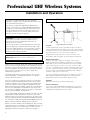
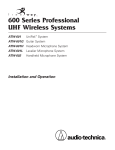
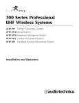
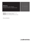
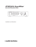
1400 Series Professional
UHF Wireless Systems
ATW-1451 UniPak™ Transmitter System
ATW-1452 Handheld Dynamic Microphone System
Installation and Operation
Professional UHF Wireless Systems
Installation and Operation
This device complies with part 15 of the FCC Rules.
Operation is subject to the condition that this device does
not cause harmful interference.
Receiver Installation
This device complies with INDUSTRY CANADA R.S.S.
210,en conformité avec IC: RSS-210/CNR210. Operation
is subject to the following conditions: 1) This device may
not cause harmful interference and 2) this device must
accept any interference received, including interference
which may cause undesired operation.
CAUTION! Electrical shock can result from removal of
the receiver cover. Refer servicing to qualified service
personnel. No user-serviceable parts inside. Do not
expose to rain or moisture.
The circuits inside the receiver and transmitter have been
precisely adjusted for optimum performance and compliance with federal regulations. Do not attempt to open the
receiver or transmitter. To do so will void the warranty,
and may cause improper operation.
Individuals with implanted cardiac pacemakers or
AICD devices: Please see notice on back cover.
Fig. A Receiver Location
Location
For best operation the receiver should be at least 3 ft. above
the ground and at least 3 ft. away from a wall or metal surface
to minimize reflections. The transmitter should also be at least
3 ft. away from the receiver, as shown in Figure A.
Keep antennas away from noise sources such as motors,
automobiles, and neon lights, as well as large metal objects.
Thank you for choosing an Audio-Technica professional wireless
system. You have joined thousands of other satisfied customers
who have chosen our products because of their quality, performance and reliability. This Audio-Technica wireless microphone
system is the successful result of years of design and
manufacturing experience.
Output Connections
There are two audio outputs on the back of the receiver:
balanced (160 mV) and unbalanced (280 mV). Use shielded
audio cable for the connection between the receiver and the
mixer. If the input of the mixer is a 1/4" jack, connect a cable
from the 1/4" unbalanced audio output on the back of the receiver to the mixer. If the input of the mixer is an XLR-type input,
connect a cable from the balanced XLR-type audio output on
the back of the receiver to the mixer.
This professional wireless system includes a receiver and
either a body-pack or a handheld transmitter on a specific
crystal-controlled frequency.
The two isolated audio outputs permit simultaneous feeds to
both unbalanced and balanced inputs. For example, both a
guitar amp and a mixer can be driven by the receiver.
The receiver features true diversity reception. Two antennas
feed two completely independent RF sections on the same
frequency; automatic logic circuitry continuously compares and
selects the superior received signal, providing better sound
quality and reducing the possibility of interference and dropouts.
The receiver is half-width for a standard 19" (1U) rack mount.
Two receivers (on different frequencies) can be mounted side
by side, using an AT8628 joining plate kit.
Antennas
Attach the antennas to the antenna input jacks.
Introduction
The versatile UniPak™ body-pack transmitter has both low- and
high-impedance inputs plus a bias connection, for use with
dynamic and electret condenser microphones, as well as Hi-Z
instrument pickups. Both the handheld and UniPak transmitters
use internal 9-volt batteries and have Off/Standby/On switches,
battery condition indicators, and battery-save switches.
Please note that in multiple-system applications there must be
a transmitter-receiver combination on a separate frequency for
each input desired (only one transmitter for each receiver).
Operating frequency information will be found on page 7.
2
Power Connections
Connect the included AD1205A AC adapter to the DC power
input on the back of the receiver. Then plug the adapter into
a standard 120 volt 60 Hz AC power outlet.
Receiver Controls and Functions
Fig. B Receiver Front Panel
8
1
2
POWER
6
4
UHF
DIVERSITY
RECEIVER
ANT. A
80
92 106 126 140
dB SPL
8
7
AF LEVEL
AF LEVEL
1
2
3
4
RF LEVEL
3
5
A
B
MIN
TUNER
ANT. B
MAX
5
Fig. C Receiver Rear Panel
11
9
12
GROUND LIFT
DC 12V~18V
500 mA
SQUELCH ADJ.
AF OUT GROUND
BALANCED
10
AF OUT
UNBALANCED
13
Front Panel Controls and Functions (Fig. B)
1. TUNER “A” ANTENNA JACK: Antenna connector for
tuner “A.” Attach the antenna directly, or extend it with
an antenna cable.
Rear Panel Controls and Functions (Fig. C)
2. POWER SWITCH/INDICATOR: Press switch on, and the
“Power” indicator will light.
10. BALANCED AUDIO OUTPUT JACK: XLRM-type connector.
A standard 2-conductor shielded cable can be used to
connect the receiver output to a balanced aux-level input
on a mixer.
3. RF SIGNAL LEVEL INDICATOR: Indicates the strength of
the RF signal received from the transmitter. The LEDs
will light up from left to right.
4. AF LEVEL INDICATOR: Indicates the audio modulation
level of the received signal. (Not affected by the setting
of the AF Level control.)
5. TUNER OPERATION INDICATOR: Indicates which tuner
has the better reception and is in operation.
6. AF LEVEL CONTROL: Adjusts the level at both audio
output jacks.
7. TUNER “B” ANTENNA JACK: Antenna connector for
tuner “B.” Attach the antenna directly, or extend it with
an antenna cable.
9. SQUELCH CONTROL: Adjusts level of noise-muting circuit
(preset at factory but can be adjusted as circumstances
warrant).
11. GROUND LIFT SWITCH: Disconnects the ground pin of
the balanced output (10) from ground. Normally, the switch
should be to the left (ground connected). If hum caused by
a ground loop occurs, slide switch to the right.
12. UNBALANCED AUDIO OUTPUT JACK: 1/4" phone jack.
Can be connected to an unbalanced aux-level input of
a mixer or tape recorder.
13. DC POWER INPUT: For the provided AD1205A AC adapter,
or other 12-18V DC source. (Receiver requires 500 mA.)
8. MOUNTING ADAPTERS: For mounting the receiver in any
standard 19" rack. Attach to receiver with screws supplied.
3
Transmitter Setup
Battery Selection
An alkaline 9-volt battery is recommended.
UniPak™ Transmitter Battery Installation
1. Slide off the battery cover as shown in Figure D.
2. Carefully insert a fresh 9-volt alkaline battery, observing
correct polarity as marked inside the battery compartment.
The transmitter housing is designed to prevent incorrect
installation of the battery. Do not force the battery in.
3. Replace the battery cover (Fig. E).
Fig. D
Microphone
Trimmer (MT)
Guitar Trimmer
(GT)
Battery Condition Indicator
The red battery condition indicator (Fig. H/I) should light strongly
with a fresh battery. As the battery weakens, the indicator will
grow dimmer. When the indicator becomes very dim or goes
out, there is little life left in the battery. Replace it at once for
continued operation of the transmitter.
Battery-Save Switch
All transmitters feature battery-save switches (Fig. D/F). As
supplied, the switch is set in the “H” (high) position for maximum range. Switching to the “L” (low) position increases battery
life by reducing power. (Note: Effective range decreases when
the switch is set at the “L” position.)
Fig. H
Fig. I
Power Switch Battery Condition
Indicator
Off/Standby/On
Battery Condition
Indicator
BATT.
OFF ST ON
INPUT
POWER BATT. ANT
UniPak™
TRANSMITTER
ST.BY
ON
Battery-Save Switch
(under screwdriver clip)
Battery Polarity
Diagram
Fig. E
Handheld Transmitter Battery Installation
1. While holding the upper part of the transmitter body just
below the ball-screen, unscrew the lower body cover and
slide it downward to expose the battery compartment.
2. Lift the white “battery keeper” arm, and insert a 9V battery.
Be certain to observe correct polarity as marked inside the
battery compartment (Fig. F). The transmitter housing is
designed to prevent incorrect installation of the battery.
Do not force the battery in.
3. Replace the lower body cover. Do not overtighten.
Fig. F
Battery Polarity
Diagram
Battery-Save
Switch
Fig. G
Gain Trimmer
(VR1)
Screwdriver
4
Input
Connector
OFF
Antenna
Power Switch
On/Standby/Off
UniPak Transmitter Input Connection
Connect an audio input device (microphone or guitar cable)
to the audio input connector on the bottom of the transmitter.
A number of Audio-Technica professional microphones and
cables are available separately, pre-terminated with a UniPak
input connector (see “Optional System Accessories” on
page 6.)
Transmitting Antenna
The UniPak transmitter includes a permanently-attached
flexible antenna. For best results, allow the antenna to hang
freely and full length from the bottom of the transmitter. If the
received signal is marginal, experiment with different transmitter positions on your body or instrument; or try repositioning
the receiver. Do not attempt to remove, replace or change
the length of the transmitting antenna.
System Operation
Check the frequency of the system against the chart on page 7
to ensure you have the proper frequency for your area.
Operating frequency is shown on the back panel of the
receiver and on the transmitter.
Turn down the AF Level control of the receiver as well as
the mixer. Switch on the receiver only. Do not switch on the
transmitter yet.
Receiver On . . .
The power indicator will light up.
Transmitter On . . .
The transmitters have a 3-position power switch. When the
switch is set to “Standby,” the transmitter produces RF with no
audio signal. When the switch is “On,” the transmitter produces
both RF and audio.
Receiver Squelch
The squelch control on the back of the receiver is preset at the
factory, but can be adjusted if you must use the system in an
area with considerable RF interference. If there is audio output
from the receiver when your transmitter is off, adjust the
squelch control so the system will receive the signal from
your transmitter but “squelch” or eliminate the unwanted
background RF noise. This adjustment can cause a reduction in
useable range of the wireless transmitter, so set the control to
the lowest position that reliably mutes the unwanted RF signals.
Input Level Adjustment
Input trimmer controls in the transmitters enable you to use
microphones or guitars with different sensitivities, or to adjust
for different acoustic levels.
Adjusting Input Levels – UniPak Transmitter
Slide the battery cover off the top part of transmitter and
remove the screwdriver from its clip (Fig. D). Gently turn the
“MT” (mic trimmer) and “GT” (guitar trimmer) controls to their
full counter-clockwise positions.
CAUTION! The small trimmer controls are delicate; use
only the supplied screwdriver. Do not force the trimmers
beyond their normal 180 o range of rotation.
Return the screwdriver to its storage clip when not in use.
• Microphone: Adjusting input level
While speaking/singing into the microphone at typically-loud
levels, carefully turn the MT control clockwise while watching
the receiver's AF Level indicator. Increase the MT control setting until the maximum audio output of the mic lights about
three or four LED units on the receiver's AF Level indicator.
Do not set the level too high (indicated by the red LED
lighting). At normal audio levels, only the first two or perhaps
three LEDs should light. (When using a guitar, return the MT
control setting to minimum.)
• Guitar/Instrument: Adjusting input level
While playing at typically-loud levels, carefully turn the GT
control clockwise while watching the receiver's AF Level indicator. Increase the GT control setting until the maximum
audio output lights about three or four LED units on the
receiver's AF Level indicator. Do not set the level too high
(indicated by the red LED lighting). At normal audio levels,
only the first two or perhaps three LEDs should light. (When
using a microphone, return the GT control setting to
minimum.)
After adjusting input levels, return the screwdriver to its clip
and reinstall the battery cover. No further transmitter gain
adjustments should be needed, as long as the input device
and the acoustic input level are not changed.
Adjusting Input Level – Handheld Transmitter
Unscrew the lower body cover and slide it downward, exposing
the screwdriver and gain trimmer (Fig. G). Remove the screwdriver and gently turn the gain trimmer control to its full
counter-clockwise position.
While speaking/singing into the microphone at typically-loud
levels, carefully turn the trimmer control clockwise while
watching the receiver’s AF Level indicator. Increase the control
setting until the maximum audio output of the mic lights
about three or four LED units on the receiver's AF Level indicator. Do not set the level too high (indicated by the red LED
lighting). At normal audio levels, only the first two or perhaps
three LEDs should light.
Return the screwdriver to its clip and close and secure the
lower body. (Make certain that the white “battery keeper”arm
is inside the body.) No further transmitter gain adjustments
should be needed, as long as the acoustic input does not
change significantly.
Ten Tips To Obtain The Best Results
1. Use only fresh alkaline batteries. Do not use “general purpose”
(carbon-zinc) batteries.
2. Position the receiver so that it has the fewest possible obstructions
between it and the normal location of the transmitter.
Line-of-sight is best.
3. The transmitter and the receiver should be as close together as
conveniently possible, but no closer together than three feet.
4. The receiver antennas should be in the open and away from
any metal.
8. If the AF Level control of the receiver is set too high, it may
over-drive the input of the mixer or clip the output of the receiver,
causing distortion. Conversely, if the receiver output is set too
low, the overall signal-to-noise ratio of the system may be reduced.
Adjust the output level of the receiver so the highest sound pressure
level going into the microphone (or the loudest instrument playing
level) causes no input overload in the mixer, and yet permits the
mixer level controls to operate in their “normal” range (not set
too high or too low). This provides the optimum signal-to-noise for
the entire system.
5. A receiver cannot receive signals from two transmitters at the
same time.
9. Turn the transmitter off when not in use. Remove the battery if
the transmitter is not to be used for a period of time.
6. In the UniPak transmitter, the “MT” or “GT” input control not in
use should be set to minimum.
10. In multiple-system applications, set the battery-save switches
on Low if possible, to reduce the chance of intermodulation
problems.
7. For best operation, all the RF Level LEDs should be lit (maximize
RF input); but only the first two or three AF Level LEDs should be
lit (don't overmodulate).
5
Specifications†
OVERALL SYSTEM
Operating Frequency
Frequency Stability
Modulation Mode
Maximum Deviation
Operating Range
Operating Temperature Range
Frequency Response
RECEIVER
Receiving System
Image Rejection
Signal-to-noise Ratio
Total Harmonic Distortion
Sensitivity
Audio Output
Unbalanced
Balanced
Output Connectors
Unbalanced
Balanced
Power Supply
Dimensions
Weight
Accessories Included
UHF band, 732 MHz to 746 MHz
±0.005%
FM
±15 kHz
200' minimum
40° F (4° C) to 110° F (43° C)
100 Hz to 15 kHz
UNIPAK ™ TRANSMITTER
RF Power Output
Spurious Emissions
Dynamic Range
Input Connections
Battery
Current Consumption
Battery Life
Dimensions
Dual independent receivers, automaticswitching diversity reception
45 dB minimum
95 dB at 10 kHz deviation (IEC-weighted),
maximum modulation 15 kHz
≤1% (10 kHz deviation at 1 kHz)
≤20 µV for 60 dB S/N (IEC -weighted)
280 mV (at 1 kHz, ±10 kHz deviation,
10k ohm load)
160 mV (at 1 kHz, ±10 kHz deviation,
10k ohm load)
/4" phone jack
XLRM-type
12-18V DC, 500 mA
8.27" (210.0 mm) W x 1.93" (49.0 mm) H
x 9.88" (251.0 mm) D
2.9 lbs (1.3 kgs)
Two antennas, rack mount adapters,
AD1205A AC adapter
1
Net Weight (without battery)
HANDHELD TRANSMITTER
RF Power Output
Spurious Emissions
Dynamic Range
Microphone Element
Battery
Current Consumption
Battery Life
Dimensions
Net Weight (without battery)
Accessory Included
50 mW Max
Under federal regulations
≥90 dB
High impedance, low impedance, bias
9V (NEDA type 1604) alkaline, not included
50 mA typical
Approximately 8 hours in High position
Approximately 10 hours in Low position
2.56" (65.0 mm) W x 4.33" (110.0 mm) H
x 1.00" (25.4 mm) D
3.2 oz (90 grams)
50 mW Max
Under federal regulations
≥90 dB
Dynamic unidirectional
9V (NEDA type 1604) alkaline, not included
50 mA typical
Approximately 8 hours in High position
Approximately 10 hours in Low position
9.53" (242.0 mm) long, 2.13" (54.0 mm)
diameter
12.3 oz (350 grams)
AT8431 stand clamp
† In the interest of standards development, A.T.U.S. offers full details on its test methods
to other industry professionals on request.
Optional System Accessories
MICROPHONES AND CABLES
AT829cW
AT829 miniature cardioid condenser microphone only,
terminated for use with UniPak transmitter. Includes
clothing clip and windscreen.
MT830cW
MT830R subminiature omnidirectional condenser
microphone only, terminated for use with UniPak
transmitter. Includes clothing clip and windscreen.
MT830cW-TH “Theater” model, same as MT830cW except beige color
mic and cable for concealment.
AT831cW
AT831b miniature cardioid condenser microphone only,
terminated for use with UniPak transmitter. Includes
clothing clip and windscreen.
AT851cW
AT851a surface-mount wide-range hemi-cardioid condenser
microphone only, terminated for use with UniPak transmitter.
AT857AMLcW AT857AMLa 19" gooseneck cardioid microphone only,
terminated for use with UniPak transmitter. Mounts to
5
/8"-27 thread. Includes windscreen.
ATM35cW
ATM35 high-intensity cardioid condenser microphone only,
terminated for use with UniPak transmitter. Includes AT8418
clip-on instrument mount.
ATM73cW
ATM73a headworn cardioid condenser microphone only,
terminated for use with UniPak transmitter.
ATM75cW
ATM75 headworn cardioid condenser microphone only,
terminated for use with UniPak transmitter. Includes
windscreens and cable clip.
PRO 8HEcW
PRO 8HEx headworn hypercardioid dynamic microphone,
terminated for use with UniPak transmitter. Includes
windscreen and cable clip.
6
PRO 35xcW
AT-GCW
XLRW
PRO 35x cardioid condenser microphone only, terminated
for use with UniPak transmitter. Includes AT8418 clip-on
instrument mount.
Hi-Z instrument/guitar cable with 1/4" phone plug,
terminated for use with UniPak transmitter.
Connecting cable for UniPak transmitter with an XLRF-type
input connector, for Lo-Z microphones with XLRM-type
output terminations.
TRANSMITTER ACCESSORIES
ATW-VP10
Vinyl pouch with belt clip to hold UniPak transmitter.
AT8114
Foam windscreen for handheld transmitter.
AT8141
Water-resistant pouch for UniPak transmitter.
AT8431
Stand clamp for handheld transmitter, 5/8"-27 threads.
RECEIVER ACCESSORIES
AT8628
Mounting plate adapter allows rack-mounting two
ATW-R14 receivers side-by-side in a single 19"
rack space.
ATW-D70
UHF (728-750 MHz) unity-gain antenna distribution system
provides two “1-in, 4-out” RF channels; connects a pair of
antennas to as many as four diversity receivers. Includes
four DC interconnect cables to power up to four ATW-R14
receivers, eight RF output cables and two rack-mount
adapters. Mounts in a single (1U) 19" rack space.
Wireless Operating Frequencies
Frequency Selection
Each transmitter/receiver system operates on a single factoryaligned, crystal-controlled frequency. Available frequencies are
shown in the chart below.
RF Interference
If you encounter receiving interference (from other than an
operating TV station), often it can be eliminated by adjusting
the receiver’s squelch control, as described on page 5.
Because the 732-746 MHz frequencies are shared with TV
broadcasting, frequency selection is partially dependent upon
which TV broadcast channels are in operation where the wireless system is to be used.
Please note that wireless frequencies are shared with other
radio services. According to Federal Communications
Commission regulations,“Wireless microphone operations are
unprotected from interference from other licensed operations
within the band. If any interference is received by any
Government or non-Government operation, the wireless
microphone must cease operation...”
Operating frequency is specified by a three-character code,
such as “57V,” in addition to the actual frequency in MHz.
The frequency of each transmitter appears on a label on the
outside of the unit. The frequency of each receiver appears on
a label on the back of the unit and the frequency of each system appears on the outer carton. For future reference, please
record them in the space provided below.
If you need assistance with operation or frequency selection,
please contact your dealer or the A-T professional division.
Extensive wireless information also is available on the A-T
Web site at www.audio-technica.com.
System Operating Frequencies
UHF TV Band (732-746 MHz)
• For use only where there is no TV Channel 57:
• For use only where there is no TV Channel 58:
• For use only where there is no TV Channel 59:
Freq. Code
Freq. (MHz)
57R
57V
58F
58G
58K
58L
59K
59Q
59R
59S
732.650
733.000
735.600
735.950
736.650
737.000
742.700
744.100
744.850
745.200
Aside from the TV channel restrictions above, multi-channel systems may combine up to all 10 frequencies. Due to the unique
conditions encountered in any complex system, the following guidelines may be helpful:
• Use the Low-power transmitter setting to reduce the possibility of interference.
• Maintain the maximum possible spacing between transmitters and receivers, and between transmitters.
• 1400 Series operating frequencies have been selected for optimum compatibility. However, other sources of RF energy can
affect the overall performance of the multi-mic system in ways which cannot be predicted. Only on-site trials with all RF
equipment in operation can determine the overall system functionality.
For future reference, please record your system information here (the serial numbers appear
inside the battery compartment of each transmitter, and on the bottom of each receiver):
Operating Frequency
Freq. Code ____ ____ ____
Frequency ____ ____ ____ • ____ ____ ____ MHz
Receiver
Model __________________
Serial Number ____ ____ ____ ____ ____ ____ ____
Transmitter
Model __________________
Serial Number ____ ____ ____ ____ ____ ____ ____
7
One-Year Limited Warranty
Audio-Technica professional wireless systems purchased in the U.S.A. are warranted for one year from date of purchase by Audio-Technica U.S., Inc.
( A.T.U.S.) to be free of defects in materials and workmanship. In event of such defect, product will be repaired promptly without charge or, at our
option, replaced with a new product of equal or superior value if delivered to A.T.U.S. or an Authorized Service Center, prepaid, together with the
sales slip or other proof of purchase date. Prior approval from A.T.U.S. is required for return. This warranty excludes defects due to normal wear,
abuse, shipping damage, or failure to use product in accordance with the instructions. This warranty is void in the event of unauthorized repair or
modification, or removal or defacing of the product labeling.
For return approval and shipping information, contact the Service Dept., Audio-Technica U.S., Inc., 1221 Commerce Drive, Stow, Ohio 44224.
Except to the extent precluded by applicable state law, A.T.U.S. will have no liability for any consequential, incidental, or special damages; any
warranty of merchantability or fitness for particular purpose expires when this warranty expires.
This warranty gives you specific legal rights, and you may have other rights which vary from state to state.
Outside the U.S.A., please contact your local dealer for warranty details.
Notice to individuals with implanted cardiac pacemakers or AICD devices:
Any source of RF (radio frequency) energy may interfere with normal functioning of the implanted device. All wireless microphones have low-power transmitters (less than 0.05 watts output) which are unlikely to cause difficulty,
especially if they are at least a few inches away. However, since a “body-pack” mic transmitter typically is placed
against the body, we suggest attaching it at the belt, rather than in a shirt pocket where it may be immediately adjacent
to the medical device. Note also that any medical-device disruption will cease when the RF transmitting source
is turned off. Please contact your physician or medical-device provider if you have any questions, or experience any
problems with the use of this or any other RF equipment.
Audio-Technica U.S., Inc., 1221 Commerce Drive, Stow, Ohio 44224 330/686-2600 www.audio-technica.com
P51201-B/W ©2000 Audio-Technica U.S., Inc. Printed in U.S.A.