1
Agilent OL
Instrument Controller
Installation and
Configuration Guide
Notices
Copyright © Scientific Software, Inc
1997-2005 © Agilent Technologies,
Inc. 2005-2007.
No part of this manual may be
reproduced in any form or by any
means (including electronic storage
and retrieval or translation into a
foreign language) without prior
agreement and written consent
from Agilent Technologies, Inc. as
governed by United States and
international copyright laws.
Manual Part Number
G4650-90017
Edition
Document Revision 3.3B
February, 2007
Printed in USA
Agilent Technologies, Inc.
6612 Owens Dr.
Pleasanton, CA 94588-3334
Warranty
The material contained in this
document is provided “as is,” and
is subject to being changed,
without notice, in future editions.
Further, to the maximum extent
permitted by applicable law, Agilent
disclaims all warranties, either
express or implied, with regard to
this manual and any information
contained herein, including but not
limited to the implied warranties of
merchantability and fitness for a
particular purpose. Agilent shall not
be liable for errors or for incidental
or consequential damages in
connection with the furnishing, use,
or performance of this document or
of any information contained
herein. Should Agilent and the user
have a separate written agreement
with warranty terms covering the
material in this document that
conflict with these terms, the
warranty terms in the separate
agreement shall control.
Technology Licenses
The hardware and/or software
described in this document are
furnished under a license and may
be used or copied only in
accordance with such license.
Restricted Rights Legend
If software is for use in the
performance of a U.S. Government
prime contract or subcontract,
Software is delivered and licensed
as "Commercial computer
software" as defined in DFAR
252.227-7014 (June 1995), or as a
"commercial item" as defined in
FAR 2.101(a) or as "Restricted
computer software" as defined in
FAR 52.227-19 (June 1987) or any
equivalent agency regulation or
contract clause. Use, duplication or
disclosure of Software is subject to
Agilent Technologies’ standard
commercial license terms, and nonDOD Departments and Agencies of
the U.S. Government will receive no
greater than Restricted Rights as
defined in FAR 52.227-19(c)(1-2)
(June 1987). U.S. Government users
will receive no greater than Limited
Rights as defined in FAR 52.227-14
(June 1987) or DFAR 252.227-7015
(b)(2) (November 1995), as
applicable in any technical data.
Contents
1
Using This Guide.................................................................................... 1
Introduction ...............................................................................................................1
Who Should Read This Guide?...............................................................................1
2
Before You Start..................................................................................... 1
3
Installing AIC 5000 for Agilent OL ....................................................... 3
Install the Agilent Instrument Controller Network Appliance .........................3
Configure the Agilent Instrument Controller Device..........................................5
Install the SS420x.....................................................................................................6
Connect the Instruments.........................................................................................7
Finish Configuring the Instrument Controller......................................................8
Select Components ..................................................................................................8
Configure the SS420x...............................................................................................9
Configure Instruments ...........................................................................................11
4
Reset the AIC 5000 to Factory Defaults ............................................ 11
Important notes for the Reset to Factory Adapter ...........................................12
5
Replacing an AIC Revision A or B ..................................................... 12
6
AIC 5000 Specifications ...................................................................... 13
7
Installing AIC Revision B for Agilent OL........................................... 15
Install the Agilent Instrument Controller Network Appliance .......................15
Configure the Agilent Instrument Controller Device........................................16
AIC Installation and Configuration
iii
Install the SS420x................................................................................................... 18
Connect the Instruments ...................................................................................... 18
Finish Configuring the Instrument Controller.................................................... 19
Select Components................................................................................................ 19
Configure the SS420x ............................................................................................ 20
Configure Instruments........................................................................................... 22
8
Installing AIC Revision A for Agilent OL ...........................................23
Install the Agilent Instrument Controller Network Appliance ....................... 23
Configure the Agilent Instrument Controller Device ....................................... 24
Install the SS420x................................................................................................... 26
Connect the Instruments ...................................................................................... 26
Finish Configuring the Instrument Controller.................................................... 27
Select Components................................................................................................ 27
Configure the SS420x ............................................................................................ 28
Configure Instruments........................................................................................... 29
9
Using the Reset to Factory Adapter for AIC Rev A/B .....................31
Important notes for the Reset to Factory Adapter................................... 31
10 Updating an AIC....................................................................................33
11 Notes ......................................................................................................33
12 Specifications for AIC Rev A and B ...................................................35
iv
AIC Installation and Configuration
1 Using This Guide
Introduction
This guide describes how to install the Agilent Instrument Controller
(AIC) for use with Agilent OL. The Agilent Instrument Controller is
a network appliance that controls instruments and acquires data
digitally. Each Agilent Instrument Controller can control and
acquire digital data from up to 4 GC or LC instruments, or up to 16
analog channels of data (SS420x required), up to 2 photodiode array
detectors (PDA) or combinations of the above.
Separate sections in this guide discuss how to install each of the
three versions of the Agilent Instrument Controller: AIC 5000,
Revision A, and Revision B. The AIC 5000 is black in color and has
“AIC 5000 Instrument Controller” stenciled on the front of the unit.
Revision A is black in color and is marked with a “Revision A”
sticker on the rear or has no sticker. Revision B is silver in color and
is marked with a “Revision B” sticker on the rear.
Who Should Read This Guide?
This document is designed for the system administrator who will
install the Agilent Instrument Controller.
2 Before You Start
In order to configure the Agilent Instrument Controller device, you
will need a computer with Microsoft Internet Explorer and .NET
Framework 1.1 or 2.0 installed. You will also need the network
crossover cable provided with the Agilent Instrument Controller.
Using This Guide
1
Note
Place the AIC 5000 on a flat, stable surface.
You can position the unit in the upright
position using the included stand, or in the
horizontal position.
Always place AIC Revision A and Revision B
units in the upright position, using the
included stand.
Note
2
The AIC 5000 is shipped with a USB
memory stick, which is required in case a
Reset to Factory Settings is necessary.
Please keep this in a safe place for future
use.
Using This Guide
3 Installing AIC 5000 for Agilent OL
Use this procedure for installing and configuring the Agilent
Instrument Controller AIC 5000. The AIC 5000 is black in color and
has “Instrument Controller 5000” stenciled on the front of the unit.
Install the Agilent Instrument Controller Network
Appliance
Installing the AIC 5000
1.
Before installing or configuring an Agilent Instrument
Controller, make sure all OL ECM and ICM components are
installed.
2.
Verify which version of the Agilent Instrument Controller
you have. Installation of the AIC 5000 version is described in
this section. See later sections in this guide for instructions
on using the other two versions, Revision B and Revision A.
3.
Create an “AIC User” account. (See “Add a New User” in the
online help for how to do this.) This should be a unique user
with full administrator rights (call this user “aicuser” for
example).
4.
From the Administration tab, click Global Administration,
and then right click Agilent Instrument Controller. In the
General tab of the Properties dialog box, type the AIC user
account name and password, along with the account and
domain for the user. This will be used by the AICs to
communicate with the OL server. Click OK to close the
dialog box.
3
5.
Disconnect the computer from the network and change the
TCP/IP settings to use the static IP address 192.168.1.2.
Contact a network administrator if you need assistance
doing this.
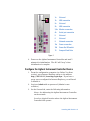
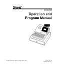
6.
Connect one end of the supplied network crossover cable
(Part Number G4690-60000) to the computer and the other
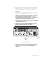
end to the AIC network port shown in Figure 1. Be sure to
use the network port indicated in Figure 1 — The PCI
network interface card installed in the AIC 5000 is reserved
exclusively for connecting instruments to the unit.
7.
Verify that the 115V/220V voltage selector is set correctly for
your location. (See Figure 1.)
8.
Connect the AIC 5000 to a properly grounded AC outlet
using the supplied power cable. (See Figure 1.)
Figure 1. AIC 5000 Connections
9.
4
Power on the AIC 5000 and wait for initialization. The AIC
5000 produces a two-tone beep when initialization is
complete.
Installing the AIC 5000
Configure the Agilent Instrument Controller Device
1.
2.
3.
From the configuration computer (see “Before You Start”
section), open Internet Explorer and go to the address
http://192.168.1.1/iconsetup/login.aspx. If you have a
proxy server configured in Internet Explorer, you will need
to disable it.
Log in as Admin with no password. (Admin is casesensitive.)
On the General tab, enter the following information:
Name: for addressing the Agilent Instrument Controller
on the network
Location: physical location where the Agilent Instrument
Controller will operate
Comment: any additional comment you want to make
4.
5.
6.
OL server URL: for example http://aspen. Be sure to use
a fully-qualified host name or address.
Click Submit.
On the Hardware tab, click Configure to the right of Intel®
PRO/100 VE Network, and make the following selections:
Obtain an IP address automatically
Obtain DNS server address automatically
Click Submit.
.
Note
Installing the AIC 5000
Static IPs and DNS are also supported. If
these are used, they must be within the same
subnet range as the web server. See
Configure an Agilent Instrument Controller in
the online help for details.
7.
From the Advanced tab on the computer, click Initialize.
8.
Click Yes to confirm you want to initialize the Agilent
Instrument Controller. You may need to scroll down to see
5
this button. A dialog box appears asking you if you want to
close the window. Click Yes.
9.
Immediately disconnect the crossover cable from the Agilent
Instrument Controller and connect the laboratory network.
The AIC gives a short two-tone beep when initialization is
complete. If initialization fails, the AIC gives one or more
single longer beeps.
10. To verify the initialization was completed, log into OL as a
user with administrator privileges. From the Administration
tab, click Global Administration followed by Agilent
Instrument Controller.
11. Verify that the AIC appears. If it does not appear, wait 5
minutes, click on another node (such as Account
Administration), and then click Agilent Instrument
Controller again. If the AIC still does not appear, there are
several possibilities, given below. Once you have resolved the
problem, go back to the beginning of this section and repeat
the steps to set up the AIC.
•
The address for the OL server was entered
incorrectly. On some networks, it may be necessary
to enter a fully-qualified name (for example
http://aspen.agilent.com).
•
The laboratory network cable was not connected
soon enough after clicking Initialize (see step 7-9,
above).
Install the SS420x
If your instrument provides an analog detector signal, you must use
the SS420x analog to digital converter box. If you are using a digital
instrument, you do not need an SS420x.
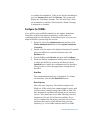
Connect the SS420x interface to the Agilent Instrument Controller
using the serial communications cable provided. Connect one end of
the cable to the serial port on the back of the SS420x. Connect the
other end of the cable to any serial port on the Agilent Instrument
Controller (see Figure 2.) Make sure each connector is tightened.
6
Installing the AIC 5000
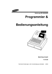
Figure 2. AIC 5000 Instrument and SS420x Connections
Plug the SS420x power supply into an appropriate electrical outlet.
Connect the power cord from the power supply into the receptacle
on the rear of the SS420x.
The red power LED should light. The four (4) green channel
indicator LEDs sequentially light up during the power-up test. When
the test is complete, the green LEDs will go off and the interface is
ready to use. If this sequence does not successfully complete, the
SS420x must be powered off and then on again.
Connect the Instruments
Connect the instruments you will be using with the Agilent
Instrument Controller. If you are using a digital instrument, connect
it to the Agilent Instrument Controller using the appropriate
connector on the back of the Agilent Instrument Controller (see
Figure 2). If your AIC 5000 includes an optional RS-232, SCSI, or
GPIB interface card, it is installed in the upper PCI slot. The network
interface card is installed in the lower PCI slot.
Note
Installing the AIC 5000
If you are using a SCSI instrument, it must be
powered ON prior to connecting it to the Agilent
Instrument Controller.
7
If you are using an instrument with an analog signal, you need to
connect it to an SS420x attached to the Agilent Instrument
Controller using the connectors on the rear of the SS420x. For
details on how to connect an instrument to the SS420x, see the
documentation provided with the SS420x.
If you are connecting an instrument to the AIC 5000 through the
optional GPIB interface card, you must use the included GPIB port
extender (Part Number 10834A).
If you are connecting an instrument to the AIC using Ethernet, you
must use the instrument network connector indicated in Figure 2.
Note
Use only the Agilent-supplied network interface
card in the AIC 5000.
Finish Configuring the Instrument Controller
1.
From the OL Explorer, go to the Administration tab, choose
Global Administration, and click Agilent Instrument
Controller.
2.
In the list of Agilent Instrument Controller units, double
click on the Agilent Instrument Controller name that you
entered earlier.
Wait until you see a “Ready” status for the AIC before
proceeding. After the Agilent Instrument Controller has
finished re-initializing and shows a “Ready” status, you will
need to make sure to install all instruments or A/D devices
to be used and then set up the Agilent Instrument Controller
to recognize these devices. (See Select Components section
below.) Click Submit to continue.
3.
Select Components
Before you can use the Agilent Instrument Controller, you must tell
it what instrument components will be in use, so the Agilent
Instrument Controller can communicate with them. The following
steps are used to select the components.
8
Installing the AIC 5000
1.
From OL, select the Administration tab and then click
Global Administration, followed by Agilent Instrument
Controller.
2.
Double-click the name of the Agilent Instrument Controller
where the instruments are connected and then select the
Components tab.
3.
Select each hardware component for this Agilent Instrument
Controller by clicking the box adjacent to the component
name. You may select as many components as you wish. If
you are using analog acquisition with an SS420x, select
Generic System.
4.
Press the Submit button to finish. If this is the first
installation, after selecting the components and clicking
Submit, click the Install Now button. You will be prompted
to confirm the installation. If this is not the first installation,
go to the Advanced tab and click Restart. The system will
display the “Installing” message. The AIC will “beep” when
the installation is complete. Wait until the “Ready” message
is displayed to continue.
Configure the SS420x
If you will be using an SS420x attached to the Agilent Instrument
Controller (required for analog acquisition), it will need to be
configured using the OL software, as described below. If you are not
using an SS420x, you may skip this section.
1. From OL, select the Administration tab and then click
Global Administration followed by Agilent Instrument
Controller.
Installing the AIC 5000
2.
Double-click the name of the Agilent Instrument Controller
where the SS420x is connected and then select the
Hardware tab.
3.
Locate SS420x under Boards and then click Configure.
4.
From the SS420x configuration dialog, select the Serial port
to which the SS420x is connected and then check the
Installed box to enable the configuration of the interface.
Then proceed to select the appropriate settings for the
interface.
9
Baud Rate
The communication baud rate is displayed. To change the
baud rate, click Set Baud Rate.
Base Frequency
Select the base frequency. The default setting for the SS420x
is 10 Hz, which gives optimal signal to noise, and can be used
in countries using either 50Hz or 60Hz. The base frequencies
available will depend on the baud rate chosen. If the baud
rate is less than 38400bps, the base frequencies 100 and 120
will not be available. If you choose a higher base frequency,
you must select a base frequency that can be evenly divided
into your line frequency (i.e. 30 for 60Hz countries and 25 for
50Hz countries). If selected incorrectly, you may see line
frequency noise on your chromatogram. For best
performance, select a base frequency close to the maximum
sampling frequency you will be using to acquire data.
Sampling frequencies available in the Acquisition Setup
portion of the method will reflect the Base Frequency
selected.
Range
For each channel used, select the button next to the signal
range for the detector connected to that channel.
Information
This area is for information only. It contains manufacturing
information about the interface box that may be required in
service situations. If the box is not recognized, the
“Connection Status” field will display “Not Connected”.
5.
10
After you complete the dialog, click Submit. To read the
current settings for the SS420x, click Read SS420x Settings.
To abort the operation without changing any settings, click
Cancel.
Installing the AIC 5000
Configure Instruments
Before you can use the Agilent Instrument Controller to acquire
data, each instrument must be configured using the Agilent OL
software. See the Agilent OL help for instructions on how to
configure instruments.
4 Reset the AIC 5000 to Factory Defaults
The AIC 5000 is shipped with a USB memory stick that is used to
reset the AIC settings to the factory defaults.
To load the factory default on the USB memory stick,
1.
Connect the blank memory stick to an available USB port on
a PC with a USB port and a CD ROM drive.
2.
Browse the Agilent OL software CD for the \Addon\AIC
Reset to Factory Adapter\SSIConfig folder, and copy this
folder to the root of the memory stick.
3.
Verify the presence of the file {37F06863-452F-4002-AB6C8D48B175FA82} (no file extension) in the \SSIConfig folder
of the memory stick. DO NOT test the memory stick on a
configured AIC, as this will cause a reset to factory settings.
To reset an AIC to factory defaults,
1. Turn on AIC. The AIC produces two short beeps when
initialization is complete.
2. AFTER power up is completed, plug the Reset to Factory
adapter into any USB port on the AIC.
3. The reset to factory will start.
4. The AIC will start beeping.
5. Remove the Reset to Factory adapter. You may remove it as
soon as the beeping starts. The adapter must be removed
before the AIC restarts itself.
6. The AIC will restart automatically and then proceed with the
rest of the reset to factory.
Installing the AIC 5000
11
Important notes for the Reset to Factory Adapter
•
The Reset to Factory Adapter will cause a reset to factory
defaults on any AIC, not just the one it was delivered with.
•
It can be reused any number of times.
•
Plug the Reset to Factory Adapter in AFTER the AIC is
powered on. Don’t plug it in before turning on the AIC.
•
The Reset to Factory Adapter must be connected to start the
reset to factory, but it must not be connected for the restarts
of the AIC that are involved in the automatic reset to factory
procedure.
•
After a reset to factory, the IP address of the AIC will be
reset to 192.168.1.1.
5 Replacing an AIC Revision A or B
If you are replacing an AIC Revision A or Revision B with an AIC
5000, install the AIC 5000 by following the instructions in “Installing
the AIC 5000 for Agilent OL”, above.
12
Installing the AIC 5000
6 AIC 5000 Specifications
Dimensions
Height
3.95 inches
10.3 cm
Width
13.3 inches
33.78 cm
Depth
15.1 inches
38.35 cm
Approximate Weight
21 lb
9.53 kg
Operating
50° to 95° F
10° to 35° C
Nonoperating
-22° to 140° F
-30° to 60° C
Operating
10–90%
10–90%
Nonoperating (38.7° C max wet bulb)
5–95%
5–95%
Operating
10,000 ft
3048 m
Nonoperating
30,000 ft
9144 m
Temperature Range
Relative Humidity (noncondensing)
Maximum Altitude (unpressurized)
Note
Operating temperature is derated 1.0° C per 300 m
(1000 ft) to 3000 m (10,000 ft) above sea level, no
direct sustained sunlight. Maximum rate of change
is 10° C/Hr. The upper limit may be limited by the
type and number of options installed.
Power Supply
115 V
230 V
Operating Voltage Range
90–132 VAC
180–264 VAC
Rated Voltage Range
100–127 VAC
200–240 VAC
Rated Line Frequency
50–60 Hz 50–60 Hz
Power Output
185 W
185 W
Rated Input Current (maximum)
5 A @ 100 VAC
2.5 A @ 200 VAC
Maximum
971 BTU/hr
245 kg-cal/hr
Typical (idle)
256 BTU/hr
65 kg-cal/hr
Heat Dissipation
Installing the AIC 5000
13
Note
14
This system utilizes a passive power factor
corrected power supply when used in the 230V
mode. This allows the system to pass the CE mark
requirements for use in the countries of the
European Union.
Installing the AIC 5000
7
Installing AIC Revision B for Agilent OL
Use this procedure for the Agilent Instrument Controller Revision B.
Revision B of the AIC is silver in color and is marked with a
“Revision B” sticker on the rear.
Install the Agilent Instrument Controller Network
Appliance
Installing AIC Rev. B
1.
Before installing or configuring an Agilent Instrument
Controller, make sure all OL ECM and ICM components are
installed.
2.
Verify which revision of the Agilent Instrument Controller
you have. Installation of Revision B (silver in color) is
described in this section. Instructions on using Revision A
(black in color) is described later in this guide.
3.
Create an “AIC User” account. (See Add a New User in the
online help for how to do this.) This should be a unique user
with full administrator rights (call this user “aicuser” for
example).
4.
From the Administration tab, click Global Administration,
and then right click Agilent Instrument Controller. In the
General tab of the Properties dialog box, enter the AIC user
account name and password, along with the account and
domain for the user. This will be used by the AICs to
communicate with the OL server. Click OK to close the
dialog box.
5.
Disconnect the computer from the network and change the
TCP/IP settings to use the static IP address 192.168.1.2.
Contact a network administrator if you need assistance
doing this.
6.
Connect one end of the network crossover cable (Part
Number G4690-60000) to the computer and the other end to
the main network port of the Agilent Instrument Controller if
more than one network port is available. (See Figure 1.)
15
Figure 1. AIC Connectors for Revision B
7.
Power on the Agilent Instrument Controller and wait 5
minutes for initialization. The AIC will “beep” when
initialization is complete.
Configure the Agilent Instrument Controller Device
1.
16
From the configuration computer (see Before You Start
section), open Internet Explorer and go to the address
http://192.168.1.1/iconsetup/login.aspx. If you have a
proxy server configured in Internet Explorer, you will need
to disable it.
Installing AIC Rev. B
2.
3.
Log in as Admin with no password. (Admin is casesensitive.)
On the General tab, enter the following information:
Name: for addressing the Agilent Instrument Controller
on the network
Location: physical location where the Agilent Instrument
Controller will operate
Comment: any additional comment you want to make
4.
OL server URL: for example http://aspen.
On the Hardware tab, click the Configure link and make the
following selections:
Obtain an IP address automatically
Obtain DNS server address automatically
Note
5.
6.
Installing AIC Rev. B
Static IPs and DNS are are also supported. If
these are used, they must be within the same
subnet range as the web server. See the
Configure an Agilent Instrument Controller
topic in online help for details.
From the Advanced tab on the computer, click Initialize and
confirm you want to initialize the Agilent Instrument
Controller.
Immediately disconnect the crossover cable from the Agilent
Instrument Controller and connect the laboratory network.
The AIC will give two short “beeps” when initialization is
complete. If initialization fails, the AIC will give a single
longer “beep”.
7.
To verify the initialization was completed, log into OL as a
user with administrator privileges. From the
Administration tab, click Global Administration followed
by Agilent Instrument Controller.
8.
Verify that the AIC appears. If it does not appear, wait 5
minutes, click on another node (such as Account
Administration), and then click the Agilent Instrument
Controller again. If the AIC still does not appear, there are
17
several possibilities, given below. Once you have resolved
the problem, go back to the beginning of this section and
repeat the steps to set up the AIC.
•
The address for the OL server was entered
incorrectly. On some networks, it may be necessary
to enter a fully-qualified name (for example
http://aspen.agilent.com).
•
The laboratory network cable was not connected
soon enough after clicking Initialize (see steps 5-6,
above).
Install the SS420x
If your instrument provides an analog detector signal, you must use
the SS420x analog to digital converter box. If you are using a digital
instrument, you do not need an SS420x.
Connect the SS420x interface to the Agilent Instrument Controller
using the serial communications cable provided. Connect one end of
the cable to the serial port on the back of the SS420x. Connect the
other end of the cable to the serial port on the Agilent Instrument
Controller (see Figure 1.) Make sure each connector is tightened.
Plug the SS420x power supply into an appropriate electrical outlet.
Connect the power cord from the power supply into the receptacle
on the rear of the SS420x.
The red power LED should light. The four (4) green channel
indicator LED’s will sequentially light up during the power-up test.
When the test is complete, the green LED’s will go off and the
interface is ready to use. If this sequence does not successfully
complete, the SS420x must be powered off and then on again.
Connect the Instruments
Connect the instruments you will be using with the Agilent
Instrument Controller. If you are using a digital instrument, connect
it to the Agilent Instrument Controller using the appropriate
connector on the back of the Agilent Instrument Controller (see
Figure 1.)
18
Installing AIC Rev. B
Note
If you are using a SCSI instrument, it must be
powered ON prior to connecting it to the Agilent
Instrument Controller.
If you are using an instrument with an analog signal, you need to
connect it to an SS420x attached to the Agilent Instrument
Controller using the connectors on the rear of the SS420x. For
details on how to connect an instrument to the SS420x, see the
documentation provided with the SS420x.
Finish Configuring the Instrument Controller
1.
From the OL Explorer, go to the Administration tab, choose
Global Administration, and click Agilent Instrument
Controller.
2.
In the list of Agilent Instrument Controller units, double
click on the Agilent Instrument Controller name that you
entered earlier.
Wait until you see a “Ready” status for the AIC before
proceeding. After the Agilent Instrument Controller has
finished re-initializing and shows a “Ready” status, you will
need to make sure to install all instruments or A/D devices
to be used and then set up the Agilent Instrument Controller
to recognize these devices. (See Select Components section
below.) Click Submit to continue.
3.
Select Components
Before you can use the Agilent Instrument Controller, you must tell
it what instrument components will be in use, so the Agilent
Instrument Controller can communicate with them. The following
steps are used to select the components.
1. From OL, select the Administration tab and then click
Global Administration, followed by Agilent Instrument
Controller.
2.
Installing AIC Rev. B
Double-click the name of the Agilent Instrument Controller
where the instruments are connected and then select the
Components tab.
19
3.
Select each hardware component for this Agilent Instrument
Controller by clicking the box adjacent to the component
name. You may select as many components as you wish. If
you are using analog acquisition with an SS420x, select
Generic System.
4.
Press the Submit button to finish. If this is the first
installation, after selecting the components and clicking
Submit, click the Install Now button. You will be prompted
to confirm the installation. If this is not the first installation,
go to the Advanced tab and click Restart. The system will
display the “Installing” message. The AIC will “beep” when
the installation is complete. Wait until the “Ready” message
is displayed to continue.
Configure the SS420x
If you will be using an SS420x attached to the Agilent Instrument
Controller (required for analog acquisition), it will need to be
configured using the OL software, as described below. If you are not
using an SS420x, you may skip this section.
1. From OL, select the Administration tab and then click Global
Administration followed by Agilent Instrument Controller.
2.
Double-click the name of the Agilent Instrument Controller
where the SS420x is connected and then select the
Hardware tab.
3.
Locate SS420x under Boards and then click Configure.
4.
From the SS420x configuration dialog, select the Serial port
to which the SS420x is connected and then check the
Installed box to enable the configuration of the interface.
Then proceed to select the appropriate settings for the
interface.
Baud Rate
The communication baud rate is displayed. To change the
baud rate, click Set Baud Rate.
20
Installing AIC Rev. B
Base Frequency
Select the base frequency. The default setting for the SS420x
is 10 Hz, which gives optimal signal to noise, and can be used
in countries using either 50Hz or 60Hz. The base frequencies
available will depend on the baud rate chosen. If the baud
rate is less than 38400bps, the base frequencies 100 and 120
will not be available. If you choose a higher base frequency,
you must select a base frequency that can be evenly divided
into your line frequency (i.e. 30 for 60Hz countries and 25 for
50Hz countries). If selected incorrectly, you may see line
frequency noise on your chromatogram. For best
performance, select a base frequency close to the maximum
sampling frequency you will be using to acquire data.
Sampling frequencies available in the Acquisition Setup
portion of the method will reflect the Base Frequency
selected.
Range
For each channel used, select the button next to the signal
range for the detector connected to that channel.
Information
This area is for information only. It contains manufacturing
information about the interface box that may be required in
service situations. If the box is not recognized, the
“Connection Status” field will display “Not Connected”.
5.
Installing AIC Rev. B
When the dialog is completed, click Submit. To read the
current settings for the SS420x, click the Read SS420x
Settings button. To abort the operation without changing
any settings, click Cancel.
21
Configure Instruments
Before you can use the Agilent Instrument Controller to acquire
data, each instrument must be configured using the OL software.
See the OL help for instructions on how to configure instruments.
22
Installing AIC Rev. B
8
Installing AIC Revision A for Agilent OL
Use this procedure to install Revision A of the Agilent Instrument
Controller. Revision A is black in color and is marked with a
“Revision A” sticker on the rear or has no sticker.
Install the Agilent Instrument Controller Network
Appliance
1.
Before installing or configuring an Agilent Instrument
Controller, make sure all OL ECM and ICM components are
installed.
2.
Create an “AIC User” account. (See Add a New User in the
online help for how to do this.) This should be a unique user
with full administrator rights (call this user “aicuser” for
example).
3.
From the Administration tab, click Global Administration,
and then do a right mouse click on Agilent Instrument
Controller. In the General tab of the Properties dialog box,
enter the AIC user account name and password, along with
the account and domain for the user. This will be used by
the AICs to communicate with the OL server. Click OK to
close the dialog box.
4.
Disconnect the computer from the network and change the
TCP/IP settings to use the static IP address 192.168.1.2.
Contact a network administrator if you need assistance
doing this.
5.
Connect one end of the network crossover cable (Part
Number G4690-60000) to the computer and the other end to
the main network port of the Agilent Instrument Controller if
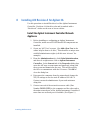
more than one network port is available. (See Figure 1.)
Installing AIC Revision A
23
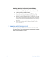
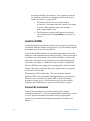
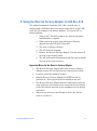
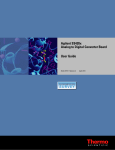
13
1a
Not used
1b
USB connection
2a
Not used
2b
USB connection
3,4a
Monitor connection
4b
Serial port connection
5
Not used
6
Not used
9
Network connection
12a
Power connection
12b
Power On/Off switch
13
Compact Flash Drive
Figure 1.
6.
Power on the Agilent Instrument Controller and wait 5
minutes for initialization. The AIC will “beep” when
initialization is complete.
Configure the Agilent Instrument Controller Device
1.
2.
3.
From the configuration computer (see Before You Start
section), open Internet Explorer and go to the address
http://192.168.1.1/iconsetup/login.aspx. If you have a
proxy server configured in Internet Explorer, you will need
to disable it.
Log in as Admin with no password. (Admin is casesensitive.)
On the General tab, enter the following information:
Name: for addressing the Agilent Instrument Controller
on the network
Location: physical location where the Agilent Instrument
Controller will operate
24
Installing AIC Revision A
Comment: any additional comment you want to make
4.
OL server URL: for example http://aspen.
On the Hardware tab, click the Configure link and make the
following selections:
Obtain an IP address automatically
Obtain DNS server address automatically
Note
5.
6.
7.
8.
From the Advanced tab on the computer, click Initialize and
confirm you want to initialize the Agilent Instrument
Controller.
Immediately disconnect the crossover cable from the Agilent
Instrument Controller and connect the laboratory network.
The AIC will give two short “beeps” when initialization is
complete. If initialization fails, the AIC will give a single
longer “beep”.
To verify the initialization was completed, log into OL as a
user with administrator privileges. From the
Administration tab, click Global Administration followed
by Agilent Instrument Controller.
Verify that the AIC appears. If it does not appear, wait 5
minutes, click on another node (such as Account
Administration), and then click the Agilent Instrument
Controller again. If the AIC still does not appear, there are
several possibilities, given below. Once you have resolved the
problem, go back to the beginning of this section and repeat
the steps to set up the AIC.
•
Installing AIC Revision A
Static IPs and DNS are are also supported. If
these are used, they must be within the same
subnet range as the web server. See the
Configure an Agilent Instrument Controller
topic in online help for details.
The address for the OL server was entered
incorrectly. On some networks, it may be necessary
to enter a fully-qualified name (for example
http://aspen.agilent.com).
25
•
The laboratory network cable was not connected
soon enough after clicking Initialize (see steps 5-6,
above).
Install the SS420x
If your instrument provides an analog detector signal, you must use
the SS420x analog to digital converter box. If you are using a digital
instrument, you do not need an SS420x.
Connect the SS420x interface to the Agilent Instrument Controller
using the serial communications cable provided. Connect one end of
the cable to the serial port on the back of the SS420x. Connect the
other end of the cable to the serial port on the Agilent Instrument
Controller (see Figure 1.) Make sure each connector is tightened.
Plug the SS420x power supply into an appropriate electrical outlet.
Connect the power cord from the power supply into the receptacle
on the rear of the SS420x.
The red power LED should light. The four (4) green channel
indicator LED’s will sequentially light up during the power-up test.
When the test is complete, the green LED’s will go off and the
interface is ready to use. If this sequence does not successfully
complete, the SS420x must be powered off and then on again.
Connect the Instruments
Connect the instruments you will be using with the Agilent
Instrument Controller. If you are using a digital instrument, connect
it to the Agilent Instrument Controller using the appropriate
connector on the back of the Agilent Instrument Controller (see
Figure 1.)
Note
If you are using a SCSI instrument, it must be
powered ON prior to connecting it to the Agilent
Instrument Controller.
If you are using an instrument with an analog signal, you need to
connect it to an SS420x attached to the Agilent Instrument
Controller using the connectors on the rear of the SS420x. For
26
Installing AIC Revision A
details on how to connect an instrument to the SS420x, see the
documentation provided with the SS420x.
Finish Configuring the Instrument Controller
1.
From the OL Explorer, go to the Administration tab, choose
Global Administration, and double click the Agilent
Instrument Controller.
2.
In the list of Agilent Instrument Controller units, double
click on the Agilent Instrument Controller name that you
entered earlier.
Wait until you see a “Ready” status for the AIC before
proceeding. After the Agilent Instrument Controller has
finished re-initializing and shows a “Ready” status, you will
need to make sure to install all instruments or A/D devices
to be used and then set up the Agilent Instrument Controller
to recognize these devices. (See Select Components section
below.) Click Submit to continue.
3.
Select Components
Before you can use the Agilent Instrument Controller, you must tell
it what instrument components will be in use, so the Agilent
Instrument Controller can communicate with them. The following
steps are used to select the components.
1. From OL, select the Administration tab and then click
Global Administration, followed by Agilent Instrument
Controller.
2.
Double-click the name of the Agilent Instrument Controller
where the instruments are connected and then select the
Components tab.
3.
Select each hardware component for this Agilent Instrument
Controller by clicking the box adjacent to the component
name. You may select as many components as you wish. If
you are using analog acquisition with an SS420x, select
Generic System.
4.
Press the Submit button to finish. If this is the first
installation, after selecting the components and clicking
Submit, click the Install Now button. You will be prompted
Installing AIC Revision A
27
to confirm the installation. If this is not the first installation,
go to the Advanced tab and click Restart. The system will
display the “Installing” message. The AIC will “beep” when
the installation is complete. Wait until the “Ready” message
is displayed to continue.
Configure the SS420x
If you will be using an SS420x attached to the Agilent Instrument
Controller (required for analog acquisition), it will need to be
configured using the OL software, as described below. If you are not
using an SS420x, you may skip this section.
1. From OL, select the Administration tab and then click
Global Administration followed by Agilent Instrument
Controller.
2.
Double-click the name of the Agilent Instrument Controller
where the SS420x is connected and then select the
Hardware tab.
3.
Locate SS420x under Boards and then click Configure.
4.
From the SS420x configuration dialog, select the Serial port
to which the SS420x is connected and then check the
Installed box to enable the configuration of the interface.
Then proceed to select the appropriate settings for the
interface.
Baud Rate
The communication baud rate is displayed. To change
the baud rate, click the Set Baud Rate button.
Base Frequency
Select the base frequency. The default setting for the
SS420x is 10 Hz, which gives optimal signal to noise, and
can be used in countries using either 50Hz or 60Hz. The
base frequencies available will depend on the baud rate
chosen. If the baud rate is less than 38400bps, the base
frequencies 100 and 120 will not be available. If you
choose a higher base frequency, you must select a base
frequency that can be evenly divided into your line
frequency (i.e. 30 for 60Hz countries and 25 for 50Hz
28
Installing AIC Revision A
countries). If selected incorrectly, you may see line
frequency noise on your chromatogram. For best
performance, select a base frequency close to the
maximum sampling frequency you will be using to
acquire data.
Sampling frequencies available in the Acquisition Setup
portion of the method will reflect the Base Frequency
selected.
Range
For each channel used, select the button next to the
signal range for the detector connected to that channel.
Information
5.
This area is for information only. It contains
manufacturing information about the interface box that
may be required in service situations. If the box is not
recognized, the “Connection Status” field will display
“Not Connected”.
When the dialog is completed, click Submit. To read the
current settings for the SS420x, click the Read SS420x
Settings button. To abort the operation without
changing any settings, click Cancel.
Configure Instruments
Before you can use the Agilent Instrument Controller to acquire
data, each instrument must be configured using the OL software.
See the OL help for instructions on how to configure instruments.
Installing AIC Revision A
29
30
Installing AIC Revision A
9 Using the Reset to Factory Adapter for AIC Rev A/B
The Agilent Instrument Controller (AIC) (Rev A and B only) is
shipped with a USB flash drive that, when connected to an AIC, will
reset the AIC settings to the factory defaults. To reset an AIC to
factory defaults,
1. Turn on AIC. The AIC produces two short beeps when
initialization is complete.
2. When power up is done, plug the Reset to Factory
adapter into any USB port on the AIC.
3. The reset to factory will start.
4. The AIC will start beeping.
5. Remove the Reset to Factory adapter. You may remove it
as soon as the beeping starts.
6. The AIC will restart automatically and then proceed with
the rest of the reset to factory.
Important Notes for the Reset to Factory Adapter
•
The Reset to Factory Adapter will cause a reset to factory
defaults on any AIC, not just the one it was delivered with.
•
It can be reused any number of times.
•
Plug the Reset to Factory Adapter in AFTER the AIC is
powered on. Don’t plug it in before turning on the AIC.
•
The Reset to Factory Adapter must be connected to start the
reset to factory, but it must not be connected for the restarts
of the AIC that are involved in the automatic reset to factory
procedure.
•
After a reset to factory, the IP address of the AIC will be
reset to 192.168.1.1.
Installing AIC Revision A
31
•
32
If you remove the special file on the Reset to Factory Adapter
or rename it, then the device will no longer cause a reset to
factory. Don’t use the device for anything other than
resetting an AIC to factory defaults
Installing AIC Revision A
10 Updating an AIC
This section applies only to the Revision A and Revision B versions
of the Agilent Instrument Controller.
For support purposes, it may occasionally be necessary to replace
the compact flash on the Agilent Instrument Controller. To do this,
use the following procedure.
1.
Turn OFF and unplug the AIC.
2.
Locate the compact flash on the upper rear of the AIC and
remove the plate covering it with a small screwdriver.
3.
Push the ejector button with the tip of a pen or a small
screwdriver to remove the existing compact flash card.
4.
Insert the update compact flash card.
5.
Plug in and turn ON the AIC and complete the steps for
Installing the Agilent Instrument Controller described in
Section 2 above.
11 Notes
Please review the following notes regarding use of the Agilent
Instrument Controller.
•
Installing AIC Revision A
Before the addition or removal of a USB component,
please turn off the AIC, unless instructed otherwise.
33
34
Updating an AIC
12 Specifications for AIC Rev A and B
Agilent Instrument Controller Revisions A and B
Environment
Operating temperature: 0oC to 40oC (32oF to 104oF)
Nonoperating temperature: -10oC to 60oC (-14oF to
140oF) Humidity: 0% to 90%
Power Switch
1 momentary “soft” power switch
Power Supply
External 40 watt auto-switching power adapter Input:
AC 100V-140V and 200V-260V, 45Hz~65Hz Output:
DC 12V 40 watt
Specifications for Rev A and B
35
Printed in the U.S.A. February, 2007
*G4650-90017*
G4650-90017