1
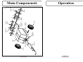
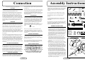
TM
Manufacturers of Britain’s No.1 Range of Garden Tractors and Ride-On Mowers
Version 1.0
Countax Limited, Countax House, Great Haseley, Oxford OX44 7PF
Tel: (01844) 278800 Fax: (01844) 278792
Email: [email protected] Website:www.countax.com
TM
All figures are approximate. We reserve the right to change specification and price without notice E&OE
© copyright 2000 Countax Limited
Powered
Lawngroomer
OPERATORS MANUAL
Wheel
Page 2
Draw bar
‘R’ Clip
Draw Bar
Locking Pin
Wheel
Chassis
Frame
Axle Support
Beam
Spiker
Spacer
Rear
Spindle
Slitter
Spiker L/H
fig 1
Tank
Spiker R/H
Main Componenets
Operation
Page 7
Connection
Assembly Instructions
mixed spray mixture, replace the filler cap and switch am and
operating lever.
Avoid getting your fingers trapped underneath.
SLITTING
This operation is carried out in the Spring. It prunes grass roots and
so promotes healthy growth throughout the season.
The slitter plates are not handed and do not have to be put on any
particular way round. They work equally well in either direction.
Make sure that the operating lever is in the down position, i.e:
lying flat along the plastic tank with the switch arm over it. Fit the
the 6 slitters (as illustrated in figure 1), 3 on either side of the rear
axle with spacing springs in between. Secure to the rear axle with
3/4" washers and R clips (fig 8). To operate use as with the spikers
described. Take care to protect against the torque of the springloaded operating lever especially when replacing it in the up
position.
SPRAYING
The Countax Lawngroomer s spraying facility comprises a 10
gallon (imperial) calibrated plastic tank housing a 1/2" submersible
impeller pump with a 12v motor which is driven from the tractor
battery. The pump is connected by flexible hose to a delavan nozzle
which is mounted in an aperture at the front of the plastic tank.
The electric cable to the pump runs from a plug on the draw bar via
a switch on the end of the switch on the end of the switch arm
through a rubber bung in the bottom of the plastic tank then through
a nylon conduit to the pump. The draw bar plug connects to a socket
on the tractor. For tractors not equipped with a socket, a conversion
kit is supplied.
The spray is turned ON and OFF by the switch at the end of
the switch arm. The nozzle sprays to a width of approximately
33". Do not run the pump dry. Switch it off as soon as the
plastic tank is empty. When you have finished spraying, clean
the system by placing one or two gallons of clean water in the
tank and spraying it out.
CALIBRATING
To make sure you get an accurate application of the spray it is
important to control the speed of the tractor. Since the pump is
not controlled by the tractor s speed it will run at a constant
rate. We therefore recommend that when spraying you travel
at a speed of around 3mph. At a constant pumping speed of
one gallon in 1 minute will thus be sprayed over 170 square
yards (90 square meters). From this you can see there is a
formula to calculate how much of the raw material
recommended by the manufacturers to cover this area must be
put into each gallon mixture e.g. for 25ml per 28sq yds per
gallon
107x25 — 95.5ml
28
There is not a speedometer on your Countax tractor. At a
constant speed of 3mph the tractor will cover 50 yards in 34
seconds. Great care is need to keep this speed constant — it is
just as important to avoid applying spray too sparsley as it is to
over-spray.
DRIVING TECHNIQUES
The spray nozzle is equipped with an anti-drip cut-off valve. There
is also a filter immediately behind the jet. The standard jet is the
D7.5, which passes one gallon in one minute 20 seconds. A priming
jet is situated in the side of the nylon tailpiece which holds the
nozzle to the plastic tank. This is a constant flow jet with the double
function of ensuring positive priming of the nozzle and providing
internal agitation to spray mixtures as yet not fully dissolved. If at
any time the nozzle fails to work, this priming jet should be checked
for blockages.
To be certain of the correct rate of application, you must take
care not to drive accurately and turn off the spray when
turning or stopping. You should avoid an overlap of anything
greater than a few inches.
Spray only on still days when rain is not expected; also take
care especially when using weedkiller, that the spray mixture
does not carry over on to surrounding vegetation.
JET AND FILTER REMOVAL
Hold the body of the nozzle to prevent it from turning, then turn the
winged cap-ring at the front of the nozzle clockwise. This releases
the cap-ring with the jet and the filter which lies in the nozzle body
immediately inside can easily be prised out carefully for cleaning.
Assemble in reverse order. The nozzle body can be removed from
the wall of the plastic tank in a similar fashion using the spanner
illustrated to hold the tank adapter. However when replacing always
make sure that the end of the nozzle jet is lying horizontal before
you start spraying. This will ensure even spraying to left and right.
SPRAYING OPERATION
SAFETY PRECAUTIONS
i
IT IS ESSENTIAL WHEN USING ANY CHEMICAL
SPRAY PRODUCTS SUCH AS WEEDKILLERS AND
FERTILIZERS, TO OBSERVE ALL THE
MANUFACTURER S INSTRUCTIONS FULLY. WE
FURTHER RECOMMEND THE USE OF GLOVES AND
PROTECTIVE GOGGLES WHEN MIXING SUCH
PRODUCTS AND ALSO WHEN FILLING THE
CONTAINER ON YOUR LAWNGROOMER.
The filler cap is underneath the switch arm and the operating lever.
Both of these have to be lifted to get at the filler cap. Raise the
operating lever with caution. Load the plastic tank with the pre-
Page 6
The Countax Electric Lawngroomer has been designed for use
with all models of Countax garden tractors, as well as all other
popular models of tractor and ride-on mower, which have a
12v electric Charging System and electrical Power Take
Off plug.
fi g 2
1 x SPANNER
The electric Lawngroomer is straightforward to assemble.
The Lawngroomer comes in one package which should be
emptied and all the contents checked against the parts
list (fig 2).
4 x 3/4'' ID x 1.1/4 OD
WASHERS
4 x SLITTER SPRING
We suggest that if the packing box is to be kept, the sharp
copper staples that sealed it are removed completely for
safety s sake.
2 x 1/4'' x 1/2'' LONG 4 x 1/4'' NYLOC
NUTS
POSISCREWS
The Lawngroomer comes partly assembled from the Countax
factory. It is recommended that you read these instructions
right through, identifying the various components used in each
step before actually starting to assemble.
1. Identify the Switch Arm, the components which has
"Lawngroomer" written on it. Identify also the springloaded operating lever with a T cut in it. Both Levers come
already in place. Raise each Lever, taking care with the
torque on the spring loaded operating lever, and take out the
plastic tank, placing it to the left of the machine as you look
at it from the front. Be careful, when moving the plastic
tank, not to disconnect the wires. Return operating lever to
down position (see fig 3).
2. Identify the draw bar. Now take off the pozidrive screws
and nuts that secure the switch arm to the front of the
chassis and slide the draw bar into the front of the chassis.
Next connect the electrical lead from the draw bar to the
terminals at the front of the chassis. Ensure that blue wire
from the plug connects to the white from the switch
(see fig 3).
3. Refit the Pozidrive screws and nuts to the switch arm and
the front of the chassis. Tighten them sufficiently to hold the
pieces firmly, but do not so tightly that the switch arm
cannot swivel properly (see fig 3). Now the draw bar is in
place, slide the draw bar pin through the holes in the front of
the chassis and the draw bar itself and secure with a small
R clip. Take care however, when inserting the pin, not to
catch the wiring running through the draw bar (fig 3).
4. Identify the Axle Support Beam. Apart from the 2 large
holes in each end of it s sides the Axle Support Beam has 2
smaller holes towards one end, this is the front. Now with
the operating lever the down position, insert this front end
of the axle support beam through the aperture in the rear of
the chassis. Fit the wheel axle, passing it through both sides
of the chassis and through the holes in the front end of the
axle support beam. Identify and slip in a 1/4"x1/2" hex head
bolt through the axle beam and axle and add a washer and
Nyloc nut. Do up loosley (see fig 4).
FLAT WASHER
1/4'' (LIGHT DUTY)
2 x 1/4'' x 1.1/2'' BOLTS
1 x 'R' CLIP (SMALL)
2 x 7/16'' STEEL
NUTS
ASSEMBLY INSTRUCTIONS
3 x 'R' CLIPS (LARGE)
1 x DRAW BAR LOCKING PIN
2 X HUB CAPS
1 x DRAW BAR LOCKING PIN
2 x 3/4'' ID
x 1.1/2'' OD WASHER
Page 3
4 x 7/16'' ID
x 7/8'' OD
WASHERS
4 x E CLIPS
2 x SPIKER SPACERS
F i gu r e 2
Plasti c
T ank
fi g 3
Swi tch Ar m
Oper ati ng
Lever
Connect
Electr i cal
Leads
Chassi s
Pozi scr ews
and Nu ts
Dr awbar
Dr aw Bar
Pi n
Assembly
5. Bring the operating lever into the up position. This action will
lower the link plate down towards the axle support beam. Pull the
link plate away from the unit whilst raising the operating lever up
to the lock position (see fig 5).
6. Then raise the axle support beam from the rear and this will
enable you to slip the 2 flanges on the link plate into place on the
axle support beam. It may be necessary to tap the link into its
final position and align the two sets of holes (see fig 6).
6.1. IMPORTANT: Take great care during this operation, since there
is considerable torque on the operating lever and on the link plate.
Assembly
fi g 4
/4”
1
11/2”
Axle
Su ppor t
Beam
ON NO ACCOUNT ATTEMPT TO REMOVE THE SPRING
SPECIAL TOOLS ARE REQUIRED FOR ITS REMOVAL
AND REPLACEMENT
7. When the link is in it s proper position, the 2 flanged screw holes
will be over the corresponding holes in the axle beam. Secure it
with the two 1/4"x1/2" long Poziscrew head bolts, and
Nyloc nuts.
8. Now tighten the nut on the bolt connecting the axle beam to
the axle.
9. Next replace the plastic tank into it s original position, taking care
not to trap the wiring.
10. The operating lever is now pulled forward and down onto the
plastic tank and the switch arm on top of it.
X
Oper ati ng
Lever
Li nk
Plate
Page 4
fi g 6
Pu ll Up
fi g 7
Ali gn two
holes
9”
(2 3cm)
Tractor models differ in tow height and it is important that the
Lawngroomer operates at as near level stance as possible. The
level of the machine is controlled from the towing pin which
is adjustable in height. Simply move the 2 lock-nuts, above
and below the draw bar (see fig 8).
For this all season operation, first make sure that the operating
lever is in the DOWN position; ie: lying flat along the plastic
tank with the switch arm over it. Now fit the 3 left hand and 3
right hand spiker plates onto the rear axle as illustrated, with
the loose spacers immediately inside each of the outer spiker
plates. Make sure that the spiker plates are fitted so that the
spike of each plate is pointing downwards, forward of the
spindle in the direction of travel. The spikes will then work
with the minimum of disturbance to the lawn. Secure onto the
rear axle with 3/4" washers and an R slip (see fig 1 & 9).
fi g 9
Cor r ect
fi g 10
To lower the spikes into the work position, raise the switch
arm and raise the operating lever until it locks over the axle
support beam. Put the switch arm back down along the plastic
tank.
/4” ID 11/4” OD
3
WASHER
/4” ID 11/4” OD
3
WASHER
E- Cli p
CAP
Wheel
Lock Nu ts
SPIKING
T ap
E- Cli p
T owi ng Pi n
Heavy Du ty
1. When the hitching the Lawngroomer to your tractor for the
first time (preferably on a flat piece of ground), insert the
tow pin into the tractor s towing hitch bracket from
underneath and secure with an R clip through the top of
the tow pin.
2. Now adjust the nuts on the tow pin, up or down as
necessary until the Lawngroomer draw bar is 9" (23cms)
above the ground at it s front end. Then tighten the nuts to
hold the draw bar at that height (Nyloc nuts are not used
here, these are just plain nuts). You will not have to repeat
this operation unless you use the Lawngroomer with
another model of garden tractor.
Axle
Su ppor t
Beam
11. Now fit the wheels. Locate the grooves on either side of the axle.
In the innermost groove, place an E clip, then a 3/4"x1/4"
washer, and then another E clip. Repeat process on other wheel.
Finish off by pushing the plastic caps over the washers (see fig 7).
12. Identify the rear spindle and slide it through the holes in the rear
of the axle beam and secure it to the axle beam with a 1/4"x11/2"
hex head bolt, washer and Nyloc nut. The rear spindle is now
ready for you to attach the spikers or slitters.
13. An electrical socket is supplies with this Lawngroomer, it is for
use on tractors not fitted with a 12v power take off. On Countax
tractors not already fitted with this PTO socket, fitting and wiring
the electrical connector is very straightforward: at the rear of the
tractor to the right hand side of the tow hitch bracket is a rubber
blanking grommet; remove this to install the PTO socket. It is
important to ensure a good earth between the socket and the
chassis of the tractor and to achieve that it is necessary to remove
paint from approx 1/4" around the rear of the hole which then
must be smeared with Petroleum (not grease). Remove the nut
and large starlock washer from the rear of the socket, insert the
threaded part of the socket through the hole, then refit the starlock
washer and the retaining nut. On the Countax tractor, connect the
rear of the socket to the red/voilet wire which is adjacent to
the socket.
F lat
Washer s7/16”
Your Countax Electric Lawngroomer is an extremely versatile
machine. To produce and maintain excellent lawns, the
Lawngroomer offers solid tine spiking for weed control and
liquid fertilizer application.
SETTING THE DRAW BAR HEIGHT
fi g 5
i
T ow Hi tch
The attachments for spiking and slitting are fitted as required
to the rear spindle, and the spraying nozle is fitted in an
aperture at the front of the plastic tank, where it can be seen by
the operator.
Wheel
Axle
CAUTION:
Take great care when pushing the operating lever
into this position. It is spring loaded and there is
strong torque. Avoid getting your fingers trapped
underneath it. Hold firmly, preferably standing in a
well balanced position.
fi g 8
OPERATING INSTRUCTIONS
CAUTION:
Perform this operation with great care because this lever is
spring-loaded. It is best to grip the handle firmly, preferably
when you are standing in a well balanced position. The same
level of care should be exercised when raising the spikes by
lowering the operating lever back into it s down position.
i
Page 5
Wr ong
Dr aw Bar