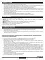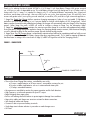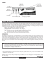
1
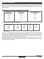
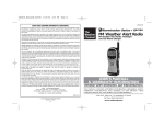
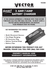
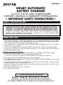
VEC1087 A
SMART AUTOMATIC
BATTERY CHARGER
12 VOLT 2/6/10 AMP CHARGE RATES
OWNER’S MANUAL & WARRANTY INFORMATION
• IMPORTANT SAFETY INSTRUCTIONS •
WARNING – RISK OF EXPLOSIVE GASES
1. WORKING IN VICINITY OF A LEAD-ACID BATTERY IS DANGEROUS. BATTERIES
GENERATE EXPLOSIVE GASES DURING NORMAL BATTERY OPERATION. FOR THIS
REASON, IT IS OF UTMOST IMPORTANCE THAT EACH TIME BEFORE USING YOUR
CHARGER, YOU READ THIS MANUAL AND FOLLOW THE INSTRUCTIONS EXACTLY.
2. To reduce risk of battery explosion, follow these instructions and those published by the battery
manufacturer and manufacturer of any equipment you intend to use in vicinity of battery. Review
cautionary markings on these products and on engine.
GENERAL BATTERY SAFETY
1. Use this charger for charging a 12 VOLT LEAD-ACID battery only. It is not intended to supply power to a low voltage
electrical system other than in automotive applications. Do not use this battery charger for other types of batteries,
these may burst and cause injury to persons and damage to property.
2. Use of an attachment not recommended or sold by the battery charger manufacturer may result in a risk of fire,
electric shock, or injury to persons.
3. To reduce risk of damage to electric plug and cord, pull by plug rather than cord when disconnecting charger.
4. An extension cord should not be used unless absolutely necessary. Use of an improper extension cord could result
in a risk of fire and electric shock.
If extension cord must be used, make sure:
a. That pins on plug of extension cord are the same number, size, and shape as those of plug on charger.
b. That extension cord is properly wired and in good electrical condition; and
c. That wire size is AWG #14 (14 gauge) to 100 feet and AWG #12 for distances over 100 feet.
5. Do not operate charger with damaged cord or plug - replace immediately.
6. Do not operate charger if it has received a sharp blow, been dropped, or otherwise damaged in any way; take
it to a qualified service technician.
7. Do not disassemble charger; take it to a qualified service technician when service or repair is required. Incorrect
reassembly may result in a risk of electric shock or fire.
8. To reduce risk of electric shock, unplug charger from outlet before attempting any maintenance or cleaning. Turning
off controls will not reduce this risk.
9. Do not expose charger to rain, snow or use when wet.
10. Never charge a frozen battery.
This device complies with Part 15 of the FCC Rules.
SAVE THESE INSTRUCTIONS:
This manual contains important safety and operating instructions for battery charger Model VEC1087 AA
4140 SW 28TH WAY, FT. LAUDERDALE, FL 33312 • TEL: 954-584-4446 • FAX: 954-584-5556 • TOLL-FREE 866-584-5504
PERSONAL PRECAUTIONS AND SAFETY
1. Another person should be close enough to come to your aid when you work near a lead-acid battery.
2. Fresh water and soap should be nearby in case battery acid contacts skin, clothing, or eyes.
3. Wear eye protection and protective clothing. Avoid touching eyes or skin while working with a battery. If acid particles
or corrosion gets into eyes immediately flood eye with cold water (Eye Wash Station) for at least 10 minutes and get
medical attention immediately.
4. If battery acid contacts skin or clothing, wash immediately with soap and water.
5. NEVER smoke or allow a spark or flame in vicinity of battery or engine.
6. CAUTION: Dropping metal tool or other object onto battery may cause spark, short-circuit battery or other electrical
components and may cause explosion.
7. Remove personal metal items such as rings, bracelets, necklaces, and watches when working with a lead-acid battery.
Lead-acid batteries can produce a short-circuit current high enough to cause a severe burn.
GROUND AND AC POWER CORD CONNECTION
Charger should be grounded to reduce risk of electric shock. Charger is equipped with an AC cord having grounding
conductor and a grounding plug. The plug must be plugged into a properly installed and grounded 110/120VAC outlet
in accordance with all local codes and ordinances. (See Figure 1.)
DANGER! NEVER alter AC cord or plug – if it will not fit outlet, have proper outlet installed by a qualified
electrician. Improper connection may result in an electric shock.
This battery charger is for use on a 110/120VAC circuit, and has a grounding plug that looks like the plug shown in
FIGURE 1A. If a properly grounded outlet is not available, a temporary adapter (like the adapter shown in FIGURE 1B),
may be used to connect this plug to a two-pole receptacle as shown in FIGURE 1B. The temporary adapter should be
used ONLY until a properly grounded outlet can be installed by a qualified electrician.
DANGER! Before using adapter as shown (FIGURE 1B), be sure the center screw of outlet plate is grounded.
The green-colored rigid ear or tab extending from adapter must be connected to a properly grounded outlet. Make
certain it is grounded. If necessary, replace original outlet cover plate screw with a longer screw that will secure adapter
ground tab to outlet cover plate and connect to grounded outlet.
FIGURE 1A
FIGURE 1B
ADAPTER (B)
GROUNDING PIN (A)
METAL SCREW
GROUNDING
MEANS
USE OF AN ADAPTER IS NOT ALLOWED IN CANADA. IF A GROUNDING TYPE RECEPTACLE IS
NOT AVAILABLE, DO NOT USE THIS APPLIANCE UNTIL THE PROPER OUTLET IS INSTALLED BY A
QUALIFIED ELECTRICIAN.
2
VEC1087 A
REV101103
PREPARING TO CHARGE
1. Determine voltage of battery by referring to car owner's manual.
2. If it is necessary to remove battery from vehicle to charge, or to clean terminals, always remove grounded terminal
from battery first. Make sure all accessories in the vehicle are off, so as not to cause an arc.
3. Clean battery terminals. Be careful to keep corrosion from coming in contact with eyes.
4. Add distilled water in each cell until battery acid reaches level specified by battery manufacturer. This helps purge
excessive gas from cells. Do not overfill. For a battery without cell caps (maintenance free), carefully follow
manufacturer's charging instructions.
5. Study all battery manufacturers' specific precautions such as removing or not removing cell caps while charging
and recommended rates of charge.
6. Area around battery should be well ventilated while battery is being charged.
7. Make sure the initial charging rate does not exceed battery manufacturers requirement.
CHARGER LOCATION
1. Locate charger as far away from battery as cables permit.
2. NEVER place charger directly above battery being charged; gases from battery will corrode and
damage charger.
3. NEVER allow battery acid to drip on charger when reading specific gravity or filling battery.
4. NEVER operate charger in a closed-in area or restrict ventilation in any way.
5. Marine batteries must be removed and charged on shore.
6. Do not set a battery on top of charger.
DC CONNECTION PRECAUTIONS
1. Connect and disconnect DC output clamps only after removing AC cord from electric outlet.
2. Never allow clamps to touch each other.
3. Attach clamps to battery posts and check for secure connection. This will hold clamps securely on terminals
and helps to reduce risk of sparking.
FOLLOW THESE STEPS WHEN BATTERY IS INSTALLED IN VEHICLE. A SPARK NEAR BATTERY MAY CAUSE BATTERY EXPLOSION.
TO REDUCE RISK OF A SPARK NEAR BATTERY:
a. Position AC and DC cords to reduce risk of damage by hood, door, or moving engine part.
b. Stay clear of fan blades, belts, pulleys, and other parts that can cause injury to persons.
c. Check polarity of battery posts. POSITIVE (POS, P, +) battery post usually has larger diameter than
NEGATIVE (NEG, N,-) post.
d. Determine which post of battery is grounded (connected) to the chassis. If negative post is grounded to chassis
as in most vehicles), see (e). If positive post is grounded to the chassis, see (f).
e. For negative-grounded vehicle, connect POSITIVE (RED) clamp from battery charger to POSITIVE (POS, P, +) post
of battery. Connect NEGATIVE (BLACK) clamp to vehicle chassis or engine block away from battery. Do not connect
clip to carburetor, fuel lines, or sheet-metal body parts. Connect to heavy gauge metal part of the frame or engine block.
f. For positive-grounded vehicle, connect NEGATIVE (BLACK) clamp from battery charger to NEGATIVE (NEG, N, -)
ungrounded post of battery. Connect POSITIVE (RED) clamp to vehicle chassis or engine block away from battery.
Do not connect clip to carburetor, fuel lines, or sheet-metal body parts. Connect to a heavy gauge metal part of the
frame or engine block.
g. When disconnecting charger, turn switches to off, disconnect AC cord, remove clamp from vehicle chassis, and then
remove clamp from battery terminal.
h. See operating instructions for length of charge information.
i. Do not charge the battery while the engine is operating.
3
VEC1087 A
REV101103
INTRODUCTION AND FEATURES
Thank you for selecting the Vector® Model VEC1087 A, 2/6/10 Amp 12 volt Smart Battery Charger. With proper care and
use, it will give you years of dependable service. This model battery charger has a high charge rate of up to 10 amps, and low
charge rate of up to 2 amps. It is intended for charging only 12 volt lead-acid batteries- maintenance free, conventional
automotive, marine deep cycle and gel - that are usually used in cars, trucks, farm equipment, boats, RVs and SUVs, lawn
mowers and garden tractors, motorcycles, personal watercraft, snowmobiles, ATVs, and various light commercial applications.
1. Stage One- Rapid Start Charge- delivers maximum charging amperage to “wake up” any serviceable 12 Volt battery
and allows for quick engine starting in just 5 minutes (based on midsize vehicle battery at 50% charge level). When
battery reaches a maximum safe predetermined voltage, the charger will automatically move into Stage 2 of the charging
process. When Stage One ends, a BEEP will sound to indicate a change to Stage Two, the Absorption Stage.
2. Stage Two- Absorption Charge maintains the maximum possible charge at a constant safe predetermined voltage.
During the phase, voltage absorption regulation charge, the charging voltage remains constant, while the actual charging
current is reduced to allow for the maximum proper internal chemical energy transfer.
3. Stage Three- Top-Off Charge voltage is automatically maintained and reduced to a predetermined level while current
is adjusted for a safe, effective 100% battery charge (step-down regulation mode). This is ideal for topping off batteries
that have been in storage. At the conclusion of Stage 3, a BEEP will signal the end of the "charging process."
FIGURE 1 - CHARGE CURVE
FEATURES
Stage One
BEEP
BEEP
Stage Two
Stage Three
OFF
FIGURE 2A
FIGURE 2B
CHARGING COMPLETE LED LIT
FEATURES
• The unit has three Charge Rate settings, controlled by one switch:
a) 2 amps: smaller batteries as in lawn mowers, snowmobiles, motorcycles, etc.
b) 6 amps: middle sized batteries such as in watercraft and motorcycles
c) 10 amps: automobile batteries
• Microprocessor controlled to monitor for proper operation and for fault detection.
• High Frequency switch-mode operation for pure DC output.
• Rapid charging three stage output.
• Built-in self-resetting thermal shutdown to protect against damage from conditions.
• Heavy-duty cables and clamps are corrosion-resistant for better connections.
• Self storage of cables and clamps.
• Connect to side or top-mount battery terminals.
• Single beep tone indicates a button is pressed or a mode change occurs
• UL-Listed
VEC1087 A
4
REV101103
FIGURE 2
10A LED
INDICATOR
6A LED
INDICATOR
2/6/10A
Charge Rate
Button Switch
2A LED
INDICATOR
Fault LED
Reverse Polarity LED
Charging Complete
CONTROLS AND INDICATORS
There are four (4) LED indicators and one button switch (select charge rate) that make up the controls and indicators for this
charger. Refer to FIGURE 3. Three vertical bar LEDs indicate the selected charge rate. A zero charge rate is indicated by "unlit"
Charge Rate LEDs. There is no charger output when all LEDs bars are unlit the charger is not charging. Pressing the 2/6/10A
switch selects the desired charge rate. Four lit LEDs indicate the following:
Power - When lit indicates AC is applied to the charger.
Charging Complete - Indicates the battery is fully charged.
Fault - Indicates one or more abnormal conditions including Reverse Polarity.
(If the Fault LED lights, refer to TROUBLESHOOTING for details)
Rev. - Lights when clamps are incorrectly connected to battery terminals.
OPERATION:
Once clamps are connected, AC is connected and there is no reverse polarity condition, press the 2/6/10A button switch
and the charger will begin charging at 2 Amps. Pressing the 2/6/10A switch a second time will advance the charge rate
to 6A, then 10A. Pressing the button switch again will turn OFF the charger output and all LED bars will be "unlit." To
return to 2A press the Charge Rate button switch. This charger has three user selected charge rates 2, 6 and 10 amps.
Pressing the 2/6/10A switch button selects the desired charge rate. The selected Charge Rate is indicated by a lit vertical
LED bar.
NOTE: Each time the charger rate is changed, the charger sounds a beep. The only time the selected charge rate does
not display at the full selected rate is when the battery is nearly full and charging at either steps two or three. The
display will be showing a slowing charge rate. To return to 2A, press the 2/6/10A button. When the battery is
fully charged, the “Charging Complete” LED is lit.
• Small 12-volt DC batteries such as those used in motorcycles, garden tractors, ATVs, jet skis, and snowmobiles can be
damaged by high charge rates.
ALWAYS select the 2 Amp setting to charge this type of battery. For slower charging time on larger batteries, select
the 2 Amp setting.
5
VEC1087 A
REV101103
FIGURE 3
WARNINGS:
• THERE ARE NO USER-SERVICEABLE PARTS IN THIS UNIT.
• DO NOT OPEN THE UNIT. IT MUST BE RETURNED TO VECTOR FOR PROFESSIONAL TESTING AND REPAIR. OPENING
THE UNIT WILL VOID THE MANUFACTURER'S WARRANTY.
WARNING: If battery size is not known, charge at the 2 Amp rate. DO NOT overcharge batteries.
ALWAYS ensure that charge rate corresponds to the12 volt battery (size) being charged.
CHARGING IF BATTERY IS INSTALLED IN A VEHICLE
a) Check polarity of battery posts - For top-mounted battery posts, the Positive post (marked POS, P, +) usually has a
larger diameter than the Negative battery post (marked NEG, N, -). For side-mounted battery terminals, the terminals
are marked Positive -red and Negative -black.
b) Attach charger clamps to battery connections, as follows, ensuring a good connection (if there is a mistake, the Reverse
Polarity Indicator will light):
NEGATIVE-GROUNDED VEHICLE: Connect the POSITIVE (RED) charger clamp to the POSITIVE (POS, P, +) battery post.
Then, connect the NEGATIVE (BLACK) charger clamp to the vehicle chassis, or the engine block (away from the battery).
Do not connect the clamp to the carburetor, fuel lines, or sheet-metal body parts: connect only to a heavy gauge metal
part of the frame or engine block.
NOTE:
The
NEGATIVE-GROUNDED
system
most
common
today's
vehicles.
The
NEGATIVE-GROUNDED
system
is is
thethe
most
common
in in
today's
vehicles.
NOTE:
c) Set charger's Charge Rate 2/6/10A to appropriate setting according to battery size.
d) Plug battery charger power cord into grounded AC power outlet and refer to Appendix A at the end of this manual
If there is any
problemtimes.
connecting the charger clamps to the battery terminals, contact the Vector Technical
NOTE:
for approximate
charging
Department
toll-free:
(866) 584-5504
e) WhenSupport
charging
is completed,
disconnect
cables and clamps in reverse order from which they were connected.
NOTE: Use of Extension Cords. When using an extension cord, observe the following important safety information:
• Before using any extension cord, ensure that the wire size is at least 14 AWG for up to 100 feet and 12 AWG for
longer than 100 feet.
• Use only a good quality, good condition, UL-approved extension cord, and ALWAYS connect charger to the extension
cord first before plugging the extension cord into a 110/120VAC power outlet. The use of a poor quality extension
cord or one that is not in good repair could cause fire and/or electric shock.
• Use a three-wire extension cord with a 3-prong plug and 3-conductor socket.
6
VEC1087 A
REV101103
CHARGING IF BATTERY IS OUTSIDE OF VEHICLE
a) Check polarity of battery posts- For top-mounted battery posts, the positive post (marked POS, P, +) usually has a larger
diameter than the Negative battery post (marked NEG, N, –). For side-mounted battery terminal connections the
Positive terminal is red, the Negative terminal is black.
b) Attach a 24-inch (minimum length) 6 AWG insulated battery cable to the Negative battery post (marked NEG, N, -).
c) Connect the Positive (RED) battery clamp to the Positive battery terminal (marked POS, P, + or red).
d) Stand as far back from battery as possible, and do not face battery when making final connection.
e) Carefully connect Negative (BLACK) charger clamp to the free end of the battery cable connected to the negative
terminal. Connect the charger's power cord to a grounded 110/120VAC power outlet (refer to Appendix A for
approx. charge times).
f) Set charger's charge rate to appropriate setting according to battery size.
g) When charging is complete, disconnect cables and clamps in reverse order from which they were connected.
CHARGING TIMES
The VEC1087 A, fully automatic battery charger will automatically adjust the charge rate as the battery charges and stops
charging when the battery is fully charged. If you require some estimate of the time it takes to charge a battery refer to
Appendix A (page 9) for these details.
Deep cycle batteries may need longer charging time. It is recommended to repeat the charging cycle
a second time beginning with the 2A rate.
CARE AND MAINTENANCE
With minimal maintenance, the Vector VEC1087 A 2/6/10A Smart Battery Charger will provide years of dependable
service.
• After each use, clean the battery charger clamps - be sure to remove any battery fluid that will cause corrosion
of the copper clamps.
• Clean the outside case of the charger with a soft cloth and, if necessary, mild soap solution.
• Keep the charger cords loosely coiled during storage to prevent damage to the cords. Do not use charger if cords or
clamps have been damaged in any way - call Vector Technical Support Department toll-free: (866) 584-5504 for
replacement cords/clamps.
7
VEC1087 A
REV101103
TROUBLESHOOTING – FAULT LED LIT
NOTE: Charger will NOT operate on batteries below 4.0 Volts. If a 12 Volt battery is below 4.0 Volts it is probably shorted,
open or sulfated. Replace the battery.
The following conditions may light the FAULT LED:
• Poor connection to battery (or frame)
• Charging too fast - Decrease Charge Rate - Press 2/6/10A push button to select lower rate.
• Charging too slowly - Battery is large and did not complete charging in 18 hours - Press 2/6/10A to charge at a
faster rate
• Shorted battery cell - Replace battery
• Open battery Cell - Replace battery
• Battery sulfated - have battery serviced or replace battery
• Reverse Polarity LED LIT - disconnect AC then reverse clamp locations on battery and frame.
• Internal over-heat in charger- make sure fan is not blocked.
Try charging another battery, if the FAULT LED does not light, then one of the above problems exists with the initial
battery. Charger will not charge and the fan will not operate if there is a fault. Call Vector Technical Support
toll free: (866) 584-5504.
SULFATED BATTERY
Batteries left in a discharged state for a long period of time are likely to become "sulfated". Sulfated batteries cannot
accept a high rate of charge since the internal plates are coated with lead sulfate. To see if a battery in this condition can
be "saved", take it to a service station or battery distributor for professional evaluation and service.
INTERNAL SHORT CELL BATTERY
• If the battery being charged has an internal shorted cell, the FAULT LED will light.
• If FAULT LED light comes on, we recommend that you take your battery to a certified automotive service center for
evaluation.
BATTERY NOT ACCEPTING A CHARGE
• Make sure that the charger is plugged into a "live" 110/120VAC outlet and POWER LED is lit.
• Unplug charger and check battery connections - ensure there is a good connection with battery terminal and/or
vehicle chassis.
• Have the battery checked for sulfated condition (qualified service station or battery distributor).
• Check that the correct charge rate has been selected for the battery being charged.
• Ensure that enough charging time has been allowed for-check table in Appendix A (page 9) for approximate charging
times.
VERY COLD BATTERY
If the battery to be charged is extremely cold (in temperatures less than freezing - 0º C/32º F) it cannot accept a high
rate of charge, so the initial charge rate will be slow. The rate of charge will increase as the battery warms.
WARNING: DO NOT attempt to charge a frozen battery.
8
VEC1087 A
REV101103
APPENDIXA - CHARGING TIMES
To calculate the approximate charging time required to fully charge a battery, it is necessary to determine the specific
gravity (or, percent of battery charge) using a hydrometer. Use this technique if battery vent caps can be removed. Check
each cell. A cell with a very low specific gravity compared to the other cells probably means a shorted cell in the battery.
Replace the battery.
The following chart converts hydrometer readings into percent of charge values.
SPECIFIC GRAVITY
(HYDROMETER READING)
PERCENT OF CHARGE
IN BATTERY
PERCENT OF CHARGE NEEDED
BY BATTERY
1.265
1.225
1.190
1.155
1.120
100%
75%
50%
25%
0%
0%
25%
50%
75%
100%
Refer to the chart below for approximate charging times.
PERCENT OF CHARGE
75%
50%
25%
0%
2 AMPS
6 AMPS
10 AMPS
7 HRS
2.5 HRS
1.5 HRS
13 HRS
5 HRS
3 HRS
NR*
7 HRS
4 HRS
NR*
9 HRS
5 HRS
* Not recommended.
The times shown in the chart above are approximate and refer to an average automotive battery. For smaller batteries,
the charge time should be adjusted using the formula shown below and adding 1 hour to the time calculated. To estimate
charging time for a discharged battery, divide the amp hour (AH) rating of the battery by the charge rate selected. This
is the number of hours required to recharge the battery. For example, a 50 Ah (12 volt) battery is discharged (10 volts).
How long should it be charged at the 6 Amp rate? Divide the 50 Ah by 6.
Answer: approximately 8 hours. Always round up charge time by 10% to ensure full charge. In most cases, battery charge
times will vary depending on age and condition of battery. Smaller batteries should be charged at the lower rate (2 Amps)
and add an extra hour to charge time.
9
VEC1087 A
REV101103
VECTOR 5 YEAR LIMITED WARRANTY PROGRAM
This limited warranty program is the only one that applies to this product, and it sets forth all the responsibilities of Vector
Manufacturing, Ltd., regarding this product. There is no other warranty, other than those described herein.
This Vector Manufacturing, Ltd. product is warranted, to the original purchaser only, to be free of defects in materials and
workmanship for five years from the date of purchase without additional charge. This warranty does not extend to
subsequent purchasers or users. Vector Manufacturing, Ltd. will not be responsible for any amount of damage in excess
of the retail purchase price of the product under any circumstances. Incidental and consequential damages are
specifically excluded from coverage under this warranty.
This product is not intended for commercial use. This warranty does not apply to accessories or damage to units from
misuse or incorrect installation. Misuse includes wiring or connecting to improper polarity power sources.
RETURN / REPAIR POLICY: Defective products, other than accessories, may be returned postage prepaid to Vector
Manufacturing. Any defective product, other than accessories, that is returned to Vector Manufacturing within 30 days of
the date of purchase will be replaced free of charge. If such a product is returned more than 30 days but less than five
years from the purchase date, Vector Manufacturing will repair the unit or, at its option, replace it free of charge.
If the unit is repaired, new or reconditioned replacement parts may be used, at Vector Manufacturing’s option. A unit may
be replaced with a new or reconditioned unit of the same or comparable design. The repaired or replaced unit will then
be warranted under the terms of the remainder of the warranty period. The customer is responsible for the shipping
charges on all returned items after 30 days. During the warranty period, Vector Manufacturing, Ltd. will be responsible
for the return shipping charges.
LIMITATIONS: This warranty does not cover accessories, bulbs, fuses and batteries, defects resulting from normal wear
and tear (including chips, scratches, abrasions, discoloration or fading due to usage or exposure to sunlight), accidents,
damage during shipping to our service facility, alterations, unauthorized use or repair, neglect, misuse, abuse, failure to
follow instructions for care and maintenance, fire, flood and Acts of God. If your problem is not covered by this warranty,
call our Technical Support Department at (954) 584-4446 or toll free: (866) 584-5504 for general repair information
and charges if applicable. You may also contact us through our website at www.vectormfg.com.
STATE LAW RIGHTS: This warranty gives you specific legal rights. Some states do not allow limitations on how long an
implied warranty lasts or the exclusion or limitation of incidental or consequential damages, so the exclusions or
limitations stated hereinmay not apply. This warranty gives the purchaser specific legal rights; other rights, which vary
from state to state, may apply.
TO REQUEST WARRANTY SERVICE FOR THIS PRODUCT: Contact Vector Manufacturing Technical Support by telephone, fax
or mail. We suggest that you keep the original packaging in case you need to ship the unit. When returning a product,
include your name, address, phone number, dated sales receipt (or copy) and a description of the reason for return and
product serial number. After repairing or replacing the unit, we will make every effort to return it to you within four weeks.
WARRANTY ACTIVATION: Please complete Warranty Activation Card and mail to Vector Manufacturing. Enter “VEC1087
A” as Model and “12V Automatic Battery Charger 2/4/10 Amp” as Product Type. All Vector Manufacturing, Ltd.
products must be registered within 10 days of purchase to activate this warranty. Mail the completed registration form,
along with a copy of the original sales receipt to:
ATTN.: CUSTOMER SERVICE / VECTOR MANUFACTURING, LTD.
4140 SW 28TH WAY, FT. LAUDERDALE, FL 33312
PH: 954-584-4446 • TOLL FREE: 866-584-5504 • FAX: 954-584-5556.
YOU MAY ALSO CONTACT US AT OUR WEB SITE WWW.VECTORMFG.COM.
WARRANTY IS NON-TRANSFERABLE AND NON-REFUNDABLE.
10
VEC1087 A
REV101103