1
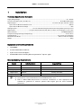
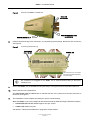
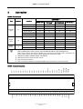
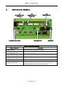
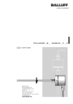
BMB01
Remote I/O Unit
Installation Guide
ASL Document Ref.: U-450-1693.doc
Issue: 02 Complete, Approved - Date: 14/12/09
Part Number: M0450_11
BMB01 – Installation Guide
This equipment is designed and manufactured to conform to the following EC standards:
EMC:
EN55103-1/E1:1996, EN55103-2/E5:1996, EN50121-4:2006, ENV 50204:1995
Safety: EN60065:2002
Failure to use the equipment in the manner described in the product literature will
invalidate the warranty.
A ‘Declaration of Conformity’ statement to the above standards, and a list of auxiliary
equipment used for compliance verification, is available on request.
This product must be disposed of in accordance with the WEEE directive.
Contents
1
Installation..................................................................................................................................................3
2
Connection ..................................................................................................................................................7
3
Controls and Indicators ..............................................................................................................................9
4
Safety and Precautions.............................................................................................................................10
Additional User Documentation:
Additional reference information is available from the ASL website: www.asl-control.co.uk
Copyright © 2009 Application Solutions (Safety and Security) Limited
Application Solutions (Safety and Security) Limited
Unit 17 Cliffe Industrial Estate
Lewes - East Sussex
BN8 6JL - UK
Tel: +44(0)1273 405411
Fax: +44(0)1273 405415
www.asl-control.co.uk
All rights reserved.
Information contained in this document is believed to be accurate, however no representation or warranty is given and Application
Solutions (Safety and Security) Limited assumes no liability with respect to the accuracy of such information.
Issue: 02 Complete, Approved
Page 2 of 12
BMB01 – Installation Guide
1
Installation
Technical Specification Summary
Supply Voltage Range ........................................................................................................................................18 – 40 V DC
Current Consumption (max, all LED’s on)....................................................................................... 70 mA @ 24 V DC supply
Digital Outputs ......................................................................................................... 12 x active-low open-collector outputs
Open-collector Maximum Rated Current ............................................................................................................ 350 mA
Open-collector Maximum Voltage.............................................................................................................................60 V
Analogue Inputs .............................................. 12 x non-isolated analogue interfaces internally pulled up to 5 V by 4.7 kΩ
Digital Inputs.........................................12 x opto-isolated interfaces with built-in resistor to suit voltages of +12 to +40 V
Data Connection................. ..................................................................................................................EIA RS485 9600 baud
Temperature Range (Storage and Operating)................................................................................................-5 °C to +50 °C
Humidity Range........................................................................................................................ 0 % to 93 % non-condensing
Dimensions (H x W x D) ..............................................................................................................105 mm x 156 mm x 58 mm
Weight ..........................................................................................................................................................................300 g
Equipment and Tool Requirements
•
This BMB01.
•
A small flat bladed screwdriver.
•
A pair of wire cutters/strippers.
•
Suitable DIN rail for mounting (35 mm symmetrical “top-hat” type).
External Cabling Requirements
Signals
Cable Description
Data
1 x 2-core twisted, screened
Power
1 x 2-core
Analogue inputs
Suggested Type
Suitably rated foil screened cable
Suitably rated cable
Multicore, screened
Suitably rated foil screened cable
Digital inputs
Multicore
Suitably rated cable
Digital outputs
Multicore
Suitably rated cable
1)
Screened cable must be used for the RS485 data connections and analogue input connections.
2)
The maximum recommended distance for the RS485 data link is 1 km.
3)
Refer to BS7671:2008 (Requirements for Electrical Installations) or other appropriate local
standards for guidelines on maximum potential cable lengths given the actual installation
parameters.
Issue: 02 Complete, Approved
Page 3 of 12
BMB01 – Installation Guide
Recommended Installation Procedure
!
1.
Please read and observe the instructions and guidelines in Section “4 Safety and Precautions”
(page 10) prior to installation. Failure to follow these instructions and guidelines may cause personal
injury and/or damage to the equipment.
If fitted, remove the connectors from both sides of the BMB01; see Figure 1.
Figure 1
!
2.
Removing the connectors
Care must be taken not to bend any pins in the BMB01 unit when removing and inserting
connector blocks. Male and female parts of the blocks must be square to each other at all times.
Remove the lid from the BMB01 by using a small screwdriver to depress the black clips at either side
of the unit and lifting the lid off; see Figure 2.
Figure 2
Removing the BMB01 lid
DEPRESS CLIPS USING A
SMALL SCREWDRIVER.
Issue: 02 Complete, Approved
Page 4 of 12
BMB01 – Installation Guide
3.
Set the Address Switch to the correct number between 1 and 9; see Figure 3.
Figure 3
Address Switch and link locations and settings
LK4
INTERNAL PULL-UP
ENABLE (1-4)
LK5
INTERNAL PULL-UP
ENABLE (5-8)
LK3
TERMINATOR LINK
LINK SETTINGS:
LINK FITTED
LINK OPEN
PROCESSOR HEALTH
LED
ADDRESS SWITCH
COMMS LED
EXAMPLE: ADDRESS SWITCH SET TO 1
Address 0 is not used.
VAR Routers can only use addresses 1 to 6.
4.
If the unit is the last (or only) Remote I/O Unit on the RS485 bus, then fit the Terminator Link (LK3)
over both pins; see Figure 3.
5.
Set the pull-up links (LK4, LK5) as required; see Figure 3.
LK4: fit link to enable internal pull-ups on the anodes of the opto-isolators for Digital Inputs 1 to 4.
LK5: fit link to enable internal pull-ups on the anodes of the opto-isolators for Digital Inputs 5 to 8.
6.
Replace the BMB01 lid, ensuring that it is the correct way round.
The lid on the BMB01 is designed to attach one way only. For this reason the clips on either side
are of different sizes. When re-attaching the lid, ensure that both clips fit their corresponding
hole either side of the lid.
7.
Clip the BMB01 onto the DIN rail by positioning the top of the BMB01’s rear DIN rail mount on the DIN
rail and then pivoting the unit downwards and backwards until the spring loaded clip has fastened;
see Figure 4.
Issue: 02 Complete, Approved
Page 5 of 12
BMB01 – Installation Guide
Figure 4
Attaching the BMB01 to the DIN rail
REAR DIN
RAIL MOUNT
PIVOT DOWNWARDS AND
BACKWARDS
SPRING LOADED CLIP
8.
Connect the field wiring to the connectors, as required by system design. Reconnect each connector;
see Figure 5.
Figure 5
Connecting the field wiring
PROCESSOR
HEALTH LED
COMMS LED
Field wiring shown as an example.
Connections will differ depending
on system design.
The connectors are pluggable so the BMB01 can be replaced without having to disconnect
individual wires.
9.
Secure the BMB01 unit on the DIN rail using end-stop or wiring terminals on both sides of the unit.
10.
Ensure that the unit is powered on.
The PROCESSOR HEALTH LED flashes to indicate that the unit is powered on and the processor is
fault free; see Figure 5.
11.
The installation is now complete and ready for system commissioning.
When the BMB01 is correctly configured and commissioned the LEDs (see Figure 5) flash as follows:
•
PROCESSOR HEALTH LED: flashes approx once per second
•
COMMS LED: flashes very fast
See Section “3 Controls and Indicators” (page 9) for further details.
Issue: 02 Complete, Approved
Page 6 of 12
BMB01 – Installation Guide
2
Connection
BMB01 I/O Functions
Applicability 1)
Type
Quantity
Functions
VAR4/12/20
Intellevac DAU
and VAR8
Intellevac ACU
and VAR8-ACU
VIPA Devices 2)
No
Yes 3) or 4)
No
No
Routing Reset
No
3) or 4)
No
No
3), 5)
Yes
Yes
Yes
Yes
Yes
Yes
No
No
Yes
Yes
No
No
Routing
Analogue
Input
ANS Input
12
3), 5)
Volume Control
Program Selector
Digital
Input
Yes
3) or 4)
Yes 3)
Routing 4)
Yes
Yes
Yes
Yes
Yes
Yes
Yes
No
Yes
Yes
Yes
Yes
No
No
Yes
No
Yes
Yes
No
Yes
No
Yes
Yes
No
4)
External Fault Input
Busy Output
12
1)
Yes
3) or 4)
Yes
Global Silence
Digital
Output
3)
External Fault Input
Routing Reset
12
3), 5)
Yes
4)
4)
3)
Fault Indication
3)
Applicability at the time of the publication of this document for VAR4/12/20 SW V5.3.0523, Intellevac
DAU and VAR8 SW V2.1.0143, Intellevac ACU and VAR8-ACU SW V2.1.0135, VIPA SW V2.12.4.
Some of the functions may not be available if your system has an earlier version of software. For
further details, and for information on other applications, please refer to ASL.
VIPA Devices: VIPET, LINUTOP, iPA400, and iPAM400.
Monitored connection (short and open circuit).
Non-monitored connection.
Refer to Installation Guide for the VC01/PS01/ANS range of products for connection details.
2)
3)
4)
5)
SCREEN
DATA DXN
DATA DXP
0V IN
+24V IN
DI12-
DI11-
DI10-
DI9-
DI(9-12)+
DI8-
DI8+
DI7-
DI7+
DI6-
DI6+
DI5-
DI5+
DI4-
DI4+
DI3-
DI3+
DI2-
AI6
AI7
AI8
AI9
AI10
DO6
+24V OUT
AI5
DO12
AI4
Issue: 02 Complete, Approved
Page 7 of 12
DO11
19 20 21 22 23 24 25 26
DO10
11 12 13 14 15 16 17 18
DO9
10
DO8
9
DO7
8
DO5
7
DO4
6
DO3
5
DO2
4
DO1
3
AI12
2
AI11
1
AI3
45 46 47 48 49 50 51 52
AI2
33 34 35 36 37 38 39 40 41 42 43 44
AI1
29 30 31 32
0V OUT
27 28
DI2 +
DI1-
DI1+
BMB01 Terminal Allocation
BMB01 – Installation Guide
BMB01 Terminal Description
Pin No
Signal
Description / Operation
1
0V OUT
2-13
AI1-AI12
0 V connection for Analogue Inputs
14-25
DO1-DO12
26
+24V OUT
27-42
DI1-DI8
43
DI(9-12)+
44-47
DI9-DI12-
48
+24V IN
49
0V IN
Analogue Inputs (internal 4.7 kΩ pull-up to +5 V)
Digital Outputs (open-collector)
+ve supply (as 24 V in) for open-collector outputs. Resetable internal 1.6 A fused.
Digital Inputs 1 to 8
+ = Opto-anode (with internal 4.7 kΩ pull-up to +5 V enabled/disabled via link settings)
- = Opto-cathode
Common connection to external pull-ups on the anode of the opto-isolators of Digital
Inputs 9 to 12
Digital Inputs 9-12 (opto-cathode)
18-40 V Supply In
0 V Supply In
50
DATA DXP
RS485 DATA +
51
DATA DXN
RS485 DATA -
52
SCREEN
Screen connection for RS485 data
BMB01 Power Connection Options
EXAMPLE SHOWING POWER FROM CENTRAL RACK
CENTRAL RACK
BMB01
+ SUPPLY
24V in
(e.g. V400 or X400 AUX OUT)
0V in
0 V IN
DXP
DXN
DXP
RS 485
DXN
CONNECTOR
CHASSIS 0V
SCREEN
EXAMPLE SHOWING LOCAL POWER
CENTRAL RACK
BMB01
24V in
+
-
LOCAL
ISOLATED
SUPPLY
0V in
0 V IN
DXP
DXN
DXP
DXN
RS 485
CONNECTOR
CHASSIS 0V
SCREEN
!
Power to the BMB01 can either be local or from the central rack equipment.
If a local power supply is used, a 0 V connection must be made between the central rack and the BMB01
for correct operation of the data-link. The local power supply must be isolated from ground to avoid
potentially large ground currents flowing in the 0 V interconnection if the BMB and central rack are an
appreciable distance apart.
If powered from the central rack, the cabling should be selected so that the total load does not cause
excessive voltage drop (>4 V) in the 0 V connection otherwise incorrect operation of the data-link may
occur
Issue: 02 Complete, Approved
Page 8 of 12
BMB01 – Installation Guide
3
Controls and Indicators
LK4
INTERNAL PULL-UP
ENABLE (1-4)
PROCESSOR HEALTH LED
LK5
INTERNAL PULL-UP
ENABLE (5-8)
LK3
TERMINATOR LINK
ADDRESS SWITCH
COMMS LED
BMB01 Controls and Indicators
Control / Indicator
Description
ADDRESS SWITCH
Enables addresses in the range 1 to 9 to be set.
LK3
RS485 TERMINATOR LINK
Link MUST be fitted to the last (or only) BMB01on the RS485 bus in order to
correctly terminate the bus.
LK4
INTERNAL PULL-UP ENABLE (1-4)
Fit link to enable internal pull-ups on the anodes of the opto-isolators for
Digital inputs 1 to 4.
LK5
INTERNAL PULL-UP ENABLE (5-8)
Fit link to enable internal pull-ups on the anodes of the opto-isolators for
Digital inputs 5 to 8.
COMMS LED
Flashes very fast when the unit is transmitting RS485 data.
PROCESSOR HEALTH LED
Flashes slowly (approx once per second) when comms is detected ok.
Flashes fast (approx twice per second) when no comms is detected.
No LED activity indicates processor fault or loss of power.
Issue: 02 Complete, Approved
Page 9 of 12
BMB01 – Installation Guide
4
Safety and Precautions
Environmental
Unpacking and Handling
The equipment should be unpacked and inspected
immediately on receipt. If damage has occurred please
advise your carrier or supplier.
The temperature and humidity ranges shown in the
specifications for this product must not be exceeded.
This equipment must not be installed in an area that is
subject to a corrosive atmosphere, excessive moisture
or may allow water or other liquids to come into contact
with the unit or its external connections.
!
This equipment contains electronic
devices that are sensitive to electrostatic
discharge. Please take precautions to
avoid damage to the electronics by static
electricity.
Electrical Safety
!
Always replace blown fuses with the
correct type and rating. Ensure power
supply cabling is adequately rated.
It is advisable to retain the original equipment packing
in the event that the equipment ever needs returning for
service.
Ensure that the name and address of the Authorised
Distributor from whom you purchased the unit is
recorded on the “Service and Warranty” page of this
manual for future reference.
ESD Precautions
This product contains static-sensitive devices. Observe
ESD precautions when handling this product.
Packing for Return for Repair
!
EMC
In the close proximity of some radio frequency
transmitters, the signal to noise ratio of this product
may be reduced. If this occurs, re-location of the
equipment or the signal cables is recommended.
!
All electronics assemblies must be
properly packed in ESD protective
packing for transport, to prevent physical
and ESD damage.
The filler material used for packing for
return for repair must be antistatic or
static dissipative, as this may come into
contact with exposed connectors, wiring,
or PCB assemblies. The use of nonconductive filler material may cause
damage to the electronic assemblies
reducing their operational life, or even
destroying them.
Advice on packing the product for return can be
provided by ASL.
Issue: 02 Complete, Approved
Page 10 of 12
Notes
Service and Warranty
Name and Address of Authorised Distributor:
This product carries a full warranty. For full details of
warranty and service agreements, please contact the
Authorised Distributor who supplied the product to you.
Exclusions
The warranty does NOT cover:
1.
Customer misuse, including incorrect installation.
2.
Damage other than manufacturing defects.
3.
Transit / Courier damage.
4.
Incorrect voltage or power supply used.
5.
Incorrect input signal.
6.
Abnormal environmental operating conditions.
7.
Damage incurred by accident, fire, lightning or other
hazard.
8.
Modification to the unit or inexpert / attempted
repair.
9.
No fault found – where no fault can be found after
extensive testing, indicating user error or failure in
ancillary equipment.
10.
Electronic assemblies which are improperly packed
when returned for repair or service.
Should any of the above apply, Application Solutions (Safety and Security) Limited reserves the right to raise any relevant charges to
the customer.
Application Solutions (Safety and Security) Limited shall not be liable for any indirect, special or consequential loss or damage
(including without limitation any loss of profits) arising from the use of this product or for any breach of this warranty.
In the interest of continual product development, Application Solutions (Safety and Security) Limited reserves the right to make
changes to product specification without notice or liability.