1
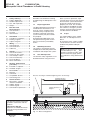
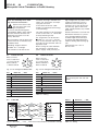
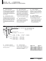
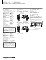
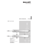
BTL5-S1_ _-M_ _ _ _-P-S32/S147/KA_ _
english
User’s Guide
Balluff GmbH
Schurwaldstrasse 9
73765 Neuhausen a.d.F.
Germany
Phone +49 (0) 71 58/1 73-0
Fax +49 (0) 71 58/50 10
Servicehotline +49 (0) 71 58/1 73-3 70
E-Mail: [email protected]
http://www.balluff.de
BTL5-S1_ _-M_ _ _ _-P-S32/S147/KA_ _
Micropulse Linear Transducer in Profile Housing
Contents
1
1.1
1.2
1.3
1.4
Safety Advisory .................... 2
Proper application ................. 2
Qualified personnel ............... 2
Use and inspection ............... 2
Scope ..................................... 2
2
Function and
Characteristics ..................... 3
2.1 Characteristics ...................... 3
2.2 Function ................................. 3
2.3 SSI interface .......................... 3
3
3.1
3.2
3.3
Installation ............................ 4
Transducer installation .......... 4
Floating magnets ................... 5
Captive magnets ................... 5
4
4.1
4.2
4.3
Wiring .................................... 6
Connector S32 ....................... 6
Connector S147 ..................... 6
Cable KA_ _ .......................... 6
5
5.1
5.2
5.3
5.4
5.5
5.6
Startup .................................. 7
Check connections ................ 7
Turning on the system ........... 7
Check output values ............. 7
Check functionality ................ 7
Fault conditions ..................... 7
Noise elimination ................... 7
1
Safety Advisory
Read this manual before installing
and operating the Micropulse Transducer.
1.1
Proper application
The BTL5 Micropulse transducer is
intended to be installed in a machine or system. Together with a
controller (PLC) or a processor it
comprises a position measuring
system and may only be used for
this purpose.
Unauthorized modifications and
non-permitted usage will result in
the loss of warranty and liability
claims.
1.2
ducer system. In particular, steps
must be taken to ensure that should
the transducer system become defective no hazards to persons or
property can result. This includes
the installation of additional safety
limit switches, emergency shutoff
switches and maintaining the permissible ambient conditions.
1.4
This guide applies to the model
BTL5-S1...P... Micropulse transducer.
An overview of the various models
can be found in section 6 Versions
(indicated on product label) on
page 7.
Qualified personnel
This guide is intended for specialized personnel who will perform the
installation and setup of the system.
1.3
Scope
Use and inspection
The relevant safety regulations must
be followed when using the trans-
Note: For special versions, which
are indicated by an -SA_ _ _ designation in the part number, other
technical data may apply (affecting calibration, wiring, dimensions
etc.).
6
Versions (indicated on
part label) .............................. 7
6.1 Included in shipment ............. 7
6.2 Available lengths ................... 7
8
Technical Data ...................... 9
8.1 Dimensions, weights,
ambient conditions ................ 9
8.2 Supply voltage ...................... 9
8.3 Control signals ....................... 9
8.4 Connection to processor ....... 9
Notch on housing to mark the beginning of the stroke range
Nominal stroke =
Measuring range
Moving machine part
Current position of
magnet
Micropulse Transducer
The following patents have been
granted in connection with this
product:
US Patent 5 923 164
Apparatus and Method for Automatically Tuning the Gain of an
Amplifier
2
english
Machine
Fig. 1-1: Basic arrangement
Damping zone
Accessories .......................... 8
Magnets ................................. 8
Connector .............................. 8
Compatible devices .............. 8
Connecting rod ...................... 8
El. connection
7
7.1
7.2
7.3
7.4
BTL5-S1_ _-M_ _ _ _-P-S32/S147/KA_ _
Micropulse Linear Transducer in Profile Housing
2
Function and Characteristics
2.1
Characteristics
Micropulse transducers feature:
– High data security: Output data
are checked for validity and plausibility in the µC
– Very high resolution, repeatability
and linearity
– Measurement range monitoring
with "Out of Range" Bit 221
– Immunity to shock, vibration, and
contamination
– An absolute output signal
– Wear- and maintenance-free
– BTL to processor cable lengths
up to 400 m
– IP 67 per IEC 60529
2.2
Dimensions for installing the
Micropulse transducer and for the
magnets and control arm are found
on ➥ page 5.
The magnet defines the measured
position on the waveguide. An
internally generated INIT pulse
interacts with the magnetic field of
the magnet to generate a magnetostrictive torsional wave in the
waveguide which propagates at
ultrasonic speed.
2.3
Depending on the BTL version, the
SSI interface uses 24 or 25 bits
and the position values are transmitted in Gray or binary code.
Transmission of the position values
is finished in time tm. The max.
clock frequency t depends on the
cable length ➥ section 8 Technical
Data on page 9.
The torsional wave arriving at the
end of the waveguide is absorbed in
the damping zone. The wave arriving at the beginning of the waveguide creates an electrical signal in
the coil surrounding the waveguide.
The corresponding value is output
as synchronous serial data (SSI) via
the RS 485/422 interface. This
takes place with high precision
and repeatability within the measuring range indicated as the
nominal stroke length.
Function
The Micropulse transducer contains
a waveguide enclosed by an extruded aluminum housing. A magnet attached to the moving member of the machine is moved
across the top of the housing and
its position constantly updated.
SSI interface
Bit 221 can be used as an "Out-ofRange" message, see Figs. 2-1
and 2-2.
Sending of the position values is
finished within time tm. It is started
with the falling edge of the last
clock pulse. After this time the
BTL is ready for the next data
transmission.
On both ends of the nominal
stroke length is an area which provides an unreliable signal, but
which may be entered.
The electrical connection between
the transducer, the processor/controller and the power supply is via a
cable, which is connected using a
female connector.
Clock sequence
t < tm
tv = 150 ns
tm = 31 µs
measured with 1 m cable
independent of the clock
frequency
The time tm starts with the falling edge of
the last clock impulse (bit 24 or bit 25
depending on the version).
➀
Fig. 2-1: Pulse diagram, example with 24 bit coding
➀ only by an resolution of > 5 µm
Null point
1a
2
3
End point
2
1b
Position of magnet:
1) out of the measurement range
2) within the measurement range
3) magnet not present
"Out of Range" Bit 221 will be set
after the occurence of the event.
Value of the output data 20 ... 220:
1a) 0
1b) max. at end point + 10 mm
2) proportional to distance
3) 0
Technical data are valid within the
measurement range only, i.e. between
null and end point.
21
Bit 2
~10 mm
~10 mm
Bit 20... 220
Fig. 2-2: Output data shown with "Out of Range" situation
english
3
BTL5-S1_ _-M_ _ _ _-P-S32/S147/KA_ _
Micropulse Linear Transducer in Profile Housing
3
Installation
3.1
Transducer installation
A sufficient quantity of mounting
brackets is supplied.
Ensure that no strong electrical
or magnetic fields are present in
the immediate vicinity of the
transducer.
Recommended installation:
Distance A = approx. 80 mm
Distance B = approx. 250 mm (between the individual clamps)
Any orientation is permitted.
To prevent resonant frequencies
under vibration loads of >50 g, we
recommend placing the mounting
clamps at irregular intervals.
The supplied mounting brackets
and cylinder head screws allow the
transducer to be mounted on a flat
machine surface.
➀
The supplied isolation bushings
are used to electrically insulate the
transducer from the machine
➥ Fig. 3-1 respectively 3-2 and
(➥
chapter 5.6 Noise elimination).
The Micropulse transducer in profile housing is suitable both for
floating, i.e. non-contacting mag➥ page 5) and for captive
nets (➥
➥ page 5).
magnets (➥
➀
NL
Nominal stroke
BTL5...P-S32/S147
Mounting brackets with isolation bushings
and M5 × 22 cylinder head screws, DIN 912,
max. tightening torque 2 Nm
➀ unusable area
Fig. 3-1: Dimensional drawing (BTL5...P-... transducer with floating magnet BTL5-P-3800-2)
➀
NL
Nominal stroke
BTL5...P-KA...
➀
Magnet
Black,
round
marking
Mounting brackets with isolation bushings
and M5 × 22 cylinder head screws, DIN 912,
max. tightening torque 2 Nm
Fig. 3-2: Dimensional drawing (BTL5...P-... transducer with captive magnet BTL5-F-2814-1S)
4
english
BTL5-S1_ _-M_ _ _ _-P-S32/S147/KA_ _
Micropulse Linear Transducer in Profile Housing
Installation (cont.)
3.2
Floating magnets
Magnet type
➥ Figs. 3-3 to
The floating magnet (➥
3-5) is attached to the moving
member of the machine using nonmagnetizable screws (brass, aluminum). To ensure the accuracy of
the transducer system, the moving
member must carry the magnet on a
track parallel to the transducer.
The following table provides figures
in [mm] for the spacing which must
be maintained between magnet and
transducer and for the permissible
center offset:
➀
Fig. 3-3: BTL5-P-3800-2 magnet
Distance
"D"
0.1 ... 4
Offset
"C"
±2
BTL5-P-5500-2
5 ... 15
± 15
BTL5-P-4500-1
0.1 ... 2
±2
BTL5-P-3800-2
BTL5-P-4500-1 magnet, special
features: Multiple magnets on the
same transducer can be
electricely turned on and off individually (PLC control signal, 24 V/
100 mA).
The stroke range is offset 4 mm
towards the BTL connector/cable
(➥ Fig. 3-5).
Ensure that the distance
E between parts made of
magnetizable material and
the BTL5-P-5500-2 magnet is at
least 10 mm (➥ Fig. 3-4).
max. permissible
tightening torque 2 Nm
Connector
with LED
3
Fig. 3-4: BTL5-P-5500-2 magnet
➀
Fig. 3-5: BTL5-P-4500-1
➀
➀ not included
3.3
Captive magnets
Lateral forces are to be avoided
when using captive magnets
➥ Figs. 3-6 and 3-7). Connections
(➥
are required here which permit the
corresponding degree of freedom
Ball joint "B"
DIN 71805,
rotates horizontally
Black, round
marking
with respect to the direction of
movement of the magnet along the
stroke range. It is assumed that
the BTL5-F-2814-1S magnet is
connected to the machine member
using a connecting rod.
Mechanically joined to M5
stud using 2 nuts
BTL5-M-2814-1S
BTL5-N-2814-1S
Fig. 3-6: BTL5-F-2814-1S magnet ➀
The BTL2-GS10...A connecting rod
➥ Fig. 7-2) is available as an ac(➥
cessory (please indicate length LG
when ordering).
X
48.5
51
Max. angle offset
Max. parallel offset
Y
57
59.5
Fig. 3-7: BTL5-M/N-2814-1S magnet ➀
english
5
BTL5-S1_ _-M_ _ _ _-P-S32/S147/KA_ _
Micropulse Linear Transducer in Profile Housing
4
Wiring
Note the following when making electrical connections:
System and control cabinet must be at the same
ground potential.
To ensure the electromagnetic
compatibility (EMC) which Balluff
warrants with the CE Mark, the
following instructions must be
strictly followed.
BTL transducer and the processor/
control must be connected using
shielded cable.
Shielding: Copper filament
braided, 85 % coverage.
The shield must be tied to the
4.1
Connector S32
connector housing in the BKS connector; see instructions accompanying the connector.
In the cable version the cable
shield is connected to the housing
in the PG fitting.
The cable shield must be grounded
on the control side, i.e., connected
to the protection ground.
Pin assignments can be found in
➥ Table 4-1, 4-2 or 4-3. Connections on the controller side may vary
according to the controller and configuration used.
When routing the cable between
the transducer, controller and
power supply, avoid proximity to
4.2
high voltage lines to prevent noise
coupling. Especially critical is
inductive noise caused by AC
harmonics (e.g. from phase-control devices), against which the
cable shield provides only limited
protection.
Position information is sent over the
RS 485/422 interface as synchronous serial data (SSI) to the host
controller. High noise immunity is
assured by the differential drivers
used for sending and receiving signals.
Cable length max. 400 m;
Ø 6 to 8 mm.
Connector S147
BKS Connector,
View of solder end
of connector body
BKS-S32M-00
or BKS-S33M-00
BKS Connector,
View of solder end
of connector body
BKS-S147M-00 or
BKS-S148M-00
Fig. 4-1: Pin arrangement BKS on BTL
Fig. 4-2: Pin arrangement BKS on BTL
Pin
BTL5-S1_ _...S32
Interface signals
1
+Clk
2
+Data
3
–Clk
4
do not connect
5
–Data
Supply voltage (external)
6
GND
7
+24 V
8
do not connect
Pin
BTL5-S1_ _...S147
Interface signals
1
–Data
2
+Data
3
+Clk
4
–Clk
Supply voltage (external)
5
+24 V
6
GND
7
do not connect
Caution! False data will result
from reversing the +Clk and –Clk
inputs.
Table 4-2: Wiring
Table 4-1: Wiring
4.3
Cable KA_ _
BTL5-S1_ _
+Clk
YE
–Clk
PK
+Data
GY
–Data
GN
GND
BU
+24 V
BN
Processor/
Controller
Fig. 4-3: BTL5-S1_ _-...KA_ _ with Processor/Controller, Connection example
6
english
Colors
BTL5-S1_ _...-KA_ _
Interface signals
YE yellow
+Clk
PK ping
–Clk
GY gray
+Data
GN green
–Data
Supply voltage (external)
BU blue
GND
BN brown
+24 V
WH white
do not connect
Table 4-3: Wiring
BTL5-S1_ _-M_ _ _ _-P-S32/S147/KA_ _
Micropulse Linear Transducer in Profile Housing
5
Startup
5.1
Check connections
5.3
Check output values
5.5
Fault conditions
Although the connections are polarity reversal protected, components
can be damaged by improper connections and overvoltage. Before
you apply power, check the connections carefully.
After replacing or repairing a transducer, it is advisable to verify the
values for the start and end position
of the magnet in manual mode. If
values other * than those present
before the replacement or repair are
found, a correction should be made.
When there is evidence that the
transducer system is not operating
properly, it should be taken out of
service and guarded against unauthorized use.
5.2
* Transducers are subject to modification or manufacturing tolerances.
Any difference in potential - current
flow - through the cable shield
should be avoided. Therefore:
– Use the isolation bushings, and
– Make sure the control cabinet
and the system in which the
BTL5 is contained are at the
same ground potential.
Turning on the system
Note that the system may execute
uncontrolled movements when first
turned on or when the transducer is
part of a closed-loop system whose
parameters have not yet been set.
Therefore make sure that no hazards could result from these situations.
6
5.4
Check functionality
The functionality of the transducer
system and all its associated components should be regularly
checked and recorded.
5.6
Noise elimination
Versions (indicated on part label)
Supply voltage: 1 = DC 24 V
Electr. connection, S32: with connector, 8 pin
S147: with connector, 7 pin
KA05: with 5 m cable
SSI interface
Micropulse
Linear Transducer
BTL5-S102-M0450-P-S32
Profile form factor
Nom. length (4digits):
Resolution: 1 = 1 µm
5 = 40 µm
Code: 24 bit 0
2
25 bit 6
8
6.1
=
=
=
=
binary,
binary,
binary,
binary,
Included in shipment
Transducer with condensed guide
Mounting brackets
M = metric in mm
2 = 5 µm
6 = 100 µm
rising
falling
rising
falling
6.2
1
3
7
9
=
=
=
=
3 = 10 µm
7 = 2 µm
Gray,
Gray,
Gray,
Gray,
4 = 20 µm
8 = 50 µm
rising
falling
rising
falling
Available lengths
To ensure flexible application,
nominal transducer lengths of from
50 to 4000 mm with following increments are available:
Stroke lengths
[mm]
50 ... 1000
1000 ... 2000
2000 ... 4000
Increments
[mm]
50
100
250
Other stroke lengths on request.
english
7
BTL5-S1_ _-M_ _ _ _-P-S32/S147/KA_ _
Micropulse Linear Transducer in Profile Housing
7
Accessories (order separately)
7.1
Magnets
7.2
Regarding distance, offset, and
dimensions see ➥ pages 4 and 5.
Operating temp. –40 to +85 °C
➥ Fig. 3-3
BTL5-P-3800-2
Weight
approx. 12 g
Housing
plastics
BTL5-F-2814-1S ➥ Fig. 3-6
Weight
approx. 28 g
Housing
plastics
BTL5-M-2814-1S ➥ Fig. 3-7
Weight
approx. 32 g
Housing
aluminum,
anodized
Sliding surface
plastics
BTL5-N-2814-1S ➥ Fig. 3-7
Weight
approx. 35 g
Housing
aluminum,
anodized
Sliding surface
plastics
Connector
straight
BKS-S147M-00
7.3
right-angle
BKS-S148M-00
Cable entry
(PG 9 fitting)
BTL5-P-5500-2 and
BTL5-P-4500-1:
Recommended
resolutions
20 µm or 40 µm
< ± 100 µm
Non-linearity
The stated non-linearity of
< ± 100 µm is valid when guided
exactly with a constant gap from
the profile within the permissible
distance "D".
8
english
Connecting rod
BTL2-GS10-_ _ _ _-A
Aluminum, dimensions ➥ Fig. 7-2
Various standard lengths LG available (please specify when ordering)
straight
BKS-S32M-00
right-angle
BKS-S33M-00
No. 99-5672-19-08
Binder Corp.
No. 99-5672-78-08
Ball joint "B" DIN 71805, rotates horizontally (part of BTL5-F-2814-1S
magnet) magnet)
Jam nut DIN 934 M5
The stated non-linearity of
± 30 µm is valid when guided
exactly with a constant gap from
the profile within the permissible
distance "D".
➥ Fig. 3-4
approx. 40 g
plastics
➥ Fig. 3-5
approx. 80 g
plastics
-40 °C to +60 °C
Display:
BDD-AM10-1-SSI
display and limit controller
with 2 relay outputs
7.4
BTL5-P-3800-2 and
BTL5-F/M/N-2814-1S:
BTL5-P-5500-2
Weight
Housing
BTL5-P-4500-1
Weight
Housing
Operating temp.
Compatible devices
Swivel eye DIN 648
Fig. 7-2: Connecting rod
Fig. 7-1: Connector
BTL5-S1_ _-M_ _ _ _-P-S32/S147/KA_ _
Micropulse Linear Transducer in Profile Housing
8
Technical Data
The following are typical values at DC 24 V and room temperature. Fully operational after power-up, with full accuracy after warm-up. Values are with BTL5-P-3800-2, BTL5-P-4500-1 or BTL5-P-5500-2 magnet held at a constant
offset from the transducer or with captive magnet BTL5-F/M/N-2814-1S (see magnet section for exceptions):
Non-linearity
for resolution < 10 µm
for resolution > 10 µm
Output data
Update rate fmax
< 4000 mm
➥ page 4
approx. 1.4 kg/m
anodized
aluminum
Housing attachment
Mounting clamps with isolation
bushings and screws
Operating temp. –40 °C to +85 °C
Humidity < 90%, non-condensing
Protection class per IEC 60529
IP 67 when closed up
Nominal length
Dimensions
Weight
Housing
± 30 µm
± 2 LSB
< 2 kHz
8.2
< 1 LSB
Hysteresis
< 2 LSB
Repeatability
(resolution + hysteresis)
Temperature coefficient
(6 µm + 5 ppm * nominal length)/K
Shock loading
100 g/6 ms
per IEC 60068-2-27 1
Continuous shock
100 g/2 ms
per IEC 60068-2-29 1
Vibration 12 g, 10 to 2000 Hz
per IEC 60068-2-6 1
1
Dimensions, weights,
ambient conditions
Supply voltage (external)
Regulated supply voltage
BTL5-S1...
DC 20 to 28 V
< 0.5 Vpp
Ripple
Current draw
< 90 mA
< 3 A/0.5 ms
Inrush
Polarity reversal protection built-in
Overvoltage protection
Transzorb diodes
Electric strength
GND to housing 500 V
8.3
Control signals
IInterface
RS 485/422
Clock input
+Clk, –Clk
(via optical coupler)
Clock frequency max. 1000 kHz
Output data
24 or 25 bit serial
Position information +Data, –Data
8.4
Connection to processor
+Clk, –Clk, +Data, –Data, 24 V,
GND
Cable, twisted-pair, shielded
max. length 400 m, Ø 6 to 8 mm
The clock frequency t is a function
of the cable length:
Cable length
< 25 m
< 50 m
< 100 m
< 200 m
< 400 m
Clock frequency
< 1000 kHz
< 500 kHz
< 400 kHz
< 200 kHz
< 100 kHz
Table 8-1: Clock frequency
Individual specifications as per
Balluff factory standard
UL authorization
File No.
E227256
The CE Mark verifies
that our products meet
the requirements of
EC Directive
89/336/EEC (EMC Directive)
and the EMC Law. Testing in our
EMC Laboratory, which is accredited by DATech for Testing Electromagnetic Compatibility, has confirmed that Balluff products meet
the EMC requirements of the following Generic Standards:
EN 61000-6-4 (emission)
EN 61000-6-2 (noise immunity)
Emission tests:
RF Emission
EN 55011 Group 1, Class A+B
Noise immunity tests:
Static electricity (ESD)
EN 61000-4-2
Severity level 3
Electromagnetic fields (RFI)
EN 61000-4-3
Severity level 3
Fast transients (Burst)
EN 61000-4-4
Severity level 3
Surge
EN 61000-4-5
Severity level 2
Line-induced noise induced by
high-frequency fields
EN 61000-4-6
Severity level 3
Magnetic fields
EN 61000-4-8
Severity level 4
english
9
No. 846 081 - 726 E • 00.000000 • Edition 0510; specifications subject to changes.
8.1
Resolution (LSB)
depending on version:
BTL5-S1_1...
1 µm
BTL5-S1_2...
5 µm
BTL5-S1_3...
10 µm
BTL5-S1_4...
20 µm
BTL5-S1_5...
40 µm
BTL5-S1_6...
100 µm
BTL5-S1_7...
2 µm
BTL5-S1_8...
50 µm