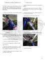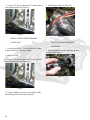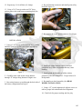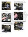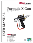
1
2007
American IronHorse®
6
MAINTENANCE 1
6
CHASSIS 2
6
DRIVE 3
6
ENGINE 4
6
ELECTRICAL 5
6
FUEL SYSTEM 6
6
TRANSMISSION 7
6
APPENDIX 8
Texas Chopper
SERVICE
MANUAL
The information in the
manual applies to the
2007 TX. Chopper model
only.
Copyright 2006
American IronHorse®
Motorcycle Company
P/N: A99001307
1
The American IronHorse® Technical Writing Department strives to give our customers a quality product
and quality publications to maintain our product. To accomplish this goal, we need user feedback - your
evaluation of this service and parts manual.
Please provide your comments on this manual. Is this manual complete, and easy to use? Is this manual
accurate?___________________________________________________________
____________________________________________________________________________
____________________________________________________________________________
____________________________________________________________________________
Did you find errors in this manual?________________________________________________
____________________________________________________________________________
____________________________________________________________________________
____________________________________________________________________________
What can we do to improve this manual?____________________________________________
____________________________________________________________________________
____________________________________________________________________________
____________________________________________________________________________
Occupation:______________________________________________________
Name:__________________________________________________________
Dealership:______________________________________________________
Street:__________________________________________________________
City:__________________________State:____________Zip Code_________
Clip out and mail to:
American IronHorse® Motorcycle Company
Technical Writing Department
4600 Blue Mound Rd.
Ft. Worth TX, 76106
2
FORWARD
The American IronHorse® 2007 Parts and Service Manual has been created for two reasons. First, it will
familiarize the technician with construction of the American IronHorse motorcycles and second, guide them
through approved maintenance and repair procedures. We at American IronHorse are certain that this service
and repair manual will increase your shop turn around time and customer satisfaction.
SERVICE PREPARATION
It is imperative that the proper preparation for service be conducted before beginning a repair procedure.
Ensure that all work areas are clean, this will aid in reducing repair time and will reduce the chance of
misplacing tools and/or parts. Any required tools or materials should be gathered before beginning a repair
procedure.
SERVICE/TECHNICAL BULLETINS
From time to time, service and/or technical bulletins may be issued from American IronHorse. These bulletins
can be the result of an engineering change or serviceability change made at the factory. Please consult service/
technical bulletins before beginning a repair procedure in order to ensure the latest information is being used in
the repair procedure.
REPLACEMENT PARTS
When performing any maintenance or repair procedure use only American IronHosre approved parts. Failure
to use American IronHorse approved parts may result in product malfunction and possible serious injury or
death.
PRODUCT REFERENCES
Loctite® Products listed are used to increase the effectiveness of fasteners.
For further questions regarding Loctite® products please contact the Henkel/Loctite Corporation.
Henkel Corp - Industrial
1001 Trout Brook Crossing
Rocky Hill, CT 06067
Phone: 860.571.5100
3
WARNINGS AND CAUTIONS
Statements preceded by the word WARNING or CAUTION printed in bold or italic face are extremely
important.
WARNING means there is potential or personal injury to yourself or others.
CAUTION means there is potential for damage to vehicle or parts.
PLEASE TAKE SPECIAL NOTE OF THESE WARNINGS AND CAUTIONS.
4
MOTORCYCLE SPECIFICATIONS:
Texas Chopper
DIMENSIONS (inches):
Wheel Base:
Overall Length:
Overall Width:
Overall Height:
Ground Clearance:
Seat Height:
84
110.50
35.50
54.75
4.25
25.25
WEIGHT (pounds):
Weight:
GVWR:
GAWR - Front:
GAWR – Rear:
722
1200
490
710
TIRES:
Front:
Rear:
90/90-21
280/35VR-18
WHEELS:
Front:
Rear:
21” x 2.15”
18” x 10.5”
TORQUE SPECIFICATIONS:
APPLICATION
THREAD TREATMENT
TORQUE
Fork Cap
Fork Neck Stem
Triple Tree Pinch
Front Axle
Front Axle Pinch
Ignition, Housing to Mount
Riser to Triple Tree
Upper Bar/Lower Bar pinch
Motor Mounts
DRY
Red Loctite® 262 (17 drops)
Blue Loctite® 243 (2 drops)
Blue Loctite® 243 (4 drops)
Blue Loctite® 243 (2 drops)
Blue Loctite® 243 (1 drop)
Blue Loctite® 243 (1 drop)
Blue Loctite® 243 (2 drops)
Blue Loctite® 243 (3 drops)
50 ft. lbs.
80 ft. lbs.
25 ft. lbs.
55 ft. lbs.
25 ft. lbs
140 in. lbs.
50 ft. lbs.
25 ft.lbs.
45 ft.lbs.
5
TORQUE SPECIFICATIONS (CONT):
APPLICATION
THREAD TREATMENT
Inner Primary to Eng/Trans
Mechanical Fold Tab Lock
Blue Loctite® 243 (2 drops)
Outer Primary/Inner Primary Blue Loctite® 243 (1 drop)
Brake Caliper
Blue Loctite® 243 (3 drops)
Rear Axle
Blue Loctite® 243 (10 drops)
Compensator
Red Loctite® 262 (17 drops)
Clutch Hub Mainshaft
Red Loctite® 262 (17 drops)
Forward Controls
Blue Loctite® 243 (3 drops)
Shocks
Red Loctite® 262 (5 drops)
Transmission Mount
Anti-seize Copper
Transmission Side Cover
Blue Loctite® 243 (1 drop)
Kick Stand
Blue Loctite® 243 (2 drops)
Oil Filter Housing
Blue Loctite® 243 (2 drops)
Starter
Blue Loctite® 243 (2 drops)
Horn
Blue Loctite® 243 (2 drops)
Brake Banjo
DRY
Caliper Bridge Bolts
Blue Loctite® 243 (2 drops)
Hub Bolts
Blue Loctite® 243 (2 drops)
Pulley Bolts
Blue Loctite® 243 (2 drops)
Rear Fender bolts
Blue Loctite® 243 (2 drops)
TORQUE
25 ft. lbs.
140 in. lbs.
40 ft. lbs.
65 ft. lbs.
150 ft.lbs.
75 ft. lbs.
45 ft. lbs
70 ft. lbs.
55 ft. lbs.
10 ft. lbs.
25 ft. lbs.
20 ft. lbs.
20 ft. lbs.
10 ft. lbs.
10 ft. lbs.
28 ft. lbs.
50 ft. lbs.
50 ft. lbs.
40 ft. lbs.
VEHICLE IDENTIFICATION NUMBER:
GENERAL:
The full 17 digit vehicle identification number is located on the right hand side of the neck tube (See Figure 1)
Figure 1
6
Using the example below (Figure 2) the short V.I.N. is abbreviated to 6 digits: SZ6355.
When ordering parts you may use a short V.I.N.
Figure 2
Transmission:
1= R/H Drive
Engine Size:
44= 111
55= 117
66= 124
Model Year:
7= 2007
Sequential Number:
355= 355th bike built in that model
7
Table of Contents
REAR BELT DEFLECTION:
REPLACING AIR FILTER
BATTERY MAINTENANCE:
16
INSPECTION
16
CHARGING:
16
INSTALLATION
REMOVAL:
16
16
ENGINE OIL:
16
CHANGING ENGINE OIL:
16
PRIMARY CHAIN:
17
FREE PLAY ADJUSTMENT
PRIMARY CHAIN INSPECTION
17
17
CHAINCASE LUBRICANT:
17
LUBRICATION AND ADJUSTMENT
17
CLUTCH ADJUSTMENT (HYDRAULIC): 17
TRANSMISSION LUBRICANT:
CHANGING LUBRICANT
FRONT BEARING REMOVAL
INSTALLATION
REAR BEARING INSTALLATION
FRONT WHEEL:
INSTALLATION
REMOVAL
REAR WHEEL:
INSTALLATION
REMOVAL (SY, SC, SJ)
REMOVAL (TX)
TIRES:
INSTALLATION
REMOVAL
FRONT FORK OIL:
CHANGING OIL
BRAKES:
18
18
18
18
19
19
19
19
20
20
20
20
21
21
21
22
22
22
BLEEDING BRAKES
22
BRAKE FLUID INSPECTION
22
REPLACING FRONT CALIPER PADS
23
REPLACING REAR CALIPER PADS
22
8
FUEL FILTER:
FUEL FILTER REPLACEMENT
THROTTLE CABLES:
LUBRICATION AND ADJUSTMENT
24
24
24
25
25
25
ENGINE MOUNTS:
25
INSPECTION
25
SPARK PLUGS:
REPLACING SPARK PLUGS
25
HEADLAMP
25
INSPECTION
25
ADJUSTMENT
26
FRONT WHEEL:
INSTALLATION
REMOVAL
REAR WHEEL:
INSTALLATION
REMOVAL (SY, SC, SJ)
REMOVAL (SZ, TX)
INSTALLATION
TIRES:
INSTALLATION
REMOVAL
FRONT BRAKE MASTER CYLINDER:
ASSEMBLY
CLEANING AND INSPECTION
DISASSEMBLY
REMOVAL
29
29
29
31
31
31
31
32
32
32
32
33
34
34
33
33
REAR BRAKE MASTER CYLINDER:
35
ASSEMBLY
CLEANING AND INSPECTION:
DISASSEMBLY
INSTALLATION
REMOVAL
35
35
35
35
35
FRONT BRAKE CALIPER:
ASSEMBLY
CLEANING AND INSPECTION
DISASSEMBLY
INSTALLATION
REMOVAL
REAR BRAKE CALIPER:
ASSEMBLY
CLEANING AND INSPECTION
DISASSEMBLY
INSTALLATION:
REMOVAL
36
37
36
36
37
36
AIR RIDE SUSPENSION:
INSTALLATION
SEAT:
40
41
40
41
42
45
45
45
43
48
49
50
INSTALLATION
REMOVAL
50
50
KICKSTAND:
50
BELT GUARD:
51
INSTALLATION
REMOVAL
FORWARD CONTROLS:
INSTALLATION
REMOVAL
HANDLE BAR ASSEMBLY:
INSTALLATION
REMOVAL
60
INSTALLATION
REMOVAL
PRIMARY CHAINCASE:
40
ASSEMBLY
BEARING AND RACE REMOVAL
INSTALLATION
REMOVAL
REAR FENDER:
39
38
38
39
37
FRONT FORK LEGS:
TRIPLE TREE:
59
SWING ARM:
39
51
51
52
52
52
54
55
54
HYDRAULIC CLUTCH:
56
REMOVAL
56
INSTALLATION
58
59
REMOVAL
37
BLEEDING BRAKES:
DISASSEMBLY
LOWER LEG ASSEMBLY
REMOVAL:
UPPER LEG ASSEMBLY
OIL TANK:
INSTALLATION
REMOVAL
60
60
60
61
61
65
INSTALLATION CLUTCH ASSEMBLY:
69
INSTALLATION INNER PRIMARY
CHAINCASE
68
INSTALLATION JACKSHAFT
ASSEMBLY
68
INSTALLATION OUTER PRIMARY
CHAINCASE
70
INSTALLATION PRIMARY CHAIN
ASSEMBLY:
69
REMOVAL CLUTCH ASSEMBLY
65
REMOVAL INNER PRIMARY
CHAINCASE
67
REMOVAL JACKSHAFT ASSEMBLY
67
REMOVAL OUTER PRIMARY
CHAINCASE COVER
65
TRANSMISSION BELT GUARD:
INSTALLATION
REMOVAL
TRANSMISSION OUTER COVER:
INSTALLATION
REMOVAL
TRANSMISSION PULLEY:
INSTALLATION
REMOVAL
DRIVE BELT:
INSPECTION
INSTALLATION
REMOVAL
REAR WHEEL PULLEY:
INSPECTION
INSTALLATION
REMOVAL
71
71
71
71
71
71
72
72
72
73
75
75
73
77
78
78
77
9
ROCKER BOX:
INSTALLATION
REMOVAL
CYLINDER HEAD:
INSTALLATION
REMOVAL
CYLINDER and PISTONS:
REMOVAL
PISTONS:
INSTALLATION
REMOVAL
PUSHRODS:
INSTALLATION
REMOVAL
TAPPET BLOCKS AND TAPPETS:
INSTALLATION
REMOVAL
CAM:
83
CIRCUIT BREAKER:
107
83
83
INSTALLATION
REMOVAL
REMOVAL
108
107
107
85
85
85
86
86
87
87
87
90
91
91
92
92
92
93
CAM GEAR MEASURING
CAM INSPECTION
INSTALLATION
REMOVAL
OIL PUMP:
93
93
94
93
94
INSTALLATION
95
COMPRESSION RELEASES:
95
INSTALLATION
REMOVAL (Engine in Frame)
REMOVAL (Engine out of Frame)
COIL:
99
INSTALLATION
REMOVAL
CRANK SENSOR:
INSTALLATION
REMOVAL
IGNITER:
INSTALLATION:
REMOVAL
RHC:
100
99
101
103
101
104
105
104
105
INSTALLATION
REMOVAL
10
96
95
96
106
105
VOLTAGE REGULATOR:
INSTALLATION
REMOVAL
CARBURETOR:
ASSEMBLY
CARBURETOR TESTING AND
TUNING
INSTALLATION
PRE-START CHECKS:
REMOVAL
MANIFOLD:
INSTALLATION
REMOVAL
109
110
109
117
118
121
120
121
117
122
123
122
CHOPPER STYLE TANK FUEL PETCOCK:
124
INSTALLATION
REMOVAL
FUEL LINES:
INSTALLATION
REMOVAL
FUEL FILTER:
INSTALLATION
REMOVAL
CHOPPER STYLE FUEL TANK:
INSTALLATION
REMOVAL
TRANSMISSION BELT GUARD:
INSTALLATION
REMOVAL
TRANSMISSION OUTER COVER:
INSTALLATION
REMOVAL
TRANSMISSION PULLEY:
INSTALLATION
REMOVAL
TRANSMISSION:
INSTALLATION
REMOVAL
124
124
125
125
125
125
125
125
126
126
126
130
130
130
130
130
130
130
131
130
132
133
132
SHIFT LINKAGE:
INSTALLATION
REMOVAL
SHIFT PAWL:
ADJUSTMENT
139
139
139
139
139
11
6
12
MAINTENANCE 1
REGULARLY SCHEDULED MAINTENANCE:
GENERAL
The following procedures are considered to be regularly scheduled
maintenance. Refer to regularly scheduled maintenance table (Fig. 1) for actual
mileages. Performing the following procedures at specified intervals greatly
reduces excessive wear and tear on motorcycle. The regularly scheduled
maintenance table is a reference tool only. If problems are identified before
actual mileages, they should be addressed immediately. It is the owner’s
responsibility to keep current on regularly scheduled maintenance. In the
event a malfunction occurs, regularly scheduled maintenance records may
be used to determine if owner was at fault by not having motorcycle properly
serviced.
13
Odometer Reading
Engine Oil
Oil Filter
Oil Screen
Rear Belt
Primary Chain
Primary Lubricant
Brake Pads and Disc
Brake Fluid Levels
Lights and Horn
Clutch Adjustment
Fuel Valve and Lines
Front Brake Lever
All Fasteners
Tire Pressure / Damage
Engine Idle
Throttle Operation
Electrical Switches
Ignition Timing
Spark Plugs
Transmission Lubricant
Engine Mounts
Rear Brake Caliper
Front Brake Caliper
Sealed Bearings
Front Fork Oil
500
R
R
I
I
I
R
I
I
I
I
I
L
T
I
I
I
I
I
R
I
I
I
-
2000
R
R
I
I
I
I
I
I
I
I
I
I
I
I
-
4000
R
R
I
I
I
R
I
I
I
I
I
L
T
I
I
I
I
I
I
R
I
I
I
-
6000
R
R
I
I
I
I
I
I
I
I
I
I
I
I
-
8000
R
R
I
I
I
R
I
I
I
I
I
L
T
I
I
I
I
I
R
R
I
I
I
-
10,000
R
R
I
I
I
I
I
I
I
I
I
I
I
I
R
R
12,000
R
R
I
I
I
R
I
I
I
I
I
L
T
I
I
I
I
I
I
R
I
I
I
-
14,000
R
R
I
I
I
I
I
I
I
I
I
I
I
I
-
X
X
X
X
X
X
X
X
Road Testing
Key:
I = Inspect if
necessary
L = Lubricate
R = Replace
T = Tighten to proper
torque
X = Perform
Figure 1
14
16,000
R
R
I
I
I
R
I
I
I
I
I
L
T
I
I
I
I
I
R
R
I
I
I
X
18,000
R
R
I
I
I
I
I
I
I
I
I
I
I
I
X
20,000
R
R
I
I
I
R
I
I
I
I
I
L
T
I
I
I
I
I
I
R
I
I
I
R
R
X
22,000
R
R
I
I
I
I
I
I
I
I
I
I
I
I
X
24,000
R
R
I
I
I
R
I
I
I
I
I
L
T
I
I
I
I
I
R
R
I
I
I
X
26,000
R
R
I
I
I
I
I
I
I
I
I
I
I
I
X
28,000
R
R
I
I
I
R
I
I
I
I
I
L
T
I
I
I
I
I
I
R
I
I
I
X
30,000
R
R
I
I
I
I
I
I
I
I
I
I
I
I
R
R
X
32,000
R
R
I
I
I
R
I
I
I
I
I
L
T
I
I
I
I
I
R
R
I
I
I
X
34,000
R
R
I
I
I
I
I
I
I
I
I
I
I
I
X
Key: I = Inspect if necessary
L = Lubricate
R = Replace
T = Tighten to proper torque
X = Perform
Figure 1 cont.
15
BATTERY MAINTENANCE:
NOTE: Yuasa batteries are permanently sealed,
maintenance-free batteries. All batteries are shipped
fully charged and ready for service. Inspection
of battery at every regularly scheduled service
interval for leaks, damage and corrosion needs to be
performed.
WARNING: Batteries contain sulfuric acid. At
all times, care must be taken to avoid contact of
battery acid with eyes, skin, clothing or other items.
Such contact can cause serious bodily injury.
INSPECTION
1. Top of battery must be clean at all times. Dirt and
electrolyte on battery top can cause battery to selfdischarge.
2. Clean battery top with a solution of baking soda
and water (5 teaspoons baking soda per quart of water)
after solution stops bubbling, rinse with clean water.
3. Unthread bolt and remove battery positive (+) cable
from positive (+) terminal.
4. Remove battery strap and lift out battery.
INSTALLATION
1. Install bolt through battery positive (+) cable and
into battery positive (+) terminal. Torque bolt to 60 to
96 in. lbs.
2. Install bolt through battery negative (-) cable and
into battery negative (-) terminal.
3. Apply a thin coat of petroleum jelly or corrosionretardant material to both battery terminals.
4. Secure battery strap and install seat.
ENGINE OIL:
CHANGING ENGINE OIL:
3. Check cable connectors and battery terminals for
corrosion. Clean if necessary.
1. Run motorcycle until engine oil is warmed up to
operating temperature (220 degrees F).
2. Remove engine oil drain plug. Drain oil into an
approved container for proper disposal.
4. Inspect battery posts for damage due to over
tightening.
CAUTION: Always use oil filter wrench to remove
oil filter, to ensure no damage to surrounding parts.
CHARGING:
1. Remove oil filter with oil filter wrench. Clean any
old gasket material from filter mount flange.
1. YTX20HL will charge at 1.8 amps for 10 hours.
2. Apply a thin coat of oil to gasket on new filter and
mounting plate. Screw new filter onto filter mounting
plate. Tighten ½ to ¾ turn past gasket contact.
2. YTX24HL will charge at 2.1 amps for 10 hours.
REMOVAL:
3. Clean drain plug to remove any old Teflon sealant.
WARNING: Always disconnect negative battery
cable first. Failure to do so can result in damage or
serious injury.
4. Apply Teflon paste to drain plug and install.
Torque drain plug to 14 to 21 ft. lbs.
1. Remove seat.
5. Remove oil tank cap and fill tank with 2 quarts of
20w-50 rated oil. For temperatures below 40 degrees,
F. 10w-40 may be used.
2. Unthread bolt and remove battery negative (-) cable
from negative (-) terminal.
16
6. Start engine and watch for oil level to lower as the
filter fills. Top off tank to within one (1) inch of the
top of oil tank.
2. After cleaning drain plug, apply Teflon paste to
threads and reinstall. Tighten until drain plug is 0.160
to 0.180 inches below chaincase.
7. Reinstall oil tank cap.
3. Remove derby cover from primary chaincase by
removing three (3) ¼ -20 x ¾ inch SHCS bolts.
PRIMARY CHAIN:
PRIMARY CHAIN INSPECTION
4. Remove O-ring from groove in chaincase cover.
Clean any excess oil from chaincase cover and
surrounding areas.
1. Place motorcycle in upright position, and then
remove inspection cover and gasket. Properly dispose
of old gasket.
5. With motorcycle in upright position, fill lubricant
through derby cover until it reaches the bottom of the
clutch diaphragm.
CAUTION: Adjust primary chain at the tightest
spot in the chain. Running primary chain too tight
can result in premature wear.
6. Inspect O-ring for tears or damage. Replace if
needed.
1. Check tension on primary chain. Apply pressure
to upper run of chain to verify free movement midway
between engine compensating sprocket and the clutch
sprocket.
2. When engine is cold, free play in upper run should
be 5/8” to 7/8”. When engine is hot, free play in upper
run should be 3/8” to 5/8”.
FREE PLAY ADJUSTMENT
7. Install O-ring in derby cover and reinstall derby
cover. Apply blue Loctite® 243 and torque screws to
140 in. lbs.
CLUTCH ADJUSTMENT (HYDRAULIC):
CAUTION: Clutch adjustment should not be
performed while motorcycle is hot, as clutch slippage
may occur.
1. Loosen adjuster nut a maximum of two (2) turns
counterclockwise. Move the shoe assembly up or
down to obtain proper free play.
1. Motorcycle will need to be in the upright position
and level.
2. Torque adjuster nut to 19 to 21 ft. lbs. If primary
chain is worn beyond adjustment, replace chain.
2. Remove three (3) ¼ -20 x ¾ inch SHCS bolts to
detach derby cover from primary chaincase cover (See
Figure 1).
3. Install new inspection cover gasket and inspection
cover with bolts and blue Loctite® 243. Torque
inspection cover bolts to 84 to 108 in. lbs.
CHAINCASE LUBRICANT:
LUBRICATION AND ADJUSTMENT
1. Remove chaincase drain plug from bottom of
primary cover and drain all old chaincase lubricant
into an approved container for disposal.
Figure 1
17
3. Loosen locknut on adjuster screw to allow adjuster
screw to turn freely (See Figure2).
4. Fill AIH transmissions with 20 oz. transmission
lubricant. Note this is a wet measurement.
5. To check fluid level, motorcycle must be in the
upright position. Place dipstick in filler hole and rest
on filler hole rim. Fluid level should be at the full
mark when removed.
6. Check O-ring on dipstick for tears or damage.
Replace if necessary. Install dipstick and tighten
securely.
SEALED WHEEL BEARINGS:
Figure 2
4. Tighten adjuster screw until it lightly seats.
5. Back adjuster screw out 1/8 turn.
6. Tighten locknut.
7. Check fluid level.
8. Using blue Loctite® 243 replace three (3) ¼ -20 x
¾ inch SHCS bolts to attach derby cover to primary
chaincase cover.
FRONT BEARING REMOVAL
1. Remove wheel assembly. (See FRONT WHEEL
REMOVAL).
2. Remove carrier with rotor by removing five (5)
carrier bolts.
3. Remove dust covers from both hubs, and retaining
ring from right hub.
4. Remove hubs by removing five (5) hub bolts from
left hub.
5. Using a bearing press, press out old bearings from
hubs.
TRANSMISSION LUBRICANT:
CHANGING LUBRICANT
1. Remove transmission check/fill plug.
2. Remove transmission drain plug and allow
lubricant to drain into an approved container for
disposal.
3. Clean drain plug and apply Teflon paste to threads
and reinstall plug. Torque plug to 14 to 21 ft. lbs.
WARNING: Spilled lubricant that comes in
contact with rear wheel, tire or brake components
can affect how motorcycle performs, and could
result in serious injury.
FRONT BEARING
INSTALLATION
1. Apply anti-seize to bearing bores of both hubs.
Press new sealed bearings into both hubs.
2. Install retaining ring in right hub followed by dust
covers.
3. Align right hub holes with corresponding holes in
rim. Slide bearing spacers in from left side, followed
by left hub.
4. Apply red Loctite® 262 to hub bolts and install.
Torque hub bolts, in star pattern, to 50 ft. lbs.
5. Install rotor ring with carrier onto left hub with
blue Loctite® 243. Torque carrier bolts to 190 in. lbs.
18
6. Install front wheel assembly (See FRONT
WHEEL INSTALLATION).
9. Install rear wheel. (See REAR WHEEL
INSTALLATION).
REAR BEARING REMOVAL:
FRONT WHEEL:
1. Remove wheel assembly. (See REAR WHEEL
REMOVAL).
2. Remove carrier with rotor by removing five (5)
carrier bolts.
3. Remove pulley by removing five (5) pulley bolts.
4. Remove hubs by removing five (5) hub bolts from
both hubs.
5. Remove retaining ring from right hub.
6. Remove old bearings using a bearing press. Press
out two (2) old bearings from left hub and one (1)
from right hub.
REMOVAL
1. Elevate motorcycle front wheel.
2. Remove brake caliper(s) by removing caliper bolts.
Note any shims placed between caliper and caliper
mount. Shims will be used in same order in
installation.
NOTE: DO NOT operate front brake lever with
front wheel removed. Caliper piston may be forced
out of bore. Reseating piston requires disassembly of
caliper.
1. Remove axle bolt from left side.
2. Remove pinch bolts from right side.
REAR BEARING INSTALLATION
1. Apply anti-seize to bearing bores of both hubs.
Press two (2) new sealed bearings into left hub and
one (1) into right hub (See Figure 1).
2. Replace retaining ring in right hub.
3. Align right hub holes with corresponding holes in
rim. Slide bearing spacer in from left side, followed
by left hub.
4. Apply red Loctite® 262 to hub bolts and install.
Torque hub bolts in star pattern at 50 ft. lbs.
5. Insert plastic retaining plugs after hub bolts.
6. Check bearing spacer for looseness. There should
be no loose motion. Bearing must be free to rotate
with bearing inner races.
7. Install pulley onto right hub using pulley bolts and
red Loctite® 262. Torque pulley bolts to 50 ft. lbs.
8. Install rotor ring with carrier on left hub using
carrier bolts with blue Loctite® 243. Torque carrier
bolts to 30 ft. lbs. in a star pattern.
3. Holding the wheel, slide axle out from right side.
When removing axle, catch wheel spacers as they
become free.
INSTALLATION
1. Apply light coat of anti-seize grease to axle.
2. From right side of wheel, insert axle through right
slider, axle spacer, right side hub, bearing spacer, left
side hub, axle spacer and left slider.
3. Secure axle in place with axle bolt and blue
Loctite® 243. Torque axle bolt to 55 ft. lbs.
4. Install lower leg pinch bolts with blue Loctite® 243
and torque to 25 ft. lbs.
5. Install caliper assembly onto caliper mount, and
secure in place with two (2) bolts and washers (See
BRAKE CALIPER).
6. Place shims between caliper and caliper mount, if
needed, to center caliper on rotor disc.
19
7. After centering caliper on rotor, apply blue
Loctite® 243 on mounting bolts, then install and
torque bolts to 40 ft. lbs.
5. Install caliper assembly onto caliper mount, and
secure in place with two (2) bolts and crush washers
(See BRAKE CALIPER).
REAR WHEEL:
6. Place shims between caliper and caliper mount, if
needed, to center caliper on rotor disc.
REMOVAL (SY, SC, SJ)
1. Elevate motorcycle rear wheel.
7. After centering caliper on rotor, apply blue
Loctite® 243 on mounting bolts. Install shims and
bolts and torque bolts to 40 ft. lbs.
2. Remove axle cover screws and cover.
REMOVAL (SZ, TX)
3. Remove axle set screw and loosen axle adjuster
screw.
4. Remove axle nut and slide axle out from right side.
Catch wheel spacers as they become free.
5. Lay caliper with caliper mount on the side of swing
arm.
NOTE: DO NOT operate rear brake lever with rear
wheel removed. Caliper piston may be forced out
of bore. Reseating piston requires disassembly of
caliper.
1. Elevate motorcycle rear wheel.
2. Remove axle cover screws and cover.
3. Remove belt guard.
4. Remove license plate light.
5. Loosen axle nut.
6. Loosen axle adjuster lock nuts and thread axle
adjuster bolts in to release pressure from belt (See
Figure 1).
6. Remove real wheel assembly.
INSTALLATION
See Figure 1 for full assembly procedures.
1. Remove lock screw from swing arm. Back out
axle adjustment screw from swing arm.
2. Apply light coat of anti-seize grease to axle. From
left side of wheel, insert axle through left side swing
arm, left side wheel spacer, wheel assembly, right side
wheel spacer, rear caliper mount, bushing and right
side swing arm.
3. Install axle bolt with star washer and axle
adjustment shoe. Tighten axle bolt. Install belt onto
pulley. Adjust belt tension using adjustment screws.
4. Check belt tension and replace set screws, and
torque axle bolt to 65 ft. lbs. Install axle cover using
axle cover screws.
20
Figure 1
7. Push tire toward the front of motorcycle to remove
belt from pulley.
8. Remove axle nut and slide axle out.
9. Lay caliper with caliper mount off the side of the
swing arm.
INSTALLATION
INSTALLATION
1. Apply light coat of anti-seize grease to axle and
install axle spacer onto axle.
1. Apply black RTV silicon over O-ring on valve stem
and install into rim hole.
2. From left side of wheel insert axle through left side
swing arm, left side wheel spacer, wheel assembly,
right side wheel spacer, rear caliper mount, outer
spacer and right side swing arm.
2. Install metal beveled washer over valve stem,
beveled side up. Secure washer in place with 1/2” nut
and tighten.
3. Install belt onto pulley. Adjust belt tension using
axle adjuster bolts.
4. Apply blue Loctite® 243 to axle nut and install.
Torque axle nut to 65 ft. lbs.
5. After belt tension is set, tighten axle adjuster lock
nuts.
6. Install axle covers and screws with blue Loctite®
243.
3. Place rim right side up on tire mounting machine.
4. Apply lubricant to rim flanges and both beads of
tire.
5. Start tire on rim with right side up. If tire has
colored dot on sidewall, it is a balancing mark and
should be located next to valve stem.
6. Follow directions of the machine you are using to
finish mounting the tire on the rim.
7. Ensure directional marker on tire corresponds with
direction of rim and pulley.
7. Install caliper assembly onto caliper mount and
secure in place with two (2) mounting bolts and crush
washers. (See BRAKE CALIPER).
8. Inflate tire to recommended pressure to seat bead.
Install valve stem cap.
8. Shim between caliper and caliper mount if needed
to center caliper on rotor disc.
WHEEL BALANCING:
9. After caliper is centered, apply blue Loctite® 243
to mounting bolts and torque to 40 ft. lbs.
1. Wheels must be balanced to improve handling and
reduce vibration.
TIRES:
2. Follow instructions on the wheel balancing
machine you are using.
REMOVAL
1. Remove wheel from motorcycle (See WHEEL
REMOVAL).
2. Deflate tire.
3. Use bead breaker machine to loosen beads from
rim flange.
NOTE: The maximum weight permissible to
accomplish balance is 3.5 oz.
3. Wheels should be balanced to within 0.5 oz. at 60
mph.
4. When applying weight to rim, install self-adhesive
weights in .25 oz. increments on the flat surface of the
rim.
4. Follow directions of the machine you are using to
remove the tire from the rim.
21
5. When applying self adhesive weights, be sure
surface is free of dirt, oil, or grease. Press firmly for
10 seconds.
NOTE: If 1.0 oz. or more is added to one location,
split amount so that half is applied to each side of
rim. Wheel should not be used for eight (8) hours to
allow adhesive to cure completely.
FRONT FORK OIL:
CHANGING OIL
1. Remove the front wheel (See FRONT WHEEL
REMOVAL).
2. Remove drain screws from bottom of each fork
leg. Drain oil into an approved container for proper
disposal.
3. Clean and replace drain screws and seal washers.
Torque to 52 to 78 in. lbs.
4. Install front wheel (See FRONT WHEEL
INSTALLATION).
5. Remove fork tube caps.
6. Fill fork legs with 12 oz. of Type E fork oil.
7. Torque fork tube caps to 50 ft. lbs.
BRAKES:
BRAKE FLUID INSPECTION
1. Check fluid level in rear brake master cylinder
reservoir. Fluid level should be ¼ inch below top of
reservoir.
2. Check fluid level in front brake master cylinder
reservoir. Fluid level should be ¼ inch below top of
reservoir.
3. Install reservoir covers with gaskets. Torque cover
screws at 6 to 8 in. lbs.
22
4. Ensure front hand lever and rear foot pedal feel
firm when applied. If not, bleeding the brake system
is necessary. (See BLEEDING BRAKES).
BLEEDING BRAKES
1. Attach a length of tubing over bleeder valve and
place the other end in an approved container for
proper disposal. Motorcycle will need to be in upright
position.
WARNING: Use only D.O.T 5 brake fluid. Failure
to do so can cause damage to brake system or
improper function of brake system which may lead
to death or serious injury.
2. Fill master cylinder with D.O.T 5 brake fluid.
Fluid level should be ¼ inch below top of reservoir.
Apply and hold brake lever/pedal to gain hydraulic
pressure.
3. Open bleeder valve 1 ½ turns counterclockwise.
Fluid will start to flow through tubing and into
container, allowing air pockets to be purged. After
brake lever/pedal is fully depressed close bleeder
valve.
4. Release brake lever/pedal and allow it to return to
normal position.
5. Repeat steps 2 through 4 until all air pockets are
purged.
6. Tighten front caliper bleeder valve to 60 in.
lbs; tighten rear caliper bleeder valve to 80 in.
lbs. Verify master cylinder fluid levels are ¼ inch
below top of reservoir.
7. Fasten covers to master cylinder reservoirs. Torque
screws at 6 to 8 in. lbs.
REPLACING REAR CALIPER PADS
WARNING: Always replace brake pads in sets.
Never replace one side at a time. Failure to replace
brake pads in sets could result in death or serious
injury.
1. Remove caliper from caliper mount by removing
two (2) mounting bolts and crush washers.
NOTE: Pay attention to the order of any shims, they
will need to go back in the same order they came out.
2. Remove rear master cylinder reservoir cover. Pry
brake pads back to seat pistons in bores; be aware the
fluid level may raise more than 1/8 inch.
Removing fluid to achieve this may be necessary.
3. Remove small retaining ring from the backside of
caliper assembly. Slide clevis pin out from the back
side of caliper assembly.
WARNING: Use only D.O.T 5 brake fluid. Failure
to do so can cause damage to brake system or
improper function of brake system which may lead
to death or serious injury.
11. Check fluid level in rear brake master cylinder
reservoir. If needed, fill with D.O.T 5 brake fluid until
level is ¼ inch below top of reservoir. Install
rear
brake master cylinder cover and torque at 6 to 8 in.
lbs.
REPLACING FRONT CALIPER PADS
4. Remove old brake pads and inspect anti-rattle
spring. If spring is damaged it will need to be
replaced.
1. Remove caliper from caliper mount by removing
two (2) mounting bolts and crush washers.
5. Install new brake pad set with friction material
surfaces facing each other and mounting holes to the
top between caliper housings.
NOTE: Pay attention to the order of any shims, they
will need to go back in the same order they came out.
6. While holding brake pads in place, slide clevis pin
through inside caliper housing and one brake pad.
Slide the other brake pad down to allow antirattle spring to slide onto clevis pin.
7. Once anti-rattle spring is on clevis pin, slide brake
pad up and position anti-rattle spring around both
brake pads. Slide clevis pin through last brake pad
and into outside caliper housing.
8. Secure clevis pin in place with retaining ring.
9. Install caliper assembly over rotor and on rear
caliper mount. Install two (2) mounting bolts and
crush washers followed by any shims needed to
center caliper on rotor. Apply blue Loctite® 243 to
mounting bolts and torque to 40 ft. lbs.
2. Remove front master cylinder reservoir cover. Pry
brake pads back to seat pistons in bores, be aware the
fluid level may raise more than 1/8 inch. Removing
fluid to achieve this may be necessary.
3. Remove small retaining ring from the backside of
caliper assembly. Slide clevis pin out from the back
side of caliper assembly.
4. Remove old brake pads and inspect anti-rattle
spring. If spring is damaged it will need to be
replaced.
5. Install new brake pad set with friction material
surface facing each other and mounting holes to the
top between caliper housings.
WARNING: Always pump brake lever/pedal
until fluid presses brake pads against brake rotor.
Failure to do so could result in death or serous
injury.
6. While holding brake pads in place slide clevis pin
through inside caliper housing and one brake pad.
Slide the other brake pad down to allow antirattle spring to slide onto clevis pin.
10. Pump brake pedal until pistons engage brake pads
fully. Verify locations of pistons on brake pads.
7. Once anti-rattle spring is on clevis pin, slide brake
pad up and position anti-rattle spring around both
brake pads. Slide clevis pin through last brake pad
and into outside caliper housing.
8. Secure clevis pin in place with retaining ring.
23
9. Install caliper assembly over rotor and on rear
caliper mount. Install two (2) mounting bolts and
crush washers, followed by any shims needed to
center caliper on rotor. Apply blue Loctite® 243 to
mounting bolts and torque to 40 ft. lbs.
WARNING: Always pump brake lever/pedal
until fluid presses brake pads against brake rotor.
Failure to do so could result in death or serous
injury.
10. Pump brake pedal until pistons engage brake pads
fully. Verify locations of pistons on brake pads.
WARNING: Use only D.O.T 5 brake fluid. Failure
to do so can cause damage to brake system or
improper function of brake system which may lead
to death or serious injury.
11. Check fluid level in rear brake master cylinder
reservoir. If needed fill with D.O.T 5 brake fluid until
level is ¼ inch below top of reservoir. Install
rear brake master cylinder cover and torque at 6 to 8
in. lbs.
WARNING: Always test motorcycle brakes at low
speeds. If brakes are not performing correctly,
testing at high speeds could result in death or
serious injury.
REAR BELT DEFLECTION:
LUBRICATION AND ADJUSTMENT:
NOTE: Setting tension with out using tension gauge
usually results in loose belts.
1. Using tension gauge, check that the drive belt top
run deflects 5/16 to 3/8 inch while applying 10 lbs. of
upward force.
2. If belt adjustment is necessary, remove axle cover
screws and axle covers. Loosen axle nut and jam nut.
3. Adjust belt tension by turning the axle adjusters
an equal number of turns to keep wheel aligned until
specifications in step two are met.
24
4. Check rear wheel for proper alignment. Tighten
and torque jam nuts at 12 to 15 ft. lbs.
5. Torque axle nut to 65 ft. lbs. Reinstall axle covers.
AIR CLEANER FILTER:
REPLACING AIR FILTER
1. Remove three (3) air cleaner cover screws.
2. Inspect air filter and replace if necessary.
3. Apply blue Loctite® 243 to cover screws and
install cover.
FUEL FILTER:
PETCOCK PRE FILTER SCREEN
WARNING: Gasoline is extremely flammable and
explosive in certain conditions and toxic if inhaled.
Do not smoke when working around gasoline. All
work should be performed in a well-ventilated area
away from open flame or spark.
1. Verify ignition switch is in the OFF position.
2. Turn fuel supply valve to the OFF position.
3. Using a vacuum pump, remove all fuel from fuel
tank.
4. Remove fuel hose from petcock.
5. Remove hex nut that attaches the petcock to the
fuel tank. Turn counterclockwise, removing valve,
gasket and filter.
6. Inspect pre filter screen. Replace if necessary.
7. Attach petcock to fuel tank using hex nut. Thread
right hand treads two (2) turns on fuel tank. Thread
left hand threads to petcock two (2) turns. Tighten hex
nuts.
8. Attach fuel hose to petcock using new hose clamp.
FUEL FILTER REPLACEMENT
1. Turn fuel supply off at petcock.
2. Disconnect fuel line at petcock and carburetor.
Remove lines and filter as one assembly.
3. Replace filter.
4. Reinstall assembly on petcock and carburetor.
When orientating fuel filter housing, be sure fuel low
is going the same direction as the arrows on fuel
filter housing.
THROTTLE CABLES:
LUBRICATION AND ADJUSTMENT
1. Loosen adjuster screw lock nuts on both cable
adjusters. Turn cable adjusters clockwise to provide
adequate slack in cables.
2. Remove throttle cable end from throttle spool first,
then remove return cable.
3. Pull cables out of cable adjusters to expose slack.
4. Allowing cables to hang lubricate exposed portion
of cables with light oil.
5. Reinstall return cable into throttle spool followed
by throttle cable.
6. Thread cable adjusters equally counterclockwise to
remove excess slack.
7. Turn handlebars to extreme right and adjust slack
in throttle. Actuate throttle grip and ensure cable
returns to idle.
8. Tighten adjuster screw lock nuts after final
adjustments are made.
ENGINE MOUNTS:
INSPECTION
1. Remove top engine mounting bolts.
2. Inspect all mounting hardware for damage; replace
if necessary.
3. Apply blue Loctite® 243 to bolts, install and torque
to 45 ft. lbs.
SPARK PLUGS:
REPLACING SPARK PLUGS
1. Disconnect spark plug wires.
2. Remove old spark plugs using 5/8” spark plug
socket.
3. On new spark plug, check gap using feeler gauge.
Bend outside electrode to allow feeler gauge to pass
through with a slight drag.
4. Proper gap measurement is 0.040 in.
5. Apply anti-seize to new spark plug threads and
torque to 240 in. lbs.
6. Reconnect spark plug wires to correct spark plug.
HEADLAMP
INSPECTION
1. Place motorcycle on level ground. Ensure tires
have proper amount of pressure.
2. Position motorcycle 25 ft. from a wall. Measure
distance from front axle to the wall.
3. Draw a horizontal line 35 inches above the floor.
4. Load motorcycle with rider and any normal cargo
(if applicable).
5. Position motorcycle and rider upright and steer
straight ahead.
25
6. Turn ignition switch on, in order to turn on
headlamp.
7. Correct alignment will place light equally spaced
above and below the horizontal line, and centered
between right and left.
8. Adjust headlamp if necessary.
ADJUSTMENT
1. For horizontal adjustment, remove headlamp
mounting bolt from bottom of triple tree. Clean off
old thread lock and reapply blue Loctite® 243 to bolt.
Install bolt make adjustment to headlamp and tighten.
2. For vertical adjustment, remove both bolts on either
side of headlamp mount. Clean off old thread lock
and reapply blue Loctite® 243 to bolts. Install bolts,
make adjustments and tighten.
26
6
CHASSIS 2
27
Chassis Section
The chassis section of this manual will address the components of the motorcycle that deal with handling, frame
support and suspension. The following pages will give you detailed procedures for removal and replacement of
chassis system components. Also included in this section are specifications on chassis system parts.
28
FRONT WHEEL:
REMOVAL
1. Elevate motorcycle front wheel.
2. Remove brake caliper(s) by removing caliper bolts.
Note any shims placed between caliper and caliper
mount. Shims will be used in same order in
installation.
NOTE: DO NOT operate front brake lever with
front wheel removed. Caliper piston may be forced
out of bore. Reseating piston requires disassembly of
caliper.
1. Remove axle bolt from left side.
2. Remove pinch bolts from right side.
3. Holding the wheel, slide axle out from right side.
When removing axle, catch wheel spacers as they
become free.
INSTALLATION
See Figure 1 for full assembly procedures.
1. Apply light coat of anti-seize grease to axle.
2. From right side of wheel, insert axle through right
slider, axle spacer, right side hub, bearing spacer, left
side hub, axle spacer and left slider.
3. Secure axle in place with axle bolt and blue
Loctite® 243. Torque axle bolt to 55 ft. lbs.
4. Install lower leg pinch bolts with blue Loctite® 243
and torque to 25 ft. lbs.
5. Install caliper assembly onto caliper mount, and
secure in place with two (2) bolts and washers (See
BRAKE CALIPER).
6. Place shims between caliper and caliper mount, if
needed, to center caliper on rotor disc.
29
Figure 1
30
7. After centering caliper on rotor, apply blue
Loctite® 243 on mounting bolts, then install and
torque bolts to 40 ft. lbs.
5. Install caliper assembly onto caliper mount, and
secure in place with two (2) bolts and crush washers
(See BRAKE CALIPER).
REAR WHEEL:
6. Place shims between caliper and caliper mount, if
needed, to center caliper on rotor disc.
REMOVAL (SY, SC, SJ)
1. Elevate motorcycle rear wheel.
7. After centering caliper on rotor, apply blue
Loctite® 243 on mounting bolts. Install shims and
bolts and torque bolts to 40 ft. lbs.
2. Remove axle cover screws and cover.
3. Remove axle set screw and loosen axle adjuster
screw.
4. Remove axle nut and slide axle out from right side.
Catch wheel spacers as they become free.
5. Lay caliper with caliper mount on the side of swing
arm.
NOTE: DO NOT operate rear brake lever with rear
wheel removed. Caliper piston may be forced out
of bore. Reseating piston requires disassembly of
caliper.
6. Remove real wheel assembly.
REMOVAL (SZ, TX)
1. Elevate motorcycle rear wheel.
2. Remove axle cover screws and cover.
3. Remove belt guard.
4. Remove license plate light.
5. Loosen axle nut.
6. Loosen axle adjuster lock nuts and thread axle
adjuster bolts in to release pressure from belt (See
Figure 1).
INSTALLATION
See Figure 1 for full assembly procedures.
1. Remove lock screw from swing arm. Back out
axle adjustment screw from swing arm.
2. Apply light coat of anti-seize grease to axle. From
left side of wheel, insert axle through left side swing
arm, left side wheel spacer, wheel assembly, right side
wheel spacer, rear caliper mount, bushing and right
side swing arm.
3. Install axle bolt with star washer and axle
adjustment shoe. Tighten axle bolt. Install belt onto
pulley. Adjust belt tension using adjustment screws.
4. Check belt tension and replace set screws, and
torque axle bolt to 65 ft. lbs. Install axle cover using
axle cover screws.
Figure 1
7. Push tire toward the front of motorcycle to remove
belt from pulley.
8. Remove axle nut and slide axle out.
9. Lay caliper with caliper mount off the side of the
swing arm.
31
INSTALLATION
INSTALLATION
1. Apply light coat of anti-seize grease to axle and
install axle spacer onto axle.
1. Apply black RTV silicon over O-ring on valve stem
and install into rim hole.
2. From left side of wheel insert axle through left side
swing arm, left side wheel spacer, wheel assembly,
right side wheel spacer, rear caliper mount, outer
spacer and right side swing arm.
2. Install metal beveled washer over valve stem,
beveled side up. Secure washer in place with 1/2” nut
and tighten.
3. Install belt onto pulley. Adjust belt tension using
axle adjuster bolts.
4. Apply blue Loctite® 243 to axle nut and install.
Torque axle nut to 65 ft. lbs.
5. After belt tension is set, tighten axle adjuster lock
nuts.
6. Install axle covers and screws with blue Loctite®
243.
7. Install caliper assembly onto caliper mount and
secure in place with two (2) mounting bolts and crush
washers. (See BRAKE CALIPER).
3. Place rim right side up on tire mounting machine.
4. Apply lubricant to rim flanges and both beads of
tire.
5. Start tire on rim with right side up. If tire has
colored dot on sidewall, it is a balancing mark and
should be located next to valve stem.
6. Follow directions of the machine you are using to
finish mounting the tire on the rim.
7. Ensure directional marker on tire corresponds with
direction of rim and pulley.
8. Inflate tire to recommended pressure to seat bead.
Install valve stem cap.
8. Shim between caliper and caliper mount if needed
to center caliper on rotor disc.
WHEEL BALANCING:
9. After caliper is centered, apply blue Loctite® 243
to mounting bolts and torque to 40 ft. lbs.
1. Wheels must be balanced to improve handling and
reduce vibration.
TIRES:
REMOVAL
2. Follow instructions on the wheel balancing
machine you are using.
NOTE: The maximum weight permissible to
accomplish balance is 3.5 oz.
1. Remove wheel from motorcycle (See WHEEL
REMOVAL).
3. Wheels should be balanced to within 0.5 oz. at 60
mph.
2. Deflate tire.
4. When applying weight to rim, install self-adhesive
weights in .25 oz. increments on the flat surface of the
rim.
3. Use bead breaker machine to loosen beads from
rim flange.
4. Follow directions of the machine you are using to
remove the tire from the rim.
32
5. When applying self adhesive weights, be sure
surface is free of dirt, oil, or grease. Press firmly for
10 seconds.
FRONT BRAKE MASTER CYLINDER:
Required Tools:
1.
2.
3.
4.
3. Remove two (2) screws from the handlebar clamp
to detach master cylinder reservoir from handlebar
(See Figure 3).
9/16” Wrench
3/8” Drive Ratchet
7/32” Hex Tip
Diagonal Wire Cutters
Required Materials:
1.
2.
3.
4.
Red Loctite® 262
D.O.T 5 Silicon Brake Fluid
Two (2) Copper Crush Washers
Black Zip Tie
REMOVAL
1. Remove two (2) screws from reservoir cover and
remove cover and gasket (See Figure 1).
Figure 3
DISASSEMBLY
1. Once master cylinder is free from handlebar,
remove retaining ring from the bottom of pivot pin
(See Figure 1).
Figure 1
Figure 1
2. Disconnect brake line from fitting on reservoir and
drain into an approved container for proper disposal
(See Figure 2).
2. Slide pivot pin out and remove hand lever.
Remove bushing from hand lever.
WARNING: The use of compressed air, and the
debris dislodged by the use of compressed air can
be harmful to eyes and body. Safety goggles must
be worn when working around compressed air. To
avoid bodily injury, never direct air stream toward
hands, body, or eyes.
3. Remove wiper using compressed air.
4. Remove piston cap.
Figure 2
33
5. Remove piston with O-ring and primary cup
followed by piston spring (See Figure 2).
10. Install bushing in hand lever. Align hole in hand
lever with hole in master cylinder bracket and install
pivot pin.
11. Install retaining ring into pivot pin groove.
12. Attach master cylinder assembly to handlebar
using two (2) screws, washers and handle bar clamp
(See Figure 1).
Figure 2
CLEANING AND INSPECTION
1. Using a clean rag and cleaning solvent, clean piston
bore.
2. Inspect master cylinder for any damage or cracks.
ASSEMBLY
Figure 1
13. Reattach brake line fitting to master cylinder
reservoir (See Figure 2).
1. Install O-ring into groove on piston,
2. Install primary cup with smaller O.D. first onto the
back of the piston.
3. Apply lubricant to inside piston bore, O-ring, and
primary cup.
4. Install spring with the flared end first onto the
piston bore.
5. Slide piston with primary cup end first over spring.
6. Install wiper onto piston cap, so that the flat side of
wiper mates with the piston cap shoulder.
7. Install piston cap over piston pin.
8. Fit wiper into outlet side of piston bore. Wiper
O.D. must be completely sealed in groove.
9. Install reservoir gasket and cover. Install two (2)
screws and fasten cover to reservoir, but DO NOT
TIGHTEN.
34
Figure 2
WARNING: Use only D.O.T 5 brake fluid. Failure
to do so can cause damage to brake system or
improper function of brake system which may lead
to death or serious injury.
14. Remove reservoir cover and fill master cylinder
with D.O.T 5 silicone brake fluid. Fluid lever should
be ¼ inch from top. Do not reuse old brake fluid.
15. Bleed brake system (See BLEEDING
BRAKES).
16. Verify proper operation by actuating brake hand
lever with reservoir cover removed. A slight spurt
of fluid will break the surface if all components are
functioning properly.
17. Reinstall reservoir cover with gasket and securely
fasten with screws (See Figure 3).
3. Remove two (2) reservoir mounting bolts from the
backside of mounting bracket to release the reservoir
assembly.
DISASSEMBLY
1. Remove actuating rod, dust cover, actuating rod
return spring and washer.
2. Compress piston while removing internal retaining
ring.
3. Remove piston with O-ring followed by cup seal
and cup stabilizer.
4. Slide piston return spring out last.
Figure 3
REAR BRAKE MASTER CYLINDER:
Required Tools:
1.
2.
3.
4.
9/16” Wrench
3/8” Drive Ratchet
7/32” Hex Tip
Diagonal Wire Cutters
Required Materials:
1.
2.
3.
4.
Red Loctite® 262
D.O.T 5 Silicon Brake Fluid
Two (2) Copper Crush Washers
Black Zip Tie
CLEANING AND INSPECTION:
1. Using a clean rag and cleaning solvent, wipe down
all components.
2. Visually inspect all components for damage,
excessive wear, or worn springs. If any components
show signs or wear, replace them.
ASSEMBLY
1. Install piston return spring with tapered end up.
2. Install cup stabilizer followed by cup seal.
3. Install piston with O-ring in piston bore. Compress
piston to install retaining ring.
4. Install washer and actuating rod return spring with
tapered end up. Install dust cover and slide actuating
rod into place.
REMOVAL
1. Using Diagonal wire cutters, cut and remove the
zip tie on the brake line cable harness.
2. Disconnect banjo bolt and fitting from brake
reservoir and drain into an approved container for
proper disposal.
INSTALLATION
1. Install reservoir assembly onto pivot shaft and
secure to mounting bracket using two (2) 3/8” x 1” flat
head bolts and red Loctite® 262.
2. Install brake line with banjo bolt and fitting and
two (2) copper crush washers onto rear brake master
cylinder.
35
3. Using black zip tie, secure brake light cable harness
to rear brake master cylinder.
4. Remove rear brake master cylinder cover and fill
with D.O.T 5 silicon brake fluid, and replace cover.
FRONT BRAKE CALIPER:
Required Tools:
1.
2.
3.
4.
9/16” Wrench
3/8” Drive Ratchet
5/16” Hex Tip
Snap Ring Pliers
Required Materials:
1.
2.
3.
4.
5.
Blue Loctite® 243
D.O.T 5 Silicon Brake Fluid
Four (4) Copper Crush Washers
Four (4) Cross-Over O-rings
Square Seals
REMOVAL
1. Remove banjo fitting, bolt and both crush washers
from caliper. Discard removed crush washers.
2. Remove both caliper mounting bolts and washers.
Lift caliper upward to remove rotor from disc.
DISASSEMBLY
CAUTION: Never use metal objects to remove or
install object from piston bores. Damaged pistons or
bores will leak when reassembled.
1. Remove internal retaining ring from inside caliper
halve. Remove clevis pin, anti-rattle spring, and brake
pads.
2. Remove four (4) bridge bolts to separate caliper
housing.
3. Remove brake pads.
36
4. Install 2 bridge bolts and fasten.
5. Remove bleeder valve.
WARNING: The use of compressed air, and the
debris dislodged by the use of compressed air can
be harmful to eyes and body. Safety goggles must
be worn when working around compressed air. To
avoid bodily injury, never direct air stream toward
hands, body, or eyes.
6. Using a gloved hand, cover bleeder valve hole.
Blow compressed air through the hole where the banjo
bolt was removed.
7. Remove bridge bolts, separate halves of caliper,
and remove caliper pistons.
8. Remove and discard cross-over O-rings.
9. Remove seals from inside piston bores of
caliper.
CLEANING AND INSPECTION
1. Using a clean rag and cleaning solvent, wipe down
all components of the brake caliper.
WARNING: The use of compressed air, and the
debris dislodged by the use of compressed air can
be harmful to eyes and body. Safety goggles must
be worn when working around compressed air. To
avoid bodily injury, never direct air stream toward
hands, body, or eyes.
2. Blow compressed air through the brake fluid
passageways in the caliper to dislodge any debris.
3. Inspect pistons for any scratches, gouges, or dents.
4. Inspect caliper halves for scratches, gouges, and
dents.
5. If any problems are found with the caliper or
caliper pistons, replace them.
6. Inspect bolts, banjo fitting if damaged replace.
ASSEMBLY
NOTE: When replacing brake pads both calipers
must have pads replaced. Failure to do so may result
in degraded braking performance and serious injury
or death due to degraded braking performance.
CAUTION: Never use metal objects to remove or
install object from piston bores. Damaged pistons or
bores will leak when reassembled.
1. Lubricate square seals and outer diameter of
pistons with a light coat of silicon grease.
2. Insert square seals into each piston bore. Install
pistons into both caliper housings. Install cross-over
O-rings on inside caliper halve.
4. To install shims remove caliper mounting bolts,
place shim between caliper mount and caliper and
reinstall mounting bolts.
5. After caliper is centered, rotate wheel slowly to
ensure there is not interference between caliper and
rotor disc.
6. Once centering is achieved, remove one bolt at a
time and apply blue Loctite® 243 to mounting bolts
and torque at 40 ft. lbs.
7. Install banjo fitting with two (2) new crush washers
and banjo bolt. Torque banjo bolt to 20 ft. lbs, and
connect brake line to banjo fitting.
8. Bleed brake system (See BLEEDING BRAKES).
3. Mate inside and outside caliper halves using four
(4) bridge bolts and washers. Torque bridge bolts to
28 ft. lbs.
REAR BRAKE CALIPER:
4. Slide brake
pad set (friction surfaces facing each other) into the
caliper with mounting hole to the top.
1.
2.
3.
4.
5. While holding brake pads slide clevis pin in
through the side of caliper housing through one brake
pad. Slide the other pad down to allow installation of
the anti-rattle spring. Once spring is installed slide
the second pad back into position and insert clevis pin
through second pad, and into caliper housing.
6. Install internal retaining ring.
7. Install bleeder valve into top outside caliper
housing.
INSTALLATION
9/16” Wrench
3/8” Drive Ratchet
5/16” Hex Tip
Snap Ring Pliers
Required Materials:
1.
2.
3.
4.
5.
Blue Loctite® 243
D.O.T 5 Silicon Brake Fluid
Two (2) Copper Crush Washers
Two (2) Cross-Over O-rings
Square Seals
REMOVAL
1. Remove license plate holder.
1. Spread brake pads in caliper assembly to make sure
pistons are properly seated.
2. Install caliper over rotor disc and secure to caliper
mount, using two (2) mounting bolts and washers.
3. Verify caliper center line over rotor center line. If
caliper is offset to the outside, mounting bolt shims
will need to be installed.
37
2. Remove banjo fitting, bolt and both crush washers
from caliper to remove rear brake line. Discard
removed crush washers (See Figure 1).
WARNING: The use of compressed air, and the
debris dislodged by the use of compressed air can
be harmful to eyes and body. Safety goggles must
be worn when working around compressed air. To
avoid bodily injury, never direct air stream toward
hands, body, or eyes.
6. Using a gloved hand, cover bleeder valve hole.
Blow compressed air through the hole where the banjo
bolt was removed.
7. Remove bridge bolts, separate halves of caliper,
and remove caliper pistons.
Figure 1
3. Remove both caliper mounting bolts and washers.
Lift caliper upward to remove from rotor disc (See
Figure 2).
8. Remove and discard cross-over O-rings.
9. Remove seals from inside piston bores of caliper.
CLEANING AND INSPECTION
1. Using a clean rag and cleaning solvent, wipe down
all components of the brake caliper.
Figure 2
DISASSEMBLY
CAUTION: Never use metal objects to remove or
install object from piston bores. Damaged pistons or
bores will leak when reassembled.
1. Remove internal retaining ring from inside caliper
halve. Remove clevis pin, anti-rattle spring, and brake
pads.
2. Remove four (4) bridge bolts to separate caliper
housing.
3. Remove brake pads.
4. Install 2 bridge bolts and fasten.
5. Remove bleeder valve.
38
WARNING: The use of compressed air, and the
debris dislodged by the use of compressed air can
be harmful to eyes and body. Safety goggles must
be worn when working around compressed air. To
avoid bodily injury, never direct air stream toward
hands, body, or eyes.
2. Blow compressed air through the brake fluid
passageways in the caliper to dislodge any debris.
3. Inspect pistons for any scratches, gouges, or dents.
4. Inspect caliper halves for scratches, gouges, and
dents.
5. If any problems are found with the caliper or
caliper pistons, replace them.
6. Inspect bolts, banjo fitting if damaged replace.
ASSEMBLY
CAUTION: Never use metal objects to remove or
install object from piston bores. Damaged pistons or
bores will leak when reassembled.
1. Lubricate square seals and outer diameter of
pistons with a light coat of silicon grease.
5. After caliper is centered, rotate wheel slowly to
ensure there is not interference between caliper and
rotor disc.
6. Once centering is achieved, remove one bolt at a
time and apply blue Loctite® 243 to mounting bolts
and torque at 40 ft. lbs.
2. Insert square seals into each piston bore. Install
pistons into both caliper housings. Install cross-over
O-rings on inside caliper halve.
7. Install banjo fitting with two (2) new crush washers
and banjo bolt. Torque banjo bolt to 20 ft. lbs, and
connect brake lint to banjo fitting.
8. Bleed brake system (See BLEEDING BRAKES).
3. Mate inside and outside caliper halves using four
(4) bridge bolts and washers. Torque bridge bolts to
28 ft. lbs.
BLEEDING BRAKES:
4. Slide brake pad set (friction surfaces facing each
other) into the caliper with mounting hole to the top.
5. While holding brake pads slide clevis pin in
through the side of caliper housing through one brake
pad. Slide the other pad down to allow installation of
the anti-rattle spring. Once spring is installed slide
the second pad back into position and insert clevis pin
through second pad, and into caliper housing.
6. Install internal retaining ring.
7. Install bleeder valve into top outside caliper
housing.
INSTALLATION:
1. Spread brake pads in caliper assembly to make sure
pistons are properly seated.
2. Install caliper over rotor disc and secure to caliper
mount, using two (2) mounting bolts and washers.
3. Verify caliper center line over rotor center line. If
caliper is offset to the outside, mounting bolt shims
will need to be installed.
4. To install shims remove caliper mounting bolts,
place shim between caliper mount and caliper and
reinstall mounting bolts.
1. Attach a length of tubing over bleeder valve and
place the other end in an approved container for
proper disposal. Motorcycle will need to be in upright
position.
WARNING: Use only D.O.T 5 brake fluid. Failure
to do so can cause damage to brake system or
improper function of brake system which may lead
to death or serious injury.
2. Fill master cylinder with D.O.T 5 brake fluid.
Fluid level should be ¼ inch below top of reservoir.
Apply and hold brake lever/pedal to gain hydraulic
pressure.
3. Open bleeder valve 1 ½ turns counterclockwise.
Fluid will start to flow through tubing and into
container, allowing air pockets to be purged. After
brake lever/pedal is fully depressed close bleeder
valve.
4. Release brake lever/pedal and allow it to return to
normal position.
5. Repeat steps 2 through 4 until all air pockets are
purged.
6. Tighten front caliper bleeder valve to 60 in. lbs;
tighten rear caliper bleeder valve to 80 in. lbs. Verify
master cylinder fluid levels are ¼ inch below top of
reservoir.
39
7. Fasten covers to master cylinder reservoirs. Torque
screws at 6 to 8 in. lbs.
6. Remove fork leg assembly down and out of triple
tree assembly (See Figure 2).
FRONT FORK LEGS:
Required Tools:
1.
2.
3.
4.
3/8” Drive Ratchet
1/4” Hex Tip
1 3/8” Non-Marring Socket
1/2” Drive Ratchet
REMOVAL:
1. Remove front brake caliper (See FRONT BRAKE
CALIPER REMOVAL).
2. Remove front wheel (See FRONT WHEEL
REMOVAL).
Figure 2
DISASSEMBLY
1. Remove lower leg cap and oil lock followed by the
retaining ring (See Figure 1).
3. Remove front fender by removing two (2)
mounting bolts from each fender mount.
4. Remove damper bolt from the bottom of each fork
leg and drain fluid into an approved container for
proper disposal.
5. Loosen two (2) pinch bolts on the lower triple tree
(See Figure 1).
Figure 1
2. Remove fork tube from lower leg. Remove
fork tube plug with O-ring (See Figure 2).
Figure 1
Figure 2
40
3. Remove tube spring, damper tube, and rebound
spring from inside fork tube (See Figure 3).
LOWER LEG ASSEMBLY
1. Apply thread paste to new damper bolt with crush
washer. Install up through the bottom of lower leg
slider holding the damper bolt in place turn lower leg
slider up right and install oil lock beveled side down
(See Figure 1).
Figure 3
4. Remove fork seal, fork seal spacer, and lower leg
bushing from fork tube (See Figure 4).
Figure 4
5. Remove upper tube bushing.
UPPER LEG ASSEMBLY
1. Install upper tube bushing onto the fork leg tube.
Slide the rebound spring, damper tube with split
bushing and fork leg spring down the fork leg tube.
Figure 1
2. Install leg tube damper end first into lower leg
slider and tighten damper bolt.
3. Install lower leg bushing and seal spacer. Ensure
flat side of seal spacer is facing upwards. Using a
slide hammer lightly tap until seated (See Figure 2).
2. Install tube plug O-ring on leg tube plug. Install
leg tube plug into leg tube. Tighten securely.
Figure 2
41
4. Apply a light coat of silicone to fork tube and fork
seal install with letter side facing upwards. Using a
slide hammer lightly tap until seated (See Figure 3).
3. Lubricate top portion of fork leg with silicone spray
and slide fork leg assembly through lower and upper
triple trees and tighten securely.
4. Install tube seal on leg tube cap.
5. Slide chrome washer on fork leg tube plug and
install fork leg tube cap. Torque to 50 ft. lbs.
6. Remove plastic wedges from pinch joints. Apply
blue Loctite® 243 to the four (4) pinch bolts, install
and torque to 30 ft. lbs (See Figure 1).
Figure 3
5. Install the fork seal retaining clip into the groove in
the lower leg slider (See Figure 4).
Figure 1
7. Install front wheel (See FRONT WHEEL
INSTALLATION).
8. Install front brake caliper (See FRONT BRAKE
CALIPER INSTALLATION).
TRIPLE TREE:
Required Tools:
1. Spread pinch joints on lower triple tree using a
plastic wedge.
1.
2.
3.
4.
5.
6.
7.
8.
9.
2. Fill fork leg with 12 oz. of Type E fork oil.
Required Materials:
Figure 4
6. Install lower leg cap O-ring into leg cap. Apply a
light coat of anti-seize to leg cap threads and tighten.
INSTALLATION:
1/2” Wrench
7/16” Wrench
8 mm Wrench
3/8” Drive Ratchet
5/16” Hex Tip
3/8” Hex Tip
3/32” T Handle
Diagonal Wire Cutters
Snap Ring Pliers
1. Blue Loctite® 243
42
2. Red Loctite® 262
REMOVAL
4. Remove brake caliper from lower leg (See Figure
3).
1. Remove front wheel (See FRONT WHEEL
REMOVAL).
2. Remove fender by removing two (2) mounting
bolts from each fender mount (See Figure 1).
Figure 3
5. Remove four (4) pinch bolts on the lower triple tree
(See Figure 4).
Figure 1
3. Remove brake line at lower triple tree (See Figure
2). Drain brake fluid into an approved container for
proper disposal.
Figure 4
6. Loosen setscrews in the turn signal mounts and
remove turn signals from lower triple tree (See Figure
5).
Figure 2
Figure 5
43
7. Remove headlight mounting bolt from underside
of lower triple tree, detach Deutch® connector and
remove headlight (See Figure 6).
14. Remove setscrews in the stem nut, and then
remove stem nut (See Figure 8).
Figure 8
Figure 6
8. Remove upper brake line from handlebars, and
upper triple tree.
15. Slide lower triple tree along with lower bearing
off of the neck stem (See Figure 9).
9. Cut zip ties under fuel tank to expose front end
wiring harness. You may need to remove the fuel tank
to expose the harness.
10. Disconnect left and right hand control six
pin connector sand speedometer six and four pin
connector.
11. Slide connectors through hole in triple tree to
remove.
12. Remove throttle cable and idle cable from
carburetor.
Figure 9
16. Slide upper triple tree with neck stem and upper
bearing up and out of neck of frame (See Figure 10).
13. Remove riser bolts from upper triple tree and
remove handlebar assembly (See Figure 7).
Figure 10
Figure 7
44
BEARING AND RACE REMOVAL
CAUTION: Always replace both bearing and races
at the same time. Mismatched bearing components
may lead to excessive wear and premature bearing
replacement.
1. Remove race from both neck cups using a bearing
race remover (See Figure 1).
INSTALLATION
1. Lubricate inside neck with anti-seize or equivalent
lubricant.
2. Install upper and lower neck cup in neck. When
installing lower neck cup be sure fork stop is centered
and to the rear.
3. Install roll pins into neck cup. Ensure roll pins are
driven flush into cup surface.
4. Install both races in neck cups, using a race
installer (See Figure 1).
Figure 1
ASSEMBLY
1. Install neck stem in upper triple tree. Use red
Loctite® 262 and a 7/8” wrench. Strike wrench with
rubber mallet to tighten.
Figure 1
5. Install upper triple tree assembly through the neck
of frame (See Figure 2).
2. Pack both bearings with suitable grease.
3. Press a new upper bearing on neck stem.
4. Press rubber bushings and a bushing sleeve into
upper triple tree.
5. Install turn-stop plate on lower triple tree. Place
the turn-stop plate to where the shorter slot is to the
rear. Torque turn-stop bolts to 32 in. lbs.
Figure 2
6. Install lower bearing.
6. Install head light mount onto lower triple tree with
head light mounting bolt.
45
7. Slide lower triple tree assembly up onto neck stem
(See Figure 3).
10. Torque stem nut to 80 ft. lbs.
11. Apply blue Loctite® 243 and install three (3)
setscrews into stem.
12. Install pinch bolts into lower triple tree using blue
Loctite® 243. Torque to 20 ft. lbs (See Figure 6).
Figure 3
8. Apply red Loctite® 262 to stem nut threads and
loosely tighten.
9. Lubricate top portion of fork leg with silicone spray
Figure 6
and slide fork leg assembly through lower and upper
triple trees and tighten securely (See Figure 4).
13. Install head light assembly onto lower triple tree
using mounting bolt with blue Loctite® 243 (See
Figure 7).
Figure 4
Secure fork legs in place with fork leg caps (See
Figure 5).
Figure 5
46
Figure 7
14. Install beveled washers over rubber bushings in
the upper triple tree. Secure handlebar assembly in
place with riser mounting bolts (See Figure 8). Apply
blue Loctite® 243 and torque bolts to 50 ft. lbs.
Figure 8
20. Install front fender using mounting bolts and
blue Loctite® 243 lock washer, and flat washers (See
Figure 10).
Figure 10
15. Zip Tie wiring harness back up under fuel tank.
16. Install turn signals onto mounts on lower triple
tree. Once turn signal is properly adjusted apply blue
Loctite® 243 to set screws and install.
17. Install upper brake line to upper controls and
lower triple tree (See Figure 9).
Figure 9
18. Install wheel assembly (See FRONT WHEEL
INSTALLATION).
19. Connect lower brake line to the underside
of lower triple tree. Bleed brake system (See
BLEEDING BRAKES).
47
AIR RIDE SUSPENSION:
Required Tools:
1. Two (2) Scissor Jacks
2. 0-85 ft-lbs Torque Wrench
3. 3/4” Wrench
4. 3/4” Ratcheting Wrench
5. 3/8” Drive Ratchet
6. 12” 3/8” Drive Extension
7. 3/8” to 1/2” Adapter
8. 3/4” Torque Extension
9. 10mm Wrench
10. 5/32” Hex Tip Socket
11. 3/8” Socket, 3/8” Drive
Required Materials:
4. Place jack under rear tire to hold swingarm when
shocks are removed (See Figure 2).
Figure 2
5. Remove shock cover plate attached to frame (See
Figure 3).
1. Red Loctite® 262
2. Blue Loctite® 243
REMOVAL:
1. Disconnect battery from motorcycle.
2. Using the bleed valves drain the air ride system of
all air.
Figure 3
3. Place jack under motorcycle frame aft of the shocks
6. Remove the air line from the air shock by pressing
(See Figure 1).
the fitting forward and pulling air line back.
7. Now that the air line is removed, remove both
shocks from the swingarm (See Figure 4).
Figure 1
Figure 4
48
8. Remove front bolt on both shocks attaching them
to the frame (See Figure 5).
INSTALLATION
1. Install air solenoid onto rear fender.
2. Install the air ride compressor and compressor
retaining band (See Figure 1).
Figure 5
9. Disconnect the air ride Deutch® connector (See
Figure 6).
Figure 1
3. Apply red Loctite® 262 to shock mounting bolt and
install shock to frame.
4. Apply red Loctite® 262 to shock mounting bolt
and install shock to swingarm.
Figure 6
5. After shocks are installed, torque bolts to 70 ft.-lbs.
(See Figure 2).
10. Disconnect the air ride compressor retaining band
(See Figure 7).
Figure 2
6. Install air line into the air shock.
Figure 7
7. Install shock cover plate using blue Loctite® 243.
11. Remove air solenoid and air lines.
49
8. Attach air ride system Deutch® connector (See
Figure 3).
INSTALLATION
1. Slide metal tab under seat catch on frame. Press
seat down until suction cup sticks.
KICKSTAND:
Required Tools:
Figure 3
9. Install battery into motorcycle.
SEAT:
1. 3/8” Drive Ratchet
2. 5/16” Hex Tip Socket
3. 0 - 150 lbs. Torque Wrench
Required Materials:
1. Four (4) 5/16” x 1” Chrome SHCS
2. Four (4) 5/16” Lock Washer
3. Blue Loctite® 243
Required Tools:
1. NONE
Required Materials:
REMOVAL
1. NONE
1. Using a 3/8” drive ratchet and 5/16” hex tip
socket, remove the four (4) socket head cap screws
mounting the kick stand to the left forward control
(See Figure 1).
REMOVAL
1. Using your hand gently break loose the suction cup
on the rear of the seat and lift up and out to remove
seat (See Figure 1).
Figure 1
50
Figure 1
INSTALLATION
BELT GUARD:
1. Using blue Loctite® 243, install the four (4) socket
head cap screws through the kickstand mounting plate
into the left forward control (See Figure 1).
Required Tools:
1. 3/8” Drive Ratchet
2. 1/2” Socket
3. 1/2” Wrench
Required Materials:
1. Blue Loctite® 243
REMOVAL
1. Using a 1/2” Wrench and a 1/2” socket and 3/8”
drive ratchet, remove the three (3) fasteners holding
the belt guard to the frame (See Figure 1).
Figure 1
2. Torque fasteners to 35 ft.lbs.
Figure 1
INSTALLATION
1. Using a 1/2” Wrench and a 1/2” socket and 3/8”
drive ratchet, and blue Loctite® 243, install the three
(3) fasteners holding the belt guard to the frame
51
FORWARD CONTROLS:
Required Tools:
1.
2.
3.
4.
3. On right side of motorcycle remove two (2) SHCS
that bolt the right side forward control to frame (See
Figure 2).
3/8” Drive Ratchet
3/8” Hex Tip
3/16” Hex Tip
0-85 ft-lbs Torque Wrench
Required Materials:
1.
2.
3.
4.
Four (4) 3/8” x 1” SHCS
One (1)
Red Loctite® 262
Blue Loctite® 243
Figure 2
4. On left side of motorcycle remove kickstand (See
REMOVAL KICKSTAND).
5. Remove three (3) 3/8” x 1” SHCS that bolt left side
forward control to frame (See Figure 3).
REMOVAL
1. Place motorcycle in upright position.
2. Remove rear brake lever from right side forward
control (See Figure 1).
Figure 3
INSTALLATION
Figure 1
52
1. Place motorcycle in upright position.
2. Install right side forward control onto frame using
one (1) 3/8” x 1” SHCS and one (1) 3/8” x 3/4” bolt
(See Figure 1). Torque 3/8” x 3/4” bolt at 20 ft.-lbs.
and 3/8” x 1” SHCS at 40 ft.-lbs.
Figure 1
3. Install right side forward control rear brake lever
assembly (See Figure 2).
5. Install left side forward control to frame using
three (3) 3/8” x 1” SHCS and torque at 40 ft.-lbs (See
Figure 4).
Figure 4
6. Install foot peg onto right side forward control
using spring washer, button head bolt and nylon
locknut. When installing the spring washer ensure the
arch is to the top (See Figure 5). Tighten button head
bolt and nylon lock nut securely (See Figure 6).
Figure 2
4. Torque brake lever assembly bolt at 40 ft.-lbs (See
Figure 3).
Figure 5
Figure 3
Figure 6
7. Repeat step 6 for left side as procedures are
identical.
53
8. Install toe peg on right side forward control using
supplied bolt and red Loctite® 262 (See Figure 7).
2. Using 3/8” hex tip and ratchet, remove riser bolts
from bottom of upper triple tree to remove the handle
bar assembly (See Figure 1).
Figure 7
9. Repeat step 8 for left side as procedures are
identical.
HANDLE BAR ASSEMBLY:
Figure 1
3. With handle bar assembly removed, remove
speedometer assembly from handle bars using a 3/16”
hex tip, and a 3/8” drive ratchet (See Figure 2).
Required Tools:
1.
2.
3.
4.
5.
6.
7.
3/8” Drive Ratchet
3/16” Hex Tip
5/32” Hex Tip
3/8” Hex Tip
Phillips Screwdriver
3/32” Allen Wrench
0-85 ft-lbs Torque Wrench
Required Materials:
Figure 2
4. Using a 5/32” T-handle, remove the fasteners and
bracket attaching the right hand grip to the handlebars
(See Figure 3).
1. Blue Loctite® 243
2. Black Zip Ties
REMOVAL
1. Cut zip ties and disconnect Deutch® connectors
for handle bar assembly. One connector at a time,
slide connector through hole in upper triple tree to free
handle bar assembly wiring harnesses.
Figure 3
5. Remove the SHCS that holds the hand controls
housing together.
54
6. Remove throttle and idle cables from throttle grip
and remove throttle grip from handlebar assembly.
2. With wires inserted into the top of the bars, pull
wires out of the bottom of the bars (See Figure 2).
7. Remove the Phillips head screw inside the housing
that holds the switches in place (See Figure 4).
Figure 2
Figure 4
3. Install the right side switch housing, throttle cables
and right hand grip (See Figure 3).
7. Remove switches from housing (See Figure 5).
Figure 5
8. Remove wiring from handlebars.
Figure 3
4. Install left side switch housing and left side grip
(See Figure 4).
INSTALLATION
1. Install wiring into handlebars (See Figure 1).
Repeat this step for both sides of the bars.
Figure 4
Figure 1
55
5. With handlebars wired and switch housings
installed, install the speedometer using the two (2)
SHCS fasteners and a 3/16” hex tip socket and ratchet
(See Figure 5).
Figure 5
6. Using 3/8” hex tip and ratchet, install riser bolts
from bottom of upper triple tree to attach the handle
bar assembly (See Figure 6).
HYDRAULIC CLUTCH:
Required Tools:
1. 3/8” Drive Ratchet
2. 1/4” Drive Ratchet
3. 1/2” Socket, 1/4” Drive
4. 7/16” Wrench
5. 1/2” Wrench
6. 6” Extension, 1/4” Drive
7. 5/32” Hex Tip Socket, 3/8” Drive
8. 5/32” “T” Handle
9. 0-50 ft. lb. Torque Wrench, 1/4” Drive
10. 5/32” Allen Wrench
11. 1/4” Hex Tip Socket, 3/8” Drive
Required Materials:
1. Blue Loctite® 243
2. D.O.T. 5 Silicone
3. Drain Pan
REMOVAL
1. Place motorcycle in upright position, place
approved drain pan container underneath motorcycle
frame.
2. Remove transmission cover banjo bolt from bottom
side of transmission cover (See Figure 1).
Figure 6
7. One connector at a time, slide connectors through
hole in upper triple tree to attach handle bar assembly
wiring harnesses’. With Deutch® connectors
connected, use black zip ties to tie wiring harness up
under the fuel tank.
Figure 1
3. Drain D.O.T. 5 hydraulic fluid into an approved
drain pan and dispose of properly.
56
4. Using a # 2 Phillips screw driver remove the
reservoir cover from hydraulic clutch master cylinder
(See Figure 2).
7. Using a 5/32” Allen wrench remove the hose clamp
on the under side of the speedometer housing (See
Figure 4).
Figure 4
Figure 2
5. While draining hydraulic fluid, gently squeeze the
clutch lever to force fluid to drain from hydraulic line.
8. Using a 7/16” wrench remove hydraulic line from
hydraulic clutch master cylinder (See Figure 5).
6. With hydraulic fluid drained, remove hydraulic line
from clamps on right side down tube (See Figure 3).
Figure 5
9. Using a 5/32” “T” handle remove the fasteners
holding the hydraulic master cylinder to the handlebar
assembly (See Figure 6).
Figure 3
Figure 6
57
10. Using the 1/2” socket, 1/4” drive remove exhaust
flange nuts (See Figure 7).
4. Install hydraulic line to master cylinder using a
7/16” wrench. Tighten securely.
5. Route hydraulic line underneath speedometer
housing and install line clamp (See Figure 2).
Figure 7
11. Remove exhaust mounting bracket nuts and
remove exhaust pipe away from motorcycle.
12. Remove hydraulic transmission cover using 1/4”
hex tip and 3/8” drive ratchet.
INSTALLATION
Figure 2
6. Install hydraulic line clamps on right side down
tube.
7. Install banjo bolt and new copper crush washers
and tighten securely (See Figure 3).
1. Inspect new transmission side cover.
2. Install hydraulic transmission cover; using a 1/4”
hex tip socket and proper fasteners with blue Loctite®
243.
3. Install new hydraulic clutch master cylinder using
a 5/32” “T” handle and blue Loctite® 243 (See Figure
1).
Figure 3
8. Install exhaust pipe and tighten mounting bracket
nuts and flange nuts securely.
9. Fill hydraulic clutch master cylinder with D.O.T.
5 silicone hydraulic fluid, and bleed system until no
bubbles are seen.
Figure 1
58
4. Using a 1/2” ratcheting wrench, remove oil tank
rear mounting fasteners (See Figure 2).
OIL TANK:
Required Tools:
1.
2.
3.
4.
5.
6.
7.
8.
3/8” Drive Ratchet
1/4” Hex Tip
1/2” Ratchet Wrench
7/16” Ratchet Wrench
1/2” Deep Socket 3/8” Drive
5/8” Wrench
0-85 ft-lbs Torque Wrench
10 mm Wrench
Figure 2
Required Materials:
5. Using a 7/16” ratcheting wrench, remove oil tank
mounting bracket fasteners (See Figure 3).
1. Blue Loctite® 243
2. Pipe Sealant
REMOVAL
1. Using a 1/4” hex tip socket and 3/8” drive ratchet
remove oil drain fitting and drain oil in motorcycle.
2. Using a 10 mm wrench remove battery terminal
leads, and remove battery from motorcycle.
3. With battery removed, using a 1/2” socket and
ratchet remove oil tank mounting bolts (See Figure 1).
Figure 3
6. Remove oil return, oil supply, and engine oil vent
lines from oil tank using a 5/8” wrench (See Figure 4).
Figure 1
Figure 4
59
7. With all lines removed, and all mounting hardware
removed, remove oil tank from motorcycle frame (See
Figure 5).
3. Using a 5/16” hex tip socket a universal joint
attachment and a 9” extension remove the two (2)
fasteners from the underside of the fender.
4. When removing the rear fender, make note of shim
placement, as shims must be reinstalled in the proper
order.
INSTALLATION
1. Carefully install fender onto motorcycle frame.
2. Install one (1) 3/8” SHCS fastener to hold the
fender in place.
Figure 5
3. Install shims if required, in the appropriate
position.
REAR FENDER:
4. Install the remaining 3/8” fasteners into the fender
using blue Loctite® 243 and torque to 45 ft.-lbs.
Required Tools:
5. Reinstall the blue and black wire into the
connector, and reconnect the rear tail lamp Deutch®
connector.
1. 3/8” Drive Ratchet
2. 5/16” Hex Tip Socket
3. 0-85 ft-lbs Torque Wrench
Required Materials:
1. Blue Loctite® 243
2. Shims
REMOVAL
NOTE:
The rear tail lamp Deutch® connector will need to be
disconnected and the blue and black wire removed to
facilitate the removal of the rear fender.
1. Remove seat from motorcycle (See SEAT
REMOVAL).
2. Using a 3/8” drive ratchet and a 5/16” hex tip,
remove the four (4) fasteners holding rear fender to
the motorcycle frame.
60
SWING ARM:
Required Tools:
1. 3/16” Hex Tip Socket
2. 1/8” Hex Tip Socket
3. 5/16” Hex Tip Socket
4. 3/8” Hex Tip Socket
5. 5/32” Hex Tip Socket
6. 5/32” T Handle
7. 3/8” Drive Ratchet
8. 1/2” Socket, 3/8” Drive
9. 1 1/16” Socket, 3/8” Drive
10. 1/4” Hex Tip Socket
11. 1/4” Drive Ratchet
12. 1/2” Socket, 1/4” Drive
13. 9/16” Wrench
14. 1/2” Wrench
15. 15/16” Socket, 3/8” Drive
16. 3/4” Wrench
17. 0-85 lbs. Torque Wrench
18. 7/32” Hex Tip Socket
19. 10mm Wrench
Required Materials:
1.
2.
3.
4.
5.
7. Install motorcycle battery.
Black Zip ties
Blue Loctite® 243
Red Loctite® 262
Anti-Seize lubricant
Eight (8) Rubber Isolators
REMOVAL
1. Remove battery from motorcycle.
2. Remove belt guard (See BELT GUARD
REMOVAL).
3. Remove rear fender (See REAR FENDER
REMOVAL).
4. Remove rear wheel assembly (See REAR
WHEEL REMOVAL).
5. Remove shocks from the swing arm (See SHOCK
REMOVAL).
6. Remove the pivot shaft covers using a 1/8” hex tip
socket.
7. Remove pivot shaft bolts using a 15/16” socket.
INSTALLATION
1. Install the swing arm and torque pivot shaft bolts
to 120 ft. lbs. Coat pivot shaft bolts with anti-seize
before installation.
2. Install shocks onto swing arm (See SHOCK
INSTALLATION).
3. Install rear wheel assembly (See REAR WHEEL
INSTALLATION).
4. Install rear fender (See REAR FENDER
INSTALLATION).
5. Install the belt guard (See BELT GUARD
INSTALLATION).
6. Install pivot shaft covers using blue Loctite® 243.
61
62
6
DRIVE 3
63
Drive Section
The drive section of this manual will address the components of the motorcycle that transfer engine power to
the rear wheel. The following pages will give you detailed procedures for removal and replacement of drive
system components. Also included in this section are specifications on drive system parts.
SPECIFICATIONS:
Clutch: The 2007 American IronHorse motorcycles use a 32 tooth Rivera® clutch pack. This clutch pack
consists of nine (9) friction plates and ten (10) steel plates. The clutch connects to the 25 tooth engine sprocket
by a steel primary chain.
Rear Wheel Pulley: The rear wheel pulley is made of 4160 aluminum. The pulley is connected to the
transmission pulley by a Kevlar® drive belt.
64
PRIMARY CHAINCASE:
Required Tools:
1. 1/2” Wrench
2. 7/16” Wrench
3. 11/16” Wrench
4. Standard Screwdriver
5. Rubber Mallet
6. 1/4” Drive Ratchet
7. 3/8” Drive Ratchet
8. 1/2” Drive Ratchet
9. 3/16” Hex Tip
10. 7/32” Hex Tip
11. 5/16” Socket 1/4” Drive
12. 9/16” Socket 3/8” Drive
13. 3/4” Socket 1/2” Drive
14. 11/16” Socket 1/2” Drive
15. 1 1/2” Socket 1/2” Drive
16. 1 3/16” Socket 1/2” Drive
17. 3” Extension 3/8” Drive
18. 3” Extension 1/2” Drive
19. 5/32” T Handle
20. 7/32” T Handle
21. Metal Scribe
22. Pro Clutch Tool
23. Channel Locks
Required Materials:
1.
2.
3.
4.
5.
6.
7.
Blue Loctite® 243
Red Loctite® 262
Outer Primary Cover Gasket
Inspection Cover Gasket
Derby Cover O-ring
Primary Fluid
Pipe Sealant
REMOVAL OUTER PRIMARY
CHAINCASE COVER
3. Remove outer chaincase cover.
REMOVAL CLUTCH ASSEMBLY
1. Release tension on clutch cable by loosening
jam nut and clutch cable adjuster (See CLUTCH
ADJUSTMENT (CABLE)).
2. Remove clutch adjusting screw and locking nut
(See Figure 1).
Figure 1
3. Using a standard screwdriver and rubber mallet
bend locking tabs on clutch assembly nuts back (See
Figure 2).
Figure 2
1. Remove primary chaincase drain plug and drain
lubricant into an approved container for proper
disposal.
2. Using 3/16” hex tip and ratchet remove chaincase
cover fasteners.
65
4. Remove nuts from clutch diaphragm plate, and
locking tabs (See Figure 3).
Figure 3
5. Remove nut on chain tensioner (See Figure 4).
Figure 4
6. Remove diaphragm spring.
8. Using pro clutch tool and pneumatic impact wrench
and 1 3/16” socket remove main shaft nut (See Figure
6).
Figure 6
9. Using pneumatic impact wrench and 1 ½” socket
remove engine compensating sprocket nut (See Figure
7).
Figure 7
10. Remove primary chain assembly (See Figure 8).
7. Remove clutch pack (See Figure 5).
Figure 8
Figure 5
66
REMOVAL JACKSHAFT ASSEMBLY
3. Slide jackshaft assembly out of inner primary
chaincase (See Figure 3).
1. Using a standard screwdriver and rubber mallet
bend locking tab on jackshaft back (See Figure 1).
Figure 3
REMOVAL INNER PRIMARY
CHAINCASE
Figure 1
1. Remove starter bolts (See Figure 1).
2. Using a 5/16” socket and 1/4” drive ratchet,
remove jackshaft bolt (See Figure 2).
Figure 1
2. Using a standard screwdriver and rubber mallet,
bend back locking tabs on inner primary bolts.
Figure 2
67
3. Using a 3/8” drive ratchet and 1/2” socket remove
inner primary bolts (See Figure 2).
Figure 2
5. Install starter bolts (See Figure 2).
Figure 2
INSTALLATION INNER PRIMARY
CHAINCASE
INSTALLATION JACKSHAFT
ASSEMBLY
1. Using black silicone, encircle back side of inner
primary bolt holes for proper sealing.
1. Install jackshaft assembly into inner primary
chaincase (See Figure 1).
2. Replace O-ring.
3. Using a 3/8” drive ratchet and 1/2” socket install
inner primary bolts (See Figure 1).
Figure 1
Figure 1
4. Using a standard screwdriver and rubber mallet,
bend locking tabs on inner primary bolts.
68
2. Using a 5/16” socket and 1/4” drive ratchet, install
jackshaft bolt (See Figure 2).
2. Using pneumatic impact wrench and 1 ½” socket
install engine compensating sprocket nut (See Figure
2).
Figure 2
Figure 2
3. Using pro clutch tool and pneumatic impact wrench
and 1 3/16” socket install main shaft nut (See Figure
3).
3. Using needle nose pliers bend locking tab on
jackshaft to lock jackshaft bolt in place.
INSTALLATION PRIMARY CHAIN
ASSEMBLY:
1. Install primary chain assembly (See Figure 1).
INSTALLATION CLUTCH ASSEMBLY:
1. Install clutch pack (See Figure 1).
Figure 1
Figure 1
2. Install diaphragm spring.
69
3. Install nuts and locking tabs on clutch diaphragm
plate (See Figure 2).
5. Install clutch adjusting screw and locking nut (See
Figure 4).
Figure 2
4. Install nut on chain tensioner and set chain tension
(See Figure 3).
Figure 4
6. Using needle nose pliers bend locking tabs on
clutch assembly nuts to lock nuts in place.
INSTALLATION OUTER PRIMARY
CHAINCASE
1. Install outer primary gasket, and outer primary
chaincase cover.
Figure 3
2. Using 3/16” hex tip and ratchet install chaincase
cover fasteners.
3. Install primary chaincase drain plug. Remove
derby cover and fill primary chaincase with Castrol®
MTX primary fluid to bottom of diaphragm spring.
4. Adjust tension on clutch cable by tightening jam
nut and clutch cable adjuster.
70
TRANSMISSION BELT GUARD:
TRANSMISSION OUTER COVER:
Required Tools:
Required Tools:
1.
2.
3.
4.
1. 3/8” Drive Ratchet
2. 3/16” Hex Tip Socket 3/8” Drive
3. 3/8” Drive 0-85 lbs. Torque Wrench
4. 3” 3/8” Drive Extension
Required Materials:
3/8” Drive Ratchet
3/16” Hex Tip Socket 3/8” Drive
3/8” Drive 0-85 lbs. Torque Wrench
3” 3/8” Drive Extension
Required Materials:
1. Blue Loctite® 243
1. Blue Loctite® 243
REMOVAL
REMOVAL
1. Using a 3/16” hex tip socket and 3/8” drive
ratchet remove the transmission belt guard from the
transmission outer cover (See Figure 1).
1. Using a 1/4” hex tip socket and 3/8: drive ratchet
with a 3” extension remove the three (3) fasteners
holding the transmission outer cover onto the
transmission.
2. Using a 5/32” “T” handle remove the speed sensor
from the transmission outer cover.
INSTALLATION
1. Using a 1/4” hex tip socket and 3/8: drive ratchet
with a 3” extension install the three (3) fasteners
holding the transmission outer cover onto the
transmission with blue Loctite® 243.
Figure 1
INSTALLATION
2. Using a 5/32” “T” handle and blue Loctite® 243
install the speed sensor into the transmission outer
cover.
1. Using blue Loctite® 243 and a 3/16” hex tip socket
install the two (2) fasteners that hold the belt guard to
the transmission outer cover.
71
TRANSMISSION PULLEY:
Required Tools:
1.
2.
3.
4.
5.
6.
7.
8.
2. Using a 1 7/8” socket and a 1/2” drive impact
wrench, remove the transmission pulley locking
nut (See Figure 2). This is a reverse thread nut, so
ensure you turn clockwise to remove.
3/8” Drive Ratchet
1 7/8” Socket 1/2” Drive
3/16” Hex Tip Socket 3/8” Drive
1/2” Drive Breaker Bar
1/2” Drive 0-150 lbs. Torque Wrench
3” 3/8” Drive Extension
1/2” Drive Impact Wrench
Lock-Up Tool
Required Materials:
Figure 2
1. Red Loctite® 262
3. Carefully remove transmission pulley from the
main shaft (See Figure 3).
REMOVAL
1. Remove Transmission belt guard (See
TRANSMISSION BELT GUARD REMOVAL).
2. Remove Transmission outer cover (See
TRANSMISSION OUTER COVER REMOVAL).
3. Using a 3/16” hex tip socket and 3” extension,
remove the two (2) fasteners holding the locking
bracket on the transmission pulley (See Figure 1).
Figure 3
INSTALLATION
1. Install transmission pulley onto transmission main
shaft.
Figure 1
72
2. Using red Loctite® 262, install transmission pulley
locking nut onto main shaft (See Figure 1).
DRIVE BELT:
Required Tools:
Figure 1
3. Torque transmission pulley locking nut to 75 ft. lbs.
4. Install lock nut locking bracket using red Loctite®
262 and two (2) SHCS fasteners (See Figure 2).
1. 3/16” Hex Tip Socket
2. 1/8” Hex Tip Socket
3. 5/16” Hex Tip Socket
4. 3/8” Hex Tip Socket
5. 5/32” Hex Tip Socket
6. 3/16” T Handle
7. 3/8” Drive Ratchet
8. 1/2” Socket, 3/8” Drive
9. 1 1/16” Socket, 3/8” Drive
10. 1/4” Hex Tip Socket
11. 1/4” Drive Ratchet
12. 1/2” Socket, 1/4” Drive
13. 9/16” Wrench
14. 1/2” Wrench
15. 15/16” Socket, 3/8” Drive
16. 3/4” Wrench
17. 0-85 lbs. Torque Wrench
Required Materials:
Figure 2
4. Install transmission outer cover (See
TRANSMISSION OUTER COVER
INSTALLATION).
5. Install transmission belt guard (See
TRANSMISSION BELT GUARD
INSTALLATION).
1.
2.
3.
4.
5.
Black Zip ties
Blue Loctite® 243
Red Loctite® 262
Anti-Seize lubricant
Eight (8) Rubber Isolators
REMOVAL
1. Place motorcycle in upright position.
2. Using a jack or lift, raise motorcycle off the
ground.
73
3. Using a 3/16” “T” handle, remove axle block
covers (See Figure 1).
11. Using a 3/16” hex tip socket remove splash shield
bolt and rubber isolators, discard old rubber isolators
(See Figure 3).
Figure 1
4. Using a 1/2” wrench and a 1/2” socket and 3/8”
drive ratchet, remove belt guard (See BELT GUARD
REMOVAL).
5. Using a 3/8” hex tip socket and 3/8” drive ratchet
remove license plate bracket from swingarm.
6. Remove rear brake caliper (See REAR BRAKE
CALIPER REMOVAL). Take note of shim position
and placement.
Figure 3
7. Using diagonal cutters, clip zip ties and separate
wiring harnesses.
8. Remove lower splash shield (See Figure 4).
7. Using a 1/2” wrench loosen axle adjuster locking
nuts and loosen axle adjuster bolts to allow for axle
removal (See Figure 2).
Figure 4
9. Remove license plate light harness from the
harness bundle.
Figure 2
8. Loosen and remove axle nut using a 15/16” socket
and 1/2” drive ratchet.
9. Remove rear wheel assembly (See REAR
WHEEL ASSEMBLY REMOVAL).
10. Remove seat and locate rear fender lights
connector. Disconnect connector and remove the
license plate light wires (Black and Blue wires).
74
10. Remove swingarm pivot shaft covers (See Figure
5).
15. Remove drive belt from transmission pulley (See
Figure 7).
Figure 5
Figure 7
11. Remove pivot shaft bolts, while holding swing
arm in place. This will require two persons. One to
hold the swingarm and one to remove the pivotshaft
bolts (See Figure 6).
INSPECTION
1. Inspect belt for cracks, tears, and wear damage.
Replace belt if needed.
INSTALLATION
1. Install drive belt onto transmission pulley (See
Figure 1).
Figure 6
12. Remove swingarm from frame.
13. Remove transmission belt guard (See
TRANSMISSION BELT GUARD REMOVAL).
14. Remove transmission outer cover (See
TRANSMISSION OUTER COVER REMOVAL).
Figure 1
2. Install transmission outer cover (See
TRANSMISSION OUTER COVER
INSTALLATION).
3. Install transmission belt guard (See
TRANSMISSION BELT GUARD
INSTALLATION).
75
4. Install swingarm onto frame. This will take two
persons, one to hold the swingarm and one to install
the swing arm pivot shaft bolts (See Figure 2). Once
the pivot shaft bolts are installed torque bolts to 120 ft.
– lbs.
7. Install lower splash shield using red Loctite® 262
(See Figure 4).
Figure 4
Figure 2
8. Using a 3/16” hex tip socket install splash shield
bolts and rubber isolators with blue Loctite® 243 (See
Figure 5).
5. Using blue Loctite® 243, install swingarm pivot
shaft covers (See Figure 3).
Figure 5
Figure 3
6. Route license plate light harness in the wiring
harness bundle and secure with black zip ties.
76
9. Locate rear fender lights connector. Connect
connector and install the license plate light wires
(Black and Blue wires).
10. Install rear wheel assembly (See REAR WHEEL
ASSEMBLY INSTALLATION).
11. Using a 1/2” wrench tighten axle adjuster screws
to apply tension to the drive belt. With the proper
tension applied, check for belt tracking and free play.
One belt is set correctly; lock axle adjuster locking
nuts to prevent adjusters from moving (See Figure 6).
REAR WHEEL PULLEY:
Required Tools:
1. 3/8” Hex Tip Socket
2. 3/8” Drive Torque Wrench 0-85 ft. lbs.
3. Impact Wrench
Required Materials
1. Red Loctite® 262
REMOVAL
Figure 6
12. Install rear brake caliper (See REAR BRAKE
CALIPER INSTALLATION). Ensure shims are
installed in the same order that they were removed.
1. Remove rear wheel from motorcycle (See REAR
WHEEL REMOVAL).
2. Using an impact wrench and a 3/8” hex tip socket,
remove the fasteners holding the pulley to the rear
wheel assembly (See Figure 1).
13. Using a 3/8” hex tip socket and 3/8” drive ratchet
install license plate bracket onto swingarm.
14. Using a 1/2” wrench and a 1/2” socket and 3/8”
drive ratchet, install belt guard (See BELT GUARD
INSTALLATION).
15. Using a 3/16” “T” handle, install axle block
covers with blue Loctite® 243 (See Figure 7).
Figure 1
2. Remove pulley from rear wheel (See Figure 2).
Figure 7
16. Remove motorcycle from jack.
Figure 2
77
INSPECTION
1. Inspect pulley for wear, cracks or sharp edges in
grooves.
2. Clean pulley with a clean cloth and metal polish.
3. With pulley clean, re-inspect for any damage.
INSTALLATION
1. Install pulley onto rear wheel assembly ensuring
the rotation of the pulley is in the proper direction (See
Figure 1).
Figure 1
2. Using red Loctite® 262 install rear pulley
fasteners.
3. Tighten these fasteners, and torque to 65 ft. – lbs.
78
6
ENGINE 4
79
Engine Section
The engine section of this manual will address the components of the motorcycle engine. The following pages
will give you detailed procedures for removal and replacement of engine system components. Also included in
this section are specifications on engine system parts.
ENGINE SPECS:
111 cu in
Number of cylinders 2
Design
4 cycle, V-Twin
Compression Ratio 9.5 : 1
Bore
4 1/8”
Stroke
4 1/8”
Volume Displacement
Cubic Inches
111
Cubic Centimeters
1819
117 cu in
124 cu in
2
4 cycle, V-Twin
10.2 : 1
4 1/8”
4 3/8”
2
4 cycle, V-Twin
9.5 : 1
4 1/8”
4 5/8”
117
1919
124
2034
Engine Torque Specifications
Item
Torque
Thread
Treatment
Rocker Box ¼” Fasteners
100-120 in.-lbs
Loctite 243
Rocker Box 5/16” Fasteners
18 ft.-lbs
Loctite 243
Rocker Arm Support Plate
15-18 ft.-lbs
Cylinder Head Bolts
8 ft.-lbs, 18 ft.-lbs 90°
Oil Threads
Cylinder Studs
10 ft.-lbs
Loctite 262
Crankcase Fasteners
12-15 ft.-lbs ¼”, 18-20 ft.-lbs 5/16”
Piston Oilers
Pinion Nut
25 in.-lbs
50 ft.-lbs
Loctite 243
Loctite 262
Tappet Guide Fasteners
90-120 in.-lbs
Loctite 243
Pushrod Locknuts
Gear Cover Fasteners
Oil Pump Cover Mounting
Fasteners
90-120 in.-lbs
120 in.-lbs
Loctite 243
90-120 in.-lbs
Oil Pump Top Mounting Fasteners
60 in.-lbs
Intake Manifold to Head
16 ft.-lbs
Loctite 243
Intake Manifold to Carburetor
Compression Releases
18 ft.-lbs
32-37 ft.-lbs
Loctite 243
Anti-seize
Exhaust Flange to Head
18 ft.-lbs
Anti-seize
Head Temp Sensor
10-12 ft.-lbs
Anti-seize
Crank Position Sensor
90-120 in.-lbs
Spark Plug
11-18 ft.-lbs
80
Anti-seize
Fly Wheel Specifications
Flywheel Diameter
Rod Length
Crankpin Diameter
Wristpin Diameter
Sprocket and Pinion Shafts
8.25”
7.668”
1.500”
.927”
1.250”
Valve Spring Pressure
Cam Lift
0.585
0.6
0.64
Closed Lbs.
178
178
178
Max. Lift
Lbs.
407
413
432
Installed Spring
Height
1.800”
1.800”
1.800”
Specifications and Wear Limits
Description
Shaft in bushing
Bushing fit in rocker are
(tight)
ROCKER ARM
CYLINDER HEAD
PISTONS
CONNECTING
RODS
FLYWHEEL
Rocker arm endplay
Specification
.0007” .0018”
.0012” .0032”
Wear Limit
.0035”
< .0012”
.001” - .012”
Valve to guide fit intake
.0012” .0020”
.0035”
Valve top guide fit exhaust
.0017” .0025”
.0040”
Valve guide in head (tight)
.0015” .0030”
< .0015”
Valve seat in head (tight)
.0050” .0070”
< .0050”
Seat width intake
.031”
.041”
Seat width exhaust
.047”
.057”
2.045” 2.060”
2.080”
Fit in cylinder
.002” - .0026”
.0055”
Compression ring gap
.017” - .026”
.030”
Oil ring gap
.010” - .040”
.050”
Side play
.006” - .036”
.040”
Wristpin in rod
.0005” - .001”
.002”
Crankpin running clearance
.001” - .0012”
.002”
Run out at bearing
.0005” - .001”
.006”
Timken endplay
.001” - .005”
.005”
Pinion bearing fit
.0004” - .001”
.002”
Valve stem protrusion
81
CAM CHEST
LIFTERS
Breather gear endplay
.005” - .015”
.016”
Breather gear clearance
.0015” - .003”
.004”
Camshaft in bushing
.0007” - .002”
.003”
Camshaft endplay
.005” - .015”
.016”
Pinion shaft in bushing
.001” - .0025”
.0035”
Bushing fit in gear cover
(tight)
.0007” .0023”
< .0006”
Oil pump shaft
.0005” .0025”
.0035”
Lifter fit in guide
.0006” .0017”
.0022”
Pinion Shaft Bearing and Race Specifications
BEARING RACE
DIAMETER
PINION SHAFT BEARING
DIAMETER
1.2498” 1.2500” 1.2500”
1.2502”
1.7511” to 1.7513”
RED
BLUE
1.7509” to 1.7511”
BLUE
WHITE
1.7507” to 1.7509”
WHITE
GREEN
BEARING RACE
DIAMETER MINUS
PINION SHAFT BEARING
DIAMETER
BEARING CODE
COLOR
ROLLER DIAMETER
.5005” - .5009”
GREEN
.2505”
.5007” - .5011”
WHITE
.2503”
.5009” - .5013”
BLUE
.2504”
.5011” - .5015”
RED
.2505”
82
ROCKER BOX:
Required Tools:
1.
2.
3.
4.
5.
6.
7.
8.
9.
3/8” Drive Ratchet
1/4” Hex Tip Socket
0-85 ft-lbs Torque Wrench
Scissor Jack
3/16” Rocker Box Wrench
3/16” Hex Tip Socket
1/2” Socket 3/8” Drive
Breaker Bar (Optional)
Output Shaft Wrench (Optional)
transmission plate. Remove the spark plugs, and place
the transmission in sixth gear. Rotate the rear tire
until the front pushrods are at top dead center on the
compression stroke. This is done to remove pressure
from the valve springs, to facilitate the removal of the
rocker box body. If the engine is out of the motorcycle
use a bar and output shaft wrench to rotate the motor
to achieve top dead center on the front pushrods.
4. With the pressure removed from the valves remove
the rocker arm support fasteners (See Figure 2). These
must be removed in a specific order (See Figure 3).
Required Materials:
1.
2.
3.
4.
5.
6.
Blue Loctite® 243
Red Loctite® 262
Assembly Lube
Cleaning Solvent
Rocker Box Base Gasket
Rocker Box “O” Ring
Figure 2
REMOVAL
1. Using a 3/16” rocker box wrench, remove the six
(6) rocker box fasteners that hold the cover to the
rocker box. These fasteners must be removed in a
specific order to prevent the cover from warping (See
Figure 1).
Figure 3
5. Remove the rocker base by removing the six (6)
5/16” fasteners.
Figure 1
2. Remove the pushrod cover retainers so that the
pushrods are visible.
3. With the engine in the motorcycle frame, place a
scissor jack under the rear of the frame just aft of the
INSTALLATION
1. Using cleaning solvent and a clean rag, wipe down
all surfaces on the cylinder head and rocker box.
2. Install the rocker box base gasket onto the cylinder
head and install the rocker box lower body. Install
83
fasteners using blue Loctite® 243 and torque fasteners
to 15 – 18 ft.-lbs. Torque the fasteners in the order
shown (See Figure 4).
Figure 6
Figure 4
3. Using a feeler gauge, ensure that the rocker box
and valve spring has a minimum gap of .025”. If the
minimum gap is not achieved, loosen the rocker box
mounting fasteners and reposition the lower rocker
box.
4. Install “O” ring into the lower rocker box around
compression release ring.
6. Check the endplay of the rocker arm. This can be
done by sliding side to side as far as arm will allow.
The gap measured is between the support plate and the
opposite side of the arm. This measurement should
fall between .001” and .012”.
7. Install new rocker box cover gasket and O-ring
and place cover on rocker box (See Figure 7). Using
blue Loctite® 243 torque fasteners to 100-120 in –lbs,
these fasteners must torque in a specific order (See
Figure 8).
5. Reassemble the rocker box and install rocker
arms with the cut-out facing the center of the rocker
box and aligned to the cam side fasteners. Install
mounting fasteners in the rocker arm support using
blue Loctite® 243 and torque to 15 – 18 ft- lbs
(Fasteners 1,2,3 and 4 refer to Figure 5). Next install
the two (2) 1/4” fasteners (5 and 6) and torque to 100
-120 in-lbs. Coat rocker arms liberally with assembly
lube (See Figure 6).
Figure 7
Figure 5
84
5. Remove intake manifold (See INTAKE
MANIFOLD REMOVAL).
6. Using a compression release valve socket, remove
the compression release from the cylinder head.
7. Remove the four (4) head bolts (See Figure 1).
This should be done by loosening the bolts 90 degrees
at a time in a cross pattern so that the head does not
warp.
Figure 8
CYLINDER HEAD:
Required Tools:
1.
2.
3.
4.
0 to 85 ft. lbs. Torque Wrench
1/2” 12-spline Socket
3/8” Drive Ratchet
Compression Release Valve Socket
Required Materials:
1.
2.
3.
4.
5.
6.
7.
Two (2) Cylinder Heads
Two (2) Cylinder Head Gaskets
Eight (8) Cylinder Head Bolts
Eight (8) Cylinder Head Bolt Washers
Two (2) Compression Relief Valves
Red Loctite® 262
Engine Oil
Figure 1
8. With cylinder head bolts removed, carefully
remove cylinder head.
INSTALLATION
NOTE: Before beginning, read all assembly
instructions thoroughly. All procedures must be
understood before performing assembly. It is your
responsibility to follow assembly instructions in order
for your safety, and proper function of component.
REMOVAL
1. Disconnect the compression release Deutch®
connector.
2. Remove the green safety lock from the connector
and remove the compression release wires.
3. Remove rocker box (See ROCKER BOX
REMOVAL).
4. Remove engine push rods and label for
reinstallation.
CAUTION: Improper torque values, or torque
sequence can cause damage to engine.
1. Using cleaning solvent, wipe down front cylinder
and cylinder head surfaces.
2. Place cylinder head gasket over cylinder studs.
3. Install cylinder head on top of cylinder head gasket
over cylinder studs.
4. Install cylinder head bolts, and hand tighten.
85
5. Install compression relief valve in cylinder head
and hand tighten.
6. Using 0 to 85 ft. lb. torque wrench and ½” 12spline socket, torque cylinder head bolts to 8 ft. lbs.
Ensure proper torque sequence is followed (See Figure
1). These bolts must torque in a sequence (See Figure
2)
Repeat these steps for rear cylinder head, as
procedures are identical.
CYLINDER and PISTONS:
Required Tools:
1.
2.
3.
4.
5.
6.
7.
8.
9.
Figure 1
Figure 2
7. Using 0 to 85 ft. lb. torque wrench and ½” 12spline socket, torque cylinder head bolts to 18 ft. lbs.
Ensure proper torque sequence is followed (See Figure
2).
8. Using 0 to 85 ft. lb. torque wrench and ½” 12spline socket, torque cylinder head bolts 90 degrees,
starting at the 12 o’clock position. Ensure proper
torque sequence is followed (See Figure 2).
9. Using 0 to 85 ft. lb. torque wrench and compression
relief valve installation socket, torque compression
relief valve to 18 ft. lbs.
86
Impact wrench
3/16”, 5/32”, and 3/32” “T” Handles
Steel Pick
Piston Ring Compressor
Piston Ring Compressor Pliers
Piston Plate Tool
Feeler Gauge
Dowel Insertion Tool
Rubber Mallet
Required Materials:
1. Two (2) Cylinder Base Gaskets
2. Two (2) Pistons
3. Two (2) Piston Wrist Pins
4. Two (4) Wrist Pin Keepers
5. Two (2) Oil Scraper Rings
6. Four (4) Oil Rail Rings
7. Two (2) Support Rings
8. Two (2) Bottom Compression Rings
9. Two (2) Top Compression Rings
10. Eight (8) Cylinder Studs
11. Two (2) Cylinders
12. Four (4) Cylinder Dowels
13. Assembly Lube
14. Red Loctite® 262
15. Engine Oil
16. 1/2” Plastic Tubing
REMOVAL
NOTE: The piston MUST be at the top of its stroke
in order to remove the cylinder.
1. Lift the cylinder off of the case so that you can see
the connecting rods. In the event the cylinder does not
lift off easily, use a sprocket shaft holding bracket to
keep the piston still.
2. With the sprocket shaft bracket in place, gently
strike the cylinder with a rubber mallet, on the support
area of the fins, until the seal at the base gasket
loosens. DO NOT strike the cylinder too hard, this
can cause damage to the cylinder. Use a series of soft
strikes to loosen the cylinder.
3. Lift the cylinder off of the case and place clean
rags in the crankcase opening to prevent debris from
entering the crankcase.
4. Continue lifting the cylinder off the cylinder studs.
Use caution when approaching the top of the piston so
that the piston does not fall against the cylinder studs.
5. With the cylinder removed, place 1/2” plastic
tubing over cylinder studs, to protect the piston from
damage.
INSTALLATION
1. Thoroughly clean crankcase, crank rod, wrist pin
bushing, piston, and wrist pin with cleaning solvent,
and dry with compressed air.
2. Carefully measure ring end gap, by pressing
the top, then the bottom compression ring into the
cylinder. Insert feeler gauge to measure gap in the
compression rings. Gap should be .003 to .004 per
inch of cylinder bore. An allowable measurement is
no less than .017 and not more than .025. Optimal
ring end gap is .020. Each ring should be inserted and
measured separately to ensure proper fit.
3. Using cleaning solvent, clean the cylinder wall and
gasket surfaces and dry with compressed air.
4. Using impact wrench with head bolt tool and 3/16”
ball bearing, install cylinder studs with two drops of
red Loctite® 262, shoulder down against crank case
(See Figure 1).
PISTONS:
REMOVAL
1. Remove piston rings and discard.
2. Remove wrist pin keeper (See Figure 1).
Figure 1
Figure 1
3. Remove wrist pin and slide piston off of connecting
rod.
87
5. Place cylinder base gasket over cylinder studs,
against crankcase (See Figure 2).
Figure 2
6. On rear of piston install wrist pin keeper (See
Figure 3).
8. Using wrist pin keeper installation tool, install front
wrist pin keeper (See Figure 5).
Figure 5
9. Using cleaning solvent, clean all piston rings and
dry using compressed air.
10. Carefully install piston support ring in the bottom
ring land of piston, ensuring ring divot is at the 4
o’clock position (See Figure 6).
Figure 3
7. Install piston on crank rod with arrow on top of
piston, facing the cam side of the engine, by pressing
wrist pin through piston and into crank rod until wrist
pin seats (See Figure 4).
Figure 4
88
Figure 6
11. Install oil scraper ring above piston support ring
with gap at the 6 o’clock position (See Figure 7).
14. Install bottom compression ring (ring with dot),
with dot facing up, in second land above top oil rail
ring, with gap at the 11 o’clock position (See Figure
10).
Figure 7
12. Install bottom oil rail ring between the piston
support ring and oil scraper ring with gap at the 7
o’clock position (See Figure 8).
Figure 10
15. Install top compression ring with bevel facing up,
in top ring land above second compression ring, with
opening at the 1 o’clock position (See Figure 11).
Figure 8
13. Install top oil rail ring above the oil scraper ring,
with gap at the 5 o’clock position (See Figure 9).
Figure 11
16. When all rings are installed in the piston, recheck
piston ring gap locations, and coat piston and rings
with assembly lube.
17. Place piston plate tool between crankcase and
piston.
Figure 9
89
18. Using piston ring compression tool and pliers,
compress piston rings. There should be a 1/8” gap
between the top of the piston and the ring compression
tool (See Figure 12).
20. Insert cylinder dowels, using dowel insertion tool
(See Figure 14).
Figure 14
Figure 12
19. Place cylinder on top of piston, with the cylinder
studs lined up with their respective holes. Using equal
pressure, press cylinder over rings while removing the
ring compression tool (See Figure 13). When piston is
pressed into cylinder, rotate rotor until piston is at top
dead center position. Ensure piston approaches top
dead center.
Repeat these steps for the rear cylinder, as
procedures are identical.
PUSHRODS:
Required Tools:
1. Flathead Screwdriver
2. 3/8” Drive Ratchet
3. 1/4” Hex Tip Socket
4. 0-85 ft-lbs Torque Wrench
5. 3/16” Rocker Box Wrench
6. 3/16” Hex Tip Socket
7. 1/2” Socket 3/8” Drive
8. Breaker Bar (Optional)
9. Output Shaft Wrench (Optional)
10. Spark Plug Socket 5/8”, 3/8” Drive
Figure 13
Required Materials:
1.
2.
3.
4.
5.
6.
7.
90
Blue Loctite® 243
Clean Rags
Assembly Lube
Cleaning Solvent
Rocker Box Base Gasket
Rocker Box “O” Ring
20W-50 Engine Oil
REMOVAL
INSTALLATION
1. To facilitate the removal of the pushrods, the rocker
box will need to be removed (See ROCKER BOX
REMOVAL).
2. Remove the pushrod cover retainers using a
flathead screwdriver so that the pushrods are visible
(See Figure 1).
1. Using a cleaning solvent, clean pushrods, and
inspect for damage. If you notice any damage to a
pushrod, replace all rods.
2. After rods and tubes have been cleaned, apply a
light coat of engine oil to them.
3. Install the pushrods through the top of the cylinder
head and into the pushrod tubes (See Figure 1).
Figure 1
3. Remove the spark plugs using a 5/8” spark plug
socket.
4. Rotate the output shaft until the front pushrods are
at top dead center on the compression stroke. This
is done to remove pressure from the valve springs, to
facilitate the removal of the rocker box body.
5. With rocker box removed, slide pushrods out
through the top of the cylinder head (See Figure 2).
Ensure that you mark the pushrods in proper order for
reinstallation.
Figure 1
4. Install rocker boxes (See ROCKER BOX
INSTALLATION).
5. If your engine has adjustable pushrods, with the
cylinder at top dead center on the compression stroke,
adjust the push rod until contact with the tappet is
made. Turn the pushrod four (4) more complete turns,
until the valve begins to open.
6. Repeat step 5 for the remaining pushrod, and allow
ten minutes for bleed down.
7. Loosen the pushrod so that it may be turned by
hand with slight resistance. Loosen the pushrod one
more full turn and tighten the locknut.
8. Repeat steps 5-7 for the remaining cylinder.
Figure 2
91
TAPPET BLOCKS AND TAPPETS:
Required Tools:
5. With the cam cover removed, press tappets up from
inside cam chest, so that they may be removed with
tappet blocks (See Figure 2).
1. Flathead Screwdriver
2. 3/8” Drive Ratchet
3. 1/4” Hex Tip Socket
4. 0-85 ft-lbs Torque Wrench
5. 3/16” Hex Tip Socket
6. 1/4” 12 Point Socket
Required Materials:
1.
2.
3.
4.
5.
6.
Blue Loctite® 243
Clean Rags
Assembly Lube
Cleaning Solvent
20W-50 Engine Oil
Two (2) Tappet Block Gaskets
REMOVAL
Figure 2
6. Once tappets are removed, set to the side on a clean
rag. Keep tappets in order they were removed in. It is
important they are installed in the same location they
were removed from.
INSTALLATION
1. Remove pushrods (See PUSHROD REMOVAL).
2. Using a 3/16” hex tip socket, remove the fasteners
holding the cam cover to the engine case (See Figure
1).
1. Inspect tappets for wear or damage. If the tappet
shows signs of wear and or damage, replace the tappet
set. It is recommended that tappets be replaced every
20,000 to 25,000 miles.
2. Using light oil clean and lubricate the tappets and
tappet blocks.
3. Starting with the rear tappet block, install a new
tappet block gasket. Ensure this gasket is not covering
the oil passage. Install the tappet block, and slide the
tappets, in order, into the tappet block.
4. Ensure the tappet block is properly aligned, and
tighten the four (4) 12 point fasteners down.
Figure 1
3. With screws removed, take the cam cover away
from the engine case. Use a small container to catch
any engine oil inside the cam chest.
4. Remove the tappet blocks using a 1/4”, 12 point
socket and ratchet.
92
5. Torque tappet block fasteners to 10 ft-lbs.
6. Repeat steps 1 thru 6 for front tappet block.
5. Now that the cover and tappets are removed, slide
the cam and breather gear out of the case and set aside
for later installation.
CAM:
Required Tools:
1.
2.
3.
4.
5.
6.
7.
8.
1/2” Socket, 12 Point
3/8” Drive Ratchet
1/4” Hex Tip Socket
0-85 ft-lbs Torque Wrench
3/16” Hex Tip Socket
Feeler Gauge
Micrometer
.105” Measurement Pins
Required Materials:
1.
2.
3.
4.
5.
Blue Loctite® 243
Assembly Lube
Cleaning Solvent
20W-50 Engine Oil
Clean Rags
REMOVAL
1. Using a 3/16” hex tip socket, remove the fasteners
holding the cam cover to the engine case (See Figure
1).
CAM INSPECTION
1. Inspect the lobes of the cam for wear or gouges.
2. Inspect the cam bushing and bearing for excessive
wear.
3. Verify the cam endplay. This will need to be check
in four (4) places. This is done using a feeler gauge
inserted through the lifer bore. There should be no
more that .005” to .015” of endplay in the cam.
CAM GEAR MEASURING
1. Install .105” pins at 180 degrees apart on the cam
gear, theses can be held in place by a rubber band.
2. Using a micrometer, measure the distance between
the two pins. Write this measurement down.
3. Install the pins on the pinion gear and repeat the
measurement.
4. Match the pinion gear to the size nearest to it, in
Figure 1. The closer you are to the actual size the less
noise created by the cam.
Figure 1
5. Install the cam and pinion gear dry. Install a new
gasket and cover. Verify the cam slides easily across
the pinion gear. This needs to be checked in four (4)
spots. Rotate the flywheel to achieve the different
spots for measurement. Also check for backlash at
this time. If the cam does not spin easily move to the
next size pinion gear.
2. Remove pushrods (See PUSHROD REMOVAL).
3. Remove the tappet blocks using a 1/4”, 12 point
socket.
4. With screws removed, take the cam cover away
from the engine case. Use a small container to catch
any engine oil inside the cam chest.
93
6. With the proper gear selected, lubricate the
cam and gear with assembly lube and continue to
installation.
COLOR
Orange
White
Yellow
Red
Blue
Green
Black
Pinion Gear Dia.
Over .105” Pins
1.4751” - 1.4756”
1.4745” - 1.4751”
1.4737” - 1.4745”
1.4729” - 1.4737”
1.4721” - 1.4729”
1.4715” - 1.4721”
1.4710” - 1.4715”
Cam Gear Dia.
Over .105” Pins
2.7324” - 2.7334”
2.7334” - 2.7344”
2.7344” - 2.7354”
2.7354” - 2.7364”
2.7364” - 2.7374”
2.7374” - 2.7384”
2.7384” - 2.7394”
Figure 1
INSTALLATION
1. Using assembly lube coat cam bearing, bushing
surfaces, and the four lobes.
2. Coat breather gear with assembly lube.
3. Install the camshaft lock washer into the engine
case with the wings down and the flat edge facing the
flywheel.
4. Install the thrust washer over the cam and install
the cam in the case. Ensure the bottom timing mark is
aligned with the pinion gear timing mark and that the
second timing mark on the cam sits at the 8-o’clock
position.
5. Install the breather gear. Ensure the breather gear
timing mark aligns with the second timing mark on the
cam.
6. Rotate the engine using the rods to ensure the cam
and breather and pinion gears spin freely, with no
bind.
7. Liberally apply assembly lube to the cam, breather
gear, pinion gear, and cam bushing.
8. Install cam cover gasket, making sure not to cover
the oil passages.
9. Install cam cover and torque fasteners to 120 ft-lbs.
94
OIL PUMP:
Required Tools:
1.
2.
3.
4.
5.
Flathead Screwdriver
3/8” Drive Ratchet
1/4” Hex Tip Socket
0-85 ft-lbs Torque Wrench
3/16” Hex Tip Socket
Required Materials:
1.
2.
3.
4.
5.
6.
Blue Loctite® 243
Assembly Lube
Cleaning Solvent
20W-50 Engine Oil
Clean Rags
Oil Pump Gaskets
REMOVAL
1. Drain oil from motorcycle into an approved
container for proper disposal.
2. Remove oil lines from oil pump.
3. Remove Pushrods, (See PUSHROD REMOVAL)
cam, (See CAM REMOVAL) and tappets (See
TAPPET REMOVAL).
4. Loosen the pressure relief and check ball screws.
5. Remove the four (4) fasteners holding the oil pump
cover to the oil pump body and remove pump.
6. Using snap ring pliers, remove snap ring from the
oil pump drive gear.
7. Remove the two (2) SHCS fasteners holding the oil
pump body to the engine case.
8. Remove the oil pump body from the engine case.
INSTALLATION
1. Clean and inspect the oil pump, body, gears and
cover. There should be no cracks, chips, scratches or
gouges in these parts. If you find any of the above
mentioned defects, replace the parts.
2. When the oil pump is removed from the engine you
should replace the oil pump shaft seal. This seal will
need to be installed with a shaft seal installation tool.
Follow the instructions specified by the manufacturer
of the tool.
3. With pump clean and shaft seal replaced, coat all
the parts of the oil pump with assembly lube.
4. Install a new oil pump gasket and ensure the gasket
does not contact the oil pump gears.
5. Place the pump and shaft into the crankcase, keep
pressure on the oil pump shaft from the outside of the
oil pump.
6. With the shaft through the bushing and even with
the pinion gear, install the pump drive gear and press
the shaft all the way through the gear.
7. Install the two SHCS fasteners but, DO NOT
torque.
8. Spin the drive gear so that the woodruff key may be
installed in the shaft groove.
9. Install the snap ring onto the pump shaft with the
rounded edge facing the drive gear.
10. Install the oil pump body cover using four (4)
fasteners hand tight. Rotate the oil pump drive
gear and move the pump body, until the shaft spins
smoothly.
11. Torque the cover fasteners in a cross pattern to
120 in-lbs.
12. Torque the two (2) SHCS oil pump fasteners to
120 in-lbs.
COMPRESSION RELEASES:
Required Tools:
1.
2.
3.
4.
5.
6.
7.
Compression Release Socket
3/8” Drive Ratchet
0-85 ft-lbs Torque Wrench
High Powered Vacuum
Small Flathead Screwdriver
1/2” Socket, 3/8”Drive
3”, 3/8” Drive Extension
Required Materials:
1.
2.
3.
4.
5.
Blue Loctite® 243
Cleaning Solvent
Clean Rags
Silicone Lubricant
Anti-seize Lubricant
REMOVAL (Engine in Frame)
1. Remove rocker box covers (See ROCKER BOX
REMOVAL).
2. Carefully remove the rubber boot covering the
compression release. Use only your fingers for this
and be careful not to tear the boot.
3. Use a vacuum to remove any material around
the compression release, so that it does not fall into
the cylinder after the compression release has been
removed.
4. Disconnect the compression release Deutch®
connector and remove the wires from the connector.
5. Remove the compression release from the cylinder
head using a compression release socket and ratchet.
Be careful not to tear the wiring when removing the
compression release with the socket.
13. Pour engine oil into the pressure relief and check
ball holes and install the components accordingly.
95
REMOVAL (Engine out of Frame)
1. Same as above, except do not remove rocker box
assembly.
INSTALLATION
1. Apply anti-seize lubricant to the threads of the
compression release.
2. Install the compression release washer with the
bevel facing up.
3. Thread the compression release into the cylinder by
hand until it is tight (See Figure 1).
Figure 1
4. Feed compression release wiring through the
compression release socket and place socket over the
compression release. Torque compression release to
35 ft-lbs.
5. Remove socket and using silicone spray lubricant,
coat rubber boot with silicone. Install rubber boot
over compression release.
96
6
ELECTRICAL 5
97
Electrical Section
The electrical section of this manual will address the components of the motorcycle electrical system.
The following pages will give you detailed procedures for removal and replacement of electrical system
components. Also included in this section are specifications on electrical system parts.
Battery: All 2007 American IronHorse® motorcycles use a 12 volt DC, YTX20HL-BS battery. This is a
sealed maintenance free lead acid battery.
Circuit Breaker: All 2007 American IronHorse® motorcycles are circuit protected by a 30 amp Short Stop
circuit breaker.
Starter: American IronHorse® motorcycles use a 1.4kw rated Tech cycle starter.
Stator: As part of the charging system American IronHorse® motorcycles use a 32 amp single phase stator.
Regulator: All 2007 American IronHorse® motorcycles also use a 13.0 to 14.7 volt regulator as part of the
charging system.
Igniter: American IronHorse® 2007 motorcycles use an electronic igniter controlled by the RHC.
RHC: The heart to the entire electrical system is the RHC or Relay Harness Controller. This serves as a power
distribution station, relay station and overall brain of the motorcycle.
98
COIL:
4. Remove top motor mount/coil mounting bolt and
washers (See Figure 3).
Required Tools:
1. 3/8” Drive Ratchet
2. 3/8” Hex Tip
3. 0-85 ft-lbs Torque Wrench
Required Materials:
1.
2.
3.
4.
5.
6.
Three (3) 3/8” x 1” Chrome SHCS
Three (3) 3/8” Lock Washers
Two (2) 10 mm Flat Washers
One (1) 10 mm Fender Washer
Blue Loctite® 243
Red Loctite® 262
Figure 3
5. Remove left and right coil mounting bolts and
washers (See Figure 4).
REMOVAL
1. Remove coil cover (See Figure 1).
Figure 4
6. Unplug MAP sensor and heat sensor (See Figure
5).
Figure 1
2. Remove spark plug wires from spark plugs.
3. Unplug coil connector (See Figure 2).
Figure 5
Figure 2
99
INSTALLATION
1. Install MAP sensor and heat sensor.
5. Using red Loctite® 262 and 3/8” x 1” bolt, 10 mm
fender washer, and 3/8” lock washer mount motor/coil
mount to frame (See Figure 3).
2. Place coil harness under motor mount/coil
mounting bracket (See Figure 1).
Figure 3
Figure 1
6. Torque all three (3) coil mounting bolts to 35 ft-lbs
(See Figure 4).
3. Using blue Loctite® 243 and 3/8” x 1” chrome bolt
and washers mount coil onto cylinder (See Figure 2).
Figure 4
Figure 2
7. Connect coil connector to main harness (See Figure
5).
4. Repeat step 3 for left side of motor/coil mount as
procedures are identical.
Figure 5
100
8. Install spark plug wires onto spark plugs (See
Figure 6).
CRANK SENSOR:
Required Tools:
Figure 6
9. Install coil cover (See Figure 7).
1. 3/8” Drive Ratchet
2. 3/16” Hex Tip 3/8” Drive
3. 3/8” Hex Tip Socket 3/8” Drive
4. 3/32” T Handle
5. 5/16” Hex Tip Socket 3/8” Drive
6. 15/16” Socket 3/8” Drive
7. 1/2” Wrench
8. 1/2” Socket 3/8” Drive
9. Diagonal Cutters
10. 0-85 ft-lbs Torque Wrench
11. Small Standard Screwdriver
12. 10mm Wrench
Required Materials:
1.
2.
3.
4.
5.
Blue Loctite® 243
Red Loctite® #262
Zip Ties
Eight (8) Rubber Isolators
Anti-seize lubricant
Figure 7
REMOVAL
1. Remove battery from motorcycle.
2. Using a 3/16” T Handle remove axle cover bolts
and axle cover (See Figure 1)
Figure 1
101
3. Using a 1/2” wrench loosen axle adjustment
locking nuts (See Figure 2).
Figure 2
4. With axle adjuster locking nuts removed, back out
axle adjuster screw.
5. Remove rear wheel assembly (See REAR
WHEEL REMOVAL).
8. Locate crank sensor harness and unplug Deutch®
connector (See Figure 4).
Figure 4
9. Using a small standard screwdriver remove green
safety lock and de-pin Deutch® connector (See Figure
5).
6. Using a 3/16” hex tip socket remove splash shield
bolt and rubber isolators, discard old rubber isolators
(See Figure 3).
Figure 5
10. Now that the connector is de-pinned, and the zip
ties clipped, carefully pull harness back towards the
engine assembly.
Figure 3
7. Slide splash shield out of the way and using
diagonal cutters, clip zip ties and separate wiring
harness’.
11. Using a 1/2” wrench remove the nuts and “P”
clamps along the bottom of the engine case (See
Figure 6). With the “P” clamps off, remove harness
from the clamps.
Figure 6
102
12. Repeat step 11, for all three (3) clamps.
13. Using a 3/16” hex tip socket and 3/8” drive
ratchet remove the crank sensor mounting bolt (See
Figure 7).
4. Re-pin Deutch® connector and install green safety
lock (See Figure 2).
Figure 2
Figure 7
5. Re-connect the crank sensor connector (See Figure
3).
INSTALLATION
1. Using a 3/16” hex tip socket and 3/8” drive ratchet
and blue Loctite®, install crank sensor and tighten
mounting bolt (See Figure 1).
Figure 3
6. Ensure all wiring harnesses are zip tied and
positioned away from components that may cause
chaffing.
Figure 1
2. Carefully route crank sensor wiring harness
through “P” clamps along bottom of engine case.
7. Install splash shield and new rubber isolator
grommets with red Loctite® 262. Torque bolts to 10
inch pounds.
3. Run wiring harness up and through the back side of
the battery compartment and zip tie.
8. Re-install rear wheel assembly (See REAR
WHEEL INSTALLATION).
9. Using a 1/2” wrench tighten axle adjuster screws to
achieve proper belt tension and wheel alignment.
10. Check belt for proper tracking and free play.
103
11. Tighten Axle adjuster locking screws using a 1/2”
wrench (See Figure 4).
REMOVAL
NOTE: Use caution when cutting zip ties, careless
cuts may result in cut wires
1. Remove seat from motorcycle.
2. Disconnect battery from motorcycle.
3. Using diagonal cutters clip zipties holding igniter
harness.
Figure 4
4. Remove the plug from the igniter (See Figure 4).
12. Using a 3/16” T Handle and blue Loctite® install
axle covers (See Figure 5).
Figure 5
13. Install and re-connect battery.
Figure 4
5. Using a 3/8” drive ratchet with 1/2” socket, remove
igniter mounting nuts (See Figure 5).
IGNITER:
Required Tools:
1. 3/8” Drive Ratchet
2. Diagonal Cutters
3. 10mm Wrench
4. 3” Extension
5. 1/2” Socket, 3/8” Drive
Required Materials:
1. Zip Ties
104
Figure 5
INSTALLATION:
1. Install igniter and using 3/8” drive ratchet with 1/2”
socket, tighten igniter mounting nuts (See Figure 1).
RHC:
Required Tools:
1. 3/8” Drive Ratchet
2. Diagonal Cutters
3. 10mm Wrench
4. 3” Extension
5. 1/2” Socket, 3/8” Drive
Required Materials:
1. Zip Ties
Figure 1
REMOVAL
NOTE: Use caution when cutting zip ties, careless
cuts may result in cut wires
2. Connect igniter plug to igniter (See Figure 2).
1. Remove seat from motorcycle.
2. Disconnect battery from motorcycle.
3. Using diagonal cutters clip zipties holding igniter
harness.
4. Remove red snap lock on RHC plug (See Figure 4).
Figure 2
3. Using zip ties carefully cinch harness’ back
together.
10. Install and re-connect battery.
Figure 4
105
5. Remove RHC plug from RHC by depressing black
tab on plug (See Figure 5).
INSTALLATION
1. Using a 1/2” socket and 3/8” drive ratchet install
the two (2) RHC mounting bolts and RHC (See Figure
1).
Figure 5
10. Using a 1/2” socket and 3/8” drive ratchet
remove the two (2) RHC mounting bolts and remove
the RHC (See Figure 6).
Figure 1
2. Connect RHC plug to the RHC.
3. Install red snap lock onto RHC plug (See Figure 2).
Figure 6
Figure 2
4. Ziptie harness to secure wiring.
5. Re-connect battery.
6. Install seat on motorcycle.
106
CIRCUIT BREAKER:
Required Tools:
1. 3/8” Drive Ratchet
2 1/2” Wrench
3. 1/2” Socket 3/8” Drive
4. Diagonal Cutters
5. 0-85 ft-lbs Torque Wrench
6. Small Standard Screwdriver
7. 10mm Wrench
Required Materials:
1. Zip Ties
REMOVAL
1. Remove battery from motorcycle.
2. Remove circuit breaker from splash shield.
3. Remove and mark all wires connected to the circuit
breaker, label wires positive (+) or negative (-).
IGNITION SWITCH:
Required Tools:
1.
2.
3.
4.
5.
6.
7.
3/8” Drive Ratchet
3/16” Hex Tip 3/8” Drive
5/16” Hex Tip Socket 3/8” Drive
Diagonal Cutters
0-85 ft-lbs Torque Wrench
10mm Wrench
Spanner Wrench
Required Materials:
1. Blue Loctite® 243
2. Zip Ties
REMOVAL
1. Remove battery from motorcycle.
2. Using a spanner wrench remove the ignition switch
locking nut (See Figure 1).
INSTALLATION
1. Install positive wires to positive terminal of circuit
breaker and negative wires to negative terminal of
circuit breaker.
2. Install circuit breaker onto splash shield.
3. Install and re-connect battery.
Figure 1
107
3. Using a 5/16” hex tip socket remove the top
mounting bolt from ignition switch mounting bracket
(See Figure 2).
Figure 2
4. Using a 5/16” hex tip socket remove the bottom
mounting bolt from ignition switch mounting bracket
(See Figure 3).
6. With ignition switch removed from mounting
bracket unscrew ring terminals from ignition switch
using a standard screwdriver (See Figure 5).
Figure 5
7. Inspect ignition switch wiring for damage.
INSTALLATION
1. Install ring terminals onto the ignition switch using
a standard screwdriver (See Figure 1).
Figure 3
5. Remove ignition switch from housing (See Figure
4).
Figure 1
2. Install ignition switch into ignition switch mount
housing (See Figure 2).
Figure 4
Figure 2
108
3. Using a spanner wrench install locking nut onto
ignition switch (See Figure 3).
VOLTAGE REGULATOR:
Required Tools:
Figure 3
4. Install top ignition switch mounting bracket
fastener into frame using blue Loctite® 243 and a
5/16” hex tip socket (See Figure 4).
1. 3/8” Drive Ratchet
2. 3/16” Hex Tip 3/8” Drive
3. Rocker Box Wrench w/ 3/16” tip
4. Diagonal Cutters
5. 0-85 ft-lbs Torque Wrench
6. 10mm Wrench
7. 3/8” Hex Tip Socket 3/8” Drive
8. 3/32” T Handle
9. 5/16” Hex Tip Socket 3/8” Drive
10. 15/16” Socket 3/8” Drive
11. 1/2” Wrench
12. 1/2” Socket 3/8” Drive
13. Small Standard Screwdriver
14. Terminal Crimps
15. 3/8” Wrench
Required Materials:
Figure 4
5. Install bottom ignition switch mounting bracket
fastener into frame using blue Loctite® 243 and a
5/16” hex tip socket (See Figure 5).
1.
2.
3.
4.
Blue Loctite® 243
Zip Ties
Eight (8) Rubber Isolators
One (1) Ring Terminal
REMOVAL
1. Remove battery from motorcycle.
2. Using a 3/16” T Handle remove axle cover bolts
and axle cover (See Figure 1)
Figure 5
6. Hand tighten ignition switch mount fasteners.
Figure 1
109
3. Using a 1/2” wrench loosen axle adjustment
locking nuts (See Figure 2).
Figure 2
4. With axle adjuster locking screws removed, back
out axle adjuster.
5. Remove rear wheel assembly (See REAR
WHEEL REMOVAL).
6. Using a 3/16” hex tip socket remove splash shield
bolt and rubber isolators, discard old rubber isolators
(See Figure 3).
10. Using a 3/16” hex tip and a 3/8” drive socket
remove old regulator from motorcycle (See Figure 4).
Figure 4
INSTALLATION
1. Using a 3/16” hex tip and a 3/8” ratchet install the
regulator star washer, and spacers to the motorcycle
frame.
2. Carefully route regulator harness through the
“P” clamps and along the bottom of the engine and
transmission. Now route the harness up the splash
shield and over to the circuit breaker.
3. Using terminal crimpers, crimp a ring terminal onto
the regulator harness.
4. Using a 3/8” wrench attach ring terminal and lock
washer to circuit breaker.
Figure 3
5. Ensure all wiring harnesses are zip tied and
positioned away from components that may cause
chaffing.
7. Slide splash shield out of the way and using
diagonal cutters, clip zip ties and separate wiring
harness’.
7. Install splash shield and new rubber isolator
grommets with red Loctite® 262. Torque bolts to 10
inch pounds.
8. Using a 3/8” wrench remove the nut, lock washer
and the ring terminal from the copper post on the
circuit breaker.
8. Re-install rear wheel assembly (See REAR
WHEEL INSTALLATION).
9. Using the diagonal cutters clip the old ring terminal
from regulator harness and pull the harness carefully
towards the front of the motorcycle. Make not of
the routing of the harness, as the new harness will be
routed the same way.
110
9. Using a 3/16” T Handle tighten axle adjuster screw
to achieve proper belt tension and wheel alignment.
10. Check belt for proper tracking and free play.
11. Using a 1/2” wrench tighten axle adjustment
locking nuts (See Figure 1).
Figure 1
12. Using a 3/16” T Handle and blue Loctite® install
axle covers (See Figure 2).
Figure 2
13. Install and re-connect battery.
111
112
6
FUEL SYSTEM 6
113
FUEL SYSTEM
GENERAL
The S&S Super G is a butterfly type carburetor with a fully adjustable idle mixture, and the ability to change
mid range and high speed jets. This carburetor also features an adjustable accelerator pump and a variable
enrichment/fast idle device for increased throttle response, engine starting and engine warm ups. The Super G
has a 2 1/16” (52.3mm) bore and a 1 ¾” (44.5mm) venturi. The Super G is the only carburetor used on 2007
American IronHorse motorcycles. The Super G carburetor comes set from the factory and has a 74 main jet and
a 295 intermediate jet installed.
TROUBLESHOOTING
Use the following tables for troubleshooting of the carburetor.
OVERFLOW
Check for:
Solution:
Loose float bowl screws.
Damaged float bowl O-ring.
Broken or leaking float assembly.
Bad needle.
Dirty needle.
Misadjusted float.
Tighten float bowl screws.
Replace float bowl O-ring.
Replace Float assembly.
Replace needle
Clean or Replace needle.
Properly adjust float.
HARD STARTING
Check for:
Solution:
Misadjusted Carburetor.
Accelerator pump not working.
Enrichner not working properly
Intermediate jet clean and seated
properly.
Properly adjust carburetor.
Repair/Replace accelerator pump
Repair/Replace enrichner
Clean/Replace and seat
intermediate jet properly.
114
POOR IDLING
Check for:
Solution:
Misadjusted or damaged mixture
screw.
Intake manifold leak.
Dirty carburetor or clogged
internal passageways.
Enrichner not shutting off.
Damaged butterfly.
Replace/adjust mixture screw.
Replace intake manifold.
Clean carburetor and clear
internal passageways.
Repair/replace enrichner.
Replace butterfly.
POOR FUEL ECONOMY
Check for:
Solution:
Jetting problems
Clean/Replace and seat jets
properly.
Repair/replace enrichner
Properly adjust carburetor.
Properly adjust accelerator pump.
Enrichner not shutting off.
Misadjusted carburetor.
Misadjusted accelerator pump
POOR ACCELERATION
Check for:
Solution:
Jetting problems.
Clean/Replace and seat jets
properly.
Repair/Replace accelerator pump
assembly.
Clean carburetor.
Damaged accelerator pump
assembly.
Dirty Carburetor.
POOR PERFORMANCE
Check for:
Solution:
Jetting problems.
Clean/Replace and seat jets
properly.
Properly adjust enrichner.
Clean carburetor.
Enrichner misadjusted.
Dirty Carburetor.
115
POOR HIGH SPEED PERFORMANCE
Check for:
Solution:
Jetting problems.
Clean/Replace and seat jets
properly.
Properly adjust float.
Properly adjust accelerator pump.
Replace needle.
Clear fuel restriction.
Improper float adjustment.
Accelerator pump misadjusted.
Worn or damaged needle.
Restricted fuel supply.
116
CARBURETOR:
WARNINGS:
•
•
•
•
•
•
•
Gasoline is extremely flammable and
explosive in certain conditions and toxic
in inhaled. Do not smoke when working
around gasoline. All work should be
performed in a well ventilated area away
from open flame or spark.
If motorcycle has been running, wait until
engine and exhaust pipes have had ample
time to cool to avoid burns.
Before performing any maintenance
disconnect battery to eliminate the chance
of sparks, or unintentional engagement of
electric starter.
To prevent engine flooding and possible
overspill of gasoline which is a fire hazard,
ensure float setting is correct and needle and
seat assembly functions properly and shuts
off fuel supply. Always shut off fuel petcock
when engine is not running.
Ensure all fuel lines, supply and overflow,
are properly routed and fuel line clamps are
tight. Contact of lines to exhaust pipes or
other hot surfaces could cause lines to melt
and present a significant fire hazard.
Exhaust fumes are highly toxic and
poisonous if breathed. Run motorcycle in
well ventilated area so fumes are allowed to
dissipate.
Ensure all federal, state and local laws are
followed when performing any maintenance.
REMOVAL
1. Shut off fuel petcock and
disconnect battery (See Figure 1).
Figure 1
2. Remove breather hose and valve from
air cleaner backing plate (See Figure 2).
Figure 2
3. Remove air cleaner cover, and air filter (See Figure
3).
Required Tools:
1. 3/8” “T” Handle
2. Standard Screwdriver
3. 10mm Wrench
4. Clean Rags
Figure 3
117
4. Remove air cleaner backing plate, spacers
and shims (See Figure 4). Extra care should
be taken during removal of these items, as
shims must be reinstalled in proper order.
8. Place clean rags inside intake manifold to prevent
any foreign material from entering engine.
ASSEMBLY
NOTE: Before beginning, read all assembly
instructions thoroughly. All procedures must be
understood before performing assembly. It is your
responsibility to follow assembly instructions in order
for your safety, and proper function of component.
Figure 4
5. Remove fuel line and drain existing fuel from
carburetor.
6. Remove throttle cables from carburetor (See
Figure 5).
WARNING: The use of compressed air, and the
debris dislodged by the use of compressed air can
be harmful to eyes and body. Safety goggles must
be worn when working around compressed air. To
avoid bodily injury, never direct air stream toward
hands, body, or eyes.
Required Materials:
1.
2.
3.
4.
5.
6.
7.
S&S Super G Carburetor
Blue Loctite® 243
74 Main Jet
295 Intermediate Jet
Cable Guide
Cable Guide Screw
Air/Fuel Mixture Screw
Required Tools:
.
Figure 5
7. Remove carburetor, insulation block, and Oring from intake manifold (See Figure 6).
1.
2.
3.
4.
3/8” “T” Handle
Standard Screwdriver
Clean Rags
Cleaning solvent
1. Remove four (4) bowl screws and separate
carburetor.
Figure 6
118
2. Install and seat 74 main jet (See Figure 7).
7. Taking special care not to over tighten, install the
air/fuel mixture screw and spring (See Figure 10).
Once installed, lightly seat and back off 1 ½ turns.
Figure 7
3. Install and seat 295 intermediate jet (See Figure 8).
Figure 10
8. Set idle by turning ½ turn in (See Figure 11).
Figure 8
4. Using cleaning solvent, clean rag and compressed
air clean bowl assembly.
5. Reinstall bowl assembly and install 4 bowl screws.
6. Using cable guide screw, install cable guide (See
Figure 9).
Figure 11
9. Set accelerator pump by tightening to coil bind,
then backing off 2 ½ turns (See Figure 12). These
adjustments are factory settings, final
adjustments will need to be made
during tuning .
Figure 9
Figure 12
119
INSTALLATION
NOTE: Before beginning, read all installation
instructions thoroughly. All procedures must be
understood before performing installation. It is
your responsibility to follow installation instructions
in order for your safety and proper function of the
component.
1. Using two (2) SHCS 3/8” x 1 ¼” black oxide bolts
with blue Loctite® 243 attach carburetor to manifold
(See Figure 13).
Required Tools:
1. 3/8” “T” Handle
2. Standard Screwdriver
3. 3/8” Hex Tip
4. 10 mm Wrench
5. 0 – 85 ft. lbs. Torque Wrench
6. Clean Rags
7. Cleaning Solvent
Required Materials:
1. S&S Super G Carburetor
2. Two (2) SHCS Black Oxide Bolts
3/8” x 1 ¼”
3. Backing Plate Gasket
4. Air Cleaner Backing Plate
5. Two (2) Backing Plate Bolts to
Head Bolts
6. Three (3) Backing Plate Bolts
7. Two (2) 1.150” Spacers
8. Shims
9. Air Cleaner
10. Air Cleaner Cover
11. Blue Loctite® 243
Figure 13
2. Torque bolts to 18 ft. lbs.
3. Install air cleaner backing plate and backing
plate gasket using three (3) backing plate
bolts and blue Loctite® 243 (See Figure 14).
Figure 14
4. While holding 1.150” spacers in place insert bolt
with blue Loctite® 243, to attach backing plate to
cylinder head (See Figure 15). Use shims provided
to fill in any gaps between spacer and cylinder head.
Figure 15
120
5. Attach breather hose and valve from cylinder
head to air cleaner backing plate (See Figure 16).
ADJUSTING CARBURETOR:
1. During carburetor assembly, S&S adjusts both the
throttle stop/engine rpm adjustment screw and the idle
mixture screw to settings that should work for first
start-up after installation.
Figure 16
CARBURETOR TESTING AND
TUNING
WARNINGS:
•
•
•
Gasoline is extremely flammable and
explosive in certain conditions and toxic
if inhaled. Do not smoke when working
around gasoline. All work should be
performed in a well ventilated area away
from open flame or spark.
Ensure all fuel lines, supply and overflow,
are properly routed and fuel line clamps are
tight. Contact of lines to exhaust pipes or
other hot surfaces could cause lines to melt
and present a significant fire hazard.
Exhaust fumes are highly toxic and
poisonous if breathed. Run motorcycle in
well ventilated area so fumes are allowed to
dissipate.
PRE-START CHECKS:
1. Once carburetor is installed and fuel line secured
to fuel inlet, open fuel petcock and check for
leaks around float bowl gasket and any inline fuel
connections (fuel filter). Correct and clean up any
leaks before starting engine.
2. Check operation of accelerator pump by looking
down the venture of the carburetor while twisting the
throttle rapidly. You should see a steady short stream
of fuel squirting from the ejector nozzle.
2. Start engine and run until slightly warm
(approximately 1-2 minutes), turn rpm adjustment
screw to maintain approximately 1000 RPM during
this warm up period.
3. Turn idle mixture screw clockwise, slowly leaning
mixture until engine starts to die. Next turn screw
counterclockwise, slowly richening mixture until
engine RPM fall off. Mixture adjustment is correct
when screw is positioned about halfway between these
points, or approximately ¼ to ½ turn out from lean
side of the adjustment range.
NOTE: Turning screw out (counterclockwise) makes
idle mixture richer. Turning screw in (clockwise)
makes mixture leaner. For most carburetors, a
correctly adjusted screw will be between 1 ¼ and
1 ¾ turns out from bottom. If idle mixture screw
is turned completely in, engine will not run at idle.
Turning the idle mixture screw in past the bottom,
will damage the carburetor body.
4. After initial idle mixture adjustment, reset engine
idle to approximately 1000 RPM. Lower idle speed
can cause hard starting; poor throttle response, erratic
idle and unnecessary engine wear.
5. After engine has reached normal operating
temperature, repeat steps 3 and 4 then adjust
accelerator pump.
6. Turn accelerator pump travel screw inward or
clockwise until pump contacts actuator arm (stops).
Next turn screw outward or counterclockwise two (2)
turns. Blip throttle and note engine response. Turn
screw outward ¼ turn at a time and recheck throttle
response until engine no longer hesitates.
121
3. Using a hex tip and ratchet remove the two (2)
SHCS that hold the backing plate to the heads (See
Figure 3).
MANIFOLD:
Required Tools:
1.
2.
3.
4.
5.
6.
5/16” Hex Tip Socket 3/8” Drive
1/2” Wrench
3/8” Drive Ratchet
Flathead Screwdrver
3/16” Rocker Box Wrench
3/16” Hex Tip Socket 3/8” Drive
Required Materials:
Figure 3
1. Blue Loctite ® 243
4. Remove the carburetor from the intake manifold
(See Figure 4).
REMOVAL
1. Remove Air cleaner cover and Air cleaner (See
Figure 1).
Figure 4
Figure 1
2. Using a flat heat screwdriver remove the three (3)
air cleaner backing plate bolts (See Figure 2).
5. Remove the two (2) 5/16” SHCS that attach the
intake manifold to the cylinder heads.
6. Loosen the two (2) 1/2” hex head bolts holding the
intake manifold to the cylinder heads.
7. With hex head bolts loosened, carefully slide the
intake manifold out from between the two cylinder
heads. Replace intake manifold seals if needed.
Figure 2
122
INSTALLATION
1. Install intake manifold between the two cylinder
heads.
6. Using a flat heat screwdriver remove the three (3)
air cleaner backing plate bolts (See Figure 3).
2. Tighten the two (2) 1/2” hex head bolts holding the
intake manifold to the cylinder heads.
3. Install the two (2) 5/16” SHCS that attach the
intake manifold to the cylinder heads.
4. Remove the carburetor from the intake manifold
(See Figure 1).
Figure 3
7. Install Air cleaner cover and Air cleaner (See
Figure 4).
Figure 3
5. Using a hex tip and ratchet install the two (2)
SHCS that hold the backing plate to the heads (See
Figure 2).
Figure 46
Figure 2
123
CHOPPER STYLE TANK FUEL
PETCOCK:
Required Tools:
1.
2.
3.
4.
INSTALLATION
1. Install new fuel lines and Oetiker® clamps onto
petcock (See Figure 1).
Oetiker® Pliers
Fuel Line Clamps
Diagonal Cutters
5/32” “T” Handle
Required Materials:
1. Oetiker® Clamps
2. Black Zipties
Figure 1
REMOVAL
2. Using a 5/32” “T” handle install petcock onto
motorcycle (See Figure 2).
WARNING:
Gasoline is extremely flammable and explosive in
certain conditions and toxic in inhaled. Do not
smoke when working around gasoline. All work
should be performed in a well ventilated area away
from open flame or spark.
1. Using a fuel line clamp, clamp top line feeding fuel
filter to stop flow.
2. Remove fuel lines from petcock using diagonal
cutters.
3. Using a 5/32” “T” handle remove petcock from
motorcycle (See figure 1).
Figure 1
124
Figure 2
3. Remove the fuel line clamp that was installed in the
removal process.
4. Actuate fuel petcock lever to ensure movement is
correct.
FUEL LINES:
FUEL FILTER:
Required Tools:
Required Tools:
1.
2.
3.
4.
1. Fuel Line Clamps
2. Flathead Screwdriver
Oetiker® Pliers
Fuel Line Clamps
Flathead Screwdriver
Diagonal Cutters
Required Materials:
1. Oetiker® Clamps
2. Black Zipties
REMOVAL
WARNING:
Gasoline is extremely flammable and explosive
in certain conditions and toxic in inhaled. Do
not smoke when working around gasoline. All
work should be performed in a well ventilated
area away from open flame or spark.
1. Using a fuel line clamp, clamp off main fuel line
from fuel tank.
Required Materials:
1. Black Zipties
2. Fuel Filter
REMOVAL
WARNING: Gasoline is extremely flammable
and explosive in certain conditions and toxic in
inhaled. Do not smoke when working around
gasoline. All work should be performed in a
well ventilated area away from open flame or
spark.
1. Using a fuel line clamp, clamp top line feeding fuel
filter to stop flow.
2. Using a flathead screwdriver loosen hose clamp
and remove fuel line from the top of the filter (See
Figure 1).
2. With main fuel line clamped, cut fuel line and place
cut end into an approved container for disposal of fuel.
Remove fuel line clamp and drain fuel tank.
3. Repeat step 2 for reserve fuel line.
4. Using diagonal cutters, remove old Oetiker®
clamps and old fuel line.
INSTALLATION
1. Using new fuel line and new Oetiker® clamps
install new fuel lines onto tank and petcock.
Figure 1
3. Using a flathead screwdriver loosen hose clamp
and remove fuel line from bottom of the filter.
INSTALLATION
1. Install new fuel filter with directional arrow
pointing down.
2. Tighten hose clamps on hoses and ensure no fuel is
leaking.
125
CHOPPER STYLE FUEL TANK:
2. With the nuts and washers removed, clamp fuel line
from fuel tank with fuel line clamps and cut fuel line
with diagonal cutters.
Required Tools:
3. Carefully lift fuel tank off the backbone of the
motorcycle frame.
1.
2.
3.
4.
5.
6.
7.
3/8” Drive Ratchet
6”, 3/8” Drive Extension
1/2” Socket, 3/8” Drive
Flat Head Screw Driver
Diagonal Cutters
Fuel Line Clamp
Oetiker ® Pliers
Required Materials:
4. With fuel tank removed from motorcycle, remove
fuel line clamp and drain fuel from tank into and
approved container for proper disposal.
INSTALLATION
1. Install new fuel line onto fuel tank (See FUEL
LINE INSTALLATION).
1. Rubber Fuel Line
2. Oetiker ® Clamps
2. Carefully install fuel tank onto the backbone of the
motorcycle ensuring the tanks studs align with the fuel
tanks mounts and grommets.
REMOVAL
3. Install the four (4) washers and lock nuts onto the
tank studs and tighten securely (See Figure 1).
WARNING:
Gasoline is extremely flammable and explosive
in certain conditions and toxic in inhaled. Do
not smoke when working around gasoline. All
work should be performed in a well ventilated
area away from open flame or spark.
1. Using a 1/2” socket and 3/8” drive ratchet with
a six inch extension, remove the 4 nuts and washers
holding the fuel tank to the motorcycle frame (See
Figure 1). This may require you to move the wiring
harness under the fuel tank.
Figure 1
4. Install Fuel line onto fuel petcock (See FUEL
LINE INSTALLATION).
5. Carefully fill fuel tank with a minimal amount of
gasoline and ensure tank does not leak around new
fuel lines.
Figure 1
126
6
TRANSMISSION 7
127
TRANSMISSION SYSTEM
Transmission system specs:
Right side drive
Six speed
Constant mesh
Gear Ratios:
1st gear
2nd gear
3rd gear
4th gear
5th gear
6th gear
2.94 : 1.00
2.21 : 1.00
1.60 : 1.00
1.23 : 1.00
1.00 : 1.00
1.00 : 0.86
MAIN DRIVE GEAR (5th)
Bearing fit transmission
case
Tight
Loose
Fit in bearing
SHIFTER CAM ASSEMBLY
Shifter cam endplay
0.0005 in
(0.0127
mm)
0.0007 in
(0.018
mm)
Tight
0.0006 in
(0.015
mm)
Loose
0.0003 in
(0.008
mm)
Fit on mainshaft
Endplay
0.0001-0.0006 in
(0.0025-0.015 mm)
None
Right edge of middle cam
Groove to right support
block
1.877-1.887 in
(47.67-47.93 mm)
SHIFTER FORKS
Shifter fork to cam groove
endplay
Shifter fork to gear groove
endplay
MAINSHAFT TOLERANCE
0.0060-0.0100 in
(0.150-0.250 mm)
0.0146-0.0200 in
(0.371-0.500 mm)
0.0055-0.0118 in
(0.140-0.300 mm)
COUNTERSHAFT TOLERANCE
Mainshaft runout
0.000-0.002 in
(0.00-0.05 mm)
Countershaft runout
0.000-0.002 in
(0.00-0.05 mm)
Mainshaft endplay
None
Countershaft endplay
0.004-0.0157 in
(0.1-0.4 mm)
128
1st gear clearance
0.0000-0.0080 in
(0.000-0.203 mm)
1st gear endplay
2nd gear clearance
0.0000-0.0080 in
(0.000-0.203 mm)
0.020-0.050 in
(0.520-1.270 mm)
1st gear clearance
3rd gear endplay
0.0220-0.0600 in
(0.559-1.524 mm)
0.0000-0.0040 in
(0.000-0.102 mm)
2nd gear endplay
3rd gear clearance
0.0000-0.0040 in
(0.000-0.102 mm)
2nd gear clearance
0.0020-0.0400 in
(0.051-1.016 mm)
0.0000-0.0040 in
(0.000-0.102 mm)
4th gear endplay
0.0220-0.0600 in
(0.559-1.524 mm)
3rd&4th gear clearance
0.0000-0.0080 in
(0.000-0.203 mm)
4th gear clearance
0.0000-0.0040 in
(0.000-0.102 mm)
5th gear endplay
6th gear endplay
0.0080-0.0250 in
(0.203-0.635 mm)
0.020-0.050 in
(0.520-1.270 mm)
5th gear clearance
6th gear clearance
0.0000-0.0040 in
(0.000-0.102 mm)
0.0000-0.0040 in
(0.000-0.102 mm)
GENERAL
The American IronHorse® 2006 right side drive transmission is hydraulic actuated only.
129
TRANSMISSION BELT GUARD:
1. Blue Loctite® 243
Required Tools:
1.
2.
3.
4.
Required Materials:
3/8” Drive Ratchet
3/16” Hex Tip Socket 3/8” Drive
3/8” Drive 0-85 lbs. Torque Wrench
3” 3/8” Drive Extension
Required Materials:
REMOVAL
1. Using a 1/4” hex tip socket and 3/8: drive ratchet
with a 3” extension remove the three (3) fasteners
holding the transmission outer cover onto the
transmission.
2. Using a 5/32” “T” handle remove the speed sensor
from the transmission outer cover.
1. Blue Loctite® 243
REMOVAL
INSTALLATION
1. Using a 3/16” hex tip socket and 3/8” drive
ratchet remove the transmission belt guard from the
transmission outer cover (See Figure 1).
1. Using a 1/4” hex tip socket and 3/8: drive ratchet
with a 3” extension install the three (3) fasteners
holding the transmission outer cover onto the
transmission with blue Loctite® 243.
2. Using a 5/32” “T” handle and blue Loctite® 243
install the speed sensor into the transmission outer
cover.
TRANSMISSION PULLEY:
Required Tools:
1. Using blue Loctite® 243 and a 3/16” hex tip socket
install the two (2) fasteners that hold the belt guard to
the transmission outer cover.
1.
2.
3.
4.
5.
6.
7.
8.
TRANSMISSION OUTER COVER:
Required Materials:
Figure 1
INSTALLATION
Required Tools:
1.
2.
3.
4.
5.
3/8” Drive Ratchet
1/4” Hex Tip Socket 3/8” Drive
3/8” Drive 0-85 lbs. Torque Wrench
3” 3/8” Drive Extension
5/32” “T” Handle
130
3/8” Drive Ratchet
1 7/8” Socket 1/2” Drive
3/16” Hex Tip Socket 3/8” Drive
1/2” Drive Breaker Bar
1/2” Drive 0-150 lbs. Torque Wrench
3” 3/8” Drive Extension
1/2” Drive Impact Wrench
Lock-Up Tool
1. Red Loctite® 262
REMOVAL
1. Remove Transmission belt guard (See
TRANSMISSION BELT GUARD REMOVAL).
2. Remove Transmission outer cover (See
TRANSMISSION OUTER COVER REMOVAL).
3. Carefully remove transmission pulley from the
main shaft (See Figure 3).
3. Using a 3/16” hex tip socket and 3” extension,
remove the two (2) fasteners holding the locking
bracket on the transmission pulley (See Figure 1).
Figure 3
Figure 1
2. Using a 1 7/8” socket and a 1/2” drive impact
wrench, remove the transmission pulley locking
nut (See Figure 2). This is a reverse thread nut, so
ensure you turn clockwise to remove.
INSTALLATION
1. Install transmission pulley onto transmission main
shaft.
2. Using red Loctite® 262, install transmission pulley
locking nut onto main shaft (See Figure 1).
Figure 2
Figure 1
3. Torque transmission pulley locking nut to 75 ft. lbs.
131
4. Install lock nut locking bracket using red Loctite®
262 and two (2) SHCS fasteners (See Figure 2).
22. 3/8” Drive Speed Handle
23. 40 Torx Tip Socket
24. 3/4” Socket 3/8: Drive
25. Standard Screwdriver
26. Rubber Mallet
27. 7/32” “T” Handle
Required Materials:
Figure 2
4. Install transmission outer cover (See
TRANSMISSION OUTER COVER
INSTALLATION).
5. Install transmission belt guard (See
TRANSMISSION BELT GUARD
INSTALLATION).
TRANSMISSION:
Required Tools:
1. 3/8” Drive Ratchet
2. 15/16” Socket 3/8” Drive
3. 3/16” Hex Tip Socket 3/8” Drive
4. 9/16” Socket 3/8” Drive
5. 1/2” Drive 0-150 lbs. Torque Wrench
6. 3” 3/8” Drive Extension
7. 1/2” Drive Impact Wrench
8. 1/2” Socket 3/8” Drive
9. 9/16” Wrench
10. 1/2” Socket 1/4” Drive
11. 1/4” Drive Ratchet
12. 1/4” Hex Tip Socket 3/8” Drive
13. Pliers
14. 5/16” Socket 1/4” Drive
15. Channel Locks
16. 7/16” Wrench
17. 1/2” Wrench
18. 10mm Wrench
19. 1 1/2” Socket 1/2” Drive
20. 1 3/16” Socket 1/2” Drive
21. 6 Inch Extension
132
1.
2.
3.
4.
5.
6.
7.
8.
9.
Red Loctite® 262
Blue Loctite® 243
Pipe Fitting Paste
Primary Fluid
Black Silicone RTV
Outer Primary Gasket
Inspection Cover Gasket
Derby Cover “O” Ring
Engine Case “O” Ring
REMOVAL
1. Remove battery from motorcycle.
2. Using a 9/16” wrench and 1/2” socket and 6 inch
extension and 1/4” drive ratchet remove exhaust from
motorcycle (See Figure 1).
Figure 1
3. Using a 3/16” T Handle remove axle cover bolts
and axle cover (See Figure 2)
11. Remove the derby cover using a 3/16” hex tip
socket and speed handle.
12. Remove the inspection cover using a 3/16” hex tip
socket and speed handle.
13. Using a speed handle and 3/16” hex tip socket
remove the fasteners holding the outer primary case to
the inner primary case.
Figure 2
14. Remove clutch adjusting screw and locking nut
(See Figure 4).
3. Using a 1/2” wrench loosen axle adjustment
locking nuts (See Figure 3).
Figure 3
4. With axle adjuster locking nuts loose back out axle
adjuster screw.
5. Using a 7/16” wrench and a 3/16” hex tip socket
loosen the brake caliper mounting bracket.
Figure 4
15. Using a standard screwdriver and rubber mallet
bend locking tabs on clutch assembly nuts back (See
Figure 5).
6. Slide the rear wheel forward to allow for slack in
the drive belt.
7. Using a 1/4”hex tip socket and ratchet, remove the
transmission outer cover.
8. Using a 1/4” hex tip socket and ratchet remove the
horn, and disconnect the electrical connectors
9. Remove drive belt from transmission pulley.
10. Using a 40 torx tip socket remove primary
chaincase drain plug and drain lubricant into an
approved container for proper disposal.
Figure 5
16. Remove nuts from clutch diaphragm plate, and
locking tabs (See Figure 6).
133
20. Using pneumatic impact wrench and 1 ½”
socket remove engine compensating sprocket nut (See
Figure 9).
Figure 6
17. Remove diaphragm spring.
Figure 9
21. Remove primary chain assembly (See Figure 10).
18. Remove nut on chain tensioner (See Figure 7).
Figure 10
Figure 7
22. Using a standard screwdriver and rubber mallet
bend locking tab on jackshaft back (See Figure 11).
19. Using pro clutch tool and pneumatic impact
wrench and 1 3/16” socket remove main shaft nut (See
Figure 8).
Figure 11
Figure 8
134
23. Using a 5/16” socket and 1/4” drive ratchet,
remove jackshaft bolt (See Figure 12).
Figure 12
24. Slide jackshaft assembly out of inner primary
chaincase (See Figure 13).
27. Remove starter from motorcycle
(See Figure 15).
Figure 15
28. Using a standard screwdriver and rubber mallet,
bend back locking tabs on inner primary bolts.
29. Using a 3/8” drive ratchet and 1/2” socket remove
inner primary bolts (See Figure 16).
Figure 13
25. Remove starter bolts (See Figure 14).
Figure 16
30. Using a 3/4” wrench remove the left shock from
the frame (See Figure 17).
Figure 14
26. Using a 1/2” wrench remove the nut holding the
battery lead onto the starter and the spade connector
on the starter.
Figure 17
135
31. Using a 9/16” socket and 3/8” drive ratchet with a
3” extension, remove the nylon locking nuts from the
transmission bolts (See Figure 18).
5. Using a 9/16” socket and ratchet tighten the four
(4) transmission nylon locking nuts. Using a feeler
gage, measure any gap under the transmission. If
shims are needed install the correct size shim to match
the gap measured with the feeler gage.
6. Remove the inner primary chaincase, and using
black silicone RTV, place a ring of silicone around all
inner primary to engine case and transmission holes.
This is done to prevent primary fluid from leaking one
final assembly is complete.
Figure 18
32. Remove transmission from motorcycle.
7. Reinstall the inner primary chaincase, and replace
locking tabs on inner primary fasteners. Using blue
Loctite® 243 and a 1/2” socket and ratchet tighten
inner primary fasteners. Torque fasteners to 25 ft.- lbs.
(See Figure 2).
INSTALLATION
1. Ensure new transmission has been drained of
all corrosion prevention fluid, and fill with 24 fluid
ounces of 80/90 hypoid transmission fluid.
2. Install transmission into motorcycle carefully.
3. Install the four washers and nylon locking nuts
onto the transmission studs hand tight (See Figure 1).
Figure 2
8. Using pliers bend locking tabs to prevent fasteners
from backing out.
9. Install primary chain assembly and clutch basket
onto motorcycle (See Figure 3).
Figure 1
4. Replace engine case “O” ring and install inner
primary chaincase.
Figure 3
136
10. Install chain tensioner washer and lock nut (See
Figure 4).
Figure 4
11. Using pneumatic impact wrench and 1 ½” socket
and red Loctite® 262 install engine compensating
sprocket nut (See Figure 5). Torque nut to 150 ft.
– lbs.
Figure 5
12. Using pro clutch tool and pneumatic impact
wrench and 1 3/16” socket install main shaft nut using
red Loctite® 262. Torque to 65 ft. – lbs. (See Figure
6).
13. Install starter bolts (See Figure 7).
Figure 7
14. Install jackshaft assembly into inner primary
chaincase (See Figure 8).
Figure 8
15. Using a 5/16” socket and 1/4” drive ratchet, install
jackshaft bolt (See Figure 9).
Figure 9
Figure 6
16. Using needle nose pliers bend locking tab on
jackshaft to lock jackshaft bolt in place.
137
17. . Install nuts and locking tabs on clutch
diaphragm plate (See Figure 10).
23. Install primary chaincase drain plug and fill
primary chaincase with Castrol® MTX primary fluid
to bottom of diaphragm spring.
24. Install new derby cover “O” ring and install derby
cover with blue Loctite® 243.
25. Adjust tension on clutch cable by tightening jam
nut and clutch cable adjuster.
26. Using a 1/2” wrench tighten axle adjuster screws
to achieve proper belt tension and wheel alignment.
Figure 10
18. Install clutch adjusting screw and locking nut (See
Figure 11).
27. Check belt for proper tracking and free play.
28. Tighten Axle adjuster locking screws using a 1/2”
wrench (See Figure 12).
Figure 12
12. Using a 3/16” T Handle and blue Loctite® install
axle covers (See Figure 13).
Figure 11
19. Using pliers bend locking tabs on clutch assembly
nuts to lock nuts in place.
20. Install outer primary gasket, and outer primary
chaincase cover.
21. Using 3/16” hex tip and ratchet install chaincase
cover fasteners using blue Loctite® 243.
22. Install new Inspection cover gasket and inspection
cover with blue Loctite® 243.
138
Figure 13
13. Install and re-connect battery.
INSTALLATION
SHIFT LINKAGE:
Required Tools:
1. Using a 1/2” wrench and a 5/32” “T” handle install
shift linkage onto the left forward control shift lever.
1. 7/16” Wrench
2. 1/2” Wrench
3. 5/32” “T” Handle
2. Using a 7/16” or 1/2” wrench install the jam nut
on the rear of the shift linkage rod connected to the
transmission shift arm.
REMOVAL
1. Using a 7/16” or 1/2” wrench remove the jam nut
on the rear of the shift linkage rod connected to the
transmission shift arm (See Figure 1).
SHIFT PAWL ADJUSTMENT:
Required Tools:
1.
2.
3.
4.
5.
6.
11/16” Wrench
8 mm Wrench
7/32” Allen Wrench
5/16 Hex Tip Socket, 3/8” Drive
3/8” Drive Ratchet
0-85 ft. lb. Torque Wrench
Required Materials:
Figure 1
2. Using a 1/2” wrench and a 5/32” “T” handle
remove shift linkage from the left forward control shift
lever (See Figure 2).
1. Blue Loctite® 243
2. Shop Towel
3. Zipties
ADJUSTMENT
1. Place motorcycle in upright position and place
jack underneath motorcycle frame.
2. Jack motorcycle to get rear wheel off of the
ground.
3. Put transmission into third gear.
Figure 2
4. Holding toe shift peg, move shifter rod back and
forth to feel the amount of play between gears. There
should be equal movement forward and backward.
139
5. Using a 5/16” hex tip socket, remove the ignition
switch housing from motorcycle frame (See Figure 1).
8. Using either an 8 mm wrench or 7/32” Allen
wrench (depending on transmission style) adjust
shift pawl clockwise or counterclockwise to even
movement between gears (See Figure 3).
Figure 1
6. Place a shop towel over the frame rail and place
ignition housing onto frame and ziptie in place to hold
out of the way.
7. Using an 11/16” wrench loosen the transmission
shift pawl adjustment lock nut (See Figure 2).
Figure 2
140
Figure 3
9. Tighten lock nut using an 11/16” wrench while
maintaining position of adjuster with Allen wrench or
8 mm wrench (See Figure 4).
Figure 4
10. Cut ziptie and install ignition bracket onto frame
using blue Loctite 243 (See Figure 5).
Figure 5
11. Torque fasteners to 30 ft. lbs.
141
142
6
APPENDIX 8
143