1
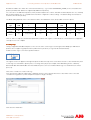
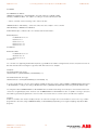
Motion Control Products
Application note
Connecting CP600 to motion products via Modbus RTU
AN00200-003
Seamless high speed serial communication
between HMI and motion products
Introduction
The CP600 range of intelligent HMI panels is able to
communicate with other peripherals (e.g. AC500 PLCs, ABB motion products) via a selection of communication protocols. This
application note details how these HMIs can interface with ABB motion products via Modbus RTU. For general guidance on the use
of Panel Builder 600 please refer to ABB manual 2CDC159007M0201.
To configure a CP600 HMI to communicate with an ABB motion control product via Modbus RTU requires Panel Builder 600
version 1.80.00.34 (or later). Please contact your local Sales office if you need to update your existing version of this software.
Integrated Modbus RTU support is available on the following ABB motion control products:
NextMove ES / ESB-2
NextMove e100
MicroFlex e100
MotiFlex e100
MicroFlex e150
Refer to application note AN00198 for further details on the operation of Modbus RTU on these products.
Modbus RTU uses a serial-based physical medium (either RS232, 2 wire RS485 or 4 wire RS422 depending on product).
Refer also to application note AN00199 for details on connecting CP600 HMIs to ABB motion control products via Modbus TCP.
ABB Motion control products
www.abb.com/motion
1
Application note
Connecting CP600 to motion products via Modbus RTU
AN00200-003
Motion Product Configuration
Integrated Modbus RTU operation is included with the following firmware versions:
e100 products - firmware version 5633 (or later)
e150 products - firmware version 5707 (or later)
NextMove ES / ESB2 - firmware version 5424 or later (compiler Target Format 13) or firmware version 5454 or later (compiler
Target Format 14)
NextMove ES/ESBES/ESB-2 and e100 Product Configuration
As Modbus RTU is a serial-based protocol it is vital to ensure the motion product’s serial node address is set using either
BUSNODE(_busSERIAL1) in a Mint program or via the “Connectivity” screen within Mint Workbench, Address 0 should be avoided
as this is reserved for broadcast functions.
It is also necessary to set the required baud rate either using SERIALBAUD(_TERM1) in a Mint program or via the “Connectivity”
screen within Mint Workbench, The motion products do not support operation of Modbus RTU at 9600 baud and there are limited
selections of baud rate for the CP600 HMIs. Therefore the selection of baud rate is restricted to one of the following:
19200
38400
57600
All Modbus parameters are configured via the MODBUSPARAMETER Mint keyword.
Before enabling Modbus operation it is necessary to set the correct byte and word order to suit the connected Modbus client
(master), in this case the CP600 HMI, and to configure how Modbus registers in the received data packets are mapped to internal
data areas in the Mint controller (see also application note AN00198).
As ABB PLC products use big endian byte order and big endian word order the Mint program needs to ensure the relevant Modbus
parameters are set accordingly (via the MODBUSPARAMETER keyword, typically as part of the Mint startup module) to ensure
connectivity between the CP600 HMI and any other networked ABB Modbus RTU devices (e.g. an AC500 PLC):
Example Mint code – Mint Modbus RTU slave connected to CP600 using Comms array
BUSNODE (_busSERIAL1) = 3
‘Mint controller is node 3
SERIALBAUD (_TERM1) = 57600
‘Using 57600 baud
MODBUSPARAMETER (_busSERIAL1, _mpBYTE_ORDER) = 0 ‘Use big endian byte order
MODBUSPARAMETER (_busSERIAL1, _mpWORD_ORDER) = 0 ‘Use big endian word order
MODBUSPARAMETER (_busSERIAL1, _mpREGISTER_MAPPING) = _rmCOMMS_ARRAY
MODBUSPARAMETER (_busSERIAL1, _mpENABLE) = 1
NextMove ES / ESB-2 only supports mapping of the Comms array to Modbus registers. When using e100 products, as an
alternative to the Comms array, it is also possible to map Net Data locations to Modbus registers by setting the
_mpREGISTER_MAPPING parameter to _rmNET_DATA.
Most new applications using e100 products are likely to utilise NetData as there are 1000 of these (as opposed to 99 Comms
locations) and 32 NetData events (as opposed to only 10 Comms events).
Applications using NextMove ES / ESB-2 are restricted to 5 Comms events (1 to 5). The operation of Mint events is detailed later in
this document.
ABB Motion control products
www.abb.com/motion
2
Application note
Connecting CP600 to motion products via Modbus RTU
AN00200-003
e150 Product Configuration
All Modbus parameters are configured via the ‘Configuration’ menu within Workbench once online to the product (and the resulting
settings are stored on the product as part of its Mint Device Configuration (MDC) file).
Before enabling Modbus operation it is necessary to set the correct byte and word order to suit the connected Modbus client
(master), in this case the CP600 HMI.
As ABB PLC products use big endian byte order and big endian word order the ‘Configure Communication Interfaces’ page of the
Configuration wizard provides settings (as shown above) to allow the e150 product to operate this way.
e150 products inherently map Modbus registers onto Net Data (so there is no requirement to use the MODBUSPARAMETER
keyword to initialise this mapping). It is not possible to target the e150’s Comms array via Modbus.
To enable Modbus on e150 select the ‘Serial’ section of the ‘Configure Communication Interfaces’ dialog and select Modbus RTU
as the protocol…
The other settings on this dialog should be made to suit the connection to the HMI (this is detailed later when discussing the
protocol setup in the HMI project).
ABB Motion control products
www.abb.com/motion
3
Application note
Connecting CP600 to motion products via Modbus RTU
AN00200-003
Register Mappings
All CP600 Modbus functions target a common data area in the Mint controller (as set by the Mint keyword ModbusParameter
(_mpREGISTER_MAPPING) if using a motion product other than e150 or fixed as Net data when using an e150 product). These
data areas have a fixed mapping with respect to the Modbus registers used by the HMI as shown by the table below (equivalent
AC500 addresses are also shown for reference):
Server Modbus
AC500 address
register
0
%MW0.0
1
%MW0.1
2
%MW0.2
3
%MW0.3
4
%MW0.4
5
%MW0.5
…
---
198
%MW0.198
199
%MW0.199
200
%MW0.200
201
%MW0.201
202
%MW0.202
203
%MW0.203
…
---
1996
%MW0.1996
1997
%MW0.1997
1998
%MW0.1998
1999
%MW0.1999
%MD0.0
%MD0.1
%MD0.2
--%MD0.99
%MD0.100
%MD0.101
--%MD0.998
%MD0.999
Mint Comms array
Mint Netdata array
(Comms=Real, Commsinteger = DWord)
(Netfloat = Real, Netinteger = DWord)
Invalid
Invalid
Element 1 MSW
Element 1 LSW
Element 2 MSW
Element 2 LSW
---
Invalid
Element 1
Element 2
---
Element 99 MSW
Element 99 LSW
Invalid
Invalid
Invalid
Invalid
---
Element 99
Invalid
Invalid
---
Invalid
Invalid
Invalid
Invalid
Invalid
Invalid
Element 0 MSW
Element 0 LSW
Element 1 MSW
Element 1 LSW
Element 2 MSW
Element 2 LSW
--Element 99 MSW
Element 99 LSW
Element 100 MSW
Element 100 LSW
Element 101 MSW
Element 101 LSW
--Element 998 MSW
Element 998 LSW
Element 999 MSW
Element 999 LSW
Element 0
Element 1
Element 2
--Element 99
Element 100
Element 101
--Element 998
Element 999
LSW – Least Significant Word : MSW – Most Significant Word
HMI Protocol Configuration
Having started Panel Builder 600 and launched a new project you will be presented with a blank screen representing the first page
of your HMI application. At the left of the screen is the “ProjectView” which shows a tree structure of the available functions within
the HMI project.
Expand the “Config” folder if necessary and then double-click the “Protocols” icon…
Now click on the “+” button to add a protocol to the HMI project…
ABB Motion control products
www.abb.com/motion
4
Application note
Connecting CP600 to motion products via Modbus RTU
AN00200-003
A dropdown control appears under the PLC heading, click on this to display the list of available protocols…
We need to select the ABB Modbus RTU protocol. This is a client (master) protocol that allows the CP600 HMI to communicate
with both ABB PLCs and motion control products. The ABB versions of Modbus protocols differ from the generic Modbus
protocols available in two ways:
1.
2.
The ABB Modbus protocols use big endian word order for data encoded into the Modbus data packets
The ABB Modbus protocols allow PLC specific addresses to be utilised in preference to generic Modbus registers
Note that there are no ABB specific versions of the Modbus Server protocols (so the CP600 HMI would usually be used as a master
device when connecting to ABB products).
Having selected ABB Modbus RTU the software will now ask us to configure the connected devices…
If the HMI is connected to a single Modbus RTU slave device (e.g. e100 controller or AC500 PLC) there is no need to select the
‘PLC Network’ check box. If there are multiple slave devices connected to the HMI then it is essential this box is selected (for the
purposes of this application note we will select this option).
ABB Motion control products
www.abb.com/motion
5
Application note
Connecting CP600 to motion products via Modbus RTU
AN00200-003
The dialog changes slightly and now includes an additional area showing the slave devices that have been added to the Modbus
RTU network.
Click on the ‘Add’ button…the software now asks the user to enter details about the connected slave device….
Our ABB Motion Product (e100 controller) we’re using for this example has a serial node address of 1 (where this was set either by
BUSNODE(_busSERIAL1) or via Mint Workbench) so we’ve entered this as the Node ID.
The Timeout (in ms) is how long the HMI will wait for a reply from the connected slave(s) before deciding a particular communication
transaction has failed. Typically the responses should occur within 10ms so the default timeout of 1 second (1000ms) is adequate.
The delay setting determines how long the HMI waits before processing further Modbus transactions. If this is set to 0 the HMI will
read/write data as quickly as possible (e.g. after reading data from the slave it will read again with no delay). In practise there’s no
point updating the HMI this quickly (and the more frequently we communicate with the controller the greater the loading on the
connected slave processors) so a setting of 200 to 400ms is more typical.
Num of repeats sets how many times the HMI attempts a particular Modbus transaction before deciding a communication error has
occurred. The default value of 2 is adequate for all applications.
Finally we need to select a PLC model. When using Modbus RTU we are able to select from NextMove ES/ESB-2, e100 motion
product or e150 motion product. For this example we’ll select an e100 motion product.
The software returns to the previous screen and now shows our configured node in the list of slave controllers. To add another
slave device repeat the above process. To modify any settings, highlight the slave controller and click on the “Modify” button.
Once all the required slave devices have been added click on the “Comm…” button. We can now setup the properties of the HMI’s
serial port to suit the connected slave devices…
For HMIs with a single 9 way d-type connector select “Com1” as the required port. If the HMI has more than one serial port set
‘Port’ to match whichever port is physically wired.
ABB Motion control products
www.abb.com/motion
6
Application note
Connecting CP600 to motion products via Modbus RTU
AN00200-003
Baudrate should be set to match the connected slave device(s) – e.g. to match SERIALBAUD(_TERM1) of the connected motion
product (remember that 9600 is not supported by ABB motion products).
For connection to an ABB motion products, Parity should usually be set to “None”, Data Bits should usually be set to “8”, and Stop
bits should usually be set to “1” (only MicroFlex e150 allows configuration of these settings – the default settings are None/8/1 to
match the other motion products).
The Mode setting depends on the connected slave device. The table below shows the possible connection options:
Connection
NextMove
Type
e100
2
RS232
Yes
Yes (by variant)
2 wire
RS485
4 wire
RS422
NextMove ES/ESB-
MicroFlex e100
MotiFlex e100
No
No
MicroFlex
AC500
AC500 Eco
Yes
No
Yes
Yes
No
No
e150
No
No
Yes
Yes
Yes
Yes (by variant)
No
No
No
Yes
Yes
Click on “OK” to accept the communication parameters and then “OK” again to confirm the list of connected slaves. Configuration
of the protocol is now complete.
Creating Tags
Having configured the Modbus RTU protocol we can now start to create Tags to use throughout the HMI project. ABB motion
products do not support Tag Export functions (unlike the PLC products) so Tags must be entered manually.
Double-click the “Tags” icon in the ProjectView window…
The Tag list screen now appears in the right hand pane. A filter at the top of this screen allows the user to select whether they wish
to view Tags associated with a specific protocol or all Tags in the project (for example, if the HMI is being used as a Gateway
between Modbus RTU and Modbus TCP there will be two protocols in use and there will be Tags associated with each of these
protocols).
Click on the “+” button to create a new Tag…
If we selected “PLC Network” earlier when configuring our protocol the software will ask us to select which of the connected
controllers the Tag relates to (in this example we only have a single controller)…
Now select the “Field” tab….
ABB Motion control products
www.abb.com/motion
7
Application note
Connecting CP600 to motion products via Modbus RTU
AN00200-003
The field tab lets us program which memory location in the motion controller the Tag relates to. The available ‘Memory Type’
selections are specific to the PLC model selected as shown by the table below:
PLC Type
Comms Array
Net Data
NextMove ES/ESB-2
Yes
No
E100 motion product
Yes
Yes
E150 motion product
No
Yes
You should ensure that all tags used in the HMI project are setup to use a single Memory Type (i.e. do not attempt to mix memory
types in the same project).
There is a third Memory type available (NO_IP)….this is not currently used.
The other entries on this dialog are as follows:
Offset- - this relates to the index into the Comms Array or Net Data area - e.g. 3 to access Comms(3)
Subindex – this entry varies depending on the data type. For Boolean (bit) level data the subindex can be 0 to 31 (corresponding to
the 32 bits in a commsinteger or netinteger location). For Byte level data the subindex can be 0 to 3 (where 0 is the least significant
byte). For Word level data the subindex can be 0 or 1 (where 0 is the least significant word).
Data type – select from Boolean, Byte (signed 8 bit integer), Short (signed 16 bit integer), Int (signed 32 bit integer), unsignedByte,
unsignedShort, unsignedInt, Float (32 bit IEEE) or String
Arraysize – only used if String data type selected. Specifies the number of characters/bytes to be used by the string. A
commsinteger/netinteger location can store up to 4 characters so if an array size of more than 4 is specified then subsequent data
locations are used to store the additional characters - e.g. If a tag was configured to use Comms Array Offset 1 as a String and
“ABCDEF” was to be stored this would result in 0x41424344 (“ABCD”) being stored in Commsinteger(1) and 0x45460000 (“EF”)
being stored in Commsinteger(2).
Conversion – this entry allows the user to add a translation to (e.g. word swap) the data
Index – this setting is not used.
So as an example, if we needed a Tag to use in conjunction with a lamp in the HMI project (i.e. a Boolean/bit value) and we wanted
this to relate to Bit 19 of NetData 2 in our ABB e100 motion product (e.g. NextMove e100) we would setup our Tag as shown
below:
ABB Motion control products
www.abb.com/motion
8
Application note
Connecting CP600 to motion products via Modbus RTU
AN00200-003
If we now click OK the software allows us to enter a name for our newly created Tag…
We can now click on the “+” button again to continue to add Tags to the project.
Using Modbus Data in Mint Programs on ABB Motion Products
The table below shows how various data types are likely to be used by a Mint program:
Data Type
Comms Array
NetData Array
Boolean
CommsInteger
NetInteger
Byte (signed or unsigned)
CommsInteger
NetInteger
Short (signed or unsigned)
CommsInteger
NetInteger
Int (signed or unsigned)
CommsInteger
NetInteger
String
CommsInteger
NetInteger
Float
Comms
NetFloat
The simplest way to access data with widths less than 32 bits (i.e. bits, bytes and words) in a Mint program is via the Mint BITFIELD
keyword (only supported by firmware using compiler Target Format 14 or greater – i.e. NextMove ES / ESB-2 running 5454 or later
or e100/e150 products).
If we use our previous example where we configured an HMI tag related to Bit 19 of NetData location 2, our Mint program could
contain the following code to read this bit from the HMI…
Bitfield BitData
DoubleWord As 0 to 31
Bit0 As 0
Bit1 As 1
Bit2 As 2
Bit3 As 3
Etc…
Bit19 As 19
Bit20 As 20
Etc…
ABB Motion control products
www.abb.com/motion
9
Application note
Connecting CP600 to motion products via Modbus RTU
AN00200-003
End Bitfield
Dim HMIBitData As BitData
HMIBitData.DoubleWord = NETINTEGER(2) ‘Read all 32 bits into a bitfield variable
OUTX(0) = HMIBitData.Bit19 ‘Set output 0 according to the value written by the HMI
…and we could then use the following code to write to this bit…
HMIBitData.Bit19 = INSTATEX(1) ‘set bit 19 to reflect the state of input 1 on the controller
NETINTEGER(2) = HMIBitData.DoubleWord
Similar BitField types could be used to encode Byte and Word level data…
BitField ByteData
DoubleWord As 0 to 31
Byte0 As 0 to 7
Byte1 As 8 to 15
Byte2 As 16 to 23
Byte3 As 24 to 31
End BitField
BitField WordData
DoubleWord As 0 to 31
Word0 As 0 to 15
Word1 As 16 to 31
End BitField
For controllers not supporting the BITFIELD keyword (e.g. NextMove ES / ESB-2 running firmware version 5424) data less than 32
bits wide must be extracted using the logical OR, AND, NOT functions for example.
Examples:
Dim nNetData2Bit19 As Integer
nNetData2Bit19 = ((NETINTEGER(2) & 0x00080000) > 0)
Dim nNetData2Word1 As Integer
nNetData2Word1 = SHIFT((NETINTEGER(2) & 0xFFFF0000), 16)
Accessing 32 bit data (int or Float) is much simpler, the Mint program just needs to utilise COMMS, COMMSINTEGER, NETFLOAT
or NETINTEGER according to the setting of Modbus parameter _mpREGISTER_MAPPING and the programmed HMI data type.
For string data either COMMSINTEGER or NETINTEGER data should be used. Strings are made up of character data where each
character is an eight bit (byte) value. Therefore each COMMSINTEGER or NETINTEGER location is capable of storing 4 characters.
If the HMI Tag has been programmed to store more than 4 characters then successive locations are utilised as required.
Example:
A label on our HMI screen needs to display text up to 10 characters in length. The screenshot below shows how a Tag could be
programmed to allow this (using COMMSINTEGER(1) or NETINTEGER(1) depending on the register mapping setup by the Mint
program)…
ABB Motion control products
www.abb.com/motion
10
Application note
Connecting CP600 to motion products via Modbus RTU
AN00200-003
The ‘ArraySize’ field in the dialog determines the number of characters the string Tag can store. In this case 10 characters means
the HMI will access COMMSINTEGER(1), COMMSINTEGER(2) and the top 16 bits of COMMSINTEGER(3).
The table below illustrates some example strings (use of COMMSINTEGER has been assumed for this example):
CommsInteger (1)
CommsInteger (2)
CommsInteger (3)
0x41424344 (hex)
0
0
HMI String Display
“ABCD”
0x41424344 (hex)
0x45460000 (hex)
0
“ABCDEF”
0x41424344 (hex)
0x45464748 (hex)
0
“ABCDEFGH”
0x41424344 (hex)
0x45464748 (hex)
0x494A0000 (hex)
“ABCDEFGHIJ”
“ABCDEFGHIJ”
0x41424344 (hex)
0x45464748 (hex)
0x494A7691 (hex)
0
0x45464748 (hex)
0x494A0000 (hex)
“”
0x41424344 (hex)
0
0x494A0000 (hex)
“ABCD”
0x41420044 (hex)
0x45464748 (hex)
0x494A0000 (hex)
“AB”
You can see from the above table that the bottom 16 bits of CommsInteger(3) are not used. Also, as soon as a NULL (ASCII value
0) is encountered in the data the string is terminated, regardless of the contents of the remainder of the CommsInteger locations.
Mint Events
It is possible to associate Mint events / interrupts with Comms or NetData locations.
NextMove ES/ESB-2 only support the Comms array and will generate Mint Comms Events (1 to 5) whenever the HMI (or other
Modbus client) writes to one of the first five Comms locations. When using ES / ESB-2 the data does not have to change, whenever
a Comms location is written to the event is raised.
If using e100 products it is possible to utilise Comms events and / or Netdata events. Comms events (1 to 10) and NetData events
(0 to 31) are raised whenever the data in the associated location is changed. Writing the same value to one of these locations will
not raise an event in Mint.
If using e150 products it is only possible to utilise Netdata events. NetData events (0 to 31) are raised whenever the data in the
associated location is changed. Writing the same value to one of these locations will not raise an event in Mint.
ABB Motion control products
www.abb.com/motion
11
Application note
Connecting CP600 to motion products via Modbus RTU
AN00200-003
Physical Connection
The table below shows the physical connection possibilities for Mint products supporting integrated Modbus protocols. AC500 and
CP600 products are included for reference.
Connection Type
NextMove e100
NextMove
MicroFlex e100
MotiFlex e100
AC500
AC500 Eco
CP600
Yes (by variant)
No
No
Yes
No
Yes
ES/ESB-2
RS232
Yes
2 wire RS485
No
No
Yes
Yes
Yes
Yes
Yes
4 wire RS422
Yes
Yes (by variant)
No
No
No
No
Yes
Ethernet
Yes
No
Yes
Yes
Yes
Yes (by variant)
Yes
When using Modbus RTU consideration must be given to the above table if there are multiple slave devices. For example, if the
system comprises a CP600 HMI as the Modbus master and a NextMove ESB-2 and AC500 Eco PLC as slave devices then it is not
possible to connect all of these together on the same serial network as they share no common connection types. A system like this
would require the HMI to operate using two protocols (e.g. Modbus TCP to the Eco PLC using the Ethernet PLC variant and
Modbus RTU to the NextMove ESB-2 using either RS232 or RS422).
The following tables show the pinouts of the various products for each connection type:
Connection
NextMove e100 /
Type
ES / ESB -2
MicroFlex e150
MicroFlex e100 /
1 : Shield
2 : RXD
2 : TXD
2 : Not Used
3 : TXD
3 : Not Used
3 : TXD
5 : GND
4 : RTS
Not Available
Not Available
5 : GND
4 : RXD
Not Available
5 : Not Used
6 : +5v (see note 2)
6 : +5v (see note 3)
7 : CTS
7 : RTS
7 : RXD
8 : CTS
8 : Not Used
8 : RTS
9 : DGND
9 : CTS
9 : Not Used
1 : Not Used
1 : TXA/+
1 : GND
2 : RXB/- (see note 4)
2 : TXB/-
2 : Not Used
3 : TXB/-
3 : GND
3 : TX-
4 : Not Used
5 : GND
6 : Not Used
4 : 7v out (see
4 : RX- (see note 4)
note 1)
5 : RXA/+ (see
note 4)
Not Available
Not Available
Not Available
6 : RXB/- (see
7 : RX+ (see note 4)
8 : RXA/+ (see note
8 : TX+
4)
9 : Not Used
9 : Not Used
1 : A+ (see note
1 : A+ (see note 5)
1 : Shield
1 : Shield
1 : GND
2 : B- (see note 5)
2 : Not Used
2 : Not Used
2 : Not Used
3 : GND
3 : GND
3 : + (see note 5)
3 : + (see note 5)
3 : - (see notes 5,6)
4 : 7v out (see
4 : 7v out (see note
note 1)
1)
4 : Not Used
4 : Not Used
4 : - (see notes 5,6)
5 : not used
5: Not Used
5 : GND
5 : GND
5 : Not Used
6 : not used
6 : Not Used
6 : +5v (see note 2)
6 : +5v (see note 2)
6 : +5v
7 :Not Used
7 :Not Used
7 : + (see notes 5,6)
8 : - (see note 5)
8 : - (see note 5)
8 : + (see notes 5,6)
9 : Not Used
9 : Not Used
9 : Not Used
5)
2 : B- (see note
5)
Not Available
ABB Motion control products
www.abb.com/motion
5 : Not Used
6 : +5v
note 4)
7 : TXA/+
RS485
CP600
1 : GND
6 : Not Used
RS422
AC500 Eco
1 : Shield
4 : Not Used
RS232
AC500
MotiFlex e100
12
Application note
Notes:
1.
2.
3.
4.
5.
6.
Connecting CP600 to motion products via Modbus RTU
AN00200-003
The 7v output on MicroFlex / MotiFlex e100 and e150 products should not be connected. Ensure pin 4 at the e100 RJ12
connector is isolated from any external connection
Do not connect 5v output on PLCs to any external connection
Do not connect 5v output on CP600 to any external connection
When using RS422 ensure a 120 ohm terminating resistor is fitted across RX+ and RX- at each end of the serial network
(this may be via a terminator switch if one is provided on the product)
When using RS485 ensure a 120 ohm terminating resistor is fitted across + and – at each end of the serial network (this
may be via a terminator switch if one is provided on the product)
To use the CP600 HMI in 2 wire RS485 mode you must link the two – pins (3 and 4) together and the two + pins (7 and 8)
together
Example connections:
CP600 to NextMove e100/ESB-2 via RS232
1
3
4
CP600
7
8
5
2
3
7
8
CP600 to NextMove e100/ES/ESB-2 via RS422
1
8
CP600
3
7
120R
4
5
8
2
7
3
CP600 to MicroFlex e100 / MotiFlex e100 / MicroFlex e150 via RS485
1
3
7
1
CP600
8
120R
3
2
4
CP600 to MicroFlex e150 via RS422
1
8
CP600
3
7
120R
4
3
4
5
1
2
NextMove
120R
120R
120R
NextMove
e100/e150 drive (Dip switch 2
ON to connect 120R resistor
when using e150)
e150 (Dip switch 1 ON
to connect 120R
resistor)
Contact us
For more information please contact your
local ABB representative or one of the following:
© Copyright 2012 ABB. All rights reserved.
Specifications subject to change without notice.
www.abb.com/motion
www.abb.com/drives
www.abb.com/drivespartners
www.abb.com/PLC
ABB Motion control products
www.abb.com/motion
13


![*Sted Plus UG Jan 2012 [2].indd](http://vs1.manualzilla.com/store/data/005710511_1-f757ed41a0935df19f469c7cee361c5b-150x150.png)