1
xx
ZZZ
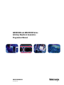
AWG5000B and AWG7000B Series
Arbitrary Waveform Generators
Programmer Manual
*P077006100*
077-0061-00
xx
ZZZ
AWG5000B and AWG7000B Series
Arbitrary Waveform Generators
Programmer Manual
www.tektronix.com
077-0061-00
Copyright © Tektronix, Inc. All rights reserved.
Tektronix products are covered by U.S. and foreign patents, issued and pending. Information in this publication
supersedes that in all previously published material. Specifications and price change privileges reserved.
Tektronix, Inc., P.O. Box 500, Beaverton, OR 97077
TEKTRONIX and TEK are registered trademarks of Tektronix, Inc.
AWG5000 and AWG7000 Series Programmer Online Help, part number 076-0146-00.
Contacting Tektronix
Tektronix, Inc.
14200 SW Karl Braun Drive
P.O. Box 500
Beaverton, OR 97077
USA
For product information, sales, service, and technical support:
In North America, call 1-800-833-9200.
Worldwide, visit www.tektronix.com to find contacts in your area.
Warranty 2
Tektronix warrants that this product will be free from defects in materials and workmanship for a period of
one (1) year from the date of shipment. If any such product proves defective during this warranty period,
Tektronix, at its option, either will repair the defective product without charge for parts and labor, or will
provide a replacement in exchange for the defective product. Parts, modules and replacement products used
by Tektronix for warranty work may be new or reconditioned to like new performance. All replaced parts,
modules and products become the property of Tektronix.
In order to obtain service under this warranty, Customer must notify Tektronix of the defect before the
expiration of the warranty period and make suitable arrangements for the performance of service. Customer
shall be responsible for packaging and shipping the defective product to the service center designated by
Tektronix, with shipping charges prepaid. Tektronix shall pay for the return of the product to Customer if
the shipment is to a location within the country in which the Tektronix service center is located. Customer
shall be responsible for paying all shipping charges, duties, taxes, and any other charges for products returned
to any other locations.
This warranty shall not apply to any defect, failure or damage caused by improper use or improper or
inadequate maintenance and care. Tektronix shall not be obligated to furnish service under this warranty a) to
repair damage resulting from attempts by personnel other than Tektronix representatives to install, repair or
service the product; b) to repair damage resulting from improper use or connection to incompatible equipment;
c) to repair any damage or malfunction caused by the use of non-Tektronix supplies; or d) to service a product
that has been modified or integrated with other products when the effect of such modification or integration
increases the time or difficulty of servicing the product.
THIS WARRANTY IS GIVEN BY TEKTRONIX WITH RESPECT TO THE PRODUCT IN LIEU OF ANY
OTHER WARRANTIES, EXPRESS OR IMPLIED. TEKTRONIX AND ITS VENDORS DISCLAIM ANY
IMPLIED WARRANTIES OF MERCHANTABILITY OR FITNESS FOR A PARTICULAR PURPOSE.
TEKTRONIX’ RESPONSIBILITY TO REPAIR OR REPLACE DEFECTIVE PRODUCTS IS THE SOLE
AND EXCLUSIVE REMEDY PROVIDED TO THE CUSTOMER FOR BREACH OF THIS WARRANTY.
TEKTRONIX AND ITS VENDORS WILL NOT BE LIABLE FOR ANY INDIRECT, SPECIAL,
INCIDENTAL, OR CONSEQUENTIAL DAMAGES IRRESPECTIVE OF WHETHER TEKTRONIX OR
THE VENDOR HAS ADVANCE NOTICE OF THE POSSIBILITY OF SUCH DAMAGES.
Table of Contents
Getting Started
Introduction ....................................................................................................... 1-1
Remote Control ................................................................................................... 1-2
GPIB Parameters ................................................................................................. 1-3
LAN Parameters .................................................................................................. 1-4
Connecting to the Instrument using GPIB ..................................................................... 1-5
Setting Up GPIB Communication .............................................................................. 1-6
Documentation.................................................................................................... 1-9
Sample Program ................................................................................................ 1-10
Syntax and Commands
Command Syntax.................................................................................................
Syntax Overview.............................................................................................
Command and Query Structure ............................................................................
Clearing the Instrument .....................................................................................
Command Entry..............................................................................................
Parameter Types .............................................................................................
SCPI Commands and Queries ..............................................................................
Command Groups ..............................................................................................
Control group commands .................................................................................
Calibration Group Commands............................................................................
Diagnostic Group Commands ............................................................................
Display Group Commands................................................................................
Event Group Commands ..................................................................................
Instrument Group Commands ............................................................................
Mass Memory Group Commands........................................................................
Output Group Commands.................................................................................
Sequence Group Commands .............................................................................
Source Group Commands.................................................................................
Status Group Command...................................................................................
Synchronization Group Commands .....................................................................
System Group Commands ................................................................................
Trigger Group Commands ................................................................................
Waveform Group Commands ............................................................................
AWG5000B and AWG7000B Series Programmer Manual
2-1
2-1
2-1
2-3
2-3
2-5
2-9
2-11
2-11
2-12
2-12
2-13
2-13
2-13
2-13
2-14
2-14
2-16
2-18
2-19
2-19
2-20
2-20
i
Table of Contents
Command Descriptions ........................................................................................
2-23
Status and Events
Status and Event Reporting......................................................................................
Status Reporting Structure ..................................................................................
Registers ......................................................................................................
Status Registers ..............................................................................................
Status Byte Register (SBR) .................................................................................
Standard Event Status Register (SESR) ...................................................................
Operation Enable Register (OENR) .......................................................................
Operation Condition Register (OCR)......................................................................
Operation Event Register (OEVR).........................................................................
Questionable Condition Register (QCR) ..................................................................
Enable Registers .............................................................................................
Event Status Enable Register (ESER) .....................................................................
Service Request Enable Register (SRER).................................................................
Questionable Enable Register (QENR)....................................................................
Queues ........................................................................................................
Operation Status Block......................................................................................
Questionable Status Block ..................................................................................
Standard/Event Status Block ...............................................................................
Synchronizing Execution .................................................................................
Messages and Codes ...........................................................................................
Messages and Codes.......................................................................................
Command Errors...........................................................................................
Execution errors............................................................................................
Device-specific Errors.....................................................................................
Query Errors................................................................................................
Power On Event............................................................................................
User request Event.........................................................................................
Request Control Event ....................................................................................
Operation Complete Event................................................................................
3-1
3-1
3-2
3-3
3-3
3-4
3-5
3-5
3-5
3-5
3-5
3-6
3-6
3-7
3-7
3-8
3-8
3-9
3-10
3-11
3-11
3-12
3-13
3-15
3-15
3-16
3-16
3-16
3-16
Appendices
Appendix A: Character Charts .................................................................................
Appendix B: GPIB Interface Specifications ..................................................................
GPIB Interface Specifications .............................................................................
Interface Functions .........................................................................................
Interface Messages .........................................................................................
ii
A-1
B-1
B-1
B-1
B-3
AWG5000B and AWG7000B Series Programmer Manual
Table of Contents
Appendix C: SCPI Conformance Information ...............................................................
Appendix D: Raw Socket Specification.......................................................................
Appendix E: Factory Initialization Settings ..................................................................
Appendix F: Compatibility with Other Instruments .........................................................
AWG5000B and AWG7000B Series Programmer Manual
C-1
D-1
E-1
F-1
iii
Table of Contents
iv
AWG5000B and AWG7000B Series Programmer Manual
Getting Started
Introduction
This online programmer guide provides you with the information you need to
use commands for remotely controlling your instrument. With this information,
you can write computer programs that will perform functions such as setting the
front-panel controls, selecting clock source, setting sampling rate, and exporting
data for use in other programs. In addition to the traditional GPIB electronic
interface, (referred to as the physical GPIB interface), your instrument is provided
with a TekVISA GPIB-compatible interface, (referred to as the virtual GPIB
interface).
Refer to Documentation for information on related manuals and documents.
The programmer guide is divided into the following major topics (books):
Getting Started: This topic introduces you to the online help and provides
basic information about setting up your instrument for remote control.
Command Syntax: This topic provides an overview of the command syntax
that you will use to communicate with the instrument and other general
information about commands, such as how commands and queries are
constructed, how to enter commands, constructed mnemonics, and argument
types.
Command Groups: This topic contains all the commands listed in functional
groups. Each group consists of an overview of the commands in that group and
a table that lists all the commands and queries for that group. You can click a
command in the listing to display a detailed description of the command.
Status and Events: This topic discusses the status and event reporting system
for the GPIB interface. This system informs you of certain significant events
that occur within the instrument. Topics that are discussed include registers,
queues, event handling sequences, synchronization methods, and messages
that the instrument may return, including error messages.
Miscellaneous: This topic contains miscellaneous information, such as a
table of the factory initialization (default) settings, and GPIB interface
specifications that may be helpful when using remote commands to control
the instrument.
AWG5000B and AWG7000B Series Programmer Manual
1-1
Remote Control
Remote Control
The AWG5000 and AWG7000 Series support GPIB interface and LAN
interface. To set the GPIB address, you can use the System Menu > GPIB/LAN
Configuration menu.
GPIB Interface
LAN Interface
1-2
The GPIB enables up to 15 devices (including the controller) to be connected for
concurrent use. With the arbitrary waveform generator connected to an external
computer via GPIB, you can use the computer to remotely control your AWG5000
and AWG7000 Series. With the AWG5000 and AWG7000 Series, you can use
the GPIB interface as a controller. See the GPIB Parameters for information
on GPIB parameters.
The AWG5000 and AWG7000 Series accept two types of Ethernet LAN
connections; one is simple (“Raw Socket”) connection, and the other is VXI-11
protocol. See the LAN Parameters for information on LAN parameters.
AWG5000B and AWG7000B Series Programmer Manual
GPIB Parameters
GPIB Parameters
To use the GPIB, the AWG5000 and AWG7000 Series require you to configure
the GPIB mode and the GPIB address.
Talk/Listen: Select this mode to remotely control your AWG5000 and
AWG7000 Series using an external computer as the controller.
Off Bus: Select this mode to electronically disconnect the AWG5000 and
AWG7000 Series from the GPIB bus.
Address: This address is a number that allows the software to identify each
device connected to the GPIB bus. You must specify a unique number from 0
to 30 for each device.
AWG5000B and AWG7000B Series Programmer Manual
1-3
LAN Parameters
LAN Parameters
In the AWG5000 and AWG7000 Series, set parameters to start or stop a process
that communicates through LAN. The instrument can communicate with LAN
using the following methods:
VXI-11 Server (LAN): VXI-11 protocol used through TekVISA. To use this
protocol, TekVISA must also be installed on the remote controller (PC).
Raw Socket (LAN): TCP/IP protocol is used. Use the GPIB/LAN
Configuration option to set the socket communication On and Off. You can
specify the port number for the Raw Socket interface. This port number must
be assigned to the application software or the Ethernet driver on the external
controller.
By default, the AWG5000 and AWG7000 Series are specified to automatically
acquire an IP address by DHCP. Refer to Windows documentation regarding
network-related parameters. For TekVISA, refer to the TekVISA manual.
1-4
AWG5000B and AWG7000B Series Programmer Manual
Connecting to the Instrument using GPIB
Connecting to the Instrument using GPIB
Your instrument has a 24-pin GPIB connector on its rear panel. This connector
has a D-type shell and conforms to IEEE Std 488.1–1987. Attach an IEEE Std
488.1–1987 GPIB cable to this connector and to your controller as shown in the
following figure.
AWG5000B and AWG7000B Series Programmer Manual
1-5
Setting Up GPIB Communication
Setting Up GPIB Communication
Before setting up your instrument for remote communications using the electronic
(physical) GPIB interface, you should familiarize yourself with the following
GPIB requirements:
A unique device address must be assigned to each device on the bus. No two
devices can share the same device address.
No more than 15 devices can be connected to any one line.
One device should be connected for every 6 feet (2 meters) of cable used. No
more than 65 feet (20 meters) of cable should be used to connect devices
to a bus.
At least two-thirds of the devices on the network should be powered on while
using the network.
Connect the devices on the network in a star or linear configuration. Do not
use loop or parallel configurations.
Setting the GPIB Address
To function correctly, your instrument must have a unique device address. The
default settings for the GPIB configuration are:
GPIB Address: 1
GPIB Mode: Talk/Listen
To change the GPIB address settings, do the following:
1. Select GPIB/LAN Configuration… from the System menu.
1-6
AWG5000B and AWG7000B Series Programmer Manual
Setting Up GPIB Communication
2. The GPIB/LAN Configuration dialog box is displayed.
AWG5000B and AWG7000B Series Programmer Manual
1-7
Setting Up GPIB Communication
3. Change the GPIB Address to a unique address.
4. Click OK button.
1-8
AWG5000B and AWG7000B Series Programmer Manual
Documentation
Documentation
In addition to this AWG5000 and AWG7000 Series Programmer Online Guide,
the following documentation is included with this instrument:
AWG5000 or AWG7000 Series Arbitrary Waveform Generators Quick Start
User Manual. The Quick Start User Manual has information about installing
and operating your instrument.
AWG5000 and AWG7000 Series Arbitrary Waveform Generators User Online
Help. The User Online Help system is integrated with the User Interface
application that ships with this product. The online help provides in-depth
operation and user interface help.
AWG5000 or AWG7000 Series Arbitrary Waveform Generators Specifications
and Performance Verification Technical Reference Manual. The technical
reference manual is a PDF only manual; it includes both the specifications
and the performance verification procedure.
AWG5000 and AWG7000 Series Service Manual is a PDF only manual; it
includes procedures to service the instrument to the module level. The service
manual is available on the Tektronix Web site (www.tektronix.com/manuals).
AWG5000B and AWG7000B Series Programmer Manual
1-9
Sample Program
Sample Program
The sample program illustrates methods you can use to control the arbitrary
waveform generator. This program sends waveform data and then starts waveform
generation. You can access the sample program from Windows Start menu. Select
All Programs > Tektronix > AWG > Examples.
This program is also included on the Document CD.
1-10
AWG5000B and AWG7000B Series Programmer Manual
Syntax and Commands
Command Syntax
Syntax Overview
You can control the operations and functions of the instrument through the GPIB
and LAN interface using commands and queries. The related topics listed below
describe the syntax of these commands and queries. The topics also describe
the conventions that the instrument uses to process them. See the Command
Groups topic for a listing of the commands by command group or use the index
to locate a specific command.
Refer to the following table for the symbols that are used.
Table 2-1: Syntax symbols and their meanings
Symbol
<>
Meaning
::=
Is defined as
|
Exclusive OR
{}
Group; one element is required
[]
...
Optional; can be omitted
()
Comment
Defined element
Previous elements can be repeated
Command and Query Structure
Overview
Commands consist of set commands and query commands (usually called
commands and queries). Commands modify instrument settings or tell the
instrument to perform a specific action. Queries cause the instrument to return
data and status information.
Most commands have both a set form and a query form. The query form of the
command differs from the set form by its question mark on the end. For example,
the set command AWGControl:RRATE has a query form AWGControl:RRATE?.
Not all commands have both a set and a query form. Some commands have only
set and some have only query.
Messages
A command message is a command or query name followed by any information
the instrument needs to execute the command or query. Command messages may
contain five element types, defined in the following table.
AWG5000B and AWG7000B Series Programmer Manual
2-1
Command Syntax
Table 2-2: Message symbols and their meanings
Commands
Symbol
Meaning
<Header>
This is the basic command name. If the header ends with a
question mark, the command is a query. The header may begin
with a colon (:) character. If the command is concatenated with
other commands, the beginning colon is required. Never use the
beginning colon with command headers beginning with a star (*).
<Mnemonic>
This is a header subfunction. Some command headers have only
one mnemonic. If a command header has multiple mnemonics, a
colon (:) character always separates them from each other.
<Argument>
This is a quantity, quality, restriction, or limit associated with the
header. Some commands have no arguments while others have
multiple arguments. A <space> separates arguments from the
header. A <comma> separates arguments from each other.
<Comma>
A single comma is used between arguments of multiple-argument
commands. Optionally, there may be white space characters
before and after the comma.
<Space>
A white space character is used between a command header and
the related argument. Optionally, a white space may consist of
multiple white space characters.
Commands cause the instrument to perform a specific function or change one of
the settings. Commands have the structure:
[:]<Header>[<Space><Argument>[<Comma><Argument>]...]
A command header consists of one or more mnemonics arranged in a hierarchical
or tree structure. The first mnemonic is the base or root of the tree and each
subsequent mnemonic is a level or branch off the previous one. Commands at a
higher level in the tree may affect those at a lower level. The leading colon (:)
always returns you to the base of the command tree.
Queries
Queries cause the instrument to return status or setting information. Queries
have the structure:
[:]<Header>?
[:]<Header>?[<Space><Argument>[<Comma><Argument>]...]
2-2
AWG5000B and AWG7000B Series Programmer Manual
Command Syntax
Clearing the Instrument
You can clear the Output Queue and reset the instrument to accept a new command
or query by using the Device Clear (DCL) or Selected Device Clear (SDC) GPIB
functions. Refer to your GPIB library documentation for further details about the
Device Clear operation.
Command Entry
Rules
The following rules apply when entering commands:
You can enter commands in upper or lower case.
You can precede any command with white space characters. White space
characters include any combination of the ASCII control characters 00 through
09 and 0B through 20 hexadecimal (0 through 9 and 11 through 32 decimal).
The instrument ignores commands consisting of any combination of white
space characters and line feeds.
Abbreviating
You can abbreviate many instrument commands. Each command in this
documentation shows the abbreviations in capitals. For example, you can enter
the command MMEMory:CATalog simply as MMEM:CAT.
AWG5000B and AWG7000B Series Programmer Manual
2-3
Command Syntax
Concatenating
You can concatenate any combination of set commands and queries using a
semicolon (;). The instrument executes concatenated commands in the order
received. When concatenating commands and queries, you must follow these
rules:
1. Separate completely different headers by a semicolon and by the beginning
colon on all commands except the first one. For example, the commands
TRIGger:IMPedance 50 and AWGControl:RMODe TRIGgered, can be
concatenated into the following single command:
TRIGger:IMPedance 50;:AWGControl:RMODE TRIGgered
2. If concatenated commands have headers that differ by only the last mnemonic,
you can abbreviate the second command and eliminate the beginning
colon. For example, you can concatenate the commands TRIGger:SOURCE
EXTernal and TRIGger:POLarity NEGative into a single command:
SOURce EXTernal, NEGative
The longer version works equally well:
TRIGger:SOURCE EXTernal;:TRIGger:POLarity NEG
3. Never precede a star (*) command with a semicolon (;) or colon (:).
4. When you concatenate queries, the responses to all the queries are
concatenated into a single response message. For example, if the high
level of the marker1 of channel one is 1.0 V and the low level of that
is 0.0 V, the concatenated query SOURce1:MARKer:VOLTage:HIGH?;
SOURce1:MARKer:VOLTage:LOW? will return the following:
1.0;0.0
5. Set commands and queries may be concatenated in the same message. For
example, AWGControl:RMODe SEQuence;SEQuence:LENGth? is a valid
message that sets the run mode to Sequence. The message then queries the
length of the sequence. Concatenated commands and queries are executed
in the order received.
Here are some invalid concatenations:
TRIGger:SOURce INTernal;AWGControl:RMODe TRIGgered (no colon
before AWGControl)
TRIGger:SOURce INTernal;:TRIGger:POLarity NEG (extra colon
before TRIGger:SOURce INTernal;POLarity NEG instead)
Terminating
2-4
This documentation uses <EOM> (end of message) to represent a message
terminator.
AWG5000B and AWG7000B Series Programmer Manual
Command Syntax
Table 2-3: Message terminator and meaning
Symbol
Meaning
<EOM>
Message terminator
For messages sent to the instrument, the end-of-message terminator must be the
END message (EOI asserted concurrently with the last data byte). The instrument
always terminates messages with LF and EOI. It allows white space before the
terminator. For example, it allows CR LF.
Parameter Types
Parameters are indicated by angle brackets, such as <file_name>. There are several
different types of parameters, as listed in the following table. The parameter type
is listed after the parameter. Some parameter types are defined specifically for the
AWG5000 and AWG7000 series command set and some are defined by SCPI.
Table 2-4: Parameter types, their descriptions, and examples
About MIN, MAX
Parameter type
Description
Example
Arbitrary block
A block of data bytes
#21012234567890
Boolean
Boolean numbers or values
ON or ≠ 0
OFF or 0
Discrete
A list of specific values
MINimum, MAXimum
NR1 numeric
Integers
0, 1, 15, –1
NR2 numeric
Decimal numbers
1.2, 3.141,—6.5
NR3 numeric
Floating point numbers
3.1415E+9
NRf numeric
Flexible decimal numbers
that may be type NR1, NR2,
or NR3
See NR1, NR2n NR3 examples
in this table
String
Alphanumeric characters
(must be within quotation
marks)
"Testing 1, 2, 3"
You can use MINimum and MAXimum keywords in addition to Numeric in the
commands with the “Numeric” parameter. You can set the minimum value or the
maximum value by using these keywords. You can query the minimum value or
the maximum value at that time.
AWG5000B and AWG7000B Series Programmer Manual
2-5
Command Syntax
Block
Several instrument commands use a block argument form (see the following table).
Table 2-5: Block symbols and their meanings
Symbol
Meaning
<NZDig>
A nonzero digit character in the range of 1–9
<Dig>
<Dig> A digit character, in the range of 0–9
<DChar>
A character with the hexadecimal equivalent of 00 through FF (0
through 255 decimal)
<Block>
A block of data bytes defined as:
<Block> ::={#<NZDig><Dig>[<Dig>...][<DChar>...]
|#0[<DChar>...]<terminator>}
<NZDig> specifies the number of <Dig> elements that follow. Taken together,
the <Dig> elements form a decimal integer that specifies how many <DChar>
elements follow.
Quoted String
Some commands accept or return data in the form of a quoted string, which is
simply a group of ASCII characters enclosed by a single quote (’) or double quote
(”). For example: “this is a quoted string”. This documentation represents these
arguments as follows:
Table 2-6: String symbol and meaning
2-6
Symbol
Meaning
<QString >
Quoted string of ASCII text
AWG5000B and AWG7000B Series Programmer Manual
Command Syntax
A quoted string can include any character defined in the 7-bit ASCII character
set. Follow these rules when you use quoted strings:
1. Use the same type of quote character to open and close the string. For
example: “this is a valid string”.
2. You can mix quotation marks within a string as long as you follow the
previous rule. For example, “this is an ’acceptable’ string”.
3. You can include a quote character within a string simply by repeating the
quote.
For example: “here is a “” mark”.
4. Strings can have upper or lower case characters.
5. If you use a GPIB network, you cannot terminate a quoted string with the
END message before the closing delimiter.
6. A carriage return or line feed embedded in a quoted string does not terminate
the string, but is treated as just another character in the string.
7. The maximum length of a quoted string returned from a query is 1000
characters.
Here are some invalid strings:
“Invalid string argument’ (quotes are not of the same type)
“test<EOI>” (termination character is embedded in the string)
Units and SI Prefix
If the decimal numeric argument refers to voltage, frequency, impedance, or time,
you can express it using SI units instead of using the scaled explicit point input
value format <NR3>. (SI units are units that conform to the System International
d’Unites standard.) For example, you can use the input format 200 mV or 1.0
MHz instead of 200.0E-3 or 1.0E+6, respectively, to specify voltage or frequency.
AWG5000B and AWG7000B Series Programmer Manual
2-7
Command Syntax
You can omit the unit when you describe commands, but you must include the SI
unit prefix. You can enter both uppercase and lowercase characters. The following
list shows examples of units you can use with the commands.
V for voltage (V).
HZ for frequency (Hz).
OHM for impedance (ohm).
S for time (s).
DBM for power ratio.
PCT for %.
VPP for Peak-to-Peak Voltage (V p-p).
UIPP for Peak-to-Peak, Unit is UI (UI p-p).
UIRMS for RMS, Unit is UI (UIrms).
SPP for Peak-to-Peak, Unit is second (s p-p).
SRMS for RMS, Unit is second (srms).
V/NS for SLEW’s unit (V/ns).
In the case of angles, you can use RADian and DEGree. The default unit is
RADian. The SI prefixes, which must be included, are shown in the following
table. You can enter both uppercase and lowercase characters.
Table 2-7: SI prefixes and their indexes
SI prefix 1
Corresponding power
EX
1018
PE
1015
T
1012
G
109
MA
106
K
103
M
10–3
U2
10–6
N
10–9
P
10–12
F
10–15
A
10–18
1
2
2-8
Note that the prefix m/M indicates 10–3 when the decimal numeric argument denotes voltage or time, but
indicates 106 when it denotes frequency.
Note that the prefix u/U is used instead of “μ”.
AWG5000B and AWG7000B Series Programmer Manual
Command Syntax
Since M (m) can be interpreted as 1E-3 or 1E6 depending on the units, use mV
for V, and MHz for Hz.
The SI prefixes need units.
correct: 10MHz, 10E+6Hz, 10E+6
incorrect: 10M
SCPI Commands and Queries
The arbitrary waveform generator uses a command language based on the SCPI
standard. The SCPI (Standard Commands for Programmable Instruments)
standard was created by a consortium to provide guidelines for remote
programming of instruments. These guidelines provide a consistent programming
environment for instrument control and data transfer. This environment uses
defined programming messages, instrument responses and data formats that
operate across all SCPI instruments, regardless of manufacturer.
The SCPI language is based on a hierarchical or tree structure that represents a
subsystem (see following figure). The top level of the tree is the root node; it is
followed by one or more lower-level nodes.
You can create commands and queries from these subsystem hierarchy trees.
Commands specify actions for the instrument to perform. Queries return
measurement data and information about parameter settings.
AWG5000B and AWG7000B Series Programmer Manual
2-9
Command Syntax
2-10
AWG5000B and AWG7000B Series Programmer Manual
Command Groups
Control group commands
You can use the following commands to control operating modes:
Table 2-8: Control group commands and their descriptions
Command
Description
AWGControl:CLOCk:DRATe
Sets or returns the divider rate for the
external oscillator
AWGControl:CLOCk:PHASe[:ADJust]
Sets or returns the clock phase adjust
AWGControl:CLOCk:SOURce
Sets or returns the clock source
AWGControl:CONFigure:CNUMber?
Returns the number of channels available
on the instrument
AWGControl:DC[n][:STATe]
Sets or returns the DC state
AWGControl:DC[n]:VOLTage[:LEVel][:
IMMediate]:OFFSet
Sets or returns the DC output offset
AWGControl:DOUTput[n][:STATe]
Outputs the raw waveform in the DAC of the
specified channel
AWGControl:EVENt:SOFTware[:IMMediate]
Executes the sequencer jump to the specified
element index
AWGControl:INTerleave:ADJustment:
AMPLitude
Sets or returns the interleave adjustment
amplitude
AWGControl:INTerleave:ADJustment:
PHASe
Sets or returns the interleave adjustment
phase
AWGControl:INTerleave[:STATe]
Enables or disables the interleave state for
channels
AWGControl:INTerleave:ZERoing
Sets or removes the zeroing option for the
interleave mode
AWGControl:RMODe
Sets or returns the run mode of the arbitrary
waveform generator
AWGControl:RRATe
Sets or returns the repetition rate of the
arbitrary waveform generator
AWGControl:RRATe:HOLD
Sets or returns the hold property of repetition
rate
AWGControl:RSTate?
Returns the state of the arbitrary waveform
generator or sequencer
AWGControl:RUN[:IMMediate]
Initiates the output of a waveform or a
sequence
AWGControl:SEQuencer:POSition?
Returns the current position of the sequencer
AWGControl:SEQuencer:TYPE?
Returns the type of the arbitrary waveform
generator’s sequencer
AWG5000B and AWG7000B Series Programmer Manual
2-11
Command Groups
Table 2-8: Control group commands and their descriptions (cont.)
Command
Description
AWGControl:SNAMe?
Returns the current setup file name of the
arbitrary waveform generator
AWGControl:SREStore
Restores the arbitrary waveform generator’s
setting from a specified settings file
AWGControl:SSAVe
Saves the arbitrary waveform generator’s
setting to a specified settings file
AWGControl:STOP[:IMMediate]
Stops the output of a waveform or a
sequence
Calibration Group Commands
You can use the following calibration commands to calibrate the arbitrary
waveform generator:
Table 2-9: Calibration group commands and their descriptions
Command
Description
*CAL?
Performs an internal calibration of the
arbitrary waveform generator and returns the
status
CALibration[:ALL]
Performs a full calibration of the arbitrary
waveform generator
Diagnostic Group Commands
You can use the following diagnostic commands to control self-test diagnostic
routines:
Table 2-10: Diagnostic group commands and their descriptions
2-12
Command
Description
DIAGnostic:DATA?
Returns the result of a self test
DIAGnostic[:IMMediate]
Executes selected self test routines
DIAGnostic:SELect
Selects the self-test routines
*TST?
Executes a self test
AWG5000B and AWG7000B Series Programmer Manual
Command Groups
Display Group Commands
You can use the following display commands to set the display state of waveform
and sequence windows on the AWG5000 and AWG7000 series instrument:
Table 2-11: Display group commands and their descriptions
Command
Description
DISPlay[:WINDow[1|2]][:STATe]
Minimizes or restores the sequence or
waveform window of the arbitrary waveform
generator
Event Group Commands
You can use the following event commands to configure external event input
and generate an event:
Table 2-12: Event group commands and their descriptions
Command
Description
EVENt[:IMMediate]
Generates a forced event
EVENt:IMPedance
Sets or returns the impedance of the external
event input
EVENt:JTIMing
Sets or returns the jump timing
EVENt:LEVel
Sets or returns the event level
EVENt:POLarity
Sets or returns the polarity of event signal
Instrument Group Commands
You can use the following instrument commands to set or return the coupled state
of instrument models:
Table 2-13: Instrument group commands and their descriptions
Command
Description
INSTrument:COUPle:SOURce
Sets or returns the coupled state for a
channel
Mass Memory Group Commands
You can use the following mass memory commands to read/write data from/to
hard disk on the instrument:
AWG5000B and AWG7000B Series Programmer Manual
2-13
Command Groups
Table 2-14: Mass Memory group commands and their descriptions
Command
Description
MMEMory:CATalog?
Returns the current contents and state of the
mass storage media
MMEMory:CDIRectory
Sets or returns the current directory of the file
system on the arbitrary waveform generator
MMEMory:DATA
Sets or returns block data to/from the file in
the current mass storage device
MMEMory:DELete
Deletes a file or directory from the
instrument’s hard disk
MMEMory:IMPort
Imports a file into arbitrary waveform
generator’s setup as a waveform
MMEMory:IMPort:PARameter:FREQuency[:
UPDate][:STATe]
Sets or queries FREquency parameter
that decides whether frequency is modified
during waveform import
MMEMory:IMPort:PARameter:LEVel[:
UPDate]:CHANnel
Sets or queries the channel of which the
amplitude and offset values are selected to
be updated during import
MMEMory:IMPort:PARameter:LEVel[:
UPDate][:STATe]
Sets or queries LEVel parameter that decides
whether amplitude and offsets are modified
during waveform import
MMEMory:IMPort:PARameter:NORMalize
Sets or queries whether waveform data are
to be normalized
MMEMory:MDIRectory
Creates a new directory in the current path
on the mass storage system
MMEMory:MSIS
Selects a mass storage device used by all
MMEMory commands
Output Group Commands
You can use the following output commands to set or return the characteristics of
the output port of the arbitrary waveform generator:
Table 2-15: Output group commands and their descriptions
Command
Description
OUTPut[n]:FILTer[:LPASs]:FREQuency
Sets or returns the low pass filter frequency
of the filter
OUTPut[n][:STATe]
Sets or returns the output state of the
arbitrary waveform generator
Sequence Group Commands
You can use the following sequence commands to define and edit a sequence:
2-14
AWG5000B and AWG7000B Series Programmer Manual
Command Groups
Table 2-16: Sequence group commands and their descriptions
Sequence Commands
Command
Description
SEQuence:ELEMent[n]:GOTO:INDex
Sets or retrieves the target index for the
GOTO command of the sequencer
SEQuence:ELEMent[n]:GOTO:STATe
Sets or retrieves the GOTO state of the
sequencer
SEQuence:ELEMent[n]:JTARget:INDex
Sets or retrieves the target index for the
sequencer’s event jump operation
SEQuence:ELEMent[n]:JTARget:TYPE
Sets or queries the target type for the jump
SEQuence:ELEMent[n]:LOOP:COUNt
Sets or queries the loop count
SEQuence:ELEMent[n]:LOOP:INFinite
Sets or returns the infinite looping state for
a sequence element
SEQuence:ELEMent[n]:TWAit
Sets or returns the wait trigger state for an
element on or off
SEQuence:ELEMent[n]:WAVeform
Sets or returns the waveform for a sequence
element
SEQuence:JUMP[:IMMediate]
Executes the sequencer jump to the specified
element index
SEQuence:LENGth
Sets or returns the sequence length
The following set of commands provides ways to create and edit the waveform
sequences in AWG5000 and AWG7000 Series instruments. When the instrument
runs a sequence, it outputs the waveforms in the order defined in the sequence.
To run a sequence, the instrument must be first put in the Sequence mode. This
can be done by using either the instrument interface or the AWGControl:RMODe
SEQuence command. Once the instrument is in the Sequence mode, it uses
either the hardware or the software sequencer to execute the sequence. You can
query the current sequencer type using the AWGControl:SEQuencer:TYPE?
command. However, it is not possible to select the sequencer type.
There is only one sequence defined for an instrument. This is common to all
channels. Refer to the AWG5000 and AWG7000 Series Arbitrary Waveform
Generators User Manual for a detailed discussion on sequencing waveforms.
Creating and Working with
Sequences
To create a sequence programmatically, first set the sequence length using
SEQuence:LENGth(?) command. This creates a sequence of specified length.
At this stage all elements of the sequence will have their parameters set to default
values. The default values are as follows:
AWG5000B and AWG7000B Series Programmer Manual
2-15
Command Groups
Table 2-17: Sequence element parameters and their default values
Sequence element
parameter name
Default value
Remote command to query or set
the parameter
CH 1 Waveform
“”
SEQuence:ELEMent[n]:WAVeform
CH 2 Waveform
“”
SEQuence:ELEMent[n]:WAVeform
Trigger Wait State
0
SEQuence:ELEMent[n]:TWAit
Infinite loop flag
0
SEQuence:ELEMent[n]:LOOP:
INFinite
Loop count
1
SEQuence:ELEMent[n]:LOOP:
COUNt
Event Jump Type
OFF
SEQuence:ELEMent[n]:JTARget:
TYPE
Event Jump target index
1
SEQuence:ELEMent[n]:JTARget:
INDex
Go To target Index
1
SEQuence:ELEMent[n]:GOTO:INDex
To learn how to use the commands to create a sequence, refer to the individual
command descriptions.
Source Group Commands
You can use the following source commands to set and query the waveform or
marker output parameter:
Table 2-18: Source group commands and their descriptions
2-16
Command
Description
[SOURce[1]]:FREQuency[:CW|:FIXed]
Sets or returns the sampling frequency of the
arbitrary waveform generator
[SOURce[1]]:ROSCillator:FREQuency
Selects the reference oscillator frequency
[SOURce[1]]:ROSCillator:MULTiplier
Sets or returns the reference oscillator
multiplier rate
[SOURce[1]]:ROSCillator:SOURce
Selects the reference oscillator source
[SOURce[1]]:ROSCillator:TYPE
Selects the type of the reference oscillator
[SOURce[n]]:COMBine:FEED
Adds the signal from an external input to the
output of the channel
[SOURce[n]]:DAC:RESolution
Sets or returns the DAC resolution
[SOURce[n]]:DELay[:ADJust]
Sets or returns the delay (in seconds) of the
analog output
[SOURce[n]]:DELay:POINts
Sets or returns the delay (in points) of the
analog output
[SOURce[n]]:DIGital:VOLTage[:LEVel][:
IMMediate][:AMPLitude]
Sets or returns the amplitude of digital output
AWG5000B and AWG7000B Series Programmer Manual
Command Groups
Table 2-18: Source group commands and their descriptions (cont.)
Command
Description
[SOURce[n]]:DIGital:VOLTage[:LEVel][:
IMMediate]:HIGH
Sets or returns the high digital output
[SOURce[n]]:DIGital:VOLTage[:LEVel][:
IMMediate]:LOW
Sets or returns the low digital output
[SOURce[n]]:DIGital:VOLTage[:LEVel][:
IMMediate]:OFFSet
Sets or returns the offset of digital output
[SOURce[n]]:VOLTage[:LEVel][:IMMediate][:
AMPLitude]
Sets or returns the amplitude of digital output
[SOURce[n]]:MARKer[1|2]:VOLTage[:
LEVel][:IMMediate]:HIGH
Sets or returns the high digital output
[SOURce[n]]:DIGital:VOLTage[:LEVel][:
IMMediate]:LOW
Sets or returns the low digital output
[SOURce[n]]:DIGital:VOLTage[:LEVel][:
IMMediate]:OFFSet
Sets or returns the offset of digital output
[SOURce[n]]:FUNCtion:USER
Sets or returns the waveform to waveform
memory
[SOURce[n]]:MARKer[1|2]:DELay
Sets or returns the marker delay
[SOURce[n]]:MARKer[1|2]:VOLTage[:
LEVel][:IMMediate][:AMPLitude]
Sets the marker amplitude
[SOURce[n]]:MARKer[1|2]:VOLTage[:
LEVel][:IMMediate]:HIGH
Sets the marker high level
[SOURce[n]]:MARKer[1|2]:VOLTage[:
LEVel][:IMMediate]:LOW
Sets the marker low level
[SOURce[n]]:MARKer[1|2]:VOLTage[:
LEVel][:IMMediate]:OFFSet
Sets the marker offset
[SOURce[n]]:PDELay:HOLD
Sets or returns which parameter is retained
when sampling rate or waveform length is
changed
[SOURce[n]]:PHASe[:ADJust]
Sets or returns the phase of the analog
output
[SOURce[n]]:SKEW
Sets or returns the skew for the waveform
associated with a channel
[SOURce[n]]:VOLTage[:LEVel][:IMMediate][:
AMPLitude]
Sets or returns the amplitude for the
waveform associated with a channel
[SOURce[n]]:VOLTage[:LEVel][:IMMediate]:
HIGH
Sets or returns the high voltage level for the
waveform associated with a channel
[SOURce[n]]:VOLTage[:LEVel][:IMMediate]:
LOW
Sets or returns the low voltage level for the
waveform associated with a channel
AWG5000B and AWG7000B Series Programmer Manual
2-17
Command Groups
Table 2-18: Source group commands and their descriptions (cont.)
Command
Description
[SOURce[n]]:VOLTage[:LEVel][:IMMediate]:
OFFSet
Sets or returns the offset for the waveform
associated with a channel
[SOURce[n]]:WAVeform
Sets or returns the output waveform from the
current waveform list for each channel when
Run Mode is not Sequence
Status Group Command
The external controller uses the status commands to coordinate operation between
the arbitrary waveform generator and other devices on the bus. The status
commands set and query the registers/queues of the arbitrary waveform generator
event/status reporting system. For more information about registers and queues,
see Status and Event reporting section.
Table 2-19: Status group commands and their descriptions
2-18
Command
Description
*CLS
Clears all event registers and queues
*ESE
Sets or queries the status of Event Status
Enable Register (ESER)
*ESR?
Returns the status of Standard Event Status
Register (SESR)
*SRE
Sets or queries the bits in Service Request
Enable Register (SRER)
*STB?
Returns the contents of Status Byte Register
(SBR)
STATus:OPERation:CONDition?
Returns the contents of the Operation
Condition Register (OCR)
STATus:OPERation:ENABle
Sets or returns the mask for the Operation
Enable Register (OENR)
STATus:OPERation[:EVENt]?
Returns the contents of Operation Event
Register (OEVR)
STATus:PRESet
Sets the OENR and QENR registers
STATus:QUEStionable:CONDition?
Returns the status of the Questionable
Condition Register (QCR)
AWG5000B and AWG7000B Series Programmer Manual
Command Groups
Table 2-19: Status group commands and their descriptions (cont.)
Command
Description
STATus:QUEStionable:ENABle
Sets or returns the mask for Questionable
Enable Register (QENR)
STATus:QUEStionable[:EVENt]?
Returns the status of the Questionable Event
(QEVR) Register and clears it
Synchronization Group Commands
The external controller uses the synchronization commands to prevent external
communication from interfering with arbitrary waveform generator operation.
Table 2-20: Synchronization group commands and their descriptions
Command
Description
*OPC
Ensures the completion of the first command
before the second command is issued
*WAI
Prevents the arbitrary waveform generator
from executing further commands until all
pending commands are executed
System Group Commands
You can use the following system commands to control miscellaneous instrument
functions:
Table 2-21: System group commands and their descriptions
Command
Description
*IDN?
Returns identification information for the
arbitrary waveform generator
*OPT?
Returns the implemented options for the
arbitrary waveform generator
*RST
Resets the arbitrary waveform generator to
its default state
SYSTem:DATE
Sets or returns the system date
SYSTem:ERRor[:NEXT]?
Retrieves and returns data from the error
and event queues
SYSTem:KLOCk
Locks or unlocks the keyboard and front
panel of the arbitrary waveform generator
AWG5000B and AWG7000B Series Programmer Manual
2-19
Command Groups
Table 2-21: System group commands and their descriptions (cont.)
Command
Description
SYSTem:TIME
Sets or returns the system time
SYSTem:VERSion?
Returns the SCPI version number to which
the command conforms
Trigger Group Commands
You can use the following trigger commands synchronize the arbitrary waveform
generator actions with events:
Table 2-22: Trigger group commands and their descriptions
Command
Description
*TRG
Generates a trigger event ABORt Stops
waveform generation when the AWG is in
gated mode
ABORt
Stops waveform generation when the AWG
is in gated mode
TRIGger[:SEQuence][:IMMediate]
Generates a trigger event
TRIGger[:SEQuence]:IMPedance
Sets or returns the trigger impedance
TRIGger[:SEQuence]:LEVel
Sets or returns the trigger input level
(threshold)
TRIGger[:SEQuence]:MODE
Sets or returns the trigger timing
TRIGger[:SEQuence]:POLarity
Sets or returns the trigger input polarity
TRIGger[:SEQuence]:SLOPe
Sets or returns the trigger slope
TRIGger[:SEQuence]:SOURce
Sets or returns the trigger source
TRIGger[:SEQuence]:TIMer
Sets or returns the internal trigger rate
(trigger interval)
TRIGger[:SEQuence]:WVALue
Sets or returns the output data position of
a waveform while the instrument is in the
waiting-for-trigger state
Waveform Group Commands
You can use the following waveform commands to create and transfer waveforms
between the instrument and the external controller:
2-20
AWG5000B and AWG7000B Series Programmer Manual
Command Groups
Table 2-23: Waveform group commands and their descriptions
Waveform Data Format
Command
Description
WLISt:NAME?
Returns the waveform name of an element
in the waveform list
WLISt:SIZE?
Returns the size of the waveform list
WLISt:WAVeform:DATA
Transfers waveform data from external
controller into the waveform list or from the
waveform list to the external control program
WLISt:WAVeform:DELete
Deletes the waveform from the currently
loaded setup
WLISt:WAVeform:LENGth?
Returns the size of the waveform
WLISt:WAVeform:MARKer:DATA
Sets or queries the waveform marker data
WLISt:WAVeform:NEW
Creates a new empty waveform in the
waveform list of current setup
WLISt:WAVeform:PREDefined?
True or false based on whether the waveform
is predefined
WLISt:WAVeform:TSTamp?
Returns the time stamp of the waveform
WLISt:WAVeform:TYPE?
Returns the type of the waveform
The AWG5000 and AWG7000 Series support two types of waveform data –
Integer format and Floating Point format.
Integer format is useful when you want to transfer data faster. It also speeds up
restoring data from AWG setup file (.AWG file) thereby making loading faster.
Loading data into hardware memory is also faster in the integer format because
the integer format is the same as the hardware data format and no conversion
is necessary.
Floating point format is helpful while editing the waveform because it gives more
resolution for editing operations.
The integer data format is shown in the following figure. It occupies two bytes
per waveform data point. In the figure, “D” refers a data bit and “M” refers to
a marker bit. Note that in the 10-bit DAC resolution, marker bits are ignored.
However, the bit settings of the marker are not altered and are restored when you
switch back to the 8-bit mode.
Table 2-24: Integer data format
byte offset 1
7
8-bit M2
DAC
6
byte offset 0
5
M1 D7
4
3
2
1
0
7
6
D6
D5
D4
D3
D2
D1
D0
AWG5000B and AWG7000B Series Programmer Manual
5
4
3
2
1
0
2-21
Command Groups
Table 2-24: Integer data format (cont.)
byte offset 1
10-bit
DAC
byte offset 0
D9
D8
D7
D6
D5
D4
D3
D2
D1
D0
14-bit M2 M1 D13 D12 D11 D10 D9
DAC
D8
D7
D6
D5
D4
D3
D2
D1
D0
Floating data format is the same as the IEEE 754 single precision format. It
occupies 4 bytes per waveform data point. It stores normalized data without any
scaling. When the waveform in real data format is output, the data is rounded off
to the nearest integer value and clipped to fit the DAC range.
DAC resolution affects the way hardware interprets the bits in the waveform.
Therefore it is necessary to reload waveforms once the DAC resolution
is modified. To understand how to change the DAC resolution, see the
[SOURce[n]]:DAC:RESolution command. To understand how to load a
waveform into hardware memory see the [SOURce[n]]:WAVeform command.
Byte Order During Transfer
Waveform data is always transferred in LSB first format.
Transferring Waveforms in
Chunks
When transferring large waveforms, it is convenient to send waveform data in
chunks. This allows better memory management and enables you to stop the
transfer before it is completed. It also helps the external controller to report the
progress of the operation to the user.
The WLISt:WAVeform:DATA command accepts parameters that makes it possible
for control programs to send data in any chunk size. The Size parameter of this
command sets the chunk size. The StartIndex parameter sets the first data point
of each chunk. Note that using StartIndex and Size, it is also possible to transfer
only a part of the waveform. Though it is possible to transfer any arbitrary-sized
waveform data to an AWG5000 or AWG7000 Series instrument (up to an allowed
upper limit), there are certain conditions to load the waveform to hardware
waveform memory or sequence memory. See the [SOURce[n]]:WAVeform and
SEQuence:ELEMent[n]:WAVeform commands to understand the waveform sizes
that are allowed in each case.
2-22
AWG5000B and AWG7000B Series Programmer Manual
Command Descriptions
ABORt (No Query Form)
This command stops waveform generation when the arbitrary waveform generator
is in gated mode. This is equivalent to releasing the Trig button on the front panel
when the instrument is in gated mode.
Group
Trigger
Syntax
ABORt
Related Commands
Examples
TRIGger[:SEQuence][:IMMediate], *TRG
ABORT resets the trigger system.
AWGControl:CLOCk:DRATe
This command sets or returns the divider rate for the external oscillator. Divider
rate is applicable only when the reference oscillator source is external. Only
1, 2, 4, 8… are valid values.
Group
Control
Syntax
AWGControl:CLOCk:DRATe <divider_rate>
AWGControl:CLOCk:DRATe?
Related Commands
Arguments
AWGControl:CLOCk:SOURce
<divider_rate>::=<NR1>
At *RST, this returns the minimum value.
Returns
Examples
<NR1>
AWGCONTROL:CLOCK:DRATE 8 sets the divider rate to 8.
AWGCONTROL:CLOCK:DRATE? returns 8.
AWG5000B and AWG7000B Series Programmer Manual
2-23
Command Descriptions
AWGControl:CLOCk:PHASe[:ADJust] (AWG7000B Series only)
This command sets or returns the clock phase adjust. It is used to adjust the
internal clock phase of the instrument in order to synchronize or align timing
with external devices.
When sampling rate is below 375 MS/s, the instrument may take a few minutes to
execute the command or to set the sampling rate. Spurious in the output signal
may increase if you set the clock phase to any value other than 0 (zero) with the
interleave in On state.
Group
Control
Syntax
AWGControl:CLOCk:PHASe[:ADJust] <NR3>
AWGControl:CLOCk:PHASe[:ADJust]?
Arguments
<NR3>
The setting range of NR3 is ±72,000 degrees (±200 clocks), and the resolution
is 0.1 degree.
At *RST, this returns 0 degree.
Returns
Examples
<NR3>
AWGCONTROL:CLOCK:PHASE:ADJUST 120 sets the clock phase adjustment
value to 120 degrees.
AWGCONTROL:CLOCK:PHASE:ADJUST? returns 1.20000000E+002, indicating
that the clock phase adjustment value is 120 degrees.
AWGControl:CLOCk:SOURce
This command sets or returns the clock source. When the clock source is internal,
the arbitrary waveform generator’s internal clock is used to generate the clock
signal. If the clock source is external, the clock signal from an external oscillator
is used.
2-24
Group
Control
Syntax
AWGControl:CLOCk:SOURce <source>
AWGControl:CLOCk:SOURce?
AWG5000B and AWG7000B Series Programmer Manual
Command Descriptions
Related Commands
Arguments
AWGControl:CLOCk:DRATe
<source>::={EXTernal | INTernal}
EXTernal specifies that the clock signal from external oscillator is used.
INTernal specifies that the clock signal is generated internally.
At *RST, this value is set to INTernal.
Returns
Examples
EXT | INT
AWGCONTROL:CLOCK:SOURCE EXTERNAL sets the clock source to EXTernal.
AWGCONTROL:CLOCK:SOURCE? returns EXT.
AWGControl:CONFigure:CNUMber? (Query Only)
This query returns the number of channels available on the instrument. It returns
the count of channels even when they are disabled. However, interleaved channels
are not included in the count.
Group
Control
Syntax
AWGControl:CONFigure:CNUMber?
Related Commands
Returns
None
<NR1>
Returns 1, 2, or 4 depending on the model.
Examples
AWGCONTROL:CONFIGURE:CNUMBER? might return 2.
AWGControl:DC[n][:STATe]
This commands sets or returns the output state of the DC outputs. Use this
command to turn off or turn on the DC outputs.
The value of n = 1 | 2 | 3 | 4
AWG5000B and AWG7000B Series Programmer Manual
2-25
Command Descriptions
The output state is common for all DC outputs. Therefore, irrespective of the
value used for ‘n’ in the command, all DC outputs are switched on or switched off
at once.
Group
Control
Syntax
AWGControl:DC[n][:STATe] <state>
AWGControl:DC[n][:STATe]?
Related Commands
Arguments
AWGControl:DC[n]:VOLTage[:LEVel][:IMMediate]:OFFSet
<state>::= <Boolean>
0 indicates False
1 indicates True.
At *RST, this returns 0.
Returns
Examples
<state>
AWGCONTROL:DC1:STATE 1 sets the DC1 output to On.
AWGControl:DC[n]:VOLTage[:LEVel][:IMMediate]:OFFSet
This command sets or returns the DC output level.
The value of n = 1 | 2 | 3 | 4.
Group
Control
Syntax
AWGControl:DC[n]:VOLTage[:LEVel][:IMMediate]:OFFSet <offset>
AWGControl:DC[n]:VOLTage[:LEVel][:IMMediate]:OFFSet?
Related Commands
Arguments
AWGControl:DC[n][:STATe]
<offset>::=<NR3> the value will be between –3.0 V to +5.0 V.
At *RST, this returns 0 V.
2-26
AWG5000B and AWG7000B Series Programmer Manual
Command Descriptions
Returns
Examples
<NR3>
AWGCONTROL:DC1:VOLTAGE:OFFSET 1.0V sets the DC1 level to 1.0 V.
AWGCONTROL:DC1:VOLTAGE:OFFSET? will return 1.0 V.
AWGControl:DOUTput[n][:STATe]
This command enables the raw DAC waveform outputs for the specified channel.
The query form of this command returns the status of raw DAC waveform output
for the specified channel. When the state is ON, offset and filter settings for the
channel are ignored.
This command is not supported on the instruments with Option 02 or Option 06.
Group
Control
Syntax
AWGControl:DOUTput[n][:STATe] <state>
AWGControl:DOUTput[n][:STATe]?
Related Commands
Arguments
[SOURce[n]]:VOLTage[:LEVel][:IMMediate]:OFFSet, OUTPut[n]:FILTer[:
LPASs]:FREQuency
<state>::= <Boolean>
0 indicates False
1 indicates True
At *RST, this returns 0.
Returns
Examples
<state>
AWGCONTROL:DOUTPUT1:STATE 1 causes the instrument to output raw DAC
waveform from Channel 1.
AWGControl:EVENt:SOFTware[:IMMediate] (No Query Form)
This command executes the sequencer jump to the specified element index.
Group
Control
AWG5000B and AWG7000B Series Programmer Manual
2-27
Command Descriptions
Syntax
Related Commands
Arguments
Examples
AWGControl:EVENt:SOFTware[:IMMediate] <target>
SEQuence:JUMP[:IMMediate]
<target>::=<Numeric>
AWGCONTROL:EVENT:SOFTWARE:IMMEDIATE 10 forces the sequencer to jump
to index number 10.
AWGControl:INTerleave:ADJustment:AMPLitude
This command sets or returns the interleave adjustment amplitude.
This command is available for Option 06. This setting value is used while the
interleave state is On.
Group
Control
Syntax
AWGControl:INTerleave:ADJustment:AMPLitude <NR3>
AWGControl:INTerleave:ADJustment:AMPLitude?
Arguments
<NR3>
At *RST, this returns 0 Vpp.
Returns
Examples
<NR3>
AWGCONTROL:INTERLEAVE:ADJUSTMENT:AMPLITUDE 1 sets the interleave
adjustment amplitude to 1 volts.
AWGCONTROL:INTERLEAVE:ADJUSTMENT:AMPLITUDE? returns
0.00000000E+000, indicating that the interleave adjustment amplitude is 0 volts.
AWGControl:INTerleave:ADJustment:PHASe
This command sets or returns the interleave adjustment phase.
This command is available for Option 06. This setting value is used while the
interleave state is On.
2-28
AWG5000B and AWG7000B Series Programmer Manual
Command Descriptions
Group
Control
Syntax
AWGControl:INTerleave:ADJustment:PHASe <NR3>
AWGControl:INTerleave:ADJustment:PHASe?
Arguments
<NR3>
At *RST, this returns 0 degree.
Returns
Examples
<NR3>
AWGCONTROL:INTERLEAVE:ADJUSTMENT:PHASE 120 sets the interleave
adjustment phase to 120 degrees.
AWGCONTROL:INTERLEAVE:ADJUSTMENT:PHASE? returns 1.20000000E+002,
indicating that the interleave adjustment phase is 120 degrees.
AWGControl:INTerleave[:STATe]
This command enables or disables the interleave state for channels. This is
available only on the AWG7000 series with option 06 instruments. The query
form of this command returns the interleave state of the instrument.
When Interleave is ON, the output of CH1 and CH2 are mixed at the output circuit
to achieve twice the sampling rate. When interleave state is switched on, then:
Sampling rate is set to the nearest valid value
Waveform remains as before
Sequence pointing to CH2 waveform becomes “Empty”
Channel count becomes 1
Coupled channels lose the coupled state
NOTE. Switching the interleave state from ON to OFF will not restore the
sequence CH2 waveforms. Also once the coupled state is lost, it is not restored.
Marker data cannot be interleaved.
Only even marker data is output when the interleave state is ON.
Group
Control
AWG5000B and AWG7000B Series Programmer Manual
2-29
Command Descriptions
Syntax
Related Commands
Arguments
AWGControl:INTerleave[:STATe] <state>
AWGControl:INTerleave[:STATe]?
AWGControl:INTerleave:ZERoing
<state>::=<Boolean>
0 indicates False
1 indicates True
At *RST, this returns 0.
Returns
Examples
<state>
AWGCONTROL:INTERLEAVE:STATE 1 sets the instrument to interleave mode.
AWGControl:INTerleave:ZERoing
This command turns the zeroing on and off for the interleave mode.
NOTE. This command is available only on the AWG7000 series with option 06
instruments.
Setting Zeroing to ON will change the amplitude setting range when interleaving
is done. When Zeroing is OFF, amplitude is not affected by the interleave state.
Setting the zeroing state to ON is a trade-off between bandwidth and signal quality.
Group
Control
Syntax
AWGControl:INTerleave:ZERoing <state>
AWGControl:INTerleave:ZERoing?
Related Commands
Arguments
AWGControl:INTerleave[:STATe]
<state>::=<Boolean>
0 indicates False
1 indicates True
At *RST, this returns 0.
2-30
AWG5000B and AWG7000B Series Programmer Manual
Command Descriptions
Returns
Examples
<state>
AWGCONTROL:INTERLEAVE:ZEROING turns on the zeroing function.
AWGControl:RMODe
This command sets or returns the run mode of the arbitrary waveform generator.
Group
Control
Syntax
AWGControl:RMODe {CONTinuous | TRIGgered | GATed | SEQuence
| ENHanced}
AWGControl:RMODe?
Related Commands
Arguments
AWGControl:RUN[:IMMediate], AWGControl:STOP[:IMMediate], *TRG,
[SOURce[n]]:FUNCtion:USER
CONTinuous sets Run Mode to Continuous.
TRIGgered sets Run Mode to Triggered.
GATed sets Run Mode to Gated.
SEQuence sets Run Mode to Sequence.
ENHanced is provided only for the compatibility with AWG400/500/600/700
series. In the response, SEQ is returned even if ENH is specified in the command.
At *RST, this value is CONTinuous.
Returns
Examples
CONT | TRIG | GAT | SEQ
AWGCONTROL:RMODE TRIGgered sets the instrument Run mode to Triggered.
AWGCONTROL:RMODE? returns CONT if the instrument is in continuous mode.
The following table lists the run modes and their descriptions:
AWG5000B and AWG7000B Series Programmer Manual
2-31
Command Descriptions
Table 2-25: Mode options and their descriptions
Argument
Subhead
CONTinuous
Selects the continuous mode, which continuously outputs
the waveform. The external trigger, including the FORCE
TRIGGER button and the corresponding remote commands,
has no effect.
TRIGgered
Sets the triggered mode, which outputs one waveform cycle
for each trigger.
GATed
Selects the gated mode, which continuously outputs the
waveform or sequence as long as the trigger remains
enabled. The trigger remains effective as long as any of
the following events occur:
The FORCE TRIGGER button remains pressed
A valid external gate signal remains input
The TRIGger[:SEQuence][:IMMediate]
or *TRIG command has been executed but an
ABORt command has not yet been issued.
SEQuence
Selects the sequence mode, which outputs the waveform
according to the sequence file specified with the
SOURce:FUNCtion:USER command. If the sequence
file is not loaded, this mode is the same as the triggered
mode.
AWGControl:RRATe
This command sets or returns the repetition rate of the arbitrary waveform
generator.
Group
Control
Syntax
AWGControl:RRATe <repetition rate>
AWGControl:RRATe?
Related Commands
Arguments
Returns
2-32
[SOURce[1]]:FREQuency[:CW|:FIXed]
<repetition rate>::=<NR3>
<NR3>
AWG5000B and AWG7000B Series Programmer Manual
Command Descriptions
Examples
AWGCONTROL:RRATE 1000000 sets the repetition rate to 1MHz.
AWGCONTROL:RRATE? returns 1E+6.
AWGControl:RRATe:HOLD
This command sets or returns the hold property of repetition rate. Setting this to
True keeps the repetition rate of the instrument constant even when the waveform
size changes. This causes the sampling rate to change. When this is False, the
repetition rate changes when the waveform length changes.
Group
Control
Syntax
AWGControl:RRATe:HOLD <hold_state>
AWGControl:RRATe:HOLD?
Related Commands
Arguments
AWGControl:RRATe
<hold_state>::=<Boolean>
0 indicates False
1 indicates True
At *RST, this returns 0.
Returns
Examples
<NR1>
AWGCONTROL:RRATE:HOLD 1 sets the instrument repetition rate to Hold.
AWGControl:RSTate? (Query Only)
This query returns the run state of the arbitrary waveform generator or the
sequencer.
Group
Control
Syntax
AWGControl:RSTate?
Related Commands
AWGControl:RMODe, AWGControl:RUN[:IMMediate]
AWG5000B and AWG7000B Series Programmer Manual
2-33
Command Descriptions
Returns
<NR1>
0 indicates that the instrument has stopped
1 indicates that the instrument is waiting for trigger
2 indicates that the instrument is running
Examples
AWGCONTROL:RSTATE? might return 0 if the instrument waveform generation is
stopped.
AWGControl:RUN[:IMMediate] (No Query Form)
This command initiates the output of a waveform or a sequence. This is equivalent
to pressing Run/Stop button on the front panel. The instrument can be put in the
run state only when output waveforms are assigned to channels.
Group
Control
Syntax
AWGControl:RUN[:IMMediate]
Related Commands
Examples
AWGControl:STOP[:IMMediate], [SOURce[n]]:WAVeform
AWGCONTROL:RUN puts the instrument in the run state.
AWGControl:SEQuencer:POSition? (Query Only)
This query returns the current position of the sequencer.
Group
Control
Syntax
AWGControl:SEQuencer:POSition?
Related Commands
Returns
AWGControl:SEQuencer:TYPE?
<NR1>
At *RST, this value is 1.
2-34
AWG5000B and AWG7000B Series Programmer Manual
Command Descriptions
Examples
AWGCONTROL:SEQUENCER:POSITION? might return 100.
AWGControl:SEQuencer:TYPE? (Query Only)
This query returns the type of the arbitrary waveform generator’s sequencer. The
sequence is executed by the hardware sequencer whenever possible.
Group
Control
Syntax
AWGControl:SEQuencer:TYPE?
Related Commands
Returns
None
HARDware indicates that the instrument is in the hardware sequencer mode.
SOFTware indicates that the instrument is in the software sequencer mode.
At *RST, this value is HARDware.
Examples
AWGCONTROL:SEQUENCER:TYPE? might return HARD if the instrument is in
the hardware sequencer mode.
AWGControl:SNAMe? (Query Only)
This query returns the current setup file name of the arbitrary waveform generator.
The response contains the full path for the file including the disk drive.
Group
Control
Syntax
AWGControl:SNAMe?
Related Commands
Returns
AWGControl:SSAVe, AWGControl:SREStore
<file_name>,<msus>
<file_name>::=<string>
<msus> (mass storage unit specifier)::=<string>
At *RST, this values is “”,“C:”
AWG5000B and AWG7000B Series Programmer Manual
2-35
Command Descriptions
Examples
AWGCONTROL:SNAME? might return the following response:
“\my\project\awg\setup\a1.awg”,“D:”
AWGControl:SREStore (No Query Form)
This command restores the arbitrary waveform generator’s setting from a specified
settings file. The drive may be a local or a network drive. If the full path is not
specified, the file will be stored in the current path.
Group
Control
Syntax
AWGControl:SREStore <file name> [,<msus>]
Related Commands
Arguments
AWGControl:SNAMe?, AWGControl:SSAVe
<file name>::=<string>
<msus> (mass storage unit specifier)::=<string>
Examples
AWGCONTROL:SRESTORE “Setup1.Awg”
AWGControl:SSAVe (No Query Form)
This command saves the arbitrary waveform generator’s setting to a specified
settings file. The drive may be a local or a network drive. If full path is not
specified, the file will be stored in the current path.
Group
Control
Syntax
AWGControl:SSAVe <file name> [,<msus>]
Related Commands
Arguments
AWGControl:SREStore, AWGControl:SNAMe?
<file name>::=<string>
<msus> (mass storage unit specifier)::=<string>
2-36
AWG5000B and AWG7000B Series Programmer Manual
Command Descriptions
Examples
AWGCONTROL:SSAVE “\my\project\awg\setup\x.awg”,“D:” will save
the current setup to “D:\my\project\awg\setup\x.awg”.
AWGControl:STOP[:IMMediate] (No Query Form)
This command stops the output of a waveform or a sequence.
Group
Control
Syntax
AWGControl:STOP[:IMMediate]
Related Commands
Examples
AWGControl:RUN[:IMMediate]
AWGCONTROL:STOP:IMMEDIATE stops the output of a waveform.
*CAL? (Query Only)
This query does an internal calibration of the arbitrary waveform generator and
returns a status that indicates whether the calibration was completed successfully.
Group
Calibration
Syntax
*CAL?
Related Commands
Returns
CALibration[:ALL]
<NR1>
0 indicates no error.
Examples
*CAL? performs an internal calibration and returns results. For example, it might
return 0, which indicates that the calibration completed without any errors.
CALibration[:ALL]
This command does a full calibration of the arbitrary waveform generator. In its
query form, the command does a full calibration and returns a status indicating
AWG5000B and AWG7000B Series Programmer Manual
2-37
Command Descriptions
the success or failure of the operation. CALibration[:ALL]? is equivalent
to *CAL?
Group
Calibration
Syntax
CALibration[:ALL]
CALibration[:ALL]?
Related Commands
Returns
*CAL?
<calibration error code> ::= <NR1>
0 indicates no error
–340: error
Examples
CALIBRATION:ALL performs an internal calibration.
CALIBRATION:ALL? performs an internal calibration and returns results. For
example, it might return 0, which indicates that the calibration completed without
any errors.
*CLS (No Query Form)
This command clears all event registers and queues.
Group
Status
Syntax
*CLS
Related Commands
None
Examples
*CLS clears all the event registers and queues.
DIAGnostic:DATA? (Query Only)
This command returns the results of a self test.
Group
2-38
Diagnostic
AWG5000B and AWG7000B Series Programmer Manual
Command Descriptions
Syntax
Related Commands
Returns
DIAGnostic:DATA?
DIAGnostic[:IMMediate], DIAGnostic:SELect
<NR1>
0 indicates no error.
–330 indicates that the self test failed.
Examples
DIAGNOSTIC:DATA? might return 0, which indicates that the diagnostics
completed without any errors.
DIAGnostic[:IMMediate]
The DIAGnostic[:IMMediate] command executes the selected self-test routines.
The DIAGnostic[:IMMediate]? command executes the selected self-test routines
and returns the results.
Group
Diagnostic
Syntax
DIAGnostic[:IMMediate]
DIAGnostic[:IMMediate]?
Related Commands
Returns
DIAGnostic:DATA?, DIAGnostic:SELect
<NR1>
0 indicates no error.
–330 indicates that the self test failed.
Examples
DIAGNOSTIC:IMMEDIATE executes the self test routines.
DIAGNOSTIC:IMMEDIATE? executes the self test routines. After the self test
routines finish, the results of the self tests are returned.
AWG5000B and AWG7000B Series Programmer Manual
2-39
Command Descriptions
DIAGnostic:SELect
This command selects the self-test routines. The query form of this command
returns the selected test routine.
The following selections are available:
ALL
FPANel - Front panel read/write access test
DTIMing – Data timing measurement (for AWG5000 series only)
AREGister – AWG register read back
A1Memory – CH1 waveform memory test
A2Memory – CH2 waveform memory test
A3Memory – CH3 waveform memory test (for AWG5000 series only)
A4Memory – CH4 Waveform memory test (for AWG5000 series only)
CREGister – Clock register read back
CPLock – PLL Lock/unlock
O1Register – Output1 register read back
O1ALevel – Output1 analog level
O1MLevel – Output1 Marker level (for AWG7000 series only)
O2Register – Output2 register read back
O2ALevel – Output2 analog level
O2MLevel – Output2 marker level (for AWG7000 series only)
Group
Diagnostic
Syntax
DIAGnostic:SELect {
A1Memory | A2Memory
CPLock | O1Register
O2ALevel | O2MLevel
DIAGnostic:SELect?
Related Commands
DIAGnostic[:IMMediate]
Returns
2-40
ALL | FPANel | AREGister | DTIMing |
| A3Memory | A4Memory | CREGister |
| O1ALevel | O1MLevel | O2Register |
}
ALL | FPAN | AREG | DTIM | A1M | A2M | A3M | A4M | CREG | CPL | O1R |
O1AL | O1ML | O2R | O2AL | O2ML
AWG5000B and AWG7000B Series Programmer Manual
Command Descriptions
Examples
DIAGNOSTIC:SELECT FPANEL selects the front panel read/write access test.
DISPlay[:WINDow[1|2]][:STATe]
This command minimizes or restores the sequence or waveform window of the
arbitrary waveform generator. This command only minimizes or restores the
display area; it does not close the window. There is no maximizing.
WINDow1 – Sequence window
WINDow2 – Waveform window
Group
Display
Syntax
DISPlay[:WINDow[1|2]][:STATe] <display_state>
DISPlay[:WINDow[1|2]][:STATe]?
Related Commands
Arguments
None
<display_state>::=<Boolean>
0 indicates False, minimizes the window display.
1 indicates True, restores the window display.
At *RST, this value is 1.
Returns
Examples
<NR1>
DISPLAY:WINDOW1:STATE 0 minimizes the sequence window.
*ESE
This command sets or queries the status of Event Status Enable Register.
Group
Status
Syntax
*ESE <NR1>
*ESE?
Related Commands
*CLS, *ESR?, *SRE, *STB?
AWG5000B and AWG7000B Series Programmer Manual
2-41
Command Descriptions
Arguments
Returns
Examples
<NR1>
<NR1>
*ESE 177 sets the ESER to 177 (binary 10110001), which sets the PON, CME,
EXE and OPC bits.
*ESR? (Query Only)
This query returns the status of Standard Event Status Register.
Group
Status
Syntax
*ESR?
Related Commands
Returns
Examples
*CLS, *ESE, *SRE, *STB?
<NR1>
*ESR? might return 181, which indicates that the SESR contains the binary
number 10110101.
EVENt[:IMMediate] (No Query Form)
This command generates a forced event. This is used to generate
the event when the sequence is waiting for an event jump (See
SEQuence:ELEMent[n]:JTARget:TYPE).
This is equivalent to pressing the Force Event button on the front panel of the
instrument.
Group
Event
Syntax
EVENt[:IMMediate]
Related Commands
2-42
EVENt:IMPedance, EVENt:JTIMing, EVENt:LEVel, EVENt:POLarity
AWG5000B and AWG7000B Series Programmer Manual
Command Descriptions
Examples
EVENT:IMMEDIATE generates the event signal.
EVENt:IMPedance
This command sets or returns the impedance of the external event input. Valid
values are 50 ohm or 1 kohm.
Group
Event
Syntax
EVENt:IMPedance <ohms>
EVENt:IMPedance?
Related Commands
Arguments
EVENt[:IMMediate], EVENt:JTIMing, EVENt:LEVel, EVENt:POLarity
<ohms>::=<NR3>
Valid values are 50 ohm or 1 kohm.
At *RST, this value is 1e3 ohm.
Returns
Examples
<NR3>
EVENT:IMPEDANCE 50 sets the impedance to 50 ohms.
EVENt:JTIMing
This command sets or returns the jump timing. Refer to the User Online Help
for more information on jump timing.
Group
Event
Syntax
EVENt:JTIMing <jump_type>
EVENt:JTIMing?
Related Commands
Arguments
EVENt[:IMMediate], EVENt:IMPedance, EVENt:LEVel, EVENt:POLarity
<jump_type>::={SYNChronous | ASYNchronous}
SYNChronous indicates jump occurs immediately.
AWG5000B and AWG7000B Series Programmer Manual
2-43
Command Descriptions
ASYNchronous indicates jump occurs after the signal generation is finished.
At *RST, this returns ASYNchronous.
Returns
Examples
SYNC | ASYN
EVENT:JTIMING ASYNchrounous sets the jump to asynchronous type.
EVENt:LEVel
This command sets or returns the event level.
Group
Event
Syntax
EVENt:LEVel <level>
EVENt:LEVel?
Related Commands
Arguments
EVENt[:IMMediate], EVENt:IMPedance, EVENt:JTIMing, EVENt:POLarity
<level>::=<NR3>
Range is between 5 V and –5 V.
At *RST, this returns 1.4 V
Returns
Examples
<NR3>
EVENT:LEVEL 1.0V sets the level to 1 volt.
EVENt:POLarity
This command sets or returns the polarity of event signal. The Event Jump is the
function to change the sequencing of the waveform by an event signal.
2-44
Group
Event
Syntax
EVENt:POLarity {POSitive | NEGative}
EVENt:POLarity?
AWG5000B and AWG7000B Series Programmer Manual
Command Descriptions
Related Commands
Arguments
EVENt[:IMMediate], EVENt:IMPedance, EVENt:JTIMing, EVENt:LEVel
POSitive indicates that event jump occurs when the instrument receives a
positive pulse.
NEGative indicates that event jump occurs when the instrument receives a
negative pulse.
At *RST, this returns POSitive.
Returns
Examples
POS | NEG
EVENT:POLARITY NEGative sets the event polarity to negative.
*IDN? (Query Only)
This command returns identification information for the arbitrary waveform
generator.
Group
System
Syntax
*IDN?
Related Commands
Returns
None
<Manufacturer>, <model>, <serial number>,<Firmware version>
<Manufacturer>:: = TEKTRONIX
<Model>:: = AWG7121B, AWG7122B, AWG7061B, AWG7062B, AWG5012B,
AWG5014B, AWG5002B, AWG5004B
<Serial number>:: = XXXXXXX (indicates an actual serial number)
<Firmware version>:: = SCPI: 99.0 FW:x.x.x (x.x.x is system software version)
Examples
*IDN? might return the following response:
TEKTRONIX,AWG7122B,B010123,SCPI:99.0 FW:3.0
AWG5000B and AWG7000B Series Programmer Manual
2-45
Command Descriptions
INSTrument:COUPle:SOURce
This command sets or returns the coupled state for a channel.
NOTE. When coupling is done, CH1 can be coupled to CH2, CH3 and CH4. CH3
can be coupled to CH4. Other combinations are not allowed.
When ALL is used, all other channels get the parameters of CH1.
When coupling is done, CH1 parameters are copied to CH2 parameters and CH3
parameters to CH4 parameters. This cannot be changed.
On two channel models, ALL is equivalent to PAIR.
On one channel models, only NONE is available.
In four channel models when PAIR is used, CH1 is coupled to CH2 and CH3 is
coupled to CH4 in one action. Not all parameters are coupled.
When the coupling is active, setting the coupling state to NONE will remove
the coupling.
Group
Instrument
Syntax
INSTrument:COUPle:SOURce <state>
INSTrument:COUPle:SOURce?
Related Commands
Arguments
None
<state>::={NONE | PAIR | ALL}
NONE
PAIR – CH1 to CH2 and CH3 to CH4
ALL – CH1 to CH2, CH3, and CH4
Returns
Examples
<state>
INSTRUMENT:COUPLE:SOURCE ALL couples the CH1 parameters and CH2
parameters if the instrument is a two-channel model.
MMEMory:CATalog? (Query Only)
This query returns the current contents and state of the mass storage media.
2-46
AWG5000B and AWG7000B Series Programmer Manual
Command Descriptions
Group
Mass memory
Syntax
MMEMory:CATalog?
Related Commands
Arguments
Returns
[<msus>]
MMEMory:CDIRectory, MMEMory:MSIS
<msus> (mass storage unit specifier)::=<string>
<NR1>,<NR1>[,<file_entry>]
The first <NR1> indicates the total amount of storage currently used in bytes.
The second <NR1> indicates the free space of mass storage in bytes.
<file_entry>>::= “<file_name>,<file_type>,<file_size>”
<file_name>:: = is the exact name of the file.
<file_type>::= is DIR for directory, otherwise it is blank.
<file_size>::=<NR1> is the size of the file in bytes.
Examples
MMEMORY:CATALOG? might return the following response:
484672,3878652,"SAMPLE1.AWG,,2948"
"aaa.txt,,1024","ddd,DIR,0","zzz.awg,,2948"
MMEMory:CDIRectory
This command sets or returns the current directory of the file system on the
arbitrary waveform generator. The current directory for the programmatic
interface is different from the currently selected directory in the Windows
Explorer on the instrument.
Group
Mass memory
Syntax
MMEMory:CDIRectory [<directory_name>]
MMEMory:CDIRectory?
Related Commands
Arguments
None
<directory_name>::=<string>
AWG5000B and AWG7000B Series Programmer Manual
2-47
Command Descriptions
Returns
Examples
<directory_name>
MMEMORY:CDIRECTORY "/AWG/WORK0" changes the current directory to
/AWG/WORK0.
MMEMory:DATA
This command sets or returns block data to/from the file in the current mass
storage device.
NOTE. The file is always transferred to the path mentioned along with the file
name on the target.
If no path is specified with the file name, the current directory is used.
When path contains only the file name, current path is assumed.
Group
Mass memory
Syntax
MMEMory:DATA <file_name>,<block_data>
MMEMory:DATA? <file_name>
Related Commands
Arguments
Returns
MMEMory:CDIRectory, MMEMory:MSIS
<file_name>,<block_data>
Block_data – IEEE 488.2 data block
file_name – string having filename and path.
Examples
MMEMORY:DATA "FILE1",#41024XXXXX... loads data into the file FILE1.
MMEMory:DELete (No Query Form)
This command deletes a file or directory from the instrument’s hard disk. When
used on a directory, this command succeeds only if the directory is empty.
Group
2-48
Mass memory
AWG5000B and AWG7000B Series Programmer Manual
Command Descriptions
Syntax
Related Commands
Arguments
MMEMory:DELete <file_name>[,<msus>]
MMEMory:CDIRectory, MMEMory:MSIS
<file_name>::=<string>
<msus> (mass storage unit specifier)::=<string>
Examples
MMEM:DEL “SETUP1.AWG” deletes SETUP1.AWG in the current directory.
MMEM:DEL “\my\proj\awg\test.awg”,“D:” deletes
D:\my\proj\awg\test.awg, regardless of the current directory
and the current msus.
MMEMory:IMPort (No Query Form)
This command imports a file into the arbitrary waveform generator’s setup as
a waveform.
NOTE. If the waveform name already exists, it will be overwritten without
warning.
The file name can contain a path and drive letter.
The supported file formats are:
ISF – TDS3000 and DPO4000 waveform format
TDS – TDS5000/TDS6000/TDS7000, DPO7000/DPO70000/DSA70000 Series
waveform
TXT – Text file with analog data
TXT8 – Text file with 8-bit DAC resolution
TXT10 – Text file with 10-bit DAC resolution
TXT14 – Text file with 14-bit DAC resolution
WFM – AWG400/AWG500/AWG600/AWG700 Series waveform
PAT – AWG400/AWG500/AWG600/AWG700 Series pattern file
TFW – AFG3000 Series waveform file format
AWG5000B and AWG7000B Series Programmer Manual
2-49
Command Descriptions
Group
Mass memory
Syntax
MMEMory:IMPort <wfm_name>,<filename>,<type>
Related Commands
Arguments
MMEMory:IMPort:PARameter:FREQuency[:UPDate][:STATe], MMEMory:
IMPort:PARameter:LEVel[:UPDate]:CHANnel, MMEMory:IMPort:PARameter:
LEVel[:UPDate][:STATe], MMEMory:IMPort:PARameter:NORMalize
<wfm_name>,<filename>,<type>
<wfm_name>::=<string>
<filename>::=<string>
<type> = {ISF | TDS | TXT | TXT8 | TXT10 | TXT14 | WFM | PAT | TFW}
Examples
MMEMORY:IMPORT "sine1024","sine1024.txt",txt imports a waveform
file named "sine1024", whose file format is text with normalized analog value.
MMEMory:IMPort:PARameter:FREQuency[:UPDate][:STATe]
This command sets or queries the FREQuency parameter which determines
whether frequency is modified during waveform import. If this value is set, the
sampling rate is automatically updated during waveform import.
Group
Mass memory
Syntax
MMEMory:IMPort:PARameter:FREQuency[:UPDate][:STATe] <state>
MMEMory:IMPort:PARameter:FREQuency[:UPDate][:STATe]?
Related Commands
Arguments
MMEMory:IMPort
<state>::=<Boolean>
0 indicates False
1 indicates True
At *RST, this returns 1.
Returns
2-50
<state>
AWG5000B and AWG7000B Series Programmer Manual
Command Descriptions
Examples
MMEMORY:IMPORT:PARAMETER:FREQUENCY:UPDATE:STATE 1 the instrument
will automatically modify the sampling rate when importing the waveform data.
MMEMory:IMPort:PARameter:LEVel[:UPDate]:CHANnel
This command sets or queries the channel for which the amplitude and offset
values will be updated during import.
NOTE. Channel number starts from 1 for CH1, 2 for CH2
Valid input depends on model number and interleave state
This command is effective only when MMEMory:IMPort:PARameter:LEVel[:
UPDate][:STATe] is set to 1
Group
Mass memory
Syntax
MMEMory:IMPort:PARameter:LEVel[:UPDate]:CHANnel <NR1>
MMEMory:IMPort:PARameter:LEVel[:UPDate]:CHANnel?
Related Commands
Arguments
MMEMory:IMPort, MMEMory:IMPort:PARameter:LEVel[:UPDate][:STATe]
<NR1>
At *RST, the value is 1.
Returns
Examples
1|2|3|4
MMEMORY:IMPORT:PARAMETER:LEVEL:UPDATE:CHANNEL 1 sets the channel 1
amplitude and offset values to be updated when importing waveform data.
MMEMory:IMPort:PARameter:LEVel[:UPDate][:STATe]
This command sets or queries the LEVel parameter which determines whether
amplitude and offsets are modified during waveform import. If this value is set,
the instrument amplitude and offset are automatically updated during waveform
import.
Group
Mass memory
AWG5000B and AWG7000B Series Programmer Manual
2-51
Command Descriptions
Syntax
Related Commands
Arguments
MMEMory:IMPort:PARameter:LEVel[:UPDate][:STATe] <state>
MMEMory:IMPort:PARameter:LEVel[:UPDate][:STATe]?
MMEMory:IMPort
<state>::=<Boolean>
0 indicates False
1 indicates True
At *RST, this returns 1.
Returns
Examples
<Boolean>
MMEMORY:IMPORT:PARAMETER:LEVEL:UPDATE:STATE 1 the instrument will
automatically modify the amplitude and offset when importing the waveform data.
MMEMory:IMPort:PARameter:NORMalize
This command sets or queries if the imported data is normalized during text data
import operation.
The imported waveform data is normalized based on the option set in this
command.
When ZREFerence is selected, the offset is preserved during normalization
operation.
If FSCale is selected, offset is lost and full scale of the DAC is used for
normalization.
NONE will not normalize the data.
Group
Mass memory
Syntax
MMEMory:IMPort:PARameter:NORMalize {NONE | FSCale |
ZREFerence}
MMEMory:IMPort:PARameter:NORMalize?
Related Commands
2-52
MMEMory:IMPort
AWG5000B and AWG7000B Series Programmer Manual
Command Descriptions
Arguments
<Normalization_type>
NONE indicates that the imported data is not normalized.
FSCale indicates that the imported data is normalized with full DAC range.
ZREFerence indicates that the imported data is normalized with offset preserved.
At *RST, this returns NONE.
Returns
Examples
NONE | FSC | ZREF
MMEMORY:IMPORT:PARAMETER:NORMALIZE NONE will not normalize the
imported data.
MMEMory:MDIRectory (No Query Form)
This command creates a new directory in the current path on the mass storage
system.
Group
Mass memory
Syntax
MMEMory:MDIRectory <directory_name>
Related Commands
Arguments
Examples
MMEMory:CDIRectory, MMEMory:MSIS
<directory_name>::=<string> specifies a new directory.
MMEMORY:MDIRECTORY "WAVEFORM" makes the directory “WAVEFORM”.
MMEMory:MSIS
This command selects a mass storage device used by all MMEMory commands.
<msus> specifies a drive using a drive letter. The drive letter can represent hard
disk drives, network drives, DVD/CD-RW drives, or USB memory.
Group
Mass memory
Syntax
MMEMory:MSIS [<msus>]
MMEMory:MSIS?
AWG5000B and AWG7000B Series Programmer Manual
2-53
Command Descriptions
Related Commands
Arguments
Returns
None
<msus> (mass storage unit specifier)::=<string>
<msus> (mass storage unit specifier)::=<string>
At *RST, this values is “C:”
Examples
MMEMORY:MSIS? might return the following response: “X:”
*OPC
This command is used to ensure that the first command is complete before the
second command is issued. Always returns one on this instrument.
Group
Synchronization
Syntax
*OPC
*OPC?
Related Commands
Returns
*WAI
<NR1>
<NR1>=1 when all pending operations are finished.
Examples
*OPC? might return 1 to indicate that all pending OPC operations are finished.
*OPT? (Query Only)
This command returns the implemented options for the arbitrary waveform
generator.
2-54
Group
System
Syntax
*OPT?
AWG5000B and AWG7000B Series Programmer Manual
Command Descriptions
Related Commands
Returns
None
<opt>[, <opt> [, <opt>] ] ]
<opt>::= { 0 | 01 | 02 | 03 | 06 | 08 }
Examples
*OPT? might return 0 to indicate that no option is installed in the instrument.
OUTPut[n]:FILTer[:LPASs]:FREQuency
This command sets or returns the low-pass filter frequency of the filter. INFinity
is same as Through (no filter). This command is not available on instruments
with option 02 or option 06.
Group
Output
Syntax
OUTPut[n]:FILTer[:LPASs]:FREQuency {<NR3> | INFinity }
OUTPut[n]:FILTer[:LPASs]:FREQuency?
Related Commands
Arguments
AWGControl:DOUTput[n][:STATe]
<NR3>
At *RST, this value returns 9.9e37 (INFinity).
Returns
Examples
<NR3>
OUTPUT1:FILTER:LPASS:FREQUENCY 200MHZ sets the cutoff frequency of the
low-pass filter for CH 1 to 200 MHz.
OUTPut[n][:STATe]
This command sets or returns the output state of the arbitrary waveform generator.
Setting the output state of a channel to ON will switch on its analog output signal
and marker.
Group
Output
AWG5000B and AWG7000B Series Programmer Manual
2-55
Command Descriptions
Syntax
Related Commands
Arguments
OUTPut[n][:STATe] <output_state>
OUTPut[n][:STATe]?
None
<output_state>::=<Boolean>
0 sets the channel output to False (OFF)
1 sets the channel output to True (ON)
At *RST, this returns 0.
Returns
Examples
<NR1>
OUTPUT1:STATE ON turns the channel 1 output on.
*RST (No Query Form)
This command resets the arbitrary waveform generator to its default state.
Group
System
Syntax
*RST
Related Commands
None
Examples
*RST resets the instrument.
SEQuence:ELEMent[n]:GOTO:INDex
This command sets or retrieves the target index for the GOTO command of the
sequencer.
After generating the waveform specified in a sequence element, the sequencer
jumps to the element specified as GOTO target. This is an unconditional jump. If
GOTO target is not specified, the sequencer simply moves on to the next element.
If the Loop Count is Infinite, the GOTO target which is specified in the element is
not used. For this command to work, the SEQuence:ELEMent[n]:GOTO:STATe
must be true.
2-56
AWG5000B and AWG7000B Series Programmer Manual
Command Descriptions
Note that the first element of a sequence is taken to be 1 not 0.
Group
Sequence
Syntax
SEQuence:ELEMent[n]:GOTO:INDex <target>
SEQuence:ELEMent[n]:GOTO:INDex?
Related Commands
Arguments
Returns
Examples
SEQuence:ELEMent[n]:GOTO:STATe
<target>::=<NR1>
<target>
SEQUENCE:ELEMENT1:GOTO:INDEX 6 will cause the sequencer to jump to sixth
element after executing the first element.
SEQUENCE:ELEMENT1:GOTO:INDEX? will return 6.
SEQuence:ELEMent[n]:GOTO:STATe
This command sets or retrieves the GOTO state of the sequencer. For the
SEQuence:ELEMent[n]:GOTO:INDex command to take effect, the GOTO state
must be set to true.
Group
Sequence
Syntax
SEQuence:ELEMent[n]:GOTO:STATe <goto_state>
SEQuence:ELEMent[n]:GOTO:STATe?
Related Commands
Arguments
SEQuence:ELEMent[n]:GOTO:INDex
<goto_state>::=<Boolean>
0 indicates False
1 indicates True
At *RST, this returns 0.
The value of <n> is an index number of sequence.
AWG5000B and AWG7000B Series Programmer Manual
2-57
Command Descriptions
Returns
Examples
<NR1>
SEQUENCE:ELEMENT1:GOTO:STATE 1 sets the GOTO state to ON.
SEQuence:ELEMent[n]:JTARget:INDex
This command sets or retrieves the target index for the sequencer’s
event jump operation. Note that this will take effect only when
SEQuence:ELEMent[n]:JTARget:TYPE is set to INDex.
Group
Sequence
Syntax
SEQuence:ELEMent[n]:JTARget:INDex <target>
SEQuence:ELEMent[n]:JTARget:INDex?
Related Commands
Arguments
SEQuence:ELEMent[n]:JTARget:TYPE
<target>::=<NR1>
<n> is an index number of sequence.
Returns
Examples
<NR1>
SEQUENCE:ELEMENT1:JTARGET:INDEX 10 sets the jump target index to 10th
element.
SEQuence:ELEMent[n]:JTARget:TYPE
This command sets or queries the event jump target type for the jump. You can
generate an event in three ways:
By connecting an external cable to instrument rear panel for external event.
By pressing the Force Event button on the front panel.
By sending the EVENt[:IMMediate] remote command.
Group
2-58
Sequence
AWG5000B and AWG7000B Series Programmer Manual
Command Descriptions
Syntax
Related Commands
Arguments
SEQuence:ELEMent[n]:JTARget:TYPE {INDex | NEXT | OFF}
SEQuence:ELEMent[n]:JTARget:TYPE?
SEQuence:ELEMent[n]:JTARget:INDex
INDex. This enables the sequencer to jump to an index set using
SEQuence:ELEMent1:JTARget:INDex command.
NEXT. This enables the sequencer to jump to the next sequence element.
SEQuence:ELEMent1:JTARget:INDex setting is ignored.
OFF. This enables the sequencer to turn off the event jump state. In this state, even
if the event occurs, the sequencer ignores it.
AT *RST, this value is OFF.
The value of n is an index number of sequence.
Returns
Examples
IND | NEXT | OFF
SEQUENCE:ELEMENT1:JTARGET:TYPE INDEX sets the jump target to INDex.
SEQuence:ELEMent[n]:LOOP:COUNt
This command will set or query the loop count. Loop count setting for an element
is ignored if SEQuence:ELEMent[n]:LOOP:INFinite is set to TRUE.
Group
Sequence
Syntax
SEQuence:ELEMent[n]:LOOP:COUNt <NR1>
SEQuence:ELEMent[n]:LOOP:COUNt?
Related Commands
Arguments
SEQuence:ELEMent[n]:LOOP:INFinite
<NR1>
The value ranges between 1 and 65,536.
At *RST, this returns 1.
The value of n is an index number of sequence.
Returns
<NR1>
AWG5000B and AWG7000B Series Programmer Manual
2-59
Command Descriptions
Examples
SEQUENCE:ELEMENT:LOOP:COUNT 100 sets the element loop count to 100.
SEQuence:ELEMent[n]:LOOP:INFinite
This command sets or returns the infinite looping state for a sequence
element. When an infinite loop is set on an element, the sequencer
continuously executes that element. To break the infinite loop, either issue
the AWGControl:STOP[:IMMediate] command or change the run mode to
Continuous by using AWGControl:RMODe command.
Group
Sequence
Syntax
SEQuence:ELEMent[n]:LOOP:INFinite <loop_state>
SEQuence:ELEMent[n]:LOOP:INFinite?
Related Commands
Arguments
SEQuence:ELEMent[n]:LOOP:COUNt
<loop_state>::=<Boolean>
0 indicates False (OFF)
1 indicates True (ON)
At *RST, this returns 0.
The value of <n> is an index number of sequence.
Returns
Examples
<NR1>
SEQUENCE:ELEMENT1:LOOP:INFINITE 1 sets the infinite flag to True (ON).
SEQuence:ELEMent[n]:TWAit
This command sets or returns the wait trigger state for an element. You can send a
trigger signal in three ways:
By using an external trigger signal.
By pressing the “Force Trigger” button on the front panel.
By sending the *TRG remote command.
Group
2-60
Sequence
AWG5000B and AWG7000B Series Programmer Manual
Command Descriptions
Syntax
Related Commands
Arguments
SEQuence:ELEMent[n]:TWAit <Boolean>
SEQuence:ELEMent[n]:TWAit?
None
<wait_trigger_state>::=<Boolean>
0 indicates False (OFF)
1 indicates True (ON)
At *RST, this returns 0.
In the OFF state, the sequencer ignores trigger signals.
The value of <n> is an index number of sequence.
NOTE. The instrument without option 08 always sets Wait Trigger On. Trying to
set the wait trigger state to off in an instrument without option 08 will cause
an error.
Returns
Examples
<NR1>
SEQUENCE:ELEMENT1:TWAIT 1 sets the wait trigger state to ON.
SEQuence:ELEMent[n]:WAVeform
This command sets or returns the waveform for a sequence element.
NOTE. The value of n indicates index number of sequence.
The value of m = 1 | 2 | 3 | 4 is based on the model. If the suffix is omitted, 1 is
assumed.
The value of m indicates the channel that will output the waveform when the
sequence is run.
The length of all the waveforms specified for a sequence element must be equal.
Group
Sequence
AWG5000B and AWG7000B Series Programmer Manual
2-61
Command Descriptions
Syntax
Related Commands
Arguments
Returns
Examples
SEQuence:ELEMent[n]:WAVeform [1 | 2 | 3 | 4] <wfm_name>
SEQuence:ELEMent[n]:WAVeform [1 | 2 | 3 | 4]?
None
<wfm_name>::=<string>
<wfm_name>
SEQUENCE:ELEMENT1:WAVEFORM1 “*TRIANGLE1000” sets the
“*Triangle1000” waveform into the first element of the sequence.
SEQUENCE:ELEMENT20:WAVEFORM1? might return “*Sine1000” indicating that
the waveform named *Sine1000 is assigned to index number 20 of the channel 1
sequence.
SEQuence:JUMP[:IMMediate] (No Query Form)
This command executes the sequencer jump to the specified element index. This
is called Force jump. This jump does not require an event for executing the jump.
Also, the Jump target specified for event jump is not used here.
Group
Sequence
Syntax
SEQuence:JUMP[:IMMediate] <target>
Related Commands
Arguments
Examples
None
<target>::=<NR1>
SEQUENCE:JUMP:IMMEDIATE 10 forces the sequencer to jump to index number
10.
SEQuence:LENGth
This command sets or returns the sequence length. Use this command to create
an uninitialized sequence. You can also use the command to clear all sequence
elements in a single action by passing 0 as the parameter. However, this action
cannot be undone so exercise necessary caution. Also note that passing a value
2-62
AWG5000B and AWG7000B Series Programmer Manual
Command Descriptions
less than the sequence’s current length will cause some sequence elements to be
deleted at the end of the sequence. For example if SEQuence:LENGth? returns
200 and you subsequently send SEQuence:LENGth 21, all sequence elements
except the first 20 will be deleted.
Group
Sequence
Syntax
SEQuence:LENGth <NR1>
SEQuence:LENGth?
Related Commands
Arguments
None
<NR1>
At *RST, this returns 0.
Returns
Examples
<NR1>
SEQUENCE:LENGTH 10 creates a sequence of 10 elements initializing all
sequence parameters to default values.
SEQUENCE:LENGTH? will now return 10.
SEQUENCE:LENGTH 12 will append two elements to the end of the above created
sequence and initialize the new elements’ parameters. However, it does not
change the already existing elements.
SEQUENCE:LENGTH 0 will delete the sequence.
[SOURce[1]]:FREQuency[:CW|:FIXed]
This command sets or returns the sampling frequency of the arbitrary waveform
generator. Sampling frequency can be set when the internal clock source is
selected and one of the following conditions is met:
Internal is selected as Reference Source.
External is selected as Reference Source and Fixed is selected as External
Reference Type.
CW and FIXed are aliases and have the same effect.
Note that the frequency of the waveform output by the instrument is calculated as:
AWG5000B and AWG7000B Series Programmer Manual
2-63
Command Descriptions
The minimum number of points in a waveform for AWG5000 and AWG7000
Series is 1.
Group
Source
Syntax
[SOURce[1]]:FREQuency[:CW|:FIXed] <NR3>
[SOURce[1]]:FREQuency[:CW|:FIXed] ?
Related Commands
Arguments
[SOURce[n]]:WAVeform, AWGControl:INTerleave[:STATe]
<NR3>.The value must be between 10 MHz to 10 GHz.
At *RST, this returns 1.0000000E+10
Returns
Examples
<NR3>
SOURCE1:FREQUENCY 10MHZ sets the frequency to 10 MHz.
[SOURce[1]]:ROSCillator:FREQuency
This command selects the reference oscillator frequency. Valid values are 10
MHz, 20 MHz and 100 MHz. This command is used when the Clock Source is
Internal and Reference Input is External and External Reference Type is Fixed.
Group
Source
Syntax
[SOURce[1]]:ROSCillator:FREQuency <NR3>
[SOURce[1]]:ROSCillator:FREQuency?
Related Commands
Arguments
[SOURce[1]]:ROSCillator:SOURce, [SOURce[1]]:ROSCillator:TYPE
<NR3>
At *RST, this returns 10 MHz.
2-64
AWG5000B and AWG7000B Series Programmer Manual
Command Descriptions
Returns
Examples
<NR3>
SOURCE1:ROSCILLATOR:FREQUENCY 10MHZ sets the reference oscillator
source frequency to 10 MHz.
SOURCE1:ROSCILLATOR:FREQUENCY? will return 1.00000000E+7.
[SOURce[1]]:ROSCillator:MULTiplier
This command sets or returns the ROSCillator multiplier rate. This parameter is
valid only when Clock Source is Internal and Reference Source is External and
External Reference Type is Variable.
Group
Source
Syntax
[SOURce[1]]:ROSCillator:MULTiplier <NR1>
[SOURce[1]]:ROSCillator:MULTiplier?
Related Commands
Arguments
[SOURce[1]]:ROSCillator:SOURce, [SOURce[1]]:ROSCillator:TYPE
<NR1>
At *RST, this returns 1.
Returns
Examples
<NR1>
SOURCE1:ROSCILLATOR:MULTIPLIER 10 sets the multiplier rate to 10.
SOURCE1:ROSCILLATOR:MULTIPLIER? will return 10.
[SOURce[1]]:ROSCillator:SOURce
This command selects the reference oscillator source. INTernal means that the
reference frequency is derived from the internal precision oscillator. EXTernal
means the reference frequency is derived from an external signal supplied through
the Reference Clock Input connector.
Group
Source
AWG5000B and AWG7000B Series Programmer Manual
2-65
Command Descriptions
Syntax
Related Commands
Arguments
[SOURce[1]]:ROSCillator:SOURce {INTernal|EXTernal}
[SOURce[1]]:ROSCillator:SOURce?
[SOURce[1]]:ROSCillator:FREQuency, [SOURce[1]]:ROSCillator:TYPE
<INTernal|EXTernal>
INTernal – The reference frequency is derived from the internal precision
oscillator.
EXTernal – The reference frequency is derived from an external signal supplied
through the reference clock input.
At *RST, this returns INTernal.
Returns
Examples
INT | EXT
SOURCE1:ROSCILLATOR:SOURCE INTERNAL selects the internal clock source.
[SOURce[1]]:ROSCillator:TYPE
This command selects the type of the reference oscillator. This parameter is valid
only when Clock Source is Internal and Reference Source is External.
Group
Source
Syntax
[SOURce[1]]:ROSCillator:TYPE {FIXed | VARiable}
[SOURce[1]]:ROSCillator:TYPE?
Related Commands
Arguments
[SOURce[1]]:ROSCillator:FREQuency, [SOURce[1]]:ROSCillator:SOURce
FIXed | VARiable
FIXed: Selects a reference source whose frequency is fixed to 10MHz,
20MHz, or 100MHz. Select one of these frequencies using the
[SOURce[1]]:ROSCillator:FREQuency command.
VARiable: Selects a reference source whose frequency is not fixed.
At *RST, this returns FIXed.
Returns
2-66
FIX | VAR
AWG5000B and AWG7000B Series Programmer Manual
Command Descriptions
Examples
SOURCE1:ROSCILLATOR:SOURCE EXTERNAL;TYPE FIXED;FREQUENCY
20MHZ this selects a fixed frequency external reference oscillator whose frequency
is 20 MHz. Selects the internal clock source.
[SOURce[n]]:COMBine:FEED (AWG5000 Series only)
This command adds the signal from an external input to the output of the channel.
NOTE. When the signal addition is enabled, the return value is “ESIG”. It is
always in uppercase.
When setting the parameter either “ESIGnal” or “ESIG” can be specified.
While setting the parameter, it is case insensitive.
Group
Source
Syntax
[SOURce[n]]:COMBine:FEED {"ESIGnal" | "" }
[SOURce[n]]:COMBine:FEED?
Related Commands
Arguments
None
“ESIGnal” – Adds the input from the external signal.
“” – Removes the signal feed.
At *RST, this returns “”.
The value of n is 1,2,3 or 4 depending on the number of channels available.
Specifying “” as input cancels the setting.
Returns
Examples
"ESIG" | “”
SOURCE1:COMBINE:FEED "ESIGNAL" adds an external signal to the channel 1
output signal.
[SOURce[n]]:DAC:RESolution
This command sets or returns the DAC resolution.
AWG5000B and AWG7000B Series Programmer Manual
2-67
Command Descriptions
NOTE. DAC supports 8-bit and 10-bit resolutions only for AWG7000 Series
instruments.
When the resolution changes to 10-bit, marker data will not be available.
AWG5000 Series instruments support only 14-bit resolution. Therefore this
command will have no effect for these instruments.
DAC resolution is independent for each channel in AWG7000 Series instruments.
Group
Source
Syntax
[SOURce[n]]:DAC:RESolution <NR1>
[SOURce[n]]:DAC:RESolution?
Related Commands
Arguments
[SOURce[n]]:MARKer[1|2]:DELay, [SOURce[n]]:MARKer[1|2]:VOLTage[:
LEVel][:IMMediate]:HIGH, [SOURce[n]]:MARKer[1|2]:VOLTage[:LEVel][:
IMMediate][:AMPLitude], [SOURce[n]]:MARKer[1|2]:VOLTage[:LEVel][:
IMMediate]:LOW, [SOURce[n]]:MARKer[1|2]:VOLTage[:LEVel][:IMMediate]:
OFFSet
<NR1>
8 sets the DAC resolution to 8 bits.
10 sets the DAC resolution to 10 bits.
The value of n indicates the channel number.
At *RST, this returns 8.
Returns
Examples
<NR1>
SOURCE1:DAC:RESOLUTION 10 sets the channel 1 resolution to 10 bits.
[SOURce[n]]:DELay[:ADJust]
This command sets or returns the delay (in seconds) of the analog output.
NOTE. The effect of this command can be seen only in non-sequence mode.
This command does not change the waveform display on the user interface.
2-68
AWG5000B and AWG7000B Series Programmer Manual
Command Descriptions
Group
Source
Syntax
[SOURce[n]]:DELay[:ADJust] <NR3>
[SOURce[n]]:DELay[:ADJust]?
Related Commands
Arguments
[SOURce[n]]:DELay:POINts, [SOURce[n]]:PDELay:HOLD, [SOURce[n]]:
PHASe[:ADJust]
<NR3>
At *RST, this returns 0 s.
Returns
Examples
<NR3>
SOURCE1:DELAY:ADJUST 20PS sets the analog output delay for channel 1 to 20
picoseconds.
[SOURce[n]]:DELay:POINts
This command sets or returns the delay (in points) of the analog output.
NOTE. The effect of this command can be seen only in non-sequence mode.
This command does not change the waveform display on the user interface.
Group
Source
Syntax
[SOURce[n]]:DELay:POINts <NR3>
[SOURce[n]]:DELay:POINts?
Related Commands
Arguments
[SOURce[n]]:DELay[:ADJust], [SOURce[n]]:PDELay:HOLD,
[SOURce[n]]:WAVeform
<NR3>
At *RST, this returns 0 points.
Returns
<NR3>
AWG5000B and AWG7000B Series Programmer Manual
2-69
Command Descriptions
Examples
SOURCE1:DELAY:POINTS 20 sets the analog output delay for channel 1 to 20
points.
[SOURce[n]]:DIGital:VOLTage[:LEVel][:IMMediate][:AMPLitude] (AWG5000 Series
only)
This command sets or returns the amplitude of digital output. This command is
available only for AWG5012B and AWG5002B instruments with option 03.
Group
Source
Syntax
[SOURce[n]]:DIGital:VOLTage[:LEVel][:IMMediate][:AMPLitude]
<NR3>
[SOURce[n]]:DIGital:VOLTage[:LEVel][:IMMediate][:AMPLitude]?
Related Commands
[SOURce[n]]:DIGital:VOLTage[:LEVel][:IMMediate]:HIGH, [SOURce[n]]:
DIGital:VOLTage[:LEVel][:IMMediate]:LOW, [SOURce[n]]:DIGital:VOLTage[:
LEVel][:IMMediate]:OFFSet
Arguments
<NR3>
The value of n indicates the channel number.
At *RST, this returns 1 Vpp.
Returns
Examples
<NR3>
SOURCE1:DIGITAL:VOLTAGE:LEVEL:IMMEDIATE:AMPLITUDE 1.4 sets the
digital output amplitude level to 1.4 volts.
[SOURce[n]]:DIGital:VOLTage[:LEVel][:IMMediate]:HIGH (AWG5000 Series only)
This command sets or returns the high digital output. This command is available
only for AWG5012B and AWG5002B instruments with option 03.
2-70
Group
Source
Syntax
[SOURce[n]]:DIGital:VOLTage[:LEVel][:IMMediate]:HIGH <NR3>
[SOURce[n]]:DIGital:VOLTage[:LEVel][:IMMediate]:HIGH?
AWG5000B and AWG7000B Series Programmer Manual
Command Descriptions
Related Commands
Arguments
[SOURce[n]]:DIGital:VOLTage[:LEVel][:IMMediate]:LOW,
[SOURce[n]]:DIGital:VOLTage[:LEVel][:IMMediate][:AMPLitude],
[SOURce[n]]:DIGital:VOLTage[:LEVel][:IMMediate]:OFFSet
<NR3>
The value of n indicates the channel number.
At *RST, this returns 1 V.
Returns
Examples
<NR3>
SOURCE1:DIGITAL:VOLTAGE:LEVEL:IMMEDIATE:HIGH 1.4 sets the digital
output high level to 1.4 volts.
[SOURce[n]]:DIGital:VOLTage[:LEVel][:IMMediate]:LOW (AWG5000 Series only)
This command sets or returns the low digital output. This command is available
only for AWG5012B and AWG5002B instruments with option 03.
Group
Source
Syntax
[SOURce[n]]:DIGital:VOLTage[:LEVel][:IMMediate]:LOW <NR3>
[SOURce[n]]:DIGital:VOLTage[:LEVel][:IMMediate]:LOW?
Related Commands
Arguments
[SOURce[n]]:DIGital:VOLTage[:LEVel][:IMMediate]:HIGH,
[SOURce[n]]:DIGital:VOLTage[:LEVel][:IMMediate][:AMPLitude],
[SOURce[n]]:DIGital:VOLTage[:LEVel][:IMMediate]:OFFSet
<NR3>
The value of n indicates the channel number.
At *RST, this returns 0 V.
Returns
Examples
<NR3>
SOURCE1:DIGITAL:VOLTAGE:LEVEL:IMMEDIATE:LOW 0.5 sets the digital
output high level to 0.5 volts.
AWG5000B and AWG7000B Series Programmer Manual
2-71
Command Descriptions
[SOURce[n]]:DIGital:VOLTage[:LEVel][:IMMediate]:OFFSet (AWG5000 Series only)
This command sets or returns the offset of digital output. This command is
available only for AWG5012B and AWG5002B instruments with option 03.
Group
Source
Syntax
[SOURce[n]]:DIGital:VOLTage[:LEVel][:IMMediate]:OFFSet <NR3>
[SOURce[n]]:DIGital:VOLTage[:LEVel][:IMMediate]:OFFSet?
Related Commands
[SOURce[n]]:DIGital:VOLTage[:LEVel][:IMMediate]:HIGH, [SOURce[n]]:
DIGital:VOLTage[:LEVel][:IMMediate]:LOW, [SOURce[n]]:DIGital:VOLTage[:
LEVel][:IMMediate][:AMPLitude]
Arguments
<NR3>
The value of n indicates the channel number.
At *RST, this returns 0.5 V.
Returns
Examples
<NR3>
SOURCE1:DIGITAL:VOLTAGE:LEVEL:IMMEDIATE:OFFSET 1.0 sets the
digital output amplitude level to 1.0 volts.
[SOURce[n]]:FUNCtion:USER
This command sets or returns the waveform to waveform memory.
Use this command to directly load a waveform or pattern file for the
AWG400/500/600/700 Series from mass memory to a specified channel.
The waveform is internally converted to the AWG5000/AWG7000 Series
format and inserted into the current waveform list. To successfully load a
waveform, the waveform name should conform to AWG5000/AWG7000
Series waveform naming conventions.
2-72
Group
Source
Syntax
[SOURce[n]]:FUNCtion:USER <file_name>[<msus>]
[SOURce[n]]:FUNCtion:USER?
AWG5000B and AWG7000B Series Programmer Manual
Command Descriptions
Related Commands
Arguments
WLISt:NAME?
<file_name>:: = <string>
Value of n indicates the channel number.
Returns
Examples
<file_name>
SOURCE1:FUNCTION:USER "SAMPLE1.WFM" loads sample1.wfm into
waveform list and also sets it as the output waveform of channel1.
[SOURce[n]]:MARKer[1|2]:DELay
This command sets or returns the marker delay. Marker delay is independent
for each channel.
In the AWG7000 Series when DAC resolution is changed to 10 bits, marker
output is not available. However, marker related parameters can be modified
using SCPI commands.
Group
Source
Syntax
[SOURce[n]]:MARKer[1|2]:DELay <NR3>
[SOURce[n]]:MARKer[1|2]:DELay?
Related Commands
Arguments
[SOURce[n]]:DAC:RESolution
<NR3>
The value of n indicates the channel number.
At *RST, this returns 0.
Returns
Examples
<NR3>
SOURCE1:MARKER1:DELAY 20PS sets the marker1 delay of channel1 to 20
picoseconds.
SOURCE1:MARKER1:DELAY? will return 2.00000000E -011 indicating 20 ps.
AWG5000B and AWG7000B Series Programmer Manual
2-73
Command Descriptions
[SOURce[n]]:MARKer[1|2]:VOLTage[:LEVel][:IMMediate][:AMPLitude]
This command sets the marker amplitude.
In the AWG7000 Series, when the DAC resolution is changed to 10 bits, marker
output is not available. However, marker related parameters can be modified
using SCPI commands.
Group
Source
Syntax
[SOURce[n]]:MARKer[1|2]:VOLTage[:LEVel][:IMMediate][:
AMPLitude] <NR3>
[SOURce[n]]:MARKer[1|2]:VOLTage[:LEVel][:IMMediate][:
AMPLitude]?
Related Commands
Arguments
[SOURce[n]]:DAC:RESolution
<NR3>
The value of n indicates the channel number.
At *RST, this returns 1 Vpp.
Returns
Examples
<NR3>
SOURCE1:MARKER1:VOLTAGE:AMPLITUDE 0.5V sets the channel1
marker1amplitude to 0.5 volts.
SOURCE1:MARKER1:VOLTAGE:AMPLITUDE? will return 0.5 volts.
[SOURce[n]]:MARKer[1|2]:VOLTage[:LEVel][:IMMediate]:HIGH
This command sets the marker high level.
In the AWG7000 Series, when DAC resolution is changed to 10 bits, marker
output is not available. However, marker related parameters can be modified
using SCPI commands.
Refer to the User Online Help for the setting range of marker high and marker low.
2-74
Group
Source
Syntax
[SOURce[n]]:MARKer[1|2]:VOLTage[:LEVel][:IMMediate]:HIGH
<NR3>
AWG5000B and AWG7000B Series Programmer Manual
Command Descriptions
[SOURce[n]]:MARKer[1|2]:VOLTage[:LEVel][:IMMediate]:HIGH?
Related Commands
Arguments
[SOURce[n]]:DAC:RESolution, [SOURce[n]]:MARKer[1|2]:VOLTage[:LEVel][:
IMMediate]:LOW
<NR3>
The value of n indicates the channel number.
At *RST, this returns 1 V.
Returns
Examples
<NR3>
SOUR1:MARK1:VOLT:HIGH 0.75 sets the marker1 high to 0.75 volts.
[SOURce[n]]:MARKer[1|2]:VOLTage[:LEVel][:IMMediate]:LOW
This command sets the marker low level.
In the AWG7000 Series, when the DAC resolution is changed to 10 bits, marker
output is not available. However, marker related parameters can be modified
using SCPI commands.
Refer to the User Online Help for the setting range of marker high and marker low.
Group
Source
Syntax
[SOURce[n]]:MARKer[1|2]:VOLTage[:LEVel][:IMMediate]:LOW
<NR3>
[SOURce[n]]:MARKer[1|2]:VOLTage[:LEVel][:IMMediate]:LOW?
Related Commands
Arguments
[SOURce[n]]:DAC:RESolution, [SOURce[n]]:MARKer[1|2]:VOLTage[:LEVel][:
IMMediate]:HIGH
<NR3>
The value of n indicates the channel number.
At *RST, this returns 0 V.
Returns
<NR3>
AWG5000B and AWG7000B Series Programmer Manual
2-75
Command Descriptions
Examples
SOUR1:MARK1:VOLT:LOW 0.5 sets the marker1 low to 0.5 volts.
[SOURce[n]]:MARKer[1|2]:VOLTage[:LEVel][:IMMediate]:OFFSet
This command sets the marker offset.
In the AWG7000 Series, when the DAC resolution is changed to 10 bits, marker
output is not available. However, marker related parameters can be modified
using SCPI commands.
Group
Source
Syntax
[SOURce[n]]:MARKer[1|2]:VOLTage[:LEVel][:IMMediate]:OFFSet
<NR3>
[SOURce[n]]:MARKer[1|2]:VOLTage[:LEVel][:IMMediate]:OFFSet?
Related Commands
Arguments
[SOURce[n]]:DAC:RESolution, [SOURce[n]]:MARKer[1|2]:VOLTage[:LEVel][:
IMMediate]:HIGH, [SOURce[n]]:MARKer[1|2]:VOLTage[:LEVel][:IMMediate]:
LOW
<NR3>
The value of n indicates the channel number.
At *RST, this returns 0.5 V.
Returns
Examples
<NR3>
SOURCE1:MARKER1:VOLTAGE:OFFSET 1.0 sets the offset channel1 marker1 to
1 V.
[SOURce[n]]:PDELay:HOLD
This command sets or returns the parameter that is retained when sampling rate or
waveform length is changed.
NOTE. The effect of this command can be seen only in non-sequence mode.
Group
2-76
Source
AWG5000B and AWG7000B Series Programmer Manual
Command Descriptions
Syntax
Related Commands
Arguments
[SOURce[n]]:PDELay:HOLD {PHASe|DELay|POINt}
[SOURce[n]]:PDELay:HOLD?
[SOURce[n]]:DELay[:ADJust], [SOURce[n]]:DELay:POINts,
[SOURce[n]]:PHASe[:ADJust]
PHASe|DELay|POINt
At *RST, this returns PHASe.
Returns
Examples
PHAS | DEL | POIN
SOURCE1:PDELAY:HOLD PHASE will retain the channel 1 phase value when the
instrument sampling rate or waveform length is changed.
[SOURce[n]]:PHASe[:ADJust] (AWG5000 Series only)
This command sets or returns the phase of the analog output.
NOTE. The effect of this command can be seen only in non-sequence mode.
This command does not change the waveform display on the user interface.
Group
Source
Syntax
[SOURce[n]]:PHASe[:ADJust] <NR3>
[SOURce[n]]:PHASe[:ADJust]?
Related Commands
Arguments
[SOURce[n]]:DELay[:ADJust], [SOURce[n]]:DELay:POINts,
[SOURce[n]]:PDELay:HOLD
<NR3>
At *RST, this returns 0 degree.
Returns
Examples
<NR3>
SOURCE1:PHASE:ADJUST 180 sets the analog output phase for channel 1 to
180 degrees.
AWG5000B and AWG7000B Series Programmer Manual
2-77
Command Descriptions
[SOURce[n]]:SKEW
This command sets or returns the skew for the waveform associated with a
channel.
Group
Source
Syntax
[SOURce[n]]:SKEW <NR3>
[SOURce[n]]:SKEW?
Related Commands
Arguments
None
<NR3>
–100 ps to +100 ps. It can be changed by a minimum of 1ps at a time.
The value of n indicates the channel number.
At *RST, this returns 0 s.
Returns
Examples
<NR3>
SOURCE2:SKEW 75PS sets the skew for channel2 to 75 ps.
SOURCE2:SKEW? will return 7.50000000E-011, indicating that the skew is 75 ps.
[SOURce[n]]:VOLTage[:LEVel][:IMMediate][:AMPLitude]
This command sets or returns the amplitude for the waveform associated with a
channel.
Group
Source
Syntax
[SOURce[n]]:VOLTage[:LEVel][:IMMediate][:AMPLitude] <NR3>
[SOURce[n]]:VOLTage[:LEVel][:IMMediate][:AMPLitude]?
Related Commands
Arguments
None
<NR3> in the range 50 mV to 2V pk-pk.
The value of n indicates the channel number.
2-78
AWG5000B and AWG7000B Series Programmer Manual
Command Descriptions
At *RST, this returns 1 Vpp.
Returns
Examples
<NR3>
SOURCE1:VOLTAGE:AMPLITUDE 1.5 sets the amplitude of channel1 to 1.5 volts.
SOURCE1:VOLTAGE:AMPLITUDE? will return 1.5.
[SOURce[n]]:VOLTage[:LEVel][:IMMediate]:HIGH
This command sets or returns the high voltage level for the waveform associated
with a channel. The command is not available on instruments with the Option 02
or Option 06 installed.
Group
Source
Syntax
[SOURce[n]]:VOLTage[:LEVel][:IMMediate]:HIGH <NR3>
[SOURce[n]]:VOLTage[:LEVel][:IMMediate]:HIGH?
Related Commands
Arguments
[SOURce[n]]:VOLTage[:LEVel][:IMMediate]:LOW
<NR3>
The value of n indicates the channel number.
At *RST, this returns 0.5 V.
Returns
Examples
<NR3>
SOURCE1:VOLTAGE:HIGH 0.75 sets the channel1’s high to 0.75 volts.
[SOURce[n]]:VOLTage[:LEVel][:IMMediate]:LOW
This command sets or returns the low voltage level for the waveform associated
with a channel. The command is not available on instruments with Option 02
or Option 06 installed.
Group
Source
AWG5000B and AWG7000B Series Programmer Manual
2-79
Command Descriptions
Syntax
Related Commands
Arguments
[SOURce[n]]:VOLTage[:LEVel][:IMMediate]:LOW <NR3>
[SOURce[n]]:VOLTage[:LEVel][:IMMediate]:LOW?
None
<NR3>
The value of n indicates the channel number.
At *RST, this returns –0.5 V.
Returns
Examples
<NR3>
SOURCE1:VOLTAGE:LOW 0.25 sets the channel1 low to 0.25 volts.
[SOURce[n]]:VOLTage[:LEVel][:IMMediate]:OFFSet
This command sets or returns the offset for the waveform associated with a
channel. The command is not available on instruments with Option 02 or Option
06 installed.
Group
Source
Syntax
[SOURce[n]]:VOLTage[:LEVel][:IMMediate]:OFFSet <NR3>
[SOURce[n]]:VOLTage[:LEVel][:IMMediate]:OFFSet?
Related Commands
Arguments
[SOURce[n]]:VOLTage[:LEVel][:IMMediate]:HIGH, [SOURce[n]]:VOLTage[:
LEVel][:IMMediate]:LOW, AWGControl:DOUTput[n][:STATe]
<NR3>
The value of n indicates the channel number.
At *RST, this returns –0.5 V.
Returns
Examples
2-80
<NR3>
SOURCE1:VOLTAGE:LEVEL:IMMEDIATE:OFFSET 0.5 sets the channel 1 offset
to 0.5 V.
AWG5000B and AWG7000B Series Programmer Manual
Command Descriptions
[SOURce[n]]:WAVeform
This command sets or returns the output waveform from the current waveform
list for each channel when Run Mode is not Sequence. However, this command
cannot be used to load a waveform stored in an AWG400/500/600/700 waveform
or pattern file. To load a waveform stored in an AWG400/500/600/700 waveform
or pattern file, use the [SOURce[n]]:FUNCtion:USER command.
Group
Source
Syntax
[SOURce[n]]:WAVeform <wfm_name>
[SOURce[n]]:WAVeform?
Related Commands
Arguments
[SOURce[n]]:FUNCtion:USER
<wfm_name>::=<string>
The value of n indicates the channel number.
Returns
Examples
<wfm_name>
SOURCE1:WAVEFORM “*SINE100” loads a predefined waveform called
"*Sine100” into channel1 memory.
SOURCE1:WAVEFORM? will return “*Sine100”.
*SRE
This command sets or queries the bits in Service Request Enable register.
Group
Status
Syntax
*SRE <NR1>
*SRE?
Related Commands
Arguments
Returns
*CLS, *ESE, *ESR?, *STB?
<NR1>
<NR1>
AWG5000B and AWG7000B Series Programmer Manual
2-81
Command Descriptions
Examples
*SRE 48 sets the bits in the SRER to the binary value 00110000.
*SRE? might return a value of 32, showing that the bits in the SRER have the
binary value 00100000.
STATus:OPERation:CONDition? (Query Only)
This query returns the contents of the Operation Condition Register.
Note that the OCR is not used in the arbitrary waveform generator.
Group
Status
Syntax
STATus:OPERation:CONDition?
Related Commands
Returns
STATus:OPERation:ENABle, STATus:OPERation[:EVENt]?
<NR1>
STATus:OPERation:ENABle
This command sets or returns the mask for the Operation Enable Register.
Note that the OENR is not used in the arbitrary waveform generator.
Group
Status
Syntax
STATus:OPERation:ENABle <NR1>
STATus:OPERation:ENABle?
Related Commands
Arguments
Returns
STATus:OPERation:CONDition?, STATus:OPERation[:EVENt]?
<NR1>
<NR1>
STATus:OPERation[:EVENt]? (Query Only)
This query returns the contents of Operation Event Register.
2-82
AWG5000B and AWG7000B Series Programmer Manual
Command Descriptions
Note that the OEVR is not used in the arbitrary waveform generator.
Group
Status
Syntax
STATus:OPERation[:EVENt]?
Related Commands
Returns
STATus:OPERation:CONDition?, STATus:OPERation:ENABle
<NR1>
STATus:PRESet (No Query Form)
This command sets the OENR and QENR registers.
Group
Status
Syntax
STATus:PRESet
Related Commands
Examples
None
STATUS:PRESET resets the SCPI enable registers.
STATus:QUEStionable:CONDition? (Query Only)
This query returns the status of the Questionable Condition Register.
Note that the QCR is not used in the arbitrary waveform generator.
Group
Status
Syntax
STATus:QUEStionable:CONDition?
Related Commands
Returns
STATus:QUEStionable:ENABle, STATus:QUEStionable[:EVENt]?
<NR1>
AWG5000B and AWG7000B Series Programmer Manual
2-83
Command Descriptions
STATus:QUEStionable:ENABle
This command sets or returns the mask for Questionable Enable Register.
Note that the QENR is not used in the arbitrary waveform generator.
Group
Status
Syntax
STATus:QUEStionable:ENABle <NR1>
STATus:QUEStionable:ENABle?
Related Commands
Returns
STATus:QUEStionable:CONDition?, STATus:QUEStionable[:EVENt]?
<NR1>
STATus:QUEStionable[:EVENt]? (Query Only)
This query returns the status of the QEVR register and clears it.
Group
Status
Syntax
STATus:QUEStionable[:EVENt]?
Related Commands
Returns
Examples
STATus:QUEStionable:CONDition?, STATus:QUEStionable:ENABle
<NR1>
STATUS:QUESTIONABLE:EVENT? might return 32, which indicates that the
QEVR contains the binary number 00000000 00100000.
*STB? (Query Only)
This query returns the contents of Status Byte Register.
2-84
Group
Status
Syntax
*STB?
AWG5000B and AWG7000B Series Programmer Manual
Command Descriptions
Related Commands
Returns
Examples
*CLS, *ESE, *ESR?, *SRE
<NR1>
*STB? might return 96, which indicates that the SBR contains the binary number
0110 0000.
SYSTem:DATE
This command sets or returns the system date. When the values are nonintegers,
they are rounded off to nearest integral values.
Group
System
Syntax
SYSTem:DATE <year>,<month>,<day>
SYSTem:DATE?
Related Commands
Arguments
None
<year>::=<NRf> (Four digit number)
<month>::=<NRf> from 1 to 12
<day>::=<NRf> from 1 to 31
Returns
Examples
<year>,<month>,<day>
SYSTEM:DATE 2008,6,20 sets the date to June 20, 2008.
SYSTem:ERRor[:NEXT]? (Query Only)
This command retrieves and returns data from the error and event queues.
Group
System
Syntax
SYSTem:ERRor[:NEXT]?
Related Commands
None
AWG5000B and AWG7000B Series Programmer Manual
2-85
Command Descriptions
Returns
<Error / event number>, <error / event description [;device dependant info]>
0 – No Error
Error / event number <NR1>
error / event description <string>
Examples
SYSTEM:ERROR:NEXT? might return the following response:
–102,”Syntax error;possible invalid suffix - :SOUR:FREQ 2V”
This response indicates that the unit is invalid.
SYSTem:KLOCk
This command locks or unlocks the keyboard and front panel of the arbitrary
waveform generator.
Group
System
Syntax
SYSTem:KLOCk <state>
SYSTem:KLOCk?
Related Commands
Arguments
None
<state>::=<Boolean>
0 indicates False. The front panel and keyboard are unlocked.
1 indicates True. The front panel and keyboard are locked.
At *RST, this returns 0.
Returns
Examples
<NR1>
SYSTEM:KLOCK ON locks the front panel and keyboard.
SYSTEM:KLOCK might return 1, which indicates that the front panel and keyboard
are locked.
2-86
AWG5000B and AWG7000B Series Programmer Manual
Command Descriptions
SYSTem:TIME
This command sets or returns the system time. When the values are nonintegers,
they are rounded off to nearest integral values.
Group
System
Syntax
SYSTem:TIME <hour>,<minute>,<second>
SYSTem:TIME?
Related Commands
Arguments
None
<hour>,<minute>,<second>
<hour>::=<NRf> from 0 to 23
<minute>::=<NRf> from 0 to 59
<second>::=<NRf> from 0 to 59
Returns
Examples
<hour>,<minute>,<second>
SYSTEM:TIME 11,23,58 sets the time.
SYSTem:VERSion? (Query Only)
This command returns the SCPI version number to which the command conforms.
Group
System
Syntax
SYSTem:VERSion?
Related Commands
Returns
None
<NR2>::=YYYY.V
where YYYY represents the year version and V represents an approved revision
number for that year.
Examples
SYSTEM:VERSION? might return 1999.0.
AWG5000B and AWG7000B Series Programmer Manual
2-87
Command Descriptions
*TRG (No Query Form)
This command generates a trigger event. This is equivalent to pressing Trig
button on front panel.
Group
Trigger
Syntax
*TRG
Related Commands
Examples
TRIGger[:SEQuence][:IMMediate]
*TRG generates a trigger event.
TRIGger[:SEQuence][:IMMediate] (No Query Form)
This command generates a trigger event. This is equivalent to *TRG.
Group
Trigger
Syntax
TRIGger[:SEQuence][:IMMediate]
Related Commands
Examples
*TRG
TRIGGER:SEQUENCE:IMMEDIATE generates the trigger event.
TRIGger[:SEQuence]:IMPedance
This command sets or returns the trigger impedance. It applies only to the
external trigger.
Group
Trigger
Syntax
TRIGger[:SEQuence]:IMPedance <impedance>
TRIGger[:SEQuence]:IMPedance?
Related Commands
2-88
None
AWG5000B and AWG7000B Series Programmer Manual
Command Descriptions
Arguments
<impedance>::=<NR3>
At *RST, this returns 1 kΩ
Returns
Examples
<NR3>
TRIGGER:SEQUENCE:IMPEDANCE 50 selects 50 Ω impedance for the external
trigger input.
TRIGger[:SEQuence]:LEVel
This command sets or returns the trigger input level (threshold).
Group
Trigger
Syntax
TRIGger[:SEQuence]:LEVel <NR3>
TRIGger[:SEQuence]:LEVel?
Related Commands
Arguments
TRIGger[:SEQuence]:SOURce
<NR3>
At *RST, this returns 1.4 V.
Returns
Examples
<NR3>
TRIGGER:SEQUENCE:LEVEL 200MV sets the trigger level to 200 mV.
TRIGger[:SEQuence]:MODE (AWG7000B Series only)
This command sets or returns the trigger timing. It is used in the Triggered or
Sequence mode. Trigger timing can be set when the external trigger source is
selected.
Group
Trigger
Syntax
TRIGger[:SEQuence]:MODE <trigger_type>
TRIGger[:SEQuence]:MODE?
AWG5000B and AWG7000B Series Programmer Manual
2-89
Command Descriptions
Related Commands
Arguments
TRIGger[:SEQuence]:SOURce
<trigger_type>::={SYNChronous | ASYNchronous}
SYNChronous does not lower trigger jitter.
ASYNchronous lowers trigger jitter.
At *RST, this returns ASYNchronous.
Returns
Examples
SYNC | ASYN
TRIGGER:SEQUENCE:MODE ASYNchronous sets the trigger timing to
asynchronous type.
TRIGger[:SEQuence]:POLarity
This command sets or returns the trigger input polarity. It is used to set polarity in
gated mode.
Group
Trigger
Syntax
TRIGger[:SEQuence]:POLarity {POSitive | NEGative}
TRIGger[:SEQuence]:POLarity?
Related Commands
Arguments
AWGControl:RMODe, TRIGger[:SEQuence]:LEVel
POSitive means the gate signal is activated when the external trigger signal is
greater (more Positive) than the trigger level.
NEGative means the gate signal is activated when the external trigger signal is
less (more Negative) than the trigger level.
At *RST, this returns POSitive.
Returns
Examples
2-90
POS | NEG
TRIGGER:SEQUENCE:POLARITY NEGATIVE selects the Negative polarity.
AWG5000B and AWG7000B Series Programmer Manual
Command Descriptions
TRIGger[:SEQuence]:SLOPe
This command sets or returns the trigger slope. It is used to set polarity in modes
other than gated mode.
Group
Trigger
Syntax
TRIGger[:SEQuence]:SLOPe {POSitive | NEGative}
TRIGger[:SEQuence]:SLOPe?
Related Commands
Arguments
TRIGger[:SEQuence]:SOURce
POSitive means that the event occurs on the rising edge of the external trigger
signal.
NEGative means that the event occurs on the falling edge of the external trigger
signal.
At *RST, this returns POSitive.
Returns
Examples
POS | NEG
TRIGGER:SEQUENCE:SLOPE NEGATIVE selects the Negative slope.
TRIGger[:SEQuence]:SOURce
This command sets or returns the trigger source.
Group
Trigger
Syntax
TRIGger[:SEQuence]:SOURce {INTernal | EXTernal}
TRIGger[:SEQuence]:SOURce?
Related Commands
TRIGger[:SEQuence]:LEVel, TRIGger[:SEQuence]:POLarity,
TRIGger[:SEQuence]:SLOPe, TRIGger[:SEQuence]:TIMer
Arguments
INTernal selects internal clock as the trigger source.
EXTernal selects external clock as the trigger source.
At *RST, this returns EXTernal.
AWG5000B and AWG7000B Series Programmer Manual
2-91
Command Descriptions
Returns
Examples
INT | EXT
TRIGGER:SEQUENCE:SOURCE INTERNAL selects the internal clock as the trigger
source.
TRIGger[:SEQuence]:TIMer
This command sets or returns the internal trigger rate (trigger interval).
Group
Trigger
Syntax
TRIGger[:SEQuence]:TIMer <NR3>
TRIGger[:SEQuence]:TIMer?
Related Commands
Arguments
TRIGger[:SEQuence]:SOURce
<NR3>
At *RST, this returns 100 ms.
Returns
Examples
<NR3>
TRIGGER:SEQUENCE:TIMER 5MS sets the internal trigger rate to 5 ms.
TRIGger[:SEQuence]:WVALue
This command sets or returns the output data position of a waveform while the
instrument is in the waiting-for-trigger state. This is valid only when Run Mode
is Triggered or Gated.
Group
Trigger
Syntax
TRIGger[:SEQuence]:WVALue {FIRSt | LAST}
TRIGger[:SEQuence]:WVALue?
Related Commands
2-92
TRIGger[:SEQuence]:SOURce
AWG5000B and AWG7000B Series Programmer Manual
Command Descriptions
Arguments
FIRSt specifies the first value of the waveform as the output level.
LAST specifies the last value of the waveform as the output level.
At *RST, this returns FIRSt.
Returns
Examples
FIRS | LAST
TRIGGER:SEQUENCE:WVALUE LAST selects the last value as the output level.
*TST? (Query Only)
This query executes a self test and returns the results.
Group
Diagnostic
Syntax
*TST?
Related Commands
Returns
DIAGnostic[:IMMediate], DIAGnostic:DATA?, DIAGnostic:SELect
<NR1>
0 indicates no error.
Examples
*TST? might return -330 indicating that the self test failed.
*WAI (No Query Form)
This command prevents the arbitrary waveform generator from executing further
commands until all pending commands are executed.
Group
Synchronization
Syntax
*WAI
Related Commands
*OPC
AWG5000B and AWG7000B Series Programmer Manual
2-93
Command Descriptions
Examples
*WAI prevents the execution of any commands or queries until all pending
operations complete.
WLISt:NAME? (Query Only)
This query returns the waveform name of an element in the waveform list. This
query can be used to query the waveform name in the waveform list.
Group
Waveform
Syntax
WLISt:NAME? <Index>
Related Commands
Arguments
Returns
Examples
None
<Index>::=<NR1>
<string>::=<wfm_name> is the waveform name specified by <index>.
WLIST:NAME? 21 might return “untitled21”.
WLISt:SIZE? (Query Only)
This query returns the size (number of waveforms) of the waveform list. Names
of both predefined and user-created waveforms are stored in a single list. The
maximum size depends on the length of each waveform.
Group
Waveform
Syntax
WLISt:SIZE?
Related Commands
Returns
WLISt:WAVeform:NEW
<NR1>
At *RST, this returns the number of predefined waveforms.
Examples
2-94
WLIST:SIZE? might return 20 when user-defined waveform list is empty.
AWG5000B and AWG7000B Series Programmer Manual
Command Descriptions
WLISt:WAVeform:DATA
This command transfers waveform data from the external controller into the
waveform list or from the waveform list to the external control program.
NOTE. Before transferring data to the instrument, a waveform must be created
using the WLISt:WAVeform:NEWcommand.
Using StartIndex and Size, part of a waveform can be transferred at a time. Very
large waveforms can be transferred in chunks.
The format of the transferred data depends on the waveform type.
If Size is omitted, the length of waveform is assumed to be the value of the Size
parameter.
Transferring large waveforms in chunks allows external programs to cancel the
operation before it is completed.
The instrument supports two types of waveform data: integer format and floating
point format. The integer format occupies two bytes per waveform data point.
Floating point waveform data points occupy five bytes. So the total bytes will be
five times the size of the waveform. The first four bytes of each data point represent
the floating point representation of the sample value and the fifth byte stores the
marker data. The marker data occupy the two most significant bits of the fifth byte.
The minimum size of the waveform must be 1 and the maximum size depends on
the instrument model and configuration.
Refer to the User Online Help, AWG Reference > Waveform General
Information section for the detailed format specification.
Group
Waveform
Syntax
WLISt:WAVeform:DATA
<wfm_name>[,<StartIndex>[,<Size>]],<block_data>
WLISt:WAVeform:DATA? <wfm_name>[,<StartIndex>[,<Size>]]
Related Commands
Arguments
WLISt:WAVeform:NEW, WLISt:WAVeform:MARKer:DATA
StartIndex, Size,<block_data>
<wfm_name>::=<string>
AWG5000B and AWG7000B Series Programmer Manual
2-95
Command Descriptions
<StartIndex>::=<NR1>
<Size>::=<NR1>
<block_data>::=<IEEE 488.2 block>
Returns
Examples
<block_data>
WLIST:WAVEFORM:DATA “TestWfm”,0,1024,#42048xxxx… this transfers
waveform data to a waveform called “TestWfm” created earlier using the
WLISt:WAVeform:NEW command. The data size is 1024 points (2048 bytes) and
the start index is 1 (the first data point). Note that the IEEE 488.2 block header
depends on the type of the data being transferred. If it is integer type, the total
bytes will be twice the size of the waveform and if it is a real waveform, the total
bytes will be five times the size of the waveform.
WLISt:WAVeform:DELete (No Query Form)
This command deletes the waveform from the currently loaded setup.
NOTE. The waveform will be deleted even if it is a part of the sequence
The sequence element corresponding to the deleted waveform will have
WFMID_EMPTY
When ALL is specified, all user-defined waveforms in the list are deleted in a
single action. Note that there is no “UNDO” action once the waveforms are
deleted. Use caution before issuing this command.
If the deleted waveform is currently loaded into waveform memory, it is unloaded.
If the RUN state of the instrument is ON, the state is turned OFF. If the channel
is on, it will be switched off.
Group
Waveform
Syntax
WLISt:WAVeform:DELete {<wfm_name> | ALL }
Related Commands
Arguments
2-96
WLISt:SIZE?
<wfm_name>::=<string>
AWG5000B and AWG7000B Series Programmer Manual
Command Descriptions
Examples
WLIST:WAVEFORM:DELETE ALL deletes all user-defined waveforms from the
currently loaded setup. The ALL parameter does not delete predefined waveforms.
WLIST:WAVEFORM:DELETE “Test1” deletes a waveform called “Test1”.
WLISt:WAVeform:LENGth? (Query Only)
This query returns the size of the waveform. The returned value represents data
points (not bytes).
Group
Waveform
Syntax
WLISt:WAVeform:LENGth?
Related Commands
WLISt:WAVeform:NEW
Arguments
<wfm_name>::=<string>
Returns
Examples
<wfm_name>
<NR1>
WLIST:WAVEFORM:LENGTH? “*Sine 360” will return 360.
WLISt:WAVeform:MARKer:DATA
This command sets or queries the waveform marker data.
NOTE. This command returns or sends only marker data for the waveform.
Each marker data occupies one bit. Two most significant bits of each byte are
used for marker1 and marker2 (bit 6 for marker1 and bit 7 for marker2). For
more information about the waveform data format, refer to the AWG Reference >
Waveform General Information section of the user online help.
You will have to use bit masks to obtain the actual value.
When used on a waveform with n data points, you get only n bytes, each byte
having values for both markers.
Block data can be sent in batches using "Size" and "StartIndex" parameters.
AWG5000B and AWG7000B Series Programmer Manual
2-97
Command Descriptions
Group
Waveform
Syntax
WLISt:WAVeform:MARKer:DATA
<wfm_name>[,<StartIndex>[,<Size>]],<block_data>
WLISt:WAVeform:MARKer:DATA?
<wfm_name>[,<StartIndex>[,<Size>]]
Related Commands
Arguments
None
<wfm_name>::=<string>
<StartIndex>::=<NR1>
<Size>::=<NR1>
<block_data>::=<IEEE 488.2 block>
Returns
Examples
<block_data>
WLIST:WAVEFORM:MARKER:DATA “myWaveform”,0,1000,#41000….
WLIST:WAVEFORM:MARKER:DATA? “myWaveform”,0,1000
WLISt:WAVeform:NEW (No Query Form)
This command creates a new empty waveform in the waveform list of current
setup.
Group
Waveform
Syntax
WLISt:WAVeform:NEW <wfm_name>,<Size>,<Type>
Related Commands
Arguments
WLISt:WAVeform:DATA
<wfm_name>::=<string>
<Size>::=<NR1>
<Type>::={REAL | INTeger}
Examples
2-98
WLIST:WAVEFORM:NEW “Test1”, 1024, INTeger creates a new integer
waveform called Test1 with 1024 points.
AWG5000B and AWG7000B Series Programmer Manual
Command Descriptions
WLISt:WAVeform:PREDefined? (Query Only)
This query returns true or false based on whether the waveform is predefined.
NOTE. Predefined waveforms have fixed length and name. Therefore, renaming
or deleting them is not possible.
Creating a new waveform with the same name as the predefined waveform is
not possible.
Data of a predefined waveform can be transferred to an external controller using
WLISt:WAVeform:DATA command.
Group
Waveform
Syntax
WLISt:WAVeform:PREDefined?
Related Commands
Arguments
Returns
Examples
<wfm_name>
None
<wfm_name>::=<string>
<state>::=<Boolean>
WLIST:WAVEFORM:PREDEFINED? “*Sine3600” will return 1 indicating that
it is a predefined waveform.
WLISt:WAVeform:TSTamp? (Query Only)
This query returns the time stamp of the waveform.
NOTE. Time stamp is updated whenever the waveform is created or changed.
It is not updated when it is renamed.
The command returns date as a string in the form “yyyy/mm/dd hh:mm:ss (a
white space between date and time).
Time stamp for predefined waveforms is null string ("").
Group
Waveform
AWG5000B and AWG7000B Series Programmer Manual
2-99
Command Descriptions
Syntax
Related Commands
Arguments
Returns
WLISt:WAVeform:TSTamp?
<wfm_name>
None
<wfm_name>::=<string>
“yyyy/mm/dd hh:mm:ss” is the waveform time stamp.
Where
yyyy refers to a four-digit year number mm refers to two-digit month number
from 01 to 12
dd refers to two-digit day number in the month
hh refers to two-digit hour number mm refers to two-digit minute number
ss refers to two-digit second number
Examples
WLIST:WAVEFORM:TSTAMP? “Sine” will return the date and time the “Sine”
waveform was created or last modified.
WLIST:WAVEFORM:TSTAMP? “*DC” will return “” because “*DC” is a
predefined waveform.
WLISt:WAVeform:TYPE? (Query Only)
This query returns the type of the waveform.
Group
Waveform
Syntax
WLISt:WAVeform:TYPE? <wfm_name>
Related Commands
WLISt:WAVeform:NEW
Arguments
<wfm_name>::=<string>
Returns
Examples
2-100
INT | REAL
WLIST:WAVEFORM:TYPE? “*Ramp1000” will return REAL.
AWG5000B and AWG7000B Series Programmer Manual
Status and Events
Status and Event Reporting
Status Reporting Structure
The arbitrary waveform generator status reporting functions conform to
IEEE-488.2 and SCPI standards. Use the status reporting function to check for
instrument errors and to identify the types of events that have occurred on the
instrument.
The status reporting function is separated into three functional blocks:
Standard/Event Status
Operation Status
Questionable Status
The operations processed in these three blocks are summarized in status bytes,
which provide the error and event data. The following figure is a diagram of the
instrument’s status reporting function.
AWG5000B and AWG7000B Series Programmer Manual
3-1
Status and Event Reporting
Registers
There are two main types of registers:
Status Registers: store data relating to instrument status. These registers are
set by the arbitrary waveform generator.
Enable Registers: determine whether to set events that occur in the instrument
to the appropriate bits in the status registers and event queues. You can set
this register.
3-2
AWG5000B and AWG7000B Series Programmer Manual
Status and Event Reporting
Status Registers
There are six types of status registers:
Status Byte Register (SBR)
Standard Event Status Register (SESR)
Operation Condition Register (OCR)
Operation Event Register (OEVR)
Questionable Condition Register (QCR)
Status Byte Register (SBR)
The Status Byte Register (SBR) is made up of 8 bits. Bits 4, 5 and 6 are defined
in accordance with IEEE Std 488.2-1987 (see the following figure and table).
These bits are used to monitor the output queue, SESR, and service requests. The
contents of this register are returned when the *STB? query is used.
The following figure shows the bit values of the SBR.
The following table lists the SBR bit functions.
Table 3-1: SBR bit functions
Bit
Function
7
Operation Summary Status (OSS).
6
RQS (Request Service)/MSS (Master Summary Status). When the
instrument is accessed using the GPIB serial poll command, this bit is called
the Request Service (RQS) bit and indicates to the controller that a service
request has occurred (that the GPIB bus SRQ is LOW). The RQS bit is
cleared when the serial poll ends.
When the instrument is accessed using the *STB? query, this bit is called
the Master Summary Status (MSS) bit and indicates that the instrument has
issued a service request for one or more reasons. The MSS bit is never
cleared to 0 by the *STB? query.
5
Event Status Bit (ESB). This bit indicates whether or not a new event has
occurred after the previous Standard Event Status Register (SESR) has
been cleared or after an event readout has been performed.
4
Message Available Bit (MAV). This bit indicates that a message has been
placed in the output queue and can be retrieved.
3
Questionable Summary Status (QSS)
AWG5000B and AWG7000B Series Programmer Manual
3-3
Status and Event Reporting
Table 3-1: SBR bit functions (cont.)
Bit
Function
2
Event Queue Available (EAV)
1-0
Not used
Standard Event Status Register (SESR)
The Standard Event Status Register (SESR) is made up of 8 bits. Each bit records
the occurrence of a different type of event, shown in following figure. The
contents of this register are returned when the *ESR? query is used.
The following figure shows the bit values of the SESR.
The following table lists the SESR bit functions.
Table 3-2: SESR bit functions
Bit
Function
7
Power On (PON). Indicates that the power to the instrument is on.
6
Not used.
5
Command Error (CME). Indicates that a command error has occurred while
parsing was in progress.
4
Execution Error (EXE). Indicates that an error occurred during the execution
of a command. Execution errors occur for one of the following reasons:
A value designated in the argument is outside the allowable range
of the instrument, or is in conflict with the instrument’s capabilities.
The conditions for execution differed from those essentially
required.
3
Device Specific Error (DDE). An instrument error has been detected.
2
Query Error (QYE). Indicates that a query error has been detected by the
output queue controller. Query errors occur for one of the following reasons:
An attempt was made to retrieve messages from the output queue
though the output queue is empty or in pending status.
The output queue messages have been cleared though they have
not been retrieved.
3-4
1
Not used
0
Operation Complete (OPC). This bit is set with the results of the execution
of the *OPC command. It indicates that all pending operations have been
completed.
AWG5000B and AWG7000B Series Programmer Manual
Status and Event Reporting
Operation Enable Register (OENR)
None of the bits in the Operation Enable Register are used.
Operation Condition Register (OCR)
None of the bits in the Operation Condition Register are used.
Operation Event Register (OEVR)
None of the bits in the Operation Event Register are used.
Questionable Condition Register (QCR)
None of the bits in the Questionable Condition Register are used.
Enable Registers
There are four types of enable registers:
Event Status Enable Register (ESER)
Service Request Enable Register (SRER)
Operation Enable Register (OENR)
Questionable Enable Register (QENR)
Each bit in the enable registers corresponds to a bit in the controlling status
register. By setting and resetting the bits in the enable register, you can determine
whether or not events that occur will be registered to the status register and queue.
AWG5000B and AWG7000B Series Programmer Manual
3-5
Status and Event Reporting
Event Status Enable Register (ESER)
The ESER is made up of bits defined exactly the same as bits 0 through 7 in the
SESR. You can use this register to designate whether or not the SBR ESB bit
should be set when an event has occurred, and to determine if the corresponding
SESR bit is set.
To set the SBR ESB bit (when the SESR bit has been set), set the ESER bit
corresponding to that event. To prevent the ESB bit from being set, reset the
ESER bit corresponding to that event.
Use the *ESE command to set the bits of the ESER. Use the *ESE? query to
read the contents of the ESER.
Service Request Enable Register (SRER)
The SRER is made up of bits defined exactly the same as bits 0 through 7 in
the SBR. You can use this register to define which events will generate service
requests.
The SRER bit 6 cannot be set. Also, the RQS is not maskable.
The generation of a service request with the GPIB interface involves changing
the SRQ line to LOW, and making a service request to the controller. The result
is that a status byte for which an RQS has been set is returned in response to
serial polling by the controller.
3-6
AWG5000B and AWG7000B Series Programmer Manual
Status and Event Reporting
Use the *SRE command to set the bits of the SRER. Use the *SRE? query to
read the contents of the SRER. Bit 6 must be set to 0.
Questionable Enable Register (QENR)
None of the bits in the Questionable Enable Register are used.
Queues
There are two types of queues in the status reporting system: output queues and
error/event queues.
Output Queue
The output queue is a FIFO (first-in, first-out) queue that holds response messages
to queries awaiting retrieval. When there are messages in the queue, the SBR
MAV bit is set.
The output queue is emptied each time a command or query is received, so the
controller must read the output queue before the next command or query is issued.
If this is not done, an error occurs and the output queue is emptied; however, the
operation proceeds even if an error occurs.
Error/Event Queue
The event queue is a FIFO queue, which stores events as they occur in the
instrument. If more than 100 events are stored, the 100th event is replaced with
event code –350 (“Queue Overflow”).
The oldest error code and text are retrieved by using one of the following queries:
SYSTem:ERRor[:NEXT]?
First, issue the *ESR? query to read the contents of the SESR. The contents of
the SESR are cleared after they are read. If an SESR bit is set, events are stacked
in the Error/Event Queue. Retrieve the event code with the following command
sequence:
*ESR?
SYSTem:ERRor[:NEXT]?
If you omit the *ESR? query, the SESR bit will remain set, even if the event
disappears from the Error/Event Queue.
AWG5000B and AWG7000B Series Programmer Manual
3-7
Status and Event Reporting
Operation Status Block
This block is used to report on the status of several operations being executed by
the arbitrary waveform generator. The block is made up of three registers: the
Operation Condition Register (OCR), the Operation Event Register (OEVR) and
the Operation Enable Register (OENR). Refer to the Operation Status Block
shown in the figure in section Status Reporting Structure.
When the instrument achieves a certain status, the corresponding bit is set to the
OCR. You cannot write to this register. OCR bits that have changed from false
(reset) to true (set) status are set in the OEVR. The function of the OENR is to
mask the OEVR. You can set this mask and take AND with the OEVR to determine
whether or not the OSS bit in the Status Byte Register (SBR) should be set.
As shown in the following figure, a signal is sent to the OEVR (1) when an event
occurs. If the corresponding bit in the OENR is also enabled (2), the OSS bit
in the SBR is set to one (3).
Questionable Status Block
This block reports on the status of signals and data, such as the accuracy of
entered data and signals generated by the instrument. The register configuration
and process flow are the same as for the Questionable Status Block.
As shown in the following figure, when an event occurs, a signal is sent to the
QEVR (1). If the corresponding bit in the QENR is also enabled (2), the QSS bit
in the SBR is set to one (3).
3-8
AWG5000B and AWG7000B Series Programmer Manual
Status and Event Reporting
Standard/Event Status Block
This block is used to report power on/off, command error, and command execution
status. The block has two registers: the Standard Event Status Register (SESR)
and the Event Status Enable Register (ESER). Refer to the Standard/Event Status
Block shown in the figure in section Status Reporting Structure.
The SESR is an eight-bit status register. When an error or other type of event
occurs on the instrument, the corresponding bit is set. You cannot write to this
register. The ESER is an eight-bit enable register that masks the SESR. You can
set this mask, and take AND with the SESR to determine whether or not the ESB
bit in the Status Byte Register (SBR) should be set.
As shown in the following figure, when an event occurs, a signal is sent to the
SESR and the event is recorded in the Event Queue (1). If the corresponding bit in
the ESER is also enabled (2), the ESB bit in the SBR is set to one (3).
When output is sent to the Output Queue, the MAV bit in the SBR is set to one (4).
When a bit in the SBR is set to one and the corresponding bit in the SRER
is enabled (5), the MSS bit in the SBR is set to one and a service request is
generated (6).
AWG5000B and AWG7000B Series Programmer Manual
3-9
Status and Event Reporting
Synchronizing Execution
All commands used in the arbitrary waveform generator are designed to be
executed in the order in which they are sent from the external controller. The
following synchronization commands are included to ensure compliance with
the SCPI standard.
*WAI
*OPC
*OPC?
3-10
AWG5000B and AWG7000B Series Programmer Manual
Messages and Codes
Messages and Codes
Messages and Codes
Error and event codes with negative values are SCPI standard codes. Error and
event codes with positive values are unique to the arbitrary waveform generator
series number.
The following table lists event code definitions. When an error occurs, you can
find its error class by checking for the code range in tables that are organized
by event class.
Table 3-3: Definition of event codes
Event class
Code range
Description
No error
0
No event or status
Command errors
-100 to -199
Command syntax errors
Execution errors
-200 to -299
Command execution errors
Device-specific errors
-300 to -399
Internal device errorscell
Query errors
-400 to -499
System event and query
errors
Power-on events
-500 to -599
Power-on events
User request events
-600 to -699
User request events
Request control events
-700 to -799
Request control events
Operation complete events
-800 to -899
Operation complete events
Extended device-specific
errors
1 to 32767
Device dependent device
errors
Reserved
other than those listed
above
Not used
Other error messages include:
Table 3-4: Other error codes and messages
Error code
range
Operation
3000
Sequence editing
4000
Waveform editing
5000
Sequence/Waveform loading
AWG5000B and AWG7000B Series Programmer Manual
3-11
Messages and Codes
Table 3-4: Other error codes and messages (cont.)
Error code
range
Operation
6000
Other
8000
Hardware
Command Errors
Command errors are returned when there is a syntax error in the command.
Table 3-5: Command errors
3-12
Error code
Error message
-100
Command error
-101
Invalid character
-102
Syntax error
-103
Invalid separator
-104
Data type error
-105
GET not allowed
-108
Parameter not allowed
-109
Missing parameter
-110
Command header error
-111
Header separator error
-112
Program mnemonic too long
-113
Undefined error
-114
Header suffix out of range
-115
Unexpected number of parameters
-120
Numeric data error
-121
Invalid character in number
-123
Exponent too large
-124
Too many digits
-128
Numeric data not allowed
-130
Suffix error
-131
Invalid suffix
-134
Suffix too long
-138
Suffix not allowed
-140
Character data error
-141
Invalid character data
-144
Character data too long
-148
Character data not allowed
AWG5000B and AWG7000B Series Programmer Manual
Messages and Codes
Table 3-5: Command errors (cont.)
Error code
Error message
-150
String data error
-151
Invalid string data
-158
String data not allowed
-160
Block data error
-161
Invalid block data
-168
Block data not allowed
-170
Expression error
-171
Invalid expression
-178
Expression data not allowed
-180
Macro error
-181
Invalid outside macro definition
-183
Invalid inside macro definition
-184
Macro parameter error
Execution errors
These error codes are returned when an error is detected during command
execution.
Table 3-6: Execution errors
Error code
Error message
-200
Execution error
-201
Invalid while in local
-202
Settings lost due to rtl
-203
Command protected
-210
Trigger error
-211
Trigger ignored
-212
Arm ignored
-213
Init ignored
-214
Trigger deadlock
-215
Arm deadlock
-220
Parameter error
-221
Settings conflict
-222
Data out of range
-223
Too much data
-224
Illegal parameter value
-225
Out of memory
AWG5000B and AWG7000B Series Programmer Manual
3-13
Messages and Codes
Table 3-6: Execution errors (cont.)
3-14
Error code
Error message
-226
Lists not same length
-230
Data corrupt or stale
-231
Data questionable
-232
Invalid format
-233
Invalid version
-240
Hardware error
-241
Hardware missing
-250
Mass storage error
-251
Missing mass storage
-252
Missing media
-253
Corrupt media
-254
Media full
-255
Directory full
-256
File name not found
-257
File name error
-258
Media protected
-260
Expression error
-261
Math error in expression
-270
Macro error
-271
Macro syntax error
-272
Macro execution error
-273
Illegal macro label
-274
Macro parameter error
-275
Macro definition too long
-276
Macro recursion error
-277
Macro redefinition not allowed
-278
Macro header not found
-280
Program error
-281
Cannot create program
-282
Illegal program name
-283
Illegal variable name
-284
Program currently running
-285
Program syntax error
-286
Program runtime error
-290
Memory use error
-291
Out of memory
-292
Referenced name does not exist
AWG5000B and AWG7000B Series Programmer Manual
Messages and Codes
Table 3-6: Execution errors (cont.)
Error code
Error message
-293
Referenced name already exists
-294
Incompatible type
Device-specific Errors
These error codes are returned when an internal instrument error is detected. This
type of error can indicate a hardware problem.
Table 3-7: Device-specific errors
Error code
Error message
-300
Device-specific error
-310
System error
-311
Memory error
-312
PUD memory lost
-313
Calibration memory lost
-314
Save/recall memory lost
-315
Configuration memory lost
-320
Storage fault
-321
Out of memory
-330
Self-test failed
-340
Calibration failed
-350
Queue overflow
-360
Communication error
-361
Parity error in program message
-362
Framing error in program message
-363
Input buffer overrun
-365
Time out error
Query Errors
Table 3-8: Query errors
Error code
Error message
-400
Query error
-410
Query INTERRUPTED
-420
Query UNTERMINATED
AWG5000B and AWG7000B Series Programmer Manual
3-15
Messages and Codes
Table 3-8: Query errors (cont.)
Error code
Error message
-430
Query DEADLOCKED
-440
Query UNTERMINATED after indefinite response
Power On Event
Table 3-9: Power-On event
Error code
Error message
-500
Power on
User request Event
Table 3-10: User request event
Error code
Error message
-600
User request
Request Control Event
Table 3-11: Request control event
Error code
Error message
-700
Request control
Operation Complete Event
Table 3-12: Operation complete event
3-16
Error code
Error message
-800
Operation complete
AWG5000B and AWG7000B Series Programmer Manual
Appendices
Appendix A: Character Charts
AWG5000B and AWG7000B Series Programmer Manual
A-1
Appendix A: Character Charts
A-2
AWG5000B and AWG7000B Series Programmer Manual
Appendix B: GPIB Interface Specifications
GPIB Interface Specifications
This appendix lists and describes the GPIB functions and messages that the
arbitrary waveform generator implements.
Interface Functions
Interface Messages
Interface Functions
The following table lists the GPIB interface functions this instrument implements.
Each function is briefly described.
Table B-1: GPIB interface function implementation
Implemented
subset
Capability
Description
Acceptor
Handshake (AH)
AH1
Complete
Enables a listening
device to coordinate
data reception.
The AH function
delays data
transfer initiation
or termination until
the listening device
is ready to receive
the next data byte.
Source Handshake
(SH)
SH1
Complete
Enables a talking
device to support
the coordination of
data transfer. The
SH function controls
the initiation and
termination of data
byte transfers.
Talker (T)
T6
Basic Talker, Serial
Poll Unaddress if
my-listen-address
(MLA) No Talk Only
mode
Enables a
device to send
device-dependent
data over the
interface. This
capability is
available only
when the device
is addressed to
talk, and uses a
one-byte address.
Interface function
AWG5000B and AWG7000B Series Programmer Manual
B-1
Appendix B: GPIB Interface Specifications
Table B-1: GPIB interface function implementation (cont.)
B-2
Interface function
Implemented
subset
Listener (L)
Capability
Description
L4
Basic Listener
Unaddress if
my-talk-address
(MTA) No Listen
Only mode
Enables a
device to receive
device-dependent
data over the
interface. This
capability is
available only
when the device
is addressed to
listen, and uses a
one-byte address.
Service Request
(SR)
SR1
Complete
Enables a device
to request service
from the controller.
Remote/Local (RL)
RL1
Complete
Parallel Poll (PL)
PP0
None
Enables a device to
select between one
of two sources for
arbitrary waveform
generator control. It
determines whether
input information is
controlled from the
front panel (local
control) or by GPIB
commands (remote
control).
-
Device Clear (DC)
DC1
Complete
Device Trigger (DT)
DT1
Complete
Enables a device
to be cleared or
initialized, either
individually, or as
part of a group of
devices.
-
AWG5000B and AWG7000B Series Programmer Manual
Appendix B: GPIB Interface Specifications
Table B-1: GPIB interface function implementation (cont.)
Interface function
Implemented
subset
Capability
Description
Controller (C)
C0
None
Enables a device
that has this
capability to send its
address, universal
commands,
and addressed
commands to other
devices over the
interface.
Electrical Interface
E2
Three-state driver
Identifies the
electrical interface
driver type. The
notation E1 means
the electrical
interface uses open
collector drivers,
E2 means the
electrical interface
uses three-state
drivers.
Interface Messages
The following table lists the standard interface messages the arbitrary waveform
generator supports. Each function is briefly described.
Table B-2: AWG standard interface messages
Message
GPIB
Description
DCL
Yes
Device Clear (DCL). Will clear (initialize) all
devices on the bus that have a device clear
function, whether or not the controller has
addressed them.
GET
Yes
Group Execute Trigger (GET).Triggers all
applicable devices and causes them to initiate
their programmed actions.
GTL
Yes
Go To Local (GTL). Causes the
listen-addressed device to switch from
remote to local (front-panel) control.
LLO
Yes
Local Lockout (LLO). Disables the return to
local function.
AWG5000B and AWG7000B Series Programmer Manual
B-3
Appendix B: GPIB Interface Specifications
Table B-2: AWG standard interface messages (cont.)
B-4
Message
GPIB
Description
PPC
No
PPD
No
PPE
No
PPU
No
Parallel Poll Configure (PPC). Causes the
listen-addressed device to respond to the
secondary commands Parallel Poll Enable
(PPE) and Parallel Poll Disable (PPD), which
are placed on the bus following the PPC
command. PPE enables a device with parallel
poll capability to respond on a particular
data line. PPD disables the device from
responding to the parallel poll.
SDC
Yes
SPD
Yes
SPE
Yes
Serial Poll Enable (SPE). Puts all bus devices
that have a service request function into the
serial poll enabled state. In this state, each
device sends the controller its status byte,
instead of its normal output, after the device
receives its talk address on the data lines.
This function may be used to determine which
device sent a service request.
TCT
No
UNL
Yes
Take Control (TCT). Allows the controller in
charge to pass control of the bus to another
controller on the bus.
-
UNT
Yes
-
Listen Addresses
Yes
-
Talk Addresses
Yes
-
Select Device Clear (SDC). Clears or
initializes all listen-addressed devices.
AWG5000B and AWG7000B Series Programmer Manual
Appendix C: SCPI Conformance Information
All commands in the arbitrary waveform generator are based on SCPI Version
1999.0. The following tables list the SCPI commands this arbitrary waveform
generator supports.
AWG5000B and AWG7000B Series Programmer Manual
C-1
Appendix C: SCPI Conformance Information
C-2
AWG5000B and AWG7000B Series Programmer Manual
Appendix C: SCPI Conformance Information
AWG5000B and AWG7000B Series Programmer Manual
C-3
Appendix C: SCPI Conformance Information
C-4
AWG5000B and AWG7000B Series Programmer Manual
Appendix D: Raw Socket Specification
TCP/IP is used as the network protocol, and the port number is variable.
Commands can be sent from the application program through the TCP/IP socket
interface, and queries can be received through the interface. The following lists
the differences between the GPIB interface and the Raw Socket interface.
The Line Feed (LF) code is needed as a terminator at the end of a message.
The IEEE 488.1 standard (for example, Device Clear or Service Request)
is not supported.
The Message Exchange Control Protocol in the IEEE 488.2 is not supported.
However, common commands such as *ESE and the event handling features
are supported.
The Indefinite format (the block start at #0) in the <ARBITRARY BLOCK
PROGRAM DATA> of the IEEE 488.2 is not supported.
AWG5000B and AWG7000B Series Programmer Manual
D-1
Appendix D: Raw Socket Specification
D-2
AWG5000B and AWG7000B Series Programmer Manual
Appendix E: Factory Initialization Settings
The following tables list the default settings for the each command.
AWG5000B and AWG7000B Series Programmer Manual
E-1
Appendix E: Factory Initialization Settings
E-2
AWG5000B and AWG7000B Series Programmer Manual
Appendix F: Compatibility with Other Instruments
The following tables list the compatibility of the commands with other Tektronix
arbitrary waveform generators like the AWG400, AWG500, AWG600, and
AWG700 Series.
AWG5000B and AWG7000B Series Programmer Manual
F-1
Appendix F: Compatibility with Other Instruments
F-2
AWG5000B and AWG7000B Series Programmer Manual
Appendix F: Compatibility with Other Instruments
AWG5000B and AWG7000B Series Programmer Manual
F-3
Appendix F: Compatibility with Other Instruments
F-4
AWG5000B and AWG7000B Series Programmer Manual
Index
A
ABORt, 2-23
AWGControl:CLOCk:DRATe, 2-23
AWGControl:CLOCk:PHASe[:ADJust], 2-24
AWGControl:CLOCk:SOURce, 2-24
AWGControl:CONFigure:CNUMber?, 2-25
AWGControl:DC[n]:VOLTage[:LEVel][:IMMediate]:
OFFSet, 2-26
AWGControl:DC[n][:STATe], 2-25
AWGControl:DOUTput[n][:STATe], 2-27
AWGControl:EVENt:SOFTware[:IMMediate], 2-27
AWGControl:INTerleave:ADJustment:
AMPLitude, 2-28
AWGControl:INTerleave:ADJustment:PHASe, 2-28
AWGControl:INTerleave:ZERoing, 2-30
AWGControl:INTerleave[:STATe], 2-29
AWGControl:RRATe:HOLD, 2-33
AWGControl:RUN[:IMMediate], 2-34
AWGControl:SEQuencer:POSition?, 2-34
AWGControl:SEQuencer:TYPE?, 2-35
AWGControl:STOP[:IMMediate], 2-37
AWGControl:RMODe, 2-31
AWGControl:RRATe, 2-32
AWGControl:RSTate?, 2-33
AWGControl:SNAMe?, 2-35
AWGControl:SREStore, 2-36
AWGControl:SSAVe, 2-36
C
EVENt[:IMMediate], 2-42
EVENt:IMPedance, 2-43
EVENt:JTIMing, 2-43
EVENt:LEVel, 2-44
EVENt:POLarity, 2-44
I
*IDN?, 2-45
INSTrument:COUPle:SOURce, 2-46
M
MMEMory:IMPort:PARameter:FREQuency[:
UPDate][:STATe], 2-50
MMEMory:IMPort:PARameter:LEVel[:UPDate]:
CHANnel, 2-51
MMEMory:IMPort:PARameter:LEVel[:UPDate][:
STATe], 2-51
MMEMory:IMPort:PARameter:NORMalize, 2-52
MMEMory:CATalog?, 2-46
MMEMory:CDIRectory, 2-47
MMEMory:DATA, 2-48
MMEMory:DELete, 2-48
MMEMory:IMPort, 2-49
MMEMory:MDIRectory, 2-53
MMEMory:MSIS, 2-53
O
*CAL?, 2-37
CALibration[:ALL], 2-37
*CLS, 2-38
*OPC, 2-54
*OPT?, 2-54
OUTPut[n]:FILTer[:LPASs]:FREQuency, 2-55
OUTPut[n][:STATe], 2-55
D
R
DIAGnostic[:IMMediate], 2-39
DIAGnostic:DATA?, 2-38
DIAGnostic:SELect, 2-40
DISPlay[:WINDow[1|2]][:STATe], 2-41
E
*ESE, 2-41
*ESR?, 2-42
AWG5000B and AWG7000B Series Programmer Manual
*RST, 2-56
S
SEQuence:ELEMent[n]:GOTO:INDex, 2-56
SEQuence:ELEMent[n]:GOTO:STATe, 2-57
SEQuence:ELEMent[n]:JTARget:INDex, 2-58
SEQuence:ELEMent[n]:JTARget:TYPE, 2-58
SEQuence:ELEMent[n]:LOOP:COUNt, 2-59
Index-1
Index
SEQuence:ELEMent[n]:LOOP:INFinite, 2-60
SEQuence:ELEMent[n]:TWAit, 2-60
SEQuence:ELEMent[n]:WAVeform, 2-61
SEQuence:JUMP[:IMMediate] , 2-62
SEQuence:LENGth, 2-62
[SOURce[1]]:FREQuency[:CW|:FIXed] , 2-63
[SOURce[1]]:ROSCillator:FREQuency, 2-64
[SOURce[1]]:ROSCillator:MULTiplier, 2-65
[SOURce[1]]:ROSCillator:SOURce, 2-65
[SOURce[1]]:ROSCillator:TYPE, 2-66
[SOURce[n]]:COMBine:FEED, 2-67
[SOURce[n]]:DAC:RESolution, 2-67
[SOURce[n]]:DELay:POINts, 2-69
[SOURce[n]]:DELay[:ADJust], 2-68
[SOURce[n]]:DIGital:VOLTage[:LEVel][:
IMMediate]:HIGH, 2-70
[SOURce[n]]:DIGital:VOLTage[:LEVel][:
IMMediate]:LOW, 2-71
[SOURce[n]]:DIGital:VOLTage[:LEVel][:
IMMediate]:OFFSet, 2-72
[SOURce[n]]:DIGital:VOLTage[:LEVel][:
IMMediate][:AMPLitude], 2-70
[SOURce[n]]:FUNCtion:USER, 2-72
[SOURce[n]]:MARKer[1|2]:DELay, 2-73
[SOURce[n]]:MARKer[1|2]:VOLTage[:LEVel][:
IMMediate]:HIGH, 2-74
[SOURce[n]]:MARKer[1|2]:VOLTage[:LEVel][:
IMMediate]:LOW, 2-75
[SOURce[n]]:MARKer[1|2]:VOLTage[:LEVel][:
IMMediate]:OFFSet, 2-76
[SOURce[n]]:MARKer[1|2]:VOLTage[:LEVel][:
IMMediate][:AMPLitude], 2-74
[SOURce[n]]:PDELay:HOLD, 2-76
[SOURce[n]]:PHASe[:ADJust], 2-77
[SOURce[n]]:VOLTage[:LEVel][:IMMediate]:
HIGH, 2-79
[SOURce[n]]:VOLTage[:LEVel][:IMMediate]:
LOW, 2-79
[SOURce[n]]:VOLTage[:LEVel][:IMMediate]:
OFFSet, 2-80
[SOURce[n]]:VOLTage[:LEVel][:IMMediate][:
AMPLitude], 2-78
[SOURce[n]]:WAVeform, 2-81
Index-2
[SOURce[n]]:SKEW, 2-78
*SRE, 2-81
STATus:OPERation:CONDition?, 2-82
STATus:OPERation:ENABle, 2-82
STATus:OPERation[:EVENt]?, 2-82
STATus:QUEStionable:CONDition?, 2-83
STATus:QUEStionable:ENABle, 2-84
STATus:QUEStionable[:EVENt]?, 2-84
STATus:PRESet, 2-83
*STB?, 2-84
SYSTem:ERRor[:NEXT]?, 2-85
SYSTem:DATE, 2-85
SYSTem:KLOCk, 2-86
SYSTem:TIME, 2-87
SYSTem:VERSion?, 2-87
T
*TRG, 2-88
TRIGger[:SEQuence]:IMPedance, 2-88
TRIGger[:SEQuence]:LEVel, 2-89
TRIGger[:SEQuence]:MODE, 2-89
TRIGger[:SEQuence]:POLarity, 2-90
TRIGger[:SEQuence]:SLOPe, 2-91
TRIGger[:SEQuence]:SOURce, 2-91
TRIGger[:SEQuence]:TIMer, 2-92
TRIGger[:SEQuence]:WVALue, 2-92
TRIGger[:SEQuence][:IMMediate], 2-88
*TST?, 2-93
W
*WAI, 2-93
WLISt:WAVeform:DELete, 2-96
WLISt:WAVeform:LENGth?, 2-97
WLISt:WAVeform:MARKer:DATA, 2-97
WLISt:WAVeform:PREDefined?, 2-99
WLISt:WAVeform:TSTamp?, 2-99
WLISt:WAVeform:TYPE?, 2-100
WLISt:NAME?, 2-94
WLISt:SIZE?, 2-94
WLISt:WAVeform:DATA, 2-95
WLISt:WAVeform:NEW, 2-98
AWG5000B and AWG7000B Series Programmer Manual


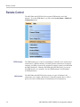


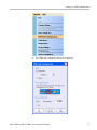


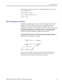


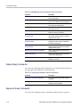
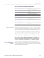
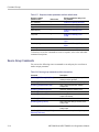


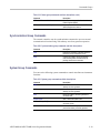
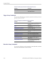


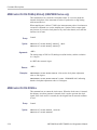


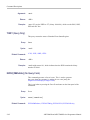

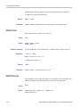
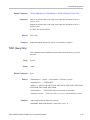


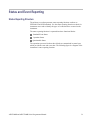
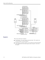
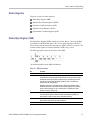

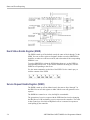
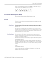
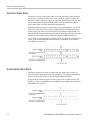
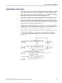

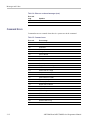


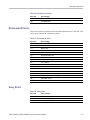


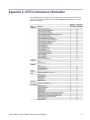
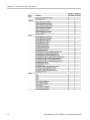
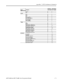


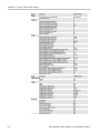

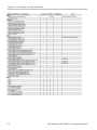
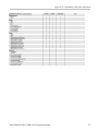


![[SOURce[1|2]]](http://vs1.manualzilla.com/store/data/006001849_1-f604f41c432649719bf8fb1e153f52f2-150x150.png)

![[SOURce[1|2]]](http://vs1.manualzilla.com/store/data/005803287_1-72ff358839cd16ae2e8c94de56269657-150x150.png)