1
engineering
mannesmann
Rexroth
Supply Module
KDV 2.3
Applications
DOK-POWER*-KDV*2.3****-ANW1-EN-P
264432
Indramat
About this documentation
Titel
Type of documentation:
Documenttype
Internal file reference
Reference
This documen2@ation
is used:
KDV 2.3 Supply module for AC drives
Applications
DOK-POWER*-KDV*2.3****-ANW1-EN-E1,44
• Mappe 6
• KDV23-AN.pdf
• 209-0049-4306-02
This electronic document is based on the hardcopy document with document
desig.: DOK-POWER*-KDV*2.3****-ANW1-EN-P • 02.97
In this document you will find:
• the range of applications,
• the electrical lay-out,
• the mechanical lay-out of the control cabinet,
• mounting and installation guidelines,
• guidelines for selecting additional components, and,
• troubleshooting guidelines.
Change procedures
Copyright
Designation of documentation
up to present edition
Release- Coments
date
DOK-POWER*-KDV*2.3****-ANW1-EN-P
Feb./97
New Edition
DOK-POWER*-KDV*2.3****-ANW1-EN-E1,44
Jun./97
2nd E-Dok
© INDRAMAT GmbH, 1994
Copying of this document, and giving it to others and the use or communication
of the contents thereof, are forbidden without express authority. Offenders are
liable to the payment of damages.
All rights are reserved in the event of the grant of a patent or the registration
of a utility model or design. (DIN 34-1)
The electronic documentation (E-doc) may be copied as often as needed if
such are to be used by the consumer for the purpose intended.
Validity
Publisher
All rights reserved with respect to the content of this documentation and the
availability of the products.
INDRAMAT GmbH • Bgm.-Dr.-Nebel-Straße 2 • D-97816 Lohr
Telefon 0 93 52 / 40-0 • Tx 689421 • Fax 0 93 52 / 40-48 85
Dept ENA (DE, FS)
• DOK-POWER*-KDV*2.3****-ANW1-EN-E1,44 • 06.97
2
Table of Contents
Table of contents
Page
1.
INDRAMAT's modular AC drive system
5
1.1.
The design of the KDV 2.3 supply module ...................................... 6
2.
Applications
2.1.
Functional power features of the KDV 2.3 ....................................... 8
2.2.
KDV 2.3 power ratings .....................................................................9
2.3
KDV 2.3 - technical data ................................................................ 10
3.
Guidelines for installation and electrical connections
3.1.
Terminal diagram ............................................................................12
3.2.
Mains connection - power section ..................................................13
3.3.
Fuse protection for the power connection ...................................... 14
3.4.
Selecting the mains contactor ........................................................14
3.5.
Power supply requirements ........................................................... 15
3.6.
DC bus ...........................................................................................16
3.7.
Additional capacitance on the DC bus ........................................... 17
3.8.
Smoothing choke ...........................................................................17
3.9.
Electronics and internal blower power supply ................................ 17
7
11
3.10. Wire-ribbon connection for the electronics and signal exchange .. 18
3.11. Fault current protective device .......................................................19
3.12. Checking the control cabinet ..........................................................19
3.13. KDV 2.3 from the front ...................................................................20
3.14. Installing the KDV 2.3 in the control cabinet .................................. 21
4.
Control circuits (control of input power)
4.1.
Differentiating features of the power circuits .................................. 25
4.2.
Using the DC bus dynamic brake ..................................................26
4.3.
DC bus short-circuiting switch ........................................................28
4.4.
KDV 2.3 control circuits with dynamic braking ...............................30
4.5.
KDV 2.3 control circuits without dynamic braking .......................... 32
4.6.
Control circuits for a controlled braking of the drives
for an E-stop or power failure ......................................................... 34
• DOK-POWER*-KDV*2.3****-ANW1-EN-E1,44 • 06.97
24
3
Table of Contents
5.
Interface descriptions
5.1.
Signal voltages ...............................................................................36
5.2.
Ready .............................................................................................36
5.4.
Feedback power too high ...............................................................37
5.3.
Electronics supply working .............................................................37
5.5.
Power supply working ....................................................................38
5.6.
Bringing the drives to a standstill with a fault in the
power supply system ......................................................................38
6.
Troubleshooting guidelines
6.1.
Troubleshooting .............................................................................40
6.2.
Diagnostics displays ......................................................................42
6.3.
Fault list and remedial actions .......................................................42
6.4.
Fuses .............................................................................................43
7.
Dimensional data
7.1.
KDV 2.3 supply module - dimensional data ................................... 44
7.2.
Dimensions: DST 3-phase AC autotransformer ............................. 45
7.3.
Dimensions: DLT 3-phase AC isolation transformer ...................... 46
7.4.
Dimensional data: CZ 1.02 additional capacitor ............................ 47
7.5.
Dimensional data: TCM 1.1 add. capacitor module .......................47
7.6.
Dimensional data: GLD 12/13 smoothing choke ...........................48
7.7.
Dynamic brake contactor ...............................................................49
7.8.
Dynamic brake resistor ..................................................................49
8.
Order details
8.1.
KDV type codes .............................................................................50
8.2.
Available versions ..........................................................................50
8.3.
Summary of the electrical connecting accessories ........................ 51
8.4.
Order details for mains supply with KDV 2.3 .................................51
9.
List of INDRAMAT service reps
52
10.
Index
54
• DOK-POWER*-KDV*2.3****-ANW1-EN-E1,44 • 06.97
36
40
44
50
4
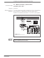
1. INDRAMAT's modular AC drive system
1.
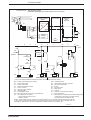
INDRAMAT's modular AC drive system
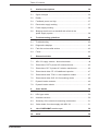
The modular INDRAMAT AC drive is made up of the following parts:
• control gears,
• a supply module, and,
• the drive modules,
which can be combined with each other components depending upon power
or functions wanted.
L1
L2
L3
3xAC
50 ... 60Hz
Input
power
Autotransformer
Power
contactor
Supply module (e.g., KDV 2.3)
Power
supply
- threephase bridge
- bleeder
- signal voltage
generation
Signal voltage
supply/monitoring
D.C. bus
Drive module
- control
- monitoring
- diagnosing
Power
electronics
Programming module
Drive
M
G
Feed motor
Encoder
FSAntrieb
Figure 1.1: The KDV 2.3 supply module as a part of INDRAMAT's AC drive system
• DOK-POWER*-KDV*2.3****-ANW1-EN-E1,44 • 06.97
5
1. The design of INDRAMAT's modular AC drive system
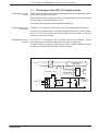
1.1. The design of the KDV 2.3 supply module
Power supply to the
drives
The threephase bridge rectifies the threephase mains AC voltage and provides
the DC high voltage for the drives.
When the drives are in generator-mode, the regenerated energy is absorbed
by the bleeder and transformed into heat.
The buffer capacitance provides sufficient smoothing.
Power supply to the
electronics
The KDV 2.3 provides the +24V and ±15V for all attached drive modules.
In the event of a power failure, the signal voltages receive their power from the
DC bus. This means that the drive electronics can still function, when the
drives are in generator mode.
Monitoring the drive
system
The KDV 2.3 is equipped with extensive monitoring functions. These
communicate with the drive modules via the signal voltage bus.
The Bb1 contact is of greater significance to drive system readiness. Power
can only be switched on when this contact is closed.
L1
230 V AC
L3
~
Supply and drive
monitoring
=
drives ready
smoothing choke
&
Bb1
supply ready
L1
3 x 230 V L2
L3
DC
300 V DC
to supply the
drives
DC
FSKDV23
Figure 1.2: The design of the KDV 2.3 supply module
• DOK-POWER*-KDV*2.3****-ANW1-EN-E1,44 • 06.97
6
2. Applications
2.
Applications
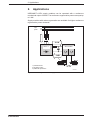
INDRAMAT's KDV supply modules can be operated with a continuous
mechanical output of 24 kW. The continuous regenerative power can equal up
to 2 kW.
Supply modules with mains regeneration are available for higher continuous
regenerative power demands.
Input
power
L1
L2
L3
1)
30 kW
KDV 2.3
drive modules
2)
3)
2 kW
Pm
1) autotransformer
2) smoothing choke
3) additional capacitance
Pm
24 kW
FSKDV23
Figure 2.1: Power range of a KDV 2.3 supply module
• DOK-POWER*-KDV*2.3****-ANW1-EN-E1,44 • 06.97
7
2. Applications
2.1. Functional power features of the KDV 2.3
• Simplified fusing
Only overload protection for the power supply line is needed. Commercial
power protection switches or slow-blow fuses can be used.
• Ground fault monitoring of the attached drives
In the event of a fault, power is immediately switched off by opening the Bb1
contact and signalled via the optical display on the LED.
• Drive system response to a power failure
Can be programmed by inserting the external NC bridge circuit:
– Without the NC bridge circuit, the drives will brake with maximum torque.
– With the NC bridge circuit, there is a signal to the NC control unit via a
potential-free contact. It makes it possible for the NC control unit to brake
the drive to a standstill, protecting expensive tools and workpieces
against damage.
• Limiting the charging current of the DC bus capacitors
The charging current need not be taken into consideration when selecting
the switching device for the power supply. The lifespan of the switching
devices is increased.
• High control voltage loads
Six drive modules can generally be mounted to one supply module.
• Ease of servicing
The signal lines are connected via plug-in terminal screws.
• Power ratings by means of additional components
Input power can be configured to meet the demands of the relevant
application.
• DOK-POWER*-KDV*2.3****-ANW1-EN-E1,44 • 06.97
8
2. Applications
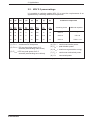
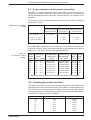
2.2. KDV 2.3 power ratings
It is possible to optimize usable KDV 2.3 to meet the requirements of an
application by combining additional components.
(1)
(2)
(3)
(4)
(5)
(6)
(7)
(8)
Additional components
PDC
kW
PKB-3
kW
PKB-03
kW
PBD
kW
PBM
kW
Wmax
kWs
Pm
kW
S
kVA
15
30
90
2
40
100
12
16
GLD 13
---
22
30
90
2
40
100
17,6
23
GLD 12
CZ 1.02
30
30
90
2
40
100
24
32
GLD 12
TCM 1.1-04
smoothing choke
additional capacitor
(1) PDC = continuous DC bus power
(4) PBD =
continuous bleeder power
(2) PKB-3= DC bus short-time power for 3
seconds (accelerating main drives)
(5) PBM = peak bleeder power
(3) PKB-03 = DC bus peak power for 0.3
seconds (accelerating servo drives)
(7) Pm =
continuous mechanical power
(8) S =
connected power
(6) Wmax = maximum regenerative energy
Figure 2.2: Typical KDV 2.3 power ratings by combining additional components
• DOK-POWER*-KDV*2.3****-ANW1-EN-E1,44 • 06.97
9
2. Applications
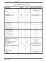
2.3
KDV 2.3 - technical data
Designation
Symbol
Unit
KDV 2.3-100-220/300-000
Nominal input voltage
UACN
V
3 x 230V (+10%; -15%) or
3 x 220V (+15%; -10%)
Frequency
fN
Hz
50...60
DC bus voltage
UDC
V
Continuous DC bus voltage
Pcont
kW
30 (with add. capacitance 4 mF)
Peak DC bus power
Ppeak
kW
90
Continous bleeder power
PBD
kW
2
Peak bleeder power
PBM
kW
40
Max. regenerative energy
W
kWs
100
Power loss inside the
control cabinet
Pv
W
150
Power loss outside the
control cabinet
Pv
W
500 (+bleeder-continous power)
Input - power section
Output - power section
300 (+ 15%; -10%)
KDV weight
m
kg
17
Weight of the mech. mounting accessories
m
kg
1.7
Weight of the LE3 blower
m
kg
4.2
+ 24 V on-load voltage
UL
V
22 to 26
+ 24 VL continuous current
IUL
A
11.5
%
2
Control voltage output
+ 24 VL ripple
± 15 V measuring voltage
UM
V
14.9 to 15.1
+ 15 VM continuous current
I+UM
A
2
- 15 VM continuous current
I-UM
A
2
%
0.1
± 15 VM ripple
Auxiliary voltage and blower power
Input voltage
UAC
V
230 (+10%;-15%)
Frequency
f
Hz
50 to 60
Auxiliary voltage power consumption
P
VA
500
Blower power consumption
P
VA
70 VA per heatsink
Blower voltage
UAC
V
230V (+10%;-15%) or 115V(±10%)
(depends on blower type)
Installation elevation without reduction of
nominal data
m
1000 meters above sea level
Permissible relative humidity
%
Permissible absolute humidity
Degree of contamination
g/m
maximum 95
3
25 g water / m3 air
- non-conductive contamination
- no condensation
Protection classification:
drive
IP 10 per DIN VDE 470, section 1
heatsink
IP 54
Figure 2.3: KDV 2.3 - technical data
• DOK-POWER*-KDV*2.3****-ANW1-EN-E1,44 • 06.97
10
3. Guidelines for installation and electrical connections
3.
Guidelines for installation and electrical
connections
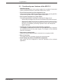
The following KDV 2.3 terminal diagram is a recommendation of the
manufacturer of the unit. The circuit diagrams of the machine
builder must be used for installation!
• DOK-POWER*-KDV*2.3****-ANW1-EN-E1,44 • 06.97
11
L1 L2 L3 PE
3xAC (50 - 60 Hz)
with mains-related
earth conductor
Q1
T1
• DOK-POWER*-KDV*2.3****-ANW1-EN-E1,44 • 06.97
K1
AC 115V or 230V per
blower version
Power voltage
monitoring
NC bridge for controlled
braking
Shield
Temperature warning
Ready status
Auxiliary voltage
Control voltage
for external
applications
Q2
3xAC
X9
L3
L2
L1
X13
X10
1
2
3
4
5
6
7
8
9
10
11
12
13
14
15
+15VM
0VM
-15VM
+24VL
0VL
Bb1
Bb1
NH
BVW
BVW
UD
UD
NCB
NCB
1/L1
2
3/L3
X10a
1L+ 2L+
1
X28
L1
2
stranded
F2
F4
F3
+/-15V
+24V
low-voltage power supply
PE
+L
X9
-L
X12
X14b
X14a
UD/1
Bb/2
+15VM/3,4
0VM/5,6,7,8
-15VM/9,10
+24VL/11,12
0VL/13,14
UESS/15
shield /16
X1
1L- 2L- X28a
smoothing choke
KDV 2.3 supply module
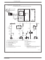
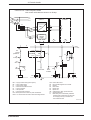
Risk of damage!
X10a: Attach connection 1/L1 to same phase as X9/L1
Attach connection 3/L3 to same phase as X9/L3
DC 300V
conductor rails
stranded
F6
M
unit blower
(3 pin
Indramat
cable)
external
heatsink
blower
Supply for
the drive
components
via the
electrical
connecting
accessories
> 15kW with D.C. bus
continuous power
additional capacitance
Signal processing
+/-15V; +24V
(16 pin bus cable)
- +
C1
3. Guidelines for installation and electrical connections
3.1. Terminal diagram
APKDV3.2
Figure 3.1: KDV 3.2 supply module connecting plan
12
3. Guidelines for installation and electrical connections
3.2. Mains connection - power section
Connection voltage
Frequency
Mains connection via
transformer
3 x AC 230 V (+10%; -15%) or
3 x AC 220 V (+15%; -10%)
50 to 60 Hz
The mains voltage can generally be adapted by using an autotransformer
(also see Section 3.5: "Requirements of the power supply system").
The KDV 2.3 can be directly connected to 3 x AC 220 V - power systems.
3 x AC 50...60 Hz
L1
L2
L3
PE
1
NC control unit
PE-busbar in the
control cabinet
NC
16mm 2
16mm 2
a
b
16mm 2
16mm 2
K1
2
supply
module
drive
module
drive
module
drive
module
1 + 2 stranded cable
diameter per EN 60 204 (VDE 0113)
NAKDV2.3
Figure 3.2: Connecting the KDV 2.3 to the mains via an autotransformer
Each drive module must be connected to the PE busbar of the KDV
2.3 by a separate ground conductor.
• DOK-POWER*-KDV*2.3****-ANW1-EN-E1,44 • 06.97
13
3. Guidelines for installation and electrical connections
3.3. Fuse protection for the power connection
The KDV 2.3 mains connection can be protected by using either circuit
breakers or gL classsification fuses (slow-blow). Using power circuit breakers
has the advantage that faulty operation, with two phases, for example, is not
possible.
The protective device is generally placed on the primary side if a matching
transformer is used.
Maximum permissible
fusing
Mains voltage
Nominal voltage fuse (gL) / power circuit breaker
connected without
matching transformer
connected with matching transformer
primary side
secondary side
3 x AC 220 V
IN = 80 A
---
---
upto 3 x AC 240 V
---
IN = 80 A
IN = 80 A
upto 3 x AC 525 V
---
IN = 63 A
IN = 80 A
Figure 3.3: Maximum permissible fusing
If an INDRAMAT transformer is used and all connections are executed as
outlined in section 3.2 then fuses and protective circuit breakers with a mains
voltage of 3 x AC 400 V can be used (see table below).
Fuses for
3 x AC 400 V mains
voltage
Transf.
Nominal (A)
power
current
(kVA) primary second.
10
12.5
15
18
20
25
35
1)
14.5
18.1
21.7
26.0
28.9
36.1
50.6
25.1
31.4
37.7
45.2
50.3
62.8
88.0
Recommended
fuses of the
gL type
20 A slow-blow
25 A slow-blow
25 A slow-blow
35 A slow-blow
35 A slow-blow
50 A slow-blow
63 A slow-blow
Siemens power
circuit breaker
3V..1) series
Setting Setting
range
range
(A)
(A)
3VU1300-•MP00
3VU1600-•MP00
3VU1600-•MP00
3VU1600-•MQ00
3VU1600-•MQ00
3VU1600-•MR00
3VF3111-5DN71
18 to 25
22 to 32
22 to 32
28 to 40
28 to 40
36 to 50
40 to 80
18
22
26
32
36
46
60
Maximum back-up fuse must be as per manufacturer's guidelines!
Figure 3.4: Fusing with 3 x AC 400 V mains voltage
3.4. Selecting the mains contactor
The following selection of transformers applies if power is connected on the
secondary side of the mains transformer (as per KDV 2.3 terminal diagram).
The choice must correspond to the nominal current of the secondary side of
the mains transformer. Peak making currents need not be considered because
of the KDV 2.3 charging current limitation.
Transformer power (kVA)
Secondary transf. nominal current (A)
10
12.5
15
18
20
25
35
25.1
31.4
37.7
45.2
50.3
62.8
88.0
Mains contactor from Siemens
3TF44
3TF46
3TF46
3TF47
3TF47
3TF47
3TF50
Figure 3.5: Selecting the mains contactor
• DOK-POWER*-KDV*2.3****-ANW1-EN-E1,44 • 06.97
14
3. Guidelines for installation and electrical connections
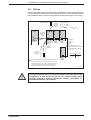
3.5. Power supply requirements
Grounded threephase
mains
Voltages can be adapted to grounded mains systems, either star systems with
a grounded neutral or a system with a grounded phase (TN or TT mains), by
using an autotransformer. The KDV 2.3 can be directly connected to 3 x AC
220 V mains.
Ungrounded
threephase mains
There is the increased danger in ungrounded mains (IT mains) that overvoltages
can occur between phases and housing. The KDV 2.3 should only be operated
with such systems, if:
• it is connected across an isolation transformer, or,
• the installation is protected with an overvoltage conductor.
Connecting the KDV 2.3 via an isolation transformer offers the best
protection against overvoltage and the greatest operating safety!
Permissible
overvoltage levels
The voltage levels between the outer conductors (L1, L2, L3, 1L1, 3L3) and
the KDV 2.3 housing can equal 230 V (effective).
Non-periodic overvoltages per VDE 0160 between phases and housing are
permissible for the KDV 2.3 (see following diagram).
UN+∆U
UN
3
2.6
∆U
2
1.8
T
UN
1.6
∆U
2
2.4
2.3
2.2
1.4
1.2
1.15
1.1
1
0.1
0.2
0.4 0.6
1 1.3
2
4
6 10
T (ms)
20
3_05DGUEBSPG
Figure 3.6: Permissible non-periodic overvoltages per VDE 0160
The KDV 2.3 can be connected to 3 x AC 230 V - input power systems.
This means that the maximum permissible, non-periodic overvoltage may
equal: 230 V x √ 2 x 2.3 = 745 V.
• DOK-POWER*-KDV*2.3****-ANW1-EN-E1,44 • 06.97
15
3. Guidelines for installation and electrical connections
3.6. DC bus
Use the busbars found in the connection accessories of the drive module to
connect the drive modules to the DC bus of the KDV 2.3. Use individual cables
with stranded wires for longer connections (maximum length is one meter).
smoothing choke
TCM
L-
additional
module
and PDC < 23 kW
35 mm2 for PDC > 23 kW < 30 kW
L-
L-
L-
L+
L+
L+
drive
module
drive
module
KDV 2.3
1
16 mm2 for GLD 13
25 mm2 for GLD 12
1L+ 2L+
stranded,
maximum
length 1
meter
16 mm2
L+
stranded,
maximum
length 1
meter
stranded,
max.
length
one meter
Diameter depends on
continuous D.C. bus voltage
to-be-transmitted, at least
16 sq. mm
K2
D.C. bus
dynamic
braking
1
R1
If fusing corresponds to recommendations in Sect. 3.3:
stranded,
maximum
length 1
meter
L-
PDC in kW
L+
18
23
A in mm2
16
25
drive
module
Mains transformer up to 25 kVA: diameter = 10 mm2
Mains transformer up to 35 kVA: diameter = 16 mm2
(A stud is needed to connect these diameters to K2.
Supplier: Telemecanique, part no. LA9 - D 2561)
TVMZwkreis
Figure 3.7: DC bus wiring
During normal operation, the dynamic brake resistor R1 has DC 300
V applied to it with respect to ground! The cabinet builder must
provide protection against accidental contact (plexiglass or
perforated sheeting, for example).
• DOK-POWER*-KDV*2.3****-ANW1-EN-E1,44 • 06.97
16
3. Guidelines for installation and electrical connections
3.7. Additional capacitance on the DC bus
It is possible to connect additional capacitors (CZ 1.02) or additional capacitance
modules (TCM) to the DC bus to increase the capacity of the KDV 2.3.
Increasing power
Energy capacitor for
power failures
An additional capacitance of 4 mF is needed to utilize this.
In a few applications, it might be necessary for the drives to back up in the event
of a power failure. The energy stored in the DC bus can be used for this action.
The DC bus capacity can be increased with the use of additional capacitors.
A maximum of 8 mF additional capacitors may be connected. Each mF of
additional capacitance can store up to 30 Ws.
3.8. Smoothing choke
The KDV 2.3 must be operated with a smoothing choke in the "L+ line" from
a DC bus load of 9Kw:
DC bus load
Smoothing choke required
(see Section 7.6 for technical data)
up to 9 kW
up to 15 kW
greater than 15 kW
none
GLD 13
GLD 12
Figure 3.8: Required smoothing choke
3.9. Electronics and internal blower power supply
Electronics supply
Supply terminal:
Terminal diameter:
Terminal voltage:
Terminal capacity:
X10a/1 - X10a/3
maximum 1.5 mm2
AC 230 V; 50 to 60 Hz
500 VA (if electronics supply reaches maximum
load)
Circuit breaker 10 A (tripping characteristic C:
magnetic release between 7 to ten times rated
current)
Recommended fusing:
Tap electronics power off of outer conductors L1 and L3 of the
power source (see terminal diagram in Section 3.1). NOTE: X10a/
1 and X9/l1 must have the same phase, and X10a/3 and X9/L3 must
also have same phase! The KDV 2.3 could otherwise be damaged!
External blower supply
Supply terminal:
Terminal diameter:
Terminal voltage:
Terminal capacity:
X13
maximum 1.5 mm2
LE3-220 blower: AC 220/230 V; 50 to 60 Hz
LE3-115 blower: AC 110/115 V; 50 to 60 Hz
70 VA for each blower
• DOK-POWER*-KDV*2.3****-ANW1-EN-E1,44 • 06.97
17
3. Guidelines for installation and electrical connections
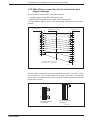
3.10. Wire-ribbon connection for the electronics and
signal exchange
The wire-ribbon connection X1 has two functions:
• supplying power to the drive electronics, and,
• signal exchange between the supply and drive modules.
The wire-ribbon cable is part of the connecting accessories of the drive
module.
Connector X1 (1)
Connector X1 (2)
Wire-ribbon connection
1
2
3
4
5
6
7
8
9
10
11
UD
UD
BB
BB
+15V
+15V
0VM
+15V
0VM
0VM
0VM
0VM
0VM
0VM
-15V
0VM
-15V
-15V
0VL
-15V
+24V
+24V
+24V
12
0VL
0VL
n.a.
(1) Connector X1 for 12 pin units
(2) Connector X1 for 16 pin units
1
2
3
4
5
6
7
8
9
10
11
12
13
14
15
16
Bus12_16
Figure 3.9: Wire-ribbon for transition from 12-pin to 16-pin connector
The wire-ribbon connection receives a terminal connector. It is used to verify
the connections. This terminal connector is part of the KDV 2.3 mounting
accessories. If no terminal connector is installed, the Bb1 contact of the power
supply will not close.
2
3
2
3
10
11
12-pin terminal
connector
16-pin terminal
connector
Endstecker
Figure 3.10: Terminal connector for the wire-ribbon connection
• DOK-POWER*-KDV*2.3****-ANW1-EN-E1,44 • 06.97
18
3. Guidelines for installation and electrical connections
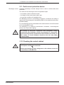
3.11. Fault current protective device
Discharge current
Capacitive discharge currents always flow to earth in switch-mode drive
controllers.
The extent of the discharge current is dependent upon:
• the number of drive controllers used,
• the length of the motor power cable, and,
• the ground conditions at installation site.
The discharge current is unavoidably increased, if measures are taken to
improve the electromagnetic compatibility (EMC) of the machine (mains filter,
shielded cables).
FI-current limiting type circuit breakers with a nominal fault current of less than
0.3 A should not be used!
The switching on of inductors (transformers, contactors, electromagnetic
values) can cause false tripping.
The safety of electronic equipment with threephase bridge
connections (B6 switches) cannot be guaranteed if commercial,
pulse-current sensitive FI protective circuit breakers are used. For
this reason, FI circuit breakers should not be the only safety
measure taken.
3.12. Checking the control cabinet
Only those voltages outlined in the data sheets or in the interface
descriptions should be connected!
Before performing any high voltage test on the cabinet, remove all
connections to the KDV 2.3!
• DOK-POWER*-KDV*2.3****-ANW1-EN-E1,44 • 06.97
19
3. Guidelines for installation and electrical connections
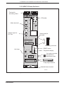
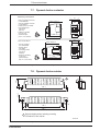
3.13. KDV 2.3 from the front
Terminal for
smoothing choke
X28
X28 a
X12
PE busbar
L1
Mains terminals
X12 a
L2
L3
L-
Voltage output for
D.C. bus
Terminal strip for
bus cable
L+
X9
AC
SERVO
2
3
POWER SUPPLY
X1
SN240060-02029 A01
RESET
S2
Terminating connector
RESET button
Unit fuses
F3
F4
Diagnostics display
F2
X10 a
X10
3 pin plug-in terminal
for electronics
and blower power
15 pin plug-in terminal
Heatsink blower terminal
X13
X14
FAKDV23
Figure 3.11: KDV 2.3 from the front
• DOK-POWER*-KDV*2.3****-ANW1-EN-E1,44 • 06.97
20
4xø5
11
351 +1
15
373 ±0,2
• DOK-POWER*-KDV*2.3****-ANW1-EN-E1,44 • 06.97
50 +1
115
=
=
18
86 +1
=
2xø11
6xø5
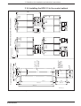
Panel cut-out for
outer blower is
only required in
units with forced
cooling.
Panel cut-out
for
KDS, KDV and
KDA modules
clearance
96 ±0.2
78 ±0.2
92
=
clearance
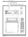
View from inside the control cabinet
KD.
110 ±0.5
KDV 2.
200 ±0.5
KDA 2.
KDA 3.
KD.
TDM.
DDS2.
KDV 2.
155 ±0.5
KDA 2.
KDA 3.
TDM
3.
4.
DDS
3
KDA 2.
KDA 3.
137 ±0.5
110 ±0.5
KDV 3.
110 ±0.5
KDV 2.
KD.
155 ±0.5
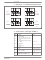
KDV module arrangement in the control cabinet
KDA 2.
KDA 3.
110 ±0.5
Minimum clearance
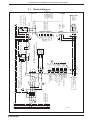
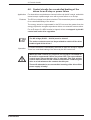
3. Guidelines for installation and electrical connections
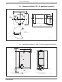
3.14. Installing the KDV 2.3 in the control cabinet
555
100
9
133 ±0.2
403 ±0.2
KDV/Teilung.fh3
Figure 3.12: Panel cut-outs and dimensions
21
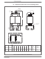
hexagon socket
with SW5
Note conductive connections
on backwall of control cabinet
and
mounting frame!
• DOK-POWER*-KDV*2.3****-ANW1-EN-E1,44 • 06.97
Cap screw / 4x
M4x18Z4-1 DIN912 (1)
5
Finger guard
109-0575-3236-XX (1)
Mounting frame for K-module
109-0575-4831-XX (2)
Clearance to flammable
materials or parts which can
be affected by heat:
at least 300 mm!
Mounting frame for blower
109-0575-4833-XX (1)
Those parts labelled with (2) are in
of accessories kit M1 - 109-0575-4851-XX.
KDV2/Montage.fh3
Backwall of cabinet
Housing and control cabinet design
see drawing 109-0574-3004-XX
Panel cut-out for additional blowers
M4 thread
18
69
Bleeder safety hood
109-0574-4820-XX
must always be mounted to
protect personnel and unit!
Those parts labelled with (1) are a part
of blower assembly 109-0574-4819-XX.
Cap screw / 2x
M4x14Z4 DIN912 (1)
Blower for forced cooling
109-0575-4832-XX (1)
Only to be used in units with W1 cooling modes.
See description of KDV.
e
as
ph
e
e
ule
r
Th V mod
D
K pply
su
(2) M4/4x contact disc
Cap screw / 4x
M4x16 DIN912 (2)
Panel for additional K-modules
M8 thread
3. Guidelines for installation and electrical connections
Figure 3.13: Mounting the KDV 2.3 into the control cabinet
22
3. Guidelines for installation and electrical connections
Heat loss
Heat loss occurs when the KDV 2.3 is operated. This is caused by basic losses
during signal voltage generation, power losses and by energy transformation
in the bleeder.
The heatsink, which conducts this heat loss, is mounted to the back of the KDV
2.3. This means the KDV 2.3 is mounted with the heatsink sticking out of the
back of the control cabinet.
Note that the heatsink must maintain a safety clearance of 30 cm
from flammable materials or parts which could be affected by heat!
The heat loss occurring within the control cabinet can be reduced to about
150 W with the above mounting mode. This means that more compact control
cabinets can be built. It also eliminates or minimizes the additional work due
to control cabinet air conditioning.
PVint
PVext
external
internal
Heat loss in the control
cabinet
air duct
Heat loss
Q
= 32 l/s
Pmax = 50 Pa
Vair = 3...4 m/s
KD...
heatsink
blower motor
completely sealed housing or
cabinet
heatsink blower
air current
Kühlart
Figure 3.14: A break down of the heat losses
Cooling with a heatsink
blower
A bleeder cover SH-KD ist needed for the air duct and to cover the bleeder.
The heatsink blower can be ordered, with accessories, using order no. LE3... (LE3-220 with 220 V, LE3-115 with 115 V).
Cooling with a central
blower
If several heatsinks are cooled in a common air duct with only one central
blower used, then make sure that there is sufficient air! Check air stream Q!
• DOK-POWER*-KDV*2.3****-ANW1-EN-E1,44 • 06.97
23
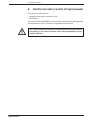
4. Control circuits
4.
Control circuits (control of input power)
The control circuits relate to
• switching input power on and off, and,
• the E-Stop.
The control circuits INDRAMAT recommends illustrate the operating principle.
Several different control circuits are suggested in this section.
The control scheme selected and its effect depends on the features
and timing of the entire machine and is the responsibility of the
machine builder.
• DOK-POWER*-KDV*2.3****-ANW1-EN-E1,44 • 06.97
24
4. Control circuits
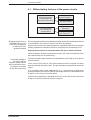
4.1. Differentiating features of the power circuits
Bringing the drives
to a standstill with
faulty drive electronics
controlled braking
for an E-Stop or
a power failure
with D.C bus
dynamic braking
without DC bus
dynamic braking
by the drive
electronics
by the
NC control unit
Figure 4.1: Differentiating features of the power circuits
Bringing the drives to a
standstill with an error
in the drive electronics
or without DC bus
dynamic braking
DC bus dynamic braking is an additional safety factor when braking the drives
to a standstill in the event of a fault in the drive electronics.
Synchronous motors are always braked to a standstill with DC bus dynamic
braking regardless of whether the drive electronics are functioning or not.
Asynchronous drives do not brake when DC bus is short-circuited!
Without dynamic braking synchronous motors will coast uncontrolled if the
drive electronics are not functioning.
Controlled braking of
the drives with an
E-Stop or power failure
with command-to-zero,
or position controlled
by the NC control unit
The drive control brings the drives to a standstill for an E-stop or as a result of
a power failure.
In the event of an E-stop or if the drive-internal monitor is tripped, the drive
control will switch velocity to zero. The drives brake uncontrolled at maximum
torque.
It is necessary with some applications (e.g., electronically-coupled gear
cutting machines) that the NC control unit brings the drive to a standstill in an
E-stop or in the event of a power failure.
The drives are braked to a standstill by the NC control unit in the event of an
E-stop or if the drive-internal monitor is tripped.
• DOK-POWER*-KDV*2.3****-ANW1-EN-E1,44 • 06.97
25
4. Control circuits
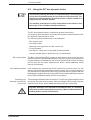
4.2. Using the DC bus dynamic brake
The best way to bring the drives to a standstill with a fault depends
on the drive equipment used and the features of the machine. The
following recommendations should, therefore, only be viewed as a
support for the machine builder.
The machine manufacturer is fully responsible for the features and
the scope of the individual safety mechanics!
The DC bus dynamic brake is intended to protect the machine.
A few typical (fault) situations are used in this section to explain when the DC
bus dynamic brake should be used.
The following (fault) situations serve as examples:
• Bb1 contact open
• limit switch open
• following error signal from the NC control unit
• E-stop actuated
• light barrier, safety door or step-pad contact activated
• operator enable switch ("dead man key") is deactivated
Bb1 contact open
The Bb1 contact of the KDV 2.3 opens in the presence of an error in the drive
electronics or interrupted feedback lines. In this case, synchronous drives can
only be braked to a standstill by the DC bus dynamic brake! Short-circuiting
the DC bus will not brake asynchronous drives. Mount additional safety
devices if necessary!
Limit switch activated
Limit switches are activated by the NC control unit or drive errors. For this
reason, the DC bus dynamic brake should be used. The overtravel distances
set (limit switch for the machine limit stop) must therefore be greater than the
braking path needed. Short-circuiting the DC bus will not brake asynchronous
drives. Mount additional safety devices if necessary!
Following error
message from the NC
control unit
This message indicates a fault in the drive. The DC bus dynamic brake should
be used in this case for this reason. Short-circuiting the DC bus will not brake
asynchronous drives. Mount additional safety devices if necessary!
Dynamic braking is not required for the above errors, if a coasting
of the drives cannot damage the machinery. Motors with mechanical
holding brakes can be an alternative.
• DOK-POWER*-KDV*2.3****-ANW1-EN-E1,44 • 06.97
26
4. Control circuits
E-Stop button, light
barrier, safety door,
step-pad contacts
tripped or pendant
enable deactivated
These monitoring devices serve to protect personnel. The drive equipment of
the machine must be taken into consideration for the error responses in this
case:
Machines with modular asynchronous drives
The danger caused by a main spindle drive of a tooling machine coasting
uncontrolled (usually asynchronous drives) is greater than the danger from the
uncontrolled coasting of a feed drive (usually synchronous drives).
If the referenced monitoring devices are tripped, then both the mains contactor
and the drive enable signal should be switched off. The DC bus voltage must
not be short-circuited because asynchronous drives cannot otherwise be
braked to a standstill.
Machines with modular synchrous drives (e.g., handling systems)
Switching off the mains contactor and removing the drive enable achieves the
shortest possible braking distances with intact drives. Only if the energy stored
in the DC bus capacitors can initiate dangerous drive movements, must the
dynamic brake be used with a fault.
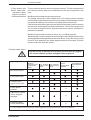
Pendant enable button
Dynamic brake contactors and resistors are not suited for jogging.
The control cabinet could be damaged if this is ignored!
Input signal
Existing drive equipment
modular
asynchrous and
synchronous
drives
only modular
synchronous
drives
Recommended response
only modular
asynchronous
drives
DC bus
dynamic brake
activated
drive enable and
mains contactor
OFF
Bb1 contact open
Limit switch open
Following error
signal from the NC
E-stop button
pressed
1)
Light barrier, safety
doors, step pad
actuated
1)
Pendant enable
button deactivated
1)
1) Only if dangerous drive movements can be triggered by energy still present in the DC bus capacitors.
Figure 4.2: When to use the DC bus dynamic brake
• DOK-POWER*-KDV*2.3****-ANW1-EN-E1,44 • 06.97
27
4. Control circuits
4.3. DC bus short-circuiting switch
The DC bus short-circuit switch recommended by INDRAMAT is conceived to
protect either machine or plant against damage in the event of a drive failure.
This can be used to brake motors with permanent magnetic excitation even
in the event of drive control failure. This function cannot, however, be the only
safety device used to protect personnel.
Circuit design
This DC bus short-circuit contactor can switch the "short-circuit current" on but
not off. The DC bus short-circuit contactor may not be re-applied, once
released, until the DC bus has discharged. The following recommended
circuits (section 4.4) will make interference-free operations possible.
Programming the PLC appropriately does not guarantee the correct switching
sequence. The varying contactor actuating times can possibly trigger the
mains contactor before the DC bus short-circuit contactor is opened. This
means that the mains contactor should additionally be locked by means of an
auxiliary contact of the DC bus short-circuit contactor.
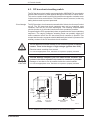
The DC bus short-circuit resistor is not secured against accidental
contact. There is the danger of high-voltages (greater than 50 V).
DANGER
Electrical shock resulting from contact
==> use an appropriate cover, see that it is in place or properly mounted
Thermal damage caused by DC bus short-circuit contactor and
resistor in the event of faults in the control or contactor is possible.
Damage or loss due to fire is possible inside the control cabinet.
CAUTION
==> use an appropriate cover, see that it is in place or properly mounted
130
275
min. 50
DC bus
shortcircuit
contactor
0
17
0
cable
routing
from below
DC bus
short-circuit
resistance
15
Minimum distance
to the front
Cover
AbdKDV23
Fig. 4.3: Suitable covers and unit arrangements for the DC bus short-circuit
• DOK-POWER*-KDV*2.3****-ANW1-EN-E1,44 • 06.97
28
4. Control circuits
Switching frequency
A maximum of six switching procedures is permitted per minute.
The number of possible switching sequences is reduced if the sum of the
rotary drive energy and the energy stored in the additional capacitance is
greater than 1500 Ws. Otherwise, the DC bus short-circuit resistor will be
overloaded. The number of the permissible DC bus short-circuit actuations
can be calculated as follows:
S=
S
=
Wrot =
WZK =
Service life
Maximum drive torque
s
min
+ W ZW )
150W ⋅ 60
(W rot
number of permissible actuations per minute (max. 6)
energy content of the drive given in Ws
energy stored in the additional capacitance given in Ws
The DC bus circuit contactor has a service lifespan of 20,000 actuations.
Once the DC bus is short circuited, the drive will be decelerated with the shortcircuit torque. This torque may be higher than the maximum torque indicated
in the selection list. Particularly, if the relationship maximum torque to shortterm operating torque is less than 1.3, then there will probably be increased
torque.
Increased torque with short-circuited DC bus is possible.
Damage to mechanical transmission parts, machine damage from
dimensional shifting that has gone unnoticed.
CAUTION
==> mechanical transmission elements must be laid out in terms of the
torque at with a short-circuited DC bus.
A list of the short-term torque for MDD motors can be requested. The following
formula can be used to calculate maximum torque with a short-circuited DC
bus.
MZK =
Km2 ⋅ ω
(RA + R ZK ) 2 + (ω pLA ) 2
MmaxZK = MZK + MH
MmaxZK
MZK
MH
Km
ω
RA
RZK
p
LA
=
=
=
=
=
=
=
=
max . drive torque with short-circuited DC bus
short-circuit torque in Nm
decel torque of the holding brake in Nm
current torque or voltage constant in Vs/rad
angle speed in rad/s
winding resistance of the motor in Ω
DC bus short-circuit resistance in Ω (2.2 Ω)
number of pole pairs; for MAC and MDD the following applies:
size ≤ 41; p = 2
size ≥ 63; p = 3
= winding inductance of the motor in H
• DOK-POWER*-KDV*2.3****-ANW1-EN-E1,44 • 06.97
29
4. Control circuits
4.4. KDV 2.3 control circuits with dynamic braking
Application
Modular synchronous motors are used.
This control circuit achieves a high degree of safety at low cost. The
monitoring capabilities built into the drive system are most effectively
implemented.
Typical applications:
• the KDV 2.3 is only supplying feed drives, and,
• if asynchronous main drives and feed drives are being operated by the same
KDV 2.3.
Features
Dynamic braking always stops synchronous motors whether the drive
electronics are functioning or not.
Dynamic braking is only activated for drive faults. If the E-stop monitor is
tripped, then drives are stopped under drive regulation at maximum torque.
There is a controlled braking of the drives under drive regulation at
maximum torque with either an E-stop, or if the KDV 2.3 monitors are triggered
(e.g., as the result of a power failure).
The NC bridge (X10/13 - X10/14) must not be closed!
Operation
The mains contactor drops out immediately when the E-stop button is pressed.
An auxiliary contact on the mains contactor switches the drive enable signal
off. Drive internally, the velocity command is switched to zero in all drives.
There is a controlled braking of all drives.
A drive fault message from the KDV 2.3 (Bb1 contact), a fault signal from the
NC control unit (servo error), or the tripping of an axis travel limit switch results
in the mains contactor being switched off and the activation of dynamic
braking.
• DOK-POWER*-KDV*2.3****-ANW1-EN-E1,44 • 06.97
30
4. Control circuits
Control circuit: • with dynamic brake
• controlled braking by the drive electronics in an E-stop
L1
L2
L3
Q10
T1
F1
L1
L2
L3
additional
drive
modules
Drive module
Supply module
KDV 2
Leistungsteil
L-
L-
L-
L+
L+
L+
RK
K1
L1
L3
F2
1
3
2
4
R4
Bb
Bb
7
6
8
9
10
+24V
+/- 10%
X10/6
S2
end
position
KDV/Bb1
NC
S4
OFF
RF
b
Y1
U
K1
RF
drive
module
K2
K1
T1
1) K4
S3
S5
ON
a
K1
X10/7
S1
E-Stop
K2
R2
K10
K3
K2
R3
K2
control
voltage
supply
5
R1
K3
U
Bb
K4
K4
U
U
K10
K4
0V
1) Only in the holding brakes of feed drives that are not controlled by the drive module.
Bb1 = supply module ready (drive system)
Bb = drive module ready
F1 = power supply fuses
F2 = electronics and blower fuses
K1 = mains contactor
K2 = dynamic brake contactor
K3 = decoupling Bb1
K4 = holding brake control
K10 = decouple thermal contact for power transformer
NC = error signal from the control
- open for fault drive (servo error)
- closed for E-Stop
Q10 = mains disconnect
RF = drive enable signal from controller
RK = dynamic brake resistor
S1 = E-stop
S2 = axis limit switch
S3 = safety doors
S4 = power off
S5 = power on, cancel dynamic braking
T1 = power transformer
Y1 = Take delay time of electrically released holding brake
of feed axes in account! Do not apply velocity
command until 100 ms after RF-ON.
NOTE! After K2 drops out, the contact must not be switched on for 0.5 seconds. Opening and closing of K2 due
to S2 or K2 being activated intermittently must absolutely be prevented, otherwise K2 may be damaged. After it is
switched off, contactor K2 must only re-energized by a defined command, for example, S5.
SSKDV2.3/1
Figure 4.4: Control circuits without soft-start resistor with dynamic braking
• DOK-POWER*-KDV*2.3****-ANW1-EN-E1,44 • 06.97
31
4. Control circuits
4.5. KDV 2.3 control circuits without dynamic braking
Application
When an uncontrolled coasting of the drives cannot damage the machine.
Typical applications:
• if the KDV 2.3 supplies only asynchronous drives, and,
• if the end position of the feed axis has been sufficiently damped.
The DC bus voltage is not short-circuited. Asynchronous drives are not braked
by dynamic braking in the presence of a drive fault. There can be no controlled
braking of the drives if the dynamic brake is applied.
Features
There is a controlled braking of the drives under drive regulation at
maximum torque with either an E-stop or if the KDV monitors are tripped.
The NC bridge (X10/13 - X10/14) must not be closed!
Operation
The mains contactor immediately drops out when the E-stop button is pressed.
An auxiliary contact on the mains contactor switches the drive enable signal
off. Drive internally, the velocity command is switched to zero in all drives.
Dynamic braking can only be dispensed with if the uncontrolled
coasting of the drives cannot damage machinery.
Motors with mechanical holding brakes can be an alternative.
• DOK-POWER*-KDV*2.3****-ANW1-EN-E1,44 • 06.97
32
4. Control circuits
Control circuit: • without dynamic brake
• controlled braking by the drive electronics in an E-stop
L1
L2
L3
Q10
T1
F1
L1
L2
L3
additional
drive
module
drive module
Supply module
KDV 2
power
section
Leistungsteil
L-
L-
L-
L+
L+
L+
K1
L1
L3
F2
1
control
voltage
supply
3
2
Bb
4
Bb
5
6
7
K3
S2
end
position
S1
E-Stop
+24V
+/- 10%
X10/6
KDV/Bb1
a
K1
T1
X10/7
1) K4
S4
OFF
NC
RF
b
Y1
U
S5
ON
K1
K1
K10
RF
drive
module
K3
U
Bb
K4
K4
U
U
K10
K4
0V
1) Only for feed drive holding brakes which are not controlled by the drive module.
Bb1 = supply module ready (drive system)
Bb = drive ready contact of drive module
F1 = fuse for input power
F2 = electronics and blower fuses
K1 = mains contactor
K3 = decoupling Bb1
K4 = holding brake control
K10 = decouple thermal contact for power transformer
NC = error signal from the control
Q10 = mains disconnect
RF = drive enable signal from controller
S1 = E-Stop
S2 = axis limit switch
S4 = power OFF
S5 = power ON
T1 = power transformer
Y1 = Take delay time of electrically released holding brake
of feed axes into account! Do not apply velocity
command until 100 ms after RF-ON!
SKDV23/2
Figure 4.5: Control circuits for KDV 2.3 without dynamic braking
• DOK-POWER*-KDV*2.3****-ANW1-EN-E1,44 • 06.97
33
4. Control circuits
4.6. Control circuits for a controlled braking of the
drives for an E-stop or power failure
Application
For those drives coupled as an electronic drive via the NC control, and which
cannot accept a phase-angle error with a power failure or an E-stop.
Features
The DC bus voltage is not short-circuited. This means that power is available
for a controlled braking of the drives.
The energy stored or regenerated in the DC bus must be greater than the
energy required to energize asynchrous drives or to execute a return action.
For an E-stop or if a KDV monitor is tripped, drives are stopped by the NC
control unit under drive regulation.
The NC bridge (X10/13 - X10/14) must be closed!
The mains contactor must not be permitted to switch off the drive
enable signal of the drives !
Operation
The mains contactor is immediately switched off when the E-stop is tripped.
There is a controlled braking of the drives by the NC control unit.
When the NCB contacts are jumpered, the signal for command-tozero will be suppressed if there is a power fault. The superordinate
control must assure that the drive is stopped. This high priority
control must monitor the UD contact of the KDV 2.3 and bring the
drive to a halt whenever the contact should open.
There will otherwise be an uncontrolled coasting of the drives if the
power supply is faulty!
• DOK-POWER*-KDV*2.3****-ANW1-EN-E1,44 • 06.97
34
4. Control circuits
Control circuit: • without dynamic brake
• NC control unit brakes the drives in an E-Stop
L1
L2
L3
Supply module
KDV 2
Q10
additional drive
modules
drive module
Leistungsteil
power
section
T1
F1
L1
L2
L3
L-
L-
L-
L+
L+
L+
K1
L1
L3
F2
control
voltage
supply
Bb
NCB NCB
1
3
2
Bb
5
4
6
7
K3
S2
end
position
X10/6
KDV/Bb1
X10/7
S1
E-stop
X10/11
UD
a
RF
T1
X10/12
K4
S4
OFF
+24V
+/- 10%
b
K10
Y1
U
S5
ON
K1
K1
control unit
K3
RF
drive
module
Bb
K4
U
K4
U
U
K10
K4
0V
PE
Bb1 = supply module ready (drive system)
Bb = drive module ready
F1 = power supply fuses
F2 = electronics and blower fuses
K1 = mains contactor
K3 = decouple Bb1
K4 = dynamic brake contactor
K10 = decouple thermal contact of power transformer
NCB = no command-to-zero with a fault if NC bridge closed
Q10 = mains disconnect
RF = drive enable signal from controller
S1 = E-Stop
S2 = limit switch
S4 = power OFF
S5 = power ON
UD = message from KDV "power feed OK"
T1 = power transformer
Y1 = Take delay time of electrically released
holding brake of feed axes into account!
Do not apply velocity command until
100 ms after RF-ON!
SKDV23.fh3
Figure 4.6: Control circuits for a controlled braking with an E-Stop or power failure
• DOK-POWER*-KDV*2.3****-ANW1-EN-E1,44 • 06.97
35
5. Interface descriptions
5.
Interface descriptions
5.1. Signal voltages
Signal voltages
The signal voltages can be tapped off of terminal strip X10. These terminals
are for measuring and test purposes. If these voltages are used out of the KDV,
then make sure that no interference voltages are coupled in (use short,
shielded cables).
Do not exceed the load capacity of the signal voltage outputs to ensure proper
operation of the drives! The ±15 VM are short-circuit-proof. The +24VL are
protected by fuse F2.
Terminal
Voltage
Note
X10/1
+15VM
maximum measuring voltage 100 mA
X10/2
0VM
measuring voltage reference potential
X10/3
-15VM
maximum measuring voltage 100 mA
X10/4
+24VL
maximum load voltage 2A
X10/5
0VL
load voltage reference potential
Figure 5.1: Signal voltages on X10
5.2. Ready
Bb1 contact
Output Bb1, terminal X10/6 - X10/7
Potential-free contact, maximum load DC 24V/1A
Operating
status:
no power to
the electronics
fault in the KDV 2.3
or in the drive
ready
Output
open
open
closed
The Bb1 contact of the KDV 2.3 has a superordinate significance.
The E-stop chain of the drive system is tied into the Bb1 contact.
Only when it is closed may threephase AC power be applied!
The Bb1 contact closes when power for the electronics is applied to X10 and
there is no fault.
The Bb1 contact opens for the following faults:
•
•
•
•
•
•
•
•
tachometer fault
overtemperature in the drive modules
drive module bridge fuses
a fault in the ± 15VM / +24VL signal voltages
an open wire-ribbon connection or missing termination connector
the heatsink temperature of the KDV 2.3 is too high
ground short in drive system
bleeder overload
• DOK-POWER*-KDV*2.3****-ANW1-EN-E1,44 • 06.97
36
5. Interface descriptions
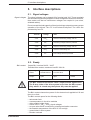
5.3. Electronics supply working
Output NH
Transistor output NH, terminal X10/8
Maximum load DC 24V/100mA
Operating
status:
no power to
the electronics
fault in auxiliary
voltage, DC bus
voltage functional
auxiliary voltage
functional
Output
high-resistance
low-resistance
high-resistance
external protective circuits
X10/4
+24V L
KDV 2.3
ϑ
R >= 240 Ω
NH
5.6 Ω
X10/8
0VL
SPKDV23NH
Figure 5.2: Protective circuit of the NH transistor output
5.4. Feedback power too high
BVW contact
Output BVW, terminal X10/9 - X10/10
Potential-free contact, maximum load DC 24V/1A
Operating
status:
no power to
the electronics
too high
Output
open
open
feedback power
acceptable
closed
The bleeder warning contact opens if feedback power is greater than 80% of
continuous bleeder power. If the bleeder load should continue to the rise to the
point of thermal overload, then the Bb1 contact will interrupt power flow. The
response of the drive system to this fault depends on the "NC" bridge (see
section 5.6).
• DOK-POWER*-KDV*2.3****-ANW1-EN-E1,44 • 06.97
37
5. Interface descriptions
5.5. Power supply working
UD contact
Output UD, terminal X10/11 - X10/12
Potential-free contact, maximum load DC 24V/1A
Operating
status:
no power to
the electronics
faulty
Output
open
open
power supply
functional
closed
The UD contact acknowledges that the power supply system is working.
It opens for the following faults:
• mains or phase failure, or,
• the DC bus voltage is less than 200 V
The response of the drive system to these errors depends on the NC bridge
(see section 5.6).
If an NC controlled braking becomes necessary, then the drives
must be braked to a standstill by the superordinate NC control unit
when the UD contact opens!
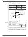
5.6. Bringing the drives to a standstill with a fault in
the power supply system
NC bridge
NC bridge, terminals X10/13 - X10/14
Open
Given a fault in the power supply and within the drive systems, the velocity
command of all connected drives is switched to zero if the NC bridge is open.
The drives are braked at maximum torque. In the presence of a drive fault, the
Bb1 contact additionally switches off the power.
Closed
If the NC bridge is closed, then the command-to-zero is suppressed with the
following faults:
• fault in the power supply system
- mains or phase failure
- DC bus voltage less than 200V
• drive fault
- an open wire-ribbon connection or missing termination connector
- the heatsink temperature of the KDV 2.3 is too high
- ground short in the drive module
- bleeder overloaded
• DOK-POWER*-KDV*2.3****-ANW1-EN-E1,44 • 06.97
38
5. Interface descriptions
This makes it possible for the NC control unit to brake the drives to a standstill
with either a mains or phase failure. The power regenerated during braking
must be greater than the power consumed.
The Bb1 contact always switches the power supply off with a drive fault.
The superordinate control must guarantee that the drives are braked
with a closed NC bridge because the command-to-zero is dropped.
The superordinate control monitors the UD contact and brings the
drives to a standstill once the contact is open.
There will otherwise be an uncontrolled coasting of the drives if the
power supply system fails.
Do not use an NC bridge in digital drives with SERCOS interface. The
programmable error reaction of digital drives means a controlled
braking is possible without the bridge. The bridge prevents the
signal to the drive indicating there is a fault in the power supply.
NH transistor output
switches to OVL
with fault
auxiliary voltage fails
ϑ ≥ 80% ϑmax
bleeder and temperature
monitoring
error message from all drives
BVW opens
with fault
ϑ < ϑmax
&
Bb1 contact
opens with fault
X 1/2
fault current monitoring
≥1
voltage in D.C. bus
less than / equal to 50V
voltage in D.C. bus
greater than / equal to 200V
&
X 1/1
R
S
&
NCB
≥1
Signal to
drive units
operating
status + 15V
UD contact,
open with fault
mains phases functional
Überw_Prinz.fh3
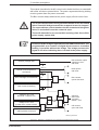
Figure 5.3: Diagram of interfaces for monitoring and diagnostics systems
• DOK-POWER*-KDV*2.3****-ANW1-EN-E1,44 • 06.97
39
6. Guidelines on fault clearance
6.
Troubleshooting guidelines
Lengthy troubleshooting and repair to drive components on the machine are
not acceptable because of the resulting production down-time.
Thanks to their construction, INDRAMAT AC drives enable individual functional
units to be easily and completely replaced without the need for tuning.
This means servicing is limited to fault-location either in the motor, the power
supply module or the drive in the event of a fault. The faulty component can
also simply be exchanged.
6.1. Troubleshooting
Because of the interaction between the NC control unit, the supply and drive
modules, the motor, the mechanical system and position measurement, poor
performance of axis movements can be caused by a fault in the above devices
or incorrect interfacing of individual components. The KDV 2.3 has a
comprehensive diagnostic system for rapid fault location.
Safety guidelines
A fault increases the risk of an accident. Personnel, machinery and drives are
at risk.
Troubleshooting and equipment repair must only be performed by
trained personnel! This personnel must be able to recognize the
dangers of electrical or mechanical equipment, and prevent
dangerous situations!
Guidelines for
protecting personnel
Personnel is not permitted in the danger zone.
Safety measures such as safety screens, covers, and light barriers
must be present.
Access to the E-Stop button must be free and ready.
The following applies when working within the danger zone:
The power to the installation must be switched off and the system
locked so that it cannot be switched back on when working within
the danger zone.
Wait until the DC bus has completely discharged. Depending upon
the DC bus capacitors used, discharge time can take several
minutes. Verify voltage by measuring at X9 (L+/L-).
• DOK-POWER*-KDV*2.3****-ANW1-EN-E1,44 • 06.97
40
6. Guidelines on fault clearance
Danger due to voltage
in conductive parts
There can be dangerous voltages at the following connections:
• At all supply module connections and associated transformers, capacitors
and additional bleeders. In particular, at the power connections (terminal
X9), control voltage input X10, and the blower supply connections X13 and
X14.
• At the drive modules, motors and the plug-in connectors of the motor.
Before working on electrical devices:
Use the mains disconnect to cut power to the entire installation.
Make sure it cannot be switched back on!
Wait for the DC bus to discharge. Depending upon the DC bus
capacitors, discharge can take several minutes. Verify voltage by
measuring it at X9 (L+/L-).
Do not run motor. The motor connections are energized during any
movements of the motor!
Before switching on:
Do not turn on power until the touch-cover shipped with each unit
has been installed!
Notes on protecting
the machine
To avoid damage to the machine, note:
The initial start-up should only be performed by trained personnel.
Make sure that the E-stop and the axis limit switches are operational.
Notes on protecting
the unit
Before switching on:
Make sure the circuitry agrees with the KDV terminal diagram and
electrical schematics for the machine.
Electrostatic loads
Electrostatic loads are hazardous to electronic components. Therefore:
Ground all objects prior to contact with the units.
• DOK-POWER*-KDV*2.3****-ANW1-EN-E1,44 • 06.97
41
6. Guidelines on fault clearance
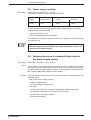
6.2. Diagnostics displays
Please note that the messages are only valid if the +24V- and +/-15V control
voltages are fault free!
The fault messages "bleeder overload" and "ground short" can be cleared by
pressing the reset key on the KDV 2.3 (key S2) or by switching off electronics
power.
OFF
Steady light
LEDs
Bleeder overload
continuous bleeder
operation within
permissible range
red
shutdown due to high bleeder
power, high mains voltage, or
defective drive module
OK
Ground connection
no ground
short
red
shut down due to ground
short in supply module, drive
module, cables or in motor
OK
Auxiliary voltage
green
no mains auxiliary voltage
at terminals X10a/ L1 ... L3
mains auxiliary
voltage
OK
Power OK
green
no power or
power outage
Power
OK
KDV2_Diagnose.fh3
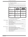
Figure 6.1: The diagnostics displays of the KDV 2.3
6.3. Fault list and remedial actions
LED "bleeder overload" is lit up red
Bleeder overload
Remedy
(Fault message)
Cause 1: Start-stop frequency of the drives too high.
Check load cycle.
Cause 2: Drive energy too high.
Remedy
Check the drive energy.
Cause 3: The bleeder is defective or there is a fault in the KDV2.3
Remedy
Replace the KDV 2.3.
LED "ground short" lit up red
Ground connection
Remedy
(Fault message)
Cause 1: Drive module is defective.
Check drive module and replace, if necessary.
Cause 2: Motor cable is damaged or there is a short in the housing.
Remedy
Check motor power cable and motor.
Cause 3: Fault in the KDV2.3.
Remedy
Replace the KDV 2.3.
• DOK-POWER*-KDV*2.3****-ANW1-EN-E1,44 • 06.97
42
6. Guidelines on fault clearance
Auxiliary voltage
LED "auxiliary voltage" not lit up
(Fault message)
Cause 1: Fuse F3 or F4 is defective
Remedy
Check fuses F3 and F4 and replace, if necessary.
Cause 2: Voltage input interrupted.
Remedy
.
Power O.K.
Remedy
Check the voltage at X10a (230 V AC).
LED "power O.K." does not light up
(Fault message)
Cause 1: Voltage is too low, or a phase on X9 is missing
Check mains input at X9 (3 x 220 V AC)
Cause 2: DC bus voltage less than 200 V DC
Remedy
1. Remove the busbars to the drive and check the DC bus voltage at X9
(L+, L-). Note safety guidelines.
2. Check the DC bus for short circuit.
(Fault message)
Bb1contact does not
close
Remedy
Cause 1: There is a fault in one of the drives.
Check drie diagnostics displays.
Cause 2: There is a fault in the signal voltage of the wire-ribbon connection.
Remedy
1. Check whether the bus cable signal voltage (X1) is properly mounted.
2. Check termination connection of the wire-ribbon connection (X1).
+24 V and/or ±15V
No control voltage
(Fault message)
Remedy
Cause 1: There is no control voltage at X10a or it is faulty
Check the mains fuses in the control cabinet
Cause 2: Maximum signal voltage load exceeded
Remedy
1. Disconnect signal voltage bus cable (X1) to the drive modules and
take new voltage readings.
2. Disconnect signal voltage taps routed in the control cabinet outside
the KDV2.3 or the drive module, and check for short-circuiting.
Cause 3: The fuses F2, F3 or F4 in the KDV 2.3 are defective
Check and replace fuses.
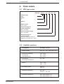
6.4. Fuses
Designation
+24V (output)
auxiliary voltage fuse L1
auxiliary voltage fuse L3
heatsink blower
Symbol
F2
F3
F4
F6
Fine-wire fuse 5 x 20mm
2A/250E medium-blow
10A/250E slow-blow
10A/250E slow-blow
0.63A/250E medium blow
Except for F6, all fuses are mounted to the front of the unit (F6 is on the blower).
Figure 6.2: Fuses
• DOK-POWER*-KDV*2.3****-ANW1-EN-E1,44 • 06.97
43
185 with blower hood
FLAT GASKET
Weight: KDV 2.3
mount access. M1-D
bleeder hood SH-KDV
blower LE 3
Max. total weight
7.
• DOK-POWER*-KDV*2.3****-ANW1-EN-E1,44 • 06.97
approx. 18 kg
approx. 1.7 kg
approx. 1.7 kg
approx. 2.5 kg
approx. 23.9 kg
Stud torque (Nm)
for connecting bolts
7. Dimensional data
Dimensional data
7.1. KDV 2.3 supply module - dimensional data
Figure 7.1: Dimensional data for the KDV 2.3 supply module
44
Safety guard
7. Dimensional data
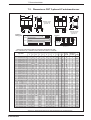
7.2. Dimensions: DST 3-phase AC autotransformer
A
B
A
Type:
B1
G
Standing version
for foot mount
type DST.../S
H
E
F
D
Example:
Rating plate
S
Bj.
DST 2,5/S/380/415/440-220
YNa0
Horizontal version
for wall mount
type DST.../L
Diagram:
1993
220-230V
2,5 kVA
H
E
F
D
K
C
Prim.: 380-400/415/440 V
Sec.:
C1
440V
U4
415V
U3
380V 400V U2
V4
V3
V2
W4
W3
W2
220V 230V U1
V1
W1
40/B
f
1)
b
N
T
a
50/60 Hz
1) Maximum load: DC 24 V/1 A
AC 230 V/1 A
Dimensions and technical data for 3-phase AC autotransformer with
Usec = 220-230 V; Upri = 380-400 V, 415 V, 440 V, 460 V, 500 V, f = 50/60 Hz
Type DST
0.5/ • /380/415/440–220
0.5/ • /380/460/500–220
1.0/ • /380/415/440–220
1.0/ • /380/460/500–220
1.5/ • /380/415/440–220
1.5/ • /380/460/500–220
2.0/ • /380/415/440–220
2.0/ • /380/460/500–220
2.5/ • /380/415/440–220
2.5/ • /380/460/500–220
3.5/ • /380/415/440–220
3.5/ • /380/460/500–220
4.0/ • /380/415/440–220
4.0/ • /380/460/500–220
5.0/ • /380/415/440–220
5.0/ • /380/460/500–220
7.5/ • /380/415/440–220
7.5/ • /380/460/500–220
10/ • /380/415/440–220
10/ • /380/460/500–220
12,5/ • /380/415–220
12,5/ • /440/460–220
12,5/ • /500/525–220
15/ • /380/415–220
15/ • /440/460–220
15/ • /500/525–220
18/ • /380/415–220
18/ • /440/460–220
18/ • /500/525–220
20/ • /380/415–220
20/ • /440/460–220
20/ • /500/525–220
25/ • /380/415–220
25/ • /440/460–220
25/ • /500/525–220
35/ • /380/415–220
35/ • /440/460–220
35/ • /500/525–220
50/ • /380/415–220
50/ • /440/460–220
50/ • /500/525–220
Dimensions in mm
A
B
B1
C
C1
D
E
F
G
H
K
power
loss
in W
150
150
180
180
180
205
205
240
240
240
240
240
240
240
240
300
300
300
300
300
300
335
335
335
360
360
360
360
360
360
360
420
420
420
420
420
420
420
420
580
580
165
165
190
190
190
210
210
260
260
260
260
260
260
260
260
325
325
325
325
325
325
365
365
365
395
395
395
395
395
395
395
450
450
450
450
450
450
450
450
540
540
170
170
205
205
205
235
235
270
270
270
270
270
270
270
270
340
340
340
340
340
340
380
380
380
400
400
400
400
400
400
400
460
75
90
105
115
115
120
120
120
120
140
140
150
150
155
155
140
155
165
180
195
195
195
195
195
190
190
190
205
205
190
205
215
215
215
245
245
245
275
275
255
265
80
95
100
100
110
110
110
135
135
155
155
165
165
170
170
165
180
195
205
220
220
225
225
225
215
215
215
230
230
215
230
210
125
125
125
150
150
150
170
200
200
200
200
200
200
200
200
250
250
250
250
250
250
280
280
280
300
300
300
300
300
300
300
350
350
350
350
350
350
350
350
550
550
70
70
80
80
80
95
95
110
110
110
110
110
110
110
110
140
140
140
140
140
140
160
160
160
170
170
170
170
170
170
170
190
190
190
190
190
190
190
190
270
270
100
100
125
125
125
145
145
170
170
170
170
170
170
170
170
210
210
210
210
210
210
230
230
230
250
250
250
250
250
250
250
280
280
280
280
280
280
280
280
400
400
154
154
185
185
185
209
209
240
240
240
240
240
240
240
240
310
310
310
310
310
310
350
350
350
370
370
370
370
370
370
370
420
6
6
7
7
7
7
7
11
11
11
11
11
11
11
11
11
11
11
11
11
11
11
11
11
11
11
11
11
11
11
11
14
14
14
14
14
14
14
14
18
18
55
70
75
85
85
85
85
90
90
110
110
120
120
125
125
110
125
135
150
165
165
160
160
160
160
160
160
175
175
160
175
165
165
165
195
195
195
225
225
205
215
30
40
45
55
55
75
80
90
95
110
125
130
140
150
160
180
200
230
245
250
260
270
285
290
305
310
330
350
375
380
395
430
450
470
490
540
630
670
720
790
850
max. conn. Wgt.
diameter in kg
in mm2
4
4
6
4
8.5
4
10
4
10
4
11.5
4
11.5
4
18
4
18
4
21
4
21
10
24.5
10
24.5
10
26
10
26
10
30.5
10
36
10
42
10
50
10
53
10
53
10
65
10
65
10
65
16
68
16
68
16
68
16
80
16
80
16
70
16
80
16
92
16
92
35
92
35
122
35
122
35
122
35
152
35
152
70
180
70
195
70
MBDST
Figure 7.2: Dimensional data of the DST threephase AC autotransformer
• DOK-POWER*-KDV*2.3****-ANW1-EN-E1,44 • 06.97
45
7. Dimensional data
7.3. Dimensions: DLT 3-phase AC isolation transformer
A
C1
B1
G1
B
A
Hø
E
F
D
G
C
Hø
E
F
D
Standing version
for foot mount
type DLT.../S
Example: rating plate
Type:
Diagram:
Bj.
DLT 2,5/S/380/415/440-220
1993
Prim.: 380-400/415/440 V
Sec.:
220-230V
S
2,5 kVA
Horizontal version
for wall mount
type DLT.../L
Yyn0
1U1, 1V1, 1W1
1U2, 1V2, 1W2
1U3, 1V3, 1W3
2U1, 2V1, 2W1
T
40/B
f
440 V
415 V
380 V–400 V
220 V–230 V
50/60 Hz
1U1
1U2
1U3
1V1
1V2
1V3
1W1
1W2
1W3
2U1
a
2V1
2W1
2N1
1)
b
1) Maximum load: DC 24 V/1 A; AC 230 V/1 A
Dimensions and technical data for threephase isolation transformer with
Usec = 220-230 V; Upri = 380-400 V, 415 V, 440 V, 460 V, 500 V, f = 50/60 Hz
Dimensions in mm
A
B
B1
C
C1
D
E
F
G
G1
H
power
loss
in W
180
180
205
205
240
240
240
240
300
300
300
300
335
335
360
360
360
360
420
420
580
660
660
190
190
210
210
260
260
260
260
325
325
325
325
365
365
395
395
395
395
450
450
540
590
655
205
205
235
235
270
270
270
270
340
340
340
340
380
380
400
400
400
400
105
105
130
130
140
140
150
150
140
140
165
165
175
175
190
190
205
205
245
275
255
295
305
100
100
120
120
155
155
165
165
165
165
195
195
210
210
215
215
230
230
150
150
170
170
200
200
200
200
250
250
250
250
280
280
300
300
300
300
350
400
––
––
––
80
80
95
95
110
110
110
110
140
140
140
140
160
160
170
170
170
170
190
190
270
270
270
125
125
145
145
170
170
170
170
210
210
210
210
230
230
250
250
250
250
280
280
400
480
480
75
75
95
95
110
110
120
120
110
110
135
135
145
145
160
160
175
175
195
225
205
245
255
185
185
209
209
240
240
240
240
310
310
310
310
350
350
370
370
370
370
7
7
7
7
11
11
11
11
11
11
11
11
11
11
11
11
11
11
16
16
18
18
18
65
70
120
140
155
165
180
195
220
235
240
265
300
350
375
395
500
510
600
800
875
1000
1170
Type DLT
0.5/ • /380/415/440–220
0.5/ • /380/460/500–220
1.0/ • /380/415/440–220
1.0/ • /380/460/500–220
1.5/ • /380/415/440–220
1.5/ • /380/460/500–220
2.0/ • /380/415/440–220
2.0/ • /380/460/500–220
2.5/ • /380/415/440–220
2.5/ • /380/460/500–220
4.0/ • /380/415/440–220
4.0/ • /380/460/500–220
5.0/ • /380/415/440–220
5.0/ • /380/460/500–220
7.5/ • /380/415/440–220
7.5/ • /380/460/500–220
10/ • /380/415/440–220
10/ • /380/460/500–220
15/ • /380–220
20/ • /380–220
25/ • /380–220
35/ • /380–220
50/ • /380–220
max. conn. Wgt.
diameter
in kg
in mm2
4
4
4
4
4
4
4
4
4
4
10
10
10
10
10
10
10
10
16
35
35
70
70
8.5
8.5
13
13
21
21
24.5
24.5
30.5
30.5
42
42
55
55
70
70
85
85
122
152
180
275
320
MBDLT
Figure 7.3: Dimensional data of the DLT threephase AC isolation transformer
• DOK-POWER*-KDV*2.3****-ANW1-EN-E1,44 • 06.97
46
7. Dimensional data
7.4. Dimensional data: CZ 1.02 additional capacitor
102
102
4.4 x 7
M4
12
0
min. 165
Drill holes for
mounting CZ-1.02
44.5
120
MBCZ1.02
Figure 7.4: Dimensional data for the CZ 1.02 additional capacitor
min. clearance
80 mm
7.5. Dimensional data: TCM 1.1 add. capacitor module
18
208
7
air outlet
safety guard
390
355
373
105
L-
L+
L-
L+
9
min. clearance
80 mm
X15
7
60
shown without safety guard
air inlet
Stud torque M (Nm) for
A L-; L+;
from Ms 58 : M5 = 2.5 Nm
X15: L-; L+ = power connections max. 6mm
2
weight: TCM 1.1-04-W0 approx. 6kg
TCM 1.1-08-W0 approx. 7kg
MBTCM
Figure 7.5: Dimensional data for the TCM additional capacitor module
• DOK-POWER*-KDV*2.3****-ANW1-EN-E1,44 • 06.97
47
7. Dimensional data
7.6. Dimensional data: GLD 12/13 smoothing choke
electrical
connection
1
2
C
M6x20
H∅
E
F
B
A
H∅
H∅
oblong hole in
direction "J"
I
J
1.1
2.1
1.2
2.2
1
2
inner schematic diagram
Type
mH/A
B
A
dimensions in mm
C
F H∅
E
I
J
max. conn.
diameter
Gewicht
weight
kg
power
loss
W
100
GLD 12 1.0/100 160 121 285 60
100 7x14 97 121
35mm 2
12
13.5
GLD 13 1.0/50
60 6x10 66
16mm 2
4,6
4.8
122
90
225
--
82
50
MBGLD12/13
Figure 7.6: GLD 12/13 smoothing choke - dimensional data
• DOK-POWER*-KDV*2.3****-ANW1-EN-E1,44 • 06.97
48
7. Dimensional data
7.7. Dynamic brake contactor
Alternating current device:
=
• 220V AC 50/60Hz contactor
LC1-D25008 MA
• 110V AC 50/60Hz contactor
LC1-D25008 F7
• auxiliary block LA1-DN22
• overvoltage limiter
LA4 DA 1U
(RC link)
• bridge for diameter
up to 25 mm2
(Telemecanique,
part no. LA 9-D 2561)
44
=
safety clearance
84
87 (D.1)
87 (D.2)
LA4
10
93
126 (LA1)
56
=
Direct current device
44
=
safety clearance
87 (D.1)
87 (D.2)
LA4
84
• 24V DC contactor
LP1-D25008 BW
• auxiliary block
LA1-DN22
• overvoltage limiter
LA4 DE 1E
(Varistor)
• bridge for diameters
for 25 mm2
(Telemecanique,
part no.: LA 9-D 2561)
10
130
56
163 (2) (LA1)
TVMZwKrschütz
Figure 7.7: Dimensional data for dynamic brake contactor
1
1
49
Ø 34 ± 1,0
7.8. Dynamic brake resistor
215 ± 2
34
5.5 x 7
252 ± 2
Ø 4.4
10
185 ± 2
10
240 ± 1
1 Dynamic brake resistor including mounting
HLZ-300-07Z, 2R2, 300 W
TVMWidZSB
Figure 7.8: Dimensional data for dynamic brake resistor
• DOK-POWER*-KDV*2.3****-ANW1-EN-E1,44 • 06.97
49
8. Order details
8.
Order details
8.1. KDV type codes
Example: KDV 2.3 - 100 - 220 / 300 - 000
Product name
KDV
Series
2
Version
3
Rated current
100 = 100A
Nominal voltage for
power electronics
220 = AC 220V
DC bus nominal voltage
300 = DC 300V
Nominal voltage for
heatsink blower;
AC 115 or 230V, 50 to 60 Hz
(depends on blower type = 000)
Figure 8.1: KDV type keys
8.2. Available versions
Designation
Available version
supply module
KDV 2.3 - 100 - 220 / 300 - 000
electrical connecting
accessories
(see section 8.3)
E10 - KDV
E11 - KDV
E12 - KDV
mechanical
mounting accessories
M1 - KD
blower
LE 3 - 220
LE 3 - 115
smoothing choke
GLD 12
GLD 13
additional capacitors
CZ 1.02
TCM 1.1 - 04 - W0
matching transformer
DST (see section 7.2)
DLT (see section 7.3)
Figure 8.2: Available versions
• DOK-POWER*-KDV*2.3****-ANW1-EN-E1,44 • 06.97
50
8. Order details
8.3. Summary of the electrical connecting accessories
K..
K..
K..
KDV
2.3
KDV
2.3
K..
K..
K..
16 pin
16 pin
E10-KDV
E11-KDV
T..
DDS
K..
K..
KDV
2.3
KDV
2.3
K..
K..
T..
DDS
12 pin
12 pin
E12-KDV
E12-KDV
KDV/Zubehör
Figure 8.3: Summary of electrical connecting accessories
8.4. Order details for mains supply with KDV 2.3
Item
Article
1.0
supply module
KDV 2.3 - 100 - 220 / 300 - 000
1.1
mechanical mounting accessories
M1-KD
1.2
electrical connecting accessories
E...-KDV
1.3
2.0
3.0
4.0
blower unit
LE 3 - ...
bleeder cover
SH-KD
smoothing choke
GLD ..
additonal capacitor
CZ 1.02, TCM 1.1
threephase AC autotransformer
DST. ..././.../.../ - 220
See
Sect. 8.3
Sect. 3.9, 3.14, 8.2
Sect. 2.2, 3.8, 7.6
Sect. 2.2, 3.7, 7.4,
7.5
Sect. 3.2, 7.2
Figure 8.4: Order details of mains supply with KDV 2.3
• DOK-POWER*-KDV*2.3****-ANW1-EN-E1,44 • 06.97
51
9. List of INDRAMAT service reps
9.
List of INDRAMAT service reps
GERMANY
Lohr:
Indramat GmbH
Bgm.-Dr.-Nebel-Str. 2
97816 Lohr am Main
Tel 0 93 52/40-0
Telex 6 89 421
Telefax 0 93 52/40-4885
Chemnitz:
Indramat GmbH
c/o Rexroth Vertriebs- und
Servicegesellschaft mbH
Beckerstraße 31
09120 Chemnitz
Tel 03 71/355-0
Telefax 03 71/355-230
ENGLAND
G.L. Rexroth Ltd.
Indramat Division
4 Esland Place, Love Lane
Cirencester, Glos GL 7 1 YG
Tel 02 85/65 86 71
Telex 43 565
Telefax 02 85/65 49 91
FRANCE
Rexroth - Sigma
Division Indramat
Parc des Barbanniers
4, Place du Village
F - 92 632 Gennevilliers Cedex
Tel 1/47 98 44 66
Telex 616 581
Telefax 1/47 94 69 41
Indramat GmbH
Technisches Büro Ratingen
Harkortstraße 25
Postfach 32 02
40880 Ratingen 1
Tel 0 21 02/44 20 48 /-49
Telefax 0 21 02/41 315
ITALY
Rexroth S.p.A.
Divisione Indramat
Via G. Di Vittorio, 1
I - 20 063 Cernusco S/N. MI
Tel 02/9 23 65 - 270
Telex 331 695
Telefax 02/92 10 80 69
Stuttgart:
Indramat GmbH
Technisches Büro
Liststraße 1/2
71229 Leonberg 1
Tel 0 71 52/25 076/-77
Telefax 0 71 52/25 034
NETHERLANDS
Hydraudyne Hydrauliek B.V.
Kruisbroeksestraat 1a
P.O.Box 32
NL - 5280 AA Boxtel
Tel 04 116/51 951
Telefax 04 116/51 483
AUSTRIA
G.L. Rexroth GmbH
Geschäftsbereich Indramat
Randlstraße 14
A - 4061 Pasching
Tel 07 229/44 01-72
Telefax 07 229/44 01-80
SPAIN
Rexroth S.A.
Centro Industrial Santiga
Obradors s/n
E-08130Santa Perpetua
de Mogoda (Barcelona)
Tel 03/7 18 68 51
Telex 59 181
Telefax 03/718 98 62
Düsseldorf:
DENMARK
BEC Elektronik AS
Zinkvej 6
DK - 8900 Randers
Tel 086/44 78 66
Telefax 086/44 71 60
• DOK-POWER*-KDV*2.3****-ANW1-EN-E1,44 • 06.97
Goimendi S.A.
División Indramat
Jolastokieta (Herrera)
Apartado 11 37
San Sebastian, 20 017
Tel 043/40 01 63
Telex 36 172
Telefax 043/39 93 95
52
9. List of INDRAMAT service reps
SWEDEN
AB Rexroth mecman
Indramat Division
Varuvägen 7
S - 125 81 Stockholm
Tel 08/72 79 200
Telefax 08/99 75 15
REPUBLIC OF SLOVENIA
ISKRA Elektromotorji
Otoki 21
YU - 64 228 Zelezniki
Tel 064/66 441
Telex 34 578
Telefax 064/ 67 150
CANADA
Basic Technologies Corporation
Burlington Division
3426 Mainway Drive
Burlington, Ontario
Canada L7M 1A8
Tel 416/335 - 55 11
Telex 06 18 396
Telefax 416/335-41 84
MEXICO
Motorizacion y Diseño de
Controles
Av. Dr. Gustavo Baz No. 288
Col. Parque Industrial la loma
Apartado Postal No. 318
54 060 Tlalnepantla
Estado de Mexico
Tel 5/39 78 64 4
Telefax 5/39 89 88 8
USA
Rexroth Corporation
Indramat Division
255 Mittel Drive
Wood Dale, Illinois 60 191
Tel 708/8 60 - 10 10
Telex 206 582
Telefax 708/5 30 - 46 31
Rexroth Corporation
Indramat Division
2110 Austin Avenue
Rochester Hills, Michigan 48 309
Tel 313/853 - 82 90
Telefax 313/853 - 82 98
• DOK-POWER*-KDV*2.3****-ANW1-EN-E1,44 • 06.97
ARGENTINA
Mannesmann Rexroth S.A.I.C
Division Indramat
Acassusso 48 41/7
1605 Munro (Buenos Aires)
Argentina
Tel 01/7 56 01 40
01/7 56 02 40
Telex 26 266 rexro ar
Telefax 01/7 56 01 36
BRAZIL
Rexroth Hidráulica Ltda.
Divisão Indramat
Rua Heinrich Passold,130
CP 156
BR - 89. 107-000 Pomerode SC
Tel 04 73/87 03 21
Telex 47 32 88 REXR BR
Telefax 04 73/87 02 51
CHINA
G.L. Rexroth Ltd.
Shanghai Office
Room 206
Shanghai Intern. Trade Centre
2200 Yan Xi Lu
Shanghai 200335
P.R. China
Tel
2755-333
Telefax
2755-666
INDIA
G. L. Rexroth Industries Ltd.
Indramat Division
Plot. 96, Phase III
Peenya Industrial Area
Bangalore - 56 00 58
Tel 80/83 92 10 1
80/83 94 34 5
KOREA
Seo Chang Corporation Ltd.
Room 903, Jeail Building
44 - 35 Yeouido-Dong
Yeongdeungpo-Ku
Seoul, Korea
Tel
02/780 - 82 07 ~9
Telefax 02/784 - 54 08
AUSTRALIA
Australasian Machine Tool
Co. Pty. Ltd.
9 Webber Parade,
East Keilor (Melbourne)
Victoria, 30 33, Australia
Tel 03/336 78 22
Telefax 03/336 17 52
53
10. Index
10. Index
A
Additional capacitance 17
Additional capacitance on the D.C. bus
Additional capacitor 9
Additional components required 9
Applications 7
Autotransformer 13
Auxiliary voltage 43
17
B
Bb1 contact 36
Bb1contact does not open or close
Bleeder overload 42
Bleeder warning contact 37
Blower power supply 17
Busbars 16
BVW contact 37
43
C
Circuit breakers 14
Connecting accessories 51
Connection voltage 13
Continuous bleeder power 9
Continuous D.C. bus power 9
Continuous mechanical output 7
Continuous mechanical power 9
Continuous regenerative power 7
Control circuits 24
Control circuits for a controlled braking of the d
Control circuits with dynamic braking 30
Cooling with a central blower 23
Cooling with a heatsink blower 23
CZ 1.02 9
34
D
D.C. bus 16
D.C. bus dynamic brake 26
D.C. bus dynamic braking 25
D.C. bus peak power 9
D.C. bus short-time power 9
Diagnostics displays 42
Dimensional data 44
Drives - backing up 17
E
E-Stop disengaged 24
Electrical connecting accessories 51
Electronics supply 17
Electrostatic loads 41
Energy capacitor for power failures 17
• DOK-POWER*-KDV*2.3****-ANW1-EN-E1,44 • 06.97
54
10. Index
F
F2 43
F3 43
F4 43
F6 43
Fault current protective device 19
Feedback power too high 37
FI-current limiting type circuit breakers 19
Functional power features of the KDV 2.3 8
Fuse protection for the power connection 14
Fuses 43
G
Gear cutting machines 25
GLD 12 9
GLD 13 9
Grounded threephase mains 15
Guidelines for protecting personnel
40
H
Heat loss 23
Heatsink 23
I
INDRAMAT AC drive system 5
INDRAMAT service reps 52
Installing the KDV 2.3 21
K
KDV 2.3 - data 10
KDV 2.3 power ratings 9
KDV 2.3 supply module design
KDV type codes 50
6
M
Mains connection - power section 13
Mains connection via transformer 13
Mains contactor 14
Maximum feedback energy 9
Maximum permissible fusing 14
Measuring and test purposes 36
Mechanical mounting accessories 51
N
NC bridge 38
Non-periodic overvoltage 15
Notes on protecting the unit 41
O
Order details 50
Output Bb1 36
Output BVW 37
Output NH 37
Output UD 38
• DOK-POWER*-KDV*2.3****-ANW1-EN-E1,44 • 06.97
55
10. Index
P
Peak bleeder power 9
Permissible overvoltage levels 15
Power O.K. 43
Power circuit breaker 14
Power connection 14
Power ratings 9
Power supply in order 38
Protection against accidental contact
16
S
Safety guidelines 40
Selecting the mains contactor 14
Signal voltages 36
Smoothing choke 9
Switching input power on and off 24
T
TCM 1.1 9
Terminal connector 18
Terminal diagram 12
Troubleshooting 40
U
UD contact 38
Ungrounded threephase mains
15
W
Wire-ribbon connection
18
X
X1
18
• DOK-POWER*-KDV*2.3****-ANW1-EN-E1,44 • 06.97
56
Indramat