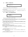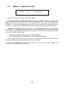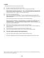
1
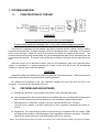
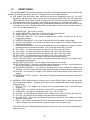
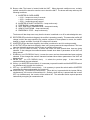
USER’S MANUAL
160KSS360400/50400
2nd Edition
Frequency Converter
Visicomm Industries LLC
911A Milwaukee Ave.
Burlington, WI 53105
CONTENTS
USER’S MANUAL .................................................................................................... 1
1. SYSTEM OVERVIEW........................................................................................ 3
1.1. CONSTRUCTION OF THE UNIT................................................................ 3
1.2. FEATURES AND ADVANTAGES.............................................................. 3
1.3. FRONT PANEL............................................................................................ 5
2. INSTALLATION................................................................................................. 7
2.1. SITE & ENVIRONMENT CONSIDERATIONS........................................... 7
2.2. CABLE SELECTION................................................................................... 9
3. OPERATIONS ..................................................................................................11
3.1. POWER START UP PROCEDURE .........................................................11
3.2. SHUTDOWN PROCEDURE .....................................................................12
4. LCD DISPLAY..................................................................................................13
4.1. MENU 0 - MAIN MENU .............................................................................13
4.2. MENU 1 - SELECT MENU ........................................................................13
4.3. MENU 2 – PARAMETER SET..................................................................14
4.4. MENU 3 – DATE / TIME............................................................................15
4.5. MENU 4 – REAL TIME DATA..................................................................15
4.6. MENU 5 – RECTIFIER DATA...................................................................16
4.7. MENU 6 – DC DATA.................................................................................16
4.8. MENU 7 – OUTPUT DATA.......................................................................16
4.9. MENU 8 – OTHER DATA .........................................................................17
4.10. MENU 9 – STATUS/WARN/FAULT......................................................17
4.11. MENU 10 – HISTORICAL DATA..........................................................18
5. REDUNDANCY ( SYSTEM BACK – UP )......................................................19
6. HELP.................................................................................................................20
©2003, Visicomm Industries. All rights reserved. This book, or any part of it, must not be reproduced in any form
without permission of the copyright owner.
2
1. SYSTEM OVERVIEW
1.1.
CONSTRUCTION OF THE UNIT
WARNING!
Be sure to operate the converter within its rated capacity.
Prevent direct exposure to sunlight, rain, or any other contaminating environment.
The System is composed of an input breaker, input filter & protection network, rectifier, inverter, isolation
transformer and output filter. The basic topology is shown in the diagram above. Operating in the normal AC
mode, energy from the 3 Phase AC source is converted to DC power and supplied to the inverter. The
inverter converts the DC power to three phase AC power and supplies the static switch, which allows the unit
to disconnect from the load. The power is then fed through an isolation transformer and an output filter to the
load.
When the inverter is in an abnormal condition, such as over temperature, short circuit, abnormal output
voltage, or overloaded for a period exceeding the inverter current limit, the inverter will automatically
shutdown, in order to protect itself from damage.
CAUTION!
Hazardous voltage exists inside the Unit (Which includes the connection terminals). Cable connection and
maintenance should be done by professional or qualified personnel.
DC capacitors are employed in this Unit; hazardous voltages still exist even when the Unit is not
energized. Do not touch any part inside of the Unit.
1.2.
FEATURES AND ADVANTAGES
a. Reliable input protection: Circuit breakers are placed in each individual input phase.
b. Input surge protection: MOV (surge protectors) are added at the input, providing sufficient protection to
both the UNIT and the load from any lightning or surge caused by neighboring large loads.
c. EMI suppression: An EMI filter is added to meet the international EMC limits. Therefore,
very low noise is emitted, to prevent interference to other equipment connected to the same AC
source.
d. Ruggedness: The rectifiers employ phase control technology to regulate the DC bus voltage. SCRs
are employed as rectifiers to take advantage of their ruggedness under poor conditions. In addition,
inductors are used at the input to avoid deforming the AC source waveform.
* Option: The solid state transfer switch is supplied as an option for use in serial redundant systems (see page 19 for details)
3
e. High frequency design: The inverter uses high frequency, high efficiency IGBTs, and PWM to convert
the DC power to AC power. The number of components is reduced, resulting in increased reliability,
smaller size and weight, less transportation cost, improved performance, and the elimination of
acoustic noise.
f.
True Galvanic isolation: An isolation transformer is used at the output. This solves the problem of
poor input grounding and will accept a different ground between input and output. Ground the output
to a known earth connection. This avoids the annoying problem of ground leakage current and allows
the output to be tied to any potential provided on site. The AC output is isolated under every mode of
operation. In addition common mode noise from the output isolation transformer is attenuated.
g. Modular design: The power circuit is separated into several modules plugged into slots in the UNIT,
which are easy to remove, permitting quick maintenance and easier trouble shooting (before the DC
bus is energized).
h. Multi-CPU design: Several CPUs are employed in the control circuit, critical functions are designed in
parallel to improve reliability. Therefore, in case of one CPU fails; the other CPUs can assume control
to maintain the output AC.
i.
Operator errors: The UNIT is designed with breaker on/off sensors, power supply sensors, etc. to
prevent user errors from damaging the UNIT.
j.
Wide input range: The UNIT is designed to accept an extra wide input range, so that it can work
comfortably under poor AC source conditions. Also, all the input components used are specially
selected to handle extreme high voltage and high current.
k. Extreme environment: Each component of the UNIT is chosen with a large safety margin to accept
extreme environmental conditions, such as temperature, humidity, altitude, shock, and contamination.
l.
Extended MTBF of fans: Fans will slow down under light load, so that the life expectancy of the fans is
longer than specified.
m. Data log capability: Every abnormal condition will be stored in the converter for further reference. The
data is stored with the date and time ( with a real time clock). When an abnormal condition occurs, the
user can get a full record of what has occurred. The data will not be erased even when all the power is
switched off.
n. Convenient panel design: The LCD display control switch is accessible through the up/down/enter
switch on the front window, which means one can read all the UNIT data without opening the front
door. Of course, the important inverter on/off switch is hidden behind the door (a key is needed to
open it, but you can also switch the inverter on or off from the front window by entering the correct
password in case the key is not at hand or lost), so that it is not easy to accidentally switch the UNIT on
or off.
4
1.3.
FRONT PANEL
The front panel gathers the real time information of the UNIT and displays the data clearly. It also provides
switches for controlling and setting the UNIT. Each part of the panel is explained below:
A. LCD display- Real time status, data, and historical events are displayed on the LCD. The UNIT
parameters, real time clock, inverter, buzzer also can be set through this LCD. The LCD is back lit by
LEDs to provide a clear display, In order to lengthen the LED’s life time, they will be automatically shut
off 3 minutes after no key is activated, and will light up again when one of the keys are pushed.
B. STATUS LEDs- 25 LEDs representing all of the important information of the UNIT will provide current
information to the user. Therefore these LEDs are especially important when abnormal conditions
occur. The 25 status indicators are:
1.
2.
3.
4.
INVERTER ON – the inverter is running.
LOAD CONNECTED – the inverter is connected to the output terminals.
SHORT CIRCUIT – the output is in a short circuit status.
FUSE/OVER TEMP SD – the inverter is shutdown due to either a blown fuse or an over
temperature condition.
5. INVERTER FAILURE SD – the inverter is shutdown due to low inverter output voltage.
6. HIGH DC SHUTDOWN – the inverter is shutdown due to a high DC bus voltage condition when
the inverter is running.
7. OVERLOAD SHUTDOWN – the inverter has shutdown due to overloading the inverter for a period
exceeding the max overload specification. The inverter will restart after 7 seconds.
8. 70% LOAD -- the load connected to the output is over 70% of the UNIT rating.
9. 110% LOAD -- the load connected to the output is over 110% of the UNIT rating.
10. 125% LOAD -- the load connected to the output is over 125% of the UNIT rating.
11. 150% LOAD -- the load connected to the output is over 150% of the UNIT rating.
12. DC LOW – the internal DC bus voltage is less than minimum specifications.
13. DC LOW SHUTDOWN – the inverter has shutdown because the internal DC bus voltage is less
than allowable specifications.
14. RECTIFIER AC FAIL URE -- the AC voltage to the rectifier is out of range.
15. ROTATION ERROR -- the rectifier AC phase rotation sequence is incorrect. Any two phases of
the input AC power must be reversed for the rectifier to function.
16. RECTIFIER SHUTDOWN -- the rectifier is shutdown due to high rectified DC voltage (over
445VDC). The UNIT will automatically restart 30 seconds after the abnormality has been cleared.
17. HIGH DC -- the rectified DC voltage is over 43OVDC and the bus voltage will be limited at this
voltage.
18. EMERGENCY STOP – optional -- the inverter is shutdown because the emergency stop switch
was pushed.
C. WARNING LEDs: When abnormal conditions occur, these LEDs will light to warn the user of the
cause of the faulty condition. Therefore all of these should be extinguished under normal conditions.
These LEDs are:
1. RECT AC FAIL -- AC voltage is out of range, there is a phase rotation error, or the rectifier has
shutdown.
2. FUSE / TEMP -- the inverter fuse is blown or the UNIT is over temperature.
3. OVERLOAD -- the output is overloaded by over 110%, 125% or150%.
4. HIGH DC -- the LED will light as long as the DC voltage to the inverter is over the 430 VDC limit.
5. DC LOW – the internal DC bus voltage is less than minimum specifications.
6. DC LOW STOP -- the inverter has shutdown because the internal DC bus voltage is less than
allowable specifications.
7. FAULT -- the inverter has shutdown due to an abnormal condition such as overload, short circuit,
high DC voltage, fuse, over temperature, bypass breaker, or an emergency stop.
Since these LEDs are located behind the transparent window, the user can see them clearly without
opening the door.
5
D. Buzzer outlet: The buzzer is located inside the UNIT. When abnormal conditions occur, a clearly
audible sound will be issued to warn the user to check the UNIT. The buzzer will beep under any the
following conditions:
1. INVERTER IS OVERLOADED
> 110% -- beeps once every 3 seconds
> 125% -- beeps once every second
> 150% -- beeps twice every second
2. INVERTER IS SHORT CIRCUITED -- beep continuously
3. FUSE BLOWN -- beep continuously
4. HEAT SINK OVER TEMPERATURE -- beep continuously
5. HIGH DC SHUTDOWN -- beep continuously
6. EMERGENCY STOP -- beep continuously
The buzzer will also beep once every time the inverter is switched on or off to acknowledge the user.
E. RECTIFIER LED(on the block diagram): the rectifier is operating normally. This means the rectifier AC
voltage is within the range specified, the rotation sequence of three phases is correct, the rectifier
breaker is closed, and there is no high DC voltage to the inverter.
F. INVERTER LED(on the block diagram): the inverter is switched on and it is running normally.
G. AC OUTPUT LED(on the block diagram): there is AC power present at the output terminal. This is an
important indication to the user that AC power is available at the output.
H. UP key: (on LCD DISPLAY block) It moves the cursor one item upward when items are being
selected. It also changes the number/character forward when data or parameters of the UNIT are
being entered.
I. DOWN key: (on LCD DISPLAY block) It moves the cursor one item downward when items are being
selected. It also changes the number/ character backward when data or parameters of the UNIT are
being entered.
J. ENTER key: (on LCD DISPLAY block)
It selects the previous page. It also enters the
number/character that was selected.
K. ON key: (on INVERTER control block) It is necessary to press this switch and the INVERTER control
key simultaneously to switch the inverter on.
L. OFF key: (on INVERTER control block) It is necessary to press this switch and the INVERTER
control key simultaneously to switch the inverter off.
M. INVERTER key: (on INVERTER control block) When this key is pressed with the inverter ON key
simultaneously, the inverter will be switched on. Similarly, when this key is pressed with the inverter
OFF key simultaneously, the inverter will be switched off. The redundant action required prevents
inadvertently energizing an unwanted mode.
6
2. INSTALLATION
2.1.
SITE & ENVIRONMENT CONSIDERATIONS
The primary function of the UNIT is to provide a safe, clean independent electrical supply to the load which
is :
A) Perfectly regulated in both voltage and frequency
B) Free from any random variations, disturbances or interruptions.
The following precautions and recommendations should be checked in considering the site and
environment of the UNIT:
a. The UNIT should be located in a place with adequate ventilation (refer to the specification of the heat
dissipation of the UNIT). If the UNIT is installed in a closed room, care must be taken to insure the
heat can be evacuated.
b. There are no outlets around the front, rear, left and right side of the UNIT. Empty space is not needed
on any side of the UNIT, but adequate space (at least one meter) should be allowed to open the door
without being obscured by other objects for operation or maintenance. Adequate space (at least one
meter) should be allowed at the top of the UNIT, because heat dissipation is ventilated through the top
openings.
c. Do not put any objects on the top of the UNIT which would reduce ventilation. Do not locate the UNIT
near any heat source, or machinery which produces metallic shavings, dust, or powder, or any facility
which produces corrosive substances or vapor.
d. Do not locate the UNIT below the shower of a fire extinguishing system.
e. The UNIT is capable of continuous normal operation within a temperature range of 0ºC (32ºF) to 40ºC
(104ºF). For optimal performance and reliability it is recommended that the temperature be
maintained below 25ºC and the humidity below 80%.
f. If the UNIT is installed outdoors, avoid direct exposure to sunlight and rain. Avoid direct contact with
sand, dust, or wind.
g. The floor loading capacity should be large enough to accommodate the weight of the UNIT. Four right
angled steel feet or stands are attached to the UNIT. Insert the four 1/2" screws into the floor to secure
the UNIT when it is located in a potential earthquake area or when it is to be used on a moving vehicle.
Dimensions for securing the base are shown below.
h.
7
i.
The walls, ceiling, floor, or anything near the UNIT should be constructed of non-combustible
materials.
j. A portable fire extinguisher should be accessible.
k. Avoid accumulating litter or trash of any sort in or around the UNIT. The floor area surrounding the
UNIT should be kept clean so that metallic filings and powder are not sucked into the unit causing a
short circuit and possible damage to the system.
l. Personnel who operate or maintain the UNIT should be proficient in normal and emergency
operational procedures. New personnel should be trained and qualified to operate the equipment.
m. Although the UNIT has passed international EMC tests, it is not recommended to install the UNIT near
any equipment that is susceptible to electro-magnetic interference.
n. If long cabling is required, it is preferable to place the UNIT nearer to the source than to the load.
Carefully take off all the packaging material of the converter, and then locate the converter on a site which
has been selected in accordance with all the points in section 3.1.
The converter has passed the production testing and QC, checking all the electrical and mechanical
characteristics in detail prior to shipment from the factory. Therefore the converter should be in proper
condition upon receipt. Once received, check the mechanical structure and see if any physical damage was
made during transportation.
Check if all the accessories / options (matched with your purchase order) have been attached.
-
DOOR KEY
THIS INSTRUCTION MANUAL
BATTERY FUSE (FOR OPTIONAL BATTERY CABINET ONLY)
SPARE SCREWS FOR COVER PLATE
SPARE SCREWS FOR CONNECTION TERMINALS etc.
Lastly, check if the specifications of the converter are identical to the specifications you ordered. The key
items in the specifications you must check are:
-
RATED POWER OF THE CONVERTER
INPUT VOLTAGE & FREQUENCY
OUTPUT VOLTAGE & FREQUENCY
NUMBER OF INPUT PHASES (1 ~ OR 3 ~)
NUMBER OF OUTPUT PHASES (1 ~ OR 3 ~)
BATTERY VOLTAGE OR CELL NUMBER
Also check the necessary documentation that is attached:
-
GUARANTEE CARD
8
2.2.
CABLE SELECTION
The unit should be installed by an electrician qualified to interpret and implement the national and
local electrical codes.
The following table lists the operating voltage and the maximum input current for all the KVA ratings of the
converters. The right two columns list the standard output voltages and their respective maximum output
currents for all the different models. Since the input and output voltages are often different, it is necessary to
refer first to the KVA rating and then select the appropriate current for both the input and output.
The utility input circuit breaker servicing this unit should be selected to be at least as large as the input
breaker on the unit and coordinated so that the unit’s input breaker trips first. The internal electronic current
limit is designed to shut the unit down in the event of an overload and before the units input circuit breaker
trips. Therefore under normal circumstances the units input breaker will rarely trip.
If the overload is
removed the unit will automatically come back on after a few seconds. Note that the final input cable size will
need to accommodate the rated output of the utility input circuit breaker.
This data is for reference, final decisions should be made in accordance with the national and local
electrical codes. Inadequate cable size or over sized breakers will incur risk of fire or damage of insulation.
9
2.3.
TABLE OF MAXIMUM CURRENTS FOR
BOTH THE INPUT AND OUTPUT
KVA RATING
10
20
30
40
50
60
80
100
120
160
200
300
400
I/P VOLTAGE
120/208
220/380
277/480
120/208
220/380
277/480
120/208
220/380
277/480
120/208
220/380
277/480
120/208
220/380
277/480
120/208
220/380
277/480
120/208
220/380
277/480
120/208
220/380
277/480
120/208
220/380
277/480
120/208
220/380
277/480
120/208
220/380
277/480
120/208
220/380
277/480
120/208
220/380
277/480
I/P CURRENT
O/P VOLTAGE
O/P CURRENT
38.5
21
16.7
79
43
34
119
65
51.6
158
86
68
198
108
86
238
130
103
315
172
134
396
215
172
449
245
195
590
322
256
739
404
320
1109
604
480
1478
808
640
120/208
220/380
277/480
120/208
220/380
277/480
120/208
220/380
277/480
120/208
220/380
277/480
120/208
220/380
277/480
120/208
220/380
277/480
120/208
220/380
277/480
120/208
220/380
277/480
120/208
220/380
277/480
120/208
220/380
277/480
120/208
220/380
277/480
120/208
220/380
277/480
120/208
220/380
277/480
33
18
14.3
66
36
28.6
99.9
54.5
43.3
133.8
73
58
166.8
91
72.3
199.8
109
86.6
267.7
146
116
333.7
182
144.5
399.7
218
173.1
535.3
292
231.9
667.3
364
289.1
999.2
545
432.9
1332.8
727
577.4
10
3. OPERATIONS
After all cables have been connected, the converter is ready to operate once the power source is available
at the input terminal. Before you turn on any switch or breaker, check the following points listed below:
a.
b.
c.
d.
e.
See if the input voltage is within tolerance for the converter’s rated input voltage.
See it the input frequency conforms to the converter’s rated input frequency.
Check if all loads at the output are switched off.
All breakers are opened – turned off.
The battery disconnector, if you have that option, is opened – turned off.
3.1.
POWER START UP PROCEDURE
To start the converter, from complete shutoff to normal operation, follow the steps below
to turn it on.
a. Close the reserve breaker -- The LCD display and various LED’s on the front panel will
light up.
b. Close the rectifier breaker -- Check the ROTATION ERROR led on the front panel. If
this Led is ON the input phase rotation sequence is incorrect and the rectifier will not
function. In this case reverse any two of the input phases. If the phase rotation
sequence is correct the internal DC voltage will slowly rise (15-30 sec.) until the
designated voltage is reached. At this point the DC LOW light on the front panel will
go OFF and the internal DC supply is ready to supply power to the inverter.
c. Push the INVERTER ON switch and the CONTROL switch simultaneously -- The
inverter will start working and the inverter output will be established within 4 sec.
Then the load will automatically transfer to the inverter within 3 sec. At this point the
converter is operating normally. In addition the fans will now rotate.
d. Close the Output breaker
e. Check that all the LED’s on the front panel block diagram are lighted. All the
WARNING LED’s on the right hand side should be off. Two LEDs: INVERTER ON
and LOAD CONNECTED on the left hand side should be lit. If the load is over 70%,
the 70% LOAD LED will also light.
11
3.2.
SHUTDOWN PROCEDURE
If you want to shutdown the converter completely (no power at the output or inside),
please follow the steps below.
a. Open the Output breaker.
WARNING – If there is no load or the load has been
disconnected externally prior to opening the Output breaker, the output terminals will
maintain a DC voltage due to filter capacitors on the output terminals. Before contacting
these terminals they should be discharged.
Discharge each output terminal to the
Output Neutral terminal before contacting these terminals.
b. Push the INVERTER OFF switch and the CONTROL switch simultaneously -- This will
remove power from the load and turn off the inverter.
c. Open the rectifier breaker -- Opening the rectifier breaker will remove the power source
from the internal DC bus and the internal DC supply will slowly drop. Wait 5 min for the
Internal DC capacitors to discharge.
d. Open the reserve breaker -- Before opening the reserve breaker, always make sure
there is no critical load connected to the output.
e. The converter is completely shut off. None of the LEDs or the LCD display should be lit.
Open the utility breaker feeding power to the converter. There is now no power on the
inside or outside of the converter. If you plan to access the inside of the unit, make sure
the internal capacitor bank is fully discharged.
12
4. LCD DISPLAY
The LCD screen can display much more information than LED’s. In order to make the display sharp and
readable, the LCD is back-lit. To prolong the life time of the back-lighting, the CPU will turn off the back light
after 3 minutes if no keys are pressed. Of course, the back light will stay lit if the UP, DOWN or ENTER keys
are pressed.
The first page of the LCD is the MAIN MENU, which is the first screen that is displayed once the system
power is enabled (i.e. this is the default screen).
4.1.
MENU 0 - MAIN MENU
VISICOMM USA
1-800-421-4430
P/N: 17B4D
S/N: 03099014
ID: 00
160 KVA
I: 277/480 V / 60 HZ
O: 230 / 400 V / 50HZ
2003 / 10 / 07
WED 02:14 PM
1st Line: Displays the greeting text set by the factory.
2nd Line : This contains the part number (P/N), serial number (S/N), and the identification number (ID).
3rd Line : This line will display the KVA rating, input rating and output rating of the converter.
4th Line: This line will display the date (year/month/day) and the day of the week and the time of day. This is
used in the historical menu to time stamp any unusual events.
WARNING:
Never change the part number yourself, because important system parameters such as the
power rating will be changed!
The serial number is set by the factory for the convenience of maintenance personnel who may need to
take down the serial number of the converter in case of service. The identification number is set only when an
external module is connected to more than one converter. Each one must have a unique number to identify
itself, and should be set by technical personnel after installation. The YEAR/MONTH/DATE, DAY OF THE
WEEK, HOUR: MINUTE and AM (PM) from the real time clock inside the converter are displayed in the fourth
row for user’s reference and stamping the date and time in the historical data.
Pressing either the UP, DOWN or ENTER key will cause the LCD will to change to another screen, the
MENU 1 or SELECT MENU.
4.2.
MENU 1 - SELECT MENU
<SELECT MENU>
STATUS/WARN/FAULT
REAL TIME DATA
HISTORICAL DATA
? PARAMETER SET
EXIT
The Select Menu will display a cursor (? ) for the user to select what type of data they want to view or they
may change the settings of the converter. The cursor (? ) can be moved upward with the UP (?) key, and
downward with the DOWN (?) key. The selection is confirmed by pressing the ENTER (<+ ) key. If the item
‘PARAMETER SET’ is selected, the LCD will display a screen which will ask the user to key in the password.
See MENU 2 – PARAMETER SET menu below.
This menu will allow the user to turn the Inverter
ON/OFF, turn the warning beeper ON/OFF, set the DATE/TIME clock for the UNIT, and
allow the user to Boost Charge the optional battery system.
The STATUS/WARN/FAULT display will show the current status of the unit, and any warnings or faults
13
that could be present. See MENU 9 – STATUS/WARN/FAULT below.
The HISTORICAL DATA display will list any system faults such as input power failure or other problems
within the UNIT. See MENU 10 – HISTORICAL DATA below.
4.3.
MENU 2 – PARAMETER SET
<PARAMETER SETTING>
INVERTER = ON
BUZZER = ON
BOOST CHARGE
? DATE / TIME
EXIT
This menu is selected from MENU 1, the SELECT MENU.
to enter this menu.
However, the system will require a password
The password can be entered upward or downward by the UP (?) or the DOWN (?) keys, and can be
confirmed by the ENTER (<+ ) key for each digit. The password is a 4 digit number. The selection will
continue if the correct password is entered or will go back to MENU 0, the MAIN MENU, if an incorrect
password is entered after 3 trials. The password for entering the <PARAMETER SET> menu is factory preset
to 1-2-3-4.
If ‘EXIT’ is selected (blinking instead of pointed by cursor), the display will return to the MENU 0 – MAIN
MENU.
The first item that can be set is the INVERTER ON/OFF control. When it is selected ‘INVERTER ON/OFF’
will be displayed. The ‘ON’ will blink if the inverter status is on, and the ‘OFF’ will blink if the inverter status is
off. The status can be changed by the UP(?) or DOWN(?) key, and is confirmed by the ENTER(<+) key.
Then ‘INVERTER = ON’ will be displayed if ‘ON’ is selected or ‘INVERTER = OFF’ will be displayed if ‘OFF’ is
selected. This enables the converter to switch the inverter on or off via the front panel display controls without
opening the front door, a feature that can be useful if the front door is locked and the key is not readily
available.
The second item that can be set is the BUZZER ON/OFF control. When it is selected ‘BUZZER ON/OFF’
will be displayed. The ‘ON’ will blink if the buzzer status is on, and the ‘OFF’ will blink if the buzzer status is off.
The status can be changed by the UP(?) or DOWN(?) key, and is confirmed by the ENTER(<+) key. Then
‘BUZZER = ON’ will be displayed if ‘ON’ is selected or ‘BUZZER = OFF’ will be displayed if ‘OFF’ is selected.
The third item that can be set is the BOOST CHARGE. When it is selected the BOOST CHARGE
SETTING MENU will be displayed. Note that this is an optional feature which is only applicable when a
battery back up is employed.
The fourth item that can be set is the DATE/TIME.
will be displayed. This is explained below.
14
When it is selected the DATE/TIME SETTING MENU
4.4.
MENU 3 – DATE / TIME
<DATE/TIME SETTING>
YEAR = 2003
HOUR(24H) = 14
MONTH = 09
MINUTE = 45
DAY = 25
DAY OF THE WEEK = THU
EXIT
This menu is selected from MENU 2, the PARAMETER SETTING menu. The user can change the
YEAR/MONTH/DAY/HOUR/MINUTE/DAY OF THE WEEK of the real time clock through this menu. When
this menu is selected, the current value in the real time clock will be displayed. The cursor (? ) can be moved
upward by the UP (?) key, and can be moved downward by the DOWN (?) key, to the item you want to change.
The selection is confirmed by pressing the ENTER (<+ ) key. The values to be entered are numbers, (except
the DAY OF THE WEEK, MON, TUE, etc., are provided for your selection). The values that can be entered are
restricted to certain values, according to which item is being set.
The value can be increased upward by the UP (?) key, and can be decreased downward by the DOWN (?)
key. The value will flash if it is being set. You can continue to push the UP (?) or the DOWN (?) key until the
expected value is displayed. Again, the selection is confirmed by pressing the ENTER (<+ ) key. Then the
values in the real time clock are changed according to the values you enter and the real time will continue to
run based on these values.
If ‘EXIT’ is selected (blinking instead of pointed by cursor), the screen will go back to MENU 2 - the
PARAMETER SETTING menu.
4.5.
MENU 4 – REAL TIME DATA
<REAL TIME DATA>
? RECTIFIER DATA
DC DATA
OUTPUT DATA
OTHER DATA
EXIT
This menu is selected from MENU 1, the SELECT MENU.
The first item that can be selected is the RECTIFIER DATA display. This will display the
AC input voltage and frequency to the rectifier assembly. This is shown in the RECTIFIER DATA menu below.
The second item that can be selected is the DC DATA display. This will display the internal DC bus
voltage and the Charge Current for the optional battery backup system. This is shown in the DC DATA menu
below.
The third item that can be selected is the OUTPUT DATA display. This will display AC output voltage,
frequency, and the percentage of maximum output current to the load. This is shown in the OUTPUT DATA
menu below.
The fourth item that can be selected is the OTHER DATA display. Currently this will display the internal
heat sink temperature in degrees centigrade. This is shown in the OTHER DATA menu below.
If ‘EXIT’ is selected (blinking instead of pointed by cursor), the screen will go back to MENU 1 - the
SELECT MENU menu.
15
4.6.
MENU 5 – RECTIFIER DATA
<RECTIFIER DATA>
RECTIFIER FREQUENCY = 60 HZ
A–B = 238 Vac B–C = 238 Vac C–A = 240 Vac
This menu is selected from MENU 4, the REAL TIME DATA menu.
This menu will display the AC power input frequency and the input voltage.
illustrated this is the phase to phase voltage of each phase.
The UP(?) or DOWN(?) keys have no function in this menu.
REAL TIME DATA menu when ENTER(<+ ) is pressed.
4.7.
For the three phase input
The display will return to MENU 4 – the
MENU 6 – DC DATA
<DC DATA>
DC VOLTAGE = 388 Vdc
CHARGE CURRENT = 1 A
This menu is selected from MENU 4, the REAL TIME DATA menu.
This menu will display the internal rectified DC bus voltage. This DC voltage should normally be 320 Vdc
to 430 Vdc and is controlled by the rectifier assembly. If for any reason the voltage is not in this range the
UNIT will issue a warning or will shutdown. Shutdown will occur should the voltage drop below 295 Vdc.
The Charge Current is the battery charge current and is only applicable when the optional battery backup
system is employed. If the converter is in back-up mode, the data displayed is the discharge current of the
battery, and the display will change to ‘DISCHARGE CURRENT =’.
The UP(?) or DOWN(?) keys have no function in this menu.
REAL TIME DATA menu when ENTER(<+ ) is pressed.
4.8.
The display will return to MENU 4 – the
MENU 7 – OUTPUT DATA
<OUTPUT DATA>
OUTPUT FREQUENCY = 50 HZ
LOAD: A=16% B=17% C=17%
A-N = 120 Vac B-N = 120 Vac C-N = 120 Vac
This menu is selected from MENU 4, the REAL TIME DATA menu.
This menu will display the frequency, output voltage, and output current. The displayed load is the
percentage of maximum specified output load current. In the example above this is a percentage of each of
the three phases. The display illustrated shows a three phase “wye” output in which case each phase to
neutral voltage is displayed. The UP(?) or DOWN(?) keys have no function in this menu. The display will
return to MENU 4 – the REAL TIME DATA menu when ENTER(<+ ) is pressed.
16
4.9.
MENU 8 – OTHER DATA
<OTHER DATA>
TEMPERATURE = 26°c
This menu is selected from MENU 4, the REAL TIME DATA menu.
This menu will display the temperature in degrees centigrade of the internal heat sink for the IGBT’s
(switching regulators).
The UP(?) or DOWN(?) keys have no function in this menu.
REAL TIME DATA menu when ENTER(<+ ) is pressed.
4.10.
The display will return to MENU 4 – the
MENU 9 – STATUS/WARN/FAULT
<STATUS>
RECTIFIER ON
INVERTER ON
LOAD ON INVERTER
<WARNING>
This menu is selected from MENU 1, the SELECT MENU.
The left hand column of this menu shows the real time status of the rectifier, inverter and load switch
states. The right hand column shows the warning or fault condition, if any. Under normal conditions, the
display should be exactly the same as the figure shown above.
If minor abnormal conditions occur, they will be displayed under the title <WARNING>. However
<WARNING> conditions will be overridden by <FAULT> messages if more serious abnormal conditions occur,
and the title < WARNING> will change to <FAULT >.
Listed below are all the warning conditions that can be displayed (they are arranged in order of priority,
starting with the highest priority):
1st Line: RECT AC FAIL / RECTIFIER PHASE ERROR
2nd Line: 170% OVERLOAD / 150% OVERLOAD /125% OVERLOAD / 110% OVERLOAD
3rd Line: BATTERY LOW STOP / BATTERY LOW / BATTERY BAD / BATTERY GND FAULT / BATTERY
TESTING
Listed below are all the fault conditions that can be displayed:
1st Line: HIGH DC SHUTDOWN
2nd Line: SHORT CIRCUIT! / FUSE/OVERHEAT / OVERLOAD SHUTDOWN / EMERGENCY STOP /
INVERTER ABNORMAL
The UP (?) or DOWN (?) key has no function in this menu. The screen will go back to MENU 1- the
SELECT menu, when ENTER (<+ ) is pressed.
17
4.11.
MENU 10 – HISTORICAL DATA
<DATE/TIME/EVENTS>
2003/09/10
14:14
RUN:00YR00MO
FUSE/OVERHEAT
This menu is selected from MENU 1, the SELECT MENU.
The records are stored in EEPROM when abnormal events occur and are displayed in this menu. The
record display begins with the date and time stamp of each abnormal event. The user or maintenance
personnel can trace back these events up to 77 records (which can be increased to 154 records with 2
EEPROMs). These records will not be erased by cutting off the power supply or by complete shutdown of the
converter, i.e. they will be kept in EEPROM forever unless over written by the 78th (or the 155th) record.
3 records can be displayed at a time on the screen. The records displayed are the 3 most recent records
in the EEPROM. The displayed records will move one record upward when the UP (?) key is pressed, and
move one record downward when the DOWN (?) key is pressed. The abnormal conditions that caused the
events to be recorded, are listed below:
1. HIGH DC SHUTDOWN / SHORT CIRCUIT / FUSE/OVERHEAT
2. OVERLOAD SHUTDOWN / EMERGENCY STOP / INVERTER ABNORMAL
On the top right corner of the screen, the converter run time is displayed in year/month for the reference of
the user or maintenance personnel to estimate the time for maintenance.
The UP (?) or DOWN (?) key has no function in this menu.
SELECT menu, when ENTER (<+ ) is pressed.
18
The screen will go back to MENU 1- the
5. REDUNDANCY ( SYSTEM BACK – UP )
Redundancy can be roughly divided in two types: serial (hot standby) redundancy and parallel (active)
redundancy.
A serially redundant system consists of two converters, with the output of the second converter connected
to the reserve input of the first converter. The load is connected to the output of the first converter.
Both converters are normally running. The load is being supplied entirely by the first converter and is
protected by the first converter. If the first converter has battery support the load will still be supplied by the
first converter and its battery in the event of a power failure and the second converter is still in standby mode.
If the first converter should fail the load is automatically transferred from the output of the first converter to
its reserve input and then the second converter will supply the load thru the reserve input of the first converter.
The load is now being supplied entirely by the second converter and is now protected against overload etc. by
the second converter. If the second converter has battery support the load will still be supplied by the second
converter and its battery in the event of a power failure.
If both of converters are running normally, the first converter takes up the entire load and the second
supplies no load. In this case the second converter has a longer MTBF than that of the first. However these
can be interchanged after a period of time, and their MTBF multiply to a larger MTBF.
This is the type of redundancy employed most frequently. If the mains should fail, this topology can make
full use of the battery. This system provides double the protection and double the back-up time. It should be
noted that the total power output is not doubled.
19
6. HELP
Some practical situations are discussed in this section.
Q:
A:
AC input is normal, but the rectifier does not operate?
Check if the rectifier breaker has been closed. Solution: Close the rectifier breaker.
Check if the phase sequence of the AC input is correct. The LCD will display error message ‘RECT
PHASE ERROR’ in the STATUS/WARN menu. The ROTATION ERROR led on left hand side of the
front panel will light as well. Solution: Correct the input connection.
Q:
A:
The inverter can not be switched on?
Check if the DC bus has been established. The ‘DC LOW’ leds on the front panel should be off.
Solution: Allow enough time for the rectifier or battery to establish the DC bus as indicated by the ‘DC
LOW’ leds going off.
Check that the reserve breaker is closed. Solution: Close the reserve breaker.
Check if the output is overloaded. The LCD will display error message ‘XXX% OVERLOAD’ in the
STATUS/WARN menu. The ‘XXX% OVERLOAD’ led on left hand side of the front panel and
‘OVERLOAD’ led on the right hand side of the panel will light up as well. Solution: Decrease the load
to under the converter’s rated power.
Q:
A:
The converter system with battery support shuts down under mains failure?
Check if the battery fuse holder/disconnector has not been closed. Solution: Close the battery fuse
holder/disconnector.
Q:
A:
The converter does not display front panel leds and the LCD display is off?
Check that the reserve breaker has been closed. Solution: Close the reserve breaker.
Q:
A:
The ‘FAULT’ led lights up and the buzzer beeps continuously?
Check if the output is overloaded. Solution: Decrease the load.
Check if the output is short circuited. Solution: Clear the short at the output.
***
If the above suggestions cannot solve your problem, please contact the your local service center.
©2003, Visicomm Industries. All rights reserved. This book, or any part of it, must not be reproduced in any form
without permission of the copyright owner.
20