1
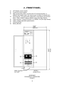
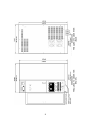
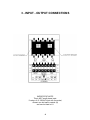
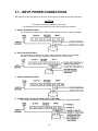
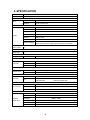
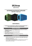
USER’S MANUAL
8KSS60400
3rd Edition
Frequency Converter
Visicomm Industries LLC
911A Milwaukee Ave.
Burlington, WI 53105
1. INTRODUCTION
The conversion of electrical power is an essential requirement for export testing or
operation of equipment brought to the U.S. from abroad. The KSS series Frequency
Converter is designed to meet these needs as it supplies reliable, pure and stable
power at an affordable price.
This Converter is designed with the following unique features
l Double Conversion IGBT module, Single control board design, eliminates
adjustment, and minimizes maintenance.
l LCD display for unit status, user friendly design
l Special overload capacity design, 150% overload for 30 sec.
l Built-in isolation transformer to ensure total isolation between the input and
output.
l Special airflow control to avoid dust accumulation. Suitable for rough operating
environments.
l Front door access for ease of installation and servicing.
l Compact size, light weight
1
2 - FRONT PANEL
11.
12.
13.
14.
15.
16.
17.
18.
LCD display selector switch
Frequency selector switch
Main input breaker (SW1): Controls the AC commercial power, in
addition this breaker trips if the output power is subject to a dead short.
Input terminal: The input power leads will be connected to the terminal
block. Either 120VAC range or 220VAC range (See Spec Sheet).
Output terminal: 2 ranges 120VAC L-N, 240VAC L-N (See Spec Sheet).
Output voltage adjustment potentiometer
Ground terminal
Battery Breaker
8KSS60400
FREQUENCY CONVERTER
(FRONT)
2
3
8KSS60400
FREQUENCY CONVERTER
(FRONT)
8KSS60400
FREQUENCY CONVERTER
(BACK)
3 - INPUT - OUTPUT CONNECTIONS
IMPORTATNT NOTE!
This is NOT a split phase input.
If using a U.S. 220VAC Input with no neutral,
connect one hot lead to neutral (N)
and one hot lead to L2.
4
Input Power Connections and Grounding
S ystem Ground Connection:
The Earth Ground should be provided by the utility. This is normally the “GREEN” wire
provided by the utility which at some point is routed to a secure earth ground such as a water
pipe. This wire should be connected to the screw post marked GND on the Converter (See
photo for location).
Note that there are no internal electrical connections to this wire with the exception of a
small high frequency bypass capacitor for RF suppression. Therefore, the function of the Earth
Ground is simply to maintain the case of the Converter at ground potential. Visicomm Industries
(LLC) does not recommend any other connection to the Earth Ground wire which may introduce
significant amounts of current and thereby defeat the intended purpose of this wire which is the
safety of the operating personnel. In particular, do not connect this wire to the system neutral
wire at any point.
Output Connection:
The Power OUTPUT Connections are provided by three barrier terminal posts labeled N,
L1, and L2. These three terminals constitute the three terminals of an internal auto-transformer
were L1 is the “center tap”. This is fed by the output winding of a switching transformer. Since
the only other internal connections are a resonating capacitor, the cooling fans, and sensing
circuits( to maintain an output sine wave ), these output terminals are electrically isolated from
any other circuits including the system neutral.
The Converter is shipped with these OUTPUT connections electrically isolated. If a digital
voltmeter is connected between any one of these OUTPUT terminals and the Earth Ground, a
significant voltage reading will be obtained. This voltage is due to a small leakage current and is
not considered a problem since only 1 or 2 ma is involved.
Output Isolation:
Many applications require an isolated output, primarily for safety reasons, when supplying
power to a device under test especially if there will be other monitoring equipment connected to
the device. Other applications can take advantage of the low leakage current of the Converter
(about 1 or 2 ma). This can be useful in systems where the individual leakage currents of the
components might exceed the allowed leakage current of a ground fault interrupter.
Other applications require that the output have a connection to the utility NEUTRAL.
Normally this would be OUTPUT terminal N (The exception would be a two phase output where
L1 would be the connection to the system NEUTRAL). The Converter is supplied with a short
jumper wire. If the system NEUTRAL is used to power the INPUT terminals and it is required that
the OUTPUT be connected to NEUTRAL this jumper can be employed to make this connection.
If the INPUT is supplied by two phase AC or by two phases of a three phase system (in
other words, if you have only two incoming power wires), this NEUTRAL would not be present
and an external wire from the desired OUTPUT terminal to the system NEUTRAL would be
required. See INPUT CONNECTION DIAGRAM on next page.
N
L1
L2
Basic diagram of output stage
5
3.1 - INPUT POWER CONNECTIONS
The frequency of the input power can be 50 or 60 Hz, and is not related to the output frequency
CAUTION:
The Input is Electrically Isolated from the output.
It is necessary to connect the input using one of the following four methods.
A. SINGLE PHASE 220V INPUT
This connection is usually used in 50Hz countries where a neutral is normally available.
B. SPLIT PHASE 220V INPUT
This connection is usually used in 60Hz countries where a 220V line is not normally
available, and where the input amperage makes using 120V inconvenient.
C. SINGLE PHASE 120V INPUT
D. THREE PHASE 120/208 VAC USING LINE TO LINE INPUT
To be used if the 120V line to neutral connection is limited by the amperage available.
6
3.2 - OUTPUT POWER CONNECTIONS
The frequency of the output power is 50 or 60 Hz, and is not related to the input frequency
CAUTION:
The output is "floating" and is electrically isolated from the input.
It is necessary to connect the output using one of the following three methods.
Note that these output voltages are widely adjustable using the voltage adjust rheostat.
A. SINGLE PHASE 120V OUTPUT
B. SINGLE PHASE 220V OUTPUT
C. SPLIT PHASE 220V OUTPUT
7
4. SPECIFICATION
Model
8KSS60400
Capacity
8KVA/6.4KW
Input
Voltage
120 or 220VAC -15%/+20%
Frequency
50 Hz or 60 Hz ± 5%
Voltage
120 or 220VAC ± 20 % (adjustable)
Frequency
400Hz (50 Hz or 60 Hz available)
Voltage Regulation ± 1 %
Output
Frequency Stability
Transient
Response
Waveform
± 0.0004% with xtal oscillator
± 3% (100% Load variation) No load to full load with full recovery
within 5 cycles
Sinewave THD < 3% at 0 -100% linear load
Overload Capacity 110% continuous, 110-150% load 30 seconds, over 150% causes
unit to shut down. Auto restart upon removal of the overload
Power Factor
0.8
Crest Ratio
3:1
Efficiency
AC to AC
> 85%
Overload
150% 30sec cut off (Current Limited)
Protection
Audible Alarm
Indicators
Environment
Short Circuit
Unit will cut-off and must be manually restarted
EMI Filter
10-100KHz at 40dB, 100KHz-100MHz at 70dB
Overload
Sounds continuously
Fault
Sounds continuously
LCD
Converter status, I/P & O/P voltage, I/P & O/P frequency
Line: Green LED
Inverter: Green LED
Fault: Red LED
Overload: Yellow LED
LED
Operation Temp.
-10ºC to 50 ºC; 14ºF to 122ºF
Relative Humidity
20-90% non-condensing
Audible Noise
Less than 58dB (at 1 meter)
Input
Output
Physical
Dimensions
Terminal Block
Terminal Block (Worldwide outlets available)
Net Weight
366lbs / 165kg
Width
18.90” / 48cm
Depth
13.39” / 34cm
Height
30.77” / 84cm
8