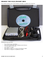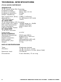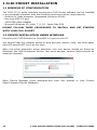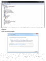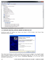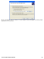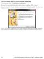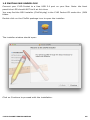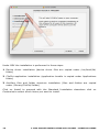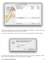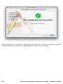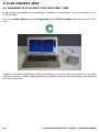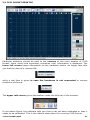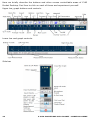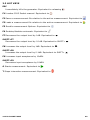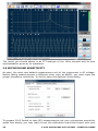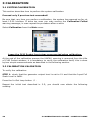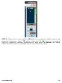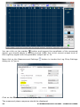
1
ELECTRICAL & ACOUSTICAL TESTS
CLIO Software
Release 1.1
Version Pocket
Survival Guide
AUDIOMATICA
1
© Copyright 1991–2015 by
AUDIOMATICA SRL
VIA MANFREDI 12
50136 FLORENCE, ITALY
PHONE: +39-055-6599036
FAX: +39-055-6503772
www.audiomatica.com
[email protected]
All Rights Reserved
Edition 1.10, 2015/03
IBM is a registered trademark of International Business Machines Corporation.
Windows is a registered trademark of Microsoft Corporation.
Apple, Mac, OSX are registered trademarks of Apple Inc.
CONTENTS
INSIDE THE CLIO POCKET BOX..........................................5
TECHNICAL SPECIFICATIONS............................................6
CP-01 AUDIO INTERFACE............................................................................6
MIC-02 MICROPHONE.................................................................................6
CLIO POCKET SOFTWARE REL.1.1 UNDER X-RAYS.............7
LOG CHIRP ANALYSIS.................................................................................7
FFT AND RTA ANALYSIS..............................................................................7
SIGNAL GENERATOR AND OUTPUT CONTROLS...............................................8
INPUT METER AND CONTROLS.....................................................................8
WATERFALL...............................................................................................8
THIELE & SMALL PARAMETERS.....................................................................8
SYSTEM....................................................................................................9
1 CLIO POCKET INSTALLATION.......................................10
1.1
1.2
1.3
1.4
1.5
1.6
MINIMUM PC CONFIGURATION.............................................................10
DRIVER INSTALLATION UNDER WINDOWS.............................................10
DRIVER INSTALLATION UNDER WINDOWS XP.........................................12
SOFTWARE INSTALLATION UNDER WINDOWS........................................14
INSTALLING UNDER OSX.....................................................................15
HOW TO UNINSTALL CLIO POCKET UNDER OSX......................................19
2 CLIO POCKET MAP........................................................20
2.1
2.2
2.3
2.4
2.5
2.6
RUNNING CLIO POCKET FOR THE FIRST TIME.........................................20
CLIO POCKET DESKTOP.......................................................................21
HOT KEYS..........................................................................................23
THE GRAPH DISPLAY...........................................................................24
INITIAL TEST MEASUREMENT...............................................................27
MICROPHONE SENSITIVITY..................................................................28
3 CALIBRATION...............................................................30
3.1 SYSTEM CALIBRATION.........................................................................30
3.2 CALIBRATION VALIDATION...................................................................30
3.3 TROUBLESHOOTING CLIO INSTALLATION...............................................33
4 ENJOY CLIO POCKET.....................................................34
4.1
4.2
4.3
4.4
4.5
IMPEDANCE MEASUREMENTS AND T&S PARAMETERS..............................34
CONNECTING THE MICROPHONE..........................................................40
ANECHOIC FREQUENCY RESPONSE OF A LOUDSPEAKER SYSTEM..............42
WATERFALL........................................................................................47
IN-ROOM MEASUREMENTS...................................................................48
5 REFERENCES.................................................................55
INSIDE THE CLIO POCKET BOX
You should receive your CLIO Pocket housed in a plastic box like this:
Inside the box you find:
–
–
–
–
–
–
The CP-01 Audio Interface
The CLIO Pocket CD with software and drivers
The Microphone MIC-02
One USB 2.0 cable
One RCA to RCA 2.7m long microphone cable
One RCA to alligators impedance cable
INSIDE THE CLIO POCKET BOX
5
TECHNICAL SPECIFICATIONS
CP-01 AUDIO INTERFACE
GENERATOR
24 Bit sigma-delta D/A Converter
Frequency range:
1Hz-45kHz
Frequency accuracy:
better than 0.01%
Frequency resolution:
0.01Hz
Output impedance:
150Ω
Max output level (Sine): 13dBu (3.46Vrms)
Attenuation:
0.1 dB steps to full mute
THD+Noise(Sine):
.008%
AC ANALYZER
24 bit sigma-delta A/D Converter
Input range (full scale): +40dBV down to -40dBV
Max input acceptance:
+40dBV (283Vpp)
Input impedance:
64kΩ (5.6kΩ mic)
Phantom power supply: 8.2V
DC ANALYZER
12 bit A/D Converter
Input range:
± 6.5V
MISCELLANEOUS
Sampling frequencies:
96kHz and 48kHz.
Connections:
analog RCA in and out
Digital connection:
USB 2.0 port
Power supply:
USB powered (480 mA)
Dimensions (cm):
9(w)x12(d)x2.5(h)
Weight:
0.3 kg
MIC-02 MICROPHONE
Type:
Accuracy:
Maximum level:
Dimensions:
6
Condenser electret
±1 dB, 20 Hz to 10 kHz
±2 dB, 10 kHz to 20 kHz (direct field)
130 dB SPL
8 mm diameter, 12 cm long
TECHNICAL SPECIFICATIONS CLIO POCKET - SURVIVAL GUIDE
CLIO POCKET SOFTWARE REL.1.1 UNDER X-RAYS
LOG CHIRP ANALYSIS
-
Amplitude, frequency and time calibrated response.
Chirp length: 16384, 65536 points
Impulse length range: 1.36s down to 170ms
Frequency range: 10Hz to 45kHz
Frequency response units: dBV, dBu, dBRel, dBSPL
Impedance response units: Ohm
Frequency and time simultaneous display, analysis and post-processing
Frequency smoothing (1/48 to 1 fraction of octave)
Phase response (Normal, Minimum and Excess)
Auto-Capture Delay with manual interactive fine-tuning
Group Delay response (Normal, Minimum and Excess)
Time Impulse response
Step response
Schroeder impulse decay
Energy Time Curve
Quasi-Anechoic acoustic response with start and stop time window selection
Time window: Rectangular or Auto-Half Hann tuned to impulse max
Continuous loop measurements for easy interactive tuning of systems
AutoStore to Overlay function to track up to 10 curves on screen
Math processing: Add file
Math processing: Divide by file
Math processing: Merge High and Low frequency response
Math processing: dB Shift
Math processing: MIB (Microphone In the Box) technique
Save Impulse time data to wav file
Export ASCII data to file or clipboard to be imported in simulation software
Export Graphic data to file or clipboard for easy reporting
FFT AND RTA ANALYSIS
-
Narrow-band FFT analyzer
FFT size: 4096, 16384, 65536 points
Acquisition range: 1.36s down to 42ms
Frequency range: 10Hz to 45kHz
Measurement units: dBV, dBu, dBRel, dBSPL
Time window: Rectangular, Hanning, Hamming, Bartlett, FlatTop
Average: linear to target count or continuously exponential
Average count: 1 to 9999
Continue average function to add next linear count
Max or Min hold function
Frequency and time simultaneous display and analysis
Frequency smoothing (1/48 to 1 fraction of octave)
Real-Time fraction-of-octave analyzer (RTA)
RTA bands: 1/3 or 1/6 octave
Event trigger with programmable delay and threshold
OneShot event trigger function
Save acquired time data to wav file
Export ASCII data to file or clipboard
Export Graphic data to file or clipboard for easy reporting
CLIO POCKET SOFTWARE REL.1.1 UNDER X-RAYS
7
SIGNAL GENERATOR AND OUTPUT CONTROLS
-
Dedicated Generator Panel with on-the-fly controls
Plays standard wav files
Highly optimized waveform calculator
Waveform: Sinusoid, FFT-bin optimized, bursted and tapered
Waveform: Two Sinusoids with relative amplitudes
Waveform: CEA burst with cycles control, FFT-bin optimized and tapered
Waveform: White noise
Waveform: Chirp, Lin or Log, up to 256k size and start and stop frequencies
Waveform: Pink noise, FFT matched, pseudorandom, low crest factor
Waveform: All Tones, FFT matched, low crest factor
Dedicated main window surface with output controls
All controls speeded up by hot keys
Direct 3-digit input of output level
Button control for 1dB or 0.1dB steps
INPUT METER AND CONTROLS
-
Free-running Voltmeter and Sound Level Meter with bar graph
Measurement units: V, dBV, dBSPL
Voltage reading range: from few μV to 100V RMS
Interactive L-C-R meter
Measured components: Resistors, Capacitors, Inductors
Direct measurement of microphone sensitivity
Direct measurement of reference voltage
Dedicated main window surface with input controls
All controls speeded up by hot keys
Button control input sensitivity in 10dB steps
Input-Output Loop button
Input polarity inversion
Input gain autorange
Microphone power supply
WATERFALL
-
Decay analysis with 3-D gesture-controlled swiveling graph
Multiple windows allowed for easy comparison
Analyzes Log Chirp Impulse response or FFT time data
Classical Cumulative Spectral Decay for loudspeakers characterization
Frequency smoothing (1/48 to 1 fraction of octave)
Reference operation
Fully configurable frequency, time and amplitude axis
Number of spectra: 15 to 120
THIELE & SMALL PARAMETERS
-
8
Interactive Control Panel to simplify operation
Free Air parameters
Added Mass or Known Volume methods for full parameters estimation
Direct measurement of ReDC.
Multiple windows allowed for easy comparison
CLIO POCKET SOFTWARE REL.1.1 UNDER X-RAYS CLIO POCKET - SURVIVAL GUIDE
SYSTEM
-
Software operates native under Windows or OSX
Touch and gesture compliant software design
Hardware relies on dedicated USB driver
Ultra stable, glitch-free, streaming operation
Self-calibration with comparison to Audiomatica Labs calibration conditions
Stored calibration parameters trace international standards
Assistance warning in case of any component run out of spec with time
Security warning in case of any unauthorized parameter change
CLIO POCKET SOFTWARE REL.1.1 UNDER X-RAYS
9
1 CLIO POCKET INSTALLATION
1.1 MINIMUM PC CONFIGURATION
The CLIO CP-01 audio interface running the CLIO Pocket software can be installed
in any personal computer with the following minimum system requirements:
– Pentium IV class processor (suggested minimum 2GHz)
– One free USB 2.0 port
– 1024x786 video adapter
– Microsoft Windows XP, Vista, 7, 8, 8.1, Apple Mac OSX
PLEASE FOLLOW THESE PROCEDURES TO INSTALL AND GET STARTED
WITH YOUR CLIO POCKET!
1.2 DRIVER INSTALLATION UNDER WINDOWS
Connect your CLIO Pocket to a free USB 2.0 port on your PC.
You should hear the classical sound of plug and play device; note: the front panel
blue LED should NOT be lit at this time.
After the initial automatic driver detection only one device should be found by
Windows, the USB Composite Device; two more devices, named ClioPkt should be
installed manually.
Open Device Manager (type devmgmt.msc from Run prompt or click Control
Panel>System>Device Manager):
10
1 CLIO POCKET INSTALLATION CLIO POCKET - SURVIVAL GUIDE
Right-Click on each ClioPkt device under Other Devices and choose Update Driver
Software.
At the successive prompt:
Browse your computer and point to the folder inside the installation CD where the
proper drivers are located (usually \Windows\Driver\Vista_7_8).
At the end of installation you will get the ClioPkt Control and ClioPkt Stream
entries within Device Manager:
1 CLIO POCKET INSTALLATION
11
Your driver installation was successful!
1.3 DRIVER INSTALLATION UNDER WINDOWS XP
Installing under XP differs as, when you plug in CLIO Pocket, the Found New
Hardware Wizard starts
The wizard will direct you while installing the two drivers needed. You should Install
from a specific location and point to the driver folder for XP on the CD (usually
\Windows\Driver\XP) and then answer Continue Anyway to the prompt about
Windows Logo testing.
12
1 CLIO POCKET INSTALLATION CLIO POCKET - SURVIVAL GUIDE
At the end please refer to above 2.2 and inspect Device Manager to verify proper
installation of the drivers.
1 CLIO POCKET INSTALLATION
13
1.4 SOFTWARE INSTALLATION UNDER WINDOWS
This paragraph deals with software installation.
Be sure to have administrative rights when installing CLIO Pocket.
Launch the CLIO Pocket installer running the ClioPktSetup.exe file from the
installation CD:
At the end of the wizard the CLIO Pocket software should be installed smoothly;
take note of the installation folder (usually C:\Program Files\Audiomatica\ClioPkt).
14
1 CLIO POCKET INSTALLATION CLIO POCKET - SURVIVAL GUIDE
1.5 INSTALLING UNDER OSX
Connect your CLIO Pocket to a free USB 2.0 port on your Mac. Note: the front
panel blue LED should NOT be lit at this time.
You may find the OSX installer (ClioPkt.pkg) in the CLIO Pocket CD under the /OSX
folder.
Double click on the ClioPkt package icon to open the installer:
The installer window should open:
Click on Continue to proceed with the installation.
1 CLIO POCKET INSTALLATION
15
Under OSX the installation is performed in three steps:
1 Device driver installation (device driver files are copied under /usr/local/lib/
folder)
2 ClioPkt application installation (application bundle is copied under Applications
folder)
3 Ancillary files and folder structure installation (files and folders are copied
under /Library/ClioPkt/ folder)
Click on Install to proceed with the Standard Installation elsewhere click on
Customize to select which items you want to install.
16
1 CLIO POCKET INSTALLATION CLIO POCKET - SURVIVAL GUIDE
Click on Standard Install to go back to the Standard Installation, or select the items
you want to install and click on the Install button.
In order to install the Device Drivers the system root password should be typed:
At this point the installer copies the folders and files to the local installation media.
At the end of the installation you should get this message:
1 CLIO POCKET INSTALLATION
17
The installation is successful, depending on your OSX version you should find the
ClioPkt application under user /Applications/ folder and Launchpad.
18
1 CLIO POCKET INSTALLATION CLIO POCKET - SURVIVAL GUIDE
1.6 HOW TO UNINSTALL CLIO POCKET UNDER OSX
At the end of the installation you should have the following items added to your
system:
1 Device drivers library:
$ ls /usr/local/lib | grep libftd
libftd2xx.1.2.2.dylib
libftd2xx.dylib
2 ClioPkt application bundle:
$ ls /Applications/ | grep ClioPkt
ClioPkt.app
3 Directory structure
$ ls /Library/ClioPkt/
Cal Help Signal
Tables
Temp
In order to completely uninstall CLIO Pocket from your Mac, and cleanup the files
copied by the installer, you should delete all the files above.
1 CLIO POCKET INSTALLATION
19
2 CLIO POCKET MAP
2.1 RUNNING CLIO POCKET FOR THE FIRST TIME
If you have completed the preceding installation procedures, you are ready to run
CLIO Pocket!
From the Start Menu choose Programs, then CLIO Pocket and click on the CLIO
icon.
Upon a successful installation the front panel blue led should now light up, you may
hear the internal relays clicking and the program should start smoothly and present
the main desktop.
20
2 CLIO POCKET MAP CLIO POCKET - SURVIVAL GUIDE
2.2 CLIO POCKET DESKTOP
Particular attention should be paid to the corners of the main window of CLIO
Pocket; there useful and important, sometime vital, information is displayed. The
lower left corner keeps information on the hardware status. An happy face tells
you that the device is running OK:
while a sad face is given in case the hardware is not connected or various
problems are found:
The upper left corner gives information inside the title bar of the window:
In the above figure, the software tells you that it has not been calibrated or that it
needs to be calibrated. This is the default state when first running CLIO Pocket.
2 CLIO POCKET MAP
21
Here we briefly describe the buttons and other mouse controllable areas of CLIO
Pocket Desktop. Feel free to click on each of these and experiment yourself.
Upper bar, graph buttons and controls.
Lower bar and graph controls.
Side bar.
22
2 CLIO POCKET MAP CLIO POCKET - SURVIVAL GUIDE
2.3 HOT KEYS
ESC
Immediately kills the generator. Equivalent to releasing
F1 Invokes CLIO Pocket manual. Equivalent to
F2 Saves a measurement file relative to the active measurement. Equivalent to
F3 Loads a measurement file relative to the active measurement. Equivalent to
F5 Recalls measurement Options. Equivalent to
F6 Enables/disables autoscale. Equivalent to
F7 Decreases the output level by 1dB. Equivalent to
SHIFT+F7
Decreases the output level by 0.1dB. Equivalent to SHIFT+
F8 Increases the output level by 1dB. Equivalent to
SHIFT+F8
Increases the output level by 0.1dB. Equivalent to SHIFT+
F9 Increases input acceptance by 10dBV.
SHIFT+F9
Decreases input acceptance by 10dBV.
G Starts measurement. Equivalent to
T Stops interactive measurement. Equivalent to
2 CLIO POCKET MAP
23
2.4 THE GRAPH DISPLAY
The figure explains the main objects found in a Frequency response measurement
display. Inside the graph you find the main curve which reflects an executed (or
loaded from disk) measurement; up to nine overlays curves which are stored by
the user and can be controlled interactively, the two markers which are activated
by clicking on the respective buttons. Above the graph itself we find several buttons
and checkboxes which divide into three main categories: Y scales controls, main
curve, zoom and overlays management.
Each overlay can be displayed, hidden or selected with the relative
checkbox.
Marker A reads the main curve; marker B has a twofold operation: it reads
the selected overlay, if present, otherwise it reads the main curve again.
Beside and below the graph we find the Y Scales, the Frequency (or Time) Scale
and Marker Indicators. The Y scale is of the same color of the main curve selected.
24
2 CLIO POCKET MAP CLIO POCKET - SURVIVAL GUIDE
It is possible to directly input the Y scale values; to activate the input
boxes simply click on the scale extremes.
HOW TO ZOOM
1) Click on the Zoom+
button.
2) Position the mouse and PRESS the left mouse button at the beginning of your
selection and keep the mouse button pressed. Don't just click otherwise you get
a warning message!
3) With the mouse button pressed move the mouse until the second selection point.
4) Now release the left mouse button.
Be careful: you must have the button pressed from point 2) to point 4)!
It is also possible to zoom by direct input of the Frequency extremes of the
scale; to activate the input boxes simply click on the scale extremes.
2 CLIO POCKET MAP
25
THE CHIRP TIME DOMAIN DISPLAY
Figure 6.2
In this case there is only one overlay. It is also possible to select a portion of the
main curve by means of three particular buttons. The selected portion of the main
curve is identified by a start and stop point and is drawn in a different color from
the unselected portion.
Defines the start point of the selection. Before clicking with the button
activate Marker A and position cursor to the desired point.
Defines the stop point of the selection. Before clicking with the button
activate Marker A and position cursor to the desired point.
Returns the curve to a completely unselected state.
26
2 CLIO POCKET MAP CLIO POCKET - SURVIVAL GUIDE
2.5 INITIAL TEST MEASUREMENT
Let's now execute our first test measurement: to play and capture a 1kHz sinusoid.
The In-Out Loop
button should be down, click on it if not; in this way CLIO
connects output with input with an internal relay. This connection is very important
as it lets you capture and analyze a signal generated by CLIO without the need for
an external connecting cable.
Then click on the generator icon
to play a 1kHz sinusoid, it's the default signal.
The input meter should react as in Figure and display the level in Volts of the signal
at the input.
If everything is OK you should obtain a reading of circa 1V, variable between a
minimum of 0.95V and a maximum of 1.05V, which is the mean output level of a
sinusoidal signal when the system is not calibrated.
Now press the FFT
the Go
Button.
2 CLIO POCKET MAP
button, the Frequency and Time Graphs
button and finally
27
The result you should obtain is an FFT analysis of the 1kHz sinusoid and its time
representation given by its waveform.
2.6 MICROPHONE SENSITIVITY
As seen, the main and default measurement unit of the instrument is AC voltage.
Before taking measurements in different units, such as dBSPL, you must input the
proper transducer sensitivity. To do this open the Options>Units dialog
To prepare CLIO Pocket to take SPL measurements set your microphone sensitivity
inside this dialog; you may read it from the calibration chart that comes with your
28
2 CLIO POCKET MAP CLIO POCKET - SURVIVAL GUIDE
microphone:
In the case of figure input 13.4 mV/Pa in the Pressure>Sensitivity edit box.
29
3 CALIBRATION
3.1 SYSTEM CALIBRATION
This section describes how to perform the system calibration.
Proceed only if previous test succeeded!
Be sure that, any time you perform a calibration, the system has warmed up for, at
least 15-20 minutes. If done too soon you may receive the Calibration Failed
warning message; in case repeat the procedure after a while.
Select Calibration from the Main menu
Leave the CLIO Pocket front plugs unconnected when calibrating.
At the end of the calibration process the UNCAL! warning is removed from the title
of CLIO Pocket window; it is mandatory to verify the calibration itself; this is done
by two simple measurements as described in the following section.
3.2 CALIBRATION VALIDATION
To verify the calibration:
STEP 1: check that the generator output level is set to 1V and that the Input Full
Scale Level is 0dBV.
Press the In-Out Loop button
.
Repeat the initial test described in 3.5; you should now obtain the following
reading:
30
3 CALIBRATION CLIO POCKET - SURVIVAL GUIDE
STEP 2: Then click on the LogChirp
button to invoke the LogChirp panel and
press the Frequency Graph
button. Press the Go
button to execute a
LogChirp Frequency response measurement; after about 1 second you should
obtain the desired result, a straight line as in the following Figure.
3 CALIBRATION
31
You can click on the marker
button and inspect the amplitude of the measured
signal: you should obtain a reading around 0dBV, this is the correct output level of
the LogChirp signal with the generator output set to 1V.
Now click on the Measurement Settings
dialog as in Figure.
button to invoke the Log Chirp Settings
Click on the Phase checkbox and press OK.
The measured phase response should be displayed.
32
3 CALIBRATION CLIO POCKET - SURVIVAL GUIDE
The correct readings should be around zero degrees.
3.3 TROUBLESHOOTING CLIO INSTALLATION
To receive assistance please contact Audiomatica at [email protected] or
connect to our website www.audiomatica.com.
33
4 ENJOY CLIO POCKET
4.1 IMPEDANCE MEASUREMENTS AND T&S PARAMETERS
Once the Calibration has been verified it's time to start performing some
measurements. Loudspeaker Impedance can be measured with CLIO Pocket out of
the box. Connect the RCA to Alligator Impedance Cable to the CLIO output and to
the Loudspeaker terminals (as in the Picture). Verify that the loop button
is still
down. Select the LogChirp
Analysis. Basically everything should, for now, be left
unchanged since the measure done to validate the calibration. Performing a new
measure with the loudspeaker connected something like the following should
appear on the screen:
34
4 ENJOY CLIO POCKET CLIO POCKET - SURVIVAL GUIDE
Actually this is not an Impedance Curve, but a Frequency Response showing the
log scaled voltage division of CLIO’s output impedance with the loudspeaker’s input
impedance. Open the LogChirp Settings
and change both Size to 65536 and
Units to Ohm.
With the latter settings, perform the measure again. We finally get an impedance
measurement:
4 ENJOY CLIO POCKET
35
Obviously yours should be different with a similar shape. You will have to adjust the
Y scale either manually or with the AutoScale Button. Why we changed Units to
Ohm should be obvious. Increasing the Size of the Measurement and relative FFT
brings enhanced low Frequency resolution. This is advisable measuring woofers and
midranges. The default output level of 1.000V is fine in most cases, but can be
increased with high impedance devices. Input level should be set to the maximum
gain before overload occurs to. This maximize SN ratio. For 1.000V output 0dBV is
a good starting point.
Before dealing with how to calculate T&S Parameters, which is a post-processing of
Impedance Measurements, let’s be sure that we have everything set by measuring
Capacitors and Inductors. Just disconnect the Loudspeaker and replace it with
either of the two.
36
4 ENJOY CLIO POCKET CLIO POCKET - SURVIVAL GUIDE
Click on the Units label within the Level Meter and select the correct measurement
units for the component under test (Resistance, Capacitance, or Inductance). Then
press the
arrow that starts all measurements and you should see a real time
measurement.
We end this chapter by covering T&S Parameters, because these are calculated by
post-processing impedance measurements. One obtained in free air, which means
with the Loudspeaker as is, the second acting a perturbation on the moving part
that can be either an Added Mass or a Known Volume. In the first case the
Resonance Frequency will decrease, in the second increase. Our example will be
with Added Mass as it is usually easier to achieve.
4 ENJOY CLIO POCKET
37
While the whole procedure can be carried with Impedance present in memory but
not saved, we strongly suggest that you carry out the two measurements and save
them with meaningful names. It is a good idea to include the amount of Mass (or
Volume) used in the name of the second file while “FreeAir” is a good choice for the
first.
With the Free Air measurement in memory open the CLIO Pocket Option Dialog
and choose T&S Parameters Tab. Check that Free Air Radio Button is selected and
fill the required data.
Note that if the Loudspeaker is connected the DC resistance Re can be directly
measured by CLIO clicking on the Measure button. Also notice that Diameter and
Area are either/or options. You may set one and the other will be set accordingly
once the field is exited. Confirm and Close pressing OK. Now Clicking on the T&S
Parameters Button
the Free Air parameters should appear.
38
4 ENJOY CLIO POCKET CLIO POCKET - SURVIVAL GUIDE
To get the complete set of Parameters load the Added Mass Impedance file and,
again recall the CLIO Pocket Options, T&S Tab
By selecting the Added mass Radio Button the Added Mass value input will appear.
Input the weight of the used mass and confirm with the OK Button. By clicking the
T&S Parameters Button
again, the complete set of T&S Parameters should
appear.
4 ENJOY CLIO POCKET
39
4.2 CONNECTING THE MICROPHONE
If, up to testing T&S Parameters, everything has worked as described, is now time
to connect the microphone. Leave the loudspeaker connected as for impedance.
Using the RCA to RCA 2.7m long microphone cable connect the MIC02 to the CLIO
Input. Check you have set the correct Sensitivity as written in 2.3. Put the
microphone in the Speaker Nearfield as shown in the picture above. Turn the Mic
Power Supply
on. Release the In-Out Loop
button. This disconnects the CLIO
input from its output, connecting the input only to the RCA socket and therefore to
the microphone. Click on the LogChirp
button and then the Measurement
Settings
button to invoke the Log Chirp Settings dialog:
Choose dBSPL as unit, set everything else as above confirm with the OK button and
40
4 ENJOY CLIO POCKET CLIO POCKET - SURVIVAL GUIDE
perform the measurement
.
Repeat measuring and adjusting Input Gain until the maximum before overload. In
the figure above we have it set at -40dBV (10mV) full scale which is the highest
possible Input Gain. Depending on the speaker this might change. You can also
safely increase or reduce the Output level to keep the response within 80 to 90
dBSPL. You should obtain a Pressure Frequency Response even if, for several
reasons, it is not the real one of the speaker. Try to get confident with this
measurement, which is absolutely safe for the speaker because CLIO does not have
a high power output. Even with Output set at its maximum 3.4V, it is unlikely that
even a micro speaker would fail, because it is connected via a 150 ohm resistor. If
you are confident so far, it is time to try to perform an anechoic Frequency
Response of a loudspeaker system.
4 ENJOY CLIO POCKET
41
4.3 ANECHOIC FREQUENCY RESPONSE OF A LOUDSPEAKER SYSTEM
Up to now what was in the CLIO box was sufficient. To proceed now you have to
connect your own audio power amplifier via an an RCA cable. The amplifier should
possess a flat Frequency Response and a low output impedance. Check that the
CLIO generator is turned OFF
and that the amplifier is turned OFF. Connect
CLIO's Output to the amplifier input and the amplifier's output to the speaker you
are measuring. Refer both to the above picture and the schematic below
Note that the polarity of the cable from the amp to the loudspeaker is inverted. This
42
4 ENJOY CLIO POCKET CLIO POCKET - SURVIVAL GUIDE
compensates for the fact that the supplied MIC02 inverting the signal as do most
measuring microphones. However, it is possible to correct this issue in a more
elegant way using the Input Polarity button
. In our example we will measure a
relatively small two way loudspeaker. For a physical small speaker it is advisable to
put the microphone at 50-70cm from the speaker, thus obtaining a longer
reflection-free measurement than when testing at 1m. The greater the distance
between both the speaker and the mic. from any reflecting surfaces, the better.
In the above figure you see the common practice of placing absorbing material to
attenuate the first reflection. However be advised that, as long as this affects only
high frequencies, it has the disadvantage of masking the exact arrival time by
slowing the rise of the reflected impulse. Therefore, it is ideally better to delay the
arrival time of the first reflection than to absorb it, if possible.
Once the set-up is ready, if there is a volume control turn it to the lowest position
and switch the amplifier on. Check that the microphone power supply is on, set
CLIO Input gain to -30dBV, and verify that the bar-graph on the right of the Level
Meter responses to a hand clap. Set the latter to dBSPL.
4 ENJOY CLIO POCKET
43
If there is a volume control on the amplifier it should have been already set
counter-clockwise (to minimum). Therefore leave the CLIO Output level at its
default 1.000V. In absence of a volume control on the amplifier set CLIO Output
level at 0.01V or below. Open the Generator Control Panel and generate Pink Noise
by clicking on Pink and then on Play. You can ignore the Size for now.
Either with the amplifier's volume control, or with the CLIO output level control
arrows, increase the level(you should hear a sound like a waterfall, which is Pink
Noise). Adjust the output to read around 80dBSPL on the Level Meter. Turn the
Generator Off. Click on the LogChirp
button to invoke the LogChirp panel and
press the Frequency & Time Graph
button so that you have Frequency and Time
Domains visible at the same time. Press the Go
button to execute a LogChirp
Frequency Response measurement with exactly the same settings shown for the
Nearfield measurement.
44
4 ENJOY CLIO POCKET CLIO POCKET - SURVIVAL GUIDE
Here we have Frequency and Impulse responses. The Frequency Response is not
Anechoic. In the Time Domain, Zoom both X and Y axes to fit your situation of
impulse and reflections. Eventually temporarily select the Time Domain only Button
for a bigger and more detailed Impulse. Activate Marker A, verify that the
distance of the peak of the Impulse is what you expect, locate the first reflection,
put the Marker A immediately before and click on the Set Stop Window Button
.
If you left both Domains visible, as suggested, you should see immediately how the
Frequency Response changes. As a last refinement open the LogChirp Settings
and in the Time Processing settings change the Window from Rectangular to Auto
Half Hann.
Below is what we obtained. The Frequency Response is much smoother then before
with less bass extension and a less steep high-pass behavior. The average level is in
the 87dBSPL range, higher than what was measured using Pink noise. This is
expected and correct.
4 ENJOY CLIO POCKET
45
In the status bar, information regarding the measurements and its processing are
reported. With the stop window set at 8.75ms and an impulse arrival time of 1.8ms
the low frequency reliability limit is around 150 Hz. We did not set the Start
Window, because it does not change the Frequency Response. If you are interested
in anechoic responses it is unlikely you need a bigger measurement size than 16k,
but for room acoustics 64k is advisable.
46
4 ENJOY CLIO POCKET CLIO POCKET - SURVIVAL GUIDE
4.4 WATERFALL
The 3D decay of the anechoic response, known as the Cumulative Spectral Decay, is
achieved by the Waterfall post processing.
Open the measurement settings dialog and choose Waterfall. Input: Start
Frequency 200Hz, Smoothing 1/3 Octave, Range 30dB.
Click of the Waterfall button.
Click with the mouse over it and enjoy.
4 ENJOY CLIO POCKET
47
4.5 IN-ROOM MEASUREMENTS
We are going to execute two acoustical FFT measurements that characterize the
quality of perceived sound and the room environment surrounding us.
Both measurements are done at a listening position; the first tells us about the
overall tonal balance and is done with third-octave RTA analysis; the second aims to
give us an idea of room behavior with respect to decay of sound.
Unlike Log Chirp measurements, FFT and RTA are interactive; the user can chose
either to generate a particular stimulus signal or simply analyze what is present at
the mic input. When possible, when using a stimulus, it is advisable to use CLIO's
internally generated signals because they lead to more precise and powerful
analyses. Here we describe two examples exploiting both methods.
Let's prepare for our RTA measurement with an example. As seen in the photo
above, we have placed a Rogers-like loudspeaker in our listening room for
measuring.
To measure a loudspeaker in a similar situation, place the microphone at a listening
position and connect the mic. cable to the CLIO input. Set the Mic Power Supply to
ON
; In-Out Loop
to open (i.e. button released); Input Sensitivity to -20dBV.
Set CLIO's Output Level starting low, say 0.1V, and the CLIO generator to OFF
.
With the power amplifier turned OFF, and the volume control to minimum, connect
the CLIO output to the power amplifier line input and then you may turn the power
amplifier on.
Press the FFT
button, then enter FFT Options and set Size to 65536, Units to
dBSPL and check the RTA box.
48
4 ENJOY CLIO POCKET CLIO POCKET - SURVIVAL GUIDE
Close the dialog, set the Meter units to dBSPL, press the FFT Go button to start the
analysis. Because the generator is still OFF you should be analyzing only the
fluctuating noise of the room.
Now prepare the generator; click on the Generator Control Panel button aside the
Generator ON/OFF one
4 ENJOY CLIO POCKET
49
a new window should pop up, from here it is possible to generate the required
signal for our analysis; choose Pink and select 64k Size from the drop down.
Note that we left Averaging equal to 1 in the FFT settings because we are using a
pseudo-random pink-noise stimulus of same length as the FFT size. Press Play; you
should hear Pink Noise out of the speaker and view the RTA Frequency Response on
screen, with the average level of the signal shown in the Meter box. Now carefully
increase the Output until you reach a realistic listening level, for these speakers say
87 dBSPL. You may then capture your Frequency Response by pressing STOP.
Switch Generator OFF (or simply press ESC).
50
4 ENJOY CLIO POCKET CLIO POCKET - SURVIVAL GUIDE
We are now ready for the second FFT acquisition. You may disconnect the power
amplifier because now we will rely on an external stimulus by means of an inflated
balloon.
We are going to analyze the explosion of the balloon, which will give us a measure
of the impulse response of our room. Open the FFT Option dialog and uncheck the
RTA box, set the Event Trigger to Enable and One Shot, and input -5ms into the
Delay edit box.
Close the dialog. Now set Input sensitivity to +20dBV to avoid overload, because
the balloon explosion, even for small balloons, provokes high peak pressures.
Press the Frequency&Time Graphs
button; go into the lower time graph and
press the Zoom Out
button until the right time scale reaches 1000ms. In this
way we will see most of FFT acquisition (which is 1.37s @ 64k samples @ 48kHz).
Start FFT acquisition; the FFT is set in Event Trigger mode therefore, with only a
small signal at microphone,the display should be frozen, with CLIO waiting for an
event able to trigger acquisition. The FFT running display and a blinking cursor
indicates this.
4 ENJOY CLIO POCKET
51
Now take the balloon, handle it in a location as in photo, explode it. If you are lucky
here is what you get:
52
4 ENJOY CLIO POCKET CLIO POCKET - SURVIVAL GUIDE
As shown in the lowest curve above, you should see the impulse and its decay, with
the acquisition stopped, because it was set to One Shot only. Above the impulse
response is displayed the corresponding narrow-band FFT response.
It is interesting to perform some decay processing on this acquired response. Open
measurement Options again and choose the Waterfall tab. Set Start Frequency
50Hz, Stop Frequency 10000Hz, Smoothing 1/3 Octave, Range 40dB, Number of
Spectra 120, Time Shift 5ms.
Click on the Waterfall
the room.
4 ENJOY CLIO POCKET
button; the resulting graph tells you how sound decays in
53
54
4 ENJOY CLIO POCKET CLIO POCKET - SURVIVAL GUIDE
5 REFERENCES
[1] Joseph D'Appolito, “Testing Loudspeakers”, Audio Amateur Press, 1998.
[2] Joseph D'Appolito, “Testing Loudspeakers at low Frequencies with CLIO”
[3] Audiomatica Knowledge Base
[4] Audiomatica Products Literature
[4.1] CLIO 11 User's Manual
[4.2] CLIO 10 User's Manual
5 REFERENCES
55
56
5 REFERENCES CLIO POCKET - SURVIVAL GUIDE