1
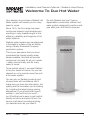
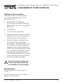
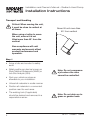
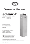
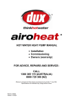
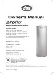
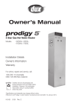
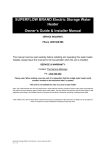
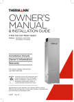
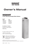
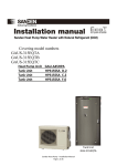
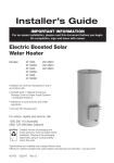
Installation and Owner’s Manual
Important INFORMATION
Read This Document First
On completion, sign and leave with owner
Heat Pump Water Heater
Model: R2FHG4HW0C
Installation Details
Owner’s Information
Warranty
For advice, repairs and service, call:
1300 365 115 (Australia)
0800 729 389 (New Zealand)
Carefully remove all packaging and
transit protection from the heater before
installation. Dispose of the packaging
responsibly using re-cycling facilities
where they exist.
This appliance must be installed by a licensed
tradesperson and in accordance with:
• Manufacturer’s instructions
• AS/NZS 3500.4 “National Plumbing &
Drainage Code Hot Water Supply Systems
– Acceptable Solutions”
• Adherence to local authority and OH&S
regulations
• Victorian PIC Requirements
Specifications and materials may change without notice.
Effective for Radiant® Heat Pump water heaters manufactured and sold after 1st January 2012.
H4121
025960
Rev. B
Installation and Owner’s Manual – Radiant® Heat Pump
Contents
Welcome To Dux Hot Water
1
Rough-In Diagram
2
Installation Instructions
3
Installation Declaration
12
Owner’s Manual
13
Troubleshooting
18
System Maintenance
20
Safety Information
21
Warranty
22
Other Information
25
Radiant® is a registered trademark of Dux Manufacturing Limited.
© Dux Manufacturing Limited 2012. All rights reserved.
H4121
025960
Rev. B
Installation and Owner’s Manual – Radiant® Heat Pump
Welcome To Dux Hot Water
Your decision to purchase a Radiant Hot
Water system will reward you for many
years to come.
Since 1915, the Dux range has seen
continuous research and development,
resulting in many breakthroughs in the
efficiency, reliability and longevity of hot
water systems.
Go with Radiant and you’ll have a
dependable, economical, efficient hot
water system designed to perform well,
year after year. And that’s a promise.
Radiant water heaters are manufactured
in Australia in a state-of-the-art facility,
using a Quality Endorsed Company
production system.
This is your assurance that you have
purchased the highest quality water
heater available, one that will provide
continuous hot water for all your needs
– safely, economically, and for many
years to come.
To be upfront about it, we want Radiant
to be your brand of choice. So you can
depend on us to provide more than just
a hot water system.
You can rely on Radiant products and
choose them with confidence. We’ll
make sure you have the information, the
quality and the innovation you’re looking
for, including the latest energy-saving
alternatives. If you should ever have a
problem – and we’ll bet you won’t –
you’ll find that we’re easy to get hold of,
friendly to talk to and quick to act. Our
service is all about providing anything
you need as soon as you need it.
H4121
025960
Rev. B
1
Installation and Owner’s Manual – Radiant® Heat Pump
Rough-In Diagram
632
Hot
1711
Tempering
Valve
1211
Net weight = 107kg
508
Cold
195
100
700
150
Allow 50% of the height of the
water heater for clearance
above to replace the anodes
150
Allow 700 mm clearance
above and 150mm
clearance to either side
of the unit
2
H4121
025960
Rev. B
Installation and Owner’s Manual – Radiant® Heat Pump
Installation Instructions
Regulatory Requirements
This water heater must be installed
by a licensed tradesperson, and in
accordance with:
•
AS/NZS3500.4.2 “National
Plumbing and Drainage Code Hot
Water Supply Systems – Acceptable
Solutions”.
•
AS/NZS3000.
•
Local authority regulations.
•
Outside Australia and New Zealand,
please refer to local plumbing and
building codes and regulations.
•
Notice to Victorian customers from
the Victorian Plumbing Industry
Commission – this water heater must
be installed by a licensed person as
required by the Victorian Building Act
(1993). Only a licensed person will give
you a compliance certificate, showing
that the work complies with all the
relevant Standards and only a licensed
person will have insurance protecting
their workmanship for 6 years.
Note: This water heater and
heat pump components are
not suitable for pool heating.
Specifications
The net weight of the heat pump is
107kg.
Dimensions are shown in the rough-in
diagram in this manual.
H4121
025960
Rev. B
3
Installation and Owner’s Manual – Radiant® Heat Pump
Installation Instructions
Transport and Handling
Critical: When moving the unit,
it must be close to vertical at
all times.
Never tilt unit more than
45˚ from vertical
When using a trolley to move
the unit, ensure it is not
tilted more than 45° from the
vertical.
Non-compliance will void
warranty and severely affect
product performance and
operation.
Step 1
• Arrive at site and conduct a safety
audit.
• Safety audits can also be known as
Work Method Statements (WMS) or
Job Site Analysis (JSA).
• Park your vehicle as close as
allowable to your installation.
Note: Do not commence
a job where the risks
cannot be controlled.
• Unload all materials in a safe manner.
• Position all materials in a convenient
position near the work area.
• The existing tank (if applicable)
should be drained and removed in a
responsible manner.
4
Note: Do not drain on to
grass or garden beds.
H4121
025960
Rev. B
Installation and Owner’s Manual – Radiant® Heat Pump
Installation Instructions
Placement of New Tank
Step 2
• The water heater must be installed
outdoors, close to the most
frequently used hot water outlet.
d installation pos
ition
ferre
Pre
Heat Pump
• Optimum installation location is on
the warmest side of house.
• The location must consider noise
impact on living areas. Avoid
positioning near bedrooms or
neighbours’ bedrooms. Although the
running noise level is very low (51
dB(A)) it can be expected that the
heat pump will run during the night.
• Adequate access must be available
to the relief valve and anodes.
• Safely position the new unit on a
level surface in accordance with all
plumbing and building regulations.
• A properly drained overflow tray
must be used where property
damage could occur from water
spillage. (See AS/NZS3500.4.2 for
further details.)
Install a plinth under the
water heater where the
water heater is subjected
to wet conditions
Note: The warranty does not
cover consequential damage
due to leakage of the water
heater.
H4121
025960
Rev. B
5
Installation and Owner’s Manual – Radiant® Heat Pump
Installation Instructions
• Allow 200m3 of free space
surrounding the unit. This provides
clear ambient airflow assisting the
product’s performance.
• The area must also be clear of debris
such as leaves and tree branches.
• Allow 700 mm clearance above and
150mm clearance to either side of
the unit as shown in the Rough-In
Diagram on page 2.
• Ensure there are no obstructions
placed on top of the unit.
• Total clearance required from ground
to install unit is approximately
2410mm.
Plumbing Connections
Step 3
• Refer to the Rough-In Diagram on
page 2 for detailed information on
position of plumbing.
• An approved isolating valve, nonreturn valve, line strainer (optional
but recommended), and union must
be fitted between the supply main
and the RP¾/20 socket in the water
heater.
• All fittings must be approved by the
relevant installation Authority.
6
Isolating Valve
(Spindle Vertical)
Cold water expansion
control valve
Drain
Cold Water
Inlet
Line
Strainer
Non-return
Valve
Union
Connection
Note: For S.A. and W.A., it
is a state requirement that
a cold water expansion
control valve be fitted on
the cold water supply line
between the non-return
valve and the water heater.
H4121
025960
Rev. B
Installation and Owner’s Manual – Radiant® Heat Pump
Installation Instructions
• This water heater is designed for
direct connection to water supply
pressures of no greater than 800kPa.
• Where the mains pressure can
exceed or fluctuate beyond 800kPa,
a pressure limiting device (complying
with AS1357) must be fitted.
PTR Valve
• Connect the supplied PTR valve
into the top socket marked “RELIEF
VALVE” and discharge according to
plumbing regulations.
• PTR Valves for the unit are rated at
1000kpa.
• The drain line from this valve must
run in a continuously downward
direction with the discharge end left
permanently open to atmosphere.
arning: A separate drain
W
line must be run for this relief
valve. It is not permitted to
couple drain lines from relief
valves into a single common
drain line.
• The PTR Valve is not intended to
enable connection of the water
heater to supplementary energy
sources such as solar panels or
slow combustion stoves (refer AS/
NZS 3500.4.2 for guidance on these
types of installations)
H4121
025960
Rev. B
7
Installation and Owner’s Manual – Radiant® Heat Pump
Installation Instructions
Cold and Hot Water Connections
• Connect the cold water pipe to the
storage tank, according to local
regulations and the Plumbing Code.
• The hot water line should be
connected to the hot water outlet.
Hot
Tempered
Tempering Valve
• A tempering valve is mandatory.
• Ensure it is commissioned correctly.
Incorrect commissioning can lead to
a lack of hot water.
Cold
• We recommend using an orange
top Reliance brand tempering valve.
Condensation Drain Line
• A condensation drain line is required
to be fitted to carry discharge clear
of water heater.
• Condensate drain line should not be
connected to the PTR Valve drain
line but can exit to the same point.
Insulation
• It is recommended that all hot
water lines are insulated with high
temperature, UV resistant 13mm
closed cell insulation.
8
H4121
025960
Rev. B
Installation and Owner’s Manual – Radiant® Heat Pump
Installation Instructions
Electrical Connections
Step 4
• A properly authorised electrical
contractor must connect the unit.
• The unit is rated at 10 amps (2
core and earth) so the power mains
supplying the unit must have a 10
amp minimum double pole circuit
breaker fitted.
• The electrical connection must
comply with local supply authority
regulations and AS3000.
• The unit must be connected to:
- CONTINUOUS TARIFF, single
phase 240 volt AC supply.
- Tariff 33 (QLD only), single phase
240 volt AC supply. • The mains AC supply connection is
located under a plate located on the
side of the tank.
Access
Cover
• A qualified electrician may remove
the access cover by undoing the two
screws on the cover and sliding the
cover downward to disengage it.
Caution: The water heater
must be filled with water
before turning on the
electricity supply.
H4121
025960
Rev. B
9
Installation and Owner’s Manual – Radiant® Heat Pump
Installation Instructions
Commissioning The System
Step 5
• Fill and pressurise the unit with water
BEFORE switching on.
Critical: Switching on the unit
without water will damage it.
• Turn on the power supply. The
Hotlogic control system will
then check the unit’s operating
parameters. If conditions are suitable
and there is enough energy available
in the surrounding air, the fan and
compressor will turn on.
• There will be a delay of approximately
30 seconds from the time the main
power is switched on before the
compressor and fan begin operating.
• The unit is self regulating so there are
no internal adjustments to be made
during commissioning.
• Bleed air from system through a hot
water tap not via the PTR Valve.
Power LED
• Ensure the Hotlogic unit is
displaying the green power LED
once unit has been switched on.
®
• If the Hotlogic® unit is not displaying
the green power LED, refer to the
table of Hotlogic Operational Codes
on page 13.
• Contact DUX Service 1300 165 115
if problems arise.
10
H4121
025960
Rev. B
Installation and Owner’s Manual – Radiant® Heat Pump
Installation Instructions
Conditioning Cycle
Step 6
• When the unit is operated for the first
time, it runs through a conditioning
cycle.
• Once this has occurred, it is
important to conduct a draw off
of hot water, and allow the unit
to re-heat prior to testing water
temperature.
• Do the following:
-- After filling the tank with water, allow
time for the initial heat up cycle.
-- Once its first heat up cycle is
complete, empty approximately
60 litres of hot water from the tank
through the PTR valve outlet.
-- Then allow the water in the tank to
re-heat.
-- Once the re-heat cycle is complete,
measure the water temperature at
the PTR outlet again.
-- The temperature will be
approximately 60º C.
• If for any reason the unit does not
start, the water is cold and the
Hotlogic unit is not displaying any LED
lights, an electrician should test that
power is available to the heat pump.
• Note: There are no installer
serviceable parts within the heat
pump module.
H4121
025960
Rev. B
11
Installation and Owner’s Manual – Radiant® Heat Pump
Installation Declaration
Location of Installation: ...........................................................................................
...............................................................................................................................
...............................................................................................................................
Tank Serial Number: ...............................................................................................
Tank Model Number: ..............................................................................................
Date Installed: ............................
Dux Hot Water terms and conditions of warranty will apply only if the below is
signed by the installer. This notifies Dux Hot Water that all the requirements of
proper installation have been carried out by the installer in accordance with the
commissioning checklist and all other requirements noted in this manual supplied
with the heat pump water heater.
Upon completion of installation, this document should be given to the home owner
in its entirety. When required by Dux Hot Water, the home owner will provide this
document as evidence that the installation of the heat pump water heater was
carried out in accordance with installation requirements.
Declaration
I have installed the heat pump water heater in accordance with the above
instructions. If the instructions have not been followed then I understand that the
terms and conditions of warranty will be void.
Name:.....................................................................................................................
Signed: . .................................................................................................................
Company: ..............................................................................................................
Date: .........................................
12
H4121
025960
Rev. B
Installation and Owner’s Manual – Radiant® Heat Pump
Owner’s Manual
Hotlogic Operational Codes
3
2
4
Hotlogic Components
5
1
6
7
8
9
LED 1
(Power)
LED 2
(Sensor)
Alternating
LED 3
(Output)
Off
To power
2
To compressor
3
Power LED
4
Sensor LED
5
Output LED
6
To ambient sensor
7
To pressure switch
8
To tank sensor
9
To fan
Explanation
Power on initialisation (LEDs blink Red-Green alternately)
Green
Green
Green
Flashing Red
Off
Sensor error (1 blink = ambient sensor, 2 blinks = tank sensor)
Green
Green
Red
Over Pressure Switch tripped
H4121
025960
Rev. B
Green
1
Fan on (Compressor on/off)
13
Installation and Owner’s Manual – Radiant® Heat Pump
Owner’s Manual
Refrigeration View
Cut-through View
Main Component View
14
H4121
025960
Rev. B
Installation and Owner’s Manual – Radiant® Heat Pump
Owner’s Manual
Safety
This appliance is not intended for use
by persons (including children) with
reduced physical, sensory or mental
capabilities, or lack of experience and
knowledge, unless they have been given
supervision or instruction concerning
use of the appliance by a person
responsible for their safety.
Children and animals should be
supervised to ensure that they do not
interfere with the appliance.
How Does The Heat Pump
Module Work?
A heat pump uses complex
thermodynamic principles to extract
energy from ambient air and transfer this
energy to water that is in contact with
the unit’s immersed heat exchanger.
The heat pump’s operational principles
are similar to those used in a normal
domestic refrigerator, except in reverse.
In a refrigerator, heat energy is drawn
from inside the refrigerator (making things
cold), concentrated by the compressor
then dissipated to the atmosphere via the
condenser coil located on the back of the
refrigerator cabinet.
In a heat pump system, outside air
is drawn into the unit and across an
evaporator coil by a fan. The evaporator
coil captures the energy in the air and
transfers that to cold liquid refrigerant,
contained inside the evaporator, causing
the refrigerant to increase in temperature
and evaporate into a warm gas.
H4121
025960
Rev. B
The warm gas on exiting the evaporator
passes into a compressor where
compression causes the temperature of
the gas to increase further, becoming a
superheated (hot) gas.
The superheated gas is pumped from
the compressor to a water immersed
condenser coil, where it gives up its
heat energy to the water. When the
superheated gas gives up energy, it
condenses back to a liquid, and on
exiting the condenser coil, it passes
through an expansion control valve (TX
valve).
The TX valve acts as an automatically
adjusting tap that controls the amount of
liquid refrigerant that is allowed to pass,
once more, into the evaporator. This
is necessary to constantly match the
amount of liquid entering the evaporator
to the available energy in the air passing
through the evaporator so that the entire
liquid refrigerant that enters evaporates
and exits as a gas only.
How Do I Operate The System?
The operation of your water heater is
fully automatic, so you only need to
connect the water and electricity supply
and then turn on the electricity.
The heat pump module is electrically
connected to the storage tank and
will start automatically when the water
temperature in the storage tank falls
below 55°C and continue to run until the
water temperature of the complete tank
15
Installation and Owner’s Manual – Radiant® Heat Pump
Owner’s Manual
has been increased to 60°C or slightly
above. To condition the unit properly
allow the heat pump to go through one
heat up cycle, before use, then wait 24
hours before using the hot water.
Water Quality
Your water heater has been manufactured
to suit all water conditions in “All Water
Areas” present in Australia. Please note
that harsh water supplies can have a
detrimental effect on a water heater
and its life expectancy. If you are unsure
about your water quality, you can obtain
information from your local water supply
authority.
Water can also contain material known
to create lime scale where lime scale
can build up and block safety fittings.
One measure of this water quality is
known as the saturation index. If the
saturation index is greater than 0.40 and
therefore subject to lime scale, a cold
water expansion control valve should
be fitted to the unit, as shown in the
diagram on page 6.
How Long Will The Heat Pump Run
Each Day?
The length of time that the unit will run
each day will vary dependent upon the
amount of hot water being used by the
household and the average outdoor
ambient temperature and humidity.
Generally the unit will run longer in
winter and at night when the outside air
temperature contains less energy.
16
What Is Subzero
(De-icing Function)?
Depending on the level of humidity, ice
may begin to form at around 5°C on the
evaporator coil, which has the potential
to affect the system’s performance.
The system’s Hotlogic controller
determines if conditions conducive to
icing exist, and triggers the de-icing
cycle as a result.
The de-icing cycle interrupts the flow
of heated refrigerant, shuts down the
compressor, and runs the fan in reverse,
drawing air through the evaporator coil
and past the louvres. It is this airflow
which de-ices the evaporator coil. Once
de-icing has occurred, the system
allows the heated refrigerant to flow, and
heating recommences.
Does The Heat Pump Need Sunlight To Operate?
Heat pump water heaters extract their
energy from the surrounding air and
not from sunlight. For this reason they
can efficiently produce hot water any
time day or night and even on cloudy or
overcast days. It is not uncommon for
your system to operate during the night.
Caution: All water heaters have
the ability to produce hot water
in a surprisingly short time.
To reduce the risk of scald
injury, it is mandatory under
the requirements of Australian
Standards AS3500 that an
H4121
025960
Rev. B
Installation and Owner’s Manual – Radiant® Heat Pump
Owner’s Manual
Australian Standards approved
temperature control valve be
fitted to the hot water supply
pipe work. This valve should
be checked at regular intervals
to ensure its operation and
settings remain correct.
Why Is There Condensation Coming From The Unit?
Condensation production is normal
for all devices that use refrigeration
principles. Air conditioners are a good
example of systems that produce water
condensation.
Condensation occurs when relatively
warm moist air passes through the
cold evaporator. Moisture contained in
the air condenses (deposits) onto the
evaporator fins, then runs down into
the drainage system located under the
evaporator. It is this water that you see
flowing from the condensate drain of the
system.
The amount of condensation will vary
with the humidity of the location, so the
amount of condensate that flows from
the module will also vary.
plumber to attach the condensate drain
line away from the heater.
What Should I Do During Holidays?
If you are going to be away for a week
or more, it is advisable to turn off the
electricity supply to the system. While
there is no damage likely if the electricity
is left on, you will consume energy
through storage tank heat losses which
can be avoided.
Warning: If the hot water system is
not used for two weeks or more, a
quantity of hydrogen gas, which is highly
flammable, may accumulate in the water
heater. To dissipate this gas safely, it is
recommended that a hot tap be turned
on for several minutes at a sink, basin
or bath, but not a dishwasher, clothes
washer, or other appliance. During this
procedure, there must be no smoking,
open flame or any other electrical
appliance operating nearby. If hydrogen
is discharged through the tap, it will
probably make an unusual noise similar
to air escaping.
When condensate is created, it runs
into the “Condensate Tray” which sits
on top of the storage tank. This then
runs out through the “Condensate
Drain” which is a feature of the tray.
A plastic drain pipe is attached to this
drain allowing easy access for the
H4121
025960
Rev. B
17
Installation and Owner’s Manual – Radiant® Heat Pump
Troubleshooting
What Should I Check Before Making A Service Call?
If, after checking the troubleshooting
points in the following section, the
problem has not been identified, please
contact the distributor from whom you
purchased the system.
faulty thermostat. Turn off the electricity
supply, turn off the water, and contact
your Dux agent.
Note: It is important to know that there
are no user serviceable components
in the system, so it is recommended
that no covers be removed and no
adjustments made to the system
settings by anyone other than an
authorised representative.
•
Do you have the correct size water
heater for your requirements? Sizing
details are available from your Dux
supplier.
•
Is one outlet (such as the shower)
using more hot water than you think?
•
Carefully review the family’s hot
water usage and if necessary
check the shower flow rates with a
bucket, measuring the amount of
water used over that period of time.
If it is not possible to adjust water
usage patterns, an inexpensive flow
control valve can easily be fitted to
the shower outlet.
•
Consider that during night time
heating, the time taken to heat the
tank can take longer (less energy in
the air) so you may find that the tank
has not fully recovered from a period
of heavy usage the previous evening.
•
Consider that often the hot water
usage of showers, washing machines
and dishwashers can be under
estimated. Review these appliances
to determine if your daily usage is
greater than the storage volume of
your water heater. For example, if
Water Discharge From Pressure &
Temperature Relief Valve (PTR)
It is not unusual for a small quantity of
water to discharge during the heating of
water in your storage tank. The amount
of discharge will depend on hot water
usage and size of the storage tank.
As a guide, it will discharge 3% of the
storage capacity of water in the heating
period.
Continuous Trickle From PTR
This is most likely due to a build up of
foreign matter. In this case, try gently
raising the easing lever on the PTR Valve
for a few seconds, then release gently.
This may dislodge a small particle of
foreign matter and rectify the fault.
Steady Flow From PTR
This may be caused by excessive water
supply pressure, a faulty PTR Valve, or a
18
No Hot Water
• Is the Pressure & Temperature Relief
Valve discharging too much water?
H4121
025960
Rev. B
Installation and Owner’s Manual – Radiant® Heat Pump
Troubleshooting
you have a 250 litre storage tank
and you are using 390 litres of
water, it is possible that there will be
certain times of the day where there
is insufficient hot water. It is also
advisable to inspect tap washers etc.
for leakage and replace if necessary.
High Electricity Bills
• Is the Pressure & Temperature Relief
Valve discharging too much water?
•
Is one outlet (e.g. the shower) using
more hot water than you think?
•
Is there a leaking hot water pipe or
dripping hot water tap? A small leak
can waste a large quantity of hot
water.
•
Replace faulty tap washers and
have your plumber rectify any
leaking pipe work.
The Unit Does Not Run
Check that the power supply is turned
on and that the house circuit breakers or
fuses are on and operational.
H4121
025960
Rev. B
19
Installation and Owner’s Manual – Radiant® Heat Pump
System Maintenance
The heat pump water heater is designed
to eliminate system maintenance other
than that detailed in this manual.
where the potable water has a
TDS greater than 600 ppm, this
service is recommended every 3
years). All models are equipped
with 2 sacrificial anodes, accessible
through the top cover.
Personally inspecting or servicing any
part of the system is not recommended.
Should you decide to personally inspect
the system, it is essential that you
observe all normal safety practices.
Most importantly, the electricity
supply must be turned OFF.
Every 5 years, you should contact the
local service agent to replace all safety
valves and anodes to ensure continued
system life and operational safety.
Six Monthly Service – By Owner
Operate the Pressure & Temperature
Relief Valve for approximately 10
seconds by operating the easing lever
on the valve to ensure water is relieved
to waste through the relief drain pipe.
Check to ensure the valve closes
correctly.
Five Year Service – By Authorised
Personnel Only
The five yearly services should be
carried out by a licensed tradesperson
where it is recommended that this
service be carried out by your local Dux
agent.
The service should include the following:
•
Replace the Pressure &
Temperature Relief Valve.
•
Replace the anodes (in locations
20
•
Flush the water heater by doing the
following:
(i) Turn off the power.
(ii) Turn off the cold water supply to the
water heater at the isolating valve.
(iii) Gently operate the easing lever on
the Pressure & Temperature Relief
Valve to release the pressure in the
water heater.
(iv) Disconnect the cold water inlet
union to the heater and attach a
drain hose.
(v) Gently operate the Pressure &
Temperature Relief Valve to let air
into the heater and allow water to
escape through the hose.
(vi) To flush the heater, carry out steps
(i) to (iv) above. Disconnect the hot
water inlet union and attach a water
supply hose to the heater. Turn on
the water supply.
(vii) Flush the heater until clear water
appears, then reconnect all fittings,
fill the heater and restore the
electricity supply.
Draining the Water Heater
To drain the water heater, follow steps i
to v above until no more water escapes
from the appliance.
H4121
025960
Rev. B
Installation and Owner’s Manual – Radiant® Heat Pump
Safety Information
For safe performance this water heater
is fitted with:
•
a Hotlogic controller
•
a refrigerant over-pressure cut-out
•
a compressor thermal cut-out
•
a combination Pressure &
Temperature Relief (PTR) Valve.
Important: These devices
must not be tampered with
or removed. The water heater
must not be operated unless
these devices are fitted and in
working order.
Electrical Cover
The electrical cover should be removed
only by an electrician. The electrical
power supply switch must be turned
off and the fuse removed at the main
electrical supply switchboard before
the water heater’s electrical cover is
removed.
H4121
025960
Rev. B
PTR Valve
The PTR Valve should be checked for
adequate performance or replaced at
intervals not exceeding 5 years, or less in
areas where local regulations apply.
The lever on the relief valve should be
pulled to operate the valve at least once
every six months.
Danger: Failure to operate
the relief valve easing gear at
least once every six months
may result in the water
heater exploding. Continuous
leakage of water from the
valve may indicate a problem
with the water heater.
Note: The PTR valve and the drain
outlet pipe must not be sealed or
blocked. It is normal for the valve to
overflow during heating cycles.
21
Installation and Owner’s Manual – Radiant® Heat Pump
Warranty
Radiant Hot Water Unit
Manufactured by Dux Manufacturing
Limited (“Dux”)
Terms of Warranty and Replacement
Guarantee
All Radiant water heaters manufactured
and sold after 1 January 2011 are
backed by a comprehensive one (1) year
full parts and labour warranty (conditions
apply – see below).
Furthermore, the Radiant tank includes
a guarantee to replace your hot water
unit if the inner cylinder fails within five
(5) years (conditions apply – see below).
The terms of the Warranty and
replacement guarantee are set out
below.
1 Year Comprehensive Warranty
Your hot water system and its
components (“Unit”) are covered by
1 year (parts and labour) warranty
against defective factory materials or
workmanship.
This warranty period commences from
the date of installation of the Unit providing you have proof of this installation
date. Where the date of completion of
installation is not known or cannot be
proven, then this warranty will commence
one (1) month after the date of manufacture (refer to the data label on the unit).
22
2 Year Refrigerant Components
Replacement Guarantee
If a refrigerant component fails, within a
further one (1) year after the end of the
initial warranty period, Dux will provide a
full refrigerant parts replacement guarantee
for these components, at the nearest
approved Dux agent or Dux office to the
owner’s home. Under this replacement
guarantee, the transport, installation and
labour costs of delivering the replacement
components will be responsibility of the
owner of the existing water heater.
5 Year Replacement Guarantee
If an inner cylinder fails on a Radiant
hot water unit within a further four (4)
years after the end of the initial one (1)
year warranty period, Dux will provide a
free replacement hot water unit at the
nearest approved Dux agent or Dux
office to the owner’s home. Under this
replacement guarantee, the transport,
installation and labour costs of delivering
the replacement hot water unit and
removing and replacing the existing
hot water unit with the replacement hot
water unit will be the responsibility of the
owner of the existing hot water unit.
Conditions of Warranty and Replacement Guarantee
The benefits provided to you by the
warranty and replacement guarantee
(collectively “Warranty”) are in addition
to the guarantees and other rights and
remedies available to you under the
Australian Consumer Law (“ACL”).
H4121
025960
Rev. B
Installation and Owner’s Manual – Radiant® Heat Pump
Warranty
If the Unit fails to conform to this Warranty
during the applicable period, Dux will
replace any failed component or where
necessary, in the absolute discretion
of Dux, replace the Unit free of charge
including reasonable labour costs incurred
in normal business working hours.
This Warranty only applies to defects
which have arisen solely from faulty
materials or workmanship in the Unit
and does not apply to other defects
which may have arisen as a result of,
without limitation, the following: accidental
damage, abuse, misuse, maltreatment,
abnormal stress or strain, harsh or adverse
water conditions including excessive water
pressure or temperature, neglect of any
kind or otherwise as a result of any use of
the Unit contrary to the product manual
or other instructions provided by Dux.
Alterations or repair of the Unit other than
by an accredited and licensed service
agent or technician are not covered.
Attachment of accessories or use of non
genuine replacement parts other than
those manufactured or approved by Dux
are not covered by this Warranty.
This Warranty applies only to the Unit and
does not cover any ancillary plumbing or
electrical parts supplied by the installer
such as pressure limiting valve, tempering
valve, line strainer, stop cocks, non-return
valve, electrical switches, pumps or fuses,
or faulty installation.
The Unit must be installed by a licensed
plumber in accordance with information
H4121
025960
Rev. B
set out in the Owner’s Manual and/
or Installer’s Guide supplied with the
Unit and/or any relevant statutory
requirements.
In addition to this Warranty, certain
legislation (including the ACL) may give you
rights which cannot be excluded, restricted
or modified. This Warranty must be read
subject to such legislation and nothing in
this Warranty has the effect of excluding,
restricting or modifying those rights.
If Dux fails to meet a guarantee under the
ACL, your remedy for such failure may be
limited to any one or more of the following:
•
replacement of the Unit;
•
repair of the Unit;
•
refunding the cost of the Unit;
•
payment of reasonable costs of
having the Unit repaired;
•
payment in respect of the reduced
value of the Unit.
Any defective part of the Unit must be
returned to the point of sale before
replacement can be considered under
the terms of this Warranty. If the costs
of returning any defective parts are
unreasonable, please contact Dux on
1300 365 115 (Australia) or 0800 729
389 (New Zealand) so that we can
arrange a collection if appropriate.
Warranty claims can be made at the
point of sale or by posting or faxing a
warranty claim to Dux (contact details
23
Installation and Owner’s Manual – Radiant® Heat Pump
Warranty
listed below) within one (1) month of the
appearance of a defect. Warranty claims
under this extended warranty must
include the following details:
•
Date of Purchase;
•
Location of Purchase;
•
Proof of Purchase;
•
Date of Installation;
•
Contact Details;
•
Product Serial Number
Contact Details
Dux’ contact details are as follows:
Business Address:
Dux Manufacturing Limited
Lackey Road
Moss Vale, NSW, 2577
Australia
Telephone:
doors, walls or special equipment and/
or excessive labour, at the determination
of Dux, to make the Unit accessible for
repair or replacement.
As required by legislation, including
under the ACL, any claims for damage
to furniture, carpets, walls, foundations
or any other consequential loss either
directly or indirectly due to defects
of any kind in a Unit will only be met
by Dux where the damage could be
considered reasonably foreseeable.
Our goods come with guarantees that
cannot be excluded under the Australian
Consumer Law. You are entitled to a
replacement or refund for a major failure
and for compensation for any other
reasonably foreseeable loss or damage.
You are also entitled to have the goods
repaired or replaced if the goods fail to
be of acceptable quality and the failure
does not amount to a major failure.
1300 365 115 (Australia)
0800 729 389 (New Zealand)
Facsimile:
(61 2) 4868 0257
Email:
[email protected]
Note: If the Unit is located in a
position that does not comply with
the installation instructions or relevant
statutory requirements, then this
Warranty does not cover major
dismantling or removal of cupboards,
24
H4121
025960
Rev. B
Installation and Owner’s Manual – Radiant® Heat Pump
Other Information
Product Warranty is applicable only in Australia and New Zealand.
See page 22 for terms of warranty.
Privacy Act Amendment (2000): If and whenever warranty service is required, your personal
details will be given to an Authorised Dux Service Agent only for the express purpose
of carrying out the arranged warranty service work agreed by you the client and Dux
Manufacturing Limited.
Your Details
For future convenience, fill in the following details and retain with your original invoice for your
own records.
Surname:......................................Given Name(s):...................................................
Address:..................................................................................................................
Town/Suburb:..........................................................................................................
State/Territory:............................. Postcode:....................
Date of Purchase:.......................... Purchased From:.............................................
Model:.................................. Serial Number (located on back cover):.....................
Date of Manufacture:..............................................................................................
(Details on Data Label on water heater)
Installer’s Details:
Date of Installation:......................... Installer’s Name:.............................................
Address:..................................................................................................................
Installer’s Signature:...................................................................................
Service Details:
Date of Service:......................... Serviced By:..........................................................
Work Carried Out:......................................................................................................
..................................................................................................................................
..................................................................................................................................
Signature of Service Agent:........................................................................
H4121
025960
Rev. B
25
Installation and Owner’s Manual – Radiant® Heat Pump
Heat Pump Water Heater
For advice, repairs and service, call:
1300 365 115 (Australia)
0800 729 389 (New Zealand)
Please Register Your Water Heater
Please take a moment to fill
out your details for warranty
registration at:
www.dux.com.au/warranty
or use your smartphone to scan this code:
Preventative Maintenance
Maintaining your hot water system
will help extend its lifespan and
reduce running costs.
Please register for preventative
maintenance at:
This will ensure all your current details are
registered with us for prompt warranty
service if required.
www.dux.com.au/maintenance
Serial Number
H4121
025960
Rev. B