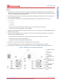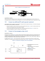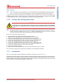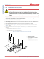
1
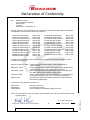
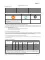
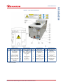
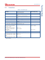
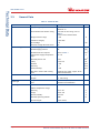
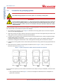
A546–00–880 Issue E Original Instruction Manual iGX Dry Pumping Systems Description iGX100L 200 V – 230 V 50/60 Hz iGX100L 380 V – 460 V 50/60 Hz iGX100L 200 V – 230 V 50/60 Hz SS iGX100L 380 V – 460 V 50/60 Hz SS iGX600L 200 V – 230 V 50/60 Hz iGX600L 380 V – 460 V 50/60 Hz iGX600L 200 V – 230 V 50/60 Hz SS iGX600L 380 V – 460 V 50/60 Hz SS iGX100N 200 V – 230 V 50/60 Hz iGX100N 380 V – 460 V 50/60 Hz iGX100N 200 V – 230 V 50/60 Hz SS iGX600N 200 V – 230 V 50/60 Hz iGX600N 380 V – 460 V 50/60 Hz Item Number A546-10-958 A546-10-959 A548-10-958 A548-10-959 A546-30-958 A546-30-959 A548-30-958 A548-30-959 A546-11-958 A546-11-959 A548-11-958 A546-31-958 A546-31-959 Description iGX1000N 200 V – 230 V 50 Hz iGX1000N 380 V – 460 V 50 Hz iGX1000N 200 V – 230 V 50/60 Hz SS iGX1000N 200 V - 230 V 50/60 Hz SS iGX100M 200 V – 230 V 50/60 Hz iGX100M 380 V – 460 V 50/60 Hz iGX100M 200 V – 230 V 50/60 Hz SS iGX100MTi 200 V – 230 V 50/60 Hz iGX100MTi 380 V – 460 V 50/60 Hz iGX100MTi 200 V – 230 V 50/60 Hz SS iGX100MTi 200 V – 230 V 50/60 Hz SS iGX600M 200 V – 230 V 50/60 Hz iGX600M 380 V – 460 V 50/60 Hz iGX600M 200 V – 230 V 50/60 Hz SS iGX600M 200 V – 230 V 50/60 Hz SS Item Number A546-81-958 A546-81-959 A548-81-958 A543-81-958 A546-12-958 A546-12-959 A548-12-958 A546-48-958 A546-48-959 A548-48-958 A543-48-958 A546-32-958 A546-32-959 A548-32-958 A543-32-958 Declaration of Conformity We, Edwards Limited, Crawley Business Quarter, Manor Royal, Crawley, West Sussex, RH10 9LW, UK declare under our sole responsibility, as manufacturer and person within the EU authorised to assemble the technical file, that the product(s) iGX100L 200-230V 50/60Hz iGX100L 380-460V 50/60Hz iGX100L 200-230V 50/60Hz SS iGX100 380-460V 50/60Hz SS iGX600L 200-230V 50/60Hz iGX600L 380-460V 50/60Hz iGX600L 200-230V 50/60Hz SS iGX600L 200-230V 50/60Hz SS iGX100N 200-230V 50/60Hz iGX100N 380-460V 50/60Hz iGX100N 200-230V 50/60Hz SS iGX600N 200-230V 50/60Hz iGX600N 380-460V 50/60Hz A546-10-958 A546-10-959 A548-10-958 A548-10-959 A546-30-958 A546-30-959 A548-30-958 A548-30-959 A546-11-958 A546-11-959 A548-11-958 A546-31-958 A546-31-959 iGX1000N 200-230V 50/60Hz iGX1000N 380-460V 50/60Hz iGX1000N 200-230V 50/60Hz SS iGX100M 200-230V 50/60Hz iGX100M 380-460V 50/60Hz iGX100M 200-230V 50/60Hz SS iGX100MTi 200-230V 50/60Hz iGX100MTi 380-460V 50/60Hz iGX100MTi 200-230V 50/60Hz SS iGX600M 200-230V 50/60Hz iGX600M 380-460V 50/60Hz iGX600M 200-230V 50/60Hz SS A546-81-958 A546-81-959 A548-81-958 A546-12-958 A546-12-959 A548-12-958 A546-48-958 A546-48-959 A548-48-958 A546-32-958 A546-32-958 A548-32-958 to which this declaration relates is in conformity with the following standard(s) or other normative document(s) EN1012-2:1996, A1: 2009 EN61010-1: 2010 EN 61326-1: 2006 UL61010A: 2002 SEMI S2-0703 Compressors and Vacuum Pumps. Safety Requirements. Vacuum Pumps Safety Requirements for Electrical Equipment for Measurement, Control and Laboratory Use. General Requirements Electrical equipment for measurement, control and laboratory Use. EMC requirements. General requirements. Safety requirements for electrical equipment for measurement, Control and laboratory use – Part 1: General requirements Environmental Health and Safety Guideline for semiconductor Manufacturing Equipment. and fulfils all the relevant provisions of 2006/42/EC 2006/95/EC 2004/108/EC Machinery Directive Low Voltage Directive Electromagnetic Compatibility (EMC) Directive 21.10.2013, Burgess Hill Mr Mark Hope, Global Technical Support Manager Date and Place This product has been manufactured under a quality system certified to ISO9001:2008 P200-01-960 Issue C Note: This declaration covers all product serial numbers from the date this Declaration was signed onwards. P601-00-700 Issue D Product Information for China Equipment types: iH Vacuum Pump Range GX Vacuum Pump Range DiHxK Vacuum Pump Range iF Vacuum Pump Range iHxK Vacuum Pump Range DiFxK Vacuum Pump Range iGX Vacuum Pump Range iFxK Vacuum Pump Range EPX Vacuum Pump Range iPX Vacuum Pump Range iQ/QDP/QMB Vacuum Pump Ranges iL Vacuum Pump Range Product Label Overshipper Label Pallet Marking 20 NW CB Indicates toxic or hazardous substance contained in at least one of the homogeneous materials used for this part is above the limit requirement in SJ/T11363-2006. Environmental Protection Use Period is 20 years. Recyclable Cardboard Recyclable Natural Wood Materials Content Declaration & Environmental Protection Use Period The Chinese regulatory requirement on the Control of Pollution Caused by Electronic Information Products No. 39 (also known as ‘China RoHS’) mandates that manufacturers of certain categories of electronic products sold in China after 1st March 2007 – Mark the product and packaging Define the Product’s Environment Protection Use Period (EPUP) Provide a Materials Content Declaration. Environmental Protection Use Period (EPUP) This is the period in years during which the toxic or hazardous substances or elements contained in this product will not leak or mutate under normal operating conditions so that the use of such electronic information products will not result in any severe environmental pollution, any bodily injury or damage to any assets. The Environmental Protection Use Period is 20 years for this product. For the purposes of EPUP, normal operating conditions are considered to be use in accordance with the product’s instruction manual. Materials Content Declaration Part name Toxic or Hazardous Substances and Elements Hexavalent Cadmium Polybrominated Chromium (Cd) biphenyls (PBB) (Cr VI) X X O Polybrominated diphenyl ethers (PBDE) O Lead (Pb) Mercury (Hg) Cartridge O O Enclosure Electronics and Controls Cooling system O O X X O O X O X X O O O O X X O O Purge system O O X X O O O: Indicates that this toxic or hazardous substance contained in all of the homogeneous materials for this part is below the limit requirement in SJ/T11363-2006. X: Indicates that this toxic or hazardous substance contained in at least one of the homogeneous materials used for this part is above the limit requirement in SJ/T11363-2006. Note 1. Table applies to all product types listed above. This page has been intentionally left blank. A546–00–880 Issue E CG 01/14 Section Page 1 Introduction ....................................................................................... 1 1.1 1.2 1.3 1.4 1.5 Scope and definitions ................................................................................................... 1 Applications ............................................................................................................... 2 The iGXL system ......................................................................................................... 2 Priority of control ........................................................................................................ 4 Active utility control .................................................................................................... 5 2 Technical Data .................................................................................... 7 2.1 2.2 2.3 2.4 2.5 General technical data .................................................................................................. 7 Electrical Data ........................................................................................................... 8 Loading .................................................................................................................... 8 Connections ............................................................................................................... 9 General Data ............................................................................................................ 10 3 Installation ....................................................................................... 11 3.1 3.2 3.3 3.4 3.5 3.5.1 3.5.2 3.6 3.7 3.8 3.9 3.10 3.11 3.12 3.13 Locate the dry pumping system ...................................................................................... 12 Lubrication ............................................................................................................... 13 Connect the iGX system to the vacuum/exhaust system and interstage connection (if fitted) ............13 Connect to the factory extraction system (optional) .............................................................14 Connect the nitrogen supply (if provided) .......................................................................... 14 Flammable/pyrophoric materials .................................................................................... 14 Gas Purges ............................................................................................................... 15 Leak-test the iGX system ..............................................................................................15 Connect the electrical supply ......................................................................................... 16 Connect an additional RF earth (ground) (optional) ..............................................................18 Connect to the emergency stop circuit ............................................................................. 18 Connect the cooling water hoses ..................................................................................... 19 Accessories ............................................................................................................... 19 Commission the iGX system ...........................................................................................20 Install additional safety equipment .................................................................................. 22 4 Operation ........................................................................................ 23 4.1 4.2 4.3 4.4 4.5 4.6 4.7 4.8 Start-up .................................................................................................................. 23 Status indicators ........................................................................................................24 Manual shut-down ......................................................................................................24 Automatic shut-down ..................................................................................................25 Unplanned shutdown and alarms ..................................................................................... 25 Emergency stop .........................................................................................................25 Restart the pump after an emergency stop or automatic shut-down .......................................... 26 Single equipment monitor (SEM) ..................................................................................... 26 5 Maintenance ..................................................................................... 27 5.1 5.2 5.3 5.4 Safety and maintenance frequency .................................................................................. 27 Relocate the system for maintenance ............................................................................... 28 Draining the cooling water ............................................................................................29 Cleaning the pump ......................................................................................................30 6 Transportation, Storage and Disposal ....................................................... 31 6.1 6.2 Transportation ..........................................................................................................31 Storage ................................................................................................................... 31 © Edwards Limited 2014. All rights reserved. Edwards and the Edwards logo are trade marks of Edwards Limited. Page i Contents Contents A546–00–880 Issue E Contents 6.3 Disposal ................................................................................................................... 31 7 Service, Spares and Accessories .............................................................. 33 7.1 7.2 7.3 Introduction ............................................................................................................. 33 Service .................................................................................................................... 33 Ordering accessories ...................................................................................................34 For return of equipment, complete the HS Forms at the end of this manual. Illustrations Figure 1 2 3 4 5 6 7 8 9 10 11 12 13 14 Page ii Page iGX Applications chart .................................................................................................. 2 The controls/connectors ................................................................................................ 3 The rear status panel LED indicators ................................................................................. 4 The front panel controls ................................................................................................ 4 Priority of control ........................................................................................................ 5 Centre of gravity and levelling foot loads ........................................................................... 8 System arrangment to reduce effective footprint (if required) ................................................. 12 High and low volt coding pin arrangement ......................................................................... 17 Method for connecting phase wires .................................................................................. 18 Connections to emergency stop circuit (systemable) .............................................................18 Installing 3/8" quick connect fittings (provided) ................................................................... 20 Gas module access panel ..............................................................................................21 Flow tube (14 slm) ......................................................................................................21 Flow tube (4 slm) .......................................................................................................22 © Edwards Limited 2014. All rights reserved. Edwards and the Edwards logo are trade marks of Edwards Limited. A546–00–880 Issue E Table 1 2 3 4 5 6 7 8 Page Technical data ........................................................................................................... 7 Technical data ........................................................................................................... 7 Electrical data ............................................................................................................ 8 Centre of gravity and levelling foot loads (Refer to Figure 6) .................................................... 8 iGX connector types ..................................................................................................... 9 Technical data ..........................................................................................................10 Safety sensors ...........................................................................................................25 Accessories ............................................................................................................... 34 Associated publications Publication title Vacuum pump and vacuum system safety Publication number P400–40–100 Trademark credits Fomblin® is a registered trademark of Ausimont SpA. © Edwards Limited 2014. All rights reserved. Edwards and the Edwards logo are trade marks of Edwards Limited. Page iii Contents Tables A546–00–880 Issue E This page has been intentionally left blank. Page iv © Edwards Limited 2014. All rights reserved. Edwards and the Edwards logo are trade marks of Edwards Limited. A546–00–880 Issue E Introduction 1.1 Scope and definitions This manual provides installation, operation and maintenance instructions for the Edwards iGX dry pumping systems. The pump must be used as specified in this manual. Read this manual before installing and operating the pump. Important safety information is highlighted as WARNING and CAUTION instructions; these instructions must be obeyed. The use of WARNINGS and CAUTIONS is defined below. WARNING Warnings are given where failure to observe the instruction could result in injury or death to people. CAUTION Cautions are given where failure to observe the instruction could result in damage to the equipment, associated equipment and process. The units used throughout this manual conform to the SI international system of units of measurement The following warning labels are on the pump: Warning – refer to accompanying documentation. Warning – risk of electric shock. Warning – hot surfaces. Warning – moving parts present. Warning – heavy object. Warning - pressurised. RF earth (ground). Warning - use protective equipment. © Edwards Limited 2014. All rights reserved. Edwards and the Edwards logo are trade marks of Edwards Limited. Protective earth (ground). Warning - Risk of explosion. Page 1 Introduction 1 A546–00–880 Issue E Introduction The pressurised and risk of explosion warnings only appear in this manual. Material Safety Data Sheets for chemicals supplied by Edwards can be obtained by contacting Edwards. 1.2 Applications If using the iGX system on an application for which it is not suitable (refer to Figure 1), the warranties may invalidate. If in doubt, contact Edwards for advice as to the suitability of the iGX system for any particular application. Figure 1 - iGX Applications chart 1.3 The iGXL system Pumping a chemical that will attack the materials in contact with these process materials may, over time, result in the internal contents of the pump becoming exposed to the external environment, which may constitute a safety hazard. If in doubt, contact Edwards for advice as to the suitability of this pump for any particular application. It is also a feature of this pump design that process gases are contained within the gearbox. This pump is not suitable for use with flammable, hazardous, toxic or corrosive gases or material. Page 2 © Edwards Limited 2014. All rights reserved. Edwards and the Edwards logo are trade marks of Edwards Limited. A546–00–880 Issue E Introduction Figure 2 - The controls/connectors Item 1 2 3 4 * Control/connector identification Protective earth (ground) M5 Electrical supply connection Rear status panel Item 8 9 10 5 Comms 4 - MicroTIM connection (if fitted) Ethernet active LED 11 12 6 Ethernet installed LED 7 Comms 3 Ethernet connection Control/connector identification Comms 2 - LON module connection Comms 1 - System control/ PDT 2 connection Gate valve interface (EMO on T variant) EMS* 15 16 17 18 Pumped gas inlet connection RF earth (ground) cable 23 Control/connector identification cooling water supply connection Castors (3 off) 24 Levelling feet (4 off) 25 cooling water return connection RF earth (ground) stud M6 27 28 Control/connector identification Lifting eyebolt Item 13 Accessory module interface* GRC interface* 20 Interstage connection (if fitted) Seismic bracket (if fitted, 4 off) Gas Module access panel 14 Extraction port 21 Nitrogen purge port 19 Item 22 26 Exhaust gas outlet connection Leak-test port not on T variants © Edwards Limited 2014. All rights reserved. Edwards and the Edwards logo are trade marks of Edwards Limited. Page 3 A546–00–880 Issue E Introduction Figure 3 - The rear status panel LED indicators Item 1 2 3 4 5 Indication Power OK (green) Running (green) Warning (Amber) Alarm (Red) Tool control (Green) Figure 4 - The front panel controls Item 1 2 3 4 5 * 1.4 Indication * EMS button Start button Stop button AUC LED (green) Local control button/LED (green) Item 6 7 8 9 10 Indication Alarm LED (red) Warning LED (amber) Running LED (green) Power OK LED (green) Comms 5 pump display terminal (PDT 1) connection Not on T variants Priority of control The iGX system can be controlled by a number of modules: the Pump Display Terminal (PDT), from the tool through the MicroTIM, or from the front panel local control membrane (refer to Figure 4). Only one of these can have control of the iGX system at any one time. That is, once one of these has control of the iGX system, control requests from the other are denied. The PDT indicates who is in control. LEDs are also provided on the rear panel, front panel or PDT, which illuminate to indicate 'in control'. Please refer to Figure 5. Page 4 © Edwards Limited 2014. All rights reserved. Edwards and the Edwards logo are trade marks of Edwards Limited. A546–00–880 Issue E Active utility control Active Utility Control (AUC) is available on the iGX system. This function reduces the power of the iGX system while on stand-by. The power reduction is achieved by reducing the rotational speed of the iGX pump. This function also reduces the nitrogen purge of M variant systems while in stand-by mode. Advanced Active Utility Control (AAUC) is also available. This function, in addition to AUC, can reduce the water flow of the iGX system while on stand-by, therefore allowing further reductions in power. Contact Edwards for advice. The AUC functionality is controlled by the on/off process signal from the Tool Interface Module (TIM). Figure 5 - Priority of control 1. 2. 3. 4. 5. 6. PDT 1 PDT 2 System controller Tool Front panel None in control Take Release © Edwards Limited 2014. All rights reserved. Edwards and the Edwards logo are trade marks of Edwards Limited. Page 5 Introduction 1.5 A546–00–880 Issue E This page has been intentionally left blank. Page 6 © Edwards Limited 2014. All rights reserved. Edwards and the Edwards logo are trade marks of Edwards Limited. A546–00–880 Issue E Technical Data 2.1 General technical data Table 1 - Technical data Type Characteristics General Dimensions (L x W x H)* 100 300 600 1000 Units 695 x 280 x 395 695 x 280 x 695 695 x 280 x 695 695 x 280 x 695 mm 120 200 220 230 kg < 60 < 55 < 55 < 55 dB(A) Vibration level at inlet < 1.5 < 1.5 < 1.5 < 1.5 mm s-1 Vibration to the floor (when docked) < 0.05 < 0.05 < 0.05 < 0.05 mm s-1 Mass (excluding packaging) Noise level (at ultimate) Performance † Initial force to push the pump 0.06 0.09 0.10 0.11 kN Sustained force to push the pump 0.04 0.06 0.07 0.07 kN Warm up time to nominal pumping performance 15 15 15 15 minute s Minimum warm up time to process gas pumping 2 2 2 2 hours Typical to peak pumping speed (no gas purge/cold pump) 100 300 600 800 m3h-1 0.005 0.0007 0.0007 0.0007 mbar 1 2 2 2 l min-1 1 1.6 1.6 1.7 kW Pump inlet flange (bolted) ISO63 ISO63 ISO100 ISO100 Exhaust gas outlet NW25 NW25 NW25 NW25 50 50 50 50 Ultimate (shaft seal purge only) Water-cooling Minimum flow rate required system Typical heat removed from the system Connections Extraction port * † mm dia Refer to Web for installation drawings Check valve accessory fitted Table 2 - Technical data Type Characteristics Gas system Nitrogen supply pressure range L N M Units 2.5 to 6.9 2.5 to 6.9 bar gauge Stability of supply 1.4 1.4 bar gauge Nitrogen supply quality <0.01 <0.01 m Nitrogen flow rate 14 44 slm Gas module pressure 2 2 bar gauge 0.04 @ 0.41 4.3 bar gauge 25 25 m3h-1 0.1 0.5 mbar NW16 NW16 Pressure transducer accuracy Mass flow transducer accuracy Interstage (I) Peak pumping speed, interstage Ultimate, interstage Pump interstage flange © Edwards Limited 2014. All rights reserved. Edwards and the Edwards logo are trade marks of Edwards Limited. slm Page 7 Technical Data 2 A546–00–880 Issue E Technical Data 2.2 Electrical Data Table 3 - Electrical data Supply voltage and frequency Full load (A) 200/230 50/60 Hz 100 12 Booster motor rating (kW) Pump motor rating (kW) 2.3 1.9 300 600 380/460 50/60Hz 1000 100 8 22 22 22 1.9 1.9 1.9 1.9 1.9 1.9 1.9 300 600 1000 14 14 14 1.9 1.9 1.9 1.9 1.9 1.9 Loading Table 4 - Centre of gravity and levelling foot loads (Refer to Figure 6) Centre of gravity Levelling foot loads 100 300 600 1000 A 510 510 510 510 B 246 266 243 243 C 103 107 108 108 D 216 216 216 216 E 167 287 311 310 1 26 45 56 56 2 35 58 55 55 3 28 43 61 61 4 31 54 48 48 Figure 6 - Centre of gravity and levelling foot loads Page 8 © Edwards Limited 2014. All rights reserved. Edwards and the Edwards logo are trade marks of Edwards Limited. A546–00–880 Issue E Connections Table 5 - iGX connector types Description Mating connector description/ external supply rating Internal supply rating PDT1 XLR type 5-way plug 24 V d.c. 0.75 A Mains connection Weidmuller HDC 16D free socket, PG21, 6 mm2 stranded wire, 13-18 mm cable OD Ethernet connection Standard RJ45 type or Neutrik Ethercon RJ45 IEE802.3 10BaseT Ethernet LON module connection XLR type 4-way plug 24 V d.c. 0.75 A PDT2 XLR type 5-way plug 24 V d.c. 0.75 A CPC 9-way plug, standard gender, socket contacts 24 V d.c. (48 V peak), 100 mA Gate valve interface * EMO (on T variant only) 6 - common and 7 - normally closed CPC 7-way plug, standard gender, socket contacts 30 V d.c. 0.5 A EMS* XLR type 6-way plug External emergency stop switch 1 - supply, 2 - return Internal emergency stop switch 3 - common, 4 - normally open 24 V d.c. 100 mA 30 V a.c. 1 A 60 V d.c. 0.55 A Comms supply 5 - supply, 6 - return * 24 V d.c. 0.5 A Accessory module interface* Preh locking DIN 8-way plug GRC interface* DIN type 6-way plug 1 - Normally open and 3 - common 30 V a.c. 1 A 2 - Normally open and 4 - normally closed 30 V d.c. 1 A 5 - Normally open and 6 - common 60 V d.c. 0.5 A 24 V d.c. 1.3 A Not on T variant © Edwards Limited 2014. All rights reserved. Edwards and the Edwards logo are trade marks of Edwards Limited. Page 9 Technical Data 2.4 A546–00–880 Issue E Technical Data 2.5 General Data Table 6 - Technical data Item Description Rating Electrical Supply voltage 3-phase 200/230 V, 50/60 Hz a.c. 380/460 V, 50/60 Hz a.c. Recommended fuse/isolator rating Full load current rating, refer to Table 3. Class CC fuse rated to 600 V. Voltage tolerance range + 10% Units V V Installation category II (IEC 664) Earth leakage 6 Harmonic voltage distortion factor 5% Maximum supply pressure 100 psig Minimum supply pressure 36 psig Minimum flow rate required Refer to Table 1 Cooling water supply temperature range 10 - 30 Maximum particle size 0.03 Acidity 6.5 to 8.0 Hardness < 100 ppm Resistivity >1 k cm Solids (turbidity) < 100 ppm Materials in contact with cooling water Stainless steel, PTFE, copper, brass and fluoroelastomer. Cooling water ¼” BSPT male Nitrogen ¼” tube fitting Materials in contact with process gas Pump, shafts and rotors Cast SG iron, steel, aluminium Seals PTFE and fluoroelastomer Operating conditions Intended Use: Indoor use Water-cooling system Connections mA l min-1 °C mm2 pH Ambient temperature range: Page 10 Operating +5 to +40 °C Storage -45 to +55 °C Relative humidity 10 to 90 % Maximum operating altitude 2000 m Pollution degree 2 (IEC 61010) © Edwards Limited 2014. All rights reserved. Edwards and the Edwards logo are trade marks of Edwards Limited. A546–00–880 Issue E Installation WARNING Obey the safety instructions in this Section and take note of appropriate precautions. Failure to observe these instructions may result in injury to people and damage to equipment. WARNING The system should not be operated with the Edwards panels removed. Potential hazards on the dry pumping system include electricity, hot surfaces, process chemicals, Fomblin® oil, nitrogen and water under pressure. Detailed safety information is given in Edwards Publication Number P400-40-100 'Vacuum Pump and Vacuum System Safety'. Only Edwards engineers may install the dry pumping system. Users can be trained by Edwards to conduct the tasks described in this manual, contact the local service centre or Edwards for more information. Do not remove the temporary cover or blanking plate from the dry pumping system inlet and exhaust until ready to connect the dry pumping system to the vacuum or exhaust-extraction system. Do not operate the dry pumping system unless the inlet and exhaust are connected to the vacuum and exhaust-extraction system. Vent and purge the process system (if the dry pumping system is to replace an existing pumping system) with nitrogen for 15 minutes before starting installation work. Refer to Section 4. Disconnect the other components in the process system from the electrical supply so that they cannot be operated accidentally. Electrical, nitrogen and water supplies are all potentially hazardous energy sources. Before carrying out any maintenance the supply of these sources should be locked and tagged out. Route and secure cables, hoses and pipework during installation to avoid possible trip hazards. The pump system includes provision for ventilation extraction and secondary containment of oil and water leaks. Any unintended overflows or spills must be removed immediately to avoid risk of slips. Obey all national and local rules and safety regulations when installing the dry pumping system. Consult Edwards Publication Number P400-40-100 (Vacuum Pump and Vacuum System Safety) before pumping hazardous materials. This publication is available on request: contact the supplier or Edwards. © Edwards Limited 2014. All rights reserved. Edwards and the Edwards logo are trade marks of Edwards Limited. Page 11 Installation 3 A546–00–880 Issue E Installation 3.1 Locate the dry pumping system WARNING Use suitable lifting equipment to move the system. It is too heavy to lift by hand. WARNING Do not exceed the topple angle of 10 ° when moving the pump. Wheel the system on its castors to move it into its operating position. The system should only be wheeled short distances over flat surfaces. If the floor surface is uneven or has obstacles the system should be lifted with suitable lifting equipment. Use the following procedure to locate the iGX system in its operating position. The iGX system must be located on a firm, level surface, to ensure that the system is not damaged. 1. Use suitable lifting equipment (refer to Figure 2) attached to the lifting eyebolt (15) to move the iGX system close to its final operating position. 2. Adjust the levelling feet (24) to make sure that the iGX system is level and is not supported by the castors. The lifting eyebolt must be retained for future use with this system. 3. If required, the iGX system can be secured to the floor by fitting suitable bolts or studs (not supplied) through the M10 docking points on the chassis. If vibration transmission to the floor is a concern, suitable vibration isolators (not supplied) should be fitted between the docking points and the bolt or stud, if doing this the levelling feet will need to be removed. 4. If preferred, the lifting eyebolt can be removed and replaced with the lifting eyebolt hole plug supplied with the systems. 5. Ensure that access is possible to the emergency stop button (refer to Figure 4, item 1), if not use an iGX Disconnect Box (refer to Section 7.3). Figure 7 - System arrangment to reduce effective footprint (if required) To secure the iGX in place to prevent inadvertent movement (for example, during an earthquake), take note of the following: The iGX system seismic brackets (Figure 2, item 19) are designed to withstand a level 4 earthquake in a ground floor installation. Page 12 © Edwards Limited 2014. All rights reserved. Edwards and the Edwards logo are trade marks of Edwards Limited. A546–00–880 Issue E The iGX system can be secured to the floor by fitting suitable bolts or studs (not supplied) through the 17.5 mm hole in the seismic brackets. If vibration transmission to the floor is a concern, suitable vibration isolators (not supplied) should be fitted between the seismic brackets and the bolt or stud. Although the iGX system is supplied with four seismic brackets, two brackets are capable of protecting the system during an earthquake. The system can therefore be secured as shown in Figure 7 for example, to reduce the effective system footprint if required. If all four seismic brackets are to be used, ensure that the bolt spacing is adequate for the floor strength and loads anticipated. 3.2 Lubrication The iGX system is given a charge of oil before it leaves the factory. There is no requirement to check and adjust the oil level. 3.3 Connect the iGX system to the vacuum/exhaust system and interstage connection (if fitted) WARNING Pipe the exhaust to a suitable treatment plant to prevent the discharge of dangerous gases or vapours to the surrounding atmosphere. WARNING Do not operate the system with the exhaust pipeline blocked. If the exhaust pipeline is blocked, the system can generate exhaust pipeline pressures of up to 7 bar (7 x 10⁵ Pa). Do not reuse any O-ring or O-ring assembly and do not allow debris to get into the iGX system during installation. When connecting the iGX system to the vacuum system, take note of the following: To get the best pumping speed, ensure that the pipeline which connects the vacuum system to the iGX system is the minimum length possible and has an internal diameter not less than the iGX system inlet-port. Ensure that all components in the vacuum pipeline have a maximum pressure rating which is greater than the highest pressure that can be generated in the system. Incorporate flexible pipelines in the vacuum pipeline to reduce the transmission of vibration and to prevent loading of coupling-joints. Edwards recommends using Edwards braided flexible pipelines. The pipelines should be suitable for 110 °C. Adequately support vacuum/exhaust pipelines to prevent the transmission of stress to pipeline couplingjoints. Incorporate a pressure gauge in the inlet pipeline, to determine that the iGX system operates correctly. The iGX system inlet must be able to be isolated from the atmosphere and from the vacuum system if pumping or producing corrosive chemicals. The outlet of the exhaust pipe can have a check-valve (optional accessory) fitted which prevents the suck-back of exhaust vapours after the iGX system is shut down. The check-valve also provides additional attenuation of the pulses in exhaust pressure. © Edwards Limited 2014. All rights reserved. Edwards and the Edwards logo are trade marks of Edwards Limited. Page 13 Installation A546–00–880 Issue E Installation Refer to Figure 2, items 16, 18 and 27. Use the following procedure to connect the inlet and exhaust of the iGX system to the vacuum inlet and exhaust pipeline: 1. Remove the temporary cover or blanking plate from the inlet of the iGX system. Retain the nuts, bolts, washers and blanking plate for future use. Retain the temporary cover for future use on non-contaminated pumps only. 2. Use the O-ring supplied and suitable nuts, bolts and washers (not supplied) to connect the inlet flange (Figure 2, item 16) of the iGX system to the vacuum system. 3. Use the NW25 trapped O-ring and clamp supplied to connect the exhaust outlet (Figure 2, item 27) on the exhaust pipe, to the exhaust extraction system. 4. Use the NW16 trapped O-ring and clamp supplied to connect the interstage connection (Figure 2, item 18) if fitted. 3.4 Connect to the factory extraction system (optional) Refer to Figure 2, item 27. 3.5 Connect the nitrogen supply (if provided) CAUTION Ensure that the nitrogen supply conforms to the requirements given in the Technical Data Section. If it doesn’t flow, the sensors may not operate correctly, the gas pipelines may become blocked or the iGX system may be damaged. Refer to Figure 2, item 21. Note: For optimum nitrogen, ensure that the nitrogen supply complies with Table 2. 3.5.1 Flammable/pyrophoric materials WARNING Obey the instructions and take note of any precautions given below to ensure that pumped gases do not enter their flammable ranges. When flammable or pyrophoric materials are present within the equipment: Do not allow air to enter the equipment. Ensure that the system is leak tight. Ensure that pumped gases do not enter their flammable range. This can be achieved by diluting flammable gases/vapours or oxidisers in the pump by supplying sufficient inert gas purge, for example dilution with nitrogen to below one quarter LEL (lower explosive limit) or, if that is not practical, to below 60% LOC (limiting oxidant concentration). For further information please refer to Semiconductor Pumping Application Guide (Publication no. P411-00090) or contact Edwards: refer to the address page at the rear of this manual for details of the nearest Edwards company. Page 14 © Edwards Limited 2014. All rights reserved. Edwards and the Edwards logo are trade marks of Edwards Limited. A546–00–880 Issue E Gas Purges WARNING If using inert gas purges to dilute dangerous gases to a safe level, ensure that the pump is shut down if an inert gas supply fails. Switch on the inert gas purge to remove air from the pump and the exhaust pipeline before the process starts. Switch off the purge flow at the end of the process only after the remaining flammable gases or vapours have been purged from the exhaust pipeline. If liquids that produce flammable vapours could be present in the pump foreline, then the inert gas purge to the dry pumping system should be left on all the time this liquid is present. Flammable liquids could be present in the foreline as a result of condensation or may be carried over from the process. When calculating the flow rate of inert gas required for dilution, consider the maximum flow rate for the flammable gases/vapours that could occur. For example, if a mass flow controller is being used to supply flammable gases to the process, assume a flow rate for flammable gases that could arise if the mass flow controller is fully open. Continually measure the inert gas flow rate: if the flow rate falls below that required, then the flow of flammable gases or vapours to the pump must be stopped. 3.6 Leak-test the iGX system WARNING Leak test the system after installation and seal any leaks found to prevent leakage of dangerous substances out of the system and leakage of air into the system. Note: If further information on leak testing is needed, look it up on the Edwards website at www.edwardsvacuum.com, or contact the supplier or Edwards for advice. Refer to Figure 2, item 28. © Edwards Limited 2014. All rights reserved. Edwards and the Edwards logo are trade marks of Edwards Limited. Page 15 Installation 3.5.2 A546–00–880 Issue E Installation 3.7 Connect the electrical supply WARNING This equipment is suitable for Installation Category II as defined in IEC 60664-3. Connect the system to the electrical supply through a suitably rated isolator/connector for the dry pumping system. WARNING Ensure that the system and the electrical supply cable are suitably protected against earth (ground) faults and that the earth (ground) conductor of the electrical supply cable is longer than the phase conductors in the connector. Fit a second protective earth (ground) conductor (with a cross-sectional area at least equal to phase conductor size) to the protective earth (ground) stud. WARNING All connections to the interface control must be double insulated or have equivalent protection. Do not connect voltages greater than 30 V a.c. or 60 V d.c. to the control/interface connections. If so, the interface control will not provide protection against electric shock. WARNING There is no overload protection provided on the Systemable (T variant) system. CAUTION This is an industrial (Class A) product as defined by EN61326. To ensure compliance with European Electromagnetic Compatibility (EMC) requirements for EMC emissions, please note that it is not intended for use in domestic buildings, or in properties directly connected to an electrical supply network which also supplies domestic buildings. CAUTION Do not connect voltages greater than specified in Table 5 to the control/interface connections. If so, the interface control may be damaged. Notes: Edwards recommend that the electrical supply be connected to a suitable isolator, which is easily accessible for maintenance and clearly identified. If further information on connecting the electrical supply is needed, look it up on the Edwards website at www.edwardsvacuum.com, or contact the supplier or Edwards for advice. Refer to Figure 2, item 2. Use the following procedure to connect the electrical supply to the iGX system. When making the electrical supply cable, ensure that the earth (ground) conductor is longer than the phase conductors. This will ensure that if the cable is accidentally dragged and the strain relief bush on the electrical supply connector mating-half fails, the earth (ground) conductor will be the last conductor to be pulled from the connector. A secondary protective earth (ground) conductor (with a cross-sectional area at least equal to phase conductor size) to the protective earth (ground) stud must be fitted. Page 16 © Edwards Limited 2014. All rights reserved. Edwards and the Edwards logo are trade marks of Edwards Limited. A546–00–880 Issue E 1. Attach the strain relief bush to the cover. Then pass a suitable cable through the strain relief bush and cover. The cross-sectional area of the cable wires should be 6 mm2. Phase wires must be bare ended without ferrules to ensure correct clamping in the connector block. 2. Fit the coding pins to the connector block according to the voltage variant as shown in Figure 8 ’High and low volt coding pin arrangement’. 3. Connect the cable phase wires to the following connections on the connector block. Refer to Figure 9. R/L1 to a1 S/L2 to a2 T/L3 to b1 Prepare the end of the 6 mm2 wire as shown in Figure 9. Do not twist the wire further. Insert the wire into the appropriate contact chamber. 4. Tighten the connection using a 2 mm allen key as shown in Figure 9 to a torque of 1 Nm. During tightening firmly hold the wire in position. 5. Connect the earth (ground) wire of the cable to one of the two earth (ground) connections on the connector block using the following procedure: Prepare the end of the 6 mm2 wire to a strip length of 10 mm. Twist strands or fit a ferrule. Insert the wire into the earth terminal block. Tighten the connection using a flat blade screwdriver. 6. Refit the cover to the connector block, then tighten the strain relief bush. 7. Connect the mating half to the electrical supply connector of the iGX system (Figure 2, item 2). 8. Connect the other end of the electrical supply cable to the electrical supply through a suitable isolator. Figure 8 - High and low volt coding pin arrangement High Volt pin configuration Low Volt pin configuration © Edwards Limited 2014. All rights reserved. Edwards and the Edwards logo are trade marks of Edwards Limited. 1. Keyed connector 2. PE 3. Coding pin 4. a1 5. b1 6. Coding pin 7. Mounting screw 8. b2 9. a2 10. Mounting screw 11. Mounting screw 12. b1 13. a1 14. Mounting screw 15. Coding pin 16. b2 17. a2 18. Coding pin 19. PE Page 17 Installation Remote: A546–00–880 Issue E Installation Figure 9 - Method for connecting phase wires dcs/7753/001 8 mm Systemable (T variants): Connect the end of the supplied electrical supply cable to the electrical supply through a suitable isolator with overload protection in accordance with local regulations - refer to the Technical Data section for pump system rating. 3.8 Connect an additional RF earth (ground) (optional) If the iGX system will be operated in an area subject to high RF (radio frequency) emissions, in accordance with good RF installation practice, Edwards recommends: Using a star washer to connect the end of the earth (ground) cable (Figure 2, item 17) connected to the iGX inlet to one of the bolts used to secure the inlet flange. Connecting an additional earth (ground) cable to the RF earth (ground) stud (Figure 2, item 26). Use a suitable low impedance cable (for example, use braided cable). 3.9 Connect to the emergency stop circuit Systemable (T variants): The pump electrical supply (Figure 2, Item 2) must be connected to an emergency stop facility. The operation of the emergency stop function must immediately disconnect power from the pump when the emergency stop control is operated. Returning the emergency stop control to its normal position must not result in power being re-applied to the pump; a separate start or reset control must be used for this. The EMO connector (Figure 2, item 10) must also be connected to an emergency stop facility to stop the pump immediately, in the same way as the emergency stop function. Refer to Figure 10 and Table 5 for connection details. Figure 10 - Connections to emergency stop circuit (systemable) A. B. 1. 2. Customer Emergency stop facility iGX system Reset/Start Electrical supply to the iGX system (Figure 2, item 2) 3. EMO (Figure 2, item 10) 4. Emergency stop 5. Electrical supply Page 18 © Edwards Limited 2014. All rights reserved. Edwards and the Edwards logo are trade marks of Edwards Limited. A546–00–880 Issue E Note: If not connecting to control equipment, fit the external EMS shorting plug supplied to the EMS connector (Figure 2, item 11) on the rear of the iGX system. If not, the iGX system will not be able to operate. If required, connect customer supplied control equipment to the iGX system to shut it down in an emergency using the EMS connection (Figure 2, item 11 and Table 5). The emergency stop control must be compliant with IEC 609475-1 (This should be a red self latching mushroom push button on a yellow background). 3.10 Connect the cooling water hoses WARNING Do not leave the cooling water supply turned on until after completing the electrical installation of the pump. If so, condensation may form inside the enclosure and there may be a risk of electric shock. Note: For optimum water cooling, ensure that the cooling water supply complies with the data given in Table 1 and are connected in parallel (refer to Figure 11). Edwards recommends that quick connectors (provided) be used to reduce the risk of water spillage during connection/disconnection. Connect the cooling water supply as follows: 1. Remove the dust-caps from the cooling water inlet and outlet. 2. Apply Loctite 577 (not supplied) to all male threads prior to installation. 3. Connect the reducing bushing (3) to the threaded end of the coupler (2). 4. Connect this sub-assembly to the water return port on the pumping system (4). 5. Connect the threaded end of the nipple (1) to the customer water return line. 6. Connect the reducing bushing (3) to the threaded end of the nipple (1). 7. Connect this sub-assembly to the water supply port on the pumping system (5). 8. Connect the threaded end of the coupler (2) to the customer water supply line. 9. Connect the customer supply and return hoses to the pump. 10. Turn on the cooling water supply. 11. Inspect the water hoses, pipelines and connections and check that there are no leaks. Turn off the water supply while completing the remainder of the installation procedures. 3.11 Accessories Refer to the individual accessories manuals for installation, information, refer to Section 7.3. The disconnect box when fitted, is used to energize and isolate the power supply to the system. It also allows the isolation of the electrical supply during an emergency, and for maintenance and trouble shooting the system, thereby satisfying SEMI S2 requirements. The photohelic switch/gauge when fitted, allows monitoring for loss of extraction from the enclosure, thereby satisfying SEMI S2 requirements. © Edwards Limited 2014. All rights reserved. Edwards and the Edwards logo are trade marks of Edwards Limited. Page 19 Installation Remote (optional): A546–00–880 Issue E Commission the iGX system WARNING During some application cycles it is possible that the system may exceed OSHA 1910.95 Occupational Noise Exposure Limits, the EU noise directive 2003/10/EC or other regional noise limits dependant upon the process, duty cycle, installation or environment in which being operated. A sound pressure survey must be conducted after installation and, if necessary, controls implemented to ensure that the relevant limits are not exceeded during operation and that adequate precautions are taken to prevent personnel from exposure to high noise levels during operation. 1. Switch on the external electrical supply and check that the power OK LED (Figure 4, item 9) goes on. If the LED does not go on, Contact Edwards or refer to the Edwards website. 2. Switch on the cooling water and nitrogen supplies. 3. Ensure that the exhaust-extraction system is not blocked (for example, that valves in the exhaust-extraction system are open). 4. Ensure that all openings to atmospheric pressure in the foreline vacuum system are closed. 5. Press local control button (Figure 4, item 5). The green LED will illuminate. Then press the Start button (Figure 4, item 2). 6. If the iGX system starts and continues to operate, continue at Step 7. If a warning or alarm condition is indicated: Shut-down the iGX system: refer to Section 4.3. Contact Edwards or refer to the Edwards website. Figure 11 - Installing 3/8" quick connect fittings (provided) 1. Nipple 3/8 inch BSPP 2. Coupler 3/8 inch BSPP 3. Reducing bushing 1/4 inch BSPT to 3/8 inch BSPT 4. Cooling water return connection 5. Cooling water supply connection 3 2 1 AS/0688/A Installation 3.12 5 4 3 1 2 Page 20 © Edwards Limited 2014. All rights reserved. Edwards and the Edwards logo are trade marks of Edwards Limited. A546–00–880 Issue E For N variants, the nitrogen purge flow should be checked as follows; i. Open the gas module access panel by removing the securing screw. Refer to Figure 12 for the iGX100, (same location for iGX600). ii. Confirm the flow is 14 slm (factory default setting). The centre of the ball should be aligned to the 14 slm marking on the flow tube (refer to Figure 13). If not, then proceed at step (iii); iii. Close (clockwise) the 4/5 variable restrictor (marked 4/5) and confirm the flow rate is 4 slm. If not, then adjust the shaft seals variable restrictor (marked SS) until the flow tube indicates a flow rate of 4 slm (refer to Figure 14). iv. Open (anti-clockwise) the 4/5 variable restrictor until the flow tube indicates a total flow of 14 slm (refer to Figure 13). v. Replace the gas module access panel. Figure 12 - Gas module access panel 1. Securing screw 2. Access panel Figure 13 - Flow tube (14 slm) © Edwards Limited 2014. All rights reserved. Edwards and the Edwards logo are trade marks of Edwards Limited. Page 21 Installation 7. If the iGX system is an L or M variant, continue at step 8. A546–00–880 Issue E Installation Figure 14 - Flow tube (4 slm) If a different nitrogen flow rate is required please contact Edwards for further advice. 8. After commissioning the iGX system: Refer to Section 4.1, step 4 for continued operation the iGX system. Otherwise, shut-down the system: refer to Section 4.3. 3.13 Install additional safety equipment WARNING If the Process Tool/control system needs to know the total flow rate of nitrogen to the system for safety reasons, install suitable measurement equipment in the nitrogen supply pipeline. WARNING If using the nitrogen purges to dilute dangerous gases to a safe level, ensure that the system shuts down if the nitrogen supply to the system fails. If the sensors or microprocessors fail, the total flow rate of nitrogen displayed or output by the iGX system may be incorrect. If the total flow rate of nitrogen to the dry pump for safety reasons needs to be known, fit suitable measurement equipment in the nitrogen supply pipeline. If a rotameter is fitted, ensure that it is suitable for use with nitrogen and that it is correctly calibrated. If the nitrogen supply to the iGX system fails, a warning message will be shown on the Pump Display Terminal (if fitted) and will be sent to the Interface Module(s) connected to the iGX system. Ensure that the installation is configured so that it remains safe if there is a failure of the nitrogen supply to the iGX system. If an alarm condition is detected (and the iGX system is not configured to ’run til crash’ refer to Section 4.4) the iGX system will shut down automatically. Ensure that the installation remains safe if the iGX system shuts down automatically. Page 22 © Edwards Limited 2014. All rights reserved. Edwards and the Edwards logo are trade marks of Edwards Limited. A546–00–880 Issue E Operation WARNING Do not operate the system with any enclosure panels removed or damaged and do not touch any parts of the pump(s) when the system is on. Surfaces of the pump(s) are very hot and can cause injury to people. WARNING Do not operate the system with any enclosures removed or damaged. If so, there may be a risk of an electric shock. 4.1 Start-up WARNING Ensure that it is safe to start the system. If not, (and, for example, maintenance is being performed on components downstream of the system), injury to people can occur. WARNING After the power is applied, the contactors will pull in automatically and all mains circuits will be energised. CAUTION The system is designed to ride through short term power interruption and to automatically restart once the power is restored. CAUTION Do not operate the pump if the pipeline is restricted or blocked as the pump will not operate correctly and may be damaged. Refer to Section 1.2. 1. Switch on the cooling water supply. 2. Switch on the electrical supply. 3. Check that the exhaust-extraction system is not restricted, and that any valves in the exhaust-extraction system are open. The pump can be started using either the MicroTIM, the PDT or the front panel local control membrane. Front panel local control membrane operation: 4. To operate the system using the front panel local control membrane (refer to Figure 4); Press and hold the 'Local Control' button (Figure 4, item 5). The Green LED will illuminate when control is taken. The message 'Keys in Control' will be displayed on the PDT if connected. Press and hold the Start button (Figure 4, item 2) until pumps starts and the Running LED (Figure 4, item 8) is illuminated. © Edwards Limited 2014. All rights reserved. Edwards and the Edwards logo are trade marks of Edwards Limited. Page 23 Operation 4 A546–00–880 Issue E Operation MicroTIM operation: 5. Use the control equipment to set the pump start/stop signal to the interface connector and check that the Running LED is illuminated. Control must be taken with the MicroTIM. The message 'MicroTIM IN CONTROL' will be displayed on the PDT if connected. PDT operation: 6. If the system is to be operated using the PDT; Connect the PDT to the required PDT connection, front (Figure 4, item 10) rear (Figure 2, item 9) Control must be taken with the PDT - press 'Control' button. The message 'PDT1 IN CONTROL' will be displayed if the front connection is used and the message 'PDT2 IN CONTROL' will be displayed if the rear connection is used. Press Start button. Press ENTER. The system will start and the Running LEDs will be illuminated. 4.2 Status indicators Refer to Figure 3 and 4. 4.3 Manual shut-down WARNING If shutting the system down and don't isolate it from the electrical supply, do not disconnect the Pump Display Terminal or release control from the Pump Display Terminal or front panel. If so, the system could be started by another Module. WARNING Do not remove the inlet connections until the pump has been allowed to stop rotating and the power has been isolated. The pump can take up to three minutes to completely stop. The pump can be shut down using either the MicroTIM, the PDT or the front panel local control membrane. Note that only the item in control can stop the pump (refer to Section 1.4). Front panel local control membrane operation: Press and hold the stop button (Figure 4, item 3) until the running LED (Figure 4, item 8) flashes. The running LED will then turn off when the pump has shut down. MicroTIM operation: Use the control equipment to reset the pump start/stop signal to the interface connector. The Running LED (Figure 4, item 8) will then go off, and the pump running status output signal will open. PDT operation: Selecting either ’normal’ or ’fast’ shut down will shut the pump down immediately. If the pump is not going to be required for some time, switch off the electrical supply and the cooling water supply. Page 24 © Edwards Limited 2014. All rights reserved. Edwards and the Edwards logo are trade marks of Edwards Limited. A546–00–880 Issue E Automatic shut-down CAUTION If 'Run 'til crash' is selected, the pump(s) can be damaged and any warranties may be invalidated on the iGX system equipment. Normally, if an alarm condition exists, the iGX control system will shutdown the iGX system. If required 'run 'til crash' operation can be requested. In this mode of operation, most alarm conditions will be ignored and the pump(s) will continue to operate. For safety reasons the following alarms will shutdown the iGX system even if 'run til crash' is selected: Note: Note: 'Run 'til crash' is automatically reset to 'off ' when the electrical supply is removed. POWERLOSS EMS DP ACTUAL SPEED DP THERMISTOR HIGH EXHAUST PRESSURE * DP STATUS MB ACTUAL SPEED MB STATUS MB THERMISTOR HIGH * M variants only Table 7 - Safety sensors Safety sensor Shut-down condition Dry pump motor thermal snap switch (PTO) Power is shut-off to the motor if the motor winding temperature exceeds 150°C. Inverter thermistor Power is shut-off to the motor if the temperature exceeds 110°C. Dry pump body temperature sensor * Water circuit temperature sensor * Power is shut-off to the motor if the pump body temperature exceeds 160°C (Warning at 150°C). Power is shut-off to the motor if the temperature exceeds 70°C (Warning at 60°C). N and M variants only. 4.5 Unplanned shutdown and alarms The iGX system is fitted with a number of pump protection sensors (refer to Table 7) that will give warnings and alarms. The decision on whether or not to shutdown the pump is left with the tool. If the iGX system has an unplanned shutdown, ensure that the cause of the shutdown is identified and rectified before restarting. If in doubt, please call an Edwards Service Engineer. 4.6 Note: Emergency stop The emergency stop switch is not an electrical isolator. To shut down the iGX system in an emergency, press the emergency stop switch (Figure 4, item 1). Alternatively, the emergency stop controls in a customer supplied control system can operate if the emergency stop circuit to the iGX system is connected as described in Section 3.9. © Edwards Limited 2014. All rights reserved. Edwards and the Edwards logo are trade marks of Edwards Limited. Page 25 Operation 4.4 A546–00–880 Issue E Operation When emergency stop is selected: The pump (and the booster pump) is switched off. The solenoid-valve(s) in the Gas Module close, to switch off the supply of nitrogen to the pump. The solenoid-valve(s) in the temperature control manifold(s) de-energise with loss of temperature control. The Pump Display Terminal will display 'STOP ACTIVATED'. (If connected) The Running LED will go off. The Alarm LED illuminates. 4.7 Note: Restart the pump after an emergency stop or automatic shutdown If the iGX system has automatically shut down because of high pump power, check that the pump is free to rotate before restarting the iGX system: contact Edwards or refer to the Edwards website. If the emergency stop switch on the front panel has been used to shut down the iGX system, reset the emergency stop switch before restarting the iGX system. Turn the emergency stop switch to reset it, then restart the iGX system as described in Section 4.1. If the iGX system has been automatically shut down because of an alarm condition, the alarm condition must be rectified before restarting the iGX system. Restart the iGX system as described in Section 4.1. 4.8 Single equipment monitor (SEM) CAUTION Ensure that the correct configuration setpoints are used for the application. If not, the iGX system may be damaged during operation. If there is an SEM connected to the iGX system, configuration sets are able to download, which contain preset configuration values, for example setpoints. Contact Edwards or go to the Edwards website for more details. Page 26 © Edwards Limited 2014. All rights reserved. Edwards and the Edwards logo are trade marks of Edwards Limited. A546–00–880 Issue E Maintenance WARNING Only personnel specially trained to perform electrical maintenance should attempt troubleshooting inside electrical enclosures. These enclosures contain hazardous voltages and are not operator areas. WARNING Leak test the system after installation and seal any leaks found to prevent leakage of dangerous substances out of the system and leakage of air into the system. 5.1 Safety and maintenance frequency WARNING Only personnel specially trained to perform electrical maintenance should attempt troubleshooting inside electrical enclosures. These enclosures contain hazardous voltages and are not operator areas. WARNING Personal protection equipment should be checked and used as specified by its supplier. Hazardous chemicals that have been pumped are located within the pumps and piping. Use of suitable protective gloves and clothing along with a respirator is recommended if contact with substances is anticipated. Particular caution should be exercised when working with Fomblin® oil which may have been exposed to temperatures greater than 260 °C. Refer to Edwards Material Safety Data Sheets for detailed information. Ensure that the maintenance technician is familiar with the safety procedures which relate to the products pumped. Allow the pumps to cool to a safe temperature before fitting lifting bolts or starting maintenance work. Vent and purge the dry pumping system with nitrogen before starting any maintenance work. Isolate the dry pumping system and other components in the process system from the electrical supply so that they cannot be operated accidentally. Note that the emergency stop switch on the dry pumping system is not an electrical isolator, unless a disconnect box accessory is installed. Wait for at least four minutes after switching off the electrical supply before touching any electrical component on the dry pumping system. Route and secure cables, hoses and pipelines during maintenance to avoid possible risk of trips or entrapment. Ensure that any oil or water collected in the secondary containment drip tray is removed before moving the system. The enclosure panels should only be removed with the use of a special tool, when the system has been switched off and allowed to cool sufficiently (as an indication the system should be left for one hour with cooling water still connected at the flow rate specified in Table 1. © Edwards Limited 2014. All rights reserved. Edwards and the Edwards logo are trade marks of Edwards Limited. Page 27 Maintenance 5 A546–00–880 Issue E Maintenance Wear the appropriate safety clothing if contact with contaminated components is anticipated. Dismantle and clean contaminated components inside a fume cupboard. Take care to protect the sealing-faces from damage. Do not touch or inhale the thermal breakdown products of fluorinated materials which may be present if the iGX system has been overheated to 260 °C and above. These breakdown products are very dangerous. Fluorinated materials in the iGX system may include oils, greases and seals. The iGX system may have overheated if it was misused, if it malfunctioned or if it was in a fire. Edwards Material Safety Data Sheets for fluorinated materials used in the pump are available on request: contact the supplier or Edwards (refer to the address page at the rear of this manual for contact details). The iGX system requires little user maintenance. Safety sensors fitted to the iGX system do not require routine maintenance. Customer maintenance operations that can be carried out are described in the following sections, any other maintenance must be carried out by Edwards service centres (refer to Section 7). The frequency of maintenance operations depends on the process. Adjust the frequency of maintenance operations according to experience. When maintaining the iGX system, use Edwards maintenance and service kits. These contain all of the necessary seals and other components necessary to complete maintenance operations successfully. Ensure that the nitrogen and cooling water supplies comply with the data given in Section 2.1 and are connected in parallel. Contact Edwards or refer to the Edwards website. 5.2 Relocate the system for maintenance WARNING The substances that accumulate in the exhaust-pipe, elbow and check-valve (supplied separately) can be dangerous. Do not allow these substances to come into contact with skin or eyes. Do not inhale vapours from these substances. Fit blanking caps to the inlet and outlet flanges when moving the exhaust pipe, elbow or check valve around the workplace. The majority of synthetic oils/grease can cause inflammation of the skin (dermatitis). Safety precautions must be taken to prevent prolonged skin contact with these substances. Use of suitable protective gloves and clothing along with a respirator is recommended if contact with the substance is anticipated. System process gases and residue can be highly toxic. Take all necessary precautions when handling components that have, or could have, come into contact with them, including O-rings, lubricants and all exhaust accessories. WARNING Use suitable lifting equipment to move the system. It is too heavy to lift by hand. WARNING Do not exceed the topple angle of 10° when moving the pump. Wheel the system on its castors to move it into its operating position. The system should only be wheeled short distances over flat surfaces. If the floor surface is uneven or has obstacles the system should be lifted with suitable lifting equipment. CAUTION Drain the cooling water from the iGX system as stated in Section 5.3, if transporting or storing it in conditions where the cooling water could freeze. If not, cooling water may freeze in the iGX system and damage the pump(s) and/or the cooling water pipelines. Page 28 © Edwards Limited 2014. All rights reserved. Edwards and the Edwards logo are trade marks of Edwards Limited. A546–00–880 Issue E 1. Purge the iGX system and shut down the iGX system as described in Section 4 and allow the iGX system to cool down. 2. Isolate the power by disconnecting the mating-half from the electrical supply connector, then isolate the water and the gas purge supply. 3. Switch off the nitrogen and cooling water supplies. Disconnect the nitrogen supply, taking care as any trapped gas under pressure is released. Disconnect the cooling water supply followed by the cooling water return. 4. Disconnect the inlet and outlet from the vacuum and exhaust systems and fit blanking caps. 5. If necessary, disconnect the iGX air extraction port from the factory extraction system. 6. If necessary disconnect any accessories from the iGX system. 7. Adjust the levelling feet so that the iGX system rests on the castors. 8. Move the iGX system to the location where maintenance will be performed. After maintenance is complete, re-install the iGX system as described in Section 2. 5.3 Draining the cooling water WARNING Personal protection equipment should be checked and used as specified by its supplier. Use of suitable protective gloves and eye protection is recommended when carrying out this procedure. 1. Relocate the system for maintenance as stated in Section 5.2. 2. Connect a regulated clean dry air supply (20 psig) to the cooling water supply connection (Figure 2, item 22). Do not turn on the air supply yet. 3. Connect a drain hose to the cooling water return connection (Figure 2, item 25). Position the open end of the drain hose in a suitable collection container. 4. Turn on the clean dry air supply. 5. Monitor the drain hose outlet until no further cooling water is purged. If the system is a load-lock (L) the procedure is complete. If the system is an N or M variant continue at step 6. 6. Connect the iGX system to a suitable mains electrical supply. The iGX control system will now energise each temperature control valve in sequence for a period of ten seconds, purging the cooling water from all flow paths. After a period of one minute from connection of the electrical supply, ensure no further cooling water is being purged. If there is, repeat the entire procedure. 7. The cooling water drain procedure is now complete. Disconnect the air supply, electrical supply and the drain hoses. Dispose of the drained cooling water accordingly. © Edwards Limited 2014. All rights reserved. Edwards and the Edwards logo are trade marks of Edwards Limited. Page 29 Maintenance If removing the iGX system from its operating location and moving it to another location where maintenance will be performed: A546–00–880 Issue E Maintenance 5.4 Cleaning the pump CAUTION Do not use cleaning materials based on strong alkalis, aggressive or chlorinated solvents. Do not use cleaning materials containing abrasives. Inspect the pump monthly and, if necessary, wipe the outside clean with a soft lint free cloth and a proprietary cleaning material based on demineralised water or isopropanol. Page 30 © Edwards Limited 2014. All rights reserved. Edwards and the Edwards logo are trade marks of Edwards Limited. A546–00–880 Issue E Transportation, Storage and Disposal 6.1 Transportation WARNING Do not drain the oil from the pump(s) whether dangerous substances have been pumped or not. Fit blanking plates to seal all vacuum inlet and outlet ports (to prevent possible oil leakage). Ensure that the system is correctly labelled, if in doubt contact Edwards. Follow the procedure laid out in Section 6.2 and then read form HS1 and fill out form HS2, which can be found at the back of this manual. 6.2 Storage CAUTION Drain the cooling water from the iGX system, if transporting or storing in conditions where the cooling water could freeze. If not, the cooling water may freeze in the iGX system and damage the pump(s) and/or the cooling water pipelines. Store the iGX system as follows: 1. Follow the procedure set out in Section 5.2. 2. Store the iGX system in clean dry conditions until required. 3. When required for use, prepare and install the iGX system as described in Section 3 of this manual. 6.3 Disposal WARNING Dispose of the system and any components safely and in accordance with all local and national safety and environmental requirements. Edwards products are supported by a world-wide network of Edwards Service Centres. Each Service Centre offers a wide range of options including disposal. Refer to Section 7.2 for more information. Pump system materials suitable for recycling include cast iron, steel, SG iron, PTFE, stainless steel, brass, aluminium, zinc alloy, nickel, mild steel, ABS. Take particular care with the following: Fluoroelastomers which may have decomposed as the result of being subjected to high temperatures Components which have been contaminated with dangerous process substances Lithium battery. © Edwards Limited 2014. All rights reserved. Edwards and the Edwards logo are trade marks of Edwards Limited. Page 31 Transportation, Storage and Disposal 6 A546–00–880 Issue E This page has been intentionally left blank. Page 32 © Edwards Limited 2014. All rights reserved. Edwards and the Edwards logo are trade marks of Edwards Limited. A546–00–880 Issue E Service, Spares and Accessories 7.1 Introduction WARNING Whenever returning the dry pumping system to an Edwards Service Centre or other Edwards company, comply with the requirements of the Return of Edwards Equipment Procedure (refer to forms HS1 and HS2 at the rear of this manual). Note: Whenever returning the iGX system to an Edwards Service Centre or other Edwards company, comply with the requirements of Section 7 and with the requirements of the Return of Edwards Equipment Procedure (refer to forms HS1 and HS2 at the rear of this manual). Do not drain the oil from the iGX pump. Clearly state the pump is full of oil when completing form HS2 Edwards products, spares and accessories are available from Edwards companies in Belgium, Brazil, China, France, Germany, Israel, Italy, Japan, Korea, Singapore, United Kingdom, U.S.A and a world-wide network of distributors. The majority of these centres employ Service Engineers who have undergone comprehensive Edwards training courses. Order spare parts and accessories from the nearest Edwards company or distributor. When ordering, state for each part required: Model and Item Number of the equipment Serial number Item Number and description of part 7.2 Service Edwards products are supported by a world-wide network of Edwards Service Centres. Each Service Centre offers a wide range of options including: equipment decontamination; service exchange; repair; rebuild and testing to factory specifications. Equipment which has been serviced, repaired or rebuilt is returned with a full warranty. The local Service Centre can also provide Edwards engineers to support on-site maintenance, service or repair of the equipment. For more information about service options, contact the nearest Service Centre or other Edwards company. © Edwards Limited 2014. All rights reserved. Edwards and the Edwards logo are trade marks of Edwards Limited. Page 33 Service, Spares and Accessories 7 A546–00–880 Issue E Service, Spares and Accessories 7.3 Ordering accessories Table 8 - Accessories Accessory Item number iGX photohelic switch/gauge kit A507-27-000 iGX disconnect box 200/230 V, 50/60 Hz a.c. A507-28-000 EMS module* SPI D373-70-310 MCM D373-70-320 LAM Alliance D373-70-350 C3 D373-70-360 MicroTim SPI D373-60-310 MCM D373-60-320 TEL D373-60-330 E73 D373-60-340 LAM Alliance D373-60-350 C3 D373-60-360 Hitachi D373-60-370 Gate valve connection lead* A532-08-403 Pump Display Terminal 5-way XLR plug(PDT) D372-80-700 Extension cables 5 way XLR, 3 m D373-70-591 5 way XLR, 5 m D373-70-592 5 way XLR, 10 m D373-70-595 5 way XLR, 15 m D373-70-596 5 way XLR, 25 m D373-70-597 Stainless steel water quick disconnects 1/4" BSPP straight Snap-tite A507-17-000 1/4" BSPP straight Parker A507-18-000 1/4" BSPP 90° Snap-tite A507-19-000 1/4" BSPP 90° Parker A507-20-000 3/8" BSPP straight Snap-tite A507-21-000 3/8" BSPP straight Parker A507-22-000 3/8" BSPP 90° Snap-tite A507-23-000 3/8" BSPP 90° Parker A507-24-000 Brass water quick disconnects 3/8" BSPP 90° Snap-tite A507-48-000 Flow control valve 1 lpm (100 only) A507-38-000 2 lpm (3/100, 6/100 and 10/100 only) A507-39-000 PDT holster Page 34 D372-09-800 © Edwards Limited 2014. All rights reserved. Edwards and the Edwards logo are trade marks of Edwards Limited. A546–00–880 Issue E Service, Spares and Accessories Table 8 - Accessories (continued) Accessory Item number PDT Adaptor, 5-way XLR plug/RJ12 socket D373-70-526 Exhaust enclosure kits iGX check valve loadlock (L) A507-43-000 iGX check valve process (N and M) A507-44-000 iGX check valve with enclosure loadlock (L) A507-45-000 iGX check valve with enclosure process (N and M) A507-46-000 Accessory Support Module (ASM) D373-70-761 † A507-16-000 (Combination)† A507-25-000 iGX Water flow switch kit (Pump) iGX Water flow switch kit iGX Water flow monitor kit † A507-26-000 * Not on T variant † ASM required © Edwards Limited 2014. All rights reserved. Edwards and the Edwards logo are trade marks of Edwards Limited. Page 35 A546–00–880 Issue E This page has been intentionally left blank. Page 36 © Edwards Limited 2014. All rights reserved. Edwards and the Edwards logo are trade marks of Edwards Limited.