1
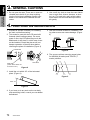
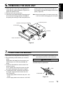
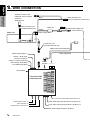
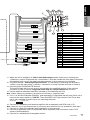
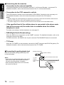
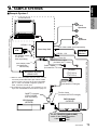
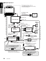
English
VRX928RVD
Installation and Wire connection manual
1.
2.
3.
4.
5.
6.
7.
8.
9.
BEFORE STARTING ...............................................................
PACKAGE CONTENTS ...........................................................
GENERAL CAUTIONS ............................................................
CAUTIONS ON INSTALLATION ..............................................
INSTALLING THE MAIN UNIT .................................................
REMOVING THE MAIN UNIT ..................................................
CAUTIONS ON WIRING ..........................................................
WIRE CONNECTION ..............................................................
SAMPLE SYSTEMS ................................................................
65
65
66
66
67
69
69
70
73
1. BEFORE STARTING
1. This set is exclusively for use in cars with a
negative ground 12 V power supply.
2. Read these instructions carefully.
3. Be sure to disconnect the battery “-” terminal before starting. This is to prevent short
circuits during installation. (Figure 1)
Car battery
Figure 1
2. PACKAGE CONTENTS
1 Main unit
2 Tuner Amp unit
3 Manuals
Owner’s manual & Installation manual
Warranty card
4 Power supply lead (For the main unit)
5 Power supply lead (For the tuner amp
unit)
6 Connection cord (Main unit ↔ Tuner amp unit)
7 Antenna extension cord
8 RGB connecting cord
9 Bag for accessories of the main unit (No. 1)
Flat head screw (M5 × 8) ............................ 4
Sems hexagonal bolt (M5× 8) ..................... 5
Electro tap
Machine screw (M4× 3) ............................... 4
0 Bag for accessories of the main unit (No. 2)
Hook plate ................................................... 2
Cord clamp
Rubber cap
Special screw
! Bag for accessories of tuner amp unit
Maunting bracket ......................................... 2
Canoe clip ................................................... 4
Machine screw (M4 × 8) .............................. 4
@ Universal mounting bracket
# Remote control unit
$ Battery
(for remote control unit)
% Outer Escutcheon
¥ DCP Case
VRX928RVD
71
Installation and Wire
connection manual
■ Contents
English
3. GENERAL CAUTIONS
Installation and Wire
connection manual
1. Do not open the case. There are no user serviceable parts inside. If you drop anything
into the unit during installation, consult your
dealer or an authorized CLARION service
centre.
2. Use a soft, dry cloth to clean the case. Never
use a rough cloth, thinner, benzine, or alcohol, etc. For tough dirt, apply a little cold or
warm water to a soft cloth and wipe off the
dirt gently.
4. CAUTIONS ON INSTALLATION
1. Prepare all articles necessary for installing
the main unit before starting.
2. This model is used with the LCD panel slid
forwards (shell loading system). On some
types of cars, the LCD panel may touch the
dashboard or shift lever, in which case it cannot be installed. Check that the set will not
hamper operation of the shift lever before
choosing the place of installation.(Figure 2)
5. Use the enclosed screws for installation. Using other screws can cause damage. (Figure
4)
Chassis
Chassis
Damage
Max. 8 mm (M5 screw)
Dashboard
Figure 4
6. The source unit has mounting screw holes
for NISSAN (N marks) and TOYOTA (T
marks) vehicles.
T
Shift lever
(check that it does not
touch the LCD.)
N
T
Shift lever
Figure 2
3. Install the unit within 30° of the horizontal
plane. (Figure 3)
N
T
Figure 5
Max. 30˚
Figure 3
4. If you have to do any work on the car body,
such as drilling holes, consult your car dealer
beforehand.
72
VRX928RVD
N
English
5. INSTALLING THE MAIN UNIT
■ Universal Mount
Notes:
1) Some car models require special mounting kits
for proper installation. Consult your Clarion
dealer for details.
2) Fasten the front stopper securely to prevent the
main unit from coming loose.
7-3/16" (182 mm)
Hole
2-1/16" (53 mm)
• Console opening dimensions
Rear fastening hole (of vehicle)
Instrument panel
Hole
Stoppers
Special Screw
Screwdriver
Rubber cap
Main unit
Universal mounting bracket
Stoppers
2-Spring
Outer escutcheon
Note: Set the outer escutcheon so that its metallic
part on the back side
fits the upper edge of
the main unit.
Figure 6
VRX928RVD
73
Installation and Wire
connection manual
1. Place the universal mounting bracket into the
instrument panel, use a screwdriver to bend
each stopper of the universal mounting
bracket inward, then secure the stopper as
shown in Figure 6.
2. Wire as shown in Section 8.
3. Insert the main unit into the universal mounting bracket until it locks.
4. Mount the outer escutcheon so that all the
hooks are locked.
■ Fixed Mount (TOYOTA, NISSAN and other ISO/DIN equipped vehicles)
English
Installation and Wire
connection manual
This unit is designed for fixed installation in the
dashboard.
If the vehicle is equipped with a factory-installed
radio, install the main unit with the parts and
screws marked (∗). (Figure 8)
If the vehicle is not equipped with a factory-installed radio, obtain an installation kit to install
the main unit in the following procedure.
1. Remove the screws from both side of the
main unit. Then, at either side, lift the leaf
spring until the engaging claws are released
from the holes, and slide the spring to the di-
rection of arrow to remove it. Repeat the
same for the other side to remove the
springs from the both sides. (Figure 7)
2. Secure the mounting brackets to the chassis
as shown in Figure 8. Holes are pre-tapped
for TOYOTA and NISSAN vehicles; modification, such as drilling new holes, of the mounting brackets may be required for other models.
3. Wire as shown in Section 8.
4. Secure the unit in the dashboard, and then
reassemble the dashboard and the centre
panel.
2-Screw
Engagin claw
Main Unit
2-Spring
Screwdriver
Figure 7
4-Hexagonal screw ∗ (M5 × 8)
Mounting bracket
(1 pair for the left and right sides)
Main Unit
Pocket
Note 2
Centre Panel (Note 1)
∗: The screws with this mark are
enclosed in this set.
★: The parts and screws with this mark
are used to install radio or included in
the installation kit.
Figure 8
Note 1: In some cases, the centre panel may require
some modification (trimming, filling, etc.).
74
VRX928RVD
Note 2: If a hook on the installation bracket interferes with the unit, bend and flatten it with
a nipper or a similar tool.
pull the main unit out by the hook plate. (Insert both the right and left edges of the hook
plate.) (Figure 9)
Note: Keep the hook plate. You cannot remove the
main unit without disengaging the hook plate.
Instrument panel
Universal mounting bracket
2-Hook plate
Main
Unit
Spring
Outer escutcheon
A
B
Figure 9
7. CAUTIONS ON WIRING
1. Be sure to turn the power off before wiring.
2. Be particularly careful where you route the
wires.
Keep them well away from the engine, and
exhaust pipe, etc. Heat may damage the
wires.
3. If the fuse should blow, check to see if the
wiring is correct.
If it is, replace the fuse with a new one with
the same amperage rating as the original.
4. To replace the fuse, remove the old fuse of
the power supply lead and insert the new
one. (Figure10)
∗ Power supply lead for the tuner amp unit : 15A
FUSE
∗ Power supply lead for the main unit : 3A FUSE
Note: There are various types of fuse holder. Do not
let the battery side touch other metal parts.
CAUTION
After the connection, fix the lead by a clamp or
insulation tape for protection.
Fuse
Fuse holder
Figure 10
VRX928RVD
75
Installation and Wire
connection manual
1. When the rear of the main unit has been secured with the method shown in Figure 6 unfasten the special screw.
2. Remove the outer escutcheon.
3. Insert the hook plate between the spring and
the universal mounting bracket, fit tab B of
the spring into hole A of the hook plate, then
English
6. REMOVING THE MAIN UNIT
English
8. WIRE CONNECTION
Installation and Wire
connection manual
Securely connect to the
metal part of the car with a
screw, etc.
Black
Earth (Ground) cord
RGB terminal
RGB connecting cord
(provided with this unit)
Yellow
Choke coil
Power supply lead
Main unit
Main power supply cord
Fuse
Connection cord
(provided with this unit)
CeNET cable (Sold separately)
VIDEO output (RCA) ∗7
Power supply lead
VISUAL 1 audio input
terminal L+R (RCA)
VISUAL 1 video input (RCA)/
DVD changer input (RCA)
CeNET
terminal
TV TUNER input (RCA)
Reset switch
Top view of the
tuner amp unit
5.1 ch Surround Decoder select switch ∗5
Radio antenna jack ∗4
NAVI terminal ∗9
CCD/VISUAL 2 terminal ∗8
Rear audio output (input) terminal L+R (RCA) ∗6
Front audio output (input) terminal L+R (RCA) ∗6
Non Fader output terminal L+R (RCA)
76
VRX928RVD
B-3
B-5
B-4
B-1
English
B-2
B-6
4
Installation and Wire
connection manual
B-7
B-8
A-7
∗2
A-8
∗2
2
A-6
A-1
A-4
5
∗2
∗2
3
1
No.
B-1
B-2
B-3
B-4
B-5
B-6
B-7
B-8
A-1
A-4
A-5
A-6
A-7
A-8
1
2
3
4
5
A-5
Description
REAR RIGHT+
REAR RIGHTFRONT RIGHT+
FRONT RIGHTFRONT LEFT+
FRONT LEFTREAR LEFT+
REAR LEFTSPEED PULSE
+12 V MAIN POWER (∗2)
AUTO ANTENNA (∗1)
ILLUMINATION
+12 V ACCESSORY (∗2)
GROUND
Spare terminal (Black)
Phone terminal (Brown) (∗3)
Spare terminal (Yellow)
ISO CONNECTOR
Parking brake (Bright Green)
∗1: When the unit is installed in a 1998 or later Volkswagen model, make sure to interrupt the
<<Remote>> output. Disconnect the <<blue/white>> wire and insulate the front ends of this lead.
A breakdown may occur if the lead is not disconnected, or front ends are not insulated.
∗2: In certain vehicles - Volkswagen/Opel/Vauxhall - it is necessary to exchange the accessory
<<Red>> and the main power <<Yellow>> connection, to avoid overload and loss of memory.
∗3: Connecting the PHONE MUTE Terminal
The lead included with the unit must be connected to the specified position of the vehicle’s
connector in order to use the “triggered audio mute for cellular telephones” function.
∗4: Use the attached extension lead when necessary. (Provided with this unit)
Note : Before making any installation, disconnect the car battery - (negative) cable.
∗5: If a 5.1 ch Surround Decoder (DVH923, sold separately) is connected and the amp of this unit is
used, set the select switch to “LINE IN”. Then the AUDIO OUT (IN) terminal of the Tuner Amp
Unit is only available for audio input, not outputting the audio.
(LINE IN) D
N (LINE OUT)
∗6: Connect to a separately sold external amplifier with a separately sold RCA cord (L, R).
Note : When the 5.1 ch Surround Decoder is connected, these terminals are only available for audio input.
∗7: Connect to a Rear View Monitor (sold separately) for the rear seat.
∗8: Connect to separately sold VTR equipment with a separately sold connection cord or CCD
camera (Sold separately).
∗9: Connect to a separately sold navigation device.
VRX928RVD
77
English
■ Connecting the Accessories
• Connection to the external amplifier
The external amplifier can be connected unless the 5.1 ch Surround Decoder is connected. For
detailed information, refer to the instruction manual of the 5.1 ch Surround Decoder.
Installation and Wire
connection manual
• Connection to the CCD camera for vehicle
The CCD camera for vehicle can be connected to CCD/VISUAL 2 terminal on the tuner amp unit.
For detailed information, refer to the instruction sheet or manual for the CCD camera.
Notes:
• A power supply box (sold separately) is required for connection of the main unit and the CCD camera.
• While the CCD camera is used, the navigation cannot be turned on.
• The power supply box for camera CAA147 cannot be used. Please use the CAA188 instead.
• If the specified lead of the cellular phone is connected to the phone mute
lead of the source unit, the audio mute is available when the cellular
telephone is used.
For audio mute setting in cellular telephone use, see page 63.
• DAB (Digital Audio Broadcasting)
When the DAB is to be connected, use the CeNET connector. For detailed information, refer to the
instruction manual of the DAB.
For DAB connection, the DAH913 can only be connected. The DAH9500Z cannot be connected.
• TV Tunner
When the TV TUNER is to be connected, connect the CeNET connector and RCA PIN (yellow). For
detailed information, refer to the instruction manual of the TV TUNER.
■ Connecting the parking brake lead
Parking brake lamp
+ lead to battery
Connect the lead to parking brake lamp earth
in the meter panel.
Notes:
• Connecting the parking brake lead to lamp earth
allows you to watch TV/VTR/DVD video/video
CD when the parking brake is engaged.
• When the parking brake lead is not connected,
the monitor will stay off.
- cord
parking
brake signal
lead
Connect these three leads.
Parking brake lead
(bright green)
Parking brake
78
VRX928RVD
English
9. SAMPLE SYSTEMS
■ Sample System 1
Installation and Wire
connection manual
VRX928RVD
Front
Speakers
VISUAL 2 IN
Tuner Amp Unit
RCA video cable (sold separately)
VTR
Rear View
Monitor
VISUAL 1 IN
AV Adapter cable
(CCA-389,
sold separately)
Tuner IN
RCA video cable
(included the TV tuner)
Mini DIN(8P) Cable*1
(included the
NAX9500E)
CeNET cable
(included the TV tuner)
TV tuner
Navigation System
(NAX9500E)
(TTX7502z/
TTX7503z)
*1.When a video composite source is used, connect
it to the 8-pin Mini-DIN video jack. When a RGB
source is used, connect it to the 8-pin DIN RGB
jack. In case a CLARION navigation system is
used, connect it to both input.
*2.To enable the correct input, it is necessary to configure the VRX928RVD as described on page 59.
CeNET Y-adapter
(CCA-519-500,
sold separately)
CeNET Cable
(included the Changer)
RCA video cable (included the VCZ628)
RGB cable*1 (included the NAX9500E)
Rear
Speakers
Ferrite clamp
(Included the DVD changer)
DVD Changer
(VCZ628)
CD Changer
(DCZ628)
Set the [CENET/STAND ALONE]
switch to the [CeNET] position.
CeNET
STAND
ALONE
VRX928RVD
79
■ Sample System 2
English
∗ The diagram shows a 5.1 ch
surround system configuration using
an external amplifier.
VRX925VD
Installation and Wire
connection manual
AV Adapter cable
(CCA-389,
sold separately)
(Glay)
VTR
Tuner Amp Unit
VISUAL 1 IN
Front
Speakers
Tuner IN
RCA video cable
(included the TV tuner)
RCA cable
(sold separately)
CeNET
cable
(included
the TV
tuner)
CeNET
TV Tuner
4-Channel
Amplifier
Rear
Speakers
RCA cable
(included the SRK601)
CeNET cable
(included the
DVH923)
,,,,,,
,,,,,,
,,,,,, Center speaker
,,,,,,
,,,,,,
built-in amplifier
(SRK601)
(Black)
5.1 ch Surround
Decoder(DVH923)
Powered sub-woofer
built-in amplifier
RCA cable (sold separately)
CeNET cable
(included the VCZ628)
Ferrite clamp
(Included the DVD changer)
CeNET DVD Changer
(VCZ628)
Set the [SLAVE/STAND ALONE]
switch to the [SLAVE] position.
SLAVE
STAND
ALONE
Digital optical fiber cable
(DCA-005/008, sold separately)
(Glay)
Set the [CENET/STAND ALONE]
switch to the [CeNET] position.
CeNET
80
VRX928RVD
STAND
ALONE
RCA video cable (included the VCZ628)
Digital optical fiber cable (included the DVH923)
VISUAL 2 IN
■ Sample System 3
English
A 5.1 ch surround system configuration is made using the built-in amplifier of the Tuner Amp Unit.
The diagram below shows the different part from Sample system 2.
Installation and Wire
connection manual
Set the [(LINE IN)D/N(LINE OUT)]
switch to the [(LINE IN)D] position.
(LINE IN)D
N(LINE OUT)
Front
Speakers
Tuner Amp Unit
Rear
Speakers
RCA cable
(sold separately)
RCA cable
(inclouded the SRK601)
(Black)
5.1 ch Surround
Decoder(DVH923)
,,,,,,
,,,,,,
,,,,,, Center speaker
,,,,,,
,,,,,, built-in amplifier
(SRK601)
Powered sub-woofer
built-in amplifier
RCA cable (sold separately)
VRX928RVD
81
82
VRX928RVD