1
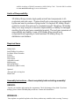
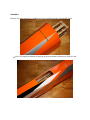
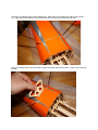
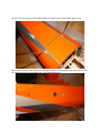
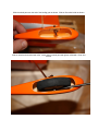
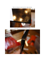
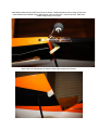
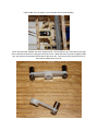
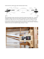
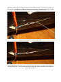
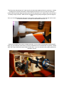
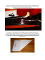
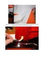
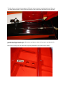
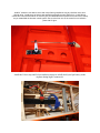
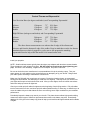
Assembly Manual / Airframe – 48” Edge 540
Thank you for purchasing this 3DHobbyShop ARF RC aircraft. If you have any issues,
questions, concerns or problems during assembly, please contact our tech department at:
[email protected] or 717-814-5316 10am-4pm Eastern Monday thru Thursday.
SAFETY in Assembly
During assembly of this aircraft, you will be asked to use sharp knives and hobby adhesives.
Please follow all safety procedures recommended by the manufacturers of the products you use,
and always follow these important guidelines:
ALWAYS protect your eyes when working with adhesives, knives, or tools, especially power tools.
Safety glasses are the best way to protect your eyes.
• ALWAYS protect your body, especially your hands and fingers when using adhesives,
knives, or tools, especially power tools. Do not cut toward exposed skin with hobby
knives. Do not place hobby knives on tables or benches where they can roll off or be
knocked off.
• ALWAYS have a first-aid kit handy when working with adhesives, knives, or tools,
especially power tools.
• ALWAYS keep hobby equipment and supplies out of the reach of children.
SAFETY in Flying
This is NOT a toy! It is a very high-performance RC airplane capable of high speeds and
extreme maneuvers. It should only be operated by a competent pilot in a safe area with proper
supervision.
• ONLY fly your aircraft in a safe, open area, away from spectators and vehicles and
where it is legal to fly. NEVER fly over an unsafe area, such as a road or street.
• NEVER fly near overhead power or utility lines. If your airplane ever becomes stuck in
a line or a tree DO NOT attempt to retrieve it yourself. Contact the authorities for
assistance in retrieving your aircraft. Power lines are DANGEROUS and falls from
ladders and trees CAN KILL!
• Never fly too close to yourself or spectators.
• Spinning propellers are DANGEROUS!
Never run your motor inside a house or building with the propeller attached Remove the
prop for safety. Always fly within your control.
• Always follow manufacturers instructions for your radio system.
• Always preform a pre-flight check of your aircraft to be certain of the aircraft's
airworthiness.
• Always obtain proper insurance before flying. Always fly model aircraft in accordance
with the Academy of Model Aeronautics (AMA) Safety Code. Visit the AMA's website
at www.modelaircraft.org for more information.
Limits of Responsibility
3D Hobby Shop provides high-quality aircraft and components to it's
customers and end users. These aircraft and components are assembled
by the end user to produce a flying model. It is beyond 3D Hobby Shop's
control to monitor the end user's completed aircraft. Therefore, 3D Hobby
Shop in no way accepts or assumes responsibility or liability for damages
resulting from the end user assembled product. The end user assumes all
responsibility and liability in use of 3D Hobby Shop aircraft and
components and agreeing to hold harmless 3D Hobby Shop, it's
distributors and dealers.
Required Items
Hobby Knife
Small Phillips Screwdriver
Set Metric Allen Wrenches
Scissors
Small Pliers
Wire Cutters
Adjustable wrench
Masking tape
Drill and drill bits
Threadlocker (Blue Loctite)
Optional:
Heat gun and covering iron
Dremel tool
Assembly Instructions – Read completely before starting assembly!
UNPACK :
Unpack your airplane and examine the components. Check for damage of any kind. If you have
damage, please contact 3DHobbyShop to discuss. Contact info listed above.
WRINKLES :
Your airplane was packed in plastic at the factory without any wrinkles in the covering. You may
notice some wrinkles now; more likely, you will notice a few in a day or two or the first time you take
the plane out to the flying field. These wrinkles are the result of wood shrinkage and/or expansion.
Balsa wood changes size and shape slightly as it is exposed to varying humidity in the air. This is a
natural property of balsa wood. As your airplane adjusts to the weather in your part of the world,
wrinkles may appear and disappear. Wrinkles may be removed with the gentle application of heat to
the covering material on your airplane. The best tools to use are a heat gun and covering iron. Apply
the heat gently: the covering material will shrink as you apply the heat, and this will remove the
wrinkles. BE CAREFUL! Too much heat applied too quickly can damage the covering, either by
causing it to pull away from the wood at seams and corners or even by melting it. The covering will
shrink at low temperature with patient application of heat. Wrinkles in the covering DO NOT affect
flight performance. If you must shrink on a color-seam, use the iron and go slowly and carefully to
avoid any pulling or lifting at the seam.
Remove the canopy before attempting to use heat on your covering! The canopy is made of thermoactivated plastic and WILL deform with the application of heat. Do not apply heat to the canopy.
PAINT:
If you need to clean your airplane, we recommend using a damp towel. The paint used on the canopy
and cowl is not safe for all cleaners. In particular, DO NOT use alcohol on these parts, it will remove
the paint.
Let’s get started!
ASSEMBLY
Remove covering material over landing gear slot as indicated with a sharp hobby knife.
Remove covering from bottom of fuselage in the area shown to function as a hot-air vent.
Trial-fit the wire landing gear into the fuselage slot. Make sure you can easily put it all the way into the
slot. Apply a generous amount of 30-minute epoxy into the slot and install the landing gear.
Apply more epoxy into the slot and install the gear brace plywood piece as shown. Slide it all the way into
the slot.
Clean up any excess epoxy using rubbing alcohol on a paper towel. All the landing gear to cure.
Remove the covering on both sides of the fuselage as shown, for the wing spar tube, aileron wire access,
wing retaining screw, and anti-rotation pin. Use a sharp hobby knife.
Make sure your hobby knife blade is very sharp, and remove the covering over the horizontal stabilizer
opening in each side of the fuselage as shown.
Slide the wheel pant over the end of the landing gear as shown. Slide on first wheel collar as shown.
Slide on wheel and second wheel collar, center wheel in wheel pant and tighten collars with 1.5mm hex
wrench.
Use two of the included wood screws to install the nylon plastic gear strap onto the wheel pant as shown.
Apply some 30 minute epoxy between the strap and the pant before tightening the screws. Take your
time with this step, make sure the wood screws are penetrating into the plywood piece inside the pant.
Locate the gear leg fairing. Remove the covering over the groove in the fairing as shown.
Apply a generous amount of 30 minute epoxy into the groove and install the fairing as shown.
Allow all epoxy to cure.
Remove covering over control horn slot in rudder as shown.
Install rudder horn into slot with CA glue as shown.
Remove covering over tail wheel wire slot in bottom of rudder as shown and test-fit tailwheel wire. When
satisfied with fit, apply 30-minute epoxy into slot, install wire, and allow to cure.
Install rudder onto fuselage, align with fuselage, and when satisfied with alignment, apply 2 drops of thin
CA onto each hinge as shown.
Install tailwheel bracket using ONE wood screw as shown. Bracket should be able to swing left and right.
Install tailwheel and tailwheel collar, tightening set screw in collar with 1.5mm hex wrench. Make sure
rudder swings easily left and right.
Apply a piece of masking tape as shown to hold rudder straight and centered.
Install rudder servo as shown, in the orientation shown inside fuselage.
Servo connectors are installed onto servo arms as shown. Drill the holes in your servo arms to the right
size to allow the connectors to easily spin on the servo arm. Attach with the nut, but do not tighten all the
way, the connector must remain able to twist on the servo arm. Lock the nut with a drop of thick CA so
that it cannot vibrate loose in the air.
Please examine the rudder pull-pull system assembly diagram closely:
Start by attaching the cables to the pull-wire end at the front, where they will attach to the . Crimp well,
preferably by making creases in the crimp tube with a sharp pliers or cutters, rather than smashing it
completely flat. Apply a drop of thin ca to the completed crimp to prevent it from sliding on the cable.
Insert the pull-wire ends into the servo connectors on the rudder servo as shown, just barely poking
through the servo connectors, and tighten down the set screws with a 1.5mm hex wrench. Note that the
cables cross each other once inside the fuselage, making an “X” shape.
Assemble the rear ends of the rudder pull cables onto the rudder as shown. Use thick CA to lock the nut
on the bottom of the rudder horn. Make sure there is not much slack in the cable, look inside the fuselage
to make sure the cables have no kinks in them and are routed correctly.
Crimp the cables and trim the excess cable length.
Use the adjustment on the rudder servo connectors to take up any slack in the cables, make them snug
not “banjo string” tight. Just snug without any slack is all we need. Remove the tape on the rudder and
check rudder operation.
Locate the carbon wing spar tube and insert it into the fuselage. The carbon tube is NOT to be glued in, it
is to remain removable. Insert the horizontal stabilizer into the fuselage as shown. Measure from the
tube to the stabilizer on both sides of the fuselage as shown to make sure the stabilizer is straight.
Measure the stabilizer side-to-side to make sure it is centered.
Apply thin CA glue to the joint of the horizontal stabilizer and fuselage. Allow the thin CA to wick into the
joint. NOTE: It is not necessary to remove any covering on the stabilizer.
Install the elevator half with the joiner rod attached WITHOUT glue and make sure it can swing easily 45
degrees up and 45 degrees down. You will have a small gap in the hingeline. NOTE – Measuring 45
degrees is demonstrated later in this manual in the section on the elevator servo Apply two large drops
of thin CA to the hinges to permanently install the elevator.
Place a piece of tape between the elevator and stabilizer to hold the elevator straight and level to the
stabilizer.
Trial fit the other side elevator half, make sure the elevators are straight and level to each other. A slight
misalignment of elevator halves will not affect flight performance, but you can make sure that your
elevators will be perfectly aligned by taking a bit of time to align them now. Sand the slot in the elevator if
necessary to align elevators. Make sure the elevators can swing easily 45 degrees up and 45 degrees
down.
Once you are satisfied with the alignment of the elevators, apply medium or thick CA glue into the slot in
the elevator as shown, and install onto the stabilizer with thin CA.
Install your brushless motor onto the firewall as shown. If you use the recommended Omega130g870
motor, you can install the motor directly onto the pre-installed nuts in the firewall with no spacers. Hacker
A30L and Torque 2814-820 motors install the same way. If you use a shorter motor, plastic spacers are
included in your kit.
Install ESC onto the side of the motor box with zip ties as shown.
The cowl is mounted onto the fuselage with 4 wood screws. These screws go into the small plywood
squares on the front inside of the fuselage. Place small strips of tape over the squares as shown. Install
the canopy hatch.
Install the cowl, line up with front of motor. Use the strips of tape as guides to know exactly where to drill
the holes in the cowl to install the wood screws.
Remove covering over the elevator servo opening as shown.
Attach a 12” Extension onto the elevator servo and install the servo as shown. Assemble the longest
pushrod in your kit with the ball link and control horn as shown. Use thick CA to lock the nut on the
control horn. DO NOT GLUE INTO THE ELEVATOR YET.
On 3D planes, it is very important to have 45 degrees of elevator throw on high-rates setting. We
recommend that you check to make sure you have 45 degrees of throw up and down, by inserting the
horn into the elevator WITHOUT GLUE and hooking up your pushrod and servo and operating your radio.
Turn the endpoint adjustment up on your transmitter to maximum, and check the amount of elevator
throw you have. If you need help measuring 45 degrees, fold a piece of paper as shown and use it to
measure the throw.
If you don’t have enough throw, you can choose to either install a longer arm on your servo, or you can
reduce the height of your elevator horn by trimming it as shown.
This will allow you to insert the arm approx 1/8” farther into the elevator, increasing the throw. When you
are ready, apply medium or thick CA glue generously to the elevator horn and insert it into the elevator.
Assemble the ailerons onto the wings, flex them up and down to check for free motion, and drip thin CA
glue onto each hinge. Allow to dry.
Remove the covering over the aileron servo openings and aileron control horn slots as shown.
Install 6” extension onto aileron servo and use pull-string installed in wing to pull aileron servo wire
through wing. Install servo as shown, and assemble pushrod/horn onto aileron horn. Install aileron
control horn into slot with medium or thick CA glue and assemble aileron pushrod onto servo arm, exactly
as you assembled the elevator control system. Be sure the 2mm nut on the control horn is locked in
place with CA glue.
Install the Velcro strip and Velcro seatbelt as shown to solidly hold your lipo battery in the
airplane during high-G maneuvers.
If desired, you can mount your receiver on the balsa receiver plate (marked Rx) and glue the plate into
the bottom of the fuselage as shown.
Plug your servos and ESC into your receiver, attach your battery and test your radio system. Check for
correct motor running direction now, before your prop is installed. Never run your motor inside a
building with the prop installed. Check for correct servo direction, reverse as necessary. Center all
control surfaces and tighten pushrod adjusters securely.
Balancing:
Balance your Edge at a point 80mm-90mm behind the leading edge of the wing where the wing meets the
fuselage. 80mm is a sport flying CG, 90mm is a 3D flying CG.
Control Throws and Exponential
Low/Precision Rates (in degrees and inches) and Corresponding Exponential
Aileron
Elevator
Rudder
15 degrees
13 degrees
45 degrees
.75” 30% Expo
1.25” 30% Expo
3.5” 75% Expo
High/3D Rates (in degrees and inches) and Corresponding Exponential
Aileron
Elevator
Rudder
28 degrees
45 degrees
45 degrees
1.25” 75% Expo
3”
75% Expo
3.5” 75% Expo
The above throw measurements were taken at the aft edge of the ailerons and
elevator, and from the bottom aft edge of the rudder. Keep in mind that even the low throws
mentioned here are relatively aggressive, so be sure to also program the matching
exponential listed to help soften the model’s feel around center stick.
Install your propeller.
NOTE: Small brushless motors typically have aluminum prop adaptors with aluminum screws threads.
These threads are easily stripped or broken. DO NOT apply too much torque when tightening your
prop. A wrench is not necessary, it applies too much torque. We prefer a nut-driver.
Be sure to check the motor manufacturer’s recommendations for help in selecting a prop. Test your
power system in a safe manner on the ground before ever attempting to fly your aircraft. Range check
your radio system according to manufacturer’s instructions.
Make your first flight with the controls set on low rates. During the trimming phase, we recommend
landing with some throttle, not attempting to “dead stick” the airplane. This may mean you need to time
your flights and keep them a bit shorter than usual. After your first flights, check all control connections
and motor and prop mounts for tightness.
Check your rudder pull-pull cables for tightness at the beginning of each flying session. Pull-pull cables
tend to loosen a bit over time, and loose pull-pull cables (cables that flop, or have sag, or that allow you to
move the rudder with your hand without the servo arm moving) are a major contributor to poor aerobatic
performance.
Periodically inspect the battery tray area in your aircraft. This plane does excellent high-speed tumbling
maneuvers, and this type of maneuver puts tremendous stress on the battery tray area. Occasionally
adding a bit of CA glue to the battery tray joints will help your aircraft last through hundreds and hundreds
of flights.
We hope you enjoy your 3D HOBBY SHOP Aircraft.
Be sure to look for new aircraft and products coming soon from
3D HOBBYSHOP.COM
Copyright 2014 3D Hobby Shop