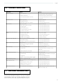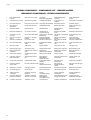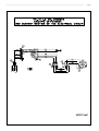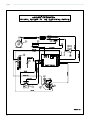
1
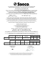
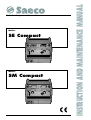
Models: SE Compact Models: SM Compact INSTRUCTION AND MAINTENANCE MANUAL Professional espresso coffee machine English We thank you for your custom in the purchase of this product. By carefully following the instructions contained in this manual you will be sure to appreciate the quality of our machine. Please therefore carefully read the instructions of use contained in this manual, which comply with essential safety regulations. Carefully read the following instruction booklet before starting up the machine. Carefully read the following instruction booklet before starting up the machine. Important ! Hot surfaces. Important! Particularly important and/or delicate operations Important ! Operations essential to guarantee efficient function Operations which may be carried out by the user Operations to be undertaken solely by an installer or authorized technician. 2 English DICHIARAZIONE DI CONFORMITA’ CE – DECLARATION DE CONFORMITE CE EG-KONFORMITÄTSERKLÄRUNG – EC DECLARATION OF CONFORMITY DECLARACIÓ DE CONFORMIDAD CE La Ditta Saeco International Group S.p.a. Dichiara sotto la propria responsabilità chi i prodotti: Macchina per caffè per uso professionale Déclare que les produits suivants: Machines à café expresso pour usage professionnel Erklärt, dass die folgenden Produkte: Gewerbe Espresso Kaffeemaschinen Declare that the following product: Espresso coffe machines for professional use Declara bajo nuestra responsabilidad que el producto: Máquina para café de uso profesional Modelli – Modèles Modelle – Models – Modelo SE – SM Compact 1–2 gr al quale è riferita questa Dichiarazione, secondo quanto prescritto dalle direttive specifiche: à laquelle se réfère cette dèclaration, selon les prescriptions des directives specifiques: auf das sich diese Erklärung bezieht, Entsprechend der Vorschriften der spezifischen Richtlinien: to which this declaration relates is, according to the provisions of the specific directives: al cual se refiere esta Declaración, de acuerdo con lo prescrito por las especificas directivas: 98/37/CE;73/23/CE, 93/68/CE;89/336/CE, 93/68/CE, 92/31/CE;97/23/CE è conforme alle seguenti norme: conforme aux normes suivantes: in Übereinstimmung mit den folgenden Normen: It complies with the following norms: es conforme a las sigientes normas: EN 292-1; EN292-2; EN 60335-1; IEC 335-2-75 + A1: 98 EN 55014-1: 1993 + A1: 1997; EN55014-2:1997 EN61000-3-2: 1995 + A13: 1997 EN 61000-3-3:1995 Raccolta M ed.78; Raccolta S Ed.78; Raccolta E; Art. 15 D.M. 21.5.74; Raccolta VRS Ed.72 Descrizione attrezzatura a pressione – Decription de l’appareillage sous pression - Beschreibung der unter Druck stehenden Geräte – Pressure device description – Descripción de los equipos de presión Pressione Max. pa/bar Pressin – Druck Pressure - Presión Caldaia Chaudière – Kessel Boiler - Caldera Temp. Max °C Température – Temperatur Temperature - Temperatura Fluido Fluide – Flüssig Fluid – Fluido 131 Acqua / Vapore Eau / Vapeur – Wasser / Dampf Water / Steam – Agua / Vapor 0,18/1,8 Pressione Max. pa/bar Pressin – Druck Pressure - Presión Scambiatore Echangeur-Austauscher Exchanger - Intercambiador Temp. Max °C Température-Temperatur Temperature-Temperatura Fluido Fluide – Flüssig Fluid - Fluido Capacità it Capacité-Fähigkeit Capacity - Potencia 131 Acqua Eau-Wasser Water-Agua 0,280 0,11/11 Gaggio Montano 15/05/2003 Capacità it – Capacité – Fähigkeit it – Capacity it – Potencia it 1 gr 2 gr 4,9 4,9 Numero scambiatore – Numéro de l’échangeur Nummer des Austauschers – Exehanger number Número intercambiador 1 gr 2 gr 1 2 Presidente Giovanni Zaccanti 03 La presente dichiarazione perde la sua validità se la macchina viene modificata senza la nostra espressa autorizzazione. La Présente déclaration perd sa validité dés lors que la machine est modifiée sans notre expresse autorisation. Die vorliegende Erklärung verliert ihre Gültigkeit, wenn die Maschine ohne unsere ausdrückliche Genehmigung verändert wird. The present declaration will become invalid should the machine be modified without our specific authorization. La presente declaraciòn pierde su validez si la máquina es modificada sin nuestra expresa autorización. 3 English 4 English INDICE INDICE. ................................................................................................................ 5 1- INSTRUCTIONS BOOKLET CONSERVATION AND USE. ............................................................................................. 6 2- ENVISAGED MACHINE USE. ............................................ 6 3 - SAFETY ADVICE. ............................................................................ 7 4 - TECHNICAL FEATURES. ........................................................... 8 5 - INSTALLATION. .............................................................................. 9 5.1 Water connection. ........................................................ 9 5.2 Electrical connection. ................................................... 9 6 - START 6.1 6.2 6.3 6.4 6.5 UP. ............................................................................................ 10 Long coffee gigleuri. .................................................... 10 Pressure switch adjustment. ...................................... 11 Pump pressure calibration. ....................................... 11 Filters for coffee machine. ......................................... 11 Replacement of the thermostat to reduce the coffee dispensing group temperature. ........ 12 7 - FUNCTION / USE AND PROGRAMMING. ........ 12 7.1 Coffee measure programming. .............................. 13 7.2 Coffee delivery. .............................................................. 14 7.3 Continuous coffee measures. .................................. 15 7.4 Special functions. ........................................................... 15 7.5 Alarm condition. ............................................................. 16 8 - PURIFIER REGENERATION. ................................................ 17 9 - MAINTENANCE AND USEFUL ADVICE. ................... 18 10 -TROUBLE SHOOTING. ............................................................ 19 11 -MACHINE DISMANTLING. ................................................. 19 5 English 1 - INSTRUCTIONS BOOKLET CONSERVATION 2 - ENVISAGED MACHINE USE The present instructions booklet has been prepared for the machine user, the owner and the installation technician and must be always available for reference purposes. The machine must be operated by a single operator only. The manual is destined for the user, the maintenance technician and machine installation technician. The purpose of the instructions booklet is to indicate the envisaged uses of the machine for which it has been designed, its technical features and in order to provide advice on correct use, cleaning and regulation. It also provides important maintenance information, and details on any residual risks, and all those operations which require particular care. The present manual is to be considered as an integral part of the machine and must be CONSERVED FOR FUTURE REFERENCE until the final dismantling of the machine. This instructions booklet must always be available for consultation and must be kept in a protected and dry place. In the event of loss or damage to the same, the user may ask the manufacturer or local dealer for a new manual, indicating the machine model and serial number of the same as indicated on the identification plate. The present manual reflects the state of the art, at the time of its preparation, the manufacturer however reserves the right to revise production and subsequent manuals without being obliged to update previous versions. The manufacturer declines all responsibility in the event of : - the improper or incorrect use of the coffee machine - use that fails to comply with that specifically stated in the present booklet - serious lack of maintenance as envisaged or recommended - machine modifications or any non-authorized intervention - use of either non-original or non-specific spares - total or partial failure to observe the instructions 6 The authorized operator must have firstly read and fully understood all the instructions contained in the present booklet to ensure correct machine function. This machine is specifically intended for the professional preparation of espresso coffee using blended coffee, as well as the drawing and delivery of water and/or steam. Its components are made of resilient non toxic materials, and they are easily accessible for cleaning or maintenance operations. This machine is intended for internal use only. Ambient temperature for the correct operation of the machine 5°C ÷ 40°C. English 3 - SAFETY ADVICE The machine is to be used solely by adults who have carefully read and fully understood this manual and all the safety advice contained in the same. The user is responsible in relation to third parties in the working area. The installer, user and maintenance technician are obliged to notify the constructor of any defects or faults which may effect the original safety of the system. on the machine, or in the event of the use of non-original spares all guarantee terms become void, and the company reserves the right to reject validity. The user must comply with the current safety laws in force in the country of installation, as well as common sense and ensure that all maintenance operations are regularly carried out. Never clean the inside of the machine with power supply on and plug connected and in any event avoid the use of water sprays or detergents. The user must not touch the machine if his hands or feet are wet or damp, neither must be use the machine in bare feet. Although the machine is earthed it is advisable to use wooden platforms or a cut-out box complying with local laws in order to prevent the risk of electrocution. Installation must be effected solely by authorized and qualified personnel. The machine is to be used solely in the presence of suitable lighting. For safety reasons, all worn or damaged parts must be promptly replaced. Regularly check that the power supply cable is in good conditions. Damaged cables must never be repaired using insulating tape or clamps. Do not expose the machine to the elements (sun, rain , etc). Prolonged machine standstill at temperatures of under 0°C (zero degrees centigrade), may cause serious damage or breakage to the boiler piping: it is therefore necessary to completely empty the water circuit before every prolonged standstill. The removal of guard and/or safety elements fitted on the machine is forbidden. The packaging components must be consigned to special disposal centres and must in any event never be left unguarded or within reach of children, animals or nonauthorized persons. The constructor declines responsibility for any damage to things, persons or animals caused by eventual interventions on the machine by personnel not specifically authorized to undertake such operations. In the event of any non-authorized interventions or repairs 7 English H 4 - TECHNICAL FEATURES L B fig. 1 1 group 2 groups B 420 570 H 530 530 L 540 540 kg 37 43 L 4,9 4,9 230 / 240 V ~ W 3200 3200 120 V ~ W 3200 3200 Dimensions Weight Boiler capacity Boiler resistance absorbed power 8 English 5 - 5.1 Water connection INSTALLATION Important: The machine must be supplied with water of over 8°F hardness. E The installation of a water softener is recommended for the machine water supply. Check that the water mains to which connection is to be made supplies drinking water. - NB: before connecting the purifier to the machine, wash out thoroughly until the water becomes clear, then proceed to connect the purifier to the machine. C D F A B - Connect the drain cup (E) to the drainage pipe (B) - Should the mains pressure be higher than 5 bar a pressure reducer balanced for high pressure should be installed (device in which any mains pressure increase does not effect the output pressure). 5.2 Electrical connection fig. 2 A B C D E F Connect purifier (D) to the water mains (A). MAINS SUPPLY DISCHARGE DUCTS PROTECTION SWITCH PURIFIER DRIP BOWL POWER CABLE Before proceeding with installation check that: 1 there are no bumps, signs of knocks or deformities. 2 there are no damp patches or marks which could lead one to assume that the packaging has been exposed to the elements 3 there are no signs of tampering Once one is satisfied that transportation has been correctly effected proceed with installation. Proceed with installation following the instructions according to the sequence as described below. N.B. The least height of the support's top must be 110cm. Important ! Before proceeding with electrical connection it is necessary to check to ensure that the voltage rating corresponds with that indicated on the CE plate and on the connection plate on the power supply cable. Check to ensure that the electrical supply line is able to support the machine load (see chap. 4 technical features table). Connect to an earthing socket which complies with current legislation. Check that the power supply cable is efficient and that it complies with national and European safety standards. The user must undertake to power the machine protecting the power line using a suitable safety switch (cut-out) that complies with the legislation in force in the actual country itself. Connect the power cable (F) to the electric line using a plug, or in the case of fixed installation, using a multi-polar switch (C) for mains separation, with a contact distance of at least 3 mm. For voltage change refer to the diagram shown on the general mains switch box. The yellow-green coloured cable MUST be connected to the rooms earthing system. 9 English Once the water and electrical connections have been made, proceed to start up the machine. 6 - START UP Open the mains water supply tap (A) (fig 2). Close the protection switch (C) (fig 2). 15 mod. SE 10 11 12 13 14 mod. SM Position the machine main switch (9) to position the machine on indicator will come on (7). The auto-levelling device will come into operation so that the water reaches a normal level in the boiler (5). Position the main switch (9) to position for operation at normal power or to position for operation at full power, thereby powering the resistances. Wait for the pressure to reach its operational pressure 1.1÷1.3 atm checking the boiler pressure on the gauge (6). 1 3 4 5 15 3 2 Should the machine fail to stabilize on the indicated values it is necessary to calibrate the pressure switch as described in paragraph 6.2. Then check the pressure on the pump gauge (6) putting a unit into operation with filter holder engaged filled with ground, dosed and pressed coffee in order to achieve an effective working pressure of 8/9 atm. Should re-calibration of the pump pressure be necessary this operation should be undertaken as indicated in paragraph 6.3. The machine is now ready for use. 9 6 6.1 Long coffee gigleur 8 7 7 9 fig. 3 1 2 3 4 5 6 7 8 9 10 11 12 13 14 15 10 Steam tap Steam dispenser nozzle Hot water tap Hot water dispenser Boiler level indicator Two boilers/pump manometer Coffee maker ON LED Cup warmer ON/OFF switch Power ON/OFF switch Selection: 1 espresso coffee Selection: 2 espresso coffees Selection: 1 weak coffee Selection: 2 weak coffees Dispense/Stop button Control coffee switch (SM) The machine is fitted with a gigleur ( 1 per unit) with a clearance of 0.6 mm (Cod. WGA26G0074/01). For greater coffee delivery speed, in the case of long coffees, no.2 gigleurs are also included with the machine (complete with seals) with a clearance of 0.8 mm (Cod. WGA26G0073/01). The gigleur is located in the exchanger supply fitting (1 per group). fig. 4 English 6.2 Pressure switch adjustment The pressure switch shown in the figure acts to keep the boiler pressure constant by engaging or de-activating the electrical heating resistance. This pressure switch is already calibrated to 1.1-1.3 bar during the initial machine testing stage, but should a different working pressure be required, it is possible to vary the operational field of the pressure switch using the regulation screw (U); pressure reduction results in a reduction in temperature, whilst increasing the pressure will also increase the water temperature. The regulation direction is shown in the figure and on the pressure switch itself. The pressure varies by 0.1 atm for every complete screw turn. Warning: Disconnect the electricity supply before undertaking this operation. Warning !! When the machine is new the filter-holder sump may not be aligned (perpendicular to the machine itself) as shown in the figure at the side, however this does not effect the efficient function of the same. After a short period of use the sump will gradually settle into a correct position. A = Position of closed filter-holder with new machine. B = Position of closed filter holder with machine after a short period of use. fig. 7 IMPORTANT: N°2 under-tile packings with are thinner (8.1mm ) than that fitted as standard are included. These packings may be used in the event of difficulty with insertion of the filter holder. 6.4 Filters for coffee machine fig. 5 6.3 Pump pressure calibration Insert the filter holder into the unit filled with regularly ground, dosed and pressed coffee. Switch on the unit switch (SM) or the unit control keyboard (SE) (15) and read the pressure on the pump pressure gauge (6). NB: The correct pressure is of 8-9 atm. Should the pressure indicated on the pressure gauge be incorrect, turn it clockwise to increase the pump pressure and anti-clockwise to reduce the pressure. Once adjustment is complete check pump calibration by delivering one or more coffees. Depending on the quantity of coffee ground, the appropriate filter must be used as shown below to avoid that, once the coffee has dripped out, the leftover powder remains attached to the nozzle. WGANF08/002/B 1 Coffee cup of 5,5 gr. ÷ 6,5 gr. Pod for 1 coffee Barley pod for 1 dose WGANF08/004/B 1 Coffee cup of 6 gr. ÷ 7 gr. Z= Pump pressure adjustment screw. WGANF08/005/B 2 Coffees cup of 12 gr. ÷ 14 gr. fig. 6 fig. 8 WGANF08/009/B Double pod for 2 coffees The filter may be recognised by the letter C printed inside. . 11 English 6.5 Replacement of the thermostat to reduce the coffee dispensing group temperature. Keyboard symbols: T1 single espresso coffee Remove cup heating bowl (1). Disconnect group thermostat (2) (Code WGADM1561 T 103°C) and replace it with the lower temperature thermostat (Code WGADM1736 T 98°C), included in the machine equipment. T2 double espresso coffee T3 single long coffee T4 double long coffee T5 Programming/continuos fig. 9 7- FUNCTION / USE AND PROGRAMMING INTRODUCTION The programming software permits the checking of the following operations: - 12 handling of 1 - 2 coffee units control of four different coffee doses for each unit simultaneous function of both coffee and tea units volumetric check on coffee measures simulated measure programming filling level check and control system supervision through alarms continuos, delivery time-out and further functions serial connection with accounting devices English 7.1 Coffee measure programming The measured amounts of coffee may be modified (by means of volumetric checking) and memorized as follows: - press key T5 (of keyboard relative to group 1) and keep pressed for over 5 seconds and check that all the keyboard leds come on. In which case, (by operating on the keyboard relative to group 1) all the units will be programmed, while by pressing key T5 of another unit, only the programming of the unit on which one is operating is possible. IMPORTANT !! The settings made on unit 1 (operating on the first keyboard) will be automatically copied on to all the other units. Press the key corresponding to the measure to be programmed (key T1 for example) within 30 seconds (programming time-out). The led relative to T5 will remain on, on all keyboards and the led relative to the measure being programmed will also come on (on all the keyboards). During this state and for the entire coffee measure programming time duration, the solenoid valve and pump are activated. Note: If none of the keys are pressed within 30 seconds, it will automatically escape from programming mode. On pressing key T1 coffee delivery begins, once the required amount of coffee is obtained press key T1 again or any other of the keys of the unit keyboard in order to suspend coffee delivery. The new impulse value of the measure is thereby memorized on the EPROM. Both the solenoid valve and the pump are de-activated thereby suspending product delivery and all the keyboard leds go out. 13 English To proceed with a new programming operation of other coffee measures T2-T3T4 (providing that the programming time out time of 30 sec is not exceeded) simply repeat the same operations with the same sequence as undertaken for key T1. Press key T5 to immediately escape from the programming stage. IMPORTANT: Should the PREINFUSION function be active (see par. 7.5). Wait until the pre-infusion function is complete before stopping delivery in progress. NOTE: During the programming of a unit the function of the other units is deactivated as well as tea dispensing. To programme the other units, press the specific programming key of each unit and carry out the same operations as undertaken on unit 1. In this case any variations in the measures are activated only on the unit on which one is actually working. 7.2 Coffee delivery On pressing the corresponding key T1T2-T3 or T4, the corresponding delivery solenoid valves are activated for the time necessary to obtain the required amount of product as previously programmed (volumetric check). The LED relative to the selected measure remains on for the entire coffee delivery time. The delivery in progress may be suspended before actually reaching the desired programmed product quantity by pressing any of the measure keys present on the keyboard of the unit used for product delivery. It is also possible to obtain simultaneous coffee delivery from all the machine units. 14 English 7.3 Continuous coffee measures For continuous coffee measure delivery press key T5 from the keyboard corresponding to the unit on which one wishes to operate. The LED corresponding to key T5 will remain on for the entire delivery operation. IMPORTANT ! Avoid keeping it pressed for more than 5 seconds or it will enter the programming mode. Coffee delivery will continue until measure stop by pressing key T5, or on obtaining the maximum amount of product which can be obtained through volumetric control (6000 impulses) or by means of delivery Time-out function. IMPORTANT ! The start of the relative continuous cycle occurs on the release (within 5 seconds) of key T5 and not on pressing of the same. While the STOP function may be obtained by pressing it a second time. 7.4 Special functions Pre-infusion Our software permits measure configuration so that the relative delivery of the COFFEE measures through volumetric control is preceded by preinfusion. Delivery of the coffee measure after time 1 (ON) is suspended for a time 2 (OFF) and is then resumed for the completion of selection. On pressing one of the volumetric control measure keys, the normal delivery cycle is preceded by a short timed water jet in order to dampen the coffee pellets before actual delivery stage. This function ensures the optimum use of the coffee pellets. T5 Engagement/deactivation Start the machine by pressing the main switch keeping key T5 of unit 1 pressed and wait for the led relative to key T5 to begin flashing. Press key T1 in order to engage or deactivate the PRE-INFUSION. T1 KEY LED ON : PRE INFUSION: ON To escape from this condition and return to normal functions press key T5 again. 15 English 7.5 Alarm condition Boiler (filling) level time out This alarm condition occurs whenever the water level is too low or the level probe remains uncovered. In such a case the keyboard leds flash. The filling stage is automatically engaged and to cancel the alarm conditions switch the machine off and then on again. Lack of volumetric counter impulses On starting a volumetric control coffee cycle, the correct function of the volumetric counter is checked by the reading of the number of impulses sent by the same to the micro-controller. Should no impulses by recorded for a period exceeding 5 seconds the LED relative to the selected measure begins flashing (ie. the led relative to key T4). After one minute in which no impulses are recorded (volumetric counter time out), the measure underway is automatically stopped. 16 English 8 - PURIFIER REGENERATION G G C C A C E D D B F F A B C D E F G D WATER INLET WATER OUTPUT INLET TAP LEVER OUTPUT TAP LEVER DEPRESSURIZER PIPE REGENERATION TUBE COVER KNOB IMPORTANT : Regenerate the purifier at the intervals listed below: HARDNESS °F 8 LITRE PURIFIER 12 LITRE PURIFIER From 00 to 20 regeneration after 1100 l. regeneration after 1600 l From 21 to 30 regeneration after 850 l. regeneration after 1250 l. From 31 to 40 regeneration after 650 l. regeneration after 950 l. From 41 to 60 regeneration after 450 l. regeneration after 650 l. - place the empty 2 litre container under pipe E. - shift levers C and D from left to right as shown in fig.10.2 and remove the cover by loosening knob G, pour in 1.5 kg of sodium chloride (coarse cooking salt) into the 8-litre purifier and 2 kg into the 12-litre type. - Replace the lid and shift lever from right to left as shown in fig.10.3 and allow the salted water to drain out of pipe F until the water is fresh. - Shift lever D from right to left as shown in fig.10.4 NB: These regeneration instructions are valid only providing the purifier is as that indicated in the figures. Should it fail to correspond proceed as indicated in the instructions attached to the purifier itself. 17 English 9 - MAINTENANCE AND USEFUL ADVICE In order to ensure that the spouts (B) are kept clean and free of any coffee deposits which may jeopardize yield, we advise that before starting work in the morning that you put filter holder (D) in with empty filter (while machine is hot) and operate the unit several times. In this way any coffee dust which may have been deposited between the metal filter (B) and the metal filter holder (A) are removed. This operation must be repeated every day. Frequently check the filter holes (C) and remove any deposits. Should the water have been left in the ducts for a long time, it is necessary to allow some water to flow through them in order to remove any deposits. It is a good idea to rinse the filters (C) and filter holders (D) every day in hot water, or even better, place them in hot water and allow to soak for the whole night in order to dissolve any greasy coffee deposits. It is advisable to leave the filter-holder cups inserted with the coffee dregs for the entire working day to ensure that the filter-holder is always at optimum temperature. Do not cover the cup-warmer level with any fabrics or cloths etc. Do not use any abrasive or corrosive products for cleaning the bodywork. The steam nozzles must be cleaned immediately after use in order to prevent the risk of the formation of any scale which may block the holes and to ensure that any drinks made subsequently do not absorb any unpleasant odours. Weekly cleaning operations Cleaning of the unit and spouts: place a teaspoon of specific coffee machine washing powder into the blind filter supplied with the machine and apply to the unit to be cleaned using the filter-holder. Press the unit delivery control button as for a normal coffee dispensing operation. Suspend delivery after 30 seconds and then repeat the operation 3-4 times. Rinse out the unit using a normal filter and then undertake a few dispensing operations using water only. Then prepare a coffee in order to eliminate any unpleasant odours. Below-cup seal replacement Seal (E) needs to be replaced in the event that coffee leakage is noted between unit (F) and filter-holder (G), or in the event that on closing filter holder (D) the unit centre is greatly exceeded. fig. 11 A B C D E F G H 18 SPOUT HOLDER SPOUT FILTER FILTER HOLDER SEAL UNIT COFFEE CENTRAL SCREW ALLEN SCREWS Remove the spout (B) by loosening the central screw (G). Remove the spout holder (A) by loosening the two Allen screws (H). Then proceed to remove seal (E) using a screw driver. After removing the seal undertake to clean the slot and then re-assemble the new seal taking care to insert it with the chamfered part turned upwards towards the unit itself. English 10 - TROUBLE SHOOTING PROBLEM CAUSE REMEDY Machine switch off 1. Mains switch off 1. position the machine switch to position ON 2. Machine switch off 2. position the machine switch to position 1 3. Incorrect electrical mains connection 3. contact specialized personnel in order to check the connection 1. Mains tap closed 1. open the mains tap 2. Clogged pump filter 2. replace the filter No water in boiler No unit delivery Steam fails to come out of the nozzle Too much water in the boiler Signs of water leakage on bench Wet coffee dregs Coffee dispensing too slow 3. Motor driven pump not in operation 3. contact specialized personnel 1. mains tap closed 1. open the mains tap 2. motor driven pump out of order 2. contact specialized personnel 3. clogged gigleur 3. contact specialized personnel 4. burnt control box fuse 4. contact specialized personnel 5. unit solenoid valve out of order 5. contact specialized personnel 6. unit switch out of order 6. contact specialized personnel 1. too much water in boiler 1. see specific problem 2. damaged resistance 2. contact specialized personnel 3. clogged sprayer element 3. clean the sprayer element 4. resistance saver engaged 4. reinsert the resistance 1. the motor driven pump remains engaged 1. contact specialized personnel 2. perforated exchanger 2. contact specialized personnel 3. automatic charge solenoid valve blocked 3. contact specialized personnel 1. dirty drain tray 1. clean the try 2. drainage pipe clogged or detached 2. replace the drainage pipe 3. other leakage 3. contact specialized personnel 1. Grinding regulated too fine 1. Adjust grinding value 2. Unit still cold 2. wait for the machine to reach the correct temperature 3. Solenoid valve fails to discharge 3. contact specialized personnel 1. grinding element set too fine 1. Adjust the grinder 2. dirty filter-holder 2. replace the filter and undertake more frequent filter-holder cleaning 3. clogged unit 3. contact specialized personnel 4. gigleur or solenoid valve partially clogged 4. contact specialized personnel Coffee dispensing too fast 1. grinder is regulated too large 1. regulate the grinding Coffee delivered cold 1. Lime scale present on the exchangers or the resistances 1. contact specialized personnel 2. oxidized pressure switch contacts 2. contact specialized personnel 3. defective electrical connection 3. contact specialized personnel Coffee delivered too hot 4. partially burnt out resistance 4. replace the resistance element 1. incorrect pressure switch calibration 1. regulate the pressure switch by means of the relative screw (chap. 6.2) 11 - MACHINE DISMANTLING To dismantle the machine we recommend that it is dismantled and the parts separated according to the type of materials involved (plastic, metal, etc). The parts separated in this way are then to be sent to the relative specialized disposal company. 19 English LEGENDA COMPONENTI - COMPONENTS LIST - LEGENDE BAUTEILE LEGENDE DES COMPOSANTS- LEYENDA COMPONENTES 1 Cavo alimentazione tripolare three-pole power cable Dreipoliges Stromversorgungskabel Câble d'alimentation tripolaire Cable alimentación tripolar 2 Commutatore 4 posizioni 4-position commutator 4-stelliger Umschalter Commutateur à 4 positions Conmutador 4 posiciones 3 Pressostato tripolare three-pole pressure switch Dreipoliger Druckwächter Pressostat tripolaire Presóstato tripolar 4 Morsettiera di derivazione branch terminal board Verteilerklemmleiste Boîte de dérivation Tablero de bornes de derivación 5 Resistenza caldaia boiler resistance Heizwiderstand Résistance de la chaudière Resistencia caldera 6 Resistenza scaldatazze cup-warmer resistance Heizelement zur Tassenerwärmung Résistance du chauffetasses Resistencia calienta-tazas 7 Termostato a riarmo manuale manual re-set thermostat Thermostat zur manuellen Rücksetzung Thermostat à réarmement manuel Termostato de rearme manual 8 Spia rossa macchina accesa machine on - red light indicator Rote Kontrolleuchte Maschine in Betrieb Témoin rouge machine allumée Luz de aviso roja máquina encendida 9 Interruttore scaldatazze cup warmer switch Schalter Tassenwärmer Interrupteur du chauffetasses Interruptor calienta-tazas 10 Spia interruttore caffè light indicator coffee switch Kontrolleuchte Schalter Kaffee Témoin interrupteur du café Luz de aviso interruptor café 11 Interruttore caffè coffee switch Schalter Kaffee Interrupteur du café Interruptor café 12 Elettrovalvola gruppo unit solenoid valve Magnetventil Gruppe Électrovanne du groupe Electroválvula grupo 13 Elettrovalvola livello automatico automatic level solenoid valve Magnetventil automatischer Füllstand Électrovanne de niveau automatique Electroválvula nivel automático 14 Motopompa completa Complete motor driven pump Motorpumpe komplett Pompe complète Motobomba completa 15 Centralina controllo livello automatico automatic level control box Steuergehäuse automatische Füllstandkontrolle Centrale contrôle niveau automatique Central control nivel automático 16 Sonda livello automatico automatic level probe Sonde automatischer Füllstand Sonde de niveau automatique Sonda nivel automático 17 Interruttore prelievo acqua calda hot water collection switch Schalter Heißwasserentnahme Interrupteur de prélèvement d'eau chaude Interruptor toma de agua caliente 18 Resistenza a cartuccia cartridge resistance Kartuschenwiderstand Résistance à cartouche Resistencia de cartucho 19 Termostato gruppo unit thermostat Thermostat Gruppe Thermostat du groupe Termostato grupo 20 Tastiera dosatura volumetrica volumetric measuring keyboard Tastatur Volumendosierung Clavier de dosage volumétrique Teclado dosificación volumétrica 21 Centralina elettronica dosatura volumetrica volumetric measuring electronic control box Elektronisches Steuergehäuse Volumendosierung Centrale électronique du dosage volumétrique Central electrónica dosificación volumétrica 22 Contatore volumetrico volumetric counter Volumenmesser Compteur volumétrique Contador volumétrico 20 English 21 English 22 English 23 English 24 Cod. WGA4011009010 - Rev.00