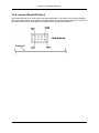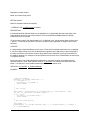
1
P3I3 Frame Grabber Family
p3i_DIG, p3i_CL, p3i_CL/PMC Manual
Revision 2B
Revision Info
2B
2A
1A
new icons, 64 bit support dpe
p3i_CL/PMC added
ew, dpe
First edition
ew, dpe
Copyright © 2001-2011 ELTEC Elektronik AG
1. DISCLAIMER
Copyright
© 2011 ELTEC Elektronik AG. The information, data, and figures in this document
including respective references have been verified and found to be legitimate. In
particular in the event of error they may, therefore, be changed at any time without prior
notice. The complete risk inherent in the utilization of this document or in the results of
its utilization shall be with the user; to this end, ELTEC Elektronik AG shall not accept
any liability. Regardless of the applicability of respective copyrights, no portion of this
document shall be copied, forwarded or stored in a data reception system or entered
into such systems without the express prior written consent of ELTEC Elektronik AG,
regardless of how such acts are performed and what system is used (electronic,
mechanic, photocopying, recording, etc.). All product and company names are
registered trademarks of the respective companies.
Our General Business, Delivery, Offer, and Payment Terms and Conditions shall
otherwise apply.
Federal communications commission statement
•
This device complies with FCC Rules Part 15. Operation is subject to the following
two conditions:
•
This device may not cause harmful interference, and
•
This device must accept any interference received including interference that may
cause undesired operation.
•
This equipment has been tested and found to comply with the limits for a Class B
digital device, pursuant to Part 15 of the FCC Rules. These limits are designed to
provide reasonable protection against harmful interference in a residential
installation. This equipment generates, uses and can radiate radio frequency energy
and, if not installed and used in accordance with manufacturer's instructions, may
cause harmful interference to radio communications. However, there is no guarantee
that interference will not occur in a particular installation. If this equipment does
cause harmful interference to radio or television reception, which can be determined
by turning the equipment off and on, the user is encouraged to try correct the
interference by one or more of the following measures:
•
Reorient or relocate the receiving antenna.
•
Increase the separation between the equipment and receiver.
•
Connect the equipment to an outlet on a circuit different from that to which the
receiver is connected.
•
Consult the dealer or an experienced radio/TV technician for help.
•
The use of shielded cables for connection of the monitor to the graphics card is
required to assure compliance with FCC regulations. Changes or modifications to
this unit not expressly approved by the party responsible for compliance could void
the user's authority to operate this equipment.
Canadian department of communications statement
•
This digital apparatus does not exceed the Class B limits for radio noise emissions
from digital apparatus set out in the Radio Interference Regulations of the Canadian
Department of Communications.
•
This class B digital apparatus complies with Canadian ICES-003
SAFETY INFORMATION
Electrical safety
•
To prevent electrical shock hazard, disconnect the power cable from the electrical
outlet before reloading the system.
•
When adding or removing devices to or from the system, ensure that the power
cables for the devices are unplugged before the signal cables are connected. If
possible, disconnect all power cables from the existing system before you add
device.
•
Before connecting or removing signals cables from motherboard, ensure that all
power cables are unplugged.
•
Make sure that your power supply is set to the correct voltage in your area. If you
are not sure about the voltage of the electrical outlet you are using, contact your
local power company.
•
If the power supply is broken, do not try to fix it by yourself. Contact a qualified
service technician or your retailer.
Operation safety
•
Before installing the motherboard and adding devices on it, carefully read the
manuals that came with the package.
•
Before using the product, make sure all cables are correctly connected and the
power cables are not damaged. If you detect any damage, contact your dealer
immediately.
•
To avoid short circuits, keep paper clips, screws, and staples away from connectors,
slots sockets and circuitry.
•
Avoid dust, humidity, and temperature extremes. Do not place the product in any
area where it may become wet.
•
Place the product on a stable surface.
•
If you encounter technical problems with the product, contact a qualified service
technician or your retailer.
EMC Rules
This unit has to be installed in a shielded housing. If not installed in a properly shielded
enclosure, and used in accordance with the instruction manual, this product may cause
radio interference in which case the user may be required to take adequate measures at
his or her own expense.
IMPORTANT INFORMATION
This product is not an end user product. It was developed and manufactured for further
processing by trained personnel.
Please recycle packaging environmentally friendly: Packaging materials
are recyclable. Please do not dispose packaging into domestic waste
but recycle it.
Please recycle old or redundant devices environmentally friendly: Old
devices contain valuable recyclable materials that should be reutilized.
Therefore please dispose .... old devices at collection points which are
suitable.
Table of Contents
1. Introduction
1.1. About this document
2. Getting Started
2.1. Requirements
2.1.1. Requirements for p3i_DIG
2.1.2. Requirements for p3i_CL and p3i_CL/PMC
2.2. Hardware installation
2.3. Connecting the camera
2.4. Software installation
2.4.1. Windows operating systems
2.4.2. Linux operating systems
3. Hardware Reference
3.1. Introduction
3.1.1. General Features of p3i_DIG
3.1.2. General Features of p3i_CL and p3i_CL/PMC
3.2. p3i_DIG-Hardware
3.2.1. Block Diagram p3i_DIG
3.2.2. Technical Details of p3i_DIG
3.2.3. Connector Pinout of p3i_DIG
3.2.4. Hex-Switch (Board-ID-Select)
3.2.5. Status-LEDs
3.3. p3i_CL-Hardware
3.3.1. Block Diagram p3i_CL
3.3.2. Technical Details of p3i_CL
3.3.3. Connector Pinout of p3i_CL
3.3.4. Hex-Switch (Board-ID-Select)
3.3.5. Status-LEDs
3.4. p3i_CL/PMC-Hardware
3.4.1. Block Diagram p3i_CL/PMC
3.4.2. Technical Details of p3i_CL/PMC
3.4.3. Connector Pinout of p3i_CL/PMC
3.4.4. Jumper (Board-ID-Select)
3.5. Trigger Modes
3.5.1. Softtrigger
3.5.2. Exttrigger
3.5.3. Autotrigger
3.6. Specifications
3.6.1. Electrical Specifications
3.6.2. Environmental Conditions
4. Trouble Shooting - if it does not work
5. Programmers Reference
5.1. Overview
5.1.1. Introduction
5.1.2. Main Features
5.1.3. Technical Details
5.1.4. Software Concept
5.1.5. Source code samples
5.1.6. Industrial requirements
5.1.7. Cameras
5.1.8. Developing own applications
5.1.9. Allocating Image Memory
5.1.10. Multiple Grabbers
5.1.11. Error Handling
vii
1
1
2
2
2
2
2
3
3
3
11
13
13
13
13
14
14
14
19
23
23
24
24
24
28
32
32
33
33
33
37
41
42
42
42
42
43
43
45
46
47
47
47
47
47
48
48
49
49
49
49
49
50
P3I3 Frame Grabber Family
5.1.12. Downloading the software
5.1.13. Image Sequences - Program flow
5.1.14. Calling the library function from languages other than C/C++
5.1.15. Virtual Grabbers
5.2. Library Functions
5.2.1. Overview of library functions
5.2.2. el_Acquire
5.2.3. el_AcquireEx
5.2.4. el_AssignBuffer
5.2.5. el_CloseHW
5.2.6. el_CreateMemBuffer
5.2.7. el_FreeMemBuffer
5.2.8. el_GetBoardIdentifiers
5.2.9. el_GetCycleTime
5.2.10. el_GetDriverRevision
5.2.11. el_GetErrorCode
5.2.12. el_GetErrorCodeEx
5.2.13. el_GetExposureTime
5.2.14. el_GetHWRevision
5.2.15. el_GetNumOfBoards
5.2.16. el_GetPixelClock
5.2.17. el_GetSelectedCamera
5.2.18. el_GetSetting
5.2.19. el_GetSupportedCamFeaturesEx
5.2.20. el_GetSWRevision
5.2.21. el_InitContext
5.2.22. el_InitHW
5.2.23. el_NewMemBuffer
5.2.24. el_OpenHW
5.2.25. el_OpenHWEx
5.2.26. el_ResetOutputs
5.2.27. el_SelectCamera
5.2.28. el_SetAcqWindow
5.2.29. el_SetCycleTime
5.2.30. el_SetExposureTime
5.2.31. el_SetTriggerModes
5.2.32. el_SetExtTriggerInput
5.2.33. el_SetOutputs
5.2.34. el_SetPixelClock
5.2.35. el_TestAcq
5.2.36. el_TestFrameCount
5.2.37. el_WaitAcqEnd
5.2.38. el_WriteSetupFile
5.3. Defines
5.3.1. EL_ACQUISITIONMODE
5.3.2. Error codes
5.3.3. EL_FGITEM
5.4. Data Structures
5.4.1. EL_CAMFEATURES
5.4.2. EL_BOARD_IDENTIFIER
6. Samples
6.1. Programming example
A. Cameras
A.1. Introduction
A.2. Overview of Cameras supported by the software
A.3. T Dalsa Spark SP-13-xxx30 / SP-14-xxx30
A.4. Hitachi KP-F100
viii
50
50
51
51
52
52
53
55
56
58
59
59
60
60
61
61
62
62
62
63
63
64
64
65
65
66
66
68
70
72
73
73
74
75
75
76
76
77
77
78
79
79
81
81
81
81
85
86
86
86
88
88
90
90
90
90
90
P3I3 Frame Grabber Family
A.5. ACC-1xx0 Eagle
A.6. Pulnix TM-6710CL
A.7. Optisens Colorline-1728
A.8. Optisens Colorline-1728 Stereo
A.9. JAI CV-M2 Ikegami SKC-145T2 Basler A102k
B. FAQs
B.1. Common FAQs
ix
90
91
91
92
93
94
94
List of Tables
3.1. Bit Assignments for Appropriate Data Mode of p3i_DIG
3.2. Used SODIMM Capacity Dependent on Selected Data Mode
3.3. Pinout of 100 pin Mini-Delta-Ribbon Connector(Receptacle)
3.4. Pinout of 16-Pin Header X101
3.5. frame grabber LED
3.6. Used SODIMM Capacity Dependent on Selected Data Mode
3.7. Pinout of 26 pin Mini-Delta-Ribbon Connector X1000 (Receptacle)
3.8. Pinout of 15 pin high-density female Min-D (X1002)
3.9. Pinout of 16-Pin Header X101
3.10. frame grabber LED
3.11. Used SODIMM Capacity Dependent on Selected Data Mode
3.12. Pinout of 26 pin Mini-Delta-Ribbon Connector X100 (Receptacle)
3.13. Pinout of 9 pos. Micro-D (X101)
3.14. Pinout of 8 pin Header/Jumper X102
3.15. Electrical Specifications for Differential Signals p3i_DIG
3.16. Electrical Specifications for Differential Signals p3i_CL
3.17. Electrical Specifications for TTL Signals
3.18. Electrical Specifications for Opto-coupled Input Signals
3.19. Power Requirement
3.20. Maximum Pixel Clock Frequency
3.21. Maximum Pixel Clock Frequency
3.22. Environmental Conditions
5.1. Initialization
5.2. Configuration and Video Input
5.3. Acquisition and Buffer Management
5.4. Timing/Synchronisation
5.5. File I/O
5.6. Miscellanious
5.7. Camera Adaptation module functions
5.8. Acquisitionmode
5.9. Warning codes
5.10. Unknown error codes
5.11. Error codes
5.12. Extended error codes
5.13. EL_FGITEM
A.1.
x
15
19
20
22
23
27
29
30
31
32
36
38
39
40
43
43
43
44
44
44
45
45
52
52
52
52
53
53
53
81
81
82
82
84
85
90
Chapter 1. Introduction
1.1. About this document
The purpose of this documentation is to describe the ELTEC Elektronik AG P3I3 frame grabber family. It
contains a description of the hardware and software installation, the list of software APIs and a list of
cameras which can be used with this products.
There are three P3I3 family members. p3i_DIG is a PCI Frame Grabber for Digital Matrix and Line-Scan
cameras. p3i_CL and p3i_CL/PMC are Frame Grabbers for Camera Link applications with PCI and PMC
form factors respectively.
This document contains sections specific for the appropriate P3I3 family member.
The software package is common to all members of the frame grabber family.
1
Chapter 2. Getting Started
2.1. Requirements
2.1.1. Requirements for p3i_DIG
for the installation and use of the p3i_DIG frame grabber you need:
•
the frame grabber board.
•
digital Camera with RS422 or LVDS signaling standard
•
Camera Cable
•
PC with free PCI slot and Pentium CPU.
•
Windows XP, Vista, Windows 7 or a Linux operating system.
•
Operating system dependent hardware driver setup and system independent development files
2.1.2. Requirements for p3i_CL and p3i_CL/PMC
for the installation and use of the p3i_CL and p3i_CL/PMC frame grabber you need:
•
the frame grabber board.
•
CameraLink camera
•
CameraLink cable
•
Computer system with free PCI/PMC slot and Pentium CPU.
•
Windows XP, Vista, Windows 7 or a Linux operating system.
•
Operating system dependent hardware driver setup and system independent development files.
2.2. Hardware installation
•
Switch off computer
•
Prepare site to observe electrostatic discharge (ESD) precautions before opening computer or
removing appropriate P3I3 family member from its case: Touch computer steel case during
insertion/removal of the frame grabber or take other precautions to ensure the absence of high
voltages due to electric charges.
•
Open computer case, remove blind back panel
•
Insert the board into a free PCI/PMC slot; the board must fit into the slot without use of excessive
force, make sure it sits firmly in the slot and the PCI connector conductors sit completely inside the
connector.
•
Fix the back panel with a screw.
•
Close case.
2
Chapter 2. Getting Started
2.3. Connecting the camera
Attach camera cable to camera connector.
2.4. Software installation
Please download our software from the web site ELTEC Elektronik AG [http://www.eltec.de] selecting
Downloadcenter or ask our support( <[email protected]> ).
2.4.1. Windows operating systems
The software package is common to all members of the frame grabber family. For 32 and 64 Bit systems
there is only one setup program. The file program on which system it is running and installs the
corresponding software.
The software consists of :
•
the drivers for Windows XP, Vista, Windows 7 and the DLL that provides the imaging API
•
the configuration tools containing the configuration program and import library for the DLL that
provides the imaging API
2.4.1.1. Driver installation
The next steps are dependent of your operating system.
This chapter describes how to install the lowlevel drivers. The usermode DLL and test-applications are
contained in a different setup.
Please keep the following installation order.
1. Read the documentation.
2. Follow the installation steps described in the next section. Read this section before plugging the
grabber into your computer system.
3. Install the software.
The installation procedure is different for the various operating systems.
Please read the appropriate section.
3
Chapter 2. Getting Started
2.4.1.1.1. Windows XP, Vista, Windows 7
Under these operating systems used the setup program provided for Windows.
2.4.1.1.1.1. Installation
Perform the following steps.
For a first time installation perform the following steps:
1. Shut down your computer system, disconnect power.
2. Plug in the grabber and turn on power.
3. Ignore hardware detection dialogue and start setup program. Select your language
4
Chapter 2. Getting Started
4. Select the directory to install the software. Normally you should keep the default path.
5
Chapter 2. Getting Started
5. Select the components to be installed. On a development system you should install all components. On
a target ''System Drivers'' and maybe ''Test Programs'' are needed.
6
Chapter 2. Getting Started
6. During the installation you have to confirm that you want to install the kernel driver.
7
Chapter 2. Getting Started
7. On a 64 bit system, you will be asked if you want to install the Windows redistributable libraries. You
should keep the default setting to install them.
8
Chapter 2. Getting Started
2.4.1.1.1.2. Update
To update an existing installation, the best way is to deinstall the old and the reinstall the new software.
1. Use the deinstallation routine of the setup program
2. Open the device manager and select ''deinstall'' in the context menu on the grabber.
9
Chapter 2. Getting Started
3. Make sure that the checkbox to remove the driver software is set.
4. If several gabber of a family are shown deinstall all corresponding devices
5. Reboot the system
6. Reinstall the new software
10
Chapter 2. Getting Started
2.4.1.2. Samples installation
2.4.1.3. Starting the configuration program
The configuration program looks the same under Windows and Linux.
•
Start the Configuration Program from the Start-Menu (/Program Files/P3I3 Configuration Tools/P3I3
Configuration)
•
Select the installed board from the List-Box. Now the camera has to be selected from the camera
selection dialog . if your camera does not appear in the list please contact our support (
<[email protected]> )
•
If a Camera is attached, select the Menu Acquisition/Snap to get an image.
More details about the Configuration Program can be found in the Configuration Program online help
details about the adapted cameras can be found in Appendix A.
2.4.1.4. Running the sample digital_grab
This sample shows how to use the library functions. The display is done into a window of the display
server, so the display server has to be started before.
After successful installation of the samples, Visual C++ 6.0 is required to compile and link the sample.
Open the workpace file digital_grab.dsw located in the directory /Program
Files/eltec//samples/digital_grab, compile and link.
After starting the sample a camera can be selected and a new window will be created on the display
server.
2.4.2. Linux operating systems
The Linux driver distribution consists of a kernel driver, which comes in sourcecode and is compiled
during the installation process, a usermode shared library which is only available as binary, the
configuration program and some samples.
The Linux drivers are suitable for development under Intel 32 bit Linux operating systems as e.g. SuSE
Linux and Red Hat Linux.
All files are contained in a compressed tar file, which is called p3i3 -i386-x.y.z.tgz (x.y.z denotes a version
number).
2.4.2.1. Installation
To install the driver, you need the following requirements to be fullfilled.
•
The kernel headerfiles must be installed and match your kernel. Please refer to your linux distribution
manual how to install the kernel sources.
•
The current driver can be downloaded from our website.
To install the driver and samples, please perform the following steps.
1.
Unpack the compressed tar file to a directory of your choice. This can be done as normal user. Open
a shell and use the foolowing commands:
11
Chapter 2. Getting Started
Read the file readme.htm to latest installation hints.
cd directory_of_your_choice
tar xzvf path_and_name_of_tar_file
2.
Login as root
3.
Start the INSTALL script:
./INSTALL
The installation script compiles and installed the driver, copies the shared library to /usr/lib and creates a
link.
You may need to perform some additional steps - e.g. creating entries in /etc/modules.conf. Please read
the file readme.htm for details.
As there are a lot of different linux distributions with many different kernel versions, we can not garantee
that the driver run under all circumstances.
In case of problems please email our support. Attach a copy of the terminal output and error messages.
The subdirectory bin/i386 contains the configuration program. As this program is the same under
Windows and Linux, please have a look at the Windows section of this manual for details.
The subdirectory samples contains some simple samples showing how to access the frame grabber in
our own programs.
2.4.2.2. ELinOS cross development
The Linux drivers are suitable for ELinOS cross developement too. Beneath the i368 drivers there exists
PowerPC drivers for ELTEC BAB740/750 and BAB911 boards.
In order to install for ELinOS cross compilation perform the following steps:
1.
Install ELinOS and create a project for your hardware. This step is beyond the scope of the manual.
Please refer to the ELinOS manual and the manuals coming with the ELTEC BAB boards.
2.
Source the script ELINOS.sh in a shell.
3.
Unpack the tar file to a directory of your choice.
4.
Change to this directory.
5.
Start INSTALL. You need not to bee root !
The steps above create a subdirectory src/grabber in your ELINOS_PROJECT directory. In order to
compile the project with elk, you may need to edit the topmost makefile in your project directory.
Please have a look at the README file coming with the driver archive for additional details.
12
Chapter 3. Hardware Reference
3.1. Introduction
The p3i_DIG is a frame grabber for digital linescan and areascan cameras, which supports EIA-644
(LVDS) as well as RS-422 differential input and output signals. A data bus width of 32-bit together with 7
differential input and 7 differential output signals makes this frame grabber most flexible for use with
different data modes and camera specific signals. In addition multiple trigger in- and outputs
(Opto-coupled and TTL) can be used to fire or recognize external events. In order to minimize the risk of
data loss the onboard SODIMM module buffers high data rates. This is useful especially in cases the PCI
bus is busy or data rate exceeds PCI bus bandwidth.
The p3i_CL and p3i_CL/PMC is a frame grabber for digital linescan and areascan cameras, which
supports the CameraLink standard.The use of the Channel Link technology to transmit multiplexed data
and control signals as well as a serial communication protocol and a standardized connector are the main
benefits of the CameraLink standard.In addition the p3i_CL and p3i_CL/PMC have multiple trigger in- and
outputs (Opto-coupled and TTL) which can be used to fire or recognize external events. In order to
minimize the risk of data loss the onboard SODIMM module buffers high data rates. This is useful
especially in cases the PCI bus is busy or data rate exceeds PCI bus bandwidth.
3.1.1. General Features of p3i_DIG
•
frame grabber for up to four 8-Bit channels of a single camera
•
RS422 and LVDS(RS644) signaling standard supported
•
Restart cameras supported
•
Real-time acquisition of images or image sequences directly into main memory
•
PCI 2.2 compliant
3.1.2. General Features of p3i_CL and p3i_CL/PMC
•
frame grabber supports the CameraLink Base Configuration with up to 3 ports with 8-bit each
•
Restart cameras supported
•
Real-time acquisition of images or image sequences directly into main memory
•
PCI 2.2 compliant
Note that you can use several boards in one computer, in this case the frame grabbers must have
different board IDs. Therefore p3i_DIG and p3i_CL have one Hex-switch and p3i_CL/PMC has one
jumper onboard.
13
Chapter 3. Hardware Reference
3.2. p3i_DIG-Hardware
3.2.1. Block Diagram p3i_DIG
3.2.2. Technical Details of p3i_DIG
The frame grabber is capable of handling 11 different data modes. Cameras with 8 bits to 16 bits per pixel
and multiple channels are supported.
The pixel clock is taken directly from the camera to satisfy setup and hold timings. Additionally the frame
grabber provides a clock output which is programmable in its frequency.
The region of interest, i.e. the part of the video information that is acquired, can be defined on a pixel
basis for all 4 channels - not always the whole frame has to be acquired.
The control signals to synchronize the camera on external events and to adjust variable exposure timings
are programmable via software.
14
Chapter 3. Hardware Reference
3.2.2.1. Data Modes of p3i_DIG
There are 11 different modes for handling several combinations of data inputs. The next table shows the
bit assignments for the appropriate data modes where the channels are marked with A,B,C and D.
A0,B0,C0,D0 are the LSBs of each channel.
Table 3.1. Bit Assignments for Appropriate Data Mode of p3i_DIG
DataBus
Mode0 Mode1 Mode2 Mode3 Mode4 Mode5 Mode6 Mode7 Mode8 Mode9 Mode10
1x8
2x8
3x8
4x8
1x10 2x10 3x10 1x12 2x12 1x16 2x16
VData0
A0
A0
A0
A0
A2
A2
A0
A4
A4
A0
A0
VData1
A1
A1
A1
A1
A3
A3
A1
A5
A5
A1
A1
VData2
A2
A2
A2
A2
A4
A4
A2
A6
A6
A2
A2
VData3
A3
A3
A3
A3
A5
A5
A3
A7
A7
A3
A3
VData4
A4
A4
A4
A4
A6
A6
A4
A8
A8
A4
A4
VData5
A5
A5
A5
A5
A7
A7
A5
A9
A9
A5
A5
VData6
A6
A6
A6
A6
A8
A8
A6
A10
A10
A6
A6
VData7
A7
A7
A7
A7
A9
A9
A7
A11
A11
A7
A7
VData8
B0
B0
B0
B2
A8
B4
A8
A8
VData9
B1
B1
B1
B3
A9
B5
A9
A9
VData10
B2
B2
B2
B4
B0
B6
A10
A10
VData11
B3
B3
B3
B5
B1
B7
A11
A11
VData12
B4
B4
B4
B6
B2
B8
A12
A12
VData13
B5
B5
B5
B7
B3
B9
A13
A13
VData14
B6
B6
B6
A0
B8
B4
B10
A14
A14
VData15
B7
B7
B7
A1
B9
B5
B11
A15
A15
VData16
C0
C0
A0
B6
A2
A2
B0
VData17
C1
C1
A1
B7
A3
A3
B1
VData18
C2
C2
B0
B8
B2
B2
VData19
C3
C3
B1
B9
B3
B3
VData20
C4
C4
C0
A0
A0
B4
VData21
C5
C5
C1
A1
A1
B5
VData22
C6
C6
C2
B0
B6
VData23
C7
C7
C3
B1
B7
VData24
D0
C4
B8
VData25
D1
C5
B9
VData26
D2
C6
B10
VData27
D3
C7
B11
VData28
D4
C8
B12
VData29
D5
C9
B13
VData30
D6
B14
VData31
D7
B15
15
Chapter 3. Hardware Reference
3.2.2.1.1. Mode0 - 1x8 bit
Used DMA channels: 1 4 consecutive bytes are packed into one 32-bit word.
3.2.2.1.2. Mode1 - 2x8 bit
Used DMA channels: 2 4 consecutive bytes of the same channel are packed into one 32-bit word. Each
channel is handled separately and the data is written into different memory buffers.
3.2.2.1.3. Mode2 - 3x8 bit
Used DMA channels: 1 These 24-bits are packed together into one 32-bit word. Unused bits are
zero-filled.
3.2.2.1.4. Mode3 - 4x8 bit
Used DMA channels: 4 4 consecutive bytes of each channel are packed into one 32-bit word. Each
channel is handled separately and the data is written into separate memory buffers.
3.2.2.1.5. Mode4 - 1x10 bit
Used DMA channels: 1 Two consecutive pixels are packed into one 32-bit word, 16-bit aligned. Unused
bits are zero-filled.
3.2.2.1.6. Mode5 - 2x10 bit
Used DMA channels: 2 Two consecutive pixels of each channel are packed into one 32-bit word, 16-bit
aligned and the data is written into separate memory buffers. Unused bits are zero-filled.
3.2.2.1.7. Mode6 - 3x10 bit
Used DMA channels: 3 Three separate buffers, one for each channel, are used to write the image into
main memory. Two consecutive pixels of each channel are packed into one 32-bit word, 16-bit aligned.
Unused bits are zero-filled.
3.2.2.1.8. Mode7 - 1x12 bit
Used DMA channels: 1 Two consecutive pixels are packed into one 32-bit word, 16-bit aligned. Unused
bits are zero-filled.
3.2.2.1.9. Mode8 - 2x12 bit
Used DMA channels: 2 Two consecutive pixels are packed into one 32-bit word, 16-bit aligned. The data
of each channel is written into separate memory buffers. Unused bits are zero-filled.
3.2.2.1.10. Mode9 - 1x16 bit
Used DMA channels: 1 Two consecutive pixels are packed into one 32-bit word, 16-bit aligned.
3.2.2.1.11. Mode10 - 2x16 bit
Used DMA channels: 2 Two consecutive pixels are packed into one 32-bit word, 16-bit aligned. The data
of each channel is written into separate memory buffers.
3.2.2.2. Frame Grabber Interface of p3i_DIG
16
Chapter 3. Hardware Reference
3.2.2.2.1. Digital Video Input
The data input consists of 32 differential line pairs.
3.2.2.2.2. Control Inputs for p3i_DIG
Beside a pixel clock, frame enable, line enable, there are resources for 4 additional user signals(DIFFIN0
to DIFFIN3).
3.2.2.2.3. Control Outputs of p3i_DIG
The p3i_DIG provides three in timing adjustable outputs. These are EXPOSE , PRIN and a selectable
trigger output. The trigger output can be used for instance to fire a strobe light. It is available on the MDR
connector(X100) and on the 16 pos. connector(X101). for each signal a start and end time can be
defined. These signals are generated with the pixel clock, provided by the camera or a programmable
clock. Multiplies of frame enable and line enable signals as timebase are also possible.
EXTCLK is the programmable clock output of p3i_DIG to synchronize cameras.
DIFF_OUT0 to DIFF_OUT3 can be set additionally as static signals.
3.2.2.3. 16 pin Header
The 16-Pin Header is an additional interface for user signals and trigger resources.The user inputs are
readable per software to recognize external events.The user outputs can be set statically.
17
Chapter 3. Hardware Reference
3.2.2.4. Trigger Input
There are several trigger inputs on the frame grabber - optocoupled and TTL. The optocoupled trigger
inputs have optimum noise immunity and 250 V isolation voltage. TriginOpt0+ (Trigger+ in figure below)
for instance is connected to the anode of a LED, TriginOpt0- (Trigger- in figure below) to the cathode of
the LED via an internal 220-Ohm resistor. Since the LED needs about 10..20 mA for full drive, a 5 V
voltage source or a TTL output is able to drive sufficient current through the circuit. Higher-voltage
sources may be used with additional limiting resistors. This trigger input is edge-sensitive. The use of
positive or negative edge is possible.
Caution: Do not exceed a maximum of 30 mA LED current!
Opto-coupled Trigger Input Schematic
3.2.2.5. Data Transfer of p3i_DIG
Since the p3i_DIG is a busmaster card, the video data for a single frame or a whole sequence is moved
into memory per DMA-transfer. There is no need for the CPU to support this process. The maximum
transfer rate in a system is 105 Mbytes/s typically. In a real application the transfer rate depends on the
chipset, graphic card and other active busmaster cards.
3.2.2.6. SODIMM for p3i_DIG
The SODIMM on the p3i_DIG is used as a large FIFO to buffer data especially in cases the PCI bus is
busy or data rate exceeds PCI bus bandwidth.
The SODIMM consists of SDRAM modules and is clocked with 66 MHz. "Non Mixed-Mode" module
configurations are used and each SDRAM module has 4 banks.
18
Chapter 3. Hardware Reference
The used SODIMM capacity is dependent on the selected data mode:
Table 3.2. Used SODIMM Capacity Dependent on Selected Data Mode
MODE
Used SODIMM Capacity [%]
Mode0 (1x8bit)
50
Mode1 (2x8bit)
100
Mode2 (3x8bit (RGB))
75
Mode3 (4x8bit)
100
Mode4 (1x10bit)
62.5
Mode5 (2x10bit)
62.5
Mode6 (3x10bit (RGB))
93.75
Mode7 (1x12bit)
75
Mode8 (2x12bit)
75
Mode9 (1x16bit)
100
Mode10 (2x16bit)
100
3.2.3. Connector Pinout of p3i_DIG
Board Overview
19
Chapter 3. Hardware Reference
3.2.3.1. Frame Grabber Interface X100 of p3i_DIG
Layout of 100 pin Mini-Delta-Ribbon Connector (Receptacle)
This is a 100 pin half pitch Mini Delta Ribbon Connector (MDR) which contains the 32-bit data bus, 7 input
signals, 7 camera control signals, 1 TTL trigger input, 1 TTL trigger output and 1 optocoupled input.
Table 3.3. Pinout of 100 pin Mini-Delta-Ribbon Connector(Receptacle)
SIGNAL NAME
PIN
SIGNAL NAME
PIN
Ground
A1
Ground
B1
TriginTTL0
A2
TrigoutTTL
B2
TriginOpt0+
A3
TriginOpt0-
B3
EXPOSE(+)
A4
EXPOSE(-)
B4
PRIN(+)
A5
PRIN(-)
B5
DIFFOUT_0(+)
A6
DIFFOUT_0(-)
B6
DIFFOUT_1(+)
A7
DIFFOUT_1(-)
B7
EXTCLK(+)
A8
EXTCLK(-)
B8
DIFFOUT_2(+)
A9
DIFFOUT_2(-)
B9
DIFFOUT_3(+)
A10
DIFFOUT_3(-)
B10
PCLK(+)
A11
PCLK(-)
B11
FR_EN(+)
A12
FR_EN(-)
B12
LN_EN(+)
A13
LN_EN(-)
B13
DIFFIN_0(+)
A14
DIFFIN_0(-)
B14
DIFFIN_1(+)
A15
DIFFIN_1(-)
B15
DIFFIN_2(+)
A16
DIFFIN_2(-)
B16
DIFFIN_3(+)
A17
DIFFIN_3(-)
B17
VDATA0(+)
A18
VDATA0(-)
B18
VDATA1(+)
A19
VDATA1(-)
B19
VDATA2(+)
A20
VDATA2(-)
B20
VDATA3(+)
A21
VDATA3(-)
B21
20
Chapter 3. Hardware Reference
VDATA4(+)
A22
VDATA4(-)
B22
VDATA5(+)
A23
VDATA5(-)
B23
VDATA6(+)
A24
VDATA6(-)
B24
VDATA7(+)
A25
VDATA7(-)
B25
VDATA8(+)
A26
VDATA8(-)
B26
VDATA9(+)
A27
VDATA9(-)
B27
VDATA10(+)
A28
VDATA10(-)
B28
VDATA11(+)
A29
VDATA11(-)
B29
VDATA12(+)
A30
VDATA12(-)
B30
VDATA13(+)
A31
VDATA13(-)
B31
VDATA14(+)
A32
VDATA14(-)
B32
VDATA15(+)
A33
VDATA15(-)
B33
VDATA16(+)
A34
VDATA16(-)
B34
VDATA17(+)
A35
VDATA17(-)
B35
VDATA18(+)
A36
VDATA18(-)
B36
VDATA19(+)
A37
VDATA19(-)
B37
VDATA20(+)
A38
VDATA20(-)
B38
VDATA21(+)
A39
VDATA21(-)
B39
VDATA22(+)
A40
VDATA22(-)
B40
VDATA23(+)
A41
VDATA23(-)
B41
VDATA24(+)
A42
VDATA24(-)
B42
VDATA25(+)
A43
VDATA25(-)
B43
VDATA26(+)
A44
VDATA26(-)
B44
VDATA27(+)
A45
VDATA27(-)
B45
VDATA28(+)
A46
VDATA28(-)
B46
VDATA29(+)
A47
VDATA29(-)
B47
VDATA30(+)
A48
VDATA30(-)
B48
VDATA31(+)
A49
VDATA31(-)
B49
Ground
A50
Ground
B50
21
Chapter 3. Hardware Reference
3.2.3.2. 16 pin Header X101
Layout of 16 pin Header (male)
The 16-Pin Header is an additional interface for user signals and trigger resources.
Table 3.4. Pinout of 16-Pin Header X101
Signal Name
Pin
Signal Name
Pin
USER_OUT0
1
Ground
9
USER_OUT1
2
Ground
10
USER_OUT2
3
TriginOpt1+
11
USER_OUT3
4
TriginOpt1-
12
TRIGOUT_TTL
5
Ground
13
TRIGIN_TTL1/USER_IN0
6
Ground
14
TRIGIN_TTL2/USER_IN1
7
TriginOpt2+
15
Ground
8
TriginOpt2-
16
22
Chapter 3. Hardware Reference
3.2.4. Hex-Switch (Board-ID-Select)
Switch S700 is used to set the board ID. If more than one frame grabber is plugged into the PC, each
must have a distinct board ID unequal to "0".
3.2.5. Status-LEDs
There are 4 LEDs for status information:
Frame Grabber LEDs
Table 3.5. frame grabber LED
LED1:
Board selected - when the frame grabber is initialized, the LED is switched
on
LED2:
Capture - Acquisition in progress
LED3:
FiFo overrun - The FiFo has run full
LED4:
FiFo Write Enable - video data is written into the FiFo
These LEDs are not intended to be used in applications but to help in analyzing problems in cooperation
with ELTEC Elektronik AG support.
23
Chapter 3. Hardware Reference
3.3. p3i_CL-Hardware
3.3.1. Block Diagram p3i_CL
3.3.2. Technical Details of p3i_CL
The frame grabber is capable of handling 10 different data modes. Cameras with 8 bits to 16 bits per pixel
and multiple channels are supported.
The pixel clock is taken directly from the camera to satisfy setup and hold timings. Additionally the frame
grabber provides a clock output which is programmable in its frequency.
The region of interest, i.e. the part of the video information that is acquired, can be defined on a pixel
basis for all 3 channels - not always the whole frame has to be acquired.
The control signals to synchronize the camera on external events and to adjust variable exposure timings
are programmable via software.
24
Chapter 3. Hardware Reference
3.3.2.1. Data Modes of p3i_CL
There are 10 different modes for handling several combinations of data inputs.
3.3.2.1.1. Mode0 - 1x8 bit
Used DMA channels: 1 4 consecutive bytes are packed into one 32-bit word.
3.3.2.1.2. Mode1 - 2x8 bit
Used DMA channels: 2 4 consecutive bytes of the same channel are packed into one 32-bit word. Each
channel is handled separately and the data is written into different memory buffers.
3.3.2.1.3. Mode2 - 3x8 bit
Used DMA channels: 3 4 consecutive bytes of the same channel are packed into one 32-bit word. The
data of each channel is handled separately and written into different memory buffers.
3.3.2.1.4. Mode3 - 3x8(RGB) bit
Used DMA channels: 1 These 24-bits are packed together into one 32-bit word. Unused bits are
zero-filled.
3.3.2.1.5. Mode4 - 1x10 bit
Used DMA channels: 1 Two consecutive pixels are packed into one 32-bit word, 16-bit aligned. Unused
bits are zero-filled.
3.3.2.1.6. Mode5 - 2x10 bit
Used DMA channels: 2 Two consecutive pixels of each channel are packed into one 32-bit word, 16-bit
aligned and the data is written into separate memory buffers. Unused bits are zero-filled.
3.3.2.1.7. Mode6 - 1x12 bit
Used DMA channels: 1 Two consecutive pixels are packed into one 32-bit word, 16-bit aligned. Unused
bits are zero-filled.
3.3.2.1.8. Mode7 - 2x12 bit
Used DMA channels: 2 Two consecutive pixels are packed into one 32-bit word, 16-bit aligned. The data
of each channel is written into separate memory buffers. Unused bits are zero-filled.
3.3.2.1.9. Mode8 - 1x14 bit
Used DMA channels: 1 Two consecutive pixels are packed into one 32-bit word, 16-bit aligned. Unused
bits are zero-filled.
3.3.2.1.10. Mode9 - 1x16 bit
Used DMA channels: 1 Two consecutive pixels are packed into one 32-bit word, 16-bit aligned. Unused
bits are zero-filled.
25
Chapter 3. Hardware Reference
3.3.2.2. Frame Grabber Interface p3i_CL
3.3.2.2.1. CameraLink Connector of p3i_CL
The CameraLink standard defines 4 differential inputs with an additional clock to transmit data and control
signals from the camera to the frame grabber (X0..X3). Another four LVDS pairs are reserved for general
purpose camera control. They are outputs of the p3i_CL and flexible programmable via software. To each
of these outputs you can assign a programmable clock, a static signal(high or low) or one of two signals
which have an adjustable hightime and lowtime, for instance for exposure control.
Additionally the CameraLink standard defines an asynchronous serial protocol for a bidirectional
communication between camera and frame grabber. The signals used are SerTfg and SerTc.
3.3.2.3. 16 pin Header
The 16-Pin Header is an additional interface for user signals and trigger resources.The user inputs are
readable per software to recognize external events.The user outputs can be set statically.
3.3.2.4. Trigger Input
There are several trigger inputs on the frame grabber - optocoupled and TTL. The optocoupled trigger
inputs have optimum noise immunity and 250 V isolation voltage. Trigin_Opt+ (Trigger+ in figure below)
for instance is connected to the anode of a LED, Trigin_Opt- (Trigger- in figure below) to the cathode of
the LED via an internal 220-Ohm resistor. Since the LED needs about 10..20 mA for full drive, a 5 V
voltage source or a TTL output is able to drive sufficient current through the circuit. Higher-voltage
sources may be used with additional limiting resistors. This trigger input is edge-sensitive. The use of
positive or negative edge is possible.
Caution: Do not exceed a maximum of 30 mA LED current!
Opto-coupled Trigger Input Schematic
26
Chapter 3. Hardware Reference
3.3.2.5. Data Transfer of p3i_CL
Since the p3i_CL is a busmaster card, the video data for a single frame or a whole sequence is moved
into memory per DMA-transfer. There is no need for the CPU to support this process. The maximum
transfer rate in a system is 105 Mbytes/s typically. In a real application the transfer rate depends on the
chipset, graphic card and other active busmaster cards.
3.3.2.6. SODIMM for p3i_CL
The SODIMM on the p3i_CL is used as a large FIFO to buffer data especially in cases the PCI bus is
busy or data rate exceeds PCI bus bandwidth.
The SODIMM consists of SDRAM modules and is clocked with 66 MHz. "Non Mixed-Mode" module
configurations are used and each SDRAM module has 4 banks.
The used SODIMM capacity is dependent on the selected data mode:
Table 3.6. Used SODIMM Capacity Dependent on Selected Data Mode
MODE
Used SODIMM Capacity [%]
Mode0 (1x8bit)
50
Mode1 (2x8bit)
100
Mode2 (3x8bit)
75
Mode3 (3x8bit (RGB))
75
Mode4 (1x10bit)
62.5
Mode5 (2x10bit)
62.5
Mode6 (1x12bit)
93.75
Mode7 (2x12bit)
75
Mode8 (1x14bit)
87.5
Mode9 (1x16bit)
100
27
Chapter 3. Hardware Reference
3.3.3. Connector Pinout of p3i_CL
Board Overview
3.3.3.1. CameraLink Interface X1000 of p3i_CL
Layout of 26 pin Mini-Delta-Ribbon Connector (Receptacle)
This is a 26 pin half pitch Mini Delta Ribbon Connector (MDR) which contains the data bus, clock, control
signals and the serial communication lines.
28
Chapter 3. Hardware Reference
Table 3.7. Pinout of 26 pin Mini-Delta-Ribbon Connector X1000 (Receptacle)
SIGNAL NAME
PIN
SIGNAL NAME
PIN
inner shield
1
inner shield
14
CC4-
2
CC4+
15
CC3+
3
CC3-
16
CC2-
4
CC2+
17
CC1+
5
CC1-
18
SerTfg+
6
SerTfg-
19
SerTc-
7
SerTc+
20
X3+
8
X3-
21
XClk+
9
XClk-
22
X2+
10
X2-
23
X1+
11
X1-
24
X0+
12
X0-
25
inner shield
13
inner shield
26
3.3.3.2. Trigger Connector X1002 of p3i_CL
Layout of 15 pin high-density female Min-D
This is a 15 pin high-density female Min-D connector which contains Trigger In- and Outputs to fire or
recognize external events.
29
Chapter 3. Hardware Reference
Table 3.8. Pinout of 15 pin high-density female Min-D (X1002)
PIN
SIGNAL NAME
DESCRIPTION
1
GND
Ground
2
Trigin_TTL
selectable Trigger Input;
TTL-Level
3
Trigin_Opt+
selectable Trigger Input;
connected to the Anode of the
Optocoupler
4
Trigin_Opt-
selectable Trigger Input;
connected to the Kathode of
the Optocoupler
5
GND
Ground
6
Trigout_TTL
general purpose trigger output;
for instance, to fire a strobe
light; TTL-Level
7
GND
Ground
8
Contr_Out0+
noninverting part of the
Contr_Out0 signal pair; static
output; LVDS-Level
9
Contr_Out0-
inverting part of the
Contr_Out0 signal pair; static
output; LVDS-Level
10
GND
Ground
11
Contr_Out1+
noninverting part of the
Contr_Out0 signal pair; static
output; LVDS-Level
12
Contr_Out1-
inverting part of the
Contr_Out0 signal pair; static
output; LVDS-Level
13,14,15
NC
No connect
30
Chapter 3. Hardware Reference
3.3.3.3. 16 pin Header X101
Layout of 16 pin Header (male)
The 16-Pin Header is an additional interface for user signals and trigger resources.
Table 3.9. Pinout of 16-Pin Header X101
Signal Name
Pin
Signal Name
Pin
USER_OUT0
1
Ground
9
USER_OUT1
2
Ground
10
USER_OUT2
3
TriginOpt1+
11
USER_OUT3
4
TriginOpt1-
12
TRIGOUT_TTL
5
Ground
13
TRIGIN_TTL1/USER_IN0
6
Ground
14
TRIGIN_TTL2/USER_IN1
7
TriginOpt2+
15
Ground
8
TriginOpt2-
16
31
Chapter 3. Hardware Reference
3.3.4. Hex-Switch (Board-ID-Select)
Switch S700 is used to set the board ID. If more than one frame grabber is plugged into the PC, each
must have a distinct board ID unequal to "0".
3.3.5. Status-LEDs
There are 4 LEDs for status information:
Frame Grabber LEDs
Table 3.10. frame grabber LED
LED1:
Board selected - when the frame grabber is initialized, the LED is switched
on
LED2:
Capture - Acquisition in progress
LED3:
FiFo overrun - The FiFo has run full
LED4:
FiFo Write Enable - video data is written into the FiFo
These LEDs are not intended to be used in applications but to help in analyzing problems in cooperation
with ELTEC Elektronik AG support.
32
Chapter 3. Hardware Reference
3.4. p3i_CL/PMC-Hardware
3.4.1. Block Diagram p3i_CL/PMC
3.4.2. Technical Details of p3i_CL/PMC
The frame grabber is capable of handling 10 different data modes. Cameras with 8 bits to 16 bits per pixel
and multiple channels are supported.
The pixel clock is taken directly from the camera to satisfy setup and hold timings. Additionally the frame
grabber provides a clock output which is programmable in its frequency.
The region of interest, i.e. the part of the video information that is acquired, can be defined on a pixel
basis for all 3 channels - not always the whole frame has to be acquired.
The control signals to synchronize the camera on external events and to adjust variable exposure timings
are programmable via software.
33
Chapter 3. Hardware Reference
3.4.2.1. Data Modes of p3i_CL/PMC
There are 10 different modes for handling several combinations of data inputs.
3.4.2.1.1. Mode0 - 1x8 bit
Used DMA channels: 1 4 consecutive bytes are packed into one 32-bit word.
3.4.2.1.2. Mode1 - 2x8 bit
Used DMA channels: 2 4 consecutive bytes of the same channel are packed into one 32-bit word. Each
channel is handled separately and the data is written into different memory buffers.
3.4.2.1.3. Mode2 - 3x8 bit
Used DMA channels: 3 4 consecutive bytes of the same channel are packed into one 32-bit word. The
data of each channel is handled separately and written into different memory buffers.
3.4.2.1.4. Mode3 - 3x8(RGB) bit
Used DMA channels: 1 These 24-bits are packed together into one 32-bit word. Unused bits are
zero-filled.
3.4.2.1.5. Mode4 - 1x10 bit
Used DMA channels: 1 Two consecutive pixels are packed into one 32-bit word, 16-bit aligned. Unused
bits are zero-filled.
3.4.2.1.6. Mode5 - 2x10 bit
Used DMA channels: 2 Two consecutive pixels of each channel are packed into one 32-bit word, 16-bit
aligned and the data is written into separate memory buffers. Unused bits are zero-filled.
3.4.2.1.7. Mode6 - 1x12 bit
Used DMA channels: 1 Two consecutive pixels are packed into one 32-bit word, 16-bit aligned. Unused
bits are zero-filled.
3.4.2.1.8. Mode7 - 2x12 bit
Used DMA channels: 2 Two consecutive pixels are packed into one 32-bit word, 16-bit aligned. The data
of each channel is written into separate memory buffers. Unused bits are zero-filled.
3.4.2.1.9. Mode8 - 1x14 bit
Used DMA channels: 1 Two consecutive pixels are packed into one 32-bit word, 16-bit aligned. Unused
bits are zero-filled.
3.4.2.1.10. Mode9 - 1x16 bit
Used DMA channels: 1 Two consecutive pixels are packed into one 32-bit word, 16-bit aligned. Unused
bits are zero-filled.
34
Chapter 3. Hardware Reference
3.4.2.2. CameraLink Connector of p3i_CL/PMC
The CameraLink standard defines 4 differential inputs with an additional clock to transmit data and control
signals from the camera to the frame grabber (X0..X3). Another four LVDS pairs are reserved for general
purpose camera control. They are outputs of the p3i_CL and flexible programmable via software. To each
of these outputs you can assign a programmable clock, a static signal(high or low) or one of two signals
which have an adjustable hightime and lowtime, for instance for exposure control.
Additionally the CameraLink standard defines an asynchronous serial protocol for a bidirectional
communication between camera and frame grabber. The signals used are SerTfg and SerTc.
3.4.2.3. 8 pin Header/Jumper
The 8 pin Header/Jumper is an additional interface for an user input or an trigger input. The user input is
readable per software to recognize an external event. Additionally user outputs can be set statically.
3.4.2.4. Trigger Input
There are several trigger inputs on the frame grabber - optocoupled and TTL. The optocoupled trigger
inputs have optimum noise immunity and 250 V isolation voltage. Trigin_Opt+ (Trigger+ in figure below)
for instance is connected to the anode of a LED, Trigin_Opt- (Trigger- in figure below) to the cathode of
the LED via an internal 220-Ohm resistor. Since the LED needs about 10..20 mA for full drive, a 5 V
voltage source or a TTL output is able to drive sufficient current through the circuit. Higher-voltage
sources may be used with additional limiting resistors. This trigger input is edge-sensitive. The use of
positive or negative edge is possible.
Caution: Do not exceed a maximum of 30 mA LED current!
Opto-coupled Trigger Input Schematic
35
Chapter 3. Hardware Reference
3.4.2.5. Data Transfer of p3i_CL/PMC
Since the p3i_CL/PMC is a busmaster card, the video data for a single frame or a whole sequence is
moved into memory per DMA-transfer. There is no need for the CPU to support this process. The
maximum transfer rate in a system is 105 Mbytes/s typically. In a real application the transfer rate
depends on the chipset, graphic card and other active busmaster cards.
3.4.2.6. SODIMM for p3i_CL/PMC
The SODIMM on the p3i_CL/PMC is used as a large FIFO to buffer data especially in cases the PCI bus
is busy or data rate exceeds PCI bus bandwidth.
The SODIMM consists of SDRAM modules and is clocked with 66 MHz. "Non Mixed-Mode" module
configurations are used and each SDRAM module has 4 banks.
The used SODIMM capacity is dependent on the selected data mode:
Table 3.11. Used SODIMM Capacity Dependent on Selected Data Mode
MODE
Used SODIMM Capacity [%]
Mode0 (1x8bit)
50
Mode1 (2x8bit)
100
Mode2 (3x8bit)
75
Mode3 (3x8bit (RGB))
75
Mode4 (1x10bit)
62.5
Mode5 (2x10bit)
62.5
Mode6 (1x12bit)
93.75
Mode7 (2x12bit)
75
Mode8 (1x14bit)
87.5
Mode9 (1x16bit)
100
36
Chapter 3. Hardware Reference
3.4.3. Connector Pinout of p3i_CL/PMC
Board Overview
3.4.3.1. CameraLink Interface X100 of p3i_CL/PMC
Layout of 26 pin Mini-Delta-Ribbon Connector (Receptacle)
This is a 26 pin half pitch Mini Delta Ribbon Connector (MDR) which contains the data bus, clock, control
signals and the serial communication lines.
37
Chapter 3. Hardware Reference
Table 3.12. Pinout of 26 pin Mini-Delta-Ribbon Connector X100 (Receptacle)
SIGNAL NAME
PIN
SIGNAL NAME
PIN
inner shield
1
inner shield
14
CC4-
2
CC4+
15
CC3+
3
CC3-
16
CC2-
4
CC2+
17
CC1+
5
CC1-
18
SerTfg+
6
SerTfg-
19
SerTc-
7
SerTc+
20
X3+
8
X3-
21
XClk+
9
XClk-
22
X2+
10
X2-
23
X1+
11
X1-
24
X0+
12
X0-
25
inner shield
13
inner shield
26
3.4.3.2. Trigger Connector X101 of p3i_CL/PMC
Layout of 9 pos. Micro-D (plug)
This is a 9 pos. thumbscrew Micro-D plug connector which contains Trigger In- and Outputs to fire or
recognize external events.
38
Chapter 3. Hardware Reference
Table 3.13. Pinout of 9 pos. Micro-D (X101)
PIN
SIGNAL NAME
DESCRIPTION
1
TRIGIN0+
noninverting part of
optocoupled trigger input0
2
TRIGIN2+
noninverting part of
optocoupled trigger input2
3
ContrDiffOut5+
noninverting part of differential
output; LVDS level
4
TrigoutTTL0
TTL Trigger output;
programmable by software
5
GND
Ground
6
TRIGIN0-
inverting part of optocoupled
trigger input0
7
TRIGIN2-
inverting part of optocoupled
trigger input2
8
ContrDiffOut5-
inverting part of differential
output; LVDS level
9
TriginTTL1_UserIn0
Trigger input; also readable by
software; TTL-Level
39
Chapter 3. Hardware Reference
3.4.3.3. 8 pin Header/Jumper X102
Layout of 8 pin Header/Jumper (male)
The 8 pin Header/Jumper is an additional interface for user signals and trigger resources.
Table 3.14. Pinout of 8 pin Header/Jumper X102
PIN
SIGNAL NAME
DESCRIPTION
1
GND
Ground for BoardID Jumper
2
BoardID
Signal for BoardID Jumper
3
GND
Ground
4
TRIGIN_TTL2_USERIN1
TTL Trigger input; also
readable by software
5
GND
Ground
6
User_Out0
settable by software;
TTL-Level
7
User_Out1
settable by software;
TTL-Level
8
User_Out2
settable by software;
TTL-Level
40
Chapter 3. Hardware Reference
3.4.4. Jumper (Board-ID-Select)
8 pin Header/Jumper X102 is also used to set different BoardIds. If you want to use two frame grabbers
with one computer system, each must have a distinct board ID. If jumper is attached from pin1 to pin2 of 8
pin Header/Jumper X102, the BoardId is 1 (Default). With no jumper the BoardId is 3.
41
Chapter 3. Hardware Reference
3.5. Trigger Modes
The P3I3 family members support various trigger modes to satisfy the requirements of varying
applications. There are three main modes of operation to distinguish: Softtrigger, Exttrigger and
Autotrigger. For all three modes the necessary timing informations for the camera control signals has to
be set by software before operation begins. Refer to the sofware section for adjustable parameters. Both
frame grabbers are capable of handling a frame and a line trigger. The trigger inputs are selectable via
software and are located either at the connector(s) at the frontpanel or the 16 pos. connector.
3.5.1. Softtrigger
In the "Softtrigger Mode" the software defines the starting point of the generated timing. The grabber
repeats this timing until it is stopped again by the software.
3.5.2. Exttrigger
In the "Exttrigger Mode" acquisition and timing is started by external events on the falling or rising edge of
the selected trigger input. After the programmed timing has expired the grabber waits for the next trigger
edge to repeat the control cycle. Working with two triggers, e.g. frame trigger and line trigger, is also
possible.
3.5.3. Autotrigger
In the "Autotrigger Mode" acquisition and timing is started by external events on the falling or rising edge
of the selected trigger input. After the programmed timing has expired the grabber repeats the control
cycle immediately. Working with two trigger, e.g. frame trigger and line trigger, is also possible.
42
Chapter 3. Hardware Reference
3.6. Specifications
3.6.1. Electrical Specifications
3.6.1.1. Specifications for Differential Signals p3i_DIG
Every differential input signal pair is terminated with a parallel 100 Ohm resistor.
Table 3.15. Electrical Specifications for Differential Signals p3i_DIG
Parameter
Description
Min
Typ
High Level Input Voltage VIH
At any differential signal pin
Low Level Input Voltage VIL
At any differential signal pin
-0.5
V
Differential Output Voltage
|VOD|
when using RS422 signaling
standard
2
V
Differential Output Voltage
|VOD|
when using LVDS signaling
standard
240
Common Mode Output
Voltage VCO
when using RS422 signaling
standard
1.8
V
Common Mode Output
Voltage VCO
when using LVDS signaling
standard
1.2
V
340
Max
Unit
3.8
V
454
mV
3.6.1.2. Specifications for Differential Signals p3i_CL and p3i_CL/PMC
Table 3.16. Electrical Specifications for Differential Signals p3i_CL
Parameter
Description
Min
High Level Input Voltage VIH
At any differential signal pin
Low Level Input Voltage VIL
At any differential signal pin
Differential Output Voltage
|VOD|
Typ
Max
Unit
3.8
V
-0.5
240
Common Mode Output
Voltage VCO
V
340
454
1.2
mV
V
3.6.1.3. Specifications for TTL Signals
Table 3.17. Electrical Specifications for TTL Signals
Parameter
Description
Min
High-Level Output Voltage
VOH
Typ
Max
2
Low-Level Output Voltage
VOL
V
0.7
43
Unit
V
Chapter 3. Hardware Reference
High-Level Output Current
|IOH|
32
mA
Low-Level Output Current
|IOL|
64
mA
3.6.1.4. Specifications for Opto-coupled Input Signals
Table 3.18. Electrical Specifications for Opto-coupled Input Signals
Parameter
Description
Min
Typ
Input forward current If(on)
to turn output on
6.3
15
Input forward current If(off)
to turn output off
0
Max
Unit
mA
250
uA
Max
Unit
3.6.1.5. Power Requirement
Table 3.19. Power Requirement
Parameter
Description
Min
Icc(max)
Power supply +5V over
PCI-Connector with
SODIMM(64MB)
Typ
1.2
A
3.6.1.6. Pixel Clock Frequency of p3i_DIG
Table 3.20. Maximum Pixel Clock Frequency
Parameter
Description
Clock-f
Min
Max
Unit
For
Mode0(1x8),Mode1(2x8),Mode4(1x10),
Mode7(1x12),
Mode9(1x16)when using
LVDS signaling standard
41
MHz
Clock-f
For all other modes when
using LVDS signaling standard
38
MHz
Clock-f
when using RS422 signaling
standard
30
MHz
44
Typ
Chapter 3. Hardware Reference
3.6.1.7. Pixel Clock Frequency p3i_CL and p3i_CL/PMC
Table 3.21. Maximum Pixel Clock Frequency
Parameter
Description
Clock-f
Clock-f
Min
Typ
Max
Unit
for Mode0(1x8 bit), Mode1(2x8
bit), Mode4(1x10 bit),
Mode6(1x12 bit), Mode8(1x14
bit), Mode9(1x16 bit)
66
MHz
for Mode2(3x8 bit), Mode3(3x8
bit RGB), Mode5(2x10 bit),
Mode7(2x12 bit)
38
MHz
3.6.2. Environmental Conditions
Table 3.22. Environmental Conditions
Storage Temperature:
-20° C - 70° C
Operating Temperature:
0° C - 45°C (2 m/s forced air cooling)
Maximum Operating Humidity:
85 % relative
45
Chapter 4. Trouble Shooting - if it does not work
Check if the driver and the user mode software are installed properly. See chapter Getting Started.
Frame Grabber is not found by software:
Make sure the grabber is correctly plugged into the PCI-connector. If mechanical problems can be
excluded refer to the driver installation guide to see if the driver has been installed correctly. Mixing up the
recommended installation order of hard and software can be a possible reason for an incorrectly installed
driver.
No image at all:
Watch the four Status-LEDs when starting the acquisition.If there is no LED switched on the grabber was
not found by software. Refer to the driver installation guide. When only LED1 (Board select) and Led2
(Acquisition in progress) are switched on the grabber may receive no frame enable, no line enable or no
pixel clock. Check if MDR connector is plugged properly and camera is running.
Getting support:
Under some circumstances you may not succeed in getting everything running. Then you can contact us but we need the system configuration as exactly as possible. For that purpose we have prepared a
support request form where you can fill in your configuration and submit this form (by fax or E-mail)
together with the support request - using this form will help us to help you faster.
46
Chapter 5. Programmers Reference
5.1. Overview
5.1.1. Introduction
Frame Grabber configuration tools is the software foundation for ELTEC Elektronik AG frame grabber
family.
It is the unified interface used across all frame grabber products.
Frame Grabber configuration tools is one of the most powerful low-level frame grabber interfaces
available on the market.
It combines three essential advantages:
•
Fast and optimized access to the frame grabber hardware.
•
Relieves the program developer from all hardware dependent stuff.
•
Unifies the frame grabber interface to switch between the grabber family members.
Special care has been taken to simplify the use of complex camera features like restart-reset modes or
acquisition of image sequences.
Applications ranging from simple single image grabbing, up to programming your frame grabber to
become a real image sequence machine, are all easily supported by Frame Grabber configuration tools.
5.1.2. Main Features
•
Generic software interface for the grabber product line.
•
Real-time image acquisition
•
Configuration and setup utility included
•
Easy setup file handling to store different configurations.
•
Powerful virtual to physical memory management during run-time.
•
Makes handling of image sequences as easy as single images.
•
DLL with complete frame grabber control.
5.1.3. Technical Details
The heart of each frame grabber is ist PCI DMA controller.
All boards work without the need of a frame buffer on-board. Image data is stored directly in the PC s
main memory. ELTEC Elektronik AG is using one of the most sophisticated PCI DMA controllers
available. ELTEC Elektronik AG frame grabber DMA means FAST & FLEXIBLE. Flexible DMA schemes
(scatter-gather DMA - known from UNIX network drivers) allow the acquisition of complete sequences
without CPU intervention and without missing a single frame. So, the main advantage of the PCI bus, fast
47
Chapter 5. Programmers
Reference
data transfer PCI burst transfers is extended by ELTEC Elektronik AG with an intelligent PCI DMA.
The Frame Grabber configuration tools make all these features available at your finger tips. ELTEC
Elektronik AG s scatter-gather DMA is used to handle paged ad-dresses, resulting in linear, contiguous
images appearing in main memory for easy access. With Frame Grabber configuration tools and your
frame grabber you are able to break through all restrictions which exist on other PCI frame grabber
solutions:
•
Your frame grabber is able to acquire directly into linear memory.
•
Frame buffer memory is allocated during run-time, NOT during Windows® startup; Low-level software
supplied.
•
Drivers for Windows XP, Vista, Windows 7 with acquisition into main memory.
•
Windows® -based test/setup program.
•
On-line documentation supplied as Windows® Help.
•
Reallocation of frame buffer memory is easy
With this flexible memory management of the Frame Grabber configuration tools it is easy to use the
whole available main memory of your PC to store numbers of different and long image sequences, filling
many megabytes of memory. It is as easy as storing a single frame. Only this flexibility gives you the
security that your application is able to adapt to different memory needs during run-time and is able to use
the whole memory which is physically available on your PC.
5.1.4. Software Concept
Frame Grabber configuration tools consists of a device driver and a Dynamic Link Library (DLL). It is only
natural that the DLL supports the whole frame grabber hardware.
Setup of ADC, look-up table, offset/gain, camera multiplexer, region of interest (acquisition window
dimensions), camera selection and setup file support are part of the DLL. Permanent (live), single shot
and sequence acquisition of images can be requested and the various states of the acquisition
(active/finished) can be inquired.
A test and setup utility, running also under Windows®, allows to adjust all relevant camera parameters
and have them stored by the DLL in a file for further use in user applications. It supplies
Video-in-a-Window display by using Windows® functions, thus enabling overlapped acquisition windows.
The same utility supports test and configuration of the frame grabber board under Windows®.
5.1.5. Source code samples
Sample source code for using the driver DLL with custom imaging routines is included as well as sample
code to set up the frame grabber board, start single shot acquisition and display the image with
Windows® display functions and DirectDraw®.
With Frame Grabber configuration tools you are able to concentrate on the important things of the
application and not waste time with the Frame Grabber hardware.
Please have a look at the code example below to see how easy it is to set up a frame grabber board and
acquire an image sequence, which could include as many frames as you want (dependent on the
available PC main memory).
The samples can be downloaded from ELTEC Elektronik AG [http://www.eltec.de] selecting
48
Chapter 5. Programmers
Reference
support/drivers and updates.
5.1.6. Industrial requirements
Frame Grabber configuration tools has an extensive built-in camera support making it extremely easy to
use non-standard camera features (e.g. restart/reset).
Further, all signals essential to industrial applications are integrated into the Frame Grabber configuration
tools. Signals for pixel synchronous acquisition (external clock) and process control (external trigger) are
supported.
5.1.7. Cameras
With the default jumpering the board is set up for the use of CCIR/EIA-Cameras with no special features.
The software supports this camera types by default.
A list of cameras with special features which are already adapted to the software can be found in
Appendix A.
5.1.8. Developing own applications
The supplied software includes all the files you need to develop applications. It is required that you
include only one header file. This file includes all constant definitions, type definitions and function
prototypes. After compiling your application you need to link it with one of the different libraries. if your
application is to run under Windows, you need to link it with the import library eleye516.lib and run it using
the dll eleye516.dll. Note that the camera file eleye516.cam ( see Appendix A ) has to reside in the same
directory as eleye516.dll. see ELTEC Elektronik AG [http://www.eltec.de] selecting support/drivers and
updates for examples of application development using VC++
5.1.9. Allocating Image Memory
The advanced security-technique and virtual address-concepts of modern operation systems makes it
more difficult to request image memory which is accessible on fixed addresses or by multiple applications.
Additionally, modern video hardware is using flexible and fast DMA data transfers to move the images to
memory. But using DMA means that access to physical memory is needed to transfer the image data into
on board or system memory.
There are several solutions to provide the video hardware with necessary physical addresses. With
ELTEC Elektronik AG's imaging API there are different possibilities to request or to create image memory.
Dependent on the operating system used the library function el_InitHW() and el_NewMemBuffer() are
able to work with user defined or internal defined image buffers.
In general the library function mentioned above are allocating image memory and the user needs not to
care about requesting access permission and organizing and mapping the physical image memory to the
virtual address space of a user program. After the acquisition is finished the application is able to access
images in a very transparent way by using the supplied image pointers to walk through the image.
But there are different conditions depending on the operating system used to work with image memory
allocated by the application. For example if an application must use fixed memory addresses or more
than one application must access the image data to process different areas of the image simultaneous.
For this purposes the functions el_InitHW() and el_NewMemBuffer() are able to work with user defined
image buffers in the same way as they work with buffers defined inside these functions.
5.1.10. Multiple Grabbers
The software can handle multiple grabbers using the same library. The grabbers need not to be of the
49
some kind they must only belong to the same 'family' like , , , and .
Because the grabbers of a family may have different hardware resources the function of a few API calls
might differ slightly. Please referer to the software reference.
Using grabbers of different families is more complicated because two libraries have to be used. This leads
to a collision of the function names in the libraries. So simple linking of both libraries to an application
does not work.Bit depending on the operation system the are possibilites, like dynamical linking, to
overcome this problem.
5.1.11. Error Handling
In case of failure of a function call, the function el_GetErrorCode can be used to get information of the
cause. A list of error codes follows later in this chapter.
5.1.12. Downloading the software
Please download our software from the web site ELTEC Elektronik AG [http://www.eltec.de] selecting
support/drivers and updates or ask our support ( <[email protected]> ).
5.1.13. Image Sequences - Program flow
Image sequences are a very versatile tool for solving some common problems in imaging:
Functional description:
An image sequence consists of a n frames. Each frame is located at a contiguous memory region, the
different frames are not allocated contiguously, however. A single snapshot means that a complete
sequence of frames is acquired without any CPU intervention. After the snapshot all frames of the
sequence are present in memory. Continuous acquisition (live) means that after the last frame of the
sequence is in memory the acquisition starts again with the first frame.
Swing buffers:
Swing buffers are used for continuous acquisition where one image buffer is being acquired into and the
other is being evaluated; after one frame time the role of the two buffers is interchanged. The most
common method is to implement them with interrupts. However, image sequences can be used here,
also. A short sequence of 2..4 frames with continuous acquisition makes a first-class swing (ping-pong)
buffer.
How far has the acquisition progressed?
Since the acquisition is done completely in hardware, the CPU has no implicit knowledge about which
frame is ready for image processing: It can be inquired by el_TestFrameCount. Another method is to write
a distinct pattern (0xFF00FF00 e.g.) into frame memory and to test if it has been overwritten by the
acquisition process.
SAMPLE:
// This sample shows the overall sequence of settings things up and acquiring a sequence.
int SizeX=748;
int SizeY=576;
int NumberOfFrames = 100;
/* This needs more than 40 MB of main memory */
BoardId = el_OpenHW( 0, 0); /* Get board handle */
el_InitContext( BoardId, SetupFileName);
/* Initialize library software structures */
50
/* Initialize HW and allocate frame buffer */
framearray =(BYTE**)el_InitHW( BoardId, 0, SizeX, SizeY, NumberOfFrames, 0, 0);
/* optional change of hardware parameters come here */
el_Acquire( BoardId, EL_SNAP); /* real-time acquisition of 100 frames */
el_WaitAcq( BoardId);
/* wait until sequence has been acquired */
/* optional display the sequence */
/* image processing comes here */
el_Close(BoardId, 0);
/* clean up library structures, close HW */
5.1.14. Calling the library function from languages other than C/C++
All library functions (e.g. el_OpenHW) are exported wiht _cdecl calling conventions. To be able to use the
library from other languages (e.g. Visual Basic) all routines are exported as _stdcall too. These _stdcall
version are named the same, but have a second _. The _stdcall version of el_OpenHW is el__OpenHW.
Usage under Visual Basic
To use the dll functions under Visual Basic you must declare them. Declare Function el__OpenHW Lib
"eleyeX16" (ByVal HexSwitch As Long, ByVal Mode As Long) As Long
eleyeX16 must be replace be the name of the DLL.
Usage under Pascal
For Pascal or Delphi you can use the _cdecl version as well. Declare the routines in a seperate unit.
Example
Unit grabber_routines;
interface
{ The "cdecl" Version is used. }
function el_OpenHW(HexSwitch, Mode: longint):longint; cdecl;
...
implementation
const LIBNAME = 'eleyex16.dll';
function el_OpenHW; cdecl; external LIBNAME;
...
begin
end.
eleyex16.dll denotes the name of the dll.
5.1.15. Virtual Grabbers
The use Virtuals Grabbers is a concept to handle several independent units on one piece of hardware. So
it is possibe to control a colour and a black and white aquisition unit as two grabbers.
Virtual grabbers are opened using el_OpenHWEx the hex switch selects the board and the SubId
parameter is used to select one of the virtual grabber one the board. el_OpenHW can still be used but it
51
Chapter 5. Programmers
Reference
can only open the first virtual grabber.
Because the units on a board might not be totally independent virtual grabbers have to be opened and
used within one process. If multitasking is required threads have to be used.
Virtual grabbers can be identified with el_GetBoardIdentifiers . If at least one "SubId" element in the list
filled with EL_BOARD_IDENTIFIER structures is not eqal 0 all grabbers with the same HexSwitch
element are virtual grabbers.
5.2. Library Functions
5.2.1. Overview of library functions
Table 5.1. Initialization
Initialization
el_OpenHW
el_InitContext
el_InitHW
el_CloseHW
Table 5.2. Configuration and Video Input
Configuration and Video Input
el_SelectCamera
el_GetSelectedCamera
el_GetSupportedCamFeaturesEx
Table 5.3. Acquisition and Buffer Management
Acquisition and Buffer Management
el_Acquire
el_AcquireEx
el_SetAcqWindow
el_NewMemBuffer
el_FreeMemBuffer
el_AssignBuffer
el_CreateMemBuffer
Table 5.4. Timing/Synchronisation
Timing/Synchronisation
el_WaitAcqEnd
52
Chapter 5. Programmers
Reference
el_TestFrameCount
el_TestAcq
Table 5.5. File I/O
File I/O
el_WriteSetupFile
Table 5.6. Miscellanious
Miscellanious
el_SetOutputs
el_ResetOutputs
el_GetSetting
el_GetNumOfBoards
el_GetSWRevision
el_GetHWRevision
el_GetErrorCode
el_GetErrorCodeEx
Table 5.7. Camera Adaptation module functions
Camera Adaptation module functions
el_SetTriggerModes
el_SetExtTriggerInput
el_SetPixelClock
el_SetExposureTime
el_SetCycleTime
el_GetPixelClock
el_GetExposureTime
el_GetCycleTime
5.2.2. el_Acquire
long
el_Aquire (long BoardId, EL_ACQUISITIONMODE Mode);
Starts acquisition for a single frame/field (snap) or for continuous (live) acquisition
PARAMETERS:
BoardId : board ID returned by el_OpenHW
53
Mode:
•
live: EL_LIVE
•
snap: EL_SNAP
•
or be aborted: EL_ABORT
RETURN VALUE:
0 if OK
-1 if ERROR See el_GetErrorCode for details.
DESCRIPTION:
Single buffer acquisition:
EL_LIVE: switches to live mode. A continuous real-time acquisition takes place.
EL_SNAP: If acquisition is in live mode the acquisition is terminated after the current image has been
acquired. If not in live mode, the acquisition is started for a single frame/field. The acquisition stops
automatically after one frame/field has been acquired. Use el_TestAcq to wait for acquisition complete.
Image sequence acquisition:
An image sequence is defined with el_InitHW or el_NewMemBuffer if a FrameCount greater than '1' was
supplied. Then the following behavior can be expected with el_Acquire :
EL_LIVE starts an endless sequence acquisition (ring buffer acquisition). In such a case the number of
the current frame can be inquired with el_TestFrameCount .
EL_SNAP acquires exactly one sequence ( number of frames acquired is equal to FrameCount ). Use
el_TestFrameCount to detect the acquisition of a frame inside a sequence or el_TestAcq to wait for the
whole sequence to complete. See also: Sequences
Acquisition and external trigger:
If an external trigger is supplied to control the acquisition, the video hardware should be switched to live
mode (call el_Acquire with parameter mode set to EL_LIVE). In case of single-buffer acquisition each
trigger pulse causes the hardware to acquire exactly one frame/field. In case of sequence acquisition
each trigger causes the hardware to acquire one frame of the sequence. If you call el_Acquire with mode
set to EL_SNAP, the first following pulse causes an acquisition. Every following pulse has no effect.
Therefore, EL_SNAP can be used to disable external trigger acquisition temporarily. EL_ABORT can be
used to disable image acquisition imediately.
CAVEATS:
el_Acquire returns immediately. Therefore, el_TestAcq has to be used to determine the end of an
acquisition. There are several other options to inquire the status of an acquisition. Refer to the
descriptions of the different el_Test functions supplied in the on-line help.
If live mode is selected and image processing as well as display is active during acquisition, the PCI bus
bandwidth may be exceeded, which can be seen from a rolling picture .
EXAMPLE : see el_OpenHW
54
SEE ALSO: EL_ACQUISITIONMODE, el_OpenHW , el_NewMemBuffer
5.2.3. el_AcquireEx
long
el_AquireEx (long BoardId, EL_ACQUISITIONMODE Mode, long *pChannels, long
*pStart, long *pLength, long NoOfChan, long Reserved);
Starts acquisition for a single frame/field (snap) or for continuous (live) acquisition
PARAMETERS:
BoardId : board ID returned by el_OpenHW
Mode:
•
live: EL_LIVE
•
snap: EL_SNAP
•
or be aborted: EL_ABORT
pChannels: is intended to select specific channles, not used at the moment set to 0
pStart: array with index of start frame, for each channel
pLength: array with length of each sub sequence, for each channel
NoOfChan: length of arrays used before, 4 for most grabbers, 1 for
Reserved: set to 0
RETURN VALUE:
0 if OK
-1 if ERROR See el_GetErrorCode for details.
DESCRIPTION:
This function is an extended version of el_Acquire . for a geneal description have a look there.
el_AcquireEx is used to start an aquisiton on the given chanels filling just a part of the originally allocated
sequence(s). The start positions for each channel have to be stored in the pStart array. The length of the
sequences in the pLength array.
Future versions of the software might use the pChannels array to select special DMA channels. At the
moment a 0 pointer has to be used for pChannels and all channels are set up by the function. So
NoOfChan has to be ser to 1 for and to 4 for all other grabbers.
It is possible to assign one buffer to more than one channel. If one buffer withe the sequence length
SEQ_LEN has been assigned to all DMA channels the example below would fill the first quater of the
buffer with data from the first camera, the second quater with dater from the second camera and so on.
An overlapping of subsequences in one buffer is not allowed and can lead to unpredictable effects.
EXAMPLE :
55
Chapter 5. Programmers
Reference
#define CHNO 4 // number of channels
long pStart[CHNO];
pStart[0] = 0;
pStart[1] = 2 * SEQ_LEN/4;
pStart[2] = 3 * SEQ_LEN/4;
pStart[3] = 4 * SEQ_LEN/4;
long pLength[CHNO];
pLength[0] = SEQ_LEN/4;
pLength[1] = SEQ_LEN/4;
pLength[2] = SEQ_LEN/4;
pLength[3] = SEQ_LEN/4;
el_AcquireEx(BoardId, EL_SNAP, 0, pStart, pLength, CHNO, 0);
SEE ALSO: el_Acquire
5.2.4. el_AssignBuffer
void **
el_AssignBuffer ( long BoardId, long ChannelNumber, long BufferNo, double
ScaleX, double ScaleY, long Reserved1, long Reserved2 );
Assigns a memory buffer to a DMA channel. The scaling factors are fixed to 1.0 .
PARAMETERS:
BoardId : board ID returned by el_OpenHW
ChannelNumber : DMA channel (0,1,2,3)
BufferNo :Buffer number returned by el_CreateMemBuffer
ScaleX : Scaling factor X-size 1.0
ScaleY : Scaling factor Y-size 1.0
Reserved1 : reserved for future use
Reserved2 : reserved for future use
RETURN VALUE:
Pointer to pointer array if OK
0 if ERROR. See el_GetErrorCode for details.
Description:
SEE ALSO: el_CreateMemBuffer
EXAMPLE:
Allocate four buffers, each one for the channels for
//
// in our sample we will suppose only one frame sequence
56
Chapter 5. Programmers
Reference
//
nSequenceLength = 1;
//
// free all buffer before allocating new
//
long BuffId;
for(int i=0; i<4; i++)
{
NewBuffIds[i]=0;
}
for( i=0; i<4; i++)
{
// get buffer ID assigned to channel i
BuffId=el_GetSetting(nBoardID, EL_BUFFERID, i);
// delete buffer
if(BuffId >0) el_FreeMemBuffer(0,BuffId);
}
//
// Allocate four buffers, each one for the channels for
//
ppVideoMemory_0 = el_InitHW( nBoardID, NULL, nSizeX, nSizeY, nSequenceLength ,
0, &NewBuffIds[0]);
if (ppVideoMemory_0 < 0 )
{
ReportError( "el_InitHW" );
return;
}
el_AssignBuffer(nBoardID,0, NewBuffIds[0], 1.0, 1.0, 0, 0);
ppVideoMemory_1 = el_CreateMemBuffer(nBoardID, 0, nSizeX, nSizeY,
(long *) &nSequenceLength, 0, EL_PACKER_Y, EL_INTERLACE, &NewBuffIds[1]);
if (ppVideoMemory_1 < 0 )
{
ReportError( "el_CreateMemBuffer" );
return;
}
el_AssignBuffer(nBoardID,1, NewBuffIds[1], 1.0, 1.0, 0, 0);
ppVideoMemory_2 = el_CreateMemBuffer(nBoardID, 0, nSizeX, nSizeY, (long *) &nSequenceLength, 0,
if (ppVideoMemory_2 < 0 )
{
ReportError( "el_CreateMemBuffer" );
return;
}
el_AssignBuffer(nBoardID,2, NewBuffIds[2], 1.0, 1.0, 0, 0);
ppVideoMemory_3 = el_CreateMemBuffer(nBoardID, 0, nSizeX, nSizeY, (long *) &nSequenceLength, 0,
if (ppVideoMemory_3 < 0 )
{
ReportError( "el_CreateMemBuffer" );
return;
}
el_AssignBuffer(nBoardID,3, NewBuffIds[3], 1.0, 1.0, 0, 0);
for allocate 4 buffers and switch the input channel
ppVideoMemory_0 = el_InitHW( nBoardID, NULL, nSizeX, nSizeY, nSequenceLength , 0,
&NewBuffIds[0]);
if (ppVideoMemory_0 < 0 )
{
ReportError( "el_InitHW" );
return;
}
ppVideoMemory_1 = el_CreateMemBuffer(nBoardID, 0,
57
nSizeX, nSizeY,(long *) &nSequenceLength,
0, EL_PACKER_Y, EL_INTERLACE, &NewBuffIds[1]);
if (ppVideoMemory_1 < 0 )
{
ReportError( "el_CreateMemBuffer" );
return;
}
ppVideoMemory_2 = el_CreateMemBuffer(nBoardID, 0, nSizeX, nSizeY,(long *) &nSequenceLength,
0, EL_PACKER_Y, EL_INTERLACE, &NewBuffIds[2]);
if (ppVideoMemory_1 < 0 )
{
ReportError( "el_CreateMemBuffer" );
return;
}
ppVideoMemory_3 = el_CreateMemBuffer(nBoardID, 0, nSizeX, nSizeY, (long *) &nSequenceLength,
0, EL_PACKER_Y, EL_INTERLACE, &NewBuffIds[3]);
if (ppVideoMemory_1 < 0 )
{
ReportError( "el_CreateMemBuffer" );
return;
}
el_AssignBuffer(nBoardID,0, NewBuffIds[0], 1.0, 1.0, 0, 0);
nRc = el_SetInputMux(m_nBoardID, EL_INPUT_R_A, EL_ADCBW0, 0);
nRc = SnapAndWait();
el_AssignBuffer(nBoardID,0, NewBuffIds[1], 1.0, 1.0, 0, 0);
nRc = el_SetInputMux(m_nBoardID, EL_INPUT_G_A, EL_ADCBW0, 0);
nRc = SnapAndWait();
el_AssignBuffer(nBoardID,0, NewBuffIds[2], 1.0, 1.0, 0, 0);
nRc = el_SetInputMux(m_nBoardID, EL_INPUT_R_A, EL_ADCBW0, 0);
nRc = SnapAndWait();
el_AssignBuffer(nBoardID,0, NewBuffIds[3], 1.0, 1.0, 0, 0);
nRc = el_SetInputMux(m_nBoardID, EL_INPUT_G_A, EL_ADCBW0, 0);
nRc = SnapAndWait();
5.2.5. el_CloseHW
long
el_CloseHW ( long BoardId, long Mode );
Switches hardware back to idle state: Acquisition and DMA stopped. Releases allocated memory. Context
becomes invalid. Parameter 'Mode' not implemented.
PARAMETERS:
BoardId : board ID returned by el_OpenHW
long Mode : not implemented
RETURN VALUE:
0 if OK
-1 if ERROR See el_GetErrorCode for details.
SEE ALSO: el_InitHW
58
5.2.6. el_CreateMemBuffer
void **
el_CreateMemBuffer ( long BoardId, void** ppMemStart, long SizeX, long SizeY,
long *pFrameCount, long Pitch, long PackingMode, long MemForm, long* pBufferNo
);
Similar to el_NewMemBuffer the routine allocates image memory.
Use el_AssignBuffer to assign the buffer to a DMA channel.
PARAMETERS:
BoardId : board ID returned by el_OpenHW
ppMemStart : Pointer to array of pointers to picture buffers. NULL pointer terminates array. Only used if
user allocated memory should be locked. On 64 bit systems not available for all grabbers.
SizeX: hor. size of frame buffers
SizeY: vert. size of frame buffers
pFrameCount: pointer to a long variable holding the number of frames allocated. If there is not enough
memory to allocate all frames, the number of frames that could be allocated is returned
Pitch: hor. pixel offset between subsequent video lines
PackingMode: Packing mode not used for P3I3. Mode is determined by camera.
MemForm: The memory format (EL_INTERLACE or EL_NONINTERLACE)
pBuffNo: Pointer to frame buffer identifier
RETURN VALUE:
pointer to memory array if OK
0 if ERROR See el_GetErrorCode for details.
SEE ALSO: el_NewMemBuffer , el_FreeMemBuffer , el_AssignBuffer
EXAMPLE: see el_AssignBuffer
5.2.7. el_FreeMemBuffer
long
el_FreeMemBuffer ( void** MemStart, long BufferNo );
This function releases the previously allocated buffers so that the memory is available for the system
again.
PARAMETERS:
MemStart: set to NULL or Pointer to array of pointers to picture buffers. NULL pointer terminates array.
BufferNo : identifer of buffer to be freed
RETURN VALUE:
59
Chapter 5. Programmers
Reference
0 if OK
-1 if ERROR. See el_GetErrorCode for details.
CAVEATS: 'BufferNo' specifies the buffer or sequence to be released. If user allocated memory has been
used set MemStart to the array used for the allocation of the memory.
5.2.8. el_GetBoardIdentifiers
long
el_GetBoardIdentifiers ( EL_BOARD_IDENTIFIER *pArray, long StructSize, long
ArrayLength, long *pNumOfBoards );
Fills the EL_BOARD_IDENTIFIER with informations about the installed grabber boards. At the moment a
name the hex switch setting and a sub id is returned. For sub IDs > 0 el_OpenHWEx has to be used to
open the virtual grabber .
PARAMETERS:
pArray : user array of EL_BOARD_IDENTIFIER stuctures
StructSize : size of a single array element
ArrayLength : number of array elements
*pNumOfBoards : long pointer to return number of grabbers
RETURN VALUE:
number of bytes copied in each array element if OK
-1 if ERROR. See el_GetErrorCode for details.
CAVEATS: If the number of bytes is less than the actual structure size of EL_BOARD_IDENTIFIER an
older Dll has been used, in which the structure had less elements. In this case the unknown structure
elements remain uninitialised.
SEE ALSO: EL_BOARD_IDENTIFIER
long BoardCount;
EL_BOARD_IDENTIFIER IdList[16];
long ByCount=el_GetBoardIdentifiers(IdList,
sizeof(EL_BOARD_IDENTIFIER),
16,
&BoardCount);
if(ByCount > 0)
printf("%ld boards found",BoardCount);
if( sizeof(EL_BOARD_IDENTIFIER) > ByCount)
printf("old Dll, only first %ld bytes of structure were set up",ByCount);
5.2.9. el_GetCycleTime
long
el_GetCycleTime ( long BoardId, long ValSelect, long Reserved2 );
BoardId : board ID returned by el_OpenHW
60
Chapter 5. Programmers
Reference
ValSelect : 0: reads the realised value, 1: reads the desired value
DESCRIPTION: Retrieves the current cycle time (for details look at el_SetCycleTime). With ValSelect=0
the actually realized value is returned. With ValSelect=1 the desired value is returned. Nearly all cameras
have a minimum value due to the time needed for data read out.
if the difference between the desired and the realized value is significant, the minimum or the maximum
cycle time of the camera has been exceeded.
RETURN VALUE:
the cycle time if OK
-1 if ERROR. See el_GetErrorCode for details.
SEE ALSO:
el_SetExposureTime
el_SetCycleTime
5.2.10. el_GetDriverRevision
char *
el_GetDriverRevision ( long *Release, long *Revision );
Inquires revision of the grabbers hardware driver.
Release : Pointer to long with release
Revision : Pointer to long with revision
RETURN VALUE:
pointer to revision string if OK or NULL if error. See el_GetErrorCode for details.
EXAMPLE:
long hwrevlo, hwrevhi, swrevhi, swrevlo, drrevhi, drrevlo;
el_GetHWRevision( BoardId, &hwrevhi, &hwrevlo );
el_GetSWRevision( &swrevhi, &swrevlo );
el_GetDriverRevision( &drrevhi, &drrevlo );
5.2.11. el_GetErrorCode
long
el_GetErrorCode ( void );
DESCRIPTION: Inquire error.
RETURN VALUE:
The Error Number
61
SEE ALSO: Error Codes
5.2.12. el_GetErrorCodeEx
long
el_GetErrorCodeEx ( char *pszBuffer, long lnLen, long nLanguage );
DESCRIPTION: Inquire error description string.
pszBuffer: Buffer to be filled with error description string.
lnLen: Length of the buffer that should be filled.
nLanguage: Language of description. Not used yet, set to 0.
RETURN VALUE:
The Error Number
Fills the buffer with a string that gives a short error description and informs where in the library the error
occured .
SEE ALSO: Error Codes
5.2.13. el_GetExposureTime
long
el_GetExposureTime ( long BoardId, long ValSelect, long Reserved2 );
BoardId : board ID returned by el_OpenHW
ValSelect :0: reads the realized value, 1: reads the desired value
DESCRIPTION: Retrieves the current exposure time. With ValSelect=0 the actually realised value is
returned. With ValSelect=1 the desired value is returned. Due to camera limitations not all values can be
realized.
if the difference between the desired and the realized value is significant, the minimum or the maximum
cycle time of the camera has been exceeded.
RETURN VALUE:
the exposure time if OK
-1 if ERROR. See el_GetErrorCode for details.
SEE ALSO:
el_SetExposureTime
el_GetCycleTime
5.2.14. el_GetHWRevision
char *
el_GetHWRevision ( long BoardId, long *High, long *Low );
62
Inquires hardware revision of the video hardware.
PARAMETERS:
BoardId : board ID returned by el_OpenHW
High : Pointer to long with high part of revision
Low : Pointer to long with low part of revision
RETURN VALUE:
pointer to revision string if OK or NULL if error. See el_GetErrorCode for details.
EXAMPLE:
long hwrevlo, hwrevhi, swrevhi, swrevlo, drrevhi, drrevlo;
el_GetHWRevision( BoardId, &hwrevhi, &hwrevlo );
el_GetSWRevision( &swrevhi, &swrevlo );
el_GetDriverRevision( &drrevhi, &drrevlo );
5.2.15. el_GetNumOfBoards
long
el_GetNumOfBoards ( void, );
Inquires number of installed boards that can be accessed with the software used. This function can be
called prior to any other API function to indicate the number of boards available.
RETURN VALUE:
Number of boards
number of boards found or '-1' if ERROR. See el_GetErrorCode for details.
CAVEATS:
Be sure to use different board selects for each frame grabber board available in the computer. Otherwise
el_GetNumOfBoards returns an error. Please refer to the hardware help how to set the board select.
SEE ALSO: el_OpenHW
5.2.16. el_GetPixelClock
long
el_GetPixelClock ( long BoardId, long ValSelect, long Reserved2 );
BoardId : board ID returned by el_OpenHW
ValSelect :0: reads the realized value, 1: reads the desired value
DESCRIPTION: Retrieves the current pixel clock. With ValSelect=0 the actually realized value is
returned. With ValSelect=1 the desired value is returned. Because the resolution of the clock generator is
very high only small differences should occur.
63
Chapter 5. Programmers
Reference
RETURN VALUE:
the pixel clock if OK
-1 if ERROR. See el_GetErrorCode for details.
SEE ALSO:
el_SetPixelClock
5.2.17. el_GetSelectedCamera
long
el_GetSelectedCamera ( long BoardId, char *Buffer, long BufferLen );
DESCRIPTION: Gets the current camera name.
PARAMETERS:
BoardId : board ID returned by el_OpenHW
Buffer : Buffer for the camera name
BufferLen : length of the buffer
RETURN VALUE:
0 if OK
-1 if ERROR. See el_GetErrorCode for details.
SEE ALSO: el_SelectCamera
5.2.18. el_GetSetting
long
el_GetSetting ( long BoardId, EL_FGITEM Item, long Select );
PARAMETERS:
BoardId : board ID returned by el_OpenHW
Item : Constant selecting item to get
Select : if the 'Item' is used for several (hardware) units, 'Select' distinguishes between them. Otherwise 0.
DESCRIPTION: Returns the context value selected with Item. Virtually all context settings can be inquired
with this function - also minimum and maximum values, such as for acquisition size. Possible values for
Item see EL_FGITEM and the el_... defines. If the values of independent hardware units (e.g. ADCs)
should be inquired the parameter 'Select' determines which value is read. Typical values for 'Select' are
0..4 or the defines used to setup the hardware unit (e.g. EL_ADCBW1 for the second ADC).
RETURN VALUE:
value of item selected if OK
64
Chapter 5. Programmers
Reference
-1 if ERROR. See el_GetErrorCode for details.
SEE ALSO: EL_FGITEM
EXAMPLE:
maxxwid = el_GetSetting (BoardId, EL_MAXACQSIZEX, 0));
if( maxxwid == -1 ) {
bErrorOnGetSetting = TRUE;
}
5.2.19. el_GetSupportedCamFeaturesEx
long
el_GetSupportedCamFeaturesEx ( long BoardId, long Cam, EL_CAMFEATURES
*Feature, long StructSize );
PARAMETERS:
BoardId : board ID returned by el_OpenHW
Cam : formerly used Camera identifier, now used for mode selection
Feature : Camfeature Structure
StructSize : Size of Camfeature Structure
DESCRIPTION: Fills camera feature structure 'Feature' for selected camera. The feature list contains all
features of the selected camera supported with the current software release of the ELTEC Elektronik AG
API. Retrieves only cameras supported by the hardware used.
Because in the new software releases the camera is only selected by name, the parameter has changed
its meaning:
Value GETFIRSTCAMFEATURE: retrieves the first camera in the list.
Value GETNEXTCAMFEATURE: retrieves the next camera in the list.
GETFEATURESBYNAME: searches for a camera which name was placed in the 'info' prarmeter of the
'Feature' structure
RETURN VALUE:
0 at the moment, further releases return the number of bytes copied into the structure if OK
-1 if ERROR. See el_GetErrorCode for details.
5.2.20. el_GetSWRevision
char *
el_GetSWRevision ( long *Release, long *Release );
PARAMETERS:
BoardId : board ID returned by el_OpenHW
Release : Pointer to long with release
65
Revision : Pointer to long with revision
DESCRIPTION: Inquires software revision of the API library.
RETURN VALUE:
pointer to revision string if OK
NULL if ERROR. See el_GetErrorCode for details.
EXAMPLE:
long hwrevlo, hwrevhi, swrevhi, swrevlo, drrevhi, drrevlo;
el_GetHWRevision( BoardId, &hwrevhi, &hwrevlo ); el_GetSWRevision( &swrevhi, &swrevlo );
el_GetDriverRevision( &drrevhi, &drrevlo );-->
5.2.21. el_InitContext
long
el_InitContext ( long BoardId, char *Filename );
PARAMETERS:
BoardId : board ID returned by el_OpenHW
Filename : name of parameter file with path name
DESCRIPTION: Initializes internal software structures with data read from a setup file. This data will be
used to initialize the video hardware by el_InitHW() later.
RETURN VALUE:
0 if OK
-1 if ERROR. See el_GetErrorCode for details.
DESCRIPTION:
If Filename is NULL,the following default data will prepared for initialization:
CCIR camera timing, interlace
If the file specified with Filename is not found or can't be opened a error is returned.
CAVEATS: No setup of hardware is done. This function sets up the software parameter structure only.
SEE ALSO: el_InitHW
5.2.22. el_InitHW
void**
el_InitHW ( long BoardId, void** MemStart, long SizeX, long SizeY, long
FrameCount, long Pitch, long *BuffNo );
66
PARAMETERS:
BoardId : board ID returned by el_OpenHW
MemStart : Pointer to array of pointers to picture buffers, NULL pointer terminates array.
SizeX : hor. size of frame buffers
SizeY : vert. size of frame buffers
FrameCount : number of frames allocated
Pitch : hor. pixel offset in pixel between subsequent video lines
BuffNo : Pointer to frame buffer identifier
DESCRIPTION: Initializes the video hardware with parameters prepared with el_InitContext().
RETURN VALUE:
Pointer to image pointer array if OK
0 if ERROR. See el_GetErrorCode for details.
Library defined Image Memory Buffers:
If MemStart is NULL el_InitHW allocates the necessary memory for the requested picture (frame) buffers.
FrameCount specifies the number of buffers in a sequence. If FrameCount is 0, the value for the frame
count is determined by the setupfile used with el_InitContext. el_InitHW allocates as much frame buffers
as specified with FrameCount. The pointers to these frame buffers are stored in an array allocated by
el_InitHW . A pointer to this array is returned if enough memory for frame buffers is available. See also:
Sequences
It is not allowed to modify the values in this array, because it is used every time the buffer is reselected.
Please make a copy of this array and use the entries of the copy to access the image. Each pointer of the
array points to a contiguous image frame buffer. This ensures that you can read and write image data
from any location in the image just by modifying the supplied pointers (or the copies).
Pitch specifies the offset in pixel between the start locations of two following lines in an image. If Pitch is
set to 0, the width of the image is used as pitch (on HiPerCam1 Pitch is always equal to SizeX). Every
change of the image width (e.g. by calling el_SetAcqWindow ) will change the pitch too, if the buffer was
created with the Pitch parameter set to 0. Otherwise it is fixed to the specified value.
User defined Image Memory Buffers:
User defined image memory buffers can be used by the library for image acquisition under the following
conditions:
On 64 bit systems user defined memory can only be used with the PCEYE 600/610 grabbers.
If MemStart is not NULL it is expected that MemStart points to an array of valid image buffer pointers. The
supplied pointer array must be NULL terminated. Furthermore it is expected that SizeX and SizeY are not
0 and specify the X/Y dimension of each image buffer allocated by the user.
In this case el_InitHW does not allocate image memory it uses the supplied image buffers. The size of the
current acquisition window is adapted to the supplied SizeX/SizeY values to make the image data fit into
67
Chapter 5. Programmers
Reference
the supplied memory buffers.
FrameCount specifies the number of buffers in a sequence. If FrameCount is 0/1 only a single buffer is
used for image acquisition.
Pitch specifies the offset in pixel between the start locations of two following lines of an image. Pitch must
supply the value (horizontal X dimension) used to allocate the image memory buffer. With user defined
image buffers the Pitch is fixed to the specified value, e.g. a call to el_SetAcqWindow will not change the
Pitch.
The image buffer pointers supplied with MemStart are returned by el_InitHW() for compatibility reasons.
Identification of Image Memory Buffers:
If more than one sequence is defined the returned value in *BuffNo can be used by el_NewMemBuffer to
switch between sequences already allocated. If only one sequence is used, BuffNo can be set to NULL
(WARNING NULL can not be used with current software release). In this case no identifier is assigned for
the buffer.
CAVEATS: When the function is called, all frame buffers created before are invalid, and a new buffer or
sequence is created depending on the parameters of the function. Single buffers and sequences can be
freed by the function el_FreeMemBuffer .
User defined image memory:
To use user defined image memory together with el_InitHW some conditions have to mentioned:
If image memory is allocated with malloc() or with user specific allocation routines the start address of
each image buffer passed to el_InitHW must be page (on HiPerCam1 0x20000) aligned otherwise
el_InitHW will return with error.
To request page aligned memory, please use one of the following methods:
The function VirtualAlloc() reserves or commits a region of memory in the virtual address space of your
application. Memory allocated with VirtualAlloc() can not be exported to other applications.
To use memory mapped files as shared memory for multiple applications use the functions
CreateFileMapping() and MapViewOfFiles(). For detailed information, please refer to the function
description within the Windows SDK.Allocating Image Memory
SEE ALSO: el_NewMemBuffer , el_FreeMemBuffer
EXAMPLE:
// Initialize buffers with default sizes.
if((vidbufpoi = el_InitHW (BoardId, NULL, 0, 0, 0, 0, 0))
== NULL){
sprintf( str, "Initializing video hardware. (err-no: %d)",
el_GetErrorCode() );
MessageBox( NULL, str, "Error", MB_OK ); /* Windows only */
bErrorOnHardwareInit = TRUE;
}
5.2.23. el_NewMemBuffer
void**
el_NewMemBuffer ( long BoardId, void** MemStart, long SizeX, long SizeY, long
FrameCount, long Pitch, long *BuffNo );
PARAMETERS:
68
Chapter 5. Programmers
Reference
BoardId : board ID returned by el_OpenHW
MemStart : Pointer to array of pointers to picture buffers. NULL pointer terminates array.
SizeX : hor. size of frame buffers
SizeY : vert. size of frame buffers
FrameCount : number of frames allocated
Pitch : hor. pixel offset between subsequent video lines
BuffNo : Pointer to frame buffer identifier
DESCRIPTION: Activates and/or allocates memory buffer for acquisition.
RETURN VALUE:
Pointer to pointer array if OK
.
0 if ERROR. See el_GetErrorCode for details.
Library defined Image Memory Buffers:
If MemStart is NULL el_NewMemBuffer() allocates the necessary memory for the requested picture
(frame) buffers.
The size of the frame buffers allocated and the size of the images acquired is specified with SizeX and
SizeY.
FrameCount specifies the number of buffers in a sequence. If FrameCount is 0, the value for the frame
count is determined by the setup file used with el_InitContext . el_NewMemBuffer allocates as much
frame buffers as specified with FrameCount. The pointers to these frame buffers are stored in an array
allocated by el_NewMemBuffer . A pointer to this array is returned if enough memory for frame buffers is
available. See also: Sequences
It is not allowed to modify the values in this array, because it is used constantly, the buffer is reselected.
Please make a copy of this array (if auto-incrementing pointers are needed) and use the entries of the
copy to access the image. Each pointer of the array points to a contiguous image frame buffer. This
ensures that you can read and write image data from any location in the image just by modifying the
pointers supplied.
Pitch specifies the pixel offset between the start locations of two following lines in an image. If Pitch is set
to 0, the width of the image is used as pitch (on HiPerCam1 Pitch is always equal to SizeX). Every
change of the image width (e.g. by calling el_SetAcqWindow ) will change the pitch too, if the buffer was
created with the Pitch parameter set to 0. Otherwise it is fixed to the specified value.
User defined Image Memory Buffers:
User defined image memory buffers can be used by the library for image acquisition under the following
conditions:
On 64 bit systems user defined memory can only be used with the PCEYE 600/610 grabbers.
If MemStart is not NULL it is expected that MemStart points to an array of valid image buffer pointers. The
supplied pointer array must be NULL terminated. Furthermore it is expected that SizeX and SizeY are not
69
0 and specify the X/Y dimension of each image buffer allocated by the user.
Then el_NewMemBuffer does not allocate image memory it uses the supplied image buffers. The size of
the current acquisition window is adapted to the supplied SizeX/SizeY values to make the image data fit
into the supplied memory buffers.
FrameCount specifies the number of buffers in a sequence. If FrameCount is 0/1 only a single buffer is
used for image acquisition.
Pitch specifies the offset between the start locations of two following lines in an image. Pitch must supply
the value (horizontal X dimension) used to allocate the image memory buffer. With user defined image
buffers the Pitch is fixed to the specified value, e.g. a call to el_SetAcqWindow will not change the Pitch.
The image buffer pointers supplied with MemStart are returned by el_InitHW for compatibility reasons.
Identification of Image Memory Buffers:
If new memory buffers should be created by el_NewMemBuffer or if new user defined memory buffers are
passed to el_NewMemBuffer the pointer used as parameter 'BuffNo' has to point to a long value initialised
with 0. Then a new buffer or sequence is added and the identifier of the new buffer is placed in *BuffNo. If
the pointer used for'BuffNo" points not to a 0 value the value is interpreted as a buffer handle and the
function tries to switch to the specified buffer sequence. In this case no new buffer sequence is created.
For a discussion of sequences used as swing buffers see Sequences
CAVEATS: When the function is called a new buffer or sequence is created depending on the parameters
of the function. Single buffers and sequences can be freed by the function el_FreeMemBuffer .
User defined image memory
To use user defined image memory together with el_NewMemBuffer() some conditions have to
mentioned:
If image memory is allocated with malloc() or with user specific allocation routines (on HiPerCam1
0x20000) the start address of each image buffer passed to el_NewMemBuffer must be page aligned
otherwise el_NewMemBuffer will return with error.
Windows only:
To request page aligned memory, please use one of the following methods:
The function VirtualAlloc() reserves or commits a region of memory in the virtual address space of your
application. Memory allocated with VirtualAlloc() can not be exported to other applications.
To use memory mapped files as shared memory for multiple applications use the functions
CreateFileMapping() and MapViewOfFiles(). For detailed information please refer to the function
description within the Windows SDK. Allocating Image Memory
SEE ALSO: el_InitHW
5.2.24. el_OpenHW
long
el_OpenHW ( long BoardSelect, long Mode );
Basic setup of selected video hardware - no initialization of video frontend. el_OpenHW returns an unique
board ID for each video hardware. The board ID returned by this function will be needed for all
subsequent calls of the library to access the corresponding video hardware.
PARAMETERS:
70
BoardSelect: board number
Mode: force basic setup yes/no
RETURN VALUE:
Board ID of board initialized successfully
-1 if ERROR. See el_GetErrorCode for details.
DESCRIPTION:
If the board specified with BoardSelect is not initialized yet, el_OpenHW() does the basic setup of the
video hardware and returns an unique board ID. If the board specified withBoardSelect is already
initialized, an error is returned.
To force a basic setup of the video hardware, if it is initialized or not, the parameter Mode must be set to
1. Mode = 1 must only be used when it is made sure that no other application is using the same video
hardware.
CAVEATS:
If a single board is used BoardSelect can be set to 0. With 0 the first board found on the bus is initialised.
If you use multiple boards in one PC the BoardSelect supplied must be higher than 0 and correspond to
the value set with the on-board hex switch of the grabber board. Otherwise you will get no board ID for
the grabber hardware. For example: If the hex switch on the board is set to '8' BoardSelect must be equal
'8' to get the board ID.
Errors may occure if an invalid BoardSelect parameter or a software revision incompatible with the
hardware revision is used. Other reasons are that ' el_OpenHW ' was called for the second time with
Mode = 0 or that two or more grabber boards have the same hex switch value.
SEE ALSO: el_CloseHW , el_GetNumOfBoards
EXAMPLE:
// Open the hardware
nBoardID = el_OpenHW( nHexSwitch, 0 );
if ( nBoardID < 0 ) {
ReportError( "el_OpenHW" );
return FALSE;
}
//
// Init context
//
char *pName = (szContextFile && szContextFile[0]) ? szContextFile : NULL;
int nRc = el_InitContext( nBoardID, pName );
if (0 != nRc) {
int nError = el_GetErrorCode();
return FALSE;
}
//
// Allocate Frame-Buffers
//
long nDummy = 0;
ppVideoMemory = el_InitHW( nBoardID, NULL, 0, 0, nSequenceLength, 0, &nDummy );
if ( !ppVideoMemory )
71
Chapter 5. Programmers
Reference
{
nError = el_GetErrorCode();
return FALSE;
}
nRc = el_Acquire( nBoardID, EL_SNAP );
if ( 0 != nRc ) {
nError = el_GetErrorCode();
return FALSE;
}
else {
// Wait for Acquisition end
nRc = el_WaitAcqEnd( nBoardID );
if ( 1 != nRc ) {
nError = el_GetErrorCode();
return FALSE;
}
}
//
// Get settings
//
nSizeX = el_GetSetting(nBoardID, EL_ACQSIZEX, 0);
nSizeY = el_GetSetting(nBoardID, EL_ACQSIZEY, 0);
5.2.25. el_OpenHWEx
long
el_OpenHWEx ( long BoardSelect, long Mode, char *pFirmWare, long SubId, long
Reserved );
Extended version of el_OpenHW, which allows the selection of a special firmware version (not
implemented yet). If a board with virtual grabber s is used these virtual grabber s can be opened using the
SubId parameter.
For the basic functionality please refer to el_OpenHW
PARAMETERS:
BoardSelect: board number
Mode: force basic setup yes/no
pFirmWare: not used yet, sould allow to load a special firmware version
SubId: only used on grabber with virtual grabber s to open them.
Reserved: reseved for further use. Set to 0.
RETURN VALUE:
Board ID of board initialized successfully
-1 if ERROR. See el_GetErrorCode for details.
SEE ALSO: el_GetBoardIdentifiers
EXAMPLE:
72
Chapter 5. Programmers
Reference
long BoardId[16];
long LastHex=-1;
int i;
long BoardCount;
EL_BOARD_IDENTIFIER IdList[16];
// get list of all installed boards
long ByCount=el_GetBoardIdentifiers(IdList,
sizeof(EL_BOARD_IDENTIFIER),
16,
&BoardCount);
// open all boards installed in the computer
for(i=0; i< BoardCount; i++)
{
BoardId[i] = el_OpenHWEx( IdList[i].HexSwitch, 0,"",IdList[i].SubId,0 );
if(LastHex == IdList[i].HexSwitch)
{
if(LastHex == IdList[i-1].HexSwitch)
{
printf(" %s is a virtual sub grabber",IdList[i-1].Name);
}
printf(" %s is a virtual sub grabber",IdList[i].Name);
}
LastHex = IdList[i].HexSwitch;
}
5.2.26. el_ResetOutputs
long
el_ResetOutputs ( long BoardId, long Value );
PARAMETERS:
BoardId : board ID returned by el_OpenHW
Value : Output value
DESCRIPTION: This function is used to reset available output lines on the hardware. Each bit of Value
refers to an output line. Therefore, all bits set in Value reset the correspondent output line.
RETURN VALUE:
0 if OK
-1 if ERROR. See el_GetErrorCode for details.
5.2.27. el_SelectCamera
long
el_SelectCamera ( long BoardId, char *CameraName );
PARAMETERS:
BoardId : board ID returned by el_OpenHW
CameraName : The camera name
73
DESCRIPTION: Sets a camera defined in the camera file.
RETURN VALUE:
0 if OK
-1 if ERROR. See el_GetErrorCode for details.
SEE ALSO: el_GetSelectedCamera
EXAMPLE:
//
// Get camera name
//
szCameraName = new char [50];
nRc = el_GetSelectedCamera(nBoardID, szCameraName, 50);
if (0 != nRc) {
ReportError( "el_GetSelectedCamera" );
return;
}
5.2.28. el_SetAcqWindow
long
el_SetAcqWindow ( long BoardId, long StartX, long StartY, long SizeX, long
SizeY );
PARAMETERS:
BoardId : board ID returned by el_OpenHW
StartX : hor. start of image
StartY : vert. start of image
SizeX : hor. size of image
SizeY : vert. size of image
DESCRIPTION: Sets acquisition window relative to camera image (video-timing) in units of pixels. The
absolute start position within video timing is calculated internally by the DLL and depends on the camera
type selected with el_SelectCamera . Therefore, the DLL makes the necessary post-settings for each
camera to ajust the upper and the left margin. If StartX and StartY are set to '0', the acquisition window
starts with the first valid upper left pixel of the camera. Therefore, the caller does not have to care about
invalid pixels (black front porch) in the camera timing.
RETURN VALUE:
0 if OK
-1 if ERROR. See el_GetErrorCode for details.
SizeX and SizeY specify the amount of pixels that should be acquired and transferred to the frame buffers
allocated. If the allocated frame buffers are smaller than SizeX * SizeY, an error is returned. StartX +
SizeX resp. StartY + SizeY must not be smaller than the limits imposed by the camera. The maximum
values for SizeX/SizeY can be inquired with el_GetSetting .
74
If the acquisition memory format is set to interlace acquisition, all acquisition window parameters must be
specified as frame-related values. If the acquisition memory format is set to non-interlace, the window
parameters must be specified as field-related values.
The hardware does not allow to set the window parameter in units of one pixel. Therefore, the values
programmed can be inquired with el_GetSetting (EL_ACQSTARTX, EL_ACQSTARTY, EL_ACQSIZEX,
EL_ACQSIZEY).
EXAMPLE:
el_SetAcqWindow( BoardId, StartX, StartY, SizeX, SizeY );
5.2.29. el_SetCycleTime
long
el_SetCycleTime ( long BoardId, long CycleTime, long Reserved1, long Reserved2
);
BoardId : board ID returned by el_OpenHW
CycleTime : time in us after which an new trigger pulse is detected
DESCRIPTION: Sets the desired cycle time (in micro seconds) after which the camera can be
retriggered. In auto trigger mode this value determines the line frequency for line cameras and the frame
frequency for frame cameras. Nearly all cameras have a minimum value, determined by the data readout
time and in some cases also by the exposure time . If a values below this limit is set the value is
automatically increased to the minimum value. The realized and the desired values can be obtained with
el_GetCycleTime.
If external trigger is used the desired value should be set to 0.
For cameras which do not use the clock generated on the board the use of el_SetPixelClock is still
necessary because the values set there are used for the necessary timing calculations. For some
cameras it is possible, that the parameters set by el_SetScriptPara influence the timing too. In these
(rare) cases the meaning of the parameters is described in the "camera.htm" file.
RETURN VALUE:
0 if OK
-1 if ERROR. See el_GetErrorCode for details.
SEE ALSO:
el_SetExposureTime
el_GetCycleTime
5.2.30. el_SetExposureTime
long
el_SetExposureTime ( long BoardId, long ExpTime, long Reserved1, long
Reserved2 );
BoardId : board ID returned by el_OpenHW
ExpTime :desired exposure time in microseconds
75
Chapter 5. Programmers
Reference
DESCRIPTION: Sets the desired exposure time in micro seconds. For some cameras not all values can
be realised. In these cases the function sets the exposure time to the next possible value. The realized
and the desired values can be obtained with el_GetExposureTime. For cameras which do not use the
clock, generated on the board, the use of el_SetPixelClock is still necessary because the values set there
are used for the timing calculations.
RETURN VALUE:
0 if OK
-1 if ERROR. See el_GetErrorCode for details.
SEE ALSO:
el_GetExposureTime
el_SetCycleTime
5.2.31. el_SetTriggerModes
long
el_SetTriggerModes ( long BoardId, long FrameTrigger, long LineTrigger, long
Reserved );
PARAMETERS:
BoardId : board ID returned by el_OpenHW
FrameTrigger : mode of frame trigger, see below for list
LineTrigger : mode of line trigger, see below for list
DESCRIPTION: Sets the line and the frame trigger to one of the following modes:
RETURN VALUE:
0 if OK
-1 if ERROR. See el_GetErrorCode for details.
AUTOTRIGGER:
grabber waits for no signal at the end of a line/frame.
EXTERNALTRIGGER:
Grabber waits at the end of a line/frame for an external signal. If frame and line trigger are set to
EXTERNALTRIGGER the line trigger event is taken from the OPTO_2 input and the frame trigger can be
selected by el_SetExtTriggerInput . If for one of the triggers ( frame or line) AUTOTRIGGER is selected
the other trigger can be selected without restriction. E.g. if the frame trigger runs in AUTOTRIGGER mode
the line trigger is no longer restricted to OPTO_2.
5.2.32. el_SetExtTriggerInput
long
76
Chapter 5. Programmers
Reference
el_SetExtTriggerInput ( long BoardId, long CamSel, long TriggerInput );
PARAMETERS:
BoardId : board ID returned by el_OpenHW
CamSel : Selects camera; set to 0
TriggerInput : Selects the external trigger input
DESCRIPTION: Selects one of six possible types of external trigger inputs:
RETURN VALUE:
0 if OK
-1 if ERROR. See el_GetErrorCode for details.
EL_TRIG_OPTO_0: optical decoupled input 0, uses pins Trigin0 + and Trigin0 - on 100 pin MDR
connector
EL_TRIG_OPTO_1: optical decoupled input 1, uses pins Trigin1 + and Trigin1 - on 16 pin connector
EL_TRIG_TTL_0: TTL input 0, located on 100 pin MDR connector
EL_TRIG_TTL_1: TTL input 1, located on 16 pin connector
EL_TRIG_TTL_2: TTL input 2, located on 16 pin connector
EL_TRIG_OPTO_2: optical decoupled input 1, uses pins Trigin2 + and Trigin2 - on 16 pin connector.
Used as line trigger input if external frame and extenal line trigger are used together.
5.2.33. el_SetOutputs
long
el_SetOutputs ( long BoardId, long Value );
PARAMETERS:
BoardId : board ID returned by el_OpenHW
Value : Output value
DESCRIPTION: This function is used to set output lines, if available on the hardware. Each bit of Value
refers to an output line. Therefore, all bits set in Value set the correspondent output line.
RETURN VALUE:
0 if OK
-1 if ERROR. See el_GetErrorCode for details.
5.2.34. el_SetPixelClock
long
el_SetPixelClock ( long BoardId, long Frequency, long Reserved1, long
77
Reserved2 );
BoardId : board ID returned by el_OpenHW
Frequency : Frequency in Hz
Reserved1 :
DESCRIPTION: Sets the pixel clock generated on the board. The value has to be specified in Hz. If a
camera uses its own clock, the value has to be set to the frequency of the camera clock, because it is
used for timing calculations. The realized and the desired frequency can be obtained with
el_GetPixelClock.
RETURN VALUE:
0 if OK
-1 if ERROR. See el_GetErrorCode for details.
SEE ALSO:
el_GetPixelClock
5.2.35. el_TestAcq
long
el_TestAcq ( long BoardId );
DESCRIPTION: Test if acquisition is active (on). This function can be used as a replacement for
el_WaitAcqEnd if the programmer wants to check different other conditions or works on the image while
he is waiting for the end of a acquisition e.g. useful in a multitasking environment.
RETURN VALUE:
1 if aquisition is running
0 if aquisition is not running
-1 if ERROR. See el_GetErrorCode for details.
Single buffer acquisition
A single snap was triggered with acquisition mode EL_SNAP. Then el_TestAcq() returns '0' after the
frame was transferred into memory. During acquisition '1' is returned.
Image sequence acquisition:
A single sequence acquisition was triggered with acquisition mode EL_SNAP. Then el_TestAcq() returns
'0' after the last frame of the sequence was transferred to memory. During sequence acquisition '1' is
returned.
CAVEATS: This function looks at the DMA transfer of data into data memory and not directly to the
camera's frame timing.
EXAMPLE
78
// Acquire one frame
el_Acquire (BoardId, EL_SNAP);
do {
...;
} while( el_TestAcq( BoardId ) || Timeout-- );
5.2.36. el_TestFrameCount
long
el_TestFrameCount ( long BoardId );
DESCRIPTION: Returns contents of the frame-counter. el_TestFrameCount is used to determine the
currently used acquisition buffer during a running sequence acquisition. It is ensured that the frame count
returned specifies the frame which is present in memory. Consequently, el_TestFrameCount can be used
to pick a single frame out of a big image sequence during acquisition easily.
RETURN VALUE:
modulo 255 of the number of the last completly acquired frame if OK
-1 if Error. See el_GetErrorCode for details.
CAVEATS: The counter is incremented by every transfered frame.
After an el_Acquire command this 8 bit counter is set to 0. Immediately after the completion of the first
image the counter value is increased to 1 and for every following image the value is increased until 255
has been reached. With the end of the following image the counter is reset to 0. Due to this behavior a
sequence length equal to a power-of-two is recommended because then the actual image number can be
obtained by a simple modulo operation.
5.2.37. el_WaitAcqEnd
long
el_WaitAcqEnd ( long BoardId );
DESCRIPTION: Wait until acquisition is finished.
RETURN VALUE:
0 if OK
-1 if ERROR. See el_GetErrorCode for details.
Single buffer acquisition
A single snap was triggered with acquisition mode EL_SNAP. Then el_WaitAcqEnd returns after the
frame was transferred into memory.
Image sequence acquisition:
A single sequence acquisition was triggered with acquisition mode EL_SNAP. Then el_WaitAcqEnd
returns after the last frame of the sequence was transferred to memory. See also: Sequences
CAVEATS: This function looks at the end of the DMA transfer of data into data memory and not directly to
the camera's frame timing. It returns only when the DMA transfer of frames is finished and the acquisition
79
Chapter 5. Programmers
Reference
is stopped, or a time-out is reached. Therefore, this function can be used to determine the end of an
acquisition triggered with el_Acquire .
SEE ALSO: el_TestAcq
EXAMPLE:
// Acquire one frame/sequence
el_Acquire (BoardId, EL_SNAP);
// wait until frames are present in memory
if( el_WaitAcqEnd( BoardId ) == -1 ) {
if( el_GetErrorCode() == EL_E_ACQTIMEOUT ) {
MessageBox (NULL, "No video input.", "Error", MB_OK);
}
}
80
Chapter 5. Programmers
Reference
5.2.38. el_WriteSetupFile
long
el_WriteSetupFile ( long BoardId, char* Filename, long Overwrite );
Filename : pointer to string with name of setup file and path
Overwrite : '1' if file should be overwritten, '0' otherwise
DESCRIPTION: Saves all current settings into a file. If the file specified with 'Filename' exists, it is not
updated. Only if Overwrite is set to '1' the function can be forced to overwrite an existing file. If Overwrite
is set to '0' and the file exists the function will return '-1' and the error code is set to EL_E_FILEEXIST.
RETURN VALUE:
0 if OK
-1 if ERROR. See el_GetErrorCode for details.
The setuptfile are not compatible for the different grabbers.
Must be used before el_CloseHW .
EXAMPLE:
if ( el_WriteSetupFile(BoardId, Filename, 0 ) == -1) {
if( el_GetErrorCode() == EL_E_FILEEXIST){
el_WriteSetupFile(BoardId, Filename, 1 )
}
else {
// e.g. wrong path specified or other I/O error
}
}
5.3. Defines
5.3.1. EL_ACQUISITIONMODE
UDSED IN: el_Acquire
Table 5.8. Acquisitionmode
EL_SNAP
stop acquisition or acquisition of one frame
EL_LIVE
live acquisition
EL_ABORT
abort ongoing acquisition immediately
5.3.2. Error codes
Error and warning codes returned by el_GetErrorCode and el_GetErrorCodeEx
Table 5.9. Warning codes
81
EL_W_WRONGREVISIONCRC
4
Wrong CRC in hardware revision EEPROM
EL_W_ACQWINDOWTOOBIG
3
Acquisition window too big for the camera
selected; will be made smaller automatically
EL_W_INLUTINDEXTOOBIG
2
The requested entry of the input look-up table does
not exist. Valid values are 0..255.
EL_W_HWALREADYOPENED
1
The hardware has been opened without
subsequent close. This may indicate that another
task uses the DLL already, which will lead to
errors. The cause may also be, that the DLL was
not closed properly by an aborted task which can
be tolerated.
Table 5.10. Unknown error codes
EL_UNKNOWNERROR
0
Unknown error
EL_E_WRONGBOARDSELECT
-1
Board select parameter in function el_OpenHW
invalid.
EL_E_HWNOTOPENED
-2
Hardware has not been opened - call 'el_OpenHW'
prior to the offending call.
EL_E_BIOSNOTCORRECT
-3
PCI Bios may not be present. The BIOS call 'Find
PCI Bios' did not return correct values. This call
verifies no hardware access yet, it checks only that
the BIOS can handle PCI functions and that it
complies with PCI rev. 2.0.
EL_E_NOPCEYEFOUND
-4
No gabber board could not be found on PCI. This
indicates that the PCI Bios of the computer is not
capable of finding the grabber. Grabbers can be
identified by the driver in a unique way ('Find PCI
device' and software-readable signature string)
Table 5.11. Error codes
EL_E_PCEYESYSTEMMEMORY
-5
EL_E_FRAMEBUFALLOC
-6
Memory for the frame buffer in the requested size
could not be allocated. Closing other applications
may help.
EL_E_CONTEXTNOTINIT
-7
The driver-internal context structure must be
initialized first by calling el_InitContext.
EL_E_HWNOTINIT
-8
Call el_InitHW before using other functions.
EL_E_PITCHTOOSMALL
-9
The acquisition pitch is smaller than the horizontal
image size.
EL_E_MEMORYALLOC
-10
Internal memory allocation failed. Closing other
applications may help.
EL_E_WRONGCAMERASELECT
-11
An invalid camera input number (0..3) is given.
EL_E_ACQWINDOWTOOBIG
-12
The acquisition window is too big for the camera
selected. May indicate not enough memory. See
82
description of ' el_NewMemBuffer '.
EL_E_WRONGBOARDID
-13
No board with this ID is open.
EL_E_ADCREFLEVELS
-14
Invalid reference values for analog-to-digital
converter given.
EL_E_FILEOPEN
-15
File not existing or otherwise not accessible.
EL_E_FILEIO
-16
Read or write error during file I/O.
EL_E_FILECHECKSUM
-17
Wrong checksum for setup parameter file.
Parameter file corrupted. Write new file or restore
backup file.
EL_E_UNKNOWNSETUPVERSION -18
Version code in setup file wrong. Setup file may
have been written with newer driver version. Write
or use new setup file.
EL_E_FRAMEBUFFREE
-19
Attempt to free frame buffer failed.
EL_E_FILEEXIST
-20
Attempted to write existing file.
EL_E_UNKNOWNACQMODE
-21
A number for a non-existing acquisition mode is
given.
EL_E_FUNCNOTAVAILABLE
-22
Not implemented yet or wrong function code.
EL_E_ACQTIMEOUT
-23
The driver waits a certain time (about 5 frame
times) for the acquisition to finish. Normally, this
error occurs when the camera is not connected or
powered down.
EL_E_INVALIDPARAMETER
-24
Invalid function parameter supplied.
EL_E_INVALIDPOINTER
-25
Invalid pointer supplied.
EL_E_WRONGPCEYE386REV
-26
The driver DLL needs another program, a so-called
VxD, to function properly. This program was found
but has a revision not fitting with the current DLL.
EL_E_UNKNOWNACQFORMAT
-27
A number for a non-existing acquisition format is
given.
EL_E_READREVISIONINFO
-28
The hardware revision info PROM on the grabber
cannot be read.
EL_E_WRONGBUFFERNO
-29
A number for a non-existing buffer is given.
EL_E_EXTCLKNOTSUPPORTED
-30
This message is sent when hardware revision 0.x
(1.A) is used with external camera clock. The
external clock input is not supported for this
hardware revision. Or this software does not
support external clock for the current camera.
EL_E_RESTARTNOTSUPPORTED -31
This message is sent when hardware revision 0.x
(1.A) is used in restart mode. The external trigger
input is not supported for this hardware revision. Or
this software does not support restart for the
current camera.
EL_E_SHUTTERNOTSUPPORTED -32
This message is sent when hardware revision 0.x
(1.A) is used with shutter control. Or this software
does not support shutter control for the current
camera
EL_E_INIPCIBASE1NOTSET
-33
The grabbers I/O-mapped hardware address could
not be set by the BIOS.
EL_E_INIPCIEXP1NOTSET
-34
The grabbers memory-mapped hardware address
is set to a value equal 0.
83
Chapter 5. Programmers
Reference
EL_E_BIOSFUNCTIONCALL
-35
The Bios did not execute one of the following PCI
Bios callsproperly (returned an error): 'Find PCI
device', 'Write configuration word', 'Read
configuration word'. The Bios call did finish without
an error, but the address cannot be read back.
May indicate that the boards does not sit firmly in
its connector.
EL_E_NOHARDWARESUPPORT
-36
This special feature is not supported by the used
hardware revision.
EL_E_FRAMECOUNTTOOBIG
-37
The value for framecount is greater than the max.
possible value.
EL_E_DATAFIFOOVERFLOW
-38
The transfer of image data is corrupted. The last
image transferred is not correct.
EL_E_DEVICENOTPCEYE
-39
The selected device is no supported framegrabber.
EL_E_WRONGSELECT
-40
The select is out of range.
EL_E_VXD_NOT_PRESENT
-41
The driver is not installed. Check installation.
EL_E_BUFFER_TOO_LARGE
-42
No longer valid
EL_E_DEVICENOTPCEYE2
-43
The device is not a PCEYE2.
EL_E_NO_MEMORY
-44
Error allocating memory.
EL_E_MULTIPLEBOARDID
-45
Same hex switch setting for multiple identical
grabbers.
EL_E_WRONG_PIXEL_CLOCK
-46
Wrong pixel clock.
EL_E_UNSUPPORTEDCAMERA
-47
Unsupported camera.
EL_E_UNKNOWNCAMERA
-48
Unknown camera.
EL_E_WRONGADCSELECT
-49
Wrong selection.
EL_E_NOCELUT
-50
No color encoding LUT installed.
Table 5.12. Extended error codes
EL_E_INVALIDSCALEFACTOR
-97
scaling factor not supported
EL_E_NOCAMERAFILE
-98
camerafile "xxx.cam" not found in the directory of
the dll.
EL_E_IOTIMEOUT
-99
a timeout during the internal grabber comunication
has occured.
EL_E_CANTMAPPOINTER
-100 can not map an internal hardware address to a
pointer.
EL_E_IRQNOTIMPLEMENTED
-300 IRQs are not implemented on this platform.
EL_E_IRQISENABLED
-301 IRQ is enabled.
EL_E_IRQNOTENABLED
-302 IRQ is not enabled.
EL_E_IRQNOTAVAILABLE
-303 IRQs are not available, check correct driver load
order.
EL_E_IRQINVALIDEVENT
-304 Invalid IRQ-event type, use one of 'EL_IRQ_...'.
EL_E_IRQINVALIDBOOST
-305 Invalid priority boost.
EL_E_IRQOPENEVENT
-306 Error opening event.
EL_E_IRQINTERNALERROR
-307 Internal error setting up IRQs.
84
Chapter 5. Programmers
Reference
EL_E_WRONGTASKID
-500 Internal errorcode
EL_E_BUFFERNULLPTR
-501 User defined buffer pointer is NULL.
EL_E_WRONGBUFFERALIGN
-502 User defined buffer has wrong DMA alignment.
EL_E_WRONGPITCH
-503 Pitch is wrong
EL_E_WRONGFRAMESIZE
-504 Framesize not supported by the sensor.
EL_E_WRONGACQFORMAT
-505 Acquisition format not supported by the sensor.
EL_E_WRONGINTERRUPTMODE -506 selected interrupt mode unknown.
SE ALSO el_GetErrorCode , el_GetErrorCodeEx
5.3.3. EL_FGITEM
Virtually all context settings can be inquired with these arguments - also minimum and maximum values,
such as for acquisition size. This struct can be used for inquiring the actual parameters of the video
hardware.
SEE ALSO: el_GetSetting
Table 5.13. EL_FGITEM
EL_ACQSIZEX
size x of acquisition window
EL_ACQSIZEY
size y of acquisition window
EL_ACQSTARTX
start x of acquisition window relative to camera
EL_ACQSTARTY
start y of acquisition window relative to camera
EL_MAXACQSIZEX
max. acquisition size x of currently used
camera
EL_MAXACQSIZEY
max. acquisition size y of currently used
camera
EL_VIDEOINPUTPORT
EL_MAXVIDEOINPUTPORTS
maximum number of video inputs
EL_SYNCINPUTPORT
currently used sync input
EL_MAXSYNCINPUTPORTS
maximum numbers of sync inputs
EL_ADCREFBOTTOM
EL_ADCREFTOP
EL_MINADCREFBOTTOM
minimum ADC bottom reference level
EL_MAXADCREFBOTTOM
maximum ADC bottom reference level
EL_MINADCREFTOP
minimum ADC top reference level
L_MAXADCREFTOP
maximum ADC top reference level
EL_LIVEMODE
HW in Live mode? (EL_ACQUISITIONMODE)
EL_CAMERAFORMAT
Camera is interlace/non-interlace - for enquiry
only
EL_EXTCLOCK
External clock currently used
EL_EXTTRIGGER
External trigger currently used
EL_MEMACQFORMAT
EL_PIXELSIZE
Size of one pixel in bits; e.g. 8 bits for b/w
images
85
EL_MEMPIXELSIZE
EL_PACKINGMODE
EL_FRAMECOUNT
EL_FRAMEBUFPITCH
EL_BUFFERID
5.4. Data Structures
5.4.1. EL_CAMFEATURES
An entry of the camera feature list
This structture can be used for inquiring the (maximum) parameters the grabbers supports for the specific
camera. The actual settings can be inquired with el_GetSetting (...).
el_GetCamFeatures() will initialize this structure, if the first entry (SpecialFeature.StructureSize) is set to
sizeof (EL_CAMEXTENSIONS). If not, el_GetSupportedCamFeaturesEx will return the standard features.
typedef struct
{
EL_CAMERATYPE Cam; /* Camera manufacture code */
char info[32]; /* Additional camera info */
long Interlace; /* Interlace(1)/Noninterlace(0) */
long ExtClock; /* External clock in use = 1,internal = 0*/
double PixelClk; /* if ExtClock -> Pixel clock in MHz */
long Restart; /* use restart feature of camera */
double Rtime; /* specify min. time of restart pulse in us */
long Shutter; /* programmable camera shutter = 1 */
double Stime; /* specify min. shutter time in units of line durations, if possible */
long IntStartX, IntStartY, IntSizeX, IntSizeY; /* Acq. Window parameters for internal pixel clock */
long ExtStartX, ExtStartY, ExtSizeX, ExtSizeY; /* Acq. Window parameters for external pixel clock */
long ColourSystem; /* Color encoding Systems supported by Camera (only colour grabber) */
long OutputSignals; /* Color output signals delivered by Camera (only colour grabber) */
long AlignmentX; /* Pixel alignment X direction */
long AlignmentY; /* Pixel alignment Y direction */
long Reserved5; /* Reserved for further extensions */
long Reserved6; /* Reserved for further extensions */
}
EL_CAMFEATURES;
5.4.2. EL_BOARD_IDENTIFIER
86
USED IN: el_GetBoardIdentifiers
used to retieve informations about the installed boards
typedef struct
{
char Name[32]; // name of the board
long HexSwitch; // hex switch setting of the board
long SubId; // used to select sub grabbers if several virtual grabbers are hosted on one board
} EL_BOARD_IDENTIFIER;
87
Chapter 6. Samples
6.1. Programming example
This small programming example shows how to use the basic API functions to setup the grabber
hardware for getting a snap shot from the camera into memory.
The import library eleye716.lib (compiler dependent) has to be specified in your development tool.
#include "elpceye7.h"
#define IMAGE_WIDTH 560
#define IMAGE_HEIGHT 480
int main(int argc, char* argv[])
{
long Err, nRet = 0;
long wBoardID;
long wBufID;
void ** ppVideoMemory;
// open the grabber
wBoardID = el_OpenHW(0, 1);
if( wBoardID < 0)
{
printf( "Errorcode:%d\n", el_GetErrorCode() );
return false;
}
// initialize with default values
nRet = el_InitContext(wBoardID, NULL);
if( nRet != 0)
{
printf( "Errorcode:%d\n", el_GetErrorCode() );
return false;
}
wBufID = 0;
// initialize HW and allocate memory for the image
ppVideoMemory = el_InitHW(wBoardID, NULL, IMAGE_WIDTH, IMAGE_HEIGHT, 1, 0,
&wBufID);
if ( !ppVideoMemory )
{
printf( "Errorcode:%d\n", el_GetErrorCode() );
return false;
}
.
.
. setup the display
.
.
// aquire one snap shot
nRet = el_Acquire(wBoardID, EL_SNAP);
if( nRet != 0)
{
printf( "Errorcode:%d\n", el_GetErrorCode() );
return false;
88
Chapter 6. Samples
}
nRet = el_WaitAcqEnd(wBoardID);
if(nRet < 0){
printf("Failed!!");
}
else
{
printf("Snap!!");
}
.
.
. call the display server
.
// close the grabber
el_CloseHW(wBoardID, NULL);
return(true);
}
Open the hardware. The routine returns -1 or a board identifier, which is used in subsequent function
calls.
Initializes internal software structures with data read from a setup file. This data will be used to
initialize the video hardware by el_InitHW() later.
Initializes the video hardware with parameters prepared with el_InitContext(). Returns pointer to
image pointer array if OK or 0 if ERROR.
Starts acquisition for a single frame/field (snap) or for continuous (live) acquisition
Wait until acquisition is finished.
Close the hardware. Use the board id returned by el_OpenHW.
89
Appendix A. Cameras
A.1. Introduction
The software adaptation for each camera is done by ELTEC Elektronik AG and included in the camera file
eleye716.cam which has to reside in the same directory as eleye716.dll.
if you don't find your camera in the list below ask the ELTEC Elektronik AG support (
<[email protected]> ) to check if an adaptation is possible.
A.2. Overview of Cameras supported by the software
Table A.1.
Cameras
p3i_DIG
1. Dalsa Spark
X
2. Hitachi KP-F100
X
3. ACC-1xx0 Eagle
X
4. Pulnix TM-6710CL
X
5. JAI CV-M2 Ikegami SKC-145T2 Basler A102k
X
6. Optisens Colorline-1728
X
7. Optisens Colorline-1728 Srereo
X
p3i_CL
A.3. T Dalsa Spark SP-13-xxx30 / SP-14-xxx30
The camera has been adapted with a default frequency of 30 MHz.
In the default cable the clock lines have been connected to the camera, so that the frequency can be
lowered down to 4 MHz.
The cameras has also be adapted with three line sizes (512,1024, and 2048 pixel). The only difference
between these cameras is the minimun time after which the cameras can be retriggered. In the software
this value is called cycle time. The software ignores all values of the cycle time below the minimum times
needed for data readout and latency times of the specific sensor.
A.4. Hitachi KP-F100
The cameras uses its internal clock. So the value for the clock generated on the board is fixed to a value
of 20 MHz.
From the different modes of the camera the "single trigger mode has been selected". Due to limitations of
the camera the minimum exposure time has been limited to 161 us. The maximim time after which a new
frame can be retriggered, called cycle time in the software is limited by the exposre time plus the time
needed for data readout. So long exposure time leads to low frame freqeuncies.
A.5. ACC-1xx0 Eagle
All cameras use internal clock. Because the software needs the clock value to calculate exposure and
cycle times the (unused) clock generator has to be set to the frequence of the camera.
90
Appendix A. Cameras
For the cameras "ACC-11x0 Eagle 2048 pix." and "ACC-1100 Eagle 2592 pix." a range of 4-17 MHz is
accepted. For the cameras "ACC-1120 Eagle 5000 pix." and "ACC-1120 Eagle 7926 pix." the clock is
fixed to 12.5 MHz
For all these cameras 4 pixel are not usable due to technical reasons.
The minimun time after which the cameras can be retriggered depends on the length of the sensor an the
used pixel clock. In the software this minimum time is called cycle time.
The software ignores all values of the cycle time below the minimum times needed for data readout and
latency times of the specific sensor.
If external tigger sources are used, the rising slope starts the grabber generated timing.
The following commands were used to set up the camera with the serial interface. It sets the pixel clock to
10 MHz what is not supported by all cameratypes. The default value of 5MHz used by the software is also
different and should be set to the real camera clock.
@02
@01
@01
@01
@03
@04
@05
@02
@06
@03
@00
0001
0122
0102
0304
0000
002C
0040
0002
0800
0005
0000
A.6. Pulnix TM-6710CL
Be aware that "One Shot" asynchronous output has to be used for all triggered modes.
The Pulnix TM-6710CL has been adapted in free running and external trigger mode. The free running
mode can also be used in combination with the partial scan mode. In these cases the values for StartY
and SizeY have to be adapted. For external trigger the is as separate camera entry for each partial scan
mode to reach the maximum frame rate without illegal retriggering.
For the triggered partial scan mode the initial window size of the configuration program is to big. To
change this use the size dialogue of the program.
Pulse width mode is used as default. If this is not desired set the exposure time to 0 which generates the
minimum trigger pulse width, necessary to trigger the camera.
A.7. Optisens Colorline-1728
For the use of this camera a special firmware "p3i3.frw" file is needed. It has to be placed in the directory
of the used eleye716.dll file. If the dll is placed in the correct directory the Optisens cameras are
selectable with the configuration program. If something goes wrong only the default cameras are
selectable.
The camera is used with MCLK provided by the grabber. The default clock is 24 MHz which generates a
pixel clock of 9 MHz . MCLK can be decreased to a value of 4 MHz which also decreases the maximum
line frequency.
The camera is controlled by the grabber using the EXSYNC signal. In Mode 1 the integration time and the
cycle time are controlled independently using el_SetExposureTime and el_SetExposureTime. In Mode 2
91
Appendix A. Cameras
the cycle time, which is the time after which the cameras can be retriggered, is also controlled by
el_SetExposureTime.
If the desired values of el_SetExposureTime and el_SetExposureTime are below the values required by
the camera the real values are set to the lowest possible values and the realised values can be inquired
using the corresponding el_Get... function.
If the incremental decoder of the camera is used the software settings are not used and the user has to
insure that the trigger timing is correct.
The "Frame Start Initiator Input" of the camera can be used if el_SetExtTriggerInput( ) is called with the
parameter EL_TRIG_LVDS and external frame triggering is enabled using el_SetTriggerModes.
If external tigger sources are used, the falling slope starts the grabber generated timing.
A.8. Optisens Colorline-1728 Stereo
In the stereo mode two simultaneously running cameras are serviced. For this a special cable and a
slightly modified hardware are needed.
For the use of this camera a special firmware "p3i3.frw" file is needed. It has to be placed in the directory
of the used eleye716.dll file. If the dll is placed in the correct directory the Optisens cameras are
selectable with the configuration program. If something goes wrong only the default cameras are
selectable.
To do the necessary changes a path is available to does the modifications for you if the main installation
was done to the default paths.
The camera is used with MCLK provided by the grabber. The default clock is 24 MHz which generates a
pixel clock of 9 MHz . MCLK can be decreased to a value of 4 MHz which also decreases the maximum
line frequency.
The camera is controlled by the grabber using the EXSYNC signal. In Mode 1 the integration time and the
cycle time are controlled independently using el_SetExposureTime and el_SetExposureTime. In Mode 2
the cycle time, which is the time after which the cameras can be retriggered, is also controlled by
el_SetExposureTime.
If the desired values of el_SetExposureTime and el_SetExposureTime are below the values required by
the camera the real values are set to the lowest possible values and the realised values can be inquired
using the corresponding el_Get... function.
The incremental decoder of the cameras are not usable, because this would break the synchronous
behaviour of the cameras.
The "Frame Start Initiator Input" of the camera can be used if el_SetExtTriggerInput( ) is called with the
parameter EL_TRIG_LVDS and external frame triggering is enabled using el_SetTriggerModes.
If external trigger sources are used, the falling slope starts the grabber generated timing.
if you have a modified hardware the gain settings of the camera can modified. For this the function
el_SetRegister has to be used. Each bit can be set and reset individually. An example is given below.
// The last parameter has to be always 1
el_SetRegister(wBoardId,"Gain0", 1, 1); // set Gain0 to 1
el_SetRegister(wBoardId,"Gain0", 0, 1); // set Gain0 to 0
92
Appendix A. Cameras
el_SetRegister(wBoardId,"Gain1", 1, 1); // set Gain1 to 1
el_SetRegister(wBoardId,"Gain1", 0, 1); // set Gain1 to 0
A.9. JAI CV-M2 Ikegami SKC-145T2 Basler A102k
These cameras have been adapted in a free running and an triggered mode. The triggered mode is
intended to be used with pulse width mode controlled exposure. Exposure time determined by the camera
is also possible, but el_SetExposureTime() has still to be used, because the valued is needed to calculate
allowed valued for the cycle time.
An exception are the partial modes where no limit for the cycle time is enforced because it depends on
the setting of the camera. These modes are only intended for the experienced user because wrong cycle
times can lead to unpredictable results. For this reason no support for these modes can be given.
93
Appendix B. FAQs
B.1. Common FAQs
B.1.1.
What is synchronous acquisition?
Synchronous acquisition means that all cameras run synchronously to each other. This is done by
applying a horizontal and a vertical sync signal to each camera. For the frame grabber family family
these signal have to be taken from the on-board sync generator. Using sync signals from an extra
camera is not possible.
In restart mode synchronous operation is achieved by using the h-sync signal for the horizontal
synchronisation. The vertical synchronisation is done by the trigger signal. One signal is used for all
cameras. The preferred trigger mode in synchronous operation is grabber trigger, where the trigger
signal is send to the grabber which send a trigger signal to the cameras that is synchronised to the
camera timing.
The synchronisation makes sure that the trigger signal is not applied to the cameras is critical timing
phases, where one camera might react immediately to the signal whereas an other camera starts its
restart timing one h-sync period later.
B.1.2.
What is asynchronous acquisition?
Asynchronous acquisition is only possible with the and grabbers. The data of all cameras can only
be stored as 8 bit per pixels b/w images. Up to fours cameras of the same type can be used and do
not have to be (and can not be ) synchronised to each other. To control the progress of the
acquisition of the four channels the function of some el_Test.... and el_Wait... functions have been
changed. Please refer to the API documentation for details, because some of these functions do not
work at all and some have a slightly different function.
In the restart mode a trigger signal for each camera has to be provided. Please refer to the
hardware documentation to see which jumpers have to be set and at which inputs the signals have
to be applied.
B.1.3.
What are DMA channels?
A DMA channel moves data from a source on the grabber to a buffer in the memory. Data sources
on the grabber are fed by one or more ADCs which digitise the input signals. Before the
transmission the data source packs the ADC values into long words according to the packing mode
(e.g. red, green and blue in one word for RGB transmission, 4 b/w pixel for monochrome
transmission or 2 b/w pixels each blown up to 16 bit RGB pixel with identical blue red and green
values for pseudo RGB mode)
The connection of a DMA channel to a buffer is done with el_AssignBuffer. The packing mode of the
buffer determines the way the image data is packed at the source. If the packing mode of the target
buffer is not supported by the data source or the buffer is not large enough for the acquired image
an error is generated.
It is possible to connect several DMA channels to one buffer (but not vice versa). Normally this does
not make sense because the data of the two buffers overwrite each other. It happens sometimes by
accident if the buffer is connected to a new channel without switching off the previously used
94
Appendix B. FAQs
channel (calling el_AssignBuffer with channel ID 0).
There is one exception if the memory acquisition format is set to el_DUAL. In this case the data is
written to different lines within the buffer (if the camera adaptation supports this). For a camera like
the JAI CV-M10 which provides even and odd field at the same time at two different outputs this can
be used to transfer the even lines over one DMA-channel and the odd lines over another channel.
B.1.4.
What methods to allocate buffers do exist?
The software can handle two different memory management methods. The first on is to apply a 0
pointer to the MemStart parameter of el_InitHW, el_NewMemBuffer, el_NewMemBufferEx or
el_CreateMemBuffer. These functions return all a pointer to pointer list. The elements of the list then
point to the memory buffers.
Another method is to build a list like the one return by the functions mentioned above with self
allocated memory. The pointer list must be one element longer than the number of frames in the
sequence ( a single buffer can be seen as a sequence with the length 1) because the last element
of the list has to be 0. For some software versions the addresses of the buffers have to lie on a
page boundary (modulo 4096 = 0). Please refer to the software documentation for details.
If the self generated list is used as the MemStart parameter of the functions mentioned above, the
supplied memory areas are locked at their current physical position in the memory. This means that
they are protected against being transferred into the swap file. The list returned by the function is
identical to the supplied list.
B.1.5.
What is the Dual Mode?
Special cameras deliver the even and the odd image on separate video channels simultaneously.
The grabber can combine these channel to one image with twice of the normal frame rate.
ppVidPtr = el_InitHW(.......,&nBufNo);
:
el_SetAcqMemFormat (nBoardId, EL_DUAL);
el_SetVideoInPort(nBoardId, EL_CAMPARALLEL);
ppVidPtr = el_AssignBuffer(nBoardId,1,nBufNo,1.0, 1.0,0,0);
:
set acquisition format of the buffer assigned to channel 0 to EL_DUAL.
connect video data stream of input channel 1 to DMA channel 1.
assign buffer also to channel 1. Data coming through this channel is sorted between the lines
of channel 0.
B.1.6.
What is the Stereo Mode ?
In the stereo mode the images of two cameras are stored in two different buffers. The two cameras
have to be synchronized externally. The jumpers which have to be set are described in the
95
Appendix B. FAQs
documentation of the camera file. if no setup file is used, el_InitSyncGenerator has to be called to
chose the correct synchronization signals and with el_EnableSyncGenerator the generator has to
be switched on.
ppVidPtr = el_InitHW(.......,&nBufNo);
:
el_SetVideoInPort(nBoardId, EL_CAMPARALLEL);
ppVidPtr2=el_NewMemBuffer(BoardId, 0, 0, 0, 1, 0, &nBufNo2)
;
ppVidPtr = el_AssignBuffer(nBoardId,1,nBufNo,1.0, 1.0,0,0);
first buffer is created with el_InitHW
connect video data stream of input channel 1 to DMA channel 1
Get a second buffer. el_CreateMemBuffer could have also be used, but then packing mode
and memory format must be set explicitly and the buffer is not connected to a channel. In this
case the modes are inherited form the first buffer. The first buffer is disconnected and the
second buffer is connected to channel 0
The unconnected first buffer is now assigned to channel 1
B.1.7.
How do I get camera names for el_SelectCamera?
It is extremly important to write the camera names used in el_SelectCamera exactly like they are
displayed in the configuration program. If you integrate the sourcecode below in a console
application and provide the BoardId obtained by el_OpenHW to it you can get the camera names
easily.
EL_CAMFEATURES Feature;
el_GetSupportedCamFeaturesEx(BoardId, GETFIRSTCAMFEATURE, &Feature,
sizeof(EL_CAMFEATURES));
printf("%s\n",Feature.info);
while(el_GetSupportedCamFeaturesEx(BoardId, GETNEXTCAMFEATURE, &Feature,
sizeof(EL_CAMFEATURES)) >0)
{
printf("\"%s\"\n",Feature.info);
}
You get an output like:
"Generic CCIR625"
"Generic EIA"
"JAI CV-M50"
"Jai CV-M50 edge sel. cam. trg."
"JAI CV-M50 edge sel. grab trg."
"Jai CV-M50 long exp."
"Jai M70 camera trig."
"Jai M70 fullframe"
"Jai M70 grabber trig."
"Jai M70 interlaced"
"Jai M70 long exp."
"CV-M77"
"CV-M77 camera trg."
96
Appendix B. FAQs
"CV-M77 grabber trg."
"Sony XC-55 E-DONPISHA II"
"Sony XC 55 continous DONPISHA"
"Sony XC-55 fullframe"
"Sony XC-55 interlaced"
"Sony XC-55 Long Time Exp"
"Sony XC-55 Rest. Res."
"Teli CS3910 Fixed Mode"
"Teli CS3910 fullframe"
"Teli CS3910 RTS Pulse Mode"
"XC-003P"
"XC-003P donp. camera trg."
"XC-003P donp. grabber trg."
"XC-003P R.R. 4"
"XC-003P longtime exposure"
"Jai A11"
"Jai A-11 camera trigger"
"Jai A-11 edge mode partial"
"Jai A-11 edge mode"
"Jai A-11 longtime exposure"
"Jai A-11 pulse width"
"Jai A-11 pulse width partial"
"Jai A-60"
"Jai A-60 camera trigger"
"Jai A-60 edge mode"
"Jai A-60 pulse width"
"Sony XC8500 2I norm. gr. trg."
"Sony XC8500CE noninterl."
"Sony XC8500 interl./dual"
"Jai CV-M10 cam. trg. non intl."
"Jai CV-M10 cam.trg. dual"
"Jai CV-M10 grab.trg. dual"
"Jai CV-M10 grab.trg. non intl."
"Jai CV M10 interlaced"
"Jai CV M10 dual"
"Jai CV-M10 non intl."
"JAI-CV-M1 noninterlaced"
"DMP 60H13 dbl. rest."
"DMP 60H13 intl."
"DMP 60H13 non intl."
"DMP 60H13 non intl. dbl."
"DMP 60H13 rest."
"CV-M77"
"CV-M77 camera trg."
"CV-M77 grabber trg."
"Sony XC-HR50"
"Sony XC-HR50 ext. sync"
"Sony XC-HR50 rest."
"Ikegami SKC-151"
"DMP 70H13 dbl. rest."
"DMP 70H13 intl."
"DMP 70H13 non intl."
"DMP 70H13 non intl. dbl."
"DMP 70H13 rest."
"JAI CV-M50 mode 2"
"JAI CV-M50 mode 2 ext. sync"
"Jai CV M10 dual EIA"
"Jai CV-M10 non intl. EIA"
"Jai CV-M10 cam. trg. n. i. EIA"
"Jai CV-M10 grab.trg. n. i. EIA"
"Jai CV-M10 cam.trg. dual EIA"
"Jai CV-M10 grab.trg. dual EIA"
"Sony XC-HR50"
"Sony XC-HR50 Mode 1"
"Sony XC-HR50 Mode 1 partial"
"Sony XC-HR70"
"Sony XC-HR70 Mode1"
"Sony XC-HR70 Mode1 partial"
97
Appendix B. FAQs
98
Index
G
Grabber functions
el_Acquire, 53
el_AcquireEx, 55
el_AssignBuffer, 56
el_CloseHW, 58
el_CreateMemBuffer, 59
el_FreeMemBuffer, 59
el_GetBoardIdentifiers, 60
el_GetCycleTime, 60
el_GetDriverRevision, 61
el_GetErrorCode, 61
el_GetErrorCodeEx, 62
el_GetExposureTime, 62
el_GetHWRevision, 62
el_GetNumOfBoards, 63
el_GetPixelClock, 63
el_GetSelectedCamera, 64
el_GetSetting, 64
el_GetSupportedCamFeaturesEx, 65
el_GetSWRevision, 65
el_InitContext, 66
el_InitHW, 66
el_NewMemBuffer, 68
el_OpenHW, 70
el_OpenHWEx, 72
el_ResetOutputs, 73
el_SelectCamera, 73
el_SetAcqWindow, 74
el_SetCycleTime, 75
el_SetExposureTime, 75
el_SetExtTriggerInput, 76
el_SetOutputs, 77
el_SetPixelClock, 77
el_SetTriggerModes, 76
el_TestAcq, 78
el_TestFrameCount, 79
el_WaitAcqEnd, 79
el_WriteSetupFile, 81
99