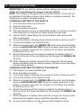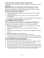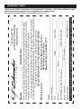
1
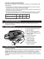
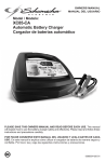
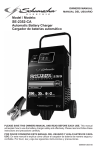
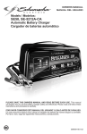
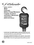
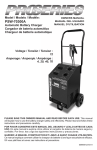
OWNERS MANUAL MANUAL DEL USUARIO ® Model / Modelo: SP3 Automatic Battery Charger/Maintainer Cargador de Baterías Automático/Mantenedor PLEASE SAVE THIS OWNERS MANUAL AND READ BEFORE EACH USE. This manual will explain how to use the charger safely and effectively. Please read and follow these instructions and precautions carefully. POR FAVOR CONSERVE ESTE MANUAL DEL USUARIO Y LEALO ANTES DE CADA USO. En este manual le explica cómo utilizar el cargador de manera segura y confiable. Por favor, lea y siga las siguientes instrucciones y precauciones. 0099001412-01 CONTENTS IMPORTANT SAFETY INSTRUCTIONS........................................................................................4 PERSONAL SAFETY PRECAUTIONS...........................................................................................5 PREPARING TO CHARGE..............................................................................................................5 CHARGER LOCATION....................................................................................................................6 DC CONNECTION PRECAUTIONS...............................................................................................6 FOLLOW THESE STEPS WHEN BATTERY IS INSTALLED IN VEHICLE.................................. 6 FOLLOW THESE STEPS WHEN BATTERY IS OUTSIDE VEHICLE.......................................... 7 GROUNDING AND AC POWER CORD CONNECTIONS ...........................................................7 ASSEMBLY INSTRUCTIONS..........................................................................................................8 FEATURES.......................................................................................................................................8 CONTROL PANEL............................................................................................................................8 OPERATING INSTRUCTIONS........................................................................................................9 DISPLAY MESSAGES...................................................................................................................12 MAINTENANCE AND CARE.........................................................................................................13 TROUBLESHOOTING...................................................................................................................13 SPECIFICATIONS..........................................................................................................................14 REPLACEMENT PARTS...............................................................................................................14 BEFORE RETURNING FOR REPAIRS........................................................................................14 LIMITED WARRANTY....................................................................................................................15 WARRANTY CARD........................................................................................................................31 CONTENIDOS INSTRUCCIONES IMPORTANTES DE SEGURIDAD................................................................16 PRECAUCIONES DE SEGURIDAD PERSONAL........................................................................17 PREPARACIÓN PARA LA CARGA ..............................................................................................18 UBICACIÓN DEL CARGADOR.....................................................................................................18 PRECAUCIONES DE CONEXIÓN EN CC...................................................................................19 SIGA ESTOS PASOS CUANDO LA BATERÍA ESTÉ COLOCADA EN EL VEHÍCULO.............19 SIGA ESTOS PASOS CUANDO LA BATERÍA SE ENCUENTRE FUERA DEL VEHÍCULO.....20 CONEXIONES A TIERRA Y ENERGÍA DE CA.............................................................................20 INSTRUCCIONES DE MONTAJE.................................................................................................21 CARACTERÍSTICAS......................................................................................................................21 PANEL DE CONTROL...................................................................................................................21 INSTRUCCIONES DE OPERACIÓN............................................................................................22 MUESTRA DE MENSAJES...........................................................................................................26 MANTENIMIENTO Y CUIDADO....................................................................................................27 LOCALIZACIÓN Y SOLUCIÓN DE PROBLEMAS.......................................................................27 ESPECIFICACIONES....................................................................................................................28 REPUESTOS..................................................................................................................................28 ANTES DE DEVOLVER A REPARACIONES...............................................................................29 GARANTÍA LIMITADA....................................................................................................................29 TARJETA DE GARANTÍA...............................................................................................................32 1. IMPORTANT SAFETY INSTRUCTIONS SAVE THESE INSTRUCTIONS. 1.1 SAVE THESE INSTRUCTIONS – This manual contains important safety and operating instructions. 1.2 Do not expose the charger to rain or snow. 1.3 Use of an attachment not recommended or sold by Schumacher® Electric Corporation may result in a risk of fire, electric shock or injury to persons. 1.4 To reduce the risk of damage to electric plug and cord, pull by the plug rather than the cord when disconnecting charger. 1.5 An extension cord should not be used unless absolutely necessary. Use of improper extension cord could result in a risk of fire and electric shock. If an extension cord must be used, make sure: •That the pins on plug of extension cord are the same number, size and shape as those of plug on charger. •That extension cord is properly wired and in good electrical condition; and •That wire size is large enough for AC ampere rating of charger, as specified in section 8. 1.6 Do not operate charger with damaged cord or plug – replace the cord or plug immediately. 1.7 Do not operate charger if it has received a sharp blow, been dropped, or otherwise damaged in any way; take it to a qualified serviceman. 1.8 Do not disassemble charger; take it to a qualified serviceman when service or repair is required. Incorrect reassembly may result in a risk of electric shock or fire. 1.9 To reduce risk of electric shock, unplug charger from outlet before attempting any maintenance or cleaning. Turning off controls will not reduce this risk. 1.10 WARNING: RISK OF EXPLOSIVE GASES. a.WORKING IN VICINITY OF A LEAD-ACID BATTERY IS DANGEROUS. BATTERIES GENERATE EXPLOSIVE GASES DURING NORMAL BATTERY OPERATION. FOR THIS REASON, IT IS OF UTMOST IMPORTANCE THAT YOU FOLLOW THE INSTRUCTIONS EACH TIME YOU USE THE CHARGER. b.To reduce risk of battery explosion, follow these instructions and those published by battery manufacturer and manufacturer of any equipment you intend to use in vicinity of battery. 1.11 Pursuant to California Proposition 65, this product contains chemicals known to the State of California to cause cancer and birth defects or other reproductive harm. Wash hands after handling. •4• 2. PERSONAL SAFETY PRECAUTIONS 2.1 Consider having someone close enough by to come to your aid when you work near a lead-acid battery. 2.2 Have plenty of fresh water and soap nearby in case battery acid contacts skin, clothing, or eyes. 2.3 Wear complete eye protection and clothing protection. Avoid touching eyes while working near battery. 2.4 If battery acid contacts skin or clothing, wash immediately with soap and water. If acid enters eye, immediately flood eye with running cold water for at least 10 minutes and get medical attention immediately. 2.5 NEVER smoke or allow a spark or flame in vicinity of battery or engine. 2.6 Be extra cautious to reduce risk of dropping a metal tool onto battery. It might spark or short-circuit battery or other electrical part that may cause explosion. 2.7 Remove personal metal items such as rings, bracelets, necklaces, and watches when working with a lead-acid battery. A lead-acid battery can produce a short-circuit current high enough to weld a ring or the like to metal, causing a severe burn. 2.8 Use the charger for charging only 6 and 12V LEAD-ACID, GEL and AGMtype rechargeable batteries with recommended rated capacities of 12Ah (6V) and 12-59Ah (12V). It is not intended to supply power to a low voltage electrical system other than in a starter-motor application. Do not use battery charger for charging dry-cell batteries that are commonly used with home appliances. These batteries may burst and cause injury to persons and damage to property. 2.9 NEVER charge a frozen battery. 3. PREPARING TO CHARGE 3.1 If necessary to remove battery from vehicle to charge, always remove grounded terminal from battery first. Make sure all accessories in the vehicle are off, so as not to cause an arc. 3.2 Be sure area around battery is well ventilated while battery is being charged. 3.3 Clean battery terminals. Be careful to keep corrosion from coming in contact with eyes. 3.4 Add distilled water in each cell until battery acid reaches level specified by battery manufacturer. Do not overfill. For a battery without removable cell caps, such as valve regulated lead acid batteries, carefully follow manufacturer’s recharging instructions. 3.5 Study all battery manufacturer’s specific precautions while charging and recommended rates of charge. 3.6 Determine voltage of battery by referring to car owner’s manual and make sure that output voltage selector switch is set at correct voltage. If charger has adjustable charge rate, charge battery initially at lowest rate. •5• 4. CHARGER LOCATION 4.1 Locate charger as far away from battery as DC cables permit. 4.2 Never place charger directly above battery being charged; gases from battery will corrode and damage charger. 4.3 Never allow battery acid to drip on charger when reading electrolyte specific gravity or filling battery. 4.4 Do not operate charger in a closed-in area or restrict ventilation in any way. 4.5 Do not set a battery on top of charger. 5. DC CONNECTION PRECAUTIONS 5.1 Connect and disconnect DC output clips only after setting any charger switches to “off” position and removing AC cord from electric outlet. Never allow clips to touch each other. 5.2 Attach clips to battery and chassis, as indicated in the sections 6 and 7. 6. 6.1 6.2 6.3 6.4 6.5 6.6 6.7 6.8 FOLLOW THESE STEPS WHEN BATTERY IS INSTALLED IN VEHICLE A SPARK NEAR THE BATTERY MAY CAUSE A BATTERY EXPLOSION. TO REDUCE THE RISK OF A SPARK NEAR THE BATTERY: Position AC and DC cords to reduce risk of damage by hood, door, or moving engine part. Stay clear of fan blades, belts, pulleys, and other parts that can cause injury to persons. Check polarity of battery posts. POSITIVE (POS, P, +) battery post usually has larger diameter than NEGATIVE (NEG, N,–) post. Determine which post of battery is grounded (connected) to the chassis. If negative post is grounded to chassis (as in most vehicles), see (6.5). If positive post is grounded to the chassis, see (6.6). For negative-grounded vehicle, connect POSITIVE (RED) clip from battery charger to POSITIVE (POS, P, +) ungrounded post of battery. Connect NEGATIVE (BLACK) clip to vehicle chassis or engine block away from battery. Do not connect clip to carburetor, fuel lines, or sheet-metal body parts. Connect to a heavy gage metal part of the frame or engine block. For positive-grounded vehicle, connect NEGATIVE (BLACK) clip from battery charger to NEGATIVE (NEG, N, –) ungrounded post of battery. Connect POSITIVE (RED) clip to vehicle chassis or engine block away from battery. Do not connect clip to carburetor, fuel lines, or sheet-metal body parts. Connect to a heavy gage metal part of the frame or engine block. When disconnecting charger, turn switches to off, disconnect AC cord, remove clip from vehicle chassis, and then remove clip from battery terminal. See Operating Instructions for length of charge information. •6• 7. 7.1 7.2 7.3 7.4 7.5 7.6 7.7 8. FOLLOW THESE STEPS WHEN BATTERY IS OUTSIDE VEHICLE A SPARK NEAR THE BATTERY MAY CAUSE A BATTERY EXPLOSION. TO REDUCE THE RISK OF A SPARK NEAR THE BATTERY: Check polarity of battery posts. POSITIVE (POS, P, +) battery post usually has a larger diameter than NEGATIVE (NEG, N, –) post. Attach at least a 24-inch-long 6-gauge (AWG) insulated battery cable to NEGATIVE (NEG, N, –) battery post. Connect POSITIVE (RED) charger clip to POSITIVE (POS, P, +) post of battery. Position yourself and free end of cable as far away from battery as possible – then connect NEGATIVE (BLACK) charger clip to free end of cable. Do not face battery when making final connection. When disconnecting charger, always do so in reverse sequence of connecting procedure and break first connection while as far away from battery as practical. A marine (boat) battery must be removed and charged on shore. To charge it on board requires equipment specially designed for marine use. GROUNDING AND AC POWER CORD CONNECTIONS This battery charger is for use on a nominal 120 volt circuit. The plug must be plugged into an outlet that is properly installed and grounded in accordance with all local codes and ordinances. The plug pins must fit the receptacle (outlet). Do not use with an ungrounded system. DANGER: Never alter the AC cord or plug provided – if it does not fit the outlet, have a proper grounded outlet installed by a qualified electrician. An improper connection can result in a risk of an electric shock or electrocution. NOTE: Pursuant to Canadian Regulations, use of an adapter plug is not allowed in Canada. Use of an adapter plug in the United States is not recommended and should not be used. USING AN EXTENSION CORD The use of an extension cord is not recommended. If you must use an extension cord, follow these guidelines: •Pins on plug of extension cord must be the same number, size, and shape as those of plug on charger. •Ensure that the extension cord is properly wired and in good electrical condition. •Wire size must be large enough for the AC ampere rating of charger, as specified below: Length of cord (feet) 25 50 100 150 AWG* size of cord 18 18 16 14 *AWG-American Wire Gauge •7• 9. ASSEMBLY INSTRUCTIONS 9.1 Remove all cord wraps and uncoil the cables prior to using the battery charger. 10. FEATURES 2 4 3 5 1 6 7 8 1.AC Power cord 2.Digital display 3.Display/ON button 4.Charging/Charged/ Maintaining LED indicator 5.Hook attachment 6.12V accessory plug quick-connect 7.Battery clamp quick-connect 8.Ring terminal quick-connect 11. CONTROL PANEL DIGITAL DISPLAY The digital display indicates the status of the battery and charger. See the Display Messages section for a complete list of messages. NOTE: During charging, the display will go into sleep mode and will not display any messages. To turn the display back on, press the display button. DISPLAY/ON BUTTON The digital display will show the battery’s voltage and percentage of charge. Press the display button to show the charge progress. LED DISPLAY GREEN LED solid (CHARGING): The charger is charging the battery. GREEN LED pulsing (CHARGED/MAINTAINING): The battery is fully charged and the charger is in maintain mode. GREEN LED flashing: The charge has aborted (see Aborted Charge section). •8• 12. OPERATING INSTRUCTIONS IMPORTANT: Do not start the vehicle with the charger connected to the AC outlet, or it may damage the charger and your vehicle. NOTE: This charger is equipped with an auto-start feature. Current will not be supplied to the battery clamps until a battery is properly connected. The clamps will not spark if touched together. CHARGING A BATTERY IN THE VEHICLE 1. Turn off all the vehicle’s accessories. 2. Keep the hood open. 3. Clean the battery terminals. 4. Place the charger on a dry, non-flammable surface, or use the convenient hook attachment to hang the unit safely outside the work area. 5. Lay the AC/DC cables away from any fan blades, belts, pulleys and other moving parts. 6. Connect the battery, following the precautions listed in sections 6 and 7. 7. Connect the charger to an electrical outlet. 8. When the charger starts, the GREEN LED will be solid, and the display will show ANALYZING BATTERY while the charger determines that the battery is properly connected, the condition of the battery, and whether the battery is 6V or 12V. 9. Monitor the progress of the charge by pressing the display button on the front of the unit. When the battery is fully charged, the GREEN LED will pulse. 10. When charging is complete, disconnect the charger from the AC power, remove the clamps from the vehicle’s chassis, and then remove the clamp from the battery terminal. CHARGING A BATTERY OUTSIDE OF THE VEHICLE 1. Place battery in a well-ventilated area. 2. Clean the battery terminals. 3. Connect the battery, following the precautions listed in sections 6 and 7. 4. Connect the charger to the electrical outlet. 5. When the charger starts, the GREEN LED will be solid, and the display will show ANALYZING BATTERY while the charger determines if the battery is properly connected, the condition of the battery, and whether the battery is 6V or 12V. 6. Monitor the progress of the charge by pressing the display button on the front of the unit. When the battery is fully charged, the GREEN LED will pulse. 7. When charging is complete, disconnect the charger from the AC power, disconnect the negative clamp, and finally the positive clamp. 8. A marine (boat) battery must be removed and charged on shore. •9• USING THE QUICK-CONNECT CABLE CONNECTORS Connect any of the three output cable assemblies to the charger in a matter of seconds. IMPORTANT: Never connect the clamp and ring terminal connectors together for use in other applications, such as external battery or other power source charging, or to extend the output cable length, as reverse polarity and/or overcharge conditions will occur. BATTERY CLAMP QUICK-CONNECT 1. Connect the end of the charger output cable to the end of the battery clamp quick-connect. 2. Follow the steps in previous sections to connect the output clamps to the battery. 3. After a good electrical connection is made to the battery, plug the power cord into a grounded 120V AC electrical wall outlet. RING TERMINAL QUICK-CONNECT The ring connectors permanently attach to the battery, providing easy access to quickly connect the charger to your battery. This application is appropriate for motorcycles, lawn tractors, ATVs and snowmobiles. 1. To permanently attach to a battery, loosen and remove each nut from the bolt at the battery terminal. 2. Connect the red POSITIVE connector ring to the POSITIVE battery terminal. 3. Connect the black NEGATIVE connector ring to the NEGATIVE battery terminal. 4. Replace and tighten the nuts to secure. 5. Connect the cable to the end of the charger output cord. Take care to keep the wires and plug away from metal and moving parts. 6. Plug the charger power cord into a grounded 120V AC electrical wall outlet. 12V ACCESSORY PLUG QUICK-CONNECT Charge or maintain your battery without lifting the hood. 1. Connect the end of the 12V accessory plug quick-connect to the charger. 2. Insert the 12V accessory plug into the 12V accessory outlet. 3. Route the power cord from the charger through the vehicle’s open window. 4. Plug the charger power cord into a grounded 120V AC electrical wall outlet. 5. If the vehicle’s ignition key has to be on in order for the accessory outlet to supply/receive power, turn the key, without starting the engine. • 10 • BATTERY CHARGING TIMES CCA = Cold Cranking Amps RC = Reserve Capacity Ah = Amp Hour NR = Not Recommended BATTERY SIZE/RATING SMALL BATTERIES Motorcycle, garden tractor, etc. 200-315 CCA CARS AND TRUCKS 315-550 CCA 550-1000 CCA MARINE/DEEP-CYCLE 6-12 Ah 12-32 Ah 40-60 RC 60-85 RC 85-190 RC 80 RC 140 RC 160 RC 180 RC CHARGE TIME (3A) 1½-2½ h 2½-7 h 7½-9½ h 9½-12 h 12-23 h 12 h 18 h 20 h 22 h Times are based on a 50% discharged battery and may change, depending on age and condition of battery. AUTOMATIC CHARGING MODE When an automatic charge is performed, the charger switches to the maintain mode automatically after the battery is charged. BATTERY CONNECTION INDICATOR If the charger does not detect a properly connected battery, charging will not start and the digital display will show one of two messages. If the display shows CONNECT CLAMPS, make sure the charger is connected to the battery and the connection points are clean and making a good connection. If the display shows WARNING CLAMPS REVERSED, unplug the charger from the AC outlet, reverse the connections at the battery, and then plug the charger back in. CHARGE COMPLETION AND MAINTAIN MODE (FLOAT MODE MONITORING) Charge completion is indicated by the GREEN LED pulsing and the digital display showing FULLY CHARGED AUTO MAINTAINING. This means that the charger has stopped charging and has switched to the Maintain Mode of operation. NOTE: If the charger has to provide its maximum maintain current for a continuous 12 hour period, it will go into Abort Mode (see Aborted Charge section). This is usually caused by a drain on the battery, or the battery could be bad. Make sure there are no loads on the battery. If there are, remove them. If there are none, have the battery checked or replaced. MAINTAINING A BATTERY The SP3 maintains both 6 and 12 volt batteries, keeping them at full charge. It is not recommended for industrial applications. NOTE: The maintain mode technology allows you to safely charge and maintain a healthy battery for extended periods of time. However, problems with the battery, electrical problems in the vehicle, improper connections or • 11 • other unanticipated conditions could cause excessive current draws. As such, occasionally monitoring your battery and the charging process is required. DESULFATION MODE If the battery is left discharged for an extended period of time, it could become sulfated and not accept a normal charge. If the charger detects a sulfated battery, the charger will switch to a special mode of operation designed for such batteries. If successful, normal charging will resume after the battery is desulfated. Desulfation could take up to 8 hours. If desulfation fails, charging will abort, the GREEN LED will flash, and the display will show CHARGE ABORTED-BAD BATTERY. ABORTED CHARGE If charging cannot be completed normally, charging will abort. When charging aborts, the charger’s output is shut off, the GREEN LED will flash, and the display will show CHARGE ABORTED-BAD BATTERY. To reset after an aborted charge, unplug the charger from the outlet, wait a few moments and plug it back in. 13. DISPLAY MESSAGES CONNECT CLAMPS (No LED lit) – Plugged into the AC outlet without the clamps connected to a battery. WARNING CLAMPS REVERSED (No LED lit) – Plugged into the AC outlet and the clamps are connected backwards to a 6V or 12V battery. ANALYZING BATTERY (Green LED lit) – Plugged into the AC outlet, and when first connected to a 6V or 12V battery correctly. CHARGING 12V – XX% (Green LED lit) – Plugged into the AC outlet and correctly connected to a discharged 12V battery. CHARGING 6V – XX% (Green LED lit) – Plugged into the AC outlet and correctly connected to a discharged 6V battery. FULLY CHARGED AUTO MAINTAINING (Green LED pulsing) – Plugged into the AC outlet and correctly connected to a fully charged 6V or 12V battery. CHARGE ABORTED-BAD BATTERY (Green LED flashing) – Circumstances that could cause an Abort situation during charging: •The battery is severely sulfated or has a shorted cell and can’t reach a full charge. •The battery is too large or there is a bank of batteries and it doesn’t reach full charge within a set time period. Circumstances that could cause an Abort situation during maintain: •The battery is severely sulfated or has a weak cell and will not hold a charge. •There is a large draw on the battery and the charger has to supply its maximum maintain current for a 12 hour period to keep the battery at full charge. • 12 • 14. MAINTENANCE AND CARE A minimal amount of care can keep your battery charger working properly for years. •Clean the clamps each time you are finished charging. Wipe off any battery fluid that may have come in contact with the clamps, to prevent corrosion. •Occasionally cleaning the case of the charger with a soft cloth will keep the finish shiny and help prevent corrosion. •Coil the input and output cords neatly when storing the charger. This will help prevent accidental damage to the cords and charger. •Store the charger unplugged from the AC power outlet in an upright position. •Store inside, in a cool, dry place. Do not store the clamps clipped together, on or around metal, or clipped to the cables. 15. TROUBLESHOOTING PROBLEM POSSIBLE CAUSE Battery clamps do not spark when touched together. The charger is equipped with an auto-start feature. It will not supply current to the battery clamps until a battery is properly connected. The clamps will not spark if touched together. No problem; this is a normal condition. The charger will not turn on when properly connected. AC outlet is dead. Check for open fuse or circuit breaker supplying AC outlet. Poor electrical connection. Check power cord and extension cord for loose fitting plug. I cannot select a 6V or The charger is equipped 12V setting. with Auto Voltage Detection, which automatically detects the voltage and charges the battery. • 13 • REASON/SOLUTION No problem; this is normal. PROBLEM POSSIBLE CAUSE REASON/SOLUTION Green LED is solid and the display shows ANALYZING BATTERY. The charger needs to check the condition of the battery. The Green LED will be solid when the charger is checking the condition of the battery. This is normal. Green LED is flashing and the display shows CHARGE ABORTEDBAD BATTERY. The battery is sulfated. Reset the charger by briefly unplugging it. The battery is too large for the charger. You need a charger with a higher amp rate. The display shows CONNECT CLAMPS. The clamps are not making Check for poor connection a good connection. at battery and frame. The fuse is bad. Replace the in-line fuse for the ring connector. 16. SPECIFICATIONS Input Voltage........................................................ 120V AC @ 60Hz, 0.91A Output Voltage............................... 6V or 12V, with Auto Voltage Detection Output Current Rating.................................................. 2A @ 6V; 3A @12V 17. REPLACEMENT PARTS Battery clamps (quick-connect)...............................................3899002636 Ring connectors (quick-connect) ............................................2299002042 12V accessory plug (quick-connect)........................................3899001401 18. BEFORE RETURNING FOR REPAIRS For information about troubleshooting, contact customer service for assistance: [email protected] www.batterychargers.com or call 1-800-621-5485, Monday-Friday 7:00am to 5:00pm CST For REPAIR OR RETURN, contact Customer Service at 1-800-621-5485. DO NOT SHIP UNIT until you receive a RETURN MERCHANDISE AUTHORIZATION (RMA) number from Customer Service at Schumacher Electric Corporation. • 14 • 19. LIMITED WARRANTY WARRANTY NOT VALID IN MEXICO. SCHUMACHER ELECTRIC CORPORATION, 801 BUSINESS CENTER DRIVE, MOUNT PROSPECT, IL 60056-2179, MAKES THIS LIMITED WARRANTY TO THE ORIGINAL RETAIL PURCHASER OF THIS PRODUCT. THIS LIMITED WARRANTY IS NOT TRANSFERABLE OR ASSIGNABLE. Schumacher Electric Corporation (the “Manufacturer”) warrants this charger for five (5) years from the date of purchase at retail against defective material or workmanship that may occur under normal use and care. If your unit is not free from defective material or workmanship, Manufacturer’s obligation under this warranty is solely to repair or replace your product with a new or reconditioned unit at the option of the Manufacturer. It is the obligation of the purchaser to forward the unit, along with proof of purchase and mailing charges prepaid to the Manufacturer or its authorized representatives in order for repair or replacement to occur. Manufacturer does not provide any warranty for any accessories used with this product that are not manufactured by Schumacher Electric Corporation and approved for use with this product. This Limited Warranty is void if the product is misused, subjected to careless handling, repaired, or modified by anyone other than Manufacturer or if this unit is resold through an unauthorized retailer. Manufacturer makes no other warranties, including, but not limited to, express, implied or statutory warranties, including without limitation, any implied warranty of merchantability or implied warranty of fitness for a particular purpose. Further, Manufacturer shall not be liable for any incidental, special or consequential damage claims incurred by purchasers, users or others associated with this product, including, but not limited to, lost profits, revenues, anticipated sales, business opportunities, goodwill, business interruption and any other injury or damage. Any and all such warranties, other than the limited warranty included herein, are hereby expressly disclaimed and excluded. Some states do not allow the exclusion or limitation of incidental or consequential damages or length of implied warranty, so the above limitations or exclusions may not apply to you. This warranty gives you specific legal rights and it is possible you may have other rights which vary from this warranty. THIS LIMITED WARRANTY IS THE ONLY EXPRESS LIMITED WARRANTY AND THE MANUFACTURER NEITHER ASSUMES OR AUTHORIZES ANYONE TO ASSUME OR MAKE ANY OTHER OBLIGATION TOWARDS THE PRODUCT OTHER THAN THIS WARRANTY. Schumacher® and the Schumacher Logo are registered trademarks of Schumacher Electric Corporation. Battery Extender® is a trademark of Auto Meter Products, Inc. • 15 • 1. INSTRUCCIONES IMPORTANTES DE SEGURIDAD GUARDE ESTAS INSTRUCCIONES. 1.1 GUARDE ESTAS INSTRUCCIONES – Este manual contiene instrucciones operativas y de seguridad de importancia. 1.2 No exponga el cargador a la lluvia o a la nieve. 1.3 El uso de un accesorio no recomendado o suministrado por Schumacher® Electric Corporation puede provocar riesgo de incendio, descarga eléctrica o lesiones a personas. 1.4 Para reducir el riesgo de daños al enchufe o cable eléctrico, jale del enchufe en lugar de jalar del cable al desconectar el cargador. 1.5 No se debe utilizar un alargador a menos que resulte absolutamente necesario. El uso de un alargador inadecuado puede provocar riesgo de incendio o descarga eléctrica. En caso de que deba utilizarse un alargador, asegúrese de que: •Los pasadores en el enchufe del alargador posean el mismo número, tamaño y forma que aquellos presentes en el enchufe del cargador. •El alargador se encuentre correctamente conectado y en buenas condiciones eléctricas; y •El tamaño del cable sea lo suficientemente extenso para el amperaje en CA del cargador como se especifica en sección 8. 1.6 No utilice el cargador si el mismo posee un enchufe o cable dañado; substituya el cable o el enchufe inmediatamente por una persona calificada en el ramo. 1.7 No utilice el cargador si el mismo recibió un golpe fuerte, si se cayó o si sufrió daños de cualquier otra forma; hágalo revisar por una persona capacitada que efectúe reparaciones. 1.8 No desarme el cargador; hágalo revisar por una persona capacitada que efectúe reparaciones cuando necesite servicio de mantenimiento o una reparación. Volver a ensamblar el cargador en forma incorrecta puede provocar riesgo de incendio o descarga eléctrica. 1.9 Para reducir el riesgo de descarga eléctrica, desenchufe el cargador del tomacorriente antes de intentar llevar a cabo cualquier actividad de mantenimiento o limpieza. El simple apagado de los controles no reducirá este riesgo. 1.10 ADVERTENCIA: RIESGO DE GASES EXPLOSIVOS. a.RESULTA PELIGROSO TRABAJAR EN FORMA CERCANA A UNA BATERÍA DE PLOMO. LAS BATERÍAS GENERAN GASES EXPLOSIVOS DURANTE SU NORMAL FUNCIONAMIENTO. POR ESTE MOTIVO, RESULTA DE SUMA IMPORTANCIA QUE SIGA LAS INSTRUCCIONES CADA VEZ QUE UTILIZA EL CARGADOR. • 16 • b.Para reducir el riesgo de explosión de una batería, siga estas instrucciones y aquellas publicadas por el fabricante de la batería y por el fabricante de cualquier equipo que intente utilizar en la proximidad de la batería. Revise las pautas de precaución en estos productos y en el motor. 1.11 Conforme a la Propuesta 65 de California, este producto contiene químicos de los cuales en el Estado de California se tiene conocimiento que provocan cáncer y malformaciones congénitas u otras lesiones reproductivas. Lávese las manos después de usar. 2. PRECAUCIONES DE SEGURIDAD PERSONAL 2.1 Considere la idea de que alguna persona se encuentre cerca suyo para poder ayudarlo cuando trabaje en forma cercana a una batería de plomo-ácido. 2.2 Cuente con una gran cantidad de agua potable y jabón a mano en caso de que el ácido de la batería tenga contacto con su piel, ropa u ojos. 2.3 Utilice protección visual y corporal completa, incluyendo gafas de seguridad y prendas de protección. Evite tocar sus ojos mientras trabaje en forma cercana a la batería. 2.4 Si el ácido de la batería tiene contacto con su piel o su ropa, lave de inmediato el área afectada con agua y jabón. En caso de que ingrese ácido en un ojo, sumerja el mismo de inmediato bajo agua potable corriente por al menos 10 minutos y obtenga atención médica en forma inmediata. 2.5 NUNCA fume o permita la presencia de chispas o llamas en la proximidad de una batería o motor. 2.6 Tenga especial cuidado para reducir el riesgo de dejar caer una herramienta de metal sobre la batería. Esto podría provocar chispas o un cortocircuito en la batería o en cualquier otra pieza eléctrica que podría provocar una explosión. 2.7 No utilice elementos personales de metal tales como anillos, pulseras, collares y relojes al trabajar con una batería de plomo-ácido. Una batería de plomo-ácido puede producir una corriente de cortocircuito lo suficientemente elevada como para soldar un anillo o provocar efectos similares sobre el metal, causando una quemadura de gravedad. 2.8 Utilice el cargador de la batería, en baterías recargables de 6 y 12V de plomo-ácido, GEL y tipo AGM, con recomienda usar capacidad de la batería de 12Ah (6V) y 12-59Ah (12V). Este cargador no está destinado a suministrar energía a sistemas eléctricos de baja tensión más que en una aplicación de un motor de arranque. No utilice este cargador de batería para cargar baterías de pila seca que por lo general se utilizan con artefactos domésticos. Estas baterías podrían explotar y provocar lesiones a personas o daño a la propiedad. 2.9 NUNCA cargue una batería congelada. • 17 • 3. PREPARACIÓN PARA LA CARGA 3.1 Si resulta necesario extraer la batería del vehículo para cargarla, siempre retire el terminal con descarga a tierra en primer lugar. Asegúrese de que todos los accesorios en el vehículo se encuentren apagados para evitar la formación de arcos eléctricos. 3.2 Asegúrese de que el área que rodea a la batería se encuentre bien ventilada mientras se carga la batería. 3.3 Limpie los terminales de la batería antes de cargar la batería. Durante la limpieza, evite que la corrosión producida por aire tenga contacto con sus ojos. 3.4 Agregue agua destilada a cada pila hasta que el ácido de la batería alcance el nivel especificado por el fabricante de la batería. No provoque derrames. En lo que concierne a baterías que no cuentan con tapas extraíbles para pilas, tales como baterías de plomo-ácido reguladas por válvulas (VRLA, por sus siglas en inglés), siga cuidadosamente las instrucciones de recarga del fabricante. 3.5 Lea, comprenda y siga todas las instrucciones para el cargador, la batería, el vehículo y cualquier equipo que se utilice cerca de la batería y el cargador. Controle todas las precauciones específicas establecidas por el fabricante de la batería al realizar la carga, así también como los índices de carga recomendados. 3.6 Determine la tensión de la batería al consultar el manual del usuario del vehículo y asegúrese de que el interruptor de selección de la tensión de salida se encuentre establecido en la tensión correcta (en su caso). Si el cargador posee un índice de carga ajustable, cargue la batería en el menor índice en primer lugar. 4. UBICACIÓN DEL CARGADOR 4.1 Ubique el cargador a la mayor distancia posible de la batería como lo permitan los cables de CC. 4.2 Nunca ubique el cargador directamente por encima de la batería que se carga; los gases de la batería corroerán y dañarán el cargador. 4.3 Nunca permita que el ácido de la batería gotee sobre el cargador al leer el peso específico del electrolito o al cargar la batería. 4.4 No utilice el cargador en un área cerrada o restrinja la ventilación en cualquier forma. 4.5 No ubique la batería encima del cargador. • 18 • 5. PRECAUCIONES DE CONEXIÓN EN CC 5.1 Conecte y desconecte las pinzas de salida CC. sólo después de haber establecido todos los interruptores del cargador a la posición de “apagado” (si es aplicable) y de haber desconectado el enchufe de C.A. del tomacorriente eléctrico. Nunca permita que las pinzas tengan contacto entre sí. 5.2 Sujete las pinzas a la batería y al chasis, como se indica en en las secciones 6 y 7. 6. 6.1 6.2 6.3 6.4 6.5 6.6 6.7 6.8 SIGA ESTOS PASOS CUANDO LA BATERÍA ESTÉ COLOCADA EN EL VEHÍCULO UNA CHISPA PROVOCADA CERCA DE LA BATERÍA PUEDE CAUSAR LA EXPLOSIÓN DE LA BATERÍA. PARA REDUCIR EL RIESGO DE PROVOCAR CHISPAS CERCA DE LA BATERÍA: Ubique los cables de C.A. y C.C. para reducir el riesgo de daños a la cubierta, a la puerta y a las piezas móviles o calientes del motor. Manténgase alejado de las paletas del ventilador, correas, poleas y otras piezas que podrían provocar lesiones. Verifique la polaridad de los bornes de la batería. El borne POSITIVO (POS, P, +) de la batería generalmente posee un diámetro mayor al borne NEGATIVO (NEG, N, -). Determine qué borne de la batería hace descarga a tierra (se encuentra conectado) con el chasis. Si el borne negativo hace descarga a tierra con el chasis (como en la mayor parte de los vehículos), ver el paso (5.) Si el borne positivo hace descarga a tierra con el chasis, ver el paso (6.). En un vehículo con descarga a tierra por borne negativo, conecte el gancho POSITIVO (ROJO) del cargador de batería al borne POSITIVO (POS, P, +) sin descarga a tierra de la batería. Conecte el gancho NEGATIVO (NEGRO) al chasis del vehículo o al bloque motor alejado de la batería. No conecte el gancho al carburador, líneas de combustible o cuerpos metálicos. Conecte a una pieza metálica de calibre grueso del marco o del bloque motor. En un vehículo con descarga a tierra por borne positivo, conecte el gancho NEGATIVO (NEGRO) del cargador de batería al borne NEGATIVO (NEG, N, -) sin descarga a tierra de la batería. Conecte el gancho POSITIVO (ROJO) al chasis del vehículo o al bloque motor alejado de la batería. No conecte al carburador, líneas de combustible o cuerpos metálicos. Conecte a una pieza metálica de calibre grueso del marco o del bloque motor. Al desconectar el cargador, apague todos los interruptores (en su caso), desconecte el cable de C.A., retire el gancho del chasis del vehículo y luego retire el gancho del terminal perteneciente a la batería. Vea Instrucciones de Operación para duración de la carga. • 19 • 7. 7.1 7.2 7.3 7.4 7.5 7.6 7.7 8. SIGA ESTOS PASOS CUANDO LA BATERÍA SE ENCUENTRE FUERA DEL VEHÍCULO UNA CHISPA PROVOCADA CERCA DE LA BATERÍA PUEDE CAUSAR LA EXPLOSIÓN DE LA BATERÍA. PARA REDUCIR EL RIESGO DE PROVOCAR CHISPAS CERCA DE LA BATERÍA: Verifique la polaridad de los bornes de la batería. El borne POSITIVO (POS, P, +) de la batería generalmente posee un diámetro mayor al borne NEGATIVO (NEG, N, -). Sujete al menos un cable aislado de batería de 24 pulgadas (61 cm) de largo con calibre 6 según el Calibre americano de cables (AWG, por sus siglas en inglés) al borne NEGATIVO (NEG, N, -) de la batería. Conecte el gancho POSITIVO (ROJO) del cargador al borne POSITIVO (POS, P, +) de la batería. Ubíquese junto con el extremo libre del cable que previamente sujetó al borne NEGATIVO (NEG, N, -) de la batería a la mayor distancia posible de la batería. Luego conecte el gancho NEGATIVO (NEGRO) del cargador al extremo libre del cable. No se ubique en posición frontal a la batería al realizar la conexión final. Al desconectar el cargador, siempre hágalo en forma inversa al procedimiento de conexión y realice la primera conexión tan lejos de la batería como sea posible. Una batería marina (para barcos) se debe retirar y cargar en tierra. Para realizar una carga a bordo se necesitan equipamientos especialmente diseñados para uso marino. CONEXIONES A TIERRA Y ENERGÍA DE CA Este cargador de batería está destinado a un uso en un circuito con tensión nominal de 120 V. El enchufe se debe conectar a un tomacorriente adecuadamente instalado y que cuente con descarga a tierra de acuerdo con todas las ordenanzas y códigos. Los pasadores del enchufe deben adaptarse al receptáculo (tomacorriente). No utilizar con un sistema que no posea descarga a tierra. PELIGRO: Nunca altere el cable o enchufe de C.A. suministrado, si no se ajusta al tomacorriente, haga instalar un tomacorriente adecuado con descarga a tierra por medio de un electricista capacitado. Una conexión inadecuada puede provocar un riesgo de descarga eléctrica o electrocución. NOTA: De acuerdo a las Leyes Canadienses, el uso de un enchufe adaptador no es permitido en el Canada. El uso de un enchufe como adaptador no se recomienda y no debe ser utilizado Estados Unidos. • 20 • USO DE UN CABLE DE EXTENSIÓN El uso de una extensión no se recomienda. Si debe usar una extensión, siga estas pautas: •Las clavijas del enchufe del cable de extensión debe ser el mismo número, tamaño y forma que las del enchufe del cargador. •Asegúrese de que el cable de extensión esté conectado correctamente y en buenas condiciones eléctricas. •El tamaño del cable debe ser lo suficientemente extenso para el calibre de amperios del cargador de CA, como se especifica a continuación: Longitud del cable (pies) 25 50 100 150 Calibre del cable AWG* 18 18 16 14 *AWG-American Wire Gauge 9. INSTRUCCIONES DE MONTAJE 9.1 Desenrede todos los cordones y extienda los cables antes de usar el cargador de baterías. 10. CARACTERÍSTICAS 2 4 3 5 1 7 8 1. Cable de alimentación de CA 2. Pantalla digital 3. Botón de pantalla digital/ON 4. Carga/Cargado/Mantenimiento indicator LED 6 5. Accesorio de gancho 6. Conector de 12V (conexión rápida) 7. Pinzas de batería (conexión rápida) 8. Conectores de argolla (conexión rápida) 11. PANEL DE CONTROL PANTALLA DIGITAL La pantalla digital indica la condición de la batería y el cargador. Vea la sección de Muestra de Mensajes para obtener una lista completa de los mensajes. NOTA: Durante la carga, la pantalla entra en el modo de suspensión y no se mostrará cualquiera mensaje. Para activar la pantalla, pulse el botón de pantalla. • 21 • BOTÓN DE PANTALLA/ON La pantalla digital mostrará el voltaje y el porcentaje de carga de la batería. Pulse el botón de pantalla para mostrar el progreso de carga. PANTALLA LED LED VERDE sólido (CARGA): El cargador está cargando la batería. LED VERDE pulsante (CARGADA/MANTENIMIENTO): La carga de la batería está completa y que el cargador cambió a modo mantener. LED VERDE intermitente: La carga ha anulado (ver sección de carga anulada). 12. INSTRUCCIONES DE OPERACIÓN IMPORTANTE: No arranque el vehículo con el cargador conectado a la toma de CA, o puede dañar el cargador y su vehículo. NOTA: Este cargador está equipado con un auto-rectificador. La corriente no llegará a las pinzas de la batería hasta que la batería esté apropiadamente conectada. Significado, las pinzas no harán corto si se juntan una con otra. CARGA DE LA BATERÍA EN EL VEHÍCULO 1. Apague todos los accesorios del vehículo. 2. Mantenga el cofre abierto. 3. Limpie las terminales de la batería. 4. Coloque el cargador sobre una superficie seca y no inflamable, o utilice el accesorio de gancho conveniente para colgar la unidad de forma segura fuera del área de trabajo. 5. Coloque los cables de CA / CC lejos de las aspas del ventilador, bandas, poleas y otras partes móviles. 6. Para un vehículo negativo a tierra (como en la mayoría de los vehículos), conecte la pinza POSITIVA (ROJO) del cargador al poste POSITIVO (POS, P, +) de la batería. A continuación, conecte la pinza NEGATIVA (NEGRO) del cargador al chasis del vehículo o bloque del motor, lejos de la batería. 7. Para un vehículo positivo-tierra, conecte la pinza de cargador NEGATIVO (NEGRO) al poste NEGATIVO (NEG, N, -) de la batería. A continuación, conecte la pinza POSITIVA (ROJO) al chasis del vehículo o bloque del motor lejos de la batería. NUNCA conecte las abrazaderas de las mangueras de combustible del carburador o de chapa de la carrocería. 8. Conecte el cargador a la toma de corriente. 9. Cuando se inicia el cargador, el LED VERDE será sólido y la pantalla mostrará ANALYZING BATTERY mientras el cargador determina si la batería está correctamente conectado, el estado de la batería y si la batería es de 6V o 12V. • 22 • 10. Monitorear el progreso de la carga pulsando el botón de pantalla de la parte delantera de la unidad. Cuando la batería está completamente cargada, el LED VERDE pulsará. 11. Cuando la carga está completa, desconecte el cargador de la alimentación de CA, retire la pinza del chasis del vehículo y quite la pinza de la terminal de la batería. CARGA DE LA BATERÍA FUERA DEL VEHÍCULO 1. Coloque la batería un área bien ventilada. 2. Limpie las terminales de la batería. 3. Conecte un cable insolado de 24 pulgadas de largo, 6 de calibre (AWG) al poste NEGATIVO (NEG, N, -) de la batería (i. e., cables) (no incluidos). 4. Conecte la pinza POSITIVA (ROJO) al poste POSITIVO (POS, P, +) de la batería. 5. Colóquese usted mismo y el cable “extensión del poste negativo” lo más lejos posible de la batería y conecte la pinza NEGATIVA (NEGRO) al extremo libre del cable. 6. Conecte el cargador a la toma de corriente. 7. Cuando se inicia el cargador, el LED VERDE será sólido y la pantalla mostrará ANALYZING BATTERY mientras el cargador determina si la batería está correctamente conectado, el estado de la batería y si la batería es de 6V o 12V. 8. Monitorear el progreso de la carga pulsando el botón de pantalla de la parte delantera de la unidad. Cuando la batería está completamente cargada, el LED VERDE pulsará. 9. Cuando la carga está completa, desconecte el cargador de la corriente AC, desconecte la pinza negativa, y por último la pinza positiva. 10. Una batería marina (de barco) se debe retirar y cargar en tierra. USO DE CONECTORES DE CABLES DE CONEXIÓN RÁPIDA Conectar cualquiera de los tres montajes de cable de salida para el cargador en cuestión de segundos. ADVERTENCIA: Nunca conecte la pinza y las terminales de los conectores de argolla juntos, para aplicarlo de otra forma, tal como batería externa u otra fuente de poder de carga, o para alargar el cable de salida, esto ocasionará polaridad invertida o sobrecarga. PINZAS DE BATERÍA CONEXIÓN RÁPIDA 1. Conecte la punta del cable de salida del cargador a la punta del cable de pinzas de la batería conexión rápida. 2. Siga los pasos expuestos en las secciones anteriores para hacer la conexión a las pinzas de la batería. 3. Después de realizar una buena conexión a la batería, conecte el cable de alimentación del cargador en una toma de corriente de 120V CA eléctrica de pared. • 23 • CONECTORES DE ARGOLLA CONEXIÓN RÁPIDA El conector de anillos se conecta en forma permanente a la batería, proporcionando un fácil acceso para conectar rápidamente el cargador a la batería. Esta aplicación es apropiada para motocicletas, los tractores de jardín, vehículos todo terreno y motos de nieve. 1. Para sujetarlos permanentemente a la batería, aflójelo y retire las tuercas del perno de los postes de la batería. 2. Conecte el conector, de argolla, rojo POSITIVO al poste POSITIVO de la batería. 3. Conecte el conector, de argolla, negro NEGATIVO al poste NEGATIVO de la batería. 4. Reajuste y apriete las tuercas para asegurar. 5. Conecte el cable a la punta del cable de salida del cargador. Asegúrese de mantener los cables y enchufe alejados de metal o partes móviles. 6. Conecte el cable de alimentación del cargador en una toma de corriente de 120V CA eléctrica de pared. CONECTOR DE 12 V CONEXIÓN RÁPIDA Cargue o mantenga su batería sin necesidad de levantar el cofre. 1. Conecte la punta del enchufe 12V accesorio al cargador. 2. Insérte el accesorio de 12 Volts a la salida del accesorio de 12 Volts. 3. Dirija el cable de corriente del cargador por la ventana abierta del vehículo. 4. Conecte el cable de alimentación del cargador en una toma de corriente de 120V CA eléctrica de pared. 5. Si la llave de arranque del vehículo tiene que estar puesta para que el accesorio suministre/recibir poder, girar la llave, sin arrancar el motor. TIEMPOS DE CARGA CCA = Amperaje de arranque en frío RC = Capacidad de reserva Ah = Amp/hora NR = No se recomiendan TAMAÑO/ÍNDICE DE LA BATERÍA TIEMPO DE CARGA (3A) 6-12 Ah 1½-2½ h BATERÍAS PEQUEÑAS Motocicleta, tractor de jardín, etc. 12-32 Ah 2½-7 h 200-315 CCA 40-60 RC 7½-9½ h AUTOS/CAMIONES 315-550 CCA 60-85 RC 9½-12 h 550-1000 CCA 85-190 RC 12-23 h 80 RC 12 h 140 RC 18 h MARINA/CICLO PROFUNDO 160 RC 20 h 180 RC 22 h Los tiempos están basados en un 50% descargada batería y pueden cambiar, dependiendo de la edad y la condición de la batería. • 24 • MODO DE CARGA AUTOMÁTICA Cuando se realiza una carga automática, el cargador cambia del maintain mode [modo de mantenimiento] (ver a continuación) automáticamente después que la batería se cargue. INDICADOR DE CONEXIÓN DE LA BATERÍA Si el cargador no detecta una batería conectada correctamente, la carga no se iniciará y la pantalla digital mostrará uno de los dos mensajes. Si la pantalla muestra CONNECT CLAMPS, asegúrese de que el cargador está conectado a la batería y las puntas de conexión están limpias y hacen una buena conexión. Si la pantalla muestra WARNING CLAMPS REVERSED, desenchufe el cargador de la toma de corriente, invierta las conexiones de la batería y luego conecte el cargador de nuevo. FINALIZACIÓN DE LA CARGA Y MODO DE MANTENIMIENTO (MONITOREO A MODO DE FLOTE) La carga completa se señala mediante el LED VERDE pulsante y la pantalla digital que muestra FULLY CHARGED AUTO MAINTAINING. Esto significa que el cargador ha dejado de cargar y ha cambiado el funcionamiento al Modo de Mantener. NOTA: Si el cargador tiene que funcionar al máximo en corriente continua de mantenimiento a un periodo de 12 horas, se transladará al modo de anulada (véase la sección Carga Anulada). Esto es ocacionalmente causado por una pérdida de energía en la batería o la batería está dañada. Asegúrese que no escape de carga en la batería y si la hay evítela, en caso contrario, verifique o reémplace la batería. MANTENIENDO UNA BATERÍA El SP3 mantiene las baterías de 6 y 12 voltios, manteniéndolas a carga completa. No se recomienda para aplicaciones industriales. NOTA: La tecnología de modo de mantenimiento le permite cargar de forma segura y mantener una batería en buen estado durante largos períodos de tiempo. Ahora, los problemas con la batería, problemas eléctricos del vehículo, conexiones equivocadas u otras condiciones que surgan, podrías causar absorsión de corriente excesiva. De modo que, se recomienda, enérgicamente supervisar la batería y el proceso de carga. MODO DE DESULFATACIÓN Si la batería está descargada por un periodo de tiempo prolongado, podría sulfatarse y no aceptar una carga normal. Si el cargador detecta una batería sulfatada, el cargador se cambiará a un modo especial de operación diseñado para este tipo de baterías. Si tiene éxito, la carga normal se reanudará después de que la batería está desulfatada. La desulfuración puede durar hasta 8 horas. Si la desulfuración falla, la carga se abortará, el LED VERDE parpadeará y la pantalla mostrará CHARGE ABORTED-BAD BATTERY. • 25 • CARGA ANULADA Si no se puede completar la carga normalmente, la carga se anulará. Cuando la carga se interrumpe, la salida del cargador se apaga, la luz LED VERDE parpadeará y la pantalla mostrará CHARGE ABORTED-BAD BATTERY. Para reajustar después de una carga rechazada, desenchufe el cargador del contacto de la CA, espere algunos minutos y luego conecte el cargador de nuevo. 13. MUESTRA DE MENSAJES CONNECT CLAMPS (no luz LED) – Conectado a la toma de CA sin las pinzas conectadas a la batería. WARNING CLAMPS REVERSED (no luz LED) – Conectado a la toma de CA y las pinzas conectadas en forma inversa a una de 6V o 12V. ANALYZING BATTERY (LED verde encendido) – Conectado a la toma de CA, y la primera vez que conecta a una batería de 6V o 12V correctamente. CHARGING 12V – XX% (LED verde encendido) – Conectado a la toma de CA y correctamente conectado a una batería de 12V descargada. CHARGING 6V – XX% (LED verde encendido) – Conectado a la toma de CA y correctamente conectado a una batería de 6V descargada. FULLY CHARGED AUTO MAINTAINING (LED verde pulsante) – Conectada a la toma de CA y correctamente conectado a una batería completamente cargada 6V o 12V. CHARGE ABORTED-BAD BATTERY (LED verde intermitente) – Las circunstancias que pueden causar una situación de abortar durante la carga: •La batería está muy sulfatada o tiene una celda en corto y no se puede alcanzar una carga completa. •La batería es demasiado grande o hay un banco de baterías y no alcanza la carga completa en un período de tiempo establecido. Las circunstancias que pueden causar una situación de abortar durante mantienen: •La batería está muy sulfatada o tiene una célula débil y no mantener la carga. •Hay un gran sorteo de la batería y el cargador tiene que suministrar su máximo mantener vigente durante un período de 12 horas para mantener la batería a plena carga. • 26 • 14. MANTENIMIENTO Y CUIDADO Con cuidados mínimos puede mantener el cargador de baterías funcionando correctamente durante años. •Limpie las pinzas cada vez que termine de usar el cargador. Limpie el fluido de la batería que podría haber estado en contacto con las pinzas para evitar la corrosión. •De vez en cuando, limpie la carcasa del cargador con un paño suave para conservar el acabado brillante y evitar la corrosión. •Enrolle los cables de entrada y salida cuidadosamente cuando almacene el cargador. Esto ayudará a evitar daños accidentales a los cables y el cargador. •Guarde el cargador desenchufado de la toma de alimentación de CA en posición vertical. •Debe conservarse en un lugar fresco y seco. No sujete las pinzas a un metal, ni las junte. 15. LOCALIZACIÓN Y SOLUCIÓN DE PROBLEMAS PROBLEMA POSIBLE CAUSA Las pinzas de la batería no hacen corto al juntarse una con otra. Este cargador está equipado con un auto-rectificador. Este no permitirá paso de corriente si las pinzas de la batería no están conectadas en forma correcta. Significado, las pinzas no harán corto si se juntan una con otra. El cargador no se enciende incluso al estar bien conectado. Tomacorriente de CA Controle la posible fuera de funcionamiento. presencia de fusibles abiertos o disyuntores que suministren energía al tomacorriente de CA. Batería defectuosa. • 27 • SOLUCIÓN No hay problema; es una condición normal. Haga revisar la batería. PROBLEMA POSIBLE CAUSA SOLUCIÓN No puedo seleccionar los 6 o 12 Voltios. El Cargador está No hay problema; es equipado con Detección una condición normal. de Auto Voltaje, que automáticamente detecta el voltaje y carga la batería. El LED verde es sólida y la pantalla muestra ANALYZING BATTERY. El cargador tiene que comprobar el estado de la batería. El LED verde parpadea y en la pantalla muestra CHARGE ABORTEDBAD BATTERY. La batería está sulfatada. Brevemente desenchufe el cargador para restablecer. La pantalla muestra CONNECT CLAMPS. Las pinzas no hacen buena conexión. Revise la conexión falsa a la batería y la carrocería. El fusible está quemado. Reemplace el fusible en línea para el conector de anillo. El LED verde será sólido cuando el cargador está comprobando el estado de la batería. Es condición normal. La batería es demasiado Usted necesita un grande para el cargador. cargador con una velocidad amperios más alta. 16. ESPECIFICACIONES Voltaje de entrada................................................ 120V AC @ 60Hz, 0,91A Salida de voltaje..........................6V o 12V, con Detección de Auto Voltaje Salida de corriente...................................................... 2A @ 6V; 3A @ 12V 17. REPUESTOS Pinzas de batería (conexión rápida)........................................3899002636 Conectores de argolla (conexión rápida) ................................2299002042 Enchufe 12V accesorio (conexión rápida)...............................3899001401 • 28 • 18. ANTES DE DEVOLVER A REPARACIONES Para obtener información sobre la solución de problemas, póngase en contacto con el departamento de servicio al cliente para recibir asistencia: [email protected] www.batterychargers.com o llame 1-800-621-5485 Lunes-viernes 7:00am to 5:00pm CST Para REPARACIÓN O DEVOLUCIÓN, comuníquese con Servicios al Cliente al 1-800-621-5485. NO ENVÍE LA UNIDAD hasta que usted reciba AUTORIZACIÓN DE DEVOLUCIÓN DE MERCANCÍA (RMA) de Servicios al Cliente de Schumacher Electric Corporation. 19. GARANTÍA LIMITADA GARANTIA LIMITADA NO VALIDA EN MEXICO. SCHUMACHER ELECTRIC CORPORATION, 801 BUSINESS CENTER DRIVE, MOUNT PROSPECT, IL 60056-2179, REALIZA LA PRESENTE GARANTÍA LIMITADA AL COMPRADOR MINORISTA ORIGINAL DE ESTE PRODUCTO. LA PRESENTE GARANTÍA LIMITADA NO PUEDE TRANSFERIRSE NI CEDERSE. Schumacher Electric Corporation (el “Fabricante”) otorga garantía por este cargador de batería por un plazo de cinco (5) años contados a partir de la fecha de compra por menor por la existencia de cualquier material o de mano de obra defectuosos que pudieran surgir por su uso y cuidado normal. Si su unidad cuenta con material defectuoso o defectos de mano de obra, la obligación de los Fabricantes, conforme a la presente garantía, será simplemente reparar o sustituir el producto por uno nuevo o por una unidad reparada, a elección del fabricante. Es obligación del comprador enviar la unidad con comprobante de compra y los gastos de envío prepagos al fabricante o a sus representantes autorizados para que ésta se pueda reparar o reemplazar. El Fabricante no presta garantía por lo accesorios utilizados con este producto que no sean los fabricados por Schumacher Electric Corporation y que no estén aprobados para su uso con este producto. La presente Garantía Limitada será nula si el producto se utiliza en forma errónea, se trata de manera inadecuada, es reparado o modificado por personas que nos sean el Fabricante o si esta unidad es revendida a través de un vendedor minorista no autorizado. • 29 • El Fabricante no realiza ninguna otra garantía, incluidas, a título enunciativo, las garantías expresas, implícitas o legales, incluidas, a modo de ejemplo, las garantías implícitas de comerciabilidad o adecuación a un fin específico. Asimismo, el Fabricante no será responsable ante reclamos por daños accidentales, especiales ni directos en los que incurran los compradores, usuarios u otras personas asociadas al producto, incluidas, a título enunciativo, los ingresos y ganancias no percibidos, ventas anticipadas, oportunidades comerciales, el buen nombre, la interrupción de la actividad comercial o cualquier otro daño que haya provocado. Todas las garantías, excepto la garantía limitada incluida en el presente, por medio de la presente, quedan expresamente anuladas y excluidas. Algunos estados no permiten la exclusión ni la limitación de los daños accidentales ni directos o el plazo de garantía implícita, por lo que las limitaciones o exclusiones mencionadas anteriormente podrían no corresponder con su caso. La presente garantía le otorga derechos legales específicos y es probable que usted cuente con otros derechos que podrían diferir de los incluidos en la presente garantía. LA PRESENTE GARANTÍA LIMITADA ES LA ÚNICA GARANTÍA LIMITADA EXPRESA Y EL FABRICANTE NO ASUME NI AUTORIZA A NADIE A ASUMIR O A ADQUIRIR NINGUNA OTRA OBLIGACIÓN RESPECTO DEL PRODUCTO QUE NO SEA LA PRESENTE GARANTÍA. Schumacher® y el logo Schumacher son marcas registradas de Schumacher Electric Corporation. Battery Extender® es una marca comercial de Auto Meter Products, Inc. • 30 • • 31 • For faster warranty activation, go to www.batterychargers.com to register your product online. MODEL:______________________ DESCRIPTION:_________________________ This is the only express limited warranty, and the manufacturer neither assumes nor authorizes anyone to assume or make any other obligation. There is no other warranty, other than what is described in the product owner’s manual. The warranty card should be submitted within 30 days of purchase. The customer must keep the ORIGINAL receipt because it will be required for any warranty claims. This warranty is not transferable. Send warranty card only. DO NOT SEND UNIT TO THIS ADDRESS FOR REPAIR. Mail this card to: Schumacher Electric Corporation 801 Business Center Drive Mount Prospect, IL 60056-2179 Name_______________________________________________________________ Street Address________________________________________________________ City_________________________________ State__________ Zip Code__________ Phone______________________ Email____________________________________ Store Name Where Purchased____________________ Date of Purchase__________ Store Location_____________________ UPC Number_________________________ Serial Number_______________________________________ (SEE PRODUCT) 5 YEAR LIMITED WARRANTY PROGRAM REGISTRATION SAVE ON POSTAGE! ACTIVATE YOUR WARRANTY ONLINE – THE QUICK AND EASY WAY! Go to www.batterychargers.com to register your product online. (No internet access? Send in the completed warranty card.) WARRANTY CARD • 32 • Schumacher Electric Corporation 801 Business Center Drive Mount Prospect, IL 60056-2179 Para una activación más rápida, visite nuestra página de internet en www.batterychargers.com Código de barras____________________________ (CONSULTE EL PRODUCTO) Localización de la Tienda_____________ Numero de Serie_____________________ Nombre de la Tienda donde se Compró_____________ Fecha de compra__________ Tel:_________________________ Correo electrónico__________________________ Ciudad___________________________Estado_____________ C.P.______________ Dirección____________________________________________________________ Nombre_____________________________________________________________ Enviar esta tarjeta a: NO ENVÍE LA UNIDAD A ESTA DIRECCIÓN PARA SU REPARACIÓN. Esta es la única garantía limitada expresa, y el productor no autoriza ni otorga a alguien a realizar alguna otra obligación. No existe ninguna otra garantía más que la descrita en el manual del dueño. La tarjeta de garantía debe enviarse durante los primeros 30 días después de la compra. El cliente debe mantener el recibo de compra ORIGINAL como comprobante, el cual le otorga todo derecho a cualquier reclamo de garantía. Esta garantía no es transferible. Envie tarjeta de garantía solamente. MODELO:_____________________ DESCRIPTIÓN:_________________________ PROGRAMA DE REGISTRO DE 5-AÑOS DE GARANTÍA LIMITADA ¡AHORRE EN EL ENVÍO! ¡ACTIVE SU GARANTÍA EN LÍNEA – LA FORMA MAS RÁPIDA Y FÁCIL! Visite nuestra página en www.batterychargers.com para registrar su producto en línea. (¿No tiene acceso al internet? Llene la tarjeta de garantía y envíela.) TARJETA DE GARANTÍA