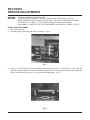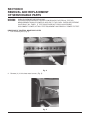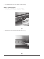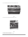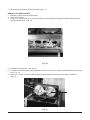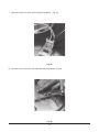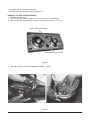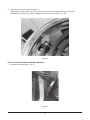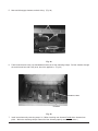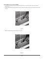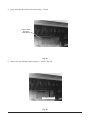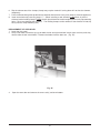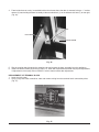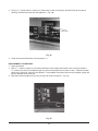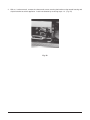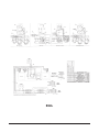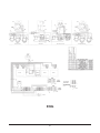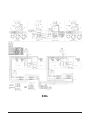
1
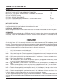
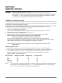
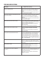
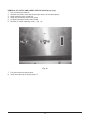
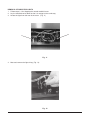
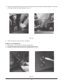
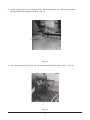
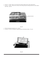
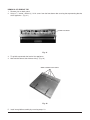
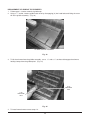
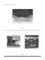
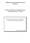
SERVICE MANUAL FOR
ELECTRIC RANGES
MODELS E24L, E36L,
E48L AND E60L SERIES
ML NOS. 52361
THROUGH 52372
MODEL E36L SHOWN
VULCAN-HART COMPANY, P.O. BOX 696, LOUISVILLE, KY 40201- 0696, TEL. (502) 778-2791
FORM 30900
SERVICE MANUAL FOR
ELECTRIC RANGES MODELS
E24L, E36L, E48L AND E60L SERIES
IMPORTANT FOR YOUR SAFETY
THIS MANUAL HAS BEEN PREPARED FOR PERSONNEL QUALIFIED TO SERVICE AND ADJUST
THE EQUIPMENT COVERED BY THIS MANUAL.
INFORMATION ON THE CONSTRUCTION AND INSTALLATION OF VENTILATING HOODS
MAY BE OBTAINED FROM THE "STANDARD FOR THE INSTALLATION OF EQUIPMENT FOR
THE REMOVAL OF SMOKE AND GREASE LADEN VAPORS FROM COMMERCIAL COOKING
EQUIPMENT," NFPA NO. 96 (LATEST EDITION) AVAILABLE FROM THE NATIONAL FIRE
PROTECTION ASSOCIATION, BATTERY MARCH PARK, QUINCY MA. 02269.
FOR AND APPLIANCE EQUIPPED WITH A FLEXIBLE ELECTRIC CORD, A THREE PRONG
GROUNDING PLUG IS SUPPLIED. THIS GROUNDING PLUG IS FOR YOUR PROTECTION
AGAINST SHOCK HAZARD. DO NOT CUT OR REMOVE THE GROUNDING PRONG OF THIS
PLUG. THE GROUNDING PLUG SHOULD BE USED WITH A PROPERLY GROUNDED THREE
PRONG RECEPTACLE. IF THE APPLIANCE IS NOT EQUIPPED WITH A GROUNDING PLUG,
AND ELECTRIC SUPPLY IS NEEDED, GROUND THE APPLIANCE USING THE GROUND LUG
PROVIDED.
FOR YOUR SAFETY
DO NOT STORE OR USE GASOLINE OR OTHER
FLAMMABLE VAPORS/LIQUIDS IN THE VICINITY
OF THIS APPLIANCE.
WARNING
IMPROPER INSTALLATION, ADJUSTMENT,
ALTERATION, MODIFICATION, SERVICE OR
MAINTENANCE CAN CAUSE PROPERTY DAMAGE,
INJURY OR DEATH. READ ALL INSTRUCTIONS
THOROUGHLY BEFORE SERVICING THIS
EQUIPMENT.
2
TABLE OF CONTENTS
DESCRIPTION
PAGE
IMPORTANT CODE, SAFETY AND WARNING INFORMATION
DATA PLATE, ELECTRICAL, AND APPLIANCE CLEARANCE INFORMATION
APPLIANCE FEATURES
SECTION I SERVICE CHECKS
SECTION II SERVICE ADJUSTMENTS
SECTION III REMOVAL AND REPLACEMENT OF SERVICEABLE PARTS
SECTION IV WIRING DIAGRAMS
2
3
3
4-7
8-9
10 - 34
35 - 39
DATA PLATE LOCATION
The appliance data plate stating model number, serial number, manufacturing date and electrical specifications
is located behind the kick panel on the left side appliance front frame.
ELECTRICAL SPECIFICATIONS
Refer to Configuration/Electrical Specification Load Chart label located on the back of the lower kick panel.
CLEARANCES
All models except those equipped with the ESB Broiler require 0" clearance at both sides and rear to combustible
construction. Models with the ESB Broiler require an 8" clearance at the sides and a 2" clearance at the rear
to combustible construction.
FEATURES
26" wide x 22" deep x 121⁄2" high oven with 1250 watt top oven heating elements and 3750 watts bottom heating
elements. Top elements are controlled by infinite switch and the bottom elements are controlled by an adjustable
thermostat. The range top may have cast iron french top plates or optional hot top, griddle or high speed elements
as shown in model no. chart below. The chart below shows only the basic model nos. For additional configuration
refer to the Configuration/Electrical Specification Charts in the back of this manual.
E24L =
24" wide single oven range with (4) french plates or (2) high speed elements or (1) hot top in place
of (2) french plates in the vertical position.
E24FL = 24" wide single oven range with a 24" Griddle top.
E36L =
Single oven range with (6) french top plates or (2) high speed elements or (1) hot top section in place
of (2) french plates in the vertical positions.
E36FL = Single oven range with (2) french top plates and (1) 24" griddle top or (1) hot top section in place of
the (2) french plates.
E36XL = Single oven range with (1) 36" griddle top.
E48L =
48" wide unit with (2) oven sections and (8) french plates or (2) high speed elements or (1) hot top
in place of (2) french plates in the vertical position.
E48FL = 48" wide unit with (2) ovens and a 24" griddle to the right and (4) french plates or (2) Hot tops to the
left.
E60L =
Double oven range with (10) french top plates or (2) high speed elements or (1) hot top section in
place of (2) french plates in the vertical positions.
E60FL = Double oven range with (6) french top plates and (1) 24" griddle top or (3) hot top sections in place
of the french plates.
E60XL = Double oven range with (4) french top plates and (1) 36" griddle top or (2) french top plates, (1) hot
section with (1) 36" griddle top.
In all of the above the french plate sections may be replaced by high-speed elements.
The above may also be equipped with an ESB Elevated Salamander Broiler. These units are indicated by the
Suffix letter B in the unit model number. ESB Broilers cannot be mounted over any unit equipped with hot top
sections.
3
SECTION I
SERVICE CHECKS
WARNING:
WARNING:
UNPLUG OVEN BEFORE SERVICING.
CERTAIN PROCEDURES IN THIS SECTION REQUIRE ELECTRICAL TEST OR
MEASUREMENTS WHILE THE POWER IS APPLIED. EXERCISE EXTREME CAUTION AT
ALL TIMES. IF TEST POINTS ARE NOT EASILY ACCESSIBLE DISCONNECT POWER,
ATTACH TEST EQUIPMENT AND REAPPLY POWER TO TEST.
THERMOSTAT CALIBRATION CHECK
If the product recipe catic for 350 degrees for 30 minutes and at the end of the cooking time with thermostat set
at 350 degrees your product is consistantly under or over cooked the oven thermostat may be out of calibration
and should be checked and adjusted if required.
If calibration is a suspected problem perform steps 1-6 below to determine the center average heating
temperature the oven and refer to Section II of the manual if thermostat calibration is required.
1. Turn oven off, allow it to cool then open the oven door.
2. Place oven rack in center oven position.
3. Place a calibrated potentiometer thermocouple in the oven cavity centered on the oven rack.
4. Turn oven on and set oven temperature to 350 degrees F.
5. Allow the oven to cycle 3 complete times.
6. After the third cycling period, record cycle at highest point, record cycle at lowest point.
Example: High point 360 degrees F. (Burner cycle off temperature)
Low point 340 degrees F. (Burner cycle on temperature)
Differential: If the differential exceeds 25 degrees F. then thermostat should be replaced.
To calculate this example or any other high/low point center oven average follow the method below.
Add the highest and lowest cycle values together then divide this value by 2.
Example: 360 + 340 = 700 then 700 divided by 2 = 350. The calibration set point will be
350 degrees F.
INFINITE SWITCH CHECK
1. With power on using a volt meter check for 120 Volts AC input across H1 and H2 terminals.
2. H2 has 120V AC Output, but it is not a constant output. The output will cycle on and off as long
as the input to the switch is present. The timing of this output is determined by the switch
setting. By timing the switch cycles at various settings you can determine if the switch is
properly working. See the chart below.
DIAL SETTING
PERCENT ON TIME SECONDS ON
SECONDS OFF
Hi
100
ALL
0
Med.
48
15
15
Low
37
8
14
Med. Low
28
7
24
Very Low
7
3
33
NOTE:
The P terminal is a neutral leg of the switch. When the control is turned from the off position to any
other position P is making contact with L1. L1 is a neutral connection. L2 is a 120V AC input.
H1 is used as a neutral point for testing of load control output.
4
ON-OFF SWITCH CHECK
1. Follow steps 1-3 under the 4-Heat switch check except, using an ohmmeter check for continuity in the off
position as follows:
P1 to 2
P2 to 3
P2 to 4
If the above is not proven replace the switch.
5
TROUBLESHOOTING
PROBLEM
CORRECTIVE ACTION
Range is completely dead.
Check to insure the main store power supply is on.
Check to insure the appliance is wired to power
supply.
Check to insure that the appliance power switch is
on and that switch is not bad.
Oven section elements are dead but top surface
elements are working.
Check for proper voltage and connections between
oven section circuit breakers and thermostat.
Check to see if the oven breaker has tripped or is
defective.
Check for proper connections to the terminal block
and main power supply.
Top element of the oven section is dead.
Check voltage of top oven element infinite switch.
Check for voltage at the top oven element terminals.
Check for defective infinite switch.
Check all wiring associated with the element for
good connections.
Check oven thermostat and wire connections.
Bottom element of oven section is dead.
Check oven thermostat and wire connections.
Check for voltage at the bottom oven element
terminals.
Check all wiring associated with the element for
good connections.
French plate or high speed element dead.
Check for voltage between H1 and H2 terminals of
the french plate infinite switch in the HI position.
Check for defective element or wire connections.
Check voltage between the L1 and L2 terminals of
the infinite switch. If you have voltage the switch is
bad. If no voltage, check the supply connections to
the L1 and L2 terminals.
Griddle element dead.
Check for defective griddle thermostat.
Check for voltage at the griddle element terminals.
Check for bad wire connections of the elements and
thermostat.
Hot top section is dead.
Check for defective 4-heat and on-off switches.
Check for element voltage.
Check for bad wire connections of the element, 4heat and on-off switches.
Circuit breaker trips as soon as appliance
is turned on.
Check for short circuit to ground and between lines.
With power off check for resistance between each
line and chassis ground.
With power off check continuity with ohmmeter
between line phases.
6
TROUBLESHOOTING
PROBLEM
The circuit breaker trips after the range
as been operating for a few minutes.
CORRECTIVE ACTION
The slow trip of a circuit breaker is an indication of
overload in a particular circuit. The cause of this
overload could be:
Voltage problem, check element voltage
against store and rating plate voltages.
Element may also be defective;
Measure the amps of the suspicious element and
compare this with the expected value. The value is
calculated by dividing the watt rating of the element
(see wiring diagram) over the supply voltage.
Example: For a 208V french plate the reading would
be: 2000 watt
= 9.6 amps
208 volt
Check for defective breaker:
Measure the amps of the suspicious breaker with all
elements turned fully on. If reading is not exceeding
50 amps and the breaker trips, replace the breaker.
7
SECTION II
SERVICE ADJUSTMENTS
WARNING:
WARNING:
UNPLUG OVEN BEFORE SERVICING.
CERTAIN PROCEDURES IN THIS SECTION REQUIRE ELECTRICAL TEST OR
MEASUREMENTS WHILE POWER IS APPLIED TO THE OVEN. EXERCISE EXTREME
CAUTION AT ALL TIMES. IF TEST POINTS ARE NOT EASILY ACCESSIBLE
DISCONNECT POWER, ATTACH TEST EQUIPMENT AND REAPPLY POWER TO TEST.
OVEN DOOR ADJUSTMENT
1. Lower the kick panel.
2. Pull door spring slightly out with large screwdriver. (Fig. 1)
Fig. 1
3. Using a 5⁄16" socket loosen (2) hex nuts holding the turn buckle in place. Turn the buckle "J" bolts (left and
right side) slightly retighten the nuts and test door for proper closure. Generally the door is properly adjusted
when it closes on its own as you rise it to the half closed position. (Fig. 2)
Fig. 2
8
THERMOSTAT ADJUSTMENT
1. Perform calibration check as stated under Section I.
2. Remove the thermostat knob. (Fig 3)
Fig. 3
3. Insert a flat blade screwdriver into the thermostat dial stem until it reaches the calibration screw.
4. Note the calibrated center oven average as determined under Section 1 Calibration Check. Use that number
as the calibration set point.
5. Turn the adjustment screw to the right to increase the temperature and to the left to decrease the
temperature. A 1⁄4" turn in either direction will change the temperature by 35 degrees.
6. Perform the calibration check again and repeat the above procedure to insure that the correct center oven
average temperature has been obtained.
7. Reinstall the thermostat knob, be sure to align the knob correctly on the thermostat stem.
9
SECTION III
REMOVAL AND REPLACEMENT
OF SERVICEABLE PARTS
WARNING:
WARNING:
UNPLUG OVEN BEFORE SERVICING.
CERTAIN PROCEDURES IN THIS SECTION REQUIRE ELECTRICAL TEST OR
MEASUREMENTS WHILE POWER IS APPLIED TO THE OVEN. EXERCISE EXTREME
CAUTION AT ALL TIMES. IF TEST POINTS ARE NOT EASILY ACCESSIBLE
DISCONNECT POWER, ATTACH TEST EQUIPMENT AND REAPPLY POWER TO TEST.
DROPPING OF CONTROL MANIFOLD COVER
1. Pull crumb tray out. (Fig. 4)
Fig. 4
2. Remove (2) 10-24 sheet metal screws (Fig. 5)
Fig. 5
10
3. Fold control manifold cover down and rest it on the crumb tray.
REMOVAL OF INFINITE SWITCH
1. Follow steps 1- 2 for dropping the control manifold cover.
2. Pull switch knob off of the control manifold cover. (Fig. 6)
Fig. 6
4. Remove the washer nut from the infinite switch stem. (Fig. 7)
Fig. 7
11
5. Lay the manifold cover down so that it rest on the crumb tray. (Fig. 8)
Fig. 8
6. Note and remove the infinite switch wire connections. (Fig. 9)
Fig. 9
7. Remove the switch from the appliance.
8. Reinstall new switch by reversing steps 1 through 6.
12
REMOVAL OF ON-OFF AND 4-HEAT SWITCHS (EGO Hot top only)
1. Pull crumb tray out about 6".
2. Remove the screws at the top left and right corners of the control panel.
3. Lower panel on to the crumb tray.
4. Label and disconnect wires to the switch.
5. Lift panel up and pull off the switch knob.
6. Remove (2) switch mounting screws. (Fig. 10)
Fig. 10
7. Pull switch from the control panel.
8. Install new switch by reversing steps 1-7.
13
REMOVAL OF INDICATOR LIGHTS
1. Follow steps 1-2 for dropping the control manifold cover.
2. Lay the manifold cover down so that it is resting on the crumb tray.
3. Locate the light from the rear of the cover. (Fig. 11)
Fig. 11
4. Note and remove the light wiring. (Fig. 12)
Fig. 12
14
5. Squeeze the light mounting tabs in towards the light body casing and push the light through the manifold
cover opening and out of the appliance. (Fig. 13)
Fig. 13
6. Install new light by reversing steps 1 through 5.
REMOVAL OF THERMOSTAT
1. Follow steps 1-2 for removal of control manifold cover.
2. Pull thermostat knob from the front of the control manifold cover.
3. Remove (2) screws from the front of the manifold cover. (Fig. 14)
Fig. 14
15
4. Note and remove all wiring associated with thermostat. (Fig. 15)
5. Lift up the left top aeration plate assembly to expose the top burner box area. (Fig. 16)
Fig. 15
Fig. 16
6. Open the oven door.
7. Remove the oven rack(s).
8. Lift the thermo bulb out of the bulb clip holders located inside the oven on the top oven back. (Fig.17)
BULB
CLIPS
Fig. 17
16
9. Locate the bulb access hole in the oven cavity, top left hand corner, and carefully feed the bulb
and thermopile lead through the opening. (Fig. 18)
Fig. 18
10. From the burner box top left side, pull the thermopile lead and bulb from the oven. (Fig. 19)
Fig. 19
17
11. Reinstall the new thermostat by reversing steps 1-10.
REMOVAL OF FRENCH PLATE
1. Remove (2) bolts at top of control panel.
2. Lower control panel.
3. Using a 5⁄16" socket remove (1) hex head retaining screw holding the range top mounting bracket to the
front burner box cover. (Fig. 20)
Fig. 20
4. Remove the backsplash. (See fig. 27)
5. Lift up on the aeration plate, push plate towards the rear of the unit, then lift plate assembly out and flip it
over. (Fig. 21)
6. Using a 5⁄16" socket, remove (2) bolts holding the mounting bracket to the french plate assemblies.
(Fig. 21)
Fig. 21
18
7. Note and remove (2) wires from the plate receptacle. (Fig. 22)
Fig. 22
8. Remove the nut and locking bracket from the plate bottom. (Fig.23)
Fig. 23
19
9. Lift plate out of the aeration plate top.
10. Install new french plate by reversing steps 1-9.
REMOVAL OF HIGH SPEED ELEMENTS
1. Remove the back riser.
2. Flip over aeration plate to expose the element terminal ends and wiring.
3. Note and disconnect all element connector and grounding wire(s). (Fig. 24)
WIRE CONNECTION POINTS
WIRE CONNECTION POINTS
Fig. 24
4.
Snap the element out of the ring/bowel assembly. (Fig 25)
Fig. 25
20
5. Install new element by reversing steps 1-4.
When installing new element, be sure to align the element mounting tab with the mounting slot
provided in the element ring before snapping the element firmly in place. (Fig. 26)
Fig. 26
HOT TOP PLATE/ELEMENT ASSEMBLY REMOVAL
1. Remove the backsplasher. (Fig. 27)
Fig. 27
21
2. Using a 5⁄16" socket, remove (2) hex head screws from the upper corners of the control panel.
3. Using a 5⁄16" socket, remove the hex head screws holding the plate mounting bracket to the front burner
box cover. (Fig. 28)
SCREW LOCATION
Fig. 28
4. Flip the hot top plate assembly over. (Fig. 29)
5. Remove (2) 12mm nuts holding the mounting bracket to the plate assembly. (Fig. 29)
Fig. 29
22
6. Note and disconnect the wiring for the hot top section. (Fig. 30)
Fig. 30
7. Reinstall hot plate by reversing steps 1 through 6.
23
REMOVAL OF GRIDDLE TOP
1. Remove riser or back guard.
2. Using a 5⁄16" socket, remove (1) 10-24 screw from the front burner box securing the top mounting bracket
to the appliance. (Fig. 31)
SCREW LOCATION
Fig. 31
3. Tilt griddle up towards the back of the appliance.
4. Note and disconnect the element wiring. (Fig. 32)
WIRE CONNECTION POINTS
Fig. 32
5. Install new griddle assembly by reversing steps 1-3.
24
REPLACEMENT OF GRIDDLE TOP ELEMENTS
1. Follow steps 1-3 under removal of griddle top.
2. Using a 7⁄16" socket, remove griddle base cover by disengaging (9) hex head bolts and lifting the cover
off of the griddle assembly. (Fig. 33)
24" WIDE GRIDDLE ASSEMBLY
Fig. 33
3. To lift the element from the griddle assembly, use a 7⁄16" and a 5⁄16" socket to disengage the element
holding clamps from the griddle plate. (Fig. 34)
5/16"
HEX HEAD
NUT
7/16"
HEX HEAD
NUT
Fig. 34
4. To install new element reverse steps 1-3.
25
REMOVAL OF OVEN BOTTOM
1. Open oven door.
2. Remove oven rack(s).
3. Lift oven bottom tray up and out of the appliance. (Fig. 35)
Fig. 35
REMOVAL OF THE BOTTOM OVEN ELEMENTS
1. Follow steps for removal of the oven bottom.
2. With a 5⁄16" socket, loosen (12) element mounting clamps. (Fig. 36)
LOOSEN CLAMP BOLT
Fig. 36
26
3. Lower the kick panel. (Fig. 37)
Fig. 37
4. With a 5⁄16" socket, remove (2) screws holding the element terminal cover. Flip cover down. (Fig. 38)
Fig. 38
27
5. Note and disengage element terminal wiring. (Fig. 39)
Fig. 39
6. From inside the oven cavity, slip the bottom element out of the mounting clamps. Pull the element through
the oven burner box and cavity area, out of the appliance. (Fig. 40)
ELEMENT CLAMP
ELEMENT
Fig. 40
7. Install new element by reversing steps 1-6. (When installing new element Do Not force element into
place. Work the mounting clamps around until the element properly seats without force.)
28
REPLACEMENT OF TOP OVEN ELEMENT
1. Flip over the left hand top section or aeration plate and let it lay over one of the center top sections.
(See Fig. 21)
2. From the left hand side of the top burner box area, remove the rubber covers on the element terminal ends.
(Fig. 41)
Fig. 41
3.
Note and disconnect the terminal wiring. (Fig. 42)
Fig. 42
29
4. Open oven door and remove the oven rack(s). (Fig.43)
CAVITY AREA
WITHOUT
OVEN RACKS
Fig. 43
5. Loosen (19) top element clamps using a 5⁄16" socket. (Fig. 44)
LOOSEN SCREWS
Fig. 44
30
6. Slip the element out of the clamps (clamps may require removal if turning them will not free the element
completely).
7. Pull the element through the top burner box outwards into the oven cavity and remove it from the appliance.
8. Install new element by reversing steps 1-7. (When installing a new element Do Not force or jam the
element into the holding clamps. Do Not force or jam the terminal ends through the oven cavity top mounting
holes. Force may damage the elements. The holding clamps can be removed if the element will not slip
easily into the clamp mounting slot.)
REPLACEMENT OF OVEN DOOR
1. Lower the kick panel.
2. Using a flat head screwdriver, pry up on both the left and right hand bell cranks (one at a time) until they
release from the bell crank hooks. Remove the hooks from the door arm. (Fig. 45)
Fig. 45
3.
Open the oven door and remove the oven rack(s) and oven bottom.
31
4. From inside the oven cavity, located behind the front frame where the door is mounted, using a 7⁄16" socket,
remove (2) nuts holding the door assembly to the trunnion block (1) on the left door side and (1) on the right.
(Fig. 46)
NUT
DOOR ARM
FRONT FRAME
Fig. 46
5. Slip the trunnion block through the mounting slot and remove the door assembly from the appliance.
6. Install new door assembly by reversing steps 1-5. After door replacement the door may require adjustment.
If adjustment is necessary refer to Section II of this manual under door adjustment.
REPLACEMENT OF TERMINAL BLOCK
1. Lower the kick panel.
2. Using a large flat head screwdriver, note and remove wiring from the terminal block connection points.
(Fig. 47)
Fig. 47
32
3. Using a 5⁄16" socket wrench, remove (3) sheet metal screws securing the terminal block to the control
housing. Remove the block from the appliance. (Fig. 48)
Fig. 48
4. Install new terminal block by reversing steps 1-3.
REPLACEMENT OF BREAKER
1. Lower kick panel.
2. With a 5⁄16" socket, remove (2) hex head retaining screws holding the breaker cover over the breakers.
To remove the cover tilt the bottom right end over the exposed access panel screws. Slide the breaker
panel to the right until it touches the sidewall. Tilt the bottom left end out and over the left door spring and
pull the breaker cover panel out.
3. Note and remove breaker wiring using a large flat head screwdriver. (Fig. 49)
Fig. 49
33
4. With a 5⁄16 socket wrench, remove the sheet metal screws securing the breaker to the control housing and
slip the breaker out of the appliance. Install new breaker by reversing steps 1-3. (Fig. 50)
Fig. 50
34
SECTION IV
WIRING DIAGRAMS
THE NEXT FOUR PAGES ARE
DEDICATED TO WIRING INFORMATION
OF THE E24L, E36L AND E60L
ELECTRIC RANGES
FOR ADDITIONAL WIRING INFORMATION
CONTACT THE VULCAN-HART CO.
SERVICE DEPARTMENT AT THE
PHONE NUMBER LISTED ON THE
BOTTOM FRONT COVER OF THIS MANUAL.
35
E24L
36
E36L
37
E48L
38
E60L
39