1
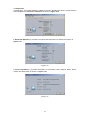
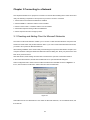
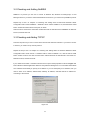
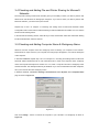
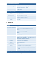
Wireless LAN Card
User Guide
Before operating the unit, please read this manual and retain it for future
Reference
Wireless LAN Card
The user guide is fit for both Wireless LAN Card and Long Range Wireless LAN Card
1
Contents
CHAPTER 1 INTRODUCTION ........................................................................................................................3
1-1 PACKAGE CONTENTS.....................................................................................................................................3
1-2 PC CARD DESCRIPTION .................................................................................................................................3
1-3 SYSTEM REQUIREMENTS...............................................................................................................................3
1-4 FEATURES AND BENEFITS..............................................................................................................................4
1-5 A PPLICATIONS.................................................................................................................................................4
1-6 NETWORK CONFIGURATIONS........................................................................................................................5
CHAPTER 2 INSTALLING DRIVERS & CLIENT UTILITY................................................................8
2-1 INSTALLATION FOR WINDOWS 98SE/ME/2000/XP..................................................................................8
2- 2 CHECKING AFTER INSTALLATION..............................................................................................................11
2- 3 IEEE 802.11 WLAN NIC CLIENT UTILITY.............................................................................................12
2- 4 UNINSTALLING DRIVER AND UTILITY......................................................................................................15
CHAPTER 3 CONNECTING TO A NETWORK..................................................................................... 16
3-1 CHECKING AND A DDING CLIENT FOR M ICROSOFT NETWORKS ............................................................16
3-2 CHECKING AND A DDING NET BEUI ...........................................................................................................17
3-3 CHECKING AND A DDING TCP/IP ...............................................................................................................17
3-4 CHECKING AND A DDING FILE AND PRINTER SHARING FOR M ICROSOFT NETWORKS........................18
3-5 CHECKING AND A DDING COMPUTER NAME & WORKGROUP NAME ....................................................18
CHAPTER 4 TROUBLESHOOTING........................................................................................................... 20
A PPENDIX A
PRODUCT SPECIFICATIONS...................................................................................................22
A PPENDIX B REGULATORY COMPLIANCE INFORMATION .............................................................................29
2
Chapter 1 Introduction
This chapter describes the package contents, PC Card description, system requirements, features &
benefits, applications and network configurations of our wireless LAN products.
1-1 Package Contents
The PC Card package contains the following items
1. One Wireless LAN Cardbus Adapter
2. One Quick Installation Guide
3. One Installation CD
1-2 PC Card Description
The PC Card is a standard PC Card that fits into any PCMCIA Card Type II slot. The PC Card has a LED
indicator and two built-in diversity antennas .
1. Integrated, with built-in diversity Antenna
2. Link LED
802.11 AdHoc mode – Blinking, no matter the wireless is connected or not
Infrastructure – Solid GREEN when the wireless is connected
Off – No wireless activity
1-3 System Requirements
Installation of the PC Card requires:
◆ Laptop PC containing:
– 32-bit CardBus slot (or Desktop PC with PC Card-PCI adapter)
– 32 MB memory or greater
– 300 MHz processor or higher
◆ Microsoft Windows 2000/Windows Millennium Edition/Windows 98
Second Edition/Windows XP/Windows NT 4.0 (with Service Pack 6)
3
1-4 Features and Benefits
2.4/5GHz IEEE802.11a/b/g (draft)
Fully interoperable with IEEE802.11a/b/g
standard and 5GHz IEEE802.11a
(draft) compliant products.
standard compliant
Up to 54Mbps and 108Mps (turbo
Capable of handling heavy data payloads
mode) high-speed data rates
such as MPEG video streaming
Up to 152-bit WEP Data Encryption
Powerful data security
with TKIP
IEEE802.1x Client support (Optional) Enhances authentication and security.
Dynamic Frequency Selection (DFS) Provides flexible selection of the best
support
frequency to allow mobility among all
existing IEEE802.11a/b/g networks
Transmission Power Control (TPC)
Offers flexibility to adjust RF output power
support
Multi-country Roaming (802.11d)
Automatically adjusts regulatory domain to
support
operate in different countries.
1-5 Applications
The wireless LAN products are easy to install and highly efficient. The following list describes some of the
many applications made possible through the power and flexibility of wireless LANs:
1. Difficult-to-wire environments
There are many situations where wires can not or not easily be laid. Historic buildings, older buildings,
open areas and across busy streets make the installation of LANs either impossible or very expensive.
2. Temporary workgroups
Consider situations in parks, athletic arenas, exhibitions, disaster-recovery, temporary office and
construction sites where one wants a temporary WLAN established and removed.
3. The ability to access real-time information
Doctors/nurses, point-of-sale employees, and warehouse workers can access real-time information while
dealing with patients, serving customers and processing information.
4. Frequently changed environments
Show rooms, meeting rooms, retail stores, and manufacturing sites where frequently rearrange the
workplace.
5. Small Office and Home Office (SOHO) networks
SOHO users need a cost-effective, easy and quick installation of a small network.
6. Wireless extensions to Ethernet networks
Network managers in dynamic environments can minimize the overhead caused by moves, extensions to
4
networks, and other changes with wireless LANs.
7. Wired LAN backup
Network managers implement wireless LANs to provide backup for mission-critical applications running
on wired networks.
8. Training/Educational Facilities
Training sites at corporations and students at universities use wireless connectivity to ease access to
information, information exchanges, and learning.
1-6 Network Configurations
To better understand how the wireless LAN products work together to create a wireless network, it might
be helpful to depict a few of the possible wireless LAN PC card network configurations. The wireless LAN
products can be configured as:
1. Ad-hoc (or peer-to-peer) for departmental or SOHO LANs.
2. Infrastructure for enterprise LANs.
3. IP Sharing for 56K/ISDN TA/Cable/DSL Modem – Connect Internet and your SOHO network.
Ad-hoc (peer-to-peer) Mode
This is the simplest network configuration that several computers equipped with the PC Cards that form a
wireless network whenever they are within range of one another (Figure 1-1). In ad-hoc mode, each
client, is peer-to-peer, would only have access to the resources of the other client and requires no the
access point. This is the easiest and least expensive way for the SOHO to set up a wireless network.
Peer to Peer
Wireless LAN PC Card
Wireless LAN PC Card
Wireless LAN PC Card
Wireless LAN USB Adapter
Figure 1-1 A wireless Ad-hoc network
Infrastructure Mode
The infrastructure mode requires the use of an access point (AP). In this mode, all wireless
communications between two computers have to be via the AP no matter the AP is wired to Ethernet
network or stand-alone. If used in stand -alone, the AP can extend the range of independent wireless
LANs by acting a repeater, which effectively doubling the distance between wireless stations as shown in
Figure 1-2.
5
Figure 1-2
Extended-range independent WLAN using AP as repeater
If wired to an Ethernet network as shown in Figure 1-3, the AP serves as a bridge and provides the link
between the server and the wireless clients. The wireless clients can move freely throughout the
coverage area of the AP while remaining connected to the server. Since the ap is connected to the wired
network, each client would have access to server resources as well as to other clients.
Figure 1-3
Single AP bridge
Access points have a finite range, on the order of 50 meters indoor and 100 meters outdoors. In a very
large facility such as an enterprise, a warehouse, or on a college campus, it will probably be necessary to
6
install more than one access point to cover an entire building or campus, as shown in Figure 1-4. In this
scenario, access points hand the client off from one to another in a way that is invisible to the client,
ensuring roken connectivity. Wireless clients can roam seamlessly between different coverage areas and
remain connected to the network.
Figure 1-4
Multiple-AP and roaming
Wireless Router and IP Sharing
In infrastructure mode, in addition to acting as a bridge between an Ethernet and wireless network, the
AP can be configured as a wireless router and IP sharing device for Internet access as shown in Figure
1-5. You don’t have to buy an expensive router. Nor you have to buy several modems and setup phone
lines. Just share one AP, one Modem, single dial-up account, and one phone line, dozens of network
users can go surfing the Internet concurrently.
Figure 1-5
Wireless router and IP Sharing
7
Chapter 2 Installing Drivers & Client Utility
This chapter describes how to install the PC Card drivers and client utility under Windows
95/98/ME/2000/XP.
2-1 Installation for Windows 98SE/ME/2000/XP
This section describes the first-time installation for the driver installation under Windows 98SE/ME/2000.
For a previously installed driver, we provides the InstallShield Wizard, which includes an application for
upgrading the present driver and the Utility.
Installation Procedure:
1. Turn on your computer.
2. Be sure that there is no PCMCIA adapter inserted yet.
3. Insert the Wireless LAN Installation CD into your CD-ROM drive. Then execute Setup.exe by
selecting file from the CD-ROM drive.
4. When the Setup.exe program starting, it will pop up an window as shown in Figure 2-1., click on the
Next button to continue the installation.
Figure 2-1
8
5. After finishing all installation steps, click Finish to complete the installation as Figure 2-2.
Figure 2-2
6. Insert the PC Card into the PCMCIA slot of your computer and wait for the Found New Hardware
Wizard dialog box to display.
7. During the installation, the driver and utility will both been installed into the system, so please select
Install the software automatically (Recommended) as shown in Figure 2-3 and click Next to
search the driver installation file.
Figure 2-3
9
8. Then the system will find the driver and start to install as shown in Figure 2-4.
Figure 2-4
9. The driver currently does not have a digital signature from Microsoft. Therefore, Windows 2000/XP will
show a warning message. Click Yes to proceed with driver installation.
10. Click Finish to complete the driver installation as shown in Figure 2-5 .
Figure 2-5
10
2- 2 Checking after Installation
After installing the driver and utility, follow the steps below to check that the PC Card is
operating correctly.
1. Click the Start button, select Settings, and then click Control Panel.
2. In the Control Panel window, double-click the System icon, then select the Device Manager tab.
3. Double-click Network adapters, then select Wireless Network Adapter as shown in Figure 2-6.
Figure 2-6
4. Right mouse and click the Properties button, then check the message. This device is working
properly is displayed for Device status as shown in Figure 2-7.
Figure 2-7
5. If you find the Yellow (?) sign on the adapter or the above message is not displayed, it
shows the installation is not successful or the wireless LAN PC Card is not operating
properly. Uninstall and re-install the driver, referring to Chapter 2-4 Uninstalling Driver and
Utility.
11
2- 3 IEEE 802.11 WLAN NIC Client Utility
Use the WLAN NIC Client Utility to configure the device driver. Access the Utility by clicking
the Start button and choosing Programs > IEEE 802.11 > ACU. The ACU tray icon is displayed
in the right side of the Toolbar. Launch the ACU by double-clicking the tray icon, or by
right-clicking the tray icon and selecting Launch Client Utility …
WLAN Client Utility is used to display or change the PC Card information about Current
Status, Profile Management and Diagnostics. The client utility will be installed automatically
after installing the driver and utility. After finishing installing the driver and utility, the client utility
will automatically be executed and show a small icon at the right corner of Taskbar whenever
the PC Card is inserted into the PC Card slot of your computer. You can click the taps on the
top of the windows to select various screen messages as shown in Figure 2-8.
Figure 2-8
The tool bar provides three functions of Action, Option and Help.
Action : the Disable Radio function is used to break down the wireless connection, the
Country Select… is used to select suitable country code for the utility and if you
don’t want to see icon shown in Taskbar, you can use Disable Tray Icon function to
hide the icon.
Option : you can use Display settings to change Signal Strength Display Units, Refresh
Interval and Data Disply settings.
Help : click About IEEE 802.11 Client Utility… function to get related information of the Client
Utility.
Except for tool bar’s function, the Utility also provides Current Status, Profile Management and
Diagnostics three main function page for configuration.
Below we explain the use and meanings of the various screen messages.
1. Current Stasus
In Current Status, it will provides user information of Profile Name, Network Type, Wireless Mode,
Current Channel, Link Status, Encryption and IP Address. If you click Advanced button, it will pop
advanced status as shown in Figure 2-9, and in Advanced Status, it provide user information of Country,
Transmit Power Level, Network Name (SSID), Power Save Mode, Frequency, Transmit Rate and
Receive Rate.
12
Figure 2-9
2. Profile Management
In Profile Management, it provides function to New, Modify, Remove or Activate an Profile settings as
shown in Figure 2-10. With default status, the profile will be empty and you have to click New button to
add an profile settings and if there exist Profile file, we can use Modify button to change settings or use
Remove button to erase file or Activate button to activate another profile settings.
Figure 2-10
After click New button, it will pop Profile Management window including General, Security and Advanced
three configuration pages.
In General page : type the desirable profile name into the Profile Name field and the known SSID into
the Network field.
In Security page : the default value is Disable and we provide Pre-Shared Keys, LEAP and Externally
Managed 802.1x Keys for selection.
In Advanced page : you can set Power Save Mode, Network Type, 802.11 Preamble, Transmit Power
Level and Wireless Mode in this page.
In Profile Management, it also provides Available Networks… . for the user to get information
of available AP and Ad Hoc Networks as shown in Figure 2-11.
Figure 2-11
13
3. Diagnostics
In Diagnostics, it provides statistics of Multicast Frames, Broadcast Frames. Unicast Frames
and Total Bytes for Transmit and Receive as shown in Figure 2-12.
Figure 2-12
In Advanced Statistics, it provides more advanced information for reference as shown in
Figure 2-13.
Figure 2-13
In Driver Information, it provides information of Card Name, MAC Address, Driver, Driver
Version and Driver Date as shown in Figure 2-14.
Figure 2-14
14
2- 4 Uninstalling Driver and Utility
If the PC Card installation is unsuccessful for any reason, the best way to solve the problem
may be to completely uninstall the PC Card and its software and repeat the installation
procedure again.
1.Click the Start button, select Settings, and then click Control Panel.
2.In the Control Panel window, double-click the Add or Remove Programs icon, then select the 802.11
Wireless LAN item and remove the driver and utility as shown in Figure 2-15.
Figure 2-15
3.Select Remove in InstallShield Wizard and click Next to start to remove driver then click Finish to
complete driver and utility uninstallation as shown in Figure 2-16.
Figure 2-16
15
Chapter 3 Connecting to a Network
This chapter describes how to prepare for connection to network after installing the PC Card drivers and
utility. The following is required for all computers if you want to connect to a network.
1. Check Client to see if Microsoft Networks is installed.
2. Check if NetBEUI -> Wireless LAN PC Card is installed.
3. Check to see if TCP/IP -> Wireless LAN PC Card is installed.
4. Check file and printer sharing for Microsoft Networks.
5. Check computer name and workgroup name.
3-1 Checking and Adding Client for Microsoft Networks
The Client for Microsoft Networks enables you to connect to other Microsoft Windows computers and
servers and use the files and printers shared on them. If you work in a Microsoft Networks environment,
you need to set up Client for Microsoft Networks .
After finishing installation of the driver & utility and rebooting the com puter as described in Chapter 2, the
computer will show a dialog box titled Enter Network Password dialog box. Enter your password if it had
been set or just click Cancel.
Click Start button, select Settings and then click Control Panel to open the Control Panel window.
In the Control Panel window, double-click the Network icon to open the Network dialog box.
Select Configuration tab to check if Client for Microsoft Networks is installed as shown in Figure 3-1. If
It isn’t, click the Add or Install button. Select Client and click the Add button.
Figure 3-1
Select Microsoft as the “Manufacturer” and “Client for Microsoft Networks ,” as the Network Client, and
then click OK.
16
3-2 Checking and Adding NetBEUI
NetBEUI is a protocol you can use to connect to Windows NT, Windows for Workgroups, or LAN
Manager servers. If you work in a Microsoft Networks environment, you need to set up NetBEUI protocol.
Repeat step 2 and 3 of Chapter 3-1 Checking and Adding Client for Microsoft Networks. Select
Configuration tab to check if NetBEUI -> Wireless LAN PC Card is installed. If not, click the Add or Install
button. Follow same instructions for this part, as above:
Select Protocol and click the Add button. Select Microsoft for Manufacturer and NetBEUI for Network
Protocol, and then click OK.
3-3 Checking and Adding TCP/IP
TCP/IP is the protocol you use to connect to the Internet and wide-area networks. If you want to connect
to Internet, you need to set up TCP/IP protocol.
Repeat the step 2 and 3 of Chapter 3-1 Checking and Adding Client for Microsoft Networks. Select
Configuration tab to check TCP/IP -> Wireless LAN PC Card is installed. If no, click the Add or Install
button. Select Protocol and click the Add button. Select Microsoft for Manufacturer and TCP/IP for
Network Protocol, and then click OK.
If yes, double-click TCP/IP -> Wireless LAN PC Card to open TCP/IP properties as shown in Figure 3-2.
Due to different network applications there are many different settings here. You can select either Obtain
an IP address automatically or Specify an IP address. If you use the Specify an IP address, then you
need to enter an IP address, Subnet Mask, Gateway IP address, and DNS Server IP address for
connecting to the Internet.
Figure 3-2
17
3-4 Checking and Adding File and Printer Sharing for Microsoft
Networks
File and printer sharing for Microsoft networks gives you the ability to share your files or printers with
Windows NT and Windows for Workgroups computers. If you want to share your files or printers with
Microsoft networks, you need to set up this service.
Repeat step 2 and 3 of Chapter 3-1 Checking and Adding Client for Microsoft Networks. Select
Configuration tab to check if File and Printer Sharing for Microsoft Networks is installed. If it isn’t, click the
File and Printer Sharing button.
In the File and Print Sharing window, select what you need, and click OK. Select File and Printer Sharing
for Microsoft Networks, and then click OK.
3-5 Checking and Adding Computer Name & Workgroup Name
Windows uses the computer name and workgroup name to identify your computer on the network.
Please enter an unique name for your computer, the workgroup it will appear in, and a short description
of the computer.
In Windows 98SE/ME, Repeat step 2 and 3 of Chapter 3-1 Checking and Adding Client for Microsoft
Networks. Select Identification tab or User Information tab to check if the computer name, workgroup
name and computer description are entered. If it isn’t, enter a computer name and a workgroup name
and then click OK. The description field may be left blank. If you want to share data with other computers ,
all of you must have the same workgroup name.
In Windows 2000/XP, Click Start > Settings > Control Panel. Select System, select Computer Name
page as shown in Figure 3-3.
Figure 3-3
Then click Change… button to rename the computer or join a Domain or a Workgroup as shown in
Figure 3-4.
18
Figure 3-4
19
Chapter 4 Troubleshooting
This chapter describes the problems that may occur when installing a PC Card and their corresponding
solutions.
Symptom
Solution
Verify that the PC Card is properly
inserted into the PC Card slot.
Windows does not
detect the PC Card when
installed.
Driver fails to load
Check whether the computer has a
Plug and Play BIOS.
Windows 95/98/ME/2000/XP might not
detect the PC Card if a previous
installation of the PC Card was
cancelled before it was finished.
Remove the previous driver, and perform
the installation again.
A resource conflict could exist.
For Windows 95/98/ME/2000, use the
Device Manager to resolve resource
conflicts.
Select System from the Control Panel,
then click on the Device Manager tab.
A device conflict under Windows
95/98/ME/2000 may be related to
the PC Card.
For Windows 95/98/ME/2000, use the
Computer properties to identify the
used I/O port addresses and IRQ
values.
Device conflict on a
Windows system
If there is a device conflict, select
alternative settings for I/O Base Address
or IRQ values. If you know which device
is conflicting with the PC Card, you have
the option of changing that device’s I/O
address or IRQ instead of changing the PC
Card.
20
No resource conflicts were
detected, but the wireless
station does not attach to
the network
Nonfunctioning card LED
Verify that the SSID of the PC Card
matches that of the access point. Use
the Network Configuration Properties
Application in the Control Panel to
modify the SSID.
Verify that the Network Mode of the
PC Card is configured correctly.
The PC Card is not powered on. The
cause may be:
Ÿ No Driver loaded or installed.
Ÿ Card – Driver mismatch which
prevented the driver from loading.
Ÿ Device conflict which prevented the
driver from loading.
Actions:
Ÿ Verify that a driver has been installed.
Ÿ Determine if there is a conflict with
Weak signal or
intermittent connection.
another device.
Try reorienting the antenna. The PC
Card antenna is attached to the end
of the PC Card. For best use of the
antenna:
Keep the area around the antenna
clear from materials that could block
radio transmission, such as metal
objects, electronic devices, and
cordless telephones.
If your signal is weak, change the
direction of the antenna slightly.
If necessary, move your notebook
computer a few inches to find a better
signal.
Use the Link Quality and Signal Strength
display in the Client Utility to determine
the best location and orientation for a
network connection.
21
Appendix A Product Specifications
1.
IEEE802.11a
General
Media Access Control
CSMA/ CA
Compatibility
IEEE802.11a & Wi-Fi5 Compliant
Regulations
FCC Part 15/UL, ETSI 300/328/CE
Operating Voltage
3.3V/5V
Radio, Frequency and Output Power
Data Transfer Rate
Frequency Band
6,9,12,18,24,36,48,54Mbps 72,96,108Mbps in Turbo mode
5.150 - 5.350 GHz
5.250 - 5.350 GHz
5.725 - 5.825 GHz
Modulation
Channels
OFDM (64-QAM, 16-QAM, QPSK , BPSK)
FCC : 12 non-overlapping channels
CE :19 non-overlapping channels
TELEC : 4 non-overlapping channels
Output Power
Sensitivity
Up to 18dBm
-81dBm @ 6Mbps
-79dBm @ 18Mbps
-71dBm @ 48Mbps
-80dBm @ 9Mbps
-78dBm @ 24Mbps
-68dBm @ 54Mbps
-79dBm @ 12Mbps
-76dBm @ 36Mbps
Network Information
Network Architecture
Support Ad-hoc networks and Infrastructure communications to
wired Ethernet networks via Access Point
Drivers
Windows 98/ME/2000/XP
Security
IEEE802.1x with EAP-TLS, EAP-TTLS and EAP-MD5,
22
WEP (64, 128, 152bit) and AES Support
Environmental Specifications
Temperature Range
-10°C to 60°C (14°F to 140°F) - Operating
-40°Cto 70°C (-40°F to 158°F) - Storage
Humidity (non-condensing)
5%~ 95% Typical
Physical Specifications
Interface
Dimensions (H*W*L)
32-bit CardBus PC Card Standard V7.1 Type II
118(L) mm x 54(W) mm x 7.5(H) mm
( 4.65(L) in x 2.13(W) in x 0.30(H) in )
Weight
2.
45 g ( 0.1 lb )
IEEE802.11g
General
Data Rates
802.11g : 6, 9, 12, 18, 24, 36, 48 & 54Mbps.
802.11b : 1, 2, 5.5, 11Mbps.
Network Standards
Compliance
Drivers
Operational voltage
Security
IEEE 802.11g draft, IEEE 802.11b, IEEE 802.11
FCC Part 15/UL, ETSI 300/328/CE
Windows 98/ME/2000/XP
3.3/5 V
IEEE802.1x Support for LEAP (Optional)
WPA - Wi-Fi Protected Access (64,128,152-WEP with TKIP,
Shared Key Authentication)
AES (Advance Encryption Security) Support
RF Information
Frequency Band
2.412~ 2.462GHz(US)
2.412~ 2.484GHz(Japan)
2.412~ 2.472GHz(Europe ETSI)
2.457~ 2.462GHz(Spain)
23
2.457~ 2.472GHz(France)
Channels
11 for North America, 14 for Japan, 13 for Europe,
2 for Spain, 4 for France
Media Access Protocol
Carrier sense multiple access with collision avoidance
(CSMA/CA)
Modulation Technology
802.11g : OFDM (64-QAM, 16-QAM, QPSK, BPSK)
802.11b : DSSS (DBPSK, DQPSK, CCK )
Receive Sensitivity (Typical)
-91dBm @ 1Mbps
-83dBm @ 12Mbps
-89dBm @ 2Mbps
-82dBm @ 18Mbps
-89dBm @ 5.5Mbps -79dBm @ 24Mbps
-84dBm @ 6Mbps
-77dBm @ 36Mbps
-84dBm @ 9Mbps
-74dBm @ 48Mbps
-87dBm @ 11Mbps
-71dBm @ 54Mbps
Transmit Output Power
802.11g: Up to 18dBm
802.11b: Up to 21dBm
(Typical)
Physical
LED
RF Link activity
Interface
32-bit CardBus PC Card Standard V7.1 Type II
Antenna
Integrated built-in diversity Antenna
Dimensions (HxWxL)
6.3mm x 54mm x 118mm ( 0.30in x 2.13in x 4.65in)
Environmental
Temperature Range
-10°C to 60°C (14°F to 140°F) - Operating
-40°Cto 70°C (-40°F to 158°F) - Storage
Humidity
5%~95% Typical
(non-condensing)
24
3.
IEEE802.11a/b
General
Media Access Control
Compatibility
CSMA/ CA
WECA (Wi-Fi & Wi-Fi5) Compliant
IEEE802.11a & IEEE802.11b Compliant
Regulations
Operating Voltage
FCC Part 15/UL, ETSI 300/328/CE
3.3V/5V
Radio, Frequency and Output Power
Data Transfer Rate
Frequency Band
6,9,12,18,24,36,48,54Mbps
1,2,5.5&11Mbps
72,96,108Mbps for Turbo mode
Auto-Fallback
5.150 - 5.350 GHz, 5.250 - 5.350 GHz
2.412 - 2.484GHz
5.725 - 5.825 GHz
Modulation
Channels
OFDM
DSSS
(64-QAM, 16-QAM, QPSK, BPSK)
(CCK, BPSK, QPSK)
U.S: 12 non-overlapping channels
3 non-overlapping
Europe:19 non-overlapping channels
channels
Japan: 4 non-overlapping channels
Output Power
Up to 18dBm
Up to 21dBm
Network Information
Network Architecture
Support
Ad-hoc
networks(without via Access Point) and
Infrastructure communications to wired Ethernet networks via
Access Point
Drivers
Windows 98SE/ME/2000/XP
Security
IEEE802.1x with EAP-TLS, EAP-TTLS and EAP-MD5,
WEP (64, 128, 152bit) and AES Support
25
Environmental Specifications
Temperature Range
-10°C to 60°C (14°F to 140°F) - Operating
-40°Cto 70°C (-40°F to 158°F) - Storage
Humidity (non-condensing)
5%~ 95% Typical
Physical Specifications
Interface
Dimensions (H*W*L)
32-bit Cardbus PC Card
118(L) mm x 54(W) mm x 7.5(H) mm
( 4.65(L) in x 2.13(W) in x 0.30(H) in )
Weight
4.
40 g ( 0.09lb )
IEEE802.11a/g
General
Data Rate (Auto-rate capable)
802.11a :
6, 9, 12, 18, 24, 36, 48, 54 & 108Mbps turbo mode.
802.11g :
6, 9, 12, 18, 24, 36, 48 & 54Mbps.
802.11b :
1, 2, 5.5, 11Mbps.
Network Standards
WECA
(Wi-Fi
&
Wi-Fi5),
IEEE802.11,
IEEE802.11a,
IEEE802.11g draft, IEEE802.11b, draft IEEE 802.11e, f, h,
and i standards, IEEE802.11x(Optional)
Compliance
Drivers
Operational voltage
Security
FCC Part 15/UL, ETSI 300/328/CE
Windows 98/ME/2000/XP
3.3/5 V
Ÿ
IEEE802.1x Support for LEAP (Optional)
Ÿ
WPA - Wi-Fi Protected Access (64,128,152-WEP with
TKIP)
Ÿ
AES (Advance Encryption Security) Support
RF Information
26
Frequency Band
802.11a
Ÿ
5.15~5.25GHz
Ÿ
5.25~5.35GHz
Ÿ
5.725~5.825GHz
802.11b/g
Ÿ
2.412~ 2.462GHz(US)
Ÿ
2.412~ 2.484GHz(Japan)
Ÿ
2.412~ 2.472GHz(Europe ETSI)
Ÿ
2.457~ 2.462GHz(Spain)
Ÿ
2.457~ 2.472GHz(France)
Media Access Protocol
CSMA/CA with ACK
Modulation Technology
802.11a/g : OFDM (64-QAM, 16-QAM, QPSK, BPSK)
802.11b : DSSS (DBPSK, DQPSK, CCK )
Receive Sensitivity (Typical)
802.11a :
-81dBm @6Mbps -79dBm @ 18Mbps -71dBm @ 48Mbps
-80dBm @9Mbps -78dBm @ 24Mbps
-68dBm @ 54Mbps
-79dBm @ 12Mbps -76dBm @ 36Mbps
802.11b/g :
-91dBm @ 1Mbps
-87dBm @ 11Mbps -74dBm @ 48Mbps
-89dBm @ 2Mbps -83dBm @ 12Mbps -71dBm @ 54Mbps
-89dBm @ 5.5Mbps -82dBm @ 18Mbps
Transmit Output Power
-84dBm @ 6Mbps
-79dBm @ 24Mbps
-84dBm @ 9Mbps
-77dBm @ 36Mbps
802.11a/g : Up to 18dBm
802.11b : Up to 21dBm
Physical
LED
RF Link activity
Interface
32-bit CardBus PC Card Standard V7.1 Type II
Antenna
Integrated built-in diversity Antenna
Dimensions (HxWxL)
6.3mm x 54mm x 118mm ( 0.30in x 2.13in x 4.65in)
Environmental
Temperature Range
-10°C to 60°C (14°F to 140°F) - Operating
27
-40°Cto 70°C (-40°F to 158°F) - Storage
Humidity (non-condensing)
5%~95% Typical
All specifications are subject to change without notice.
28
Appendix B Regulatory Compliance Information
Radio Frequency Interference Requirements
This device complies with Part 15 of FCC Rules and Canada RSS-210.
Operation is subject to the following conditions:
1. This device may not cause harmful interference.
2. This device must accept any interference received, including interference that may cause undesired
operation.
3. To comply with RF safety requirements, you must maintain a distance of 20 cm from the antenna when
operating the device.
4. This transmitter must not be co-located or operating in conjunction with any other antenna or
transmitter.
5. Since the module is installed inside the end product, a label showing that the product contains a RF
module should be affixed on the end product in a visible area. This label should also show the FCC
ID.
Interference Statement
This equipment has been tested and found to comply with the limits for a Class B digital device, pursuant
to Part 15 of the FCC Rules; these limits are designed to provide reasonable protection against harmful
interference in a residential installation. This equipment generates, uses, and can radiate radio frequency
energy. Thus, if it is not installed and used in accordance with the instructions, it may cause harmful
interference to radio communications. However, there is no guarantee that interference will not occur in a
particular installation. If this equipment does cause harmful interference to radio or television
reception,( which can be determined by turning the equipment off and on), the user is encouraged to try
to correct the interference by one of the following measures:
◆ Reorient or relocate the receiving antenna.
◆ Increase the separation between the equipment and receiver.
◆ Connect the equipment to an outlet on a circuit different from that to which the receiver is connected.
◆ Consult the dealer or an experienced radio/TV technician for help.
FCC Caution: To assure continued compliance, (example – use only shielded interface cables when
connecting to computer or peripheral devices). Any changes or modifications not expressly approved by
the party responsible for compliance could void the user’s authority to operate this equipment.
29