1
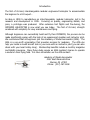
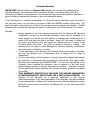
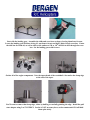
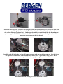
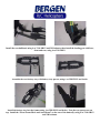
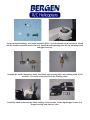
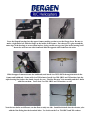
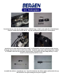
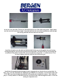
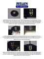
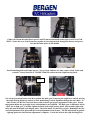
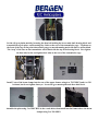
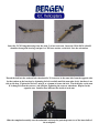
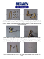
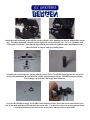
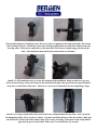
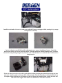
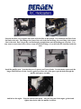
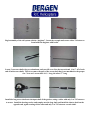
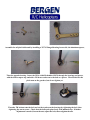
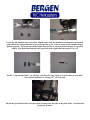
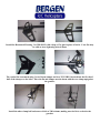
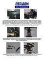
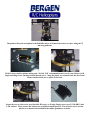
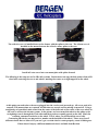
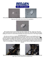
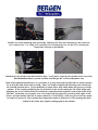
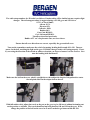
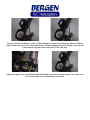
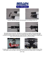
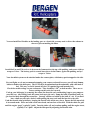
WARNING!
The radio controlled model helicopter built from this kit is not a toy and is not meant for
children. It is a flying machine capable of causing property damage and serious bodily
harm to both the operator/assembler and/or spectator if not built and operated correctly
and responsibly. Rotating components, especially the main rotor blades, are an everpresent danger.
Model helicopters operate differently than model cars and airplanes. Helicopters by their
nature are not positively stable, meaning that even if properly assembled and adjusted,
helicopters will not recover from an unwanted flight attitude, nor will they hold any
particular orientation without constant control inputs from the pilot.
IT IS YOUR EXCLUSIVE RESPONSIBILITY TO PROPERLY BUILD, MAINTAIN
AND OPERATE THIS HELICOPTER. Bergen R/C Helicopters has spent
considerable time making this product reliable and easy to build, but only
the operator can insure that it is safe. Because the safe operation of this
helicopter is beyond the control of the Manufacturer and distributor, the
owner/operator assumes all risk of use.
Construction Manual
Acknowledgments
Bergen R/C Helicopters wishes to thank our friends and customers for their
continuing support during the development of the Intrepid Helicopter.
The Instruction Manual and illustrations were completed with the input of
numerous customers and staff. We wish to recognize Gary Wright, who had
been the test pilot and helicopter guru in its early years. We would also like
to recognize Mike DeMetz for his continuous support and knowledge in
electronics and maintenance.
Staff
Chris Bergen; Chief Executive Officer
Larry Bergen; Chief Design Engineer and General Manager
Maryann Pratt; Office Management
Mike Bergen; Programmer, Engineer
Larry Mihills; Machinist
Malorie Zastrow; Test Pilot/Engineer
Bergen R/C Helicopters LLC
1101 Follett Drive
Cassopolis, MI 49031
Voice: (269) 445-2060
Fax: (269) 445-2250
Web: www.bergenrc.com
Email: [email protected]
Introduction
The first of its kind, interchangeable modular engineered helicopter to accommodate
the beginner to a FAI expert…
An idea in 1994 to manufacture an interchangeable, modular helicopter, led to the
research and development in 1995. Focusing on quality, engineering details, and
price, a prototype was produced. After extensive test flights and fine-tuning, the
INTREPID HELICOPTER is now what you see today. The first of its kind, strength
combined with simplicity for easy maintenance and flying.
Although beginners can successfully build and fly their INTREPID, the process can be
made significantly easier with the help of an experienced modeler and instructor pilot.
We recommend that all beginners join the Academy of Model Aeronautics (AMA). The
AMA is a non-profit organization that provides services for modelers. The AMA can
help you locate a model aircraft club in your area with an instructor pilot (you can also
check with your local hobby shop). Membership benefits include a monthly magazine
and liability insurance. Many flying clubs require an AMA modeler’s license to operate
a model on their flying field. For more information on the AMA contact:
Academy of Model Aeronautics
5151 East Memorial Drive
Muncie, IN 47302
Phone: (317) 287-1256
Consumer Warranty
IMPORTANT! Before building the Observer EB Helicopter kit, read and fully understand the
following warranty, and review the entire Construction Manual. By building and/or flying this
helicopter you indicate your acceptance of the following warranty terms and conditions, and further
agree to build and operate this helicopter in safe and responsible manner.
If you find any term or condition unacceptable, or if you feel that this helicopter is just not suited to
you, you may return it to your place of purchase in NEW and UNUSED condition within thirty (30)
days of the date of purchase for a refund of the purchase price less shipping and handling. Partially
assembled kits, and kits with opened parts packs or missing parts can not be returned for a refund.
Warranty:
1. Bergen warrants to the first consumer Purchaser that the Observer EB helicopter
substantially conforms to its published description when used as intended as a
hobby product, and will be free from defects in materials and workmanship for a
period of 90 days after the date of purchase. Bergen R/C will repair or replace (at
his option) any defective part, and supply any missing part at no charge to the
Purchaser within this period. We make no warranty, express or implied. This
warranty does not apply to parts damaged by improper assembly, modification,
abnormal service or handling, or crashes.
2. To take advantage of this warranty, the Purchaser must provide proof of purchase,
and ship any defective part (at Purchaser’s cost) to Bergen R/C for repair or
replacement.
3. It is the responsibility of the Purchaser to properly assemble, maintain and operate
this helicopter in accordance with manufacture’s instructions, AMA safety codes,
local laws and ordinances, and COMMON SENSE. It is also the responsibility of the
Purchaser, when operating this helicopter, never to operate it in any way, which
might endanger persons or property including the Purchaser. Purchaser is advised
to carry appropriate liability insurance such as that commonly provided to modelers
by the AMA.
4. THIS WARRANTY SPECIFICALLY EXCLUDES THE IMPLIED WARRANTIES
OF MERCHANTABILITY AND FITNESS FOR A PARTICULAR PURPOSE. The
selection of this helicopter for a particular application or use (beyond
hobby/entertainment) is the sole responsibility of the Purchaser. Any advice supplied
by any representative of Bergen R/C pertaining to any particular application is given
freely as an opinion and is not meant to bind Bergen R/C or in any other way modify
this warranty.
1. Not withstanding the paragraph above, this warranty is in addition to whatever
implied warranties may be granted to the Purchaser by law. To the extent
permitted by law, all implied warranties, including the warranties of merchantability
and fitness for a particular purpose are limited to a period of (1) year from the date
of purchase. Some states do not allow limitations on how long an implied warranty
last, so the above limitation may not apply.
2. This warranty shall be the sole and exclusive remedy available to the Purchaser.
Correction of defects, in the manner and for the period of time specified above, shall
constitute complete fulfillment of all liabilities and responsibilities of Bergen R/C to
the Purchaser, and shall constitute full satisfaction of all claims, whether based on
contract, negligence, strict liability or otherwise. Bergen R/C shall not be liable for
any cost or expenses incurred in; the replacement of any effective or nonconforming parts, and IN NO EVENT SHALL BERGEN R/C BE LIABLE FOR
INCIDENTAL OR CONSEQUENTIAL DAMAGES, OR ANY DAMAGES DUE TO
THE USE OR INABILITY TO USE THIS PRODUCT. Bergen R/C shall not be
liable, or in any way responsible, for any damages related to modifications, repairs,
attempted repairs, or crashes.
IN NO EVENT SHALL BERGEN R/C’s
OBLIGATIONS TO THE PURCHASER EXCEED THE ORIGINAL PURCHASE
PRICE PAID BY THE PURCHASER.
3. Some states do not allow exclusion of incidental or consequential damages, so the
above exclusion may not apply. This warranty gives the Purchaser specific legal
rights. The Purchaser may also have other rights, which vary, from state to state.
4. No modification or amendment to this warranty will be effective unless reduced to
writing and signed by an authorized representative of Bergen R/C Management.
If you do not understand any aspect of this warranty, you may contact
Bergen R/C Helicopters for clarification. IF YOU DO NOT AGREE WITH ANY ASPECT OF THIS
WARRANTY, RETURN THE UNASSEMBLED HELICOPTER TO YOUR MANUFACTURER FOR A
REFUND.
Bergen R/C Helicopters believes that information contained within its published materials is accurate
as of the date of publication, and is not responsible for inadvertent errors or omissions. Bergen R/C
reserves the right to make changes and improvements in its products without notice.
Chris and Larry Bergen
Bergen R/C Helicopters
Congratulations on your purchase of a Bergen R/C Helicopters Observer EB.
The EB stands for Extended Boom, allowing the use of 810 mm rotor blades.
There are a few things we recommend in the assembly and use of your Observer EB, and we’ll spell those
out as we go, but for now, our first recommendation is a good quality set of hardened allen drivers. We
have found that standard allen wrenches are too soft, and you run the risk of rounding off the inside hex
of the SHCS that we use in the assembly of the helicopter.
You will also need Blue Loctite throughout the assembly, and some good quality grease that is compatible
with rubber, which will be used to lube the O’rings in the rotor head.
Oil and fuel mix is a hot topic on the internet, and you will use what you want, but here, at least, is our
recommendation based on our experience of many years of using gas engines in helicopters. We
recommend using 100% synthetic oil such as Blue Marble, available from B.H. Hanson, Yamalube, or
even Pennzoil outboard marine engine oil. The clue here is 100% synthetic, not a blend, not ashless, and
certainly not a concentrated oil such as Amsoil, that requires using less oil.
Mix your oil, 6 oz to a gallon, of 87 octane gasoline, not camper fuel or some other substitute. Higher
Octane fuel will NOT add performance, just cost, and may cause predetonation. This mix to be used for
the first 2 gallons of use, then reduce the oil to 5 oz per gallon.
Our reasoning for this mix is simple. We feel that more oil is a safety measure for your engine. It’s
protection against a lean run that may be accidental due to an air leak or by not being used to tuning a
gas engine. Many engines have had to be replaced due to the fact of burning them up because of a lean
run, using less than the recommended amount of oil. As I said earlier, you will run what you want, but if
you want the performance out of your helicopter that you purchased it for, use our recommendations and
it will work just fine.
Start with the landing gear. Assemble the skids and cross bars as shown, leaving them loose for now.
Locate the landing gear skid bars in bag #1, use them to locate and drill 2 holes in each cross bar. Center
the skid bar fore and aft, as well as side to side, and use a #30 or 1/8th drill bit to drill through the cross
bar. Set the landing gear aside for now.
Gather all of the engine components. Note the tapered end of the crankshaft. Also notice the sharp edge
at the end of the taper.
You’ll want to remove that sharp edge, either by buffing or carefully grinding the edge. Install the pull
start adapter using 3 ea 5X12 FHCS. Loctite is NOT necessary here, as the countersunk G10 will hold
them quite nicely.
Install the pull start using 4 ea 4X12 SHCS. Again, loctite isn’t needed, however if you feel the need, you
can use a drop of CA glue in place of loctite. Note the orientation of the pull start handle, on the same
side as the carburetor insulator block. On the opposite end of the engine, install the fan shroud mount
plate, using 4 ea 5X12 SHCS and loctite this time. Also note the orientation of the plate; this will be
important when you mount the fan shroud.
Installing and dial indicating the fan will be more accurate with the spark plug removed. Seat the fan on
the tapered end of the crank, and install the 6X25 SHCS and ¼” split washer, using loctite. Do not
torque the bolt down yet, just snug it.
Dial indicate the fan, looking for runout indication as shown.
Tap the high side down carefully, using a small hammer, hitting flat on the tops of the fan blades, then
checking the runout. It usually takes only a sharp tap to bring it in. Now torque down on the bolt
holding the fan to the engine. Check the runout again. If it has runout, give it another tap on the high
side and recheck. You should be able to get the runout to less than .002 without a lot of difficulty. If you
are having difficulty, remove the fan. Check the runout of the crankshaft itself. It should also be less
than .002. Look into the fan hub to ensure there is no burr in the tapered end, preventing it from seating
properly.
This is what it should look like when you’re done. One side reads 0.00, as does the opposite side. This
took all of 10 minutes, including taking the pics!!
Set the fan shroud over the fan and head of the engine. Carefully, using a hair dryer, warm the shroud to
fit it to the mount, installing the 3X16 SHCS as you go.
When you get all 4 SHCS installed, warm the entire shroud to relieve any stress that could cause cracks
in the future. Install 4 ea 3M locknuts on the SHCS. DO NOT over torque these nuts; you will crack the
ears on the first run of the engine. Snug is good enough.
Gather the lower frame components from bag #1. Start with the “butterfly” and the 2 “Front Frame
Plate Bars”, noting the orientation.
Using 6 ea 3X16 SHCS and 3M locknuts, mount the bars on the butterfly, then slide the one leg into the
lower frame, again using 3X16 SHCS and 3M locknuts through the “front frame plate bar” to secure in
place. Repeat for other lower frame half. Note that the lower frames are “handed”, left and right. You
can tell the difference by the countersunk holes on the lower edge of the frame. The countersink faces
“out”.
Install the rear bulkhead using 4 ea 3X16 SHCS and 3M locknuts, then install the landing gear skid bars,
front and rear, using 4 ea 3X8 FHCS.
Assemble the rear battery tray with battery tray spacers, using 6 ea 3X8 FHCS and loctite.
Install the battery tray into the frames using 4 ea 3X8 SHCS and loctite. Note the tray spacers are on
top. Install the “Front Frame Block and Arm Mount” on the rear of the butterfly, using 4 ea 3X16 SHCS
and 3M locknuts.
Install the lower frame assembly onto the landing gear, using 4 ea 3X16 SHCS and 3M locknuts. Center
and rotate the skid tubes to your liking, then drill a #50 pilot hole in the boss, into the aluminum skid
tube, on the underside of the gear and install the 2 ea 3X8 self tapping screws. I typically install these
into the rear cross bar, leaving the front crossbar able to flex.
Install the engine into the lower frames, spark plug facing to the rear (remove the plug for ease of
installation). Note the vertical slots in the lower frames and the horizontal slots in the pull start adapter.
In these slots, install 4 ea 3X18 SHCS with the thick special washers provided, one washer on the outside,
one on the inside.
Turn the framework over to access the underside, and install the washers and 3M locknuts. Do not
tighten at this time, as you will need to set the gear mesh later on. Note that you can move the engine up
and down, as well as forward and aft.
Locate the delrin bushings, steel inserts and 4X16 SHCS. Note the chamfer on the steel insert. Install
with the chamfer toward the head of the bolt. Install the delrin bushings onto the fan hub using loctite,
and tighten securely.
Assemble the clutch components, clutch, clutch bell, triple bearing block, and retaining collar w/3X3
setscrews. Use loctite on the setscrews in the retaining collar.
Install the clutch system onto the delrin bushings on the fan hub. Gather up the upper frames, 4 ea
flanged bearings, and collective axles.
Press the flanged bearings into the upper frames, making certain to seat the flange down. Be sure to
make a right and a left, with the flange on the inside of the frames. Put a drop of CA glue around the
outer edge of the bearings to secure them in place, being careful not to get any glue in the bearing itself.
Insert the axles into one side frame and slide the opposite side frame onto the axles.
Slide the upper framework onto the bulkheads, and install 4 ea 3X35 SHCS through the holes in the
frames and bulkheads. Secure with 4 ea 3M locknuts. Install 4 ea 3X8 SHCS and 3M washers into the
triple bearing block above the clutch, loosely for now. Find the Elevator Yoke assembly and the 2 shafts
with flats on them. You’ll need 2 ea 3X4 SHCS and 3M washers as well.
Note the two shafts are different; one has flats on only one side. Install both shafts into the elevator yoke
with the flats fitting into the broached holes. Use loctite on the 2 ea 3X4 SHCS and 3M washers.
Insert the elevator yoke into the upper frames, with the longer of shaft on the right side of the helicopter.
Find the 2 main shaft bearing blocks. Note the cutout portion on the lower bearing block.
Install the lower main shaft bearing block, using 2 ea 3X35 SHCS, note the orientation of the bearing,
facing up. The elevator yoke is removed for clarity. Install the upper main shaft bearing block, using 4
ea 3X8 SHCS also note the orientation of the bearing, facing down this time, hump side up. Loosely
install 2 ea 3M locknuts on the lower bolts.
Assemble the tail drive transmission next. Insert the shaft into the delrin coupler until the holes line up
and install the cross pin securing the two pieces together.
Secure the cross pin with a 3X4 setscrew threaded into the rear of the shaft, using loctite. Make doubly
sure the setscrew secures the crosspin. Insert the shaft into the rear of the transmission cradle through
the bearing, and slide the brass tube onto the shaft.
Install the tail pinion onto the shaft and slide the shaft all the way in, through the forward bearing.
Looking through the setscrew hole, locate the divot in the shaft. If it doesn’t line up, look through the
second hole in the pinion. Install a 3X4 setscrew in this hole, using loctite. A second setscrew is not
necessary and may interfere with the bolts in the main gear.
Install the tail transmission into the upper frames, engaging the ears into the lower bearing block. In
these “ears”, note the slotted hole for adjustment up and down to set the mesh. You’ll need to remove the
3X35 SHCS previously installed, the reinstall it after getting the transmission in place. Don’t tighten it
just yet. Loosely install 4 ea 3X8 SHCS into the rear 4 holes of the cradle through the frames. Locate the
main gear components next.
Install the autorotation hub into the main gear with the longer portion of the hub facing up. Use 4 ea
3X8 Low Head Cap Screws and loctite to secure. Insert the main shaft down through the upper bearing
block, install the 3 pieces of the thrust bearing and 1 split collar on the shaft with the “ring” facing up
toward the bearing, slide the shaft down a little farther and install the second split collar, below the
elevator yoke, with the “ring” facing down toward the bottom bearing.
Continue pushing the main shaft down, through the bottom bearing, insert the main gear below the
bottom bearing block and slide the main shaft through the auto hub. Place the bottom collar on the main
shaft and install the 4-40 bolt through the collar and mainshaft, with loctite. This is one of the 2
standard, not metric, bolts on this helicopter.
Pull up on the mainshaft, push down and tighten the lower split collar. This is where the hardened allen
drivers are a must. You’ll notice the heads of the bolt are turned down to fit the collar, making them
very easy to strip the heads. Slide the upper collar and thrust bearing up to the upper bearing and secure
the bolt. DO NOT use loctite on these bolts.
Gather the 26 mm threaded frame spacers and 29 mm non-threaded frames spacers with 4 ea 3X40
SHCS. Secure the rear of the frame sets together by inserting the bolt through the frames and spacer,
into the threaded spacer in the middle.
Install remaining bolts and frame spacers. Now go back, and one at a time, remove a bolt, loctite and
reinstall. Loosely install 4 ea 3X8 SHCS and 3M washers into the triple bearing block.
Parallel to
each other
Now set the gear mesh between the drive pinion and main gear by moving the engine fore and aft, moving
the triple bearing block fore and aft as well, maintaining vertical alignment through the start shaft. In
other words, you DO NOT want the drive train cocked to get proper engagement of the gears. Proper
engagement means the gears spin freely with minimal or no backlash. The main gear is machined, and as
such, has no high spot. Carefully tighten the bolts in the triple bearing block, and carefully tighten the
bolts and nuts in the pull start adapter plate. Check the mesh, if it moved, try again. Remember the fore
and aft adjustment in the plate and the vertical adjustment in the frames. The fan hub should be pushed
right up against the clutch when adjustment is complete. Loctite the bolts in the triple bearing block.
Set the tail gear pinion mesh by loosening the thru bolt holding the lower main shaft bearing block and
transmission cage in place, and loosening the 4 bolts at the rear of the transmission cage. Tap down on
the front of the cage at the point shown until you get a smooth running mesh with little or no backlash.
The “step” of the ears on the transmission will sit flush with the top of the bearing block. Now tighten
the thru bolt, loctite and tighten the 4 bolts in the rear of the transmission cage.
Install 3 sets of the boom clamps into the rear of the upper frames, using 6 ea 3X35 SHCS and 6 ea 3M
locknuts, but do not tighten them yet. Locate the gyro mount plate and three hole block.
Assemble the plate using 2 ea 3X8 FHCS in the c-sunk holes, then install into the frames above the boom
clamps using 2 ea 3X8 SHCS.
The swashplate is next; install 4 ea medium balls on the inner ring, using loctite. After installing these
balls, make sure the eyeball in the center of the swashplate moves freely. If not, check that the threads of
the balls haven’t gone in too deep, pushing on the eyeball. Remove some of the threaded end, if
necessary. 4 ea short balls go in the outer ring, with loctite.
Slide the swashplate onto the main shaft and snap the links from the elevator yoke onto 2 of the outer
balls. Gather the components of the washout unit next.
Assemble 2 ea washout arms by installing a “porkchop” radius link onto the arm, and installing a 10m
crosspin, securing the crosspin with a 3X4 setscrew and loctite. Note the orientation of the arm and
“porkchop”. You’ll also note there are 2 packages of “porkchops”, marked left and right. The difference
is the direction that they snap onto a ball. We suggest for now that you use the “left” handed porkchops.
Insert the 3X7X3 flanged bearings into the arms, 2 ea into each arm. Insert the 3X16 SHCS with 6M
shoulder through the bearings and put 1 ea 3M brass washer on the bolt. Note the orientation.
Thread the bolt into the washout hub, then install a 3X4 setscrew in the same hole from the opposite side.
Set the tension on the bearings by tightening the bolt carefully until the arm spins freely, but there is no
side to side slop. Tighten the setscrew, using it as a jamnut to secure the bolt. Check the play on the arm.
If it changed, loosen the setscrew, and readjust, tightening the setscrew when done. Repeat for the
opposite arm. Install a short ball onto the inside of each arm.
Slide the completed assembly onto the mainshaft, and snap the porkchops onto two of the inner balls of
the swashplate.
Assemble the control system; starting with the collective arms (popsickle sticks), aileron bellcranks, and
“X” arm. Install the short balls in all of the pieces, using loctite, making a right and left aileron bellcrank
as shown. Install the 5X8X2.5 flanged bearings into the pieces, putting 1 ea into the popsickle sticks, and
2 ea into each bellcrank.
Install a jamnut into each bellcrank, from the side with the boss, and thread a 3X16 SHCS into each
aileron bellcrank, a 3X20 SHCS threads into the “X” arm jamnut. Use a washer under the head of the
bolt. The aileron bellcranks are installed onto the popsickle sticks, threading the bolt in, setting the
tension while holding the jamnut, then tightening to the popsickle stick. The bellcrank should spin freely
without slop.
Note the orientation of the balls on the “X” arm. Install 2 short balls on the elevator bellcrank, with
loctite.
Install the left side popsickle stick, matching the broach in the popsickle stick to the flats on the collective
axle, using a 3X4 SHCS and 3M washer at the front into the shaft for the elevator yoke, and a 3X8 SHCS
and 3M washer into the collective axle. The right side popsickle stick is installed the same way, except,
The “X” arm bolt threads into the collective axle, setting the tension on the bearings by holding the
jamnut, then tightening to the popsickle stick. Install the elevator bellcrank onto the long shaft of the
elevator yoke, matching the broach to the flats on the shaft. Use a 3X4 SHCS and 3M washer with
loctite. The long leg of the bellcrank points up.
Install the aileron servo mount in between the popsickle sticks using 4 ea 3X8 SHCS and 2 ea 3M
washers. The washers are used on the bolts going through the slots on the popsickle sticks. Do not use
loctite here; it doesn’t stick very well to the G10. Use a drop of CA glue instead. Install the 2 long balls
and 2 short balls on the triple and single bellcrank as shown, with loctite.
Install the triple bellcrank on the left side, on the collective axle, matching the broach with the flats on the
axle. The single bellcrank is installed on the right side, on the collective axle. Use 2 ea 3X8 SHCS with
3M washers and loctite. Note that the legs with the short balls on both bellcranks should point in the
same direction, as shown, both are pointing down.
Assemble the rotor head next, starting with the seesaw. Press 2 ea 4X10X4 bearings into the end of the
seesaw tube until flush. Be careful not to confuse these bearings with the 3X10X4 bearings used later.
The bearings you want have the larger inner diameter.
Now use the 3X10X4 bearings, a 3X8 SHCS and 3M brass washer, Insert the seesaw tube into the oval
hole in the head, and thread the bolt into the seesaw tube. Use the bolt to draw the bearing into the head.
Note the orientation of the slots on the seesaw tube, and use loctite on these bolts.
When both bearings are installed, center the seesaw tube by tapping on the head of the bolts. The seesaw
tube should pivot freely. Install the seesaw tube endcaps, pushing them on until flush with the end, and
securing with a 3X4 setscrew and loctite, in the inner hole. The setscrew should engage the slot on the
tube. Also install the short balls in the outermost hole at this time.
Install 2 ea 3X5 panhead screws to secure the bearings in the headblock, being careful not to get any
loctite in the bearings. Insert the head axle into the head, and push some grease into the gap around the
head axle, on both sides of the head. This acts as a reservoir of lubrication for the dampening o’rings.
Install 2 ea o’rings on both sides of the head on the axle, and push them into the head. Now you install
the dampening shims. Here you have a choice. You must install the thickest of the three shims (.040), but
can install one or both of the other shims (.008, .015) to suit your flying. Then push on the circlip until it
pops into the groove in the shaft. Make sure it’s seated all the way around.
You may need to use the blade grips to push the circlips into place, just make sure they are seated all the
way around. Now slide the blade grips onto the head axle, all the way to the circlip.
Locate your thrust bearings for the blade grips. Notice that one of the races has a larger inner diameter
than the other. Grease the ball cage, then install the larger ID race inside the blade grip, on the head
axle, with the groove facing out.
Now install the ball cage with the open side of the cage facing in. The smaller ID race goes in next, with
the groove facing in. Install the 5X16 SHCS bolt with special washer and loctite. Repeat for other
bladegrip.
With both blade grips installed, use 2 allen wrenches to tighten the blade grip bolts. Tighten securely, but
there is no need to overtorque them. Loosely install 2 ea 3X25 SHCS into lower boss of the head. These
are the “pinch” bolts.
Install the Head Button, if optioned, using 2 ea 3X12 SHCS and loctite. Assemble the pitch arm
components next.
Insert 2 ea 3X7X3 flanged bearings into each bell hiller mixer, then insert a 3X12 SHCS with 6M
shoulder and place a 3M brass washer on the threads. Thread this assembly on to the pitch arm in the
center hole, noting the orientation of the flat milled on the pitch arm. Set the tension on the bearing by
tightening the bolt carefully, then installing a 3M nut with loctite as a jamnut. The arm should spin
freely with no slop.
Install 2 ea short balls on the mixers. Note that one end of the arm is longer than the other, and
orientation of the balls. In this instance the longer end is to the right. Install the assembly onto each
blade grip using 2 ea 3X6 SHCS and loctite. The milled flat on the pitch arm should square up the pitch
arm to the blade grip.
Slide the head assembly onto the main shaft, lining up the “jesus” bolt hole with the hole in the
mainshaft. Slide the pins from the washout unit up into the slots in the head.
Insert a 3X20 SHCS “jesus” bolt, but do not tighten yet. Tighten the pinch bolts, alternating from side to
side, after adding loctite, then remove, loctite, reinstall, and tighten the “jesus” bolt.
Flybar installation is next. Insert the flybar through the seesaw tube bearings; install a 4mm special
washer on each side, then the flybar arms.
Center the flybar, measuring both sides from the flybar arm to the end, with the flybar arm pushed all
the way to the seesaw tube. Secure the flybar arms with a 3X4 setscrew and loctite, making sure the
flybar arms are parallel with each other.
Install the flybar paddles onto the flybar, counting at least 20 turns on, measuring both sides from the
flybar arm to the paddle, to ensure they are the same dimension. Use the front hole in the paddle. Also
level the paddles with each other, as viewed from the end.
Install the fuel tank, starting with locating where the fuel fittings will be installed in the tank. Slide the
tank under the battery tray and mark where you want the fittings.
Drill a #16 hole in the tank at the spots marked. Install a single end fitting on the top of the tank for the
vent line, and one on the side for the return line. Make a clunk line using the double end fitting and
clunk securing the ends with a tye-wrap, making sure the line is long enough to reach the bottom of the
tank, but not too long to get stuck in the corner.
Secure all fittings with a nut on the outside. If necessary, you can seal the holes under the fittings with
Zap-a-dap-a-goo or similar glue. Install the lid tightly. Install some sort of padding on top of the tank;
we use Zeal anti vibration gel, which is a double sided adhesive.
Install the tank under the rear tray and secure with the 2 long tye-wraps provided, running the tye-wraps
through slots in the tray.
On the carburetor you will find an idle adjustment screw, remove it and throw it away. Install the
throttle arm on the carb, in the direction shown. With the carburetor butterfly halfway open, you want
the throttle arm pointing straight away from the carb. The idea here is to center the throw of the arm for
setup purposes.
Fit the air filter base to the carb, with a gasket between them, inserting the attach bolts through the base
and carb. Install a gasket on the open face of the carb also. Bolt this assembly to the insulator block on
the engine, being careful not to overtighten, as this will distort the insulator block causing air leaks and
lean runs on the engine. The choke lever should move with some resistance.
Snap the air filter cover in place and secure with the slide on the bottom. Now install the fuel lines from
the tank to the carb. The fitting at the front of the carb is the fuel in fitting; the rear fitting is the return
line to the tank. Don’t forget the vent line hanging straight down past the landing gear cross bar. You
may want to secure these lines with tye wraps around the fittings, as you did with the clunk line inside the
tank.
Install the muffler next. Note that there are 2 spacers and 2 sets of bolts. Use the thicker spacer and the
longer 5X65 MM set of bolts. Install a gasket on either side of the spacer, put the bolts through the
muffler and spacer assembly,
And bolt to the engine. Point the exhaust tube down. After the first run of the engine, go back and
tighten these bolts while the muffler is still hot.
Begin assembling the camera mount by installing the Front Frame Block and Arm Mounts to the “flying
squirrel”, noting the orientation, with 8 ea 3X16 SHCS and 3M locknuts. Don’t tighten these just yet.
Place an extension arm on one side, and install 4 ea 3X35 SHCS through the Front Frame Blocks, then
place the opposite extension arm on the bolts and thread 4 ea 3M locknuts on the bolts. Now tighten all
the bolts, pulling the extension arms up to the “flying squirrel” tightly.
Install an “Extension Arm and Turret Brace” between the extension arms and install 3 ea 3X35 SHCS
and 3ea 3M locknuts to secure in place.
Install 1 ea thrust bearing block w/4 ea 3X8 SHCS and 1 ea standard bearing block w/2ea 3X35 SHCS
and 2 ea 3M locknuts onto the front end of the extension arms. Note the orientation of the blocks and
bearings. The thrust bearing block is installed on the bottom, with the hump down. Leave the bolts loose
for now.
Through one turret arm, install 12 ea 3X35 SHCS and place flat on the table. Install 1 ea “G10 block
with 10m hole”, one ea “Extension Arm and Turret Brace”, and 4 ea standard bearing blocks onto the
3X35 SHCS. Note the orientation of the bearing blocks.
Install the three shafts, longest one at the top, with a 3X35 SHCS through “Extension Arm and Turret
Brace” and hole in the shaft, shorter ones at the sides with a split collar in between the bearing blocks.
Note the orientation of the collars. Don’t tighten the collars yet. Place the opposite turret arm onto the
bolts and install 13 ea 3M locknuts, tightening them evenly.
Locate the three round spacers and place on the three shafts; the lower ones go on the inside of the
blocks, the upper one sits on top of the upper G10 block.
Install the height adjustment arms onto the shafts, putting a 3X30 SHCS through the arm and the hole in
the shaft, securing with a 3M locknut. The three different holes allow for height adjustment when using
different sized cameras. Install the base plate in between the arms securing with 4 ea 3X20 FHCS and
3M locknuts. Slide the split collars toward their respective bearings and tighten. DO NOT use loctite on
these split collar bolts.
With the spacer installed, slide the long upper shaft into the thrust bearing block and install the thrust
bearing that consist of 2 races with a ball cage in between. Install the third split collar onto the shaft,
noting the orientation, ring down.
Push the assembly all the way up, push the split collar down on top of the thrust bearing and tighten the
split collar bolt, NO loctite. The camera mount should spin freely. Install a large pulley onto the shaft,
installing a 3X20 thru bolt and 3M locknut. You may need to tap up on the whole assembly to get the
holes to line up, then carefully tap it back down. Now tighten the bolts securing the bearing blocks to the
extension arms.
Install the second large pulley onto the medium shaft, also with a 3X20 SHCS and 3M locknut. Ensure
all bolts and nuts are now tight on the turret arms. Install the rubber grommets onto the 2 modified
servos provided.
Snap the plastic servo mount tabs into the slots in the servo mounts, noting the orientation. Install the
servos into the mounts using 2.5X10 SHCS and 2.5m washers, which thread into the plastic servo mount
tabs.
Install the small pulley/servo wheel onto the servo, then place one of the servo assemblies in between the
extension arms, angling it in while installing the pulley belt.
Push the servo mount in until the thru holes line up and install 2 ea 3x35 SHCS, 4 ea 3M washers, and 2
ea 3m locknuts. Set the tension on the belt fairly tight and tighten the nuts. Repeat for the tilt servo on
the side of the turret arm.
Install the Vibration Isolators onto the “Flying Squirrel” using 8 ea 4X12 SHCS threaded into the G10,
then install the completed camera mount assembly onto the vibration isolators using 4 ea 8-32 SHCS.
These are the second bolts in the kit that are standard, not metric. Use loctite on these bolts, and if
necessary hold onto the post with a pair of pliers to prevent it from turning while tightening the bolts.
To get the full 360 degree rotation with out winding up the servo wires, try this little tip. With a 12” long
servo extension wire, remove the male plug by lifting the tabs and pulling the connectors out.
Remove the 2 thru bolts in the long vertical shaft, one in the pulley and one in the turret arm. Feed the
wire without the plug up through the shaft.
Reinstall the plug on the wires and carefully reinstall the bolts through the shaft without cutting the wire.
Connect the tilt servo to the extension and plug the extension into your camera mount receiver. The wire
will still wind up, but it will take a lot more turns before it causes any problems.
Begin assembly of the tail system with the “dogbone”. Insert the crosspin and secure with a 3X4 setscrew
from inside the dogbone with loctite.
Locate 2 ea arrow shafts, they are aluminum, and you will see a silver dot on each end. Cut 1” off of each
end of both arrow shafts. This is to remove the part of the arrow shaft that is not machined to the proper
size. Now cut 1 arrow shaft 16 ¼ “ long, the other 17” long.
Install the long arrow shaft onto the input shaft of the gearbox, using a collar with only 1 ea 3X3 setscrew
to secure. Install the bearing carrier and coupler onto the long shaft and install the shorter shaft on the
opposite end, again securing with a collar and only 1 ea 3X3 setscrew on each shaft.
Install the “dogbone” assembly in the front end of the short arrow shaft, again with a collar and only 1 ea
3X3 setscrew to secure. Using a #50 drill bit, pick one hole in each collar and carefully drill through the
arrow shaft into the underlying shaft or dogbone, creating a divot in the shaft. With loctite, install a 3X3
setscrew in each drilled location. Remove, loctite, and reinstall the rest of the setscrews in each collar.
The completed assembly is quite long and fragile at this point, be careful. Install the horizontal fin clamp
on to the tail boom, noting the drilled holes in the rear end of the boom.
Lubricate the O’rings on the bearing carrier, and slide the complete assembly into the tail boom. Secure
the gearbox into the boom with 2 ea 3X4 SHCS and loctite. Be careful not to overtighten these screws as
you can pull the threads out of the gearbox, use the loctite and they will stay secure.
Assemble the tail pitch bellcrank by installing a 3X7X3 flanged bearing in one side, the aluminum spacer,
Then the opposite bearing. Insert the 3X16 with 6M shoulder SHCS through the bearings and spacer,
with the delrin cup on top, and add a 3M brass washer on to the bolt as a spacer. Thread this into the
pitch arm on the gearbox, but do not tighten yet.
Thread a 3M locknut onto the bolt and set the tension on the bearings by tightening the bolt, then
tightening the nut to secure. Check that the bellcrank spins freely with minimal slop. If further
adjustment is needed, loosen the nut, adjust the bolt, then retighten the nut.
Slide the pitch slider onto the shaft engaging the ball into the delrin cup at the same time. Locate the
Heavy Duty tail hub and 1 ea 3X4 setscrew. Note the divot on the output shaft.
Install the hub onto the shaft lining up the hole in the hub with the divot in the shaft, secure with the 3X4
setscrew and loctite. Only 1 setscrew is required and suggested. Tail blade grips are next, note the radial
bearings are preinstalled, and order of installation of the thrust bearings.
Install 1 blade grip, then the 10m spacer. The thrust bearings include 2 races and 1 ballcage. One of the
races has a larger inner diameter than the other. Install this race next, then the ballcage after greasing.
The race with the smaller ID is next, then is secured with a 3X6 SHCS and 3M washer with loctite. There
will be a small amount of in and out play, this is normal and designed in to the system. Repeat for other
blade grip.
Locate the 4M shoulder bolts and eyelets. Slip the eyelet onto the shoulder bolt and install on the blade
grip with loctite, being careful not to get loctite into the eyelet. It has to rotate on the shoulder bolt to
operate properly. If you run into tail problems, drift, hot servo, tail wont hold, look here as a possible
culprit. You should also lubricate this joint daily with a light lubricant such as 3 in 1 oil.
On the 2 “Special Ball Links” you will note a rib down the side. Remove it with a sharp X-acto knife.
Also, trim the ball links by cutting 1/8th” off of the end.
Thread the Special Ball Links onto the eyelets and snap onto the balls on the pitch slider. Note direction
of rotation as shown.
These pictures show installation of V-Blades tail blades as an option. Others may be used and install the
same way. Just make sure they are balanced, and should be no longer than 110mm, the minimum is
95mm. Your kit may come with plastic white tail blades. Use a spacer on each side of the tail blades,
inserting into the blade grip, then installing the tail special bolt with 3M locknut. Again note the
direction of rotation. Do not overtighten, as you want the tail blades to be able to straighten themselves
when spun up.
Boom supports are next and can be identified by the thread cut inside of the tubes. These are aluminum
also, not Carbon Fiber. The ends are made of delrin.
Thread the ends into the boom supports using JB Weld to secure. Let dry overnight, making sure the
ends are parallel with each other while they dry. After drying, attach to the horizontal fin clamp, using a
3X30 SHCS, 2 ea 3M washers, and a 3M locknut. Don’t tighten yet.
Install the Horizontal Fin using 2 ea 3X8 SHCS with a drop of CA glue in place of loctite. Your fins may
be solid or have lightening holes in them.
The vertical fin is mounted using 2 sets of boom clamps and 4 ea 3X35 SHCS inserted into the fin, then 1
half of the clamp over the bolts. Place the fin and clamps onto the boom with the rear clamp up against
the gearbox.
Install the other clamp half and secure with 4 ea 3M locknuts, making sure the fin is vertical to the
gearbox.
The tail servo mount is installed between the vertical and horizontal fins using 2 sets of boom clamps, and
4 ea 3X30 SHCS and 4 ea 3M locknuts. It’s position will be adjusted after installing the servo. The push
rod can be installed also, but will need to be adjusted later as well. Use the 140mm pushrod.
Install the boom assembly into the boom clamps at the rear of the frames, pushing it all the way in to
engage the dogbone into the delrin cup. Once engaged, pull back 1 mm to relieve any pressure on the
drive train. Attach the boom supports to the bottom of the frames using 2 ea 3X10 SHCS and 3M
locknuts.
Secure the 3X30 SHCS at the horizontal fin clamp, making sure the horizontal fin is level, and the
vertical fin is vertical! ☺, then tighten the boom clamps in the frames to secure the boom assembly.
The pushrods are made up of 2.5mm SS rods with threads rolled onto them and the famed Rocket City
Links threaded onto the rods. There are a lot of rods and a lot of links. Most rods are in pairs. Start with
these and find the most logical fit for the pushrods. Start with the collective pushrods from the single and
triple bellcranks to the collective arms (popsickle sticks), these pushrods are 78 mm from center of hole to
center of hole using the 50 mm long pushrods. Next install the pushrod from the “X” arm to the elevator
bellcrank; these are 70 mm long, center to center, and also use the 50 mm long pushrods.
The pushrods from the aileron bellcranks the swashplate are 60 mm long, center to center, using the 40
mm long pushrods. The pushrods from washout arms to flybar arms are 48 mm long, center to center,
using the 30mm long pushrods.
The pushrods from the seesaw to bell-hiller mixer require trimming of the ball link, cut ¼” off of the end
and thread onto the 3X12 setscrew. The length will be 30 mm from center to center.
The pushrod from the swashplate to the bell-hiller mixer is 98 mm from center to center, using the 75
mm long pushrods.
DS 811 servos used for picture taking only. We DO NOT recommend them for use in your Observer EB.
Begin installing servos, starting with the throttle servo. Snap the plastic servo mounts into the slots in the
frames and install the servo, spline to the front.
Secure the servos with screws provided with JR servos, or if using Futaba servos, use 2.5X10 SHCS and
2.5M washers. These screws and washers are available from Bergen R/C. The collective servo uses the
plastic servo mount tabs installed in the rubber grommets, as shown.
The collective servo is installed between the frames, with the spline to the rear. The aileron servo is
installed on the mount between the collective arms, spline to the rear.
Install tail rotor servo into rear mount plate with spline forward.
The following is the setup we use for JR radio systems. Futaba users can copy the hole pattern from a JR
wheel after centering the servos and wheels, marking the center or straight up point on the wheel.
At this point you need to have the servos plugged into the receiver and powered up. All servos need to be
centered. This means trims are centered, all sub trims are zeroed, and any mixing is turned off. Using a
straightedge of some kind, make a line from the center of the bellcrank to the center of the servo wheel, in
this case we will use the elevator system. In the picture, we have turned the wheel on the spline so the
straightedge travels through the 3 hole sides and the 6 packs are equally spaced on the side. Mark the
rearmost, outermost two holes on the wheel. This is where you will install the servo balls.
Concerning JR wheels, you may notice a number on the backside of the wheel. There are at least 5
different wheels that we know of. If you can’t get a certain wheel to center properly, rotate it 180 degrees.
If that doesn’t help try a different numbered wheel, available from Horizon.
When you have each wheel marked, put a ball on a 2X10 Phillips screw, thread a 2M nut up to the ball,
then screw the assembly into the wheel at the marked hole.
Thread another 2M nut on the backside of the wheel securing with loctite. Repeat for all the other
wheels, with the throttle and tail servo wheel only using 1 ball on each. Turn on the radio system again,
making sure each servo is centered and reinstall the servo wheels onto the servos. Don’t forget to put the
servo wheel screws in!
After the servo wheels are reinstalled with the balls in place and servo screw installed, radio on and
centered as before, try placing the pushrods onto the balls. In the case of the elevator system, you may
have the 2 pushrods at slightly different lengths. Try 148 mm to start with on the elevator links using the
130 mm pushrods. In all other cases, aileron and collective, these pushrods need to be identical in length.
Whatever the case may be, the lengths that are given in this manual are suggestions, and may differ by a
turn or two on the pushrod. As stated earlier, the only must, is that two identical pushrods need to be
identical.
The aileron servo wheel is centered with the offset to the rear, and pushrods installed as shown, 105 mm
long, center to center using the 85 mm long pushrods.
Collective servo wheel is installed with the offset to the rear; pushrods are 50 mm long, center to center
using 30mm long pushrods.
The throttle servo wheel just uses one ball and pushrod, but still needs to be centered, with ball at the top.
Throttle pushrod is 173 mm long center to center using the 140 mm long pushrod. With the servo
centered, the throttle arm should also be centered with the carb at half throttle.
Setting up the throttle requires some math☺. Make sure the throttle curve in your radio is a straight line
from 0 to 100, no curve just yet. Throttle ATV should also be set at 100%, both low and high. Place the
throttle trim all the way down, and stick all the way down. This is the engine shut off position. Now try
to place the ball link onto the ball on the throttle arm, with it all the way closed. It will probably be off a
little bit. Adjust the low ATV to the amount necessary to pop the ball link onto the ball. Now go to full
throttle, leaving the trim all the way down. Again try to place the link onto the ball. You will need to
open the throttle on the carb, by hand, to its wide open position. Adjust the HIGH ATV this time, to the
amount necessary to pop the link onto the ball. Figure the difference between the high and low numbers
on your ATV’s, for instance, the low is 95 and the high is 85. The difference is 10. Divide that number in
half and add to the lower number, subtract it from the higher number, so you end up with 90 on both
high and low ATV’s. Now adjust the length of the throttle pushrod to snap on the ball at both the high
and low ATV. This will give you a perfect linear throttle setup with half throttle at half stick.
Install Gyro on the mounting plate, preferably with the green Zeal anti vibration gel, and connect to
servo and receiver. Use a long servo extension wire to connect the servo to the Gyro, securing the
connections with tape or heatshrink.
Install the on-off switch for the heli in this location. You’ll notice 2 slots for the switches in the case of the
Dual Redundant Battery system available from Bergen R/C or ElectroDynamics.com
With all the pushrods installed, now is a good time to go back and ream all of the links to obtain a perfect
fit on all of the balls of the control system. There are readily available ball link sizing tools, such as the
one from JR pictured above. I have modified it to chuck into a drill, which makes the process go a little
quicker. It also requires modifying the size of the ball on the end by cutting the slit a little deeper and
tightening the screw a little farther in to obtain the required amount needed to ream off the inside of the
ball link. Alternately you can make your own reamer with an extra ball, scarred up with a pair of side
cutters, and spun inside of the link to remove material. GO SLOWLY, until you get a feel for how much
to ream for a perfect fit. Bear in mind that temperature makes a difference as well, meaning that balls
reamed in the winter may require reaming again in the summer.
The radio setup numbers for JR radio is as follows; Futaba radios will be similar but may require slight
changes. The tail setup procedure is suggested using a GY401 gyro and 9254 servo.
ATV’s or travel limits;
Aileron 115%
Elevator 85%
Collective 100%
Rudder 90%
Gyro Gain HH 90%
Gyro Gain non-HH 80%
Throttle as described previously.
Rudder ATV set’s the pirouette rate, not servo throw.
Ensure that all servo directions are correct, especially the gyro and tail servo.
Turn on the transmitter, make sure the switch for turning heading hold on and off, is ON. Turn on
power for the heli, watching the light on the gyro. It’ll blink, then go steady red if setup properly. If not,
try reversing the direction of the switch on whatever location you chose to connect it to the receiver. Now
turn the heading hold function off.
Make sure the ball on the servo wheel is straight down, then adjust the length of the pushrod to center
the tail pitch slider on the output shaft as shown.
With full rudder stick, adjust the travel on the pot on the gyro to give full travel without bottoming out
on the gearbox or tail hub. The travel should end up being between 100 and 120 on the gyro. If not,
change the position of the ball on the servo in or out as needed to get between 100 and 120.
To static track the tail blades, try this. Fold both blades up against the blade grips. Push one blade in
until it touches the bolt for the vertical fin mount. Without changing the pitch, carefully rotate the tail
system until the opposite blade comes close to the same bolt.
Adjust the length of one special ballink until both blades touch the bolt when rotated. Now check your
travel limits again to see if adjustments are needed.
Install the NHP 800 MM Blades, first inserting the brass bushing into the root.
Put a plastic spacer on each side of the blade root and slide the assembly into the blade grip. Note
direction of rotation, in this case, clockwise as viewed from above the rotors. Install a 4X25 SHCS
w/shoulder through the assembly and secure with a 4M locknut. Tighten the blade bolts enough that the
blades will not fold when the heli is turned on its side and shaken.
For pitch setup we offer a flybar lock with flag or use your favorite method of centering the flybar. Place
a pitch gauge on one of the blades. Pitch setup is a personal preference thing, but here’s our suggested
pitch range.
With the pushrod lengths given earlier you should be close to a 0 degree pitch at half stick, -6 or so at
bottom stick and +11 or +12 at full stick. If you prefer to hover at half stick, adjust the pitch curve in the
radio to get the setup that you prefer.
As an option, we offer a velocity stack for your carb, doing away with the somewhat restricting air filter.
If you are flying in a dusty area, we do not recommend this. You also lose the choke function built into
the air filter, but you can get a carb with the choke built in, as shown.
We also recommend a base loaded antenna, such as the Revolution brand shown here, available from
Horizon Hobbies. We also have the angle brackets shown to attach them to the framework. We
recommend using a Strongbox for your receiver from Sonic-Tronics, also available through us at Bergen
R/C. Either way, attach your receiver and battery packs securely to the battery tray using padding and
tye-wraps or Velcro.
You can install Pool Noodles on the landing gear as a visual aid; you may need to divert the exhaust as
shown to prevent melting the foam.
Install the Pan and Tilt receiver in between the framework at the top, with padding, and secure with tyewraps or Velcro. The battery pack is secured lower down in the frames, again with padding and tyewraps or Velcro.
Your downlink system can be attached under the camera plate, with battery pack strapped to the side.
For test flights, we do not recommend strapping your camera on board, however you will need dummy
ballast to balance the helicopter. The CG needs to be maintained on the mainshaft, with a full tank of
fuel. This way, as fuel is burned off, the CG is pushed forward instead of aft.
Check the needle settings on your carburetor. They should be 1-3/8th on both needles. There are no
factory settings on the carb, don’t trust it.
Fuel up your helicopter by removing the return line from the carb and hooking it up to your pump on
your fuel can. After filling, hook the return back up to the carb. Pump the bulb, if installed, until you
get clear fuel back through the return line. You may still have a bubble in the bulb, it’s ok. If you don’t
have a bulb on your carb, choke it while pulling the start cord until fuel travels to the carb.
Push the throttle trim up halfway, keeping the throttle stick all the way down. Ensure the Idle up switch
is in normal mode. Place one hand on the rotor head, and one foot on the skid. With the choke on, pull
until the engine “pops”, typically 3 pulls. Turn the choke off, and continue pulling until the engine starts,
typically 1 or 2 pulls. Adjust the idle speed by adjusting the throttle trim.
Slowly spool up the blades, checking the tracking. Adjust as necessary by adjusting the length of the
pushrod from the swashplate to the bell mixer. Hover RPM should be between 1450 to 1650 depending
on payload, local conditions, and altitude. Adjust the RPM, using the throttle and pitch curves, to obtain
the smoothest possible platform for your camera.