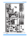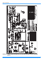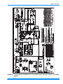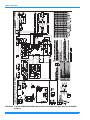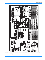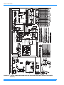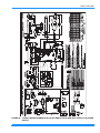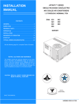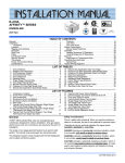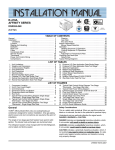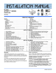
1
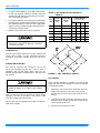
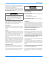
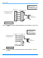
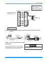
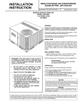
INSTALLATION MANUAL AFFINITY™ SERIES SINGLE PACKAGED GAS/ELECTRIC AIR COOLED AIR CONDITIONERS 2, 2-1/2, 3, 3-1/2, 4 AND 5 NOMINAL TON DNP024, 030, 036, 042, 048 & 060 CONTENTS INSTALLATION SAFETY INFORMATION . . . . . . . . 4 GENERAL . . . . . . . . . . . . . . . . . . . . . . . . . . . . . . . . . 4 INSPECTION . . . . . . . . . . . . . . . . . . . . . . . . . . . . . . . 4 MAINTENANCE . . . . . . . . . . . . . . . . . . . . . . . . . . . . . 4 RENEWAL PARTS . . . . . . . . . . . . . . . . . . . . . . . . . . 4 APPROVALS . . . . . . . . . . . . . . . . . . . . . . . . . . . . . . . 4 INSTALLATION . . . . . . . . . . . . . . . . . . . . . . . . . . . . . 5 SEQUENCE OF OPERATION . . . . . . . . . . . . . . . . . 17 START-UP . . . . . . . . . . . . . . . . . . . . . . . . . . . . . . . . 19 TYPICAL WIRING DIAGRAM NOTES . . . . . . . . . . 37 NOTES, CAUTIONS AND WARNINGS Installer should pay particular attention to the words: NOTE, CAUTION, and WARNING. Notes are intended to clarify or make the installation easier. Cautions are given to prevent equipment damage. Warnings are given to alert installer that personal injury and/or equipment damage may result if installation procedure is not handled properly. CAUTION: READ ALL SAFETY GUIDES BEFORE YOU BEGIN TO INSTALL YOUR UNIT. SAVE THIS MANUAL 280241-YIM-D-0909 280241-YIM-D-0909 TABLE OF CONTENTS INSTALLATION SAFETY INFORMATION . . . . . . . . GENERAL . . . . . . . . . . . . . . . . . . . . . . . . . . . . . . . . . INSPECTION . . . . . . . . . . . . . . . . . . . . . . . . . . . . . . . MAINTENANCE . . . . . . . . . . . . . . . . . . . . . . . . . . . . RENEWAL PARTS . . . . . . . . . . . . . . . . . . . . . . . . . . APPROVALS . . . . . . . . . . . . . . . . . . . . . . . . . . . . . . INSTALLATION . . . . . . . . . . . . . . . . . . . . . . . . . . . . 4 4 4 4 4 4 5 LIMITATIONS . . . . . . . . . . . . . . . . . . . . . . . . . . . . . . . . . . 5 LOCATION . . . . . . . . . . . . . . . . . . . . . . . . . . . . . . . . . . . . 5 CLEARANCES . . . . . . . . . . . . . . . . . . . . . . . . . . . . . . . . . 6 RIGGING OR HANDLING . . . . . . . . . . . . . . . . . . . . . . . . . 6 DUCT WORK . . . . . . . . . . . . . . . . . . . . . . . . . . . . . . . . . . 6 ROOF CURB . . . . . . . . . . . . . . . . . . . . . . . . . . . . . . . . . . . 7 FILTERS . . . . . . . . . . . . . . . . . . . . . . . . . . . . . . . . . . . . . . 7 CONDENSATE DRAIN . . . . . . . . . . . . . . . . . . . . . . . . . . . 7 SERVICE ACCESS . . . . . . . . . . . . . . . . . . . . . . . . . . . . . . 7 THERMOSTAT . . . . . . . . . . . . . . . . . . . . . . . . . . . . . . . . . 7 POWER AND CONTROL WIRING . . . . . . . . . . . . . . . . . . 7 COMPRESSORS . . . . . . . . . . . . . . . . . . . . . . . . . . . . . . . 9 GAS PIPING . . . . . . . . . . . . . . . . . . . . . . . . . . . . . . . . . . 12 GAS CONNECTION . . . . . . . . . . . . . . . . . . . . . . . . . . . . 12 FLUE VENT HOOD . . . . . . . . . . . . . . . . . . . . . . . . . . . . . 13 SEQUENCE OF OPERATION . . . . . . . . . . . . . . . . 17 HEATING . . . . . . . . . . . . . . . . . . . . . . . . . . . . . . . . . . . . 17 PRESSURE SWITCH PROVING . . . . . . . . . . . . . . . . . 17 PRE-PURGE . . . . . . . . . . . . . . . . . . . . . . . . . . . . . . . . 17 IGNITION TRIAL PERIOD . . . . . . . . . . . . . . . . . . . . . . 17 2 PILOT FLAME STABILIZATION PERIOD . . . . . . . . . . 17 HEAT BLOWER ON DELAY . . . . . . . . . . . . . . . . . . . . 17 MAIN BURNER OPERATION . . . . . . . . . . . . . . . . . . . 17 POST PURGE . . . . . . . . . . . . . . . . . . . . . . . . . . . . . . . 18 HEAT BLOWER OFF DELAY . . . . . . . . . . . . . . . . . . . 18 LOCKOUT . . . . . . . . . . . . . . . . . . . . . . . . . . . . . . . . . . 18 HIGH TEMPERATURE LIMIT SWITCH . . . . . . . . . . . 18 ROLLOUT SWITCH . . . . . . . . . . . . . . . . . . . . . . . . . . . 18 POWER INTERRUPTIONS . . . . . . . . . . . . . . . . . . . . . 18 FLAME PRESENT WITH GAS OFF . . . . . . . . . . . . . . 18 GAS VALVE STUCK OPEN OR CLOSED . . . . . . . . . 18 FLAME SENSE CIRCUIT FAILURE . . . . . . . . . . . . . . 18 SAFETY CONTROLS . . . . . . . . . . . . . . . . . . . . . . . . . 18 COOLING . . . . . . . . . . . . . . . . . . . . . . . . . . . . . . . . . . . . 19 CIRCULATING FAN . . . . . . . . . . . . . . . . . . . . . . . . . . . . 19 START-UP . . . . . . . . . . . . . . . . . . . . . . . . . . . . . . . 19 PRE-START CHECK LIST . . . . . . . . . . . . . . . . . . . . . . . OPERATING INSTRUCTIONS . . . . . . . . . . . . . . . . . . . . TO TURN OFF GAS TO UNIT . . . . . . . . . . . . . . . . . . . . POST-START CHECK LIST (GAS) . . . . . . . . . . . . . . . . MANIFOLD GAS PRESSURE ADJUSTMENT . . . . . . . . BURNER INSTRUCTIONS . . . . . . . . . . . . . . . . . . . . . . . PILOT INSTRUCTIONS . . . . . . . . . . . . . . . . . . . . . . . . . ADJUSTMENT OF TEMPERATURE RISE . . . . . . . . . . DIRECT DRIVE BLOWER . . . . . . . . . . . . . . . . . . . . . . CHECKING GAS INPUT . . . . . . . . . . . . . . . . . . . . . . . . NATURAL GAS . . . . . . . . . . . . . . . . . . . . . . . . . . . . . . 19 19 20 20 20 21 21 21 21 22 22 TYPICAL WIRING DIAGRAM NOTES . . . . . . . . . . 37 Johnson Controls Unitary Products 280241-YIM-D-0909 LIST OF FIGURES Fig. # 1 2 3 4 5 6 7 8 9 10 11 12 13 14 15 16 17 18 19 20 Pg. # PRODUCT NOMENCLATURE . . . . . . . . . . . . . . . . . . . 5 UNIT CENTER OF GRAVITY . . . . . . . . . . . . . . . . . . . . 6 TYPICAL FIELD CONTROL WIRING DIAGRAM SINGLE STAGE THERMOSTAT - SINGLE STAGE GAS HEAT . . . . . . . . . . . . . . . . . . . . . . . . . . . . . . . . . . 8 TYPICAL FIELD CONTROL WIRING DIAGRAM SINGLE STAGE THERMOSTAT - TWO STAGE GAS HEAT . . . . . . . . . . . . . . . . . . . . . . . . . . . . . . . . . . 8 TYPICAL FIELD CONTROL WIRING DIAGRAM TWO STAGE THERMOSTAT - TWO STAGE GAS HEAT . . . . . . . . . . . . . . . . . . . . . . . . . . . . . . . . . . 9 TYPICAL FIELD POWER WIRING DIAGRAM . . . . . . . 9 ROTARY COMPRESSOR MOUNTING . . . . . . . . . . . 10 EXTERNAL SUPPLY CONNECTION EXTERNAL SHUT-OFF . . . . . . . . . . . . . . . . . . . . . . . . . . . . . . . . . 12 FLUE VENT OUTLET AIR HOOD . . . . . . . . . . . . . . . 13 UNIT DIMENSIONS - FRONT . . . . . . . . . . . . . . . . . . 15 UNIT DIMENSIONS - FRONT & BOTTOM . . . . . . . . 16 UNIT DIMENSIONS - BACK & BOTTOM . . . . . . . . . . 16 SINGLE STAGE GAS VALVE - FRONT . . . . . . . . . . 20 TWO STAGE GAS VALVE - FRONT . . . . . . . . . . . . . 20 SINGLE STAGE GAS VALVE - REAR . . . . . . . . . . . . 20 TWO STAGE GAS VALVE - REAR . . . . . . . . . . . . . . 20 PROPER FLAME ADJUSTMENT . . . . . . . . . . . . . . . 21 TYPICAL WIRING DIAGRAM D*NP 024 SINGLE STAGE GAS HEAT (208/230-1-60 POWER SUPPLY) . . . . . . 23 TYPICAL WIRING DIAGRAM D*NP 024 TWO STAGE GAS HEAT (208/230-1-60 POWER SUPPLY) . . . . . . 24 TYPICAL WIRING DIAGRAM D*NP 030-048 SINGLE STAGE GAS HEAT (208/230-1-60 POWER SUPPLY) . . . . . . . . . . . . . . . . . . . . . . . . . . . . . . . . . . 25 Fig. # Pg. # 21 TYPICAL WIRING DIAGRAM D*NP 030-048 TWO STAGE GAS HEAT (208/230-1-60 POWER SUPPLY) . . . . . . . . . . . . . . . . . . . . . . . . . . . . . . . . . . 26 22 TYPICAL WIRING DIAGRAM D*NP 060 SINGLE STAGE (208/230-1-60 POWER SUPPLY) . . . . . . . . . . . . . . . 27 23 TYPICAL WIRING DIAGRAM D*NP 060 TWO STAGE (208/230-1-60 POWER SUPPLY) . . . . . . . . . . . . . . . 28 24 TYPICAL WIRING DIAGRAM D*NP 030-048 SINGLE STAGE GAS HEAT (208/230-3-60 POWER SUPPLY) . . . . . . . . . . . . . . . . . . . . . . . . . . . . . . . . . . 29 25 TYPICAL WIRING DIAGRAM D*NP 030-048 TWO STAGE GAS HEAT (208/230-3-60 POWER SUPPLY) . . . . . . . . . . . . . . . . . . . . . . . . . . . . . . . . . . 30 26 TYPICAL WIRING DIAGRAM D*NP 060 SINGLE STAGE GAS HEAT (208/230-3-60 POWER SUPPLY) . . . . . 31 27 TYPICAL WIRING DIAGRAM D*NP 060 TWO STAGE GAS HEAT (208/230-3-60 POWER SUPPLY) . . . . . 32 28 TYPICAL WIRING DIAGRAM D*NP 030-048 SINGLE STAGE GAS HEAT (460/575-3-60 POWER SUPPLY) . . . . . . . . . . . . . . . . . . . . . . . . . . . . . . . . . . 33 29 TYPICAL WIRING DIAGRAM D*NP 030-048 TWO STAGE GAS HEAT (460/575-3-60 POWER SUPPLY) . . . . . . . . . . . . . . . . . . . . . . . . . . . . . . . . . . 34 30 TYPICAL WIRING DIAGRAM D*NP 060 SINGLE STAGE GAS HEAT (460/575-3-60 POWER SUPPLY) . . . . . . . . . . . . . . . . . . . . . . . . . . . . . . . . . . 35 31 TYPICAL WIRING DIAGRAM D*NP 060 TWO STAGE GAS HEAT (460/575-3-60 POWER SUPPLY) . . . . . 36 32 TYPICAL WIRING DIAGRAM LEGEND . . . . . . . . . . 37 LIST OF TABLES Tbl. # 1 2 3 4 5 6 Pg. # UNIT APPLICATION DATA . . . . . . . . . . . . . . . . . . . . . . 5 UNIT WEIGHTS AND CENTER OF GRAVITY . . . . . . . 6 NATURAL GAS APPLICATION DATA - SINGLE STAGE . . . . . . . . . . . . . . . . . . . . . . . . . . . . . . . . . . . . . 10 NATURAL GAS APPLICATION DATA - TWO STAGE . . . . . . . . . . . . . . . . . . . . . . . . . . . . . . . . . . . . . 10 PROPANE (LP) GAS APPLICATION DATA - SINGLE STAGE . . . . . . . . . . . . . . . . . . . . . . . . . . . . . . . . . . . . . 11 PROPANE GAS APPLICATION DATA - TWO STAGE . . . . . . . . . . . . . . . . . . . . . . . . . . . . . . . . . . . . . 11 Johnson Controls Unitary Products Tbl. # 7 8 9 10 11 12 13 14 Pg. # NATURAL GAS PIPE SIZING CHART . . . . . . . . . . . . PROPANE (LP) GAS PIPE SIZING CHART . . . . . . . . PHYSICAL DATA . . . . . . . . . . . . . . . . . . . . . . . . . . . . ELECTRICAL DATA . . . . . . . . . . . . . . . . . . . . . . . . . . UNIT DIMENSIONS FRONT . . . . . . . . . . . . . . . . . . . . UNIT MINIMUM CLEARANCES . . . . . . . . . . . . . . . . IGNITION CONTROL BOARD FLASH CODES . . . . . GAS RATE - CUBIC FEET PER HOUR . . . . . . . . . . . 12 12 14 14 15 15 19 22 3 280241-YIM-D-0909 INSTALLATION SAFETY INFORMATION INSPECTION Read these instructions before continuing this appliance installation. This is an outdoor combination heating and cooling unit. The installer must assure that these instructions are made available to the consumer and instruct the consumer to retain them for future reference. As soon as a unit is received, it should be inspected for possible damage during transit. If damage is evident, the extent of the damage should be noted on the carrier's freight bill. A separate request for inspection by the carrier's agent should be made in writing. 1. Refer to the furnace rating plate for the approved type of gas for this furnace. MAINTENANCE 2. Install this furnace only in a location and position as specified on pages 5 and 6 of these instructions. Refer to User’s, Maintenance and Service Information Manual, Part No. 291891. 3. Never test for gas leaks with an open flame. Use commercially available soap solution made specifically for the detection of leaks when checking all connections, as specified on pages 4 and 13 of these instructions. RENEWAL PARTS 4. 5. Always install furnace to operate within the furnace’s intended temperature-rise range with the duct system and within the allowable external static pressure range, as specified on the unit name/rating plate, specified on pages 10, 11 and 21 of these instructions. This equipment is not to be used for temporary heating of buildings or structures under construction. Contact your local York® parts distribution center for authorized replacement parts. APPROVALS Design certified by CSA listed as follows: 1. For use as a forced air furnace with cooling unit. 2. For outdoor installation only. 3. For installation directly on combustible flooring or, in U.S., on wood flooring or Class A; B; C roof covering material. 4. For installation on combustible material. 5. For use with natural gas and/or propane (LP) gas. FIRE OR EXPLOSION HAZARD Failure to follow the safety warnings exactly could result in serious injury, death or property damage. Never test for gas leaks with an open flame. Use a commercially available soap solution made specifically for the detection of leaks to check all connections. A fire or explosion may result causing property damage, personal injury or loss of life. GENERAL YORK Model DNP units are cooling/heating air conditioners designed for outdoor installation. Only gas piping, electric power and duct connections are required at the point of installation. Not suitable for use with conventional venting systems. This product must be installed in strict compliance with the enclosed installation instructions and any applicable local, state, and national codes including but not limited to, building, electrical and mechanical codes. The single or two stage gas-fired heaters have spark to pilot ignition. The tubular heat exchangers are aluminized steel. Installer should pay particular attention to the words; NOTE, CAUTION, and WARNING. NOTES are intended to clarify or make the installation easier. CAUTIONS are given to prevent equipment damage. WARNINGS are given to alert the installer that personal injury and/or equipment damage may result if installation procedure is not handled properly. 4 Improper installation may create a condition where the operation of the product could cause personal injury or property damage. Johnson Controls Unitary Products 280241-YIM-D-0909 INSTALLATION 4. LIMITATIONS Refer to Table 1 for unit application data and to Tables 3 thru 6 for gas heat application data. These units must be installed in accordance with the following national and local safety codes. 1. National Electrical Code ANSI/NFPS No. 70 or Canadian Electrical Code Part 1, C22.1 (latest editions). 2. National Fuel Gas Code Z223.1 or CSA B149.1 Installation Code. 3. Local gas utility requirements. D 1 N P 0 Local plumbing and waste water codes and other applicable local codes. If components are to be added to a unit to meet local codes, they are to be installed at the dealer's and/or the customer's expense. Size of unit for proposed installation should be based on heat loss/heat gain calculations made in accordance with industry recognized procedures identified by the Air Conditioning Contractors of America. 3 6 N 0 3 6 0 6 PRODUCT CATEGORY VOLTAGE CODE D = Single Package Air Conditioner 06 = 208/230-1-60 25 = 208/230-3-60 46 = 460-3-60 58 = 575-3-60 PRODUCT GENERATION 1 = 1st Generation 2 = 2nd Generation 3 = 3rd Generation NOMINAL HIGH GAS HEAT OUTPUT CAPACITY (NOMINAL LOW GAS HEAT OUTPUT CAPACITY) PRODUCT IDENTIFIER NP = 13 SEER Gas Heat/Electric FACTORY INSTALLED NATURAL GAS HEAT NOMINAL COOLING CAPACITY (MBH) 024 = 24,000 BTUH 030 = 30,000 BTUH 036 = 36,000 BTUH 042 = 42,000 BTUH 048 = 48,000 BTUH 060 = 60,000 BTUH N = Single Stage D = Two Stage 036 = 36,000 BTUH 056 = 56,000 BTUH (36,400 BTUH) 065 = 65,000 BTUH 072 = 72,000 BTUH (46,800 BTUH) 090 = 90,000 BTUH (56,160 BTUH) 110 = 110,000 BTUH (70,200 BTUH) FIGURE 1 - PRODUCT NOMENCLATURE TABLE 1: UNIT APPLICATION DATA Voltage Variation Min. / Max.1 208/230V2 187 / 252 460V 432 / 504 575V 540 / 630 Wet Bulb Temperature (°F) of Air on Evaporator Coil, Min. / Max. Dry Bulb Temperature (°F) of Air on Condenser Coil, Min.3 / Max. 1. Unit is designed for outdoor installation only. 2. Condenser must have an unlimited supply of air. Where a choice of location is possible, position unit on either north or east side of building. 57 / 72 45 / 120 1. Rated in accordance with ARI Standard 110, utilization range “A”. 2. “T1” transformer primary tap must be moved from the 230 volt connection to the 208 volt connection for low voltage applications of 208 volt and below 3. A low ambient accessory is available for operation down to 0 °F. LOCATION Excessive exposure of this furnace to contaminated combustion air may result in equipment damage or personal injury. Typical contaminates include: permanent wave solution, chlorinated washes and cleaners, chlorine based swimming pool chemicals, water softening chemicals, carbon tetrachloride, halogen type refrigerants, cleaning solvents (e.g. perchloroethylene), printing inks, paint removers, varnishes, hydrochloric acid, cements and glues, antistatic fabric softeners for clothes dryers, masonry acid washing materials. Use the following guidelines to select a suitable location for these units. Johnson Controls Unitary Products 5 280241-YIM-D-0909 3. 4. 5. For ground level installation, a level pad or slab should be used. The thickness and size of the pad or slab used should meet local codes and unit weight. Do not tie the slab to the building foundation. For roof top installation, be sure the structure will support the weight of the unit plus any field installed components. Unit must be installed on a level roof curb or appropriate angle iron frame providing adequate support under the compressor/condenser section. TABLE 2: UNIT WEIGHTS AND CENTER OF GRAVITY SHIPPING WEIGHT (LBS.) OPERATING WEIGHT (LBS.) 024 365 030 UNIT SIZE Maintain level tolerance of unit to 1/8" maximum. “A” “B” “C” “D” 360 91 88 89 92 395 390 98 95 96 99 036 400 395 100 96 98 101 042 470 465 131 129 101 103 048 475 470 133 130 102 104 060 485 480 136 133 105 107 Do not permit overhanging structures or shrubs to obstruct the condenser air discharge, combustion air inlet or vent outlet. "D" CENTER OF GRAVITY FRONT OF UNIT CLEARANCES All units require certain clearances for proper operation and service. Refer to Table 12 for the clearances required for combustion, construction, servicing and proper unit operation. "A" RIGGING OR HANDLING 49-1/8 Care must be exercised when moving the unit. Do not remove any packaging until the unit is near the place of installation. Rig unit with slings placed under the unit. Spreader bars of sufficient length should be used across the top of the unit. CORNER WEIGHTS (LOCATION, LBS.) "C" 25 "B" 25 47-1/4 FIGURE 2 - UNIT CENTER OF GRAVITY DUCT WORK Before lifting a unit, make sure that its weight is distributed equally on the cables so that it will lift evenly. Units may also be moved or lifted with a fork-lift. Slotted openings in the skid are provided for this purpose. Forks must pass completely through the base. These units are adaptable to downflow use as well as rear supply and return air duct openings. To convert to downflow, use the following steps: 1. Remove the duct covers found in the bottom return and supply air duct openings. There are four (4) screws securing each duct cover (save these screws to use in Step 2). 2. Install the duct covers (removed in step one) to the rear supply and return air duct openings. Secure with the four (4) screws used in step one. 3. Seal duct covers with silicone caulk. Refer to Table 2 for unit weights and to Figure 2 for approximate center of gravity. 6 Johnson Controls Unitary Products 280241-YIM-D-0909 Duct work should be designed and sized according to the methods of the Air Conditioning Contractors of America (ACCA), as set forth in their Manual D. A closed return duct system shall be used. This shall not preclude use of economizers or ventilation air intake. Flexible joints may be used in the supply and return duct work to minimize the transmission of noise. Hand tighten only. SERVICE ACCESS Access to all serviceable components is provided by the following removable panels: When fastening duct work to the side duct flanges on the unit, insert the screws through the duct flanges only. Do not insert the screws through the casing. Outdoor ductwork must be insulated and waterproofed. • • Blower compartment Gas control/electrical service access Refer to Figure 10 for location of these access panels and minimum clearances in Table 12. NOTE: Be sure to note supply and return openings. THERMOSTAT Refer to Figures 11 and 12 for information concerning rear and bottom supply and return air duct openings. The room thermostat should be located on an inside wall approximately 56" above the floor where it will not be subject to drafts, sun exposure or heat from electrical fixtures or appliances. Follow manufacturer's instructions enclosed with the thermostat for general installation procedure. Color coded insulated wires (minimum #18 AWG) should be used to connect thermostat to unit. See Figures 3 thru 5. ROOF CURB On applications when a roof curb is used, the unit must be positioned on the curb so the front of the unit is tight against the curb. FILTERS Single phase units are shipped without a filter or filter racks. It is the responsibility of the installer to secure a filter in the return air ductwork or install a Filter/Frame Kit (1FF0110 for 2 thru 3½ ton units or 1FF0112 for 4 thru 5 ton units). A filter rack and high velocity filters are standard on three phase units. POWER AND CONTROL WIRING Field wiring to the unit must conform to provisions of the current N.E.C. ANSI/NFPA No. 70 or C.E.C. and/or local ordinances. The unit must be electrically grounded in accordance with local codes or, in their absence, with the N.E.C./C.E.C. Voltage tolerances which must be maintained at the compressor terminals during starting and running conditions are indicated on the unit Rating Plate and Table 10. Filters must always be used and must be kept clean. When filters become dirt laden, insufficient air will be delivered by the blower, decreasing your units efficiency and increasing operating costs and wear-and-tear on the unit and controls. The wiring entering the cabinet must be provided with mechanical strain relief. Filters should be checked monthly; this is especially important since this unit is used for both heating and cooling. A fused disconnect switch should be field provided for the unit. If any of the wire supplied with the unit must be replaced, replacement wire must be of the type shown on the wiring diagram. CONDENSATE DRAIN A condensate trap is recommended to be installed in the condensate drain. The plumbing must conform to local codes. Use a sealing compound on male pipe threads. Install the condensate drain line (NPTF) to spill into an open drain. Johnson Controls Unitary Products Electrical line must be sized properly to carry the load. Each unit must be wired with a separate branch circuit fed directly from the meter panel and properly fused. Refer to Figure 6 for typical field wiring and to the appropriate unit wiring diagram for control circuit and power wiring information. 7 280241-YIM-D-0909 NOTE: HEAT ANTICIPATOR SHOULD BE SET AT 0.35 AMPS FOR ALL MODELS. THERMOSTAT ** = Minimum wire size of 18 AWG wire should be used for all field installed 24 volt wire. UNIT TERMINAL STRIP ** R R G G Y Y W W C C 24 VOLT TRANSFORMER PROGRAMMABLE THERMOSTAT ONLY FIGURE 3 - TYPICAL FIELD CONTROL WIRING DIAGRAM SINGLE STAGE THERMOSTAT - SINGLE STAGE GAS HEAT NOTE: HEAT ANTICIPATOR SHOULD BE SET AT 0.35 AMPS FOR ALL MODELS. THERMOSTAT UNIT TERMINAL STRIP ** = Minimum wire size of 18 AWG wire should be used for all field installed 24 volt wire. R ** R G G Y Y W W1 24 VOLT TRANSFORMER W2 C C PROGRAMMABLE THERMOSTAT ONLY FIGURE 4 - TYPICAL FIELD CONTROL WIRING DIAGRAM SINGLE STAGE THERMOSTAT - TWO STAGE GAS HEAT 8 Johnson Controls Unitary Products 280241-YIM-D-0909 NOTE: HEAT ANTICIPATOR SHOULD BE SET AT 0.35 AMPS FOR ALL MODELS. THERMOSTAT ** = Minimum wire size of 18 AWG wire should be used for all field installed 24 volt wire. UNIT TERMINAL STRIP ** R R G G Y1 Y 24 VOLT TRANSFORMER Y2 W1 W1 W2 W2 C C PROGRAMMABLE THERMOSTAT ONLY FIGURE 5 - TYPICAL FIELD CONTROL WIRING DIAGRAM TWO STAGE THERMOSTAT - TWO STAGE GAS HEAT C O N T A C T O R C O N T A C T O R F IE L D -S U P P L IE D D IS C O N N E C T G R O U N D L U G R E F E R T O E L E C T R IC A L D A T A T A B L E S T O S IZ E T H E D IS C O N N E C T S IN P H P O S U G L E A S E W E R P P L Y F IE L D -S U P P L IE D D IS C O N N E C T G R O U N D L U G R E F E R T O E L E C T R IC A L D A T A T A B L E S T O S IZ E T H E D IS C O N N E C T T H R P H A P O W S U P E E S E E R P L Y FIGURE 6 - TYPICAL FIELD POWER WIRING DIAGRAM COMPRESSORS Units with rotary compressors must have compressor mountings adjusted. Refer to Figure 7 for rotary compressor mounting specifications. All other unit compressor mountings are factory-adjusted and are ready for operation. Johnson Controls Unitary Products Do not loosen compressor mounting bolts, except on rotary compressors. 9 280241-YIM-D-0909 MOUNTING STUD NUT (There must be clearance between Grommet & Nut) 0.02 – 0.08 in. (0.5 – 2mm) COMPRESSOR BASE GROMMET UNIT CHASSIS FIGURE 7 - ROTARY COMPRESSOR MOUNTING TABLE 3: NATURAL GAS APPLICATION DATA - SINGLE STAGE TEMP. RISE ºF AT GAS RATE2 (MBH)1 OUTPUT (MBH) FT.3/HR. NUMBER OF BURNERS MIN. MAX. 2, 2-1/2, 3 TON 45 36 42 2 25 55 2, 2-1/2 TON 70 56 65 3 30 60 3 TON 70 56 65 3 25 55 3-1/2, 4, 5 TON 80 64 74 3 25 55 AVAILABLE ON MODELS INPUT FULL INPUT3 3 TON 90 72 84 4 30 60 3-1/2 TON 108 87 100 4 45 75 4, 5 TON 108 87 100 4 35 65 4, 5 TON 135 108 126 5 45 75 1. Heating capacity valid for elevations up to 2000 feet above sea level. For elevations above 2,000 feet, rated capacity should be reduced by 4% for each 1,000 feet above sea level. 2. Based on 1075 BTU/Ft.3. 3. The air flow must be adequate to obtain a temperature rise within the range shown. Continuous return air temperature should not be below 55°F. TABLE 4: NATURAL GAS APPLICATION DATA - TWO STAGE INPUT (MBH)1 HIGH FIRE / LOW FIRE OUTPUT (MBH) HIGH FIRE/LOW FIRE 2, 2-1/2 TON 70 / 45.5 3 TON 3 TON AVAILABLE ON MODELS TEMP. RISE ºF AT GAS RATE2 FT.3/HR. HIGH FIRE/LOW FIRE NUMBER OF BURNERS 56 / 36.4 65 / 42 70 / 45.5 56 / 36.4 90 / 58.5 72 / 46.8 FULL INPUT3 MIN. MAX. 3 30 60 65 / 42 3 25 55 84 / 54 4 30 60 4, 5 TON 108 / 70.2 87 / 56.2 100 / 65 4 35 65 4, 5 TON 135 / 87.75 108 / 70.2 126 / 82 5 45 75 1. Heating capacity valid for elevations up to 2000 feet above sea level. For elevations above 2,000 feet, rated capacity should be reduced by 4% for each 1,000 feet above sea level. 2. Based on 1075 BTU/Ft.3. 3. The air flow must be adequate to obtain a temperature rise within the range shown. Continuous return air temperature should not be below 55°F. 10 Johnson Controls Unitary Products 280241-YIM-D-0909 TABLE 5: PROPANE1 (LP) GAS APPLICATION DATA - SINGLE STAGE AVAILABLE ON MODELS 2, 2-1/2, 3 TON INPUT (MBH)2 45 OUTPUT (MBH) TEMP. RISE ºF AT GAS RATE3 FT.3/HR. NUMBER OF BURNERS 18 2 36 FULL INPUT4 MIN. MAX. 25 55 2, 2-1/2 TON 70 56 28 3 30 60 3 TON 70 56 28 3 25 55 3-1/2, 4, 5 TON 80 64 32 3 25 55 3 TON 90 72 36 4 30 60 3-1/2 TON 108 87 43 4 45 75 4, 5 TON 108 87 43 4 35 65 4, 5 TON 135 108 54 5 45 75 1. Propane applications are accomplished by field installation of a Propane Conversion Accessory, Model 1NP0807 for 2 thru 3 Ton units with 33-1/2” tall cabinets and Model 1NP0808 for 3-1/2 thru 5 Ton units with 41-1/2” tall cabinets. 2. Heating capacity valid for elevations up to 2,000 feet above sea level. For elevations above 2,000 feet, rated capacity should be reduced by 4% for each 1,000 feet above sea level. 3. Based on 2500 BTU/Ft.3. 4. The air flow must be adequate to obtain a temperature rise within the range shown. Continuous return air temperatures should not be below 55°F. TABLE 6: PROPANE1 GAS APPLICATION DATA - TWO STAGE TEMP. RISE ºF AT AVAILABLE ON MODELS INPUT (MBH)2 HIGH FIRE / LOW FIRE OUTPUT (MBH) HIGH FIRE/LOW FIRE GAS RATE3 FT.3/HR. HIGH FIRE/LOW FIRE NUMBER OF BURNERS MIN. MAX. 2, 2-1/2TON 70 / 45.5 56 / 36.4 28 / 18.2 3 30 60 3 TON 70 / 45.5 56 / 36.4 28 / 18.2 3 25 55 3 TON 90 / 58.5 72 / 46.8 36 / 23.4 4 30 60 FULL INPUT4 4, 5 TON 108 / 70.2 87 / 56.2 43 / 27.95 4 35 65 4, 5 TON 135 / 87.75 108 / 70.2 54 / 35.1 5 45 75 1. Propane applications are accomplished by field installation of a Propane Conversion Accessory, Model 1NP0809 for 2 thru 3 Ton units with 33-1/2” tall cabinets and Model 1NP0810 for 4 and 5 Ton units with 41-1/2” tall cabinets. 2. Heating capacity valid for elevations up to 2000 feet above sea level. For elevations above 2,000 feet, rated capacity should be reduced by 4% for each 1,000 feet above sea level. 3. Based on 2500 BTU/Ft.3. 4. The air flow must be adequate to obtain a temperature rise within the range shown. Continuous return air temperature should not be below 55°F. Johnson Controls Unitary Products 11 280241-YIM-D-0909 GAS PIPING TABLE 7: NATURAL GAS PIPE SIZING CHART1 Proper sizing of gas piping depends on the cubic feet per hour of gas flow required, specific gravity of the gas and the length of run. National Fuel Gas Code Z223.1 or CSA B149.1 should be followed in all cases unless superseded by local codes or gas company requirements. Refer to Tables 7 & 8. LENGTH IN FEET NOMINAL INCHES IRON PIPE SIZE 1/2” 3/4” 1” 1-1/4” 10 132 278 520 1,050 The heating value of the gas may differ with locality. The value should be checked with the local gas utility. 20 92 190 350 730 30 73 152 285 590 NOTE: There may be a local gas utility requirement specifying a minimum diameter for gas piping. All units require a 1/2 inch pipe connection at the gas valve. 40 63 130 245 500 50 56 115 215 440 GAS CONNECTION 60 50 105 195 400 70 46 96 180 370 80 43 90 170 350 90 40 84 160 320 100 38 79 150 305 The gas supply line can be routed through the hole located on the left side of the unit. Refer to Figure 10 to locate these access openings. Typical supply piping arrangements are shown in Figure 8. Gas piping requirements: 1. A drip leg and a ground joint union must be installed in the gas piping. 2. When required by local codes, a manual shut-off valve may have to be installed outside of the unit. 3. Use wrought iron or steel pipe for all gas lines. Pipe dope should be applied sparingly to male threads only. 1. Maximum capacity of pipe in cubic feet of gas per hour (based upon a pressure drop of 0.3 inch water column and 0.6 specific gravity gas). TABLE 8: PROPANE (LP) GAS PIPE SIZING CHART1 LENGTH IN FEET AUTOMATIC GAS VALVE 1/2” x 1/2” UNION 1/2” x 1/2” GAS COCK NOMINAL INCHES IRON PIPE SIZE 1/2” 3/4” 1” 1-1/4” 10 275 567 1,071 2,205 20 189 393 732 1,496 30 152 315 590 1,212 40 129 267 504 1,039 50 114 237 448 913 60 103 217 409 834 70 96 196 378 771 80 89 185 346 724 90 83 173 322 677 100 78 162 307 630 1/2” - NPTF DRIP LEG FIGURE 8 - EXTERNAL SUPPLY CONNECTION EXTERNAL SHUT-OFF 12 1. Maximum capacity of pipe in thousands of BTU per hour (based upon a pressure drop of 0.5 inch water column). Johnson Controls Unitary Products 280241-YIM-D-0909 FLUE VENT HOOD If flexible stainless steel tubing is allowed by the authority having jurisdiction, wrought iron or steel pipe must be installed at the gas valve and extend a minimum of two (2) inches outside of the unit casing. The flue vent hood with screen is shipped loose. This hood must be installed to assure proper unit operation. The hood must be fastened to the outside of the side gas control/electrical compartment with the screws provided in the bag attached to the inside of the gas control/electrical compartment, see Figure 9. Flue hood surfaces may be hot. Natural gas may contain some propane. Propane being a excellent solvent, will quickly dissolve white lead or most standard commercial compounds. Therefore, a special pipe dope must be applied when wrought iron or steel pipe is used. Shellac base compounds such as Gaskoloc or Stalastic, and compounds such as Rectorseal # 5, Clyde’s or John Crane may be used. 4. All piping should be cleaned of dirt and scale by hammering on the outside of the pipe and blowing out the loose dirt and scale. Before initial start-up, be sure that all of the gas lines external to the unit have been purged of air. 5. The gas supply should be a separate line and installed in accordance with all safety codes as prescribed under Limitations, shown on Page 5. After the gas connections have been completed, open the main shut-off valve admitting normal gas pressure to the mains. Check all joints for leaks with soap solution or other material suitable for the purpose. NEVER USE A FLAME. 6. The furnace must be isolated from the gas supply piping system by closing its individual manual shut-off valve before conducting any pressure testing of the gas supply piping system at test pressures equal to or less than 1/2 psig (3.48 kPa). Johnson Controls Unitary Products V E N T O U T L E T S C R E E N F L U E V E N T O U T L E T A IR H O O D FIGURE 9 - FLUE VENT OUTLET AIR HOOD The flue exhaust hood must be properly installed and within the recommended clearances. Further communications and action must be given to the home or building owner(s) to eliminate any unauthorized human contact around this area during the heating cycle. Flue hood surface and the immediate area reach high temperatures during the heating cycle. 13 280241-YIM-D-0909 TABLE 9: PHYSICAL DATA DNP MODEL CENTRIFUGAL BLOWER EVAPORATOR (Dia. x W. in.) BLOWER FAN MOTOR HP 024 030 - 1Ø 030 - 3Ø 036 042 048 060 10 x 8 10 x 8 10 x 8 11 x 10 12 x 11 12 x 11 12 x 11 1/2 3/4 3/4 3/4 1 1 1 2 3 3 3 3 3 3 15 13 13 13 13 16 16 3.5 3.5 3.5 3.5 4.5 4.5 4.5 ROWS DEEP EVAPORATOR FINS PER INCH COIL FACE AREA (Sq. Ft.) PROPELLER DIA. (in.) CONDENSER FAN MOTOR HP FAN NOM. CFM TOTAL 22 22 22 22 22 22 22 1/4 1/4 1/4 1/4 1/4 1/3 1/3 2,200 2,400 2,400 2,400 2,400 3,000 3,500 2 1 1 2 2 2 2 ROWS DEEP CONDENSER FINS PER INCH COIL FACE AREA (Sq. Ft.) CHARGE FILTER FURNACE SECTION REFRIGERANT 22 (lbs./oz.) FACE AREA (Sq. Ft.) Size (Actual) 20 20 20 20 20 20 20 11.7 11.7 11.7 11.7 14.7 14.7 14.7 6/4 5/4 4/9 6 / 12 9/6 8/4 8/8 3.1 / 19.5 x 11.5 3.1 / 19.5 x 11.5 3.1 / 19.5 x11.5 2.6 / 19 x 19.5 2.6 / 19 x 19.5 2.6 / 19 x 19.5 2.6 / 19 x 19.5 (2 Reqd.) (2 Reqd.) (2 Reqd.) NATURAL GAS BURNER ORIFICE NO. (Drill Size) 43 43 43 43 40 40 40 PROPANE BURNER ORIFICE NO. (Drill Size) 55 55 55 55 53 53 53 1/2 NPTF 1/2 NPTF 1/2 NPTF 1/2 NPTF 1/2 NPTF 1/2 NPTF 1/2 NPTF Recip Rotary Scroll Scroll Recip Scroll Scroll GAS CONNECTION SIZE COMPRESSOR HERMETIC TYPE, (Qty. = 1) TABLE 10: ELECTRICAL DATA VOLTAGE LIMITATIONS1 SUPPLY AIR BLOWER MOTOR FLA MINIMUM CIRCUIT AMPACITY MAX. FUSE SIZE, AMPS2 MAX. HACR BREAKER SIZE, AMPS UNIT POWER FACTOR TRANSFORMER SIZE (VA) MIN. MAX. RLA LRA COND. FAN MOTOR, FLA 208/230-1-60 187 253 10.2 54 1.2 2.6 16.6 20 20 0.96 40 208/230-1-60 187 253 10.9 68 1.2 6.0 20.8 25 25 0.96 40 030 208/230-3-60 187 253 7.7 55 1.2 6.0 16.8 20 20 0.96 75 030 460-3-60 432 504 3.8 27 0.6 3.0 8.4 15 15 0.96 75 036 208/230-1-60 187 253 15.4 88 1.2 6.0 26.5 35 35 0.96 40 036 208/230-3-60 187 253 10.2 77 1.2 6.0 20 25 25 0.96 75 036 460-3-60 432 504 5.1 39 0.8 3.0 10.1 15 15 0.96 75 036 575-3-60 540 630 4.2 31 0.6 2.4 8.3 15 15 0.96 75 042 208/230-1-60 187 253 16.2 86 1.2 7.6 29.1 35 35 0.96 40 042 208/230-3-60 187 253 11.5 88 1.2 7.6 23.2 30 30 0.96 75 042 460-3-60 432 504 5.8 42 0.8 3.8 11.8 15 15 0.96 75 042 575-3-60 540 630 5.1 36 0.6 3.0 10.0 15 15 0.96 75 048 208/230-1-60 187 253 23.4 126 1.7 7.6 38.6 50 50 0.96 40 048 208/230-3-60 187 253 12.9 93 1.7 7.6 25.4 35 35 0.96 75 048 460-3-60 432 504 6.4 46.5 1.0 3.8 12.8 15 15 0.96 75 048 575-3-60 540 630 5.1 37 0.8 3.0 10.2 15 15 0.96 75 060 208/230-1-60 187 253 25.0 150 2.8 7.6 41.7 50 50 0.96 40 060 208/230-3-60 187 253 17.3 123 2.8 7.6 32.0 40 40 0.96 75 060 460-3-60 432 504 8.4 70 1.4 3.8 15.7 20 20 0.96 75 060 575-3-60 540 630 7.0 53 1.2 3.0 13.0 15 15 0.96 75 MODEL DNP POWER SUPPLY 024 030 COMPRESSOR 1. Rated in accordance with ARI Standard 110, utilization range “A”. 2. Dual element, time delay type. 14 Johnson Controls Unitary Products 280241-YIM-D-0909 VENT AIR OUTLET HOOD GAS SUPPLY 1-1/4" DIA. HOLE (1/2" NPTF CONNECTION) BLOWER SERVICE ACCESS COMPARTMENT PANEL CONDENSER COIL UNIT CONDENSATE CONNECTION 3/4" NPTF (TRAP RECOMMENDED) A 2-3/8 B HIGH VOLTAGE CONN. 1-3/8" DIA. KNOCKOUT HIGH VOLTAGE CONN. 7/8" DIA. KNOCKOUT 3-3/4 REFRIGERANT CONNECTIONS 2-1/2 COMBUSTION AIR INLET LOUVERS GAS SUPPLY 1-1/4" DIA. KNOCKOUT (1/2" NPTF CONNECTION) FRONT LOW VOLTAGE CONN. 1-3/8" DIA. KNOCKOUT X 7/8" HOLE 5-3/8 1-1/2 11 47-1/4 (OVERALL) 3-1/3 12-3/4 GAS/ELECTRIC CONTROL SERVICE ACCESS (OVERALL) COMPARTMENT PANEL 49-1/8 2-5/8 FIGURE 10 - UNIT DIMENSIONS - FRONT TABLE 11: UNIT DIMENSIONS FRONT UNIT SIZE 024, 030, 036 042, 048, 060 DIMENSION “A” 33-1/2 41-1/2 “B” 18-1/4 23-1/8 TABLE 12: UNIT MINIMUM CLEARANCES1 2 CLEARANCES FRONT BACK LEFT SIDE (Filter-Access) RIGHT SIDE 36” 0” 24” 12” BELOW UNIT3 0” ABOVE UNIT 4 36” (For Condenser Air Discharge 1. A 1” clearance must be provided between any combustible material and the supply air ductwork. 2. The products of combustion must not be allowed to accumulate within a confined space and recirculate. 3. Units may be installed on combustible floors made from wood or class A, B, or C roof covering material. 4. Units must be installed outdoors. Overhanging structures or shrubs should not obstruct condenser air discharge outlet. Johnson Controls Unitary Products 15 280241-YIM-D-0909 11-7/8 HIGH VOLTAGE CONN. 1-3/32" DIA. KNOCKOUT 19-1/4 8-7/8 FRONT GAS SUPPLY 1-5/8" DIA. KNOCKOUT (1/2" NPTF CONNECTION) LOW VOLTAGE CONN. 7/8 " DIA. KNOCKOUT 4-5/8 CONDENSATE DRAIN 3/4"' NPTF 26-3/4 6 FIGURE 11 - UNIT DIMENSIONS - FRONT & BOTTOM S ID E S U P P L Y A IR O P E N IN G 1 4 -1 /2 2 8 -3 /8 C O N D E N S E R C O IL 1 4 -1 /2 B A C K B O T T O M S U P P L Y A IR O P E N IN G 3 -3 /8 S ID E R E T U R N A IR O P E N IN G 1 4 -1 /2 4 1 -3 /4 3 -1 /2 1 5 1 5 1 -3 /4 1 5 2 9 -9 /1 6 B O T T O M R E T U R N A IR O P E N IN G 3 -1 /2 1 -3 /4 FIGURE 12 - UNIT DIMENSIONS - BACK & BOTTOM 16 Johnson Controls Unitary Products 280241-YIM-D-0909 SEQUENCE OF OPERATION begins pressure switch proving before an inter-purge and reignition attempt. The unit is controlled by a conventional heating/cooling thermostat common to this class of equipment. PILOT FLAME STABILIZATION PERIOD HEATING The control board de-energizes the spark output, and waits for a 2 second flame stabilization period before energizing the main gas valve. The control board begins a call for heat when W1 is energized (connected to R). The control ignores W2 until pilot ignition has been established. The control checks to see if the pressure switch is open. If the pressure switch is closed, the control board flashes "3" on the LED and waits indefinitely for it to open. When the pressure switch is sensed as open, the control begins pressure switch proving period. If the call for heat is lost, the control goes back to Standby. PRESSURE SWITCH PROVING The control board energizes the induced draft motor (High speed for 2 stage model) and waits for the low pressure switch to close. When the low pressure switch closes, the control begins Pre-purge period. If the call for heat is lost, the control de-energizes the inducer without post-purge and returns to standby. If the low pressure switch does not close within 10 seconds of inducer energizing, the control board flashes "2" on the LED. If the pressure switch does not close within 5 minutes of inducer energizing, the control shuts off the inducer for 30 seconds, then energizes the inducer for another 5 minute try to close the pressure switch. This cycle continues indefinitely until either the pressure switch is proved closed, or the call for heat ends. PRE-PURGE The control board monitors the low pressure switch and ensures it remains closed during pre-purge. If the pressure switch opens, the control goes back to pressure switch proving mode. The control waits for a 15 second pre-purge period, then begins the ignition trial IGNITION TRIAL PERIOD The control board energizes the pilot gas valve and spark outputs for an 85 second Ignition trial. The control de-energizes the spark when flame is sensed and enters a flame stabilization period. If flame is not established within the ignition trial period, the control de-energizes the spark and gas valve and begins an inter-purge period before attempting another ignition trial. If the call for heat is lost during an ignition trial period, the control immediately de-energizes spark and gas. The control runs the inducer motor through a post purge period before de-energizing. If the pressure switch is lost during an ignition trial period, the control immediately de-energizes spark and gas. The control Johnson Controls Unitary Products If flame is lost during the flame stabilization period, the control board counts it as a flame loss and retries ignition or locks out flashing a "5" on the LED. HEAT BLOWER ON DELAY The control board waits for 30 seconds and then energizes the indoor blower heat speed. Blower on delay time begins at the start of flame proving period in the trial for ignition. If the thermostat demand for heat is removed, the control deenergizes the gas valve, energizes the blower on heat speed and initiates a post-purge and heat blower off delay. MAIN BURNER OPERATION High heat warm-up Two stage models run high heat for the first 60 seconds following Pilot Flame Stabilization period regardless of W2 demand. If W2 is not energized at the end of this 60 second period the control de energizes the high gas output and steps the inducer to low speed. If W2 is energized the control remains on high heat. There is no high heat warm-up on single stage models Low heat The control board keeps the pilot gas valve, main gas valve and induced draft motor energized while continuously monitoring the call for heat, low pressure switch, and flame status. If the call for heat (W1) is lost, the control de-energizes the gas valve and begins post purge. If low pressure switch opens, the control de-energizes the gas valve and begins pressure switch proving mode. If flame is lost, the control de-energizes the gas valve within 2.0 second and counts the flame loss. If flame has been lost more than 16 times within the same call for heat, the control board locks out flashing "5" on the LED. If flame has been lost less than 16 times, the control attempts re-ignition after a 300 second inter-purge period. High heat If the W2 terminal was energized more than 1 second before W1 at the start of the call for heat, and remains continuously energized through the call for heat, the control considers it to be connected to a single stage thermostat and implements a 10 minute Auto staging feature. The 2nd stage thermostat call is ignored until 10 minutes into steady heat (9 minutes after high heat warm-up ended). 17 280241-YIM-D-0909 The control recognizes a call for 2nd stage heat when W2 is energized (connected to "R"). The control energizes the high gas output and induced draft motor on high speed. If the rollout switch closes, the control shall remain locked out until power removed or "W" is removed. Rollout switch lockout shall not reset automatically. If the call for 2nd stage heat goes away and the 1st stage call remains, the control de energizes the high gas valve, drops inducer speed to low, and returns to low heat operation. Response to loss of W1, low pressure switch, and flame are identical to low heat operation. POST PURGE The control board runs the induced draft motor for a 30 second post-purge period, and then de-energizes the inducer. If a call for heat occurs during post-purge, the control finishes the post-purge, drops inducer out to re-prove open pressure switch before continuing with the heat cycle. HEAT BLOWER OFF DELAY The control board de-energizes the indoor blower motor after a delay time as selected by movable shunt (60, 90, 120 or 180 seconds). Blower timing begins when the thermostat is satisfied or heat cycle was interrupted. The control returns to standby when the blower off delay is complete. If the thermostat call for heat returns before the blower off delay is complete, the control begins an ignition sequence with pre-purge while the blower off delay continues. LOCKOUT While in lockout, the control board keeps the pilot gas valve, main gas valve and induced draft motor de-energized. Lockouts due to failed ignition or flame losses may be reset by removing the call for heat (W1) for more than 1 second, but less than 20 seconds, or by removing power from the control for over 0.25 seconds. The control will automatically reset lockout after 60 minutes. Lockouts due to detected internal control faults will reset after 60 minutes or power interruption. HIGH TEMPERATURE LIMIT SWITCH POWER INTERRUPTIONS Power interruptions of any duration shall not cause lockout or any operation requiring manual intervention. FLAME PRESENT WITH GAS OFF If flame is sensed for longer than 4.0 seconds during a period when the gas valve should be closed, the control will enter lockout flashing "8" on the LED. The control will turn on the inducer blower while the flame is present. Gas Valve Stuck Open or Closed If either or both Pilot and Main Gas valve outputs are sensed to be off for more than 1 second when commanded to be on, the control board shuts off all outputs and enters a hard lockout flashing "9" on the LED. If the Pilot valve or Main valve output is sensed to be energized for more than 1 second when commanded to be off, the control de-energizes the induced draft motor (if flame is not present) to attempt to open the pressure switch to deenergize the gas valve. If the pilot or main gas valve is still sensed as energized after the inducer has been off for 5 seconds, the control re-energizes the inducer to attempt to vent the unburned gas. In either case, the control enters a hard lockout flashing "9" on the LED. If the pilot or main valve becomes Un-Welded the inducer will de-energize, but the control will remain in a hard lockout and not respond to any thermostat demands. The only way to recover from a hard lockout is to remove and then reapply 24VAC power to the control board. Flame Sense Circuit Failure If the control detects an internal hardware failure in the flame sense circuit, it shuts off all outputs and enters a hard lockout flashing "10" on the LED. The control will not respond to thermostat demands during a hard lockout. Any time the high temperature limit switch is open the control board will run the indoor blower motor on heat speed, the inducer (on high speed for 2 stage models), de-energize the gas valve, and flash "6" on the LED. When the high temperature switch closes, the control will restart the ignition sequence beginning with pre-purge. The only way to recover from a hard lockout is to remove and then reapply 24VAC power to the control. If problem persist after removal and reapplication of 24VAC power, the board may need to be replaced. ROLLOUT SWITCH The control circuit includes the following safety controls: If the rollout switch opens for more than 0.25 seconds, the control board will run the inducer (on high speed for 2 stage models) for a post-purge period, immediately de-energize the gas valve, and flash "7" on the LED. The blower output will be energized during an open rollout condition. 18 SAFETY CONTROLS 1. Limit Switch (LS) - This control is located inside the heat exchanger compartment and is set to open at the temperature indicated in the Temperature Controls Table of the unit wiring diagram. It resets automatically. The limit switch operates when a high temperature condition caused by inadequate supply air flow occurs, thus shut- Johnson Controls Unitary Products 280241-YIM-D-0909 ting down the ignition control and closing the main gas valve and energizing the blower. CIRCULATING FAN When the thermostat calls for FAN, the thermostat terminal G is energized signaling the circulating fan to run at the cool speed. 2. Pressure Switch (PS) - If the draft motor should fail, the pressure switch prevents the ignition controls and gas valves from being energized. 3. Flame Sensor - The flame sensor and controls are located per Proper Flame Adjustment, Figure 17. If an ignition control fails to detect a signal from the flame sensor indicating the pilot flame is properly ignited, then the main gas valve will not open. If a call for COOL occurs, the circulating fan continues to run at the cool speed. Rollout Switch (RS) - This switch is located in the burner vestibule. In the event of a sustained main burner flame rollout, it shuts off the ignition control and closes the main gas valve. When the thermostat ends the call for FAN, the thermostat terminal G is de-energized, de-energizing the circulating fan. 4. If a call for HEAT occurs, the circulating fan switches to heat speed after a 30 second delay. START-UP NOTE: The manual reset Rollout Switch (RS) must be reset before allowing furnace operation. PRE-START CHECK LIST 5. Complete the following checks before starting the unit. Auxiliary Limit Switch (ALS) - This control is located inside the heat exchanger compartment and is set to open at 160°F. It is a manual reset switch. If ALS trips, then the primary limit (LS) has not functioned correctly. Replace the primary limit LS. TABLE 13: IGNITION CONTROL BOARD FLASH CODES Flash Code Description 1. Check the type of gas being supplied. Be sure that it is the same as listed on the unit nameplate. 2. Make sure that the vent outlet air hood has been properly installed. OPERATING INSTRUCTIONS Heart Beat Normal Operation 2 Flashes Pressure switch open with inducer on 1. STOP! Read the information on the unit safety label. 3 Flashes Pressure switch closed with inducer off 2. Set the thermostat to the OFF position. 4 Flashes Not Used 3. Turn off all electrical power to the unit. 5 Flashes Lockout from too many flame losses 6 Flashes High temperature switch open 4. 7 Flashes Rollout switch open DO NOT try to light the burners by hand. This appliance is equipped with an ignition device which automatically lights the burners. 8 Flashes Flame present with gas off 9 Flashes Gas valve stuck OFF or ON 5. Remove the access panel. 10 Flashes Flame sense circuit failure 6. Turn the gas valve switch to the OFF position. COOLING 7. When the thermostat calls for COOL, the thermostat terminals G and Y are energized, which signals the compressor and outdoor fan to run. Wait five (5) minutes to clear out any gas. If you then smell gas, STOP! Follow B in the information on the unit safety label. If you don't smell gas, go to the next step. 8. Turn the gas valve switch to the ON position. 9. Replace the control access panel. With a call for Y, the circulating fan is energized at cooling speed. When the thermostat is satisfied, terminals G and Y are deenergized, de-energizing the compressor and outdoor fan. After a cool fan off delay timing of 30 seconds, the circulating fan is de-energized. Johnson Controls Unitary Products 10. Turn on all electric power to the unit. 11. Set the thermostat to the desired setting. 12. If the unit will not operate, follow the instructions To Turn Off Gas To Appliance and call your service technician or gas supplier. 19 280241-YIM-D-0909 TO TURN OFF GAS TO UNIT 1. Set the thermostat to the OFF position. 2. Turn off all electric power to the appliance if service is to be performed. 3. Remove the control access panel. 4. Turn the gas valve switch to the OFF position. DO NOT FORCE. 5. Replace the control access panel. Manual Gas Switch Hi Fire (2nd Stage) Manifold Pressure Low Fire (1st Stage) Manifold Pressure Adjustment Electrical Connection Manifold Pressure Tap POST-START CHECK LIST (GAS) After the entire control circuit has been energized and the heating section is operating, make the following checks: 1. Check for gas leaks in the unit piping as well as the supply piping. 2. Check for correct manifold gas pressures. See Checking Gas Input. 3. Check the supply gas pressure. It must be within the limits shown on rating nameplate. Supply pressure should be checked with all gas appliances in the building at full fire. At no time should the standby gas line pressure exceed 13.5", nor the operating pressure drop below 4.5" for natural gas units. If gas pressure is outside these limits, contact the local gas utility for corrective action. Pilot Adjustment (Remove Cap) Pilot Gas Connect ½ NPT (Outlet) FIGURE 14 - TWO STAGE GAS VALVE - FRONT Manifold Pressure Adjustment (Under Cap) MANIFOLD GAS PRESSURE ADJUSTMENT Small adjustments to the gas flow may be made by turning the pressure regulator adjusting screw on the automatic gas valve. Refer to Figures 13 and 14. Line Pressure Tap (1/8” NPT) 1/2” NPT (Inlet) FIGURE 15 - SINGLE STAGE GAS VALVE - REAR Manual Gas Switch Electrical Connection Outlet Pressure Tap (1/8” NPT) Pilot Adjustment (Remove Cap) Pilot Gas Connection (1/4” Compression) ½ NPT (Inlet) 1/2” NPT (Outlet) FIGURE 13 - SINGLE STAGE GAS VALVE - FRONT 20 Line Pressure Tap FIGURE 16 - TWO STAGE GAS VALVE - REAR Johnson Controls Unitary Products 280241-YIM-D-0909 Adjust as follows: 1. Remove the cap from the valve body. See Figures 13 and 14 for location. 2. To decrease the gas pressure, turn the adjusting screw counterclockwise. 3. To increase the gas pressure, turn the adjusting screw clockwise. NOTE: The correct manifold pressure for natural gas furnaces is 3.5 IWG High Heat and 1.5 IWG Low Heat. The correct manifold pressure for propane (LP) is 10.0 IWG High Heat and 4.5 IWG Low Heat. 3. The pilot flame should envelope 3/8” of the end of the flame sensor and not contain any yellow color, see Figure 17. 4. Replace the pilot adjustment cover screw after the pilot flame is set. To check, adjust or remove the pilot assembly, CLOSE THE MAIN MANUAL SHUT-OFF VALVE AND SHUT OFF ALL POWER TO THE UNIT. 1. Disconnect the wiring from the control board to the pilot assembly. BURNER INSTRUCTIONS 2. Remove the two (2) #8 screws holding the pilot assembly in place. To check or change the burners, CLOSE THE MAIN MANUAL SHUT-OFF VALVE AND SHUT OFF ALL POWER TO THE UNIT. 3. Remove the pilot assembly. 1. Remove the two (2) #8 screws holding each burner in place. 2. Remove the burner assembly from the manifold assembly by moving the burner assembly forward, turn at an angle and pull back. 3. Burners are now accessible for service. PILOT INSTRUCTIONS ADJUSTMENT OF TEMPERATURE RISE After about 20 minutes of high heat operation, determine the furnace temperature rise. Take readings of both the return air and the heated air in the ducts about six feet from the furnace where they will not be affected by radiant heat. The temperature rise (or temperature difference between the return air and the heated air from the furnace) must lie within the range shown on the rating plate and the data in Tables 3 thru 6. After the temperature rise has been determined, the CFM can be calculated as follows: 3 8" min. BTUH Output Degrees F Temp Rise = -----------------------------------1.08 CFM OR Spark Ignitor Pilot BTUH Output CFM = ------------------------------------------------------------------------1.08 Degrees F Temp Rise Flame Sensor FIGURE 17 - PROPER FLAME ADJUSTMENT To adjust the pilot flame: 1. Remove the pilot adjustment cover screw. 2. Adjust the pilot adjustment screw to achieve the proper pilot flame. Johnson Controls Unitary Products DIRECT DRIVE BLOWER All units have multi speed direct drive blower motors. Refer to the unit wiring diagram for the desired cooling and heating speed. 21 280241-YIM-D-0909 CHECKING GAS INPUT NATURAL GAS 1. Turn off all other gas appliances connected to the gas meter. 2. With the furnace turned on, measure the time needed for one revolution of the hand on the smallest dial on the meter. A typical gas meter usually has a 1/2 or a 1 cubic foot test dial. 3. Using the number of seconds for each revolution and the size of the test dial increment, find the cubic feet of gas consumed per hour from Table 14. If the actual input is not within 5% of the furnace rating with allowance being made for the permissible range of the regulator setting, replace the orifice spuds with spuds of the proper size. NOTE: To find the BTU input, multiply the number of cubic feet of gas consumed per hour by the BTU content of the gas in your particular locality. (Contact your gas company for this information since it varies widely from city to city.) TABLE 14: GAS RATE - CUBIC FEET PER HOUR1 SECONDS FOR ONE REV. SIZE OF TEST DIAL 1/2 CU. FT. 1 CU. FT. 10 180 360 12 150 300 14 129 257 16 113 225 18 100 200 20 90 180 22 82 164 24 75 150 26 69 138 28 64 129 30 60 120 32 56 113 34 53 106 36 50 100 38 47 95 40 45 90 42 43 86 44 41 82 46 39 78 48 37 75 50 36 72 52 35 69 54 34 67 56 32 64 58 31 62 60 30 60 1. EXAMPLE: By actual measurement, it takes 38 seconds for the hand on the 1-cubic foot dial to make a revolution with just a 100,000 BTUH furnace running. Using this information, locate 28 seconds in the first column of Table 14. Read across to the column headed “1 Cubic Foot,” where you will see that 95 cubic feet of gas per hour are consumed by the furnace at that rate. Multiply 95 x 1050 (the BTU rating of the gas obtained from the local gas company). The result is 99,750 BTUH, which is close to the 100,000 BTUH rating of the furnace. 22 Johnson Controls Unitary Products 280241-YIM-D-0909 FIGURE 18 - TYPICAL WIRING DIAGRAM D*NP 024 SINGLE STAGE GAS HEAT (208/230-1-60 POWER SUPPLY) Johnson Controls Unitary Products 23 280241-YIM-D-0909 FIGURE 19 - TYPICAL WIRING DIAGRAM D*NP 024 TWO STAGE GAS HEAT (208/230-1-60 POWER SUPPLY) 24 Johnson Controls Unitary Products 280241-YIM-D-0909 FIGURE 20 - TYPICAL WIRING DIAGRAM D*NP 030-048 SINGLE STAGE GAS HEAT (208/230-1-60 POWER SUPPLY) Johnson Controls Unitary Products 25 280241-YIM-D-0909 FIGURE 21 - TYPICAL WIRING DIAGRAM D*NP 030-048 TWO STAGE GAS HEAT (208/230-1-60 POWER SUPPLY) 26 Johnson Controls Unitary Products 280241-YIM-D-0909 FIGURE 22 - TYPICAL WIRING DIAGRAM D*NP 060 SINGLE STAGE (208/230-1-60 POWER SUPPLY) Johnson Controls Unitary Products 27 280241-YIM-D-0909 FIGURE 23 - TYPICAL WIRING DIAGRAM D*NP 060 TWO STAGE (208/230-1-60 POWER SUPPLY) 28 Johnson Controls Unitary Products 280241-YIM-D-0909 FIGURE 24 - TYPICAL WIRING DIAGRAM D*NP 030-048 SINGLE STAGE GAS HEAT (208/230-3-60 POWER SUPPLY) Johnson Controls Unitary Products 29 280241-YIM-D-0909 FIGURE 25 - TYPICAL WIRING DIAGRAM D*NP 030-048 TWO STAGE GAS HEAT (208/230-3-60 POWER SUPPLY) 30 Johnson Controls Unitary Products 280241-YIM-D-0909 FIGURE 26 - TYPICAL WIRING DIAGRAM D*NP 060 SINGLE STAGE GAS HEAT (208/230-3-60 POWER SUPPLY) Johnson Controls Unitary Products 31 280241-YIM-D-0909 FIGURE 27 - TYPICAL WIRING DIAGRAM D*NP 060 TWO STAGE GAS HEAT (208/230-3-60 POWER SUPPLY) 32 Johnson Controls Unitary Products 280241-YIM-D-0909 FIGURE 28 - TYPICAL WIRING DIAGRAM D*NP 030-048 SINGLE STAGE GAS HEAT (460/575-3-60 POWER SUPPLY) Johnson Controls Unitary Products 33 280241-YIM-D-0909 FIGURE 29 - TYPICAL WIRING DIAGRAM D*NP 030-048 TWO STAGE GAS HEAT (460/575-3-60 POWER SUPPLY) 34 Johnson Controls Unitary Products 280241-YIM-D-0909 FIGURE 30 - TYPICAL WIRING DIAGRAM D*NP 060 SINGLE STAGE GAS HEAT (460/575-3-60 POWER SUPPLY) Johnson Controls Unitary Products 35 280241-YIM-D-0909 FIGURE 31 - TYPICAL WIRING DIAGRAM D*NP 060 TWO STAGE GAS HEAT (460/575-3-60 POWER SUPPLY) 36 Johnson Controls Unitary Products 280241-YIM-D-0909 TYPICAL WIRING DIAGRAM NOTES (SEE FIGURES 18 THRU 31) 1. All field wiring to be accomplished following city, local and/or national codes in effect at time of installation of this unit. 2. Caution: Label all wires prior to disconnection when servicing controls. Wiring errors can cause improper and dangerous operation if any of the wire as supplied with this unit must be removed it must be replaced with type 105°C, 600V wire or equivalent clearly renumbered for identification. Verify proper operation after servicing. 3. Motors inherently protected. 4. Factory wired for 460 Volt operation. 5. See unit nameplate for maximum fuse size and/or circuit breaker size and minimum circuit ampacity. 6. If both LR and ASCT are present, wire 801/BL and 805/ BL are connected to ASCT-3. If only LR is present wire 801/BL and 805/BL are connected to M1 coil. If only ASCT is present wire 202/Y is connected to ASCT-3. If neither LR or ASCT are present, wire 202/Y is connected to M1coil as shown. 7. Removed. 8. Select indoor blower speed to remain within the temperature rise range on the nameplate in heating and to obtain approximately 400 CFM / TON in cooling. Open all disconnects before servicing this unit. LEGEND ALS ASCT CB CCH COMPR DM EMCB GND FS HP IDFAN LP LS LR M1 ODFAN PS RC1 / RC2 RS TB1 T1 T2 AUXILARY LIMIT SWITCH ANTI-SHORT CYCLE TIMER (OPTIONAL) CIRCUIT BREAKER CRANK CASE HEATER (OPTIONAL) COMPRESSOR DRAFT MOTOR ELEC, MOTOR CONTROL BOARD GROUND FREEZE STAT SWITCH (OPTIONAL) HIGH PRESSURE SWITCH OPENS @ 625 PSIG (R410A) / 380 PSIG (R22) INDOOR FAN MOTOR LOW PRESSURE SWITCH OPENS @ 7 PSIG LIMIT SWITCH LOCK OUT RELAY (OPTIONAL) CONTACTOR, COMPR. AND OD FAN OUTDOOR FAN MOTOR PRESSURE SWITCH COMPRESSOR START & OUTDOOR FAN RUN CAPACITOR ROLLOUT SWITCH TERMINAL BLOCK TRANSFORMER, 24V, 240V TRANSFORMER, 240V, 460V FIGURE 32 - TYPICAL WIRING DIAGRAM LEGEND Johnson Controls Unitary Products 37 280241-YIM-D-0909 38 Johnson Controls Unitary Products 280241-YIM-D-0909 Johnson Controls Unitary Products 39 Subject to change without notice. Printed in U.S.A. Copyright © 2009 by Johnson Controls. All rights reserved. Johnson Controls Unitary Products 5005 York Drive Norman, OK 73069 280241-YIM-D-0909 Supersedes: 280241-YIM-C-1108