1
Owner's/Service Manual
RA200 Transit Ramp
l^i]LZ^\]iHZchdg
WARNING
Man
"Providing Access to the World"
International Corporate Hdqrs: P.O. Box 310 Winamac, IN 46996 USA
1-800-THE LIFT
(574) 946-6153
FAX: (574) 946-4670
October 2006
l
Read manual
before operating,
installing or
servicing ramp.
Failure to do so
may result in
serious bodily
injury and/or
property damage.
RA200 Transit Ramp
33312
®
®
ua
Congratulations
We at The Braun Corporation wish to express our fullest appreciation
on your new purchase.
With you in mind, our skilled craftsmen have designed and
assembled the finest ramp available.
This manual includes operating instructions, installation instructions,
servicing instructions and instructions for troubleshooting, if needed.
Your ramp is built for dependability, and will bring you years of pleasure
and independence, as long as the maintenance is performed regularly
and the ramp is operated by an instructed person.
Sincerely,
THE BRAUN CORPORATION
Ralph W. Braun
Chief Executive Officer
Contents
Easy Ramp Terminology
Electrical Method
Easy Ramp Terminology Illustration ....................... 2
Introduction.............................................................. 3
Direction .................................................................. 3
Ramp Components.................................................. 3
Ramp Actions and Functions................................... 3
Control Box Manual Input (Override) Switches .... 11
Safety Precautions ........................................... 4, 5
Maintenance, Lubrication and Adjustments
Exterior Maintenance and Lubrication ............ 12, 13
Exterior Adjustments .......................................13-15
Interior Maintenance and Lubrication ................... 16
Interior Adjustments .........................................17-20
Installation
Inspection List
Installation Procedures ........................................... 6
User Inputs/Outputs................................................. 7
Exterior Inspection ........................................... 21,22
Interior Inspection ................................................. 23
Pre-Operation Notes
Troubleshooting
Operation Procedure Review ................................. 8
Preventative Maintenance ..................................... 8
Cold Climate Recommendations ............................ 8
Troubleshooting Guide ................................... 24, 25
Repair Parts
Easy Ramp Operating Instructions
Before Operating Ramp .......................................... 9
Park Interlock .......................................................... 9
Operator Input Switches ......................................... 9
Two-Way Toggle Operation ..................................... 9
Halt Conditions ....................................................... 9
Obstructions ........................................................... 9
Manual Operating Instructions
Mechanical Method
Cable-Activated Manual Release System ............ 10
Manual Release System Security Sensor ............ 10
Self-Locking Release Pin .................................... 10
To Manually Extend or Retract Ramp ................... 10
Reengage Carriage Assembly Drive Chains .. 10, 11
To Manually Raise or Lower Ramp ....................... 11
Overall Exploded View Parts List ......................... 26
Overall Exploded View (Fold Out) ........................ 27
ER1300WS Carriage and Ramp
Assembly Exploded View (Fold Out) .............. 28
ER1300WS Carriage and Ramp
Assembly Parts List ....................................... 29
Easy Ramp Frame Parts List ................................ 30
Easy Ramp Frame Exploded View (Fold Out) ...... 31
Easy Ramp Subassemblies Exploded View
(Fold Out) ....................................................... 32
Easy Ramp Subassemblies Parts List .................. 33
Easy Ramp Caradap Controller
Electric Schematic ......................................... 35
Easy Ramp Wiring Harness
Electrical Schematic (Fold Out) ..................... 36
Page 1
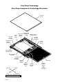
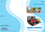
Easy Ramp Terminology
Easy Ramp Components Terminology Illustration
Top Panel
(Cover)
Left Chain
Tension
Assembly
Lower
Panel
(Pan)
Right Manual
Right Chain Release As- Electrical Harness
Tension
sembly
Energy Chain
Assembly
Carriage
Assembly
Drive Motor
Left Manual
Release
Assembly
Carriage
Track
Rollers
Manual Release
Cable Assembly
Ramp Cassette
(Housing)
Carriage
Assembly
Drive Motor
Manual
Release
Handle
Rear (In)
Left
Right
Front (Out)
As viewed from outside the vehicle
Page 2
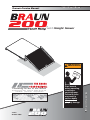
Hand Hold
Main
Elevation
(Rotation)
Axle
Carriage
Elevation
Motor
Standard
Platform
(Ramp)
and
Carriage
Assembly
Easy Ramp Terminology
Introduction
The Easy Ramp provides fully
automatic operation of all ramp
functions. Basic ramp operation
procedures are identical for all
Easy Ramp models. The operating instructions contained in this
manual address the operator input switches and the corresponding ramp functions. Instructions
are provided for manual operation
of the ramp in the event of power
or equipment failure.
Terminology: Become familiar
with the terminology that will be
used throughout this manual.
%HFRPHIDPLOLDUZLWKWKHLGHQWLÀcation of Easy Ramp components
and their functions. Contact your
ramp sales representative or call
The Braun Corporation at 1-800THE LIFT if any of this information is not fully understood.
Direction: The terms “left”,
“right”, “front” and “rear” will be
used throughout this manual to
indicate direction (as viewed from
the outside of the vehicle looking
directly at the ramp’s front cover).
Refer to the Ramp Terminology
,OOXVWUDWLRQVIRUFODULÀFDWLRQWR
direction terms.
Ramp Components
Refer to the Ramp Terminology
Illustrations on pages 2 and 3.
Control Box (Electronic Controller): The remote mounted
control box provides the logic
to manage the inputs in order
to produce the desired outputs
in terms of ramp function and
performance. In general terms of
abilities and features, the control
box is commonly referred to as
the “controller.”
Ramp Cassette (Housing):
The ramp cassette is the metal
structure (casing) mounted under
the vehicle which contains and
protects the platform and carriage
assemblies. The cassette contains all ramp components except
the control box when the ramp is
in the stowed position.
Carriage Assembly:
The carriage assembly consists of
the steel weldment that contains
the four track rollers, the main
rotation axle and the electric drive
motors. The carriage assembly
powers the platform assembly
in and out of the housing during
operation.
Platform Assembly:
The platform assembly consists of
WKHÁDWDOXPLQXPODPLQDWHXSRQ
which the wheelchair travels, the
stainless steel toe, the supporting
hinge, the associated skid pads,
and pressure mat.
Stow: Stow is the action of the
platform and carriage assembly
lowering to stow level, and fully
retracting when the STOW (IN)
switch is activated.
Stow Level: Stow level is the
height at which the platform and
carriage assembly extends and
retracts.
Floor Level: Floor level is the
height that the platform assembly
raises (elevates) to in order for
the wheelchair to enter or exit the
vehicle.
Retract: Retract is the action of
the platform and carriage assembly moving into the ramp cassette.
Obstruction Sensing: An
obstruction sensing feature is
standard with the Easy Ramp.
The controller monitors the
instantaneous current of all the
electric motors, and calculates
a ‘real time’ running average of
the current. It then compares
programmed peak (maximum vs.
instantaneous) and delta (instantaneous minus running average)
limits to determine if an obstruction has been encountered. The
programmed limits for the different models of the Easy Ramp
DUHVHOHFWHGZKLOHFRQÀJXULQJWKH
controller during ramp installation procedures (see Installation
Instructions for detailed information).
Obstruction Force: The obstruction force is maximum allowable
force (pounds or Newtons) that
the ramp exerts on a object durLQJDVSHFLÀFPRYHPHQW7KHUH
is a different force for each of the
four movements (extend, retract,
raise, lower). This force is a direct result of the obstruction sensing current limits, and is usually
VSHFLÀHGE\WKHFXVWRPHU
Deploy: Deploy is the action of
the platform and carriage assembly extending and raising (elevatLQJWRÁRRUOHYHOZKHQWKH'(PLOY (OUT) switch is activated.
Note: Further details regarding
ramp control switches and the
corresponding ramp functions are
provided in the Ramp Operating
Instructions below and on page 6.
Cable-activated Manual Release
System:
A cable-activated manual release
system disengages or “unlocks”
the carriage assembly drive chains
to allow the platform and carriage assemblies to be manually
moved out (extended) or moved in
(retracted), should it be necessary.
Complete details and manual
operating procedures are provided
on page 8.
Ramp Actions and Functions
Extend: Extend is the action of
the platform and carriage assembly moving out of the ramp cassette (housing).
Page 3
Ramp Operation Safety
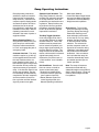
Safety Symbols
SAFETY FIRST!
Know That....
All information contained
in this manual and
supplements (if included), is provided for your safety. Familiarity
with proper operation instructions
as well as proper maintenance
procedures are necessary to ensure safe, troublefree operation.
Safety precautions are provided
to identify potentially hazardous
situations and provide instruction
on how to avoid them.
A
D
B
WARNING
C
This symbol indicates
important safety information regarding a
potentially hazardous
situation that could
result in serious
bodily injury and/or
property damage.
CAUTION
This symbol indicates
important information
regarding how to
avoid a hazardous
situation that could
result in minor personal injury or property damage.
Note:$GGLWLRQDOLQIRUPDWLRQSURYLGHGWRKHOSFODULI\RUGHWDLODVSHFLÀFVXEMHFW
These symbols will appear throughout this manual. Recognize the seriousness of this information.
Safety Precautions
WARNING Read this manual and supplement(s) before performing installation, operation or service
procedures.
Easy Ramp Operation Safety Precautions
WARNING Read manual and supplement(s) before operating ramp. Read and become familiar with
all safety precautions, pre-operation notes, operating instructions and manual operating
instructions before operating the ramp.
WARNING Inspect ramp before operation. Do not operate ramp if you suspect lift damage, wear or
any abnormal condition.
WARNING /RDGDQGXQORDGFOHDURIYHKLFXODUWUDIÀF
WARNING Load and unload on level surface only.
WARNING Engage vehicle parking brake before operating ramp.
WARNING Provide adequate clearance outside the vehicle to accommodate the ramp.
WARNING Keep operator and bystanders clear of area in which the ramp operates.
WARNING Do not overload or abuse. The load rating capacity is 300 kilograms (660 pounds).
WARNING 5DPSPXVWEHSRVLWLRQHGDWÁRRUOHYHOZKHQORDGLQJRUXQORDGLQJLQDQGRXWRIYHKLFOH
WARNING Do not activate control switches when anyone is near the area in which ramp operates.
WARNING Do not operate or board the ramp if you or your ramp attendant are intoxicated.
WARNING Wheelchair passengers must position and secure (buckle, engage, fasten, etc.) the wheelchair-equipped occupant seat belt before loading onto the ramp.
Page 4
Safety Precautions
WARNING Be aware of the ramp slope (angle).
WARNING Do not raise front wheelchair wheels (pull wheelie) when loading (boarding) the platform.
WARNING The wheelchair must be positioned in the center of the ramp when loading and unloading.
WARNING After manually releasing ramp, stow ramp and push manual release T-handle in fully and
move ramp in and out to engage ramp lock before driving vehicle. Failure to lock ramp may
result in unintended ramp deployment.
WARNING Keep owner’s manual in ramp-mounted vehicle at all times.
WARNING Never modify (alter) a Braun Corporation ramp.
WARNING Do not use accessory devices not authorized by The Braun Corporation.
WARNING Do not remove any guards or covers.
WARNING If the information contained in this manual is not fully understood, contact The Braun Corporation immediately.
WARNING Failure to follow these safety precautions may result in serious bodily injury and/or property
damage.
Installation and Service Safety Precautions
WARNING Read this manual, supplement(s) before performing installation, operation or service procedures.
WARNING Check for obstructions such as gas lines, wires, exhaust, etc. before drilling or cutting during installation procedures.
WARNING Route all cables clear of exhaust system, other hot areas, moving parts, wet areas, etc.
WARNING 5LVNRIHOHFWULFDOVKRFNRUÀUH8VHH[WUDFDUHZKHQPDNLQJHOHFWULFDOFRQQHFWLRQV&RQnect and secure as outlined in Installation Instructions and Wiring Diagrams.
WARNING 0DLQWHQDQFHDQGOXEULFDWLRQSURFHGXUHVPXVWEHSHUIRUPHGDVVSHFLÀHGLQWKLVPDQXDOE\
DXWKRUL]HGFHUWLÀHGVHUYLFHSHUVRQQHO
WARNING Disconnect the power cable at the battery prior to servicing.
WARNING Replacement parts must be Braun authorized replacements.
WARNING Never install screws or fasteners (other than factory equipped).
WARNING Failure to follow these safety precautions may result in serious bodily injury and/or property
damage.
Page 5
Installation Instructions
Parts List (28794K):
Easy Ramp WS Installation:
Braun Easy Ramp WS electronic controller
ER1150WS is exclusive for Weight Sensor
ramps. Install Weight Sensor Easy Ramp
models as outlined in this section.
Item Qty.
1
1
Description
Control Box - ER1300WS
Part No.
ER1150WS
Installation Procedures:
1. Mount ramp assembly using the six holes
shown in Photo C.
Mounting hardware
must be minimum 7/16"
or 12mm diameter.
Position the ramp, with
WRSFRYHUOLSÁXVKZLWK
vehicle door threshold.
Level the unit front-toback and side-to-side.
Mounting procedures
other than those speciÀHGKHUHmust be preapproved by a Braun
representative.
Ramp
Mounting
Holes
Photo C
2. Route free end of
ER1311WSA harness
WKURXJKYHKLFOHÁRRU
structure to desired
mounting location of control box.
Ramp
Mounting
Holes
D
Ramp
Connection
Page 6
Clamp
ER1311WSA
(to Control Box)
Installation Instructions
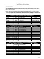
User Inputs/Outputs
7KHZHLJKWVHQVRUFRQWUROOHUKDVÀYHrequiredXVHULQSXWVDQGÀYHRSWLRQDOXVHURXWSXWV$WOHDVWIRXUXVHU
inputs are required to be connected in order for the ramp to function, whereas none of the user outputs
must be connected (optional).
Below is a list of the user inputs and outputs, including the designated connector pin number, wire color,
and description. 3OHDVHQRWHWKHRSWLRQDOXVHURXWSXWVKDYHPD[LPXPOLPLWDWLRQVDVVSHFLÀHGLQWKH
“Restrictions” column below.
Controller to Vehicle Connections (929.505-3 Amp Connector)
Function
Input
Input
Input
Input
Input
Input
Not Used
Not Used
Pin #
1
2
3
4
5
6
7
8
Wire Color
Black
Brown
Red
Orange
Yellow
Blue
Description
Park Brake Switch
Out Switch
In Switch
Reset Switch
+ 24 V Supply
Ground
Not Used
Not Used
Restrictions
Required
Required
Required
20 A Time Delay Fuse
Required
All Connections on this Connector Optional (929.505-6 Amp Connector)
Function
Input
Output
Output
Output
Output
Output
Output
Output
Output
Output
Output
Not Used
Not Used
Not Used
Not Used
Not Used
Not Used
Not Used
Pin #
1
2
3
4
5
6
7
8
9
10
11
12
13
14
15
16
17
18
Wire Color
Green
Purple
Grey
White
Black/White
Black
Red/White
Orange/Red
Yellow/White
Blue/White
Green/White
Not Used
Not Used
Not Used
Not Used
Not Used
Not Used
Not Used
Description
Indicater Power (+24V)
N.C. Ramp Full Deploy
N.O. Ramp Full Deploy
N.C. Ramp Full Stow
N.O. Ramp Full Stow
N.C. Ramp Malfunction
N.O. Ramp Malfunction
N.C. Ramp In Middle
N.O. Ramp In Middle
N.C. Manual Release Unlock
N.O. Manual Release Unlock
Restrictions
Ramp to Controller Connections (T1730-S14 Thomas & Betts Connector)
Function
Pin #
1
2
3
4
5
6
7
8
9
10
11
12
13
14
Wire Color
Yellow/ Red
Green/Black
Orange/Black
Orange
Green
Red/White
Yellow
Blue
Yellow
Violet
Not Used
Brown
Black/Red
Orange/Red
Description
Pressure Mat Return
Ramp + 24V
Ramp Ground
Ramp full out sensor
Ramp full in sensor
Drive motor +
Drive motor Ramp full up sensor
Ramp full down sensor
Ramp alarm
Not Used
Ramp manual release sensor
Elevate motor +
Elevate motor -
Restrictions
Page 7
Pre-Operation Notes
Operation Procedure Review:
The Easy Ramp operator should
review all safety precautions and
all operation procedures appearing in this manual prior to attempting to operate ramp. Failure to
do so may result in serious bodily
injury and/or property damage.
Operate the ramp through all
functions to ensure the proper
use and operation of the ramp is
clearly understood. Be sure to
review the manual operation procedures, particularly the proper
re-engagement procedure of the
manual cable release system
(see page 10). Any questions or
concerns should be forwarded to
your Braun representative.
Do not operate the ramp if it is
suspected to be damaged, have
Page 8
excessive wear, or any abnormal
condition. Discontinue use immediately and contact an authorized
Braun representative.
Preventative Maintenance:
Maintenance is necessary to
ensure safe and trouble-free
ramp operation. General preventative maintenance consisting of
inspecting, cleaning and lubricating procedures should be part
of a scheduled routine. Simple
inspections can detect potential ramp operational problems.
Adjustments can be made as
needed (details in Maintenance
and Adjustments section).
Regular preventative maintenance will reduce potential ramp
operation downtime and increase
the service life and reliability of
the ramp, as well as enhancing safety. Exposure to harsh
weather elements, environmental
conditions or heavy usage may
require more frequent maintenance and lubricating procedures.
See the Maintenance and Adjustments section for more detailed
information.
Cold Climate Recommendations: The vehicle in which the
ramp has been installed should
be stored in a garage or other
sheltered place if possible, especially during inclement weather
conditions. When the ramp is not
in use, it should be in the stowed
position to prohibit rain, snow, ice,
dirt, mud, or other foreign materials from entering the ramp opening or building up on the platform
surface.
Ramp Operating Instructions
Ramp Operating Instructions
address the required controller
inputs and the corresponding
ramp functions. Instructions for
FXVWRPHUVSHFLÀFGLVSOD\SDQHOV
and interlock options will not be
addressed due to the boundless variations in application and
installation of the ramp. Manual
Operating Instructions are addressed in the event of power or
equipment failure.
Before Operating Ramp: Always park the vehicle on a level
DUHDDZD\IURPYHKLFOHWUDIÀF
Place the vehicle transmission
in “Park” and engage the park or
emergency brake.
Customer Interlock: The ramp
controller requires a (+) 24V signal be supplied which interlocks
the ramp functions with a customer supplied vehicle signal. If
this interlock signal is not present,
the controller will not provide any
outputs necessary to operate the
ramp. If the interlock signal is lost
during ramp operation, the platform assembly will automatically
complete the ‘full stow’ sequence,
and the controller will not function any further until the interlock
signal is present once again.
Operator Input Switches: The
Easy Ramp electronic controller
provides fully automatic operation
of all ramp functions, which are
protected by the obstruction sensing feature. Ramp functions can
be performed from any position
the platform assembly happens
to be in at the time the operator
input switch is activated.
Two-Way Toggle Operation:
In two-way toggle mode, there
are separate switches for deploy
and stow functions. One of the
switches must be pressed and
held or locked into position (continuous input signal required) for
the Easy Ramp to operate. The
ramp will move in the selected direction until the switch is released
(signal interrupted), the unit
reaches the end of the travel, or
a “halt condition” occurs (details
follow).
Halt Conditions: Several conditions can cause a normal sequence to terminate (stop):
• Obstructions (details below)
• Customer Interlock signal lost
(see Customer Interlock)
• Manual Release System ‘unlocked’ signal present (see
Manual Operating Instructions:
Mechanical Method)
• Control Box Manual Input Switch
pressed (see Manual Operating
Instructions: Electrical Method)
• Weight sensed on platform
Obstructions: The controller
performs obstruction sensing
(see Easy Ramp Terminology:
Obstruction Sensing) on all
stow and deploy movements
of the ramp (in, out, up, down),
whether operated normally
or with the manual override
switches. The selected obstruction response mode conÀJXUHGLQWKHFRQWUROOHUGXULQJ
installation, immediately stops
the present movement when
obstructed. Once an obstruction has halted the ramp, the
controller automatically resets
and awaits operator input for
further operation.
Note: The ramp will sense an
obstruction and halt with any
substantial weight on the platform
(built in safety feature). Ramp will
continue when weight removed
from platform.
Page 9
Manual Operating Instructions
The Easy Ramp has the capability of being manually operated
(mechanical or electrical methods). If you experience power
or equipment failure, refer to the
step-by-step instructions to manually operate the ramp. Always
use extreme caution when operating the ramp manually. Read
all Manual Operating Instructions
carefully and thoroughly prior
to performing manual operating
procedures. Follow all Ramp
Operation Safety Precautions at
all times.
Mechanical Method
Cable-Activated Manual Release System: A cable activated
manual release system disengages (unlocks) the carriage assembly drive chains to allow the
platform assembly to be manually
extended or retracted as required.
A T-handle is provided on the
release cable for activation of the
manual release system (details
follow).
After manually extending or
retracting the platform assembly,
it is extremely important that the
cable-activated manual release
is positively reengaged to secure
(lock) the platform assembly
before loading a passenger or
continuing vehicle use (details
provided). Failure to reengage
and secure the platform may
result in unintended ramp
movement, which may result
in serious bodily injury and/or
property damage.
Manual Release System Security Sensor: A proximity sensor
detects when the cable-activated
manual release system is disengaged (unlocked) and provides a
ground (-) "unlocked" signal to the
controller. The unlocked signal
disables all controller functions so
that the mechanism can be manu-
Page 10
ally operated without the risk of
injury. The unlocked signal may
also be used to supply a visual
display to the operator that the
ramp is unlocked and must be
secured prior to any additional
operation of the ramp or vehicle.
Note: The unlocked sensor
LED is not supplied (customer
installed).
Self-Locking Release Pin: A
self-locking release pin allows the
platform assembly to be disconnected from the elevation mechanism, allowing a raised platform
to be manually lowered in the
event of a power failure. See
Photo on page 8. The release
pin should only be used when
the platform will not lower under
electric power, as stated in the
Electrical Method section (next).
To Manually Extend or Retract
Ramp:
1. Turn (loosen) the manual
release “T” handle 90°.
2. Pull the “T” handle fully outward (3" to 4").
3. Turn (tighten) the “T” handle
90° to secure handle in the
disengaged (unlocked) position.
Self-Locking Release Pin
4. Verify mechanism is disengaged (unlocked). View
customer installed sensor LED.
5. Carefully move the platform
in or out to desired location
using the platform Hand Hold.
Reengage Carriage Assembly
by Drive Chains:
1. Position the ramp platform
manually so that only 15 cm
is extended out of the cassette.
2. Turn (loosen) the manual
release “T” handle 90°.
3. Push the “T” handle fully
inward until handle contacts
shaft shoulder (3" to 4").
4. Grasp the platform Hand Hold
and move the platform slightly
outward until platform locks
into position (secured by
reengaging the carriage assembly with the drive chains).
Note: Do not push platform
inward to lock as it may then
create a binding condition in
the release mechanism and
will not release easily in the
future
5. Turn (tighten) the “T” handle
90° to secure handle in the
engaged (locked) position.
WARNING
Push T-handle in fully and manually move platform in and out to engage platform lock before driving vehicle. Failure to lock platform may result in unintended platform deployment. Unintended platform deployment may
result in serious bodily injury and/or property damage.
Manual Operating Instructions
6. Verify mechanism is reengaged (locked). View customer installed sensor LED,
or pull on the Hand Hold to
ensure no movement occurs.
7. Stow the remaining portion
of the platform by using the
electrical system.
To Manually Raise or Lower
Ramp:
1. Raise and hold platform assembly up to gain access to
the self-locking release pin.
2. Carefully remove release pin,
using caution as the platform
assembly may now move
freely (unhindered).
3. Manually raise or lower the
platform assembly as desired.
Note: The release pin will
only be able to be reinstalled
when the platform assembly
is returned to the original
position in which the pin was
removed.
Electrical Method
Control Box Manual Input
(Override) Switches: Manual
input switches are located inside
the electronic control box. Do
not use manual input switches
to operate the ramp when loading or unloading a passenger.
These momentary contact switches are provided as an override
for maintenance and service
purposes only. Manual input
switches should be activated by
TXDOLÀHGWHFKQLFLDQVRQO\
A service technician can use the
manual input (override) switches
to move the carriage assembly
to problem due to debris build
up, wear or mechanical binding
(obstruction sensing will not allow
ramp operation). The switches
can also be used in event of an
electrical problem remote from
the ramp electrical system (such
as a problem with a vehicle installed control switch or interlock
circuit).
Note: There must be power to
the ramp system (electronic controller) in order to use the manual
input (override) switches.
Each respective override switch
can be used to move the ramp
platform in the stated direction
(as labeled); OUT (extend), IN
(retract), UP (raise or elevate) or
DOWN (lower). The IN and OUT
switches use the control logic to
limit the travel to the maximums
as set by the respective sensor
pickups. Caution! The UP and
DOWN switches are not limited
to the sensor pickups, and thus
manual over travel can occur.
Over travel may result in damage
to ramp components or serious
bodily injury if not used with
extreme caution.
Note: A ramp operating under
normal conditions via an operator’s input switch will halt in the
event a manual input override
switch is pressed. Once released, the controller will automatically reset and function normally
when the next operator’s input
switch signal is received.
Page 11
Maintenance, Lubrication and Adjustments
A
B
Do not
spray
water
in this
DUHD
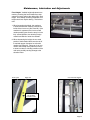
Overall View of Deployed Easy Ramp
Beeper
Note: In order to ensure proper and consistent
performance of the Braun Easy Ramp, routine maintenance in the form of cleaning, lubricating, inspecting, and adjusting is essential.
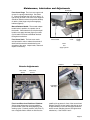
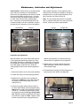
Exterior Maintenance
and Lubrication
Exterior
Maintenance
and Lubrication
The following items can be accessed after deploying
the platform, and without the removal of either the
top or bottom cover.
Cleaning/Lubrication: All exterior parts of the
ramp, accessible during stow or deploy, may be
cleaned with high pressure water, with exception
of being pointed directly into the cassette or at
the electrical connectors along the exterior frame.
A de-greasing agent and brush may be used if
necessary to remove large buildups. Do not spray
water directly into cassette or at the electrical
connectors and beeper area. Clean away debris
that may be built up in beeper that may reduce or
prohibit audibility.
Ramp Platform Hinge: Clean and lubricate the
ramp platform hinge. A light oil may be used on
the hinge, but should be limited to reduce the possible buildup of debris. See Photos C and D. Allow hinge to dry before applying lubricant (light oil).
C
D
Ramp
Platform
Hinge
Clean
and
Apply
Light Oil
Do not VSUD\ZDWHUGLUHFWO\LQWRFDVVHWWH
Page 12
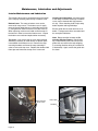
Electrical Connectors
Maintenance, Lubrication and Adjustments
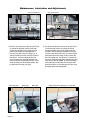
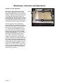
Front Seals
Front Cover Hinge: The front cover opens and
closes via a spring loaded hinge. See Photo
E. Clean and lubricate the front cover hinge. A
light oil may be used on the front cover hinge but
should be limited to reduce the possible buildup
of debris. Allow hinge to dry before applying
lubricant (light oil).
E
Manual Release Handle: The manual release
handle locks in position via a quarter turn of
the handle. Clean exterior then unlock and pull
handle out to apply lubricant (light oil) to shaft.
Cycle handle in and out to distribute lubricant
throughout mechanism.
Front Cover Seals: The front cover seals
are important in order to reduce the amount of
debris which enters the cassette during nonoperation of the ramp. Inspect seals, clean and
replace if necessary.
Manual Release Handle
Front
Cover
Clean
and
Apply Light Oil
Platform
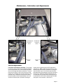
Exterior Adjustments
Stow Level
Sensor
Spring
Loaded
Hinge
Top Cover Lip
G
Floor Level
Sensor
F
Adjustable
Pick-Ups
Floor Level/Stow Level Position of Platform:
Vital to ramp performance is proper platform
position before, after and during deploying and
stowing cycles. Proximity sensors (see Photo F)
XVHDPDJQHWLFÀHOGWRVZLWFKRQDQGRIIDVWKH
metallic pick-up passes in front of the sensor head.
Distance from the sensor head to the pick-up must
be approximately 2 mm and should be checked to
ensure sensor switching (sensor LED lights when
switched on). See Photos H and I.
Page 13
Maintenance, Lubrication and Adjustments
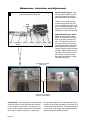
Floor Level Sensor
Stow Level Sensor
I
H
2 MM
2 MM
Set Screw
Floor Level Pick-Up
7KHÁRRUOHYHOXSVHQVRUSLFNXSVHH3KRWR
H) should be adjusted (via the set screw)
so that the elevation motor stops once the
platform has gently touched against the
top cover lip (see Photo G on page 17), or
vehicle threshold if further from the center of
the vehicle. Incorrect setting of this pickup could result in a large gap between the
platform and the threshold (too low) or in the
ramp retracting into the stowed position due
to obstruction sensing (too high).
Ramp Skid Pad
J
Page 14
Guide Rail
Slide Tube
Set Screw
Stow Level Pick-Up
2. The stow level (down) sensor pick-up (see Photo
I) should be set (via the set screw) to allow a
smooth transition of the ramp platform into the
cassette. Ramp skid pads, located on the back
corners of the ramp (see Photo J), reduce friction
at the point where the ramp corners contact the
top of the guide rail. See Photo K. Carefully observe the ramp skid pads when adjusting the stow
level sensor pick-up. Note: An incorrect setting
of the stow level could result in excessive wear,
premature failure, or the shearing off of the ramp
skid pads (pads are replaceable).
Ramp Skid Pad Contacting Top of Guide Rail
K
Maintenance, Lubrication and Adjustments
Floor Height: Variable height adjustments are
made by screwing the four threaded bar ramp
VXSSRUWVLQRXWWRDFKLHYHWKHGHVLUHGÁRRUOHYHO
height. Once initially set during installation, this
height should not require altering. Two items to
note.
1. When increasing the height, the maximum
is achieved when the ramp toe contacts the
inside of the front cover (see Photo M). If the
maximum is surpassed, the front cover will
remain partially open when the ramp is in the
fully stowed position, thus allowing foreign
material and debris to enter the cassette.
L
Lift ramp to access bolts.
2. When decreasing the height, the non-used
portion of the threaded studs must be cut off
to maintain proper clearance for main axle
rotation (see Photo N). Failure to do so may
result in the inability of the platform to lower
to stow level due to a binding condition of the
main axle, possibly causing damage to the
elevation motor.
Front Cover
Ramp Toe
M
Cut off excess threads.
N
Maximum Setting
Toe of Ramp
Contacts Cover
Page 15
Maintenance, Lubrication and Adjustments
Interior Maintenance and Lubrication
The following items can be accessed through the interior
of the ramp by removing either the top or bottom cover.
Bottom Cover: The snap-on bottom cover can be
removed for easy access. The bottom cover is easily
removed via two draw latches on each side (see Photo
P), along with four bolts across the front (see Photo O).
When replacing, make sure to install a new tie wrap on
the latches in order to secure the bottom cover. Inspect
the bottom cover seals and replace when necessary.
Top Cover: Only remove the top cover when deemed
DEVROXWHO\QHFHVVDU\WRREWDLQDFFHVVWRVSHFLÀFSDUWV
not available via the bottom cover. Remove the ramp
mounting hardware and lower the ramp assembly in
order to remove the top cover. Replace the double sided
foam tape seal whenever the top cover is removed.
Cleaning and Lubrication: All interior parts
of the ramp, accessible via the top or bottom
cover, may be cleaned with high pressure
air only. Use a cleansing cloth to wipe away
debris deposits and large buildups.
Ensure guide rails are clean and free of all
debris. Carriage track rollers are sealed and
do not require lubrication.
Note: Ramp controller includes an Obstruction Sensing Feature. Debris build
up or obstructions (rocks, sand, dirt) in the
guide rails can result in the ramp stopping
or reversing direction during in-out functions
(if obstructed). Again, ensure the guide rails
are clean.
O
P
Bolts Securing
Front Cover
Draw Latch
Tie Wrap
Page 16
Maintenance, Lubrication and Adjustments
Q
Overall View
R
Full Out/Deployed
Positional
Sensor
Pick-Up
Plate
Full In/Stowed
Positional
Sensor
S
Pick-Up
Plate
Interior Adjustments
Full In/Full Out Position of Carriage: The carriage
houses two sensors that provide positional feedback
of full out (see Photo R) or full in/stowed (see Photo
S) for the carriage and platform assembly. The proximity sensors switch on and off as the sensor head
passes over a metallic pick-up plate mounted on the
cassette frame. Distance from the sensor head to
the pick-up plate must be approximately 4 mm and
should be checked (due to possible loosening) to
ensure sensor switching (sensor LED lights when
switched on). Note: Verify the full out sensor is distanced properly to remain lit (switched on) during the
entire elevation cycle. If the sensor light should be
intermittent during the elevation cycle, then reposition
the sensor to reduce the distance between the senVRUKHDGDQGSLFNXSSODWHZKLOHFRQÀUPLQJWKHUHLV
no interference of the sensor head and pick-up plate
during the in/out movement. See Photo R.
Page 17
Maintenance, Lubrication and Adjustments
T
Manual Release System: If the
UHOHDVHFDEOHLVGLIÀFXOWWRSXOOWR
unlock the system, inspect the
guide and slider shown in Photo T.
Manual Release
(dotted lines represent deployment)
&RQÀUPQRGLUWPHWDOVKDYLQJV
or other foreign debris are present and restricting the slider. Also,
check compression spring to verify
the open end of the spring is not
binding the movement of the slider.
4 MM
Cable
Compression
Spring
Sensor
Pick-Up
Stop Pin
Slider
.
Axle
Manual Release Sensor Adjustment: Inspect manual release
VHQVRUWRFRQÀUP/('LVOLWZKHQ
slider is precisely released from
axle. The distance from the sensor head to the pick-up must be
approximately 4mm or less at this
precise point to ensure Manual
Release Locked/Unlocked signal is
accurate. Adjust distance by moving sensor in/out via the sensor’s
two locknuts. Operate several
WLPHVDIWHUDGMXVWPHQWWRFRQÀUP
new setting is correct.
Connecting or “Timing”
Rear Chain
U
V
Left Drive Chain
Right Drive Chain
Light Oil can be applied
to chains (small amount)
Chain System: The ramp utilizes a 3 chain system.
Two drive chains, left and right, provide the means
for the carriage to travel along. The third chain, in
the rear of the cassette, interlocks the left and right
drive chain to rotate in sequence (or equal time).
Page 18
During normal operation, none of the 3 chains move.
However, during manual operation of the ramp, all 3
chains travel equal distances. To lubricate, a light oil
may be used on the chains, but should be limited to
reduce the possible buildup of debris.
Maintenance, Lubrication and Adjustments
Chain Tension: Equal tension on the left and right
drive chains is necessary to reduce binding effects on the carriage bearings and allow for smooth
movement throughout the in/out cycle. An excessively loose chain may enable the drive sprocket
to “jump” teeth, thus providing a binding situation. Conversely, an excessively tight chain may
increase the drag on the drive sprockets, and thus
increase the force necessary to move the platform
Threaded Rod
Locknuts
during manual operation. Each respective side’s
FKDLQWHQVLRQFDQHDVLO\EHPRGLÀHGE\PRYLQJWKH
threaded rod in or out to the desired position via a
pair of locknuts (see Photos W and X).
Note: The rear timing chain tension is not adjustable. If problems arise due to the rear timing chain
tension, contact your Braun representative.
Locknuts
Threaded Rod
W
X
Drive Chain
Drive Chain
Inspection and Adjustment:
%UDXQVSHFLÀHVDGULYHFKDLQWHQVLRQWKDWUHTXLUHV
a force gauge and metric tape measure for accurate setting, inspecting, or adjusting on all models
of Easy Ramps. Braun recommends the Wagner
Force Dial gauge model FDK 20 or FDN 100.
These gauges can be found at www.wagnerforce.
com.
1. Remove the bottom cover of the ramp assembly.
GLIÀFXOWUDPSRSHUDWLRQRUH[FHVVLYHZHDUSUHmature failure of respective drive components.
5. Repeat steps 3-4 for the opposite drive chain,
again ensuring the tension force is within the
recommended range.
6. Proceed with the Carriage "Full Out" Alignment to
ensure proper chain tension and alignment.
2. Position the ramp in the fully deployed position.
Y
3. Measuring from the back of the carriage the
distance L1 = 200mm (for all models), hook the
force gauge to the outside edge of the drive
chain (photo Y).
4. Pull the force gauge inward until the center of
the drive chain linkage measures approximately
85mm from the edge of the extruded housing (L2
in photo Y). The nominal chain tension (on the
force gauge) should read 5.5 kg ± 0.5 kg (55N ±
5N). Adjust the tension by tightening the respective locknuts as required. Note: Improper chain
tension may result in poor ramp performance,
L1
L2 = 85mm
Page 19
Maintenance, Lubrication and Adjustments
Carriage “Full Out” Alignment:
When the carriage is deployed to the “Full
Out” position, the front bar of the carriage
should align parallel with the union bar of the
housing. This alignment will help ensure that
a fully deployed and elevated platform will
properly align with the bus threshold. Properly maintaining this carriage alignment will also
help provide optimal performance during the
in/out movement of the carriage and platform.
Accurate inspection of the carriage alignment can be done by measuring the distance
behind each drive motor from the rear carriage
bar to the rear housing (L3 and L4 in Photo
Z). Comparing the two distances, increase
the chain tension on the side of the longest
distance, via the tension locknut, 1/2 turn
for each 1mm difference. Cycle the ramp
several times, observing the full out alignment of the ramp with the bus threshold.
Stopping once again at the fully deployed
position re-measure the distance behind each
drive motor from the rear carriage bar to the
rear housing and adjust the chain tension accordingly until the full out alignment from side
to side is within ±1mm. Note: If the chain
tension of one side is overly increased, it may
result in a binding condition of the track rollers in the guide rail and lead to obstructions
sensed by the control box.
Page 20
Z
L3
Locknuts
L4
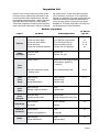
Inspection List
Below is a list of routine inspections which should
be done to ensure optimal ramp performance and
prevent excessive wear leading to poor operation
and possible component failure. Refer to the speciÀHGSDJHVZLWKLQWKLVPDQXDOIRUIXUWKHUGHWDLOV
These ramp inspections should be performed if the
ramp has unusual malfunctions, the bus is undergo-
ing routine service, or after every 500 completed
F\FOHVZKLFKHYHUFRPHVÀUVW,IWKHUDPSIDLOVWR
operate at a satisfactory level after performing these
inspections and the accompanying adjustment or
course of action, please contact your local Braun
distributor or The Braun Corporation’s Product Support Department for further assistance.
Exterior Inspections
Inspect
For What
Action/Adjustment
See Manual
Page No.
Torn or detached tape
3URSHUÁRRUOHYHOKHLJKW
3URSHUÁRRUOHYHOURWDWLRQ
Proper stow level
3URSHUÁRRUWKUHVKROGDOLJQPHQW
Replace tape
Floor height per ramp support
Floor level sensor pick-up
Stow level sensor pick-up
Carriage “full out” alignment
Excessive wear
Loose rivet
Replace pad
Replace rivet, pad
Proper closure
Inspect front cover hinge (next item)
Check platform position for
clearance.
Excessive interference during
stowing cycles
See Troubleshooting Guide
30, 31
Front
Cover
Hinge
Debris buildup
Pin fatigue
Spring fatigue/failure
Clean, lubricate
Replace hinge
Replace hinge
16, 17
Front
Cover
Seals
Debris build up
Damage, fatigue & adhesion
Clean
Replace seals
Excessive wear
Uncharacteristic marks
Replace pads
Identify marking item and correct
Ramp Hinge
Debris buildup
Pin fatigue
Clean, lubricate
Replace
16
Electrical
Connectors
Debris buildup
Positive lock engagement
Clean
Re-engage
16
Debris buildup
Proper audible level
Clean
Replace beeper
16
Platform
Ramp
Skid Pads
Front
Cover
Front
Cover
Skid pads
Beeper
19
17, 18
17, 18
24
Page 21
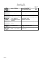
Inspection List
Exterior Inspection
Inspect
For What
Action/Adjustment
See Manual
Page No.
Manual
Release
Cable
Smooth, easy operation
Clean, lubricate cable
See Troubleshooting Guide
Manual
Release
Sensor
Debris buildup
Cut or damaged lead wire
Clean
Repair or replace sensor
16
Bottom
Cover
Damage resulting in ramp
interference
Replace bottom cover
20
Secured with tie-wrap
Proper compression of bottom
cover seal
Add tie-wrap if missing
Adjust latch “draw” hook
Top Cover
Debris buildup
Damage resulting in ramp interference
Clean
Replace top cover
Top Cover
Seal
Proper adhesion/seal
Replace double-faced adhesive
tape
Easy Ramp
Label
Damage or lack of adhesion
Replace label
Bottom Cover
Latches
Page 22
22
30, 31
Inspection List
Interior Inspections (with snap-on bottom cover removed)
Inspect
For What
Action/Adjustment
See Manual
Page No.
Proper alignment
Carriage “full out” alignment
24
Extruded
Guide Rails
Debris buildup
Clean
20
Chain
Debris buildup
Loose chain
Clean, lubricate
Chain tension
22
23
Manual
Release
Assembly
Debris buildup
Restricted movement
Proper sensor switching
22
Electrical
Wiring
Cut/worn wire/jacket
Corroded terminal
Clean, lubricate
See Troubleshooting Guide (back
page)
Reset sensor position
Repair or replace
Clean or replace
Full In/Out
Sensor
Pick-ups
Debris buildup
Clean
21
Debris buildup
Damage, fatigue and lack of
adhesion
Clean
Replace seals
Fully
Deployed
Carriage
Bottom Cover
Seals
22
Page 23
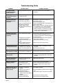
Troubleshooting Guide
Problem
Possible Cause
Possible Solution
Carriage and ramp
misalignment during
In/Out movement
Designed allowable tolerances
No action required unless other problems
observed.
Deployed platform
misalignment with bus
threshold
Chain tension or position with
carriage sprockets
Inspect/check carriage “full out alignment”
Repeating obstruction
sensed during in/out
movement
Misalignment of carriage
Differential in chain tension
Inspect/check carriage “full out alignment”
Inspect drive chains
Inspect extruded guide rails
Check for identifying marks on all skid pads, etc.
Check supply voltage
Place controller in ‘service’ mode and cycle ramp.
If no obstructions occur, return controller to
‘operating’ mode and clean and lubricate
platform assembly. If obstructions do occur in
‘service’ mode, discontinue use and contact
authorized Braun representative.
Debris on extruded guide rails
Mechanical interferences
Low/high supply voltage
Exceeded current draw limits of
control box
Repeating obstruction
sensed during up/down
movement
Loss of full out sensor signal
Threaded bar ramp supports
interfere with carriage
3ODWIRUPFRQWDFWLQJÁRRUOHYHO
edge
Platform contacting union bar
during inward movement
Inspect sensor LED during up/down movement. If
LED is intermittent, reposition sensor as
required to ensure sensor remains lit during up/
down movement.
Cut off excess threaded bar ramp supports to
allow proper clearance
5HSRVLWLRQÁRRUOHYHOVHQVRUSLFNXS
Reposition stow level sensor pick-up
Grinding/rubbing sound
during in/out movement
Threaded bar ramp support
rubbing on front cover skid pad
Debris on extruded guide rails
Grind leading edges of threaded bar if noise
intolerable
Inspect extruded guide rails
Front cover remains open
when platform is stowed
Hinge springs fractured
Carriage/platform misalignment
Replace hinge
Inspect/check carriage “full out” alignment
Manual release cable
pulls too hard
Slider binding in guide
Remove slider. Check for foreign debris, metal
shavings, or spring interference. Clean and
lubricate.
Manually released platform pulls too hard
Left/right drive chain tension
excessively high
Adjust drive chain tension.
Manual release will not
reengage properly
Spring failed/has interference
Slider binding in guide
Manual release giving false
signal
Inspect spring and correct as needed
Inspect, clean and lubricate slider and guide
Inspect and adjust manual release sensor
position
Ramp/controller will not
respond or function to
inputs properly
&RQWUROOHUQRWFRQÀJXUHG
properly
Jumpers loose or fallen off
controller terminals
Interlocks not installed/connected correctly (Park, Manual
Release)
Controller relay failure
Electrical harness failure
5HFRQÀJXUHFRQWUROOHU
Page 24
,QVSHFWDQGUHSODFHMXPSHUVLQSURSHUFRQÀJXUD
tion
Verify interlock signals are present as required
Inspect relays and replace if failed
Inspect harness and replace if failed
Troubleshooting Guide
Problem
Panel binds on front
cover during stowing
sequence
Possible Cause
Front cover edge is hitting the
screws/nuts of the platform hinge
assembly
Possible Solution
Adjust stow height lower
Grind clearance for nuts
Page 25
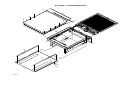
Easy Ramp Overall Exploded View Parts List
Item
Qty.
1
2
3
4
5
6
7
8
9
10
11
12
13
14
15
16
17
18
19
20
1
1
1
10
12'
1
4
4
1
1
1
3
1
1
1
10
4
10'
1
1
Page 26
Description
Carriage and Ramp Assembly
Frame Assembly
Panel, Upper
Screw, M5 x 20, Hex Head Cap
Tape 1/16" x 3/4" Double Face
Panel Assembly, Lower
Washer, M6 Fender
Screw, M6 x 16MM, Hex, Cap
Chain, Roller, 8MM Pitch
Chain, Roller, 8MM Pitch
Chain, Roller, 8MM Pitch
Master Link, 8MM Pitch
Sponge Strip, 1/2" x 1/4" x 40"
Decal, Logo, Cover, Easy Ramp
Decal, Upper Panel, Easy Ramp
Nut, M5 Nylock
Washer, M6 Lock
Tape, Cap, 1 1/2"
Control Box, Main Ramp (Not Shown)
Harness, Main (Not Shown)
Easy Ramp
ER1300WS
See Pages 4-7
See Page 7
R1265-1300
27452
82033R
ER1369A-13005
27759
28785
27429R101.00
27429R98.4375
27429R63.625
27428
82062R040
28223
28224
83038
28787
10416R
ER1150WS
ER1315WSA-1300
Easy Ramp WS Overall Exploded View
15
1
4
3
13
4
5
2
9
12
11
12
10
16
16
14
12
18
18
7
17
8
6
Page 27
Page 27
U
ve
ra Ea nfo
ll sy ld
Ex R f
pl am or:
od p
ed
V
ie
w
ER1300WS Carriage and Ramp Assembly Exploded View
O
55
55
55
57
1
55
55
55
54
31
18
2
10
13
11
14
57
3
11
4
43
2
55
52
55
55
16
38
36 40
22
37
7
55
19
35
55
9
17
16
53
8
54
12 18
33
55
55
16
55
21
39
16
20
47
41
48
24
49
45
50
52
25
42
53
6
26
43
45
46
23
47
48
29
30
45
56
49
44
28
27
50
15
Note: Typical Both Ends
56
5
51
32
Page 28
34
Page 28
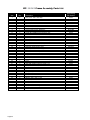
ER1300WS Carriage and Ramp Assembly Parts List
Item
Qty.
Description
1
2
3
4
5
6
7
8
9
10
11
12
13
14
15
16
17
18
19
20
21
22
23
24
25
26
27
28
29
30
31
32
33
34
35
36
37
38
39
40
41
42
43
44
45
46
47
48
49
50
51
52
53
54
55
56
57
1
12
11
1
4
4
2
1
2
2
2
1
4
1
4
8
1
2
1
1
1
1
1
8
2
1
2
1
1
4-8
1
8
1
4
1
1
2
1
2
2
4
2
2
2
9
1
2
2
2
2
1
1
4
2
16
4
2
Ramp Sub Assembly
Screw, M4 x 16, Flat Socket Head, Cap - SS
Locknut, M4, Nylon Insert
Support Weldment, Adjustable Ramp, Carriage
Pin Weldment, Bearing, Carriage
Bearing, UHMW, 1 1/2", Flat
Screw, M5 x 10 Hex, Cap
Tag, Serial No. / Series No.
Rivet, Pop, 3/16"
Guide, Elevation, Main Axle
Screw, M6 x 8, Cup Point, Socket, Set
Bracket, Support, Main Axle
Screw, M6 x 12, Flat Socket Head Cap
Bearing, Plain Plastic, 1" I.D. X 1 1/4" O.D.
Screw, M6 x 16, Hex
Locknut, M12, Nylon Insert
Axle Weldment, Main Elevation, Carriage
Motor, Drive Assembly, Carriage
Screw, M8 x 100, Hex, Cap
Pin, 5/16" O.D. X 2" Grip, Self Locking
Spacer, Elevation, Carriage
Screw, M8 x 20, Socket Low Head, Cap
Pin, Clevis, 5/16" O.D. X 12-3/64" Grip
Bearing, Plain Plastic, 8MM I.D. X 10MM O.D.
Link, Elevation, Carriage
Yoke, Elevation, Carriage
Joint, Ball Rod End, Elevation Linkage
Spacer, Ball Joint, Carriage
Stud, M8 x 50, Threaded
Washer, .328" x .562" x .042" (Qty. varies)
Motor, Elevation Assembly, Carriage
E-Clip, 7/16" Shaft, 11/32" Groove
Holder, Cable Tie, 2 Way
Roller, Track, 38MM OD x 12MM ID
Screw, M6 x 16, Button, Socket Head, Cap
Washer, M6, Fender
Bearing, Ball, Elevation
Screw, M8 x 35, Hex, Cap
Bearing, Ball, Top Panel Support
Washer, M8, Flat
Locknut, M8, Nylon Insert
Bearing, Plain Plastic, 16mm ID x 18mm OD
Screw, M10 x 16, Socket Head, Cap
Plug, End Cap, 1.5" Square Tube
Screw, M6 x 10, Flat Head Socket, Cap
Carriage Drive Weldment
Bearing, Plastic Disc, 10mm ID x 18mm OD
Sprocket, Drive Position, Carriage
Bearing, Plain Plastic, 10mm ID x 12mm OD
Axle, M8, Sprocket, Carriage
Gear, Elevation Reduction, Carriage
Harness, Electrical, Ramp
Sensor, 24V, M12 x 42, Proximity
Pad, Skid, Ramp, Top
Rivet, Pop, M4 x 10, Countersunk Blind
Washer, M6 Lock
Pad, Alignment Skid
Easy Ramp
ER1300WS
ER1405A-WS1300
33278
83037
ER1035W
ER1179W
PS1006
27449
18548M
11512
ER1086
27460
ER1087
27458
27777
28785
22876
ER1030W
ER1121A
27465
27840
ER1082
27762
27841
27497
ER1084
ER1083
27494
ER1081
27485
83583
ER1122A
27796
27510
27788
82691
27759
27495
27468
27496
27462
83042
27500
27434-SS
27843
27722
ER1225W
27502
27490
27498
ER1085
27487
ER1312A-WS1300
32323
ER1239
27441
28787
ER1263
Page 29
ER1300WS Frame Assembly Parts List
Item
Qty.
1
2
3
4
5
6
7
8
9
10
11
12
13
14
15
16
17
18
19
20
21
22
23
24
25
26
27
28
29
30
31
32
33
34
35
36
37
38
39
40
41
42
43
44
45
46
47
8
1
1
2
2
2
1
8
1
22
2
8
1
1
1
11
1
1
1
1
1
25
1
3
7
8
8
6
4
1
2
1
1
2
1
2
2
1
2
2
3
1
1
5
1
1
8
Page 30
Description
Rivet, 5/32" .188" x .250" Grip
Plate, Skid, Frame, Right
Plate, Skid, Frame, Left
Ring, 5/16", External Snap
Sprocket, Fixed Guide, Manual Release
Bearing, Plain Plastic, 8MM I.D. X 10MM O.D.
Cover, Front, Cassette
Screw, M4 X 10MM, Hex Head, Cap
Union, Exterior Frame, Weldment
Rivet, Pop, SD64BS 3/16" x 13/.25
Screw, M5 X 45MM, Flat Socket Head, Cap
Screw, M8 X 25MM, Flat Socket Head, Cap
Slide, Manual Release
Assembly, Manual Release, Left
Assembly, Chain Tension, Left
Screw, M5 X 20MM, Flat Socket Head, Cap
Screw, M6 X 16MM, Flat Socket Head, Cap
Harness, Sensor and Alarm, Ramp
Locknut, M6, Nylon Insert
Assembly, Chain Tension, Right
Assembly, Manual Release, Right
Locknut, M5, Nylon Insert
Harness, Electrical, Ramp
Strap, M12, Rubber Cushioned, Steel, Loop
Strap, M6, Rubber Cushioned, Steel. Loop
Locknut, M8, Nylon Insert
Washer, M8, Fender
Screw, M5 x 10MM, Flat Socket Head, Cap
Latch
Spring, Compression
Strap, M8, Rubber Cushioned, Steel, Loop
Cable, Manual Release, M8 x 1250MM x 79MM
Bracket,Manual Release
Spacer, Manual Release
Frame, Weldment, Exterior, Aluminum
Sponge Strip, 1/2" x 1/4" x 4"
Screw, M5 x 20MM, Hex Head, Cap
Cover, Plate, Manual Release Slide
Tape, Cap, 1.5" x 2.0"
Washer, .328" x .562" x .042"
Plate, Skid, Front Cover
Hinge, Cover, 1.5" x 41.5"
Wire, Cover, UHMW
Rivet, Pop, SD66BS, 3/16" x .25/.38
Plate, Skid Pad - SP Finger
Plate, Skid Pad - SP Finger
Rivet, M4 x 10 Countersink Blind
Easy Ramp
ER1300WS
28583
ER1292
ER1293
24570
27491
27497
ER1370
27706
ER1210W
11513
27454
27466
ER1245W
ER1041A
ER1056A
27451
27758
ER1315WSA-1300
83039
ER1061A
ER1051A
83038
ER1312A-WS1300
27435
27456
83042
27738
27448
ER1301
27478
27464
27427
ER1094
ER1093
ER1205W-1500
82062R004.00
27452
ER1251
1416R002.00
83583
ER1072
27425
ER1241
14993
ER1264
ER1267
2744
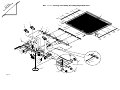
ER1300WS Frame Assembly Exploded View
10
41
10
44
2
41
44
4
40
5
44
44
6
10
43
22
3
24
22
22
24
29
1
12
22
36
21
23
28
20
24
22
22
25
8
22 25
47
12
18
22
25 22
16
11
37
16
16
Note: Cover Assembly
ER1375A includes items 7, 41,
42 and applicable fasteners.
36
11
15
16
45
39
42
19
29
25
22
13
47
28
46
16
22
34
33
38
29
27
27
7
9
1
22
17
26
27
26
22
35
16
25
26
34
16
16
1
22
32
22
16
25 22
22
27
29
22
26
22
1
31
27
22
26
22
26
27
22 25
39
31
18
22
30
22
Page 31
Page 31
U
ve
ra Ea nfo
ll sy ld
Ex R f
pl am or:
od p
ed
V
ie
w
ER1300WS Easy Ramp Subassemblies Exploded View
17
17
19
ER1051A
O
16
7
15
7
5
ER1061A
10
8
11
7
12
18
18
14
9
ER1056A
12
13
8
11
12
ER1041A
12
3
10
1
9
4
5
2
6
7
6
Page 32
Page 32
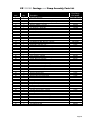
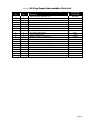
Series 04 Easy Ramp Subassemblies Parts List
Item
Qty.
1
2
3
4
5
6
7
8
9
10
11
12
13
14
15
16
17
18
19
1
1
1
1
2
2
4
2
2
2
2
4
1
1
1
1
2
2
1
Description
Manual Release, Weldment, Left
Screw, M5 x 10MM, Hex Head, Cap
Shaft, Left, Manual Release
Bearing, Plain Plastic, 15MM I.D. X 17MM O.D.
Sprocket, Double, Manual Release
Pin, M2.5 x 20MM, Steel Roll, Plain
Bearing, Plain Plastic, 8MM I.D. X 10MM O.D.
Roller, Chain Tension
Pin, Clevis, Chain Tension
Clevis, Chain Tensioner
Adjustor, Threaded, Chain Tension
Locknut, M12, Nylon Insert
Chain Tension, Weldment, Left
Chain Tension, Weldment, Right
Manual Release, Weldment, Right
Sprocket, Fixed Guide, Manual Release
Screw, M6 x 8MM, Cup Point Socket, Set
Shaft, Right, Manual Release
Tubing, .5 O.D. x .334 I.D. x 1.06"
Easy Ramp
ER1300WS
ER1040W
27449
ER1037
27499
27488
27436
27497
ER1252
27511
27513
ER1090
22876
ER1055W
ER1060W
ER1050W
27491
27460
ER1047
15865R001.06
Page 33
Blank for Layout Purposes
Page 34
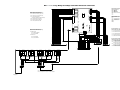
ER1300WS Easy Ramp Caradap Controller Electical Schematic
J2
J6
GN 1
1
OUTPUT RELAYS - OPERATOR DISPLAY
(LEDS LIT WHEN RELAY ACTIVE)
2
GY 3
3
W4
4
BK/W 5
5
BK/R 6
6
R/W 7
7
OR/R 8
8
Y/W 9
9
10
LD17
K2
LD18
K3
LD19
LD20
K5
LD21
J7
LD3
4
W/R
LD4
5
GN/R
LD5
6
Y/R
LD6
7
9
10
1
3
BK 1
4
BN 2
LD12
5
RED 3
5
LD13
6
LD14
7
LD22
U15
6
7
8
LD9
LD10 PARK BRAKE ON
LD11 OUT SWITCH ON
LD12 IN SWITCH ON
LD13
LD14
LD15
LD16
9
LD16
9
OPERATOR INPUT SWITCHES
(LEDS LIT WHEN ON)
8
LD15
10
10
11
11
12
12
RAMP OUT
RAMP IN
RAMP UP
RAMP DOWN
MANUAL RELEASE UNLOCKED
J3
4
3
K6
LD1
LD2
LD3
LD4
LD5
LD6
LD7
LD8
8
LD8
2
GN/W 11
LD22 RAMP OPERATING ALARM
PR/W
LD11
2
LD21 MANUAL RELEASE UNLOCK
3
LD10
BU/W 10
R/BK VT
LD20 RAMP IN MIDDLE POSITION
2
LD2
LD9
1
LD19 RAMP MALFUNCTION
(VOID WITH OPERATOR RESET SWITCH)
W/GN
LD1
LD7
K4
LD17 RAMP FULL DEPLOY (OUT & UP)
LD18 RAMP FULL STOW (DOWN & IN)
RAMP FEEDBACK SENSORS (RFS)
(LEDS LIT WHEN ON)
1
K1
MICROPROCESSOR
PR 2
OR 4
LD32
POT 1
O
R
POT 2
S5
K9
POT 3
LD28
J4
INPUT RELAYS - RAMP MOTORS
(LEDS LIT WHEN RELAY ACTIVE (+24v))
B
L
K
B
L
K
B
L
K
B
L
K
1
2
3
4
G
N
B
U
Y
L
B
N
S1
S2
POT 4
K10
LD27
1
S3
2
B
L
K
B
L
K
B
L
K
B
L
K
5
6
7
8
ELEVATE MOTOR
P4
3
K11
LD30
4
B
L
K
B
L
K
B
L
K
9
1
0
1
1
J1
LD29
V
T
TECHNICIAN MANUAL OVERRIDE SWITCHES
(MUST BE USED IN COMBINATION WITH S5)
S4
K12
S1 OUT OVERRIDE SWITCH
1 2 3 4
SERIAL NO.
XXXXXXXXX
LD28 DOWN MOVEMENT
OR/BK
B
K
B
K
B
K
B
K
1
2
3
4
S2 IN OVERRIDE SWITCH
S3 UP OVERRIDE SWITCH
GN/BK
LD27 UP MOVEMENT
Y
S4 DOWN OVERRIDE SWITCH
BU
DRIVE MOTOR
B
K
OR
B
U
GN
LD30 IN MOVEMENT
5
BU
S5 COMMON OVERRIDE SWITCH
YL
LD29 OUT MOVEMENT
+
2
4
V
O
L
T
S
I
N
P
U
T
N
C
N
O
N
C
N
O
N
C
N
O
N
C
N
O
N
C
N
O
R
A
M
P
R
A
M
P
R
A
M
P
R
A
M
P
R
A
M
P
R
A
M
P
R
A
M
P
R
A
M
P
M
A
N
M
A
N
R
E
L
U
N
L
O
C
K
BN
P
A
R
K
OR/R
F
U
L
L
D
E
P
L
O
Y
F
U
L
L
D
E
P
L
O
Y
F
U
L
L
S
T
O
W
F
U
L
L
S
T
O
W
M
A
L
F
U
N
C
T
I
O
N
M
A
L
F
U
N
C
T
I
O
N
I
N
I
N
R
E
L
M
I
D
D
L
E
M
I
D
D
L
E
U
N
L
O
C
K
Y
B
R
A
K
E
R/W
VT
P
R
E
S
S
U
R
E
M
A
T
T
CN3
1 2 3 4 5 6 7 8 9 10 11 12 13 14 15 16 17 18
AMP CONNECTOR
929.505-6
R
E
T
U
R
N
OUTPUT SIGNALS 2-11
R
A
M
P
+
2
4
V
O
L
T
S
R
A
M
P
G
R
O
U
N
D
R
F
S
R
F
S
O
U
T
I
N
D
R
I
V
E
D
R
I
V
E
M
O
T
O
R
M
O
T
O
R
+
P
O
S
N
E
G
R
F
S
R
F
S
U
P
D
O
W
N
R
A
M
P
A
L
A
R
M
+
2
4
V
R
F
S
M
A
N
R
E
L
U
N
L
O
C
K
E
L
E
V
A
T
E
E
L
E
V
A
T
E
M
O
T
O
R
M
O
T
O
R
+
P
O
S
N
E
G
Y
P5
B
K
/
R
B
U
Y
/
R
S
W
I
T
C
H
1 2 3 4 5 6 7 8 9
AMP CONNECTOR
26600
PINS 151224
O
U
T
S
W
I
T
C
H
I
N
S
W
I
T
C
H
R
E
S
E
T
S
W
I
T
C
H
S
U
P
P
L
Y
S
U
P
P
L
Y
+
2
4
-
V
O
L
T
S
G
R
O
U
N
D
CN2
1 2 3 4 5 6 7 8
AMP CONNECTOR
929.505-3
INPUT SIGNALS (24V WHEN ACTIVE)
J5
TECHNICIAN RAMP SENSITIVITY ADJUSTMENTS
(VARIES MOTOR MAX AND MIN CURRENT LIMITATIONS)
POT 1 LIMITS AVERAGE CURRENT DRAW OF MOTOR
DURING UP MOVEMENT
POT 2 LIMITS PEAK CURRENT DRAW OF MOTOR
DURING UP/DOWN MOVEMENT
POT 3 LIMITS AVERAGE CURRENT DRAW OF MOTOR
DURING OUT MOVEMENT
POT 4 LIMITS PEAK CURRENT DRAW OF MOTOR
DURING IN/OUT MOVEMENT
CN1
1 2 3 4 5 6 7 8 9 10 11 12 13 14
THOMAS & BETTS CONNECTOR
T1730-S14
RAMP SIGNALS
87A
86
87
30
VF4-15F11-S01
85
K5
87A
85
86
VF4-15F11
87
K4
30
87
86
85
30
VF4-15F11
87A
K3
87A
86
87
VF4-15F11
85
30
86
87
85
K2
87A
VF4-15F11
30
K1
GN/W
BU
B
U
/
B
K
P4
B
U
/
R
1
2
R
/
G
N
W
/
B
K
3
4
AMP 770827-1
SOCKET 60619-1
O
R
/ Y
R /
R
J5
9
8
B
U
Y
B
/
W K
/
R
7
6
5
4
R
/
W
3
GN/W
Y
2
1
26601 WITH SOCKET 15125
PIN 1 = 24V CONSTANT
PIN 8 = PRESSURE MAT GROUND WHEN PRESSED.
Page 35
Page 35
U
ve
ra Ea nfo
ll sy ld
Ex R f
pl am or:
od p
ed
V
ie
w
O
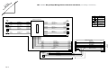
ER1300WS Easy Ramp Wiring Harness Electical Schematic (Caradap Controller)
SYMBOL
DESCRIPTION
HARNESS #ER1312A-WS1300
+
GN (16GA)
DRIVE MOTOR (-)
TO TERMINAL #7
W (16GA)
DRIVE MOTOR (+OUT)
TO TERMINAL #8
DOWN
PROXIMITY
SENSOR
TERMINAL STRIP
ELEVATE
MOTOR
+
M
Y (16GA)
ELEVATE MOTOR (-)
TO TERMINAL #10
BN (16GA)
ELEVATE MOTOR (+UP)
TO TERMINAL #9
IN
PROXIMITY
SENSOR BN (22GA)
RAMP IN (+)
TO TERMINAL #6
BK (22GA)
RAMP IN SIGNAL (-)
TO TERMINAL #2
BU (22GA)
RAMP IN (-)
TO TERMINAL #5
+
M
W (16GA)
DRIVE MOTOR (+OUT)
TO TERMINAL #8
GN (16GA)
DRIVE MOTOR (-)
TO TERMINAL #7
TO TERMINAL #6
RAMP DOWN (+)
BN (22GA)
TO TERMINAL #4
RAMP DOWN SIGNAL (-)
BK (22GA)
TO TERMINAL #5
RAMP DOWN (-)
BU (22GA)
BK
(+)
LOAD
BU
PROXIMITY SENSOR
(-)
ALARM
CONNECTORS
1
2
3
4
5
6
7
8
9
10
RIGHT
DRIVE
MOTOR
-
MOTOR
BN
M
-
M
CARRIAGE JUNCTION BOX
LEFT
DRIVE
MOTOR
-
JUNCTION
OUT
PROXIMITY
SENSOR
TO TERMINAL #6
RAMP OUT (+)
BN (22GA)
TO TERMINAL #1
RAMP OUT SIGNAL (-)
BK (22GA)
TO TERMINAL #5
RAMP OUT (-)
BU (22GA)
UP
PROXIMITY
SENSOR
TO TERMINAL #6
RAMP UP (+)
BN (22GA)
TO TERMINAL #3
RAMP UP SIGNAL (-)
BK (22GA)
TO TERMINAL #5
RAMP UP (-)
BU (22GA)
TO TERMINAL #11
PRESSURE
MAT
TO TERMINAL #7
TO TERMINAL #8
TO TERMINAL #10
TO TERMINAL #9
TO TERMINAL #1
TO TERMINAL #2
TO TERMINAL #3
TO TERMINAL #4
TO TERMINAL #5
TO TERMINAL
TO TERMINAL #6
TO TERMINAL #5
HARNESS #ER1311WSA
P/J 8
GN (16GA)
DRIVE MOTOR (-)
GN (16GA)
W (16GA)
DRIVE MOTOR (+OUT)
W (16GA)
Y (16GA)
ELEVATE MOTOR (-)
BN (16GA)
BK #1
DRIVE MOTOR (-)
GN
6
BK #2
DRIVE MOTOR (+OUT)
W
7
3
BK #3
ELEVATE MOTOR (-)
BU/BK
13
4
4
BK #4
ELEVATE MOTOR (+UP)
BK/W
14
5
5
BK #5
RAMP OUT SIGNAL (-)
OR
4
6
6
BK #6
RAMP IN SIGNAL (-)
BU
5
7
7
BK #7
RAMP UP SIGNAL (-)
W/BK
8
8
BK #8
RAMP DOWN SIGNAL (-)
R/BK
1
1
2
2
Y (16GA)
3
ELEVATE MOTOR (+UP)
BN (16GA)
GN (20GA)
RAMP OUT SIGNAL (-)
GN (20GA)
Y (20GA)
RAMP IN SIGNAL (-)
Y (20GA)
W (20GA)
RAMP UP SIGNAL (-)
W (20GA)
GY (20GA)
RAMP DOWN SIGNAL (-)
GY (20GA)
BU (20GA)
GROUND
BU (20GA)
PK (20GA)
PRESSURE MAT
BN (20GA)
PK (20GA)
BN (20GA)
+24V
PRESSURE
MAT
NOT USED
9
9
10
10
11
11
12
12
BK / GN
BK #9
GROUND
BK
NOT USED
BK #10
RAMP ALARM (+)
GR/BK
OR / GN
BK #11
+24V
R
NOT USED
Y / GN
MANUAL RELEASE SIGNAL (-)
OR/BK
R/WH
NOT USED
8
9
3
10
TO CN1 ON
CARADAP
CONTROL BOX
#ER1150
2
12
1
11
HARNESS #ER1313A
ALARM
MANUAL RELEASE
PROXIMITY
SENSOR
Page 36
R / BK
RAMP ALARM (+)
BK / BN
RAMP ALARM (-)
R / BK
BK / BN
BN (22GA)
MANUAL RELEASE (+)
BN (22GA)
BK (22GA)
MANUAL RELEASE SIGNAL (-)
BK (22GA)
BU (22GA)
MANUAL RELEASE (-)
BU (22GA)
Page 36
"Providing Access to the World"
®
Over 300 Braun
Dealers Worldwide
®
"Providing Access to the World"
International Corporate Hdqrs: P.O. Box 310 Winamac, IN 46996 USA
1-800-THE LIFT ®
(574) 946-6153
FAX: (574) 946-4670
Owner's/Service Manual
RA200 Transit Ramp
l^i]LZ^\]iHZchdg
"Providing Access to the World"
International Corporate Hdqrs: P.O. Box 310 Winamac, IN 46996 USA
1-800-THE LIFT
(574) 946-6153
FAX: (574) 946-4670
RA200 Transit Ramp
33312
October 2006
All illustrations, descriptions and specifications in this manual are based on the latest product information available at the
time of publication. The Braun Corporation reserves the right to make changes at any time without notice.
®
®