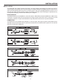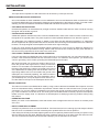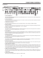
1
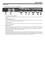
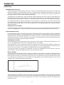
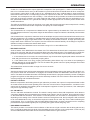
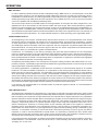
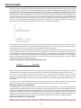
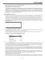
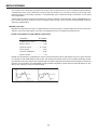
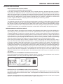
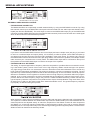
OWNERS MANUAL
¡
SAFETY RELATED SYMBOLS
protective grounding wire or disconnect the wiring of
protective grounding terminal.
# ! 5 4 )/ .
2) 3+ / & %, %# 42 )# 3( /# +
$/ ./ 4 /0 %.
• Operating Conditions
This apparatus shall not be exposed to dripping or
splashing and that no objects filled with liquids, such
as vases, shall be placed on this apparatus.
The symbol is used to indicate that some
hazardous live terminals are involved within
this apparatus, even under the normal
operating conditions.
To reduce the risk of fire or electric shock, do not
expose this apparatus to rain or moisture.
The symbol is used in the service
documentation to indicate that a specific
component shall be only replaced by the
component specified in that documentation
for safety reasons.
Do not use this apparatus near water. Install in
accordance with the manufacturer’s instructions.
Protective grounding terminal.
Do not install near any heat sources such as radiators,
heat registers, stoves, or other apparatus (including
amplifiers) that produce heat.
Alternating current /voltage.
Do not block any ventilation openings.
Hazardous live terminal.
No naked flame sources, such as lighted candles,
should be placed on the apparatus.
ON: Denotes the apparatus is turned on.
IMPORTANT SAFETY INSTRUCTIONS
OFF: Denotes the apparatus is turned off, because
it uses the single pole switch, be sure to unplug the
AC power to prevent any electric shock before you
proceed with your service.
• Read these instructions.
• Heed all warnings.
• Follow all instructions.
WARNING: Describes precautions that should be
observed to prevent the danger of injury or death to
the user.
• Keep these instructions.
Only use attachments/accessories specified by the
manufacturer.
CAUTION: Describes precautions that should be
observed to prevent danger of the apparatus.
• Power Cord and Plug
Do not defeat the safety purpose of the polarized or
grounding type plug. A polarized plug has two blades
with one wider than the other. A grounding type plug
has two blades and a third grounding prong. The
wide blade or the third prong are provided for your
safety. If the provided plug does not fit into your outlet,
consult an electrician for replacement of the obsolete
outlet. Protect the power cord from being walked
on or pinched particularly at the plug, convenience
receptacles, and the point where they exit from the
apparatus.
WARNING
• Power Supply
Ensures the source voltage matches the voltage of
the power supply before turning ON the apparatus.
Unplug this apparatus during lightning storms or when
unused for long periods of time.
• External Connection
The external wiring connected to the output hazard ous live terminals requires installation by an instructed
person, or the use of ready-made leads or cords.
• Cleaning
• Do not Remove any Cover
When the apparatus needs a cleaning, you can blow
off dust from the apparatus with a blower or clean
with a rag etc. Don’t use solvents such as benzol,
alcohol, or other fluids with very strong volatility
and flammability for cleaning the apparatus body.
Clean only with a dry cloth.
There are maybe some areas with high voltages inside,
to reduce the risk of electric shock, do not remove any
cover if the power supply is connected. The cover
should be removed by qualified personnel only.
No user serviceable parts inside.
• Fuse
• Servicing
To prevent a fire, make sure to use fuses with specified
standard (current, voltage, type). Do not use a different
fuse or short circuit the fuse holder.
Refer all servicing to qualified personnel. To reduce
the risk of electric shock, do not perform any servicing
other than that contained in the operating instructions
unless you are qualified to do so.
Before replacing the fuse, turn OFF the apparatus
and disconnect the power source.
Servicing is required when the apparatus has been
damaged in any way, such as the power supply cord
or plug is damaged, liquid has been spilled or objects
have fallen into the apparatus, the apparatus has
been exposed to rain or moisture, does not operate
normally, or has been dropped.
• Protective Grounding
Make sure to connect the protective grounding to
prevent any electric shock before turning ON the
apparatus. Never cut off the internal or external
CONTENTS
MAXCOM SPECIFICATIONS… ………………………………………………………………………… iii
AUDIO INPUT… …………………………………………………………………………………………… iii
INTRODUCTION…………………………………………………………………………………………… 1
FEATURE LIST………………………………………………………………………………………………………………… 1
THE DESIGN CONCEPT … ……………………………………………………………………………… 2
THE VCA… …………………………………………………………………………………………………………………… 2
inputs… ……………………………………………………………………………………………………………………… 2
INSTALLATION……………………………………………………………………………………………… 3
UNBALANCED/BALANCED OPERATION… ……………………………………………………………………………… 4
MAINS CONNECTION … …………………………………………………………………………………………………… 4
CONTROLS… ……………………………………………………………………………………………… 5
FRONT PANEL LAYOUT OF THE MAXCOM… …………………………………………………………………………… 5
REAR PANEL… …………………………………………………………………………………………… 7
THE BACK PANEL LAYOUT OF THE MAXCOM … ……………………………………………………………………… 7
OPERATION … …………………………………………………………………………………………… 8
EXPANDER/GATE SECTION … …………………………………………………………………………………………… 8
COMPRESSOR SECTION … ……………………………………………………………………………………………… 8
BBE SECTION …………………………………………………………………………………………………………………10
COMPRESSION EFFECT… …………………………………………………………………………………………………10
THE LIMITING EFFECT ………………………………………………………………………………………………………10
APPLICATIONS … ………………………………………………………………………………………… 11
MAIN APPLICATIONS AND INITIAL SETTINGS…………………………………………………………………………… 11
EXPANDER/GATE SECTION … …………………………………………………………………………………………… 11
THE COMPRESSOR FUNCTION……………………………………………………………………………………………13
LIMITER FUNCTION… ………………………………………………………………………………………………………14
SPECIAL APPLICATIONS… ……………………………………………………………………………… 15
THE MAXCOM AS A PROTECTIVE DEVICE………………………………………………………………………………15
EXTERNAL SIDECHAIN APPLICATIONS… ………………………………………………………………………………16
Service… ……………………………………………………………………………………………………………………19
Warranty… …………………………………………………………………………………………………………………19
Maintenance… ……………………………………………………………………………………………………………19
ii
SPECIFICATIONS
MAXCOM SPECIFICATIONS
AUDIO INPUT
Type… ………………………………Active balanced XLR and 1/4” jack
Impedance……………………………60k ohm balanced
Maximum input level… ……………+21 dBu balanced and unbalanced
AUDIO OUTPUT
Type… ………………………………XLR and 1/4” jack
Impedance……………………………1K ohm unbalanced
Maximum output level………………+21 dBu
Frequency response … ……………20Hz to 20KHz
THD N% @ 1kHz, 4dBu……………0.05%
IMD (SMPTE) @ 10dBu……………0.01%
Noise & Hum unity gain… …………93dBu
Noise & Hum, fully off… ……………97dBu
Crosstalk @ 20kHz… ………………85dBu
CMR @ 1kHz… ……………………60dB
COMPRESSOR SECTION
Type… ………………………………Interactive Compressor
Threshold… …………………………Variable from -40dB to 20dB
Ratio… ………………………………Variable from 1:1 to LIM
Attack … ……………………………Variable from 0.1ms to 200ms
Release………………………………Variable from 0.05s to 4s
GATE SECTION
Type… ………………………………Interactive Expander/Gate
Threshold… …………………………Variable from OFF to 15dB
SONIC MAXIMIZER SECTION
POWER SUPPLY……………………………AC 115V/230Vac 60/50Hz; DC 24V
DIMENSIONS… ……………………………483mm (W) x 217mm (D) x 44mm (H)
19.01˝ (W) x 8.54˝ (D) x 1.73˝ (H)
WEIGHT………………………………………3kg (6.61lb)
iii
INTRODUCTION
INTRODUCTION
Congratulations and thank you for your purchase of the BBE MAXCOM. You have acquired an extremely efficient
and universal dynamics processor. It’s unique circuit design makes MAXCOM the ultimate dynamics processor:
intelligent program recognition, interactive expander/gate and a fourth generation BBE® Sonic Maximizer™.
FEATURE LIST
• SONIC MAXIMIZER
Loudspeakers have difficulty working with the electronic signals supplied by an amplifier. These difficulties
cause such major phase and amplitude distortion that the sound reproduced by speaker differs significantly from
the sound produced by the original source.
In the past, these problems proved unsolvable and were thus delegated to a position of secondary importance
in audio system design. However, phase and amplitude integrity is essential to accurate sound reproduction.
Research shows that the information which the listener translates into the recognizable characteristics of a live
performance are intimately tied into complex time and amplitude relationships between the fundamental and
harmonic components of a given musical note or sound. These relationships define a sound’s “sound”.
When these complex relationships pass through a speaker, the proper order is lost. The higher frequencies are
delayed. A lower frequency may reach the listener’s ear first or perhaps simultaneously with that of a higher
frequency. In some cases, the fundamental components may be so time-shifted that they reach the listener’s
ear ahead of some or all of the harmonic components.
This change in the phase and amplitude relationship on the harmonic and fundamental frequencies is technically called “envelope distortion.” The listener perceives this loss of sound integrity in the reproduced sound as
“muddy” and “smeared.” In the extreme, it can become difficult to tell the difference between musical instruments, for example, an oboe and a clarinet.
BBE Sound, Inc. conducted extensive studies of numerous speaker systems over a ten year period. With this
knowledge, it became possible to identify the characteristics of an ideal speaker and to distill the corrections
necessary to return the fundamental and harmonic frequency structures to their correct order. While there are
differences among various speaker designs in the magnitude of their correction, the overall pattern of correction
needed is remarkably consistent.
• Interactive Compressor
The Interactive Compressor successfully combines the concept of a “Hard Knee” compressor with the characteristics of a “Soft Knee” approach. The “Soft Knee” mode with its “Soft” control characteristics is the basis of the
“inaudible” and “musical” compression of the program material, while the “Hard Knee” function is a prerequisite
both for creative and efficient dynamics processing and for limiting signal peaks reliably and precisely. This function is required to protect subsequent equipment against distortion.
• The AUTO function
The MAXCOM incorporates an AUTO function for intelligent program detection. With the help of the AUTO function, the attack and release times are derived automatically from the program material. Adjustment errors can
therefore be effectively prevented. This feature lets you compress the signal heavily and “musically” in dynamic
range without any audible “pumping”, “breathing” or other side effects, providing you with optimum results.
• Manually Adjustable ATTACK and RELEASE Controls
The response of a compressor and the quality of the dynamics processing largely depend on the control times, i.e.,
the attack and release functions. When processing signals from individual instruments such as drum, guitar etc.,
and when using the compressor to protect the audio system against signal transients, it is imperative that the control
times be user-adjustable. The MAXCOM offers this feature by providing both ATTACK and RELEASE controls.
• Adaptive EXPANDER/GATE
A basic problem in the use of a compressor is the fact that the noise floor is highly amplified during quiet sections
or when there are music pauses. This effect is exaggerated when the compression ratio is inappropriate. An
adaptive Expander/Gate has been integrated into the MAXCOM. The gate is automatically adjusted dependent
on the program material. The result is an expander which is less critical of adjustment and which is more tolerant
in the presence of those signals which appear slightly above the noise floor.
DESIGN CONCEPT
THE DESIGN CONCEPT
THE VCA
At the heart of the MAXCOM lies an industry standard state-of-the-art VCA (Voltage Controlled Amplifier). With
its excellent specifications (noise, THD, control feedthrough, linearity, slew rate and temperature stability) the
precision VCA used in the MAXCOM is considered one of the best in VCA technology. The “control feedthrough”
used in VCA terminology is a very critical parameter for the crosstalk of the control voltage into the audio path.
Slow changes of the control voltage lead to a slow DC offset at the audio output of the VCA and are mostly inaudible. Fast controls however, will result in awkward switching noise (“clicks”).
inputs
• BALANCED INPUTS
As standard, the MAXCOM comes with electronically servo-balanced inputs. This circuit design features automatic hum and noise reduction for balanced signals and thus allows for trouble-free operation even at high
operating levels. Externally induced mains hum etc. will be effectively suppressed. The automatic servo-function
recognizes the presence of unbalanced connectors and adjusts the nominal level internally to avoid level differences between the input and output signals (correction 6 dB).
• SIDECHAIN INPUTS
Each of the two channels of the MAXCOM incorporates a separate SIDECHAIN insert facility. Using an external
equalizer, this additional feature allows for frequency selective operation. Therefore, the unit can be used as a
de-esser or feedback suppressor.
• AUDIO PATH
The audio signal passes first through an electronically balanced input stage and is then directed through the
VCA which actually governs the dynamic process. The VCA’s output feeds the resulting signal into the Sonic
Maximizer. The subsequent potentiometers control the amount of Sonic Maximizer Process and Lo Contour
control which will be used in the main path. The amplifier and output driver leads the signal via the Bypass switch
to the output connector.
• SIDECHAIN PATH
The audio signal is simultaneously directed to the SIDECHAIN. By further processing of this input signal, both
Expander and Compressor Audio Detectors result in a conversion of the audio signal into rectified control voltages. The subsequent Auto Gate and Auto Compressor circuit govern the control characteristics of the gate
and the compressor. They automatically derive the attack and release times from the input signal and therefore
generate a musical and unobtrusive signal processing. The final control voltage is then routed to the VCA.
• SIDECHAIN INPUT
An external signal can be fed into the SIDECHAIN connector which allows the unit to be controlled externally. By
using the SIDECHAIN insert on the back panel the link to the audio signal will be automatically interrupted and
the MAXCOM can now be used for example as a frequency selective compressor (de-esser etc.).
INSTALLATION
INSTALLATION
Your MAXCOM was carefully packed at the factory and the packaging was designed to protect the unit from
rough handling. Nevertheless, we recommend that you carefully examine the packaging and its contents for any
signs of physical damage which may have occurred in transit. If the unit is damaged please do not return it to us
but notify your dealer and the shipping company immediately, otherwise claims for damage or replacement may
not be granted. Shipping claims must be made by the consignee.
• RACK MOUNTING
The MAXCOM fits into one standard 19” rack unit of space. Please allow at least an additional 4” depth for the
connectors on the back panel. Be sure that there is enough air space around the unit for cooling and, to avoid
overheating, please do not place the MAXCOM on high temperature devices such as power amplifiers.
• CONNECTORS
The MAXCOM can be installed using standard 1/4” and XLR jacks. Although the inputs are fully balanced, the
automatic servo-functions allow them to operate with unbalanced source/loads. Audio outputs use 1/4” and XLR
jacks also, but they are unbalanced.
INSTALLATION
• IMPEDANCE
The input has an impedance of 60k Ohms and can be driven by most input sources.
UNBALANCED/BALANCED OPERATION
90% of all mistakes in audio installations can be attributed to incorrect and defective audio connections! In order
to utilize the MAXCOM to its full potential, please pay special attention to the following section. For better understanding, the technical difference between unbalanced and balanced systems must be clarified:
• The Unbalanced System
Unbalanced operation is characterized by a single conductor shielded cable with the center conductor carrying
the signal and the shield at ground.
• The Balanced System
A balanced operation is defined as a two conductor shielded cable, where each of the two center conductors carry
the signal but of opposite phase. They have equal but inverted potential differences from that of the ground.
The advantage of the balanced system is based on the effect that the differential amplifier in a subsequent
device suppresses all equal phased noise which has been induced during its transmission down the cable link.
However, the original signal will be amplified and retain all its original integrity.
In this way audio signals can be transmitted without interference or loss across long distances. Balanced or
unbalanced systems require different wiring. Please read the next section carefully and pay close attention to
the correct wiring requirements of the units in the audio chain.
• The Correct Wiring For Balanced Operation
If the Unit preceding the MAXCOM uses output balancing we recommend that you use balanced audio connections. This will avoid interferences such as mains hum etc. For maximum hum rejection, you should avoid
common grounding, which means grounding the MAXCOM input and output.
We recommend that you connect the shield of the input cable to the ground of the signal source, making sure that the
shield is not connected to the MAXCOM input connector. At
the output, the shield of the cable is connected to the ground
of the MAXCOM, but making sure that the shield of the corresponding cable’s end is not connected to the ground of the
subsequent unit. Generally speaking, the shield connection
will be tied to the source units, but not to destination units. If
you still develop hum, it may be helpful is some cases to connect the shield on the input of the subsequent device also.
END UNIT
The correct wiring of the balance system
MAINS CONNECTION
The mains connection in the MAXCOM is made by using a mains cable and a standard IEC receptacle. It meets
all of the international safety certification requirements. Please make sure that all units have a proper ground
connection. For your own safety it is advisable not to remove the ground connection within the unit or at the supply, or fail to make this connection at all. The audio ground of the MAXCOM is internally capacitor decoupled to
isolate it from the supply earth. It is therefore not advantageous to attempt ground loop problem solving using
this method.
• Operating Voltage
Before you switch on the MAXCOM, check that the AC mains voltage match that one shown on the back panel
of the unit.
• Safety Fuse Replacement
A safety fuse protects the unit from serious defects. If the fuse blows, this is a warning sign and always indicates
that the circuit is overloaded. The fault must always be repaired before the fuse is replaced.
If the safety fuse is faulty and needs replacing after the unit is repaired, please make sure that you replace it only
with the identical type and rating. NEVER use fuses of different ratings or cover faulty fuses with aluminium foil.
This can cause fire and electric shocks and will endanger your life and the lives of others.
FRONT PANEL CONTROLS
CONTROLS
FRONT PANEL LAYOUT OF THE MAXCOM
-14
N
14
-30
2.5
-10
-15
-50
-70
0
-20
-30
0
50
2
5
10
8
1
10 1.5
0.5
100
0
1
0.3
0.1
150
2
N
6
-6
-14
N
N
N
N
N
2
N
0.1
150
6
-6
N
1
1
0.3
#(
N
14
N
8
10 1.5
100
N
N
10
N
N
N
-30
5
0
N
0
2
0.5
N
-70
0
-20
50
N
-15
-50
#(
2.5
-10
N
1
N
lim
2!4)/
0.1
MS
200
4
SEC
2%,%!3%
-20
D"
20
3
4
5
9
7
8
).
/54054
6
2
1
.05
!54/
!44!#+
N
20
N
D"
N
-40
#(!./.
'2
,).+
).
'2
OFF
D"
13 12
10
12 14 13
10
-40
#(!./.
D"
20
'!4%
4(2%3(/,$ 4(2%3(/,$
1
N
lim
2!4)/
0.1
MS
200
2
1
.05
!54/
!44!#+
4
SEC
2%,%!3%
-20
D"
20
/54054
6
3
4
5
N
10
N
D"
N
OFF
'!4%
4(2%3(/,$ 4(2%3(/,$
N
-30
N
-!8#/-
9
7
8
10 15
11
11
1. GATE/THRESHOLD
This control adjusts the threshold level for the expander/gate section in the range of off to 10dBu. Signals below
the set level are attenuated.
2. CHAN. ON switch
This switch activates the corresponding channel. The switch is used to make direct A/B comparisons between
original material and processed signal.
3. THRESHOLD control
This control sets the threshold point for the compressor section. It has a range of -40dBu to 20dBu.
4. RATIO control
The RATIO control determines the ratio between the input and output level for all signals exceeding the threshold point. The ratio range can be adjusted from 1:1 to 11:1 (Limiter).
5. ATTACK Control
The ATTACK control determines the rate by which the compressor responds to the signal which exceeds the
threshold. This control can be adjusted from 0.1ms to 200ms
6. AUTO switch
By activating the AUTO switch, the ATTACK and RELEASE controls are disabled and the attack and release
rates are automatically derived from the program material. This function allows for unobtrusive musical compression of signals or mixes with widely varying dynamics.
7. RELEASE control
The RELEASE control determines the rate that the compressor returns to unity gain after falling below the
threshold level. This control can be adjusted from 0.05s to 4s.
8. OUTPUT control
The OUTPUT control allows for the increase or decrease of the output signal by a maximum of 20 dB. Thus, a
level loss due to the compression or limiting process can be compensated for .
9. BBE ON/OFF SWITCH
This switch engages the BBE Process as indicated by the green LED. When in the “OUT” position the green
LED will not illuminate indicating that the BBE Process has been disengaged.
10. BBE PROCESS CONTROL
When the knob is in its minimum position, completely counterclockwise, no process is taking effect and the circuit
is in its noise suppression mode. Turning the knob clockwise will introduce the BBE Process. Adjust the knob to
mix the desired amount of process to suit your taste. Use the BBE as an extension of the tone controls. Generally
a good place to start the BBE process is to set the knob to it’s 12 o’clock position, then adjust accordingly.
11. BBE LO CONTOUR CONTROL
This control is a low frequency adjustment for the BBE Process. It provides a boost of 10dBu when turned to its
maximum position (clockwise) at 50Hz. When turned to its minimum position (counter-clockwise) no adjjustment
is taking place.
12. INPUT LEVEL METER
Shows level of incoming signal in a range from -20dB to +6dB.
FRONT PANEL CONTROLS
13. GAIN REDUCTION meter
The GAIN REDUCTION meter indicates the actual gain reduction and displays this in a range of 0dB to infinity.
14. LINK SWITCH
Engages the LINK function.
15. POWER SWITCH
REAR PANEL
REAR PANEL
THE BACK PANEL LAYOUT OF THE MAXCOM
1
2
3
4
5
3
4
5
1. AC JACK & AC FUSE HOLDER
Please note that, depending on the main voltage supplied to the unit, the correct fuse type and rating must be
installed.
2. AC voltage selector:
This selector allows choosing the supply voltage for the MAXCOM from either 115Vac or 230Vac. The supply
voltage can only be selected by a SERVICE CENTER.
3. OUTPUT JACKS
There are two audio outputs: XLR (wired: pin1&3 ground, pin2 high) and 1/4” jack (mono connector) for each
channel of the MAXCOM
4. input jacks
There is one XLR audio input (actively balanced and wired: pin1=ground, pin 2=high and pin 3=low) for each
channel of the MAXCOM. Additionally there is one 1/4” audio input jack for each channel which is actively balanced and are wired: tip =high(+), ring=low(-), and sleeve=ground. When a mono unbalanced connection is
made this jack is wired: tip = high(+), and sleeve=ground.
5. SIDECHAIN INSERTs
These are the insertion point which enable the unit to be controlled externally. You can use the connector as a
pure input (mono jack connector) or as an insert (stereo jack connector). In this case please use a special insert
cable which splits up one stereo into two mono jack connectors. The ring of the SIDECHAIN connector carries
the units output signal and the tip receives the processed signal from an external unit.
OPERATION
OPERATION
EXPANDER/GATE SECTION
A downward expander automatically reduces the overall level for all signals below the threshold. The expander
therefore operates in the opposite way to that of a compressor/limiter. Expanders generally function with a flat
ratio curve in that the signal continually fades. Noise gates, however, can be seen as “high ratio” expanders. If
the signal falls below he threshold it is radically attenuated.
The MAXCOM is equipped with a newly developed Adaptive Expander, the ratio of which is automatically adjusted dependent on the program material. The response characteristics of conventional expanders tend to cut
into the signal abruptly and the result of this is unacceptable most of the time. Gain changes become audible.
The Adaptive Expander is therefore equipped with a soft, interactive, nonlinear ratio curve which is best suited
to human hearing. Critical signals in the vicinity of the threshold level are processed with a minute expansion
ratio whereas signals that reduce in level will be subjected to an increasingly higher ratio, which will result in
greater attenuation.
• THRESHOLD adjustment
The threshold control of the Expander/Gate stretches across a very wide range and therefore applies to all working
levels. If the THRESHOLD control is turned fully counterclockwise, the Expander/Gate section is inoperative.
COMPRESSOR SECTION
In the MAXCOM, control of the dynamics process is achieved by means of a high quality VCA with an operating
range of more than 60dB, i.e. the input signal level can be reduced or increased within a range of 60dB. Input
signal levels below the adjusted threshold are not reduced. However, as soon as the input signal exceeds the
threshold level, dynamic control is activated. The amount of compression (gain reduction) is proportional to the
amount by which the input signal exceeds the threshold.
• THRESHOLD control
The THRESHOLD control determines the point at which a certain input level causes the level reduction to commence. The THRESHOLD control has an operating range of -40 to 20dBu.
If the THRESHOLD control is set fully clockwise, this corresponds to a threshold level of 20dBu. In practice, this
threshold level cannot be reached as the unit would overdrive. This control setting allows the Compressor section to be put out of action if, for example, the Expander/Gate is to be used independently.
The degree and type of compression is determined not only by the THRESHOLD control, but also by the subsequent RATIO, ATTACK and RELEASE controls and by the AUTO switch.
• RATIO control
The RATIO control determines the ratio of change in output level compared to input level, for all signals exceeding the threshold. The scale of the ratio is calibrated in dB on the front panel. It indicates the increase in input
level required, to produce a 1 dB increase in output Level. In the Introduction chapter we described the function
of a compressor by comparing it to a volume fader where signal peaks are controlled manually in order to avoid
distortions due to signals exceeding the threshold.
Fig.11 The ratio of input to output level with reference to different ratio settings
There are two ways to utilize this level control: either the output level is limited in such a way that no signal can
exceed a predefined maximum or the output level is reduced above the threshold, so that signal peaks may well
exceed the threshold, but are reduced proportionally. The extent of this change in dynamics is determined by
the RATIO control.
operation
A ratio of 1:1 indicates that the output signal will correspond to the input signal i.e., there is no level change. A
ratio of 2:1 indicates that for every 2 dB increase in input level above the threshold there will be a corresponding increase in output level of 1dB. A ratio of 10:1 indicates that for every 10dB increase in input level above
the threshold there will be a corresponding increase in output level of 1dB, etc. If the RATIO control is set fully
clockwise, this corresponds to a ratio of infinity:1. This means that all input levels are reduced to the threshold
point and are thus kept constant. It is worth observing that a hard or infinite-ratio limit has applications in certain specialized situations, but in general this setting is neither appropriate nor necessary as this would cause
audible side effects.
The effect of the RATIO control can be shown on a graph which plots input level versus output level. It clearly
shows that below the threshold the compressor acts purely as a linear amplifier.
• ATTACK Control
The characteristics of a compressor are determined to a great extent by the attack time. This is the amount of
time that elapses before the compressor begins to attenuate the output level after the threshold point has been
exceeded.
A short attack time is required for transients such as handclaps and percussive instruments like snare drums so
that the compressor is in a position to regulate these types of peaks. With other kinds of program material it can
be advantageous to apply longer attack times. It is always recommended, however, to begin processing with
longer attack times. Whenever it is required, the time should be reduced carefully as the danger of dynamics
distortion usually increases with shorter attack times.
The attack time of the MAXCOM can be set within a range of 0.1 to 200 milliseconds.
• RELEASE control
Another feature of the MAXCOM is the release time. This determines the time that the compressor requires to
return to its unity gain after the input signal has fallen below the threshold point. The release time is largely dependent on the program material. If the time is incorrectly set, this can lead to two fundamental problems:
1 - If the release time is too short, the overall volume may fluctuate when signals peak above the threshold
level and give the sound an unpleasant pumping effect.
2 - If the release time is too long, pumping and breathing side effects may occur when a loud passage is
abruptly followed by a quiet passage. The VCA increases the general volume of quiet passages which leads
to a disadvantageous tonal effect.
The release time can be set within a range of 0.05 to 4 seconds.
• AUTO SWITCH
Attack and release times are important parameters which significantly influence the quality of the dynamic control process. When the AUTO switch is engaged, the manual ATTACK and RELEASE controls are put out of
action. The attack and release times are automatically derived from the program material by means of intelligent
program recognition so that setting errors can be effectively avoided. The AUTO function eliminates side effects
such as pumping and modulation distortion.
• OUTPUT control
Because compression and limiting are both gain reduction processes, the output of a compressor/limiter is often
at a lower level than the normal operating level. This loss of level must be compensated for. A reduction in the
output level is required if the operating level of subsequent equipment is lower (for instance, if the subsequent
unity has a high sensitivity input).
• CH. ON switch
The CH. ON switch activates the channel. The switch is mainly used for direct A/B comparisons, which allows a
comparison between the unprocessed and processed signal. When in the OUT position, all processing functions
on the MAXCOM are turned off. If the switch is in the ON position, the unit work as a Compressor or Limiter,
depending on the setting of the controls. Please note that in the bypass mode, the input signal is still connected
to all of the MAXCOM circuitry, so that all the required controls can be used “Dry” that is without affecting the
original signal. This, in conjunction with the GAIN REDUCTION meter, provides a powerful tool for comparing
processed and unprocessed signals prior to operating the bypass switch and going “live”.
• GAIN REDUCTION meter
This meter provides a convenient visual indication of the amount of gain reduction that is taking place at any
time. If a signal exceeds the input level of the threshold point this function of the Compressor comes into play
and the GAIN REDUCTION meter shows the actual measurement of gain reduction.
OPERATION
BBE SECTION
In order to address problems inherent in basic loudspeaker design, BBE Sound, Inc. has developed a circuit that
has two primary functions. The first adjusts the phase relationship of the low, mid and high frequencies. Since a
loudspeaker¹s natural tendency is to add progressively longer delay times to higher frequencies, the BBE circuit
adds progressively longer delay times to lower frequencies. This creates a kind of “mirror” curve to the time delay
curve in the speaker and neutralizes its distorting effect.
The second major element in the BBE system is the augmentation of the higher and lower frequencies. Loudspeakers tend to be less efficient in their extreme treble and bass ranges. Most sound-reproducing systems
include a circuit for boosting high and low frequencies, showing an accepted awareness of the loudspeaker¹s efficiency problem. The BBE system, however, provides a dynamic, program-driven augmentation which combines
with the phase compensation feature to restore the brilliance and clarity of the original live sound. The result is, as
one professional journal phrased it, “The most hearable advance in audio technology since high fidelity itself!”.
COMPRESSION EFFECT
At the beginning of this chapter, we dealt briefly with the basic functions of a compressor/limiter. Now we will
discuss this point in more detail, with reference to the threshold setting, input level and compression: consider
an input signal which is applied to the inputs of two compressors. The threshold of the second compressor is
set 10 dB higher than the threshold of the first compressor. Since a compressor only affects signals that exceed
the threshold level, it is fairly obvious that the signal of the first unit, will be compressed more because as the
threshold is lower, it is exceeded to a greater exceeded before.
Furthermore, it is interesting to note that by comparing the input and output waveforms for the compressed
mode, the quietest sections of the input signal have been effectively raised in level, whereas the loudest sections have been effectively decreased in level. The overall effect is that both ends of the dynamics range have
been pushed towards the middle. The squashing effect of compression is important to remember and highlights
the major difference between compressing and limiting.
Compressing and limiting differ in one more aspect: the dynamic setting for attack and release times. For compression purposes, a preferably longer attack and release time is generally the best in order to keep the overall
output signal within a specified dynamic range.
For limiting applications, considerably shorter times are necessary to control transient signals or to increase
headroom. To achieve inaudible compression, it is imperative to work with program dependent attack and release times and a Soft Knee response. The advantage of program dependent compression is most apparent
when processing musical material that is varied. The MAXCOM is suitable for all applications because of its
various time settings and the AUTO processor. With the AUTO switch engaged, the unit uses program dependent attack and release times. When not engaged, the control times can be set manually. Please note, while the
AUTO switch is depressed the MAXCOM does not provide a limiter function even if the RATIO control is turned
fully clockwise because signal peaks are NOT radically cut off above the threshold point.
If you want to use the MAXCOM as an ultimate means of protection against overload, it is recommended to
study the following chapter.
THE LIMITING EFFECT
The attack time is defined as the time taken for a compressor to respond to program levels which have exceed
the threshold point. Because of the physical relationship between frequency and slew rate, the resulting factor is
that for relatively low frequencies a longer attack time was required than for higher frequencies: any unpleasant
dynamic distortion would be avoided. When compressing a program mix that includes a wide range of frequencies, a compromise must be made when setting the attack time. This setting would generally suit the lowest
frequency components present. For general dynamic-range control using the compressor mode, this is of no
serious consequence. However, in a limiting mode, we are restricting the peaks of our signals to a maximum
operating level to avoid distortion in any subsequent devices. If we are using a conventional compressor in a
limiter mode, the result will be in very fast high frequency signal transients passing through unaffected by gain
reduction. It is therefore necessary to choose the limiter control times precisely in order to govern any kind of
transients. In order to use the MAXCOM as a peak limiter, it is necessary to operate the unit in limiter mode
(RATIO control turned fully clockwise) and to switch out the AUTO function. This enables the limiter function to
exclusively and instantaneously respond to signals which exceed the threshold level.
It is important that the AUTO switch is switched off and that the attack time is as short as possible to avoid any
audible distortion. The RELEASE control should be set to a value whereby side effects such as “flutter” and
“pumping” etc. do not occur.
10
APPLICATIONS
APPLICATIONS
In this section several typical applications of the MAXCOM are discussed. The following basic settings can
resolve most dynamic problems. They are the ideal starting point. Please take the time to study the application
examples carefully to make full use of the MAXCOMs capabilities in the future.
MAIN APPLICATIONS AND INITIAL SETTINGS
The main applications of the MAXCOM can be divided into four categories:
1 - The Expander/Gate section is used to eliminate interference and to suppress background noise and leakage
on individual tracks in multitrack recording.
2 - The Compressor section is used to compress the program material and to create special effects and unusual
sounds, which are used for recording and musical performance.
3 - The Limiter function is designed to protect loudspeakers, recorders, transmitters etc. from signal peaks, short
term over-loading and over modulation (transmitters etc.).
4 - The BBE SONIC MAXIMIZER function is designed to improve the clarity and openness of any sound source
or sound system application.
Now that the functions of the individual sections have been clearly explained, we would like to acquaint you with
more terms and relationships of the dynamics process.
• Compression
A compressor converts a large dynamic level into a restricted range. The extent of the resulting dynamic level
is dependent on the threshold, attack, release and ratio settings. The faster the chosen control times and the
higher the compression ratio, the greater the effect on the short term dynamics. This fact is often used to achieve
audible and creative sound effects.
• Levelling
The levelling mode is used to keep output level constant, i.e. to compensate for long term gain changes without
affecting the short term dynamics. Normally, the threshold is set quite low in order to be able to increase low
level signals. Levelling requires slow attack and release times combined with a high ratio. Because of the very
slow response time, levelling has no effect on signal peaks or short term changes in average level.
• Limiting
The limiting function requires a fast attack time and a high ratio and release time setting, which is dependent on
the specific use. As it is usually the task of a limiter to limit only high signal peaks, the threshold is usually set
at a high level. The dynamics are reduced dependent on the ratio setting and the degree by which the threshold point was exceeded. If the attack time is adjusted to control only the average level without affecting signal
peaks above the threshold, then it is referred to as a Program Limiter. For this purpose the attack time will be
set above 20 ms. If the attack time is further reduced in order to also control signal peaks, then it is defined as
a Peak Limiter.
• Clipping
In contrast to the two previously mentioned limiters, the clipping mode features infinitely fast control times, an
infinite compression ratio and creates a “brickwall” for all signals above a certain level. To be able to control the
signal peaks, the clipping function radically cuts signals above the threshold without affecting the amplitude of
the original signal. If used in normal applications, this function remains inaudible and under certain circumstances it can even lead to an improved sound because cutting the transients creates artificial harmonics. If misused,
clipping can cause very obvious and distasteful distortion, which in an extreme manner will convert the signal’s
waveform into a square wave.
EXPANDER/GATE SECTION
The main task of the Expander/Gate is to “inaudibly” eliminate undesirable background noise from the usable signal. This assumes that there is a slight level difference between the usable signal and the noise floor, in order to be
able to define the operating threshold of the Expander/Gate. At the same time, the Expander/Gate must respond
very quickly (have a very fast attack time) so that the signal’s leading edge remains unaltered. When expansion
occurs there are no common side effects due to the extremely smooth and unobtrusive action of the circuit.
• Controlling Leakage In The Studio
Expander/gates are most commonly used to suppress undesirable leakage of sound from one track to another
11
APPLICATIONS
during recording or playback. They are usually used when recording drum kits, where the mics are very close to
each other. High volume levels of individual instruments often cause considerable leakage onto all the adjacent
mics and results in conflicting frequency and phase coherence problems, as well as unspecified sounds (“comb”
filter effects). It is vitally important that every instrument is recorded into a separate mic and that each mic is individually gated. Patch the MAXCOM into a snare drum channel for example and adjust it so that triggering only
occurs on snare hits. Each mic should be set to its maximum operating level, monitored and the THRESHOLD
level set so that each snare hit sounds acoustically clean and separate, as though it was played on its own. The
optimum use of the Expander/Gate depends principally on microphone technique. Be particularly careful when
high frequency instruments are located to the side or rear of a cardioid microphone.
Function of an expander
Fig.9 Function of an expander
Most cardioids exhibit a sharply rising off-axis response characteristic at higher frequencies. If there is only a 2
or 3 dB difference between the on-axis and off-axis response in the 5 to 10 kHz region, cymbals may leak excessively into the tom mics and you may have hi-hat spilling all over the snare mic.
Please make full use of the directional characteristic of the mics to acoustically exclude all other instruments as
much as possible. Make sure that you do everything possible to achieve source separation with good microphone technique. Otherwise the Expander/Gate is not able to undertake clear acoustic separation. Sometimes,
it is necessary to prevent the Expander/Gate from responding to low frequencies (rumbles etc.), especially if a
singer is moving the microphone around on a mic-stand. More information about this topic in section “USING
AN EQUALIZER IN THE SIDECHAIN PATH”.
• Initial Settings For The Expander/Gate Section
CONTROL SETTINGS
GATE THRESHOLD control -70 dB
Begin with very low threshold levels so that the signal can pass through the unit unaffected. Now turn the control
clockwise until all unwanted noise is removed and only the sound of the desired instrument can be heard.
If the control is set correctly, the drum sounds will be “dry”, “sharp” and clearly defined. If you do not have
enough mics (or MAXCOM channels!) to record each instrument separately, try to create subgroups: put the
snare and mid-toms together, and group the side-toms, bass drum and cymbals together with the help of a mixing console.
The aim is to set up the Expander/Gate and to position the group mics so that each strike on an instrument
opens a specific mic and so only that instrument is recorded, whilst the other mics remain “muted”.
• Reducing Leakage In Stage Mics
The MAXCOM has many uses in live work. On stage and in multi-miking situations, a well set up Expander/Gate
can effectively suppress background noise, compressor type pumping noise and microphone leakage without producing any undesirable side effects. Expander/gates are commonly used for processing vocals. When specifically
used with a compressor, the distance and position of the mic in relation to the singer is very critical: the further the
distance, the more sensitive the mic is to background noise. When used in live situations, leakage of miked instrumentation is substantially reduced, as well as other acoustic contaminants in various recording situations.
• Reducing Feedback In Stage Mics
When a singer is using a vocal mic, their voice effectively stops other sounds from entering the mic. But in
pauses between the singing, the mic will pick up noise from the house PA and monitors which can lead to un12
APPLICATIONS
pleasant feedback problems. If the MAXCOM is inserted into the mic channel, it will shut off the channel when
it is not being used reducing the possibility of feedback.
• Noise Reduction On Effects Paths
The effects rack is one of the most overlooked sources of noise in a PA system or recording facility. The price of
reverb and delay units and harmonizers has fallen drastically over the last number of years, which have made
these units a common feature in small studios and home recording installations. However, multiple effects units
considerably increase the overall noise level, so that the pleasure in acquiring a new sound effect is short lived.
It will prove useful to use the MAXCOM as the last component in the chain of effects units and use the noise
reduction function of the Expander/Gate section.
THE COMPRESSOR FUNCTION
The task of a compressor is to reduce the dynamic range of program material and to control the overall level. The
extensive controls of the Compressor section provide a great range of dynamic effects: from musical and soft
compression to limiting signal peaks, right up to extreme and effective compression of the overall dynamics.
For example, a low ratio and very low threshold setting can be used to achieve soft and musical processing of
the general dynamics of the program material. Higher ratios, together with low threshold settings, create relatively constant volume (levelling) for instruments and vocals. High threshold levels generally limit the overall
level of a program.
Fig.12 The effect of a compressor can be expressed as the amount
of gain reduction that is taking place for any given input
Ratios greater than 6:1 effectively prevent the output level from signals significantly exceeding the threshold
point (provided that the OUTPUT control is in the 0 dB position).
The AUTO function prevents aggressive compression, created by high ratios, from sounding too unnatural.
• Initial Settings For The Compressor Section
CONTROL SETTINGS
THRESHOLD control … ………+20 dB
RATIO control…………………… 2.5:1
AUTO switch… ……………………… IN
OUTPUT CONTROL……………… 0dB
IN/OUT switch………………………… IN
Rotate the THRESHOLD control counterclockwise until an appropriate amount of gain reduction is indicated
on the GAIN REDUCTION meter. This operation will be accompanied by an audible drop in output level. The
OUTPUT control should now be turned clockwise to reinstate the output level. The level of the unprocessed and
the processed signal can be compared by pressing the IN/OUT switch.
Final adjustments of the controls can then be made to suit your particular requirements, including the RATIO,
ATTACK and RELEASE controls. The AUTO function provides program dependent dynamic processing which
suits most standard uses. If a “condensed” or “wider” sound processing technique is required the attack and
release times can also be manually adjusted.
The experienced user will be in a position to specify parameters while in bypass mode and thus realize the effect
before the unit is actually switched into operation. This is important in live situations, where a signal needs to be
managed efficiently by the engineer without the convenience of continual A/B comparison.
• The maxcom As A Sound Effects Unit
In the early 1960’s musicians began looking at the recording process as a way to create new sounds. The
pumping effect which had been avoided by earlier engineers suddenly became fashionable and was utilized
13
applications
as a creative tool, laying the groundwork for many of the sounds which are now considered indispensable in
contemporary music. The compressor is used in this role because you can hear it working, and control of the
dynamic range is of secondary importance. The MAXCOM, with its extensive range of functions, is well suited
to this application.
Sound effects of this kind can be achieved using “extreme” settings. To achieve this, set the THRESHOLD control to a fairly low level, the RATIO control to almost maximum and use the ATTACK and RELEASE controls to
obtain the desired effect.
LIMITER FUNCTION
Besides the compressor function, the MAXCOM can be used to limit the overall output level and to protect subsequent units from signal peaks, short term overloading and over modulation (transmitters etc.).
• Initial Settings For The Limiter Functions
CONTROL
SETTINGS
THRESHOLD control……………+20 dB
RATIO control……………………… LIM
ATTACK control……………… 0.1 msec
AUTO switch… …………………… OUT
OUTPUT CONTROL……………… 0 dB
IN/OUT switch………………………… IN
Rotate the compressor’s THRESHOLD control counterclockwise until an appropriate amount of gain reduction
is indicated on the GAIN REDUCTION meter. The attack and release times can be modified manually. Please
pay attention to the fact that too short attack times can lead to distortion and long times let dangerous transients
pass the unit unhindered. The RELEASE control should be adjusted to values which avoid side effects as “fluttering” and “pumping” of the processed signal.
The signal BEFORE gain control and AFTER limiter processing
14
SPECIAL applications
SPECIAL APPLICATIONS
• USING THE MAXCOM FOR RECORDING
1. The MAXCOM In Digital Recording And Sampling
In an analog recording low recording levels lead to an increased noise level, whereas high levels will cause a
compressed and “squashed” sound. In contrast to analog, side effects in digital always become extremely audible: with decreasing level, a recording with insufficient level loses resolution: the recording sounds “hard” and
loses “atmosphere”. With excessive level, the recording sounds harsh and heavily distorted. In order to avoid
these effects, the MAXCOM as a limiter should be placed before, for example, a sampler. As a result of this
process, a digital recording or a sampling event can be optimally set without any problem.
2. The MAXCOM In Mastering
The mastering process is one of the most critical processing steps in recording. In this production step it is the goal
to achieve a “maximum level” copy of the recording, without any noise or distortion. In many applications it is further required to produce a high average volume. Quite often in these cases, dynamics suffer drastically, because
the program material has been compressed and limited too heavily. Using the Compressor section of the MAXCOM as a limiter allows you to drastically increase the overall volume without audibly affecting the dynamics.
THE MAXCOM AS A PROTECTIVE DEVICE
Sound system distortion is usually a result of amplifiers and loudspeakers being driven beyond their limitations by
signals clipping. The signal limitations that occur lead to unpleasant distortion that is dangerous to the speakers.
A speaker diaphragm is required to accelerate, slow down, smoothly change direction and accelerate again in
normal operation. Distorted operation (clipping) leads to instant acceleration, instant stop, change of direction and
instant acceleration again. Since speaker diaphragms are subject to the laws of physics, they will not take this kind
of punishment for long: the diaphragm will either break up or its voice coil may overheat. In addition to the damage
caused by sustained overload, the speaker may also be damaged by an occasional high level overload.
Even if this type of transient does not destroy a speaker outright, it may damage the speaker surround in such a
way as to cause mechanical abrasion and future failure. It is recommended that you use the MAXCOM in order
to protect the speaker. “Brick Wall” peak limiters are not normally necessary for PA systems, as amplifiers and
loudspeakers are tolerant of short signal peaks. Nevertheless, conventional limiters have to be generally driven
far beyond the headroom limit of an amplifier in order to limit the level and length of the transients responsible for
overloading the system. The disadvantage of this principle is that the unit’s full range cannot be completely used.
If an increase in the average level of up to 3 dB is attained with the MAXCOM as a Limiter, this means that you
effectively double the power amplification. The MAXCOM can act in this way to convert a PA system of 5,000
Watts into a distortion free 10,000 Watt system. The following instructions will help you to integrate the unit into
your system.
• Protection Of A System With A Passive Crossover
If your sound system incorporates a passive crossover network (included in the loudspeaker case), insert the
MAXCOM between your mixing console output and the power amplifier input.
AMP
MAXCOM
Integrating the MAXCOM into a system with a passive crossover network
• Protection Of A System With An Active Crossover
For systems using active crossovers, there are two ways to use the MAXCOM. The unit may be inserted between the console output and the crossover input. In this application, the MAXCOM will process the entire audio
frequency spectrum.
Alternately, the MAXCOM can be inserted between the output of an active crossover and the input of a power
amplifier. In this application it will only affect a specific range of frequencies.
15
SPECIAL applications
The MAXCOM in a two way system
EXTERNAL SIDECHAIN APPLICATIONS
• THE SIDECHAIN CONNECTOR
The MAXCOM offers an exceptionally versatile external facility by using the SIDECHAIN connector. By using
this external control input, the MAXCOM control path is disconnected from the audio input and therefore interrupted (see “BLOCK DIAGRAM”). The audio input is routed to the SIDECHAIN output (ring of the SIDECHAIN
connector) and the SIDECHAIN input (tip of the SIDECHAIN connector) it will now receive the new control signal
which is derived from an inserted effects processor.
If you want to use the SIDECHAIN connector as a control input just insert a simple mono jack plug. If you intend
to use it as a combined input and output (insert), it is necessary to utilize a special “insert cable” that splits up
one stereo jack plug into two mono jack plugs and is available in most music stores. The stereo end is used for
the SIDECHAIN connector while the two mono jack plugs will be connected to an equalizer, for example. Please
make sure that your connections are correctly made. The SIDECHAIN output will be connected to the input of
the equalizer and the SIDECHAIN input is routed to the output of the equalizer.
• The MAXCOM As A “De-Esser”
“De-essing” is a special application of frequency selective compression. A problem often encountered in recording is the sibilant (“Ssss”) sound of the human voice. High frequency sibilant sounds and pops can produce
very high energy levels which can sometimes cause an otherwise normal and undistorted voice to sound very
harsh, shrill and sometimes unintelligible. The solution is frequency conscious compression or limiting. The unit
responds only to selected frequencies and reduces the level temporarily, as soon as sibilant sounds or pops are
detected. If the detector circuit registers an excessive amount of high frequency information within the program
material, as in a normal compressor, the VCA is activated and the overall level is reduced. As this type of compression affects the whole frequency range, this process is called broadband de-essing. Please note that this
type of frequency selective compression is very different from simple, fixed equalization using notch filters, since
de-essing has no effect on the signal except at the instant the sibilant occurs. The general frequency response
is principally not affected during this process.
When de-essing, simply insert an equalizer not into the audio path but into the sidechain path of the MAXCOM.
The equalizer is inserted between the SIDECHAIN output and the SIDECHAIN input of the MAXCOM and its
center frequencies are adjusted exactly to match the frequencies of the sibilant sounds. All other frequencies
are filtered out, so that with maximum attenuation of these frequency bands, along with a correctly adjusted
threshold point, the unit responds solely to the selected signal being produced by the equalizer. The level of the
sibilant sounds can therefore be effectively limited.
16
special applications
• Initial Settings for the De-Esser Functions
CONTROL
SETTINGS
EXP. THRESHOLD control… …… OFF
THRESHOLD control……………+20 dB
RATIO control……………………… LIM
ATTACK control……………… 0.1 msec
AUTO switch… …………………… OUT
OUTPUT CONTROL……………… 0 dB
PROCESS control…………………… IN
1 - Turn the THRESHOLD control counterclockwise until the GAIN REDUCTION meter shows an appropriate
drop in level.
2 - Now adjust the equalizer corner frequencies (generally 6 - 10 kHz) until it is within the range of the sibilant.
3- Recalibrate the THRESHOLD control, so that the unit reacts only when the sibilant sound occurs. Level compensation using the OUTPUT control is not necessary. Although the recommended attack and release times for
this function are proven, the time parameters can be adjusted if necessary to achieve maximum results. The
AUTO function should not be used.
• Frequency Selective Filtering Of Unwanted Signals
Based on the setup described in the de-esser section, the unit may also be used to eliminate rumble, hum and
equipment noise (air conditioning systems, camera noise etc.). Adjust the frequencies of the equalizer to match
the unwanted frequencies and use a peak filter with a high slope. Take care to decrease the amplitudes of the
unrequired frequencies.
Proceed now as described in the previous section “the MAXCOM As A De-Esser”. This will result in compression
of the selected frequencies and thus a decrease in the gain of the program material.
• Suppressing Instruments During Recording
Another function of the MAXCOM allows helpful correction of previously recorded material. If, for example, an excessively loud bass drum needs to be suppressed, reduce all the equalizers frequency bands above 150 Hz. This
setting causes frequency specific compression, which reacts as soon as increased energy is detected in this band.
By increasing the threshold level, the compression can be made to react only to loud pedal or stick actions.
• EMPHASIZING MUSICAL INSTRUMENTS DURING RECORDING
You can use the MAXCOM to bring out an instrument solo or a lead vocal in a cluttered mix. Match the frequencies of the equalizer to the frequencies of the instruments to be emphasized and for this it is best to use
a notch filter with a high slope. Please make sure that in this application, you only reduce the amplitude of the
selected frequencies.
The compression results is a subjective decrease in the volume of the overall program material.Only the selected frequencies coming from the equalizer remain uncompressed and are therefore perceived as being louder.
This inverse type of compression also helps to emphasize instruments during low level passages, so that they
become more pronounced.
• Reducing Feedback in PA Systems
A common procedure in sound system setup is equalizing the acoustics to remove feedback. This is generally
accomplished by turning up the system gain to purposely induce feedback, searching for the centre frequency
of the feedback and then attenuating at that frequency to remove the feedback. Once this feedback has been
attenuated, the system gain is again increased to induce another feedback point and the whole procedure is
repeated until the engineer is satisfied that the relevant problem frequencies have been corrected. In spite of this
17
special applications
equalizing process, feedback remains a difficult problem. Often enough, acoustic changes occur as the audience enters the room, which again leads to feedback problems. In addition, the frequency response of the whole
system is modified and thus affected by equalizer operation. Dynamic feedback control is a better solution.
Similar to the previously mentioned de-esser application, an equalizer is not inserted into the audio path but into
the sidechain path of the MAXCOM. To effectively suppress feedback, the centre frequency of the equalizer is
correctly adjusted to match the room’s resonant frequency. This selected frequency now controls the MAXCOM.
The signal coming from the equalizer is applied to the SIDECHAIN input, while the audio signal is routed through
the MAXCOM audio path. As soon as feedback occurs, the unit temporarily reduces the system gain and thus
effectively suppresses the feedback. In contrast to the technique mentioned above,the frequency response of
the PA system is not affected in any way at all.
• “VOICE-OVER” COMPRESSION (“DUCKING”)
The MAXCOM can be used to automatically reduce music to a background level, when an announcer is speaking through a microphone. For this purpose, the MAXCOM is used as an automatic fader and is controlled by
the announcer’s microphone, which is connected to the SIDECHAIN input via a preamplifier.
The music output and the announcer’s voice, are then mixed. This application is known as “voice over” compression or “Ducking” and is commonly used in discos, radio stations, etc.
• ANTICIPATED COMPRESSION
If you feed the audio signal directly into the SIDECHAIN input and send the audio signal through a delay before the
audio input, the MAXCOM can anticipate the need for gain change. With experimentation, the effect can create a
“zero” attack time at a given frequency. Additional delay beyond this “zero” attack time will produce a special sound
effect, similar to the dynamic envelope inversion you may already be familiar with from reverse tape playback.
18
SERVICE/WARRANTY/MAINTENANCE
Service
We recommend that if at all possible, a BBE MAXCOM which requires service be sent to our facility in Huntington Beach, California. We request that a “RETURN AUTHORIZATION” be issued by the dealer from whom
you purchased the unit. If this is not possible, call BBE Sound, Inc. directly at (714) 897-6766, extension 116 to
obtain a “RETURN AUTHORIZATION”. Include a copy of the bill of sale with the unit when it is shipped to BBE
Sound, Inc. so that the service can be expedited.
As the repair turnaround time is minimal, we request that the unit be sent to BBE Sound, Inc. We also need to
add reliability data to our files so that future revisions may be undertaken, if necessary, to improve the product.
If unit has been purchased outside the US, please contact your national distributor.
Warranty
Warranty registration of the unit to BBE Sound, Inc. is not necessary. It is strongly recommended that you retain
a copy of the bill of sale for future reference.
IT IS THE SOLE RESPONSIBILITY OF THE END USER TO PROVIDE THE BILL OF SALE OR OTHER MEANS
OF PROOF OF PURCHASE TO VALIDATE THE WARRANTY IF WARRANTY SERVICE IS REQUESTED.
The BBE MAXCOM is warranted against defects in material and workmanship for a period of two (2) years from
date of purchase from BBE Sound Inc. or from an authorized dealer. During this period, we will repair units free
of charge providing that they are shipped prepaid to BBE Sound, Inc., 5381 Production Drive, Huntington Beach,
CA 92649. We will pay return UPS shipping charges within the USA. All charges related to non-UPS shipping,
including customs clearance, will be billed. The warranty will be honored for the longer of either 90 days from
the date of any service or the remainder of the original 2 Year factory warranty.
This warranty will be consider null and void by BBE Sound, Inc. if any of the following is found:
1. The equipment has been physically damaged.
2. The equipment shows signs of abuse.
3. The equipment has been electrically damaged by improper connection or attempted repair by the customer
or a third party.
4. The equipment has been modified without authorization.
5. The bill of sale indicates that the purchase date of the equipment is not within the warranty period.
All non-warranty repairs are warranted for a period of 90 days from the date of service.
BBE Sound, Inc. is NOT LIABLE FOR CONSEQUENTIAL DAMAGES. Should the unit fail to operate for any
reason, our sole obligation is to repair it as described above.
DO NOT RETURN ANY PRODUCT TO THE ABOVE ADDRESS WITHOUT INSTRUCTIONS AND AUTHORIZATION ISSUED BY THE ABOVE LOCATION.
Maintenance
Maintenance of the BBE MAXCOM is limited to proper cleaning of the unit with mild household cleaner such as
Formula 409™ or Windex™. The chassis, front panel and cover are steel finished with a durable polyurethane
paint.
There are no user replaceable parts and the unit should not be opened for any reason unless you are a qualified
technician. Calibration should be performed if parts are replaced or if a performance check-out indicates a problem with calibration. Long term use has shown that over the life of this unit there is little or no drift of the components in the BBE MAXCOM which would cause a change in calibration. A very conservative design philosophy
has resulted in a piece of equipment which runs very cool and should give years of trouble-free service.
19
¡
5381 Production Drive
Huntington Beach, CA 92649
714-897-6766 • FAX 714-896-0736
www.bbesound.com
covered by U.S. Patent 5,736,897 and other U.S. and foreign patents pending.
BBE is the registered trademark of BBE Sound, Inc.
rev3, 9-2010