1
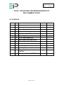
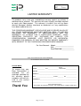
Drawing : - TPC262
Issue
:-8
Date
: - 10/12/13
CD100E
INDUSTRIAL DEHUMIDIFIER
DEHUMIDIFIER
OWNER’S MANUAL
www.eipl.co.uk
Page 1 of 18
Drawing : - TPC262
Issue
:-8
Date
: - 10/12/13
CD100E
PACKAGE CONTENTS
Item
Description
Quantity
1027500
Dehumidifier
1
Wall mounting bracket
1
3081315
M8 X 25 Hex head bolt
10 off
3081505
M8 Flat washer
10 off
3081525
M8 Spring washer
10 off
3088546
Red end cap
6 off
3088552
M8 Spring nut
10 off
3035998
Free socket
1 off
3014338
PVC tube – 12mm I/D
3M
3086101
Jubilee clip
1 off
TPC262
Manual
1 off
Page 2 of 18
Drawing : - TPC262
Issue
:-8
Date
: - 10/12/13
UNPACKING
Carefully remove the CD100 dehumidifier unit from its transit box and visually
check for signs of transit damage. If there is evidence of damage DO NOT
attempt to operate the unit, call your supplier for advice. Do not discard the
packing; it will be useful when transporting the dehumidifier unit in the future.
INTRODUCTION
Dehumidifiers remove moisture from the air that is circulating through the unit.
The resulting reduction of relative humidity helps prevent rust, rot, mould,
mildew and condensation within the room, shelter or other enclosed spaces
where the dehumidifier is used.
A dehumidifier consists of a motor-compressor unit, a refrigerant condenser,
an air circulating fan, a refrigerated evaporator, a means for collecting and
disposing of the condensed moisture and a cabinet to house these
components.
The fan draws the moist room air through the cold evaporator coil which cools
the air below its dew point. Moisture forms on the evaporator and is collected
in the condensate tray then lead away to a permanent drain. The cooled air
then passes through the hot condenser, where it is re-heated with the same
energy removed during the cooling phase and the addition heat derived from
the compressor. The air is therefore discharged into the room at a slightly
higher temperature but at a lower relative humidity than that at which it
entered the unit. Continuous circulation of room air through the dehumidifier
gradually reduces the relative humidity of the room.
The CD100 dehumidifier is a rugged reliable drying unit designed to operate
effectively over a broad range of temperature and humidity conditions. A
powerful and reliable active hot gas defrost system, controlled by an
electronic timer, guarantees positive de-icing, thereby optimizing at low
temperatures.
The unit incorporates a welded steel chassis and is finished in vinyl coated
steel covers for resilience to damage caused by rough handling.
Page 3 of 18
Drawing : - TPC262
Issue
:-8
Date
: - 10/12/13
SPECIFICATIONS
MODEL: CD100E
HEIGHT: 406mm (16”)
WIDTH: 914mm (36”)
DEPTH: 508mm (20”)
WEIGHT: 61 Kg (135 lbs)
AIRFLOW: 1190 M3/hr (700 cfm)
POWER 1090 W (max)
POWER SUPPLY:
110V/120V, 1p,
50Hz/60Hz.
FINISH: Vinyl Coated Steel
Choice of Mobility Aids
MOBILITY: – Wheels of Skid
Handle
REFRIGERANT
R407c (0.54Kg)
TYPE/QTY:
"This product contains fluorinated greenhouse gases covered by the Kyoto Protocol. The
refrigeration system is hermetically sealed.
The Global Warming Potential (GWP) of refrigerants used in products manufactured by Ebac
Industrial Products Ltd is as follows
R134a – 1300
R407c – 1610
For type and weight of refrigerant contained in this unit, please refer to the product data label"
Page 4 of 18
Drawing : - TPC262
Issue
:-8
Date
: - 10/12/13
INSTALLATION
POSITIONING:
Position the dehumidifier unit in the center of the room to be conditioned if at
all possible. However if a damp patch is particularly apparent the outlet grille
should be pointed towards it.
NOTE: Both inlet grille and outlet grille of the dehumidifier unit must have
clear space around them and not be obstructed in anyway.
WIRING:
Connect the power cord of the dehumidifier to a suitable single phase, fused
power supply. As follows:Brown
Live
Blue
Neutral
Green/Yellow
Earth (ground)
ALARM WIRING:
Plug L (Normally Open Contacts)
Plug N (Close on Humidity Rise)
Plug E (Earth)
DRAINAGE:
Connect a 15mm inside diameter hose to the condensate outlet pipe
(positioned centrally, beneath the air inlet grille). Secure the hose using a
worm drive clip. The hose should at no point be raised higher than the outlet
pipe. Failure to observe this requirement will result in flooding of the
dehumidifier unit. Ensure the draintube heater tape is inserted the full length
of the drain tube.
OPTIONAL:
The CD100 may also be fitted with a water pump capable of discharging the
condensate a vertical height of 30ft. The water can, therefore, be discharged
into a drain some distance away.
Page 5 of 18
Drawing : - TPC262
Issue
:-8
Date
: - 10/12/13
OPERATION
The operation of the dehumidifier is to remove moisture from the air by having
it condense on the cool tubes of the evaporator coil. The air then passes over
the hot condenser and returns to the conditioned space slightly warmer and at
reduced moisture content. To concentrate drying all doors and windows
should be kept closed.
AIR MOVING SYSTEM:
Air is drawn in through the inlet grille at the rear of the dehumidifier (below the
handle) and over the two heat exchanges (evaporator/condenser coils) under
the influence of the axial fan, which is driven by the motor. The operation of
the fan motor is to run continuously whenever power is supplied to the
dehumidifier. The fan motor used in the dehumidifier unit is induction
protected i.e. the motor is able to take stalled current without burning out the
motor windings.
TEST FOR CORRECT OPERATION:
WARNING:
DO NOT RUN THE MACHINE WITHOUT THE COVERS IN PLACE FOR ANY
LONGER THAN NECESSARY. DO NOT REMOVE / REPLACE THE
COVERS WITH THE POWER ON
Remove the cover by releasing the retaining bolts and follow the test
procedure laid out below.
1. Set the adjustment humidistat to maximum
2. Switch the machine to the on position; this will result in the compressor
starting to run and the fan blade to starting to rotate.
3. When the compressor has been running for twenty minutes the coils
located above the drain tray will be evenly coated in frost. (If the
temperature is above 25ºC the coils will be covered in water).
4. After the machine has been running for approximately fifty minutes the
unit will automatically enter defrost. The defrost cycle lasts for
approximately three minutes; this will result in the frost on the coils
meeting and dripping into the drainage tray.
5. After the defrost cycle has finished the machine will return to normal
operation.
6. Ensure the condensate drains away from the machine.
Page 6 of 18
Drawing : - TPC262
Issue
:-8
Date
: - 10/12/13
WARNING:
•
•
Due to the high pressures within the refrigeration circuit, under no
circumstances must direct heat be applied to the evaporator coil in an
attempt to remove the build up of ice.
No attempt should be made to cut open any part of the refrigeration circuit
due to high pressures and gas involved. If the unit is switched off at the
mains power supply for any reason, the unit must be allowed to stand at
rest for at least three minutes before restarting. Failure to do so may cause
the unit to blow the fuses owing to the compressor due to there being a
refrigerant imbalance.
SETTING THE ADJUSTABLE HUMIDISTAT:
The positioning of the humidistat depends on the application the CD100 is
being used for and the conditions within the area to be dried. The following
table can be used as a guide:
APPLICATION
HUMIDISTAT
SETTING
FACTORIES
60%
WAREHOUSES
50%
BASEMENTS
50%
DEFLOODING
40%
INDICATOR PANEL
The CD100 is fitted with an indicator lamp to show when power is available
and when the unit is switched on.
If the unit does not appear to be functioning correctly refer to the repairs
section.
Page 7 of 18
Drawing : - TPC262
Issue
:-8
Date
: - 10/12/13
SPECIAL FEATURES
HEATED CONDENSATE DRAINAGE TUBE:
The CD100E dehumidifier is fitted with a heater tape which runs the length of
the condensate tube. The effect of this heated condensate drainage tube will
ensure that the drainage point for the dehumidifier is kept free from ice when
operated in low ambients.
CONTROL AND ALARM HUMIDISTAT:
The CD100E has 2 Humidistats Fitted:
Adjustable Humidistat
This humidistat incorporates a knob / pointer and a graduated scale which
gives the customer the facility to select the desired humidity level within the
room being dried. The humidistat is positioned behind the front cover; this
removes the Humidistat from normal view and therefore reduces the
possibility of being mistakenly adjusted.
Factory Pre-Set Humidistat
The humidistat is factory pre-set at 70%. A Voltage free set of Normally Open
contacts are available at the Alarm Plug situated on the control panel. This
facility allows the customer to connect to an external Alarm Monitoring
System. The contacts will close on High RH.
Page 8 of 18
Drawing : - TPC262
Issue
:-8
Date
: - 10/12/13
ROUTINE MAINTENANCE
WARNING:
ENSURE THAT THE POWER CORD TO THE MACHINE HAS
BEEN DISCONNECTED BEFORE CARRYING OUT ROUTINE
MAINTENACE ON ITEMS 1, 2, 3, 4, AND 5.
To ensure continued full efficiency of the dehumidifier, maintenance
procedures should be performed as follows:
1.
Clean the surface of the evaporator and condenser coils by blowing
the dirt out from behind the fins with compressed air. Hold the
nozzle of the air hose away from the coil (approx 6”) to avoid
damaging the fins. Alternatively, vacuum clean the coils.
WARNING:
DO NOT STEAM CLEAN REFRIGERATION COILS
2.
Check that the fan is firmly secured to the motor shaft and that the
fan rotates freely. The fan motor is sealed for life and therefore
does not need oiling.
3.
To check the refrigerant charge, run the unit for 15 minutes and
briefly remove the cover. The evaporator coil should be evenly frost
coated across its surface. At temperatures above 25°C, the coil
may be covered with droplets of water rather than frost. Partial
frosting accompanied by frosting of the thin capillary tubes,
indicates loss of refrigerant gas or low charge.
4.
Check all wiring connections.
5. To check the operation of the defrost system, switch the machine on
and leave it running for approximately 45 minutes. The machine will
then enter “Hot Gas” defrost mode for approximately 4 minutes
before returning to normal operation. If the unit will not defrost, the
printed circuit timer board may be defective or the by-pass valve may
be inoperable.
IF ANY OF THE PRECEDING PROBLEMS OCCUR, CONTACT THE EBAC
SERVICE CENTER PRIOR TO CONTINUED OPERATION OF THE UNIT TO
PREVENT PERMANENT DAMAGE.
Page 9 of 18
Drawing : - TPC262
Issue
:-8
Date
: - 10/12/13
REPAIRS
1.
Should an electrical component fail, consult the Factory Service
Center to obtain the proper replacement part.
2.
If refrigerant gas is lost from the machine, it will be necessary to use
a refrigeration technician to correct the fault. Contact the Factory
Service Center prior to initiating this action.
Any competent refrigeration technician will be able to service the
equipment. The following procedure must be used:
a. The source of the leak must be determined and corrected.
b. The machine
recharging.
should
be
thoroughly
evacuated
before
c. The unit must be recharged with refrigerant measured
accurately by weight.
d. For evacuation and recharging of the machine, use the crimped
and brazed charging stub attached to the side of the refrigerant
compressor.
The charging stub should be crimped and rebrazed after
servicing. NEVER allow permanent service valves to be fitted to
any part of the circuit. Service valves may leak causing further
loss of refrigerant gas.
3.
The refrigerant compressor fitted to the dehumidifier is a durable
unit that should give many years of service. Compressor failure can
result from the machine losing its refrigerant gas. The compressor
can be replaced by a competent refrigeration technician.
Failure of the compressor can be confirmed by the following
procedure:
a. Establish that power is present at the compressor terminals
using a voltmeter.
b. With the power disconnected, check the continuity of the internal
winding by using meter across the compressor terminals. An
open circuit indicates that the compressor should be replaced.
c. Check that the compressor is not grounded by establishing that
a circuit does not exist between the compressor terminals and
the shell of the compressor.
Page 10 of 18
Drawing : - TPC262
Issue
:-8
Date
: - 10/12/13
TROUBLESHOOTING
SYMPTOM
Unit inoperative
(no red light)
CAUSE
1. No power to unit
REMEDY
1. Check the power supply
and fuse
1. Tighten fan
2. Replace the fan motor
3. See Routine Maintenance
Section
4. Check the wiring diagram
to find fault and repair
1. Check all of the above
2. Contact the Factory
Service Center
3. Contact the Factory
Service Center
4. Contact the Factory
Service Center
1. Contact the Factory
Service Center
2. Contact the Factory
Service Center
Little or no airflow
1. Loose fan on shaft
2. Fan motor burnt out
3. Dirty refrigeration coils
4. Loose electrical wiring
Little or no water
extraction
1. Insufficient air movement
2. Compressor fault
3. Loss of refrigerant gas
4. Blocked filter dryer
Little or no defrost
when required
1. Faulty Timer
2. Faulty bypass timer
Unit vibrates
excessively
1. Loose compressor mounts 1. Tighten the nuts on the
damaged
compressor mounts
2. Damaged Fan
2. Remove obstruction
Spare parts available online
www.EIPLDIRECT.com
Page 11 of 18
Drawing : - TPC262
Issue
:-8
Date
: - 10/12/13
CD100E
SPARE PARTS LIST
Part
Description
Number
1600500
DEFROST TIMER
3014251
3014338
CAPILLIARY TUBE .047 2 pcs.
48” Per
UNREINFORCED PVC TUBE
3020116
COMPRESSOR
3020727
CONDENSER COIL
3020732
EVAPORATOR COIL
3020810
DEFROST VALVE
3020904
FILTER DRYER
3030373
CONTACTOR
3030420
SOLENOID COIL
3030555
ROTARY SWITCH
3031206
PVC 4-CORE MAINS CABLE
3033021
FLOAT SWITCH
3035145
HUMIDISTAT
3035774
MOTOR
3035997
PANEL MOUNTING PLUG
3035998
FREE SOCKET
3036337
RUN CAPACITOR
3036347
PTCR CAPACITOR
3083508
CLAW LATCH
3086101
JUBILEE CLIP
3090611
KNOB
3090612
KNOB CAP BLACK
3090613
KNOB POINTER
3090645
KNOB CAP RED
3940002
AXIAL FAN
Page 12 of 18
Drawing : - TPC262
Issue
:-8
Date
: - 10/12/13
CD100 / CD100E WALL MOUNTING BRACKET KIT
PART NUMBER 1027301
KIT CONTENTS:
Item
Qty
Description
1
2
Frame Hook Rail
2
1
Frame Location Angle
3
1
Frame Top Angle
4
2
Frame Bottom Angle
5
2
‘U’ Channel With Foot
6
2
Frame Support
7
3
3/16” Dome Head Rivet
8
10
M8 X 25mm Hex Head Screw
9
10
M8 Spring Washer
10
10
M8 Flat Washer
11
10
M8 Spring Nut and Plate
12
6
End Cap
13
1
Mounting Fame Assembly
1027301
14
1
Installation Drawing 5060117
Page 13 of 18
Packed
Received
Drawing : - TPC262
Issue
:-8
Date
: - 10/12/13
Assembly Instructions:
With reference to the table above unpack the Mounting Frame Kit and check
for completeness.
With reference to Drawing 1027301 Assemble the mounting frame as follows:1. Using Items 8, 9, 10, 11 assemble Items 4 and 5 ensuring the edge of
the foot is flush with the end of Item 4.
2. Using Items 8, 9, 10, 11 assemble Items 5 and 3 ensuring the distance
of 900mm +/- 2mm is maintained over Items 4.
3. Using Items 8, 9, 10, 11 assemble Items 1, 4 and 6 ensuring the front
edges are flush.
4. Insert Item 12 into the front of the ‘U’ Channel.
5. Drill the appropriate fixing holes into Item 3 to secure bracket onto the
wall.
6. Secure the bracket to the wall
7. With reference to Drawing 5060117 Position the CD100 / CD100E
onto the Wall Mounted Bracket.
8. Using Item 6 assemble items 1 and 2 ensuring the fingers of Item 2
locate into the CD100 chassis.
9. Secure the CD100 / CD100E with the 2 Claw Clamps onto Item 1.
Page 14 of 18
Drawing : - TPC262
Issue
:-8
Date
: - 10/12/13
LIMITED WARRANTY
Our products carry a one-year unconditional warranty against any defects in
workmanship or material. This warranty will cover all parts and labor required
to repair your Ebac product. This warranty is invalid if the unit has been
abused, damaged, whether intentional or accidental, or if any modifications
have been made to the unit.
THE FOREGOING WARRANTY IS EXCLUSIVE AND IS ISSUED IN LIEU OF
ALL OTHER WARRANTIES (WHETHER WRITTEN, ORAL, OR IMPLIED)
INCLUDING THE WARRANTY OF MERCHANTABILITY AND THE
WARRANTY OF FITNESS FOR A PARTICULAR PURPOSE.
EBAC
INDUSTRIAL PRODUCTS, INC. DISCLAIMS ANY LIABILITY FOR
CONSEQUENTIAL DAMAGES, LOST PROFITS, OR INCIDENTAL
DAMAGES FOR BREACH OF ANY WRITTEN OR IMPLIED WARRANTY
WITH RESPECT TO THE FOREGOING DESCRIBED MERCHANDISE.
For Your Records: Model:____________________
S/N:______________________
Date Received:______________
SAVE THIS SECTION FOR YOUR RECORDS
CLIP AND RETURN THIS CARD
PLEASE NOTE
To ensure that your
Ebac Dehumidifier is
accorded
the
full
coverage provided by
this warranty, please
complete and mail this
card at your earliest
convenience.
Thank You
WARRANTY REGISTRATION
DATE
MODEL ___________ S/N ________________ RECEIVED ________________
OWNER __________________________________________________________
ADDRESS ________________________________________________________
CITY __________________________ STATE ________ ZIP _______________
COMMENTS ______________________________________________________
_________________________________________________________________
Ebac Industrial Products.
700 Thimble Shoals Boulevard, Suite 109, Newport News, Virginia. 23606-2575
Page 15 of 18
Drawing : - TPC262
Issue
:-8
Date
: - 10/12/13
Page 16 of 18
Drawing : - TPC262
Issue
:-8
Date
: - 10/12/13
Page 17 of 18
Drawing : - TPC262
Issue
:-8
Date
: - 10/12/13
UK Head Office
Ebac Industrial Products Ltd
St Helens Trading Estate
Bishop Auckland
County Durham
DL14 9AD
American Sales Office
German Sales Office
Ebac Industrial Products Inc Ebac Industrial Products Ltd.
700 Thimble Shoals Blvd.
Gartenfelder Str. 29-37
Suite 109, Newport News
Gebäude 35
Virginia, 23606-2575
D-13599, Berlin
USA
Germany
Tel: +44 (0) 1388 664400
Fax: +44 (0) 1388 662590
Tel: +01 757 873 6800
Fax: +01 757 873 3632
Tel: +49 3043 557241
Fax: +49 3043 557240
www.eipl.co.uk
[email protected]
www.ebacusa.com
[email protected]
www.eip-ltd.de
[email protected]
Page 18 of 18