1
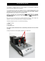
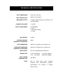
!
JINRO
!
!
INTEGRATED AMPLIFIER
OWNER’S INFORMATION
!
CONTENTS
!
1)
IMPORTANT SAFETY INFORMATION
2)
CE DECLARATION OF CONFORMITY
DISPOSAL
POWER REQUIREMENTS
3)
INTRODUCTION
4)
OVERVIEW
UNPACKING AND INSTALLATION
5) VALVE INSTALLATION
6)
CONNECTION
7)
OPERATION
8)
TECHNICAL SPECIFICATIONS
9)
WARRANTY INFORMATION
10)
CONTACT INFORMATION
! IMPORTANT SAFETY INFORMATION !
RISK OF SHOCK OR ELECTROCUTION! INTERNAL OPERATING
VOLTAGES ARE LETHAL!
Do not remove top cover, unless specifically instructed to do so in the user
manual.
This unit contains fuses and other safety components in accordance with
BS60065 requirements.
In the event of failure, replacement fuse or safety component must be of
the same part type and value.
!
SUCH REPLACEMENT MUST ONLY BE CARRIED OUT BY A
QUALIFIED SERVICE TECHNICIAN.
Do not attempt to replace any fuses without first disconnecting the unit
from the mains electricity supply.
This product must be earthed – ensure that the mains supply cable earth /
ground is correctly connected.
!
This product generates high levels of heat. Adequate ventilation must
be provided. Do not restrict airflow through any ventilation slots or
place the unit on any surface that may restrict airflow.
Valve equipment operates at extremely high temperatures;
KEEP OUT OF THE REACH OF CHILDREN AND ANIMALS.!
Do not store or operate this unit in areas of high humidity or in close
proximity to water / moisture.
Do not expose or immerse the unit in liquid of any kind.
!
OTHER
SAFETY PRECAUTIONS: Never touch the power cord with wet hands.
Always remove the power cord by grasping the plug, not the cable.
Never expose the unit to excessive heat or magnetism.
Never let an inexperienced person repair or reassemble the unit.
Never put anything, especially metal objects, inside the unit.
Never place excessive weight on the unit.
!
CE DECLARATION OF CONFORMITY
We declare under our sole responsibility that this product is in conformity
with the following standards or standardized documents:
BS EN 60065 in accordance with the regulations 73/23/EEC, 89/336/EEC
(from 1 January 1997)
CE 94
Peter Qvortrup,
Director
Audio Note (UK) Limited
25 Montefiore Road
Hove
East Sussex
BN3 1RD
United Kingdom
Tel:
Fax:
+44 (0)1273 220 511
+44 (0)1273 731 498
!
DISPOSAL
This product must not be disposed of as normal household waste. To
prevent possible harm to the environment please separate the product
from other waste to ensure that it can be recycled in an environmentally
safe manner. Please contact your retailer or the appropriate local
government office for collection facilities.
!
POWER REQUIREMENTS
Power requirements for electrical equipment vary depending on your geographical
location. Please ensure that your unit meets the power requirements in your area.
The power requirement for your unit is marked on the serial number plate, located on
the rear panel.
If you are in doubt, please contact your dealer before plugging the unit into the mains
supply.
INTRODUCTION
Thank you for purchasing this Audio Note (UK) product. With the correct care it
should give you many years of pleasure and enjoyment.
Please take the time to read all of the information in this manual before connecting
your new component to an electrical supply or your system, to ensure both your
safety and satisfaction.
Please note that due to our desire to continually improve products, specifications are
subject to change without notice. Therefore it is important to refer to the manual that
is supplied with your product for the most accurate information; manuals downloaded
from our website or obtained from other sources may no longer fully apply to your
product.
If you have any questions regarding the information contained within this document
or your new component, please feel free to contact us: -
Audio Note (UK) Limited
25 Montefiore Road
Hove
East Sussex
BN3 1RD
United Kingdom
Tel:
+44 (0)1273 220 511
Fax:
+44 (0)1273 731 498
e-mail: [email protected]
JINRO INTEGRATED
Congratulations on your purchase of the Audio Note (UK) JINRO Integrated
Amplifier.
It is a Pure Class A Singled Ended valve amplifier that uses the highly regarded 211
triode valve, producing a level of performance that is radically superior to the vast
majority of current designs.
It uses the same circuit design and topology as the legendary Audio Note (UK)
ONGAKU amplifier. However, where the ONGAKU uses silver wherever possible,
such as for all transformer windings, the JINRO instead uses copper.
It has been specifically engineered for sonic performance rather than technical
specification, and fulfills all Audio Note (UK) Level 3 criteria: Pure Class A operation
Zero Negative Feedback
Single Ended Output Stage
Valve Rectification
Directly Heated Triode operation
Materials and component quality
UNPACKING AND INSTALLATION
Please take care when unpacking your JINRO Integrated Amplifier. Choose a clean,
clear location to unpack your unit. Be aware that the amplifier is very heavy; before
attempting to unpack or lift the unit, check the weight and if necessary use more than
one person so that it can be moved safely and easily.
We recommend that you retain and carefully store all of the original packing
materials, in case transportation / shipping is required at a later date.
Select a suitable location for the unit. This should be a dry, dust free and level area,
preferably shielded from direct sunlight and free from vibration. Also ensure that the
location is stable and capable of carrying the weight of the unit.
A suitable mains power outlet must be close to the location; power cords must not be
pulled or stretched tightly in an attempt to reach a wall socket. If the power cord will
not easily reach the socket, choose a closer location!
Please ensure that adequate ventilation for the unit is provided, and that airflow
through any ventilation slots in the unit is not restricted. We recommend a distance of
at least 50cm free space is maintained above the unit, and preferably it should be
sited in free space or on the top shelf of your equipment rack or table. Please also
remember that valve equipment operates at extremely high temperatures, so a
position that is inaccessible to any children or animals is essential.
VALVE INSTALLATION
The amplifier is shipped without the valves installed. It is necessary to install the
valves before the amplifier can be operated.
It is essential that the valves are installed correctly or serious damage that is not
covered by the warranty will result. We recommend that your dealer perform
this procedure for you if you are in any way unsure.
FIRSTLY, ENSURE THAT THE AMPLIFIER IS NOT CONNECTED TO A MAINS
ELECTRICAL SUPPLY, AND THAT THE POWER CORD IS NOT CONNECTED TO
THE AMPLIFIER.
Now remove the 6 valves that are packed inside the amplifier. Also inspect the
amplifier to check that nothing has become damaged during transit.
Carefully unwrap the 6 valves. You will find the following: 1 x ECC82 / 5814a
1 x 7044
2 x 211 valves
2 x 5R4WGB valves
Once again, please understand that it is absolutely vital these valves are fitted
correctly.
Looking from the front of the amplifier, install the 211 valves first: -
VALVE INSTALLATION continued…
Inspect a 211 valve and you will notice that there is a small ‘pin’ protruding from one
side of the valve base; this locating pin ensures that the valve can only be correctly
inserted into the amplifier in one way.
Also examine the two large apertures in the top plate of the amplifier, located
between the two small valves and the black rectangular transformer covers. These
are the insertion points for the 211 valves.
1)
2)
3)
Gently hold a 211 valve, and locate the small side mounted pin on the valve
base.
Line up this pin with the locating hole in the mounting aperture on the
amplifier’s top plate.
Gently insert the valve, and GENTLY twist in a clockwise direction, until the
valve ‘locks’ in position, and no more movement can take place.
Please make sure that steps (1), (2) and (3) are correct. Check again that both
valves are fully inserted correctly in to their respective valve sockets.
VALVE INSTALLATION continued…
Looking from the back of the amplifier, insert the 5R4WGB valves into the two empty
sockets located on the left, situated between the black rectangular transformer
covers and the loudspeaker connection binding posts. Locate the rib on the central
pin of the valve and align with the valve base (it can only be inserted one way due to
this locating rib) and with gentle but firm pressure insert the valve.
Finally, insert the two small signal valves into the front two sockets. Looking from the
front of the amplifier, insert the taller 7044 valve into the left socket, and the smaller
ECC82 into the right socket. The valves can only be inserted one way.
Check one more time that all of the 6 valves are correctly fitted!
CONNECTION
Line inputs
Four line level inputs are available, located on the left side of the
amplifier, at the front of the panel. For sonic purity, it was decided to
not offer any tape / pre outputs on the JINRO. All four inputs are line
level, and can be connected to a suitable line level source of your
choice, such as CD / DAC, phonostage, etc.
Ground Post A ground post is provided for connection to those source components
that also use a separate ground terminal.
Speakers
Each channel is equipped with 2 colour coded binding posts for
connection to your speakers.
Looking from the front of the amplifier, the 2 binding posts to the left
are for the left channel and the 2 binding posts to the right are for the
right channel.
Connect the amplifiers black speaker output binding post to the black /
negative terminal (also marked “ – “) on the speaker.
Connect the amplifiers red speaker output binding post to the red /
positive terminal (also marked “ + “) on the speaker.
Mains
The JINRO is equipped with an IEC 320 mains inlet socket. Use the
supplied mains cable to connect the unit to the local mains supply.
The mains fuses are located in separate fuse holders located on the
rear panel.
Special Note – Make sure that all connections are tight and clean. For
best results use good quality audio interconnects. Although it is
perfectly acceptable to use cables manufactured by other companies,
for best results and performance, we recommend our own Audio Note
(UK) range of interconnects and loudspeaker cables. For further
information, please consult your nearest Audio Note (UK) dealer, or
alternatively please feel free to contact us directly.
OPERATION
Once all the connections are completed and checked, ensure that the volume control
is at the minimum setting (rotated all the way left).
Turn on the amplifier by using the rocker switch located on the rear top right of the
back panel, just above mains inlet socket.
Function Selector
Located on the left of the front panel. Turn the selector to the
source you wish to listen to. The far left position selects the
front pair of RCA / phono sockets; the far right position selects
the rear pair of RCA / phono sockets.
Volume Control
Located on the right of the front panel. This control adjusts the
listening level, or loudness, through 23 precisely chosen steps.
A stepped attenuator was chosen for total sonic purity, as the
delicate signal only passes through two matched resistors of
the highest quality per channel for each volume setting. This is
without question the best and most accurate form of volume
control, and is infinitely superior to any type of conventional
volume attenuator. No remote control is supplied or available;
the sound quality compromises with such devices are too great
for them to be acceptable.
Bedding in
The new amplifier requires about 200 hours of initial use (called
“bedding in”) before the circuitry becomes stable and optimum
performance is realized.
As the amplifier “beds in” the sound will become increasingly
smoother, detailed and open.
Once the amplifier has “bedded in” a warm up time of
approximately 30 to 45 minutes is required each time the
amplifier is switched on before optimum sonic performance is
reached.
Cleaning
No special maintenance is required for the amplifier. Use a
soft, clean lint free cloth to remove any surface marks from the
casework. For finger marks / grease, use a soft, clean lint free
cloth, lightly moistened with a solution of warm water and mild
detergent. Do not use any alcohol or solvent based cleaning
products, as they may damage the finish of the amplifier.
ENSURE THAT THE AMPLIFIER IS SWITCHED OFF AND
DISCONNECTED FROM THE MAINS ELECTRICITY
SUPPLY BEFORE UNDERTAKING ANY CLEANING.
Valve Life
The valves supplied with your amplifier should provide
approximately 6000 hours of operation. They are specially
selected by us, and should only be replaced with matched
pairs. Please consult your Audio Note (UK) dealer should your
valves need replacing.
TECHNICAL SPECIFICATIONS
INPUT IMPEDANCE
100k ohm, line level
INPUT SENSITIVITY
450mV for full output
MAXIMUM OUTPUT
20 watts (approximate) per channel into 4
or 8 Ohm loads
CHANNEL BALANCE
+/- 0.3dB
VALVE COMPLIMENT
2 x 5R4WGB
2 x 211
1 x ECC82 / 5814a
1 x 7044
UNIT WEIGHT
27.5KG
SHIPPING WEIGHT
(ORIGINAL PACKAGING)
40KG
UNIT DIMENSIONS
305mm (h) x 305mm (w) x 640mm (d)
SHIPPING DIMENSIONS
(ORIGINAL PACKAGING)
420mm (h) x 420mm (w) x 760mm (d)
MAINS INPUT
AC 100-120V/220-240V 50/60 Hz
MAINS FUSE
3.15A Anti Surge
1.2A Anti Surge
MAX. POWER
CONSUMPTION
NOTE
(110/120V Supply)
(200/240V Supply)
200 Watts
Due
!
to
research
Audio
and
specifications
without notice.
!
Note
(UK)’s
development
are
subject
ongoing
program,
to
change
WARRANTY INFORMATION
Audio Note (UK) warrants this product to be free from defects in materials and
workmanship for two years from the original date of purchase from an appointed
Audio Note (UK) dealer, and agrees to covers the cost of parts and associated labour
required to correct such defects, subject to terms & conditions.
This Warranty is offered to the first purchaser only.
Any valves supplied with the unit are warranted for three months from the original
date of purchase.
If the product fails in normal domestic use and during the Warranty period due to the
above described faults or defects, Audio Note (UK) will, at its discretion, repair or
replace the item free of charge within a reasonable time once it has been returned to
Audio Note (UK) or an appointed Audio Note (UK) dealer or service engineer.
Audio Note (UK) is not liable for any shipping charges incurred whilst transporting the
product to or from Audio Note (UK) or an appointed Audio Note (UK) dealer or
service engineer, should the item require service or repair during or after the
Warranty period.
If the product must be shipped, please use the original packaging materials and
include a copy of the original sales receipt along with a note explaining, in as much
detail as possible, the problems you are experiencing with the unit.
Only use a reputable Courier Service or Shipping Agent, and ensure that your
product is insured during transit.
Any servicing, repairs or modifications not authorized by Audio Note (UK), or
carried out by persons other than appointed Audio Note (UK) service
engineers will invalidate any warranty.
This Warranty does NOT cover: Damage sustained whilst in the possession of a shipping agent, retailer or consumer
and not caused as a direct result of defects in materials or workmanship.
Damage caused by normal wear and tear.
Damage or defects caused by abnormal or unreasonable use.
Damage caused by accident, acts of nature, misuse or neglect.
Damage caused by a failure to follow the operating and installation instructions
supplied with the product.
Damage caused by improper or careless cleaning.
Audio Note (UK) reserves the right to refuse warranty for any component of which
the serial number has been removed, defaced or tampered with.
CONTACT INFORMATION
If in the future your Audio Note (UK) product
requires servicing, or if you require technical support
or have any questions regarding this or any of our
other products, please contact your local Audio Note
(UK) dealer.
Alternatively, please feel free to contact us directly: -!
Audio Note (UK) Limited
25 Montefiore Road
Hove
East Sussex
BN3 1RD
United Kingdom
Tel:
+44 (0)1273 220 511
Fax:
+44 (0)1273 731 498
e-mail: [email protected]