1
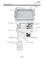
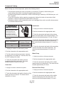
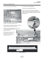
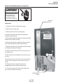
Service Manual for
Cuber Model CS0415
CS0415
Service Manual
Introduction
This is the service manual for the CS0415 ice
machine.
Note and heed any warning symbols where they
appear.
Basic installation information is provided, however
the installation manual is separate.
Table of Contents
Specifications . . . . . . . . . . . . . . . . . . . . . . . . . . . . . . . . . . . . . . . . . . Page 3
Installation: . . . . . . . . . . . . . . . . . . . . . . . . . . . . . . . . . . . . . . . . . . . Page 4
Test Mode - Ice Thickness Adjustment . . . . . . . . . . . . . . . . . . . . . . . . . . . . . Page 5
Technical Charts: . . . . . . . . . . . . . . . . . . . . . . . . . . . . . . . . . . . . . . . . Page 6
Operational Modes: . . . . . . . . . . . . . . . . . . . . . . . . . . . . . . . . . . . . . . . Page 7
Harvest Mode . . . . . . . . . . . . . . . . . . . . . . . . . . . . . . . . . . . . . . . . . . Page 8
Component Location . . . . . . . . . . . . . . . . . . . . . . . . . . . . . . . . . . . . . . Page 9
Component Location . . . . . . . . . . . . . . . . . . . . . . . . . . . . . . . . . . . . . . Page 10
Diagnostic Mode
. . . . . . . . . . . . . . . . . . . . . . . . . . . . . . . . . . . . . . . . Page 11
Error Displays . . . . . . . . . . . . . . . . . . . . . . . . . . . . . . . . . . . . . . . . . . Page 12
Component Testing . . . . . . . . . . . . . . . . . . . . . . . . . . . . . . . . . . . . . . . Page 13
Component Testing . . . . . . . . . . . . . . . . . . . . . . . . . . . . . . . . . . . . . . . Page 14
Flow Chart - Overall Operation . . . . . . . . . . . . . . . . . . . . . . . . . . . . . . . . . Page 15
Flow Chart - Freeze Mode Details
. . . . . . . . . . . . . . . . . . . . . . . . . . . . . . . Page 16
Service Diagnosis . . . . . . . . . . . . . . . . . . . . . . . . . . . . . . . . . . . . . . . . Page 17
Service Diagnosis . . . . . . . . . . . . . . . . . . . . . . . . . . . . . . . . . . . . . . . . Page 18
Removal and Replacement - Thermistor . . . . . . . . . . . . . . . . . . . . . . . . . . . . Page 19
Removal and Replacement . . . . . . . . . . . . . . . . . . . . . . . . . . . . . . . . . . . Page 20
Removal and Replacement - Controller . . . . . . . . . . . . . . . . . . . . . . . . . . . . . Page 21
Removal and Replacement . . . . . . . . . . . . . . . . . . . . . . . . . . . . . . . . . . . Page 22
Removal and Replacement - Evaporator . . . . . . . . . . . . . . . . . . . . . . . . . . . . Page 23
July 2007
Page 2
CS0415
Service Manual
Specifications
Scotsman Ice Systems are designed and
manufactured with the highest regard for safety
and performance. They meet or exceed the
standards of agencies like NSF and UL..
Storage Capacity (Approximate)
• 24 lbs. (10.9 kg)
Exterior Dimensions (W x D x H)
Scotsman assumes no liability or responsibility of
any kind for products manufactured by Scotsman
• 15" x 24" x 34" (381 or 457.2 x 609.6 x 863.6
hat have been altered in any way, including the use
mm)
of any part and/or other components not
specifically approved by Scotsman.
Exterior Finish:
Scotsman reserves the right to make design
changes and/or improvements at any time.
Specifications and design are subject to change
without notice.
AC Power Supply:
• 104 to 127 VAC (rated 115 VAC), 60 Hz
Amperage:
• 6.5 Amps (max)
Minimum Circuit Capacity:
• Painted Steel
Net Weight:
• 94 lb. (42.6 kg)
Cube Thickness Control:
• Thermistor under Evaporator & Control
Board Setting
Harvest Control:
• Thermistor under Evaporator & Control
Board Setting
• 15 Amps
Ice Production per 24 hours (Approximate)
•
•
•
•
70oF (27oC) 46 lbs (21 kg)
80oF (27oC) 47 lbs (21 kg)
90oF (32oC) 40 lbs (18 kg)
100oF (38oC) 40 lbs (18 kg)
Ice Shape:
• 3/4" x 3/4" Square
Ice Thickness @ Normal Setting (Approximate)
• 0.32" or 5/16" (8.1 mm)
Ice Thickness @ Thin Setting (Approximate)
• 0.28" or 9/32" (7.0 mm)
Bin Ice Level Control:
• Thermistor on side of Bin
Refrigerant:
• R-134a (6.2 oz). Weigh into high side only.
Ambient Temperature Operation Range:
• 55 to 100oF
Water Pressure Operating Range
• 20 to 120 psig
Water Consumption (Dependent On Water
Pressure)
• 6 to 10 gallons per 4 hours
Ice Thickness @ Thick Setting (Approximate)
• 0.39" or 3/8" (9.9 mm)
July 2007
Page 3
CS0415
Service Manual
Installation:
The ice machine is designed to be installed
indoors, in a controlled environment. Do not place
where the temperature limits for air or water are
exceeded.
The water supply must be cold, potable water. A
drain must be nearby or a drain pump model used
or a gravity drain model must be converted to use a
drain pump.
The ice machine must be on its own electrical
power circuit. The machine must be grounded. Do
not connect to an extension cord. Do not cut off the
ground prong off the power cord plug. Do not
bypass the ground prong.
The cabinet is designed to be either free standing
or built in. In either case the area in front of the
kickplate must be free of obstruction. Blocking this
area will cause low ice capacity and likely damage
the machine. Such damage is considered mis-use
and is not covered by warranty.
When building into a cabinet, be sure the power
supply, water and drain are all available within the
built in area.
Drain Hose*
Vent Hose*
Water Inlet
Back View
* Drain Pump Models
July 2007
Page 4
CS0415
Service Manual
Test Mode - Ice Thickness Adjustment
The CS0415 has three push button switches: ON,
OFF and CLEAN. These can be used to switch the
machine on, off and to start the cleaning process.
They can also be used to test the unit's
components.
Test 9, no component tested.
To test and/or to adjust ice thickness:
The Off light is the indicator.
Test 10, displaying the ice thickness setting.
Ice Thickness Adjustment.
• If it blinks 2 times and repeats, the ice
1. Unplug or disconnect the unit from the power
supply.
thickness is set at thin.
• If it blinks 4 times and repeats, the ice
thickness is set at normal.
Note: Unit must be On (make ice mode) when
power is disconnected.
• If it blinks 6 times and repeats, the ice
thickness is set at thick.
2. Reconnect power to the unit.
3. Immediately, within ten seconds of power
re-connection, push and hold the On and Clean
buttons until the three indicator lights begin to blink.
Pushing and releasing the Clean button between
flashes adjusts the thickness setting to the next
one.
4. Push and release the On button to cycle through
testing the various components.
Note: 10 push-and-releases will switch the
controller to ice thickness adjustment mode.
Pre-Test Mode: All 3 lights are on steady.
Test 1, testing the bin thermistor. The On light is
the indicator, if it is on steady, it is OK. If it blinks
twice and repeats, it is open. If it blinks 4 times and
repeats, it is shorted.
Test 2, testing the evaporator thermistor. The
Clean light is the indicator, if it is on steady, it is
OK. If it blinks twice and repeats, it is open. If it
blinks 4 times and repeats, it is shorted.
Test 3, testing the inlet water valve. Four minute
test.
Test 4, testing the water level sensor.
Test 5, testing the water pump.
Test 6, Testing the reservoir drain pump.
Test 7, testing the compressor and condenser fan
motor.
Test 8, testing the compressor and hot gas valve.
July 2007
Page 5
CS0415
Service Manual
Technical Charts:
Bin Thermistor
Cut-In
Temperature
Bin
o
Cut-Out
Resistance
o
40 F. +/- 1 F.
Temperature
25.9k ohms +/- 3 %
o
Resistance
o
35 F +/- 1 F.
29.8 ohms +/- 3 %
Evaporator Thermistor
End Harvest Readings
Ice Thickness
Temperature
Resistance
52oF. +/- 3%
18.7k ohms +/-1%
Wattage @ 120 V
Resistance
Normal
Thick
Thin
Other Technical Information
Compressor
244
Run
1-5
Start
3 - 11
Water pump
7.5
3.6
Reservoir drain pump
4.5
3.6
Water valve
20
Hot gas valve
7-9
385
Bin thermistor
10k @ 77oF.
Evap thermistor
10k @ 77oF.
Transformer
73
Fan motor
5.1 - 7.1
185
Cutter grid
20
July 2007
Page 6
CS0415
Service Manual
Operational Modes:
There are four main operational modes for the ice
maker:
•
•
•
•
Freeze
Harvest
Clean
Service (Diagnostics)
Ice Making Cycle
In addition, there are three possible “Off” cycles for
the ice maker. They occur when:
1. The bin is full of ice and the LED is illuminated
“ON/OFF” (Idle mode).
2. The “On/OFF” control switch has been held for
three seconds. The ON/OFF LED will go out.
During the Freeze mode, some of the hot gas that
is in the condenser accumulating tube, condenses
to a liquid, and remains in the accumulating tube.
During the later stages of the Freeze mode, as the
ice slab forms on the evaporator freezing plate,
some of the refrigerant passing through the
evaporator will not evaporate into a gas, but will
remain a liquid. This liquid refrigerant will settle in
the accumulator, while the refrigerant vapor is
sucked off through the suction tube at the top of the
accumulator. This accumulated liquid refrigerant
will eventually be directed to the evaporator to
quickly warm the evaporator plate during the
Harvest mode.
Note: It is very important that the accumulator is
not tilted out of a horizontal position. If moved, it
could cause compressor failure.
Electrical System
Water System
Line Voltage is supplied to the electrical control
switches and the primary side of the step-down
dual transformer. The dual transformer reduces
120 VAC to 8.75 VAC for the cutter grid and the
bin light and 12 VAC for the drain and
recirculating pumps. The electronic control board
directs 12 VAC to the water recirculating and
reservoir drain pumps, and 120 VAC to the hot gas
solenoid, condenser fan motor, and compressor.
The measured fill water valve will always have 120
VAC on the BK and WH wires and 14 VDC on the
OR/WH and BK/RD wires.
An evaporator thermistor supplies temperature
information to the electronic control to determine
when to terminate the harvest cycle.
Refrigeration System
The hot gas refrigerant, under high pressure, is
forced through the condenser, where it changes
into a liquid, and flows through the drier and
capillary tube into the evaporator. Under low
pressure in the evaporator, the liquid refrigerant
absorbs heat from the water flowing over the
evaporator as the refrigerant evaporates into a gas.
As a low pressure gas, the refrigerant flows back
through the suction line of the heat exchanger, to
the compressor.
The water recirculating pump moves the water from
the reservoir pan up to the distributor, where it
flows out over the evaporator freezing plate.
Water that does not freeze on the evaporator plate
runs off the front edge, and falls back into the
reservoir, where it is recirculated back to the water
distributor.
As the ice slab forms, the minerals in the water are
on the surface of the ice. The water flowing over
the top of the ice slab washes these minerals back
into the water reservoir pan. The water continues to
recirculate until the water level in the reservoir
drops to the bottom of the water level sensor.
When the water level in the reservoir drops below
the sensor, the control terminates the freeze mode
and initiates the harvest mode.
The control signals the measured fill valve to fill to
the selected water level setting. The measured fill
valve uses a flow meter to accurately fill to the
correct volume.
• Thin Ice uses 32 ounces (954cc),
• Normal Ice 37 ounces (1106cc), and
• Thick Ice 42.5 ounces (1258cc).
July 2007
Page 7
CS0415
Service Manual
Harvest Mode
Electrical System
When the water level in the reservoir drops below
the water level sensor it signals the electronic
control to terminate power to the condenser fan,
and then the water recirculating pump. The
reservoir drain pump is activated to fully drain the
reservoir. Power is then supplied to the hot gas
valve and a fill request is sent to the measured fill
valve. The fill valve fills to the requested volume
while the hot gas valve is energized for the balance
of the harvest mode.
If the evaporator thermistor is unplugged, the
evaporator defaults to a timed 4 minute harvest.
If the water level sensor is disconnected or open,
the control defaults to 25 minutes of freeze time.
The cleaning indicator LED feature will not function
if the water level sensor is disconnected.
The electronic control board operates the various
components and systems in the ice maker for each
of the Freeze and Harvest modes.
Clean Mode
Electrical System
The electronic control board operates the various
components and systems during the Clean mode.
Water System
When the service control switch is in the “Clean”
position, the water pump circulates the cleaning
solution that has been added to the reservoir, up to
the water distributor, across the evaporator, and
back into the reservoir, where it is recirculated. The
compressor and hot gas valve operate to heat the
evaporator.
Refrigeration System
The hot gas valve opens, allowing high pressure
refrigerant gas to bypass the condenser, and flow
through the condenser accumulating tube. The hot
gas pushes the liquid refrigerant that has
accumulated in the accumulator tube up into the
evaporator. The hot liquid refrigerant evenly heats
the evaporator plate so that the ice slab releases
quickly and evenly.
The ice slab, when released, slides off of the
evaporator plate onto the cutter grid.
Water System
The electronic control board sends a signal to the
water valve. The signal tells the water valve how
much water to be filled, allowing water to flow into
the water reservoir pan. The water fill volume is
determined by the ice thickness setting.
As a result of the hot gas flow and the ice sliding off
the evaporator plate, the evaporator temperature
begins to rise. When the evaporator thermistor
reaches the set temperature (52°F), the unit
switches to the Freeze mode. This cycling between
Freeze and Harvest, continues until the ice bin is
full.
July 2007
Page 8
CS0415
Service Manual
Component Location
Light Switch
Controller
Transformer
Push Button Switches
Evaporator
Cutter Grid
Bin
Thermistor
Water Level Sensor
Water Pump
Compressor
Reservoir Drain
Pump
Fan Motor
Hot Gas Valve
Condenser
Measured Fill Inlet
Water Solenoid Valve
Condenser Accumulator Tube
July 2007
Page 9
CS0415
Service Manual
Component Location
Water
Distributor
Evaporator
Water Return
Tube
Water Level
Sensor
Water Pump
Manual Drain
Resevoir
Reservoir
Drain Pump
Water Valve
Outlet Tube
Measured Fill
Valve
Bin
Drain
July 2007
Page 10
CS0415
Service Manual
Diagnostic Mode
Do not continue with the diagnosis of the ice maker if a fuse is blown, a circuit breaker is tripped, or if
there is less than a 120 volt power supply at the wall outlet. Units that failed during the first few days of
use should be checked for loose connections or miswiring.
Entering and Navigating — Manual Diagnostics
Turn the product to On. Within 10 seconds of Power On, press and hold the On and the Clean buttons.
Release both buttons when all user interface LEDs begin to flash.
Within 5 seconds of all LEDs flashing, push any other button (On, Off, or Clean). This begins manual
diagnostics. If no button is pressed within 5 seconds, the product goes into an automatic diagnostic
mode. Each component is cycled for 5 seconds.
The Off button is used to advance through each step. To exit manual diagnostics, press the On button .
After pressing any button to enter manual diagnostics all LEDs will illuminate for 5 seconds. The controls
will then automatically move to the first component.
Order
Component
On LED
Off LED
Clean LED
1
Entry into Test Mode
ON
ON
ON
2
Bin Thermistor
ON Solid—OK. 2
blinks—Open. 4
blinks—Shorted.
OFF
OFF
3
Evaporator Thermistor
OFF
OFF
ON Solid—OK
2blinks—Open
4blinks—Short
4a
Water Valve 4 min time
out Off button press will
advance to step 6
OFF
ON Solid—reservoir full
Blinking—reservoir empty
ON
4b
Water Level Sensor
OFF
ON Solid—reservoir full
Blinking—reservoir empty
ON
5
Water Pump
ON
ON
ON
6
Reservoir Drain Pump
ON
OFF
OFF
7
Compressor and
Condenser Fan Motor
ON Solid while
cooling
Blinking when evap
thermistor reaches 4.5ºF;
full frost pattern should be
visible
ON
8
Compressor and Hot
Gas Valve
ON Solid while
heating
ON Solid while heating
Blinking when evap
thermistor reaches 52ºF
ON Solid while
heating
9
None
Off
Off
On is normal*
OFF
2 Blinks—Thin. 4 Blinks
—Normal. 6 Blinks —Thick.
Press Clean button to cycle
between settings
OFF
10
Ice Thickness
July 2007
Page 11
CS0415
Service Manual
Error Displays
These errors will occur at any time during normal operation if a thermistor fails.
• 2 Blinks - Off Light is blinking twice in repeating intervals – This signals a bin thermistor failure.
Check that the bin thermistor is plugged in to the control box. Check that the bin thermistor is not
open or shorted. Replace the thermistor if it is open or shorted.
• 3 Blinks- Off Light is blinking three times in repeating intervals – This signals a harvest failure.
Check that the evaporator thermistor is connected to the sealed system tubing. If the thermistor is
plugged in, ensure that it is fully connected to the control box. (The ice maker will operate on a
timed cycle if the evaporator thermistor is unplugged.) Check the resistance of the thermistor. If
the thermistor checks good, then look for a frost pattern on the evaporator plate. The unit may be
low on refrigerant.
Note: The lights will continue to blink after correction until the unit is shut off and then switched back on.
The power cord on the internal drain pump is connected to a 120 VAC wall outlet. The ice maker is then
connected to the 120 VAC outlet on the drain pump. If the drain pump fails, or if the drain becomes
blocked, power is shut off to the 120 VAC outlet on the drain pump.
When the unit is first plugged in, the drain pump will run for 20 seconds. The power can be
disconnected and reconnected to verify that the pump is operating properly.
Water from the ice maker reservoir, or melting ice from the bin, drains down the bin drain tube into the
pump inlet, and then into the drain pump chamber. As the water level rises, it bridges the “full” contacts,
and the pump starts to run. The pump discharges the water through the outlet and the check valve.
When the “full” connection is removed, the pump runs for an additional 12 seconds to empty the tank.
If the water level in the drain pump continues to rise, due to a slow or blocked drain, or a blocked vent
hose, and touches the “overfill" contact, power will be turned off to the drain pump’s 120 VAC outlet,
causing the ice maker to turn off.
July 2007
Page 12
CS0415
Service Manual
Component Testing
Before testing any of the components, perform the following checks:
• Control failure can be the result of corrosion on connectors. Therefore, disconnecting and
reconnecting wires will be necessary throughout test procedures.
• All tests/checks should be made with a VOM or DVM having a sensitivity of 20,000 ohms per- volt
DC, or greater.
• Check all connections before replacing components, looking for broken or loose wires, failed
terminals, or wires not pressed into connectors far enough.
• Resistance checks must be made with power cord unplugged from outlet, and with wiring harness
or connectors disconnected.
Transformer
1. Unplug ice maker or disconnect power.
Electrical Shock Hazard
Electrical shock can
cause personal injury.
Disconnect electrical
power before proceeding.
2. Set the ohmmeter to the appropriate scale.
3. Touch the ohmmeter test leads to the primary
black and white leads of the dual transformer. The
meter should indicate between 3.5 and 4.5 ohms.
Thermistor
Sensor Temperature °F
Resistance Range W
32
29,000 to 31,000
75
9,500 to 10,500
4. Touch the ohmmeter test leads to the secondary
yellow and yellow leads of the dual transformer.
The meter should indicate between 0.11 and 0.14
ohms.
5. Touch the ohmmeter test leads to the secondary
red and red leads of the dual transformer. The
meter should indicate between 0.14 and 0.18
ohms.
1. Unplug ice maker or disconnect power.
2. Set the ohmmeter to the appropriate scale.
3. For the most accurate measurement, immerse
the thermistor in ice water for 5 minutes, then use
the 32°F reading in the chart.
Water Pump
4. Touch the ohmmeter test leads to the two
evaporator thermistor connectors. The meter
should indicate as shown in the chart.
2. Set the ohmmeter to the appropriate scale.
1. Unplug ice maker or disconnect power.
3. Touch the ohmmeter test leads to the outside
water pump wire connector pins. The meter should
indicate approximately 3.6 ohms.
Cutter Grid
1. Unplug ice maker or disconnect power.
Reservoir Drain Pump
2. Set the ohmmeter to the appropriate scale.
1. Unplug ice maker or disconnect power.
3. Touch the ohmmeter test leads to the pins of the
cutter grid 2-wire connector. The meter should
indicate 4 to 5 ohms
2. Set the ohmmeter to the appropriate scale.
3. Touch the ohmmeter test leads to the outside
reservoir drain pump wire connector pins. The
meter should indicate approximately 3.6 ohms.
July 2007
Page 13
CS0415
Service Manual
Component Testing
d) Turn the relay over so that the coil faces up, as
shown below.
Water Level Sensor
1. Run the diagnostic tests and check for the
proper operation of the water level sensor in step
4b.
e) With the tip of the ohmmeter test leads at the
Start (S) and Run (M) pin sockets, the meter
should indicate a closed circuit (0 ohms).
2. With the water level sensor immersed in water
the Service LED should stay on solid.
3. With the water level sensor out of the water the
Service LED should blink.
Measured Water Fill Valve
Electrical Shock Hazard
Electrical shock can
cause personal injury.
Disconnect electrical
power before proceeding.
1. Unplug ice maker or disconnect power.
2. Unsnap and remove the cover from the
measured fill water valve.
3. Set the ohmmeter to the appropriate scale.
4. Touch the ohmmeter test leads to the measured
fill water valve solenoid terminals. The meter
should indicate between 240 and 280 ohms.
Compressor Start Relay
Position the relay with the coil facing down, as
shown below.
b) Insert the tip on one of the ohmmeter test leads
into the Run (M) pin socket, and touch the other
ohmmeter lead to the spade terminal. The meter
should indicate a closed circuit (0 ohms).
c) Move the tip of the ohmmeter test lead from the
spade terminal into the Start (S) pin socket. Leave
the other ohmmeter lead at the Run (M) location.
The meter should indicate an open circuit (infinite).
July 2007
Page 14
CS0415
Service Manual
Flow Chart - Overall Operation
Switch On
Flush Mode
Begins
Water Level
Drops Below
Sensor?
25 min. of
freeze time?
No
Yes
Freeze Mode
Begins
Harvest Mode
Begins, water
drains and refills
Yes
Compressor and
Hot Gas Valve on
for 1 minute
Yes
Bin Full?
No
Compressor and
Hot Gas Valve on
for 1 minute
Evaporator
more than
52oF.?
No
Compressor and
Hot Gas Valve on
for 3 minutes.
No
Evaporator
more than
52oF.?
Yes
Idle Mode
Yes
Yes
Evap
Thermistor
Unplugged?
Yes
Freeze Mode
No
Yes
Evaporator
more than
52oF.?
Yes
Yes
No
Continued Harvest
Mode
16 minutes
max harvest
time?
Bin Full?
Yes
Yes
Failure Mode
No
No
Evaporator
more than
52oF.?
No
July 2007
Page 15
CS0415
Service Manual
Flow Chart - Freeze Mode Details
Freeze Mode
Water Level
Sensor
Detected?
Yes
No
Comp., fan motor,
spray pump are on
Comp., fan motor,
spray pump are on
for 25 minutes
maximum
No
5 minutes up?
Yes
Water level
drops below
sensor?
Yes
Hung Slab Noted
No
Comp., fan motor,
spray pump are on
Water level
drops below
sensor?
Yes
No
No
20 minutes up?
Yes
Harvest Mode
July 2007
Page 16
CS0415
Service Manual
Service Diagnosis
Symptom
No ice, not operating
No ice. Will not make ice. Water
reservoir is empty. Evaporator is
cold with thin or no ice slab.
Will not make ice. Water
reservoir is empty. Evaporator is
cold with 3/4" thick or larger ice
slab
Off LED on.
Possible Cause
Probable Correction
No power at wall outlet
Check circuit breaker/fuses
No power at auxiliary drain
pump power outlet
Check for kinked drain hose,
blocked screen or blocked vent
outlet or hose.
Disconnected selector switch
Reconnect and check for proper
operation.
Room temperature below 55oF.
(13oC)
Bin thermistor has unit shut off
Ice touching bin thermistor
Normal operation
Water supply turned off
Turn on water supply
Loose or missing reservoir cap
Tighten or replace
Water slide return tube out of
reservoir
Reposition tube
Inlet tube out of position and
missing reservoir
Reposition tube
Water inlet tube frozen near
evaporator
Thaw and reposition tube
Defective inlet water valve
Test and repair or replace
An ice slab only partially
released from evaporator and
water was bridged down into the
bin
Look for interference with cutter
grid and clean the evaporator
plate
Slab will not release during
harvest due to scale build up
Clean the evaporator plate
Defective or disconnected hot
gas valve
Test and repair or replace
Room temperature over 100oF
(38oC)
Move machine or reduce heat
Open or disconnected bin or
evaporator thermistor or
thermistor wiring
Test thermistor & wiring harness
or reconnect
July 2007
Page 17
CS0415
Service Manual
Service Diagnosis
Symptom
Will not make ice. Water
reservoir is full. Evaporator is
cold with thin/partial/irregular or
no ice slab
Possible Cause
Probable Correction
Seeping water valve. Condenser
is hot
Replace water valve
Partial refrigerant leak or
restriction (U-shaped slab)
Check for leak/restriction and
repair or replace defective
component
Defective recirculating pump
Repair or replace the pump
motor assembly
Partially blocked water distributor Clean distributor and evaporator
Test compressor, relay and
overload
Compressor is not running
Will not make ice. Water
reservoir is full. Evaporator is
warm.
Blocked condenser or stalled fan Clean condenser, repair or
motor
replace motor
Unit is in the startup mode
Wait 5 minutes and recheck
o
Low capacity
Too much ice in bin
Room temperature below 55 F
(13oC)
Bin thermistor has unit shut off.
Advise user.
Seeping water valve. Condenser
is hot
Replace water valve
Slow or defective drain or drain
pump causing water to back up
into the bin
Repair or replace drain or drain
pump
Airflow blocked
Remove blockage
Control in extended cycle mode
Go to manual test 9, if clean light
is blinking, push Clean button
once.
Defective bin thermistor
Test and replace thermistor
Banging sound
Noise
Ice freezing together in the bin
Grinding, cavitating sound.
The slab dropping off the plate
and ice dropping from the cutter
grid into an empty bin are normal
sounds
The reservoir is empty. Look for
a partially released slab,
interference with cutter grid etc
and clean the evaporator plate.
Grinding, cavitating sound from
recirculating pump
If the reservoir is full replace the
pump
Noisy drain pump
Repair or replace
Normal if little ice is used.
Use more ice.
July 2007
Page 18
CS0415
Service Manual
Removal and Replacement - Thermistor
Slide the cutter grid forward and out of the unit and
place it on a work surface.
Be careful not to scratch the ice maker liner.
Electrical Shock Hazard
Electrical shock can
cause personal injury.
Disconnect electrical
power before proceeding.
d) Remove the spacer from the right cutter grid
bracket tab.
Unsnap the two ice guides from the cutter grid
tabs. There should be a slight outward tilt after the
guides are installed. Bend the metal tabs outward if
necessary.
Bin Thermistor and / Or Cutter Grid
1. Unplug ice maker or disconnect power.
Control Housing
2. Open the ice maker door.
3. Cover or remove the ice from the storage bin.
4. Place a cloth in the drain hole to avoid hardware
from falling inside.
5. Remove the two hex-head screws from the
cutter grid cover and remove the cover.
Bin Thermostat
Connector
Cutter Grid
6. To remove the bin thermistor:
a) Disconnect the bin thermistor connector from the
bottom of the control housing.
b) Pull the bin thermistor out of the retaining clamp
and remove it.
7. To remove the cutter grid:
a) Disconnect the cutter grid and bin thermistor
connectors from the bottom of the control housing.
b) Remove the two hex-head screws from both
sides of the cutter grid. The longer screw and white
spacer are on the right side.
July 2007
Page 19
Cutter Grid
Connector
Cutter Grid
Screws
CS0415
Service Manual
Removal and Replacement
To remove the evaporator thermistor:
To remove the water distributor:
a) Remove the cutter grid from the unit
b) Pull out on the left and right water distributor
retainers, and remove the tabs from the slots in the
evaporator. Pull the distributor forward and remove
the water hose.
Evaporator
Thermistor
a) Remove the cutter grid from the unit
b) Disconnect the evaporator thermistor connector
from the bottom of the control housing.
Tab
c) Remove the two hex-head mounting screws
from the water trough and pull the
trough from the unit.
Reach behind the accumulator,
and unclip the evaporator
thermistor from the evaporator
tubing and remove it.
Water Hose
Water Distributor
July 2007
Page 20
CS0415
Service Manual
Removal and Replacement - Controller
7. To remove the electronic control board:
a) Disconnect the six harness connectors from the
board terminals.
Electrical Shock Hazard
Electrical shock can
cause personal injury.
Disconnect electrical
power before proceeding.
b) Remove the two mounting screws.
Screw
1. Unplug ice maker or disconnect power.
2. Open the ice maker door.
3. Cover or remove the ice from the storage bin.
4. Remove the cutter grid cover and the cutter grid.
Water Pump
5. Disconnect the remaining two connectors (bin
and evaporator thermistors) from the bottom of the
control housing.
Unplug ice maker or disconnect power.
2. Open the ice maker door.
3. Remove the ice from the storage bin.
4. Unscrew the drain cap from the reservoir, drain
the water, and replace the cap tightly.
5. Place a cloth in the drain hole to avoid hardware
from falling inside.
6. Remove the hex-head screw from the water
recirculation pump shield and remove the shield
(see the photo below).
6. Remove the four hex-head screws from the
control housing and lower the housing so that you
can access the components.
NOTE: The control housing components consist of:
Water Reservoir
• (1) Electronic control board
Drain Cap
• (2) Dual transformer
Reservoir
Drain Pump
• (3) Light switch
• (4) Push-button switch assembly
July 2007
Page 21
CS0415
Service Manual
Removal and Replacement
3. Unscrew the drain cap from the reservoir, drain
the water, and replace the cap tightly.
Electrical Shock Hazard
Electrical shock can
cause personal injury.
Disconnect electrical
power before proceeding.
4. Remove the recirculating pump cover hexhead
screw.
5. To remove reservoir drain pump:
a) Disconnect the reservoir drain pump electrical
connection.
7. Disconnect the water fill tube from the pump
mounting bracket.
b) Remove the pump retaining screw and bracket.
8. Disconnect the two wire pump connectors from
the harness block.
c) Rotate the pump 1/4 turn and pull it down and
out of reservoir.
9. Remove the two thumbscrews from the reservoir 6. To remove the water level sensor:
and remove the reservoir from the ice maker.
a) Disconnect the water level sensor electrical
connection.
10. Remove the pump outlet tube.
11. Remove three hex-headed screws from the
pump mounting bracket and remove pump
assembly.
Water Fill
Tube
Water Level
Sensor
b) Remove the retaining clips, if present.
c) Pull the sensor up and out of the bracket.
Pump Outlet
Tube
12. Separate the recirculation pump from the
bracket.
Reservoir Drain Pump and /or Water Level Sensor
1. Unplug ice maker or disconnect power.
2. Open the ice maker door.
July 2007
Page 22
CS0415
Service Manual
Removal and Replacement - Evaporator
Electrical Shock Hazard
Electrical shock can
cause personal injury.
Disconnect electrical
power before proceeding.
Channel
Cover
Evaporator
1. Unplug ice maker or disconnect power.
2. Open the ice maker door.
3. Remove the ice from the storage bin.
4. Remove the cutter grid and the evaporator
thermistor from the unit.
5. Disconnect the bin thermistor connector from the
bottom of the control housing.
6. Remove the top door screw from the ice maker
door, and pull the door off the bottom hinge.
7. Remove the two 5/16” hex-head screws from the
top hinge and remove the hinge.
8. Remove the two front and two rear screws from
the cabinet top.
Lift the cabinet top and position it forward on top of
the unit.
From the rear of the unit, remove the six hex-head
screws from the channel cover and remove the
cover.
12. Remove the four screws from the unit
compartment cover and remove the cover.
13. Cut the tie wrap from around the tubing and
wire harness inside the channel.
Unit
Compartment
Cover
July 2007
Page 23
CS0415
Service Manual
17. Pull out on the left
and right water
distributor retainers
and remove the tabs
from the slots in the
evaporator, disconnect
it from the hose, and
remove it.
14. Remove the two screws from the reservoir
water trough and remove the trough.
Water Trough
Remove the hex-head screw from the water
pump shield and remove the shield.
Water Pump Shield
18. Remove the four screws from the evaporator,
then carefully lift the evaporator just high enough to
remove the two right spacers.
Remove the Permagum from the liner channel.
20. Lift the cabinet top off the unit and stand it on
the floor near the rear of the unit.
16. Remove the water fill tube from the notch in
the water pump bracket, and pull the free end of
the water line up, out of the unit.
Fill Tube
July 2007
Page 24
CS0415
Service Manual
21. Lift the evaporator and its connecting tubing
high enough from the unit to access the tubing
underneath.
REASSEMBLY NOTES:
When installing the new evaporator, use a
generous amount of thermal heat trap paste
between the hot gas valve, and the evaporator
tubing joint to protect the hot gas valve when
brazing.
Access the sealed system and discharge the
refrigerant into an approved recovery system.
IMPORTANT: Refrigerant lines must be connected
by a licensed, EPA certified refrigerant technician
in accordance with established procedures.
• Be sure to reinstall the Permagum in the liner
channel of the cabinet around the wire sheath and
tubing, so that there are no air leaks after the
cabinet top is installed
23. Unbraze (and cut) the evaporator from the
tubing at the following locations:
• Suction line at the compressor.
• Hot gas line at the hot gas valve.
• Cut capillary tube at the drier fi lt
July 2007
Page 25
SCOTSMAN ICE SYSTEMS
775 Corporate Woods Parkway, Vernon Hills, IL 60061
800-533-6006
www.scotsman-ice.com
17-3187-01