1
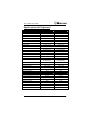
User’s Guide
Titan™ Series
120/320 Channel VHF-Low Band Mobile
120/320 Channel VHF-High Band Mobile
120/320 Channel UHF-High Band Mobile
www.midlandradio.com
Titan™ Mobile User’s Guide
FCC RF EXPOSURE COMPLIANCE REQUIREMENTS
FOR OCCUPATIONAL USE ONLY
The FCC has adopted a safety standard for human exposure to RF energy. Proper
operation of this radio under normal conditions results in user exposure to RF energy
below the Occupational Safety and Health Act and Federal Communication
Commission limits.
Mandatory Safety Instructions to Installers and Users:
This radio is NOT approved for use by the general population in an uncontrolled
environment. This radio is restricted to occupational use and work related operations
only. Radio operators must have the knowledge to control their exposure conditions
and the exposure conditions of bystanders and/or passengers to satisfy the lower
exposure limit allowed for General Population.
To comply with FCC RF exposure limits, DO NOT operate the transmitter of this mobile
radio when a person outside the vehicle is within 38 inches (94 centimeters) of the
antenna.
The antenna supplied by the manufacturer or radio dealer must be mounted at a
location such that during radio transmission, no person or persons can come closer
than the above indicated minimum safe distance to the antenna, i.e. 38 inches. To
comply with current FCC RF exposure limits, the antenna must be installed at or
exceeding the minimum safe distance stated above, and in accordance with the
requirements of the antenna manufacturer or supplier.
Vehicle Installation Instructions:
The antenna used for this transmitter must be mounted on the center of the roof ONLY
and must be installed in vehicle having the following characteristics in order to prevent
bystanders and passengers from being exposed to levels exceeding the limits for
General Population/Uncontrolled Exposure environment:
1.
All passengers must be sitting under a solid metal roof.
2.
Rooftop width must be at least 76 inches (183 centimeters) OR the edges of the
physical boundary of the vehicle must be at least 76 inches apart.
DO NOT operate the radio without the proper antenna installed. Do not substitute any
antenna for the one supplied or recommended by the manufacturer or radio dealer. The
antenna gain must not exceed 0 dBd. By not following the antenna recommendations
you may be exposing person(s) to excess radio frequency radiation. You may contact
your radio dealer or the manufacturer for further instructions.
DO NOT transmit more than 50% of total radio use time (50% duty cycle). Transmitting
for more than 50% of the time can cause FCC RF exposure compliance requirements
to be exceeded. This radio is transmitting whenever the TX icon is displayed on the
radio LCD. Pressing the PTT switch on the side of the microphone normally causes the
radio to transmit.
The preceding information is provided to make you aware of RF exposure and
how to ensure that this radio is operated within FCC RF exposure limits.
You, as the qualified end-user of this radio device must control the exposure conditions
of bystanders to ensure the minimum separation distance, stated above for satisfying
FCC RF exposure compliance, is maintained between the antenna and nearby
persons. Transmit only when all person(s) are at least the minimum distance from the
properly installed, externally mounted antenna.
2
© 2005, Midland Radio Corporation
Titan™ Mobile User’s Guide
Contents
Contents................................................................................... 3
Conventions and Symbols in this Book ................................... 4
Disclaimer ................................................................................ 4
Safety ....................................................................................... 4
Introduction .............................................................................. 6
Radio Models ....................................................................... 6
Radio Features..................................................................... 7
Recommended Accessories and Options ............................ 8
Radio Controls ......................................................................... 9
Standard LCD Details........................................................... 9
Deluxe LCD Details .............................................................. 9
Standard Control Head......................................................... 9
Standard Control Head....................................................... 10
Deluxe Control Head .......................................................... 10
Setup...................................................................................... 12
Unpacking .......................................................................... 12
Installation .......................................................................... 12
Operation ............................................................................... 13
Turning the Radio On and Off ............................................ 13
Channel Selection .............................................................. 13
Group Selection.................................................................. 13
Receiving Transmissions from Other Radios..................... 13
Transmitting to Other Radios ............................................. 15
Scanning Channels ............................................................ 16
Editing Your Scan List ........................................................ 20
DTMF ANI .......................................................................... 21
Squelch and Other Menu Functions ...................................... 21
Check Code Quick Reference ............................................... 22
Specifications (VHF low band)............................................... 23
Specifications (VHF high band) ............................................. 24
Specifications (UHF high band) ............................................. 25
Titan Mobile Connectors ........................................................ 26
Microphone Connector ....................................................... 26
Mid-Power Connector......................................................... 26
High-Power Connectors ..................................................... 26
Warranty Statement ............................................................... 27
© 2005, Midland Radio Corporation
3
Titan™ Mobile User’s Guide
Conventions and Symbols in this Book
This symbol marks a “caution”. Cautions are special notices
which you should read and follow carefully to avoid possible
damage to your equipment and to avoid potential danger to
yourself or other people.
!
This symbol marks an “important point”. Important points are
specific instructions which should be followed closely for proper
operation.
This symbol marks a “note”. Notes are hints or tips which offer
additional information to help you.
Disclaimer
Midland Radio Corporation is committed to continuous quality
improvements, for this reason specifications may change without
prior notice.
Every effort has been made to ensure that the information in this
document is complete, accurate, and up-to-date. Midland
assumes no responsibility for the results of errors beyond its
control. The manufacturer of this equipment also cannot
guarantee that changes in the equipment made by unauthorized
people will not affect the transceiver’s performance or functions.
Safety
Your Titan™ mobile transceiver has been carefully designed to
give you years of safe, reliable performance. As with all electrical
equipment, however, there are a few basic precautions you
should take to avoid injury to yourself or damage to the radio:
4
Read the instructions in this book carefully. Be sure to save it for
future reference.
Read and follow all warning and instruction labels on the radio
itself.
Be sure the PTT button is not pressed when you do not need to
transmit.
© 2005, Midland Radio Corporation
Titan™ Mobile User’s Guide
Do not operate the radio near unshielded electrical blasting caps
or in an explosive atmosphere.
Do not operate the transmitter of any radio unless all RF
connectors are secure.
All equipment must be properly grounded for safe operation.
Do not allow children to operate or play with the radio equipment.
Never attempt to disassemble or service the radio yourself. All
equipment should be serviced by a qualified technician. Contact you
local dealer or communications coordinator for assistance.
It is mandatory that radio installations in vehicles fueled by
liquefied petroleum gas conform to the NFPA 58 standard. National
Fire Protection Association Standard, NFPA 58, applies to radio
installations in vehicles fueled by liquefied petroleum (LP) gas with the
LP gas container in the trunk or other sealed-off space within the interior
of the vehicle. This standard requires that:
1.
Any space containing radio equipment shall be isolated by a seal
from the space in which the LP gas container and its fittings are
located.
2.
Remote (outside) filling connections shall be vented to the
outside.
Do not allow the antenna to touch or come in very close proximity
with the eyes, face, or any exposed body parts while the radio is
transmitting.
The above warning list is not intended to include all hazards that may
be encountered when using this radio.
© 2005, Midland Radio Corporation
5
Titan™ Mobile User’s Guide
Introduction
Congratulations! By choosing the Midland Titan™ mobile
transceiver, you have selected a professional grade radio. Its
rugged design will provide years of reliable service and
exceptional performance.
Radio Models
The models in the Titan mobile radio line allow selection by
frequency band, transmit power, control head, and mounting
configuration.
70-0511(X) - 60 W, VHF low band, standard head, dash mount, B: 36-42 MHz,
C: 42-50 MHz
70-0514(X) - 60 W, VHF low band, deluxe head, dash mount, B: 36-42 MHz, C:
42-50 MHz
70-0571(X) - 110 W, VHF low band, standard head, dash mount, A: 30-36 MHz,
B: 36-42 MHz, C: 42-50 MHz
70-0574(X) - 110 W, VHF low band, deluxe head, dash mount, A: 30-36 MHz, B:
36-42 MHz, C: 42-50 MHz
70-0611(X) - 60 W, VHF low band, standard head, trunk mount, B: 36-42 MHz,
C: 42-50 MHz
70-0614(X) - 60 W, VHF low band, deluxe head, trunk mount, B: 36-42 MHz, C:
42-50 MHz
70-0671(X) - 110 W, VHF low band, standard head, trunk mount, A: 30-36 MHz,
B: 36-42 MHz, C: 42-50 MHz
70-0674(X) - 110 W, VHF low band, deluxe head, trunk mount, A: 30-36 MHz, B:
36-42 MHz, C: 42-50 MHz
70-1341B - 50 W, VHF high band, standard head, dash mount, B: 150-174 MHz
70-1344B - 50 W, VHF high band, deluxe head, dash mount, B: 150-174 MHz
70-1391B - 110 W, VHF high band, standard head, dash mount, B: 150-174 MHz
70-1394B - 110 W, VHF high band, deluxe head, dash mount, B: 150-174 MHz
70-1441B - 50 W, VHF high band, standard head, trunk mount, B: 150-174 MHz
70-1444B - 50 W, VHF high band, deluxe head, trunk mount, B: 150-174 MHz
70-1491B - 110 W, VHF high band, standard head, trunk mount, B: 150-174 MHz
70-1494B - 110 W, VHF high band, deluxe head, trunk mount, B: 150-174 MHz
70-1541B - 40 W, UHF high band, standard head, dash mount, B: 450-470 MHz
70-1544B - 40 W, UHF high band, deluxe head, dash mount, B: 450-470 MHz
70-1591B - 100 W, UHF high band, standard head, dash mount, B: 450-470 MHz
70-1594B - 100 W, UHF high band, deluxe head, dash mount, B: 450-470 MHz
70-1641B - 40 W, UHF high band, standard head, trunk mount, B: 450-470 MHz
70-1644B - 40 W, UHF high band, deluxe head, trunk mount, B: 450-470 MHz
70-1691B - 100 W, UHF high band, standard head, trunk mount, 450-470 MHz
70-1694B - 100 W, UHF high band, deluxe head, trunk mount, 450-470 MHz
6
© 2005, Midland Radio Corporation
Titan™ Mobile User’s Guide
Radio Features
The Titan series mobile transceiver is a programmable,
synthesized radio featuring:
5 40 Watts (UHF)/50 Watts (VHF-High Band)/60 Watts (VHF-Low Band)
transmit power for mid power radios. 100 Watts (UHF)/110 Watts (VHFHigh Band)/110 Watts (VHF-Low Band) transmit power for high power
radios
5 12.5 KHz and 25 KHz channel spacing programmable per channel.
5 Auxiliary button for activation of optional accessories.
5 Software adjusted noise squelch level. The squelch level may be easily
adjusted using the menu functions.
5 Flexible scan programming allows for two priority channels to be
assigned. Priority scan, priority transmit and priority lookback are
standard. Nuisance delete and scan escape functions are available.
5 Extensive and simple scan list editing functions.
5 User selectable scan modes (busy scan, priority scan and public safety
scan).
5 47 CTCSS tones and 104 DCS codes are programmable per channel.
5 A busy channel lockout feature is programmable. An override function is
available to allow transmission during repeater hangtime.
5 A transmit time-out timer may be programmed to limit continuous
transmission time.
5 The AUX button may be configured to provide repeater talk-around
without using an additional channel.
5 2-tone decode built-in. Individual and group calls can be decoded.
5 A DTMF ANI sequence may be sent on PTT press. A thirty second PTT
release timer is standard.
5 Audio compandering programmable per channel.
5 Radio alignment is performed using programming software.
© 2005, Midland Radio Corporation
7
Titan™ Mobile User’s Guide
Recommended Accessories and Options
Microphones
70-2184
70-2185
70-2188
70-2328A
DTMF display and programming microphone
DTMF microphone
Weatherproof microphone
Replacement microphone
Control Heads, Mounting Brackets and Speakers
70-2202
Standard (three character) control head
70-2203
Deluxe (twelve character) control head
70-2278
Trunk mount conversion kit
70-2290
Under dash mounting bracket
70-2291
Trunk mount tray
70-2358
Remote speaker
Cables
70-0038
70-0039
70-0042
70-0046
70-0076
70-0076QC
6 meter DC power cable (mid power radios)
2 meter DC power cable (mid power radios)
2 meter DC power cable (high power radios)
6 meter DC power cable (high power radios)
6 meter control cable
7 meter quick connect control cable
Base Equipment
70-2020D
70-2286
70-2305BT
Tone termination panel (factory install only)
11 Amp power supply w/shroud (mid-power radios)
Desktop microphone
Options
70-2182
70-2197
70-2271(A)
70-2945-1A
70-2945-2A
8
320 channel expansion kit
Noise filter
Ignition sense kit (factory install only)
Internal VHF mobile repeater package
for VHF-low and UHF band mobiles
(factory install only)
Internal UHF mobile repeater package
for VHF-low and VHF-high band mobiles
(factory install only)
© 2005, Midland Radio Corporation
Titan™ Mobile User’s Guide
Radio Controls
Standard LCD Details
Transmit
Icon
Busy Channel
Icon
Monitor
Icon
Busy Scan
Icon
Priority Scan
Icon
3 Character AlphaNumeric Channel Label
Auxiliary Mode
Icon
Add/Delete Mode
Icon
Deluxe LCD Details
Transmit
Icon
Busy Channel
Icon
Busy Scan
Icon
Monitor
Icon
© 2005, Midland Radio Corporation
Priority Scan
Icon
Auxiliary Mode
Icon
Add/Delete
Mode Icon
12 Character AlphaNumeric Channel Label
9
Titan™ Mobile User’s Guide
Standard Control Head
1
2
6
3
4
5
7
8
9
Deluxe Control Head
1
6
10
2
3
7
4
5
8
© 2005, Midland Radio Corporation
Titan™ Mobile User’s Guide
MON
SCAN
1.
MON button - Press and release the MON button to defeat
any programmed CTCSS/DCS and check the radio channel
for traffic before transmitting. Press and release the MON
button again to return to CTCSS/DCS mode.
2.
SCAN button - Press and release the SCAN button to
activate scan mode. Depending on the scan mode, the PRI
icon (priority scan modes) or SCAN icon (busy scan modes)
will be displayed while scan mode is activated. Press and
release the SCAN button again to turn scan off. Refer to the
detailed scan description for further information.
Press and hold the SCAN button for two seconds to make
the selected channel a second priority channel.
3.
LCD display - Provides channel and operating information.
AUX
4.
AUX button - Press and release the AUX button to activate
auxiliary functions or options. Scan escape is the default
function. The AUX icon (AX1 icon on standard head) will be
displayed while the auxiliary function or option is active.
A/D
5.
A/D button - Press and release the A/D button to enter scan
list add/delete mode. The A/D icon (AX2 icon on standard
head) will be displayed while scan list add/delete mode is
active. Press and release the A/D button again to exit scan
list add/delete mode. See the scan list editing description for
more information.
6.
Microphone jack – 8 pin modular plug for microphone
connection.
7.
Power/Volume knob - Press and hold for two seconds to
turn the radio on. Press and hold again to turn the radio off.
Rotate clockwise to increase volume.
8.
Channel/Menu knob - Rotate to scroll through the available
channels. Depending on programming, the channel scroll
may stop or rollover when the lowest or highest channel is
reached.
Press the knob once to select the first menu function
(squelch). Press again to step to the next menu function.
Refer to the menu function description for further
information.
9.
Internal speaker - Standard control head only, external
speaker required for deluxe head.
© 2005, Midland Radio Corporation
11
Titan™ Mobile User’s Guide
Setup
Unpacking
The following items are supplied in the standard package:
5 One transceiver chassis
5 One control head.
5 One microphone.
5 One DC power cord.
5 One mounting bracket or tray.
5 One mounting hardware package.
5 One user’s manual.
Additional model dependent equipment:
5 One trunk mount kit
5 One remote speaker (standard with deluxe control head)
Installation
Radio installation should only be done by qualified and trained
personnel, familiar with automotive electronics installation, and
FCC RF exposure guidelines. This transceiver should be
installed in 12V negative ground vehicles only. Complete
installation instructions are available in the corresponding radio
service manual.
Antenna selection, installation and positioning requires
knowledge of RF radiation and exposure conditions and should
be performed by qualified personnel only. Please consult your
dealer or communications coordinator for more information.
12
© 2005, Midland Radio Corporation
Titan™ Mobile User’s Guide
Operation
Turning the Radio On and Off
Press and hold the power/volume knob for two seconds to turn
the radio on. The radio will perform a power-on test, which
includes lighting all display segments and may sound a single
beep when complete. Under certain circumstances, such as after
the radio has been reprogrammed, it may also display a check
code and sound a triple beep. Rotate the volume knob clockwise
to increase the volume.
Channel Selection
Rotate the channel/menu knob to select the channel. The radio
may be programmed to stop or Rollover when it reaches the
highest and lowest channels. Please consult your dealer or
communications coordinator regarding channels programmed in
your radio.
Group Selection
Your radio channels may be organized into channel groupings
that further sort and organize your channels. To select a different
group of channels, press the channel/menu knob twice, or until
the GRP is displayed, then rotate to the channel/menu knob until
the desired new group number or name is displayed. To exit,
press the channel/menu knob repeatedly until the first channel in
the new group is displayed.
Please consult your dealer or communications coordinator
regarding channel groups programmed in your radio.
Receiving Transmissions from Other Radios
Each channel of your radio may be programmed for carrier
squelch operation, CTCSS/DCS operation or 2-tone operation.
The following paragraphs describe these modes of operation.
Ask your dealer or communications coordinator if you have
questions on how your radio has been programmed to operate.
© 2005, Midland Radio Corporation
13
Titan™ Mobile User’s Guide
Carrier Squelch Operation
A signal that matches the programmed receive frequency will be
heard if it is of sufficient strength to exceed the squelch
threshold. An on frequency signal exceeding the squelch
threshold level will be indicated by the BUSY icon.
CTCSS/DCS Operation
CTCSS or DCS signaling adds an additional condition to carrier
squelch operation. In addition to the signal having to exceed the
squelch threshold level, the received signal must also have the
correct CTCSS or DCS tone or code before the audio will be
passed to the speaker. CTCSS or DCS signaling allows multiple
users on the same frequency to hear only signals which have
their correct CTCSS tone or DCS code. An on frequency signal
without the correct CTCSS or DCS signal will be indicated by the
BUSY icon while no audio is heard.
CTCSS/DCS allows multiple users to share the same frequency.
However CTCSS/DCS is only useful to avoid disturbing other users with
messages not related to them. If more than one radio is transmitting at
the same time, this will cause interference. Do not transmit if the BUSY
icon is on. Wait until the channel is clear before transmitting.
2-tone Operation
2-tone signaling allows individual or group calls to be made to
your radio. On channels programmed for 2-tone decode
operation, you can press the channel/menu knob for two
seconds to mute all receive signals until the programmed 2-tone
signal has been decoded. After the programmed 2-tone signal is
decoded, the radio will beep, and subsequent receive audio will
be heard over the speaker. Press and hold the channel/menu
knob again to mute the radio until it receives a new call. Pressing
the MON button or PTT will disable the 2-tone muting function.
14
Consult your dealer or communications coordinator for further details on
how your radio has been programmed for 2-tone operation.
© 2005, Midland Radio Corporation
Titan™ Mobile User’s Guide
2-tone signaling allows users to receive only calls intended for them.
However, more than one radio transmitting at a time will still cause
interference. Do not transmit if the BUSY icon is on. Wait until the
channel is clear before transmitting.
Transmitting to Other Radios
Before transmitting, the FCC requires you monitor the channel to
make sure it is clear. Transmitting while someone else is
transmitting will create interference and disrupt both
conversations.
Follow these steps to transmit to other radios.
1.
Monitor the channel by pressing the MON button. Channel activity is also
indicated by the BUSY icon.
2.
If the channel is clear, press and hold the push to talk (PTT) switch on the
side of the microphone.
3.
The TX icon will display while the radio is transmitting.
4.
Hold the microphone approximately 2 inches from your mouth and speak
across the face of the microphone in a clear, normal voice.
5.
Keep the PTT switch pressed until you have finished speaking.
6.
Release the PTT switch to return to receive mode.
Do not shout! It will only create distortion.
Press PTT before you start talking and release PTT after you have
finished speaking.
Your radio doesn’t allow you to talk and receive simultaneously, so keep
your transmission short. When you are transmitting, other people can
not. Use common sense and do not occupy the channel too much.
The radio might be programmed with a timeout timer which will
automatically end your transmission after a preset time. In this case
release PTT and wait for a few seconds. The radio transmitter will be
enabled again after a few seconds. Ask your dealer or communications
coordinator for further details.
The radio might be programmed for busy channel lock out, which
automatically disables the transmitter if your channel is busy. In this
case wait until the channel is clear.
© 2005, Midland Radio Corporation
15
Titan™ Mobile User’s Guide
Scanning Channels
If you have more than one channel programmed, your Titan
radio may be programmed to allow you to scan them. Press and
release the SCAN button to activate scan. The radio will begin
checking all channels in the scan list for activity. The SCAN icon
or PRI icon will be displayed while the radio is scanning. To turn
scan off, press and release the SCAN button again.
The scan mode and scan list are initially programmed by your
dealer or communications coordinator. If a priority scan mode
has been selected, the priority channel is checked for activity
more often than other channels in the scan list. The priority
channel will also be checked for activity while the radio is
receiving on a non-priority channel.
Once the receive signal ends, the radio may be programmed to
wait a period of time before resuming scan. When the Scan hold
after RX timer has expired, scanning will resume. There is also a
Scan hold after TX timer that will be started whenever the radio
has ceased transmitting on a channel. Your dealer or
communications coordinator will customize the scan options for
your particular situation; the following paragraphs detail the
available options. The scan mode depends on both the dealer
programmed Scan Selection and the user selection from the
menu functions as outlined in the table.
Dealer programmed Scan Selection
User menu
selection
Normal
Modify
Second
PS
PRI
Priority scan
Priority scan
Priority
Monitor
Public Safety
scan
SCN
Busy scan
Alternate
Busy scan
Alternate
Busy scan
N/A
P/S
N/A
No scan
Priority scan
N/A
16
© 2005, Midland Radio Corporation
Titan™ Mobile User’s Guide
Priority Scan
Priority scan is available when your dealer has programmed
Normal or Modify Scan Selection. Use the menu function to
select PRI scan mode.
The default user selection is PRI scan mode.
If enabled in programming, you may assign a second priority
channel before starting scan. Select the desired second priority
channel using the channel selector, then press and hold the
SCAN button for two seconds. The channel display will flash
when a second priority channel is displayed.
Press and release SCAN to activate Priority scan. The channel
selected when scan is started will be assigned as the first priority
channel. The priority channel(s) will be checked more often than
the other channels in the scan list. While scanning in Priority
scan mode, the radio will display “---“ and the PRI icon. If activity
is detected on a channel, the radio will pause scan and display
that channel. While stopped on a non-priority channel, the radio
will continue to check for activity on the priority channel(s). This
is called priority channel lookback, and the receive audio from
the non-priority channel will be briefly interrupted while priority
lookback occurs. While the radio is stopped on a non-priority
channel it may be deleted from the scan list by briefly pressing
the A/D button. This is the nuisance channel delete function. The
priority channel(s) can not be deleted from the scan list. To
resume scanning at the next channel in the scan list, without
deleting the channel, rotate the channel/menu knob clockwise.
In Priority scan mode the scan escape function may have been
enabled by your dealer or communications coordinator. To
temporarily suspend scan and switch to the last received
channel, press and release the AUX button. When finished
operating on the last received channel, press and release the
AUX button again to resume scan operation. The priority channel
selections will not be changed by the scan escape function.
© 2005, Midland Radio Corporation
17
Titan™ Mobile User’s Guide
Busy Scan
Busy scan is available when your dealer has programmed
Normal or Modify Scan Selection. Use the menu function to
select SCN scan mode.
The default user selection is PRI scan mode.
Press and release SCAN to activate Busy scan. All channels in
your scan list will be checked for activity, with no preference
given to any channel. While scanning in busy scan mode, the
radio will display “---“ and the SCAN icon. If activity is detected
on a channel, the radio will pause scan and display that channel.
While the radio is paused on a channel it may be deleted from
the scan list by briefly pressing the A/D button. This is the
nuisance channel delete function. To resume scanning at the
next channel in the scan list, without deleting the channel, rotate
the channel/menu knob clockwise.
Public Safety Scan
Public Safety scan is available when your dealer has
programmed PS Scan Selection.
No user scan mode selection is possible in Public Safety scan mode.
The user selection is fixed at PRI scan mode.
If enabled in programming, you may assign a second priority
channel before starting scan. Select the desired second priority
channel using the channel selector, then press and hold the
SCAN button for two seconds. The channel display will flash
when a second priority channel is displayed.
Press and release SCAN to activate Public Safety scan. The
channel selected when scan is started will be assigned as the
first priority channel. The priority channel(s) will be checked more
often than the other channels in the scan list. While scanning in
Public Safety scan mode, the radio will display the first priority
channel and a flashing PRI icon. While the radio is scanning, the
channel knob may be rotated to select and display a new first
18
© 2005, Midland Radio Corporation
Titan™ Mobile User’s Guide
priority channel. This is the primary difference between Public
Safety scan and Priority scan.
If activity is detected on a channel, the radio will pause scan and
display that channel. While stopped on a non-priority channel,
the radio will continue to check for activity on the priority
channel(s). This is called priority channel lookback, and the
receive audio from the non-priority channel will be briefly
interrupted while priority lookback occurs. While the radio is
stopped on a non-priority channel it may be deleted from the
scan list by briefly pressing the A/D button. This is the nuisance
channel delete function. The priority channel(s) can not be
deleted from the scan list. To resume scanning at the next
channel in the scan list, without deleting the channel, rotate the
channel/menu knob clockwise.
Priority Monitor Mode (Dual watch)
Priority Monitor mode is available when your dealer has
programmed Second Scan Selection. Use the menu function to
select PRI scan mode.
The default user selection is PRI scan mode. User selections of SCN
(Busy scan) and P/S (Priority scan) are also possible when your dealer
has programmed Second Scan Selection.
If enabled in programming, you may assign a second priority
channel before initiating priority monitoring. Select the desired
second priority channel using the channel selector, then press
and hold the SCAN button for two seconds. The channel display
will flash when a second priority channel is displayed.
Press and release SCAN to activate Priority Monitor mode. The
channel selected when priority monitoring is started will be
assigned as the first priority channel. Then use the
channel/menu knob to select a channel of operation, while
continuing to monitor the priority channel(s) for activity. While in
Priority Monitor mode, the radio will normally display the
operating channel and the PRI icon.
© 2005, Midland Radio Corporation
19
Titan™ Mobile User’s Guide
If activity is detected on a priority channel the radio will switch to
and display the priority channel.
Transmitting While in Scan Mode
In Busy scan mode, when PTT is pressed while scanning, the
radio will transmit on the last received channel. If no last receive
channel has been established since scan was started, transmit
will occur on the scan start channel.
In Priority scan or Public Safety scan mode, the radio will always
transmit on the first priority channel while scan is turned on. The
first priority channel will also always be displayed while
transmitting.
If Priority Monitor mode has been activated, the radio will always
transmit on the displayed channel (whether operating channel or
priority channel(s)).
Editing Your Scan List
One of the features of your Titan mobile radio is the ability to add
channels and groups of channels to your scan list. Of course,
you may also delete channels from your scan list. These
changes are saved in radio EEPROM and are not temporary.
Depending on dealer programming the scan list edits may be
retained indefinitely or may be reset when scan or the radio are
turned off. Or, you may reset the scan list back to dealer
programming at any time by pressing the A/D button until the
second beep is heard.
The channels in your radio may be organized into groups and a
menu function allows you to select whether the scan will check
only channels in the current group or in all groups. Then within
each group, each individual channel may be selected for scan.
As you are editing the scan list, if the PRI icon or SCAN icon is
on, the channel is currently in the scan list. If the neither icon is
on that channel will not be scanned.
20
© 2005, Midland Radio Corporation
Titan™ Mobile User’s Guide
Press and release the A/D button to enter scan add/delete mode.
The A/D icon (AX2 on standard head) will be displayed while
scan add/delete mode is active. Once you are in add/delete
mode, use the channel knob to scroll through the channels. To
add a channel to the scan list, or remove a channel that is
already in the list, press and release the scan button. The PRI or
SCAN icon will toggle on/off indicating scan list status. Press and
release the A/D button again to exit add/delete mode.
DTMF ANI
The Titan mobile radio may be programmed to automatically
send a DTMF ANI signal when you press PTT on certain
channels. Or, if ANI has been configured by programming, but
not enabled for the channel, you can use the menu function to
temporarily enable ANI.
A thirty second release timer will be started each time you release PTT.
The ANI will not be sent unless this timer has expired.
Squelch and Other Menu Functions
Several parameters may be changed using the menu functions.
Menu selections (press menu)
Squelch
Group
Group scan
S(QL) 0-80
GRP (name)
OGS, AGS
User scan
PRI, SCN, P/S
Backlight
BL (O)N, (OF)F
ANI
AN(I) (O)N, (OF)F
1.
Press the channel/menu knob to select the first menu item, squelch level,
SQL.
2.
Rotate the channel/menu knob to change the squelch level. The squelch
adjustment range is 0 – 80, where 80 is the least sensitive or tight squelch
position. Adjust squelch at least five steps above threshold (after BUSY icon
extinguishes) for best operation.
© 2005, Midland Radio Corporation
21
Titan™ Mobile User’s Guide
3.
Press the channel menu knob again to save the new squelch setting and
proceed to next menu item, group selection, GRP.
!
The squelch setting is written to EEPROM by pressing the
channel/menu knob. If the menu function is left to timeout, the new
squelch setting will not be saved, and the radio will revert to the
previous settings at power-on.
4.
Rotate the channel/menu knob to select a new channel group.
5.
Press the channel/menu knob to proceed to the next menu item, group scan
selection.
This item only appears on the menu if more than one channel group has
been programmed.
6.
Rotate the channel/menu knob to select one group scan, OGS or all group
scan, AGS.
7.
Press the channel/menu knob to proceed to the next menu item, scan
selection.
8.
Rotate the channel/menu knob to select PRI, SCN or P/S. Follow the same
steps to set the additional menu items, backlight and ANI on/off.
Please see the appropriate sections for further details, not all selections
may be available.
Check Code Quick Reference
Display
Description
Action
E(rr)1
MCU RAM/ROM error
E(rr)2
E(rr)3
No model or channel data
Synthesizer unlock
E(rr)4
E(rr)6
E(rr)7
Channel data checksum
RAM/ROM data conflict
EEPROM backup data reset
Re-program with corrected data
Call for service (radio operational)
Turn radio off by front panel to write
new backup data
E(rr)8
E(rr)9
Serial communication error
Cloning error
Check connections and retry
Check instructions and retry.
22
Service required (radio not
operational)
Re-program with corrected data
Check frequency programming or
call for service
© 2005, Midland Radio Corporation
Titan™ Mobile User’s Guide
Specifications (VHF low band)
General specifications
Mid-Power
High-Power
Frequency range
A: 30-36 MHz, B: 36-42 MHz, C: 42-50 MHz
FCC ID numbers
NCP700511B
NCP700511C
FCC type acceptance
Maximum number of channels
Maximum number of groups
Channel spacing
Channel stepping
CTCSS/DCS per channel
Input voltage
MIL spec
MMA700671A
NCP700671B
NCP700671C
Part 90
Part 90
120 or 320 opt.
120 or 320 opt.
40
40
20 KHz
20 KHz
2.5/5.0/6.25 KHz
2.5/5.0/6.25 KHz
47 CTCSS/104 DCS
47 CTCSS/104 DCS
13.6 Vdc ±15%
13.6 Vdc ±15%
810E Rain, Salt, Fog & Vibration
Size (HxWxD)
Weight
2.75x7.25x8.75 in
2.75x7.25x14.0 in
(70x184x222 mm)
(70x184x356 mm)
6.0 lbs (2.7 kg)
10.2 lbs (4.6 kg)
±2.5 ppm
±2.5 ppm
EIA/TIA-603 receiver specs
Frequency stability (-30° to +60° C)
12 dB SINAD sensitivity
0.25 µV
0.25 µV
90 dB (±20 KHz)
90 dB (±20 KHz)
80 dB (±50/±100 KHz)
80 dB (±50/±100 KHz)
Selectivity
Intermodulation rejection
Spurious rejection
Acceptable radio freq displacement
Squelch sensitivity
80 dB
80 dB
±2 KHz WB
±2 KHz WB
0.18 µV max
0.18 µV max
per EIA/TIA-603 specs
per EIA/TIA-603 specs
5W int./10W ext.
5W int./10W ext.
50 Ω
50 Ω
RF power output
60 Watts
110 Watts
Frequency stability (-30° to +60° C)
±2.5 ppm
±2.5 ppm
Modulation type
16KOF3E
16KOF3E
Audio response
Audio output <5% THD into 8Ω
RF input impedance
EIA/TIA-603 transmitter specs
Adjacent channel emissions
70 dB
70 dB
Spurious emissions
80 dB
80 dB
FM hum & noise
50 dB
50 dB
Audio response
per EIA/TIA-603 specs
per EIA/TIA-603 specs
Audio distortion (1KHz @ 60%dev.)
<2%
<2%
RF output impedance
50 Ω
50 Ω
© 2005, Midland Radio Corporation
23
Titan™ Mobile User’s Guide
Specifications (VHF high band)
General specifications
Mid-Power
High-Power
Frequency range
B: 150-174 MHz
B: 150-174 MHz
FCC ID numbers
NCP701341B
NCP701491B
FCC type acceptance
Maximum number of channels
Maximum number of groups
Channel spacing
Channel stepping
CTCSS/DCS per channel
Input voltage
MIL spec
Size (HxWxD)
Weight
Part 90
Part 90
120 or 320 opt.
120 or 320 opt.
40
40
12.5/25/30 KHz
12.5/25/30 KHz
2.5/5.0/6.25 KHz
2.5/5.0/6.25 KHz
47 CTCSS/104 DCS
47 CTCSS/104 DCS
13.6 Vdc ±15%
13.6 Vdc ±15%
810E Rain, Salt, Fog & Vibration
2.75x7.25x8.75 in
2.75x7.25x14.0 in
(70x184x222 mm)
(70x184x356 mm)
6.0 lbs (2.7 kg)
10.2 lbs (4.6 kg)
±2.5 ppm
±2.5 ppm
EIA/TIA-603 receiver specs
Frequency stability (-30° to +60° C)
12 dB SINAD sensitivity
Selectivity
Intermodulation rejection
Spurious rejection
Acceptable radio freq displacement
Squelch sensitivity
0.25 µV
0.25 µV
85 dB (±25/±30 KHz)
85 dB (±25/±30 KHz)
75 dB (±12.5 KHz)
80 dB (±25 KHz)
75 dB (±12.5 KHz)
80 dB (±25 KHz)
80 dB
80 dB
±1 KHz NB/±2 KHz WB
±1 KHz NB/±2 KHz WB
0.18 µV max
0.18 µV max
per EIA/TIA-603 specs
per EIA/TIA-603 specs
5W int./10W ext.
5W int./10W ext.
50 Ω
50 Ω
RF power output
50 Watts
110 Watts
Frequency stability (-30° to +60° C)
±2.5 ppm
±2.5 ppm
16KOF3E/11KOF3E
16KOF3E/11KOF3E
Audio response
Audio output <5% THD into 8Ω
RF input impedance
EIA/TIA-603 transmitter specs
Modulation type
Adjacent channel emissions
80 dB
80 dB
Spurious emissions
80 dB
80 dB
FM hum & noise
50 dB
50 dB
Audio response
per EIA/TIA-603 specs
per EIA/TIA-603 specs
Audio distortion (1KHz @ 60%dev.)
<2%
<2%
RF output impedance
50 Ω
50 Ω
24
© 2005, Midland Radio Corporation
Titan™ Mobile User’s Guide
Specifications (UHF high band)
General specifications
Mid-Power
High-Power
Frequency range
B: 450-470 MHz
B: 450-470 MHz
FCC ID numbers
NCP701541B
NCP701691B
FCC type acceptance
Maximum number of channels
Maximum number of groups
Channel spacing
Channel stepping
CTCSS/DCS per channel
Input voltage
MIL spec
Part 90
Part 90
120 or 320 opt.
120 or 320 opt.
40
40
12.5/25 KHz
12.5/25 KHz
5.0/6.25 KHz
5.0/6.25 KHz
47 CTCSS/104 DCS
47 CTCSS/104 DCS
13.6 Vdc ±15%
13.6 Vdc ±15%
810E Rain, Salt, Fog & Vibration
Size (HxWxD)
Weight
2.75x7.25x8.75 in
2.75x7.25x14.0 in
(70x184x222 mm)
(70x184x356 mm)
6.0 lbs (2.7 kg)
10.2 lbs (4.6 kg)
±2.5 ppm
±2.5 ppm
EIA/TIA-603 receiver specs
Frequency stability (-30° to +60° C)
12 dB SINAD sensitivity
Selectivity
Intermodulation rejection
Spurious rejection
Acceptable radio freq displacement
0.25 µV
0.25 µV
75 dB (±25 KHz)
75 dB (±25 KHz)
75 dB (±12.5 KHz)
80 dB (±25 KHz)
75 dB (±12.5 KHz)
80 dB (±25 KHz)
80 dB
80 dB
±1 KHz NB/±2 KHz WB
±1 KHz NB/±2 KHz WB
Squelch sensitivity
0.18 µV max
0.18 µV max
per EIA/TIA-603 specs
per EIA/TIA-603 specs
5W int./10W ext.
5W int./10W ext.
50 Ω
50 Ω
RF power output
40 Watts
100 Watts
Frequency stability (-30° to +60° C)
±2.5 ppm
±2.5 ppm
16KOF3E/11KOF3E
16KOF3E/11KOF3E
Audio response
Audio output <5% THD into 8Ω
RF input impedance
EIA/TIA-603 transmitter specs
Modulation type
Adjacent channel emissions
80 dB
80 dB
Spurious emissions
80 dB
80 dB
FM hum & noise
50 dB
50 dB
Audio response
per EIA/TIA-603 specs
per EIA/TIA-603 specs
Audio distortion (1KHz @ 60%dev.)
<2%
<2%
RF output impedance
50 Ω
50 Ω
© 2005, Midland Radio Corporation
25
Titan™ Mobile User’s Guide
Titan Mobile Connectors
Microphone Connector
1.
2.
3.
4.
8
1
5.
6.
7.
8.
Mic audio
PTT
Mic ground
Hang-up (JP2) or +12V (JP1)
Remove accessory hang-up
loop to use mic hang-up.
Remove JP2 and install JP1
for DTMF microphones.
RD
SD
RTS
CTS
Mid-Power Connector
11
22
33
44
55
66
77
88
99
10
10
1.
2.
3.
Aux 1
Ground
Hang-up
Normally grounded.
4. Speaker 2
5. Internal Speaker
6. Speaker 1
Looped to pin 5 for internal
speaker.
7. Ground
8. Aux 2
9. +13.6 Vdc
10. +13.6 Vdc
High-Power Connectors
26
3
6
9
12
2
5
8
11
1
4
7
10
1.
2.
3.
Aux 1
Hang-up ground
Hang-up
Normally looped to pin 2.
4. Speaker 2
5. Internal Speaker
6. Speaker 1
Looped to pin 5 for internal
speaker.
7. NC
8. Aux 2
9-12. NC
© 2005, Midland Radio Corporation
Titan™ Mobile User’s Guide
Warranty Statement
Midland Radio Corporation (herein, Midland) warrants each new radio product manufactured
or supplied by it to be free from defects in material and workmanship under normal use and
service for a period listed below, provided that the user has complied with the requirements
stated herein.
The Warranty period begins on the date of purchase from an Authorized Midland Sales and
Service Outlet. This Warranty is offered to the original end user and is not assignable or
transferable. Midland is not responsible for any ancillary equipment attached to or used in
conjunction with Midland products.
Midland offers to the original end user a Two (2) Year Limited Warranty on Midland Business
and Industrial radio products. Accessories carry a One (1) Year Limited Warranty.
During this period, if the product fails to function under normal use because of manufacturing
defect(s) or workmanship, it should be returned to the Authorized Midland Sales and Service
Outlet from which it was purchased. The Sales and Service Outlet will repair the product or
return the product for repair to Midland or its Authorized Repair Depot. The user is
responsible for the payment of any charges or expenses incurred for the removal of the
defective product from the vehicle or other site of its use; for the transportation of the product
to the Sales and Service Outlet; for the return of the repaired / replacement product to the
site of its use and for the reinstallation of the product.
Midland shall have no obligation to make repairs or to cause replacement required, which
results from normal wear and tear or is necessitated in whole or in part by catastrophe, fault
or negligence of the user, improper or unauthorized alterations or repairs to the Product,
incorrect wiring, use of the Product in a manner for which it was not designed or by causes
external to the Product. This Warranty is void if the product serial number is altered, defaced
or removed.
Midland’s sole obligation hereunder shall be to replace or repair the Product covered in this
Warranty. Replacement, at Midland’s option, may include a similar or higher-featured
product. Repair may include the replacement of parts or boards with functionally equivalent
reconditioned or new parts or boards. Replaced parts, accessories, batteries or boards are
warranted for the balance of the original time period. All replaced parts, accessories,
batteries or boards become the property of Midland.
THE EXPRESS WARRANTIES CONTAINED HEREIN ARE IN LIEU OF ALL OTHER
WARRANTIES, EITHER EXPRESSED OR IMPLIED OR STATUTORY, INCLUDING,
WITHOUT LIMITATION, ANY WARRANTY OF MERCHANTABILITY OR FITNESS FOR A
PARTICULAR PURPOSE.
FOR ANY PRODUCT WHICH DOES NOT COMPLY WITH THE WARRANTY SPECIFIED,
THE SOLE REMEDY WILL BE REPAIR OR REPLACEMENT. IN NO EVENT WILL
MIDLAND BE LIABLE TO THE BUYER OR ITS CUSTOMERS FOR ANY DAMAGES,
INCLUDING ANY SPECIAL, INCIDENTAL, INDIRECT OR CONSEQUENTIAL DAMAGES,
OR FOR THE LOSS OF PROFIT, REVENUE OR DATA ARISING OUT OF THE USE OF
OR THE INABILITY TO USE THE PRODUCT.
This warranty is void for sales and deliveries outside of the U. S. A. and Canada.
© 2005, Midland Radio Corporation
27
This device complies with Part 15 of the FCC Rules. Operation is
subject to the condition that this device does not cause harmful
interference.
This radio operates in FCC regulated frequency bands. All radios
must be licensed by the FCC before use. Because this radio
contains a transmitter, Federal law prohibits unauthorized use or
adjustments of this radio.
5900 PARRETTA DRIVE, KANSAS CITY, MISSOURI, 64120
PHONE: (816) 241-8500, FAX: (816) 241-5713
www.midlandradio.com
Revised July 2005
Printed in Japan